Embed Size (px)
Citation preview
1
Profibus DP/V0 Description of Functions
UMG604 / UMG605 / UMG508 / UMG511 Example with a Siemens PLC
S7-300
Version 1.2
Document no: XXXXX
Janitza electronics GmbH Vor dem Polstück 1
D-35633 Lahnau Support Tel. (0 64 41) 9642-22
Fax (0 64 41) 9642-30 E-mail: [email protected]
2
General ............................................................................................................................. 3
Plug Assignment ............................................................................................................... 3
Connecting the Bus Cables ................................................................................................ 3
Profibus Profile (General) .................................................................................................. 4
Standard Profiles .............................................................................................................. 5
Creating a Profile .............................................................................................................. 6
GSD File ............................................................................................................................ 9
Incorporating the Slave Unit in the Master Software (SIMATIC S7-300) .............................. 9
Simatic variables table .................................................................................................... 11
Profibus Profiles in Graphic Programming ....................................................................... 13
Profibus Puffer ................................................................................................................ 17
Modbus Profibus Gateway .............................................................................................. 18
cover:
Version 1.0 translation English Version 1.1 Standard Profiles (S.5) Version 1.2 Profibus buffer (S.17)

3
General
The UMG604 / UMG605 / UMG508 / UMG511 offer a variety of communication options. The following protocols are offered on the interfaces: Modbus RTU, Modbus TCP/IP, Modbus over TCP/IP (Modbus Gateway), BacNet or Profibus DP V0. This description of functions is a supplement to the handbook and describes the necessary setup stages of the respective function step-by-step. More functional descriptions can be found on www.janitza.de. All measurement values that the Power Analyzer provides can be incorporated in a profibus profile. Additionally, it is possible to create personally defined variables through graphic programming; the user-defined variables can be allocated to a profibus profile. The Power Analyzer provides 255 profiles, whereby the first 16 profiles are prepared for the fixed configuration. Profiles 16 to 255 can be created and occupied in the graphic programming. There is read and write access to the profile which makes it possible to describe digital outputs or user-defined variables from the PLC. The description of functions has been created with GridVis 1.6.0 and with UMG604 Firmware 1.095 (available from November 2009).
Plug Assignment
The Power Analyzer supports Profibus DP V0 to 12Mbaud. The profibus connection of the Power Analyzer is designed as a 9-pole sub D socket. We recommend a 9-pole profibus plug (type: SUBCON-PLUS-ProfiB/AX/SC manufacturer: Phoenix art. no.: 2744380 or equivalent) for connection.
Power Analyzer (P/EP version)
Profibus plug SUBCON
Connecting the Bus Cables
Always connect the incoming bus cable to the 1A/1B connections (including at the start of the bus system!) The continuing bus cable is always connected to the 2A/2B connections. The terminator resistors are activated at the start and end of the bus system using the slide switches. The connection clamps (2A/2B) are simultaneously switched off for the continuing bus cable.
Illustration 1
VP (6)
GND (5)
3
8
2B
2A
1B
1A
ON / OFF
4
Profibus Profile (General)
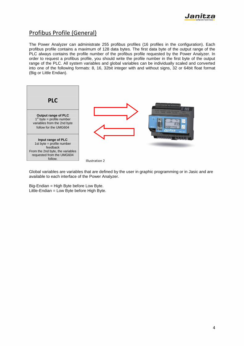
The Power Analyzer can administrate 255 profibus profiles (16 profiles in the configuration). Each profibus profile contains a maximum of 128 data bytes. The first data byte of the output range of the PLC always contains the profile number of the profibus profile requested by the Power Analyzer. In order to request a profibus profile, you should write the profile number in the first byte of the output range of the PLC. All system variables and global variables can be individually scaled and converted into one of the following formats: 8, 16, 32bit integer with and without signs, 32 or 64bit float format (Big or Little Endian).
Global variables are variables that are defined by the user in graphic programming or in Jasic and are available to each interface of the Power Analyzer. Big-Endian = High Byte before Low Byte. Little-Endian = Low Byte before High Byte.
PLC
Output range of PLC
1st byte = profile number
variables from the 2nd byte
follow for the UMG604
Input range of PLC
1st byte = profile number feedback
From the 2nd byte, the variables requested from the UMG604
follow. Illustration 2
5
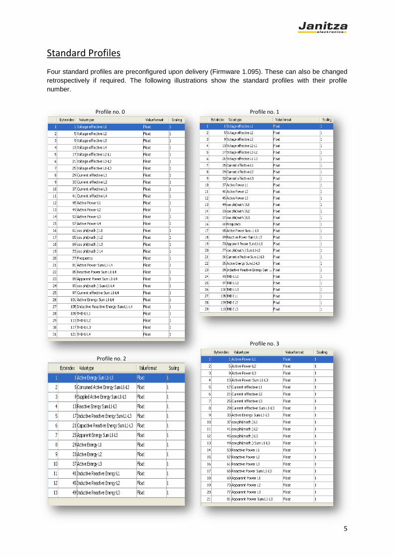
Standard Profiles
Four standard profiles are preconfigured upon delivery (Firmware 1.095). These can also be changed
retrospectively if required. The following illustrations show the standard profiles with their profile
number.
Profile no. 2
Profile no. 0 Profile no. 1
Profile no. 3

6
Creating a Profile
The profiles are created in the unit configuration field. You have access to the profibus profile using
the “configure unit” button in the unit list.
In the “field bus profile” tab, selected measurement values can now be allocated to the individual
profiles. A maximum of 128 bytes are available for a profile. The profile numbers are fixed at 0 to 15.
With the “process” button, you can allocate measurement values to the selected profile.
Illustration 3
Illustration 4

7
Measurement values can be pulled into the profile by drag and drop. On the right side, there is the
possibility of swapping variables and putting them in the required order. You can also change the byte
order here.
Big-Endian = High Byte before Low Byte. Little-Endian = Low Byte before High Byte.
Illustration 5

8
Each measurement value can be transferred in the following formats: byte, char, short, unsigned short,
integer, unsigned integer, float and double. Each measurement value can also be scaled. Profibus
value = measurement value * scaling factor. The byte index states the start byte of the variable in the
profibus string. After configuration, the changes must be transferred to the unit.
Profibus Address
If several units are connected with each other through the profibus interface, a master (PC, PLC) can
only differentiate this unit on the basis of the unit address. Each Power Analyzer must have a specific
unit address within the network. Profibus supports the unit addresses in the range 0 to 126. The
profibus address can be directly allocated using the display or using the configuration software
GridVis. The modbus and profibus addresses have the same parameters in the unit. On the display,
the address can be allocated using parameter 200 (UMG604). How to set the address can be taken
from the operating manual of the respective Power Analyzer. The address allocation is given using the
GridVis Software in the configuration as follows:
Illustration 6
Illustration 7

9
GSD File
The GSD file is a file that is specific to the unit in which the transfer parameters and the type of measurement data between the Profibus Master and the Profibus Slave can be arranged. In this case, the Profibus Slave is the UMG604 / UMG605 / UMG508 / UMG511 and the Profibus Master is an PLC for example. The Power Analyzer's GSD file is found on the GridVis CD-ROM or in the download area on our homepage www.janitza.de. Power Analyzer's GSD file currently supports the following modules:
"STD: 8 Word In, 1 Byte Out" "STD: 16 Word In, 1 Byte Out" "STD: 32 Word In, 1 Byte Out" "STD: 62 Word In, 1 Byte Out"
"STD: 8 Word In, 3 Byte Out" "STD: 16 Word In, 3 Byte Out" "STD: 32 Word In, 3 Byte Out" "STD: 62 Word In, 3 Byte Out"
"STD: 8 Word In, 16 Byte Out" "STD: 16 Word In, 16 Byte Out" "STD: 32 Word In, 16 Byte Out" "STD: 62 Word In, 16 Byte Out"
Incorporating the Slave Unit in the Master Software (SIMATIC S7-300)
Installing the GSD file: The GSD file is imported in the hardware configuration under the menu point "Extras - Install new GSD". The catalogue must be updated after installing the GSD file.
Illustration 8

10
Entering the Measurement Unit in the DP Master System: Go to the hardware catalogue in the Profibus DP folder. The Power Analyzer installed through the GSD file is found under the "other" field units. Highlight a module e.g. "STD: 16 Word In, 16 Byte Out" in the catalogue, hold the mouse button down and drag it onto the DP master system. The software then asks you for the address of the unit. Set the address that you previously set on the Power Analyzer. Please be aware that the addresses cannot be assigned more than once. Information on the module: it is not necessary to read out the whole profile. If just the first measurement value of a profile (e.g. 62 Word) is required, a smaller module (e.g. 16 Word) can be selected. The following section shows implementation of the slave unit in the hardware configuration.
After GSD installation, the unit can be found in the hardware catalogue under Profibus-DP -- > Other
field units --> General. The unit can now be inserted into the profibus line with drag and drop.
Illustration 9
11
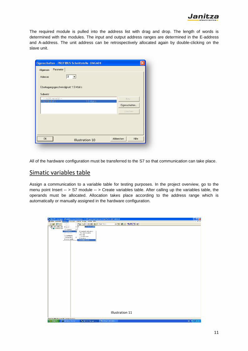
The required module is pulled into the address list with drag and drop. The length of words is
determined with the modules. The input and output address ranges are determined in the E-address
and A-address. The unit address can be retrospectively allocated again by double-clicking on the
slave unit.
All of the hardware configuration must be transferred to the S7 so that communication can take place.
Simatic variables table
Assign a communication to a variable table for testing purposes. In the project overview, go to the
menu point Insert -- > S7 module -- > Create variables table. After calling up the variables table, the
operands must be allocated. Allocation takes place according to the address range which is
automatically or manually assigned in the hardware configuration.
Illustration 10
Illustration 11

12
The following table shows the variables table with the explanation:
Operand Symbol Display Format Status value Control value Explanation
PAB 256 DEZ 0 Profile number
request
PEB 256 DEZ 0 Profile number
request
PED 257 Floating point 230.7 1st
value in profile
0 (ULN1)
PED 261 Floating point 230.5 2nd
value in
profile 0 (ULN2)
PED 265 Floating point 230.8 3rd
value in
profile 0 (ULN3)
PED 269 Floating point 8844.9 4th
value in
profile 0 (PSUM)
Output byte is
written
Live values are
activated
Illustration 12

13
The requested profile number is parameterised in the first output byte. This is given back as a
confirmation in the first input byte. If the exact profile number is not returned, the profile has not been
read or has not been parameterised in the unit. The measurement values are after the first input byte.
The spacing between the input and output bytes depends on the format. In the case of a float format,
the spacing would be 4 bytes. If another format has been selected in the profiles, the spacing can be
less (spacing = byte size of the format).
Profibus Profiles in Graphic Programming
The profibus function modules in graphic programming are available from GridVis 1.6.0 and Firmware
1.095 (UMG604). All measurement values and all variables defined by the user can be allocated to a
profile (profiles 16 - 255) using the graphic programming. The "write profibus" function module is used
for allocation. Profiles can also be read and analysed ("read profibus“). With the "read profibus"
function module, variables in the profile described by the PLC can be read and used in the programme
e.g. in order to set a digital output or reset a working value. There is an additional description of
functions for graphic programming. The Power Analyzer provides one profibus buffer for reading and
writing profile. If you want to change between difference profiles you could realised that with a
graphical function code “IF command”. Without IF command you could use only one reading and
one writing profile in processed (program)!
Example for the Write Profibus Profile
The graphic programming of a profibus profile is described in the following example. Three constants
(fixed values) are allocated to profile 16. The programme is processed in measurement intervals
(200ms).
Abbildung 13
14
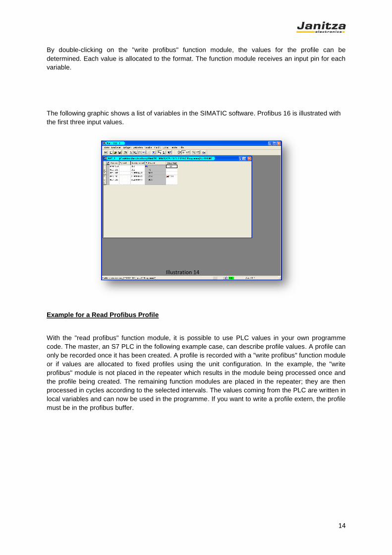
By double-clicking on the "write profibus" function module, the values for the profile can be
determined. Each value is allocated to the format. The function module receives an input pin for each
variable.
The following graphic shows a list of variables in the SIMATIC software. Profibus 16 is illustrated with
the first three input values.
Example for a Read Profibus Profile
With the "read profibus" function module, it is possible to use PLC values in your own programme
code. The master, an S7 PLC in the following example case, can describe profile values. A profile can
only be recorded once it has been created. A profile is recorded with a "write profibus" function module
or if values are allocated to fixed profiles using the unit configuration. In the example, the "write
profibus" module is not placed in the repeater which results in the module being processed once and
the profile being created. The remaining function modules are placed in the repeater; they are then
processed in cycles according to the selected intervals. The values coming from the PLC are written in
local variables and can now be used in the programme. If you want to write a profile extern, the profile
must be in the profibus buffer.
Illustration 14
15
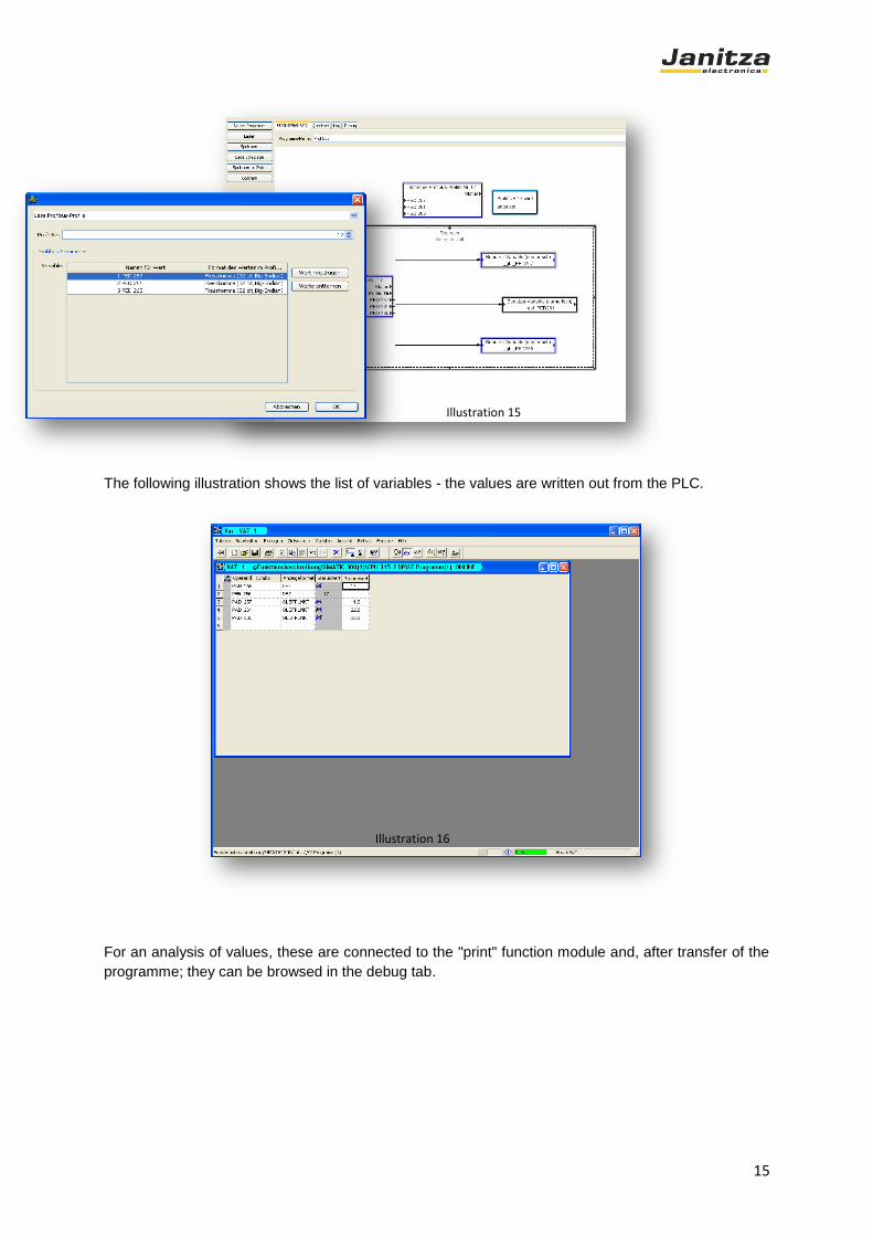
The following illustration shows the list of variables - the values are written out from the PLC.
For an analysis of values, these are connected to the "print" function module and, after transfer of the
programme; they can be browsed in the debug tab.
Illustration 15
Illustration 16

16
Status Analysis
Each profibus function module has a status pin that can be used for analysis. The following table
shows the error codes
Error no. Comment
-1 Error
0 No error
255 Feedback of the incorrect
profile number
Illustration 17
Illustration 19
17
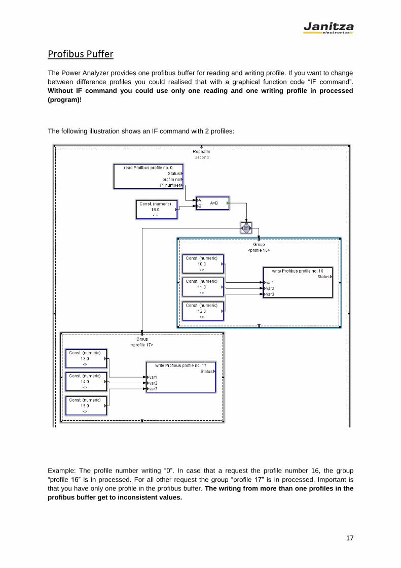
Profibus Puffer
The Power Analyzer provides one profibus buffer for reading and writing profile. If you want to change
between difference profiles you could realised that with a graphical function code “IF command”.
Without IF command you could use only one reading and one writing profile in processed
(program)!
The following illustration shows an IF command with 2 profiles:
Example: The profile number writing “0”. In case that a request the profile number 16, the group
“profile 16” is in processed. For all other request the group “profile 17” is in processed. Important is
that you have only one profile in the profibus buffer. The writing from more than one profiles in the
profibus buffer get to inconsistent values.
18
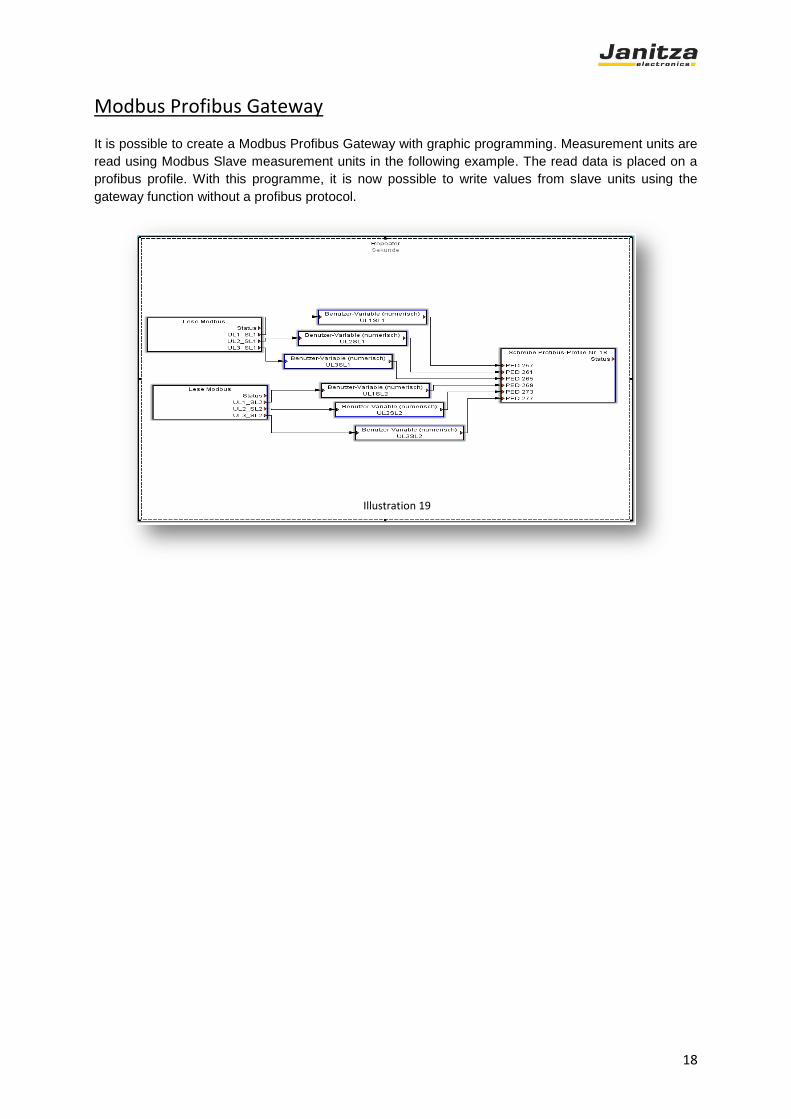
Modbus Profibus Gateway
It is possible to create a Modbus Profibus Gateway with graphic programming. Measurement units are
read using Modbus Slave measurement units in the following example. The read data is placed on a
profibus profile. With this programme, it is now possible to write values from slave units using the
gateway function without a profibus protocol.
Illustration 19