Embed Size (px)
Citation preview
Vibration Damping
Professor Mike Brennan

Vibration Control by Damping
• Review of damping mechanisms and effects of
damping
– Viscous
– Hysteretic
– Coulomb
• Modelling and characteristics of viscoelastic damping
• Application of constrained and unconstrained layer
damping
• Measurement of damping

Damping
• material damping (internal friction, mechanical hysteresis)
• friction at joints
• added layers of materials with high loss factors (e.g. visco-
elastic materials)
• hydraulic dampers (shock absorbers, hydromounts)
• air/oil pumping: squeeze-film damping
• impacts (conversion of energy into higher frequency vibration
which is then dissipated)
• acoustic radiation - vibration energy converted into sound (only
important for lightly damped structures or heavy fluid loading,
e.g. light plastic structures)
• structural ‘radiation’ - transport of vibration into adjacent
structures or fluids
dissipation of mechanical energy (usually conversion into heat)
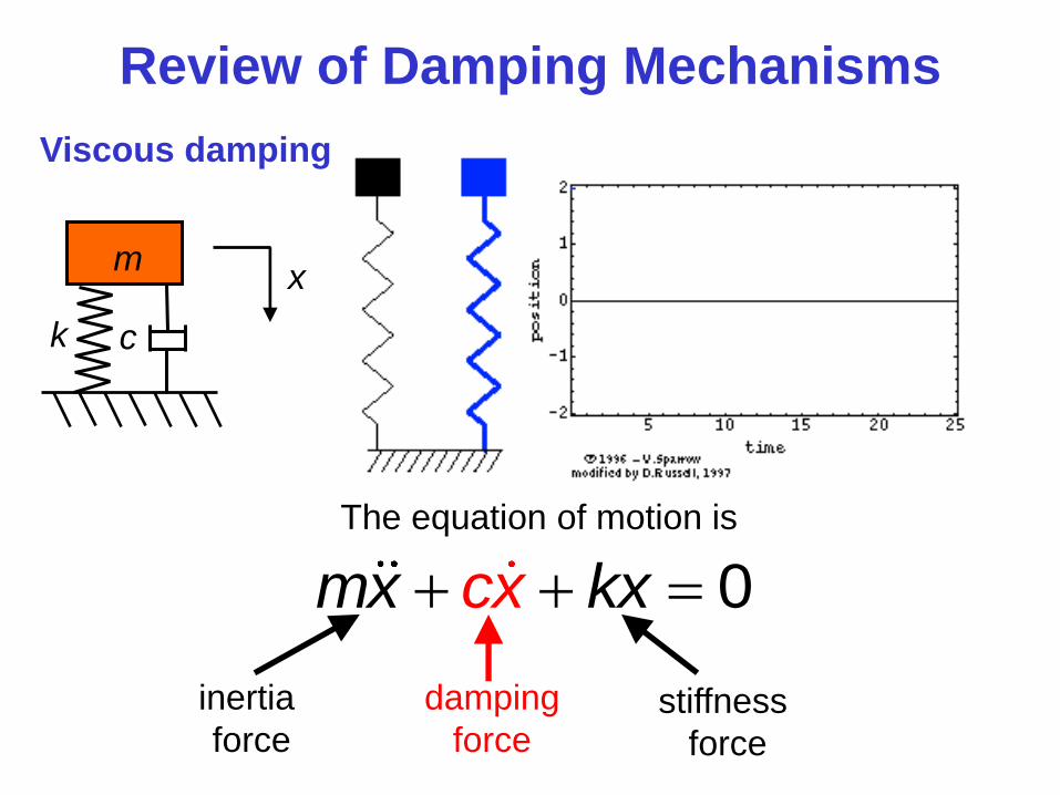
Review of Damping Mechanisms
Viscous damping
k
m x
c
The equation of motion is
0cx kxm x
inertia
force stiffness
force
damping
force
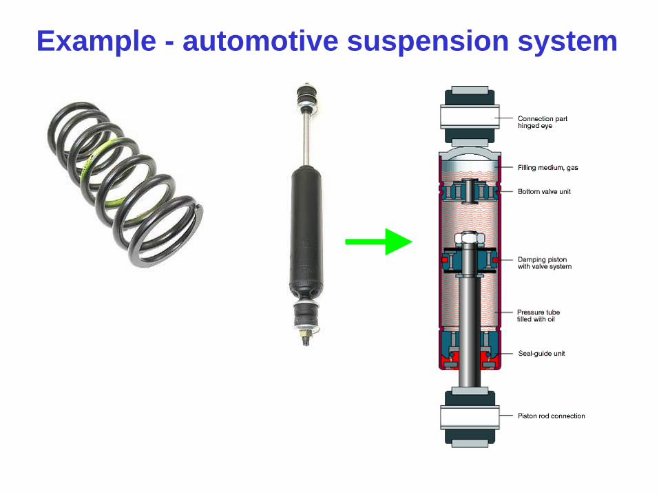
Example - automotive suspension system
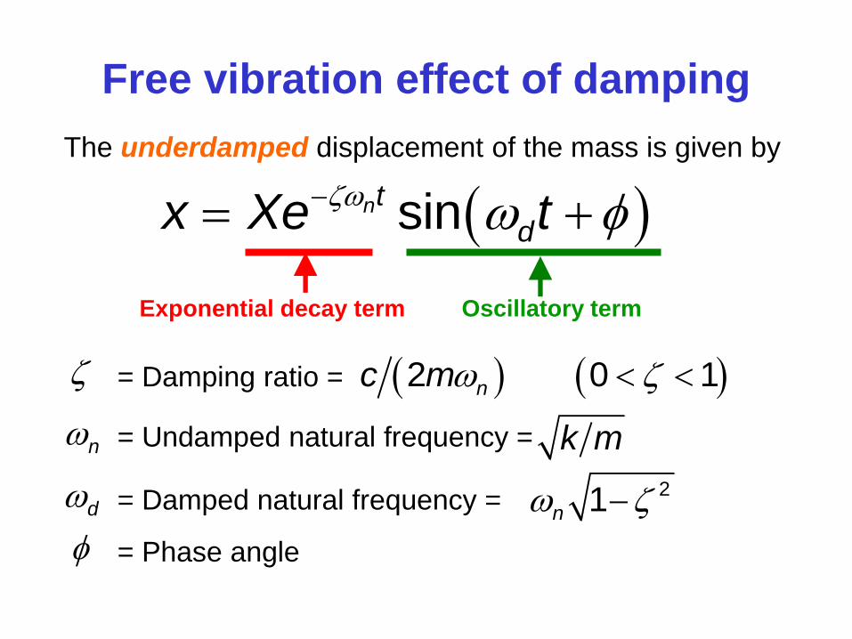
Free vibration effect of damping
The underdamped displacement of the mass is given by
sinnt
dx Xe t
= Damping ratio = 2 0 1nc m
n = Undamped natural frequency = k m
d = Damped natural frequency = 21n
= Phase angle
Exponential decay term Oscillatory term
ntx Xe
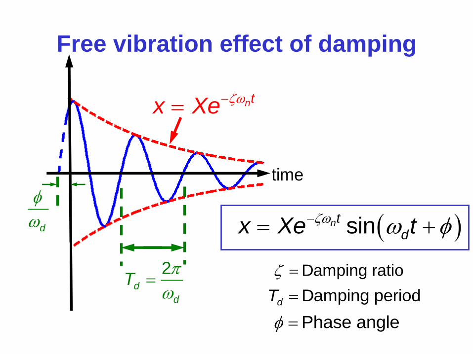
Free vibration effect of damping
time
2d
d
T
d
sinnt
dx Xe t
Damping ratio
Damping perioddT
Phase angle
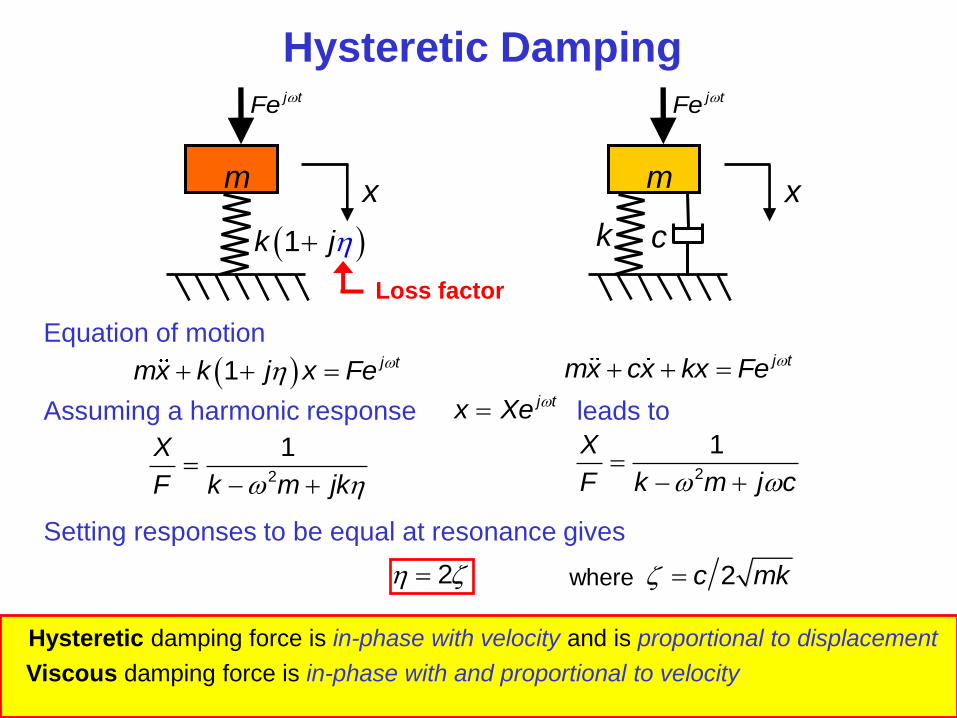
Hysteretic Damping
2
1X
F k m j c
k
m x
c
j tFe
m x
j tFe
1k j
Loss factor
Equation of motion
1 j tmx k j x Fe j tmx cx kx Fe
2
1X
F k m jk
Assuming a harmonic response leads to j tx Xe
Setting responses to be equal at resonance gives
Hysteretic damping force is in-phase with velocity and is proportional to displacement
Viscous damping force is in-phase with and proportional to velocity
2 where 2c mk
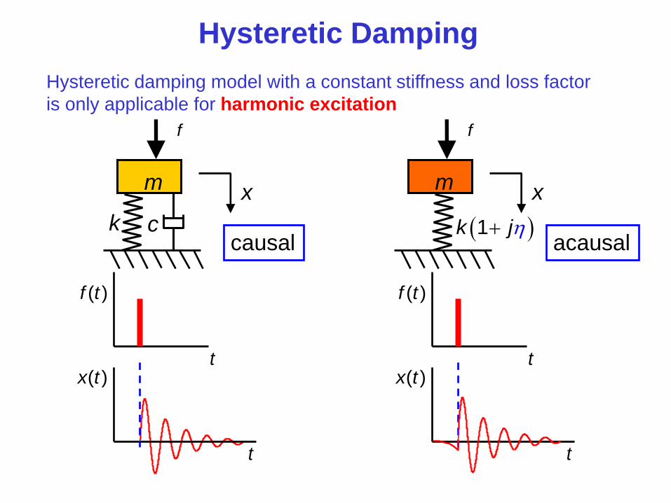
Hysteretic Damping
k
m x
c
f
m x
f
1k j
Hysteretic damping model with a constant stiffness and loss factor
is only applicable for harmonic excitation
( )f t
t
t
( )x t
( )f t
t
causal acausal
t
( )x t
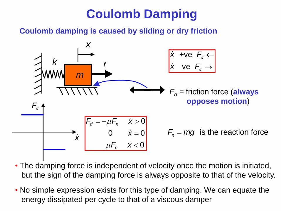
Coulomb Damping
Coulomb damping is caused by sliding or dry friction
k
m
x
f
Fd = friction force (always
opposes motion)
+ve
-ve
d
d
x F
x F
• The damping force is independent of velocity once the motion is initiated,
but the sign of the damping force is always opposite to that of the velocity.
• No simple expression exists for this type of damping. We can equate the
energy dissipated per cycle to that of a viscous damper
dF
x
0
0 0
0
d n
n
F F x
x
F x
is the reaction forcenF mg

How to compare damping mechanisms?
Energy dissipated by a viscous damper
x
c dF
dF cx
Energy lost per cycle is
work done = force distanceE
0
T
d d
dxE F dx F dt
dt
Now if
sinx X t
then cosx X t
2
2
0
E cx dt
(1)
2
2 2 2
0
cosE c X t dt
Substitute into (1) gives
which evaluates to give
2 E c X
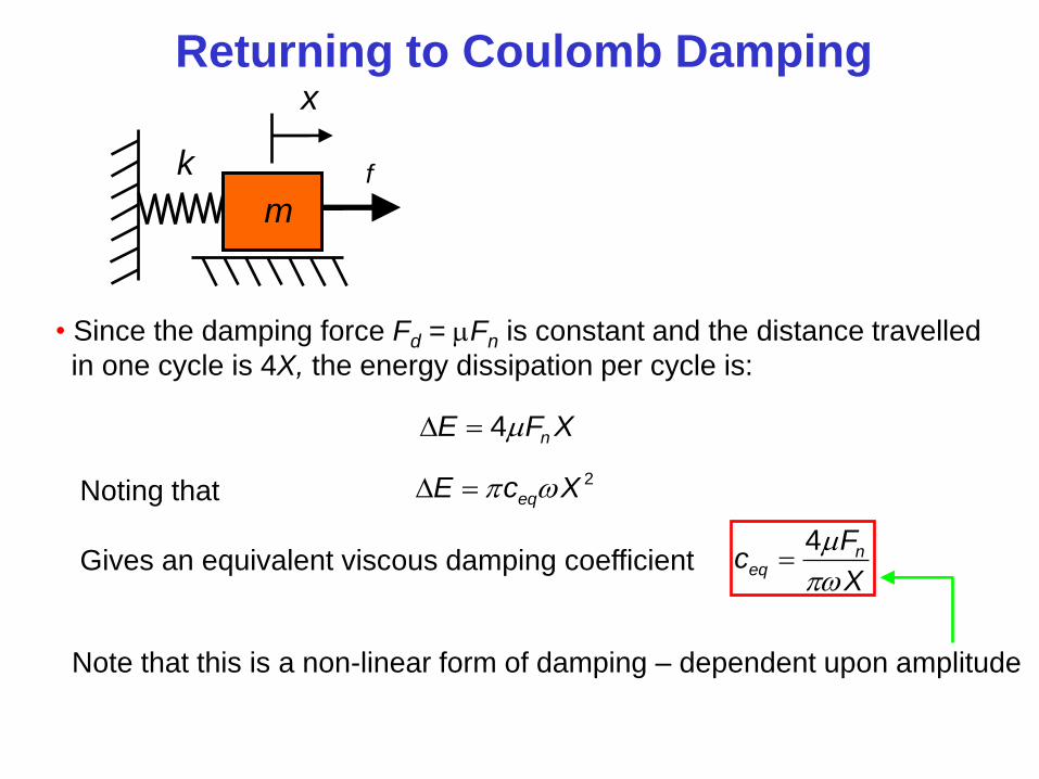
Returning to Coulomb Damping
k
m
x
f
• Since the damping force Fd = Fn is constant and the distance travelled
in one cycle is 4X, the energy dissipation per cycle is:
4 nE F X
Noting that 2
eqE c X
Gives an equivalent viscous damping coefficient 4 n
eq
Fc
X
Note that this is a non-linear form of damping – dependent upon amplitude
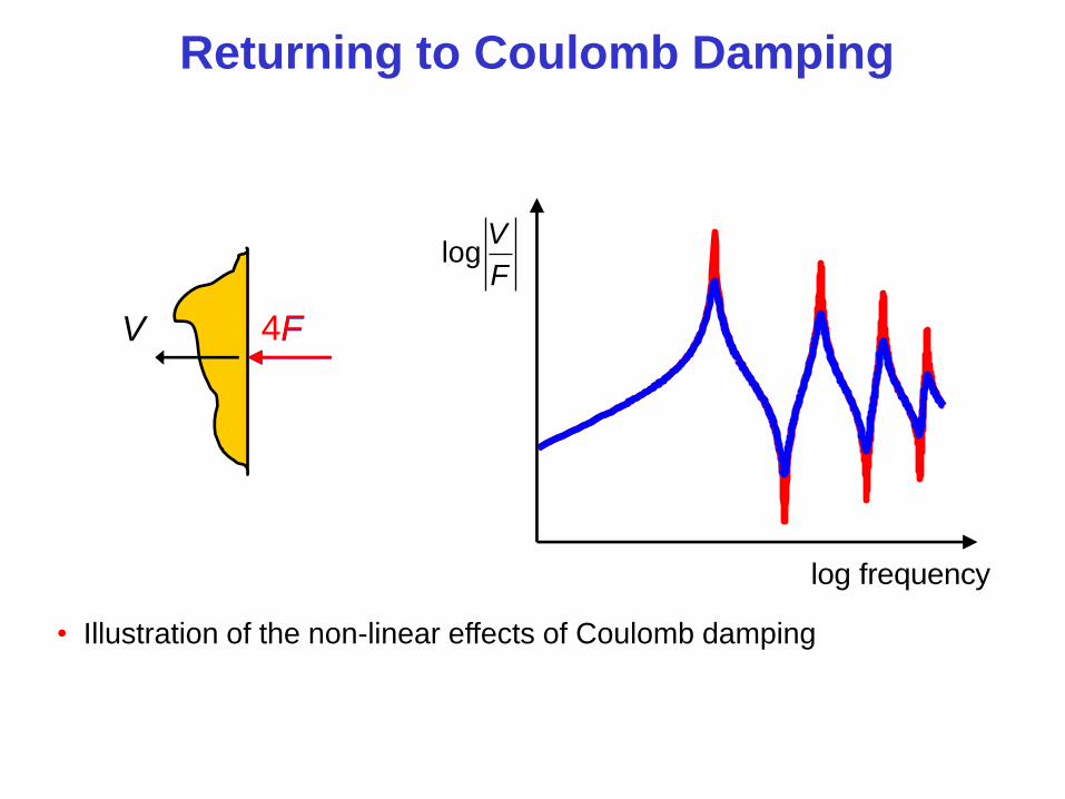
Returning to Coulomb Damping
log frequency
logV
F
F 4F V
• Illustration of the non-linear effects of Coulomb damping
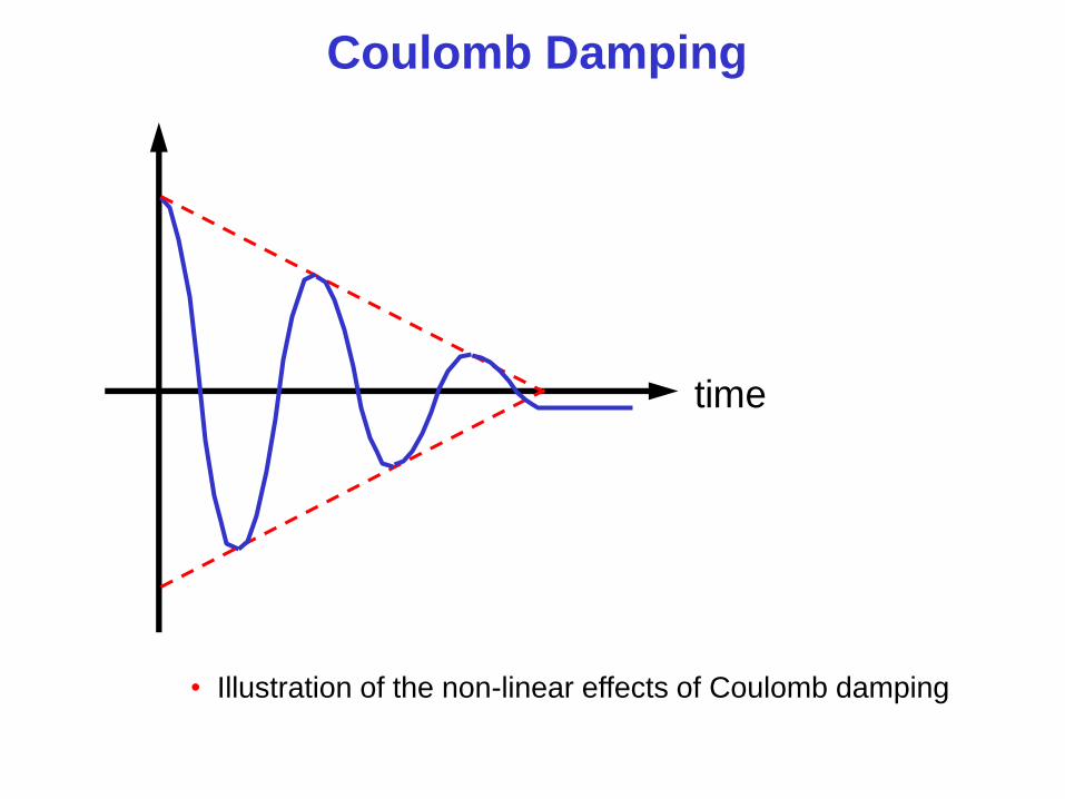
Coulomb Damping
• Illustration of the non-linear effects of Coulomb damping
time

Equivalent viscous damping forces
and coefficients
Damping
Mechanism
Damping Force Equivalent
Viscous
Damping
Viscous
Hysteretic
Coulomb
cx
k x
nF
c
k
4 nF
X
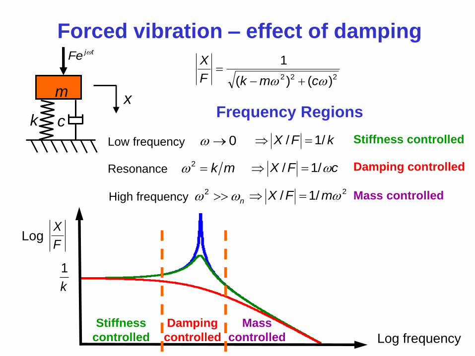
Forced vibration – effect of damping
Log frequency
Log
1
k
k
m x
c
j tFe
Frequency Regions
222 )()(
1
cmkF
X
F
X
Low frequency 0 Stiffness controlled
Stiffness
controlled
kFX /1/
Resonance 2 k m Damping controlled
Damping
controlled
cFX /1/
High frequency 2
n Mass controlled
Mass
controlled
2/1/ mFX
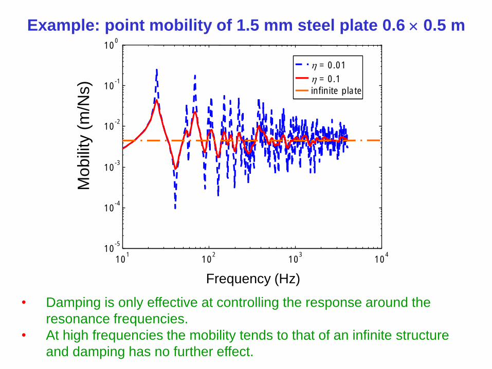
Example: point mobility of 1.5 mm steel plate 0.6 0.5 m
= 0.01
= 0.1
infinite plate
10 1
10 2
10 3
10 4
10 -5
10 -4
10 -3
10 -2
10 -1
10 0
Frequency (Hz)
Mo
bili
ty (
m/N
s)
• Damping is only effective at controlling the response around the
resonance frequencies.
• At high frequencies the mobility tends to that of an infinite structure
and damping has no further effect.
Visco-elastic materials
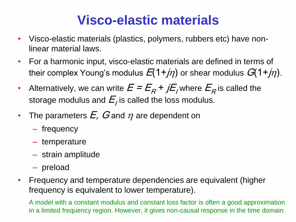
• Visco-elastic materials (plastics, polymers, rubbers etc) have non-
linear material laws.
• For a harmonic input, visco-elastic materials are defined in terms of
their complex Young’s modulus E(1+j) or shear modulus G(1+j).
• Alternatively, we can write E = ER + jEI where ER is called the
storage modulus and EI is called the loss modulus.
• The parameters E, G and are dependent on
– frequency
– temperature
– strain amplitude
– preload
• Frequency and temperature dependencies are equivalent (higher
frequency is equivalent to lower temperature).
A model with a constant modulus and constant loss factor is often a good approximation
in a limited frequency region. However, it gives non-causal response in the time domain
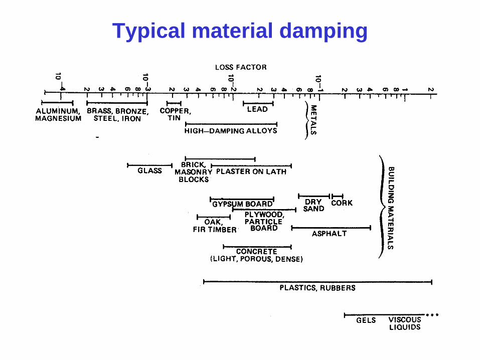
Typical material damping
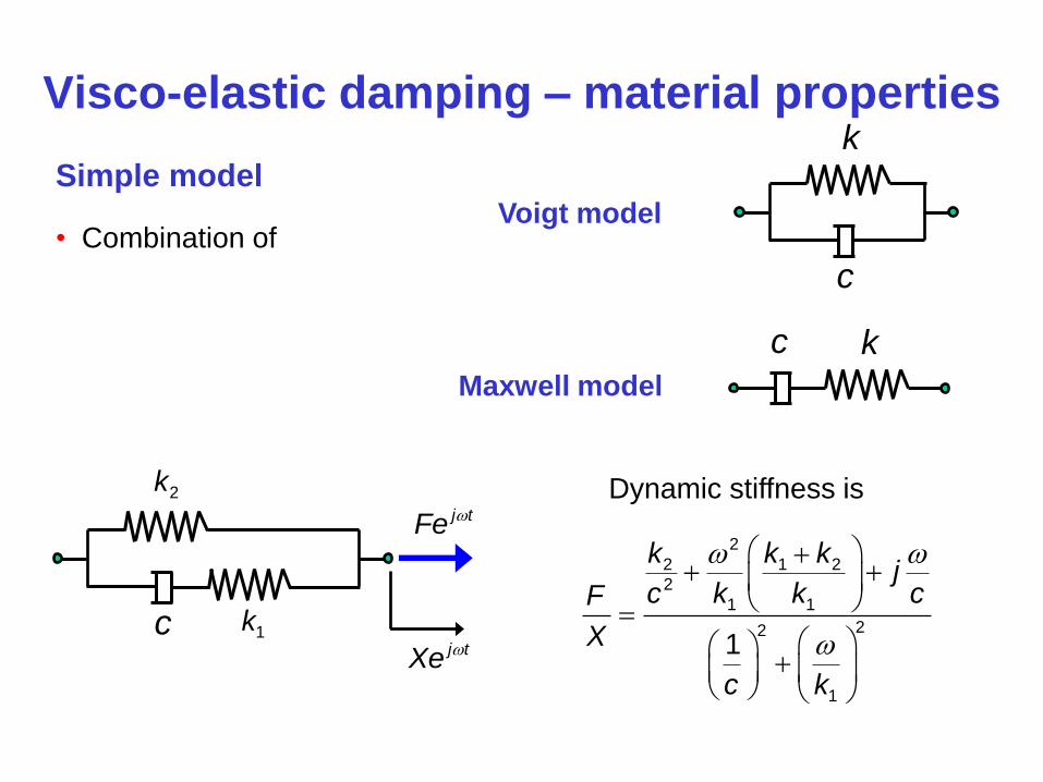
Visco-elastic damping – material properties
Simple model
• Combination of Voigt model
Maxwell model
k c
k
c
c
2k
1k
j tFe
j tXe
Dynamic stiffness is
2
2 1 2
2
1 1
22
1
1
k k kj
c k k cF
X
c k
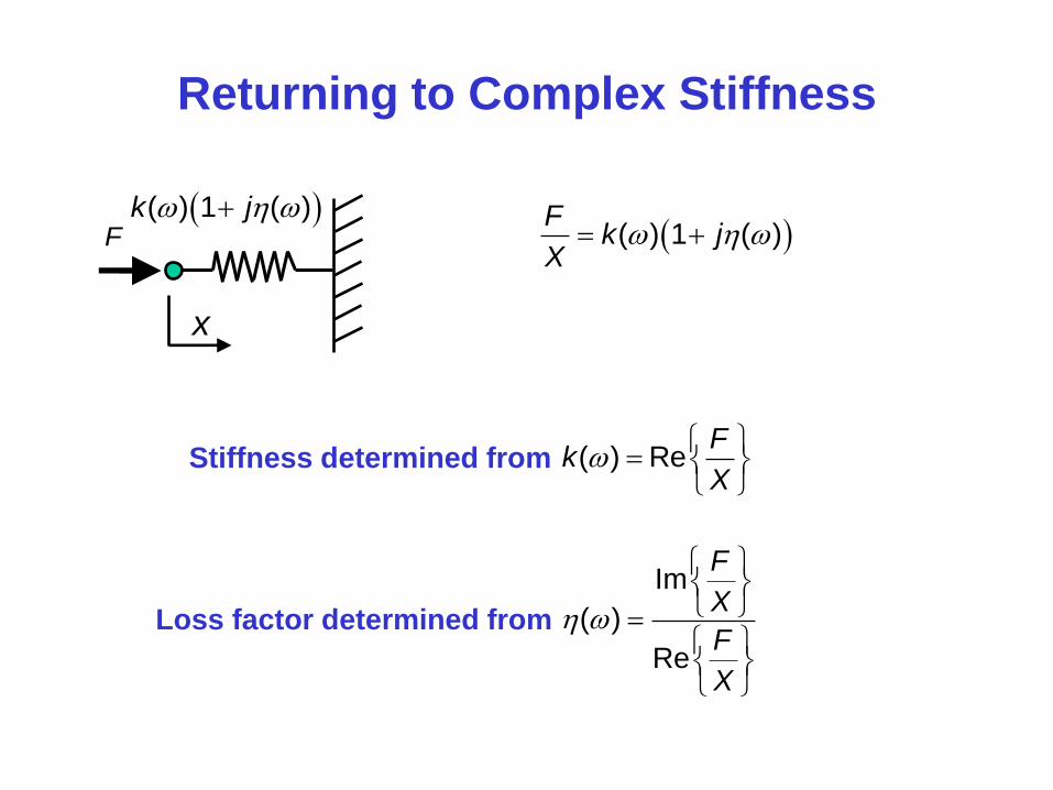
Returning to Complex Stiffness
x
F ( ) 1 ( )k j
( ) 1 ( )F
k jX
Stiffness determined from ( ) ReF
kX
Loss factor determined from
Im
( )
Re
F
X
F
X
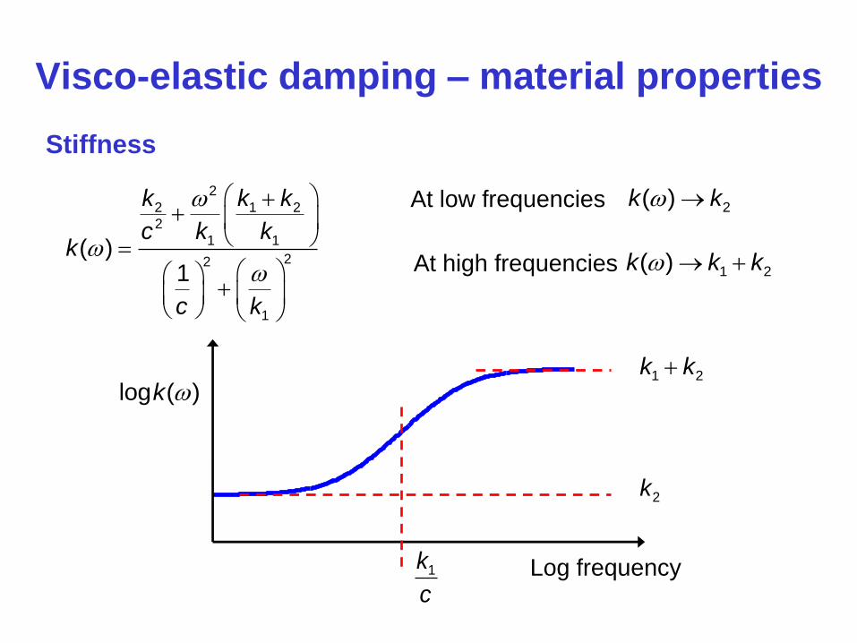
Visco-elastic damping – material properties
Stiffness
2
2 1 2
2
1 1
22
1
( )1
k k k
c k kk
c k
Log frequency
log ( )k
At low frequencies 2( )k k
2k
At high frequencies 1 2( )k k k
1 2k k
1k
c

Visco-elastic damping – material properties
Loss factor
2
2 1 2
2
1 1
( ) c
k k k
c k k
Log frequency
log ( )
1k
c
At low frequencies 2
( )c
k
At high frequencies 1 2
1 1
1( )
c k k
k k
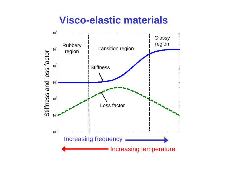
Visco-elastic materials
10 -2
10 -1
10 0
10 1
10 2
10 3
10 4
Transition region
Glassy
region
Loss factor
Stiffness
Stiffn
ess a
nd
lo
ss fa
cto
r
Increasing frequency
Increasing temperature
Rubbery
region
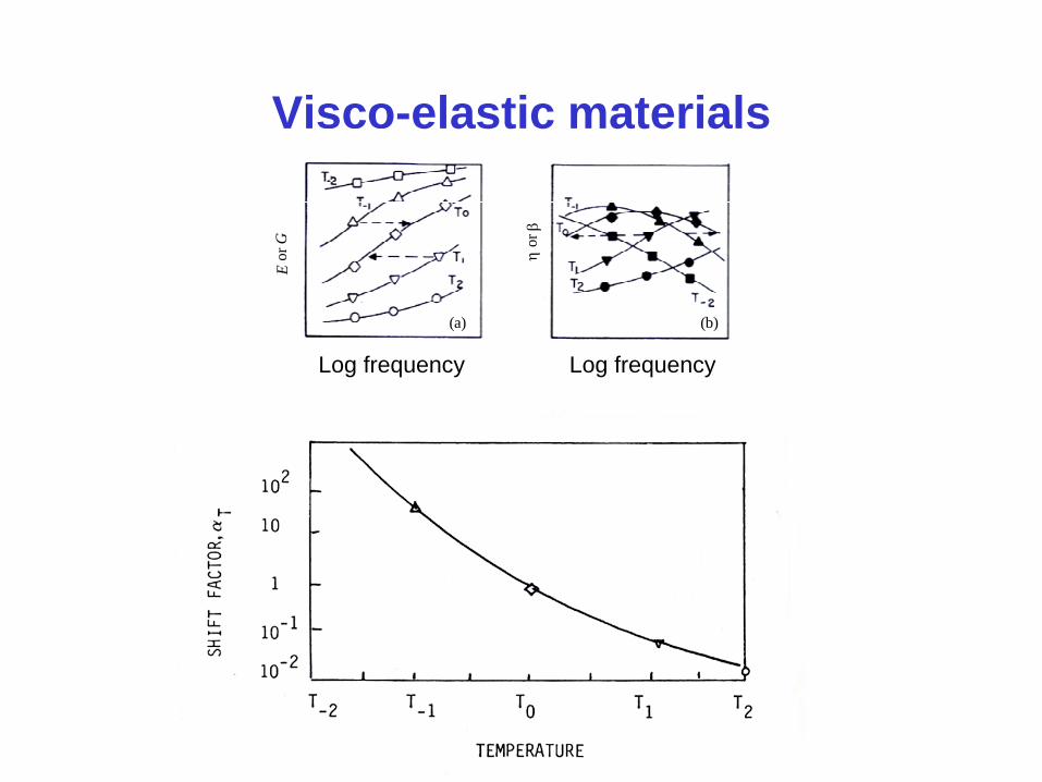
Visco-elastic materials
Log frequency Log frequency
E o
r G
o
r
(a) (b)
Log frequency Log frequency

Visco-elastic materials – reduced
frequency nomogram
frequency
f, (
Hz)
modulu
s E
and loss f
acto
r η
reduced frequency fαT, Hz
temperature
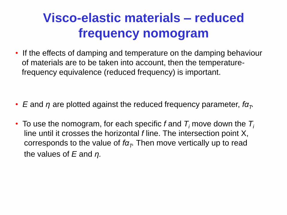
Visco-elastic materials – reduced
frequency nomogram
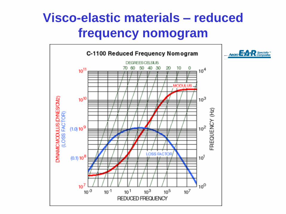
• If the effects of damping and temperature on the damping behaviour
of materials are to be taken into account, then the temperature-
frequency equivalence (reduced frequency) is important.
• E and η are plotted against the reduced frequency parameter, fαT.
• To use the nomogram, for each specific f and Ti move down the Ti
line until it crosses the horizontal f line. The intersection point X,
corresponds to the value of fαT. Then move vertically up to read
the values of E and η.
Visco-elastic materials – reduced
frequency nomogram

Visco-elastic materials and damping
treatments
Modulu
s o
r lo
ss f
acto
r
Temperature
• For damping treatments visco-elastic materials should generally be used in their
transition region, where the loss factor is highest. However small changes in
temperature can have a large change in stiffness.
Useful range for
damping treatments
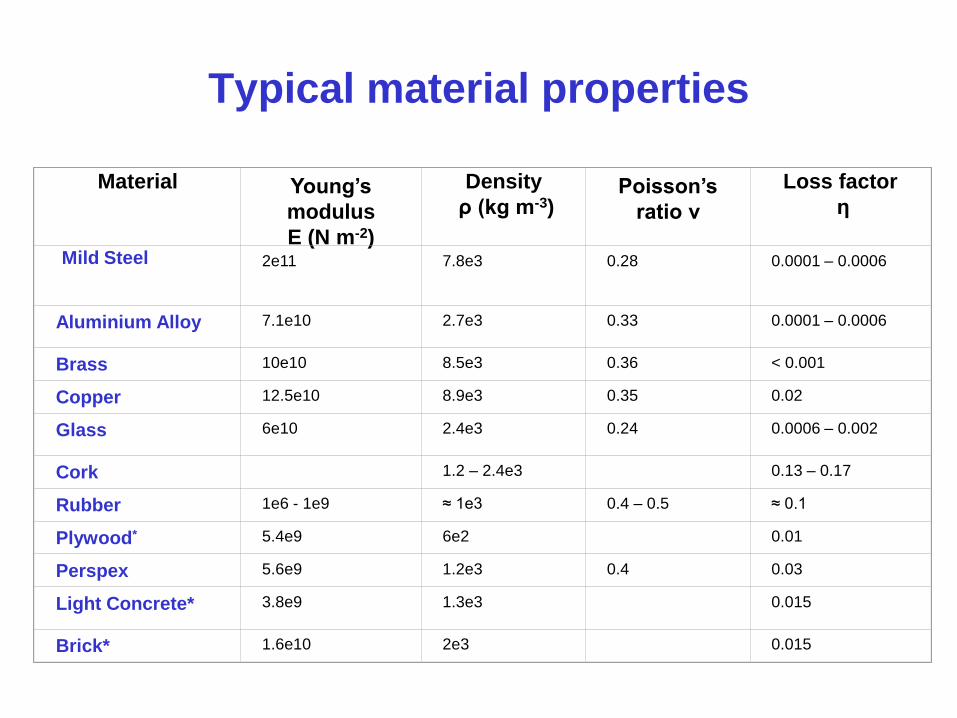
Typical material properties
Material
Young’s
modulus
E (N m-2)
Density
ρ (kg m-3)
Poisson’s
ratio ν
Loss factor
η
Mild Steel
2e11
7.8e3
0.28
0.0001 – 0.0006
Aluminium Alloy
7.1e10
2.7e3
0.33
0.0001 – 0.0006
Brass
10e10
8.5e3
0.36
< 0.001
Copper
12.5e10
8.9e3
0.35
0.02
Glass
6e10
2.4e3
0.24
0.0006 – 0.002
Cork
1.2 – 2.4e3
0.13 – 0.17
Rubber
1e6 - 1e9
≈ 1e3
0.4 – 0.5
≈ 0.1
Plywood*
5.4e9
6e2
0.01
Perspex
5.6e9
1.2e3
0.4
0.03
Light Concrete*
3.8e9
1.3e3
0.015
Brick*
1.6e10
2e3
0.015

Damping treatments using visco-
elastic materials

Viscoelastic damper
Viscoelastic
material
Damping treatments using visco-elastic
materials
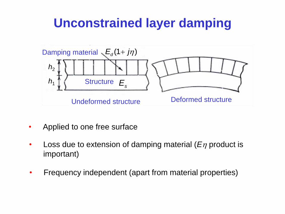
Unconstrained layer damping
h2
h1
(1 )dE j
sE
• Applied to one free surface
• Loss due to extension of damping material (E product is
important)
• Frequency independent (apart from material properties)
Undeformed structure Deformed structure
Structure
Damping material
Unconstrained layer damping
h2
h1
(1 )dE j
sE
Undeformed structure Deformed structure
Structure
Damping material
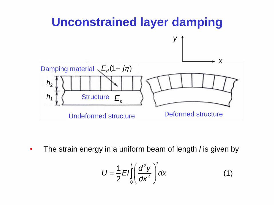
• The strain energy in a uniform beam of length l is given by
22
2
0
1
2
ld y
U EI dxdx
x
y
(1)

Unconstrained layer damping
• A definition of the loss factor is
1 energy dissipated per cycle
2 maximum energy stored per cycle
Let loss factor for the structureb composite
Let loss factor for the d damping layer
Assume that the loss factor in the structure is negligible compared
with the damping layer
energy dissipated per cycle in the structure
maximum energy stored per cycle in the structureb
d
composite
composite
energy dissipated per cycle in the
maximum energy stored per cycle in the
damping layer
damping layer
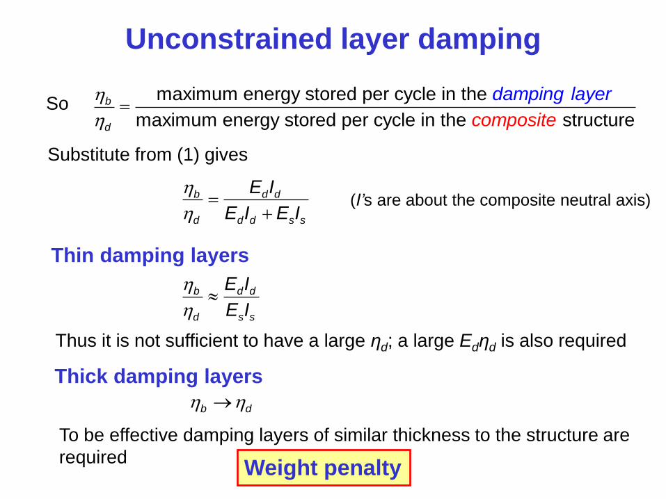
Unconstrained layer damping
So maximum energy stored per cycle in the
maximum energy stored per cycle in the struct u
reb
d composit
dampin l
e
g ayer
Substitute from (1) gives
b d d
d d d s s
E I
E I E I
(I’s are about the composite neutral axis)
Thin damping layers
b d d
d s s
E I
E I
Thus it is not sufficient to have a large ηd; a large Edηd is also required
Thick damping layers
b d
To be effective damping layers of similar thickness to the structure are
required Weight penalty
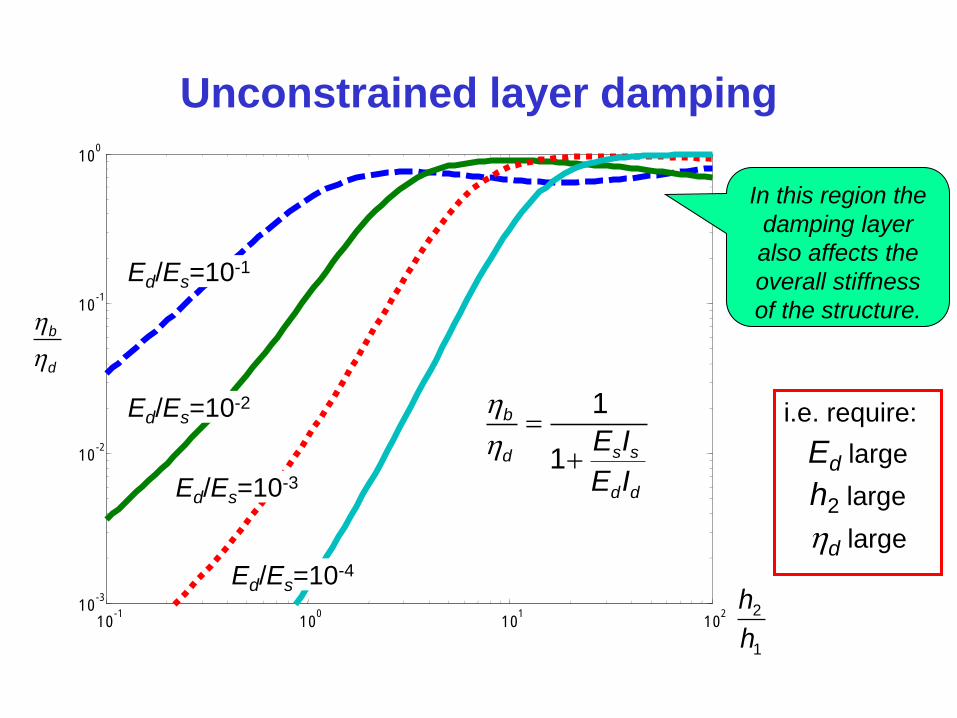
Unconstrained layer damping
10 -1
10 0
10 1
10 2
10 -3
10 -2
10 -1
10 0
c
b
d
2
1
h
h
1
1
b
s sd
d d
E I
E I
Ed/Es=10-1
Ed/Es=10-2
Ed/Es=10-3
Ed/Es=10-4
i.e. require:
Ed large
h2 large
d large
In this region the
damping layer
also affects the
overall stiffness
of the structure.
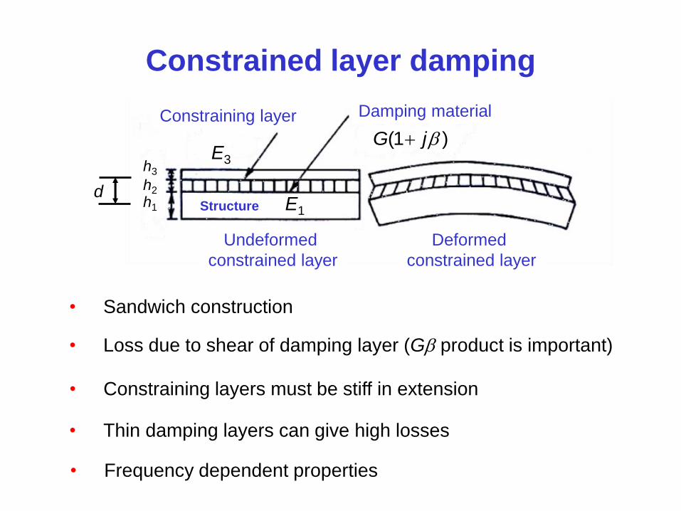
Constrained layer damping
• Sandwich construction
• Loss due to shear of damping layer (G product is important)
• Constraining layers must be stiff in extension
• Thin damping layers can give high losses
h3
h2
h1
d
(1 )G j
Damping material Constraining layer
Undeformed
constrained layer
Deformed
constrained layer
Structure E1
E3
• Frequency dependent properties
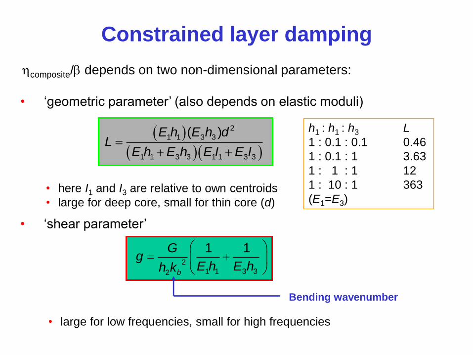
Constrained layer damping
2
1 1 3 32
1 1
b
Gg
E h E hh k
Bending wavenumber
2
1 1 3 3
1 1 3 3 1 1 3 3
( )E h E h dL
E h E h E I E I
composite/ depends on two non-dimensional parameters:
• ‘geometric parameter’ (also depends on elastic moduli)
• here I1 and I3 are relative to own centroids
• large for deep core, small for thin core (d)
• ‘shear parameter’
• large for low frequencies, small for high frequencies
h1 : h1 : h3 L
1 : 0.1 : 0.1 0.46
1 : 0.1 : 1 3.63
1 : 1 : 1 12
1 : 10 : 1 363
(E1=E3)

Constrained layer damping
10 -2
10 -1
10 0
10 1
10 2
10 -4
10 -3
10 -2
10 -1
10 0
L=100
L=10
L=0.1
L=1
2
1 1 3 32
1 1
b
Gg
E h E hh k
2
1 1 3 3
1 1 3 3 1 1 3 3
( )E h E h dL
E h E h E I E I
Shear parameter
composite
In this region
large L means
much stiffer
structure
Constrained layer damping
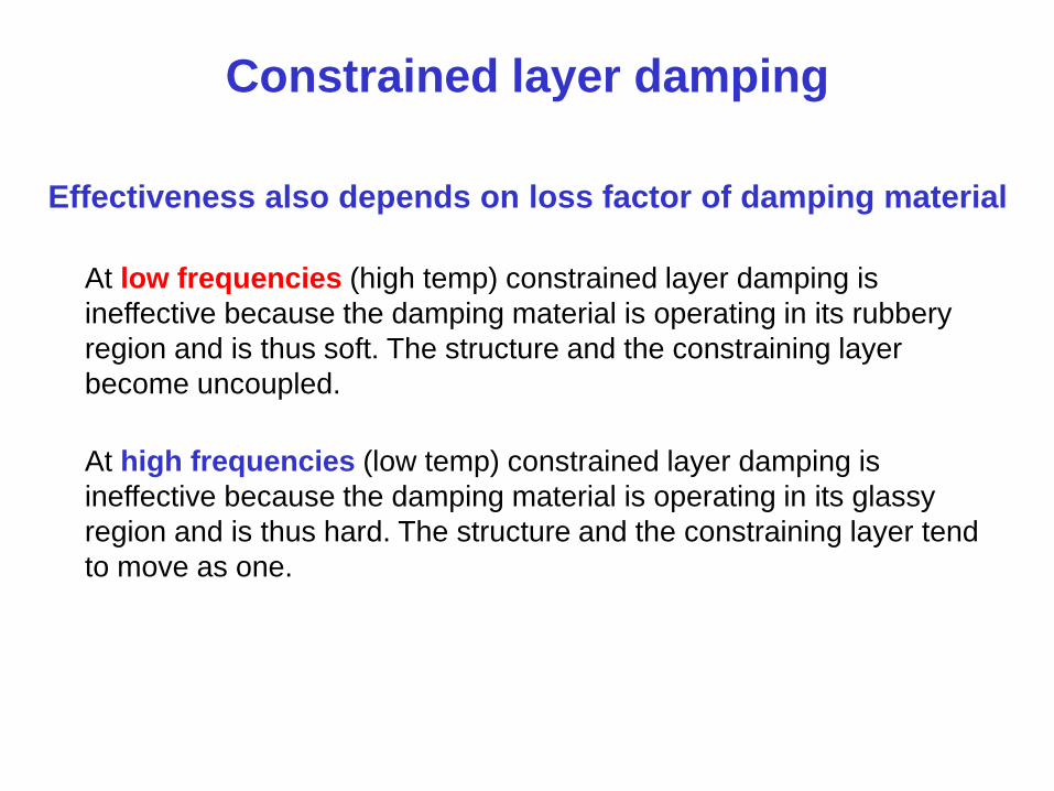
At low frequencies (high temp) constrained layer damping is
ineffective because the damping material is operating in its rubbery
region and is thus soft. The structure and the constraining layer
become uncoupled.
Effectiveness also depends on loss factor of damping material
At high frequencies (low temp) constrained layer damping is
ineffective because the damping material is operating in its glassy
region and is thus hard. The structure and the constraining layer tend
to move as one.

Other types of damping
Damping by air pumping
j tFe
Viscous damping
– reduces in effectiveness
at high frequencies
Pumping along joints
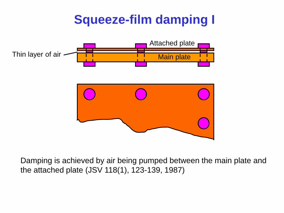
Squeeze-film damping I
Main plate
Attached plate
Thin layer of air
Damping is achieved by air being pumped between the main plate and
the attached plate (JSV 118(1), 123-139, 1987)
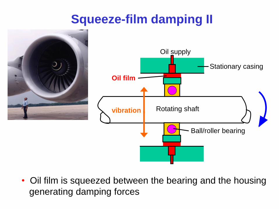
Squeeze-film damping II
Stationary casing
Rotating shaft
Ball/roller bearing
Oil film
Oil supply
vibration
• Oil film is squeezed between the bearing and the housing
generating damping forces
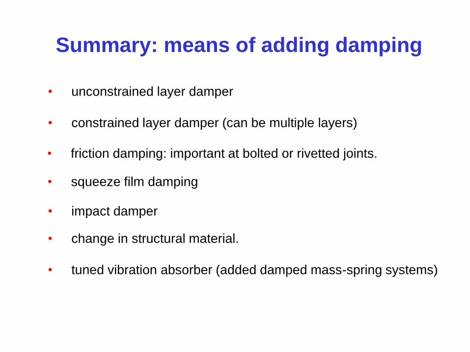
Summary: means of adding damping
• unconstrained layer damper
• constrained layer damper (can be multiple layers)
• squeeze film damping
• friction damping: important at bolted or rivetted joints.
• impact damper
• change in structural material.
• tuned vibration absorber (added damped mass-spring systems)
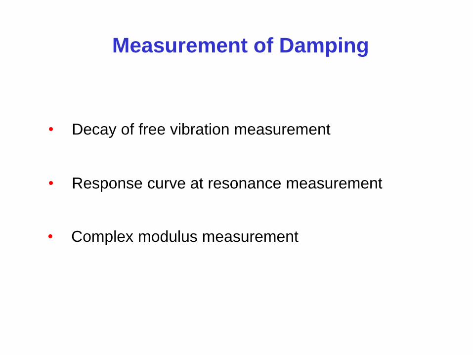
Measurement of Damping
• Decay of free vibration measurement
• Response curve at resonance measurement
• Complex modulus measurement

Measurement of Damping –decay of
free vibration
ntx Xe
t
x t
2
2 2
1d
d n
T
1t 2 1 dt t T
1x
2x
1
2
n dTxe
x
Measure the amplitude
of two successive cycles
1
2
ln n d
xT
x
Logarithmic decrement
So 2
2
1
For light damping 2
So 2
measured
Measurement of Damping – decay of
free vibration
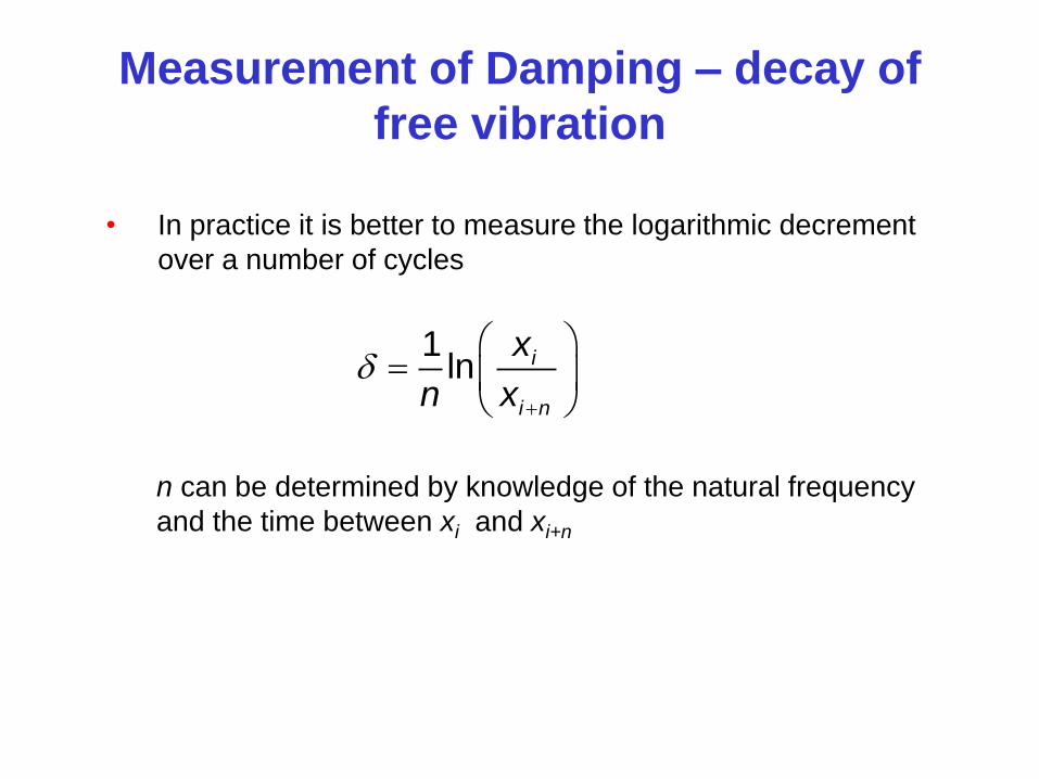
• In practice it is better to measure the logarithmic decrement
over a number of cycles
1ln i
i n
x
n x
n can be determined by knowledge of the natural frequency
and the time between xi and xi+n
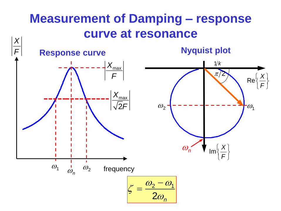
Measurement of Damping – response
curve at resonance
1 2n
X
F
maxX
F
max
2
X
F
frequency
Response curve
ReX
F
ImX
F
n
2
1 k
12
Nyquist plot
2 1
2 n
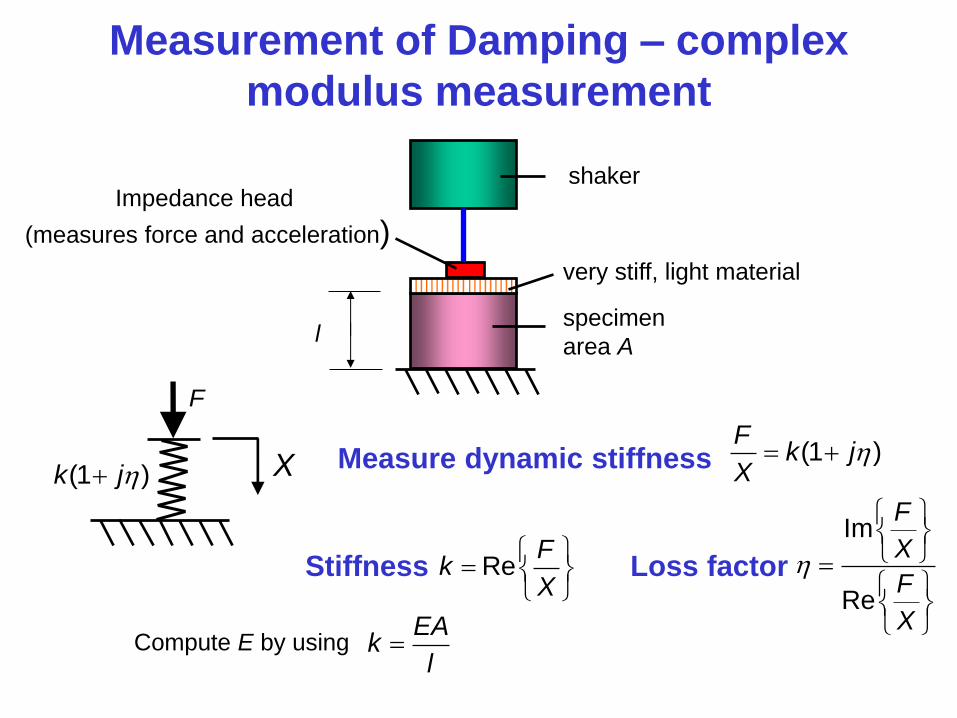
Measurement of Damping – complex
modulus measurement
shaker
specimen
area A
very stiff, light material
Impedance head
(measures force and acceleration)
l
X
F
(1 )k jMeasure dynamic stiffness (1 )
Fk j
X
Stiffness ReF
kX
Loss factor
Im
Re
F
X
F
X
Compute E by using EA
kl
Summary
• Review of damping mechanisms
• Modelling and characteristics of viscoelastic
damping
• Application of damping treatments
• Measurement of damping

References
• A.D. Nashif, D.I.G. Jones and J.P. Henderson, 1985, Vibration
Damping, John Wiley and Sons Inc.
• C.M. Harris, 1987, Shock and Vibration Handbook, Third
Edition, McGraw Hill.
• L.L. Beranek and I.L. Ver, 1992. Noise and Vibration Control
Engineering, John Wiley and Sons.
• D.J. Mead, 1999, Passive Vibration Control, John Wiley and
Sons.
• F.J. Fahy and J.G. Walker, 2004, Advanced Applications in
Acoustics, Noise and Vibration, Spon Press (chapter 12
Vibration Control by M.J. Brennan and N.S. Ferguson).
• F.S. Tse, I.E. Morse and R.T. Hinkle, 1978, Mechanical
Vibrations, Theory and Applications, Second Edition, Allyn and
Bacon, Inc.


![Ramsey Theory in the Work of Paul Erd}os · improvements by R odl, Thomason [122] and nally by Conlon [17]. The current best upper bound (for k = `) is 2 k k k C log k log log k:](https://img.pdfslide.us/doc/110x75/60dd7d68077c115a5c23a15e/ramsey-theory-in-the-work-of-paul-erdos-improvements-by-r-odl-thomason-122-and.jpg)


![Put x = H.C.F. (3, 2 × 6) = H.C.F. (3, 6) [True] · log x = 40 × 0.301 log x = 12.04 log 13 ≅ 12.04 ... = 7 ½ days S31.Ans() Sol. ... (x² + 4x + 4) = x](https://img.pdfslide.us/doc/110x75/5bf9069409d3f2ac7c8cbae5/put-x-hcf-3-2-6-hcf-3-6-true-log-x-40-0301-log-x.jpg)