Embed Size (px)
Citation preview
Professional Surveillance System User’s Manual
Version 4.06
i
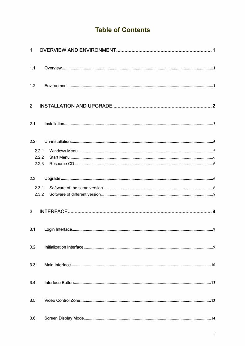
Table of Contents
1 OVERVIEW AND ENVIRONMENT ..................................................................... 1
1.1 Overview ........................................................................................................................................... 1
1.2 Environment ..................................................................................................................................... 1
2 INSTALLATION AND UPGRADE ....................................................................... 2
2.1 Installation......................................................................................................................................... 2
2.2 Un-installation ................................................................................................................................... 5
2.2.1 Windows Menu ............................................................................................................................ 5
2.2.2 Start Menu.................................................................................................................................... 6
2.2.3 Resource CD ............................................................................................................................... 6
2.3 Upgrade ............................................................................................................................................ 6
2.3.1 Software of the same version ..................................................................................................... 6
2.3.2 Software of different version ....................................................................................................... 8
3 INTERFACE ........................................................................................................ 9
3.1 Login Interface.................................................................................................................................. 9
3.2 Initialization Interface ....................................................................................................................... 9
3.3 Main Interface ................................................................................................................................. 10
3.4 Interface Button .............................................................................................................................. 12
3.5 Video Control Zone ........................................................................................................................ 13
3.6 Screen Display Mode ..................................................................................................................... 14
ii
3.7 Function Button .............................................................................................................................. 14
3.7.1 Task ............................................................................................................................................ 14
3.7.2 Alarm Record ............................................................................................................................. 15
3.7.2.1 Alarm Record .................................................................................................................... 15
3.7.3 Playback ..................................................................................................................................... 18
3.7.3.1 Device Record .................................................................................................................. 18
3.7.3.2 Link Record (Activation Record)...................................................................................... 19
3.7.3.3 Local Record ..................................................................................................................... 21
3.7.3.4 Download .......................................................................................................................... 22
3.7.3.5 Dav to Avi .......................................................................................................................... 23
3.7.4 E-map ......................................................................................................................................... 24
3.7.5 Configuration.............................................................................................................................. 28
3.7.5.1 Password Modification ..................................................................................................... 28
3.7.5.2 Option ................................................................................................................................ 29
3.7.6 Device Preview Output Config.................................................................................................. 31
3.8 Right Tool Bar ................................................................................................................................ 34
3.8.1 Device List.................................................................................................................................. 34
3.8.1.1 Device list main interface ................................................................................................. 34
3.8.1.2 NVD operation .................................................................................................................. 35
3.8.1.3 General device operation ................................................................................................. 37
3.8.1.4 NVD operation .................................................................................................................. 41
3.8.1.5 Non-real-time channel node and real-time channel node ............................................. 41
3.8.1.6 Real-time monitor ............................................................................................................. 46
3.8.2 PTZ Direction Control ................................................................................................................ 47
3.8.3 PTZ Advanced ........................................................................................................................... 48
3.8.4 Tool s .......................................................................................................................................... 51
3.8.4.1 Begin/Stop record plan .................................................................................................... 51
3.8.4.2 NVD Control ...................................................................................................................... 51
3.8.4.3 Health Report .................................................................................................................... 56
3.8.4.4 Log Search ........................................................................................................................ 57
3.8.4.5 Alarm Link Video (Alarm Activation Video) ..................................................................... 58
3.8.4.6 Alarm Output Control ....................................................................................................... 60
3.8.4.7 Color Configuration .......................................................................................................... 60
3.8.4.8 Volume .............................................................................................................................. 60
3.8.5 Setting Manage.......................................................................................................................... 61
3.8.5.1 Scheme and Task (Task and Project) ............................................................................ 61
3.8.5.2 Record Plan Configuration............................................................................................... 65
3.8.5.3 Alarm Manage .................................................................................................................. 67
3.8.5.4 Alarm Record Plan ........................................................................................................... 73
3.8.5.5 E-map ................................................................................................................................ 75
3.8.5.6 Decode Card Configuration ............................................................................................. 79
3.8.5.7 User Management ............................................................................................................ 81
3.8.5.8 Device Manage ................................................................................................................. 82
iii
3.8.5.9 NVD Manage .................................................................................................................... 84
3.8.5.10 SNVD Manage .................................................................................................................. 84
3.8.5.11 Extension Screen ............................................................................................................. 85
3.8.5.12 User Configuration ........................................................................................................... 90
3.9 Device Health Status ..................................................................................................................... 90
3.10 Full Menu ........................................................................................................................................ 91
3.10.1 Modify Password ................................................................................................................... 91
3.10.2 Device .................................................................................................................................... 91
3.10.3 Alarm ...................................................................................................................................... 92
3.10.4 Record Manage ..................................................................................................................... 92
3.10.5 Scheme Task ........................................................................................................................ 93
3.10.6 E-map .................................................................................................................................... 93
3.10.7 Configuration ......................................................................................................................... 93
3.10.8 Log Query .............................................................................................................................. 94
3.10.9 Log out ................................................................................................................................... 94
3.10.10 Exit ......................................................................................................................................... 94
3.11 Tray Menu....................................................................................................................................... 95
3.11.1 Modify Password ................................................................................................................... 95
3.11.2 Alarm ...................................................................................................................................... 95
3.11.3 E-map View ........................................................................................................................... 95
3.11.4 Color Default Setup .............................................................................................................. 95
3.11.5 Scheme Task ........................................................................................................................ 95
3.11.6 Begin/Stop Record Plan ....................................................................................................... 96
3.11.7 Log Query .............................................................................................................................. 96
3.11.8 Close Alarm Sound ............................................................................................................... 96
3.11.9 Log out ................................................................................................................................... 96
3.11.10 Exit ......................................................................................................................................... 96
4 OPERATION INSTRUCTION............................................................................ 97
4.1 Monitor Operation .......................................................................................................................... 97
4.2 Monitor Task and Monitor Project ................................................................................................. 99
4.3 PTZ Control .................................................................................................................................... 99
4.4 Playback ......................................................................................................................................... 99
iv
4.4.1 Device Record Playback ........................................................................................................... 99
4.4.2 Local Record Playback ........................................................................................................... 100
4.4.3 Download ................................................................................................................................. 100
4.4.4 Record Play Control ................................................................................................................ 100
4.4.5 Others ....................................................................................................................................... 100
4.5 Snapshot and Manual Record .................................................................................................... 100
4.6 E-map ........................................................................................................................................... 100
4.7 Log out .......................................................................................................................................... 101
5 PERIPHERAL DEVICE OPERATION ............................................................. 102
5.1 Decode Card ................................................................................................................................ 102
5.2 NVD ............................................................................................................................................... 102
5.2.1 Menu ......................................................................................................................................... 102
5.2.2 NVD Control Principle ............................................................................................................. 102
5.2.2.1 Operation ........................................................................................................................ 103
5.2.2.2 Decode tour .................................................................................................................... 104
5.2.2.3 ............................................................................................... TV adjustment
............................................................................................................................. 105

v
Welcome
Thank you for using our Professional Surveillance System (PSS)!
This user’s manual is designed to be a reference tool for operation of your system.
Here you can find detailed operation information about PSS.
1
1 Overview and Environment
1.1 Overview
PSS is an abbreviation for Professional Surveillance System.
It is software to manage small quantity security surveillance devices. It releases with the device
and does not support the products from other manufacturers.
It can view real-time video of several camera channels from various devices, and it can view the
playback video files from various devices. PSS can support multiple scheduled arms to realize
auto PC guard.
PSS supports e-map; you can clearly view all device locations.
It can create individual configuration files for each user, which allows you maintain your own habit
and style.
Please note, there is only one running PSS in one PC.
The PSS can send out the device alarm information to the peripheral applications for extension
use.
1.2 Environment
OS: Windows 2000 / Windows XP / Windows 2003/ Windows Vista/Windows 7.
CPU: 2.4GHz or higher.
Display card: Independent car and support directX 8.0c or higher.
Memory: 1GB or higher for XP OS.
Displayer: 1024*768 or higher.
2
2 Installation and Upgrade
2.1 Installation
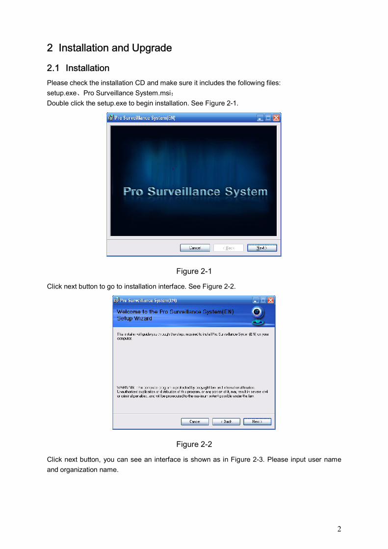
Please check the installation CD and make sure it includes the following files:
setup.exe、Pro Surveillance System.msi;
Double click the setup.exe to begin installation. See Figure 2-1.
Figure 2-1
Click next button to go to installation interface. See Figure 2-2.
Figure 2-2
Click next button, you can see an interface is shown as in Figure 2-3. Please input user name
and organization name.
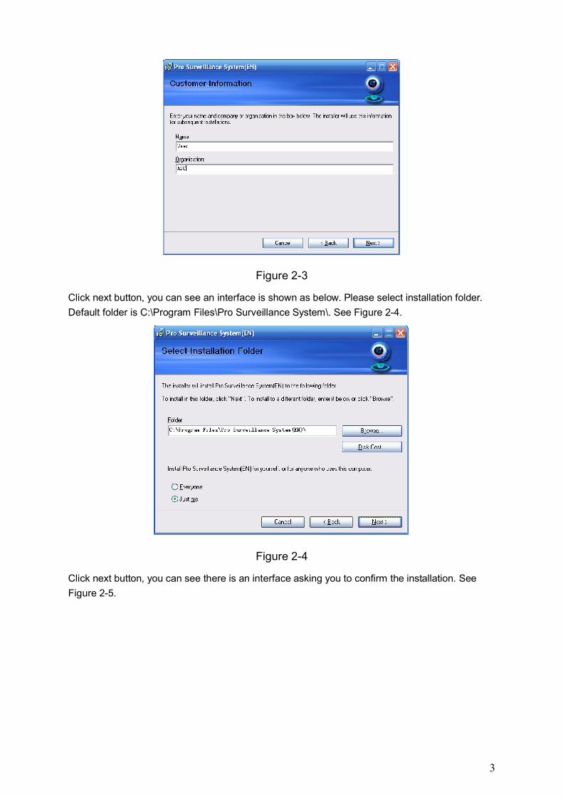
3
Figure 2-3
Click next button, you can see an interface is shown as below. Please select installation folder.
Default folder is C:\Program Files\Pro Surveillance System\. See Figure 2-4.
Figure 2-4
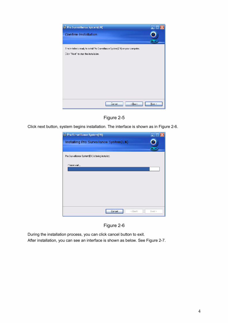
Click next button, you can see there is an interface asking you to confirm the installation. See
Figure 2-5.
4
Figure 2-5
Click next button, system begins installation. The interface is shown as in Figure 2-6.
Figure 2-6
During the installation process, you can click cancel button to exit.
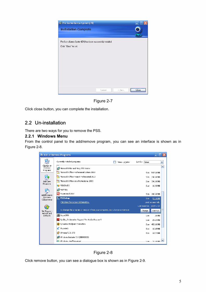
After installation, you can see an interface is shown as below. See Figure 2-7.
5
Figure 2-7
Click close button, you can complete the installation.
2.2 Un-installation
There are two ways for you to remove the PSS.
2.2.1 Windows Menu From the control panel to the add/remove program, you can see an interface is shown as in
Figure 2-8.
Figure 2-8
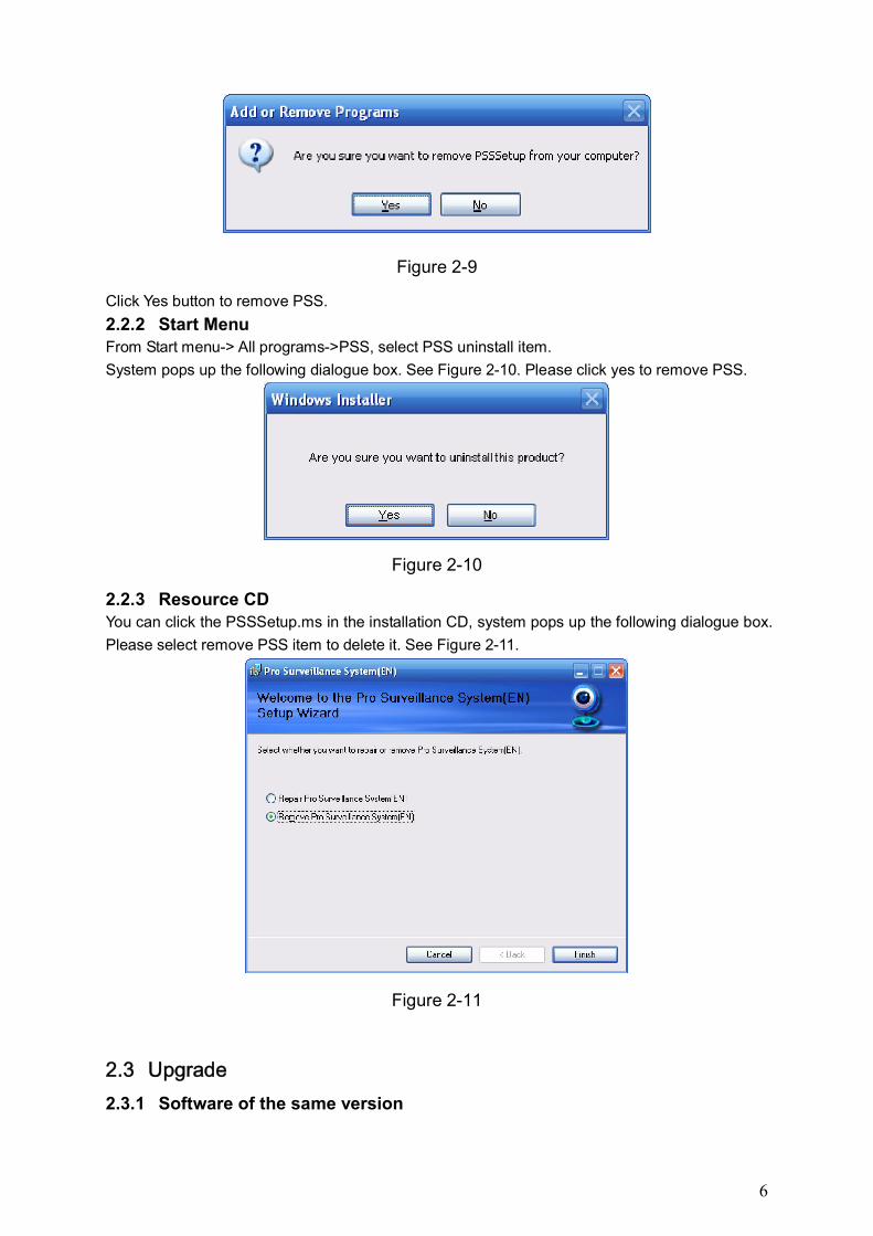
Click remove button, you can see a dialogue box is shown as in Figure 2-9.
6
Figure 2-9
Click Yes button to remove PSS.
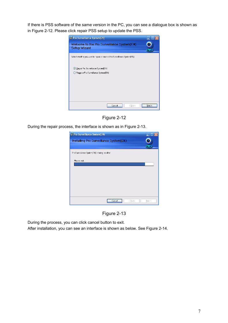
2.2.2 Start Menu From Start menu-> All programs->PSS, select PSS uninstall item.
System pops up the following dialogue box. See Figure 2-10. Please click yes to remove PSS.
Figure 2-10
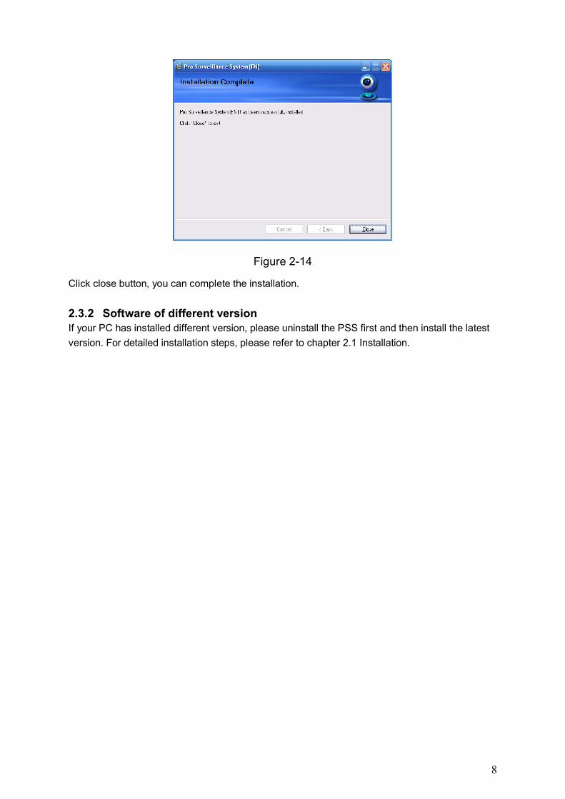
2.2.3 Resource CD You can click the PSSSetup.ms in the installation CD, system pops up the following dialogue box.
Please select remove PSS item to delete it. See Figure 2-11.
Figure 2-11
2.3 Upgrade
2.3.1 Software of the same version
7
If there is PSS software of the same version in the PC, you can see a dialogue box is shown as
in Figure 2-12. Please click repair PSS setup to update the PSS.
Figure 2-12
During the repair process, the interface is shown as in Figure 2-13.
Figure 2-13
During the process, you can click cancel button to exit.
After installation, you can see an interface is shown as below. See Figure 2-14.
8
Figure 2-14
Click close button, you can complete the installation.
2.3.2 Software of different version If your PC has installed different version, please uninstall the PSS first and then install the latest
version. For detailed installation steps, please refer to chapter 2.1 Installation.
9
3 Interface
Double click PSS icon , you can go to the login interface.
3.1 Login Interface
Login interface is shown as in Figure 3-1.
User name: Input the user account
Password: Please input corresponding password to log in.
OK: Click this button, system can verify the account and then enter the software main
interface.
Cancel: Click this button to exit login interface.
Note:
If it is your first time to run the PSS program, default user name is admin and its password is
admin too. Admin is a super administrator and can not be removed. It can add, modify or
delete other user.
For security reason, please modify your password after first log in.
You can memory your password, so that when you can log in the next time, you do not need
to input user name and password. Please note this function is for your convenient only. Do
not enable this function in public PC.
Figure 3-1
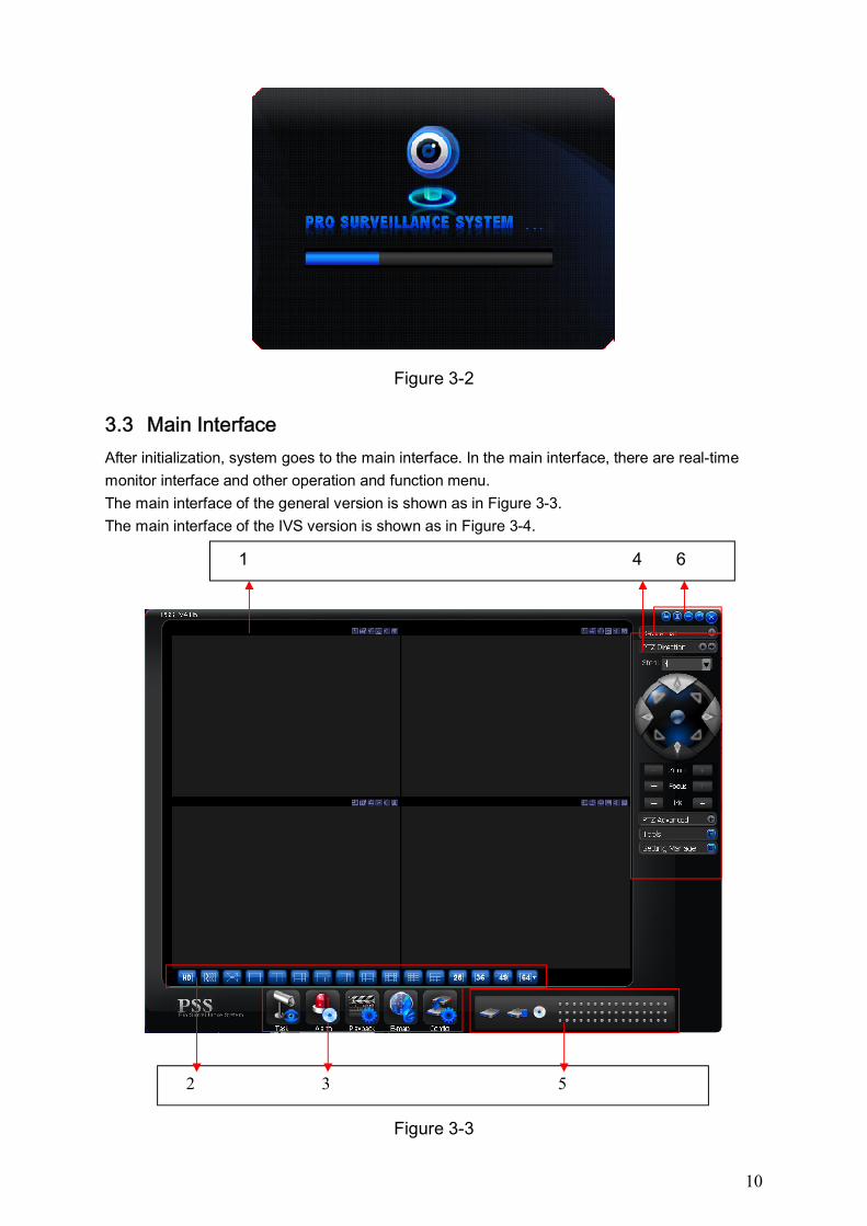
3.2 Initialization Interface
Click OK button, system begins verifying user name and password and then go to the
initialization interface. See Figure 3-2.
Please note it may take a little bit longer to initialize decode card, please be patient.
If it is your first time to use PSS, please go to chapter 3.7.5.2 Option to implement setup.
10
Figure 3-2
3.3 Main Interface
After initialization, system goes to the main interface. In the main interface, there are real-time
monitor interface and other operation and function menu.
The main interface of the general version is shown as in Figure 3-3.
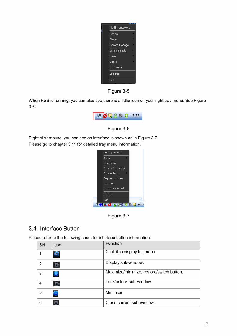
The main interface of the IVS version is shown as in Figure 3-4.
Figure 3-3
1 4 6
2 3 5
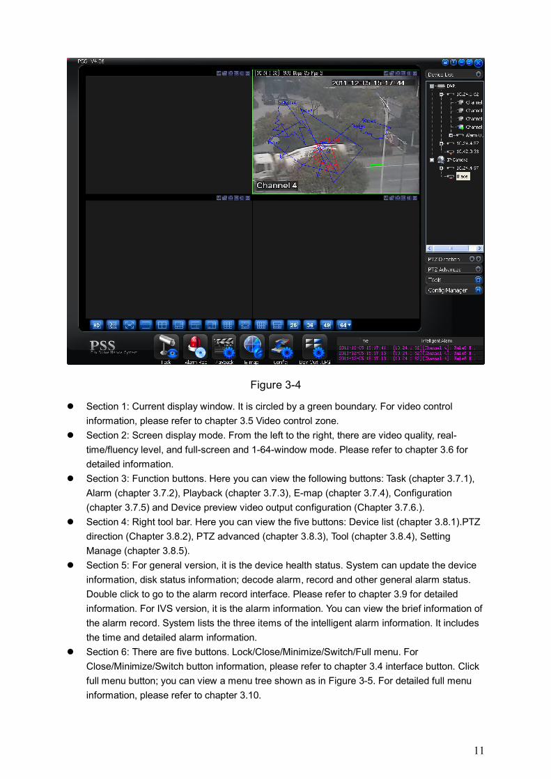
11
Figure 3-4
Section 1: Current display window. It is circled by a green boundary. For video control
information, please refer to chapter 3.5 Video control zone.
Section 2: Screen display mode. From the left to the right, there are video quality, real-
time/fluency level, and full-screen and 1-64-window mode. Please refer to chapter 3.6 for
detailed information.
Section 3: Function buttons. Here you can view the following buttons: Task (chapter 3.7.1),
Alarm (chapter 3.7.2), Playback (chapter 3.7.3), E-map (chapter 3.7.4), Configuration
(chapter 3.7.5) and Device preview video output configuration (Chapter 3.7.6.).
Section 4: Right tool bar. Here you can view the five buttons: Device list (chapter 3.8.1).PTZ
direction (Chapter 3.8.2), PTZ advanced (chapter 3.8.3), Tool (chapter 3.8.4), Setting
Manage (chapter 3.8.5).
Section 5: For general version, it is the device health status. System can update the device
information, disk status information; decode alarm, record and other general alarm status.
Double click to go to the alarm record interface. Please refer to chapter 3.9 for detailed
information. For IVS version, it is the alarm information. You can view the brief information of
the alarm record. System lists the three items of the intelligent alarm information. It includes
the time and detailed alarm information.
Section 6: There are five buttons. Lock/Close/Minimize/Switch/Full menu. For
Close/Minimize/Switch button information, please refer to chapter 3.4 interface button. Click
full menu button; you can view a menu tree shown as in Figure 3-5. For detailed full menu
information, please refer to chapter 3.10.
12
Figure 3-5
When PSS is running, you can also see there is a littlie icon on your right tray menu. See Figure
3-6.
Figure 3-6
Right click mouse, you can see an interface is shown as in Figure 3-7.
Please go to chapter 3.11 for detailed tray menu information.
Figure 3-7
3.4 Interface Button
Please refer to the following sheet for interface button information.
SN Icon Function
1
Click it to display full menu.
2 Display sub-window.
3
Maximize/minimize, restore/switch button.
4 Lock/unlock sub-window.
5
Minimize
6 Close current sub-window.
13
7
Close current window.
8
Tray menu button.
9 Lock Click lock button, you can lock current application to avoid vicious operation. See Figure 3-8. You can see admin has locked current application.
Figure 3-8
Click the unlock button in Figure 3-8, system pops up the following dialogue box. See Figure 3-9. You need to input the proper password to login again.
Figure 3-9
10
These two button are usually in user management or configuration interface.
Click Ok to save current modification and then exit. Click Cancel to exit without saving current setup.
3.5 Video Control Zone
On the video upper right, there are six icons. See Figure 3-10.
Figure 3-10
Please refer to the following sheet for detail information.
1 Digital zoom
Click this button and then left drag the mouse in the zone to zoom in. Right click mouse system restores original status.
2 Change show mode
Resize or switch to full screen mode. You can double click mouse to change the mode.
12 3 4 5 6
14
3 Local record
When you click local record button, the system begins recording. The recorded file is saved to system folder.
4 Capture picture
You can snapshoot important video. All images are memorized in system folder.
5 Audio Turn on or off audio.(It has no relationship with system audio setup )
6 Close video
Close video in current window.
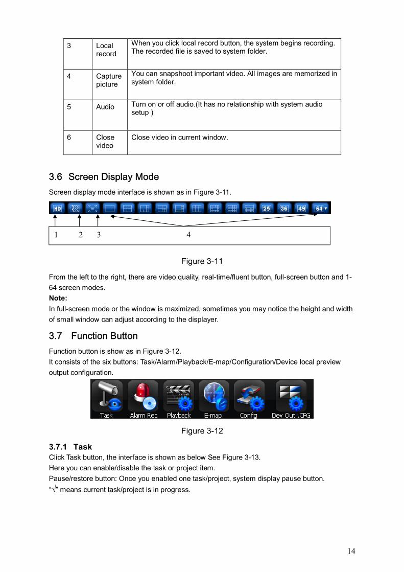
3.6 Screen Display Mode
Screen display mode interface is shown as in Figure 3-11.
Figure 3-11
From the left to the right, there are video quality, real-time/fluent button, full-screen button and 1-
64 screen modes.
Note:
In full-screen mode or the window is maximized, sometimes you may notice the height and width
of small window can adjust according to the displayer.
3.7 Function Button
Function button is show as in Figure 3-12.
It consists of the six buttons: Task/Alarm/Playback/E-map/Configuration/Device local preview
output configuration.
Figure 3-12
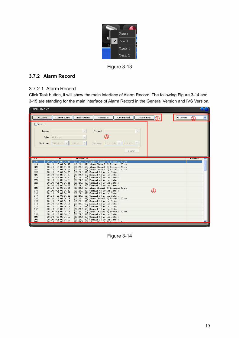
3.7.1 Task Click Task button, the interface is shown as below See Figure 3-13.
Here you can enable/disable the task or project item.
Pause/restore button: Once you enabled one task/project, system display pause button.
“√” means current task/project is in progress.
1 2 3 4
15
Figure 3-13
3.7.2 Alarm Record
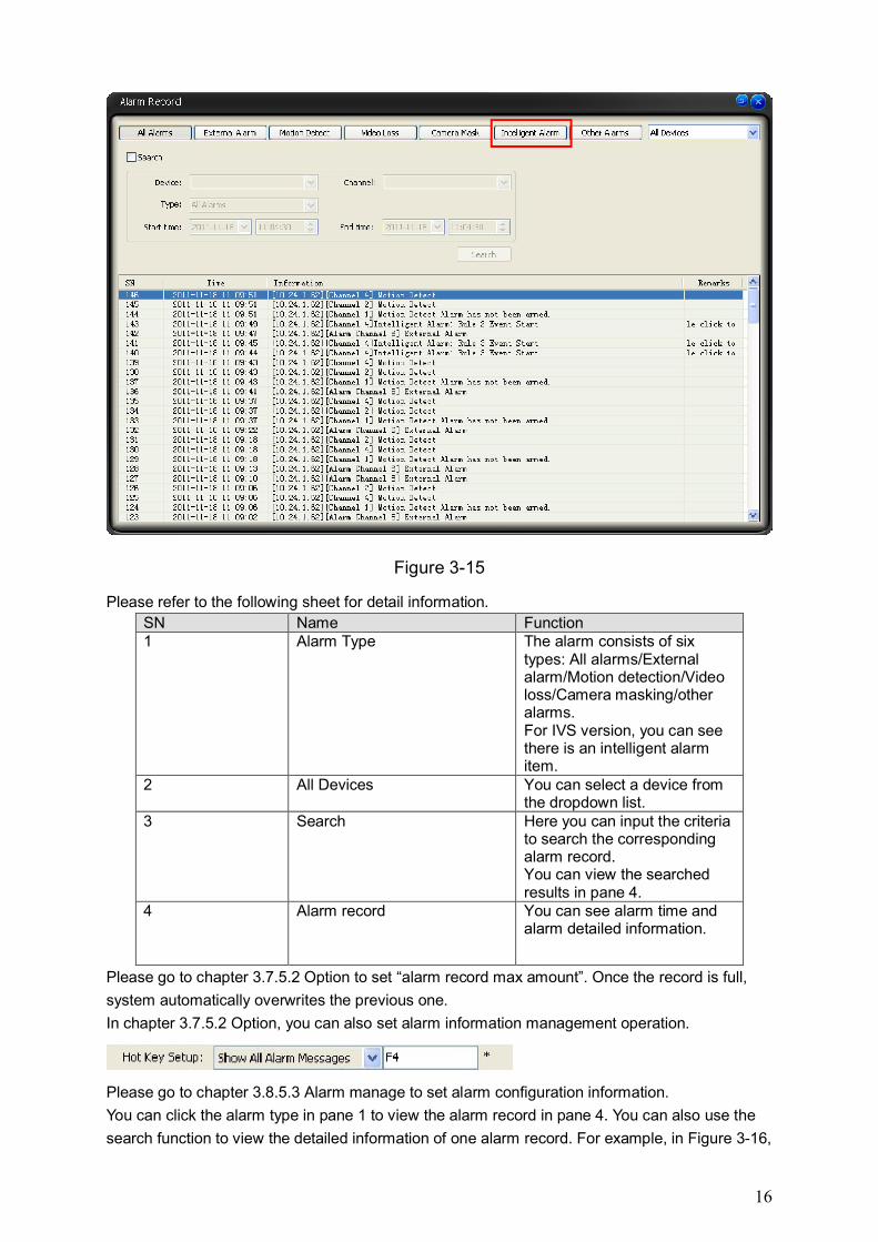
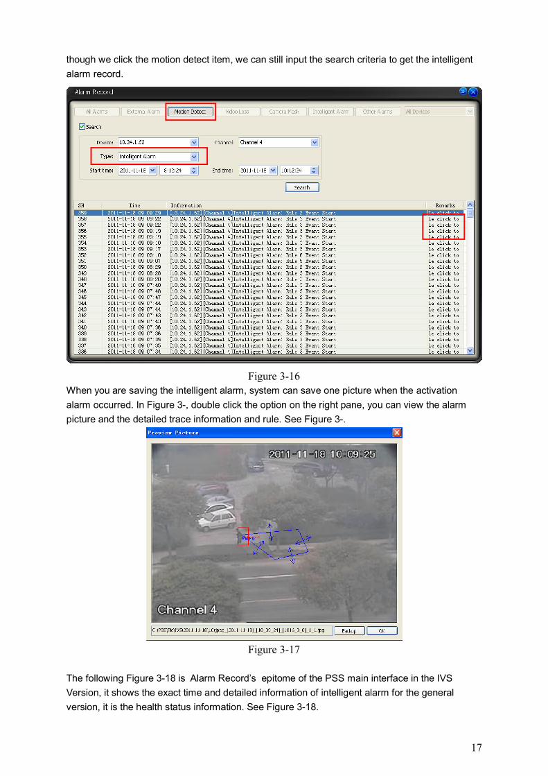
3.7.2.1 Alarm Record Click Task button, it will show the main interface of Alarm Record. The following Figure 3-14 and
3-15 are standing for the main interface of Alarm Record in the General Version and IVS Version.
Figure 3-14
①
③
④
②
16
Figure 3-15
Please refer to the following sheet for detail information.
SN Name Function 1 Alarm Type The alarm consists of six
types: All alarms/External alarm/Motion detection/Video loss/Camera masking/other alarms. For IVS version, you can see there is an intelligent alarm item.
2 All Devices You can select a device from the dropdown list.
3 Search Here you can input the criteria to search the corresponding alarm record. You can view the searched results in pane 4.
4 Alarm record You can see alarm time and alarm detailed information.
Please go to chapter 3.7.5.2 Option to set “alarm record max amount”. Once the record is full,
system automatically overwrites the previous one.
In chapter 3.7.5.2 Option, you can also set alarm information management operation.
Please go to chapter 3.8.5.3 Alarm manage to set alarm configuration information.
You can click the alarm type in pane 1 to view the alarm record in pane 4. You can also use the
search function to view the detailed information of one alarm record. For example, in Figure 3-16,
17
though we click the motion detect item, we can still input the search criteria to get the intelligent
alarm record.
Figure 3-16
When you are saving the intelligent alarm, system can save one picture when the activation
alarm occurred. In Figure 3-, double click the option on the right pane, you can view the alarm
picture and the detailed trace information and rule. See Figure 3-.
Figure 3-17
The following Figure 3-18 is Alarm Record’s epitome of the PSS main interface in the IVS
Version, it shows the exact time and detailed information of intelligent alarm for the general
version, it is the health status information. See Figure 3-18.
18
Figure 3-18
3.7.3 Playback Here you can view the remote device you can control, and corresponding linkage (activation)
record, local record playback and download.
Please note the play control button at the bottom of the interface is for current video window only.
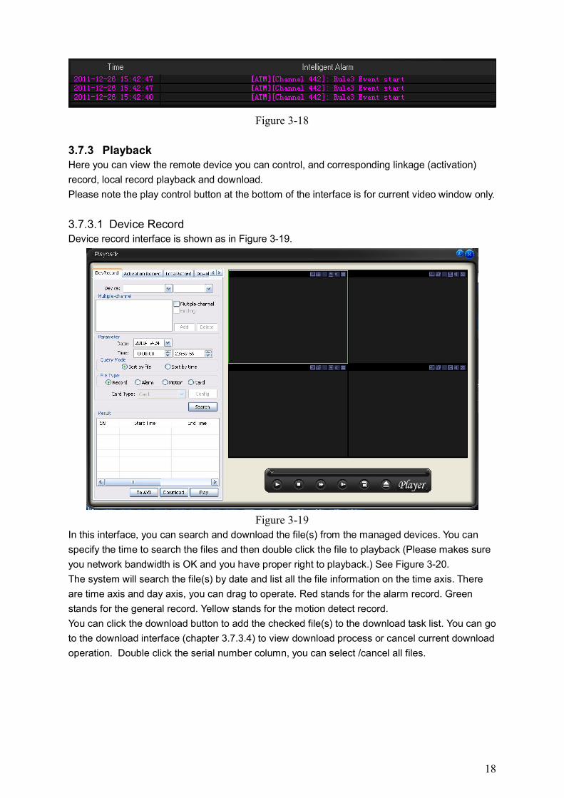
3.7.3.1 Device Record Device record interface is shown as in Figure 3-19.
Figure 3-19
In this interface, you can search and download the file(s) from the managed devices. You can
specify the time to search the files and then double click the file to playback (Please makes sure
you network bandwidth is OK and you have proper right to playback.) See Figure 3-20.
The system will search the file(s) by date and list all the file information on the time axis. There
are time axis and day axis, you can drag to operate. Red stands for the alarm record. Green
stands for the general record. Yellow stands for the motion detect record.
You can click the download button to add the checked file(s) to the download task list. You can go
to the download interface (chapter 3.7.3.4) to view download process or cancel current download
operation. Double click the serial number column, you can select /cancel all files.
19
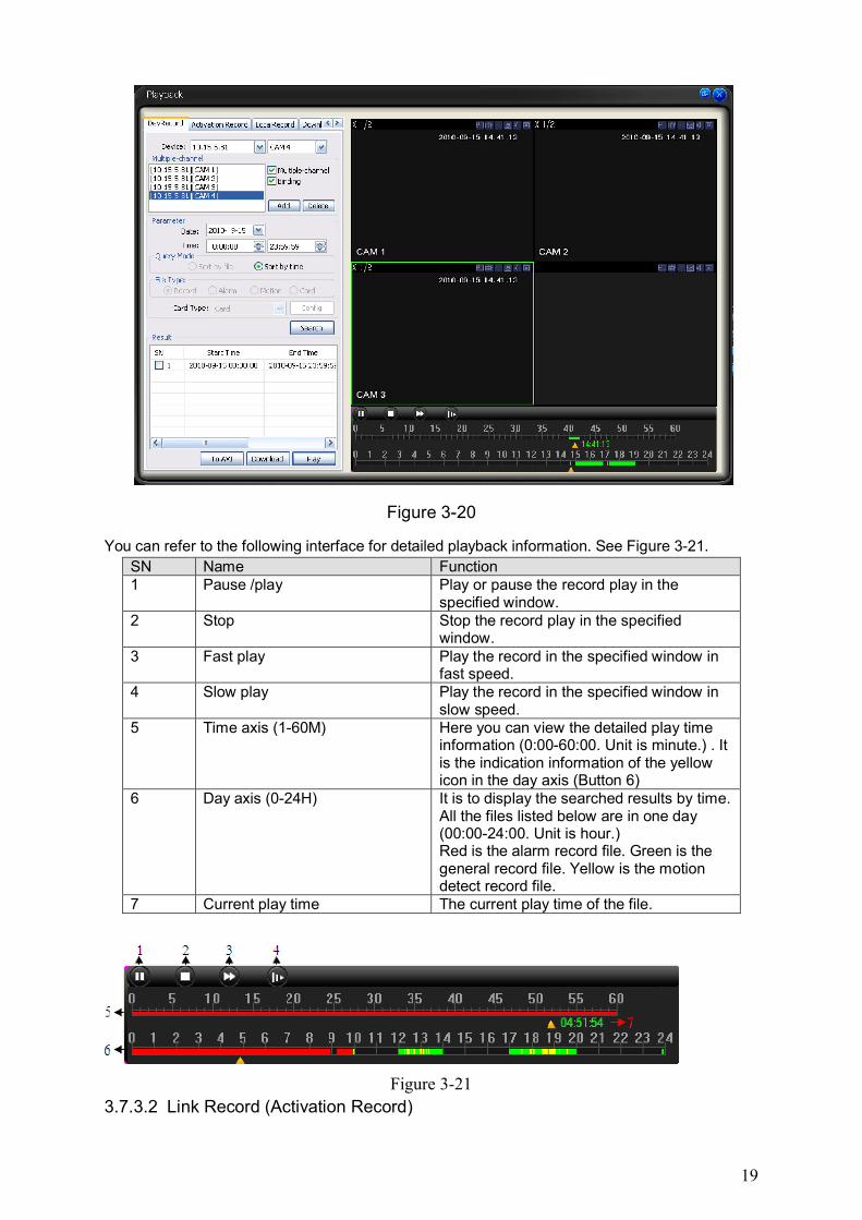
Figure 3-20
You can refer to the following interface for detailed playback information. See Figure 3-21.
SN Name Function 1 Pause /play Play or pause the record play in the
specified window. 2 Stop Stop the record play in the specified
window. 3 Fast play Play the record in the specified window in
fast speed. 4 Slow play Play the record in the specified window in
slow speed. 5 Time axis (1-60M) Here you can view the detailed play time
information (0:00-60:00. Unit is minute.) . It is the indication information of the yellow icon in the day axis (Button 6)
6 Day axis (0-24H) It is to display the searched results by time. All the files listed below are in one day (00:00-24:00. Unit is hour.) Red is the alarm record file. Green is the general record file. Yellow is the motion detect record file.
7 Current play time The current play time of the file.
Figure 3-21
3.7.3.2 Link Record (Activation Record)
20
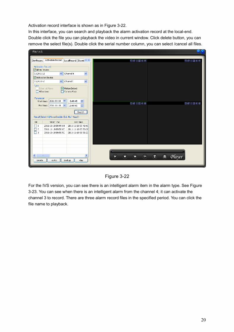
Activation record interface is shown as in Figure 3-22.
In this interface, you can search and playback the alarm activation record at the local-end.
Double click the file you can playback the video in current window. Click delete button, you can
remove the select file(s). Double click the serial number column, you can select /cancel all files.
Figure 3-22
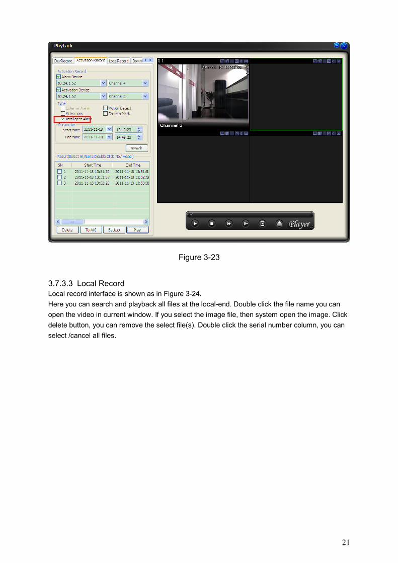
For the IVS version, you can see there is an intelligent alarm item in the alarm type. See Figure
3-23. You can see when there is an intelligent alarm from the channel 4; it can activate the
channel 3 to record. There are three alarm record files in the specified period. You can click the
file name to playback.
21
Figure 3-23
3.7.3.3 Local Record Local record interface is shown as in Figure 3-24.
Here you can search and playback all files at the local-end. Double click the file name you can
open the video in current window. If you select the image file, then system open the image. Click
delete button, you can remove the select file(s). Double click the serial number column, you can
select /cancel all files.
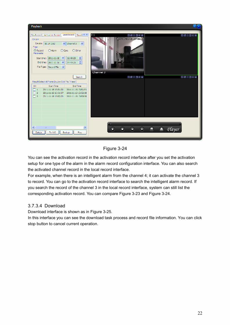
22
Figure 3-24
You can see the activation record in the activation record interface after you set the activation
setup for one type of the alarm in the alarm record configuration interface. You can also search
the activated channel record in the local record interface.
For example, when there is an intelligent alarm from the channel 4; it can activate the channel 3
to record. You can go to the activation record interface to search the intelligent alarm record. If
you search the record of the channel 3 in the local record interface, system can still list the
corresponding activation record. You can compare Figure 3-23 and Figure 3-24.
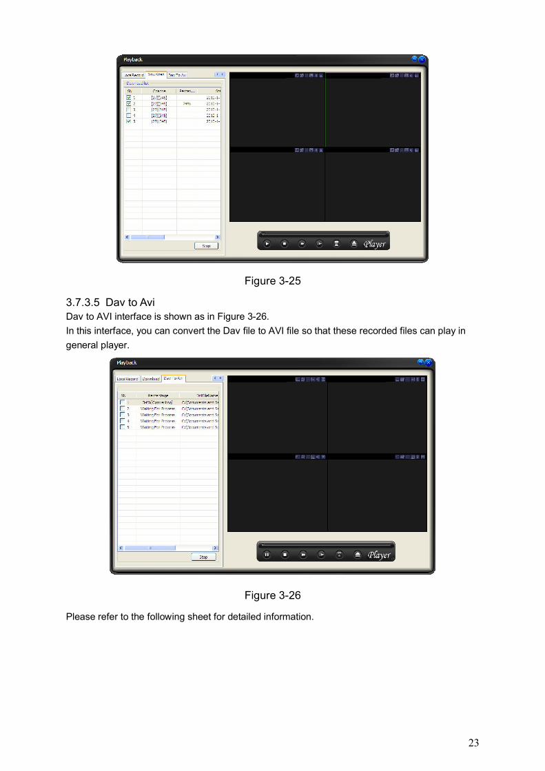
3.7.3.4 Download Download interface is shown as in Figure 3-25.
In this interface you can see the download task process and record file information. You can click
stop button to cancel current operation.
23
Figure 3-25
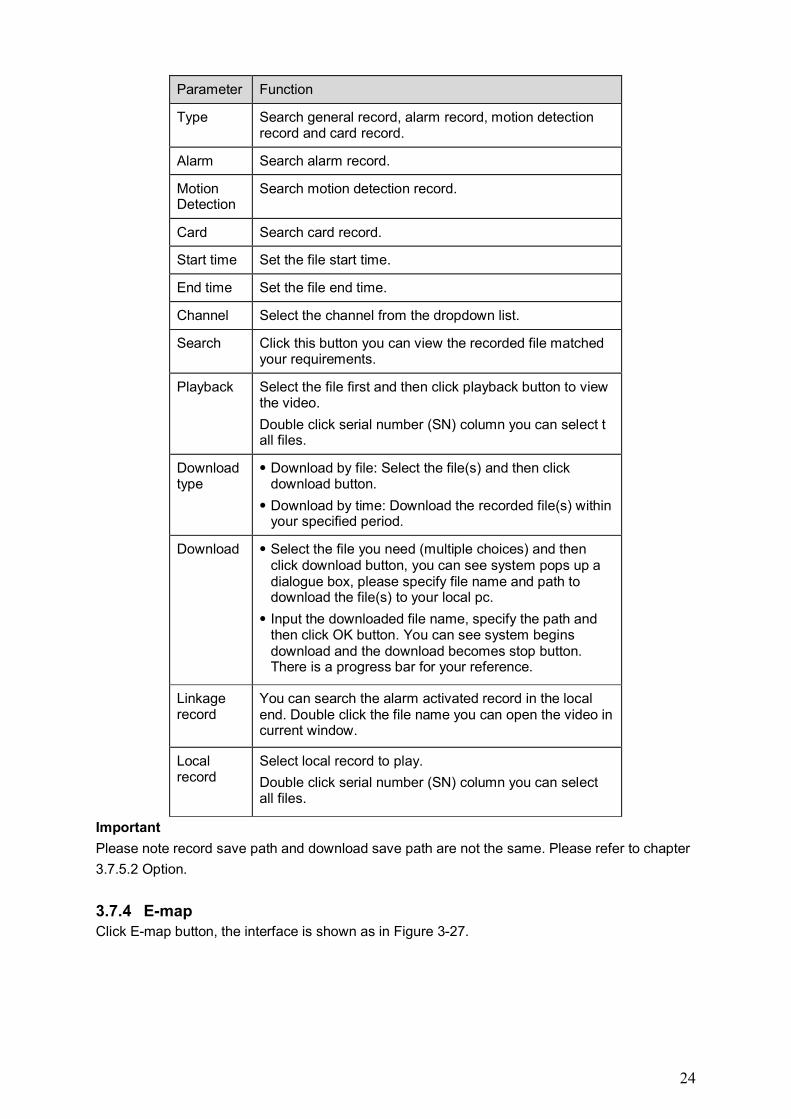
3.7.3.5 Dav to Avi Dav to AVI interface is shown as in Figure 3-26.
In this interface, you can convert the Dav file to AVI file so that these recorded files can play in
general player.
Figure 3-26
Please refer to the following sheet for detailed information.
24
Parameter Function
Type Search general record, alarm record, motion detection record and card record.
Alarm Search alarm record.
Motion Detection
Search motion detection record.
Card Search card record.
Start time Set the file start time.
End time Set the file end time.
Channel Select the channel from the dropdown list.
Search Click this button you can view the recorded file matched your requirements.
Playback Select the file first and then click playback button to view the video.
Double click serial number (SN) column you can select t all files.
Download type
Download by file: Select the file(s) and then click download button.
Download by time: Download the recorded file(s) within your specified period.
Download Select the file you need (multiple choices) and then click download button, you can see system pops up a dialogue box, please specify file name and path to download the file(s) to your local pc.
Input the downloaded file name, specify the path and then click OK button. You can see system begins download and the download becomes stop button. There is a progress bar for your reference.
Linkage record
You can search the alarm activated record in the local end. Double click the file name you can open the video in current window.
Local record
Select local record to play.
Double click serial number (SN) column you can select all files.
Important
Please note record save path and download save path are not the same. Please refer to chapter
3.7.5.2 Option.
3.7.4 E-map Click E-map button, the interface is shown as in Figure 3-27.
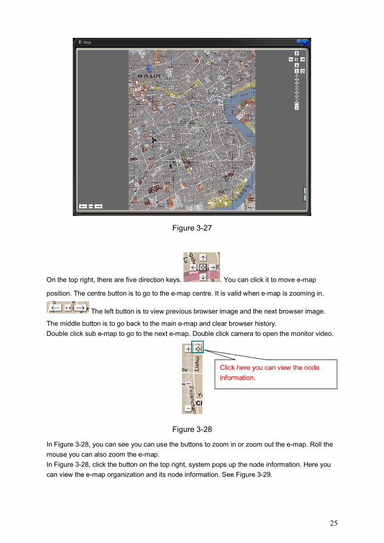
25
Figure 3-27
On the top right, there are five direction keys. . You can click it to move e-map
position. The centre button is to go to the e-map centre. It is valid when e-map is zooming in.
The left button is to view previous browser image and the next browser image.
The middle button is to go back to the main e-map and clear browser history.
Double click sub e-map to go to the next e-map. Double click camera to open the monitor video.
Figure 3-28
In Figure 3-28, you can see you can use the buttons to zoom in or zoom out the e-map. Roll the
mouse you can also zoom the e-map.
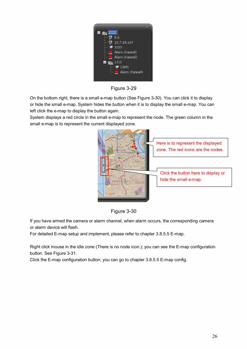
In Figure 3-28, click the button on the top right, system pops up the node information. Here you
can view the e-map organization and its node information. See Figure 3-29.
Click here you can view the node
information.
26
Figure 3-29
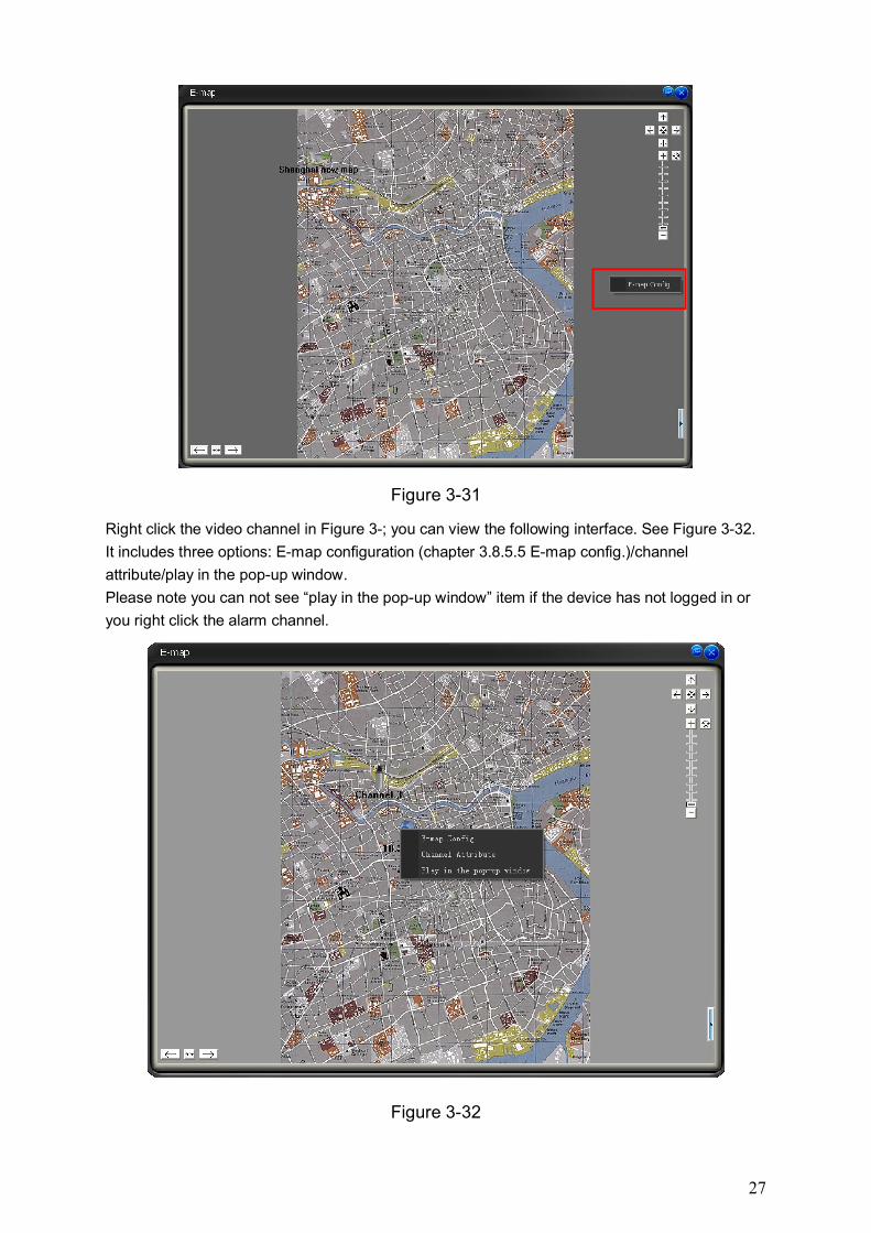
On the bottom right, there is a small e-map button (See Figure 3-30). You can click it to display
or hide the small e-map. System hides the button when it is to display the small e-map. You can
left click the e-map to display the button again.
System displays a red circle in the small e-map to represent the node. The green column in the
small e-map is to represent the current displayed zone.
Figure 3-30
If you have armed the camera or alarm channel, when alarm occurs, the corresponding camera
or alarm device will flash.
For detailed E-map setup and implement, please refer to chapter 3.8.5.5 E-map.
Right click mouse in the idle zone (There is no node icon.); you can see the E-map configuration
button. See Figure 3-31.
Click the E-map configuration button; you can go to chapter 3.8.5.5 E-map config.
Click the button here to display or
hide the small e-map.
Here is to represent the displayed
zone. The red icons are the nodes.
27
Figure 3-31
Right click the video channel in Figure 3-; you can view the following interface. See Figure 3-32.
It includes three options: E-map configuration (chapter 3.8.5.5 E-map config.)/channel
attribute/play in the pop-up window.
Please note you can not see “play in the pop-up window” item if the device has not logged in or
you right click the alarm channel.
Figure 3-32
28
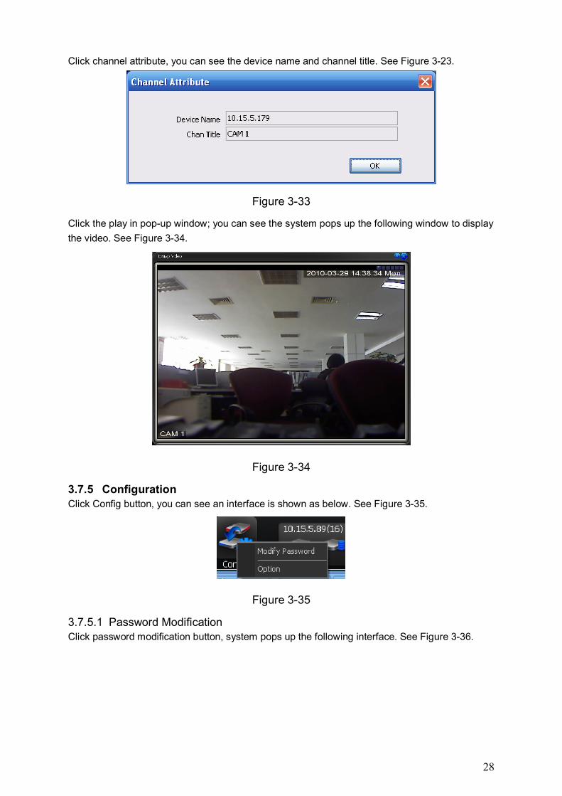
Click channel attribute, you can see the device name and channel title. See Figure 3-23.
Figure 3-33
Click the play in pop-up window; you can see the system pops up the following window to display
the video. See Figure 3-34.
Figure 3-34
3.7.5 Configuration Click Config button, you can see an interface is shown as below. See Figure 3-35.
Figure 3-35
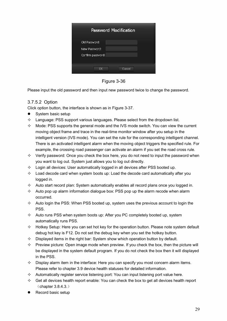
3.7.5.1 Password Modification Click password modification button, system pops up the following interface. See Figure 3-36.
29
Figure 3-36
Please input the old password and then input new password twice to change the password.
3.7.5.2 Option Click option button, the interface is shown as in Figure 3-37.
System basic setup
Language: PSS support various languages. Please select from the dropdown list.
Mode: PSS supports the general mode and the IVS mode switch. You can view the current
moving object frame and trace in the real-time monitor window after you setup in the
intelligent version (IVS mode). You can set the rule for the corresponding intelligent channel.
There is an activated intelligent alarm when the moving object triggers the specified rule. For
example, the crossing road passenger can activate an alarm if you set the road cross rule.
Verify password: Once you check the box here, you do not need to input the password when
you want to log out. System just allows you to log out directly.
Login all devices: User automatically logged in all devices after PSS booted up.
Load decode card when system boots up: Load the decode card automatically after you
logged in.
Auto start record plan: System automatically enables all record plans once you logged in.
Auto pop up alarm information dialogue box: PSS pop up the alarm recode when alarm
occurred.
Auto login the PSS: When PSS booted up, system uses the previous account to login the
PSS.
Auto runs PSS when system boots up: After you PC completely booted up, system
automatically runs PSS.
Hotkey Setup: Here you can set hot key for the operation button. Please note system default
debug hot key is F12. Do not set the debug key when you set the hotkey button.
Displayed items in the right bar: System show which operation button by default.
Preview picture: Open image mode when preview. If you check the box, then the picture will
be displayed in the system default program. If you do not check the box then it will displayed
in the PSS.
Display alarm item in the interface: Here you can specify you most concern alarm items.
Please refer to chapter 3.9 device health statuses for detailed information.
Automatically register service listening port: You can input listening port value here.
Get all devices health report enable: You can check the box to get all devices health report
(chapter 3.8.4.3.)
Record basic setup
30
Snapshot picture path: You can specify image save default path.
Device free minimum space (MB): Once system reaches the threshold, system will overwrite
the old files automatically.
Picture file name rule: You can specify image name rule in the dialogue box.
Record Time (M): Please select from the dropdown list.
Recorded file path: You can specify the file save path.
Recorded file name rule: You can specify file name rule in the dialogue box.
Downloaded file path: You can specify the download file
Auto start monitor setup
Auto start project: The project to be run.
Project name: please input the project you wan to run automatically.
Auto start task: The task to be run.
Task name: Please input the task you wan to run automatically.
Last run: The previous task and project will become active after you successfully logged in
the PSS.
Save last monitor status: System will restore the previous monitor status when it boots up
the next time.
Synchronization time setup
Auto synchronizes the PC time to the device: System automatically synchronizes the time of
the front-end device.
Sync time: You can set the time for the synchronization function operation. (Please make
sure you have enabled synchronization function.)
Auto restart device: Once the local PC time is earlier than the front-end device time, after the
synchronization, front-end device needs to reboot to get the new time activated.
Alarm record basic setup
Alarm record max amount: The max record amount in the alarm record window. System
automatically overwrites the earliest record once the record is full.
Refresh interval: Here you can specify device health status update interval. Please refer to
Chapter 3.9 device health status.
Use pop-up window for alarm activation video: Once you check the box, system will pop up
a new window to display the alarm activation video (not in the main interface). Please refer
to chapter 3.8.4.5 alarm activation video for detail information.
Alarm video window amount: You can specify the window amount for the pop-pup alarm
activation video window. Please refer to chapter 3.8.4.5 alarm activation video for detailed
information.
Add disarming alarm message to the alarm record: Enable this function, system can add the
disarming alarm message to the alarm record interface. Otherwise, system only displays the
armed alarm message.
Alarm information output port: After you checked the box here, all the alarm information from
the devices will be communicated with the peripheral applications via the port you set here.
31
Figure 3-37
Note:
You need to reboot the system to activate the items with *!
Click OK button, you can see a dialogue box shown as in Figure 3-38.
Click Ok to reboot the PSS.
Figure 3-38
3.7.6 Device Preview Output Config The preview output setup function of the PSS is for the DVR device only.
After you set the corresponding output mode of the device, you can click the OK button to
preview according to your setup. This function mainly supports search, set and execute the DVR
local output and the matrix setup plan.
32
Click button in the PSS main interface, you can see the following interface. See
Figure 3-30.
Figure 3-39
SN Name Function 1 DVR list You can view the DVR available. Here we can view
and preview the local output setup of the device. (Please note all the listed devices are DVR only. For other devices such as IPC does not have this function. )
2 Output mode Here you can view the output mode option. It includes: SPOT output and VGA/HDMI/BNC output mode. You can select from these two modes and simulate the display.
3
Preview interface Here we can simulate all the setup plans we just specified in this interface. Enable tour: System can play according to your
setup plan in the pane 3: The enable tour button is null when you open the local output setup interface. It directly displays according to the previous local preview setup. The enable tour button is valid after you clicked the disable tour button.
Disable tour: Click it to turn off current tour interface and the "enable tour" button becomes
③
②
①
33
valid. Click the "enable tour" button again, system begins to display in the pane 3 again.
When you switch from the SPOT mode to the VGA/HDMI/BNC output mode, system automatically disable current SPOT plan and begin the plan of the VGA/HDMI/BNC.
Output Configuration
Click it you can view the detailed setup information. See Figure 3-40.
Select port: There are also two modes: SPOT output and the VGA/HDMI/BNC output. The
setup here is for the following tour setup plan. Once you select VGA/HDMI/BNC output, the
following tour setup and video mode is for VGA/HDMI/BNC output mode only. Your setup in
pane 2 of Figure 3-39 is for preview play mode only.
Tour enable: After you enabled the tour function, you can select various modes to begin the
tour. There is only one status available if you have not enabled the tour function, other
operations are all null.
Window-mode configuration: In pane 3 of Figure 3-39, you can view the local output effect. It
supports 1/4/9/16-window mode. You can select in the following interface.
Resume default: Current setup can become the default mode after you clicked this button.
Figure 3-40
Click OK button in Figure 3-, you can see the following dialogue box. See Figure 3-41. Click OK
button, system will exit current interface (Figure 3-40) and simulate current display mode in the
pane 3 of Figure 3-39. It will also save current setup as the default mode.
Figure 3-41
34
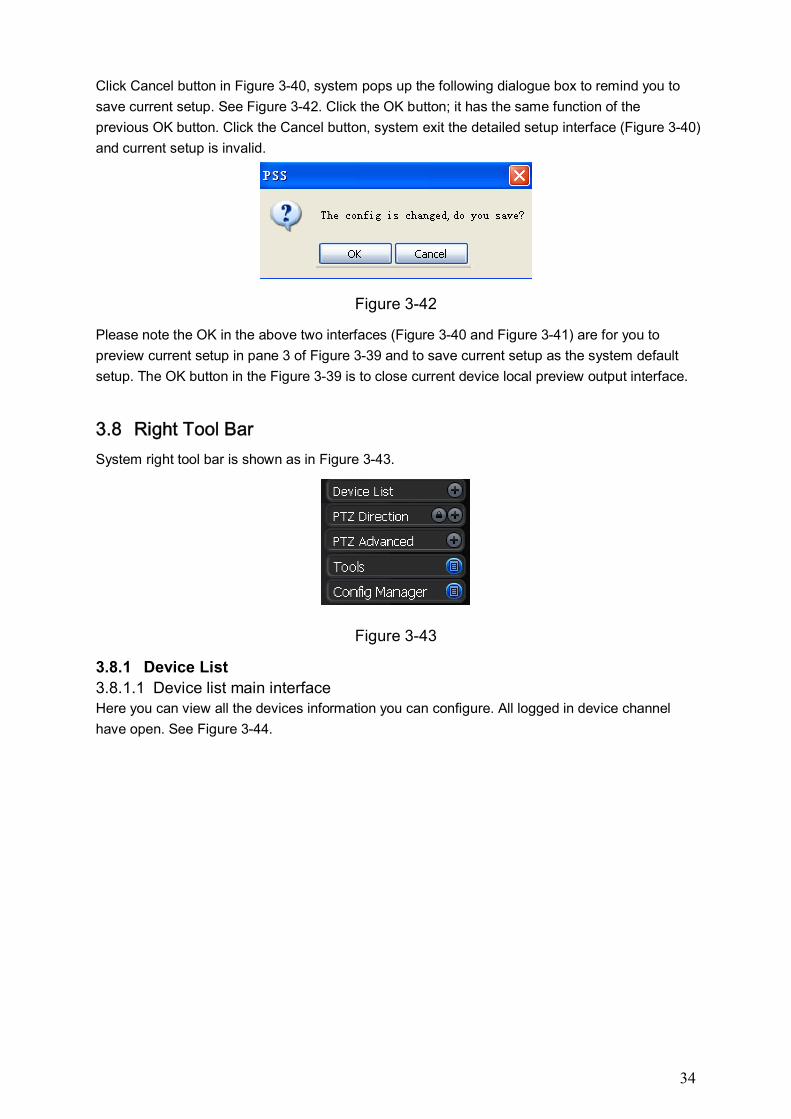
Click Cancel button in Figure 3-40, system pops up the following dialogue box to remind you to
save current setup. See Figure 3-42. Click the OK button; it has the same function of the
previous OK button. Click the Cancel button, system exit the detailed setup interface (Figure 3-40)
and current setup is invalid.
Figure 3-42
Please note the OK in the above two interfaces (Figure 3-40 and Figure 3-41) are for you to
preview current setup in pane 3 of Figure 3-39 and to save current setup as the system default
setup. The OK button in the Figure 3-39 is to close current device local preview output interface.
3.8 Right Tool Bar
System right tool bar is shown as in Figure 3-43.
Figure 3-43
3.8.1 Device List
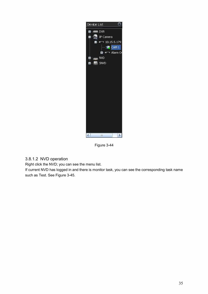
3.8.1.1 Device list main interface Here you can view all the devices information you can configure. All logged in device channel
have open. See Figure 3-44.
35
Figure 3-44
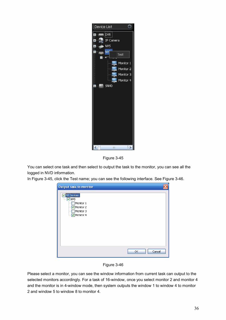
3.8.1.2 NVD operation Right click the NVD; you can see the menu list.
If current NVD has logged in and there is monitor task, you can see the corresponding task name
such as Test. See Figure 3-45.
36
Figure 3-45
You can select one task and then select to output the task to the monitor, you can see all the
logged in NVD information.
In Figure 3-45, click the Test name; you can see the following interface. See Figure 3-46.
Figure 3-46
Please select a monitor, you can see the window information from current task can output to the
selected monitors accordingly. For a task of 16-window, once you select monitor 2 and monitor 4
and the monitor is in 4-window mode, then system outputs the window 1 to window 4 to monitor
2 and window 5 to window 8 to monitor 4.
37
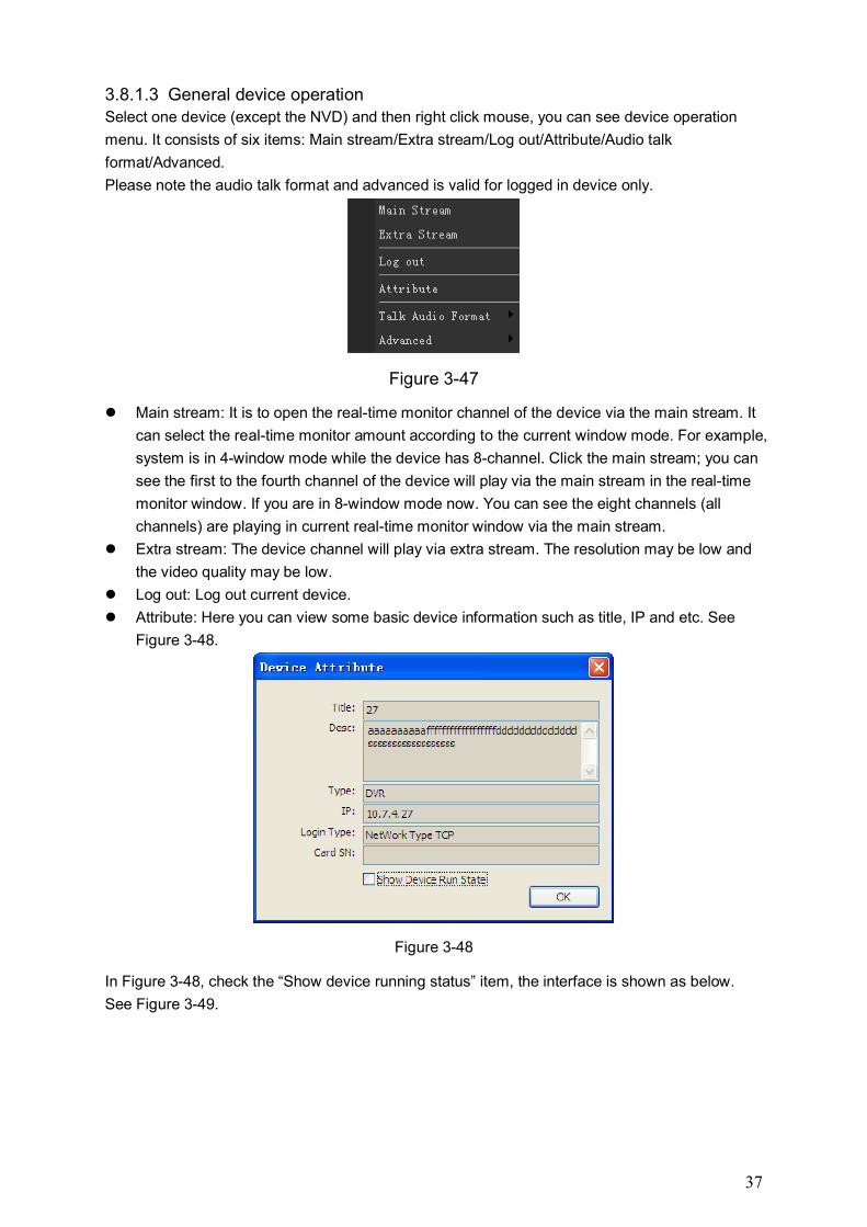
3.8.1.3 General device operation Select one device (except the NVD) and then right click mouse, you can see device operation
menu. It consists of six items: Main stream/Extra stream/Log out/Attribute/Audio talk
format/Advanced.
Please note the audio talk format and advanced is valid for logged in device only.
Figure 3-47
Main stream: It is to open the real-time monitor channel of the device via the main stream. It
can select the real-time monitor amount according to the current window mode. For example,
system is in 4-window mode while the device has 8-channel. Click the main stream; you can
see the first to the fourth channel of the device will play via the main stream in the real-time
monitor window. If you are in 8-window mode now. You can see the eight channels (all
channels) are playing in current real-time monitor window via the main stream.
Extra stream: The device channel will play via extra stream. The resolution may be low and
the video quality may be low.
Log out: Log out current device.
Attribute: Here you can view some basic device information such as title, IP and etc. See
Figure 3-48.
Figure 3-48
In Figure 3-48, check the “Show device running status” item, the interface is shown as below.
See Figure 3-49.
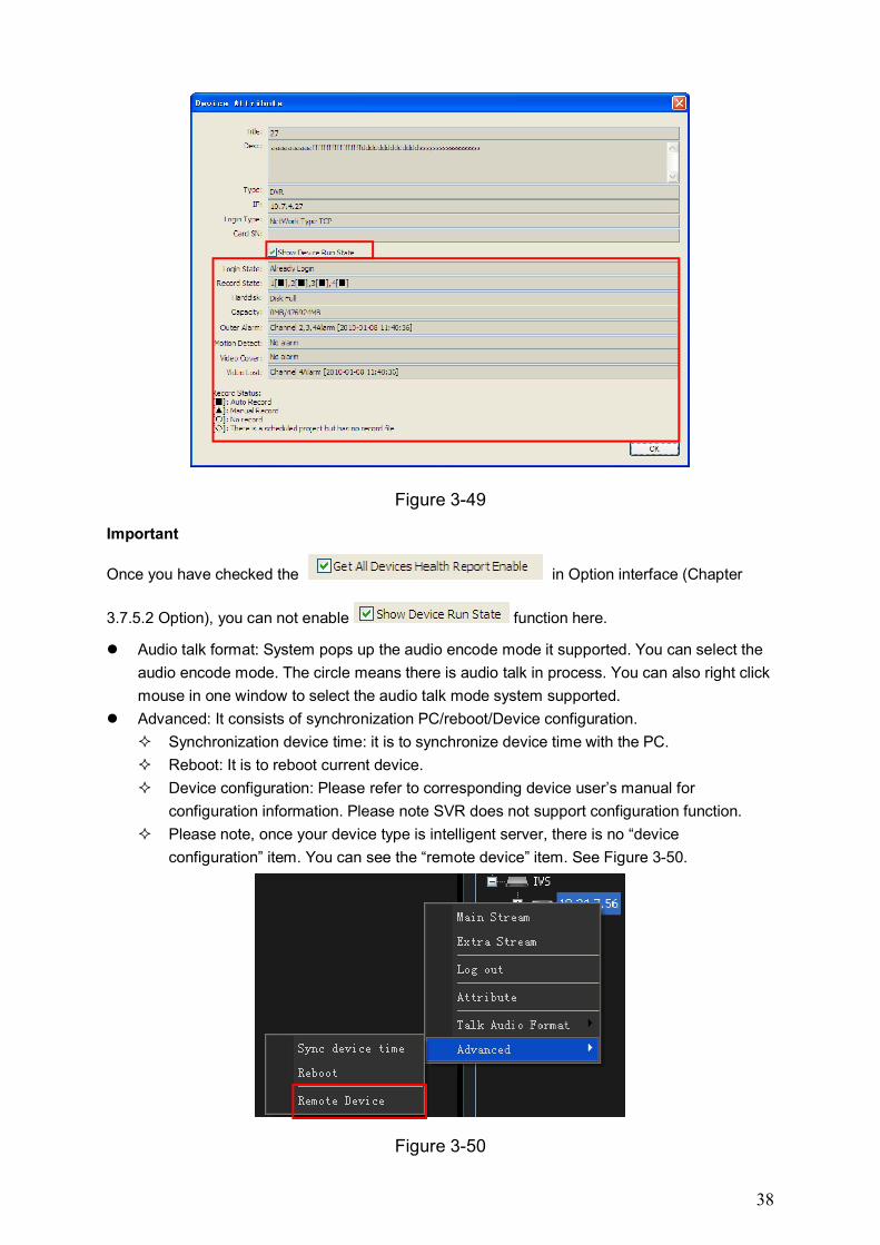
38
Figure 3-49
Important
Once you have checked the in Option interface (Chapter
3.7.5.2 Option), you can not enable function here.
Audio talk format: System pops up the audio encode mode it supported. You can select the
audio encode mode. The circle means there is audio talk in process. You can also right click
mouse in one window to select the audio talk mode system supported.
Advanced: It consists of synchronization PC/reboot/Device configuration.
Synchronization device time: it is to synchronize device time with the PC.
Reboot: It is to reboot current device.
Device configuration: Please refer to corresponding device user’s manual for
configuration information. Please note SVR does not support configuration function.
Please note, once your device type is intelligent server, there is no “device
configuration” item. You can see the “remote device” item. See Figure 3-50.
Figure 3-50
39
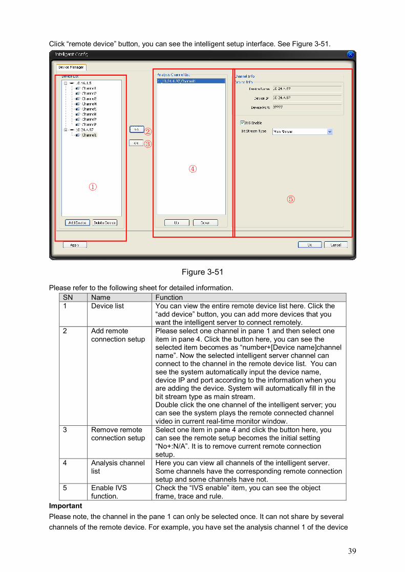
Click “remote device” button, you can see the intelligent setup interface. See Figure 3-51.
Figure 3-51
Please refer to the following sheet for detailed information.
SN Name Function 1 Device list You can view the entire remote device list here. Click the
“add device” button, you can add more devices that you want the intelligent server to connect remotely.
2 Add remote connection setup
Please select one channel in pane 1 and then select one item in pane 4. Click the button here, you can see the selected item becomes as “number+[Device name]channel name”. Now the selected intelligent server channel can connect to the channel in the remote device list. You can see the system automatically input the device name, device IP and port according to the information when you are adding the device. System will automatically fill in the bit stream type as main stream. Double click the one channel of the intelligent server; you can see the system plays the remote connected channel video in current real-time monitor window.
3 Remove remote connection setup
Select one item in pane 4 and click the button here, you can see the remote setup becomes the initial setting “No+:N/A”. It is to remove current remote connection setup.
4 Analysis channel list
Here you can view all channels of the intelligent server. Some channels have the corresponding remote connection setup and some channels have not.
5 Enable IVS function.
Check the “IVS enable” item, you can see the object frame, trace and rule.
Important
Please note, the channel in the pane 1 can only be selected once. It can not share by several
channels of the remote device. For example, you have set the analysis channel 1 of the device
②
③
①
⑤
④
40
10.24.1.62 in pane 4. If you still select the channel 1 of the device 10.24.1.62 in pane 1 and then
select channel 5 in pane 5 and then click the button in pane 2, you can see it is null.
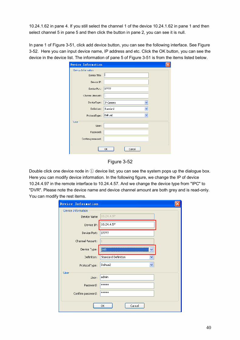
In pane 1 of Figure 3-51, click add device button, you can see the following interface. See Figure
3-52. Here you can input device name, IP address and etc. Click the OK button, you can see the
device in the device list. The information of pane 5 of Figure 3-51 is from the items listed below.
Figure 3-52
Double click one device node in device list; you can see the system pops up the dialogue box. ①
Here you can modify device information. In the following figure, we change the IP of device
10.24.4.97 in the remote interface to 10.24.4.57. And we change the device type from "IPC" to
"DVR". Please note the device name and device channel amount are both grey and is read-only.
You can modify the rest items.
41
Click “Delete device” button, system will remove the selected device from the list. System will
delete the device even you just select one channel of the device. The corresponding channel in
the pane 4 of Figure 3-51 will display as N/A.
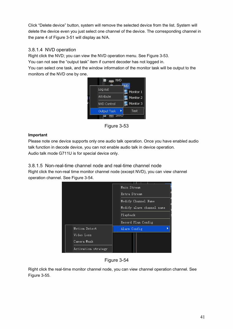
3.8.1.4 NVD operation Right click the NVD; you can view the NVD operation menu. See Figure 3-53.
You can not see the “output task” item if current decoder has not logged in.
You can select one task, and the window information of the monitor task will be output to the
monitors of the NVD one by one.
Figure 3-53
Important
Please note one device supports only one audio talk operation. Once you have enabled audio
talk function in decode device, you can not enable audio talk in device operation.
Audio talk mode G711U is for special device only.
3.8.1.5 Non-real-time channel node and real-time channel node Right click the non-real time monitor channel node (except NVD), you can view channel
operation channel. See Figure 3-54.
Figure 3-54
Right click the real-time monitor channel node, you can view channel operation channel. See
Figure 3-55.
42
Figure 3-55
SN Name Function 1 Main stream It is the bit stream of the playback. The main stream has
the higher resolution than the extra stream. 2 Extra stream 3 Close all video Comparing with the non-real time channel node, you can
see there is a new item “close all video”. See Figure 3-54 and Figure 3-55. It is to close the real-time monitor window that is playing the video from current right click channel. For example, the real-time monitor window 1 and window 3 are playing the video from channel 4. Once you right click the channel 4 and click to close all video. You can see video of window 1 and window 3 are both closed. For the IVS version, the right click menu difference between the real-time channel and the non-real time is the “close all video” item too.
4 Modify channel name Click it; you can see system pops up a dialogue box for you to input the old password and the new channel name. Click the OK button, you can modify the channel name.
5 Modify alarm channel name
Click it, you can see the system pops up the alarm channel name dialogue box.
6 Record playback Here you can view the local record, activation record and device record of the current channel. Please refer to chapter 3.7.3 playback for detailed information. Please note, when you go to the record playback interface from the selection item here, you can see the channel of the local record and device record are both read-only and can not modify. For the alarm device and activation device of the activation record are set to as current channel too. But you can click the check box to modify channel setup. If you go to the record playback interface from the tool bar, you can select the channel of the local record, activation record and the device record.
7 Record task config It is to set the record task of one channel. Click the start task button after you completed the setup, you can see system begin auto record in the specified period. Please refer to chapter 3.8.5.2 for detailed information.
8 Alarm config It is to arm the alarm type of current channel. For IVS version, you can see the intelligent setup. You can set the rule of the channel. And there is an intelligent
43
alarm type in the alarm setup interface. Here you can set the rule of the channel. You can see the intelligent alarm type in the alarm setup. See Figure 3-56.
Figure 3-56
Click the “Intelligent Config “item in Figure 3-56, you can see the following interface. See Figure
3-57.
Figure 3-57
Global Configuration
Here you can view current channel number you select for the intelligent analysis. Right now the
scene type only supports ATM. In the initialization mode, “Delete area” button is null. Click “Add
area” button, system adds the default area name as Area 1. In pane 1 of Figure 3-57, you can
draw to specify the area. Please left click the mouse and then drag to draw the line. Please
release the button if you want to turn an angle. If you still want to change the direction, you can
②
①
44
left click the mouse again. Please right click the mouse to complete the draw. Now you can get a
polygon. “Add gauge” is to add the tilt gauge and the vertical gauge to the zone. Please input the
actual size and then click the “Add gauge” button, now the drawing gauge is the value you input.
There are only three tilt gauges and one pan gauge in one zone. The withdraw time up is for
AMT scene only.
Module Configuration
Module configuration interface is shown as in Figure 3-58.
Current channel number: It is to display current analysis setup channel.
Module list: The module here is matching the object type. Each module is corresponding to
one object type. You can implement the module operation via the "Add module" and the
"Delete module" interface. Please note the module shall be unique.
Video zone: It is to display the real-time video of current channel. You can draw directly in
this zone to set detect zone, excluded zone and etc.
Module information:
Snap enable: Check the box to enable snap function when an alarm occurred.
Detect zone: Each module has its unique detect zone. There may no detect zone when
system is initializing. You can use the "Add detect zone" button to add. The "Add detect
zone" button is null after you successfully added a zone. (Important: The detect zone can
only be redraw and can not be removed after successfully added.)
Excluded zone: You can add the excluded zone in the detect zone after you selected the
detect zone node. The excluded zone can not exceed the detect zone. It can redraw and
can also be removed.
Object type: It is the detected object type the device supported. The object type is defined by
the device. (Important: One module is matching one object type.)
Sensitivity: It is to set detect sensitivity. The higher the sensitivity is, the easier the object is
to be detected.
Object filter: You need to check the enable box to enable the object filter function. After you
enabled the object filter function, you can set the object min and max size. Please note this
object filter is for the moving object size, no matter it is in the object zones. In the object filter
interface, the green boundary is the max value and the min boundary is the min value. See
Figure 3-59. For the object smaller than the min value or the object higher than the max
value, it will be filtered. That is to say, there is no activation alarm even it triggers the rule.
45
Figure 3-58
Figure 3-59
Rule Configuration
The rule configuration is shown as in Figure 3-60.
Current channel No.: It is to display current analysis channel.
Rule list: It is the added rule information list; you can click the node to view the
corresponding rule information. You can check the box to enable the corresponding rule.
The default rule name is rule+No. Please note you need to check the rule name here so that
you can view it in the real-time monitor window.
Redraw: It is to draw current rule again.
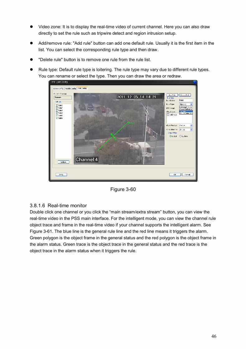
46
Video zone: It is to display the real-time video of current channel. Here you can also draw
directly to set the rule such as tripwire detect and region intrusion setup.
Add/remove rule: "Add rule" button can add one default rule. Usually it is the first item in the
list. You can select the corresponding rule type and then draw.
"Delete rule" button is to remove one rule from the rule list.
Rule type: Default rule type is loitering. The rule type may vary due to different rule types.
You can rename or select the type. Then you can draw the area or redraw.
Figure 3-60
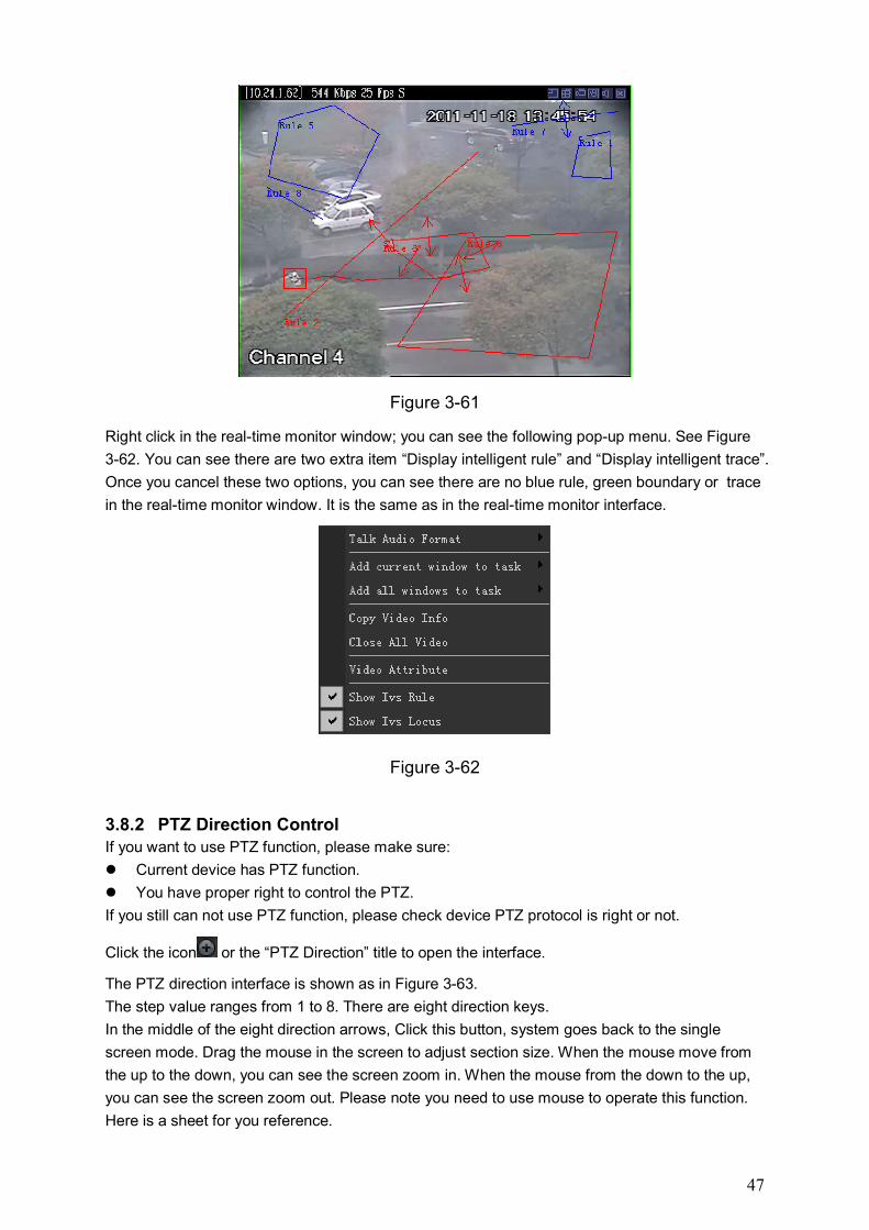
3.8.1.6 Real-time monitor Double click one channel or you click the “main stream/extra stream” button, you can view the
real-time video in the PSS main interface. For the intelligent mode, you can view the channel rule
object trace and frame in the real-time video if your channel supports the intelligent alarm. See
Figure 3-61. The blue line is the general rule line and the red line means it triggers the alarm.
Green polygon is the object frame in the general status and the red polygon is the object frame in
the alarm status. Green trace is the object trace in the general status and the red trace is the
object trace in the alarm status when it triggers the rule.
47
Figure 3-61
Right click in the real-time monitor window; you can see the following pop-up menu. See Figure
3-62. You can see there are two extra item “Display intelligent rule” and “Display intelligent trace”.
Once you cancel these two options, you can see there are no blue rule, green boundary or trace
in the real-time monitor window. It is the same as in the real-time monitor interface.
Figure 3-62
3.8.2 PTZ Direction Control If you want to use PTZ function, please make sure:
Current device has PTZ function.
You have proper right to control the PTZ.
If you still can not use PTZ function, please check device PTZ protocol is right or not.
Click the icon or the “PTZ Direction” title to open the interface.
The PTZ direction interface is shown as in Figure 3-63.
The step value ranges from 1 to 8. There are eight direction keys.
In the middle of the eight direction arrows, Click this button, system goes back to the single
screen mode. Drag the mouse in the screen to adjust section size. When the mouse move from
the up to the down, you can see the screen zoom in. When the mouse from the down to the up,
you can see the screen zoom out. Please note you need to use mouse to operate this function.
Here is a sheet for you reference.
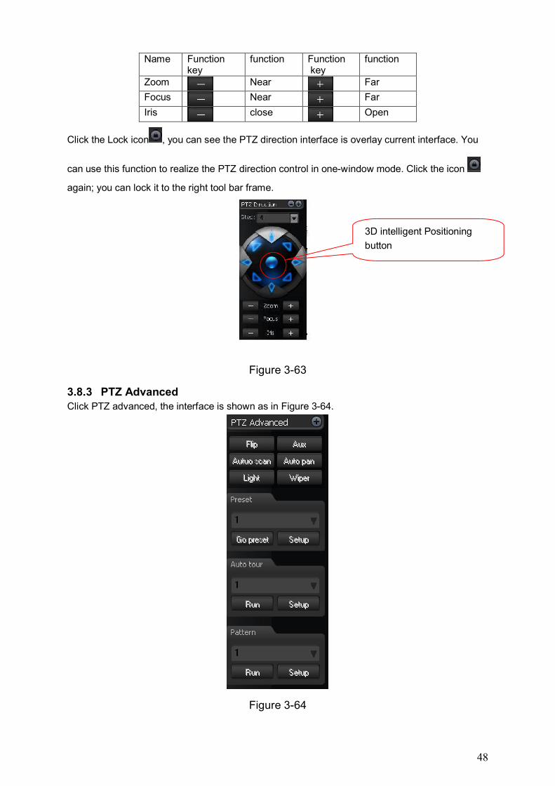
48
Name Function key
function Function key
function
Zoom
Near
Far
Focus
Near
Far
Iris
close
Open
Click the Lock icon , you can see the PTZ direction interface is overlay current interface. You
can use this function to realize the PTZ direction control in one-window mode. Click the icon
again; you can lock it to the right tool bar frame.
Figure 3-63
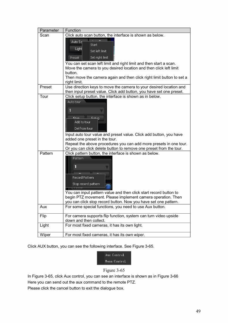
3.8.3 PTZ Advanced Click PTZ advanced, the interface is shown as in Figure 3-64.
Figure 3-64
3D intelligent Positioning
button
49
Parameter Function Scan Click auto scan button, the interface is shown as below.
You can set scan left limit and right limit and then start a scan. Move the camera to you desired location and then click left limit button. Then move the camera again and then click right limit button to set a right limit.
Preset Use direction keys to move the camera to your desired location and then input preset value. Click add button, you have set one preset.
Tour Click setup button, the interface is shown as in below.
Input auto tour value and preset value. Click add button, you have added one preset in the tour. Repeat the above procedures you can add more presets in one tour. Or you can click delete button to remove one preset from the tour.
Pattern Click pattern button, the interface is shown as below.
You can input pattern value and then click start record button to begin PTZ movement. Please implement camera operation. Then you can click stop record button. Now you have set one pattern.
Aux For some special functions, you need to use Aux button.
Flip For camera supports flip function, system can turn video upside down and then collect.
Light For most fixed cameras, it has its own light.
Wiper For most fixed cameras, it has its own wiper.
Click AUX button, you can see the following interface. See Figure 3-65.
Figure 3-65
In Figure 3-65, click Aux control, you can see an interface is shown as in Figure 3-66
Here you can send out the aux command to the remote PTZ.
Please click the cancel button to exit the dialogue box.
50
Figure 3-66
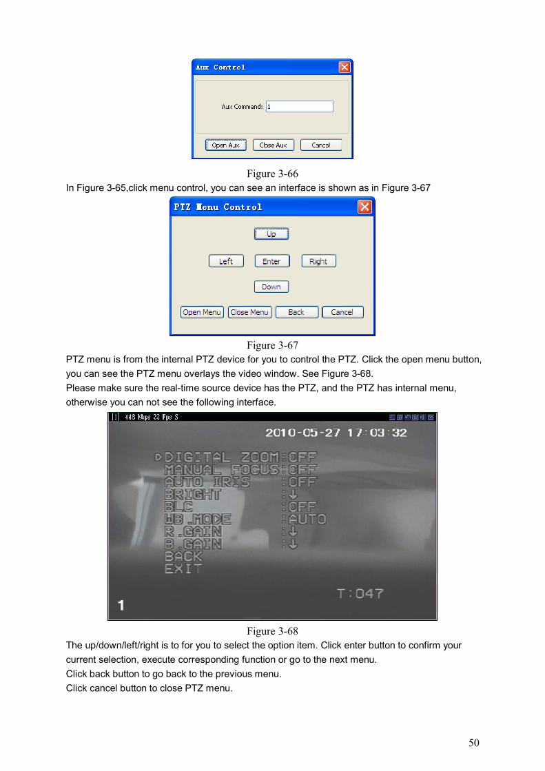
In Figure 3-65,click menu control, you can see an interface is shown as in Figure 3-67
Figure 3-67
PTZ menu is from the internal PTZ device for you to control the PTZ. Click the open menu button,
you can see the PTZ menu overlays the video window. See Figure 3-68.
Please make sure the real-time source device has the PTZ, and the PTZ has internal menu,
otherwise you can not see the following interface.
Figure 3-68
The up/down/left/right is to for you to select the option item. Click enter button to confirm your
current selection, execute corresponding function or go to the next menu.
Click back button to go back to the previous menu.
Click cancel button to close PTZ menu.
51
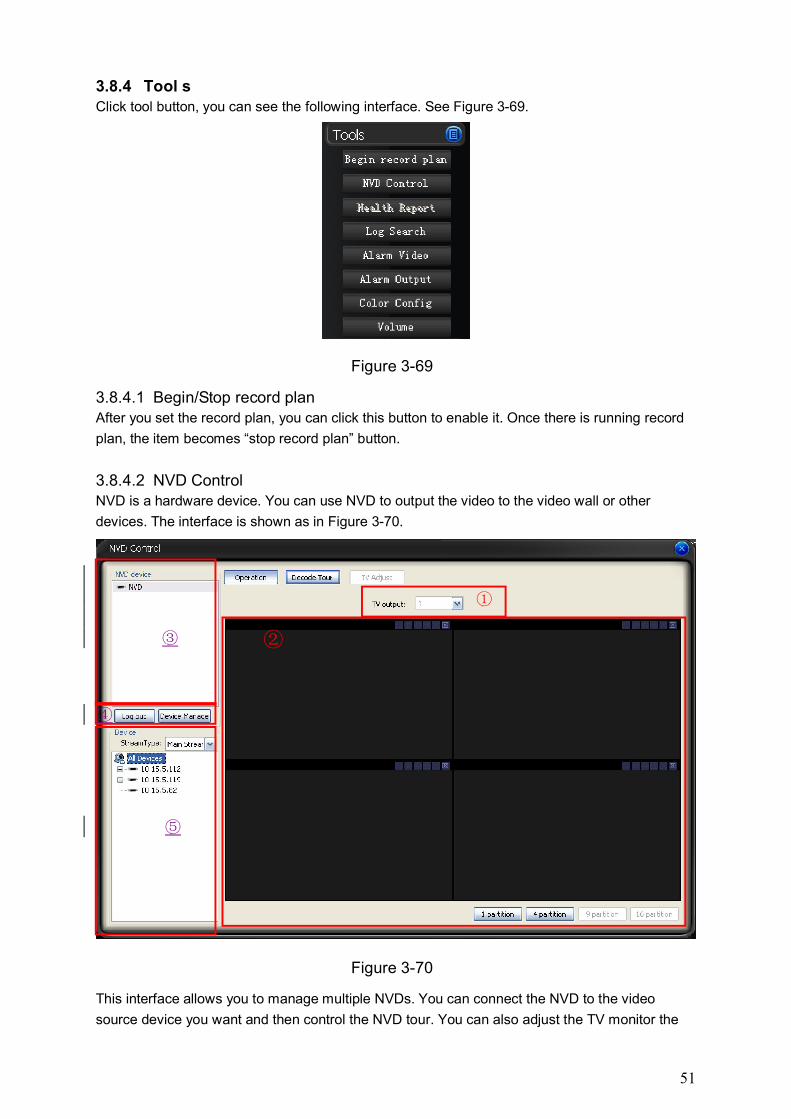
3.8.4 Tool s Click tool button, you can see the following interface. See Figure 3-69.
Figure 3-69
3.8.4.1 Begin/Stop record plan After you set the record plan, you can click this button to enable it. Once there is running record
plan, the item becomes “stop record plan” button.
3.8.4.2 NVD Control NVD is a hardware device. You can use NVD to output the video to the video wall or other
devices. The interface is shown as in Figure 3-70.
Figure 3-70
This interface allows you to manage multiple NVDs. You can connect the NVD to the video
source device you want and then control the NVD tour. You can also adjust the TV monitor the
①
②
③
④
⑤
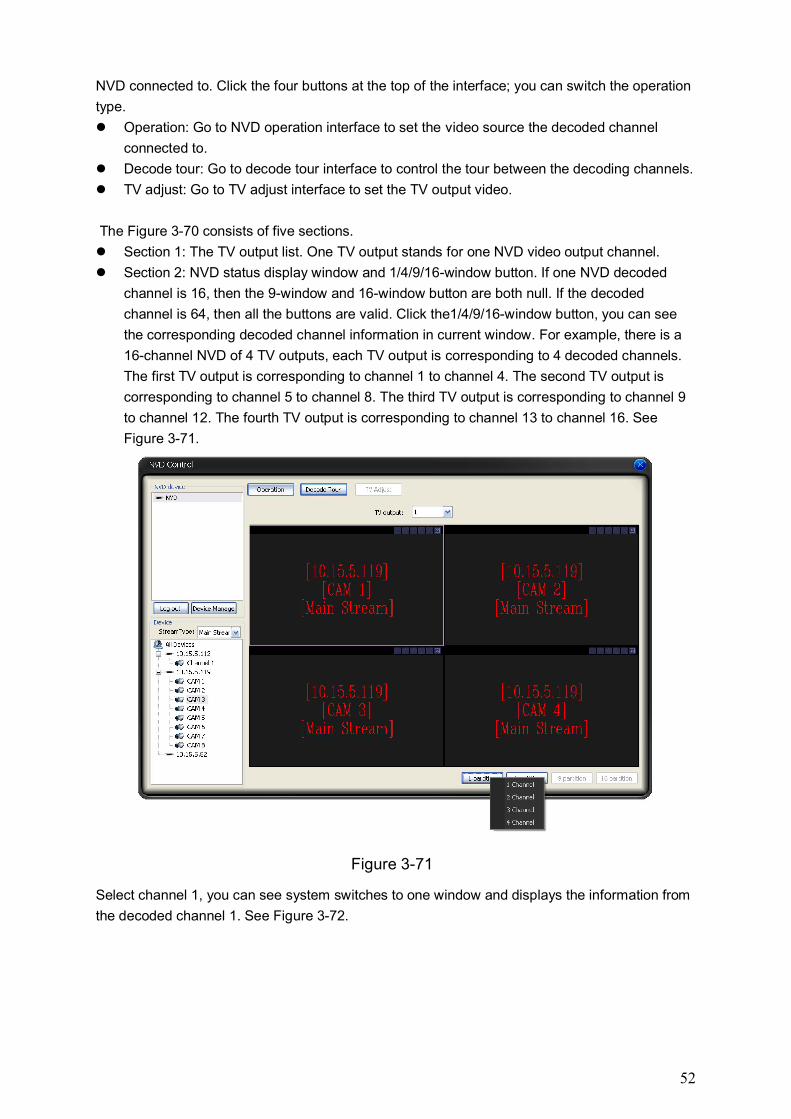
52
NVD connected to. Click the four buttons at the top of the interface; you can switch the operation
type.
Operation: Go to NVD operation interface to set the video source the decoded channel
connected to.
Decode tour: Go to decode tour interface to control the tour between the decoding channels.
TV adjust: Go to TV adjust interface to set the TV output video.
The Figure 3-70 consists of five sections.
Section 1: The TV output list. One TV output stands for one NVD video output channel.
Section 2: NVD status display window and 1/4/9/16-window button. If one NVD decoded
channel is 16, then the 9-window and 16-window button are both null. If the decoded
channel is 64, then all the buttons are valid. Click the1/4/9/16-window button, you can see
the corresponding decoded channel information in current window. For example, there is a
16-channel NVD of 4 TV outputs, each TV output is corresponding to 4 decoded channels.
The first TV output is corresponding to channel 1 to channel 4. The second TV output is
corresponding to channel 5 to channel 8. The third TV output is corresponding to channel 9
to channel 12. The fourth TV output is corresponding to channel 13 to channel 16. See
Figure 3-71.
Figure 3-71
Select channel 1, you can see system switches to one window and displays the information from
the decoded channel 1. See Figure 3-72.
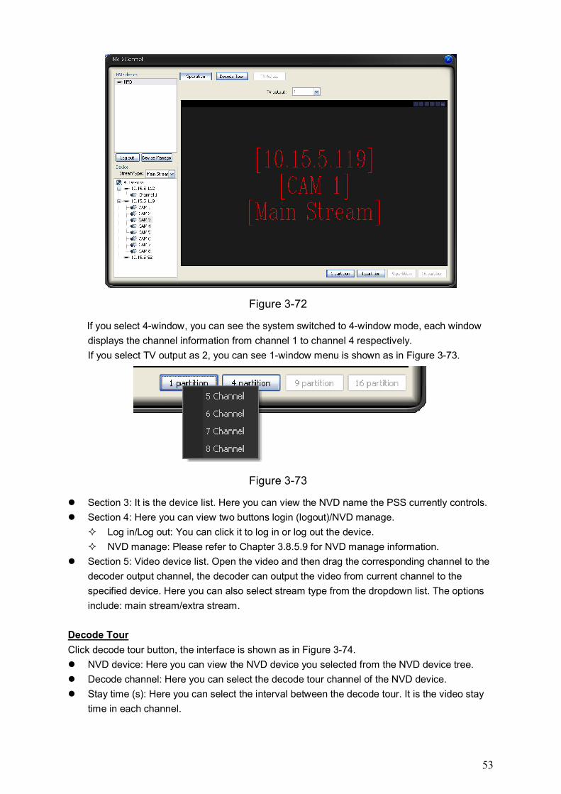
53
Figure 3-72
If you select 4-window, you can see the system switched to 4-window mode, each window
displays the channel information from channel 1 to channel 4 respectively.
If you select TV output as 2, you can see 1-window menu is shown as in Figure 3-73.
Figure 3-73
Section 3: It is the device list. Here you can view the NVD name the PSS currently controls.
Section 4: Here you can view two buttons login (logout)/NVD manage.
Log in/Log out: You can click it to log in or log out the device.
NVD manage: Please refer to Chapter 3.8.5.9 for NVD manage information.
Section 5: Video device list. Open the video and then drag the corresponding channel to the
decoder output channel, the decoder can output the video from current channel to the
specified device. Here you can also select stream type from the dropdown list. The options
include: main stream/extra stream.
Decode Tour
Click decode tour button, the interface is shown as in Figure 3-74.
NVD device: Here you can view the NVD device you selected from the NVD device tree.
Decode channel: Here you can select the decode tour channel of the NVD device.
Stay time (s): Here you can select the interval between the decode tour. It is the video stay
time in each channel.
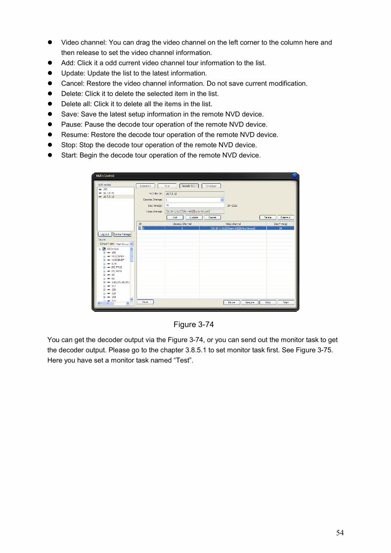
54
Video channel: You can drag the video channel on the left corner to the column here and
then release to set the video channel information.
Add: Click it a odd current video channel tour information to the list.
Update: Update the list to the latest information.
Cancel: Restore the video channel information. Do not save current modification.
Delete: Click it to delete the selected item in the list.
Delete all: Click it to delete all the items in the list.
Save: Save the latest setup information in the remote NVD device.
Pause: Pause the decode tour operation of the remote NVD device.
Resume: Restore the decode tour operation of the remote NVD device.
Stop: Stop the decode tour operation of the remote NVD device.
Start: Begin the decode tour operation of the remote NVD device.
Figure 3-74
You can get the decoder output via the Figure 3-74, or you can send out the monitor task to get
the decoder output. Please go to the chapter 3.8.5.1 to set monitor task first. See Figure 3-75.
Here you have set a monitor task named “Test”.
55
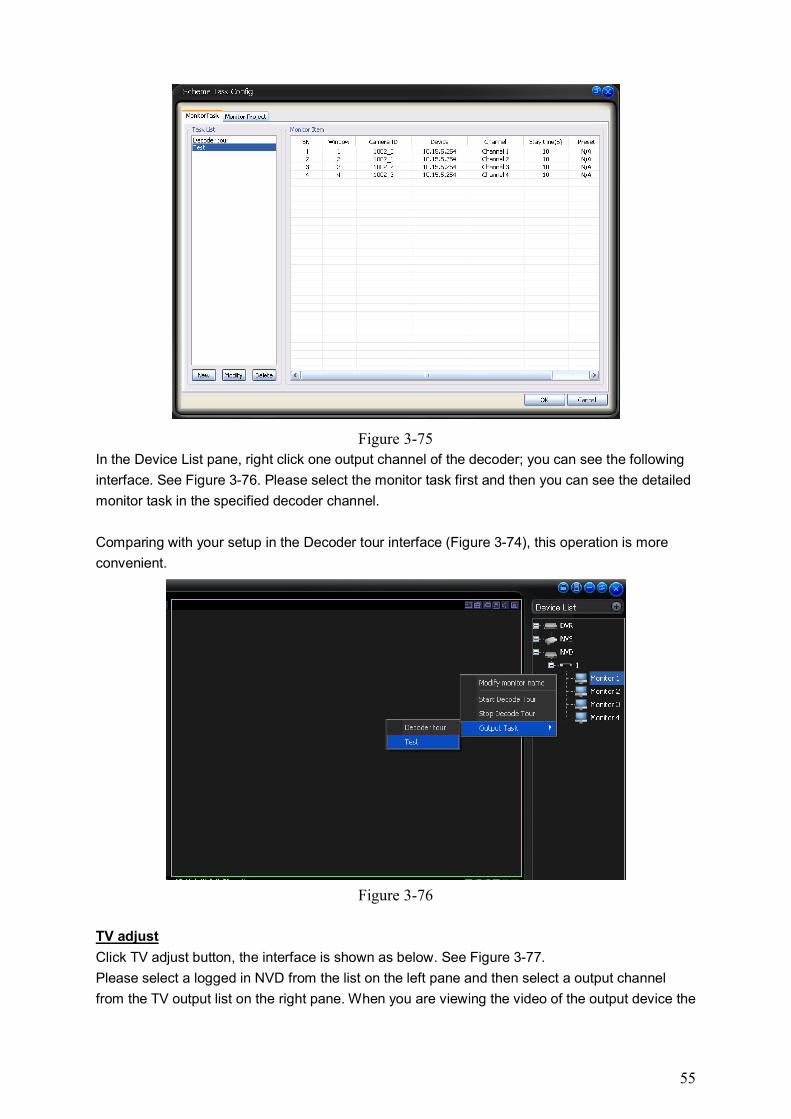
Figure 3-75
In the Device List pane, right click one output channel of the decoder; you can see the following
interface. See Figure 3-76. Please select the monitor task first and then you can see the detailed
monitor task in the specified decoder channel.
Comparing with your setup in the Decoder tour interface (Figure 3-74), this operation is more
convenient.
Figure 3-76
TV adjust
Click TV adjust button, the interface is shown as below. See Figure 3-77.
Please select a logged in NVD from the list on the left pane and then select a output channel
from the TV output list on the right pane. When you are viewing the video of the output device the
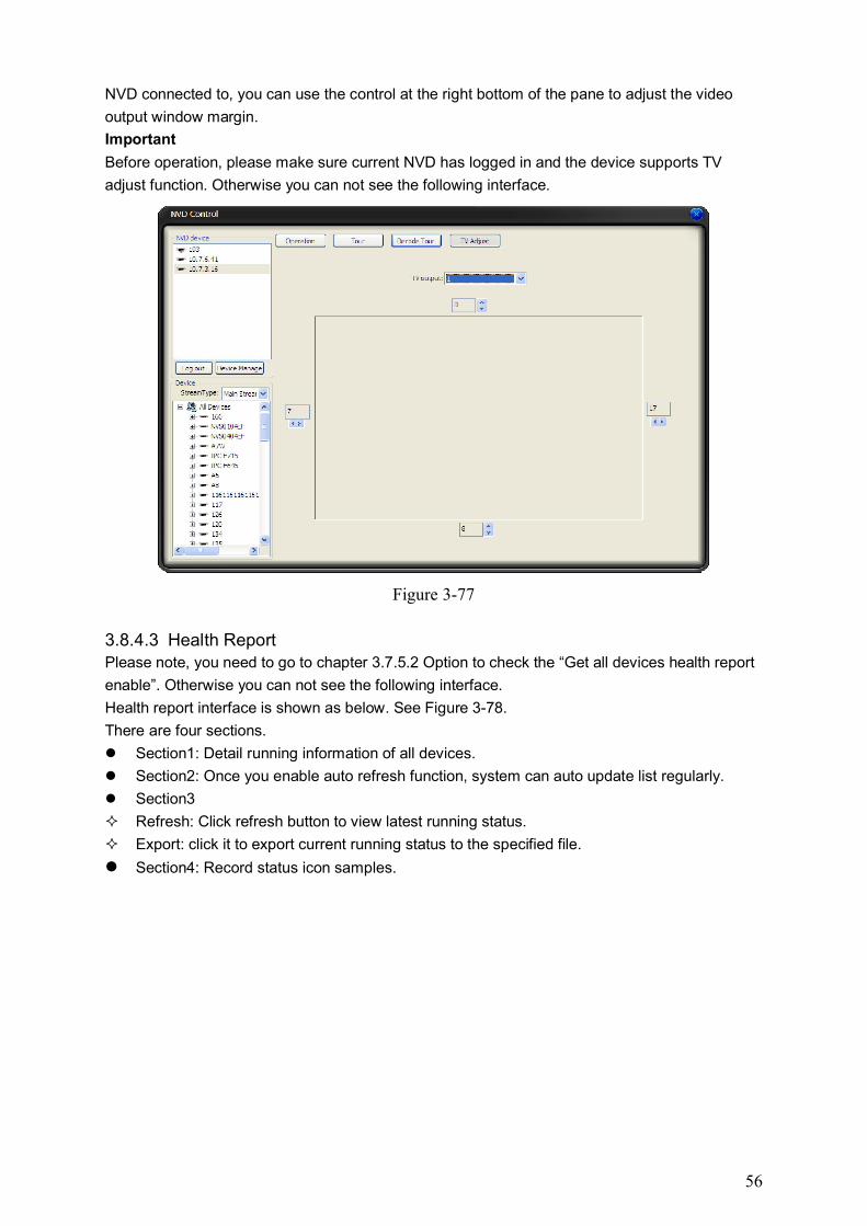
56
NVD connected to, you can use the control at the right bottom of the pane to adjust the video
output window margin.
Important
Before operation, please make sure current NVD has logged in and the device supports TV
adjust function. Otherwise you can not see the following interface.
Figure 3-77
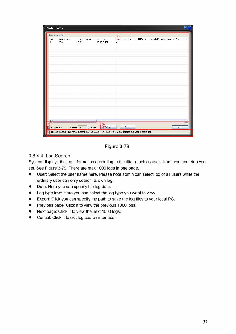
3.8.4.3 Health Report Please note, you need to go to chapter 3.7.5.2 Option to check the “Get all devices health report
enable”. Otherwise you can not see the following interface.
Health report interface is shown as below. See Figure 3-78.
There are four sections.
Section1: Detail running information of all devices.
Section2: Once you enable auto refresh function, system can auto update list regularly.
Section3
Refresh: Click refresh button to view latest running status.
Export: click it to export current running status to the specified file.
Section4: Record status icon samples.
57
Figure 3-78
3.8.4.4 Log Search System displays the log information according to the filter (such as user, time, type and etc.) you
set. See Figure 3-79. There are max 1000 logs in one page.
User: Select the user name here. Please note admin can select log of all users while the
ordinary user can only search its own log.
Date: Here you can specify the log date.
Log type tree: Here you can select the log type you want to view.
Export: Click you can specify the path to save the log files to your local PC.
Previous page: Click it to view the previous 1000 logs.
Next page: Click it to view the next 1000 logs.
Cancel: Click it to exit log search interface.
①
② ③
④
58
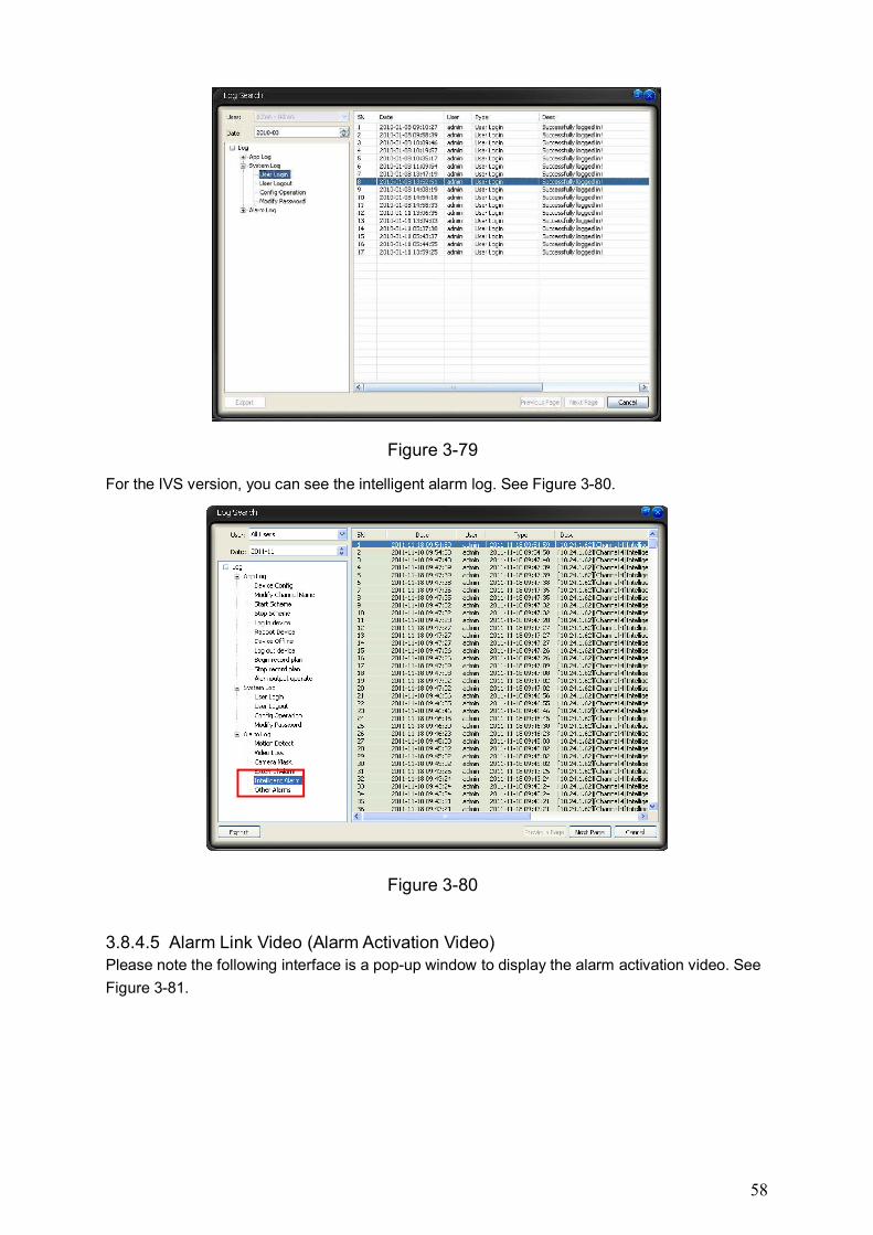
Figure 3-79
For the IVS version, you can see the intelligent alarm log. See Figure 3-80.
Figure 3-80
3.8.4.5 Alarm Link Video (Alarm Activation Video) Please note the following interface is a pop-up window to display the alarm activation video. See
Figure 3-81.
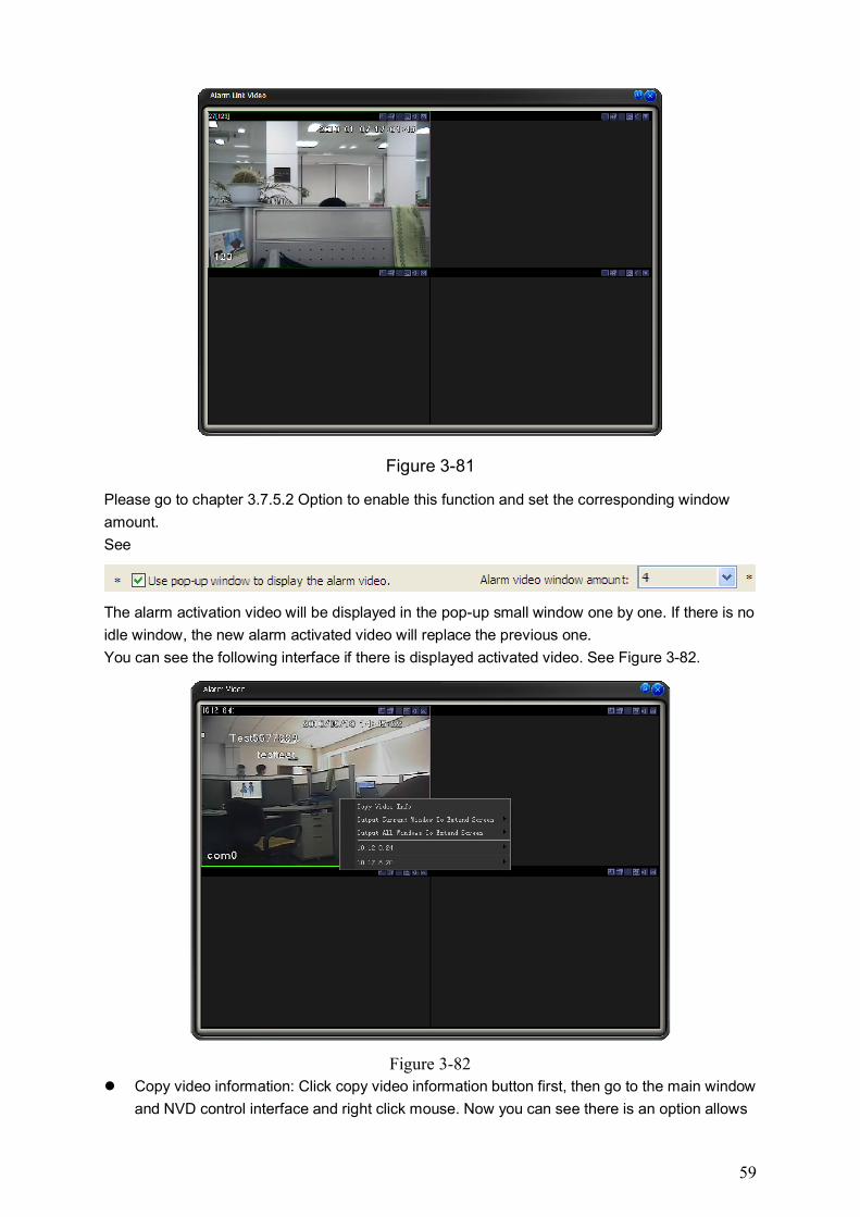
59
Figure 3-81
Please go to chapter 3.7.5.2 Option to enable this function and set the corresponding window
amount.
See
The alarm activation video will be displayed in the pop-up small window one by one. If there is no
idle window, the new alarm activated video will replace the previous one.
You can see the following interface if there is displayed activated video. See Figure 3-82.
Figure 3-82
Copy video information: Click copy video information button first, then go to the main window
and NVD control interface and right click mouse. Now you can see there is an option allows
60
you to paste video information button. Select the paste video information; you can see the
alarm activation video in the corresponding window.
Output current window to the extension screen: There are several extension screen names.
You can click the corresponding name to output the current window to the specified
extension screen. (Important: Please make sure you have added the extension screen,
otherwise you can not see this item.)
Output all windows to the extension screen: There are several extension screen names. You
can click to output all windows to the specified extension screen. (Important: Please make
sure you have added the extension screen, otherwise you can not see this item.)
10.12.8.24 and 10.12.8.20 (The IP address here is for example only. Please make sure you
have connected to the decoder or the SNVD, otherwise you can not see the corresponding
item.): These are the decoder and SNVD name that has logged in. You can select the
connected screen name of the corresponding device from the dropdown list to output the
alarm activation video to the specified screen.
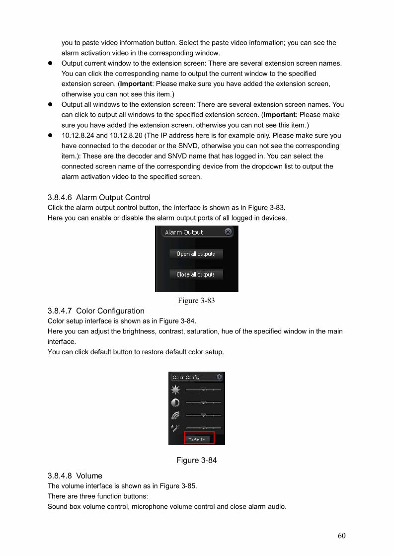
3.8.4.6 Alarm Output Control Click the alarm output control button, the interface is shown as in Figure 3-83.
Here you can enable or disable the alarm output ports of all logged in devices.
Figure 3-83
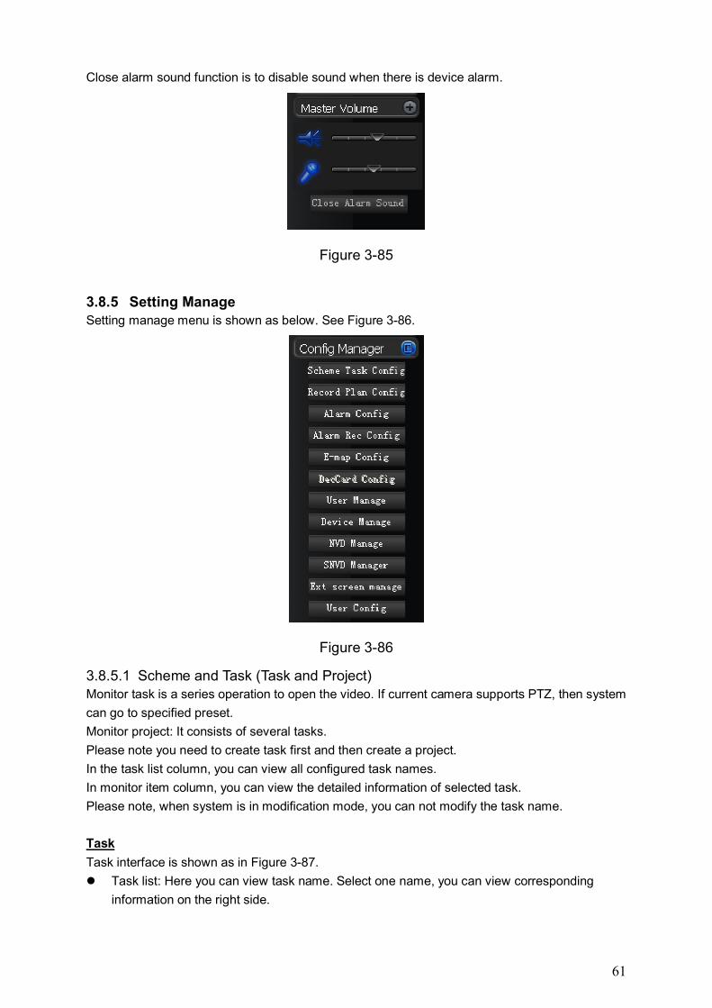
3.8.4.7 Color Configuration Color setup interface is shown as in Figure 3-84.
Here you can adjust the brightness, contrast, saturation, hue of the specified window in the main
interface.
You can click default button to restore default color setup.
Figure 3-84
3.8.4.8 Volume The volume interface is shown as in Figure 3-85.
There are three function buttons:
Sound box volume control, microphone volume control and close alarm audio.
61
Close alarm sound function is to disable sound when there is device alarm.
Figure 3-85
3.8.5 Setting Manage Setting manage menu is shown as below. See Figure 3-86.
Figure 3-86
3.8.5.1 Scheme and Task (Task and Project) Monitor task is a series operation to open the video. If current camera supports PTZ, then system
can go to specified preset.
Monitor project: It consists of several tasks.
Please note you need to create task first and then create a project.
In the task list column, you can view all configured task names.
In monitor item column, you can view the detailed information of selected task.
Please note, when system is in modification mode, you can not modify the task name.
Task
Task interface is shown as in Figure 3-87.
Task list: Here you can view task name. Select one name, you can view corresponding
information on the right side.
62
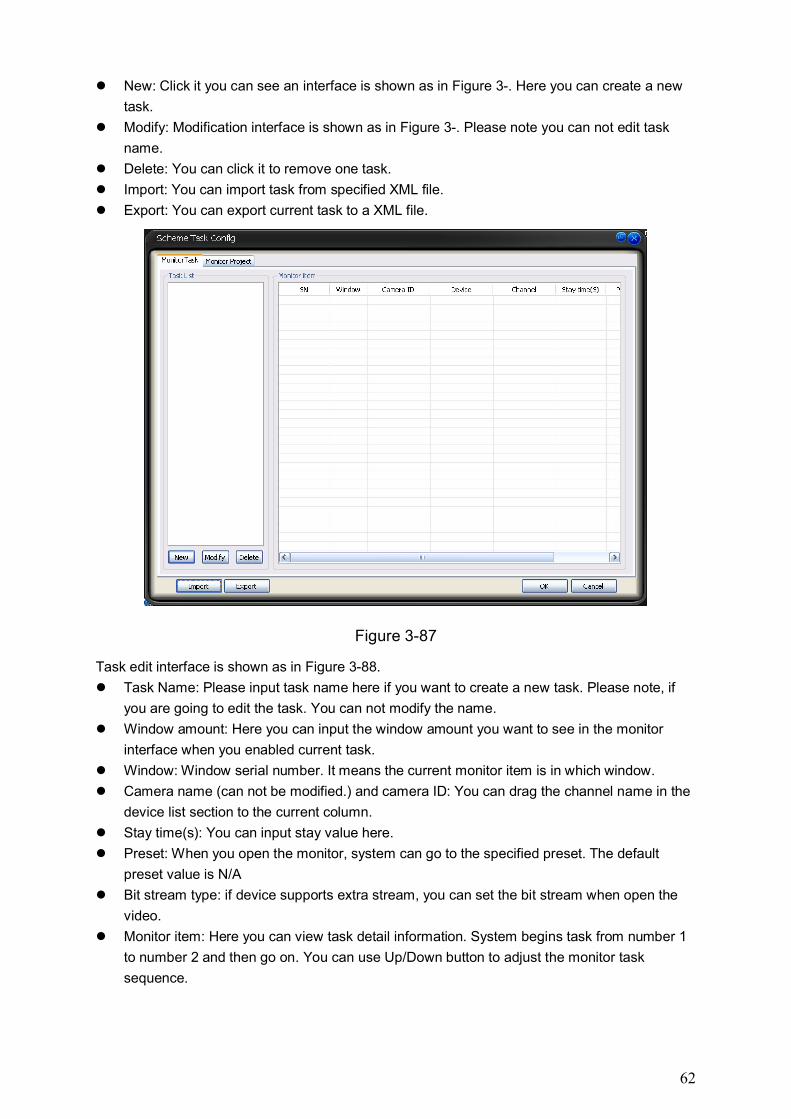
New: Click it you can see an interface is shown as in Figure 3-. Here you can create a new
task.
Modify: Modification interface is shown as in Figure 3-. Please note you can not edit task
name.
Delete: You can click it to remove one task.
Import: You can import task from specified XML file.
Export: You can export current task to a XML file.
Figure 3-87
Task edit interface is shown as in Figure 3-88.
Task Name: Please input task name here if you want to create a new task. Please note, if
you are going to edit the task. You can not modify the name.
Window amount: Here you can input the window amount you want to see in the monitor
interface when you enabled current task.
Window: Window serial number. It means the current monitor item is in which window.
Camera name (can not be modified.) and camera ID: You can drag the channel name in the
device list section to the current column.
Stay time(s): You can input stay value here.
Preset: When you open the monitor, system can go to the specified preset. The default
preset value is N/A
Bit stream type: if device supports extra stream, you can set the bit stream when open the
video.
Monitor item: Here you can view task detail information. System begins task from number 1
to number 2 and then go on. You can use Up/Down button to adjust the monitor task
sequence.
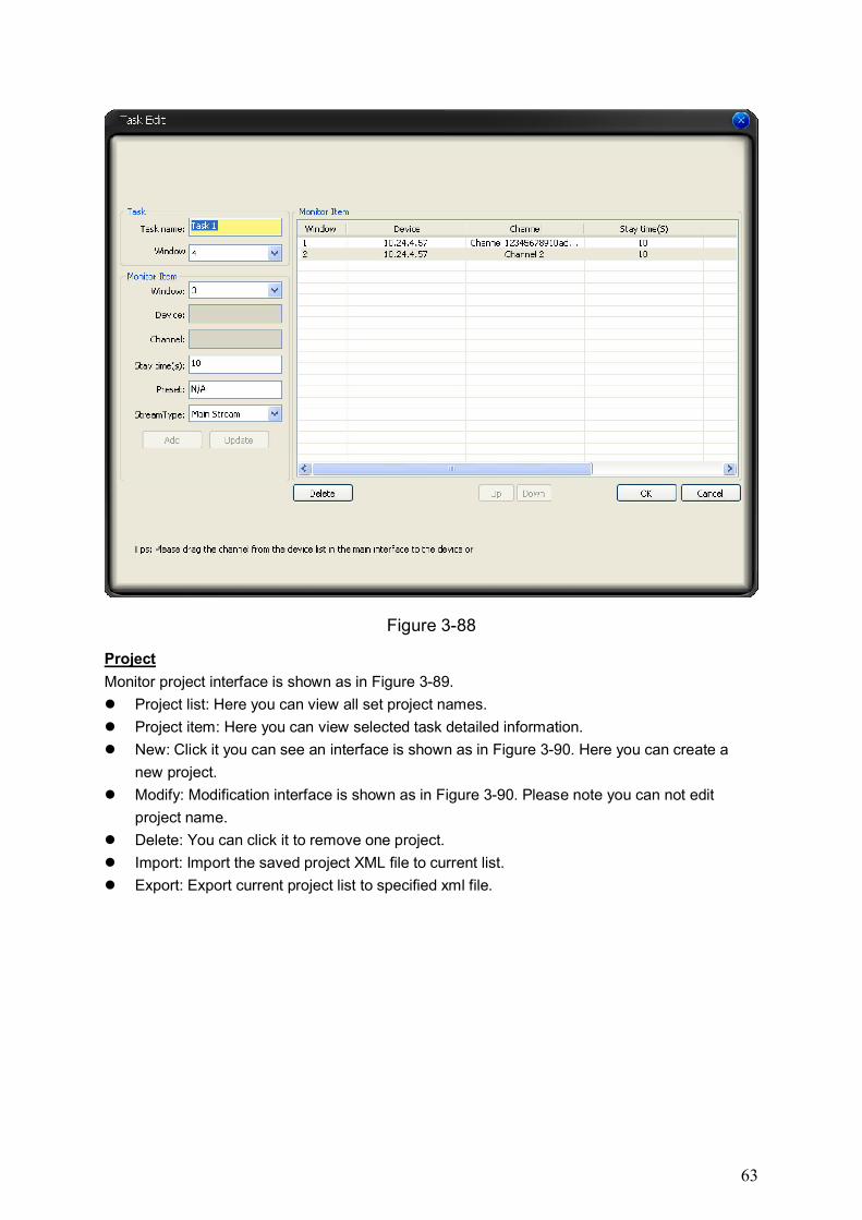
63
Figure 3-88
Project
Monitor project interface is shown as in Figure 3-89.
Project list: Here you can view all set project names.
Project item: Here you can view selected task detailed information.
New: Click it you can see an interface is shown as in Figure 3-90. Here you can create a
new project.
Modify: Modification interface is shown as in Figure 3-90. Please note you can not edit
project name.
Delete: You can click it to remove one project.
Import: Import the saved project XML file to current list.
Export: Export current project list to specified xml file.
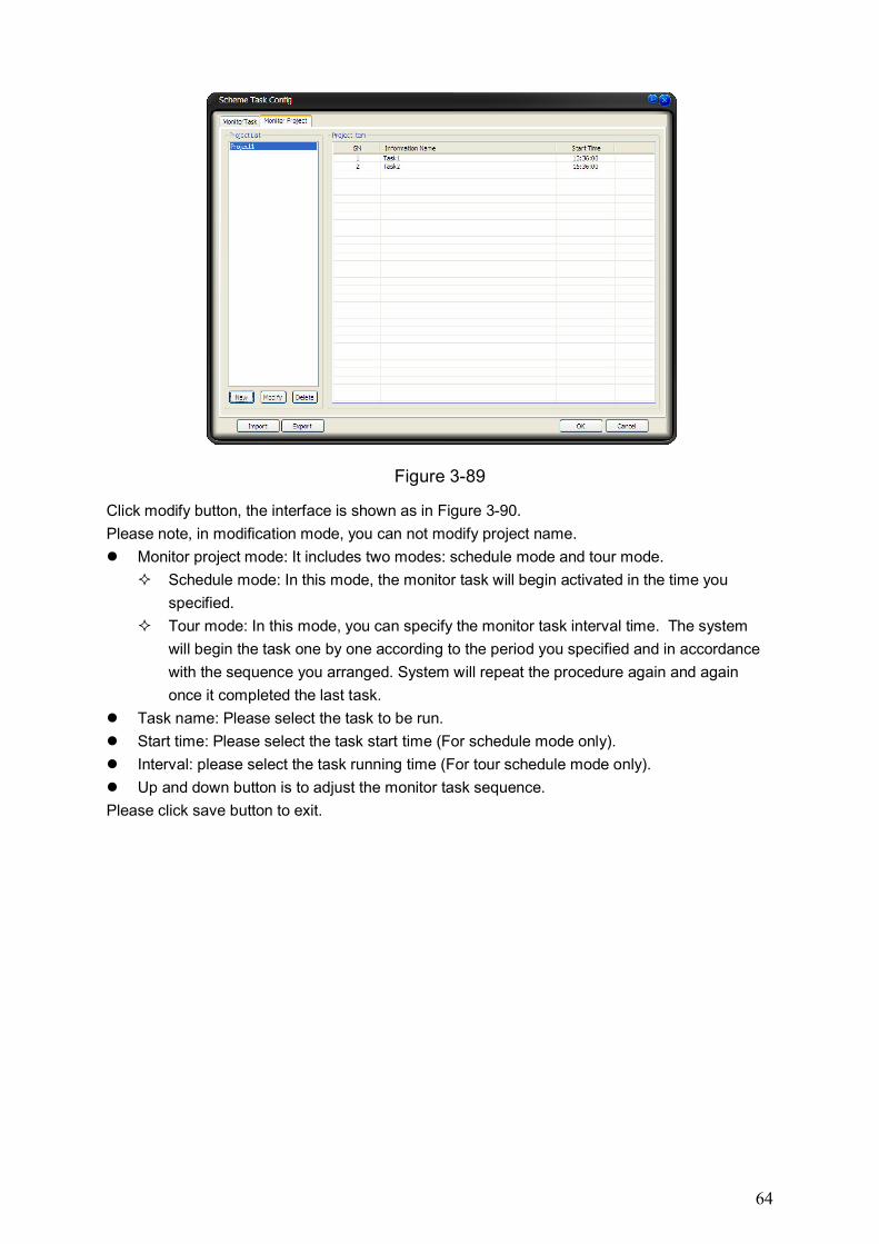
64
Figure 3-89
Click modify button, the interface is shown as in Figure 3-90.
Please note, in modification mode, you can not modify project name.
Monitor project mode: It includes two modes: schedule mode and tour mode.
Schedule mode: In this mode, the monitor task will begin activated in the time you
specified.
Tour mode: In this mode, you can specify the monitor task interval time. The system
will begin the task one by one according to the period you specified and in accordance
with the sequence you arranged. System will repeat the procedure again and again
once it completed the last task.
Task name: Please select the task to be run.
Start time: Please select the task start time (For schedule mode only).
Interval: please select the task running time (For tour schedule mode only).
Up and down button is to adjust the monitor task sequence.
Please click save button to exit.
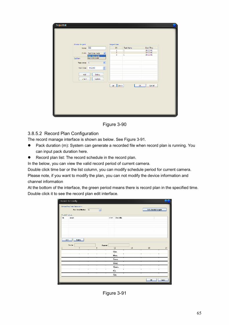
65
Figure 3-90
3.8.5.2 Record Plan Configuration The record manage interface is shown as below. See Figure 3-91.
Pack duration (m): System can generate a recorded file when record plan is running. You
can input pack duration here.
Record plan list: The record schedule in the record plan.
In the below, you can view the valid record period of current camera.
Double click time bar or the list column, you can modify schedule period for current camera.
Please note, if you want to modify the plan, you can not modify the device information and
channel information
At the bottom of the interface, the green period means there is record plan in the specified time.
Double click it to see the record plan edit interface.
Figure 3-91
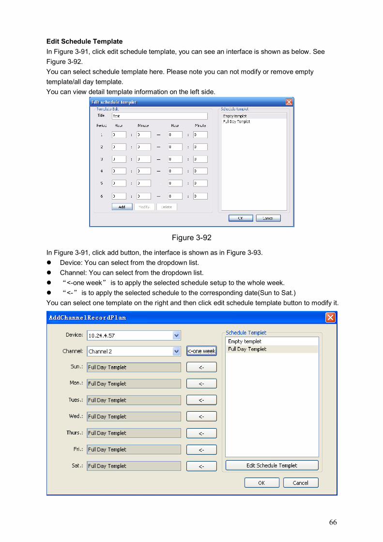
66
Edit Schedule Template
In Figure 3-91, click edit schedule template, you can see an interface is shown as below. See
Figure 3-92.
You can select schedule template here. Please note you can not modify or remove empty
template/all day template.
You can view detail template information on the left side.
Figure 3-92
In Figure 3-91, click add button, the interface is shown as in Figure 3-93.
Device: You can select from the dropdown list.
Channel: You can select from the dropdown list.
“<-one week” is to apply the selected schedule setup to the whole week.
“<-” is to apply the selected schedule to the corresponding date(Sun to Sat.)
You can select one template on the right and then click edit schedule template button to modify it.
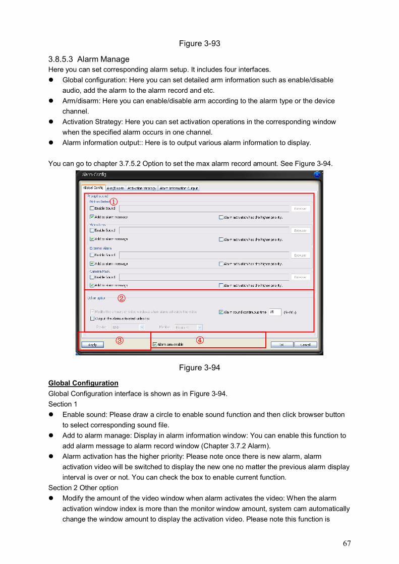
67
Figure 3-93
3.8.5.3 Alarm Manage Here you can set corresponding alarm setup. It includes four interfaces.
Global configuration: Here you can set detailed arm information such as enable/disable
audio, add the alarm to the alarm record and etc.
Arm/disarm: Here you can enable/disable arm according to the alarm type or the device
channel.
Activation Strategy: Here you can set activation operations in the corresponding window
when the specified alarm occurs in one channel.
Alarm information output:: Here is to output various alarm information to display.
You can go to chapter 3.7.5.2 Option to set the max alarm record amount. See Figure 3-94.
Figure 3-94
Global Configuration
Global Configuration interface is shown as in Figure 3-94.
Section 1
Enable sound: Please draw a circle to enable sound function and then click browser button
to select corresponding sound file.
Add to alarm manage: Display in alarm information window: You can enable this function to
add alarm message to alarm record window (Chapter 3.7.2 Alarm).
Alarm activation has the higher priority: Please note once there is new alarm, alarm
activation video will be switched to display the new one no matter the previous alarm display
interval is over or not. You can check the box to enable current function.
Section 2 Other option
Modify the amount of the video window when alarm activates the video: When the alarm
activation window index is more than the monitor window amount, system cam automatically
change the window amount to display the activation video. Please note this function is
①
②
③ ④
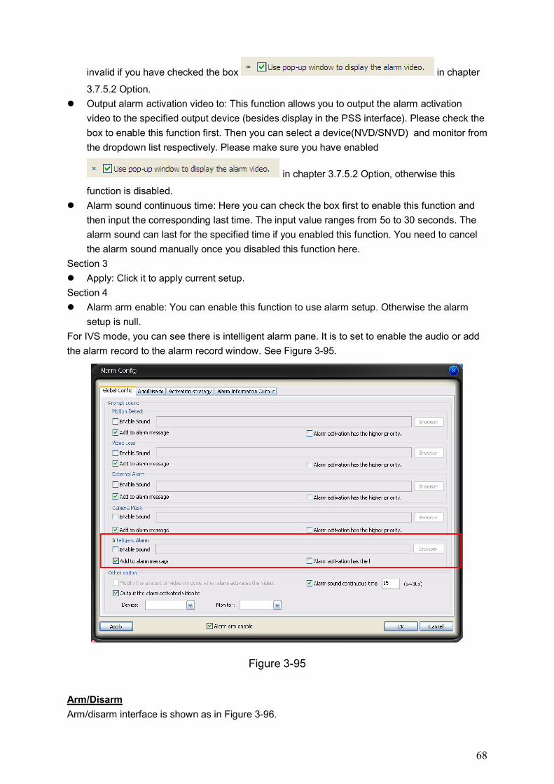
68
invalid if you have checked the box in chapter
3.7.5.2 Option.
Output alarm activation video to: This function allows you to output the alarm activation
video to the specified output device (besides display in the PSS interface). Please check the
box to enable this function first. Then you can select a device(NVD/SNVD) and monitor from
the dropdown list respectively. Please make sure you have enabled
in chapter 3.7.5.2 Option, otherwise this
function is disabled.
Alarm sound continuous time: Here you can check the box first to enable this function and
then input the corresponding last time. The input value ranges from 5o to 30 seconds. The
alarm sound can last for the specified time if you enabled this function. You need to cancel
the alarm sound manually once you disabled this function here.
Section 3
Apply: Click it to apply current setup.
Section 4
Alarm arm enable: You can enable this function to use alarm setup. Otherwise the alarm
setup is null.
For IVS mode, you can see there is intelligent alarm pane. It is to set to enable the audio or add
the alarm record to the alarm record window. See Figure 3-95.
Figure 3-95
Arm/Disarm
Arm/disarm interface is shown as in Figure 3-96.
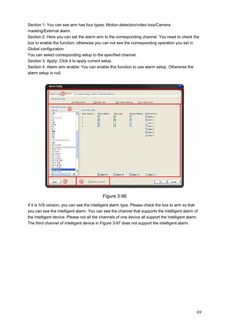
69
Section 1: You can see arm has four types: Motion detection/video loss/Camera
masking/External alarm.
Section 2: Here you can set the alarm arm to the corresponding channel. You need to check the
box to enable the function; otherwise you can not see the corresponding operation you set in
Global configuration
You can select corresponding setup to the specified channel.
Section 3: Apply: Click it to apply current setup.
Section 4: Alarm arm enable: You can enable this function to use alarm setup. Otherwise the
alarm setup is null.
Figure 3-96
If it is IVS version, you can see the intelligent alarm type. Please check the box to arm so that
you can see the intelligent alarm. You can see the channel that supports the intelligent alarm of
the intelligent device. Please not all the channels of one device all support the intelligent alarm.
The third channel of intelligent device in Figure 3-97 does not support the intelligent alarm.
①
②
③ ④
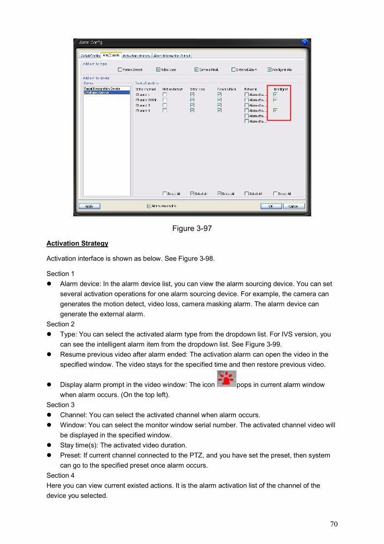
70
Figure 3-97
Activation Strategy
Activation interface is shown as below. See Figure 3-98.
Section 1
Alarm device: In the alarm device list, you can view the alarm sourcing device. You can set
several activation operations for one alarm sourcing device. For example, the camera can
generates the motion detect, video loss, camera masking alarm. The alarm device can
generate the external alarm.
Section 2
Type: You can select the activated alarm type from the dropdown list. For IVS version, you
can see the intelligent alarm item from the dropdown list. See Figure 3-99.
Resume previous video after alarm ended: The activation alarm can open the video in the
specified window. The video stays for the specified time and then restore previous video.
Display alarm prompt in the video window: The icon pops in current alarm window
when alarm occurs. (On the top left).
Section 3
Channel: You can select the activated channel when alarm occurs.
Window: You can select the monitor window serial number. The activated channel video will
be displayed in the specified window.
Stay time(s): The activated video duration.
Preset: If current channel connected to the PTZ, and you have set the preset, then system
can go to the specified preset once alarm occurs.
Section 4
Here you can view current existed actions. It is the alarm activation list of the channel of the
device you selected.
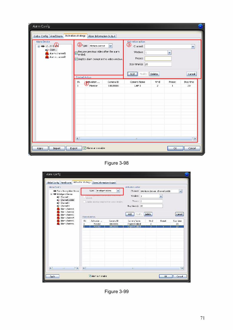
71
Figure 3-98
Figure 3-99
① ② ③
④
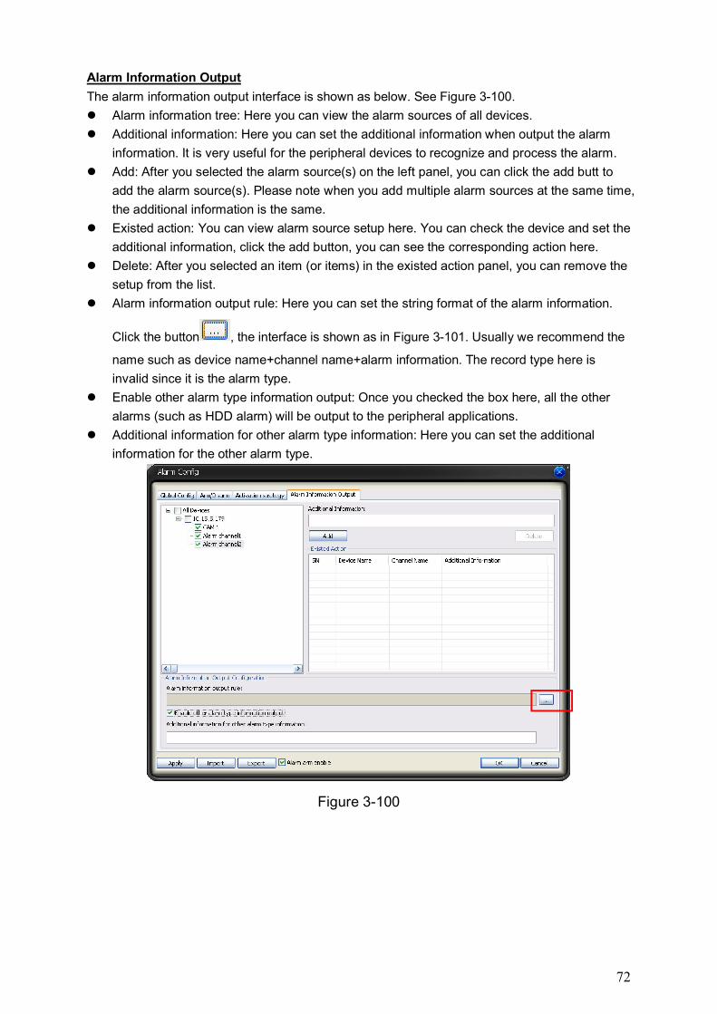
72
Alarm Information Output
The alarm information output interface is shown as below. See Figure 3-100.
Alarm information tree: Here you can view the alarm sources of all devices.
Additional information: Here you can set the additional information when output the alarm
information. It is very useful for the peripheral devices to recognize and process the alarm.
Add: After you selected the alarm source(s) on the left panel, you can click the add butt to
add the alarm source(s). Please note when you add multiple alarm sources at the same time,
the additional information is the same.
Existed action: You can view alarm source setup here. You can check the device and set the
additional information, click the add button, you can see the corresponding action here.
Delete: After you selected an item (or items) in the existed action panel, you can remove the
setup from the list.
Alarm information output rule: Here you can set the string format of the alarm information.
Click the button , the interface is shown as in Figure 3-101. Usually we recommend the
name such as device name+channel name+alarm information. The record type here is
invalid since it is the alarm type.
Enable other alarm type information output: Once you checked the box here, all the other
alarms (such as HDD alarm) will be output to the peripheral applications.
Additional information for other alarm type information: Here you can set the additional
information for the other alarm type.
Figure 3-100
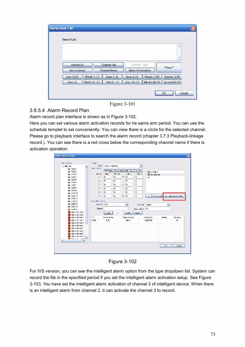
73
Figure 3-101
3.8.5.4 Alarm Record Plan Alarm record plan interface is shown as in Figure 3-102.
Here you can set various alarm activation records for he same arm period. You can use the
schedule templet to set conveniently. You can view there is a circle for the selected channel.
Please go to playback interface to search the alarm record (chapter 3.7.3 Playback-linkage
record.). You can see there is a red cross below the corresponding channel name if there is
activation operation.
Figure 3-102
For IVS version, you can see the intelligent alarm option from the type dropdown list. System can
record the file in the specified period if you set the intelligent alarm activation setup. See Figure
3-103. You have set the intelligent alarm activation of channel 2 of intelligent device. When there
is an intelligent alarm from channel 2, it can activate the channel 3 to record.
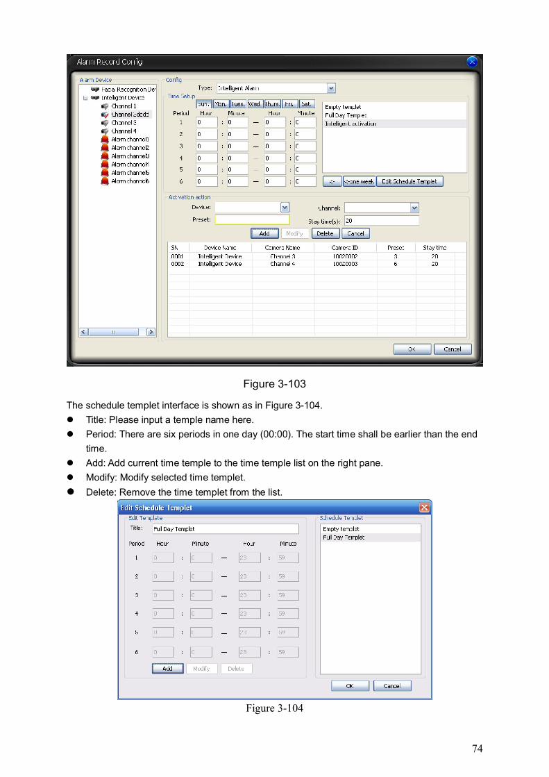
74
Figure 3-103
The schedule templet interface is shown as in Figure 3-104.
Title: Please input a temple name here.
Period: There are six periods in one day (00:00). The start time shall be earlier than the end
time.
Add: Add current time temple to the time temple list on the right pane.
Modify: Modify selected time templet.
Delete: Remove the time templet from the list.
Figure 3-104
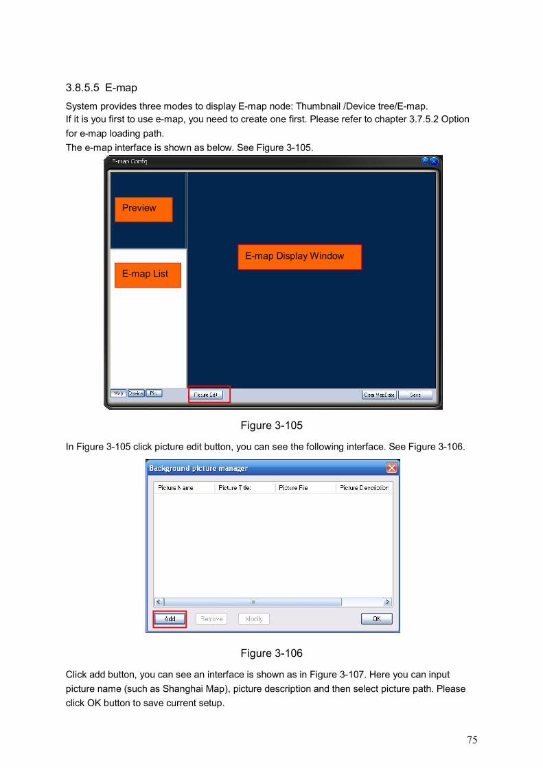
75
3.8.5.5 E-map
System provides three modes to display E-map node: Thumbnail /Device tree/E-map.
If it is you first to use e-map, you need to create one first. Please refer to chapter 3.7.5.2 Option
for e-map loading path.
The e-map interface is shown as below. See Figure 3-105.
Figure 3-105
In Figure 3-105 click picture edit button, you can see the following interface. See Figure 3-106.
Figure 3-106
Click add button, you can see an interface is shown as in Figure 3-107. Here you can input
picture name (such as Shanghai Map), picture description and then select picture path. Please
click OK button to save current setup.
Preview
E-map List
E-map Display Window
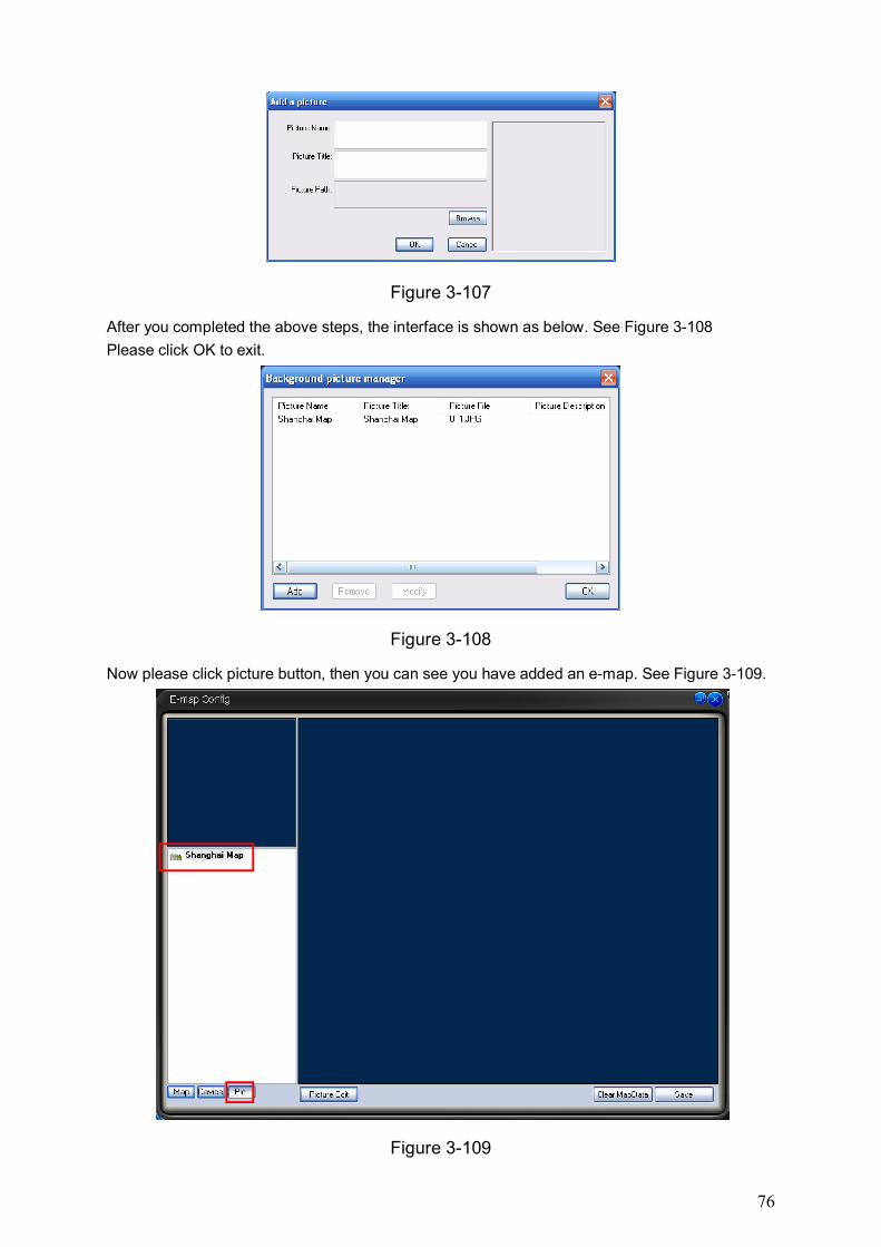
76
Figure 3-107
After you completed the above steps, the interface is shown as below. See Figure 3-108
Please click OK to exit.
Figure 3-108
Now please click picture button, then you can see you have added an e-map. See Figure 3-109.
Figure 3-109
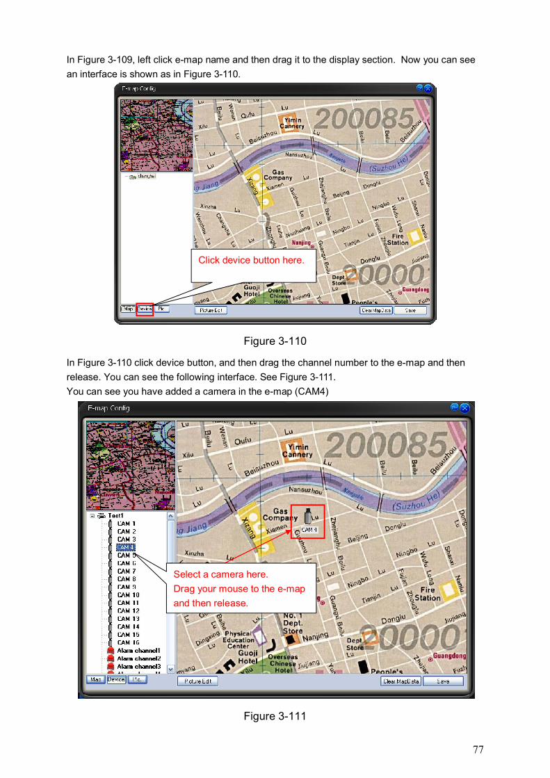
77
In Figure 3-109, left click e-map name and then drag it to the display section. Now you can see
an interface is shown as in Figure 3-110.
Figure 3-110
In Figure 3-110 click device button, and then drag the channel number to the e-map and then
release. You can see the following interface. See Figure 3-111.
You can see you have added a camera in the e-map (CAM4)
Figure 3-111
Click device button here.
Select a camera here.
Drag your mouse to the e-map
and then release.
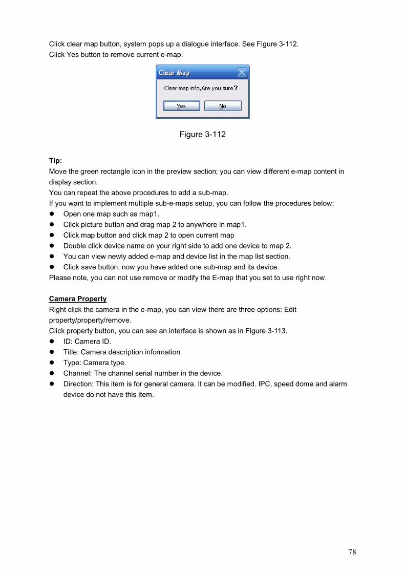
78
Click clear map button, system pops up a dialogue interface. See Figure 3-112.
Click Yes button to remove current e-map.
Figure 3-112
Tip:
Move the green rectangle icon in the preview section; you can view different e-map content in
display section.
You can repeat the above procedures to add a sub-map.
If you want to implement multiple sub-e-maps setup, you can follow the procedures below:
Open one map such as map1.
Click picture button and drag map 2 to anywhere in map1.
Click map button and click map 2 to open current map
Double click device name on your right side to add one device to map 2.
You can view newly added e-map and device list in the map list section.
Click save button, now you have added one sub-map and its device.
Please note, you can not use remove or modify the E-map that you set to use right now.
Camera Property
Right click the camera in the e-map, you can view there are three options: Edit
property/property/remove.
Click property button, you can see an interface is shown as in Figure 3-113.
ID: Camera ID.
Title: Camera description information
Type: Camera type.
Channel: The channel serial number in the device.
Direction: This item is for general camera. It can be modified. IPC, speed dome and alarm
device do not have this item.
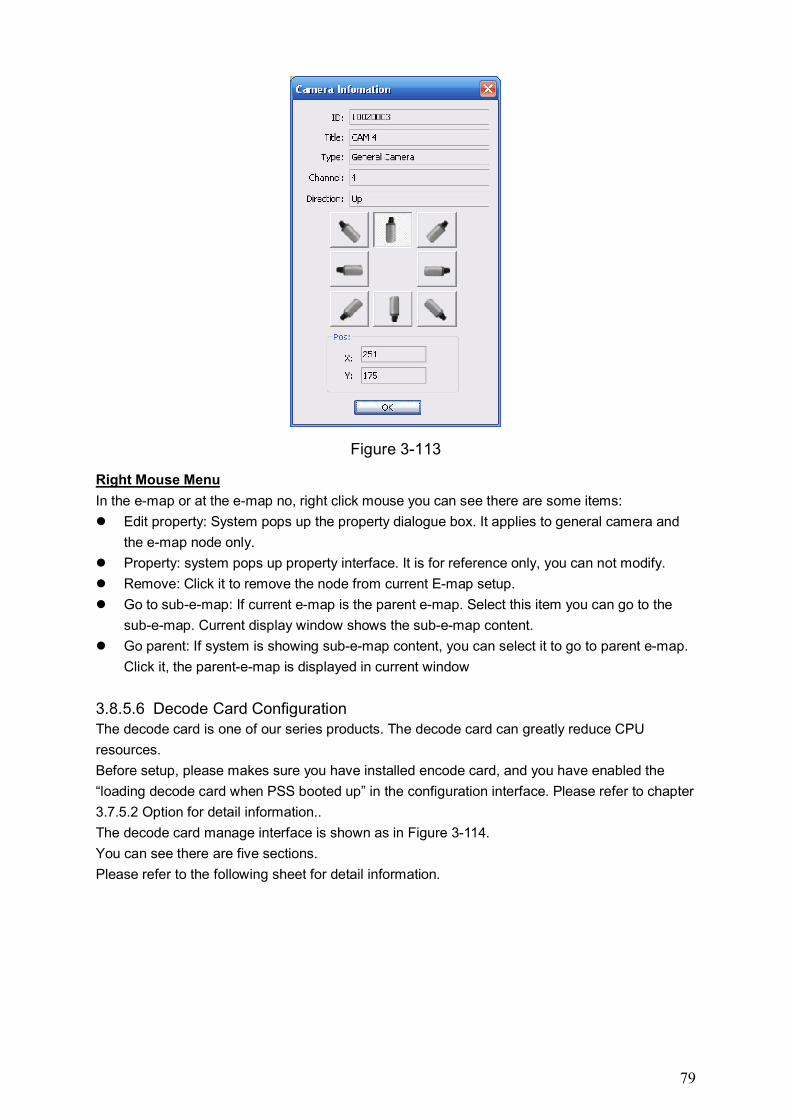
79
Figure 3-113
Right Mouse Menu
In the e-map or at the e-map no, right click mouse you can see there are some items:
Edit property: System pops up the property dialogue box. It applies to general camera and
the e-map node only.
Property: system pops up property interface. It is for reference only, you can not modify.
Remove: Click it to remove the node from current E-map setup.
Go to sub-e-map: If current e-map is the parent e-map. Select this item you can go to the
sub-e-map. Current display window shows the sub-e-map content.
Go parent: If system is showing sub-e-map content, you can select it to go to parent e-map.
Click it, the parent-e-map is displayed in current window
3.8.5.6 Decode Card Configuration The decode card is one of our series products. The decode card can greatly reduce CPU
resources.
Before setup, please makes sure you have installed encode card, and you have enabled the
“loading decode card when PSS booted up” in the configuration interface. Please refer to chapter
3.7.5.2 Option for detail information..
The decode card manage interface is shown as in Figure 3-114.
You can see there are five sections.
Please refer to the following sheet for detail information.
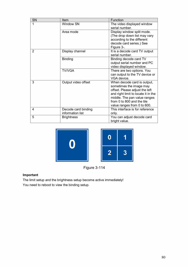
80
SN Item Function 1 Window SN The video displayed window
serial number. Area mode Display window split mode.
(The drop down list may vary according to the different decode card series.) See Figure 3-.
2 Display channel It is a decode card TV output serial number.
Binding Binding decode card TV output serial number and PC video displayed window.
TV/VGA There are two options. You can output to the TV device or VGA device.
3 Output video offset When decode card is output, sometimes the image may offset. Please adjust the left and right limit to locate it in the middle. The pan value ranges from 0 to 800 and the tile value ranges from 0 to 600.
4 Decode card binding information list
This interface is for reference only.
5 Brightness You can adjust decode card bright value.
Figure 3-114
Important
The limit setup and the brightness setup become active immediately!
You need to reboot to view the binding setup.
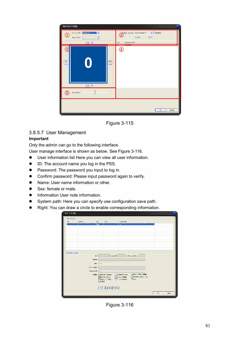
81
Figure 3-115
3.8.5.7 User Management Important
Only the admin can go to the following interface.
User manage interface is shown as below. See Figure 3-116.
User information list Here you can view all user information.
ID: The account name you log in the PSS.
Password: The password you input to log in.
Confirm password: Please input password again to verify.
Name: User name information or other.
Sex: female or male.
Information User note information.
System path: Here you can specify use configuration save path.
Right: You can draw a circle to enable corresponding information.
Figure 3-116
① ②
③
⑤
④
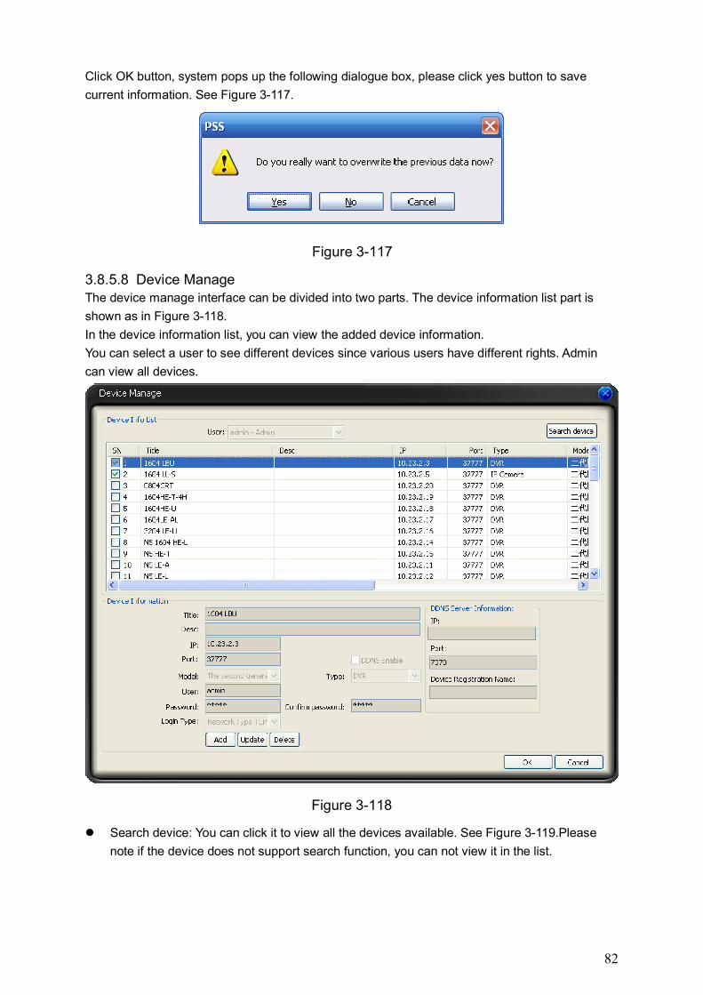
82
Click OK button, system pops up the following dialogue box, please click yes button to save
current information. See Figure 3-117.
Figure 3-117
3.8.5.8 Device Manage The device manage interface can be divided into two parts. The device information list part is
shown as in Figure 3-118.
In the device information list, you can view the added device information.
You can select a user to see different devices since various users have different rights. Admin
can view all devices.
Figure 3-118
Search device: You can click it to view all the devices available. See Figure 3-119.Please
note if the device does not support search function, you can not view it in the list.
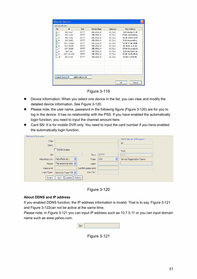
83
Figure 3-119
Device information: When you select one device in the list, you can view and modify the
detailed device information. See Figure 3-120.
Please note, the user name, password in the following figure (Figure 3-120) are for you to
log in the device. It has no relationship with the PSS. If you have enabled the automatically
login function, you need to input the channel amount here.
Card SN: It is for mobile DVR only. You need to input the card number if you have enabled
the automatically login function.
Figure 3-120
About DDNS and IP address
If you enabled DDNS function, the IP address information is invalid. That is to say, Figure 3-121
and Figure 3-122can not be active at the same time.
Please note, in Figure 3-121 you can input IP address such as 10.7.5.11 or you can input domain
name such as www.yahoo.com.
Figure 3-121
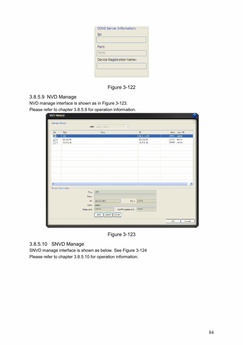
84
Figure 3-122
3.8.5.9 NVD Manage NVD manage interface is shown as in Figure 3-123.
Please refer to chapter 3.8.5.9 for operation information.
Figure 3-123
3.8.5.10 SNVD Manage SNVD manage interface is shown as below. See Figure 3-124
Please refer to chapter 3.8.5.10 for operation information.

85
Figure 3-124
Important
User name and password here is for you to login the device. It has no relationship with our
software operation!
3.8.5.11 Extension Screen You can output your Windows interface to several monitors via multiple display cards or the
display card supports several output ports. PSS can output the video interface to max four
monitors, including one main monitor (display PSS main interface) and three extension monitors.
The extension monitor can display the monitor task or project, or you can output one or several
real-time monitor video to the extension monitor.
Before you use this function, please install the corresponding hardware first. You need to prepare
the monitor and the display card needed. Please install the display card to the main board and
then connect to each monitor. In Figure 3-125, there is a PC of three display cards and each card
is of two output ports. So there are three display cards of six output ports. The highlighted
number 1/2/3 stands for the output ports available, and the grey number 4/5/6 means the idle
port (has not output the Windows interface to the monitors connected to these ports.). So there
are three monitors connected to the PC.
After you properly install the hardware, you can boot up the PC and install the display card driver.
Please right click mouse in the Windows interface and then select the ” properties” item to open
the dialogue box and then go to the Settings interface. You can see an interface shown as in
Figure 3-126. The number highlighted means the video output port used (Port 1, 2, 3) and the
grey ones (port 4, 5, 6) are the free ports (which means you have not output the Windows
interface to current connected monitor.)
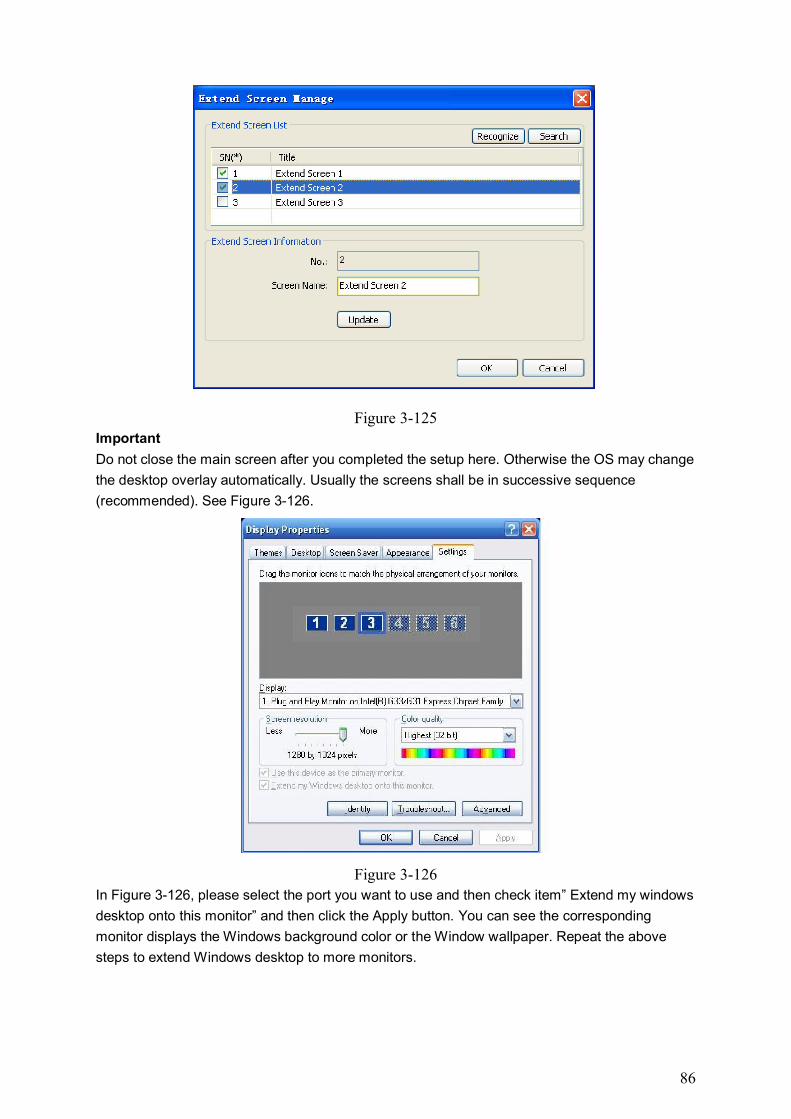
86
Figure 3-125 Important
Do not close the main screen after you completed the setup here. Otherwise the OS may change
the desktop overlay automatically. Usually the screens shall be in successive sequence
(recommended). See Figure 3-126.
Figure 3-126
In Figure 3-126, please select the port you want to use and then check item” Extend my windows
desktop onto this monitor” and then click the Apply button. You can see the corresponding
monitor displays the Windows background color or the Window wallpaper. Repeat the above
steps to extend Windows desktop to more monitors.
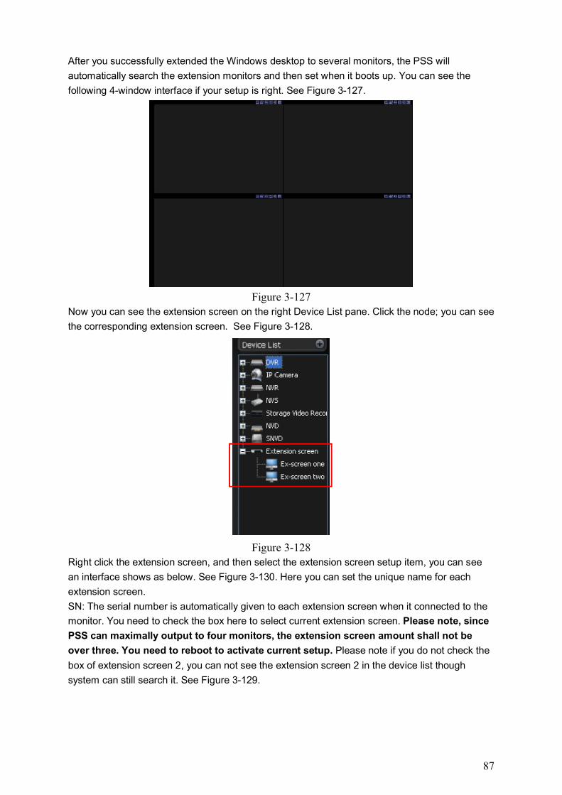
87
After you successfully extended the Windows desktop to several monitors, the PSS will
automatically search the extension monitors and then set when it boots up. You can see the
following 4-window interface if your setup is right. See Figure 3-127.
Figure 3-127
Now you can see the extension screen on the right Device List pane. Click the node; you can see
the corresponding extension screen. See Figure 3-128.
Figure 3-128
Right click the extension screen, and then select the extension screen setup item, you can see
an interface shows as below. See Figure 3-130. Here you can set the unique name for each
extension screen.
SN: The serial number is automatically given to each extension screen when it connected to the
monitor. You need to check the box here to select current extension screen. Please note, since
PSS can maximally output to four monitors, the extension screen amount shall not be
over three. You need to reboot to activate current setup. Please note if you do not check the
box of extension screen 2, you can not see the extension screen 2 in the device list though
system can still search it. See Figure 3-129.
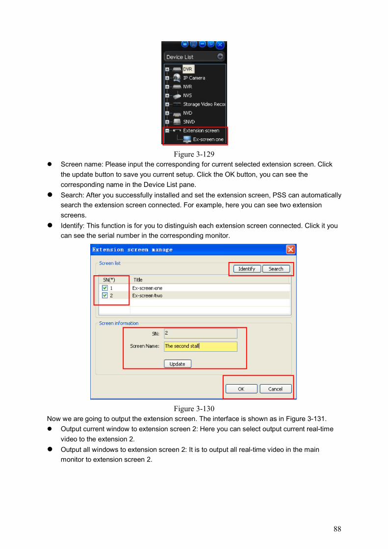
88
Figure 3-129
Screen name: Please input the corresponding for current selected extension screen. Click
the update button to save you current setup. Click the OK button, you can see the
corresponding name in the Device List pane.
Search: After you successfully installed and set the extension screen, PSS can automatically
search the extension screen connected. For example, here you can see two extension
screens.
Identify: This function is for you to distinguish each extension screen connected. Click it you
can see the serial number in the corresponding monitor.
Figure 3-130
Now we are going to output the extension screen. The interface is shown as in Figure 3-131.
Output current window to extension screen 2: Here you can select output current real-time
video to the extension 2.
Output all windows to extension screen 2: It is to output all real-time video in the main
monitor to extension screen 2.
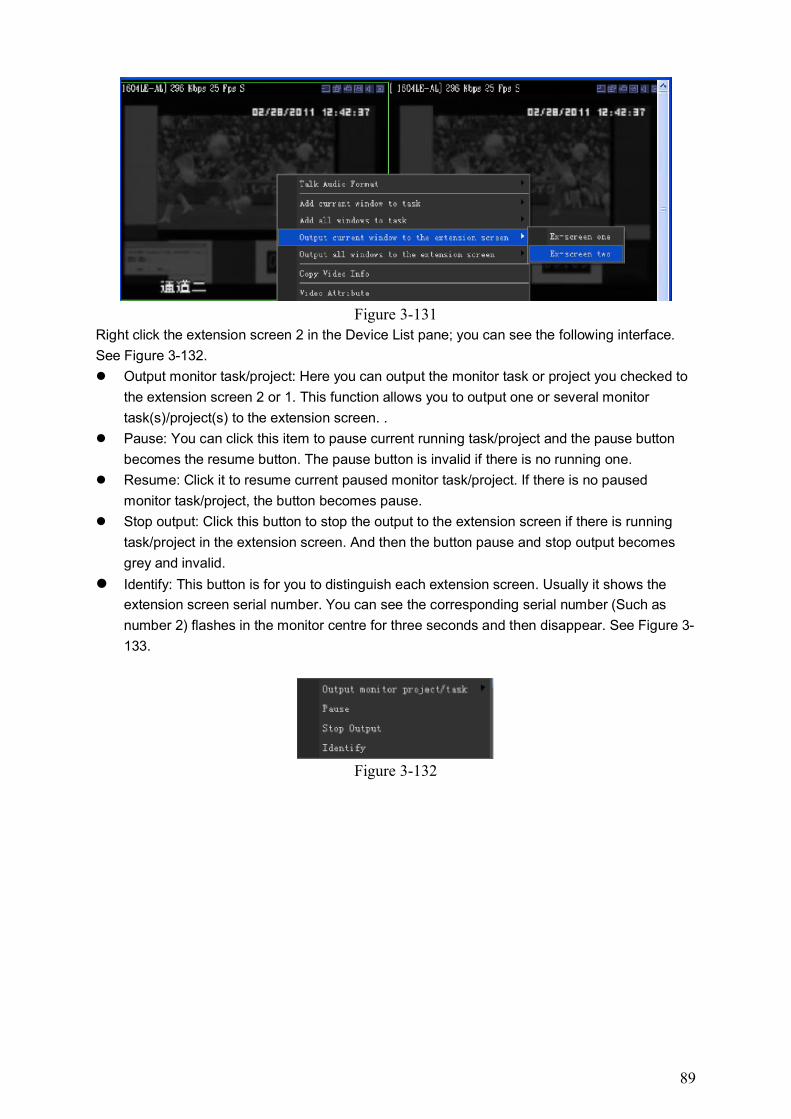
89
Figure 3-131
Right click the extension screen 2 in the Device List pane; you can see the following interface.
See Figure 3-132.
Output monitor task/project: Here you can output the monitor task or project you checked to
the extension screen 2 or 1. This function allows you to output one or several monitor
task(s)/project(s) to the extension screen. .
Pause: You can click this item to pause current running task/project and the pause button
becomes the resume button. The pause button is invalid if there is no running one.
Resume: Click it to resume current paused monitor task/project. If there is no paused
monitor task/project, the button becomes pause.
Stop output: Click this button to stop the output to the extension screen if there is running
task/project in the extension screen. And then the button pause and stop output becomes
grey and invalid.
Identify: This button is for you to distinguish each extension screen. Usually it shows the
extension screen serial number. You can see the corresponding serial number (Such as
number 2) flashes in the monitor centre for three seconds and then disappear. See Figure 3-
133.
Figure 3-132
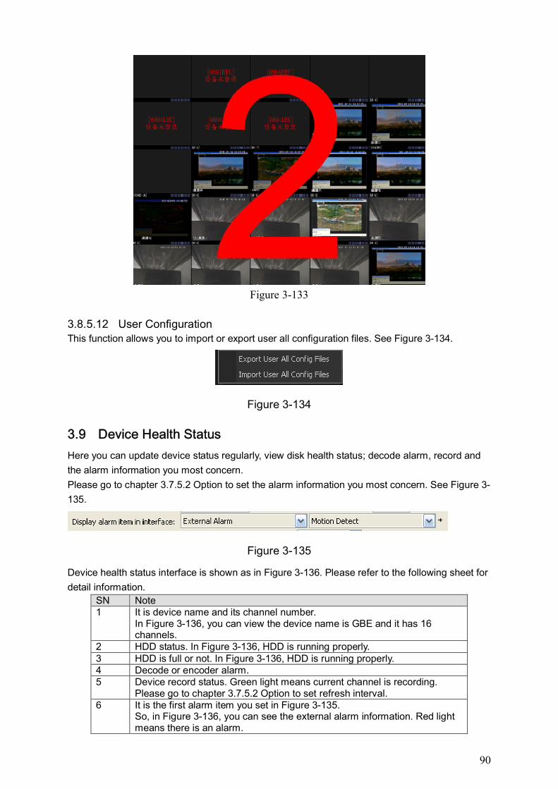
90
Figure 3-133
3.8.5.12 User Configuration This function allows you to import or export user all configuration files. See Figure 3-134.
Figure 3-134
3.9 Device Health Status
Here you can update device status regularly, view disk health status; decode alarm, record and
the alarm information you most concern.
Please go to chapter 3.7.5.2 Option to set the alarm information you most concern. See Figure 3-
135.
Figure 3-135
Device health status interface is shown as in Figure 3-136. Please refer to the following sheet for
detail information.
SN Note 1 It is device name and its channel number.
In Figure 3-136, you can view the device name is GBE and it has 16 channels.
2 HDD status. In Figure 3-136, HDD is running properly. 3 HDD is full or not. In Figure 3-136, HDD is running properly. 4 Decode or encoder alarm. 5 Device record status. Green light means current channel is recording.
Please go to chapter 3.7.5.2 Option to set refresh interval. 6 It is the first alarm item you set in Figure 3-135.
So, in Figure 3-136, you can see the external alarm information. Red light means there is an alarm.
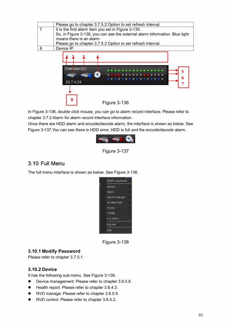
91
Please go to chapter 3.7.5.2 Option to set refresh interval. 7 It is the first alarm item you set in Figure 3-135.
So, in Figure 3-136, you can see the external alarm information. Blue light means there is an alarm. Please go to chapter 3.7.5.2 Option to set refresh interval.
8 Device IP.
Figure 3-136
In Figure 3-136, double click mouse, you can go to alarm record interface. Please refer to
chapter 3.7.2 Alarm for alarm record interface information.
Once there are HDD alarm and encode/decode alarm, the interface is shown as below. See
Figure 3-137.You can see there is HDD error, HDD is full and the encode/decode alarm.
Figure 3-137
3.10 Full Menu
The full menu interface is shown as below. See Figure 3-138.
Figure 3-138
3.10.1 Modify Password Please refer to chapter 3.7.5.1.
3.10.2 Device It has the following sub-menu. See Figure 3-139.
Device management: Please refer to chapter 3.8.5.8.
Health report: Please refer to chapter 3.8.4.3.
NVD manage: Please refer to chapter 3.8.5.9.
NVD control: Please refer to chapter 3.8.4.2.
1 2 3 4
5
6
7
8
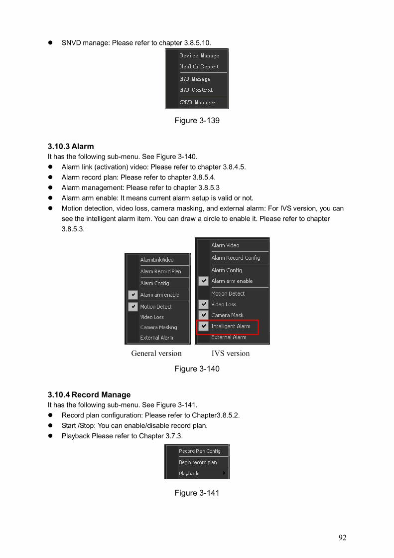
92
SNVD manage: Please refer to chapter 3.8.5.10.
Figure 3-139
3.10.3 Alarm It has the following sub-menu. See Figure 3-140.
Alarm link (activation) video: Please refer to chapter 3.8.4.5.
Alarm record plan: Please refer to chapter 3.8.5.4.
Alarm management: Please refer to chapter 3.8.5.3
Alarm arm enable: It means current alarm setup is valid or not.
Motion detection, video loss, camera masking, and external alarm: For IVS version, you can
see the intelligent alarm item. You can draw a circle to enable it. Please refer to chapter
3.8.5.3.
General version IVS version
Figure 3-140
3.10.4 Record Manage It has the following sub-menu. See Figure 3-141.
Record plan configuration: Please refer to Chapter3.8.5.2.
Start /Stop: You can enable/disable record plan.
Playback Please refer to Chapter 3.7.3.
Figure 3-141
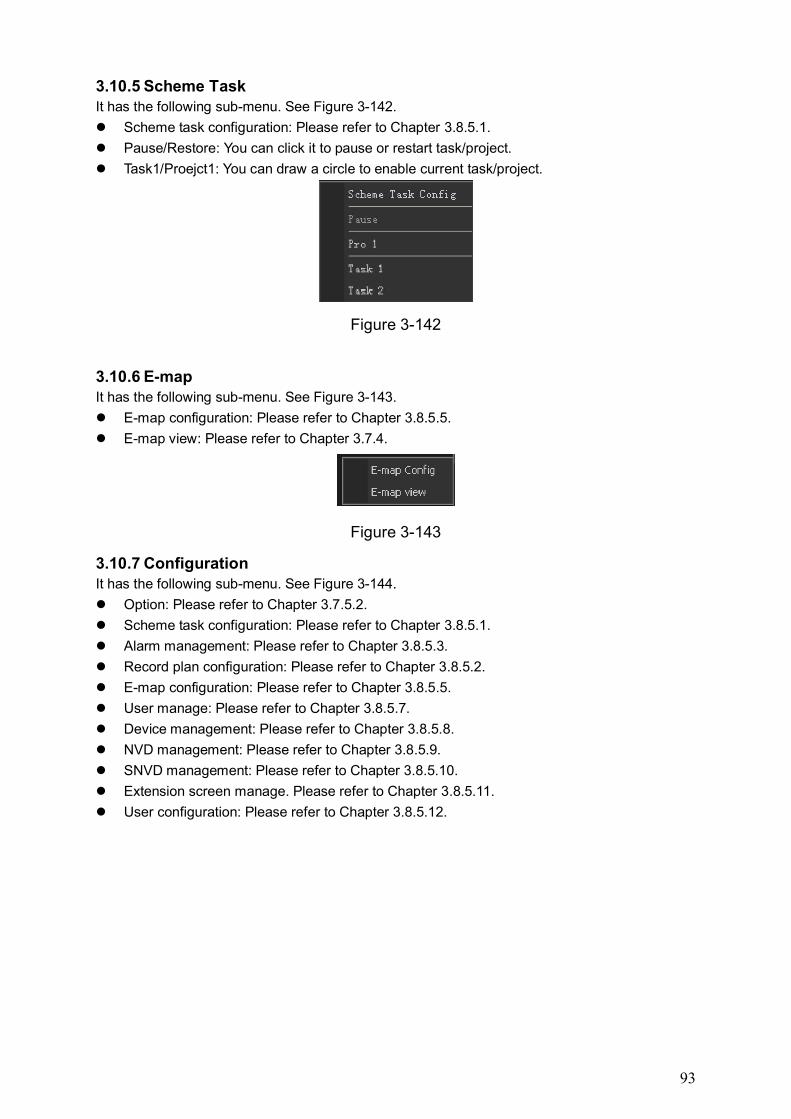
93
3.10.5 Scheme Task It has the following sub-menu. See Figure 3-142.
Scheme task configuration: Please refer to Chapter 3.8.5.1.
Pause/Restore: You can click it to pause or restart task/project.
Task1/Proejct1: You can draw a circle to enable current task/project.
Figure 3-142
3.10.6 E-map It has the following sub-menu. See Figure 3-143.
E-map configuration: Please refer to Chapter 3.8.5.5.
E-map view: Please refer to Chapter 3.7.4.
Figure 3-143
3.10.7 Configuration It has the following sub-menu. See Figure 3-144.
Option: Please refer to Chapter 3.7.5.2.
Scheme task configuration: Please refer to Chapter 3.8.5.1.
Alarm management: Please refer to Chapter 3.8.5.3.
Record plan configuration: Please refer to Chapter 3.8.5.2.
E-map configuration: Please refer to Chapter 3.8.5.5.
User manage: Please refer to Chapter 3.8.5.7.
Device management: Please refer to Chapter 3.8.5.8.
NVD management: Please refer to Chapter 3.8.5.9.
SNVD management: Please refer to Chapter 3.8.5.10.
Extension screen manage. Please refer to Chapter 3.8.5.11.
User configuration: Please refer to Chapter 3.8.5.12.
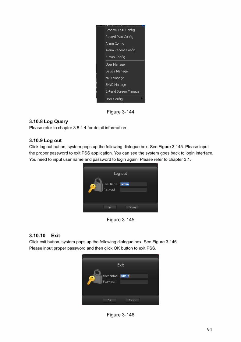
94
Figure 3-144
3.10.8 Log Query Please refer to chapter 3.8.4.4 for detail information.
3.10.9 Log out Click log out button, system pops up the following dialogue box. See Figure 3-145. Please input
the proper password to exit PSS application. You can see the system goes back to login interface.
You need to input user name and password to login again. Please refer to chapter 3.1.
Figure 3-145
3.10.10 Exit Click exit button, system pops up the following dialogue box. See Figure 3-146.
Please input proper password and then click OK button to exit PSS.
Figure 3-146
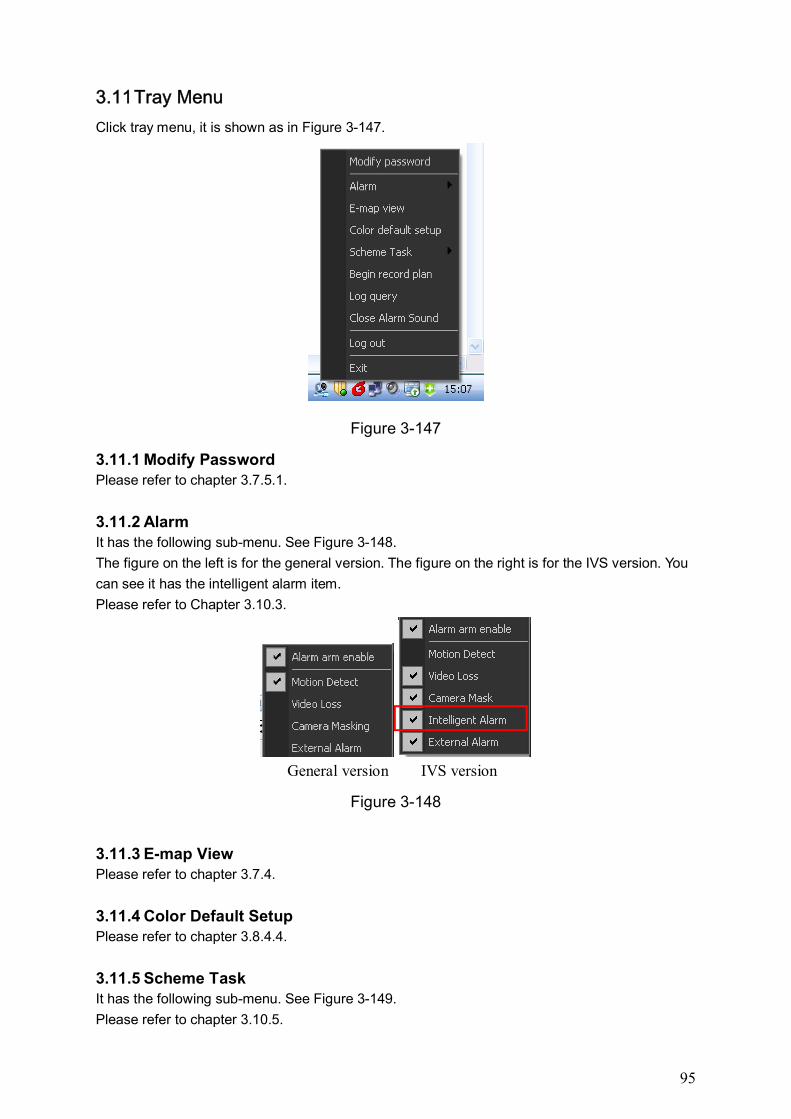
95
3.11 Tray Menu
Click tray menu, it is shown as in Figure 3-147.
Figure 3-147
3.11.1 Modify Password Please refer to chapter 3.7.5.1.
3.11.2 Alarm It has the following sub-menu. See Figure 3-148.
The figure on the left is for the general version. The figure on the right is for the IVS version. You
can see it has the intelligent alarm item.
Please refer to Chapter 3.10.3.
General version IVS version
Figure 3-148
3.11.3 E-map View Please refer to chapter 3.7.4.
3.11.4 Color Default Setup Please refer to chapter 3.8.4.4.
3.11.5 Scheme Task It has the following sub-menu. See Figure 3-149.
Please refer to chapter 3.10.5.
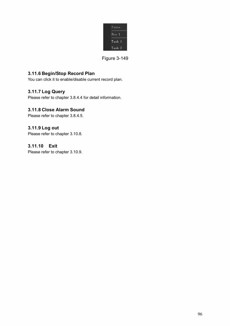
96
Figure 3-149
3.11.6 Begin/Stop Record Plan You can click it to enable/disable current record plan.
3.11.7 Log Query Please refer to chapter 3.8.4.4 for detail information.
3.11.8 Close Alarm Sound Please refer to chapter 3.8.4.5.
3.11.9 Log out Please refer to chapter 3.10.8.
3.11.10 Exit Please refer to chapter 3.10.9.
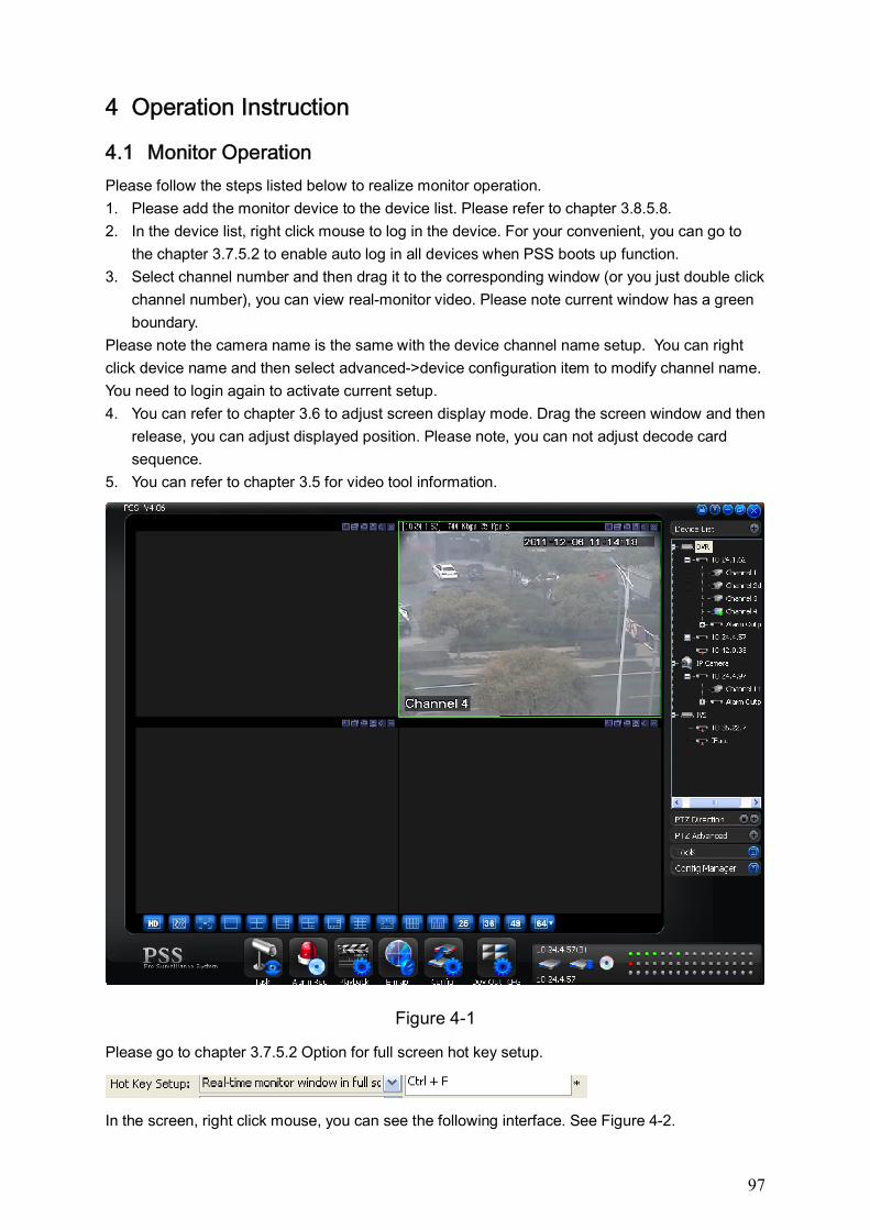
97
4 Operation Instruction
4.1 Monitor Operation
Please follow the steps listed below to realize monitor operation.
1. Please add the monitor device to the device list. Please refer to chapter 3.8.5.8.
2. In the device list, right click mouse to log in the device. For your convenient, you can go to
the chapter 3.7.5.2 to enable auto log in all devices when PSS boots up function.
3. Select channel number and then drag it to the corresponding window (or you just double click
channel number), you can view real-monitor video. Please note current window has a green
boundary.
Please note the camera name is the same with the device channel name setup. You can right
click device name and then select advanced->device configuration item to modify channel name.
You need to login again to activate current setup.
4. You can refer to chapter 3.6 to adjust screen display mode. Drag the screen window and then
release, you can adjust displayed position. Please note, you can not adjust decode card
sequence.
5. You can refer to chapter 3.5 for video tool information.
Figure 4-1
Please go to chapter 3.7.5.2 Option for full screen hot key setup.
In the screen, right click mouse, you can see the following interface. See Figure 4-2.
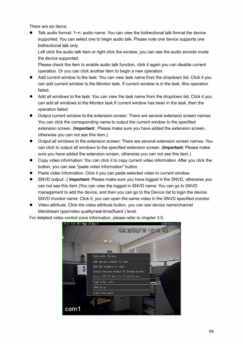
98
There are six items:
Talk audio format: 1~n: audio name. You can view the bidirectional talk format the device
supported. You can select one to begin audio talk. Please note one device supports one
bidirectional talk only.
Left click the audio talk item or right click the window, you can see the audio encode mode
the device supported.
Please check the item to enable audio talk function, click it again you can disable current
operation. Or you can click another item to begin a new operation.
Add current window to the task: You can view task name from the dropdown list. Click it you
can add current window to the Monitor task. If current window is in the task, tthe operation
failed.
Add all windows to the task: You can view the task name from the dropdown list. Click it you
can add all windows to the Monitor task.If current window has been in the task, then the
operation failed.
Output current window to the extension screen: There are several extension screen names.
You can click the corresponding name to output the current window to the specified
extension screen. (Important:: Please make sure you have added the extension screen,
otherwise you can not see this item.)
Output all windows to the extension screen: There are several extension screen names. You
can click to output all windows to the specified extension screen. (Important: Please make
sure you have added the extension screen, otherwise you can not see this item.)
Copy video information: You can click it to copy current video information. After you click the
button, you can see "paste video information" button.
Paste video information: Click it you can paste selected video to current window.
SNVD output: :( Important: Please make sure you have logged in the SNVD, otherwise you
can not see this item.)You can view the logged in SNVD name: You can go to SNVD
management to add the device, and then you can go to the Device list to login the device.
SNVD monitor name: Click it, you can open the same video in the SNVD specified monitor.
Video attribute: Click the video attribute button, you can see device name/channel
title/stream type/video quality/real-time(fluent ) level.
For detailed video control zone information, please refer to chapter 3.5.
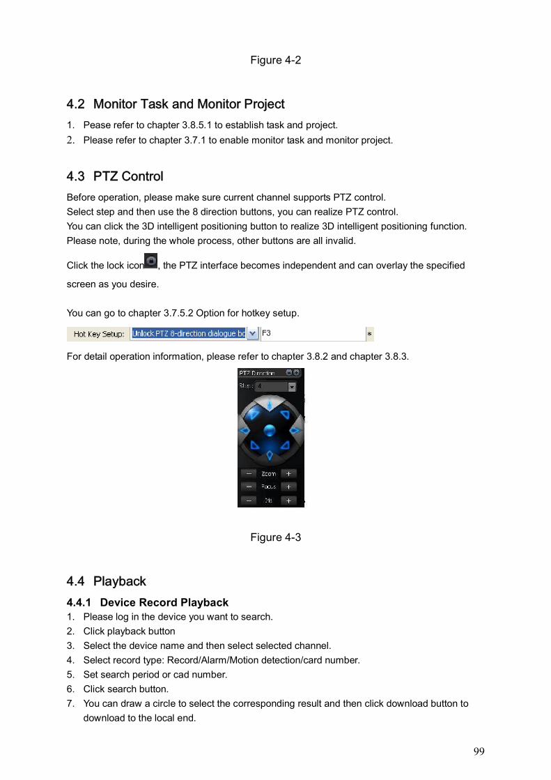
99
Figure 4-2
4.2 Monitor Task and Monitor Project
1. Pease refer to chapter 3.8.5.1 to establish task and project.
2. Please refer to chapter 3.7.1 to enable monitor task and monitor project.
4.3 PTZ Control
Before operation, please make sure current channel supports PTZ control.
Select step and then use the 8 direction buttons, you can realize PTZ control.
You can click the 3D intelligent positioning button to realize 3D intelligent positioning function.
Please note, during the whole process, other buttons are all invalid.
Click the lock icon , the PTZ interface becomes independent and can overlay the specified
screen as you desire.
You can go to chapter 3.7.5.2 Option for hotkey setup.
For detail operation information, please refer to chapter 3.8.2 and chapter 3.8.3.
Figure 4-3
4.4 Playback
4.4.1 Device Record Playback 1. Please log in the device you want to search.
2. Click playback button
3. Select the device name and then select selected channel.
4. Select record type: Record/Alarm/Motion detection/card number.
5. Set search period or cad number.
6. Click search button.
7. You can draw a circle to select the corresponding result and then click download button to
download to the local end.
100
8. Select one video window and then double click search result, you can playback the record.
4.4.2 Local Record Playback 1. Click playback button.
2. Select local record
3. Select the device name (if you want to search all devices, you can select unknown.). Then
you can select channel number.
4. Select the record type: Record/Alarm/Card number and others.
5. Set search period or cad number.
6. Click search button.
7. In the searched results, click remove button you can delete local record. Select one video
window and then double click search result, you can playback the record.
4.4.3 Download Select the file(s) you want to download and then click download button.
During the download process, you can click cancel button to terminate current operation.
The download files information is automatically added to the local record. You can search from
the local record.
Please note, the download process will pause if current channel is playback device record/ The
download resume after playback completes.
4.4.4 Record Play Control System maximally supports 4-ch playback.
Please refer to chapter 3.7.3 for playback information.
Double click video window you can adjust display mode.
You can enable snapshot function during playback.
4.4.5 Others Please refer to chapter 3.7.3 for playback information.
Record playback can download the specified record to the local end.
The download files information is automatically added to the local record. You can search from
the local record.
4.5 Snapshot and Manual Record
In real-time monitor or playback mode, you can enable snapshot or manual record function.
Please click snapshot to save current image to specified path.
You can click manual record button to enable recode function. Click it again, you can stop
manual record.
The snapshot file or manual recorded file is automatically added to the local record. You can
search to playback.
4.6 E-map
Please go to chapter 3.8.5.5 to establish E-map.
Please go to chapter 3.7.4 to view the detail e-map information.

101
E-map window can be displayed independently.
Double click the camera name in the E-map; you can enable real-time monitor function in the
video window.
When alarm occurs, corresponding node becomes flashing.
4.7 Log out
Please refer to chapter 3.10.8 or chapter 3.11.9 for log out information.
Click log out button, the interface is shown as below. See Figure 4-4. You need to input the
proper password and then click OK button to logout the PSS.
Figure 4-4
Now you can see system goes back to log in interface. See Figure 4-5. Current operation and
configuration all stopped. You need to input user name and password to log in. The record plan,
task and project, shortcut key, and right information are all for logged in user.
Figure 4-5
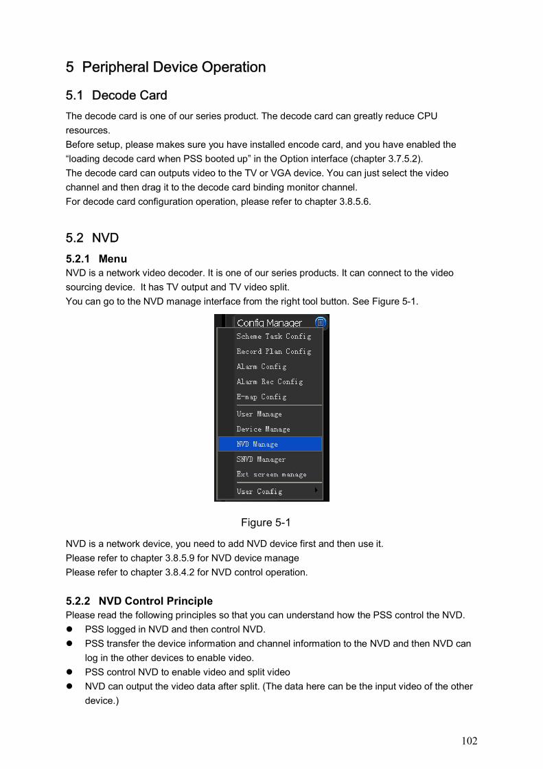
102
5 Peripheral Device Operation
5.1 Decode Card
The decode card is one of our series product. The decode card can greatly reduce CPU
resources.
Before setup, please makes sure you have installed encode card, and you have enabled the
“loading decode card when PSS booted up” in the Option interface (chapter 3.7.5.2).
The decode card can outputs video to the TV or VGA device. You can just select the video
channel and then drag it to the decode card binding monitor channel.
For decode card configuration operation, please refer to chapter 3.8.5.6.
5.2 NVD
5.2.1 Menu NVD is a network video decoder. It is one of our series products. It can connect to the video
sourcing device. It has TV output and TV video split.
You can go to the NVD manage interface from the right tool button. See Figure 5-1.
Figure 5-1
NVD is a network device, you need to add NVD device first and then use it.
Please refer to chapter 3.8.5.9 for NVD device manage
Please refer to chapter 3.8.4.2 for NVD control operation.
5.2.2 NVD Control Principle Please read the following principles so that you can understand how the PSS control the NVD.
PSS logged in NVD and then control NVD.
PSS transfer the device information and channel information to the NVD and then NVD can
log in the other devices to enable video.
PSS control NVD to enable video and split video
NVD can output the video data after split. (The data here can be the input video of the other
device.)
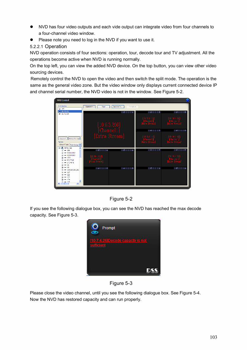
103
NVD has four video outputs and each vide output can integrate video from four channels to
a four-channel video window.
Please note you need to log in the NVD if you want to use it.
5.2.2.1 Operation NVD operation consists of four sections: operation, tour, decode tour and TV adjustment. All the
operations become active when NVD is running normally.
On the top left, you can view the added NVD device. On the top button, you can view other video
sourcing devices.
Remotely control the NVD to open the video and then switch the split mode. The operation is the
same as the general video zone. But the video window only displays current connected device IP
and channel serial number, the NVD video is not in the window. See Figure 5-2.
Figure 5-2
If you see the following dialogue box, you can see the NVD has reached the max decode
capacity. See Figure 5-3.
Figure 5-3
Please close the video channel, until you see the following dialogue box. See Figure 5-4.
Now the NVD has restored capacity and can run properly.
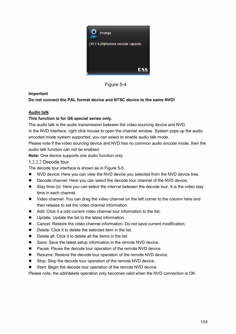
104
Figure 5-4
Important
Do not connect the PAL format device and NTSC device to the same NVD!
Audio talk
This function is for G6 special series only.
The audio talk is the audio transmission between the video sourcing device and NVD.
In the NVD interface, right click mouse to open the channel window. System pops up the audio
encoded mode system supported, you can select to enable audio talk mode.
Please note if the video sourcing device and NVD has no common audio encode mode, then the
audio talk function can not be enabled.
Note: One device supports one audio function only.
5.2.2.2 Decode tour The decode tour interface is shown as in Figure 5-5.
NVD device: Here you can view the NVD device you selected from the NVD device tree.
Decode channel: Here you can select the decode tour channel of the NVD device.
Stay time (s): Here you can select the interval between the decode tour. It is the video stay
time in each channel.
Video channel: You can drag the video channel on the left corner to the column here and
then release to set the video channel information.
Add: Click it a odd current video channel tour information to the list.
Update: Update the list to the latest information.
Cancel: Restore the video channel information. Do not save current modification.
Delete: Click it to delete the selected item in the list.
Delete all: Click it to delete all the items in the list.
Save: Save the latest setup information in the remote NVD device.
Pause: Pause the decode tour operation of the remote NVD device.
Resume: Restore the decode tour operation of the remote NVD device.
Stop: Stop the decode tour operation of the remote NVD device.
Start: Begin the decode tour operation of the remote NVD device.
Please note, the add/delete operation only becomes valid when the NVD connection is OK.
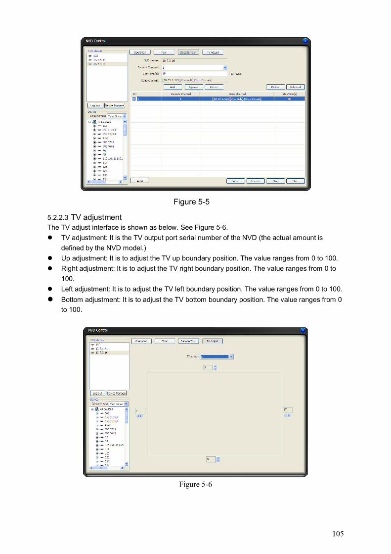
105
Figure 5-5
5.2.2.3 TV adjustment The TV adjust interface is shown as below. See Figure 5-6.
TV adjustment: It is the TV output port serial number of the NVD (the actual amount is
defined by the NVD model.)
Up adjustment: It is to adjust the TV up boundary position. The value ranges from 0 to 100.
Right adjustment: It is to adjust the TV right boundary position. The value ranges from 0 to
100.
Left adjustment: It is to adjust the TV left boundary position. The value ranges from 0 to 100.
Bottom adjustment: It is to adjust the TV bottom boundary position. The value ranges from 0
to 100.
Figure 5-6

106
Note:
This user’s manual is for reference only. Slight difference may be found in the user
interface.
All the designs and software here are subject to change without prior written notice.
If there is any uncertainty or controversy, please refer to the final explanation of us.
Please visit our website for more information.