Embed Size (px)
Citation preview
Ring ClearancesWhile dimensionally stable in the presence of liquids, CPI filled PTFE materials can be affected by thermal expansion. Provision has been made in sizing the ring gap and side clearance, which may make the rings appear to have 3-8 times greater clearances than metal rings when installed at room temperature. However, at operating temperatures the clearances will be similar to metal rings.
LubricationCPI filled PTFE materials are unique because they can operate completely dry — without lubrication — at differential pressures of up to 725 psi (50 bar); or they can be run with lubrication — although with substantially less than the amount of oil required for metal parts at pressures up to 1450 psi (100 bar). CPI filled PTFE materials are not adversely affected by synthetic lubricants.
Caution Intermittent LubricationWhile CPI filled PTFE materials will operate either dry or with lubrication, they should not be operated under conditions of intermittent oil supply. This usually results in high ring wear, which is evident by a black, greasy residue. If this occurs, the parts should be thoroughly cleaned and steps taken to ensure steady lubrication.
DirtThe matrix of CPI filled PTFE is relatively soft and can assimilate small amounts of dirt without damage. However, large quantities of foreign material can cause wear of the cylinder and/or rings.
Cylinder If the cylinder has been re-machined, care must be taken to clean all debris from the cylinder bore and ports. In oil free service, CPI filled PTFE replacements do not require removal of PTFE film.
Wiping the cylinder and piston to remove debris is sufficient. Heavy deposits of PTFE on the cylinder must be removed and are generally caused by overheating. Cylinder cooling jackets should be checked for blockage or deposits, which can impede heat transfer. In lubricated service, the cylinder should be cleaned to remove dirt and wear debris. Carbon, gum and lacquer deposits from decomposed lubricant should also be removed. Such deposits can cause ring wear and sticking, and they impede heat transfer to the cooling jacket.
PistonRing grooves should be straight and perpendicular to the piston axis. If re-cutting is necessary, the actual groove should be supplied to ensure correct new ring sizing.
Piston and Rider Rings
COMPRESSORPRODUCTS INTL
Proven Solutions for the Global Compression Industry™
™
COMPRESSORPRODUCTS INTL
Proven Solutions for the Global Compression Industry
an EnPro Industries company
an EnPro Industries company
an EnPro Industries company
an EnPro Industries company
The unique properties of CPI polytetrafluroethylene (PTFE) materials make them particularly suited for sealing and bearing rings in reciprocating compressor cylinders. If you have not previously installed or used CPI filled PTFE piston and rider rings there are characteristics to consider.
2
HOW TO INSTALL CPI PACKINGS
3
COMPRESSORPRODUCTS INTL
Proven Solutions for the Global Compression Industry™
™
COMPRESSORPRODUCTS INTL
Proven Solutions for the Global Compression Industry
an EnPro Industries company
an EnPro Industries company
an EnPro Industries company
an EnPro Industries company
evolving solutions around your worldevolving solutions around your world
evolving solutions around your world
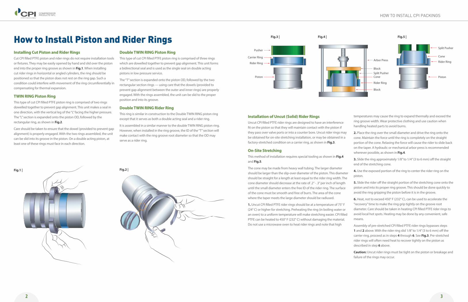
Installing Cut Piston and Rider RingsCut CPI filled PTFE piston and rider rings do not require installation tools or fixtures. They may be easily opened by hand and slid over the piston end into the proper ring groove as shown in Fig.1. When installing cut rider rings in horizontal or angled cylinders, the ring should be positioned so that the piston does not rest on the ring gap. Such a condition could interfere with movement of the ring circumferentially in compensating for thermal expansion.
TWIN RING Piston RingThis type of cut CPI filled PTFE piston ring is comprised of two rings dowelled together to prevent gap alignment. This unit makes a seal in one direction, with the vertical leg of the “L” facing the higher pressure. The “L” section is expanded onto the piston OD, followed by the rectangular ring, as shown in Fig.2.
Care should be taken to ensure that the dowel (provided to prevent gap alignment) is properly engaged. With the two rings assembled, the unit can be slid into its groove in the piston. On a double acting piston, at least one of these rings must face in each direction.
Double TWIN RING Piston RingThis type of cut CPI filled PTFE piston ring is comprised of three rings which are dowelled together to prevent gap alignment. This unit forms a bidirectional seal and is used as the single seal on double acting pistons in low pressure service.
The “T” section is expanded onto the piston OD, followed by the two rectangular section rings — using care that the dowels (provided to prevent gap alignment between the outer and inner rings) are properly engaged. With the rings assembled, the unit can be slid to the proper position and into its groove.
Double TWIN RING Rider RingThis ring is similar in construction to the Double TWIN RING piston ring except that it serves as both a double acting seal and a rider ring.
It is assembled in a similar manner to the double TWIN RING piston ring. However, when installed in the ring groove, the ID of the “T” section will make contact with the ring groove root diameter so that the OD may serve as a rider ring.
Installation of Uncut (Solid) Rider RingsUncut CPI filled PTFE rider rings are designed to have an interference fit on the piston so that they will maintain contact with the piston if they pass over valve ports or into a counter bore. Uncut rider rings may be obtained for on-site stretching installation, or may be obtained in a factory-stretched condition on a carrier ring, as shown in Fig.3.
On-Site StretchingThis method of installation requires special tooling as shown in Fig.4 and Fig.5.
The cone may be made from heavy wall tubing. The larger diameter should be larger than the slip-over diameter of the piston. This diameter should be straight for a length at least equal to the rider ring width. The cone diameter should decrease at the rate of .2” - .3” per inch of length until the small diameter enters the free ID of the rider ring. The surface of the cone must be smooth and free of burrs. The area of the cone where the taper meets the large diameter should be radiused.
1. Uncut CPI filled PTFE rider rings should be at a temperature of 75° F (24° C) or higher for stretching. Preheating the ring (in boiling water or an oven) to a uniform temperature will make stretching easier. CPI filled PTFE can be heated to 450° F (232° C) without damaging the material. Do not use a microwave oven to heat rider rings and note that high
temperatures may cause the ring to expand thermally and exceed the ring groove width. Wear protective clothing and use caution when handling heated parts to avoid burns.
2. Place the ring over the small diameter and drive the ring onto the cone. Maintain the force until the ring is completely on the straight portion of the cone. Relaxing the force will cause the rider to slide back on the taper. A hydraulic or mechanical arbor press is recommended wherever possible, as shown in Fig.4.
3. Slide the ring approximately 1/8” to 1/4” (3 to 6 mm) off the straight end of the stretching cone.
4. Use the exposed portion of the ring to center the rider ring on the piston.
5. Slide the rider off the straight portion of the stretching cone onto the piston and into its proper ring groove. This should be done quickly to avoid the ring gripping the piston before it is in the groove.
6. Heat, not to exceed 450° F (232° C), can be used to accelerate the “recovery” time to make the ring grip tightly on the groove root diameter. Care should be taken in heating CPI filled PTFE rider rings to avoid local hot spots. Heating may be done by any convenient, safe means.
Assembly of pre-stretched CPI filled PTFE rider rings bypasses steps 1 and 2 above. With the rider ring slid 1/8” to 1/4” (3 to 6 mm) off the carrier ring, proceed as in steps 4 through 6. See Fig.3. Pre-stretched rider rings will often need heat to recover tightly on the piston as described in step 6 above.
Caution: Uncut rider rings must be tight on the piston or breakage and failure of the rings may occur.
How to Install Piston and Rider Rings
Fig.1 |
Fig.3 | Fig.4 | Fig.5 |
Fig.2 |
Pusher
Arbor Press
Split Pusher
Cone
Rider Ring
Piston
BlockSplit PusherCone
Rider Ring
Block
Carrier Ring
Rider Ring
Piston
COMPRESSORPRODUCTS INTL
Proven Solutions for the Global Compression Industry™
™
COMPRESSORPRODUCTS INTL
Proven Solutions for the Global Compression Industry
an EnPro Industries company
an EnPro Industries company
an EnPro Industries company
an EnPro Industries company
© 2015 CPI. All rights reserved.
4
COMPRESSORPRODUCTS INTL
Proven Solutions for the Global Compression Industry™
™
COMPRESSORPRODUCTS INTL
Proven Solutions for the Global Compression Industry
an EnPro Industries company
an EnPro Industries company
an EnPro Industries company
an EnPro Industries company
www.CPIcompression.comPISTONRIDER.ENG.1506.LTR
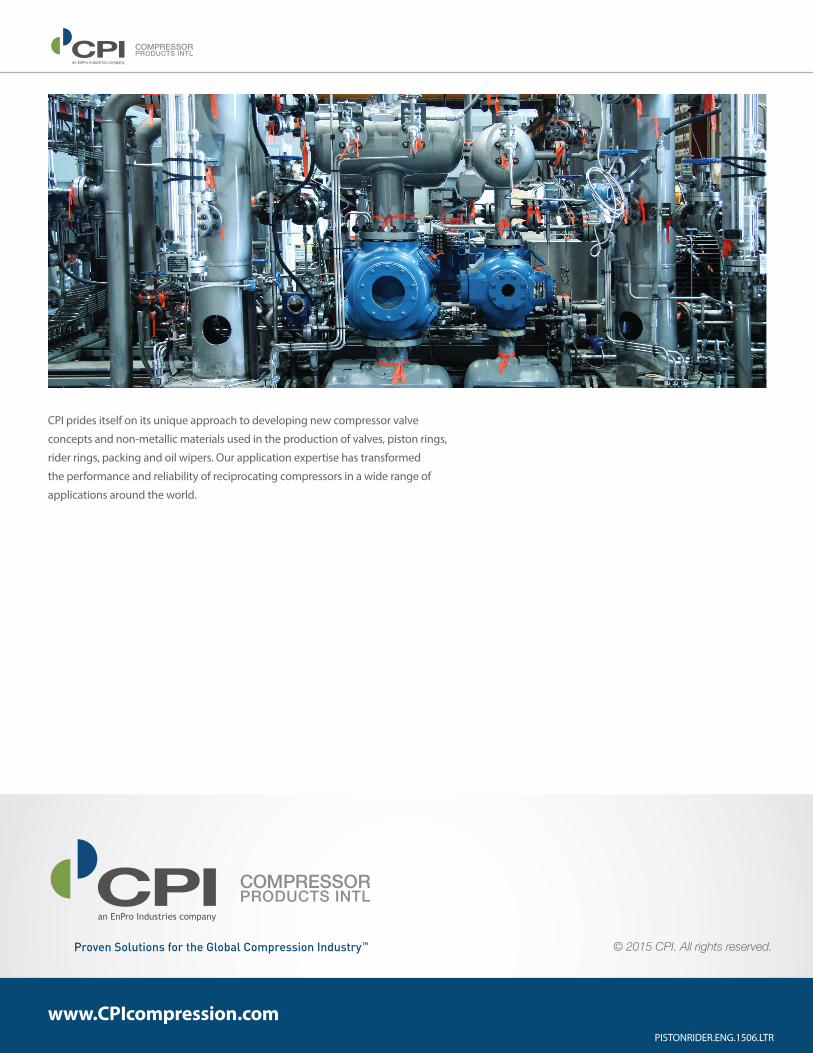
CPI prides itself on its unique approach to developing new compressor valve
concepts and non-metallic materials used in the production of valves, piston rings,
rider rings, packing and oil wipers. Our application expertise has transformed
the performance and reliability of reciprocating compressors in a wide range of
applications around the world.