Embed Size (px)
Citation preview
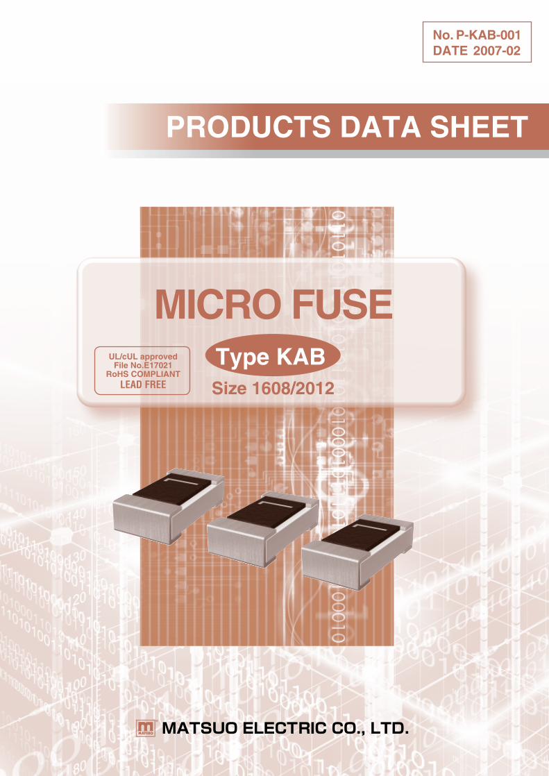
PRODUCTS DATA SHEET
No. P-KAB-001DATE 2007-02
Type KAB
MICRO FUSEUL/cUL approved
File No.E17021RoHS COMPLIANT
LEAD FREE Size 1608/2012
-2-
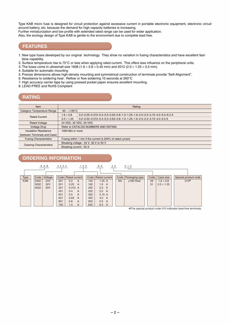
Type KAB micro fuse is designed for circuit protection against excessive current in portable electronic equipment, electronic circuit around battery, etc. because the demand for high capacity batteries is increasing.Further miniaturization and low profile with extended rated range can be used for wider application.Also, the ecology design of Type KAB is gentle to the environment due to complete lead free.
1. New type fuses developed by our original technology. They show no variation in fusing characteristics and have excellent fast-blow capability.
2. Surface temperature rise is 75°C or less when applying rated current. This offers less influence on the peripheral units.3. The fuses come in ultrasmall size 1608 (1.6 × 0.8 × 0.45 mm) and 2012 (2.0 × 1.25 × 0.5 mm). 4. Suitable for automatic mounting5. Precise dimensions allows high-density mounting and symmetrical construction of terminals provide “Self-Alignment”.6. Resistance to soldering heat : Reflow or flow soldering 10 seconds at 260°C7. High accuracy carrier tape by using pressed pocket paper ensures excellent mounting.8. LEAD-FREE and RoHS Compliant
Item Rating
Category Temperature Range
Rated Current
Rated Voltage
Voltage Drop
Insulation Resistance
(between Terminals and Case)
Fusing Characteristics
Clearing Characteristics
-40 ~ +125°C1.6 × 0.8 0.2–0.25–0.315–0.4–0.5–0.63–0.8–1.0–1.25–1.6–2.0–2.5–3.15–4.0–5.0–6.3 A
2.0 × 1.25 0.2–0.25–0.315–0.4–0.5–0.63–0.8–1.0–1.25–1.6–2.0–2.5–3.15–4.0–5.0 A
24 VDC, 32 VDC, 50 VDC
Refer to CATALOG NUMBERS AND RATING
1000 MΩ or more
Fusing within 1 min if the current is 200% of rated current.
Breaking voltage : 24 V, 32 V or 50 V
Breaking current : 50 A
K A B 3 2 0 2 1 0 2 N A 2 9 0 1 0
TypeKAB
Code240232025002
Code201251321401501631801102
Rated current0.2 A0.25 A0.315 A0.4 A0.5 A0.63 A0.8 A1.0 A
Code132162202252322402502632
Rated current1.25 A1.6 A2.0 A2.5 A3.15 A4.0 A5.0 A6.3 A
CodeNA
Packaging typef180 Reel
Code Case size Special product code2931
1.6 × 0.82.0 × 1.25
010
Voltage24V32V50V
The special product code 010 indicates lead-free terminals.
FEATURES
RATING
ORDERING INFORMATION
-3-
Code : Rated current Code : Rated current0.20.250.3150.40.50.630.81.0
PQRSTUV1
::::::::
::::::::
WX2Y3456
1.251.62.02.53.154.05.06.3
AAAAAAAA
AAAAAAAA
Protective coatingTerminal
Body
Fuse element
1
P
P
P
PL W
T
Size 1608 Size 2012
a 1.4
b 1.65
c 1.2
1.0
1.2
1.0
Size a
1.2
1.5
a ac
b
100 mm
33 mm5 mm
a mm
Glass epoxy on one sideBoard thickness : 1.6 mmCopper layer : 35 µm
(mm)
(mm)
Case size
1608
2012
Catalog number
KAB 2402 201 31 010
KAB 2402 251 31 010
KAB 2402 321 31 010
KAB 2402 401 31 010
KAB 2402 501 31 010
KAB 2402 631 31 010
KAB 2402 801 31 010
KAB 2402 102 31 010
KAB 2402 132 31 010
KAB 2402 162 31 010
KAB 2402 202 31 010
KAB 2402 252 31 010
KAB 2402 322 31 010
KAB 2402 402 31 010
KAB 2402 502 31 010
0.2
0.25
0.315
0.4
0.5
0.63
0.8
1.0
1.25
1.6
2.0
2.5
3.15
4.0
5.0
1740
1280
800
440
260
175
120
90
67
48
36
28
21
16
10
480
475
375
255
170
150
145
135
130
120
115
110
105
95
60
KAB 5002 201 29 010
KAB 5002 251 29 010
KAB 5002 321 29 010
KAB 5002 401 29 010
KAB 5002 501 29 010
KAB 3202 631 29 010
KAB 3202 801 29 010
KAB 3202 102 29 010
KAB 3202 132 29 010
KAB 3202 162 29 010
KAB 3202 202 29 010
KAB 2402 252 29 010
KAB 2402 322 29 010
KAB 2402 402 29 010
KAB 2402 502 29 010
KAB 2402 632 29 010
0.2
0.25
0.315
0.4
0.5
0.63
0.8
1.0
1.25
1.6
2.0
2.5
3.15
4.0
5.0
6.3
1260
825
530
320
210
135
100
80
60
46
35
27
20
15
13
10
405
355
275
180
140
115
110
110
110
110
110
110
110
110
110
110
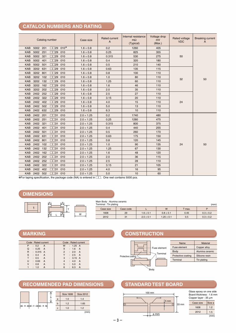
Rated currentA
Internal resistancemΩ
(Typical)
Voltage dropmV
(Max.)
Rated voltageVDC
Breaking currentA
Case size
50
32
24
50
For taping specification, the package code (NA) is entered in . One reel contains 5000 pcs.
24 50
CATALOG NUMBERS AND RATING
DIMENSIONS
MARKING
RECOMMENDED PAD DIMENSIONS
CONSTRUCTION
STANDARD TEST BOARD
Case size
1608
2012
Case code
29
31
L W T max.
1.6 ± 0.1
2.0 ± 0.1
0.8 ± 0.1
1.25 ± 0.1
0.45
0.5
P
0.3 ± 0.2
0.3 ± 0.2
(mm)Main Body : Alumina ceramicTerminal : Tin plating
2.0 × 1.25
2.0 × 1.25
2.0 × 1.25
2.0 × 1.25
2.0 × 1.25
2.0 × 1.25
2.0 × 1.25
2.0 × 1.25
2.0 × 1.25
2.0 × 1.25
2.0 × 1.25
2.0 × 1.25
2.0 × 1.25
2.0 × 1.25
2.0 × 1.25
1.6 × 0.8
1.6 × 0.8
1.6 × 0.8
1.6 × 0.8
1.6 × 0.8
1.6 × 0.8
1.6 × 0.8
1.6 × 0.8
1.6 × 0.8
1.6 × 0.8
1.6 × 0.8
1.6 × 0.8
1.6 × 0.8
1.6 × 0.8
1.6 × 0.8
1.6 × 0.8
Fuse element
Body
Protective coating
Terminal
Copper alloy
Alumina ceramic
Silicone resin
Tin plating
MaterialName
-4-
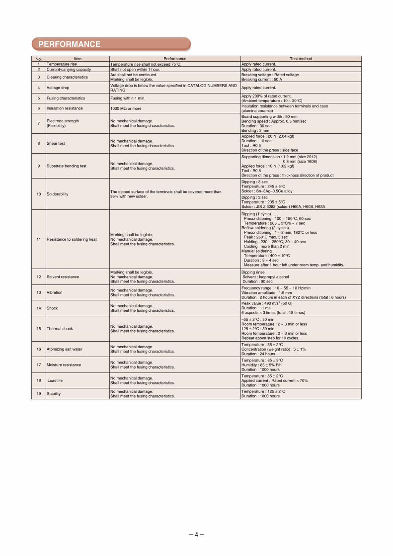
PERFORMANCE
No. Item Performance Test method
Voltage drop Voltage drop is below the value specified in CATALOG NUMBERS AND RATING.
Breaking voltage : Rated voltageBreaking current : 50 A
Dipping : 3 secTemperature : 235 ± 5°CSolder : JIS Z 3282 (solder) H60A, H60S, H63A
Dipping rinse Solvent : Isopropyl alcohol Duration : 90 sec
Dipping (1 cycle)Preconditioning : 100 ~ 150°C, 60 secTemperature : 265 ± 3°C/6 ~ 7 sec
Reflow soldering (2 cycles)Preconditioning : 1 ~ 2 min, 180°C or lessPeak : 260°C max, 5 secHolding : 230 ~ 250°C, 30 ~ 40 secCooling : more than 2 min
Manual solderingTemperature : 400 ± 10°CDuration : 3 ~ 4 secMeasure after 1 hour left under room temp. and humidity.
Dipping : 3 secTemperature : 245 ± 5°CSolder : Sn–3Ag–0.5Cu alloy
Temperature : 85 ± 3°CHumidity : 85 ± 5% RHDuration : 1000 hours
Temperature : 85 ± 2°CApplied current : Rated current × 70%Duration : 1000 hours
19 Stability Temperature : 125 ± 2°CDuration : 1000 hours
Temperature : 35 ± 2°CConcentration (weight ratio) : 5 ± 1%Duration : 24 hours
–55 ± 3°C : 30 minRoom temperature : 2 ~ 3 min or less125 ± 2°C : 30 minRoom temperature : 2 ~ 3 min or lessRepeat above step for 10 cycles.
Peak value : 490 m/s2 (50 G)Duration : 11 ms6 aspects × 3 times (total : 18 times)
Frequency range : 10 ~ 55 ~ 10 Hz/minVibration amplitude : 1.5 mm Duration : 2 hours in each of XYZ directions (total : 6 hours)
Marking shall be legible. No mechanical damage.Shall meet the fusing characteristics.
Supporting dimension : 1.2 mm (size 2012)0.8 mm (size 1608)
Applied force : 10 N (1.02 kgf)Tool : R0.5Direction of the press : thickness direction of product
Applied force : 20 N (2.04 kgf)Duration : 10 secTool : R0.5Direction of the press : side face
Board supporting width : 90 mmBending speed : Approx. 0.5 mm/secDuration : 30 secBending : 3 mm
6 Insulation resistance 1000 MΩ or moreInsulation resistance between terminals and case (alumina ceramic)
Apply 200% of rated current.(Ambient temperature : 10 ~ 30°C)
Arc shall not be continued. Marking shall be legible.
2 Current-carrying capacity Shall not open within 1 hour. Apply rated current.1 Temperature rise Temperature rise shall not exceed 75°C. Apply rated current.
Apply rated current.
Clearing characteristics3
4
Fusing characteristics Fusing within 1 min.5
7Electrode strength(Flexibility)
No mechanical damage.Shall meet the fusing characteristics.
8 Shear testNo mechanical damage. Shall meet the fusing characteristics.
9 Substrate bending testNo mechanical damage. Shall meet the fusing characteristics.
10 SolderabilityThe dipped surface of the terminals shall be covered more than 95% with new solder.
11 Resistance to soldering heatMarking shall be legible. No mechanical damage.Shall meet the fusing characteristics.
12 Solvent resistance
No mechanical damage. Shall meet the fusing characteristics.
No mechanical damage. Shall meet the fusing characteristics.
No mechanical damage. Shall meet the fusing characteristics.
No mechanical damage. Shall meet the fusing characteristics.
No mechanical damage. Shall meet the fusing characteristics.
No mechanical damage. Shall meet the fusing characteristics.
No mechanical damage. Shall meet the fusing characteristics.
18 Load life
17 Moisture resistance
16 Atomizing salt water
15 Thermal shock
14 Shock
13 Vibration
-5-
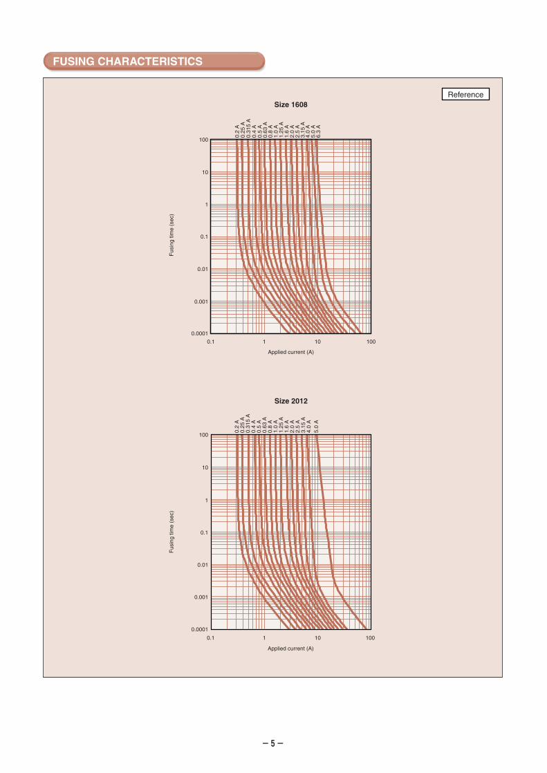
FUSING CHARACTERISTICS
0.0001
0.1 1 10 100
0.001
0.01
0.1
1
10
100
0.2
A0.
25 A
0.31
5 A
0.4
A0.
5 A
0.63
A0.
8 A
1.0
A1.
25 A
1.6
A2.
0 A
2.5
A3.
15 A
4.0
A5.
0 A
6.3
A
Applied current (A)
Size 1608Reference
Applied current (A)
0.2
A0.
25 A
0.31
5 A
0.4
A0.
5 A
0.63
A0.
8 A
1.0
A1.
25 A
1.6
A2.
0 A
2.5
A3.
15 A
4.0
A5.
0 A
0.1 1 10 100
Size 2012
Fus
ing
time
(sec
)F
usin
g tim
e (s
ec)
0.0001
0.001
0.01
0.1
1
10
100
-6-
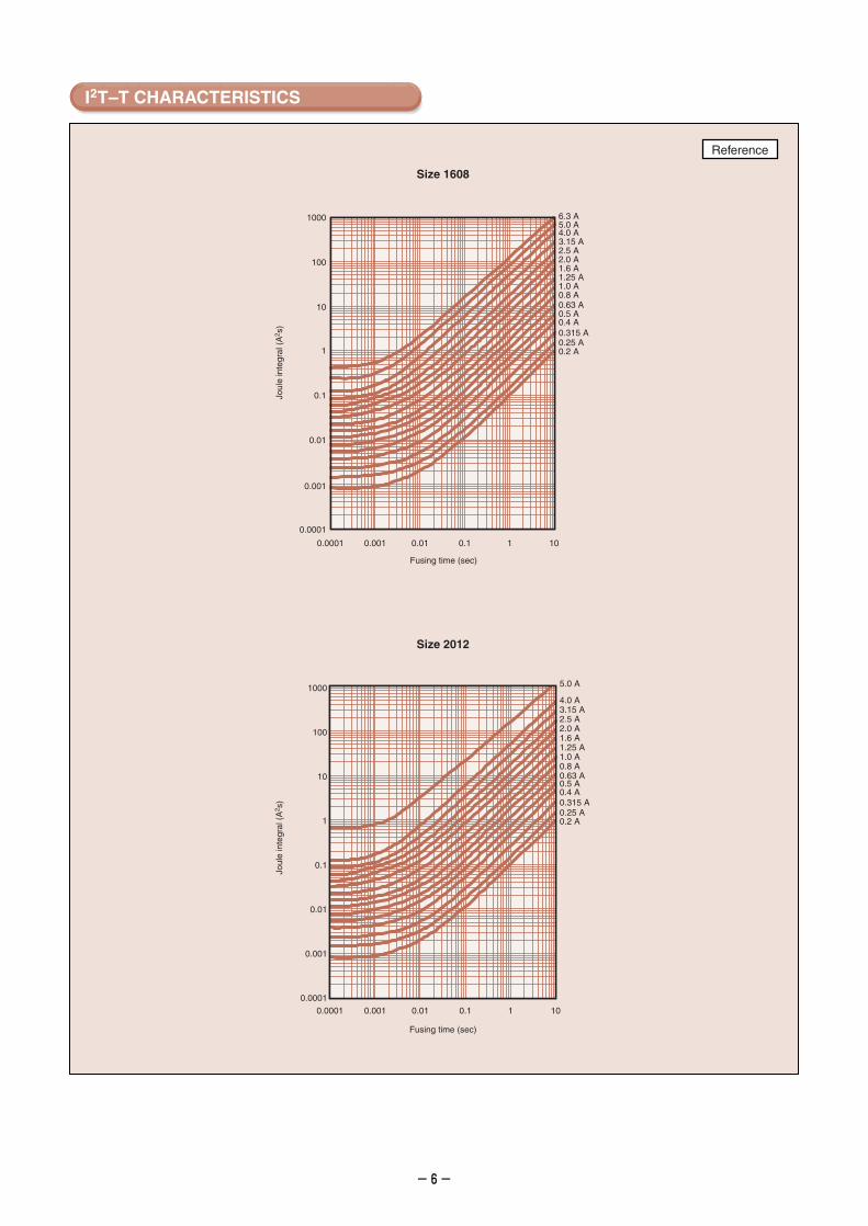
I2T–T CHARACTERISTICS
Fusing time (sec)
0.0001
0.001
0.01
0.1
1
10
100
1000
0.0001 0.001 0.01 0.1 1 10
6.3 A5.0 A4.0 A3.15 A2.5 A2.0 A1.6 A1.25 A1.0 A0.8 A0.63 A0.5 A0.4 A0.315 A0.25 A0.2 A
Size 1608
Fusing time (sec)
0.0001
0.001
0.01
0.1
1
10
100
1000 5.0 A
4.0 A3.15 A2.5 A2.0 A1.6 A1.25 A1.0 A0.8 A0.63 A0.5 A0.4 A0.315 A0.25 A0.2 A
0.0001 0.001 0.01 0.1 1 10
Size 2012
Joul
e in
tegr
al (
A2 s
)Jo
ule
inte
gral
(A
2 s)
Reference
-7-
100
10
1
0.1
0.01
0.001
0.00010.1 1 10 100
Applied current (A)
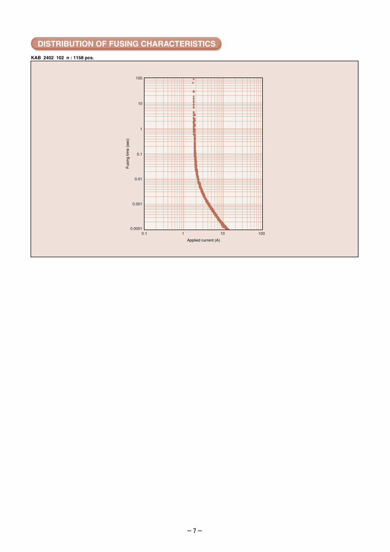
KAB 2402 102 n : 1158 pcs.
Fus
ing
time
(sec
)
DISTRIBUTION OF FUSING CHARACTERISTICS
-8-
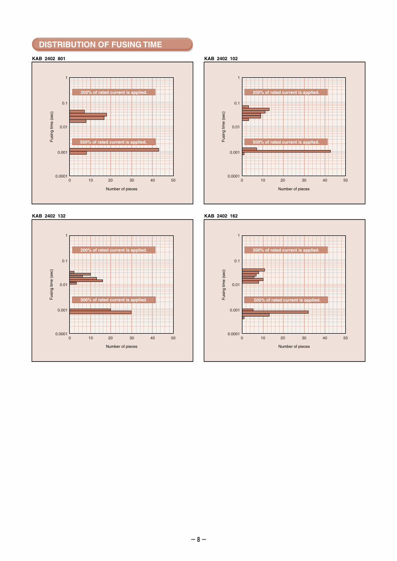
KAB 2402 801 KAB 2402 102
KAB 2402 132 KAB 2402 162
DISTRIBUTION OF FUSING TIME
200% of rated current is applied.
500% of rated current is applied.
1
0.1
0.01
0.001
0.00010 10 20 30 40 50
1
0.1
0.01
0.001
0.00010 10 20 30 40 50
200% of rated current is applied.
500% of rated current is applied.
200% of rated current is applied.
500% of rated current is applied.
200% of rated current is applied.
500% of rated current is applied.
Fus
ing
time
(sec
)
Fus
ing
time
(sec
)
Fus
ing
time
(sec
)
Fus
ing
time
(sec
)
Number of piecesNumber of pieces
Number of pieces Number of pieces
1
0.1
0.01
0.001
0.00010 10 20 30 40 50
1
0.1
0.01
0.001
0.00010 10 20 30 40 50
-9-
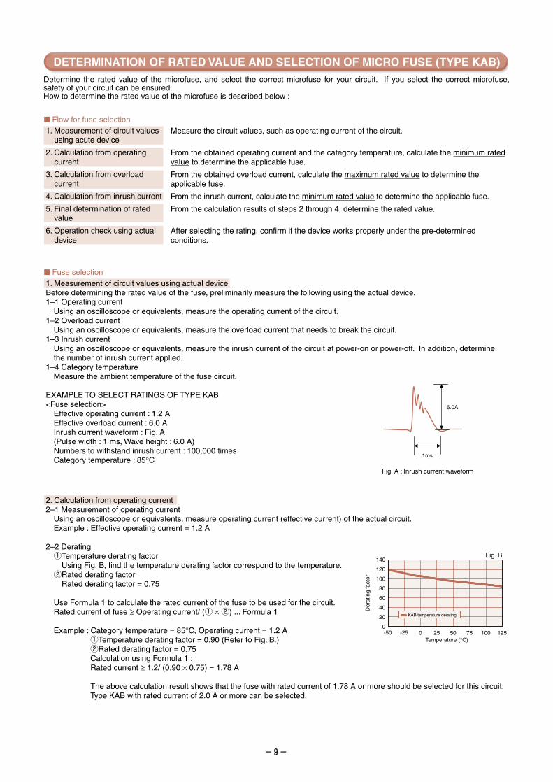
Flow for fuse selection1. Measurement of circuit values
using acute device
2. Calculation from operating current
3. Calculation from overload current
4. Calculation from inrush current
5. Final determination of rated value
6. Operation check using actual device
Measure the circuit values, such as operating current of the circuit.
From the obtained operating current and the category temperature, calculate the minimum rated value to determine the applicable fuse.
From the obtained overload current, calculate the maximum rated value to determine the applicable fuse.
From the inrush current, calculate the minimum rated value to determine the applicable fuse.
From the calculation results of steps 2 through 4, determine the rated value.
After selecting the rating, confirm if the device works properly under the pre-determined conditions.
Fuse selection1. Measurement of circuit values using actual deviceBefore determining the rated value of the fuse, preliminarily measure the following using the actual device.1–1 Operating current
Using an oscilloscope or equivalents, measure the operating current of the circuit.1–2 Overload current
Using an oscilloscope or equivalents, measure the overload current that needs to break the circuit.1–3 Inrush current
Using an oscilloscope or equivalents, measure the inrush current of the circuit at power-on or power-off. In addition, determine the number of inrush current applied.
1–4 Category temperatureMeasure the ambient temperature of the fuse circuit.
EXAMPLE TO SELECT RATINGS OF TYPE KAB<Fuse selection>
Effective operating current : 1.2 AEffective overload current : 6.0 AInrush current waveform : Fig. A(Pulse width : 1 ms, Wave height : 6.0 A)Numbers to withstand inrush current : 100,000 timesCategory temperature : 85°C
2. Calculation from operating current2–1 Measurement of operating current
Using an oscilloscope or equivalents, measure operating current (effective current) of the actual circuit.Example : Effective operating current = 1.2 A
2–2 DeratingqTemperature derating factor
Using Fig. B, find the temperature derating factor correspond to the temperature.wRated derating factor
Rated derating factor = 0.75
Use Formula 1 to calculate the rated current of the fuse to be used for the circuit.Rated current of fuse ≥ Operating current/ (q × w) ... Formula 1
Example : Category temperature = 85°C, Operating current = 1.2 AqTemperature derating factor = 0.90 (Refer to Fig. B.)wRated derating factor = 0.75Calculation using Formula 1 :Rated current ≥ 1.2/ (0.90 × 0.75) = 1.78 A
The above calculation result shows that the fuse with rated current of 1.78 A or more should be selected for this circuit.Type KAB with rated current of 2.0 A or more can be selected.
Determine the rated value of the microfuse, and select the correct microfuse for your circuit. If you select the correct microfuse, safety of your circuit can be ensured.How to determine the rated value of the microfuse is described below :
1ms
6.0A
Fig. A : Inrush current waveform
Fig. B
Der
atin
g fa
ctor
KAB temperature derating
Temperature (°C)-50 -25 0 25 50 75 100 125
0
20
40
60
80
100
120
140
DETERMINATION OF RATED VALUE AND SELECTION OF MICRO FUSE (TYPE KAB)
-10-
3. Calculation from overload current3–1 Measurement of overload current
Using an oscilloscope or equivalents, measure the overload current that needs to break the circuit.Example : Effective overload current = 6.0 A
3–2 Calculation from overload currentDetermine the rated current so that the overload current can be 2 times larger than the rated current.Use Formula 2 to calculate the rated current of the fuse.
Rated current of fuse ≤ Overload current/2.0 ... Formula 2
Example : Overload current = 6.0 A Use Formula 2 to calculate the rated current. Rated current ≤ 6.0/2.0 = 3.0 A
The above calculation result shows that the fuse with rated current of 3.0 A or less should be selected for this circuit.
Type KAB, with rated current of 2.5 A or less can be selected.
4. Calculation from inrush current4–1 Measurement of inrush current waveform
Using an oscilloscope or equivalent, measure the waveform of the inrush current of the actual circuit.
4–2 Creation of approximate waveformGenerally, the waveform of inrush current is complicated. For this reason, create the approximate waveform of inrush current as shown on Fig. C to simplify calculation.
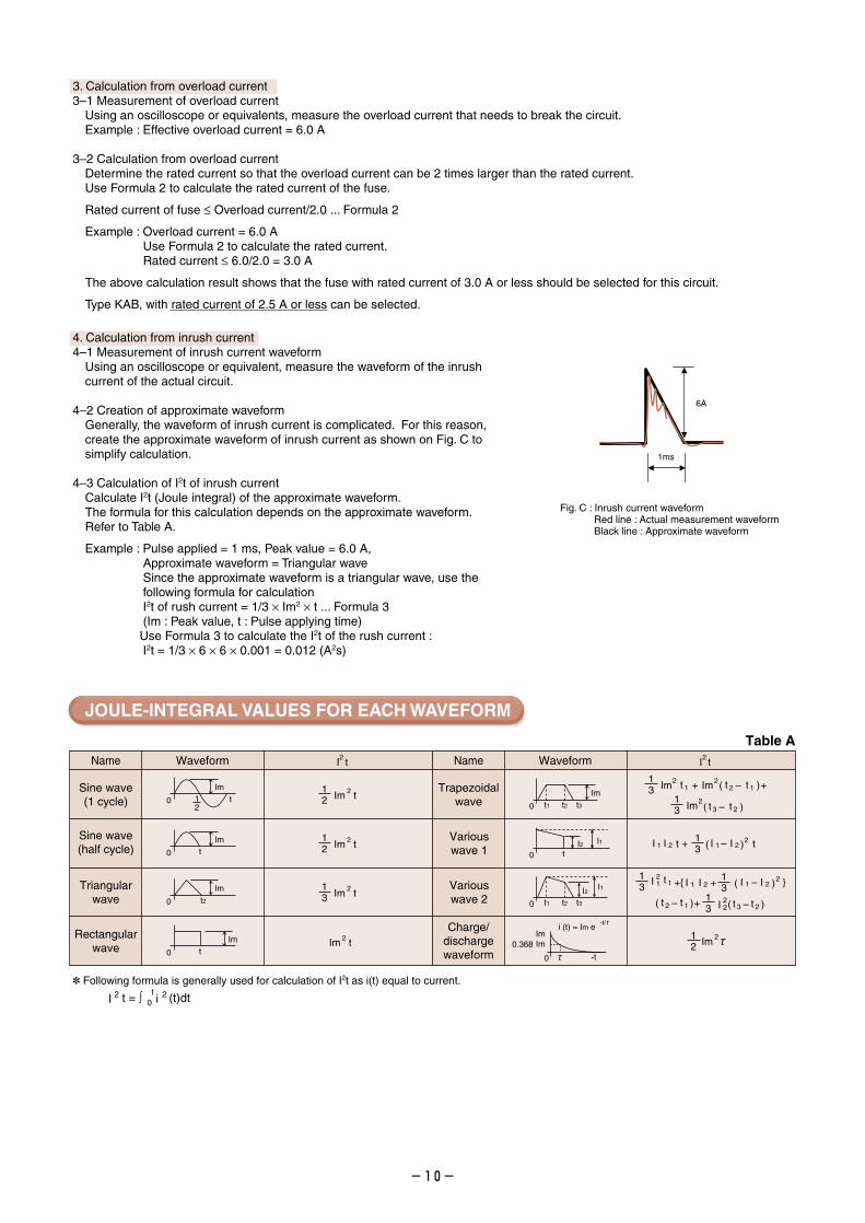
4–3 Calculation of I2t of inrush currentCalculate I2t (Joule integral) of the approximate waveform.The formula for this calculation depends on the approximate waveform.Refer to Table A.
Example : Pulse applied = 1 ms, Peak value = 6.0 A, Approximate waveform = Triangular wave Since the approximate waveform is a triangular wave, use the following formula for calculation I2t of rush current = 1/3 × Im2 × t ... Formula 3 (Im : Peak value, t : Pulse applying time)Use Formula 3 to calculate the I2t of the rush current : I2t = 1/3 × 6 × 6 × 0.001 = 0.012 (A2s)
JOULE-INTEGRAL VALUES FOR EACH WAVEFORM
1ms
6A
Name Waveform
Trapezoidalwave
Variouswave 1
Variouswave 2
Charge/dischargewaveform
I tName Waveform
Sine wave(1 cycle)
Triangularwave
Rectangularwave
I t
Sine wave(half cycle)
22
13I ( )+1 I 2 I –1 I 2
2 tt
13 tIm Im ( )+ +–2
13 Im2
21 t 2 t 1
( )–t 3 t 2
13
13
13+
+ I 12
I 22
( )I –1 I 22
( )–t 2 t 1
I +1 I 2
( )–t 3 t 2
t 1
0 t3t2t1Im
I2
0 t3t2t1
I1
I1I20 t
ImIm
0 -t
0.368
i (t) = Im e-t/
12 Im 2
0 12
tIm
0 tIm
12 tIm 2
12 tIm 2
13 tIm 2
tIm 2
0
Im
0 tIm
t2
Table A
I 2 20t
Following formula is generally used for calculation of I2t as i(t) equal to current.
t = ∫ (t)dti
Fig. C : Inrush current waveformRed line : Actual measurement waveformBlack line : Approximate waveform
-11-
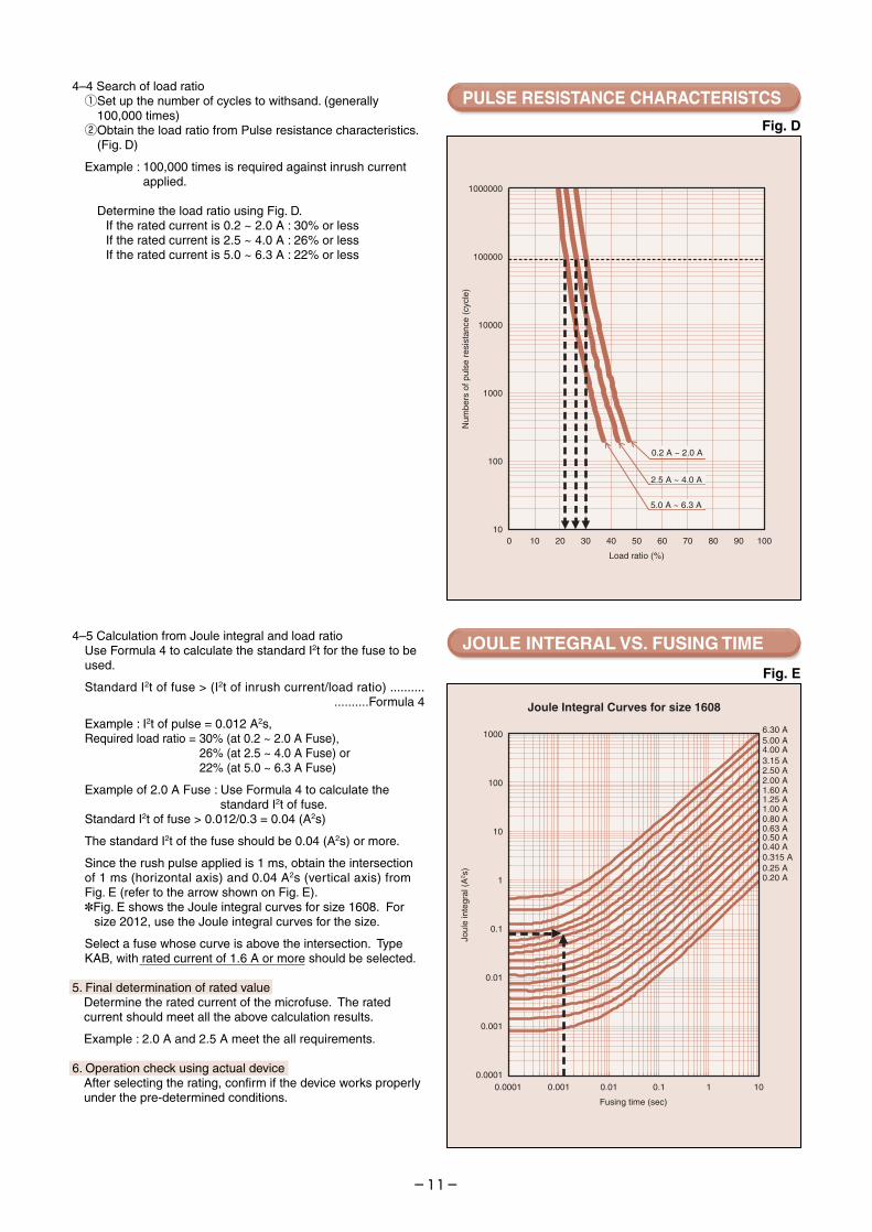
4–4 Search of load ratioqSet up the number of cycles to withsand. (generally
100,000 times)wObtain the load ratio from Pulse resistance characteristics.
(Fig. D)
Example : 100,000 times is required against inrush current applied.
Determine the load ratio using Fig. D.If the rated current is 0.2 ~ 2.0 A : 30% or lessIf the rated current is 2.5 ~ 4.0 A : 26% or lessIf the rated current is 5.0 ~ 6.3 A : 22% or less
4–5 Calculation from Joule integral and load ratioUse Formula 4 to calculate the standard I2t for the fuse to be used.
Standard I2t of fuse > (I2t of inrush current/load ratio) .......... ..........Formula 4
Example : I2t of pulse = 0.012 A2s,Required load ratio = 30% (at 0.2 ~ 2.0 A Fuse),
26% (at 2.5 ~ 4.0 A Fuse) or 22% (at 5.0 ~ 6.3 A Fuse)
Example of 2.0 A Fuse : Use Formula 4 to calculate the standard I2t of fuse.Standard I2t of fuse > 0.012/0.3 = 0.04 (A2s)
The standard I2t of the fuse should be 0.04 (A2s) or more.
Since the rush pulse applied is 1 ms, obtain the intersection of 1 ms (horizontal axis) and 0.04 A2s (vertical axis) from Fig. E (refer to the arrow shown on Fig. E). Fig. E shows the Joule integral curves for size 1608. For
size 2012, use the Joule integral curves for the size.
Select a fuse whose curve is above the intersection. Type KAB, with rated current of 1.6 A or more should be selected.
5. Final determination of rated valueDetermine the rated current of the microfuse. The rated current should meet all the above calculation results.
Example : 2.0 A and 2.5 A meet the all requirements.
6. Operation check using actual deviceAfter selecting the rating, confirm if the device works properly under the pre-determined conditions.
Fig. D
Fig. E
PULSE RESISTANCE CHARACTERISTCS
JOULE INTEGRAL VS. FUSING TIME
Fusing time (sec)
Joul
e in
tegr
al (
A2 s
)
6.30 A
Joule Integral Curves for size 1608
5.00 A4.00 A3.15 A2.50 A2.00 A1.60 A1.25 A1.00 A0.80 A0.63 A
0.40 A0.315 A0.25 A0.20 A
0.50 A
0.001 0.01 0.1 10.0001 10
0.001
0.01
0.1
1
10
100
1000
0.0001
Load ratio (%)
0.2 A ~ 2.0 A
2.5 A ~ 4.0 A
5.0 A ~ 6.3 A
100
1000
10000
100000
10
1000000
Num
bers
of p
ulse
res
ista
nce
(cyc
le)
10 20 30 40 50 60 70 80 900 100
The specifications on this catalog are subject to change without prior notice. Please inquire of our Sales Department to confirm the specifications prior to use.
-12-
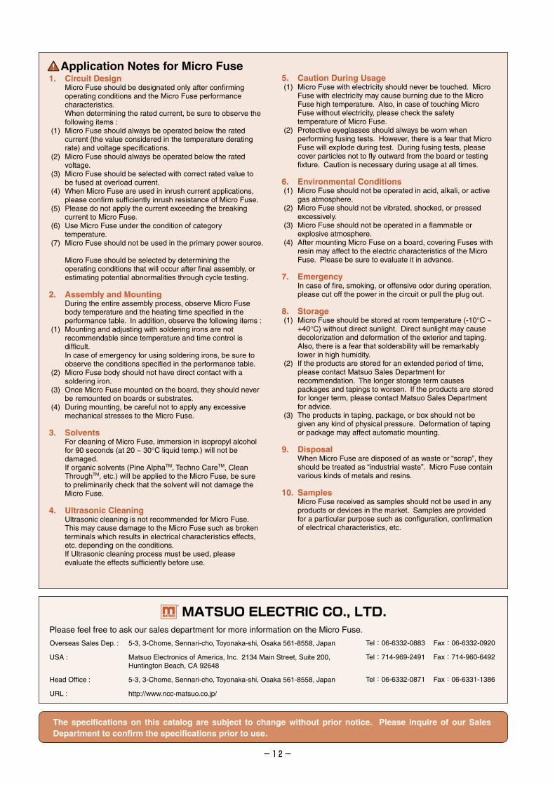
1. Circuit DesignMicro Fuse should be designated only after confirming operating conditions and the Micro Fuse performance characteristics.When determining the rated current, be sure to observe the following items :
(1) Micro Fuse should always be operated below the rated current (the value considered in the temperature derating rate) and voltage specifications.
(2) Micro Fuse should always be operated below the rated voltage.
(3) Micro Fuse should be selected with correct rated value to be fused at overload current.
(4) When Micro Fuse are used in inrush current applications, please confirm sufficiently inrush resistance of Micro Fuse.
(5) Please do not apply the current exceeding the breaking current to Micro Fuse.
(6) Use Micro Fuse under the condition of category temperature.
(7) Micro Fuse should not be used in the primary power source.
Micro Fuse should be selected by determining the operating conditions that will occur after final assembly, or estimating potential abnormalities through cycle testing.
2. Assembly and MountingDuring the entire assembly process, observe Micro Fuse body temperature and the heating time specified in the performance table. In addition, observe the following items :
(1) Mounting and adjusting with soldering irons are not recommendable since temperature and time control is difficult.In case of emergency for using soldering irons, be sure to observe the conditions specified in the performance table.
(2) Micro Fuse body should not have direct contact with a soldering iron.
(3) Once Micro Fuse mounted on the board, they should never be remounted on boards or substrates.
(4) During mounting, be careful not to apply any excessive mechanical stresses to the Micro Fuse.
3. SolventsFor cleaning of Micro Fuse, immersion in isopropyl alcohol for 90 seconds (at 20 ~ 30°C liquid temp.) will not be damaged.If organic solvents (Pine AlphaTM, Techno CareTM, Clean ThroughTM, etc.) will be applied to the Micro Fuse, be sure to preliminarily check that the solvent will not damage the Micro Fuse.
4. Ultrasonic CleaningUltrasonic cleaning is not recommended for Micro Fuse. This may cause damage to the Micro Fuse such as broken terminals which results in electrical characteristics effects, etc. depending on the conditions.If Ultrasonic cleaning process must be used, please evaluate the effects sufficiently before use.
5. Caution During Usage (1) Micro Fuse with electricity should never be touched. Micro
Fuse with electricity may cause burning due to the Micro Fuse high temperature. Also, in case of touching Micro Fuse without electricity, please check the safety temperature of Micro Fuse.
(2) Protective eyeglasses should always be worn when performing fusing tests. However, there is a fear that Micro Fuse will explode during test. During fusing tests, please cover particles not to fly outward from the board or testing fixture. Caution is necessary during usage at all times.
6. Environmental Conditions (1) Micro Fuse should not be operated in acid, alkali, or active
gas atmosphere. (2) Micro Fuse should not be vibrated, shocked, or pressed
excessively. (3) Micro Fuse should not be operated in a flammable or
explosive atmosphere. (4) After mounting Micro Fuse on a board, covering Fuses with
resin may affect to the electric characteristics of the Micro Fuse. Please be sure to evaluate it in advance.
7. EmergencyIn case of fire, smoking, or offensive odor during operation, please cut off the power in the circuit or pull the plug out.
8. Storage (1) Micro Fuse should be stored at room temperature (-10°C ~
+40°C) without direct sunlight. Direct sunlight may cause decolorization and deformation of the exterior and taping. Also, there is a fear that solderability will be remarkably lower in high humidity.
(2) If the products are stored for an extended period of time, please contact Matsuo Sales Department for recommendation. The longer storage term causes packages and tapings to worsen. If the products are stored for longer term, please contact Matsuo Sales Department for advice.
(3) The products in taping, package, or box should not be given any kind of physical pressure. Deformation of taping or package may affect automatic mounting.
9. DisposalWhen Micro Fuse are disposed of as waste or “scrap”, they should be treated as “industrial waste”. Micro Fuse contain various kinds of metals and resins.
10. SamplesMicro Fuse received as samples should not be used in any products or devices in the market. Samples are provided for a particular purpose such as configuration, confirmation of electrical characteristics, etc.
Application Notes for Micro Fuse
Overseas Sales Dep. :
USA :
Head Office :
URL :
5-3, 3-Chome, Sennari-cho, Toyonaka-shi, Osaka 561-8558, Japan
Matsuo Electronics of America, Inc. 2134 Main Street, Suite 200, Huntington Beach, CA 92648
5-3, 3-Chome, Sennari-cho, Toyonaka-shi, Osaka 561-8558, Japan
http://www.ncc-matsuo.co.jp/
Please feel free to ask our sales department for more information on the Micro Fuse.
Tel : 06-6332-0883
Tel : 714-969-2491
Tel : 06-6332-0871
Fax : 06-6332-0920
Fax : 714-960-6492
Fax : 06-6331-1386