Embed Size (px)
Citation preview
Plastic Film Capacitor
Products CatalogProducts Catalog
2018.2 http://industrial.panasonic.com/ww/products/capacitors/film-capacitors
2018
Electronic Equipment UseAC Motor Use
Automotive, Industrial and Infrastructure Use

INDEX
・ Electronic Equipment Use
Stacked Metallized PPS Film Chip CapacitorECHU (X)ECHU (C)ECWU (X)ECWU (C)ECWU (V16)ECPU (A)ECQE (F)ECQE (B)ECQE (T)ECWF (L)ECWF (A)ECWFDECWFEECWH (V)ECWH (A)ECWH (C)TMFECQUAECQULECQUG
AMFDMFPMF/SMF
Type1EZPEEZPE (Low profile type)EZPQ
・ Automotive, Industrial and Infrastructure Use
Metallized Polyester Film Capacitor for Noise Suppression of Automobile DC-Link Film Capacitor
Film Capacitor for AC Motor
・ AC Motor Use
Dielectric Series
Dielectric Series
Dielectric Series
NEW
Metallized Polypropylene Film Capacitor
ECQE
Stacked Metallized PEN Film Chip Capacitor
Stacked Metallized Plastic Film Chip Capacitor
Metallized Polyester Film Capacitor
Metallized Polypropylene Film Capacitor
Metallized Polypropylene Film CapacitorMetallized Polyester Film Capacitor
Design and specifications are each subject to change without notice. Ask factory for the current technical specifications before purchase and/or use.
Should a safety concern arise regarding this product, please be sure to contact us immediately.
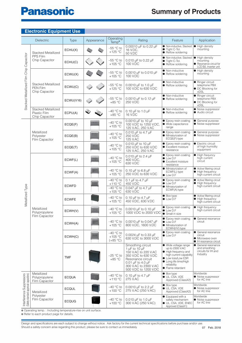
Summary of Products
Dielectric Type AppearanceOperating
Temp✽ Rating Feature Application
Sta
cked
Meta
llized
Film
Chip
Cap
acitor Stacked Metallized
PPS Film Chip Capacitor
ECHU(X) –55 °C to+125 °C
0.00010 μF to 0.22 μF16 V.DC, 50 V.DC
● Non-inductive, Stacked● Tight C-Tol.● Refl ow soldering
● High density mounting
ECHU(C) –55 °C to+105 °C
0.010 μF to 0.22 μF100 V.DC
● Non-inductive, Stacked● Tight C-Tol.● Refl ow soldering
● High density mounting
● Resonance circuit for LCD B/L inverter unit
Stacked MetallizedPEN Film Chip Capacitor
ECWU(X) –55 °C to+105 °C
0.0010 μF to 0.010 μF100 V.DC
● Non-inductive● Refl ow soldering
● High density mounting
ECWU(C) –55 °C to+125 °C
0.0010 μF to 1.0 μF100 V.DC to 630 V.DC
● Non-inductive● Refl ow soldering
● Ringer circuit telephone PBX
● DC Blocking for xDSL
ECWU(V16) –55 °C to+85 °C
0.0010 μF to 0.12 μF250 V.DC
● Non-inductive● Refl ow soldering
● Ringer circuit telephone PBX
● DC Blocking for xDSL
Stacked MetallizedPlastic FilmChip Capacitor
ECPU(A) –40 °C to+85 °C
0.10 μF to 1.0 μF16 V.DC
● Non-inductive● Refl ow soldering
● Noise suppressor● Audio circuit
Meta
llized
Typ
e
MetallizedPolyesterFilm Capacitor
ECQE(F) –40 °C to+105 °C
0.0010 μF to 10 μF100 V.DC to 1250 V.DC,125 V.AC, 250 V.AC
● Epoxy resin coating● Wide capacitance
range
● General purpose● Noise suppressor
ECQE(B) –40 °C to+105 °C
0.010 μF to 4.7 μF250 V.DC125 V.AC
● Epoxy resin coating● Miniaturization of
ECQE(F) type
● General purpose● Noise suppressor
ECQE(T) –40 °C to+105 °C
0.010 μF to 10 μF250 V.DC to 630 V.DC125 V.AC, 250 V.AC
● Epoxy resin coating● Excellent moisture
resistance
● Electric circuit of high humidity equipment
MetallizedPolypropylene Film Capacitor
ECWF(L) –40 °C to+105 °C
0.010 μF to 2.4 μF400 V.DC, 630 V.DC
● Epoxy resin coating● Low D.F● Excellent moisture
resistance
● High frequncy high current circuit
ECWF(A) –40 °C to+105 °C
0.10 μF to 6.8 μF250 V.DC to 630 V.DC
● Miniaturization of ECWF(L) type
● Low D.F
● Active fi ltering circuit● High frequency
high current circuit
ECWFD
–40 °C to+110 °C
0.1 μF to 4.7 μF450 V.DC
● Epoxy resin coating● Low D.F● Miniaturization of
ECWF(A) type
● Active fi ltering circuit● High frequency
high current circuit–40 °C to+105 °C
0.047 μF to 4.7 μF630 V.DC
ECWFE –40 °C to+105 °C
0.10 μF to 4.7 μF450 V.DC, 630 V.DC
● Box type● Low D.F
● Active fi ltering circuit● High frequency
high current circuit
ECWH(V) –40 °C to+105 °C
0.0010 μF to 0.10 μF1000 V.DC to 2000 V.DC
● Epoxy resin coating● Low D.F● Small in size
● High frequency high current circuit
ECWH(A) –40 °C to+105 °C
0.0010 μF to 0.047 μF800 V.DC, 1600 V.DC
● Epoxy resin coating● Low D.F● Miniaturization of
ECWH(VV) type
● General resonance circuit
ECWH(C)–40 °C to+105 °C(+85 °C)
0.0024 μF to 0.33 μF630 V.DC to 3000 V.DC
● Epoxy resin coating● Low D.F
● General resonance circuit
● Microwave oven● IH resonance circuit
TMF –25 °C to+85 °C
Smoothing circuit1 μF to 10 μF150 V.AC to 220 V.AC350 V.DC to 630 V.DCResonance circuit0.01 μF to 4.0 μF300 V.AC to 2300 V.AC500 V.DC to 1200 V.DC
● Wide voltage range up to 2300 V.AC
● High frequency and high current capability
● Low loss/Low ESR● Long life time/High
reliability● Flame retardant
● General resonance and smoothing circuits for IH and Industry
Inte
rfere
nce S
up
pre
ssors
(Saf
ety s
tand
ard
appr
oval
capa
citor
s) MetallizedPolypropylene Film Capacitor
ECQUA –40 °C to+110 °C
0.10 μF to 4.7 μF275 V.AC
● Box type● UL, CSA, VDE Approved (ClassX2)
Worldwide● Noise suppressor
for AC line
MetallizedPolyester Film Capacitor
ECQUL –40 °C to+100 °C
0.0010 μF to 2.2 μF275 V.AC (250 V.AC)
● Box type● UL, CSA, VDE Approved (ClassX2)
Worldwide● Noise suppressor
for AC line
ECQUG –40 °C to+100 °C
0.010 μF to 1.0 μF300 V.AC (250 V.AC)
● Equipped with a safety mechanism
● UL, CSA, VDE, ENEC Approved (ClassX1)
Worldwide● Noise suppressor
for AC line
✽ Operating temp. : Including temperature-rise on unit surface.
✽ Refer to each product page for details.
Electronic Equipment Use
Feb. 201807

Design and specifications are each subject to change without notice. Ask factory for the current technical specifications before purchase and/or use.
Should a safety concern arise regarding this product, please be sure to contact us immediately.
Summary of Products
Dielectric Type AppearanceOperating
Temp✽ Rating Feature Application
Film Capacitor for AC Motor
AMF –25 °C to+70 °C
10 μF to 40 μF180 V.AC to 440 V.AC
● High safety (safety function installed)
● High reliability● Small size, lightness,
and low loss
● Motor and compressor
(for running)
DMF –25 °C to+70 °C
10 μF to 60 μF180 V.AC to 450 V.AC
● High safety (with built-in safety device)
● High reliability, safety standard approval
● Small size, lightness, and low loss
● Motor and compressor
(for running)
PMF/SMF –25 °C to+70 °C
0.5 μF to 65 μF150 V.AC to 500 V.AC
● High safety (safety function installed)
● High reliability, safety standard approval
● Small size, lightness, and low loss
● Motor and small compressor
(for running)
Dielectric Type AppearanceOperating
Temp✽ Rating Feature Application
Metallized PolyesterFilm Capacitor for NoiseSuppression of Automobile
ECQE –40 °C to+130 °C
0.47 μF, 2.2 μF, 4.7 μF
250 V.DC
● Box type ● Noise suppressor for automobile
DC-Link Film Capacitor
Type1 –40 °C to+105 °C
581 μF
450 V.DC
● High safety, Self-healing and Self-protecting function built in.
● No catastrophic failure upon natural end of life due to inbuilt fuse function
● Any automotive and/or other application requiring DC Linkage
Metallized Polypropylene Film Capacitors
EZPE –40 °C to+85 °C
10 μF to 110 μF
500 V.DC to 1300 V.DC
● High safety, Self-healing and Self-protecting function built-in
● Long product life, High reliability● Low loss, Low ESR● Flame retardant
● DC fi ltening● DC link circuit
EZPE(Low profile type)
–40 °C to+85 °C
29 μF : 450 V.DC
66 μF : 525 V.DC
12 μF : 575 V.DC
10 μF : 630 V.DC
● High safety, Self-healing and Self-protecting function built-in
● Long product life, High reliability, High moisture resistance● Low loss, Low ESR● Flame retardant
● Solar inverters, Micro inverters
● Wind power generation
● Industrial power supplies
● Inverter circuit in appliances (Air Conditioners etc.)
EZPQ –40 °C to+85 °C
12 μF to 36 μF
250 V.AC
● High safety, Self-healing and Self-protecting function built-in
● Long product life, High reliability, ● Low loss, Low ESR● Flame retardant● Super high moisture
resistance (85 °C, 85 %RH)
● AC Filter
✽ Operating temp. : Including temperature-rise on unit surface.
✽ Refer to each product page for details.
✽ The range of IEC approval is different depending on each approval.
AC Motor Use
Automotive, Industrial and Infrastructure Use
NEW
Feb. 201807

Design and specifications are each subject to change without notice. Ask factory for the current technical specifications before purchase and/or use.
Should a safety concern arise regarding this product, please be sure to contact us immediately.
Series system diagram
Hight voltage andHigh current
Middle voltage andHigh current
Case of ECWFD type
Series system diagram
Stacked Metallized PPS FilmChip Capacitor
Stacked Metallized PEN FilmChip Capacitor
Surface mounting type
Stacked Metallized Plastic FilmChip Capacitor
ECPU(A)
Volt. : 16 V.DCTemp. : −40 ˚C to +85 ˚CCap. : 0.10 μF to 1.0 μF
Small in size and largecapacitance
Audio circuit etc.ECWU(X)
Volt. : 100 V.DCTemp. : −55 ˚C to +105 ˚CCap. : 0.0010 μF to 0.010 μF
General- purpose
High density surfacemounting
ECWU(V16)
Special application
DC Blocking for xDSL
Volt. : 250 V.DCTemp. : −55 ˚C to +85 ˚CCap. : 0.0010 μF to 0.12 μF
ECWU(C)
Volt. : 100 V.DC to 630 V.DCTemp. : −55 ˚C to +125 ˚CCap. : 0.0010 μF to 1.0 μF
General- purpose
Ringer circuit for telephone, PBX etc.
High performance
High density surfacemounting
ECHU(X)
Volt. : 16 V.DC to 50 V.DCTemp. : −55 ˚C to +125 ˚CCap. : 0.00010 μF to 0.22 μF
ECHU(C)
High performance
High density surfacemounting
Volt. : 100 V.DCTemp. : −55 ˚C to +105 ˚CCap. : 0.010 μF to 0.22 μF
ECQE(B)
Volt. : 250 V.DC 125 V.AC
Temp. : −40 ˚C to +105 ˚C Cap. : 0.010 μF to 4.7 μF
Miniaturization of ECQE(F)
General-purpose
ECQE(F)
Volt. : 100 V.DC to 1250 V.DC 125 V.AC to 250 V.ACTemp. : −40 ˚C to +105 ˚C
Cap. : 0.0010 μF to 10.0 μF
Standard
General-purpose
ECQE
Special applicationCase type
Noise suppressorfor automobile
Volt. : 250 V.DCTemp. : −40 ˚C to +130 ˚C
Cap. : 0.47, 2.2, 4.7 μF
ECQE(T)
Volt. : 250 V.DC to 630 V.DC 125 V.AC, 250 V.AC
Temp. : −40 ˚C to +105 ˚CCap. : 0.010 μF to 10.0 μF
High humidity type
Lighting, Automotive etc.(85 °C, 85 % guarantee)
Product for Class X2Case type
Across-The- Line capacitors forpower supply
Equipped with a safety mechanism
ECQUA
Volt. : 275 V.AC
Temp. : −40 ˚C to +110 ˚C
Cap. : 0.10 μF to 4.7 μF
Product for Class X2Case type
Across-The- Line capacitors forpower supply
Equipped with a safety mechanism
ECQULVolt. : 275 V.AC (IEC60384−14)
250 V.AC (UL/CSA)Temp. : −40 ˚C to +100 ˚C
(UL/CSA : 85 ˚C max)Cap. : 0.0010 μF to 2.2 μF
Product for Class X1Case type
Across-The- Line capacitors forpower supply
Equipped with a safety mechanism ECQUG
Volt. : 300 V.AC (IEC60384−14) 250 V.AC (UL/CSA)
Temp. : −40 ˚C to +100 ˚C(UL/CSA : 85 ˚C max)
Cap. : 0.010 μF to 1.0 μF
ECWF(L)
High frequency andHigh current circuit
Volt. : 400 V.DC to 630 V.DCTemp. : −40 ˚C to +105 ˚CCap. : 0.010 μF to 2.4 μF
ECWF(A)
Miniaturization of ECWF(L) type
Active filtering circuitHigh frequency andHigh current circuit
Equipped with a safety mechanism
Volt. : 250 V.DC to 630 V.DCTemp. : −40 ˚C to +105 ˚CCap. : 0.10 μF to 6.8 μF
ECWH(V)
High frequency andHigh current circuit
Volt. : 1000 V.DC to 2000 V.DCTemp. : −40˚C to +105 ˚CCap. : 0.0010 μF to 0.1 μF
ECWFD
Miniaturization of ECWF(A) type
Active filtering circuitHigh frequency
Equipped with a safety mechanism
Volt. : 450V.DC, 630V.DCTemp. : −40 ˚C to +110 ˚C (450 V.DC) −40 ˚C to +105 ˚C (630 V.DC)
Cap. : 0.047 μF to 4.7 μF
ECWFE
Active filtering circuitHigh frequency
Equipped with a safety mechanism
Volt. : 450V.DC, 630V.DCTemp. : −40 ˚C to +105 ˚C
Cap. : 0.1 μF to 4.7 μF
ECWH(A)
High frequency andHigh current circuit
Volt. : 800 V.DC to 1600 V.DCTemp. : −40 ˚C to +105 ˚CCap. : 0.0010 μF to 0.047 μF
ECWH(C)
Resonace circuit
Microwave ovenIH resonance circuit
Volt. : 630 V.DC to 3000 V.DCTemp. : −40 ˚C to +105 ˚CCap. : 0.0024 μF to 0.33 μF
Safety Standard Approval Metallized Film Capacitor
Metallized PolyesterFilm Capacitor
Metallized PolypropyleneFilm Capacitor
Radial lead type
UL, CSA, VDE approved0.001 μF to 0.0068 μF : (ClassY2/X2)
UL, CSA, VDE approved UL, CSA, ENEC approved
Miniaturization of ECWH(V) type
PP PET PET
NEW
Feb. 201803

Design and specifications are each subject to change without notice. Ask factory for the current technical specifications before purchase and/or use.
Should a safety concern arise regarding this product, please be sure to contact us immediately.
Main Applications & Main Products
+−
+
−ECPUPWM
ECPU
ECHUECWU
ECHUECWUWave generator
EC
HU
EC
HU
EC
QE
· E
CW
F
EC
QE
· E
CW
F
EC
QE
EC
WF
EC
QE
EC
WF
EC
QE
EC
WF
EC
QU
A ·
EC
QE
(AC
)E
CQ
UG
· E
CQ
UL
EC
QU
A ·
EC
QE
(AC
)E
CQ
UG
· E
CQ
UL
EC
QU
LE
CQ
UL
EC
QE
· E
CW
F
EC
QE
EC
WF
EC
QU
A ·
EC
QE
(AC
)
EC
QU
A ·
EC
QE
(AC
)
ECQE · ECWF
EC
WH
Lighting
Switching Power Supply
Audio Non-contact charger
Cha
rge
cont
rol
circ
uit
EC
HU
EC
WH
EC
WF
EC
HU
EC
WH
EC
WF
Sep. 201702

Design and specifications are each subject to change without notice. Ask factory for the current technical specifications before purchase and/or use.
Should a safety concern arise regarding this product, please be sure to contact us immediately.
Main Applications & Main Products
144 V to
Microwave oven(IH)
Automobile
xDSL
PhoneLine
ECWUECQE
TX
RX
ECHU
ECHU
EC
HU
EC
HUECHU
ECWUECQE
ECHU
Hybrid car
Smart Keyless Ignition
DC/DC Converters
EC
WF
ECWF12 V
ECHUWireless
Igniter
Noise Suppressionof AutomobileE
CQ
E
EC
QU
A E
CQ
UG
EC
QU
A E
CQ
UG
EC
WF
EC
QE
· E
CQ
UL
(AC
)
EC
QE
· E
CQ
UL
(AC
)
EC
WH
Sep. 201702

Design and specifications are each subject to change without notice. Ask factory for the current technical specifications before purchase and/or use.
Should a safety concern arise regarding this product, please be sure to contact us immediately.
Permissible AC voltage corresponding to DC rated voltage
1. In case of applying voltage in alternating current (50 Hz or 60 Hz sine wave) to a capacitor, permissible
voltage (R.M.S) in alternating current is shown in the following table.
2. Permissible voltage (R.M.S) in alternating current is not an AC rated voltage.
3. The capacitor of DC rating should not be used at the primary side of power supplies.
4. The peak value (zero-to-peak) including pulse of voltage applied capacitor of DC rating should be less than
DC rated voltage.
The permissible pulse current is different in each type of the capacitor, please request the product
specifi cations.
5. Please request the product specifi cations or consult us about details of permissible voltage (R.M.S) in
alternating current.
Permissible voltage (R.M.S) in alternating current corresponding to DC Rated voltage
Type & SeriesRated voltage
(V.DC)
Permissible voltage
(R.M.S) in
alternating current
(V.AC)
ECHU(X)ECHU1C(X) 16 11
ECHU1H(X) 50 30
ECHU(C) ECHU1(C) 100 40
ECWU(X) ECWU1(X) 100 40
ECWU(C)ECWU1(C) 100 40
ECWU2(C) 250 125
ECWUC2J 630 250
ECPU(A) ECPU1C(A) 16 12
ECQE(F)
ECQE1(F) 100 63
ECQE2(F) 250 150
ECQE4(F) 400 200
ECQE6(F) 630 250
ECQE10(F) 1000 400
ECQE12(F) 1250 500
ECQE(B) ECQE2(B) 250 125
ECQE(T)ECQE2(T) 250 150
ECQE4(T) 400 200
ECQE6(T) 630 250
ECWF(A)ECWF2(A) 250 125
ECWF2W(A) 450 84
ECWFA2J 630 141
ECWFDECWFD2W 450 84
ECWFD2J 630 141
ECWFEECWFE2W 450 84
ECWFE2J 630 141
ECWF(L)ECWF4(L) 400 141
ECWF6(L) 630 223
ECWH(A)ECWH8(A) 800 283
ECWHA3C 1600 700
ECWH(C)ECWH6(C) 630 223
ECWHC3B 1250 450
ECWHC3F 3000 1060
ECWH(V)
ECWH10(V) 1000 283
ECWH12(V) 1250 354
ECWH16(V) 1600 424
ECWH20(V) 2000 531
Sep. 201704

Design and specifications are each subject to change without notice. Ask factory for the current technical specifications before purchase and/or use.
Should a safety concern arise regarding this product, please be sure to contact us immediately.
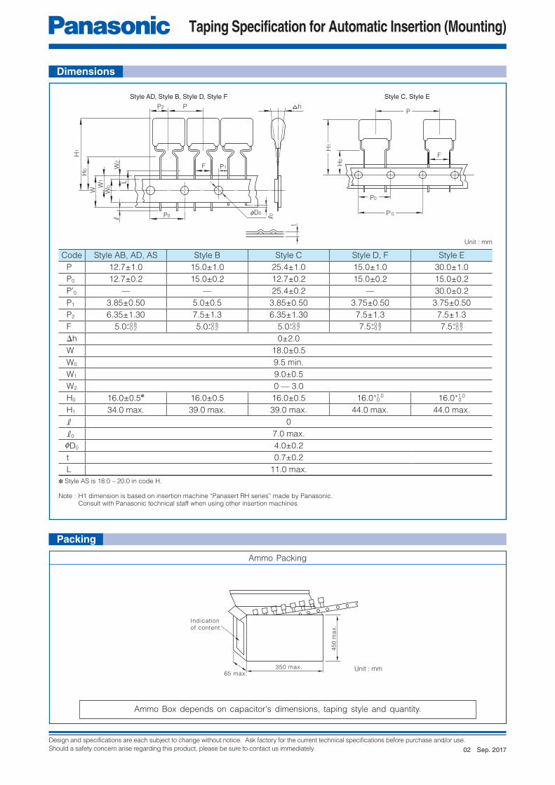
Taping Specification for Automatic Insertion (Mounting)
Style ADP
F
H1
H0
P0 P0
Style AS
P
FH1
1M
AX
H
Style ABP
F
H1
H0
P0
FH1
H0
P0
P
F
Style CStyle B
P
P0
H1
H0
Style D
F
P
P0
H0
H1
F
Style E Style F
PP
P0 P0
H1
H0 FH
1
H0
Taping type
Shape Name Specifi cation Taping style
Radial type
Standard taping 5 mm lead spacing with 12.7 mm body width AD, AS, AB
Odd size taping (I) 5 mm, 7.5 mm lead spacing with 15 mm & up
body widthB, C, D, E, F
Odd size taping (II) Other than above Please consult
Chip type Embossed taping Apply for chip type8 mm, 12 mm, 16 mm, 24 mm
carrier tape
P 12.7 12.7 12.7
P0 12.7 12.7 12.7
F 5.0 5.0 5.0
H0 16.0 (H)18.0 — 20.0 16.0
H1 34.0 max. 34.0 max. 34.0 max.
P 15.0 25.4 15.0 30.0 15.0
P0 15.0 12.7 15.0 15.0 15.0
F 5.0 5.0 7.5 7.5 7.5
H0 16.0 16.0 16.0 16.0 16.0
H1 39.0 max 39.0 max. 44.0 max. 44.0 max. 44.0 max.
● Standard taping
● Odd size taping (I)
● Odd size taping (II) If the specifi cation of taping is changed by various conditions, including, dimensions, lead spacing and
insertion machine, please contact the nearest sales offi ce for further information.
Note : H1 dimension is based on insertion machine “Panasert RH series” made by Panasonic.
Consult with Panasonic technical staff when using other insertion machines.
Note : H1 dimension is based on insertion machine “Panasert RH series” made by Panasonic.
Consult with Panasonic technical staff when using other insertion machines.
Unit : mm Unit : mm Unit : mm
Unit : mm Unit : mm Unit : mmUnit : mm Unit : mm
Radial type taping
Sep. 201702
Design and specifications are each subject to change without notice. Ask factory for the current technical specifications before purchase and/or use.
Should a safety concern arise regarding this product, please be sure to contact us immediately.
Taping Specification for Automatic Insertion (Mounting)
450 m
ax
.
350 max.65 max.
Indication
of content
Style AD, Style B, Style D, Style F
P hP2
F P1
H1
W
W1
H0
P0
W2
L
fD0
k0
t
F
Style C, Style E
P
P0
P'0
H1
H0
W0
k
Dimensions
Packing
✽ Style AS is 18.0 – 20.0 in code H.
Note : H1 dimension is based on insertion machine “Panasert RH series” made by Panasonic. Consult with Panasonic technical staff when using other insertion machines.
Ammo Packing
Ammo Box depends on capacitor's dimensions, taping style and quantity.
Code Style AB, AD, AS Style B Style C Style D, F Style E
P 12.7±1.0 15.0±1.0 25.4±1.0 15.0±1.0 30.0±1.0
P0 12.7±0.2 15.0±0.2 12.7±0.2 15.0±0.2 15.0±0.2
P’0 — — 25.4±0.2 — 30.0±0.2
P1 3.85±0.50 5.0±0.5 3.85±0.50 3.75±0.50 3.75±0.50
P2 6.35±1.30 7.5±1.3 6.35±1.30 7.5±1.3 7.5±1.3
F 5.0+0.8 5.0+0.8 5.0+0.8 7.5+0.8 7.5+0.8
Δh 0±2.0
W 18.0±0.5
W0 9.5 min.
W1 9.0±0.5
W2 0 — 3.0
H0 16.0±0.5✽ 16.0±0.5 16.0±0.5 16.0+1.0 16.0+1.0
H1 34.0 max. 39.0 max. 39.0 max. 44.0 max. 44.0 max.
k 0
k0 7.0 max.
0D0 4.0±0.2
t 0.7±0.2
L 11.0 max.
−0.2 −0.2 −0.2 −0.2
0
−0.2
0
Unit : mm
Unit : mm
Sep. 201702

Design and specifications are each subject to change without notice. Ask factory for the current technical specifications before purchase and/or use.
Should a safety concern arise regarding this product, please be sure to contact us immediately.
Taping Specification for Automatic Insertion (Mounting)
EC
D
W2
W1
N A
Tape end Leader part
40 min.
400 min.
20Empty Pocket min.
P0 P2
B0 W
FEfD0
fD1P1A0 T2
K
T
Chip type embossed taping● Embossed taping ● Standard packaging quantities
Size code Reel Quantity
K1 f180 4000 pcs/reel
J1, J2, H1, H2 f180 3000 pcs/reel
H3, G1, G2, G3 f180 2000 pcs/reel
E1, E2, D1, D2 f330 3000 pcs/reel
E3a, E3, D3, D4, D5 f330 2000 pcs/reel
B, Z f330 1500 pcs/reel
X, Y, V f330 1000 pcs/reel
Size codeDimensions (mm)
A0±0.10 B0±0.10 W±0.3 F±0.05 E±0.10 P1±0.1 P2±0.05 P0±0.1 fD0+0.1 fD1
+0.2 T±0.05 T2±0.2 K±0.1
K1 1.00 1.85 – – 0.20 1.0 0.9
J1 1.55 2.30
8.0 3.50 1.75 4.0 2.00 4.0 1.5 1.0 0.25
1.3 1.2
J2 1.55 2.30 1.5 1.4
H1, H2 1.90 3.50 1.5 1.4
H3 1.90 3.50 1.9 1.8
G1, G2 2.80 3.50 1.9 1.8
G3 2.80 3.50 2.5 2.4
E1 3.80 5.10
12.0 5.50 1.75 8.0 2.00 4.0 1.5 1.5 0.30
2.0 1.9
E2 3.80 5.10 2.6 2.5
E3a, E3 3.80 5.10 3.4 3.3
D1, D2 4.60 6.30
12.0 5.50 1.75 8.0 2.00 4.0 1.5 – 0.30
2.7 2.6
D3, D4 4.60 6.30 3.5 3.4
D5 4.60 6.30 4.6 4.5
B 5.50 6.30 5.1 5.0
Z 5.50 7.50 4.7 4.6
Size codeDimensions (mm)
A0±0.1 B0±0.1 W+0.3 F±0.1 E±0.10 P1±0.1 P2±0.1 P0±0.1 fD0+0.10 fD1
+0.25 T±0.02 T2±0.2 K±0.1
X, Y 6.9 8.416.0 7.5 1.75 12.0 2.0 4.0 1.50 1.50 0.34
5.7 5.7
V 8.9 10.5 5.9 5.8
0
0–0.1
0
0
● Reel dimensions ● Leader part and tape end
Code
Dimensions (mm)
Reel size f180 Reel size f330
Tape width 8 Tape width 12 Tape width 16
A 180.0 -1.5 330.0±2.0
C 13.0±0.2 13.0±0.2
D 21.0±0.8 21.0±0.8
E 2.0±0.5 2.0±0.5
N 60.0+1.0 80.0±1.0
W1 9.0+1.0 13.4±1.0 17.4±1.0
W2 11.4±1.0 17.4±1.0 21.4±1.0
Unit : mm
0
0
0
Sep. 201702

Design and specifications are each subject to change without notice. Ask factory for the current technical specifications before purchase and/or use.
Should a safety concern arise regarding this product, please be sure to contact us immediately.
Temperature & Frequency Characteristics
6
4
2
0
–2
–4
–6–40 –20 0 20 40 60 80 100
Capacitance change
ECQE
ECWF
ECWH
1.2
1.0
0.8
0.6
0.4
0.2
0–40 –20 0 20 40 60 80 100
Temp. (°C)ta
n d
(%)
tan
d(%
)
Dissipation factor change
ECQE
ECWFECWH
10
10
10
10
10
10
IR(MΩ
)
7
6
5
4
3
2
–40 –20 0 20 40 60 80 100
ECWF
ECWH
ECQE
Temp. (°C)
Temp. (°C)
Temp. (°C)Temp. (°C)
Temp. (°C)
Insulation resistance change
3
2
1
0
–1
–2
–3–60 –40 –20 0 20 40 60 80 100 120 140
ECWU
ECHU
Capacitance change
ΔC
/C(%
)Δ
C/C
(%)
1.2
1.0
0.8
0.6
0.4
0.2
0–60 –40 –20 0 20 40 60 80 100 120 140
Dissipation factor change
ECWU
ECHU
IR(MΩ
)
ECHU
Insulation resistance change10
10
10
10
10
10
7
6
5
4
3
2
–40 –20 0 20 40 60 80 100–60 120 140
ECWU
Frequency (kHz)
Capacitance change
Dissipation factor change
Dissipation factor change
Capacitance change
Frequency (kHz)
Frequency (kHz) Frequency (kHz)
ECQE
ECWF
ECWH
ECWU
ECHU
Cap. : 0.01 μF
ECQEECWF
ECWH
ECHU
ECWU
101 100 1000 10000
10
8
6
4
2
0
–2
–4
–6
–8
–10
10
8
6
4
2
0
–2
–4
–6
–8
–10101 100 1000 10000
10
9
8
7
6
5
4
3
2
1
0101
10
9
8
7
6
5
4
3
2
1
01
100 1000 10000
10 100 1000 10000
tan
d(%
)ta
n d
(%)
ΔC
/C(%
)Δ
C/C
(%)
Cap. : 0.01 μF
Cap. : 0.01 μF Cap. : 0.01 μF
Typical curve
Typical curve
Temperature characteristics
Frequency Characteristics
Feb. 201601

Design and specifications are each subject to change without notice. Ask factory for the current technical specifications before purchase and/or use.
Should a safety concern arise regarding this product, please be sure to contact us immediately.
Product System for Film Chip Capacitor
Dielectric PPS PEN Thermoset resin
Type ECHU(X) ECHU(C) ECWU(C) ECWU(C)V16 ECWU(X) ECPU(A)Rated. volt 16 V.DC 50 V.DC✽ 100 V.DC 100 V.DC✽ 250 V.DC✽ 630 V.DC✽ 250 V.DC 100 V.DC 16 V.DC
Categorytemp. rarge −55 °C to +125 °C −55 °C to +105 °C −55 °C to +125 °C −55 °C to +85 °C −55 °C to +105 °C −40 °C to +85 °C
Cap. tol. ±2 %, ±5 % ±5 %, ±10 % ±5 % ±5 % ±20 %
Soldering Refl ow Refl ow Refl ow
Cap. Size code H Size code H Size code H Size code H Size code H Size code H Size code H Size code H Size code H
0.00010 1608 0.7 2012 0.9
0.00012 1608 0.7 2012 0.9
0.00015 1608 0.7 2012 0.9
0.00018 1608 0.7 2012 0.9
0.00022 1608 0.7 2012 0.9
0.00027 1608 0.7 2012 0.9
0.00033 1608 0.7 2012 0.9
0.00039 1608 0.7 2012 0.9
0.00047 1608 0.7 2012 0.9
0.00056 1608 0.7 2012 0.9
0.00068 1608 0.7 2012 0.9
0.00082 1608 0.7 2012 0.9
0.0010 1608 0.7 2012 0.9 4833 1.4 4833 1.4 3216 1.1
0.0012 1608 0.7 2012 0.9 4833 1.4 4833 1.4 3216 1.1
0.0015 1608 0.7 2012 0.9 4833 1.4 4833 1.4 3216 1.1
0.0018 1608 0.7 2012 0.9 4833 1.4 4833 1.4 3216 1.1
0.0022 1608 0.7 2012 0.9 4833 1.4 4833 1.4 3216 1.1
0.0027 1608 0.7 2012 0.9 4833 1.4 4833 1.4 3216 1.1
0.0033 2012 0.9 3216 0.9 4833 1.4 4833 1.4 3216 1.5
0.0039 2012 0.9 3216 0.9 4833 1.4 4833 1.4 3216 1.5
0.0047 2012 0.9 3216 0.9 4833 1.4 4833 1.4 3216 1.5
0.0056 2012 0.9 3216 0.9 4833 1.4 4833 1.4 3225 1.5
0.0068 2012 0.9 3216 0.9 4833 1.4 4833 1.4 3225 1.5
0.0082 2012 1.1 3216 1.1 4833 1.4 4833 1.4 3225 2.1
0.010 2012 1.1 3216 1.1 4833 1.4 4833 1.4 4833 1.4 3225 2.1
0.012 3216 0.9 3225 1.1 4833 1.4 4833 1.4 4833 1.4 4833 1.4
0.015 3216 0.9 3225 1.1 4833 2.0 4833 1.4 4833 1.4 4833 1.4
0.018 3216 0.9 3225 1.5 4833 2.0 4833 1.4 4833 2.0 4833 2.0
0.022 3216 0.9 3225 1.5 4833 2.4 4833 1.4 4833 2.0 7163 3.6 4833 2.0
0.027 3216 1.1 3225 1.5 4833 2.8 4833 1.4 4833 2.4 7163 4.1 4833 2.4
0.033 3216 1.1 3225 2.1 6041 1.8 4833 1.4 4833 2.8 7163 5.1 4833 2.8
0.039 3216 1.5 3225 2.1 6041 2.0 4833 1.4 6041 2.0 6041 2.0
0.047 3216 1.5 4833 1.5 6041 2.4 4833 2.0 6041 2.4 6041 2.4
0.056 3225 1.5 4833 1.5 6041 2.8 4833 2.0 6041 2.8 6041 2.8
0.068 3225 1.5 4833 1.5 6041 3.2 4833 2.4 6041 3.2 6041 3.2
0.082 3225 2.1 4833 2.1 7150 2.8 4833 2.8 6050 3.2 6050 3.2
0.10 3225 2.1 4833 2.1 7150 3.0 6041 1.8 6050 3.8 6050 3.8 2012 1.0
0.12 6041 1.9 7150 3.4 6041 2.4 6050 4.5 6050 4.5
0.15 6041 1.9 7163 3.4 6041 2.8 3216 0.8
0.18 6041 2.5 7163 4.0 7150 2.0
0.22 6041 2.8 7163 4.8 7150 2.4 3216 0.8
0.27 7150 2.9
0.33 7150 3.5 3216 1.0
0.39 7755 3.4
0.47 7755 4.0 3216 1.4
0.56 9863 3.0
0.68 9863 3.6 3216 1.4
0.82 9863 4.3
1.0 9863 5.1 3225 1.4
✽ Please confirm in the individual page because the specifications depend on the partial capacitance.
Feb. 201601

Design and specifications are each subject to change without notice. Ask factory for the current technical specifications before purchase and/or use.
Should a safety concern arise regarding this product, please be sure to contact us immediately.
Plastic Film Capacitors
1 2 3 4 5 6 7 8 9 10 11 12
E C H U X
Product code Dielectric &construction
Rated voltage Cap. Tol. SuffixSuffixCapacitance
Code
5
9
Tape width
8 mm
✽ Tape width 8 mm and diameter f330 mm reel is prepared12 mm
Reel diameter
f180 mm
f330 mm
G
J
±2 %
±5 %
1C
1H
16 V.DC
50 V.DC
Element(Stacked)
Outer electrode
L±0.2
(±0.3)(±0.15)W±0.2
H±
0.2
(±
0.1
5)
e±0.30(±0.25)(±0.20)
g
✽ ✽✽ ✽ ✽
✽ ✽
e±0.30(±0.25)(±0.20)
✽✽ ✽
✽✽ ✽
✽ To be applied only for size code J1, J2 ✽✽ To be applied only for size code K1 ✽✽✽ To be applied only for size code E1, E2, D1, D3, D4
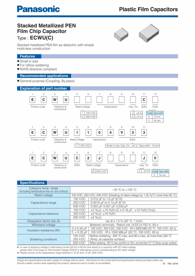
Features● Small in size (Minimum size 1.6 mm × 0.8 mm)● 85 °C, 85 %RH, W.V. × 1.0 for 500 hours● For refl ow soldering● RoHS directive compliant
● Time-constant● Filtering● Oscillation and resonance● Audio circuit
Stacked metallized PPS fi lm as dielectric with simple
mold-less construction
Explanation of part number
Specifi cations
Construction Dimensions
Stacked Metallized PPS Film Chip CapacitorType : ECHU(X)
Category temp. range(Including temperature-rise on unit surface)
– 55 °C to +125 °C
Rated voltage16 V.DC, 50 V.DC
(50 V.DC : 0.12 μF or more : Derating or rated voltage by 1.25 % / °C at more than 105 °C)
Capacitance range16 V.DC 0.00010 μF to 0.10 μF (E12)
50 V.DC 0.00010 μF to 0.22 μF (E12)
Capacitance tolerance ±2 %(G), ±5 %(J)
Dissipation factor (tan d) tan d < 0.6 % (20 °C, 1 kHz)
Withstand voltage Between terminals : Rated volt. (V.DC)×150 %, 60 s
Insulation resistance (IR)16 V.DC : IR > 3000 MΩ (20 °C, 10 V.DC, 60 s)50 V.DC : IR > 3000 MΩ (20 °C, 50 V.DC, 60 s)
Soldering conditions Refl ow soldering : 260 °C max. and 95 sec max. at more than 220 °C (Temp. at capacitor surface)
✽ Please consult us for fl ow soldering✽ In case of applying voltage in alternating current (50 Hz or 60 Hz sine wave) to a capacitor with DC rated voltage, please refer to the page of “Permissible voltage (R.M.S) in alternating current corresponding to DC rated voltage”.
Size code L W H e g
K1 1.6 0.8 0.7 0.35 > 0.4J1 2.0 1.25 0.9 0.45 > 0.6J2 2.0 1.25 1.1 0.45 > 0.6H1 3.2 1.6 0.9 0.65 > 1.0H2 3.2 1.6 1.1 0.65 > 1.0H3 3.2 1.6 1.5 0.65 > 1.0G1 3.2 2.5 1.1 0.65 > 1.0G2 3.2 2.5 1.5 0.65 > 1.0G3 3.2 2.5 2.1 0.65 > 1.0E1 4.8 3.3 1.5 0.80 > 2.0E2 4.8 3.3 2.1 0.80 > 2.0D1 6.0 4.1 1.9 0.80 > 2.0D3 6.0 4.1 2.5 0.80 > 2.0D4 6.0 4.1 2.8 0.80 > 2.0
Unit : mm
Recommended applications
Sep. 201702

Design and specifications are each subject to change without notice. Ask factory for the current technical specifications before purchase and/or use.
Should a safety concern arise regarding this product, please be sure to contact us immediately.
Plastic Film Capacitors
Land
Electrode
C
A
B
Refer to the page of taping specifi cations
● Capacitance tolerance : ±2 %(G), ±5 %(J)
Taping specifi cation for automatic mounting
Rating · Dimensions · Quantity
Recommended for land dimensions
Capacitance(μF)
Rated voltage 16 V.DC Rated voltage 50 V.DC
Part No.Dimensions (mm) Size
codeQ'ty Part No.
Dimensions (mm) Sizecode
Q'tyL W H L W H
0.00010 ECHU1C101◻X5 1.6 0.8 0.7 K1
4000
ECHU1H101◻X5 2.0 1.25 0.9 J1
3000
0.00012 ECHU1C121◻X5 1.6 0.8 0.7 K1 ECHU1H121◻X5 2.0 1.25 0.9 J10.00015 ECHU1C151◻X5 1.6 0.8 0.7 K1 ECHU1H151◻X5 2.0 1.25 0.9 J10.00018 ECHU1C181◻X5 1.6 0.8 0.7 K1 ECHU1H181◻X5 2.0 1.25 0.9 J10.00022 ECHU1C221◻X5 1.6 0.8 0.7 K1 ECHU1H221◻X5 2.0 1.25 0.9 J10.00027 ECHU1C271◻X5 1.6 0.8 0.7 K1 ECHU1H271◻X5 2.0 1.25 0.9 J10.00033 ECHU1C331◻X5 1.6 0.8 0.7 K1 ECHU1H331◻X5 2.0 1.25 0.9 J10.00039 ECHU1C391◻X5 1.6 0.8 0.7 K1 ECHU1H391◻X5 2.0 1.25 0.9 J10.00047 ECHU1C471◻X5 1.6 0.8 0.7 K1 ECHU1H471◻X5 2.0 1.25 0.9 J10.00056 ECHU1C561◻X5 1.6 0.8 0.7 K1 ECHU1H561◻X5 2.0 1.25 0.9 J10.00068 ECHU1C681◻X5 1.6 0.8 0.7 K1 ECHU1H681◻X5 2.0 1.25 0.9 J10.00082 ECHU1C821◻X5 1.6 0.8 0.7 K1 ECHU1H821◻X5 2.0 1.25 0.9 J10.0010 ECHU1C102◻X5 1.6 0.8 0.7 K1 ECHU1H102◻X5 2.0 1.25 0.9 J10.0012 ECHU1C122◻X5 1.6 0.8 0.7 K1 ECHU1H122◻X5 2.0 1.25 0.9 J10.0015 ECHU1C152◻X5 1.6 0.8 0.7 K1 ECHU1H152◻X5 2.0 1.25 0.9 J10.0018 ECHU1C182◻X5 1.6 0.8 0.7 K1 ECHU1H182◻X5 2.0 1.25 0.9 J10.0022 ECHU1C222◻X5 1.6 0.8 0.7 K1 ECHU1H222◻X5 2.0 1.25 0.9 J10.0027 ECHU1C272◻X5 1.6 0.8 0.7 K1 ECHU1H272◻X5 2.0 1.25 0.9 J10.0033 ECHU1C332◻X5 2.0 1.25 0.9 J1
3000
ECHU1H332◻X5 3.2 1.6 0.9 H10.0039 ECHU1C392◻X5 2.0 1.25 0.9 J1 ECHU1H392◻X5 3.2 1.6 0.9 H10.0047 ECHU1C472◻X5 2.0 1.25 0.9 J1 ECHU1H472◻X5 3.2 1.6 0.9 H10.0056 ECHU1C562◻X5 2.0 1.25 0.9 J1 ECHU1H562◻X5 3.2 1.6 0.9 H10.0068 ECHU1C682◻X5 2.0 1.25 0.9 J1 ECHU1H682◻X5 3.2 1.6 0.9 H10.0082 ECHU1C822◻X5 2.0 1.25 1.1 J2 ECHU1H822◻X5 3.2 1.6 1.1 H20.010 ECHU1C103◻X5 2.0 1.25 1.1 J2 ECHU1H103◻X5 3.2 1.6 1.1 H20.012 ECHU1C123◻X5 3.2 1.6 0.9 H1 ECHU1H123◻X5 3.2 2.5 1.1 G1
2000
0.015 ECHU1C153◻X5 3.2 1.6 0.9 H1 ECHU1H153◻X5 3.2 2.5 1.1 G10.018 ECHU1C183◻X5 3.2 1.6 0.9 H1 ECHU1H183◻X5 3.2 2.5 1.5 G20.022 ECHU1C223◻X5 3.2 1.6 0.9 H1 ECHU1H223◻X5 3.2 2.5 1.5 G20.027 ECHU1C273◻X5 3.2 1.6 1.1 H2 ECHU1H273◻X5 3.2 2.5 1.5 G20.033 ECHU1C333◻X5 3.2 1.6 1.1 H2 ECHU1H333◻X5 3.2 2.5 2.1 G30.039 ECHU1C393◻X5 3.2 1.6 1.5 H3
2000
ECHU1H393◻X5 3.2 2.5 2.1 G30.047 ECHU1C473◻X5 3.2 1.6 1.5 H3 ECHU1H473◻X9 4.8 3.3 1.5 E1
3000
0.056 ECHU1C563◻X5 3.2 2.5 1.5 G2 ECHU1H563◻X9 4.8 3.3 1.5 E10.068 ECHU1C683◻X5 3.2 2.5 1.5 G2 ECHU1H683◻X9 4.8 3.3 1.5 E10.082 ECHU1C823◻X5 3.2 2.5 2.1 G3 ECHU1H823◻X9 4.8 3.3 2.1 E20.10 ECHU1C104◻X5 3.2 2.5 2.1 G3 ECHU1H104◻X9 4.8 3.3 2.1 E20.12 ECHU1H124◻X9 6.0 4.1 1.9 D10.15 ECHU1H154◻X9 6.0 4.1 1.9 D10.18 ECHU1H184◻X9 6.0 4.1 2.5 D3
20000.22 ECHU1H224◻X9 6.0 4.1 2.8 D4
Size
code
Land dimensionsRefl ow soldering
A B CK1 0.6 2.0 0.7
J1, J2 0.8 2.4 1.1H1, H2, H3 1.8 3.6 1.4G1, G2, G3 1.8 3.6 2.3
E1, E2 3.0 5.6 3.0D1, D3, D4 4.0 7.0 3.8
✽ ◻ : Capacitance tolerance code
✽ lt is not warrantable that you can mount the capacitor without trouble under all the mounting condition when “Recommender for Land dimensions” is adopted.
Unit : mm
Sep. 201702

Design and specifications are each subject to change without notice. Ask factory for the current technical specifications before purchase and/or use.
Should a safety concern arise regarding this product, please be sure to contact us immediately.
Plastic Film Capacitors
1 2 3 4 5 6 7 8 9 10 11
E C H U 1 C
Product code Dielectric &construction
Rated voltage Cap. Tol. SuffixSuffixCapacitance
Code
9
V
Tape width
12 mm
16 mm
G
J
±2 %
±5 %
1 100 V.DC
Features● Small in size● Low loss and excellent frequency characteristics● For refl ow soldering● RoHS directive compliant
● Time-constant● Filtering● Oscillation and resonance● Resonance circuit for LCD backlight inverter unit
Stacked metallized PPS fi lm as dielectric with simple
mold-less construction
Stacked Metallized PPS Film Chip CapacitorType : ECHU(C)
Category temp. range(Including temperature-rise on unit surface)
– 55 °C to +105 °C
Rated voltage 100 V.DC
Capacitance range 0.010 µF to 0.22 µF (E12)
Capacitance tolerance ±2 %(G), ±5 %(J)
Dissipation factor (tan d) tan d < 0.6 % (20 °C, 1 kHz)
Withstand voltage Between terminals : Rated volt. (V.DC)×150 %, 60 s
Insulation resistance (IR) IR > 3000 MΩ (20 °C, 100 V.DC, 60 s)
Soldering conditionsRefl ow soldering : 260 °C max. and 95 sec max. at more than 220 °C
(Temp. at capacitor surface)
✽ In case of applying voltage in alternating current (50 Hz or 60 Hz sine wave) to a capacitor with DC rated voltage, please refer to the page of “Permissible voltage (R.M.S) in alternating current corresponding to DC rated voltage”.
Explanation of part number
Specifi cations
Recommended applications
Feb. 201601

Design and specifications are each subject to change without notice. Ask factory for the current technical specifications before purchase and/or use.
Should a safety concern arise regarding this product, please be sure to contact us immediately.
Plastic Film Capacitors
Element(Stacked)
Outerelectrode
L±0.2 W±0.3
H±
0.2
0.35±0.20 0.35±0.20
(±0.4) ✽ (±0.4) ✽
(±0
.3)
✽
✽ To be applied only for size code Z, Y
Land
Electrode
C
A
B
Capacitance(µF)
Rated voltage 100 V.DC
Part No.Dimensions (mm) Size
codeQ'ty
L W H
0.010 ECHU1103◻C9 4.8 3.3 1.4 E1
30000.012 ECHU1123◻C9 4.8 3.3 1.4 E1
0.015 ECHU1153◻C9 4.8 3.3 2.0 E2
0.018 ECHU1183◻C9 4.8 3.3 2.0 E2
0.022 ECHU1223◻C9 4.8 3.3 2.4 E3a2000
0.027 ECHU1273◻C9 4.8 3.3 2.8 E3
0.033 ECHU1333◻C9 6.0 4.1 1.8 D13000
0.039 ECHU1393◻C9 6.0 4.1 2.0 D2
0.047 ECHU1473◻C9 6.0 4.1 2.4 D3
20000.056 ECHU1563◻C9 6.0 4.1 2.8 D4
0.068 ECHU1683◻C9 6.0 4.1 3.2 D5
0.082 ECHU1823◻C9 7.1 5.0 2.8 Z
15000.10 ECHU1104◻C9 7.1 5.0 3.0 Z
0.12 ECHU1124◻C9 7.1 5.0 3.4 Z
0.15 ECHU1154◻CV 7.1 6.3 3.4 Y
10000.18 ECHU1184◻CV 7.1 6.3 4.0 Y
0.22 ECHU1224◻CV 7.1 6.3 4.8 Y
Sizecode
L W H
E1 4.8 3.3 1.4E2 4.8 3.3 2.0E3a 4.8 3.3 2.4E3 4.8 3.3 2.8D1 6.0 4.1 1.8D2 6.0 4.1 2.0D3 6.0 4.1 2.4D4 6.0 4.1 2.8D5 6.0 4.1 3.2Z 7.1 5.0 ✽Y 7.1 6.3 ✽
Size code
Land dimensions
Refl ow soldering
A B C
E1, E2, E3a, E3 2.6 6.6 3.0
D1, D2, D3, D4, D5 3.8 7.8 3.8
Z 4.5 9.0 4.6
Y 4.5 9.0 5.7
✽ ◻ : Capacitance tolerance code
✽ lt is not warrantable that you can mount the capacitor without trouble under all the mounting condition when “Recommender for Land dimensions” is adopted.
Unit : mm
Unit : mm
✽ Refer to the column “ Rating, Dimensions&Quantity”
Construction Dimensions
Refer to the page of taping specifi cations
● Capacitance tolerance : ±2 %(G), ±5 %(J)
Taping specifi cation for automatic mounting
Rating · Dimensions · Quantity
Recommended for land dimensions
Feb. 201601

Design and specifications are each subject to change without notice. Ask factory for the current technical specifications before purchase and/or use.
Should a safety concern arise regarding this product, please be sure to contact us immediately.
Plastic Film Capacitors
1 2 3 4 5 6 7 8 9 10 11
E C W U 1 5J X
Product code Dielectric &construction
Cap. Tol. SuffixRated voltage Capacitance Suffix
Code
5
Tape width
8 mm
J ±5 %1 100 V.DC
Element(Stacked)
Outerelectrode
L±0.2 W±0.2
H±
0.2
e±0.30 e±0.30g
Specifi cations
● Small in size (minimum size 3.2 mm × 1.6 mm)● 85 °C, 85 %RH, W.V. × 1.0 for 500 hours● For refl ow soldering● RoHS directive compliant
● General purpose (Coupling, By-pass)
Stacked metallized PEN fi lm as dielectric with simple
mold-less construction
Features
Stacked Metallized PEN Film Chip CapacitorType : ECWU(X)
Category temp. range(Including temperature-rise on unit surface)
– 55 °C to +105 °C
Rated voltage 100 V.DC
Capacitance range 0.0010 μF to 0.010 μF (E12)
Capacitance tolerance ±5 %(J)
Dissipation factor (tan d) tan d < 1.0 % ( 20 °C, 1 kHz )
Withstand voltage Between terminals : Rated volt. (V.DC)×150 %, 60 s
Insulation resistance (IR) IR > 3000 MΩ (20 °C, 100 V.DC, 60 s)
Soldering conditionsRefl ow soldering : 250 °C max. and 60 s max. at more than 220 °C
(Temp. at capacitor surface)
✽ In case of applying voltage in alternating current (50 Hz or 60 Hz sine wave) to a capacitor with DC rated voltage, please refer to the page of “Permissible voltage (R.M.S) in alternating current corresponding to DC rated voltage”.
Sizecode
L W H e g
H2 3.2 1.6 1.1 0.65 > 1.0H3 3.2 1.6 1.5 0.65 > 1.0G2 3.2 2.5 1.5 0.65 > 1.0G3 3.2 2.5 2.1 0.65 > 1.0
Unit : mm
Explanation of part number
Construction Dimensions
Recommended applications
Feb. 201601

Design and specifications are each subject to change without notice. Ask factory for the current technical specifications before purchase and/or use.
Should a safety concern arise regarding this product, please be sure to contact us immediately.
Plastic Film Capacitors
Capacitance(μF)
Rated voltage 100 V.DC
Part No.Dimensions (mm) Size
codeQ'ty
L W H
0.0010 ECWU1102JX5 3.2 1.6 1.1 H2
3000
0.0012 ECWU1122JX5 3.2 1.6 1.1 H2
0.0015 ECWU1152JX5 3.2 1.6 1.1 H2
0.0018 ECWU1182JX5 3.2 1.6 1.1 H2
0.0022 ECWU1222JX5 3.2 1.6 1.1 H2
0.0027 ECWU1272JX5 3.2 1.6 1.1 H2
0.0033 ECWU1332JX5 3.2 1.6 1.5 H3
2000
0.0039 ECWU1392JX5 3.2 1.6 1.5 H3
0.0047 ECWU1472JX5 3.2 1.6 1.5 H3
0.0056 ECWU1562JX5 3.2 2.5 1.5 G2
0.0068 ECWU1682JX5 3.2 2.5 1.5 G2
0.0082 ECWU1822JX5 3.2 2.5 2.1 G3
0.010 ECWU1103JX5 3.2 2.5 2.1 G3
cap. > 0.012 μF : Please use 100 V.DC rating of ECWU(C)
Land
Electrode
C
A
B
Size code
Land dimensions
Refl ow soldering
A B C
H2, H3 1.8 3.6 1.4
G2, G3 1.8 3.6 2.3
✽ lt is not warrantable that you can mount the capacitor without trouble under all the mounting condition when “Recommender for Land dimensions” is adopted.
Unit : mm
Refer to the page of taping specifi cations
● Capacitance tolerance : ±5 %(J)
Taping specifi cation for automatic mounting
Rating · Dimensions · Quantity
Recommended for land dimensions
Feb. 201601
Design and specifications are each subject to change without notice. Ask factory for the current technical specifications before purchase and/or use.
Should a safety concern arise regarding this product, please be sure to contact us immediately.
Plastic Film Capacitors
1 2 3 4 5 6 7 8 9 10 11
E C W U
12
C
Product code Dielectric &construction
Rated voltage Cap. Tol. SuffixSuffixCapacitance
Code
9
V
Tape width
12 mm
16 mm
J
K
±5 %
±10 %2 250 V.DC
1 100 V.DC
1 2 3 4 5 6 7 8 9 10 11
E C W U 1 1 0 4 V 33
Product code Dielectric &construction
Rated voltage Capacitance Suffix
1 100 V.DC Small in size, Cap. Tol. : ±5 %, Tape width : 12 mm
1 2 3 4 5 6 7 8 9 10 11
E C W U C 2 J
12
J V
Product code Dielectric &construction
Rated voltage Cap. Tol. SuffixSuffix Capacitance
Code
V
Tape width
16 mm
J ±5 %2J 630 V.DC
Stacked metallized PEN fi lm as dielectric with simplemold-less construction
Stacked Metallized PEN Film Chip CapacitorType : ECWU(C)
Category temp. range(Including temperature-rise on unit surface)
– 55 °C to +125 °C
Rated voltage 100 V.DC, 250 V.DC, 630 V.DC (Derating of rated voltage by 1.25 %/°C more than 85 °C)
Capacitance range
100 V.DC 0.012 μF to 1.0 μF (E12)
250 V.DC 0.0010 μF to 0.12 μF (E12)
630 V.DC 0.022 μF, 0.027 μF, 0.033 μF
Capacitance tolerance
100 V.DC ±5 %(J), ±10 %(K) (C > 0.18 μF : ±10 %(K) Only)
250 V.DC ±5 %(J), ±10 %(K)
630 V.DC ±5 %(J)
Dissipation factor (tan d) tan d < 1.0 % (20 °C, 1 kHz)
Withstand voltage Between terminals : Rated volt. (V.DC)×150 %, 60 s
Insulation resistance (IR)C < 0.33 μF 100 V.DC, 250 V.DC, 630 V.DC : IR > 3000 MΩ (20 °C, 100 V.DC, 60 s)
C > 0.33 μF 100 V.DC : IR > 1000 MΩ∙μF (20 °C, 100 V.DC, 60 s)
Soldering conditions100 V.DC250 V.DC
Refl ow soldering : 250 °C max. and 60 s max. at more than 220 °C(Temp. at capacitor surface)
630 V.DC Refl ow soldering : 250 °C max. and 60 s to 150 s. at more than 217 °C (Temp. at cap. surface)
✽ In case of applying voltage in alternating current (50 Hz or 60 Hz sine wave) to a capacitor with DC rated voltage,
please refer to the page of “Permissible voltage (R.M.S) in alternating current corresponding to DC rated voltage”.
✽ Please consult us for capacitance range between 0.15 μF and 1.0 μF. (250 V.DC)
● Small in size● For refl ow soldering● RoHS directive compliant
● General purpose (Coupling, By-pass)
Features
Recommended applications
Explanation of part number
Specifi cations
Feb. 201601

Design and specifications are each subject to change without notice. Ask factory for the current technical specifications before purchase and/or use.
Should a safety concern arise regarding this product, please be sure to contact us immediately.
Plastic Film Capacitors
Element(Stacked)
Outerelectrode 0.35±0.20 0.35±0.20
H±
0.2
(±
0.3
)✽
✽✽
✽ To be applied only for size code Z, X ✽✽ To be applied only for size code V ✽✽✽ To be applied only for size code B, Z, X, V
✽✽✽
(±0.5)(±0.4)L±0.2
✽✽✽(±0.4)W±0.3
Capacitance(μF)
Rated voltage 100 V.DC Rated voltage 250 V.DC
Part No.Dimensions (mm) Size
codeQ'ty Part No.
Dimensions (mm) Sizecode
Q'tyL W H L W H
0.0010
Please use 0.001 μF to 0.01 μF
rating ECWU(X)
ECWU2102◻C9 4.8 3.3 1.4 E1
3000
0.0012 ECWU2122◻C9 4.8 3.3 1.4 E10.0015 ECWU2152◻C9 4.8 3.3 1.4 E10.0018 ECWU2182◻C9 4.8 3.3 1.4 E10.0022 ECWU2222◻C9 4.8 3.3 1.4 E10.0027 ECWU2272◻C9 4.8 3.3 1.4 E10.0033 ECWU2332◻C9 4.8 3.3 1.4 E10.0039 ECWU2392◻C9 4.8 3.3 1.4 E10.0047 ECWU2472◻C9 4.8 3.3 1.4 E10.0056 ECWU2562◻C9 4.8 3.3 1.4 E10.0068 ECWU2682◻C9 4.8 3.3 1.4 E10.0082 ECWU2822◻C9 4.8 3.3 1.4 E10.010 ECWU2103◻C9 4.8 3.3 1.4 E10.012 ECWU1123◻C9 4.8 3.3 1.4 E1
3000
ECWU2123◻C9 4.8 3.3 1.4 E10.015 ECWU1153◻C9 4.8 3.3 1.4 E1 ECWU2153◻C9 4.8 3.3 1.4 E10.018 ECWU1183◻C9 4.8 3.3 1.4 E1 ECWU2183◻C9 4.8 3.3 2.0 E20.022 ECWU1223◻C9 4.8 3.3 1.4 E1 ECWU2223◻C9 4.8 3.3 2.0 E20.027 ECWU1273◻C9 4.8 3.3 1.4 E1 ECWU2273◻C9 4.8 3.3 2.4 E3a
20000.033 ECWU1333◻C9 4.8 3.3 1.4 E1 ECWU2333◻C9 4.8 3.3 2.8 E30.039 ECWU1393◻C9 4.8 3.3 1.4 E1 ECWU2393◻C9 6.0 4.1 2.0 D2 30000.047 ECWU1473◻C9 4.8 3.3 2.0 E2 ECWU2473◻C9 6.0 4.1 2.4 D3
20000.056 ECWU1563◻C9 4.8 3.3 2.0 E2 ECWU2563◻C9 6.0 4.1 2.8 D40.068 ECWU1683◻C9 4.8 3.3 2.4 E3a
2000ECWU2683◻C9 6.0 4.1 3.2 D5
0.082 ECWU1823◻C9 4.8 3.3 2.8 E3 ECWU2823◻C9 6.0 5.0 3.2 B
15000.10ECWU1104◻C9 6.0 4.1 1.8 D1 3000
ECWU2104◻C9 6.0 5.0 3.8 BECWU1104V33 4.8 3.3 2.8 E3
20000.12 ECWU1124◻C9 6.0 4.1 2.4 D3 ECWU2124◻C9 6.0 5.0 4.5 B0.15 ECWU1154◻C9 6.0 4.1 2.8 D40.18 ECWU1184KC9 7.1 5.0 2.0 Z
15000.22 ECWU1224KC9 7.1 5.0 2.4 Z0.27 ECWU1274KC9 7.1 5.0 2.9 Z0.33 ECWU1334KC9 7.1 5.0 3.5 Z0.39 ECWU1394KCV 7.7 5.5 3.4 x
1000
0.47 ECWU1474KCV 7.7 5.5 4.0 x0.56 ECWU1564KCV 9.8 6.3 3.0 V0.68 ECWU1684KCV 9.8 6.3 3.6 V0.82 ECWU1824KCV 9.8 6.3 4.3 V
1.0 ECWU1105KCV 9.8 6.3 5.1 V
Size code L W H
E1 4.8 3.3 1.4
E2 4.8 3.3 2.0
E3a 4.8 3.3 2.4
E3 4.8 3.3 2.8
D1 6.0 4.1 1.8
D2 6.0 4.1 2.0
D3 6.0 4.1 2.4
D4 6.0 4.1 2.8
D5 6.0 4.1 3.2
B 6.0 5.0
✽Z 7.1 5.0
X 7.7 5.5
V 9.8 6.3
✽ ◻ : Capacitance tolerance
Unit : mm
✽ Refer to the column “Rating, Dimensions & Quantity”.
Refer to the page of taping specifi cations
● Capacitance tolerance : ±5 %(J), ±10 %(K)
Taping specifi cation for automatic mounting
Rating · Dimensions · Quantity
Construction Dimensions
Feb. 201601

Design and specifications are each subject to change without notice. Ask factory for the current technical specifications before purchase and/or use.
Should a safety concern arise regarding this product, please be sure to contact us immediately.
Plastic Film Capacitors
Land
ElectrodeC
A
B
● Capacitance tolerance : ±5 %(J)
Capacitance(μF)
Rated voltage 630 V.DC
Part No.Dimensions (mm) Size
codeQ'ty
L W H
0.022 ECWUC2J223JV 7.1 6.3 3.6 Y
10000.027 ECWUC2J273JV 7.1 6.3 4.1 Y
0.033 ECWUC2J333JV 7.1 6.3 5.1 Y
Size code
Land dimensions
Refl ow soldering
A B C
E1, E2, E3a, E3 2.6 6.6 3.0
D1, D2, D3, D4, D5 3.8 7.8 3.8
B 3.8 7.8 4.6
Z 4.5 9.0 4.6
Y 4.5 9.0 5.7
X 5.1 9.7 5.0
V 7.2 11.9 5.7
✽ lt is not warrantable that you can mount the capacitor without trouble under all the mounting condition when “Recommender for Land dimensions” is adopted.
Unit : mm
Recommended for land dimensions
Rating · Dimensions · Quantity
Feb. 201601

Design and specifications are each subject to change without notice. Ask factory for the current technical specifications before purchase and/or use.
Should a safety concern arise regarding this product, please be sure to contact us immediately.
Plastic Film Capacitors
1 2 3 4 5 6 7 8 9 10 11
E C W U 2 6V 1
Product code Dielectric &construction
Rated voltage Capacitance Suffix
2 250 V.DCV16
for xDSL, Withstand voltage : 400 V.DC
Cap.tol : ±5 %
Element(Stacked)
Outerelectrode
H±
0.2
(±0.3
) ✽
0.35±0.20 0.35±0.20
✽ To be applied only for size code B
L±0.2(±0.4)*W±0.3
● Small in size● For refl ow soldering● RoHS directive compliant
● DC Blocking for xDSL
Features
Recommended applications
Explanation of part number
Stacked metallized PEN fi lm dielectric with simple moldless
construction
Stacked Metallized PEN Film Chip CapacitorType : ECWU(V16)
Category temp. range(Including temperature-rise on unit surface)
– 55 °C to +85 °C
Rated voltage 250 V.DC
Capacitance range 0.0010 µF to 0.12 µF (E12)
Capacitance tolerance ±5 %(J)
Dissipation factor (tan d) tan d < 1.0 % ( 20 °C, 1 kHz )
Withstand voltage Between terminals : 400 V.DC, 60 s
Insulation resistance (IR) IR > 3000 MΩ (20 °C, 100 V.DC, 60 s)
Soldering conditionsRefl ow soldering : 250 °C max. and 60 s max. at more than 220 °C
(Temp. at capacitor surface)
✽ Application of this capacitor is limited to DC Blocking for xDSL, such as ADSL.
✽ Please consult us for 400 V.DC rating product.
Size code L W HE1 4.8 3.3 1.4E2 4.8 3.3 2.0E3a 4.8 3.3 2.4E3 4.8 3.3 2.8D2 6.0 4.1 2.0D3 6.0 4.1 2.4D4 6.0 4.1 2.8D5 6.0 4.1 3.2B 6.0 5.0 ✽
Unit : mm
✽ Refer to the column “Rating, Dimensions & Quantity”.
Specifi cations
Construction Dimensions
Sep. 201702

Design and specifications are each subject to change without notice. Ask factory for the current technical specifications before purchase and/or use.
Should a safety concern arise regarding this product, please be sure to contact us immediately.
Plastic Film Capacitors
Land
Electrode
C
A
B
Refer to the page of taping specifi cations
● Capacitance tolerance : ±5 %(J)
Capacitance(µF)
Rated voltage 250 V.DC
Part No.Dimensions (mm) Size
codeQ'ty
L W H
0.0010 ECWU2102V16 4.8 3.3 1.4 E1
3000
0.0012 ECWU2122V16 4.8 3.3 1.4 E1
0.0015 ECWU2152V16 4.8 3.3 1.4 E1
0.0018 ECWU2182V16 4.8 3.3 1.4 E1
0.0022 ECWU2222V16 4.8 3.3 1.4 E1
0.0027 ECWU2272V16 4.8 3.3 1.4 E1
0.0033 ECWU2332V16 4.8 3.3 1.4 E1
0.0039 ECWU2392V16 4.8 3.3 1.4 E1
0.0047 ECWU2472V16 4.8 3.3 1.4 E1
0.0056 ECWU2562V16 4.8 3.3 1.4 E1
0.0068 ECWU2682V16 4.8 3.3 1.4 E1
0.0082 ECWU2822V16 4.8 3.3 1.4 E1
0.010 ECWU2103V16 4.8 3.3 1.4 E1
0.012 ECWU2123V16 4.8 3.3 1.4 E1
0.015 ECWU2153V16 4.8 3.3 1.4 E1
0.018 ECWU2183V16 4.8 3.3 2.0 E2
0.022 ECWU2223V16 4.8 3.3 2.0 E2
0.027 ECWU2273V16 4.8 3.3 2.4 E3a2000
0.033 ECWU2333V16 4.8 3.3 2.8 E3
0.039 ECWU2393V16 6.0 4.1 2.0 D2 3000
0.047 ECWU2473V16 6.0 4.1 2.4 D3
20000.056 ECWU2563V16 6.0 4.1 2.8 D4
0.068 ECWU2683V16 6.0 4.1 3.2 D5
0.082 ECWU2823V16 6.0 5.0 3.2 B
15000.10 ECWU2104V16 6.0 5.0 3.8 B
0.12 ECWU2124V16 6.0 5.0 4.5 B
Size code
Land dimensions
Refl ow soldering
A B C
E1, E2, E3a, E3 2.6 6.6 3.0
D2, D3, D4, D5 3.8 7.8 3.8
B 3.8 7.8 4.6
✽ lt is not warrantable that you can mount the capacitor without trouble under all the mounting condition when “Recommender for Land dimensions” is adopted.
Unit : mm
Taping specifi cation for automatic mounting
Rating · Dimensions · Quantity
Recommended for land dimensions
Sep. 201702

Design and specifications are each subject to change without notice. Ask factory for the current technical specifications before purchase and/or use.
Should a safety concern arise regarding this product, please be sure to contact us immediately.
Plastic Film Capacitors
1 2 3 4 5 6 7 8 9 11 12
E C P U 1 C 5A
Product code Dielectric &construction
SuffixRated voltage Capacitance Suffix
Code
5
Tape width
8 mm
Cap. Tol.
1C 16 V.DC
10
M
Element(Stacked)
Outerelectrode
L±0.2 W±0.20
H±
0.2
e±0.30(±0.25)
e±0.30(±0.25)
g
✽ ✽
✽ To be applied only for size code J1
● Low ESR● Max. capacitance values 1.0 μF● Smallest package size in fi lm capacitors 3225/1.0 μF● For refl ow soldering● RoHS directive compliant
● Noise suppressor● Audio circuit
Stacked dielectric and inner electrode with simple
mold - less construction
Features
Stacked Metallized Plastic Film Chip CapacitorType : ECPU(A)
Category temp. range(Including temperature-rise on unit surface)
– 40 °C to +85 °C
Rated voltage 16 V.DC
Capacitance range 0.10 μF to 1.0 μF (E6)
Capacitance tolerance ±20 %(M)
Dissipation factor (tan d) tan d < 1.5 % ( 20 °C, 1 kHz )
Withstand voltage Between terminals : Rated volt (V.DC)×150 %, 60 s
Insulation resistance (IR)C < 0.33 μF : IR > 1000 MΩ (20 °C, 10 V.DC, 60 s)C > 0.33 μF : IR > 300 MΩ ∙ μF (20 °C, 10 V.DC, 60 s)
Soldering conditionsRefl ow soldering : 240 °C max. and 30 sec max. at more than 220 °C
(Temp. at capacitor surface)
✽ In case of applying voltage in alternating current (50 Hz or 60 Hz sine wave) to a capacitor with DC rated voltage,
please refer to the page of “Permissible voltage (R.M.S) in alternating current corresponding to DC rated voltage”.
Size code
L W H e g
J1 2.0 1.25 1.0 0.45 > 0.6H1 3.2 1.6 0.8 0.65 > 1.0H2 3.2 1.6 1.0 0.65 > 1.0H3 3.2 1.6 1.4 0.65 > 1.0G2 3.2 2.5 1.4 0.65 > 1.0
Unit : mm
Construction Dimensions
Recommended applications
Explanation of part number
Specifi cations
Sep. 201702

Design and specifications are each subject to change without notice. Ask factory for the current technical specifications before purchase and/or use.
Should a safety concern arise regarding this product, please be sure to contact us immediately.
Plastic Film Capacitors
Land
Electrode
C
A
B
Refer to the page of taping specifi cations
Taping specifi cation for automatic mounting
Capacitance(μF)
Rated voltage 16 V.DC
Part No.Dimensions (mm)
Size code Q'tyL W H
0.10 ECPU1C104MA5 2.0 1.25 1.0 J1
30000.15 ECPU1C154MA5 3.2 1.6 0.8 H1
0.22 ECPU1C224MA5 3.2 1.6 0.8 H1
0.33 ECPU1C334MA5 3.2 1.6 1.0 H2
0.47 ECPU1C474MA5 3.2 1.6 1.4 H3
20000.68 ECPU1C684MA5 3.2 1.6 1.4 H3
1.0 ECPU1C105MA5 3.2 2.5 1.4 G2
Size code
Land dimensions
Refl ow soldering
A B C
J1 0.8 2.4 1.1
H1 1.8 3.6 1.4
H2 1.8 3.6 1.4
H3 1.8 3.6 1.4
G2 1.8 3.6 2.3
✽ lt is not warrantable that you can mount the capacitor without trouble under all the mounting condition when “Recommender for Land dimensions” is adopted.
Unit : mm
Recommended for land dimensions
Rating · Dimensions · Quantity
Sep. 201702

Design and specifications are each subject to change without notice. Ask factory for the current technical specifications before purchase and/or use.
Should a safety concern arise regarding this product, please be sure to contact us immediately.
Plastic Film Capacitors
1 2 3 4 5 6 7 8 9 11 12
E C Q E F
Product code Dielectric &construction
SuffixRated voltage Capacitance SuffixCap. Tol.
10
Code
Blank
B
Z
3
6
Lead Form
Straight
Crimped lead
Cut lead
Crimped taping (Ammo)
Crimped taping (Ammo)
1 100 V.DC
2 250 V.DC
4 400 V.DC
6 630 V.DC
10 1000 V.DC
12 1250 V.DC
1A 125 V.AC
2A 250 V.AC
J ±5 %
K ±10 %
1 2 3 4 5 6 7 8 9 11 12
E C Q E F
Product code Dielectric &construction
Cap. Tol.Rated voltage Capacitance SuffixSuffix
10
R
● Self-healing property● Excellent electrical characteristics● Flame retardant epoxy resin coating● RoHS directive compliant
● General purpose usage ✽ Please contact us when applications are CDI , ignitor etc.
● Odd size taping
Non-inductive construction using metallized Polyester
fi lm with fl ame retardant epoxy resin coating
Metallized Polyester Film CapacitorType : ECQE(F)
Features
Recommended applications
Explanation of part number
Sep. 201702
Design and specifications are each subject to change without notice. Ask factory for the current technical specifications before purchase and/or use.
Should a safety concern arise regarding this product, please be sure to contact us immediately.
Plastic Film Capacitors
L max.
Marking
G m
ax.
H m
ax.
20 m
in.
L max.
H m
ax.
F±1.0
S±0.8
4.5
±0.5
Marking
T max.
fd±0.05
Copper-clad
steel-wire
Straight Crimped lead (Suffix B)
Type B
L max.
S±0.8
Marking
H m
ax.
Type D 4.5
±0.5
Cut lead (Suffix Z)
Marking
4.5
±0.5
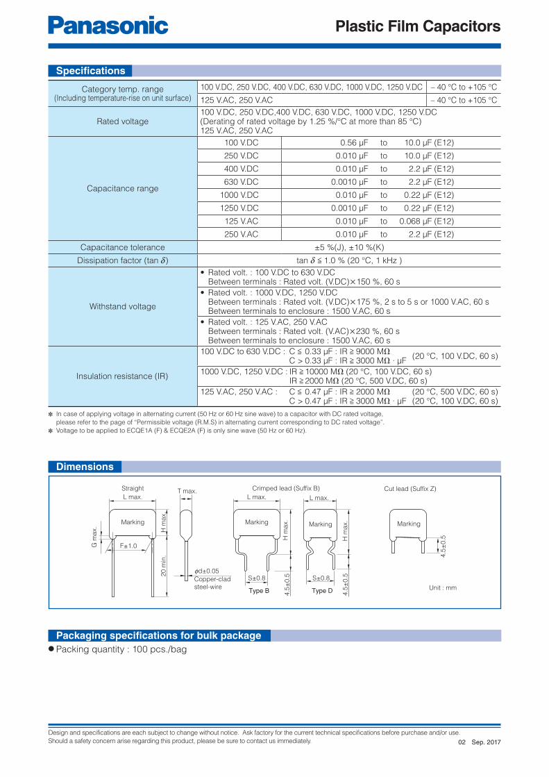
Category temp. range(Including temperature-rise on unit surface)
100 V.DC, 250 V.DC, 400 V.DC, 630 V.DC, 1000 V.DC, 1250 V.DC – 40 °C to +105 °C
125 V.AC, 250 V.AC – 40 °C to +105 °C
Rated voltage100 V.DC, 250 V.DC,400 V.DC, 630 V.DC, 1000 V.DC, 1250 V.DC(Derating of rated voltage by 1.25 %/°C at more than 85 °C)125 V.AC, 250 V.AC
Capacitance range
100 V.DC 0.56 μF to 10.0 μF (E12)
250 V.DC 0.010 μF to 10.0 μF (E12)
400 V.DC 0.010 μF to 2.2 μF (E12)
630 V.DC 0.0010 μF to 2.2 μF (E12)
1000 V.DC 0.010 μF to 0.22 μF (E12)
1250 V.DC 0.0010 μF to 0.22 μF (E12)
125 V.AC 0.010 μF to 0.068 μF (E12)
250 V.AC 0.010 μF to 2.2 μF (E12)
Capacitance tolerance ±5 %(J), ±10 %(K)
Dissipation factor (tan d) tan d < 1.0 % (20 °C, 1 kHz )
Withstand voltage
• Rated volt. : 100 V.DC to 630 V.DC Between terminals : Rated volt. (V.DC)×150 %, 60 s
• Rated volt. : 1000 V.DC, 1250 V.DC Between terminals : Rated volt. (V.DC)×175 %, 2 s to 5 s or 1000 V.AC, 60 s Between terminals to enclosure : 1500 V.AC, 60 s
• Rated volt. : 125 V.AC, 250 V.AC Between terminals : Rated volt. (V.AC)×230 %, 60 s Between terminals to enclosure : 1500 V.AC, 60 s
Insulation resistance (IR)
100 V.DC to 630 V.DC : C < 0.33 μF : IR > 9000 MΩ (20 °C, 100 V.DC, 60 s)
C > 0.33 μF : IR > 3000 MΩ ∙ μF
1000 V.DC, 1250 V.DC : IR > 10000 MΩ (20 °C, 100 V.DC, 60 s) IR > 2000 MΩ (20 °C, 500 V.DC, 60 s)
125 V.AC, 250 V.AC : C < 0.47 μF : IR > 2000 MΩ (20 °C, 500 V.DC, 60 s) C > 0.47 μF : IR > 3000 MΩ ∙ μF (20 °C, 100 V.DC, 60 s)
✽ In case of applying voltage in alternating current (50 Hz or 60 Hz sine wave) to a capacitor with DC rated voltage,
please refer to the page of “Permissible voltage (R.M.S) in alternating current corresponding to DC rated voltage”.
✽ Voltage to be applied to ECQE1A (F) & ECQE2A (F) is only sine wave (50 Hz or 60 Hz).
Specifi cations
Unit : mm
● Packing quantity : 100 pcs./bag
Packaging specifi cations for bulk package
Dimensions
Sep. 201702

Design and specifications are each subject to change without notice. Ask factory for the current technical specifications before purchase and/or use.
Should a safety concern arise regarding this product, please be sure to contact us immediately.
Plastic Film Capacitors
P
FH1
H0
P0
FH1
H0
P0
P
F
P
P0
H1
H0
F
P
P0
H0
H1
F
P
P0
H1
H0
P
F
H1
H0
P0
TypeRated
voltageCapacitance range
(μF)Taping style
Packing suffi xAD AS AB B C D E
ECQE(F)
100 V.DC
0.56 to 0.68 ◯ Ammo ( ) F30.82 to 1.0 ◯ Ammo ( ) F31.2 to 3.3 ◯ Ammo ( ) F31.2 to 3.3 ◯ Ammo R( ) F
250 V.DC
0.010 to 0.27 ◯ Ammo ( ) F30.33 ◯ Ammo ( ) F3
0.39 to 1.5 ◯ Ammo ( ) F30.010 to 0.33 ◯ Ammo R( ) F0.39 to 1.5 ◯ Ammo R( ) F
400 V.DC
0.010 to 0.10 ◯ Ammo ( ) F30.12 to 0.47 ◯ Ammo ( ) F30.010 to 0.10 ◯ Ammo R( ) F0.12 to 0.47 ◯ Ammo R( ) F
630 V.DC
0.0010 to 0.033 ◯ Ammo ( ) F30.039 to 0.047 ◯ Ammo ( ) F30.056 to 0.22 ◯ Ammo ( ) F30.001 to 0.047 ◯ Ammo R( ) F0.056 to 0.22 ◯ Ammo R( ) F
1000 V.DC 0.010 to 0.10 ◯ Ammo R( ) F1250 V.DC 0.0010 to 0.022 ◯ Ammo R( ) F
125 V.AC0.010 to 0.068 ◯ Ammo ( ) F60.010 to 0.068 ◯ Ammo R( ) F
250 V.AC0.010 to 0.033 ◯ Ammo ( ) F60.010 to 0.047 ◯ Ammo R( ) F0.056 to 0.22 ◯ Ammo R( ) F
✽ Refer to the page of taping specifications.
✽ See the column “Rating · Dimensions · Quantity” for packing quantity
● Taping style
● Packaging specifi cations ● Lead spacing
Style AD Style AB Style B
Style C Style D Style E
Taping specifi cations for automatic insertion
Style Lead spacing
AD 5.0 mm
AB 5.0 mm
B 5.0 mm
C 5.0 mm
D 7.5 mm
E 7.5 mm
Sep. 201702

Design and specifications are each subject to change without notice. Ask factory for the current technical specifications before purchase and/or use.
Should a safety concern arise regarding this product, please be sure to contact us immediately.
Plastic Film Capacitors
Part No.Cap.(μF)
Dimensions (mm) Min. order Q'ty
L max. T max.H max. F S G max. fd
Taping BulkStraight Crimped lead Straight Crimped lead Straight Standard 5 mm Odd size 5 mm Odd size 7.5 mm Straight ·Crimped lead
ECQE1564◻F( ) 0.56 12.0 5.5 10.9 15.9 10.0 10.0 1.0 0.6500 –
–
500
ECQE1684◻F( ) 0.68 12.0 6.0 11.9 16.9 10.0 10.0 1.0 0.6ECQE1824◻F( ) 0.82 12.0 6.0 13.5 18.5 10.0 10.0 1.0 0.6
–
1,000ECQE1105◻F( ) 1.0 12.0 6.7 14.0 19.0 10.0 10.0 1.0 0.6ECQE1125◻F( ) 1.2 18.5 5.5 12.8 17.8 15.0 10.0 1.0 0.6
500
600ECQE1155◻F( ) 1.5 18.5 6.0 13.4 18.4 15.0 10.0 1.0 0.8
500ECQE1185◻F( ) 1.8 18.5 6.5 14.4 19.4 15.0 10.0 1.0 0.8ECQE1225◻F( ) 2.2 18.5 7.0 15.0 20.0 15.0 10.0 1.0 0.8ECQE1275◻F( ) 2.7 18.5 8.0 15.8 20.8 15.0 10.0 1.0 0.8
400ECQE1335◻F( ) 3.3 18.5 8.5 16.5 21.5 15.0 10.0 1.0 0.8 400ECQE1395◻F( ) 3.9 26.0 7.0 16.4 21.4 22.5 15.0 1.0 0.8
– –
ECQE1475◻F( ) 4.7 26.0 7.5 17.0 22.0 22.5 15.0 1.0 0.8ECQE1565◻F( ) 5.6 26.0 8.3 17.5 22.5 22.5 15.0 1.0 0.8ECQE1685◻F( ) 6.8 26.0 9.0 18.5 23.5 22.5 15.0 1.0 0.8ECQE1825◻F( ) 8.2 26.0 10.0 20.0 25.0 22.5 15.0 1.5 0.8ECQE1106◻F( ) 10.0 26.0 11.5 21.0 26.0 22.5 15.0 1.5 0.8
Part No.Cap.(μF)
Dimensions (mm) Min. order Q'ty
L max. T max.H max. F S G max. fd
Taping BulkStraight Crimped lead Straight Crimped lead Straight Standard 5 mm Odd size 5 mm Odd size 7.5 mm Straight Crimped lead
ECQE2103◻F( ) 0.010 10.3 4.3 7.4 12.4 7.5 7.5 1.0 0.6
1000
–1000
500500
ECQE2123◻F( ) 0.012 10.3 4.4 7.5 12.5 7.5 7.5 1.0 0.6ECQE2153◻F( ) 0.015 10.3 4.4 7.5 12.5 7.5 7.5 1.0 0.6ECQE2183◻F( ) 0.018 10.3 4.4 7.5 12.5 7.5 7.5 1.0 0.6ECQE2223◻F( ) 0.022 10.3 4.4 7.5 12.5 7.5 7.5 1.0 0.6ECQE2273◻F( ) 0.027 10.3 4.4 7.5 12.5 7.5 7.5 1.0 0.6ECQE2333◻F( ) 0.033 10.3 4.5 7.5 12.5 7.5 7.5 1.0 0.6ECQE2393◻F( ) 0.039 10.3 4.5 7.5 12.5 7.5 7.5 1.0 0.6ECQE2473◻F( ) 0.047 10.3 4.5 7.5 12.5 7.5 7.5 1.0 0.6ECQE2563◻F( ) 0.056 10.3 4.8 7.9 12.9 7.5 7.5 1.0 0.6ECQE2683◻F( ) 0.068 10.3 4.5 7.5 12.5 7.5 7.5 1.0 0.6ECQE2823◻F( ) 0.082 10.3 4.9 8.0 13.0 7.5 7.5 1.0 0.6ECQE2104◻F( ) 0.10 10.3 5.8 8.4 13.4 7.5 7.5 1.0 0.6
500
ECQE2124◻F( ) 0.12 10.3 6.0 9.0 14.0 7.5 7.5 1.0 0.6ECQE2154◻F( ) 0.15 10.3 6.0 10.8 15.8 7.5 7.5 1.0 0.6ECQE2184◻F( ) 0.18 12.0 5.0 10.3 15.3 10.0 10.0 1.0 0.6ECQE2224◻F( ) 0.22 12.0 5.5 10.5 15.5 10.0 10.0 1.0 0.6ECQE2274◻F( ) 0.27 12.0 6.0 11.5 16.5 10.0 10.0 1.0 0.6ECQE2334◻F( ) 0.33 12.0 6.5 12.0 17.0 10.0 10.0 1.0 0.6
–
1000ECQE2394◻F( ) 0.39 18.5 4.9 12.0 17.0 15.0 10.0 1.0 0.6
500500
ECQE2474◻F( ) 0.47 18.5 5.3 12.5 17.5 15.0 10.0 1.0 0.6ECQE2564◻F( ) 0.56 18.5 5.5 13.0 18.0 15.0 10.0 1.0 0.6ECQE2684◻F( ) 0.68 18.5 6.0 13.5 18.5 15.0 10.0 1.0 0.8ECQE2824◻F( ) 0.82 18.5 6.5 14.5 19.5 15.0 10.0 1.0 0.8ECQE2105◻F( ) 1.0 18.5 7.4 15.0 20.0 15.0 10.0 1.0 0.8
400ECQE2125◻F( ) 1.2 18.5 8.0 15.9 20.9 15.0 10.0 1.0 0.8ECQE2155◻F( ) 1.5 18.5 9.0 16.8 21.8 15.0 10.0 1.0 0.8 400 300ECQE2185◻F( ) 1.8 26.0 7.5 15.5 20.5 22.5 15.0 1.0 0.8
– –
ECQE2225◻F( ) 2.2 26.0 8.5 16.3 21.3 22.5 15.0 1.0 0.8ECQE2275◻F( ) 2.7 26.0 9.4 17.0 22.0 22.5 15.0 1.0 0.8ECQE2335◻F( ) 3.3 26.0 10.3 18.0 23.0 22.5 15.0 1.5 0.8ECQE2395◻F( ) 3.9 26.0 11.0 20.5 25.5 22.5 15.0 1.5 0.8ECQE2475◻F( ) 4.7 26.0 12.0 21.5 26.5 22.5 15.0 1.5 0.8ECQE2565◻F( ) 5.6 31.0 11.8 21.0 26.0 27.5 22.5 1.5 0.8ECQE2685◻F( ) 6.8 31.0 13.0 22.4 27.4 27.5 22.5 1.5 0.8ECQE2825◻F( ) 8.2 31.0 14.3 23.5 28.5 27.5 22.5 1.5 0.8 400ECQE2106◻F( ) 10.0 31.0 15.9 25.8 30.8 27.5 22.5 1.5 0.8 300 400
● Rated voltage : 100 V.DC, Capacitance tolerance : ± 5 %(J), ±10 %(K)
● Rated voltage : 250 V.DC, Capacitance tolerance : ± 5 %(J), ±10 %(K)
✽ ◻ : Capacitance tolerance code ( ) : Suffi x for lead crimped or taped type
✽ ◻ : Capacitance tolerance code ( ) : Suffi x for lead crimped or taped type
Type D : 0.56 μF to 1.0 μFType B : 1.2 μF to 10.0 μF
Type D : 0.010 μF to 0.33 μFType B : 0.39 μF to 10.0 μF
Rating · Dimensions · Quantity
Rating · Dimensions · Quantity
Sep. 201702

Design and specifications are each subject to change without notice. Ask factory for the current technical specifications before purchase and/or use.
Should a safety concern arise regarding this product, please be sure to contact us immediately.
Plastic Film Capacitors
Part No.Cap.(μF)
Dimensions (mm) Min. order Q'ty
L max. T max.H max. F S G max.
fdTaping Bulk
StraightCrimped
leadStraight
Crimped lead
StraightStandard
5 mmOdd size
5 mmOdd size7.5 mm
Straight ·Crimped lead
ECQE4103◻F( ) 0.010 10.3 4.3 7.4 12.4 7.5 7.5 1.0 0.6
1000
– 1000
500
ECQE4123◻F( ) 0.012 10.3 4.4 7.5 12.5 7.5 7.5 1.0 0.6
ECQE4153◻F( ) 0.015 10.3 4.4 7.5 12.5 7.5 7.5 1.0 0.6
ECQE4183◻F( ) 0.018 10.3 4.4 7.5 12.5 7.5 7.5 1.0 0.6
ECQE4223◻F( ) 0.022 10.3 4.8 7.9 12.9 7.5 7.5 1.0 0.6
ECQE4273◻F( ) 0.027 10.3 5.5 8.0 13.0 7.5 7.5 1.0 0.6
ECQE4333◻F( ) 0.033 10.3 6.0 9.0 14.0 7.5 7.5 1.0 0.6
500
ECQE4393◻F( ) 0.039 12.0 4.9 8.0 13.0 10.0 10.0 1.0 0.6
ECQE4473◻F( ) 0.047 12.0 5.0 8.3 13.3 10.0 10.0 1.0 0.6
ECQE4563◻F( ) 0.056 12.0 5.0 10.0 15.0 10.0 10.0 1.0 0.6
ECQE4683◻F( ) 0.068 12.0 5.4 10.5 15.5 10.0 10.0 1.0 0.6
ECQE4823◻F( ) 0.082 12.0 5.8 11.0 16.0 10.0 10.0 1.0 0.6
ECQE4104◻F( ) 0.10 12.0 6.3 12.0 17.0 10.0 10.0 1.0 0.6
ECQE4124◻F( ) 0.12 18.5 5.0 10.0 15.0 15.0 10.0 1.0 0.6
–
500
500
ECQE4154◻F( ) 0.15 18.5 5.0 12.4 17.4 15.0 10.0 1.0 0.6
ECQE4184◻F( ) 0.18 18.5 5.4 12.5 17.5 15.0 10.0 1.0 0.6
ECQE4224◻F( ) 0.22 18.5 5.9 13.0 18.0 15.0 10.0 1.0 0.6
ECQE4274◻F( ) 0.27 18.5 6.5 14.3 19.3 15.0 10.0 1.0 0.8
ECQE4334◻F( ) 0.33 18.5 7.0 14.9 19.9 15.0 10.0 1.0 0.8
ECQE4394◻F( ) 0.39 18.5 7.5 15.4 20.4 15.0 10.0 1.0 0.8400
ECQE4474◻F( ) 0.47 18.5 7.8 17.0 22.0 15.0 10.0 1.0 0.8
ECQE4564◻F( ) 0.56 26.0 6.5 16.0 21.0 22.5 15.0 1.0 0.8
– –
ECQE4684◻F( ) 0.68 26.0 7.0 16.5 21.5 22.5 15.0 1.0 0.8
ECQE4824◻F( ) 0.82 26.0 7.9 17.3 22.3 22.5 15.0 1.0 0.8
ECQE4105◻F( ) 1.0 26.0 8.5 18.0 23.0 22.5 15.0 1.0 0.8
ECQE4125◻F( ) 1.2 26.0 9.5 18.9 23.9 22.5 15.0 1.0 0.8
ECQE4155◻F( ) 1.5 31.0 9.5 19.0 24.0 27.5 22.5 1.0 0.8
ECQE4185◻F( ) 1.8 31.0 11.0 20.5 25.5 27.5 22.5 1.5 0.8
ECQE4225◻F( ) 2.2 31.0 11.0 22.0 27.0 27.5 22.5 1.5 0.8
● Rated voltage : 400 V.DC, Capacitance tolerance : ± 5 %(J), ±10 %(K)
✽ ◻ : Capacitance tolerance code ( ) : Suffi x for lead crimped or taped type
Type D : 0.010 μF to 0.10 μFType B : 0.12 μF to 2.2 μF
Rating · Dimensions · Quantity
Sep. 201702

Design and specifications are each subject to change without notice. Ask factory for the current technical specifications before purchase and/or use.
Should a safety concern arise regarding this product, please be sure to contact us immediately.
Plastic Film Capacitors
Part No.Cap.(μF)
Dimensions (mm) Min. order Q'ty
L max. T max.H max. F S G max.
fdTaping Bulk
StraightCrimped
leadStraight
Crimped lead
StraightStandard5 mm
Odd size5 mm
Odd size7.5 mm
Straight Crimped lead
ECQE6102◻F( ) 0.0010 10.0 4.5 9.5 14.5 7.5 5.0 1.0 0.6
1000–
1000
500500
ECQE6122◻F( ) 0.0012 10.0 4.5 10.0 15.0 7.5 5.0 1.0 0.6
ECQE6152◻F( ) 0.0015 10.0 4.5 10.0 15.0 7.5 5.0 1.0 0.6
ECQE6182◻F( ) 0.0018 10.0 4.5 10.0 15.0 7.5 5.0 1.0 0.6
ECQE6222◻F( ) 0.0022 10.0 4.5 10.0 15.0 7.5 5.0 1.0 0.6
ECQE6272◻F( ) 0.0027 10.0 4.5 10.0 15.0 7.5 5.0 1.0 0.6
ECQE6332◻F( ) 0.0033 10.0 4.5 10.0 15.0 7.5 5.0 1.0 0.6
ECQE6392◻F( ) 0.0039 10.0 4.5 10.0 15.0 7.5 5.0 1.0 0.6
ECQE6472◻F( ) 0.0047 12.0 4.5 10.0 15.0 10.0 7.5 1.0 0.6
ECQE6562◻F( ) 0.0056 12.0 4.5 10.0 15.0 10.0 7.5 1.0 0.6
ECQE6682◻F( ) 0.0068 12.0 4.9 10.0 15.0 10.0 7.5 1.0 0.6
ECQE6822◻F( ) 0.0082 12.0 4.5 10.0 15.0 10.0 7.5 1.0 0.6
ECQE6103◻F( ) 0.010 12.0 4.5 7.5 12.5 10.0 10.0 1.0 0.6
ECQE6123◻F( ) 0.012 12.0 4.5 7.8 12.8 10.0 10.0 1.0 0.6
ECQE6153◻F( ) 0.015 12.0 5.0 8.2 13.2 10.0 10.0 1.0 0.6
ECQE6183◻F( ) 0.018 12.0 4.9 10.0 15.0 10.0 10.0 1.0 0.6
ECQE6223◻F( ) 0.022 12.0 5.3 10.5 15.5 10.0 10.0 1.0 0.6
ECQE6273◻F( ) 0.027 12.0 5.5 10.9 15.9 10.0 10.0 1.0 0.6
ECQE6333◻F( ) 0.033 12.0 6.0 11.9 16.9 10.0 10.0 1.0 0.6 500
ECQE6393◻F( ) 0.039 12.0 6.0 13.4 18.4 10.0 10.0 1.0 0.6
–
1000ECQE6473◻F( ) 0.047 12.0 6.5 13.5 18.5 10.0 10.0 1.0 0.6
ECQE6563◻F( ) 0.056 18.5 5.4 10.5 15.5 15.0 10.0 1.0 0.6
500
500
ECQE6683◻F( ) 0.068 18.5 5.8 11.0 16.0 15.0 10.0 1.0 0.6
ECQE6823◻F( ) 0.082 18.5 6.5 12.0 17.0 15.0 10.0 1.0 0.6
ECQE6104◻F( ) 0.10 18.5 6.3 14.0 19.0 15.0 10.0 1.0 0.6
ECQE6124◻F( ) 0.12 18.5 6.3 14.5 19.5 15.0 10.0 1.0 0.8
ECQE6154◻F( ) 0.15 18.5 7.5 15.4 20.4 15.0 10.0 1.0 0.8400
ECQE6184◻F( ) 0.18 18.5 8.0 16.0 21.0 15.0 10.0 1.0 0.8
ECQE6224◻F( ) 0.22 18.5 9.0 16.5 21.5 15.0 10.0 1.0 0.8 400 300
ECQE6274◻F( ) 0.27 26.0 7.0 16.5 21.5 22.5 15.0 1.0 0.8
– –
ECQE6334◻F( ) 0.33 26.0 7.8 17.0 22.0 22.5 15.0 1.0 0.8
ECQE6394◻F( ) 0.39 26.0 8.5 17.9 22.9 22.5 15.0 1.0 0.8
ECQE6474◻F( ) 0.47 26.0 9.3 18.5 23.5 22.5 15.0 1.0 0.8
ECQE6564◻F( ) 0.56 26.0 10.0 20.0 25.0 22.5 15.0 1.5 0.8
ECQE6684◻F( ) 0.68 26.0 11.5 21.0 26.0 22.5 15.0 1.5 0.8
ECQE6824◻F( ) 0.82 31.0 11.3 20.5 25.5 27.5 22.5 1.5 0.8
ECQE6105◻F( ) 1.0 31.0 12.5 21.9 26.9 27.5 22.5 1.5 0.8
ECQE6125◻F( ) 1.2 31.0 13.5 23.0 28.0 27.5 22.5 1.5 0.8
ECQE6155◻F( ) 1.5 31.0 15.3 24.7 29.7 27.5 22.5 1.5 0.8 400
ECQE6185◻F( ) 1.8 31.0 16.8 27.0 32.0 27.5 22.5 1.5 0.8300
400
ECQE6225◻F( ) 2.2 31.0 19.5 29.0 34.0 27.5 22.5 1.5 0.8 300
✽ ◻ : Capacitance tolerance code ( ) : Suffi x for lead crimped or taped type
Type D : 0.010 μF to 0.047 μFType B : 0.0010 μF to 0.0082 μF 0.056 μF to 2.2 μF
● Rated voltage : 630 V.DC, Capacitance tolerance : ± 5 %(J), ±10 %(K)
Rating · Dimensions · Quantity
Sep. 201702

Design and specifications are each subject to change without notice. Ask factory for the current technical specifications before purchase and/or use.
Should a safety concern arise regarding this product, please be sure to contact us immediately.
Plastic Film Capacitors
Part No.Cap.(μF)
Dimensions (mm) Min. order Q'ty
L max. T max.H max. F S G max.
fdTaping Bulk
StraightCrimped
leadStraight
Crimped lead
Straight 7.5 mmStraight ·
Crimped lead
ECQE10103◻F( ) 0.010 15.5 6.0 11.0 16.0 12.5 12.5 1.0 0.6
500
500
ECQE10123◻F( ) 0.012 15.5 6.0 12.0 17.0 12.5 12.5 1.0 0.6
ECQE10153◻F( ) 0.015 15.5 7.0 12.5 17.5 12.5 12.5 1.0 0.6
ECQE10183◻F( ) 0.018 15.5 7.5 13.0 20.0 12.5 12.5 1.0 0.8400
ECQE10223◻F( ) 0.022 15.5 7.5 15.5 22.5 12.5 12.5 1.0 0.8
ECQE10273◻F( ) 0.027 21.0 6.0 13.0 18.0 17.5 12.5 1.0 0.8
500ECQE10333◻F( ) 0.033 21.0 6.5 14.0 19.0 17.5 12.5 1.0 0.8
ECQE10393◻F( ) 0.039 21.0 7.0 14.5 19.5 17.5 12.5 1.0 0.8
ECQE10473◻F( ) 0.047 21.0 7.5 15.5 20.5 17.5 12.5 1.0 0.8
400ECQE10563◻F( ) 0.056 21.0 7.5 17.0 22.0 17.5 12.5 1.0 0.8
ECQE10683◻F( ) 0.068 21.0 8.5 18.0 23.0 17.5 12.5 1.0 0.8
ECQE10823◻F( ) 0.082 21.0 9.0 18.5 23.5 17.5 12.5 1.0 0.8300
ECQE10104◻F( ) 0.10 21.0 10.0 20.0 25.0 17.5 12.5 1.0 0.8
ECQE10124◻F( ) 0.12 26.0 9.0 18.5 23.5 22.5 17.5 1.0 0.8
−ECQE10154◻F( ) 0.15 26.0 10.0 20.0 25.0 22.5 17.5 1.5 0.8
ECQE10184◻F( ) 0.18 26.0 10.5 22.0 27.0 22.5 17.5 1.5 0.8
ECQE10224◻F( ) 0.22 26.0 12.0 23.0 28.0 22.5 17.5 1.5 0.8
● Rated voltage : 1000 V.DC, Note) 125 V.AC, Capacitance tolerance : ±5 %(J), ±10 %(K)
✽ ◻ : Capacitance tolerance code ( ) : Suffi x for lead crimped or taped type
Note) This type has two rated voltage, one is DC rated voltage another is AC rated voltage..
DC rated voltage is 1000 V.DC, AC rated voltage is 125 V.AC.
Making for rated voltage is “1000 V, 125 V ”
When capacitors use in secondary side of power source, and in case of applying voltage in altering current (50 Hz or
60 Hz sine wave) to a capacitor, please refer to the page of “Permissible voltage (R.M.S) in altering current
corresponding to DC rated voltage”.
When capacitors use in primary side of power source, the rated voltage is shown 125 V.AC. Voltage to be applied
to capacitors in only sine wave (50 Hz or 60 Hz).
AC rated capacitors complying with clause 1 of “Electrical Appliance and Material Safety Law”. And not complying
with clause 2 of “Electrical Appliance and Material Safety Law”, in this case please use ECQUA type or ECQUL type.
Type D : 0.010 μF to 0.022 μFType B : 0.027 μF to 0.22 μF
Rating · Dimensions · Quantity
Sep. 201702

Design and specifications are each subject to change without notice. Ask factory for the current technical specifications before purchase and/or use.
Should a safety concern arise regarding this product, please be sure to contact us immediately.
Plastic Film Capacitors
Part No.Cap.(μF)
Dimensions (mm) Min. order Q'ty
L max. T max.H max. F S G max.
fdTaping Bulk
StraightCrimped
leadStraight
Crimped lead
Straight 7.5 mm StraightCrimped
lead
ECQE12102◻F( ) 0.0010 15.5 6.0 11.0 16.0 12.5 10.0 1.0 0.6
500
500500
ECQE12122◻F( ) 0.0012 15.5 6.0 11.0 16.0 12.5 10.0 1.0 0.6
ECQE12152◻F( ) 0.0015 15.5 6.0 11.0 16.0 12.5 10.0 1.0 0.6
ECQE12182◻F( ) 0.0018 15.5 6.0 11.0 16.0 12.5 10.0 1.0 0.6
ECQE12222◻F( ) 0.0022 15.5 6.0 11.5 16.5 12.5 10.0 1.0 0.6
ECQE12272◻F( ) 0.0027 15.5 6.5 12.0 17.0 12.5 10.0 1.0 0.6
ECQE12332◻F( ) 0.0033 15.5 6.0 11.5 16.5 12.5 10.0 1.0 0.6
ECQE12392◻F( ) 0.0039 15.5 6.5 12.0 17.0 12.5 10.0 1.0 0.6
ECQE12472◻F( ) 0.0047 15.5 7.0 12.5 17.5 12.5 10.0 1.0 0.6
ECQE12562◻F( ) 0.0056 15.5 7.5 13.0 18.0 12.5 10.0 1.0 0.6400
ECQE12682◻F( ) 0.0068 15.5 7.5 15.0 20.0 12.5 10.0 1.0 0.6
ECQE12822◻F( ) 0.0082 21.0 5.0 12.0 17.0 17.5 12.5 1.0 0.6
500
ECQE12103◻F( ) 0.010 21.0 5.0 12.5 17.5 17.5 12.5 1.0 0.6
ECQE12123◻F( ) 0.012 21.0 5.5 13.0 18.0 17.5 12.5 1.0 0.6
ECQE12153◻F( ) 0.015 21.0 6.0 13.5 18.5 17.5 12.5 1.0 0.6
ECQE12183◻F( ) 0.018 21.0 6.5 14.5 19.5 17.5 12.5 1.0 0.8
ECQE12223◻F( ) 0.022 21.0 7.0 15.0 20.0 17.5 12.5 1.0 0.8
ECQE12273◻F( ) 0.027 26.0 6.0 15.5 20.5 22.5 17.5 1.0 0.8
−
ECQE12333◻F( ) 0.033 26.0 6.5 16.0 21.0 22.5 17.5 1.0 0.8
ECQE12393◻F( ) 0.039 26.0 7.0 16.5 21.5 22.5 17.5 1.0 0.8
ECQE12473◻F( ) 0.047 26.0 8.0 17.0 22.0 22.5 17.5 1.0 0.8
ECQE12563◻F( ) 0.056 31.0 7.5 17.0 22.0 27.5 22.5 1.0 0.8
ECQE12683◻F( ) 0.068 31.0 8.0 17.5 22.5 27.5 22.5 1.0 0.8
ECQE12823◻F( ) 0.082 31.0 9.0 18.5 23.5 27.5 22.5 1.0 0.8
ECQE12104◻F( ) 0.10 31.0 10.0 19.5 24.5 27.5 22.5 1.0 0.8
ECQE12124◻F( ) 0.12 31.0 11.5 20.5 25.5 27.5 22.5 1.5 0.8
ECQE12154◻F( ) 0.15 31.0 12.0 23.0 28.0 27.5 22.5 1.5 0.8
ECQE12184◻F( ) 0.18 31.0 13.0 24.5 29.5 27.5 22.5 1.5 0.8
ECQE12224◻F( ) 0.22 31.0 14.5 26.5 31.5 27.5 22.5 1.5 0.8 400
✽ ◻ : Capacitance tolerance code ( ) : Suffi x for lead crimped or taped type
Note) This type has two rated voltage, one is DC rated voltage another is AC rated voltage.
DC rated voltage is 1250 V.DC, AC rated voltage is 125 V.AC.
Making for rated voltage is “1250 V, 125 V ”
When capacitors use in secondary side of power source, and in case of applying voltage in altering current (50 Hz or
60 Hz sine wave) to a capacitor, please refer to the page of “Permissible voltage (R.M.S) in altering current
corresponding to DC rated voltage”.
When capacitors use in primary side of power source, the rated voltage is shown 125 V.AC. Voltage to be applied
to capacitors in only sine wave (50 Hz or 60 Hz).
AC rated capacitors complying with clause 1 of “Electrical Appliance and Material Safety Law”. And not complying
with clause 2 of “Electrical Appliance and Material Safety Law”, in this case please use ECQUA type or ECQUL type.
Type D : 0.0010 μF to 0.0068 μFType B : 0.0082 μF to 0.22 μF
● Rated voltage : 1250 V.DC, Note) 125 V.AC, Capacitance tolerance : ±5 %(J), ±10 %(K)
Rating · Dimensions · Quantity
Sep. 201702

Design and specifications are each subject to change without notice. Ask factory for the current technical specifications before purchase and/or use.
Should a safety concern arise regarding this product, please be sure to contact us immediately.
Plastic Film Capacitors
Notice for AC rated
AC rated capacitors complying with clause 1 of “Electrical Appliance and Material Safety Law”.
As for clause 2 of “Electrical Appliance and Material Safety Law”, please use ECQUA type or ECQUL type.
When using these capacitors as a across-the-line capacitor, it shall be required to follow either item 1. or item 2.
condition.
1. Capacitor shall be connected in parallel with varistor (Specifi ed varistor voltage in table 1.)
2. Voltage applied for capacitor shall not exceed other than specifi ed in table 1, when using these capacitors
Part No.Cap.(μF)
Dimensions (mm) Min. order Q'ty
L max. T max.H max. F S G max.
fdTaping Bulk
StraightCrimped
leadStraight
Crimped lead
StraightStandard
5 mmOdd size
5 mmOdd size7.5 mm
Straight ·Crimped lead
ECQE1A103◻F( ) 0.010 10.5 4.5 7.5 12.5 7.5 7.5 1.0 0.6
1000
– 1000 500
ECQE1A123◻F( ) 0.012 10.5 4.4 7.5 12.5 7.5 7.5 1.0 0.6
ECQE1A153◻F( ) 0.015 10.5 4.4 7.5 12.5 7.5 7.5 1.0 0.6
ECQE1A183◻F( ) 0.018 10.5 4.4 7.5 12.5 7.5 7.5 1.0 0.6
ECQE1A223◻F( ) 0.022 10.5 4.4 7.5 12.5 7.5 7.5 1.0 0.6
ECQE1A273◻F( ) 0.027 10.5 4.4 7.5 12.5 7.5 7.5 1.0 0.6
ECQE1A333◻F( ) 0.033 10.5 4.5 7.8 12.8 7.5 7.5 1.0 0.6
ECQE1A393◻F( ) 0.039 10.5 4.5 7.8 12.8 7.5 7.5 1.0 0.6
ECQE1A473◻F( ) 0.047 10.5 5.5 8.0 13.0 7.5 7.5 1.0 0.6
500ECQE1A563◻F( ) 0.056 10.5 5.9 8.5 13.5 7.5 7.5 1.0 0.6
ECQE1A683◻F( ) 0.068 10.5 6.3 9.4 14.4 7.5 7.5 1.0 0.6
Capacitor rated voltage Varistor voltage Pulse voltage
125 V.AC 250 V 250 V0-P
● Rated voltage : 125 V.AC, Capacitance tolerance : ±5 %(J), ±10 %(K) Noise suppression Capacitors (Across-the-line)
✽ ◻ : Capacitance tolerance code ( ) : Suffi x for lead crimped or taped type
Type D : 0.010 μF to 0.068 μF
Table 1
Rating · Dimensions · Quantity
Sep. 201702

Design and specifications are each subject to change without notice. Ask factory for the current technical specifications before purchase and/or use.
Should a safety concern arise regarding this product, please be sure to contact us immediately.
Plastic Film Capacitors
Notice for AC rated
AC rated capacitors complying with clause 1 of “Electrical Appliance and Material Safety Law”.
As for clause 2 of “Electrical Appliance and Material Safety Law”, please use ECQUA type or ECQUL type.
When using these capacitors as a across-the-line capacitor, it shall be required to follow either item 1. or item 2. condition.
1. Capacitor shall be connected in parallel with varistor (Specifi ed varistor voltage in table 1.)
2. Voltage applied for capacitor shall not exceed other than specifi ed in table 1, when using these capacitors
Table 1
Part No.Cap.(μF)
Dimensions (mm) Min. order Q'ty
L max. T max.H max. F S G max.
0dTaping Bulk
StraightCrimped
leadStraight
Crimped lead
StraightStandard5 mm
Odd size7.5 mm
StraightCrimped
lead
ECQE2A103◻F( ) 0.010 12.5 5.5 10.8 15.8 10.0 10.0 1.0 0.6
500
1000
500
500
ECQE2A123◻F( ) 0.012 12.5 6.0 11.5 16.5 10.0 10.0 1.0 0.6
ECQE2A153◻F( ) 0.015 12.5 6.3 9.9 14.9 10.0 10.0 1.0 0.6
ECQE2A183◻F( ) 0.018 12.5 6.0 11.9 16.9 10.0 10.0 1.0 0.6
ECQE2A223◻F( ) 0.022 12.5 6.0 11.5 16.5 10.0 10.0 1.0 0.6
ECQE2A273◻F( ) 0.027 12.5 5.5 10.9 15.9 10.0 10.0 1.0 0.6
ECQE2A333◻F( ) 0.033 12.5 6.0 11.9 16.9 10.0 10.0 1.0 0.6
ECQE2A393◻F( ) 0.039 12.5 6.0 13.4 18.4 10.0 10.0 1.0 0.6
−
ECQE2A473◻F( ) 0.047 12.5 6.5 14.4 19.4 10.0 10.0 1.0 0.6
ECQE2A563◻F( ) 0.056 18.5 5.4 10.5 15.5 15.0 10.0 1.0 0.6
500
ECQE2A683◻F( ) 0.068 18.5 5.8 11.0 16.0 15.0 10.0 1.0 0.6
ECQE2A823◻F( ) 0.082 18.5 6.3 12.0 17.0 15.0 10.0 1.0 0.6
ECQE2A104◻F( ) 0.10 18.5 6.3 14.0 19.0 15.0 10.0 1.0 0.6
ECQE2A124◻F( ) 0.12 18.5 6.8 14.5 19.5 15.0 10.0 1.0 0.8
ECQE2A154◻F( ) 0.15 18.5 7.5 15.4 20.4 15.0 10.0 1.0 0.8400
ECQE2A184◻F( ) 0.18 18.5 8.0 16.0 21.0 15.0 10.0 1.0 0.8
ECQE2A224◻F( ) 0.22 18.5 9.0 16.9 21.9 15.0 10.0 1.0 0.8 300
ECQE2A274◻F( ) 0.27 26.0 7.0 16.5 21.5 22.5 15.0 1.0 0.8
−
ECQE2A334◻F( ) 0.33 26.0 7.8 17.0 22.0 22.5 15.0 1.0 0.8
ECQE2A394◻F( ) 0.39 26.0 8.5 17.9 22.9 22.5 15.0 1.0 0.8
ECQE2A474◻F( ) 0.47 26.0 9.3 18.5 23.5 22.5 15.0 1.0 0.8
ECQE2A564P( )( ) 0.56 26.0 10.0 20.0 − 22.5 − 1.0 0.8
ECQE2A684P( )( ) 0.68 26.0 11.5 21.0 − 22.5 − 1.0 0.8
ECQE2A824P( )( ) 0.82 26.0 13.0 22.5 − 22.5 − 1.0 0.8
ECQE2A105P( )( ) 1.0 31.0 12.5 21.9 − 27.5 − 1.5 0.8
ECQE2A125P( )( ) 1.2 31.0 13.5 23.0 − 27.5 − 1.5 0.8
300ECQE2A155P( )( ) 1.5 31.0 15.3 24.7 − 27.5 − 1.5 0.8
ECQE2A185P( )( ) 1.8 31.0 16.8 27.0 − 27.5 − 1.5 0.8 400
ECQE2A225P( )( ) 2.2 31.0 19.5 29.0 − 27.5 − 1.5 0.8 300
Capacitor rated voltage Varistor voltage Pulse voltage
250 V.AC 470 V 630 V0-P
● Rated voltage : 250 V.AC, Capacitance tolerance : ±5 %(J), ±10 %(K) Noise suppression Capacitors (Across-the-line)
✽ ◻ : Capacitance tolerance code ( ) : Suffi x for lead crimped or taped type
✽ Please consult us about Crimped lead type of 0.56 μF to 2.2 μF.
Type D : 0.010 μF to 0.047 μFType B : 0.056 μF to 0.47 μF
Rating · Dimensions · Quantity
Sep. 201702

Design and specifications are each subject to change without notice. Ask factory for the current technical specifications before purchase and/or use.
Should a safety concern arise regarding this product, please be sure to contact us immediately.
Plastic Film Capacitors
1 2 3 4 5 6 7 8 9 11 12
E C Q E
Product code Dielectric &construction
SuffixRated voltage Capacitance SuffixCap. Tol.
10
B
Code
Blank
B
Z
2
3
6
Lead Form
Straight
Crimped lead
Cut lead
Straight taping (Ammo)
Crimped taping (Ammo)
Crimped taping (Ammo)
2 250 V.DC
1A 125 V.AC
J ±5 %
K ±10 %
1 2 3 4 5 6 7 8 9 11 12
E C Q E B
Product code Dielectric &construction
Cap. Tol.Rated voltage Capacitance SuffixSuffix
10
R
● Self-healing property● Small size● Excellent electrical characteristics● Flame retardant epoxy resin coating● RoHS directive compliant
● General purpose usage ✽ Please contact us when applications are CDI, ignitor etc.
● Odd size taping
Non-inductive construction using metallized polyester
fi lm with fl ame retardant epoxy resin coating
Metallized Polyester Film CapacitorType : ECQE(B)
Category temp. range(Including temperature-rise on unit surface)
250 V.DC – 40 °C to +105 °C
125 V.AC – 40 °C to +105 °C
Rated voltage250 V.DC, 125 V.AC
(250 V.DC : Derating of rated voltage by 1.25 %/°C at more than 85 °C)
Capacitance range250 V.DC 0.010 μF to 4.7 μF (E12)
125 V.AC 0.010 μF to 4.7 μF (E12)
Capacitance tolerance ±5 %(J), ±10 %(K)
Dissipation factor (tan d) tan d < 1.0 % ( 20 °C, 1 kHz )
Withstand voltage
• Rated volt. : 250 V.DC Between terminals : Rated volt. (V.DC)×150 %, 60 s• Rated volt. : 125 V.AC Between terminals : Rated volt. (V.AC)×230 %, 60 s Between terminals to enclosure : 1500 V.AC, 60 s
Insulation resistance (IR)250 V.DC
C < 0.33 μF : IR > 9000 MΩ (20 °C, 100 V.DC, 60 s)C > 0.33 μF : IR > 3000 MΩ ∙ μF (20 °C, 100 V.DC, 60 s)
125 V.ACC < 0.47 μF : IR > 2000 MΩ (20 °C, 500 V.DC, 60 s)C > 0.47 μF : IR > 3000 MΩ ∙ μF (20 °C, 100 V.DC, 60 s)
✽ In case of applying voltage in alternating current (50 Hz or 60 Hz sine wave) to a capacitor with DC rated voltage, please refer to the page of “Permissible voltage (R.M.S) in alternating current corresponding to DC rated voltage”.✽ Voltage to be applied to ECQE1A (B) is only sine wave (50 Hz or 60 Hz).
Features
Recommended applications
Explanation of part number
Specifi cations
Sep. 201702

Design and specifications are each subject to change without notice. Ask factory for the current technical specifications before purchase and/or use.
Should a safety concern arise regarding this product, please be sure to contact us immediately.
Plastic Film Capacitors
L max.
Marking
1.0
ma
x.
H m
ax.
20
min
.
L max.
H m
ax.
F±1.0
S±0.8
4.5
±0
.5
Marking
T max.
fd±0.05
Copper-clad
steel-wire
Straight Crimped lead (Suffix B)
Type B
L max.
S±0.8
Marking
H m
ax.
Type D 4.5
±0
.5
Cut lead (Suffix Z)
Marking
4.5
±0
.5
Style AD
P
FH1
H0
P0 P0
Style ASP
FH1
1M
AX
H
F
Style C
P
P0
H1
H0
Style D
F
P
P0
H0
H1
F
Style E
P
P0
H1
H0
Style ABP
F
H1
H0
P0
Dimensions
TypeRated
voltageCapacitance range
(μF)
Taping stylePacking suffi x
AD AS AB B C D E
ECQE(B)
250 V.DC
0.010 to 0.15 ◯ Ammo ( ) B2
0.010 to 0.68 ◯ Ammo ( ) B3
0.82 to 1.5 ◯ Ammo ( ) B3
0.18 to 0.68 ◯ Ammo R( ) B
0.82 to 4.7 ◯ Ammo R( ) B
125 V.AC
0.010 to 0.068 ◯ Ammo ( ) B2
0.082 to 0.22 ◯ Ammo ( ) B6
0.27 to 2.7 ◯ Ammo ( ) B3
0.082 to 0.68 ◯ Ammo R( ) B
0.82 to 2.7 ◯ Ammo R( ) B
✽ Refer to the page of taping specifications.
✽ See the column “Rating · Dimensions · Quantity” for packing quantity
Unit : mm
● Packing quantity : 100 pcs./bag
● Packaging specifi cations
● Taping style
● Lead spacing
Style Lead spacing
AD 5.0 mm
AS 5.0 mm
AB 5.0 mm
C 5.0 mm
D 7.5 mm
E 7.5 mm
Packaging specifi cations for bulk package
Taping specifi cations for automatic insertion
Sep. 201702

Design and specifications are each subject to change without notice. Ask factory for the current technical specifications before purchase and/or use.
Should a safety concern arise regarding this product, please be sure to contact us immediately.
Plastic Film Capacitors
Part No.Cap.(μF)
Dimensions (mm) Min. order Q'ty
L max. T max.H max. F S
fdTaping Bulk
StraightCrimped
leadStraight
Crimped lead
Standard5 mm
Odd size5 mm
Odd size7.5 mm
Straight ·Crimped lead
ECQE2103◻B( ) 0.010 7.9 4.2 7.1 12.1 5.0 5.0 0.5
2000
–
–
500
ECQE2123◻B( ) 0.012 7.9 4.2 7.1 12.1 5.0 5.0 0.5
ECQE2153◻B( ) 0.015 7.9 4.2 7.1 12.1 5.0 5.0 0.5
ECQE2183◻B( ) 0.018 7.9 4.3 7.2 12.2 5.0 5.0 0.5
ECQE2223◻B( ) 0.022 7.9 4.3 7.2 12.2 5.0 5.0 0.5
ECQE2273◻B( ) 0.027 7.9 4.3 7.2 12.2 5.0 5.0 0.5
ECQE2333◻B( ) 0.033 7.9 4.3 7.2 12.2 5.0 5.0 0.5
ECQE2393◻B( ) 0.039 7.9 4.5 7.4 12.4 5.0 5.0 0.5
1500
ECQE2473◻B( ) 0.047 7.9 4.5 7.4 12.4 5.0 5.0 0.5
ECQE2563◻B( ) 0.056 7.9 4.7 7.7 12.7 5.0 5.0 0.5
ECQE2683◻B( ) 0.068 7.9 5.1 8.0 13.0 5.0 5.0 0.5
ECQE2823◻B( ) 0.082 7.9 5.4 8.6 13.6 5.0 5.0 0.5
ECQE2104◻B( ) 0.10 7.9 5.9 9.0 14.0 5.0 5.0 0.5 1000
ECQE2124◻B( ) 0.12 7.9 5.7 10.6 15.6 5.0 5.0 0.5 1500
ECQE2154◻B( ) 0.15 7.9 6.3 11.2 16.2 5.0 5.0 0.5 1000
ECQE2184◻B( ) 0.18 10.3 5.0 9.7 14.7 7.5 5.0 0.51500
1500
ECQE2224◻B( ) 0.22 10.3 5.4 10.1 15.1 7.5 5.0 0.5
1000
ECQE2274◻B( ) 0.27 10.3 5.9 10.8 15.8 7.5 5.0 0.5
1000
ECQE2334◻B( ) 0.33 10.3 6.4 11.3 16.3 7.5 5.0 0.5
ECQE2394◻B( ) 0.39 12.3 5.7 10.9 15.9 10.0 5.0 0.6
ECQE2474◻B( ) 0.47 12.3 6.2 11.4 16.4 10.0 5.0 0.6
ECQE2564◻B( ) 0.56 12.3 6.7 11.9 16.9 10.0 5.0 0.6
ECQE2684◻B( ) 0.68 12.3 7.3 12.7 17.7 10.0 5.0 0.6 900
ECQE2824◻B( ) 0.82 15.3 6.3 13.3 18.3 12.5 5.0 0.6
–
600 500
ECQE2105◻B( ) 1.0 15.3 7.0 14.0 19.0 12.5 5.0 0.6500 400
ECQE2125◻B( ) 1.2 15.3 7.6 14.6 19.6 12.5 5.0 0.6
ECQE2155◻B( ) 1.5 15.3 8.6 15.7 20.7 12.5 5.0 0.6 400 300
ECQE2185◻B( ) 1.8 20.8 7.6 14.6 19.6 17.5 10.0 0.8
–
400ECQE2225◻B( ) 2.2 20.8 8.4 15.6 20.6 17.5 10.0 0.8
ECQE2275◻B( ) 2.7 20.8 9.3 16.7 21.7 17.5 10.0 0.8
300ECQE2335◻B( ) 3.3 20.8 10.5 17.9 22.9 17.5 10.0 0.8
ECQE2395◻B( ) 3.9 20.8 10.8 19.8 24.8 17.5 10.0 0.8
ECQE2475◻B( ) 4.7 20.8 11.9 21.0 26.0 17.5 10.0 0.8 200
● Rated voltage : 250 V.DC, Capacitance tolerance : ± 5 %(J), ±10 %(K)
✽ ◻ : Capacitance tolerance code ( ) : Suffi x for lead crimped or taped type
Type D : 0.010 μF to 0.68 μFType B : 0.82 μF to 4.7 μF
Rating · Dimensions · Quantity
Sep. 201702

Design and specifications are each subject to change without notice. Ask factory for the current technical specifications before purchase and/or use.
Should a safety concern arise regarding this product, please be sure to contact us immediately.
Plastic Film Capacitors
Part No.Cap.(μF)
Dimensions (mm) Min. order Q'ty
L max. T max.H max. F S
fdTaping Bulk
StraightCrimped
leadStraight
Crimped lead
Standard5 mm
Odd size5 mm
Odd size7.5 mm
Straight ·Crimped lead
ECQE1A103◻B( ) 0.010 7.9 4.2 7.1
–
5.0
–
0.5
2000
–
–
500
ECQE1A123◻B( ) 0.012 7.9 4.2 7.1 5.0 0.5
ECQE1A153◻B( ) 0.015 7.9 4.2 7.1 5.0 0.5
ECQE1A183◻B( ) 0.018 7.9 4.3 7.2 5.0 0.5
ECQE1A223◻B( ) 0.022 7.9 4.3 7.2 5.0 0.5
ECQE1A273◻B( ) 0.027 7.9 4.3 7.2 5.0 0.5
ECQE1A333◻B( ) 0.033 7.9 4.3 7.2 5.0 0.5
ECQE1A393◻B( ) 0.039 7.9 4.5 7.4 5.0 0.5
1500
ECQE1A473◻B( ) 0.047 7.9 4.8 7.7 5.0 0.5
ECQE1A563◻B( ) 0.056 7.9 5.1 8.0 5.0 0.5
ECQE1A683◻B( ) 0.068 7.9 5.4 8.6 5.0 0.5
ECQE1A823◻B( ) 0.082 10.3 4.6 7.6 12.6 7.5 7.5 0.5 1500
ECQE1A104◻B( ) 0.10 10.3 5.1 7.7 12.7 7.5 7.5 0.5
1000
ECQE1A124◻B( ) 0.12 10.3 5.3 8.4 13.4 7.5 7.5 0.5
ECQE1A154◻B( ) 0.15 10.3 5.7 8.9 13.9 7.5 7.5 0.5
ECQE1A184◻B( ) 0.18 10.3 5.6 10.3 15.3 7.5 7.5 0.5
ECQE1A224◻B( ) 0.22 10.3 6.1 11.0 16.0 7.5 7.5 0.5 1000
ECQE1A274◻B( ) 0.27 12.3 5.4 10.7 15.7 10.0 7.5 0.6
–
800
ECQE1A334◻B( ) 0.33 12.3 5.9 11.2 16.2 10.0 7.5 0.6 700
ECQE1A394◻B( ) 0.39 12.3 6.4 11.6 16.6 10.0 7.5 0.6 600
ECQE1A474◻B( ) 0.47 12.3 7.0 12.2 17.2 10.0 7.5 0.6 500 900
ECQE1A564◻B( ) 0.56 12.3 6.7 11.9 16.9 10.0 7.5 0.6 600 1000
ECQE1A684◻B( ) 0.68 12.3 7.3 12.7 17.7 10.0 7.5 0.6 500 900
ECQE1A824◻B( ) 0.82 15.3 6.3 13.3 18.3 12.5 7.5 0.6 600 500
ECQE1A105◻B( ) 1.0 15.3 7.0 14.0 19.0 12.5 7.5 0.6 500 400
ECQE1A125◻B( ) 1.2 20.8 7.1 14.1 19.1 17.5 10.0 0.8500
400ECQE1A155◻B( ) 1.5 20.8 8.0 15.1 20.1 17.5 10.0 0.8
ECQE1A185◻B( ) 1.8 20.8 8.7 15.9 20.9 17.5 10.0 0.8400
ECQE1A225◻B( ) 2.2 20.8 9.7 17.1 22.1 17.5 10.0 0.8 300
ECQE1A275◻B( ) 2.7 20.8 10.9 18.2 23.2 17.5 10.0 0.8 300
ECQE1A335◻B( ) 3.3 25.8 9.6 18.7 23.7 22.5 15.0 0.8
– –ECQE1A395◻B( ) 3.9 25.8 10.6 19.7 24.7 22.5 15.0 0.8
ECQE1A475◻B( ) 4.7 25.8 11.8 20.8 25.8 22.5 15.0 0.8
● Rated voltage : 125 V.AC, Capacitance tolerance : ± 5 %(J), ±10 %(K)
✽ ◻ : Capacitance tolerance code ( ) : Suffi x for lead crimped or taped type
Type D : 0.082 μF to 0.68 μFType B : 0.82 μF to 4.7 μF
Notice for AC rated
AC rated capacitors complying with clause 1 of “Electrical Appliance and Material Safety Law”.
As for clause 2 of “Electrical Appliance and Material Safety Law”, please use ECQUA type or ECQUL type.
When using these capacitors as a across-the-line capacitor, it shall be required to follow either item 1. or item 2. condition.
1. Capacitor shall be connected in parallel with varistor (Specifi ed varistor voltage in table 1.)
2. Voltage applied for capacitor shall not exceed other than specifi ed in table 1, when using these capacitors.
Capacitor rated voltage Varistor voltage Pulse voltage
125 V.AC 250 V 250 V0-P
Table 1
Rating · Dimensions · Quantity
Sep. 201702
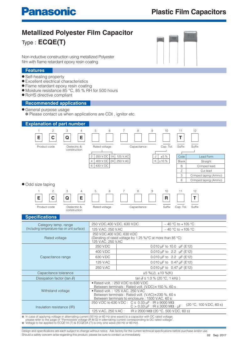
Design and specifications are each subject to change without notice. Ask factory for the current technical specifications before purchase and/or use.
Should a safety concern arise regarding this product, please be sure to contact us immediately.
Plastic Film Capacitors
1 2 3 4 5 6 7 8 9 11 12
E C Q E
Product code Dielectric &construction
SuffixRated voltage Capacitance SuffixCap. Tol.
10
T
Code
Blank
B
Z
3
6
Lead Form
Straight
Crimped lead
Cut lead
Crimped taping (Ammo)
Crimped taping (Ammo)
2 250 V.DC
4 400 V.DC
6 630 V.DC
1A 125 V.AC
2A 250 V.AC
J ±5 %
K ±10 %
1 2 3 4 5 6 7 8 9 11 12
E C Q E T
Product code Dielectric &construction
Cap. Tol.Rated voltage Capacitance SuffixSuffix
10
R
Explanation of part number
● Self-healing property● Excellent electrical characteristics● Flame retardant epoxy resin coating● Moisture resistance 85 °C, 85 % RH for 500 hours● RoHS directive compliant
● General purpose usage ✽ Please contact us when applications are CDI , ignitor etc.
● Odd size taping
Non-inductive construction using metallized Polyester
fi lm with fl ame retardant epoxy resin coating
Features
Metallized Polyester Film CapacitorType : ECQE(T)
Category temp. range(Including temperature-rise on unit surface)
250 V.DC,400 V.DC, 630 V.DC – 40 °C to +105 °C
125 V.AC, 250 V.AC – 40 °C to +105 °C
Rated voltage 250 V.DC,400 V.DC, 630 V.DC(Derating of rated voltage by 1.25 %/°C at more than 85 °C)125 V.AC, 250 V.AC
Capacitance range
250 V.DC 0.010 μF to 10.0 μF (E12)
400 V.DC 0.010 μF to 2.2 μF (E12)
630 V.DC 0.010 μF to 2.2 μF (E12)
125 V.AC 0.010 μF to 0.47 μF (E12)
250 V.AC 0.010 μF to 0.47 μF (E12)
Capacitance tolerance ±5 %(J), ±10 %(K)
Dissipation factor (tan d) tan d < 1.0 % (20 °C, 1 kHz )
Withstand voltage
• Rated volt. : 250 V.DC to 630 V.DC Between terminals : Rated volt. (V.DC)×150 %, 60 s• Rated volt. : 125 V.AC, 250 V.AC Between terminals : Rated volt. (V.AC)×230 %, 60 s Between terminals to enclosure : 1500 V.AC, 60 s
Insulation resistance (IR)
250 V.DC to 630 V.DC : C < 0.33 μF : IR > 9000 MΩ (20 °C, 100 V.DC, 60 s) C > 0.33 μF : IR > 3000 MΩ ∙ μF
125 V.AC, 250 V.AC : IR > 2000 MΩ (20 °C, 500 V.DC, 60 s)
✽ In case of applying voltage in alternating current (50 Hz or 60 Hz sine wave) to a capacitor with DC rated voltage, please refer to the page of “Permissible voltage (R.M.S) in alternating current corresponding to DC rated voltage”.✽ Voltage to be applied to ECQE1A (T) & ECQE2A (T) is only sine wave (50 Hz or 60 Hz).
Recommended applications
Specifi cations
Sep. 201702
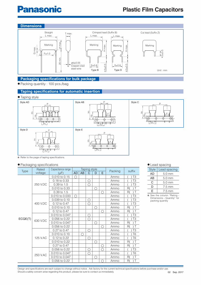
Design and specifications are each subject to change without notice. Ask factory for the current technical specifications before purchase and/or use.
Should a safety concern arise regarding this product, please be sure to contact us immediately.
Plastic Film Capacitors
L max.
Marking
G m
ax.
H m
ax.
20
min
.
L max.
H m
ax.
F±1.0
S±0.8
4.5
±0
.5
Marking
T max.
fd±0.05
Copper-clad
steel-wire
Straight Crimped lead (Suffix B)
Type B
L max.
S±0.8
Marking
H m
ax.
Type D 4.5
±0
.5
Cut lead (Suffix Z)
Marking
4.5
±0
.5
P
FH1
H0
P0
P
F
H1
H0
P0
F
P
P0
H1
H0
P
F
H1
H0
P0
F
P
P0
H1
H0
TypeRated
voltageCapacitance range
(μF)
Taping stylePacking suffi x
AD AB C D E
ECQE(T)
250 V.DC
0.010 to 0.15 ◯ Ammo ( ) T3
0.18 to 0.33 ◯ Ammo ( ) T3
0.39 to 1.5 ◯ Ammo ( ) T3
0.010 to 0.33 ◯ Ammo R( ) T
0.39 to 1.5 ◯ Ammo R( ) T
400 V.DC
0.010 to 0.033 ◯ Ammo ( ) T3
0.039 to 0.10 ◯ Ammo ( ) T3
0.12 to 0.47 ◯ Ammo ( ) T3
0.010 to 0.10 ◯ Ammo R( ) T
0.12 to 0.47 ◯ Ammo R( ) T
630 V.DC
0.010 to 0.047 ◯ Ammo ( ) T3
0.056 to 0.22 ◯ Ammo ( ) T3
0.010 to 0.047 ◯ Ammo R( ) T
0.056 to 0.22 ◯ Ammo R( ) T
125 V.AC
0.27 to 0.47 ◯ Ammo ( ) T3
0.010 to 0.10 ◯ Ammo ( ) T6
0.12 to 0.22 ◯ Ammo ( ) T6
0.010 to 0.22 ◯ Ammo R( ) T
0.27 to 0.47 ◯ Ammo R( ) T
250 V.AC
0.056 to 0.22 ◯ ◯ Ammo ( ) T3
0.010 to 0.047 ◯ Ammo ( ) T6
0.010 to 0.047 ◯ Ammo R( ) T
0.056 to 0.22 ◯ Ammo R( ) T
✽ Refer to the page of taping specifications.
✽ See the column “Rating · Dimensions · Quantity” for packing quantity
Unit : mm
● Packing quantity : 100 pcs./bag
● Taping style
● Packaging specifi cations ● Lead spacing
Style AD Style AB Style C
Style D Style E
Style Lead spacing
AD 5.0 mm
AB 5.0 mm
C 5.0 mm
D 7.5 mm
E 7.5 mm
Packaging specifi cations for bulk package
Taping specifi cations for automatic insertion
Dimensions
Sep. 201702

Design and specifications are each subject to change without notice. Ask factory for the current technical specifications before purchase and/or use.
Should a safety concern arise regarding this product, please be sure to contact us immediately.
Plastic Film Capacitors
Part No.Cap.(μF)
Dimensions (mm) Min. order Q'ty
L max.
T max.
H max. F S G max.fd
Taping Bulk
StraightCrimped
leadStraight
Crimped lead
StraightStandard5 mm
Odd size5 mm
Odd size7.5 mm
StraightCrimped
lead
ECQE2103◻T( ) 0.010 10.8 4.3 7.4 12.4 7.5 7.5 1.0 0.6
1500
–
1800
500500
ECQE2123◻T( ) 0.012 10.8 4.4 7.5 12.5 7.5 7.5 1.0 0.6
1700
ECQE2153◻T( ) 0.015 10.8 4.4 7.5 12.5 7.5 7.5 1.0 0.6
ECQE2183◻T( ) 0.018 10.8 4.4 7.5 12.5 7.5 7.5 1.0 0.6
ECQE2223◻T( ) 0.022 10.8 4.4 7.5 12.5 7.5 7.5 1.0 0.6
ECQE2273◻T( ) 0.027 10.8 4.4 7.5 12.5 7.5 7.5 1.0 0.6
ECQE2333◻T( ) 0.033 10.8 4.5 7.5 12.5 7.5 7.5 1.0 0.6
ECQE2393◻T( ) 0.039 10.8 4.5 7.5 12.5 7.5 7.5 1.0 0.6
ECQE2473◻T( ) 0.047 10.8 4.5 7.5 12.5 7.5 7.5 1.0 0.6
ECQE2563◻T( ) 0.056 10.8 4.8 7.9 12.9 7.5 7.5 1.0 0.6 1600
ECQE2683◻T( ) 0.068 10.8 4.5 7.5 12.5 7.5 7.5 1.0 0.6 1700
ECQE2823◻T( ) 0.082 10.8 4.9 8.0 13.0 7.5 7.5 1.0 0.6 1500
ECQE2104◻T( ) 0.10 10.8 5.8 8.4 13.4 7.5 7.5 1.0 0.6
1000
1300
ECQE2124◻T( ) 0.12 10.8 6.0 9.0 14.0 7.5 7.5 1.0 0.61200
ECQE2154◻T( ) 0.15 10.8 6.0 10.8 15.8 7.5 7.5 1.0 0.6
ECQE2184◻T( ) 0.18 12.5 5.0 10.3 15.3 10.0 10.0 1.0 0.6
–
8001400
ECQE2224◻T( ) 0.22 12.5 5.5 10.5 15.5 10.0 10.0 1.0 0.6 1300
ECQE2274◻T( ) 0.27 12.5 6.0 11.5 16.5 10.0 10.0 1.0 0.6 700 1200
ECQE2334◻T( ) 0.33 12.5 6.5 12.0 17.0 10.0 10.0 1.0 0.6 600 1100
ECQE2394◻T( ) 0.39 19.0 4.9 12.0 17.0 15.0 10.0 1.0 0.6 800 700
ECQE2474◻T( ) 0.47 19.0 5.3 12.5 17.5 15.0 10.0 1.0 0.6 700
600ECQE2564◻T( ) 0.56 19.0 5.5 13.0 18.0 15.0 10.0 1.0 0.6 800
ECQE2684◻T( ) 0.68 19.0 6.0 13.5 18.5 15.0 10.0 1.0 0.8 700
ECQE2824◻T( ) 0.82 19.0 6.5 14.5 19.5 15.0 10.0 1.0 0.8 600 500
ECQE2105◻T( ) 1.0 19.0 7.4 15.0 20.0 15.0 10.0 1.0 0.8500
400ECQE2125◻T( ) 1.2 19.0 8.0 15.9 20.9 15.0 10.0 1.0 0.8
ECQE2155◻T( ) 1.5 19.0 9.0 16.8 21.8 15.0 10.0 1.0 0.8 400
ECQE2185◻T( ) 1.8 26.5 7.5 15.5 20.5 22.5 15.0 1.0 0.8
– –
ECQE2225◻T( ) 2.2 26.5 8.5 16.3 21.3 22.5 15.0 1.0 0.8
ECQE2275◻T( ) 2.7 26.5 9.4 17.0 22.0 22.5 15.0 1.0 0.8
ECQE2335◻T( ) 3.3 26.5 10.3 18.0 23.0 22.5 15.0 1.5 0.8
ECQE2395◻T( ) 3.9 26.5 11.0 20.5 25.5 22.5 15.0 1.5 0.8
ECQE2475◻T( ) 4.7 26.5 12.0 21.5 26.5 22.5 15.0 1.5 0.8
ECQE2565◻T( ) 5.6 31.5 11.8 21.0 26.0 27.5 22.5 1.5 0.8
ECQE2685◻T( ) 6.8 31.5 13.0 22.4 27.4 27.5 22.5 1.5 0.8
ECQE2825◻T( ) 8.2 31.5 14.3 23.5 28.5 27.5 22.5 1.5 0.8 400
ECQE2106◻T( ) 10.0 31.5 15.9 25.8 30.8 27.5 22.5 1.5 0.8 300 400
● Rated voltage : 250 V.DC, Capacitance tolerance : ± 5 %(J), ±10 %(K)
✽ ◻ : Capacitance tolerance code ( ) : Suffi x for lead crimped or taped type
Type D : 0.010 μF to 0.33 μFType B : 0.39 μF to 10.0 μF
Rating · Dimensions · Quantity
Sep. 201702

Design and specifications are each subject to change without notice. Ask factory for the current technical specifications before purchase and/or use.
Should a safety concern arise regarding this product, please be sure to contact us immediately.
Plastic Film Capacitors
Part No.Cap.(μF)
Dimensions (mm) Min. order Q'ty
L max. T max.H max. F S G max.
fdTaping Bulk
Straight Crimped lead Straight Crimped lead StraightStandard
5 mmOdd size
5 mmOdd size7.5 mm
Straight ·Crimped lead
ECQE4103◻T( ) 0.010 10.8 4.3 7.4 12.4 7.5 7.5 1.0 0.6
1500–
1800
500
ECQE4123◻T( ) 0.012 10.8 4.4 7.5 12.5 7.5 7.5 1.0 0.61700ECQE4153◻T( ) 0.015 10.8 4.4 7.5 12.5 7.5 7.5 1.0 0.6
ECQE4183◻T( ) 0.018 10.8 4.4 7.5 12.5 7.5 7.5 1.0 0.6ECQE4223◻T( ) 0.022 10.8 4.8 7.9 12.9 7.5 7.5 1.0 0.6 1600ECQE4273◻T( ) 0.027 10.8 5.5 8.0 13.0 7.5 7.5 1.0 0.6 1400ECQE4333◻T( ) 0.033 10.8 6.0 9.0 14.0 7.5 7.5 1.0 0.6 1000 1200ECQE4393◻T( ) 0.039 12.5 4.9 8.0 13.0 10.0 10.0 1.0 0.6
–
900 1500ECQE4473◻T( ) 0.047 12.5 5.0 8.3 13.3 10.0 10.0 1.0 0.6ECQE4563◻T( ) 0.056 12.5 5.0 10.0 15.0 10.0 10.0 1.0 0.6ECQE4683◻T( ) 0.068 12.5 5.4 10.5 15.5 10.0 10.0 1.0 0.6
8001400
ECQE4823◻T( ) 0.082 12.5 5.8 11.0 16.0 10.0 10.0 1.0 0.6 1300ECQE4104◻T( ) 0.10 12.5 6.3 12.0 17.0 10.0 10.0 1.0 0.6 700 1200ECQE4124◻T( ) 0.12 19.0 5.0 10.0 15.0 15.0 10.0 1.0 0.6
800700ECQE4154◻T( ) 0.15 19.0 5.0 12.4 17.4 15.0 10.0 1.0 0.6
ECQE4184◻T( ) 0.18 19.0 5.4 12.5 17.5 15.0 10.0 1.0 0.6600ECQE4224◻T( ) 0.22 19.0 5.9 13.0 18.0 15.0 10.0 1.0 0.6 700
ECQE4274◻T( ) 0.27 19.0 6.5 14.3 19.3 15.0 10.0 1.0 0.8600 500ECQE4334◻T( ) 0.33 19.0 7.0 14.9 19.9 15.0 10.0 1.0 0.8
ECQE4394◻T( ) 0.39 19.0 7.5 15.4 20.4 15.0 10.0 1.0 0.8500 400ECQE4474◻T( ) 0.47 19.0 7.8 17.0 22.0 15.0 10.0 1.0 0.8
ECQE4564◻T( ) 0.56 26.5 6.5 16.0 21.0 22.5 15.0 1.0 0.8
– –
ECQE4684◻T( ) 0.68 26.5 7.0 16.5 21.5 22.5 15.0 1.0 0.8ECQE4824◻T( ) 0.82 26.5 7.9 17.3 22.3 22.5 15.0 1.0 0.8ECQE4105◻T( ) 1.0 26.5 8.5 18.0 23.0 22.5 15.0 1.0 0.8ECQE4125◻T( ) 1.2 26.5 9.5 18.9 23.9 22.5 15.0 1.0 0.8ECQE4155◻T( ) 1.5 31.5 9.5 19.0 24.0 27.5 22.5 1.0 0.8ECQE4185◻T( ) 1.8 31.5 11.0 20.5 25.5 27.5 22.5 1.5 0.8ECQE4225◻T( ) 2.2 31.5 11.0 22.0 27.0 27.5 22.5 1.5 0.8
Part No.Cap.(μF)
Dimensions (mm) Min. order Q'ty
L max. T max.H max. F S G max.
fdTaping Bulk
Straight Crimped lead Straight Crimped lead StraightOdd size
5 mmOdd size7.5 mm
Straight Crimped lead
ECQE6103◻T( ) 0.010 12.5 4.5 7.5 12.5 10.0 10.0 1.0 0.6900 1600
500500
ECQE6123◻T( ) 0.012 12.5 4.5 7.8 12.8 10.0 10.0 1.0 0.6ECQE6153◻T( ) 0.015 12.5 5.0 8.2 13.2 10.0 10.0 1.0 0.6
8001400ECQE6183◻T( ) 0.018 12.5 4.9 10.0 15.0 10.0 10.0 1.0 0.6
ECQE6223◻T( ) 0.022 12.5 5.3 10.5 15.5 10.0 10.0 1.0 0.61300ECQE6273◻T( ) 0.027 12.5 5.5 10.9 15.9 10.0 10.0 1.0 0.6
ECQE6333◻T( ) 0.033 12.5 6.0 11.9 16.9 10.0 10.0 1.0 0.6700 1200ECQE6393◻T( ) 0.039 12.5 6.0 13.4 18.4 10.0 10.0 1.0 0.6
ECQE6473◻T( ) 0.047 12.5 6.5 13.5 18.5 10.0 10.0 1.0 0.6 600 1100ECQE6563◻T( ) 0.056 19.0 5.4 10.5 15.5 15.0 10.0 1.0 0.6 800
600ECQE6683◻T( ) 0.068 19.0 5.8 11.0 16.0 15.0 10.0 1.0 0.6 700ECQE6823◻T( ) 0.082 19.0 6.5 12.0 17.0 15.0 10.0 1.0 0.6
600 500ECQE6104◻T( ) 0.10 19.0 6.3 14.0 19.0 15.0 10.0 1.0 0.6ECQE6124◻T( ) 0.12 19.0 6.3 14.5 19.5 15.0 10.0 1.0 0.8ECQE6154◻T( ) 0.15 19.0 7.5 15.4 20.4 15.0 10.0 1.0 0.8
500 400ECQE6184◻T( ) 0.18 19.0 8.0 16.0 21.0 15.0 10.0 1.0 0.8
ECQE6224◻T( ) 0.22 19.0 9.0 16.5 21.5 15.0 10.0 1.0 0.8 400ECQE6274◻T( ) 0.27 26.5 7.0 16.5 21.5 22.5 15.0 1.0 0.8
– –
ECQE6334◻T( ) 0.33 26.5 7.8 17.0 22.0 22.5 15.0 1.0 0.8ECQE6394◻T( ) 0.39 26.5 8.5 17.9 22.9 22.5 15.0 1.0 0.8ECQE6474◻T( ) 0.47 26.5 9.3 18.5 23.5 22.5 15.0 1.0 0.8ECQE6564◻T( ) 0.56 26.5 10.0 20.0 25.0 22.5 15.0 1.5 0.8ECQE6684◻T( ) 0.68 26.5 11.5 21.0 26.0 22.5 15.0 1.5 0.8ECQE6824◻T( ) 0.82 31.5 11.3 20.5 25.5 27.5 22.5 1.5 0.8ECQE6105◻T( ) 1.0 31.5 12.5 21.9 26.9 27.5 22.5 1.5 0.8ECQE6125◻T( ) 1.2 31.5 13.5 23.0 28.0 27.5 22.5 1.5 0.8ECQE6155◻T( ) 1.5 31.5 15.3 24.7 29.7 27.5 22.5 1.5 0.8 400ECQE6185◻T( ) 1.8 31.5 16.8 27.0 32.0 27.5 22.5 1.5 0.8
300 400ECQE6225◻T( ) 2.2 31.5 19.5 29.0 34.0 27.5 22.5 1.5 0.8
● Rated voltage : 400 V.DC, Capacitance tolerance : ± 5 %(J), ±10 %(K)
● Rated voltage : 630 V.DC, Capacitance tolerance : ± 5 %(J), ±10 %(K)
✽ ◻ : Capacitance tolerance code ( ) : Suffi x for lead crimped or taped type
✽ ◻ : Capacitance tolerance code ( ) : Suffi x for lead crimped or taped type
Type D : 0.010 μF to 0.10 μFType B : 0.12 μF to 2.2 μF
Type D : 0.010 μF to 0.047 μFType B : 0.056 μF to 2.2 μF
Rating · Dimensions · Quantity
Sep. 201702

Design and specifications are each subject to change without notice. Ask factory for the current technical specifications before purchase and/or use.
Should a safety concern arise regarding this product, please be sure to contact us immediately.
Plastic Film Capacitors
Part No.Cap.(μF)
Dimensions (mm) Min. order Q'ty
L max. T max.H max. F S G max.
fdTaping Bulk
Straight Crimped lead Straight Crimped lead StraightStandard
5 mmOdd size
5 mmOdd size7.5 mm
Straight ·Crimped lead
ECQE1A103◻T( ) 0.010 11.0 4.5 7.5 12.5 7.5 7.5 1.0 0.6
1500
–
1700
500
ECQE1A123◻T( ) 0.012 11.0 4.4 7.5 12.5 7.5 7.5 1.0 0.6ECQE1A153◻T( ) 0.015 11.0 4.4 7.5 12.5 7.5 7.5 1.0 0.6ECQE1A183◻T( ) 0.018 11.0 4.4 7.5 12.5 7.5 7.5 1.0 0.6ECQE1A223◻T( ) 0.022 11.0 4.4 7.5 12.5 7.5 7.5 1.0 0.6ECQE1A273◻T( ) 0.027 11.0 4.4 7.5 12.5 7.5 7.5 1.0 0.6ECQE1A333◻T( ) 0.033 11.0 4.5 7.8 12.8 7.5 7.5 1.0 0.6ECQE1A393◻T( ) 0.039 11.0 4.5 7.8 12.8 7.5 7.5 1.0 0.6ECQE1A473◻T( ) 0.047 11.0 5.5 8.0 13.0 7.5 7.5 1.0 0.6 1400ECQE1A563◻T( ) 0.056 11.0 5.9 8.5 13.5 7.5 7.5 1.0 0.6
1000
1300ECQE1A683◻T( ) 0.068 11.0 6.3 9.4 14.4 7.5 7.5 1.0 0.6 1200ECQE1A823◻T( ) 0.082 11.0 6.5 9.8 14.8 7.5 7.5 1.0 0.6
1100ECQE1A104◻T( ) 0.10 11.0 6.5 11.8 16.8 7.5 7.5 1.0 0.6ECQE1A124◻T( ) 0.12 13.0 5.9 11.5 16.5 10.0 10.0 1.0 0.6
–
600ECQE1A154◻T( ) 0.15 13.0 6.5 12.0 17.0 10.0 10.0 1.0 0.6 1000ECQE1A184◻T( ) 0.18 13.0 7.0 12.5 17.5 10.0 10.0 1.0 0.6
500 900
ECQE1A224◻T( ) 0.22 13.0 7.5 13.4 18.4 10.0 10.0 1.0 0.6 800ECQE1A274◻T( ) 0.27 19.0 6.3 12.0 17.0 15.0 10.0 1.0 0.6 600 500ECQE1A334◻T( ) 0.33 19.0 6.9 12.5 17.5 15.0 10.0 1.0 0.6
500 400ECQE1A394◻T( ) 0.39 19.0 7.4 13.0 18.0 15.0 10.0 1.0 0.6ECQE1A474◻T( ) 0.47 19.0 7.5 15.3 20.3 15.0 10.0 1.0 0.6
Part No.Cap.(μF)
Dimensions (mm) Min. order Q'ty
L max. T max.H max. F S G max.
fdTaping Bulk
Straight Crimped lead Straight Crimped lead StraightOdd size
5 mmOdd size7.5 mm
Straight ·Crimped lead
ECQE2A103◻T( ) 0.010 13.0 5.5 10.8 15.8 10.0 10.0 1.0 0.6 800 1300
500
ECQE2A123◻T( ) 0.012 13.0 6.0 11.5 16.5 10.0 10.0 1.0 0.6 700 1200ECQE2A153◻T( ) 0.015 13.0 6.3 9.9 14.9 10.0 10.0 1.0 0.6 600 1100ECQE2A183◻T( ) 0.018 13.0 6.0 11.9 16.9 10.0 10.0 1.0 0.6
700 1200ECQE2A223◻T( ) 0.022 13.0 6.0 11.5 16.5 10.0 10.0 1.0 0.6ECQE2A273◻T( ) 0.027 13.0 5.5 10.9 15.9 10.0 10.0 1.0 0.6 800 1300ECQE2A333◻T( ) 0.033 13.0 6.0 11.9 16.9 10.0 10.0 1.0 0.6
700 1200ECQE2A393◻T( ) 0.039 13.0 6.0 13.4 18.4 10.0 10.0 1.0 0.6ECQE2A473◻T( ) 0.047 13.0 6.5 14.4 19.4 10.0 10.0 1.0 0.6 600 1100ECQE2A563◻T( ) 0.056 19.0 5.4 10.5 15.5 15.0 10.0 1.0 0.6 800
600ECQE2A683◻T( ) 0.068 19.0 5.8 11.0 16.0 15.0 10.0 1.0 0.6 700ECQE2A823◻T( ) 0.082 19.0 6.3 12.0 17.0 15.0 10.0 1.0 0.6
600 500ECQE2A104◻T( ) 0.10 19.0 6.3 14.0 19.0 15.0 10.0 1.0 0.6ECQE2A124◻T( ) 0.12 19.0 6.8 14.5 19.5 15.0 10.0 1.0 0.8ECQE2A154◻T( ) 0.15 19.0 7.5 15.4 20.4 15.0 10.0 1.0 0.8
500 400ECQE2A184◻T( ) 0.18 19.0 8.0 16.0 21.0 15.0 10.0 1.0 0.8
ECQE2A224◻T( ) 0.22 19.0 9.0 16.9 21.9 15.0 10.0 1.0 0.8 400ECQE2A274◻T( ) 0.27 26.5 7.0 16.5 21.5 22.5 15.0 1.0 0.8
– –ECQE2A334◻T( ) 0.33 26.5 7.8 17.0 22.0 22.5 15.0 1.0 0.8ECQE2A394◻T( ) 0.39 26.5 8.5 17.9 22.9 22.5 15.0 1.0 0.8ECQE2A474◻T( ) 0.47 26.5 9.3 18.5 23.5 22.5 15.0 1.0 0.8
● Rated voltage : 125 V.AC, Capacitance tolerance : ± 5 %(J), ±10 %(K) Noise suppression Capacitors (Across-the-line)
● Rated voltage : 250 V.AC, Capacitance tolerance : ± 5 %(J), ±10 %(K) Noise suppression Capacitors (Across-the-line)
✽ ◻ : Capacitance tolerance code ( ) : Suffi x for lead crimped or taped type
✽ ◻ : Capacitance tolerance code ( ) : Suffi x for lead crimped or taped type
Type D : 0.010 μF to 0.22 μFType B : 0.27 μF to 0.47 μF
Type D : 0.010 μF to 0.047 μFType B : 0.056 μF to 0.47 μF
Notice for AC rated
AC rated capacitors complying with clause 1 of ''Electrical Appliance and Material Safety Law''.
As for clause 2 of ''Electrical Appliance and Material Safety Law'', please use ECQUA type or ECQUL type.
When using these capacitors as a across-the-line capacitor, it shall be required to follow either item 1. or item 2. condition.
1. Capacitor shall be connected in parallel with varistor (Specifi ed varistor voltage in table 1.)
2. Voltage applied for capacitor shall not exceed other than specifi ed in table 1, when using these capacitors.
Capacitor rated voltage Varistor voltage Pulse voltage125 V.AC 250 V 250 V0-P
250 V.AC 470 V 630 V0-P
Table 1
Rating · Dimensions · Quantity
Sep. 201702

Design and specifications are each subject to change without notice. Ask factory for the current technical specifications before purchase and/or use.
Should a safety concern arise regarding this product, please be sure to contact us immediately.
Plastic Film Capacitors
1 2 3 4 5 6 7 8 9 11
E C W F
Product code Dielectric &construction
SuffixRated voltage Capacitance SuffixCap. Tol.
10
L
Code
Blank
B
C
Lead Form
Straight
Crimped lead
Cut lead
4 400 V.DC
6 630 V.DC
H ±3 %
J ±5 %
1 2 3 4 5 6 7 8 9 11
E C W F L
Product code Dielectric &construction
Cap. Tol.Capacitance SuffixSuffix
10
R
Rated voltage
● Small size● Excellent frequency characteristics● Low loss● Flame retardant epoxy resin coating● 85 °C, 85 % RH, W.V. × 1.0 for 500 hours● RoHS directive compliant
● Lighting● High frequency and high current circuit
● Odd size taping
Non-inductive construction using metallized polypropylene
fi lm with fl ame retardant epoxy resin coating.
Metallized Polypropylene Film CapacitorType : ECWF(L)
Specifi cationsCategory temp. range
(Including temperature-rise on unit surface)– 40 °C to +105 °C
Rated voltage 400 V.DC, 630 V.DC
Capacitance range400 V.DC 0.022 μF to 2.4 μF
630 V.DC 0.010 μF to 1.3 μF
Capacitance tolerance ±3 %(H), ±5 %(J)
Dissipation factor (tan d)tan d < 0.05 % ( 20 °C, 1 kHz )
tan d < 0.20 % ( 20 °C, 10 kHz )
Withstand voltage Between terminals : Rated volt. (V.DC)×150 %, 60 s
Insulation resistance (IR)C < 0.33 μF : IR > 9000 MΩ (20 °C, 100 V.DC, 60 s for 400 V.DC)
C > 0.33 μF : IR > 3000 MΩ ∙ μF (20 °C, 500 V.DC, 60 s for 630 V.DC)
✽ In case of applying voltage in alternating current (50 Hz or 60 Hz sine wave) to a capacitor with DC rated voltage, please refer to the page of “Permissible voltage (R.M.S) in alternating current corresponding to DC rated voltage”.
Features
Recommended applications
Explanation of part number
Sep. 201703

Design and specifications are each subject to change without notice. Ask factory for the current technical specifications before purchase and/or use.
Should a safety concern arise regarding this product, please be sure to contact us immediately.
Plastic Film Capacitors
L max.
Marking
1.5
ma
x.
H m
ax.
25
min
.F±1.5
Straight
L max.
H m
ax.
S±0.8
4.5
±0.5
Marking
T max.
0d±0.05
Copper-wire or
Copper-clad
steel-wire
Crimped lead
(Suffix B)
4.5±
0.5
Marking
Cut lead
(Suffix Z)
Style D
F
P
P0
H0
H1
F
Style E
P
P0
H1
H0
TypeRated voltage
(V.DC)Capacitance range
(μF)
Taping stylePacking suffi x
AD AB C D E
ECWF(L)400
0.022 to 0.091 ◯ Ammo R( ) L
0.10 to 1.0 ◯ Ammo R( ) L
6300.010 to 0.043 ◯ Ammo R( ) L
0.047 to 0.43 ◯ Ammo R( ) L
✽ Refer to the page of taping specifications.
Unit : mm
● Packing quantity : 100 pcs./bag
● Packaging specifi cations ● Lead spacing
Style Lead spacing
D 7.5 mm
E 7.5 mm
● Taping style
Dimensions
Packaging specifi cations for bulk package
Taping specifi cations for automatic insertion
Sep. 201703

Design and specifications are each subject to change without notice. Ask factory for the current technical specifications before purchase and/or use.
Should a safety concern arise regarding this product, please be sure to contact us immediately.
Plastic Film Capacitors
Part No.Cap.(μF)
Dimensions (mm) Min. order Q'ty
L max. T max.H max. F S
fdTaping Bulk
StraightCrimped
leadStraight
Crimped lead
7.5 mm StraightCrimped
lead
ECWF4223◻L( ) 0.022 12.5 5.8 8.6 13.6 10.0 7.5 0.61100
500
500
ECWF4243◻L( ) 0.024 12.5 6.0 8.8 13.8 10.0 7.5 0.6
ECWF4273◻L( ) 0.027 12.5 6.2 9.0 14.0 10.0 7.5 0.61000
ECWF4303◻L( ) 0.030 12.5 6.4 9.3 14.3 10.0 7.5 0.6
ECWF4333◻L( ) 0.033 12.5 6.7 9.5 14.5 10.0 7.5 0.6 900
ECWF4363◻L( ) 0.036 12.5 5.7 8.4 13.4 10.0 7.5 0.6
1100ECWF4393◻L( ) 0.039 12.5 5.8 8.6 13.6 10.0 7.5 0.6
ECWF4433◻L( ) 0.043 12.5 6.0 8.8 13.8 10.0 7.5 0.6
ECWF4473◻L( ) 0.047 12.5 6.2 9.0 14.0 10.0 7.5 0.6
1000ECWF4513◻L( ) 0.051 12.5 6.4 9.2 14.2 10.0 7.5 0.6
ECWF4563◻L( ) 0.056 12.5 6.6 9.4 14.4 10.0 7.5 0.6
ECWF4623◻L( ) 0.062 13.0 6.8 9.6 14.6 10.0 7.5 0.8
900ECWF4683◻L( ) 0.068 13.0 7.0 9.9 14.9 10.0 7.5 0.8
ECWF4753◻L( ) 0.075 13.0 7.3 10.1 15.1 10.0 7.5 0.8
ECWF4823◻L( ) 0.082 13.0 7.5 10.4 15.4 10.0 7.5 0.8 800
ECWF4913◻L( ) 0.091 13.0 7.8 10.7 15.7 10.0 7.5 0.8
ECWF4104◻L( ) 0.10 15.5 6.5 11.0 16.0 12.5 7.5 0.8 500
ECWF4114◻L( ) 0.11 15.5 6.8 11.3 16.3 12.5 7.5 0.8
400
ECWF4124◻L( ) 0.12 15.5 7.0 11.5 16.5 12.5 7.5 0.8
ECWF4134◻L( ) 0.13 15.5 7.2 11.8 16.8 12.5 7.5 0.8
ECWF4154◻L( ) 0.15 15.5 7.6 12.2 17.2 12.5 7.5 0.8
ECWF4164◻L( ) 0.16 15.5 7.8 12.4 17.4 12.5 7.5 0.8
ECWF4184◻L( ) 0.18 15.5 8.2 12.8 17.8 12.5 7.5 0.8
ECWF4204◻L( ) 0.20 15.5 8.6 13.3 18.3 12.5 7.5 0.8
300
ECWF4224◻L( ) 0.22 15.5 9.0 13.6 18.6 12.5 7.5 0.8
ECWF4244◻L( ) 0.24 18.0 8.3 13.0 18.0 15.0 10.0 0.8
ECWF4274◻L( ) 0.27 18.0 8.8 13.4 18.4 15.0 10.0 0.8
ECWF4304◻L( ) 0.30 18.0 9.2 13.9 18.9 15.0 10.0 0.8
ECWF4334◻L( ) 0.33 18.0 9.6 14.3 19.3 15.0 10.0 0.8
ECWF4364◻L( ) 0.36 18.0 9.9 14.7 19.7 15.0 10.0 0.8
ECWF4394◻L( ) 0.39 18.0 10.3 15.1 20.1 15.0 10.0 0.8
ECWF4434◻L( ) 0.43 18.0 10.7 15.6 20.6 15.0 10.0 0.8
ECWF4474◻L( ) 0.47 18.0 11.2 16.1 21.1 15.0 10.0 0.8 200
ECWF4514◻L( ) 0.51 20.5 10.3 16.8 21.8 17.5 12.5 0.8 300
ECWF4564◻L( ) 0.56 20.5 10.7 17.3 22.3 17.5 12.5 0.8
ECWF4624◻L( ) 0.62 20.5 11.3 17.9 22.9 17.5 12.5 0.8
200
ECWF4684◻L( ) 0.68 20.5 11.8 18.5 23.5 17.5 12.5 0.8
ECWF4754◻L( ) 0.75 20.5 12.3 19.1 24.1 17.5 12.5 0.8
ECWF4824◻L( ) 0.82 23.0 11.8 18.5 23.5 20.0 12.5 0.8
ECWF4914◻L( ) 0.91 23.0 12.4 19.2 24.2 20.0 12.5 0.8
ECWF4105◻L( ) 1.0 23.0 13.0 19.8 24.8 20.0 12.5 0.8
ECWF4115◻L( ) 1.1 23.0 13.6 20.5 25.5 20.0 12.5 0.8
–
ECWF4125◻L( ) 1.2 28.0 12.3 19.1 24.1 25.0 17.5 0.8
ECWF4135◻L( ) 1.3 28.0 12.8 19.6 24.6 25.0 17.5 0.8
ECWF4155◻L( ) 1.5 28.0 13.7 20.7 25.7 25.0 17.5 0.8
ECWF4165◻L( ) 1.6 28.0 14.2 21.2 26.2 25.0 17.5 0.8
ECWF4185◻L( ) 1.8 28.0 15.2 22.2 27.2 25.0 17.5 0.8
ECWF4205◻L( ) 2.0 28.0 16.0 23.1 28.1 25.0 17.5 0.8
400ECWF4225◻L( ) 2.2 28.0 16.8 24.0 29.0 25.0 17.5 0.8
ECWF4245◻L( ) 2.4 28.0 17.5 24.8 29.8 25.0 17.5 0.8
● Rated voltage : 400 V.DC, Capacitance tolerance : ± 3 %(J), ±5 %(J)
✽ ◻ : Capacitance tolerance code ( ) : Suffi x for lead crimped
Rating · Dimensions · Quantity
Sep. 201703

Design and specifications are each subject to change without notice. Ask factory for the current technical specifications before purchase and/or use.
Should a safety concern arise regarding this product, please be sure to contact us immediately.
Plastic Film Capacitors
Part No.Cap.(μF)
Dimensions (mm) Min. order Q'ty
L max. T max.H max. F S
fdTaping Bulk
StraightCrimped
leadStraight
Crimped lead
7.5 mm StraightCrimped
lead
ECWF6103◻L( ) 0.010 12.5 5.2 8.0 13.0 10.0 7.5 0.6
1200
500 500
ECWF6113◻L( ) 0.011 12.5 5.4 8.2 13.2 10.0 7.5 0.6
ECWF6123◻L( ) 0.012 12.5 5.5 8.3 13.3 10.0 7.5 0.6
ECWF6133◻L( ) 0.013 12.5 5.6 8.5 13.5 10.0 7.5 0.6
1100ECWF6153◻L( ) 0.015 12.5 5.9 8.7 13.7 10.0 7.5 0.6
ECWF6163◻L( ) 0.016 12.5 6.0 8.9 13.9 10.0 7.5 0.6
ECWF6183◻L( ) 0.018 12.5 6.2 9.1 14.1 10.0 7.5 0.6
1000
ECWF6203◻L( ) 0.020 12.5 6.5 9.3 14.3 10.0 7.5 0.6
ECWF6223◻L( ) 0.022 12.5 6.2 9.0 14.0 10.0 7.5 0.6
ECWF6243◻L( ) 0.024 12.5 6.4 9.2 14.2 10.0 7.5 0.6
ECWF6273◻L( ) 0.027 13.0 6.6 9.5 14.5 10.0 7.5 0.8
ECWF6303◻L( ) 0.030 13.0 6.9 9.7 14.7 10.0 7.5 0.8
900ECWF6333◻L( ) 0.033 13.0 7.1 10.0 15.0 10.0 7.5 0.8
ECWF6363◻L( ) 0.036 13.0 7.3 10.2 15.2 10.0 7.5 0.8
ECWF6393◻L( ) 0.039 13.0 7.6 10.4 15.4 10.0 7.5 0.8 800
ECWF6433◻L( ) 0.043 13.0 7.9 10.7 15.7 10.0 7.5 0.8
ECWF6473◻L( ) 0.047 15.5 6.4 10.8 15.8 12.5 7.5 0.8 500
ECWF6513◻L( ) 0.051 15.5 6.6 11.0 16.0 12.5 7.5 0.8
ECWF6563◻L( ) 0.056 15.5 6.8 11.2 16.2 12.5 7.5 0.8
400
ECWF6623◻L( ) 0.062 15.5 7.1 11.5 16.5 12.5 7.5 0.8
ECWF6683◻L( ) 0.068 15.5 7.4 11.8 16.8 12.5 7.5 0.8
ECWF6753◻L( ) 0.075 15.5 7.7 12.1 17.1 12.5 7.5 0.8
ECWF6823◻L( ) 0.082 15.5 8.0 12.4 17.4 12.5 7.5 0.8
ECWF6913◻L( ) 0.091 15.5 8.3 12.7 17.7 12.5 7.5 0.8
ECWF6104◻L( ) 0.10 18.0 7.7 12.1 17.1 15.0 10.0 0.8
ECWF6114◻L( ) 0.11 18.0 8.0 12.4 17.4 15.0 10.0 0.8
ECWF6124◻L( ) 0.12 18.0 8.3 12.7 17.7 15.0 10.0 0.8
300
ECWF6134◻L( ) 0.13 18.0 8.5 13.0 18.0 15.0 10.0 0.8
ECWF6154◻L( ) 0.15 18.0 9.1 13.5 18.5 15.0 10.0 0.8
ECWF6164◻L( ) 0.16 18.0 9.3 13.8 18.8 15.0 10.0 0.8
ECWF6184◻L( ) 0.18 18.0 9.8 14.2 19.1 15.0 10.0 0.8
ECWF6204◻L( ) 0.20 18.0 10.3 14.7 19.7 15.0 10.0 0.8
ECWF6224◻L( ) 0.22 18.0 10.8 15.5 20.5 15.0 10.0 0.8
ECWF6244◻L( ) 0.24 18.0 11.2 15.9 20.9 15.0 10.0 0.8 200
ECWF6274◻L( ) 0.27 20.5 10.4 16.7 21.7 17.5 12.5 0.8 300
ECWF6304◻L( ) 0.30 20.5 10.9 17.2 22.2 17.5 12.5 0.8
ECWF6334◻L( ) 0.33 20.5 11.4 17.7 22.7 17.5 12.5 0.8
200ECWF6364◻L( ) 0.36 20.5 11.9 18.5 23.5 17.5 12.5 0.8
ECWF6394◻L( ) 0.39 20.5 12.4 19.0 24.0 17.5 12.5 0.8
ECWF6434◻L( ) 0.43 20.5 13.0 19.5 24.5 17.5 12.5 0.8
ECWF6474◻L( ) 0.47 20.5 13.5 20.1 25.1 17.5 12.5 0.8
–
ECWF6514◻L( ) 0.51 28.0 11.1 17.3 22.3 25.0 17.5 0.8
ECWF6564◻L( ) 0.56 28.0 11.6 17.8 22.8 25.0 17.5 0.8
ECWF6624◻L( ) 0.62 28.0 12.1 18.7 23.7 25.0 17.5 0.8
ECWF6684◻L( ) 0.68 28.0 12.7 19.3 24.3 25.0 17.5 0.8
ECWF6754◻L( ) 0.75 28.0 13.3 19.9 24.9 25.0 17.5 0.8
ECWF6824◻L( ) 0.82 28.0 13.9 20.5 25.5 25.0 17.5 0.8
ECWF6914◻L( ) 0.91 28.0 14.6 21.2 26.2 25.0 17.5 0.8
ECWF6105◻L( ) 1.0 28.0 15.5 22.3 27.3 25.0 17.5 0.8
ECWF6115◻L( ) 1.1 28.0 16.3 23.0 28.0 25.0 17.5 0.8
400 400ECWF6125◻L( ) 1.2 28.0 17.0 23.7 28.7 25.0 17.5 0.8
ECWF6135◻L( ) 1.3 28.0 17.6 24.4 29.4 25.0 17.5 0.8
● Rated voltage : 630 V.DC, Capacitance tolerance : ± 3 %(J), ±5 %(J)
✽ ◻ : Capacitance tolerance code ( ) : Suffi x for lead crimped
Rating · Dimensions · Quantity
Sep. 201703

Design and specifications are each subject to change without notice. Ask factory for the current technical specifications before purchase and/or use.
Should a safety concern arise regarding this product, please be sure to contact us immediately.
Plastic Film Capacitors
1 2 3 4 5 6 7 8 9 11
E C W F
12
Product code Dielectric &construction
SuffixRated voltage Capacitance SuffixCap. Tol.
10
A
Code
Blank
B
Q
C
Lead Form
Straight
Crimped lead
Crimped lead
Cut lead
2 250 V.DC
2W 450 V.DC
H ±3 %
J ±5 %
J ±5 %
K ±10 %
1 2 3 4 5 6 7 8 9 11
E C W F
12
Product code Dielectric &construction
Cap. Tol.Rated voltage Capacitance SuffixSuffix
10
R A
1 2 3 4 5 6 7 8 9 11
E C W F A 2 J
12
Product code Dielectric &construction
Cap. Tol.Rated voltage Capacitance Suffix
10
J
Code
Blank
B
Q
C
4
Lead Form
Straight
Crimped lead
Crimped lead
Cut lead
Odd size taping
2J 630 V.DC J ±5 %
● Small size● Excellent frequency characteristics● Low loss● Low Hum Sound Noise● Flame retardant epoxy resin coating● 85 degree C , 85 %RH , 500 V.DC , 500 hours (630 V.DC)● RoHS directive compliant
● 250 V.DC, 630 V.DC : High frequency and high current circuit● 450 V.DC : Active fi lter circuit
● 250 V.DC, 450 V.DC (Odd size taping)
● 630 V.DC (Bulk, Odd size taping)
● 250 V.DC, 450 V.DC (Bulk)
Non-inductive construction using metallized polypropylene fi lm
with fl ame retardant epoxy resin coating.
Features
Metallized Polypropylene Film CapacitorType : ECWF(A)
Recommended applications
Explanation of part number
Sep. 201702

Design and specifications are each subject to change without notice. Ask factory for the current technical specifications before purchase and/or use.
Should a safety concern arise regarding this product, please be sure to contact us immediately.
Plastic Film Capacitors
T max.
0d±0.05
Copper-wire or
Copper-clad
steel-wire
L max.
Marking
G m
ax.
H m
ax.
25 m
in.
F±1.0
Straight Crimped lead
(Suffix B)
L max.
H m
ax.
S±0.8
4.5±0
.5
Marking
Crimped lead
(Suffix Q)
Cut lead
(Suffix C)
L max.
S±0.8
Marking
H m
ax.
4.5±0
.5
4.5±
0.5
Marking
Type B Type D
● Packing quantity : 100 pcs./bag
Packaging specifi cations for bulk package
Category temp. range
(Including temperature-rise on unit surface)– 40 °C to +105 °C
Rated voltage
250 V.DC
450 V.DC (Derating of rated voltage by 1.25%/°C at more than 85 °C)
Peak to peak voltage applied on the capacitor should be less than
240 Vp-p, and zero to peak voltage should be less than 450 Vo-p.
630 V.DC (Derating of rated voltage by 1.0%/°C at more than 85 °C)
Capacitance range
250 V.DC 0.1 μF to 6.8 μF
450 V.DC 0.1 μF to 4.7 μF
630 V.DC 0.1 μF to 2.2 μF
Capacitance tolerance
250 V.DC ±3 %(H), ±5 %(J)
450 V.DC ±5 %(J), ±10 %(K)
630 V.DC ±5 %(J)
Dissipation factor (tan d) tan d < 0.1 % (20 °C, 1 kHz)
Withstand voltage Between terminals : Rated volt. (V.DC)×150 %, 60 s
Insulation resistance (IR)
250 V.DCC < 0.33 μF : IR > 9000 MΩ
(20 °C, 100 V.DC, 60 s)C > 0.33 μF : IR > 3000 MΩ ∙ μF
450 V.DCC < 0.33 μF : IR > 30000 MΩ
(20 °C, 100 V.DC, 60 s)C > 0.33 μF : IR > 10000 MΩ ∙ μF
630 V.DCC < 0.33 μF : IR > 9000 MΩ
(20 °C, 500 V.DC, 60 s)C > 0.33 μF : IR > 3000 MΩ ∙ μF
✽ In case of applying voltage in alternating current (50 Hz or 60 Hz sine wave) to a capacitor with DC rated voltage, please refer to the page of “Permissible voltage (R.M.S) in alternating current corresponding to DC rated voltage”.
Unit : mm
Specifi cations
Dimensions
Sep. 201702

Design and specifications are each subject to change without notice. Ask factory for the current technical specifications before purchase and/or use.
Should a safety concern arise regarding this product, please be sure to contact us immediately.
Plastic Film Capacitors
Style D
F
P
P0
H0
H1
F
Style E
P
P0
H1
H0
Style F
F
P
H1
H0
P0
Part No.Cap.(μF)
Dimensions (mm) Min. order Q'ty
L max. T max.H max. F S G max.
fdTaping Bulk
StraightCrimped lead(Suffix B)
Crimped lead(Suffix Q)
StraightCrimped lead(Suffix B)
Crimped lead(Suffix Q)
Straight 7.5 mmStraight ·
Crimped lead
ECWF2104◻A( ) 0.10 13.0 5.0
–
14.1 14.1
–
7.5 10.0
–
0.6 1300
500
ECWF2124◻A( ) 0.12 13.0 5.3 14.4 14.4 7.5 10.0 0.6 1200
ECWF2154◻A( ) 0.15 13.0 5.6 14.7 14.7 7.5 10.0 0.61100
ECWF2184◻A( ) 0.18 13.0 5.9 15.1 15.1 7.5 10.0 0.6
ECWF2224◻A( ) 0.22 13.0 6.3 15.4 15.4 7.5 10.0 0.6 1000
ECWF2274◻A( ) 0.27 13.0 6.8 15.9 15.9 7.5 10.0 0.6 900
ECWF2334◻A( ) 0.33 13.0 7.3 16.4 16.4 7.5 10.0 0.6
ECWF2394◻A( ) 0.39 13.0 7.8 16.9 16.9 7.5 10.0 0.6 800
ECWF2474◻A( ) 0.47 13.0 8.4 17.6 17.6 7.5 10.0 0.6 700
ECWF2564◻A( ) 0.56 18.1 6.9 16.4 18.4 7.5 15.0 0.8
400ECWF2684◻A( ) 0.68 18.1 7.4 17.0 19.0 7.5 15.0 0.8
ECWF2824◻A( ) 0.82 18.1 8.0 17.6 19.6 7.5 15.0 0.8
ECWF2105◻A( ) 1.0 18.1 8.5 13.3 18.3 20.3 15.0 7.5 15.0 1.5 0.8
300ECWF2125◻A( ) 1.2 18.8 9.5 14.6 19.6 21.6 15.0 7.5 15.0 1.5 0.8
ECWF2155◻A( ) 1.5 18.8 10.5 15.6 20.6 22.6 15.0 7.5 15.0 1.5 0.8
ECWF2185◻A( ) 1.8 18.8 11.4 16.5 21.5 23.5 15.0 7.5 15.0 1.5 0.8 200
ECWF2225◻A( ) 2.2 18.8 12.6 17.6 22.6 24.6 15.0 7.5 15.0 1.5 0.8
ECWF2275◻A( ) 2.7 23.8 11.4 17.2 22.2 24.2 20.0 12.5 20.0 1.5 0.8 300
ECWF2335◻A( ) 3.3 23.8 12.5 18.3 23.3 25.3 20.0 12.5 20.0 1.5 0.8 200
ECWF2395◻A( ) 3.9 23.8 13.5 19.3 24.3 26.3 20.0 12.5 20.0 1.5 0.8
ECWF2475◻A( ) 4.7 23.8 14.8 20.6 25.6 27.6 20.0 12.5 20.0 1.5 0.8
–ECWF2565◻A( ) 5.6 23.8 16.2 21.9 26.9 28.9 20.0 12.5 20.0 1.5 0.8
ECWF2685◻A( ) 6.8 23.8 17.8 23.5 28.5 30.5 20.0 12.5 20.0 1.5 0.8
● Rated voltage : 250 V.DC, Capacitance tolerance : ± 3 %(H), ±5 %(J)
✽ ◻ : Capacitance tolerance code ( ) : Suffi x for lead crimped
TypeRated voltage
(V.DC)Capacitance range
(μF)
Taping stylePacking suffi x
AD AS B C D E F
ECWF(A)
2500.10 to 0.47 ◯
AmmoR( ) A
0.56 to 3.9 ◯
4500.10 to 0.47 ◯
0.56 to 2.2 ◯
630 0.10 to 0.68 ◯ J4
✽ Refer to the page of taping specifications.
● Packaging specifi cations ● Lead spacing
Style Lead spacing
D 7.5 mm
E 7.5 mm
F 7.5 mm
● Taping style
Taping specifi cations for automatic insertion
Rating · Dimensions · Quantity
Sep. 201702

Design and specifications are each subject to change without notice. Ask factory for the current technical specifications before purchase and/or use.
Should a safety concern arise regarding this product, please be sure to contact us immediately.
Plastic Film Capacitors
Part No.Cap.(μF)
Dimensions (mm) Min. order Q'ty
L max. T max.H max.
FS
G max. fdTaping Bulk
StraightCrimped lead(Suffix B)
Crimped lead(Suffix Q)
Crimped lead(Suffix B)
Crimped lead(Suffix Q)
7.5 mmStraight ·
Crimped lead
ECWF2W104◻A( ) 0.10 13.0 5.1
–
14.3 14.3
–
7.5 10.0 1.5 0.61200
500
ECWF2W124◻A( ) 0.12 13.0 5.4 14.5 14.5 7.5 10.0 1.5 0.6
ECWF2W154◻A( ) 0.15 13.0 5.7 14.9 14.9 7.5 10.0 1.5 0.6
1000ECWF2W184◻A( ) 0.18 13.0 6.1 15.2 15.2 7.5 10.0 1.5 0.6
ECWF2W224◻A( ) 0.22 13.0 6.5 15.6 15.6 7.5 10.0 1.5 0.6
ECWF2W274◻A( ) 0.27 13.0 7.0 16.1 16.1 7.5 10.0 1.5 0.6
800ECWF2W334◻A( ) 0.33 13.0 7.6 16.7 16.7 7.5 10.0 1.5 0.6
ECWF2W394◻A( ) 0.39 13.0 8.1 17.2 17.2 7.5 10.0 1.5 0.6
ECWF2W474◻A( ) 0.47 13.0 8.7 17.9 17.9 7.5 10.0 1.5 0.6 600
ECWF2W564◻A( ) 0.56 18.1 7.0 11.5 16.5 18.5 15.0 7.5 15.0 1.5 0.8
400ECWF2W684◻A( ) 0.68 18.1 7.5 12.1 17.1 19.1 15.0 7.5 15.0 1.5 0.8
ECWF2W824◻A( ) 0.82 18.1 8.2 12.7 17.7 19.7 15.0 7.5 15.0 1.5 0.8
ECWF2W105◻A( ) 1.0 18.1 9.3 12.6 17.6 19.6 15.0 7.5 15.0 1.5 0.8
300ECWF2W125◻A( ) 1.2 18.8 9.7 14.7 19.7 21.7 15.0 7.5 15.0 1.5 0.8
ECWF2W155◻A( ) 1.5 18.8 10.7 15.8 20.8 22.8 15.0 7.5 15.0 1.5 0.8
ECWF2W185◻A( ) 1.8 18.8 11.6 16.7 21.7 23.7 15.0 7.5 15.0 1.5 0.8 200
ECWF2W225◻A( ) 2.2 18.8 12.8 17.9 22.9 24.9 15.0 7.5 15.0 1.5 0.8
ECWF2W275◻A( ) 2.7 26.3 10.6 16.5 21.5 23.5 22.5 15.0 22.5 1.5 0.8
–ECWF2W335◻A( ) 3.3 26.3 11.7 17.5 22.5 24.5 22.5 15.0 22.5 1.5 0.8
ECWF2W395◻A( ) 3.9 26.3 12.6 18.4 23.4 25.4 22.5 15.0 22.5 1.5 0.8
ECWF2W475◻A( ) 4.7 26.3 13.8 19.6 24.6 26.6 22.5 15.0 22.5 1.5 0.8
Part No.Cap.(μF)
Dimensions (mm) Min. order Q'ty
L max. T max.H max.
FS
G max. fdTaping Bulk
StraightCrimped lead(Suffix B)
Crimped lead(Suffix Q)
Crimped lead(Suffix B)
Crimped lead(Suffix Q)
7.5 mm StraightCrimped
lead
ECWFA2J104J( ) 0.10 18.2 5.2 10.4 15.4 15.4 15.0 7.5 15.0 1.5 0.6 600
1000
1000
ECWFA2J124J( ) 0.12 18.2 5.5 10.8 15.8 15.8 15.0 7.5 15.0 1.5 0.6
ECWFA2J154J( ) 0.15 18.2 6.0 11.2 16.2 16.2 15.0 7.5 15.0 1.5 0.6 500
ECWFA2J184J( ) 0.18 18.2 6.5 11.7 16.7 16.7 15.0 7.5 15.0 1.5 0.6
ECWFA2J224J( ) 0.22 18.2 7.1 12.3 17.3 17.3 15.0 7.5 15.0 1.5 0.6 400
ECWFA2J274J( ) 0.27 18.2 7.8 12.9 17.9 17.9 15.0 7.5 15.0 1.5 0.6
ECWFA2J334J( ) 0.33 18.2 8.5 13.6 18.6 18.6 15.0 7.5 15.0 1.5 0.6
300ECWFA2J394J( ) 0.39 18.2 9.2 14.3 19.3 19.3 15.0 7.5 15.0 1.5 0.6
ECWFA2J474J( ) 0.47 18.2 10.0 15.1 20.1 20.1 15.0 7.5 15.0 1.5 0.6
ECWFA2J564J( ) 0.56 18.2 10.9 16.0 21.0 21.0 15.0 7.5 15.0 1.5 0.6
ECWFA2J684J( ) 0.68 18.2 12.0 17.1 22.1 22.1 15.0 7.5 15.0 1.5 0.6 200 800
ECWFA2J824J( ) 0.82 26.0 10.1 15.3 20.3 22.3 22.5 15.0 22.5 1.5 0.8
−
ECWFA2J105J( ) 1.0 26.0 11.1 16.2 21.2 23.2 22.5 15.0 22.5 1.5 0.8
600ECWFA2J125J( ) 1.2 26.0 12.1 17.2 22.2 24.2 22.5 15.0 22.5 1.5 0.8 600
ECWFA2J155J( ) 1.5 26.0 13.5 18.6 23.6 25.6 22.5 15.0 22.5 1.5 0.8
ECWFA2J185J( ) 1.8 26.0 14.8 19.8 24.8 26.8 22.5 15.0 22.5 1.5 0.8 500 500
ECWFA2J225J( ) 2.2 26.0 16.3 21.4 26.4 28.4 22.5 15.0 22.5 1.5 0.8 400
● Rated voltage : 450 V.DC, Capacitance tolerance : ± 5 %(J), ±10 %(K)
● Rated voltage : 630 V.DC, Capacitance tolerance : ± 5 %(J)
✽ ◻ : Capacitance tolerance code ( ) : Suffi x for lead crimped
✽ ( ) : Suffi x for lead crimped
Rating · Dimensions · Quantity
Sep. 201702
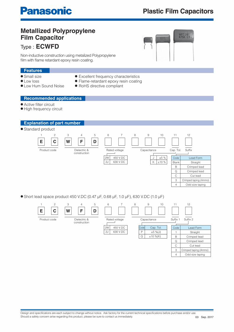
Design and specifications are each subject to change without notice. Ask factory for the current technical specifications before purchase and/or use.
Should a safety concern arise regarding this product, please be sure to contact us immediately.
Plastic Film Capacitors
1 2 3 4 5 6 7 8 9 11
E C W F D
12
Product code Dielectric &construction
Cap. Tol.Rated voltage Capacitance Suffix
10
Code
Blank
B
Q
C
3
4
Lead Form
Straight
Crimped lead
Crimped lead
Cut lead
Crimped taping (Ammo)
Odd size taping
J ±5 %
K ±10 %
2W 450 V.DC
2J 630 V.DC
1 2 3 4 5 6 7 8 9 11
E C W F D
12
Product code Dielectric &construction
Suffix 1Rated voltage Capacitance Suffix 2
10
Code
1
B
Q
C
3
4
Lead Form
Straight
Crimped lead
Crimped lead
Cut lead
Crimped taping (Ammo)
Odd size taping
P ±5 %(J)
Q ±10 %(K)
Code Cap. Tol.2W 450 V.DC
2J 630 V.DC
● Small size ● Excellent frequency characteristics● Low loss ● Flame-retardant epoxy resin coating● Low Hum Sound Noise ● RoHS directive compliant
● Active fi lter circuit● High frequency circuit
● Short lead space product 450 V.DC (0.47 μF, 0.68 μF, 1.0 μF), 630 V.DC (1.0 μF)
● Standard product
Non-inductive construction using metalized Polypropylene
fi lm with fl ame retardant epoxy resin coating.
Features
Metallized Polypropylene Film CapacitorType : ECWFD
Recommended applications
Explanation of part number
Sep. 201703

Design and specifications are each subject to change without notice. Ask factory for the current technical specifications before purchase and/or use.
Should a safety concern arise regarding this product, please be sure to contact us immediately.
Plastic Film Capacitors
Style ABP
F
H1
H0
P0
F
Style E
P
P0
H1
H0
Style F
F
P
H1
H0
P0
T max.
0d±0.05
Copper-clad
steel-wire
L max.
Marking
G m
ax.
H m
ax.
25 m
in.
F±1.0
Straight Crimped lead
(Suffix B)
L max.
H m
ax.
S±0.8
4.5±0
.5
Marking
Crimped lead
(Suffix Q)
Cut lead
(Suffix C)
L max.
S±0.8
Marking
H m
ax.
4.5±0
.5
4.5±
0.5
Marking
Type B Type D
Unit : mm
● Packing quantity : 100 pcs./bag
Category temp. range
(Including temperature-rise on unit surface)
450 V.DC – 40 °C to +110 °C
630 V.DC – 40 °C to +105 °C
Rated voltage
450 V.DC (Derating of rated voltage by 0.62%/°C at more than 85°C Peak to peak voltage applied on the capacitor should be less than 240 Vp-p, and zero to peak voltage should be less than 450 Vo-p.630 V.DC (Derating of rated voltage by 1.0%/°C at more than 85°C Peak to peak voltage applied on the capacitor should be less than 400 Vp-p, and zero to peak voltage should be less than 630 Vo-p.
Capacitance range450 V.DC 0.1 μF to 4.7 μF630 V.DC 0.047 μF to 4.7 μF
Capacitance tolerance ±5 %(J), ±10 %(K)Dissipation factor (tan d) tan d < 0.1 % ( 20 °C, 1 kHz )
Withstand voltage Between terminals:Rated voltage (V.DC)×150 %, 60 s
Insulation resistance (IR)450 V.DC
C < 0.33 μF : IR > 30000 MΩ (20 °C, 100 V.DC, 60 s)
C > 0.33 μF : IR > 10000 MΩ ∙ μF
630 V.DCC < 0.33 μF : IR > 9000 MΩ
(20 °C, 500 V.DC, 60 s)C > 0.33 μF : IR > 3000 MΩ ∙ μF
✽ In case of applying voltage in alternating current (50 Hz or 60 Hz sine wave) to a capacitor with DC rated voltage, please refer to the page of “Permissible voltage (R.M.S) in alternating current corresponding to DC rated voltage”.
● Taping style
✽ Refer to the page of taping specifications.
TypeRated
voltage(V.DC)
Capacitance range
(μF)
Taping stylePacking suffi x
AD AS AB B C D E F
ECWFD
450
0.10 to 0.39 ◯
Ammo
3
0.47, 0.68, 1.0 ◯ P3/Q3
0.10 to 0.39 ◯ 4
0.47, 0.68, 1.0 ◯ P4/Q4
0.47 to 2.2 ◯ 4
630
0.047 to 0.22 ◯ 4
0.27 to 0.82 ◯ 4
1.0 ◯ P4/Q4
● Taping style ● Lead spacing
Style Lead spacing
AB 5.0 mm
E 7.5 mm
F 7.5 mm
Packaging specifi cations for bulk package
Taping specifi cations for automatic insertion
Dimensions
Specifi cations
Sep. 201703

Design and specifications are each subject to change without notice. Ask factory for the current technical specifications before purchase and/or use.
Should a safety concern arise regarding this product, please be sure to contact us immediately.
Plastic Film Capacitors
Part No.Cap.(μF)
Dimensions (mm) Min. order Q'ty
Lmax.
Tmax.
H max.
F
SG
max.fd
Taping Bulk
StraightCrimped
lead(Suffix B)
Crimped lead
(Suffix Q)
Crimped lead
(Suffix B)
Crimped lead
(Suffix Q)5.0 mm 7.5 mm Straight
Crimped lead
ECWFD2W104◻( ) 0.10 12.6 4.5
–
13.9 13.9
–
7.5 10.0
–
0.6
1500 1400
–
1000
ECWFD2W124◻( ) 0.12 12.6 4.6 14.0 14.0 7.5 10.0 0.6
ECWFD2W154◻( ) 0.15 12.6 4.6 14.1 14.1 7.5 10.0 0.6
ECWFD2W184◻( ) 0.18 12.6 4.8 14.3 14.3 7.5 10.0 0.61400
1300
ECWFD2W224◻( ) 0.22 12.6 5.0 14.6 14.6 7.5 10.0 0.61200
ECWFD2W274◻( ) 0.27 12.6 5.3 15.0 15.0 7.5 10.0 0.6 1300
ECWFD2W334◻( ) 0.33 12.6 5.6 15.4 15.4 7.5 10.0 0.6 1200 1100
ECWFD2W394◻( ) 0.39 12.6 6.0 15.7 15.7 7.5 10.0 0.6 1100 1000
ECWFD2W474P( )ECWFD2W474Q( )
0.47 12.6 6.5 11.2 16.2 16.2 10.0 7.5 10.0 1.5 0.6 1000 900
1000
ECWFD2W474◻( ) 0.47 17.5 5.8 9.0 14.0 16.0 15.0 7.5 15.0 1.5 0.8 – 500
ECWFD2W564◻( ) 0.56 17.5 6.2 9.4 14.4 16.4 15.0 7.5 15.0 1.5 0.8 –
ECWFD2W684P( )ECWFD2W684Q( )
0.68 12.6 7.7 12.4 17.4 17.4 10.0 7.5 10.0 1.5 0.6 800 700
ECWFD2W684◻( ) 0.68 17.5 6.7 9.9 14.9 16.9 15.0 7.5 15.0 1.5 0.8 – 400
ECWFD2W824◻( ) 0.82 17.5 7.2 10.4 15.4 17.4 15.0 7.5 15.0 1.5 0.8 –
ECWFD2W105P( )ECWFD2W105Q( )
1.0 12.6 9.2 13.9 18.9 18.9 10.0 7.5 10.0 1.5 0.6 700 600
ECWFD2W105◻( ) 1.0 17.5 7.8 11.0 16.0 18.0 15.0 7.5 15.0 1.5 0.8
–
400
ECWFD2W125◻( ) 1.2 17.5 8.5 11.6 16.6 18.6 15.0 7.5 15.0 1.5 0.8
300ECWFD2W155◻( ) 1.5 17.5 9.3 12.5 17.5 19.5 15.0 7.5 15.0 1.5 0.8
ECWFD2W185◻( ) 1.8 17.5 10.1 13.3 18.3 20.3 15.0 7.5 15.0 1.5 0.8
ECWFD2W225◻( ) 2.2 17.5 11.1 14.3 19.3 21.3 15.0 7.5 15.0 1.5 0.8 200
ECWFD2W275◻( ) 2.7 25.3 9.0 13.7 18.7 20.7 22.5 15.0 22.5 1.5 0.8
–ECWFD2W335◻( ) 3.3 25.3 9.8 14.6 19.6 21.6 22.5 15.0 22.5 1.5 0.8
800ECWFD2W395◻( ) 3.9 25.3 10.7 15.4 20.4 22.4 22.5 15.0 22.5 1.5 0.8
ECWFD2W475◻( ) 4.7 25.3 11.7 16.4 21.4 23.4 22.5 15.0 22.5 1.5 0.8 600 600
● Rated voltage : 450 V.DC, Capacitance tolerance : ±5 %(J), ± 10 %(K),
Note) Part Number marked with ★ is Short Lead Space Product.
✽ ◻ : Capacitance tolerance code ( ) : Suffi x for lead crimped
★
★
★
Rating · Dimensions · Quantity
Sep. 201703
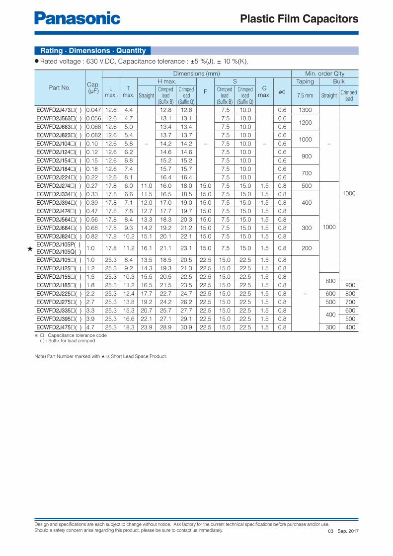
Design and specifications are each subject to change without notice. Ask factory for the current technical specifications before purchase and/or use.
Should a safety concern arise regarding this product, please be sure to contact us immediately.
Plastic Film Capacitors
● Rated voltage : 630 V.DC, Capacitance tolerance : ±5 %(J), ± 10 %(K),
Note) Part Number marked with ★ is Short Lead Space Product.
✽ ◻ : Capacitance tolerance code ( ) : Suffi x for lead crimped
Rating · Dimensions · Quantity
Part No.Cap.(μF)
Dimensions (mm) Min. order Q'ty
Lmax.
Tmax.
H max.
F
SG
max.fd
Taping Bulk
StraightCrimped
lead(Suffix B)
Crimped lead
(Suffix Q)
Crimped lead
(Suffix B)
Crimped lead
(Suffix Q)7.5 mm Straight
Crimped lead
ECWFD2J473◻( ) 0.047 12.6 4.4
–
12.8 12.8
–
7.5 10.0
–
0.6 1300
–
1000
ECWFD2J563◻( ) 0.056 12.6 4.7 13.1 13.1 7.5 10.0 0.61200
ECWFD2J683◻( ) 0.068 12.6 5.0 13.4 13.4 7.5 10.0 0.6
ECWFD2J823◻( ) 0.082 12.6 5.4 13.7 13.7 7.5 10.0 0.61000
ECWFD2J104◻( ) 0.10 12.6 5.8 14.2 14.2 7.5 10.0 0.6
ECWFD2J124◻( ) 0.12 12.6 6.2 14.6 14.6 7.5 10.0 0.6 900
ECWFD2J154◻( ) 0.15 12.6 6.8 15.2 15.2 7.5 10.0 0.6
ECWFD2J184◻( ) 0.18 12.6 7.4 15.7 15.7 7.5 10.0 0.6 700
ECWFD2J224◻( ) 0.22 12.6 8.1 16.4 16.4 7.5 10.0 0.6
ECWFD2J274◻( ) 0.27 17.8 6.0 11.0 16.0 18.0 15.0 7.5 15.0 1.5 0.8 500
1000
ECWFD2J334◻( ) 0.33 17.8 6.6 11.5 16.5 18.5 15.0 7.5 15.0 1.5 0.8
400ECWFD2J394◻( ) 0.39 17.8 7.1 12.0 17.0 19.0 15.0 7.5 15.0 1.5 0.8
ECWFD2J474◻( ) 0.47 17.8 7.8 12.7 17.7 19.7 15.0 7.5 15.0 1.5 0.8
ECWFD2J564◻( ) 0.56 17.8 8.4 13.3 18.3 20.3 15.0 7.5 15.0 1.5 0.8
300ECWFD2J684◻( ) 0.68 17.8 9.3 14.2 19.2 21.2 15.0 7.5 15.0 1.5 0.8
ECWFD2J824◻( ) 0.82 17.8 10.2 15.1 20.1 22.1 15.0 7.5 15.0 1.5 0.8
ECWFD2J105P( )ECWFD2J105Q( )
1.0 17.8 11.2 16.1 21.1 23.1 15.0 7.5 15.0 1.5 0.8 200
ECWFD2J105◻( ) 1.0 25.3 8.4 13.5 18.5 20.5 22.5 15.0 22.5 1.5 0.8
–
ECWFD2J125◻( ) 1.2 25.3 9.2 14.3 19.3 21.3 22.5 15.0 22.5 1.5 0.8
ECWFD2J155◻( ) 1.5 25.3 10.3 15.5 20.5 22.5 22.5 15.0 22.5 1.5 0.8 800
ECWFD2J185◻( ) 1.8 25.3 11.2 16.5 21.5 23.5 22.5 15.0 22.5 1.5 0.8 900
ECWFD2J225◻( ) 2.2 25.3 12.4 17.7 22.7 24.7 22.5 15.0 22.5 1.5 0.8 600 800
ECWFD2J275◻( ) 2.7 25.3 13.8 19.2 24.2 26.2 22.5 15.0 22.5 1.5 0.8 500 700
ECWFD2J335◻( ) 3.3 25.3 15.3 20.7 25.7 27.7 22.5 15.0 22.5 1.5 0.8 400
600
ECWFD2J395◻( ) 3.9 25.3 16.6 22.1 27.1 29.1 22.5 15.0 22.5 1.5 0.8 500
ECWFD2J475◻( ) 4.7 25.3 18.3 23.9 28.9 30.9 22.5 15.0 22.5 1.5 0.8 300 400
★
Sep. 201703

Design and specifications are each subject to change without notice. Ask factory for the current technical specifications before purchase and/or use.
Should a safety concern arise regarding this product, please be sure to contact us immediately.
Plastic Film Capacitors
1 2 3 4 5 6 7 8 9 11 12
E C W F E
Product code Dielectric &construction
SuffixCap. Tol.Rated voltage Capacitance
10
J ±5 %
K ±10 %
2W 450 V.DC
2J 630 V.DC
Code
Blank
A
Lead Form
Straight
Cut lead
1 2 3 4 5 6 7 8 9 11 12
E C W F E 2 W
Product code Dielectric &construction
SuffixCap. Tol.Rated voltage Capacitance
10
P ±5 %
Q ±10 %
2W 450 V.DC Code
1
A
Lead Form
Straight
Cut lead
● Small size● Excellent frequency characteristics● Low loss● Flame retardant plastic case and non-combustible resin● Low Hum Sound Noise● RoHS directive compliant
● Active fi lter circuit● High frequency circuit
● Standard
● Short lead space product (0.47 μF)
Features
Metallized Polypropylene Film CapacitorType : ECWFE
✽ In case of applying voltage in alternating current (50 Hz or 60 Hz sine wave) to a capacitor with DC rated voltage, please refer to the page of “Permissible voltage (R.M.S) in alternating current corresponding to DC rated voltage”.
Non-inductive construction using metalized Polypropylene
fi lm with fl ame retardant plastic case.
Category temp. range(Including temperature-rise on unit surface)
– 40 °C to +105 °C
Rated voltage
450 V.DC (Derating of rated voltage by 1.25 %/°C at more than 85 °C)Peak to peak voltage applied on the capacitor should be less than 240 Vp-p ,and zero to peak voltage should be less than 450 Vo-p.
630 V.DC ( Derating of rated voltage by 1.0%/°C at more than 85 °C)Peak to peak voltage applied on the capacitor should be less than400 Vp-p ,and zero to peak voltage should be less than 630 Vo-p.
Capacitance range450 V.DC 0.1 μF to 4.7 μF
630 V.DC 0.1 μF to 2.2 μF
Capacitance tolerance ±5 %(J), ±10 %(K)
Dissipation factor (tan d) tan d < 0.1 % (20 °C, 1 kHz)
Withstand voltage Between terminals : Rated voltage (V.DC)×150 % 60 s
Insulation resistance (IR)
450 V.DCC < 0.33 μF : IR > 30000 MΩ
(20 °C, 100 V.DC, 60 s)C > 0.33 μF : IR > 10000 MΩ ∙ μF
630 V.DCC < 0.33 μF : IR > 9000 MΩ
(20 °C, 500 V.DC, 60 s)C > 0.33 μF : IR > 3000 MΩ ∙ μF
Recommended applications
Specifi cations
Explanation of part number
Sep. 201702

Design and specifications are each subject to change without notice. Ask factory for the current technical specifications before purchase and/or use.
Should a safety concern arise regarding this product, please be sure to contact us immediately.
Plastic Film Capacitors
4.0±
0.5
Cut lead
(Suffix A)
Marking
Tin-plated copper-clad steel wire
0d±0.05
L±0.5 T±0.5
H±
0.5
F±0.4
20
min
.
Q+1.4–0.6
P(Lead location limits from center)
Marking example
W F E 2 W1 0 5 J
Note : Date code.
Unit : mm
● Rated voltage : 450 V.DC, Capacitance tolerance : ±5 %(J), ± 10 %(K),
● Rated voltage : 630 V.DC, Capacitance tolerance : ±5 %(J), ± 10 %(K),
Part No.Cap.(μF)
Dimensions (mm) Min. order Q'ty
L T H F fd P Q Straight Cut lead
ECWFE2W104◻( ) 0.10 13.0 5.0 10.5 10.0 0.6 0±0.8 1.5
1000
1000
ECWFE2W154◻( ) 0.15 13.0 5.0 10.5 10.0 0.6 0±0.8 1.5
ECWFE2W224◻( ) 0.22 13.0 6.0 12.0 10.0 0.6 0±0.8 1.5
ECWFE2W334◻( ) 0.33 13.0 6.0 12.0 10.0 0.6 0±0.8 1.5
ECWFE2W474P( )ECWFE2W474Q( ) 0.47 13.0 7.0 12.5 10.0 0.6 0±0.8 1.5
ECWFE2W474◻( ) 0.47 17.5 6.0 11.5 15.0 0.8 0±0.8 1.3
ECWFE2W684◻( ) 0.68 17.5 7.0 12.5 15.0 0.8 0±0.8 1.3
ECWFE2W105◻( ) 1.0 17.5 7.0 12.5 15.0 0.8 0±0.8 1.3
ECWFE2W155◻( ) 1.5 17.5 10.0 15.5 15.0 0.8 0±0.8 1.3 600
ECWFE2W225◻( ) 2.2 17.5 10.0 15.5 15.0 0.8 0±0.8 1.3
ECWFE2W335◻( ) 3.3 26.0 10.0 17.0 22.5 0.8 0±0.8 1.8 500 300
ECWFE2W475◻( ) 4.7 26.0 12.0 19.0 22.5 0.8 0±0.8 1.8 300 200
Part No.Cap.(μF)
Dimensions (mm) Min. order Q'ty
L T H F fd P Q Straight Cut lead
ECWFE2J104◻( ) 0.10 17.5 5.0 10.5 15.0 0.6 0±0.8 1.3
1000
1000ECWFE2J154◻( ) 0.15 17.5 6.0 11.5 15.0 0.6 0±0.8 1.3
ECWFE2J224◻( ) 0.22 17.5 7.0 12.5 15.0 0.6 0±0.8 1.3
ECWFE2J334◻( ) 0.33 17.5 8.5 14.5 15.0 0.6 0±0.8 1.3 800
ECWFE2J474◻( ) 0.47 17.5 10.0 15.5 15.0 0.6 0±0.8 1.3 600
ECWFE2J684◻( ) 0.68 17.5 11.0 17.5 15.0 0.6 0±0.8 1.3 600
ECWFE2J105◻( ) 1.0 26.0 10.0 17.0 22.5 0.8 0±0.8 1.8 500 300
ECWFE2J155◻( ) 1.5 26.0 12.0 19.0 22.5 0.8 0±0.8 1.8 300 200
ECWFE2J225◻( ) 2.2 26.0 16.0 23.0 22.5 0.8 0±0.8 1.8 200
✽ ◻ : Capacitance tolerance code ( ) : Suffi x for lead crimped
✽ ◻ : Capacitance tolerance code ( ) : Suffi x for lead crimped
Note) Part Number marked with ★ is Short Lead Space Product.
★
Dimensions
Rating · Dimensions · Quantity
Sep. 201702

Design and specifications are each subject to change without notice. Ask factory for the current technical specifications before purchase and/or use.
Should a safety concern arise regarding this product, please be sure to contact us immediately.
Plastic Film Capacitors
1 2 3 4 5 6 7 8 9 11
E C W H
12
Product code Dielectric &construction
SuffixRated voltage Capacitance SuffixCap. Tol.
10
V
Code
Blank
B
C
Lead Form
Straight
Crimped lead
Cut lead
H ±3 %
J ±5 %
10 1000 V.DC
12 1250 V.DC
16 1600 V.DC
20 2000 V.DC
1 2 3 4 5 6 7 8 9 11
E C W H
12
Product code Dielectric &construction
Cap. Tol.Rated voltage Capacitance SuffixSuffix
10
VR
● Low-loss● Excellent electrical characteristics● Flame retardant epoxy resin coating● RoHS directive compliant
● High frequency high voltage circuit
(General resonance, inverter circuit)
● Odd size taping
Non-inductive construction using metallized polypropylene fi lm
with fl ame retardant epoxy resin coating.
Features
Metallized Polypropylene Film CapacitorType : ECWH(V)
Category temp. range
(Including temperature-rise on unit surface)– 40 °C to +105 °C
Rated voltage
1000 V.DC, 1250 V.DC (1000 Vp-p)
1600 V.DC (1200 Vp-p), 2000 V.DC (1500 Vp-p)
(Derating of rated voltage by 1.25 %/°C at more than 85 °C)
Capacitance range
1000 V.DC 0.0075 μF to 0.10 μF
1250 V.DC 0.0036 μF to 0.10 μF
1600 V.DC 0.0013 μF to 0.056 μF
2000 V.DC 0.001 μF to 0.015 μF
Capacitance tolerance ±3 %(H), ±5 %(J)
Dissipation factor (tan d)tan d < 0.1 % (20 °C, 1 kHz)
tan d < 0.2 % (20 °C, 10 kHz)
Withstand voltageBetween terminals : Rated volt. (V.DC)×150 %, 60 s
Between terminals to enclosure : 1500 V.AC 60 s
Insulation resistance (IR) IR > 30000 MΩ (20 °C, 500 V.DC, 60 s)
✽ In case of applying voltage in alternating current (50 Hz or 60 Hz sine wave) to a capacitor with DC rated voltage, please refer to the page of “Permissible voltage (R.M.S) in alternating current corresponding to DC rated voltage”.
Recommended applications
Explanation of part number
Specifi cations
Sep. 201702

Design and specifications are each subject to change without notice. Ask factory for the current technical specifications before purchase and/or use.
Should a safety concern arise regarding this product, please be sure to contact us immediately.
Plastic Film Capacitors
L max.
Marking
1.5
ma
x.
H m
ax.
25
min
.F±1.25
T max.
00.80±0.05
Copper wire
L max.
H m
ax.
S±0.8
4.5±
0.5
Marking
Crimped lead
(Suffix B)Straight
4.5±
0.5
Marking
Cut lead
(Suffix C)
F
Style E
P
P0
H1
H0
● Packing quantity : 100 pcs./bag
Packaging specifi cations for bulk package
Unit : mm
● Taping style
TypeRated voltage
(V.DC)Capacitance range
(μF)
Taping stylePacking suffi x
AD AS B C D E
ECWH(V)
1000 0.0075 to 0.10 ◯
Ammo
R( ) V
1250 0.0036 to 0.051 ◯ R( ) V
1600 0.0013 to 0.020 ◯ R( ) V
2000 0.0010 to 0.015 ◯ R( ) V
● Taping style ● Lead spacing
Style Lead spacing
E 7.5 mm
✽ See the column “Rating · Dimensions · Quantity” for packing quantity
Dimensions
Taping specifi cations for automatic insertion
✽ Refer to the page of taping specifications.
Sep. 201702
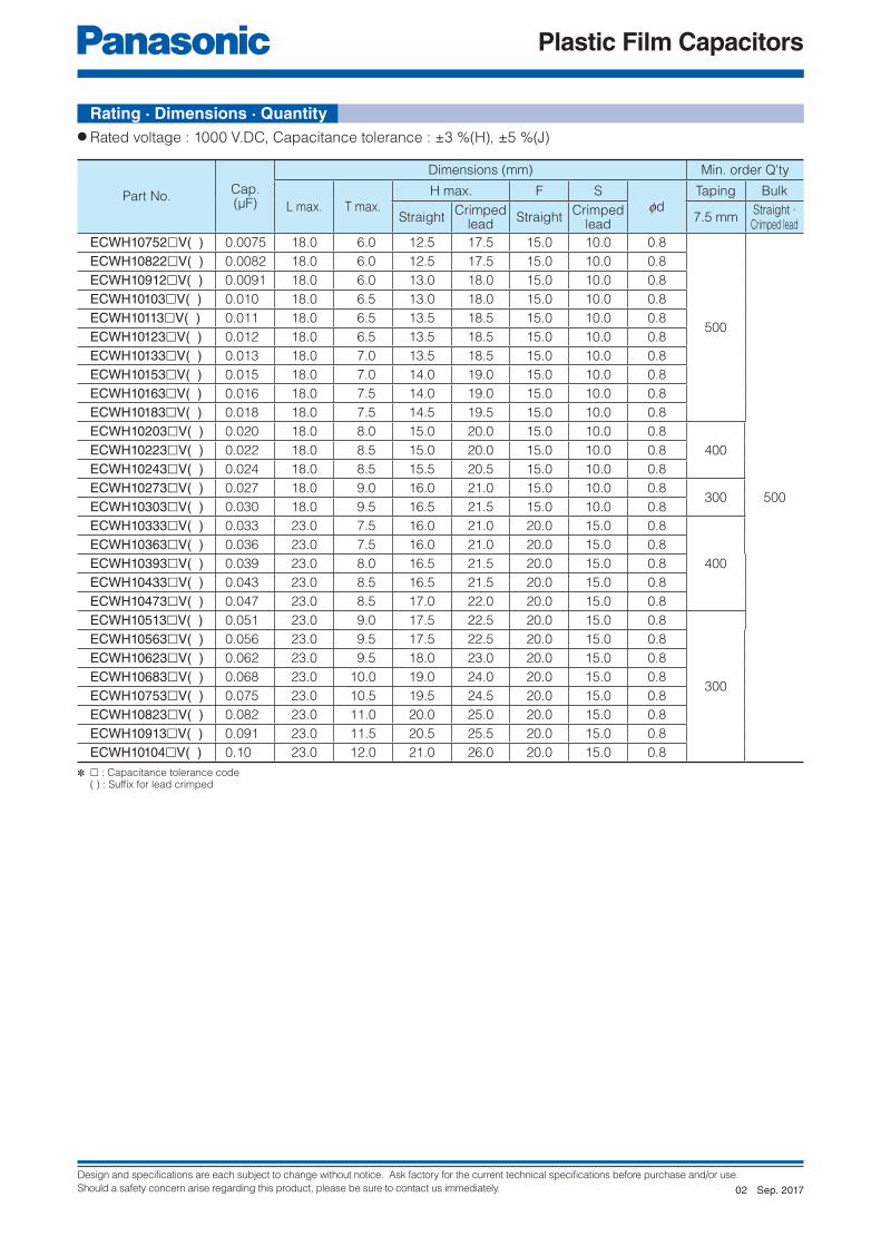
Design and specifications are each subject to change without notice. Ask factory for the current technical specifications before purchase and/or use.
Should a safety concern arise regarding this product, please be sure to contact us immediately.
Plastic Film Capacitors
● Rated voltage : 1000 V.DC, Capacitance tolerance : ±3 %(H), ±5 %(J)
✽ ◻ : Capacitance tolerance code ( ) : Suffi x for lead crimped
Part No.Cap.(μF)
Dimensions (mm) Min. order Q'ty
L max. T max.H max. F S
fdTaping Bulk
StraightCrimped
leadStraight
Crimped lead
7.5 mmStraight ·
Crimped lead
ECWH10752◻V( ) 0.0075 18.0 6.0 12.5 17.5 15.0 10.0 0.8
500
500
ECWH10822◻V( ) 0.0082 18.0 6.0 12.5 17.5 15.0 10.0 0.8
ECWH10912◻V( ) 0.0091 18.0 6.0 13.0 18.0 15.0 10.0 0.8
ECWH10103◻V( ) 0.010 18.0 6.5 13.0 18.0 15.0 10.0 0.8
ECWH10113◻V( ) 0.011 18.0 6.5 13.5 18.5 15.0 10.0 0.8
ECWH10123◻V( ) 0.012 18.0 6.5 13.5 18.5 15.0 10.0 0.8
ECWH10133◻V( ) 0.013 18.0 7.0 13.5 18.5 15.0 10.0 0.8
ECWH10153◻V( ) 0.015 18.0 7.0 14.0 19.0 15.0 10.0 0.8
ECWH10163◻V( ) 0.016 18.0 7.5 14.0 19.0 15.0 10.0 0.8
ECWH10183◻V( ) 0.018 18.0 7.5 14.5 19.5 15.0 10.0 0.8
ECWH10203◻V( ) 0.020 18.0 8.0 15.0 20.0 15.0 10.0 0.8
400ECWH10223◻V( ) 0.022 18.0 8.5 15.0 20.0 15.0 10.0 0.8
ECWH10243◻V( ) 0.024 18.0 8.5 15.5 20.5 15.0 10.0 0.8
ECWH10273◻V( ) 0.027 18.0 9.0 16.0 21.0 15.0 10.0 0.8300
ECWH10303◻V( ) 0.030 18.0 9.5 16.5 21.5 15.0 10.0 0.8
ECWH10333◻V( ) 0.033 23.0 7.5 16.0 21.0 20.0 15.0 0.8
400
ECWH10363◻V( ) 0.036 23.0 7.5 16.0 21.0 20.0 15.0 0.8
ECWH10393◻V( ) 0.039 23.0 8.0 16.5 21.5 20.0 15.0 0.8
ECWH10433◻V( ) 0.043 23.0 8.5 16.5 21.5 20.0 15.0 0.8
ECWH10473◻V( ) 0.047 23.0 8.5 17.0 22.0 20.0 15.0 0.8
ECWH10513◻V( ) 0.051 23.0 9.0 17.5 22.5 20.0 15.0 0.8
300
ECWH10563◻V( ) 0.056 23.0 9.5 17.5 22.5 20.0 15.0 0.8
ECWH10623◻V( ) 0.062 23.0 9.5 18.0 23.0 20.0 15.0 0.8
ECWH10683◻V( ) 0.068 23.0 10.0 19.0 24.0 20.0 15.0 0.8
ECWH10753◻V( ) 0.075 23.0 10.5 19.5 24.5 20.0 15.0 0.8
ECWH10823◻V( ) 0.082 23.0 11.0 20.0 25.0 20.0 15.0 0.8
ECWH10913◻V( ) 0.091 23.0 11.5 20.5 25.5 20.0 15.0 0.8
ECWH10104◻V( ) 0.10 23.0 12.0 21.0 26.0 20.0 15.0 0.8
Rating · Dimensions · Quantity
Sep. 201702

Design and specifications are each subject to change without notice. Ask factory for the current technical specifications before purchase and/or use.
Should a safety concern arise regarding this product, please be sure to contact us immediately.
Plastic Film Capacitors
● Rated voltage : 1250 V.DC, Capacitance tolerance : ±3 %(H), ±5 %(J)
✽ ◻ : Capacitance tolerance code ( ) : Suffi x for lead crimped
Part No.Cap.(μF)
Dimensions (mm) Min. order Q'ty
L max. T max.H max. F S
fdTaping Bulk
StraightCrimped
leadStraight
Crimped lead
7.5 mm StraightCrimped
lead
ECWH12362◻V( ) 0.0036 18.0 6.0 12.5 17.5 15.0 10.0 0.8
500
500
500
ECWH12392◻V( ) 0.0039 18.0 6.0 12.5 17.5 15.0 10.0 0.8
ECWH12432◻V( ) 0.0043 18.0 6.0 13.0 18.0 15.0 10.0 0.8
ECWH12472◻V( ) 0.0047 18.0 6.0 13.0 18.0 15.0 10.0 0.8
ECWH12512◻V( ) 0.0051 18.0 6.5 13.0 18.0 15.0 10.0 0.8
ECWH12562◻V( ) 0.0056 18.0 6.5 13.5 18.5 15.0 10.0 0.8
ECWH12622◻V( ) 0.0062 18.0 6.5 13.5 18.5 15.0 10.0 0.8
ECWH12682◻V( ) 0.0068 18.0 7.0 13.5 18.5 15.0 10.0 0.8
ECWH12752◻V( ) 0.0075 18.0 7.0 14.0 19.0 15.0 10.0 0.8
ECWH12822◻V( ) 0.0082 18.0 7.5 14.0 19.0 15.0 10.0 0.8
ECWH12912◻V( ) 0.0091 18.0 7.5 14.5 19.5 15.0 10.0 0.8
ECWH12103◻V( ) 0.010 18.0 8.0 15.0 20.0 15.0 10.0 0.8
400
ECWH12113◻V( ) 0.011 18.0 8.5 15.0 20.0 15.0 10.0 0.8
ECWH12123◻V( ) 0.012 18.0 8.5 15.5 20.5 15.0 10.0 0.8
ECWH12133◻V( ) 0.013 18.0 9.0 15.5 20.5 15.0 10.0 0.8
ECWH12153◻V( ) 0.015 18.0 9.5 16.0 21.0 15.0 10.0 0.8
ECWH12163◻V( ) 0.016 23.0 7.5 16.0 21.0 20.0 15.0 0.8500
ECWH12183◻V( ) 0.018 23.0 7.5 16.0 21.0 20.0 15.0 0.8
ECWH12203◻V( ) 0.020 23.0 8.0 16.5 21.5 20.0 15.0 0.8
400
ECWH12223◻V( ) 0.022 23.0 8.5 16.5 21.5 20.0 15.0 0.8
ECWH12243◻V( ) 0.024 23.0 8.5 17.0 22.0 20.0 15.0 0.8
ECWH12273◻V( ) 0.027 23.0 9.0 17.5 22.5 20.0 15.0 0.8
ECWH12303◻V( ) 0.030 23.0 9.5 18.0 23.0 20.0 15.0 0.8
ECWH12333◻V( ) 0.033 23.0 10.0 18.5 23.5 20.0 15.0 0.8
300
ECWH12363◻V( ) 0.036 23.0 10.0 19.0 24.0 20.0 15.0 0.8
ECWH12393◻V( ) 0.039 23.0 10.5 19.5 24.5 20.0 15.0 0.8
ECWH12433◻V( ) 0.043 23.0 11.0 20.0 25.0 20.0 15.0 0.8
ECWH12473◻V( ) 0.047 23.0 11.5 20.5 25.5 20.0 15.0 0.8
ECWH12513◻V( ) 0.051 23.0 12.0 21.0 26.0 20.0 15.0 0.8
ECWH12563◻V( ) 0.056 28.0 11.5 20.0 25.0 25.0 17.5 0.8
−
ECWH12623◻V( ) 0.062 28.0 12.0 21.0 26.0 25.0 17.5 0.8
ECWH12683◻V( ) 0.068 28.0 12.5 21.5 26.5 25.0 17.5 0.8
ECWH12753◻V( ) 0.075 28.0 13.5 22.0 27.0 25.0 17.5 0.8
ECWH12823◻V( ) 0.082 28.0 14.0 22.5 27.5 25.0 17.5 0.8
ECWH12913◻V( ) 0.091 28.0 14.5 23.0 28.0 25.0 17.5 0.8400
ECWH12104◻V( ) 0.10 28.0 15.5 24.0 29.0 25.0 17.5 0.8
Rating · Dimensions · Quantity
Sep. 201702

Design and specifications are each subject to change without notice. Ask factory for the current technical specifications before purchase and/or use.
Should a safety concern arise regarding this product, please be sure to contact us immediately.
Plastic Film Capacitors
✽ ◻ : Capacitance tolerance code ( ) : Suffi x for lead crimped
Part No.Cap.(μF)
Dimensions (mm) Min. order Q'ty
L max. T max.H max. F S
fdTaping Bulk
StraightCrimped
leadStraight
Crimped lead
7.5 mm StraightCrimped
lead
ECWH16132◻V( ) 0.0013 18.0 6.5 13.0 18.0 15.0 10.0 0.8
500
500
500
ECWH16152◻V( ) 0.0015 18.0 6.5 13.5 18.5 15.0 10.0 0.8
ECWH16162◻V( ) 0.0016 18.0 7.0 13.5 18.5 15.0 10.0 0.8
ECWH16182◻V( ) 0.0018 18.0 7.0 14.0 19.0 15.0 10.0 0.8
ECWH16202◻V( ) 0.0020 18.0 7.0 14.0 19.0 15.0 10.0 0.8
ECWH16222◻V( ) 0.0022 18.0 6.5 13.5 18.5 15.0 10.0 0.8
ECWH16242◻V( ) 0.0024 18.0 7.0 13.5 18.5 15.0 10.0 0.8
ECWH16272◻V( ) 0.0027 18.0 7.0 14.0 19.0 15.0 10.0 0.8
ECWH16302◻V( ) 0.003 18.0 7.5 14.0 19.0 15.0 10.0 0.8400
ECWH16332◻V( ) 0.0033 18.0 7.5 14.5 19.5 15.0 10.0 0.8
ECWH16362◻V( ) 0.0036 18.0 7.0 13.5 18.5 15.0 10.0 0.8
500
ECWH16392◻V( ) 0.0039 18.0 7.0 14.0 19.0 15.0 10.0 0.8
ECWH16432◻V( ) 0.0043 18.0 7.0 14.0 19.0 15.0 10.0 0.8
ECWH16472◻V( ) 0.0047 23.0 6.5 14.5 19.5 20.0 15.0 0.8
ECWH16512◻V( ) 0.0051 23.0 6.5 15.0 20.0 20.0 15.0 0.8
ECWH16562◻V( ) 0.0056 23.0 6.5 15.0 20.0 20.0 15.0 0.8
ECWH16622◻V( ) 0.0062 23.0 7.0 15.0 20.0 20.0 15.0 0.8
ECWH16682◻V( ) 0.0068 23.0 7.0 15.5 20.5 20.0 15.0 0.8
ECWH16752◻V( ) 0.0075 23.0 7.5 15.5 20.5 20.0 15.0 0.8
400
ECWH16822◻V( ) 0.0082 23.0 7.5 16.0 21.0 20.0 15.0 0.8
ECWH16912◻V( ) 0.0091 23.0 8.0 16.0 21.0 20.0 15.0 0.8
ECWH16103◻V( ) 0.010 23.0 8.0 16.5 21.5 20.0 15.0 0.8
ECWH16113◻V( ) 0.011 23.0 8.5 17.0 22.0 20.0 15.0 0.8
ECWH16123◻V( ) 0.012 23.0 9.0 17.0 22.0 20.0 15.0 0.8
300
ECWH16133◻V( ) 0.013 23.0 9.0 17.5 22.5 20.0 15.0 0.8
ECWH16153◻V( ) 0.015 23.0 9.5 18.0 23.0 20.0 15.0 0.8
ECWH16163◻V( ) 0.016 23.0 10.0 18.5 23.5 20.0 15.0 0.8
ECWH16183◻V( ) 0.018 23.0 10.5 19.5 24.5 20.0 15.0 0.8
ECWH16203◻V( ) 0.020 23.0 11.0 20.0 25.0 20.0 15.0 0.8
ECWH16223◻V( ) 0.022 28.0 9.5 18.0 23.0 25.0 17.5 0.8
−
ECWH16243◻V( ) 0.024 28.0 10.0 18.5 23.5 25.0 17.5 0.8
ECWH16273◻V( ) 0.027 28.0 10.5 19.5 24.5 25.0 17.5 0.8
ECWH16303◻V( ) 0.030 28.0 11.0 20.0 25.0 25.0 17.5 0.8
ECWH16333◻V( ) 0.033 28.0 11.5 20.5 25.5 25.0 17.5 0.8
ECWH16363◻V( ) 0.036 28.0 12.5 21.5 26.5 25.0 17.5 0.8
ECWH16393◻V( ) 0.039 28.0 13.5 22.0 27.0 25.0 17.5 0.8
ECWH16433◻V( ) 0.043 28.0 14.5 22.5 27.5 25.0 17.5 0.8
ECWH16473◻V( ) 0.047 28.0 15.0 23.5 28.5 25.0 17.5 0.8
ECWH16513◻V( ) 0.051 28.0 15.5 24.0 29.0 25.0 17.5 0.8400
ECWH16563◻V( ) 0.056 28.0 16.0 24.5 29.5 25.0 17.5 0.8
● Rated voltage : 1600 V.DC, Capacitance tolerance : ±3 %(H), ±5 %(J)
Rating · Dimensions · Quantity
Sep. 201702

Design and specifications are each subject to change without notice. Ask factory for the current technical specifications before purchase and/or use.
Should a safety concern arise regarding this product, please be sure to contact us immediately.
Plastic Film Capacitors
✽ ◻ : Capacitance tolerance code ( ) : Suffi x for lead crimped
Part No.Cap.(μF)
Dimensions (mm) Min. order Q'ty
L max. T max.H max. F S
fdTaping Bulk
StraightCrimped
leadStraight
Crimped lead
7.5 mmStraight ·
Crimped lead
ECWH20102◻V( ) 0.0010 18.0 6.5 13.5 18.5 15.0 10.0 0.8
500
500
ECWH20112◻V( ) 0.0011 18.0 6.5 13.5 18.5 15.0 10.0 0.8
ECWH20122◻V( ) 0.0012 18.0 7.0 13.5 18.5 15.0 10.0 0.8
ECWH20132◻V( ) 0.0013 18.0 7.0 14.0 19.0 15.0 10.0 0.8
ECWH20152◻V( ) 0.0015 18.0 7.5 14.0 19.0 15.0 10.0 0.8
400
ECWH20162◻V( ) 0.0016 18.0 7.5 14.5 19.5 15.0 10.0 0.8
ECWH20182◻V( ) 0.0018 18.0 8.0 14.5 19.5 15.0 10.0 0.8
ECWH20202◻V( ) 0.0020 18.0 8.0 15.0 20.0 15.0 10.0 0.8
ECWH20222◻V( ) 0.0022 18.0 8.5 15.0 20.0 15.0 10.0 0.8
ECWH20242◻V( ) 0.0024 18.0 8.5 15.5 20.5 15.0 10.0 0.8
ECWH20272◻V( ) 0.0027 18.0 9.0 16.0 21.0 15.0 10.0 0.8300
ECWH20302◻V( ) 0.0030 18.0 9.5 16.0 21.0 15.0 10.0 0.8
ECWH20332◻V( ) 0.0033 18.0 8.5 15.5 20.5 15.0 10.0 0.8 400
ECWH20362◻V( ) 0.0036 18.0 9.0 15.5 20.5 15.0 10.0 0.8
300ECWH20392◻V( ) 0.0039 18.0 9.0 16.0 21.0 15.0 10.0 0.8
ECWH20432◻V( ) 0.0043 18.0 9.5 16.0 21.0 15.0 10.0 0.8
ECWH20472◻V( ) 0.0047 23.0 7.0 15.5 20.5 20.0 15.0 0.8 500
ECWH20512◻V( ) 0.0051 23.0 7.5 16.0 21.0 20.0 15.0 0.8
400ECWH20562◻V( ) 0.0056 23.0 7.5 16.0 21.0 20.0 15.0 0.8
ECWH20622◻V( ) 0.0062 23.0 8.0 16.5 21.5 20.0 15.0 0.8
ECWH20682◻V( ) 0.0068 23.0 8.5 16.5 21.5 20.0 15.0 0.8
ECWH20752◻V( ) 0.0075 23.0 9.5 18.0 23.0 20.0 15.0 0.8
300
ECWH20822◻V( ) 0.0082 23.0 10.0 18.0 23.0 20.0 15.0 0.8
ECWH20912◻V( ) 0.0091 23.0 10.0 19.0 24.0 20.0 15.0 0.8
ECWH20103◻V( ) 0.010 23.0 10.5 19.5 24.5 20.0 15.0 0.8
ECWH20113◻V( ) 0.011 23.0 11.0 20.0 25.0 20.0 15.0 0.8
ECWH20123◻V( ) 0.012 23.0 11.5 20.5 25.5 20.0 15.0 0.8
ECWH20133◻V( ) 0.013 23.0 12.0 21.0 26.0 20.0 15.0 0.8
ECWH20153◻V( ) 0.015 23.0 12.0 21.5 26.5 20.0 15.0 0.8
● Rated voltage : 2000 V.DC, Capacitance tolerance : ±3 %(H), ±5 %(J)
Rating · Dimensions · Quantity
Sep. 201702

Design and specifications are each subject to change without notice. Ask factory for the current technical specifications before purchase and/or use.
Should a safety concern arise regarding this product, please be sure to contact us immediately.
Plastic Film Capacitors
1 2 3 4 5 6 7 8 9 11
E C W H 8
Product code Dielectric &construction
SuffixRated voltage Capacitance SuffixCap. Tol.
10
AH
Code
Blank
B
Q
C
Lead Form
Straight
Crimped lead
Crimped lead
Cut lead
H ±3 %8 800 V.DC
1 2 3 4 5 6 7 8 9 11
E C W H 3 C
12
Product code Dielectric &construction
Rated voltage Cap. Tol.Capacitance Suffix
10
Code
Blank
B
Q
C
4
Lead Form
Straight
Crimped lead
Crimped lead
Cut lead
Odd size taping
H ±3 %
J ±5 %
3C 1600 V.DC
A
1 2 3 4 5 6 7 8 9 11
E C W H 8
Product code Dielectric &construction
Cap. Tol.Rated voltage Capacitance SuffixSuffix
10
H AR
● Small size● Excellent electrical characteristics● Low loss● Low Hum Sound Noise● Flame retardant epoxy resin coating● RoHS directive compliant
● General resonance circuit
● Rated voltage 800 V.DC (Odd size taping)
● Rated voltage 800 V.DC (Bulk)
● Rated voltage 1600 V.DC
Non-inductive construction using metallized polypropylene fi lm
with fl ame retardant epoxy resin coating
Features
Metallized Polypropylene Film CapacitorType : ECWH(A)
Recommended applications
Explanation of part number
Sep. 201702
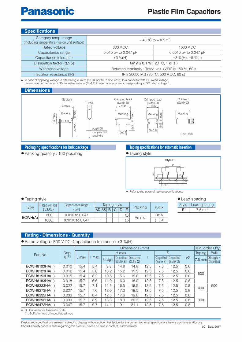
Design and specifications are each subject to change without notice. Ask factory for the current technical specifications before purchase and/or use.
Should a safety concern arise regarding this product, please be sure to contact us immediately.
Plastic Film Capacitors
L max.
Marking
1.5
ma
x.
H m
ax.
25
min
.
F±1.0
T max.
0d±0.05
Copper-clad
steel-wire
L max.
H m
ax.
S±0.84.5
±0.5
Marking
Crimped lead
(Suffix B)Straight
4.5±0
.5
Marking
Cut lead
(Suffix C)Crimped lead
(Suffix Q)L max.
S±0.8
Marking
H m
ax.
4.5±0
.5
F
Style E
P
P0
H1
H0
Unit : mm
● Packing quantity : 100 pcs./bag
✽ Refer to the page of taping specifications.
Taping specifi cations for automatic insertion● Taping style
TypeRated voltage
(V.DC)Capacitance range
(μF)
Taping stylePacking suffi x
AD AS B C D E
ECWH(A) 800 0.010 to 0.047 ◯
AmmoRHA
1600 0.0010 to 0.047 ◯ ( ) 4
● Taping style ● Lead spacing
Style Lead spacing
E 7.5 mm
Category temp. range
(Including temperature-rise on unit surface)– 40 °C to +105 °C
Rated voltage 800 V.DC 1600 V.DC
Capacitance range 0.010 μF to 0.047 μF 0.0010 μF to 0.047 μF
Capacitance tolerance ±3 %(H) ±3 %(H), ±5 %(J)
Dissipation factor (tan d) tan d < 0.1 % ( 20 °C, 1 kHz )
Withstand voltage Between terminals : Rated volt. (V.DC)×150 %, 60 s
Insulation resistance (IR) IR > 30000 MΩ (20 °C, 500 V.DC, 60 s)
✽ In case of applying voltage in alternating current (50 Hz or 60 Hz sine wave) to a capacitor with DC rated voltage, please refer to the page of “Permissible voltage (R.M.S) in alternating current corresponding to DC rated voltage”.
Part No.Cap.(μF)
Dimensions (mm) Min. order Q'ty
L max. T max.H max.
FS
fdTaping Bulk
StraightCrimped lead(Suffix B)
Crimped lead(Suffix Q)
Crimped lead(Suffix B)
Crimped lead(Suffix Q)
7.5 mmStraight ·Crimped lead
ECWH8103HA( ) 0.010 15.4 5.4 9.8 14.8 14.8 12.5 7.5 12.5 0.6
500
500
ECWH8123HA( ) 0.012 15.4 5.8 10.2 15.2 15.2 12.5 7.5 12.5 0.6
ECWH8153HA( ) 0.015 15.4 6.2 10.6 15.6 15.6 12.5 7.5 12.5 0.6
ECWH8183HA( ) 0.018 15.7 6.6 11.0 16.0 18.0 12.5 7.5 12.5 0.8
ECWH8223HA( ) 0.022 15.7 7.1 11.5 16.5 18.5 12.5 7.5 12.5 0.8400
ECWH8273HA( ) 0.027 15.7 7.6 12.0 17.0 19.0 12.5 7.5 12.5 0.8
ECWH8333HA( ) 0.033 15.7 8.4 12.8 17.8 19.8 12.5 7.5 12.5 0.8
300ECWH8393HA( ) 0.039 15.7 8.9 13.3 18.3 20.3 12.5 7.5 12.5 0.8
ECWH8473HA( ) 0.047 15.7 9.7 14.1 19.1 21.1 12.5 7.5 12.5 0.8
✽ H : Capacitance tolerance code ( ) : Suffi x for lead crimped taped type
● Rated voltage : 800 V.DC, Capacitance tolerance : ±3 %(H)
Dimensions
Packaging specifi cations for bulk package
Specifi cations
Rating · Dimensions · Quantity
Sep. 201702

Design and specifications are each subject to change without notice. Ask factory for the current technical specifications before purchase and/or use.
Should a safety concern arise regarding this product, please be sure to contact us immediately.
Plastic Film Capacitors
● Rated voltage : 1600 V.DC, Capacitance tolerance : ±3 %(H), ±5 %(J)
✽ ◻ : Capacitance tolerance code ( ) : Suffi x for lead crimped taped type
Part No.Cap.(μF)
Dimensions (mm) Min. order Q'ty
L max. T max.
H max.
F
S
fd
Taping Bulk
StraightCrimped lead(Suffix B)
Crimped lead(Suffix Q)
Crimped lead(Suffix B)
Crimped lead(Suffix Q)
7.5 mm StraightCrimped
lead
ECWHA3C102◻( ) 0.0010 17.8 5.2
−
13.0 13.0
−
10.0 15.0 0.6600
−
1000
ECWHA3C112◻( ) 0.0011 17.8 5.4 13.1 13.1 10.0 15.0 0.6
ECWHA3C122◻( ) 0.0012 17.8 5.5 13.2 13.2 10.0 15.0 0.6
500
ECWHA3C132◻( ) 0.0013 17.8 5.7 13.4 13.4 10.0 15.0 0.6
ECWHA3C152◻( ) 0.0015 17.8 5.9 13.7 13.7 10.0 15.0 0.6
ECWHA3C162◻( ) 0.0016 17.8 6.1 13.9 13.9 10.0 15.0 0.6
ECWHA3C182◻( ) 0.0018 17.8 6.4 14.1 14.1 10.0 15.0 0.6
ECWHA3C202◻( ) 0.0020 17.8 6.6 14.3 14.3 10.0 15.0 0.6
400ECWHA3C222◻( ) 0.0022 17.8 6.7 14.5 14.5 10.0 15.0 0.6
ECWHA3C242◻( ) 0.0024 17.8 7.0 14.7 14.7 10.0 15.0 0.6
ECWHA3C272◻( ) 0.0027 17.8 5.2 13.0 13.0 10.0 15.0 0.6 600
ECWHA3C302◻( ) 0.0030 17.8 5.5 13.2 13.2 10.0 15.0 0.6
500
ECWHA3C332◻( ) 0.0033 17.8 5.6 13.4 13.4 10.0 15.0 0.6
ECWHA3C362◻( ) 0.0036 17.8 5.7 13.5 13.5 10.0 15.0 0.6
ECWHA3C392◻( ) 0.0039 17.8 6.0 13.8 13.8 10.0 15.0 0.6
ECWHA3C432◻( ) 0.0043 17.8 6.2 13.9 13.9 10.0 15.0 0.6
ECWHA3C472◻( ) 0.0047 17.8 6.4 9.1 14.1 14.1 15.0 10.0 15.0 0.6
1000
ECWHA3C512◻( ) 0.0051 17.8 6.6 9.4 14.4 14.4 15.0 10.0 15.0 0.6
400ECWHA3C562◻( ) 0.0056 17.8 6.8 9.6 14.6 14.6 15.0 10.0 15.0 0.6
ECWHA3C622◻( ) 0.0062 17.8 7.1 9.8 14.8 14.8 15.0 10.0 15.0 0.6
ECWHA3C682◻( ) 0.0068 17.8 6.1 12.1 17.1 17.1 15.0 10.0 15.0 0.6 500
ECWHA3C752◻( ) 0.0075 17.8 6.5 12.4 17.4 17.4 15.0 10.0 15.0 0.6
400ECWHA3C822◻( ) 0.0082 17.8 6.8 12.7 17.7 17.7 15.0 10.0 15.0 0.6
ECWHA3C912◻( ) 0.0091 17.8 7.1 13.0 18.0 18.0 15.0 10.0 15.0 0.6
ECWHA3C103◻( ) 0.010 20.3 6.4 12.3 17.3 17.3 17.5 10.0 17.5 0.6 500
ECWHA3C113◻( ) 0.011 20.3 6.6 12.5 17.5 17.5 17.5 10.0 17.5 0.6
400
ECWHA3C123◻( ) 0.012 20.3 6.8 12.8 17.8 17.8 17.5 10.0 17.5 0.6
ECWHA3C133◻( ) 0.013 20.3 7.1 13.0 18.0 18.0 17.5 10.0 17.5 0.6
ECWHA3C153◻( ) 0.015 20.3 7.6 13.5 18.5 18.5 17.5 10.0 17.5 0.6
ECWHA3C163◻( ) 0.016 20.3 7.9 13.8 18.8 18.8 17.5 10.0 17.5 0.6
ECWHA3C183◻( ) 0.018 20.6 8.2 14.1 19.1 21.1 17.5 10.0 17.5 0.8
300
ECWHA3C203◻( ) 0.020 20.6 8.7 14.6 19.6 21.6 17.5 10.0 17.5 0.8
800
ECWHA3C223◻( ) 0.022 20.6 9.1 15.0 20.0 22.0 17.5 10.0 17.5 0.8
ECWHA3C243◻( ) 0.024 20.6 9.6 15.4 20.4 22.4 17.5 10.0 17.5 0.8
ECWHA3C273◻( ) 0.027 20.6 10.0 15.9 20.9 22.9 17.5 10.0 17.5 0.8
ECWHA3C303◻( ) 0.030 20.6 10.7 16.5 21.5 23.5 17.5 10.0 17.5 0.8
200
ECWHA3C333◻( ) 0.033 20.6 11.2 17.0 22.0 24.0 17.5 10.0 17.5 0.8
ECWHA3C363◻( ) 0.036 20.6 11.7 17.5 22.5 24.5 17.5 10.0 17.5 0.8
ECWHA3C393◻( ) 0.039 20.6 12.1 18.0 23.0 25.0 17.5 10.0 17.5 0.8
ECWHA3C433◻( ) 0.043 20.6 12.8 18.6 23.6 25.6 17.5 10.0 17.5 0.8 600
ECWHA3C473◻( ) 0.047 20.6 13.4 19.2 24.2 26.2 17.5 10.0 17.5 0.8 800
Rating · Dimensions · Quantity
Sep. 201702

Design and specifications are each subject to change without notice. Ask factory for the current technical specifications before purchase and/or use.
Should a safety concern arise regarding this product, please be sure to contact us immediately.
Plastic Film Capacitors
1 2 3 4 5 6 7 8 9 11
E C W H 6
Product code Dielectric &construction
SuffixRated voltage Capacitance SuffixCap. Tol.
10
CH
Code
Blank
C
Lead Form
Straight
Cut lead
H ±3 %6 630 V.DC
1 2 3 4 5 6 7 8 9 11
E C W H 6
Product code Dielectric &construction
Cap. Tol.Rated voltage Capacitance SuffixSuffix
10
H CR
1 2 3 4 5 6 7 8 9 11
E C W H 3 B
12
Product code Dielectric &construction
Rated voltage Cap. Tol.Capacitance Suffix
10
J A
Code
A
Lead Form
Cut lead
J ±5 %3B 1250 V.DC
C
1 2 3 4 5 6 7 8 9 11
E C W H 3 F
12
Product code Dielectric &construction
Rated voltage Cap. Tol.Capacitance Suffix
10
J
Code
Blank
D
Q
Lead Form
Straight
Cut lead
Crimped lead
J ±5 %3F 3000 V.DC
C
● Excellent electrical characteristics● Low loss● Flame-retardant epoxy resin coating● RoHS directive compliant
● General resonance circuit (630 V.DC, 1250 V.DC)● Resonance circuit for microwave oven and IH cooker (630 V.DC, 1250 V.DC)● General high voltage circuit (3000 V.DC)
● Rated voltage 630 V.DC (Odd size taping)
● Rated voltage 1250 V.DC (Cut lead)
● Rated voltage 3000 V.DC (Bulk)
● Rated voltage 630 V.DC (Bulk)
Non-inductive construction using metallized polypropylene fi lm
with fl ame retardant epoxy resin coating
Features
Metallized Polypropylene Film CapacitorType : ECWH(C)
Recommended applications
Explanation of part number
Sep. 201703

Design and specifications are each subject to change without notice. Ask factory for the current technical specifications before purchase and/or use.
Should a safety concern arise regarding this product, please be sure to contact us immediately.
Plastic Film Capacitors
L max.
Marking
G m
ax.
H m
ax.
25 m
in.
F±1.0
T max.
00.80±0.05
Copper wire or
copper-clad steel wire
Straight
4.5±
0.5
Marking
Cut lead
(Suffix C)
4.5±
0.5
7 m
ax.
H m
ax.
Marking
Crimped lead
(Suffix Q)
5.0±
0.5
Marking
Cut lead
(Suffix D)
5.5±
0.5
Marking
Cut lead
(Suffix A)
S±0.8
F
Style E
P
P0
H1
H0
Unit : mm
● Packing quantity : 100 pcs./bag
✽ Refer to the page of taping specifications.
● Taping style
Category temp. range
(Including temperature-rise on unit surface)
630 V.DC– 40 °C to +105 °C : General resonance circuit
– 40 °C to +85 °C : When using compulsive air cooling for a resonance circuit
1250 V.DC– 40 °C to +105 °C : General resonance circuit
– 40 °C to +85 °C : When using compulsive air cooling for a resonance circuit
3000 V.DC – 40 °C to +85 °C : General high voltage circuit
Rated voltage 630 VDC, 1250 VDC, 3000 VDC
Capacitance range
630 V.DC 0.10 μF to 0.33 μF
1250 V.DC 0.08 μF to 0.12 μF
3000 V.DC 0.0024 μF to 0.01 μF
Capacitance tolerance
630 V.DC ±3 %(H)
1250 V.DC ±5 %(J)
3000 V.DC ±5 %(J)
Dissipation factor (tan d)
630 V.DC tan d < 0.05 % ( 20 °C, 1 kHz )
tan d < 0.1 % ( 20 °C, 10 kHz )1250 V.DC
3000 V.DC tan d < 0.1 % ( 20 °C, 1 kHz ), tan d < 0.1 % ( 20 °C, 10 kHz )
Withstand voltage
630 V.DCBetween terminals : Rated volt. (V.DC)×150 %, 60 s
1250 V.DC
3000 V.DC Between terminals : 6615 V.DC, 3 s
Insulation resistance (IR)
630 V.DCIR > 9000 MΩ (20 °C, 500 V.DC, 60 s)
1250 V.DC
3000 V.DC IR > 50000 MΩ (20 °C, 500 V.DC, 60 s)
✽ In case of applying voltage in alternating current (50 Hz or 60 Hz sine wave) to a capacitor with DC rated voltage, please refer to the page of “Permissible voltage (R.M.S) in alternating current corresponding to DC rated voltage”.
TypeRated voltage
(V.DC)Capacitance range
(μF)
Taping stylePacking
AD AS B C D EECWH(C) 630 0.10 to 0.21 ◯ Ammo
● Taping style ● Lead spacing
Style Lead spacing
E 7.5 mm
✽ See the column “Rating · Dimensions · Quantity” for packing quantity
Specifi cations
Dimensions
Packaging specifi cations for bulk package
Taping specifi cations for automatic insertion
Sep. 201703

Design and specifications are each subject to change without notice. Ask factory for the current technical specifications before purchase and/or use.
Should a safety concern arise regarding this product, please be sure to contact us immediately.
Plastic Film Capacitors
● Rated voltage : 630 V.DC, Capacitance tolerance : ±3 %(H)
● Rated voltage : 1250 V.DC, Capacitance tolerance : ±5 %(J)
● Rated voltage : 3000 V.DC, Capacitance tolerance : ±5 %(J)
✽ ( ) : Suffi x for lead form
✽ ( ) : Suffi x for lead form
Part No.Capacitance
(μF)
Dimensions (mm) Min. order Q'ty
L max. T max. H max. F G max. fd
Taping Bulk
7.5 mmStraight ·Crimped lead
ECWH6104HC( ) 0.10 20.7 8.6 13.5 17.5 1.5 0.8 350
1000
ECWH6114HC( ) 0.11 20.7 9.0 13.9 17.5 1.5 0.8300
ECWH6124HC( ) 0.12 20.7 9.4 14.3 17.5 1.5 0.8
ECWH6184HC( ) 0.18 20.7 11.5 16.3 17.5 1.5 0.8 250
ECWH6214HC( ) 0.21 20.7 12.4 17.2 17.5 1.5 0.8 200
ECWH6244HC( ) 0.24 20.7 13.2 18.1 17.5 1.5 0.8
– 700
ECWH6274HC( ) 0.27 20.7 14.0 18.9 17.5 1.5 0.8
ECWH6284HC( ) 0.28 20.7 14.3 19.1 17.5 1.5 0.8
ECWH6304HC( ) 0.30 20.7 14.8 19.6 17.5 1.5 0.8
ECWH6324HC( ) 0.32 20.7 14.5 20.9 17.5 1.5 0.8
ECWH6334HC( ) 0.33 20.7 14.7 21.1 17.5 1.5 0.8
Part No.Capacitance
(μF)
Dimensions (mm) Min. order Q'ty
L max. T max. H max. F G max. fdBulk
Straight · Crimped lead
ECWHC3B803JA 0.08 20.7 12.0 19.0 17.5 1.5 0.8700
ECWHC3B104JA 0.10 20.7 13.5 20.6 17.5 1.5 0.8
ECWHC3B114JA 0.11 20.7 14.2 21.3 17.5 1.5 0.8600
ECWHC3B124JA 0.12 20.7 14.9 21.9 17.5 1.5 0.8
Part No.Capacitance
(μF)
Dimensions (mm) Min. order Q'ty
L max. T max. H max. F
S
G max. fd
Bulk
Crimped lead
(Suffi x Q)
Straight · Crimped lead
ECWHC3F242J( ) 0.0024 25.8 6.1 10.9 22.5 23.0 1.5 0.8
1000
ECWHC3F362J( ) 0.0036 25.8 7.2 11.9 22.5 23.0 1.5 0.8
ECWHC3F392J( ) 0.0039 25.8 7.5 12.2 22.5 23.0 1.5 0.8
ECWHC3F432J( ) 0.0043 25.8 6.5 11.2 22.5 23.0 1.5 0.8
ECWHC3F562J( ) 0.0056 25.8 7.3 12.0 22.5 23.0 1.5 0.8
ECWHC3F822J( ) 0.0082 25.8 7.5 15.3 22.5 23.0 1.5 0.8
ECWHC3F103J( ) 0.01 25.8 8.2 16.1 22.5 23.0 1.5 0.8
Rating · Dimensions · Quantity
Sep. 201703
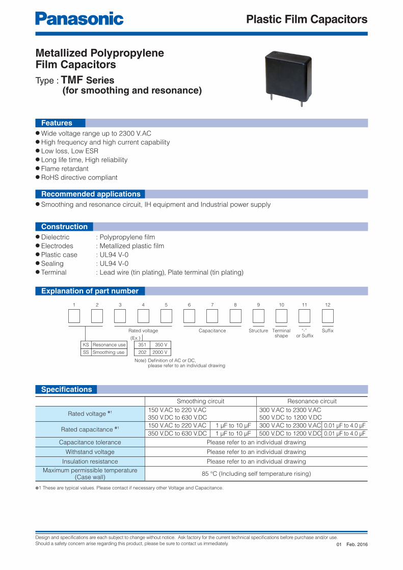
Design and specifications are each subject to change without notice. Ask factory for the current technical specifications before purchase and/or use.
Should a safety concern arise regarding this product, please be sure to contact us immediately.
Plastic Film Capacitors
1 2 3 4 5 6 7 8 9 11 12
Rated voltage
(Ex.)
Note) Definition of AC or DC, please refer to an individual drawing
Capacitance Structure Terminalshape
“-” or Suffix
Suffix
10
KS Resonance use
SS Smoothing use
351 350 V
202 2000 V
Metallized Polypropylene Film CapacitorsType : TMF Series (for smoothing and resonance)
Features● Wide voltage range up to 2300 V.AC● High frequency and high current capability● Low loss, Low ESR● Long life time, High reliability● Flame retardant● RoHS directive compliant
● Smoothing and resonance circuit, IH equipment and Industrial power supply
● Dielectric : Polypropylene fi lm● Electrodes : Metallized plastic fi lm● Plastic case : UL94 V-0● Sealing : UL94 V-0● Terminal : Lead wire (tin plating), Plate terminal (tin plating)
✽1 These are typical values. Please contact if necessary other Voltage and Capacitance.
Smoothing circuit Resonance circuit
Rated voltage ✽1 150 V.AC to 220 V.AC
350 V.DC to 630 V.DC
300 V.AC to 2300 V.AC
500 V.DC to 1200 V.DC
Rated capacitance ✽1 150 V.AC to 220 V.AC 1 μF to 10 μF 300 V.AC to 2300 V.AC 0.01 μF to 4.0 μF
350 V.DC to 630 V.DC 1 μF to 10 μF 500 V.DC to 1200 V.DC 0.01 μF to 4.0 μF
Capacitance tolerance Please refer to an individual drawing
Withstand voltage Please refer to an individual drawing
Insulation resistance Please refer to an individual drawing
Maximum permissible temperature (Case wall)
85 °C (Including self temperature rising)
Recommended applications
Construction
Explanation of part number
Specifi cations
Feb. 201601

Design and specifications are each subject to change without notice. Ask factory for the current technical specifications before purchase and/or use.
Should a safety concern arise regarding this product, please be sure to contact us immediately.
Plastic Film Capacitors
1 2 3 4 5 6 7 8 9 11 12
E C Q U A A F
Product code Dielectric &construction
SuffixRated voltage Capacitance Cap. Tol.
10
K ±10 %
M ±20 %
Code
Blank
A
Lead Form
Straight
Cut lead
● High humidity resistance (THB test : 85 °C/85 %/240 V.AC/1000 h (C < 1.0 μF)● High safety (safety function installed)● Compact● Flame-retardant plastic case and non-combustible resin● RoHS directive compliant
● Interference suppressors
✽ It is certifi ed as type ECQUA in the following approval.
Features
Applicable standard
Metallized Polypropylene Film CapacitorType : ECQUA [Class X2]
Category temperature range −40 °C to +110 °C
Rated voltage 275 V.AC
Rated capacitance 0.10 μF to 4.7 μF
Capacitance tolerance ±10 % (K), ±20 % (M)
Dissipation factor (tan d)C < 1.0 μF : tan d < 0.1 % ( 20 °C, 1 kHz )
C > 1.0 μF : tan d < 0.2 % ( 20 °C, 1 kHz )
Withstand voltageBetween terminals : 633 V.AC, 1183 V.DC, 60 s
Between terminals to enclosure : 2050 V.AC, 60 s
Insulation resistance (IR)
C < 0.33 μF : IR > 15000 MΩ (20 °C, 100 V.DC, 60 s)
C > 0.33 μF : IR > 5000 MΩ ∙ μF (20 °C, 100 V.DC, 60 s)
C < 0.47 μF : IR > 2000 MΩ (20 °C, 500 V.DC, 60 s)
Maximum AC voltage ✽ 310 V.AC
Approval Class Certifi cation organization
UL UL60384-14 Class X2UL
CSA CAN/CSA E60384-14 Class X2
Europe EN60384-14 Class X2VDE
International IEC60384-14 Class X2
✽ Use of this capacitor is limited to AC voltage (50 Hz or 60 Hz sine wave).✽ A faint corona discharge may occur inside of the capacitor element at rated voltage, however there is no influence on the reliability of the capacitor.
(Suitable for series to the mains usage - for more details, please contact your Panasonic contact person.)✽ Maximum AC voltage including line voltage fluctuation is 310 V.AC. 310 V.AC is not nominal continuous applied voltage, but only indicates maximum value including in the voltage ofthe power supply. Basic nominal voltage
is considered as 240 V.AC. This maximum AC voltae is specified in only ECQUA type, not specified in other types. Please refer to individual product specification, and contact us for further questions regarding design life.
✽ When applying this capacitor to European and American safety standards, please use type designation and rating such as ECQUA, 0.1 μF.✽ Approval number (File No.) of safety regulations are subject to revision without notice. Ask factory for a copy of the latest file No.
In accordance with UL/CSA and European safety regulation class X2
Equipped with a safety mechanism
Recommended applications
Explanation of part number
Specifi cations
Feb. 201803

Design and specifications are each subject to change without notice. Ask factory for the current technical specifications before purchase and/or use.
Should a safety concern arise regarding this product, please be sure to contact us immediately.
Plastic Film Capacitors
4.0±
0.5
Cut lead
(Suffix A)
ECQUA104275V ~ X2
(A) side (B) or (C) side
K
Marking Example
(C)
(A)
(B)
Solder-platedcopper-clad steel wire
P(Lead location limits from center)
0d±0.05
L±0.5 T±0.5
H±
0.5
F±0.4
20
min
.
Q+1.4–0.6
Note : Only ±10 % as cap. tol. be marked as “K”.
Note : Date code.
Unit : mm
● Capacitance tolerance : ±10 %(K), ±20 %(M)
Part No.Cap.(μF)
Dimensions (mm) Min. order Q'ty
L T H F fd P Q Straight Cut lead
ECQUAAF104◻( ) 0.10 17.5 5.0 12.0 15.0 0.6 0±0.8 1.3
10001000ECQUAAF154◻( ) 0.15 17.5 6.0 13.0 15.0 0.6 0±0.8 1.3
ECQUAAF224◻( ) 0.22 17.5 7.5 14.0 15.0 0.6 0±0.8 1.3
ECQUAAF334◻( ) 0.33 17.5 9.0 16.0 15.0 0.6 0±0.8 1.3 800
ECQUAAF474◻( ) 0.47 26.0 8.5 15.0 22.5 0.8 0±0.8 1.8 600
ECQUAAF684◻( ) 0.68 26.0 10.0 17.0 22.5 0.8 0±0.8 1.8 500 500
ECQUAAF105◻( ) 1.0 26.0 12.0 19.0 22.5 0.8 0±0.8 1.8 300 300
ECQUAAF155◻( ) 1.5 31.0 12.0 22.0 27.5 0.8 0±0.8 1.8 200 200
ECQUAAF225◻( ) 2.2 31.0 14.5 24.5 27.5 0.8 0±0.8 1.8
ECQUAAF335◻( ) 3.3 31.0 19.0 29.0 27.5 0.8 0±0.8 1.8 150 150
ECQUAAF475◻( ) 4.7 31.0 23.0 33.0 27.5 0.8 0±0.8 1.8 100 100
✽ ◻ : Capacitance tolerance code ( ) : Suffi x for lead form
Dimensions
Rating · Dimensions · Quantity
NEW
NEW
Feb. 201803

Design and specifications are each subject to change without notice. Ask factory for the current technical specifications before purchase and/or use.
Should a safety concern arise regarding this product, please be sure to contact us immediately.
Plastic Film Capacitors
1 2 3 4 5 6 7 8 9 11 12
E C Q U 2 A L
Product code Dielectric &construction
SuffixSuffixRated voltage Capacitance Cap. Tol.
10
K ±10 %
M ±20 %
Code
Blank
A
Lead Form
Straight
Cut lead
● Compact● Flame-retardant plastic case and non-combustible resin● RoHS directive compliant
● Interference suppressors
✽ It is certifi ed as type ECQUL in the following approval.
Features
Applicable standard
Metallized Polyester Film CapacitorType : ECQUL [Class X2] [Class Y2/X2]
Specifi cationsCategory temperature range −40 °C to +100 °C (85 °C max. on CSA C22.2 No.8 spec.)
Rated voltage 275 V.AC (250 V.AC on CSA C22.2 No.8 spec.)
Rated capacitance 0.0010 μF to 2.2 μF
Capacitance tolerance ±10 % (K), ±20 % (M)
Dissipation factor (tan d) tan d < 1.0 % (20 °C, 1 kHz)
Withstand voltageBetween terminals : 575 V.AC, 1768 V.DC, 60 s (0.0082 μF to 2.2 μF)Between terminals : 1500 V.AC, 2121 V.DC, 60 s (0.0010 μF to 0.0068 μF)Between terminals to enclosure : 2050 V.AC, 60 s
Insulation resistance (IR)C < 0.33 μF : IR > 15000 MΩ (20 °C, 100 V.DC, 60 s)C > 0.33 μF : IR > 5000 MΩ ∙ μF (20 °C, 100 V.DC, 60 s)IR > 2000 MΩ (20 °C, 500 V.DC, 60 s)
Approval Class Capacitance range Certifi cation organization
UL UL60384-14Class Y2/X2 (0.0010 μF to 0.0068 μF)
ULClass X2 (0.0082 μF to 2.2 μF)
CSA
CAN/CSA E60384-14Class Y2/X2 (0.0010 μF to 0.0068 μF)
CSAClass X2 (0.0082 μF to 2.2 μF)
CSA C22.2No.8-M1986
ElectromagneticInterference (EMI) Filters
(1.2 μF to 2.2 μF)
Europe EN60384-14Class Y2/X2 (0.0010 μF to 0.0068 μF)
VDEClass X2 (0.0082 μF to 2.2 μF)
International IEC60384-14Class Y2/X2 (0.0010 μF to 0.0068 μF)
Class X2 (0.0082 μF to 2.2 μF)
✽ Use of this capacitor is limited to AC voltage (50 Hz or 60 Hz sine wave).
✽ When applying this capacitor to European and American safety standards, please use type designation and rating such as ECQUL, 0.1 μF.✽ Approval number (File No.) of safety regulations are subject to revision without notice. Ask factory for a copy of the latest file No.✽ This capacitor is recognized for European standards by VDE only. But, there are no problems using this capacitor in a device which will get approvals
from certification bodies in Europe, SEMKO, DEMKO, NEMKO, FIMKO and SEV etc.
In accordance with UL/CSA and European safety
regulation class X2 or class Y2/X2
Recommended applications
Explanation of part number
Sep. 201703

Design and specifications are each subject to change without notice. Ask factory for the current technical specifications before purchase and/or use.
Should a safety concern arise regarding this product, please be sure to contact us immediately.
Plastic Film Capacitors
Marking example
✽ > 1.2 μF±1.04.
0±0.
5
Cut lead
(Suffix A)
(A)
(B)
Solder-plated copper-clad steel wire
0d±0.05
L±0.5✽T±0.5✽
H±
0.5
✽
F±0.4
20
min
.
Q+1.4–0.6
0.0010 μF to 0.0068 μF
1
0.0082 μF to 1.0 μF
2
1.2 μF to 2.2 μF
3
.001 μF KE C Q U L2 7 5 V ~X2/Y2
.0082 μF K
1.5 μF K
E C Q U L2 7 5 V ~X2
E C Q U L8X250 V~ 2 7 5 V ~
X2
(A) sideSTYLE (B) side
Note : Only ±10 % as cap. tol. be marked as “K”.
Note : Date code.
P(Lead location limits from center)
Unit : mm
● Capacitance tolerance : ±10 %(K), ±20 %(M)
✽ ◻ : Capacitance tolerance code ( ) : Suffi x for lead form
Dimensions
Rating · Dimensions · Quantity
Part No.Capacitance
(μF)Dimensions (mm) Min. order Q'ty
L T H F fd P Q Straight Cut leadECQU2A102◻L( ) 0.0010 15.0 5.0 11.5 12.5 0.6 0±0.50 1.3
500 500
ECQU2A122◻L( ) 0.0012 15.0 5.0 11.5 12.5 0.6 0±0.50 1.3ECQU2A152◻L( ) 0.0015 15.0 5.0 11.5 12.5 0.6 0±0.50 1.3ECQU2A182◻L( ) 0.0018 15.0 5.0 11.5 12.5 0.6 0±0.50 1.3ECQU2A222◻L( ) 0.0022 15.0 5.0 11.5 12.5 0.6 0±0.50 1.3ECQU2A272◻L( ) 0.0027 15.0 5.0 11.5 12.5 0.6 0±0.50 1.3ECQU2A332◻L( ) 0.0033 15.0 5.0 11.5 12.5 0.6 0±0.50 1.3ECQU2A392◻L( ) 0.0039 15.0 5.0 11.5 12.5 0.6 0±0.50 1.3ECQU2A472◻L( ) 0.0047 15.0 5.0 11.5 12.5 0.6 0±0.50 1.3ECQU2A562◻L( ) 0.0056 15.0 5.0 11.5 12.5 0.6 0±0.50 1.3ECQU2A682◻L( ) 0.0068 15.0 5.0 11.5 12.5 0.6 0±0.50 1.3ECQU2A822◻L( ) 0.0082 15.0 5.0 11.5 12.5 0.6 0±0.50 1.3ECQU2A103◻L( ) 0.010 15.0 5.0 11.5 12.5 0.6 0±0.50 1.3ECQU2A123◻L( ) 0.012 15.0 5.0 11.5 12.5 0.6 0±0.50 1.3ECQU2A153◻L( ) 0.015 15.0 5.0 11.5 12.5 0.6 0±0.50 1.3ECQU2A183◻L( ) 0.018 15.0 5.0 11.5 12.5 0.6 0±0.50 1.3ECQU2A223◻L( ) 0.022 15.0 5.0 11.5 12.5 0.6 0±0.50 1.3ECQU2A273◻L( ) 0.027 15.0 5.0 11.5 12.5 0.6 0±0.50 1.3ECQU2A333◻L( ) 0.033 15.0 6.0 13.0 12.5 0.6 0±0.50 1.3ECQU2A393◻L( ) 0.039 15.0 6.0 13.0 12.5 0.6 0±0.50 1.3ECQU2A473◻L( ) 0.047 15.0 6.0 13.0 12.5 0.6 0±0.50 1.3ECQU2A563◻L( ) 0.056 17.5 4.5 11.5 15.0 0.6 0±0.50 1.3ECQU2A683◻L( ) 0.068 17.5 4.5 11.5 15.0 0.6 0±0.50 1.3ECQU2A823◻L( ) 0.082 17.5 5.5 12.0 15.0 0.6 0±0.50 1.3ECQU2A104◻L( ) 0.10 17.5 5.5 12.0 15.0 0.6 0±0.50 1.3ECQU2A124◻L( ) 0.12 17.5 6.5 14.5 15.0 0.6 0±0.50 1.3ECQU2A154◻L( ) 0.15 17.5 6.5 14.5 15.0 0.6 0±0.50 1.3ECQU2A184◻L( ) 0.18 17.5 8.0 16.0 15.0 0.6 0±0.50 1.3ECQU2A224◻L( ) 0.22 17.5 8.0 16.0 15.0 0.6 0±0.50 1.3ECQU2A274◻L( ) 0.27 17.5 9.5 17.5 15.0 0.8 0±0.50 1.3ECQU2A334◻L( ) 0.33 17.5 9.5 17.5 15.0 0.8 0±0.50 1.3ECQU2A394◻L( ) 0.39 25.5 8.5 17.5 22.5 0.8 0±0.75 1.5ECQU2A474◻L( ) 0.47 25.5 8.5 17.5 22.5 0.8 0±0.75 1.5ECQU2A564◻L( ) 0.56 25.5 10.5 19.5 22.5 0.8 0±0.75 1.5ECQU2A684◻L( ) 0.68 25.5 10.5 19.5 22.5 0.8 0±0.75 1.5ECQU2A824◻L( ) 0.82 25.5 12.0 22.0 22.5 0.8 0±0.75 1.5
300 400ECQU2A105◻L( ) 1.0 25.5 12.0 22.0 22.5 0.8 0±0.75 1.5ECQU2A125◻L( ) 1.2 30.5 16.5 26.0 27.5 0.8 0±0.75 1.5
200 200ECQU2A155◻L( ) 1.5 30.5 16.5 26.0 27.5 0.8 0±0.75 1.5ECQU2A185◻L( ) 1.8 30.5 19.0 29.5 27.5 0.8 0±0.75 1.5
150 150ECQU2A225◻L( ) 2.2 30.5 19.0 29.5 27.5 0.8 0±0.75 1.5
Sep. 201703

Design and specifications are each subject to change without notice. Ask factory for the current technical specifications before purchase and/or use.
Should a safety concern arise regarding this product, please be sure to contact us immediately.
Plastic Film Capacitors
1 2 3 4 5 6 7 8 9 11 12
E C Q U 3 A
Product code Dielectric &construction
SuffixSuffixRated voltage Capacitance Cap. Tol.
10
M ±20 %
M G
Code
Blank
A
Lead Form
Straight
Cut lead
● Equipped with a safety mechanism● Flame-retardant plastic case and non combustible resin● RoHS directive compliant
● Interference suppressors
✽ It is certifi ed as type ECQUG in the following approval.
Features
Metallized Polyester Film CapacitorType : ECQUG [Class X1]
Category temperature range −40 °C to +100 °C
Rated voltage 300 V.AC
Rated capacitance 0.010 μF to 1.0 μF (E6)
Capacitance tolerance ±20 % (M)
Dissipation factor (tan d) tan d < 1.0 % (20 °C, 1 kHz )
Withstand voltageBetween terminals : 575 V.AC, 1768 V.DC, 60 s
Between terminals to enclosure : 2100 V.AC, 60 s
Insulation resistance (IR)
C < 0.33 μF : IR > 15000 MΩ (20 °C, 100 V.DC, 60 s)
C > 0.33 μF : IR > 5000 MΩ ∙ μF (20 °C, 100 V.DC, 60 s)
IR > 2000 MΩ (20 °C, 500 V.DC, 60 s)
Approval Class Certifi cation organization
UL UL60384-14 Class X1 UL
CSA CAN/CSA E60384-14 Class X1 CSA
Europe EN60384-14 Class X1VDE
International IEC60384-14 Class X1
✽ Use of this capacitor is limited to AC voltage (50 Hz or 60 Hz sine wave).
✽ When applying this capacitor to European and American safety standards, please use type designation and rating such as ECQUG, 0.1 μF.
✽ Approval number (File No.) of safety regulations are subject to revision without notice. Ask factory for a copy of the latest file No..
✽ European standards marking are ENEC (VDE). But, there are no problem using this capacitor in a device which will get approvals from certification bodies
in Europe, NEMKO, FIMKO, SEMKO, DEMKO, and SEV etc.
In accordance with UL/CSA
and European safety regulation class X1
Recommended applications
Explanation of part number
Applicable standard
Specifi cations
Sep. 201704
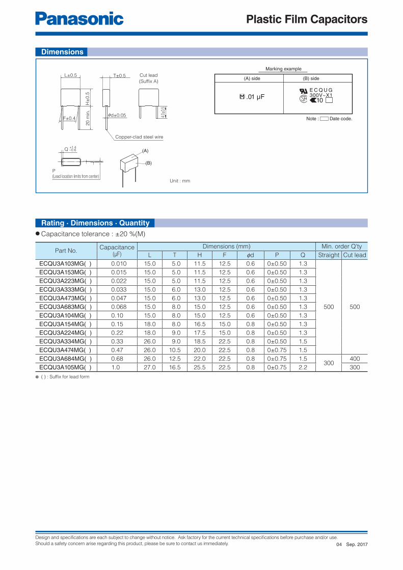
Design and specifications are each subject to change without notice. Ask factory for the current technical specifications before purchase and/or use.
Should a safety concern arise regarding this product, please be sure to contact us immediately.
Plastic Film Capacitors
4.0±
0.5
Cut lead
(Suffix A)
(A)
(B)
Copper-clad steel wire
0d±0.05
L±0.5 T±0.5
H±
0.5
F±0.4
20
min
.
Q+1.4–0.6
P(Lead location limits from center)
(A) side (B) side
Marking example
.01 μFE C Q U G300V~X1
10
Note : Date code.
Unit : mm
● Capacitance tolerance : ±20 %(M)
Part No.Capacitance
(μF)
Dimensions (mm) Min. order Q'ty
L T H F fd P Q Straight Cut lead
ECQU3A103MG( ) 0.010 15.0 5.0 11.5 12.5 0.6 0±0.50 1.3
500 500
ECQU3A153MG( ) 0.015 15.0 5.0 11.5 12.5 0.6 0±0.50 1.3
ECQU3A223MG( ) 0.022 15.0 5.0 11.5 12.5 0.6 0±0.50 1.3
ECQU3A333MG( ) 0.033 15.0 6.0 13.0 12.5 0.6 0±0.50 1.3
ECQU3A473MG( ) 0.047 15.0 6.0 13.0 12.5 0.6 0±0.50 1.3
ECQU3A683MG( ) 0.068 15.0 8.0 15.0 12.5 0.6 0±0.50 1.3
ECQU3A104MG( ) 0.10 15.0 8.0 15.0 12.5 0.6 0±0.50 1.3
ECQU3A154MG( ) 0.15 18.0 8.0 16.5 15.0 0.8 0±0.50 1.3
ECQU3A224MG( ) 0.22 18.0 9.0 17.5 15.0 0.8 0±0.50 1.3
ECQU3A334MG( ) 0.33 26.0 9.0 18.5 22.5 0.8 0±0.50 1.5
ECQU3A474MG( ) 0.47 26.0 10.5 20.0 22.5 0.8 0±0.75 1.5
ECQU3A684MG( ) 0.68 26.0 12.5 22.0 22.5 0.8 0±0.75 1.5300
400
ECQU3A105MG( ) 1.0 27.0 16.5 25.5 22.5 0.8 0±0.75 2.2 300
✽ ( ) : Suffi x for lead form
Dimensions
Rating · Dimensions · Quantity
Sep. 201704

Design and specifications are each subject to change without notice. Ask factory for the current technical specifications before purchase and/or use.
Should a safety concern arise regarding this product, please be sure to contact us immediately.
Plastic Film Capacitors
1 2 3 4 5 6 7 8 9 11 12
D S
Rated voltage Capacitance Externals structure Suffix
10
1 2 3 4 5 6 7 8 9 11 12
E Z W
Product code Dielectric &construction
SuffixRated voltage Capacitance SuffixTerminalshape
10
Film Capacitor for AC MotorType : AMF Series
Features● High safety (Safety function installed)● High reliability● Small size, lightness, and low loss● RoHS directive compliant
● Motor and compressor (for running)
● Internal electrode : Metallized plastic fi lm (Safety function installed)● Plastic case : UL94 V-0● Sealing : UL94 V-0● Terminal : Faston terminal (tin plating)
✽1 The range of approval is different depending on each approval.✽2 These are typical values.
Applicable standard ✽1 JIS UL
Safety class Safety function installed P2 (CMJ approval), 10000 AFC (UL)
Rated voltage (50/60 Hz) ✽2 180 V.AC to 440 V.AC
Rated capacitance ✽2 10 μF to 40 μF
Capacitance tolerance −5 %/+10 % (Refer to the individual drawing)
Withstandvoltage
Between terminals Rated voltage × 1.75, 60 s
Between terminalsto enclosure
(min. 2000 V.AC)
Rated voltage × 2.0+1000 (V.AC), 60 s
Maximum permissible temperature(Case wall)
70 °C (Including self temperature rising)
JapanJIS C 4908 Capacitors for electrical apparatus
CMJ registration parts. Registration No.1475- C9902-026(JET)
UL/cUL UL810/CSA C22.2 No. 190 FILE No. E76560
Recommended applications
Construction
Explanation of part number
Applicable standard
Specifi cations
Feb. 201601
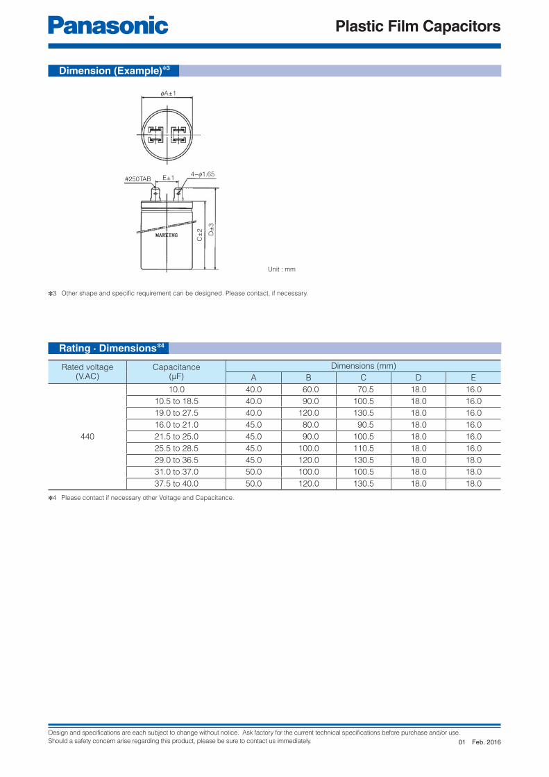
Design and specifications are each subject to change without notice. Ask factory for the current technical specifications before purchase and/or use.
Should a safety concern arise regarding this product, please be sure to contact us immediately.
Plastic Film Capacitors
✽3 Other shape and specific requirement can be designed. Please contact, if necessary.
✽4 Please contact if necessary other Voltage and Capacitance.
Unit : mm
Rated voltage(V.AC)
Capacitance(μF)
Dimensions (mm)
A B C D E
440
10.0 40.0 60.0 70.5 18.0 16.0
10.5 to 18.5 40.0 90.0 100.5 18.0 16.0
19.0 to 27.5 40.0 120.0 130.5 18.0 16.0
16.0 to 21.0 45.0 80.0 90.5 18.0 16.0
21.5 to 25.0 45.0 90.0 100.5 18.0 16.0
25.5 to 28.5 45.0 100.0 110.5 18.0 16.0
29.0 to 36.5 45.0 120.0 130.5 18.0 18.0
31.0 to 37.0 50.0 100.0 100.5 18.0 18.0
37.5 to 40.0 50.0 120.0 130.5 18.0 18.0
fA±1
4−f1.65#250TAB E±1
C±
2
D±
3
Dimension (Example)✽3
Rating · Dimensions✽4
Feb. 201601

Design and specifications are each subject to change without notice. Ask factory for the current technical specifications before purchase and/or use.
Should a safety concern arise regarding this product, please be sure to contact us immediately.
Plastic Film Capacitors
1 2 3 4 5 6 7 8 9 11 12
D S
Rated voltage Capacitance Externals structure Suffix
10
1 2 3 4 5 6 7 8 9 11 12
E Z W
Product code Dielectric &construction
SuffixRated voltage Capacitance SuffixTerminalshape
10
Film Capacitor for AC MotorType : DMF Series
Features● High safety (with built-in safety device)● High reliability, Safety standard approval● Small size, lightness, and low loss● RoHS directive compliant
● Motor and compressor (for running)
● Internal electrode : Metallized plastic fi lm● Exterior material : Metal case (oil sealing up type)● Terminal : Faston terminal (tin plating)
✽1 The range of approval is different depending on each approval.✽2 These are typical values.
Applicable standard ✽1 JIS UL EN GB
Safety classWith built-in safety device
P1(CMJ approval) 10000 AFC (UL)S2
Rated voltage (50/60 Hz) ✽2 180 V.AC to 450 V.AC EN GB : 440 V.AC, 450 V.AC
Rated capacitance ✽2 10 μF to 60 μF
Capacitance tolerance −5 %/+10 %, ±5 % (Refer to the individual drawing)
Withstandvoltage
Between terminals Rated voltage × 1.75, 60 s Rated voltage × 2.0, 60 s
Between terminalsto enclosure
(min. 2000 V.AC)
Rated voltage × 2.0+1000 (V.AC), 60 s
Maximum permissible temperature(Case wall)
70 °C (Including self temperature rising)
JapanJIS C 4908 Capacitors for electrical apparatus
CMJ registration parts. Registration No.1475- C9902-026(JET)
UL/cUL UL810/CSA C22.2 No. 190 FILE No. E76560
Europe EN60252-1 AC motor Capacitors TUV
China GB/T 3667.1 AC motor Capacitors CQC
Specifi cations
Applicable standard
Recommended applications
Construction
Explanation of part number
Sep. 201702

Design and specifications are each subject to change without notice. Ask factory for the current technical specifications before purchase and/or use.
Should a safety concern arise regarding this product, please be sure to contact us immediately.
Plastic Film Capacitors
Current Derating
✽3 Other shape and specific requirement can be designed. Please contact, if necessary. Three tabs and as many as four tabs are also possible though standards of the number of terminal tabs are two tabs.
✽4 Please contact if necessary other Voltage and Capacitance.
Dimension (Example)✽3
Rating · Dimensions✽4
Unit : mm
Rated voltage
(V.AC)
Capacitance
(μF)
Dimensions (mm)
A B C D E
370 to 440
5.0 to 10.0 43.0 41.0 70.0 83.0 16.0
11.0 to 15.0 43.0 41.0 80.0 93.0 16.0
16.0 to 20.0 43.0 41.0 90.0 103.0 16.0
21.0 to 25.0 43.0 41.0 100.0 113.0 16.0
26.0 to 30.0 43.0 41.0 110.0 123.0 16.0
31.0 to 35.0 43.0 41.0 130.0 143.0 16.0
36.0 to 40.0 48.0 45.0 110.0 123.0 18.0
41.0 to 50.0 48.0 45.0 130.0 143.0 18.0
51.0 to 55.0 53.0 50.5 110.0 123.0 18.0
56.0 to 60.0 63.0 60.5 90.0 103.0 20.0
61.0 to 65.0 63.0 60.5 100.0 113.0 20.0
Rated voltage
(V.AC)
Capacitance
(μF)
Dimensions (mm)
A B C D E
450
5.0 to 10.0 43.0 41.0 70.0 83.0 16.0
11.0 to 15.0 43.0 41.0 90.0 103.0 16.0
16.0 to 20.0 43.0 41.0 110.0 123.0 16.0
21.0 to 25.0 48.0 45.0 100.0 113.0 18.0
26.0 to 30.0 48.0 45.0 110.0 123.0 18.0
31.0 to 35.0 53.0 50.5 100.0 113.0 18.0
36.0 to 40.0 53.0 50.5 110.0 123.0 18.0
41.0 to 50.0 63.0 60.5 100.0 113.0 20.0
51.0 to 55.0 63.0 60.5 110.0 123.0 20.0
56.0 to 60.0 63.0 60.5 130.0 143.0 20.0
Sep. 201702

Design and specifications are each subject to change without notice. Ask factory for the current technical specifications before purchase and/or use.
Should a safety concern arise regarding this product, please be sure to contact us immediately.
Plastic Film Capacitors
1 2 3 4 5 6 7 8 9 11 12
D S
Rated voltage Capacitance Externals structure Suffix
10
1 2 3 4 5 6 7 8 9 11 12
E Z P
Product code Dielectric &construction
SuffixRated voltage Capacitance SuffixTerminalshape
10
Film Capacitor for AC MotorType : PMF Series
Features● High safety (safety function installed)● High reliability, safety standard approval● Small size, lightness, and low loss● RoHS directive compliant
● Motor and small compressor (for running)
● Internal electrode : Metallized plastic fi lm (safety function installed)● Plastic case : UL94 V-0● Sealing : UL94 V-0● Terminal : Faston terminal (tin plating), Lead wire (tin plating), Insulated wire
✽1 The range of approval is different depending on each approval.✽2 These are typical values.
Applicable standard ✽1 JIS UL EN GB
Safety classWith built-in safety function
P2 (CMJ approval) 10000 AFC (UL)S3
Rated voltage (50/60 Hz) ✽2 150 V.AC to 500 V.AC(For UL Approved P/N : up to 480 V.AC)
EN/TUV : 450 V.ACGB : 250 V.AC, 450 V.AC
Rated capacitance ✽2 0.5 μF to 65 μF
Capacitance tolerance −5 %/+10 %, ±5 % (Refer to the individual drawing)
Withstandvoltage
Between terminals Rated voltage ×1.75, 60 s Rated voltage ×2.0, 60 s
Between terminalsto enclosure
(min. 2000 V)
Rated voltage × 2.0+1000 (V), 60 s
Maximum permissible temperature (Case wall) 70 °C (Including self temperature rising)
JapanJIS C 4908 Capacitors for electrical apparatus
CMJ registration parts. Registration No.1475- C9902-026(JET)
UL/cUL
CSA
UL810 FILE No. E76560
CSA C22.2 No. 190
Europe EN60252-1 AC motor Capacitors TUV
China GB/T 3667.1 AC motor Capacitors CQC
Recommended applications
Explanation of part number
Construction
Applicable standard
Specifi cations
Sep. 201702

Design and specifications are each subject to change without notice. Ask factory for the current technical specifications before purchase and/or use.
Should a safety concern arise regarding this product, please be sure to contact us immediately.
Plastic Film Capacitors
✽3 Other shape and specific requirement can be designed. Please contact, if necessary.
Dimension (Example)✽3
Unit : mm
Unit : mm
Unit : mm
● Q series (Mounting type) ✽ Non Mounting type is available. (P series).
● T series (Printed circuit board (PCB))
● Terminal shape (Standard)
#187 tabs Lead wire type
A±0.5
C±
0.5
10 m
ax.
E±
1.0
F±
1.0
C±
1.0
F±
0.5
4.0±
1.0
4.0±
1.0
G
f4.3±0.3
18
B±0.5
P±1.0
A±1.0
4.0 min. 4.0 min.
6.2±0.5
D±0.5H±0.5
Lap±2.5 max.
1.5
f0.8±0.1
10 m
ax.
f1.4
f0.8
Sep. 201702

Design and specifications are each subject to change without notice. Ask factory for the current technical specifications before purchase and/or use.
Should a safety concern arise regarding this product, please be sure to contact us immediately.
Plastic Film Capacitors
✽4 Please contact if necessary other Voltage and Capacitance.
Rating · Dimensions✽4
Rated voltage
(V.AC)
Capacitance
(μF)
Dimensions (mm) Case
seriesA B C D E F G H
250
3.0 to 4.5 39.5 38.5 16.2 14.8 27.0 27.0
4.011.5
Q
5.0 to 6.0 39.5 38.2 18.3 16.8 29.0 29.0
6.5 to 9.5 39.5 38.2 22.0 20.8 32.5 32.5
10.0 to 16.0 49.7 48.3 24.0 22.5 34.5 34.5
16.5 to 20.0 50.0 48.5 26.7 25.3 37.5 38.0
20.5 to 25.0 50.0 48.5 30.5 28.8 41.0 41.5
25.5 to 34.5 50.0 48.5 34.0 32.6 45.0 45.0 6.0
450
1.0 to 1.4 39.5 38.5 16.2 14.8 27.0 27.0
4.011.5
1.5 to 1.8 39.5 38.2 18.3 16.8 29.0 29.0
1.9 to 2.5 39.5 38.2 22.0 20.8 32.5 32.5
3.0 to 5.0 49.7 48.3 24.0 22.5 34.5 34.5
5.5 to 6.5 50.0 48.5 26.7 25.3 37.5 38.0
7.0 to 8.0 50.0 48.5 30.5 28.8 41.0 41.5
8.5 to 10.5 50.0 48.5 34.0 32.6 45.0 45.0 6.0
Rated voltage
(V.AC)
Capacitance
(μF)
Dimensions (mm) Case
seriesA C F P
250
3.0 to 4.0 38.5 14.0 25.5 36.0
T
4.5 to 6.5 38.5 15.5 29.0 36.0
7.0 to 8.0 38.5 20.5 29.0 36.0
8.5 to 11.0 38.5 25.0 34.0 36.0
11.5 to 18.5 48.5 22.0 36.0 46.0
450
1.0 to 1.3 38.5 14.0 25.5 36.0
1.4 to 2.0 38.5 15.5 29.0 36.0
2.1 to 2.5 38.5 20.5 29.0 36.0
3.0 to 3.5 38.5 25.0 34.0 36.0
4.0 to 5.5 48.5 22.0 36.0 46.0
● Q series (Mounting type)
● T series (Printed circuit board (PCB))
Sep. 201702

Design and specifications are each subject to change without notice. Ask factory for the current technical specifications before purchase and/or use.
Should a safety concern arise regarding this product, please be sure to contact us immediately.
Plastic Film Capacitors
1 2 3 4 5 6 7 8 9 11 12
D S
Rated voltage Capacitance Externals structure Suffix
10
1 2 3 4 5 6 7 8 9 11 12
E Z S
Product code Dielectric &construction
SuffixRated voltage Capacitance SuffixTerminalshape
10
Film Capacitor for AC MotorType : SMF Series
Features● High safety (safety function installed)● High reliability, safety standard approval● Small size, lightness, and low loss● RoHS directive compliant
● Motor and small compressor (for running)
● Internal electrode : Metallized plastic fi lm (safety function installed)● Plastic case : UL94 V-0● Sealing : UL94 V-0● Terminal : Faston terminal (tin plating), Lead wire (tin plating), Insulated wire
✽1 The range of approval is different depending on each approval.✽2 These are typical values.
Applicable standard ✽1 JIS UL EN GB
Safety classWith built-in safety function
P2 (CMJ approval) 10000 AFC (UL) S0
Rated voltage (50/60 Hz) ✽2 370 V.AC to 450 V.AC 400 V.AC, 450 V.AC
Rated capacitance ✽2 1.5 μF to 9 μF
Capacitance tolerance −5 %/+10 %, ±5 % (Refer to the individual drawing)
Withstandvoltage
Between terminals Rated voltage ×1.75, 60 s Rated voltage ×2.0, 60 s
Between terminalsto enclosure
(min. 2000 V)
Rated voltage × 2.0+1000 (V), 60 s
Maximum permissible temperature(Case wall)
70 °C (Including self temperature rising)
JapanJIS C 4908 Capacitors for electrical apparatus
CMJ registration parts. Registration No.1475- C9902-026(JET)
UL/cUL UL810 FILE No. E76560
Europe EN60252-1 AC motor Capacitors VDE
China GB/T 3667.1 AC motor Capacitors CQC
Recommended applications
Construction
Explanation of part number
Applicable standard
Specifi cations
Sep. 201702
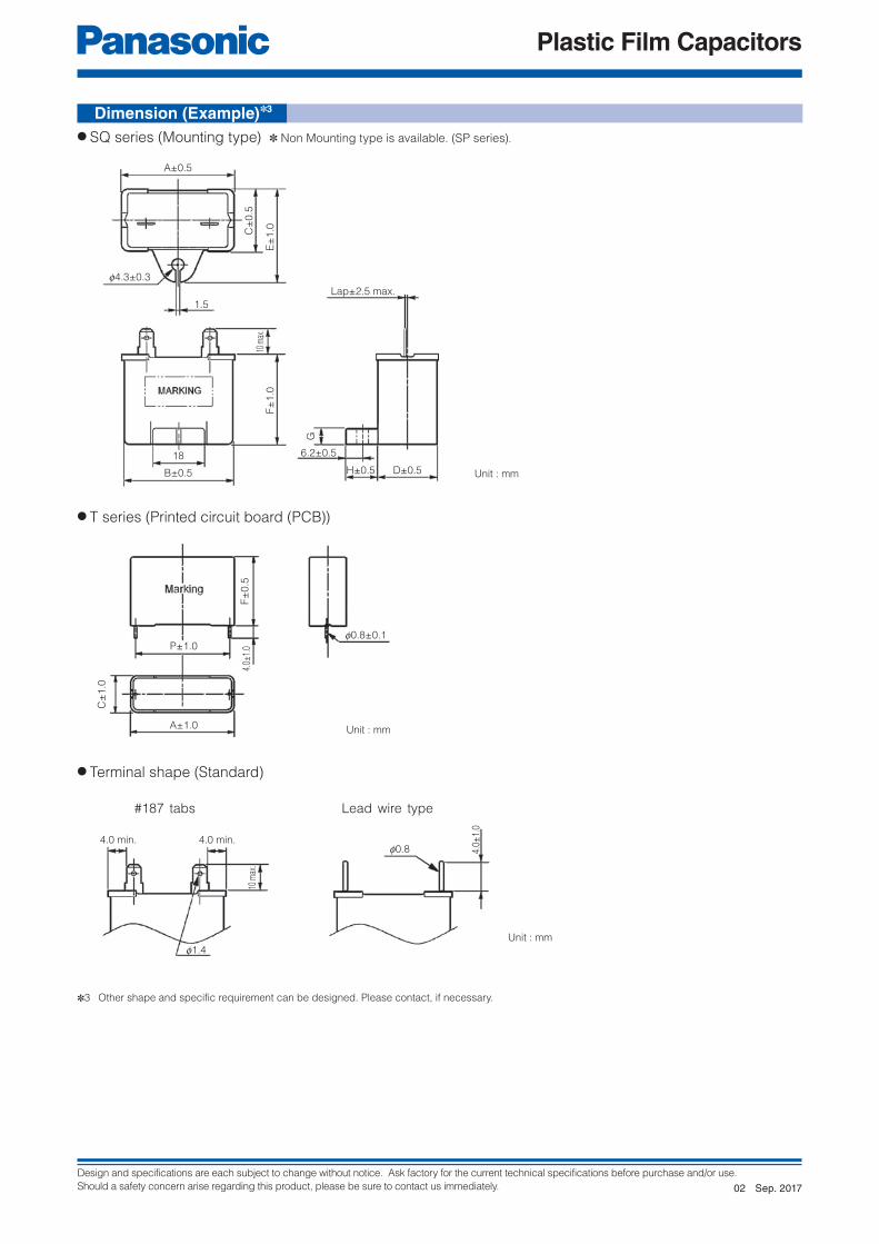
Design and specifications are each subject to change without notice. Ask factory for the current technical specifications before purchase and/or use.
Should a safety concern arise regarding this product, please be sure to contact us immediately.
Plastic Film Capacitors
✽3 Other shape and specific requirement can be designed. Please contact, if necessary.
Unit : mm
Unit : mm
Unit : mm
● SQ series (Mounting type) ✽ Non Mounting type is available. (SP series).
● T series (Printed circuit board (PCB))
● Terminal shape (Standard)
#187 tabs Lead wire type
A±0.5
C±
0.5
10 m
ax.
E±
1.0
F±
1.0
C±
1.0
F±
0.5
4.0±
1.0
4.0±
1.0
G
f4.3±0.3
18
B±0.5
P±1.0
A±1.0
4.0 min. 4.0 min.
6.2±0.5
D±0.5H±0.5
Lap±2.5 max.
1.5
f0.8±0.1
10 m
ax.
f1.4
f0.8
Dimension (Example)✽3
Sep. 201702

Design and specifications are each subject to change without notice. Ask factory for the current technical specifications before purchase and/or use.
Should a safety concern arise regarding this product, please be sure to contact us immediately.
Plastic Film Capacitors
✽4 Please contact if necessary other Voltage and Capacitance.
Rated voltage
(V.AC)
Capacitance
(μF)
Dimensions (mm) Case
seriesA B C D E F G H
400
1.5 to 3.0 39.5 38.0 16.0 14.5 26.5 30.5
4.0 11.0
SQ
3.5 39.5 38.0 17.5 16.0 28.0 30.5
4.0 to 5.0 39.5 38.0 22.0 20.5 32.5 30.5
5.5 to 6.5 39.5 38.0 26.7 25.2 37.0 32.0
7.0 to 8.0 39.5 38.0 26.7 25.2 37.0 37.0
8.5 to 9.0 39.5 38.0 26.7 25.2 37.0 41.0
450
1.5 to 2.5 39.5 38.0 16.0 14.5 26.5 30.5
4.0 11.0
3.0 39.5 38.0 17.5 16.0 28.0 30.5
3.5 to 4.0 39.5 38.0 22.0 20.5 32.5 30.5
4.5 to 5.5 39.5 38.0 26.7 25.2 37.0 32.0
6.0 to 6.5 39.5 38.0 26.7 25.2 37.0 37.0
7.0 to 7.5 39.5 38.0 26.7 25.2 37.0 41.0
Rated voltage
(V.AC)
Capacitance
(μF)
Dimensions (mm) Case
seriesA C F P
400
1.5 to 2.5 38.5 14.0 25.5 36.0
T
3.0 to 3.5 38.5 15.5 29.0 36.0
4.0 to 5.0 38.5 20.5 29.0 36.0
5.5 to 7.5 38.5 25.0 34.0 36.0
450
1.5 to 2.0 38.5 14.0 25.5 36.0
2.5 to 3.0 38.5 15.5 29.0 36.0
3.5 to 4.0 38.5 20.5 29.0 36.0
4.5 to 6.5 38.5 25.0 34.0 36.0
● SQ series (Installation leg type)
● T series (Printed circuit board (PCB))
Rating · Dimensions✽4
Sep. 201702

Design and specifications are each subject to change without notice. Ask factory for the current technical specifications before purchase and/or use.
Should a safety concern arise regarding this product, please be sure to contact us immediately.
Plastic Film Capacitors
1 2 3 4 5 6 7 8 9 11 12
E C Q E 2 4 7 4
Product code Dielectric &construction
SuffixSuffixRated voltage Capacitance Suffix
10
Suffix
Connector : Type 090, 090II, 187 etc.
L=80 mm, 90 mm, 100 mm, 110 mm, 120 mm etc.
L±10
Mark
ing
Connecting diagram
Ma
rkin
g
Connecting diagram
● Excellent water-proof and corrosion-proof construction properties.● Guaranteed operation temperture of 130 °C max● Available with wide variety of terminals, including blacket and lead wire● RoHS directive compliant
● Noise suppression for automobile
Features
Metallized Polyester Film Capacitor for Noise suppression of AutomobileType : ECQE
Category temperature range
(Including temperature-rise on unit surface)
−40 °C to +130 °C
(Except cord, connector, tube and tape)
Rated voltage ✽ 250 V.DC (Derating of rated voltage by 1.11 %/°C at more than 85 °C)
Rated capacitance ✽ 0.47 μF, 2.2 μF, 4.7 μF
Capacitance tolerance ±20 % (M)
Dissipation factor (tan d) tan d < 1.0 % (20 °C, 1 kHz )
Withstand voltage 250 V.DC×150 % for 60 s
Insulation resistance (IR) IR > 3000 MΩ ∙ μF (20 °C, 100 V.DC, 60 s)
Non-inductive construction using metallized polyester
fi lm with fl ame retardant epoxy resin
Dimensions (Example)
✽ Other voltage ratings, capacitance values and special dimensions are available upon request. Please consult engineering section.
Recommended applications
Explanation of part number
Applicable standard
Sep. 201702

Design and specifications are each subject to change without notice. Ask factory for the current technical specifications before purchase and/or use.
Should a safety concern arise regarding this product, please be sure to contact us immediately.
Plastic Film Capacitors
1 2 3 4 5 6 7 8 9 10 11 12
E Z T V K C YT P H1 A
DC-Link Film CapacitorType : TYPE1
Features
Recommended applications
Construction
● High safety, Self-healing and Self-protecting function built in.● No catastrophic failure upon natural end of life due to inbuilt fuse function.● Open circuit failure mode by fuse function patterned electrode● Can replace Electrolytic Capacitor● Low ESR, High Ripple Current capability● Low ESL● RoHS directive compliant
● Any automotive and/or other application requiring DC Linkage
✽ Verify the usage and fi tting environments, and make sure to observe the rated performance specifi ed in the
corresponding specifi cations.
● Dielectric : Polypropylene● Electrode : Metallized dielectric with Segment pattern● Plastic Case : PPS. equivalent to UL94 V-0● Sealing : Epoxy Resin equivalent to UL94 HB● Terminal : Copper with Tin plating
Note:1) Voltage includes ripple voltage2) Derate the current when the maximum surface temperature exceeds 95 degC, as shown in Fig. 1.
Operating temperature
on the surface of the case
– 40 °C to +105 °C
including self heat generation
Capacitance 581 μF +10 % at 1 kHz, 25 ºC
Rated voltage 450 V.DC
Maximum voltage 600 V.DC for 60 sec in life time
Rated ripple current Continuous 80 Arms at 10 kHz
Current derating Refer Fig.1
ESR 0.8 mΩ or less at 10KHz
ESL 20 nH or less at 1MHz
Insulation Resistance
between Terminals and Case1 GΩ or moreMeasure after applying 500 V.DC for 2 seconds.
Dimensions L × W × H (Typical data) 164 × 115 × 43.1 mm : Excluding terminals
Weight (Typical data) 980 g
−5 %
Explanation of part number
Specifi cations
Sep. 201702

Design and specifications are each subject to change without notice. Ask factory for the current technical specifications before purchase and/or use.
Should a safety concern arise regarding this product, please be sure to contact us immediately.
Plastic Film Capacitors
−40 60
100
90
80
70
60
50
40
30
20
10
065 70 75 80 85 90 100 105 11095
95 °C
Rip
ple
cu
rre
nt (A
rms @
10
k H
z)
Temperature on the surface of the capacitor housing (°C)
Fig.1 Current derating curve
43.1
±1
164±1
136±1
N P
8±
0.3
17±
0.4
1
22.5
34.5
±0.7
70±
0.492.5
(7.5)
(6.5)
149±0.4
2-12
6
18±
1
(22)63.5±0.4
85.5±0.4
2-f6.5 +0.30
(34.5)80
STAMPING AREA
(51.5
)33
STA
MP
ING
AR
EA
(20)
(40)
HATCHED AREA : LABEL
4-f6.9 +0.30
Unit : mm
Dimensions
Current Derating
Sep. 201702

Design and specifications are each subject to change without notice. Ask factory for the current technical specifications before purchase and/or use.
Should a safety concern arise regarding this product, please be sure to contact us immediately.
Plastic Film Capacitors
ES
R (
mΩ
)
10
1.0
0.0
0.2
0.4
0.6
0.8
15Frequency (kHz)
ESR
20 25
−40 −20
10
−10
−5
0
5
20 40Temperature (°C)
ΔC
/C (
%)
at 1 k
Hz
ΔC/C
60 80 1000
10
0.0
0.2
0.4
0.6
0.8
ESR
ES
R (
mΩ
) a
t 1
0 k
Hz
−40 −20 20 40Temperature (°C)
60 80 1000
● Change of capacitance
<Temperature characteristics (Typical curve)>
<Frequency characteristics (Typical curve)>
<Lifetime Expectancy (Reference)>
✽ Expected life : 15,000 hours
✽ Failure in Time : 300 Fits
The above values are reference calculated under an pre-assumed average operating condition.
● Equivalent series resistance
● Equivalent series resistance
Characteristics <Reference>
Sep. 201702

Design and specifications are each subject to change without notice. Ask factory for the current technical specifications before purchase and/or use.
Should a safety concern arise regarding this product, please be sure to contact us immediately.
Plastic Film Capacitors
1 2 3 4 5 6 7 8 9 11 12
E Z P E
Product code Dielectric &construction
SuffixRated voltage Capacitance SuffixPin type
10
T A
L 2-pin type
M 4-pin type
50 500 V.DC
80 800 V.DC
1B 1100 V.DC
1D 1300 V.DC
● High safety, Self-healing and Self-protecting function built-in● Long product life, High reliability● Low loss, Low ESR● Flame retardant (Case and sealing resin)● RoHS directive compliant
For DC fi ltering, DC link circuit
● Solar inverters● Wind power generation● Industrial power supplies● Inverter circuit in appliances (Air Conditioners etc.)
● Dielectric : Polypropylene fi lm● Electrodes : Metallized dielectric with segmented pattern● Plastic case : UL94 V-0● Sealing : UL94 V-0● Terminals : Tinned wires, 2-pin and 4-pin versions
Construction
Metallized Polypropylene Film CapacitorType : EZPE Series
Specifi cationsCategory temperature range (TC) ✽1 −40 °C to +85 °C
Rated voltage(VR) ✽2 500 V.DC, 800 V.DC, 1100 V.DC, 1300 V.DC(Derating of rated voltage by more than 70 °C ✽3)
Rated capacitance (CR)
500 V.DC 10 μF to 110 μF
800 V.DC 10 μF to 60 μF
1100 V.DC 10 μF to 40 μF
1300 V.DC 10 μF to 25 μF
Capacitance tolerance ±10 %
Withstanding DC voltageBetween terminals : Rated voltage. (V.DC)×150 %, 10 s
Terminal to case : 2110 V.AC (50 Hz or 60 Hz), 10 s
Insulation resistance (CR) CR > 10000 Ω ∙ F (20 °C, 500 V.DC, 60 s)
✽1 : The temperature of capacitor surface (case)
✽2 : Use for DC voltage only
✽3 : Refer to the page of “DC voltage derating”
Features
Recommended applications
Explanation of part number
Feb. 201601

Design and specifications are each subject to change without notice. Ask factory for the current technical specifications before purchase and/or use.
Should a safety concern arise regarding this product, please be sure to contact us immediately.
Plastic Film Capacitors
Marking
P1±1
L±0.5
P2±1
0±0.2
4.0
±2
.0H±
0.5
W±
0.5
Marking
P1±1
4.0
±2
.0H±
0.5
0±0.2
L±0.5
W±
0.5
DC V μF(a)(a) Rated voltage
(b) Capacitance
(c) Lot No.(c)
(b)
Panasonic
Marking (ex.)
Unit : mm
● Rated voltage : 500 V.DC at 70 °C (450 V.DC at 85 °C)
✽1 : When rising temperature of capacitor surface by continuous peak current (included pulse current),
use within limit specified for temperature of capacitor surface and self heating temperature rise.
✽2 : Maximum RMS current @70 °C, 10 kHz
Use within limit for self heating temperature rise at capacitor surface.
✽3 : Typical values @ 20 °C, 10 kHz ESR : less than 2.5×ESR typ
✽4 : Maximum dissipation factor @ 20 °C, 1 kHz
✽5 : Minimum order quantity consists of 4 packing units.
Part No.
Cap.
CR
(μF)
Dimensions (mm) dv/dt[V/μs]
Permissiblecurrent
ESR typ ✽3
(mΩ)tan d ✽4
(%)Mass(g)
Min. order Q'ty ✽5
(pcs)W H L P1 P2 fPeakCurrent ✽1
(Ao-p)
RMSCurrent ✽2
(Arms)
EZPE50106LTA 10 20 42 41.5 37.5 – 1.2 21 210 5.0 22.0 0.28 45
600
EZPE50156LTA 15 20 42 41.5 37.5 – 1.2 21 315 7.5 14.8 0.28 45
EZPE50206LTA 20 20 42 41.5 37.5 – 1.2 21 420 9.5 11.0 0.28 44
EZPE50256LTA 25 20 42 41.5 37.5 – 1.2 21 525 11.0 8.8 0.28 43
EZPE50306MTA 30 20 42 41.5 37.5 10.2 1.2 21 630 12.5 7.0 0.28 43
EZPE50356MTA 35 30 51 41.5 37.5 10.2 1.2 21 735 13.5 6.2 0.28 83
400
EZPE50406MTA 40 30 51 41.5 37.5 10.2 1.2 21 840 14.5 5.4 0.28 82
EZPE50456MTA 45 30 51 41.5 37.5 10.2 1.2 21 945 15.2 4.9 0.28 81
EZPE50506MTA 50 30 51 41.5 37.5 20.3 1.2 21 1050 16.0 4.4 0.28 80
EZPE50556MTA 55 30 51 41.5 37.5 20.3 1.2 21 1155 16.3 4.1 0.28 79
EZPE50606MTA 60 30 51 41.5 37.5 20.3 1.2 21 1260 16.5 3.9 0.28 77
EZPE50656MTA 65 30 51 57.5 52.5 10.2 1.2 14 910 15.0 6.8 0.44 111
200
EZPE50706MTA 70 30 51 57.5 52.5 10.2 1.2 14 980 15.5 6.5 0.44 109
EZPE50756MTA 75 30 51 57.5 52.5 20.3 1.2 14 1050 16.0 6.0 0.44 108
EZPE50806MTA 80 30 51 57.5 52.5 20.3 1.2 14 1120 16.5 5.7 0.44 106
EZPE50856MTA 85 35 56 57.5 52.5 20.3 1.2 14 1190 16.7 5.4 0.44 142
EZPE50906MTA 90 35 56 57.5 52.5 20.3 1.2 14 1260 17.0 5.1 0.44 141
EZPE50956MTA 95 35 56 57.5 52.5 20.3 1.2 14 1330 17.5 4.9 0.44 140
EZPE50107MTA 100 35 56 57.5 52.5 20.3 1.2 14 1400 18.0 4.7 0.44 139
EZPE50117MTA 110 35 56 57.5 52.5 20.3 1.2 14 1540 18.5 4.4 0.44 138
Dimensions
Rating · Dimensions · Quantity
Feb. 201601
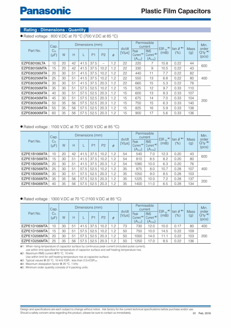
Design and specifications are each subject to change without notice. Ask factory for the current technical specifications before purchase and/or use.
Should a safety concern arise regarding this product, please be sure to contact us immediately.
Plastic Film Capacitors
● Rated voltage : 800 V.DC at 70 °C (700 V.DC at 85 °C)
● Rated voltage : 1100 V.DC at 70 °C (920 V.DC at 85 °C)
● Rated voltage : 1300 V.DC at 70 °C (1100 V.DC at 85 °C)
✽1 : When rising temperature of capacitor surface by continuous peak current (included pulse current),
use within limit specified for temperature of capacitor surface and self heating temperature rise.
✽2 : Maximum RMS current @70 °C, 10 kHz
Use within limit for self heating temperature rise at capacitor surface.
✽3 : Typical values @ 20 °C, 10 kHz ESR : less than 2.5×ESR typ
✽4 : Maximum dissipation factor @ 20 °C, 1 kHz
✽5 : Minimum order quantity consists of 4 packing units.
Part No.
Cap.
CR
(μF)
Dimensions (mm) dv/dt[V/μs]
Permissiblecurrent
ESR typ ✽3
(mΩ)tan d ✽4
(%)Mass(g)
Min. order Q'ty ✽5
(pcs)W H L P1 P2 fPeakCurrent ✽1
(Ao-p)
RMSCurrent ✽2
(Arms)
EZPE80106LTA 10 20 42 41.5 37.5 – 1.2 22 220 7 15.8 0.22 44600
EZPE80156MTA 15 20 42 41.5 37.5 10.2 1.2 22 330 9 10.5 0.22 43
EZPE80206MTA 20 30 51 41.5 37.5 10.2 1.2 22 440 11 7.7 0.22 82
400EZPE80256MTA 25 30 51 41.5 37.5 10.2 1.2 22 550 13 6.8 0.22 80
EZPE80306MTA 30 30 51 41.5 37.5 20.3 1.2 22 660 15 5.3 0.22 78
EZPE80356MTA 35 30 51 57.5 52.5 10.2 1.2 15 525 12 9.7 0.33 110
200
EZPE80406MTA 40 30 51 57.5 52.5 20.3 1.2 15 600 13 8.3 0.33 107
EZPE80456MTA 45 30 51 57.5 52.5 20.3 1.2 15 675 14 7.0 0.33 104
EZPE80506MTA 50 35 56 57.5 52.5 20.3 1.2 15 750 15 6.3 0.33 140
EZPE80556MTA 55 35 56 57.5 52.5 20.3 1.2 15 825 16 5.9 0.33 138
EZPE80606MTA 60 35 56 57.5 52.5 20.3 1.2 15 900 17 5.6 0.33 136
Part No.
Cap.
CR
(μF)
Dimensions (mm) dv/dt[V/μs]
Permissiblecurrent
ESR typ ✽3
(mΩ)tan d ✽4
(%)Mass(g)
Min. order Q'ty ✽5
(pcs)W H L P1 P2 fPeakCurrent ✽1
(Ao-p)
RMSCurrent ✽2
(Arms)
EZPE1B106MTA 10 20 42 41.5 37.5 10.2 1.2 54 540 7.0 12.3 0.20 43600
EZPE1B156MTA 15 30 51 41.5 37.5 10.2 1.2 54 810 8.5 8.2 0.20 80
EZPE1B206MTA 20 30 51 41.5 37.5 20.3 1.2 54 1080 10.0 6.3 0.20 76
400EZPE1B256MTA 25 30 51 57.5 52.5 10.2 1.2 35 875 8.0 10.7 0.28 107
EZPE1B306MTA 30 30 51 57.5 52.5 20.3 1.2 35 1050 9.0 8.5 0.28 103
EZPE1B356MTA 35 35 56 57.5 52.5 20.3 1.2 35 1225 10.0 7.2 0.28 137200
EZPE1B406MTA 40 35 56 57.5 52.5 20.3 1.2 35 1400 11.0 6.5 0.28 134
Part No.
Cap.
CR
(μF)
Dimensions (mm) dv/dt[V/μs]
Permissiblecurrent
ESR typ ✽3
(mΩ)tan d ✽4
(%)Mass(g)
Min. order Q'ty ✽5
(pcs)W H L P1 P2 fPeakCurrent ✽1
(Ao-p)
RMSCurrent ✽2
(Arms)
EZPE1D106MTA 10 30 51 41.5 37.5 10.2 1.2 73 730 12.0 10.0 0.17 80 400
EZPE1D156MTA 15 30 51 57.5 52.5 10.2 1.2 50 750 10.0 14.5 0.22 109
200EZPE1D206MTA 20 30 51 57.5 52.5 20.3 1.2 50 1000 14.0 11.1 0.22 103
EZPE1D256MTA 25 35 56 57.5 52.5 20.3 1.2 50 1250 17.0 8.5 0.22 136
Rating · Dimensions · Quantity
Feb. 201601

Design and specifications are each subject to change without notice. Ask factory for the current technical specifications before purchase and/or use.
Should a safety concern arise regarding this product, please be sure to contact us immediately.
Plastic Film Capacitors
1 2 3 4 5 6 7 8 9 11 12
E Z P E
Product code Dielectric &construction
SuffixRated voltage Capacitance SuffixPin type
10
T
L 2-pin type
M 4-pin type
(Ex.)
45 450 V.DC
52 525 V.DC
57 575 V.DC
63 630 V.DC
● High safety, Self-healing and Self-protecting function built-in● Long product life, High reliability, High moisture resistance● Low loss, Low ESR● Flame retardant● Low profi le design● RoHS directive compliant
For DC fi ltering, DC link circuit
● Solar inverters, Micro inverters● Wind power generation● Industrial power supplies● Inverter circuit in appliances (Air Conditioners etc.)
● Dielectric : Polypropylene fi lm● Electrodes : Metallized dielectric with segmented pattern● Plastic case : UL94 V-0● Sealing : UL94 V-0● Terminals : Tinned wires, 2-pin and 4-pin versions
Features
Metallized Polypropylene Film CapacitorType : EZPE Series (Low profi le type)
Category temperature range (TC) ✽1 −40 °C to +85 °C
Rated voltage(VR) ✽2 450 V.DC, 525 V.DC, 575 V.DC, 630 V.DC(Derating of rated voltage by more than 70 °C ✽3)
Rated capacitance (CR)
450 V.DC 66 μF
525 V.DC 29 μF
575 V.DC 12 μF
630 V.DC 10 μF
Capacitance tolerance ±15 %
Withstanding DC voltageBetween terminals : Rated voltage. (V.DC)×150 %, 10 s
Terminal to case : 2000 V.AC (50 Hz or 60 Hz), 10 s
Insulation resistance (CR) CR > 10000 Ω ∙ F (20 °C, 500 V.DC, 60 s)
✽1 : The temperature of capacitor surface (case)
✽2 : Use for DC voltage only
✽3 : Refer to the page of “DC voltage derating”
Recommended applications
Construction
Explanation of part number
Specifi cations
Dec. 201602

Design and specifications are each subject to change without notice. Ask factory for the current technical specifications before purchase and/or use.
Should a safety concern arise regarding this product, please be sure to contact us immediately.
Plastic Film Capacitors
P1±1.0 P2±1.0
L±1.0
H±
1.0
W±
1.0
DC V μF(a)
(c)
(b)
Panasonic
Marking
(a) Rated voltage
(b) Capacitance
(c) Lot No.
Marking (ex.)
0±0.2
Unit : mm
✽1 : When rising temperature of capacitor surface by continuous peak current (included pulse current),
use within limit specified for temperature of capacitor surface and self heating temperature rise.
✽2 : Maximum RMS current @ 70 °C, 10 kHz
Use within limit for self heating temperature rise at capacitor surface.
✽3 : Typical values @ 20 °C, 10 kHz ESR : less than 2.5×ESR typ
✽4 : Maximum dissipation factor @ 20 °C, 1 kHz
✽5 : Minimum order quantity consists of 4 packing units.
● Rated voltage : 525 V.DC at 70 °C
Part No.
Cap.
CR
(μF)
Dimensions (mm) dv/dt[V/μs]
Permissiblecurrent
ESR typ ✽3
(mΩ)tan d ✽4
(%)Mass(g)
Min. order Q'ty ✽5
(pcs)W H L P1 P2 fPeakCurrent ✽1
(Ao-p)
RMSCurrent ✽2
(Arms)
EZPE52296MTB 29 48.5 23.5 37.0 34.0 20.3 0.8 14 400 3.0 7.0 0.4 50 400
● Rated voltage : 575 V.DC at 70 °C
Part No.
Cap.
CR
(μF)
Dimensions (mm) dv/dt[V/μs]
Permissiblecurrent
ESR typ ✽3
(mΩ)tan d ✽4
(%)Mass(g)
Min. order Q'ty ✽5
(pcs)W H L P1 P2 fPeakCurrent ✽1
(Ao-p)
RMSCurrent ✽2
(Arms)
EZPE57126LTB 12 24.5 19.5 41.5 37.5 – 1.0 22 264 5.0 22.0 0.45 25 800
● Rated voltage : 630 V.DC at 70 °C
Part No.
Cap.
CR
(μF)
Dimensions (mm) dv/dt[V/μs]
Permissiblecurrent
ESR typ ✽3
(mΩ)tan d ✽4
(%)Mass(g)
Min. order Q'ty ✽5
(pcs)W H L P1 P2 fPeakCurrent ✽1
(Ao-p)
RMSCurrent ✽2
(Arms)
EZPE63106LTB 10 24.5 19.5 41.5 37.5 – 1.0 21 210 3.0 22.0 0.45 25 800
Dimensions
● Rated voltage : 450 V.DC at 70 °C
Part No.
Cap.
CR
(μF)
Dimensions (mm) dv/dt[V/μs]
Permissiblecurrent
ESR typ ✽3
(mΩ)tan d ✽4
(%)Mass(g)
Min. order Q'ty ✽5
(pcs)W H L P1 P2 fPeakCurrent ✽1
(Ao-p)
RMSCurrent ✽2
(Arms)
EZPE45666MTB 66 90 24 32.5 27.5 37.5 0.8 5 300 15.0 5.0 0.3 110 200
Rating · Dimensions · Quantity
Dec. 201602

Design and specifications are each subject to change without notice. Ask factory for the current technical specifications before purchase and/or use.
Should a safety concern arise regarding this product, please be sure to contact us immediately.
Plastic Film Capacitors
1 2 3 4 5 6 7 8 9 11 12
E Z P Q
Product code Dielectric &construction
SuffixRated voltage Capacitance SuffixPin type
10
T
L 2-pin type
M 4-pin type
25 250 V.AC
● High Safety (Self-protecting function built-in)● Long product life, High reliability● Low loss, Low ESR● Flame retardant (Case and sealing resin)● RoHS directive compliant● High moisture resistance (85 °C, 85%RH)
For AC fi lter
● Solar inverters● UPS● Industrial power supplies● Inverter circuit in appliances (Air Conditioners etc.)
● Dielectric : Polypropylene fi lm● Electrodes : Metallized dielectric with segmented pattern● Plastic case : UL94 V-0● Sealing : UL94 V-0● Terminals : Tinned wires, 2-pin and 4-pin versions
Construction
Metallized Polypropylene Film CapacitorType : EZPQ Series
Specifi cations
Category temperature range (TC) ✽1 −40 °C to +85 °C
Rated voltage(VR) ✽2 250 V.AC
Rated capacitance (CR) 250 V.DC 12, 22, 36 μF
Capacitance tolerance ±10 %
Withstanding DC voltageBetween terminals : Rated voltage. (V.AC)×175 %, 10 s
Terminal to case : 2000 V.AC (50 Hz or 60 Hz), 10 s
Insulation resistance (CR) CR > 10000 Ω ∙ F (20 °C, 500 V.DC, 60 s)
✽1 : The temperature of capacitor surface (case)
✽2 : Use for AC voltage only
Features
Recommended applications
Explanation of part number
Nov. 201600

Design and specifications are each subject to change without notice. Ask factory for the current technical specifications before purchase and/or use.
Should a safety concern arise regarding this product, please be sure to contact us immediately.
Plastic Film Capacitors
Marking
P1±1
L±0.5
P2±1
0±0.2
4.0
±2
.0H±
0.5
W±
0.5
Marking
P1±1
4.0
±2
.0H±
0.5
0±0.2
L±0.5
W±
0.5
AC V μF(a)(a) Rated voltage
(b) Capacitance
(c) Lot No.(c)
(b)
Panasonic
Marking (ex.)
Unit : mm
● Rated voltage : 250 V.AC
Dimensions
Rating · Dimensions · Quantity
✽1 : Minimum order quantity consists of 4 packing units.
Part No.
Cap.
CR
(μF)
Dimensions (mm) Mass(g)
Min. order Q'ty ✽1
(pcs)W H L P1 P2 f
EZPQ25126LTA 12 22 36 48.5 45.6 – 1.2 80 800
EZPQ25226LTA 22 30 45 57.5 52.5 – 1.2 107 200
EZPQ25366LTA 36 35 56 57.5 52.5 – 1.2 136 200
Nov. 201600
Please contact Factory
CAUTION AND WARNING
The information in this catalog is valid as of January 2018.
1. The electronic components contained in this catalog are designed and produced for use in home electric appliances, office equipment, information equipment,communications equipment, and other general purpose electronic devices. Before use of any of these components for equipment that requires a high degree of safety, such as medical instruments, aerospace equipment, disaster-prevention equipment, security equipment, vehicles (automobile, train, vessel), please be sure to contact our sales representative corporation.
2. When applying one of these components for equipment requiring a high degree of safety, no matter what sort of application it might be, be sure to install a protective circuit or redundancy arrangement to enhance the safety of your equipment. In addition, please carry out the safety test on your own responsibility.
3. When using our products, no matter what sort of equipment they might be used for, be sure to make a written agreement on the specifications with us in advance.
4. Technical information contained in this catalog is intended to convey examples of typical performances and or applications and is not intended to make any warranty with respect to the intellectual property rights or any other related rights of our company or any third parties nor grant any license under such rights.
5. In order to export products in this catalog, the exporter may be subject to the export license requirement under the Foreign Exchange and Foreign Trade Law of Japan.
6. No ozone-depleting substances (ODSs) under the Montreal Protocol are used in the manufacturing processes of Automotive & Industrial Systems Company, Panasonic Corporation.