Embed Size (px)
Citation preview
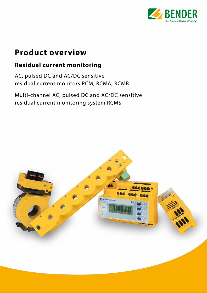
Product overviewResidual current monitoring
AC, pulsed DC and AC/DC sensitive residual current monitors RCM, RCMA, RCMB
Multi-channel AC, pulsed DC and AC/DC sensitive residual current monitoring system RCMS
2
RCMA/RCMB
K1 K2 K3 K4 K5 K6 ON/COM
012 3
4 5 6 789
x1
012 3
4 5 6 789 x10
A B + -
Type A Type B Type A Type B
CTAC…WR…SWS…
CTUB100CTUB100
CTAC…WR…SWS…WF…
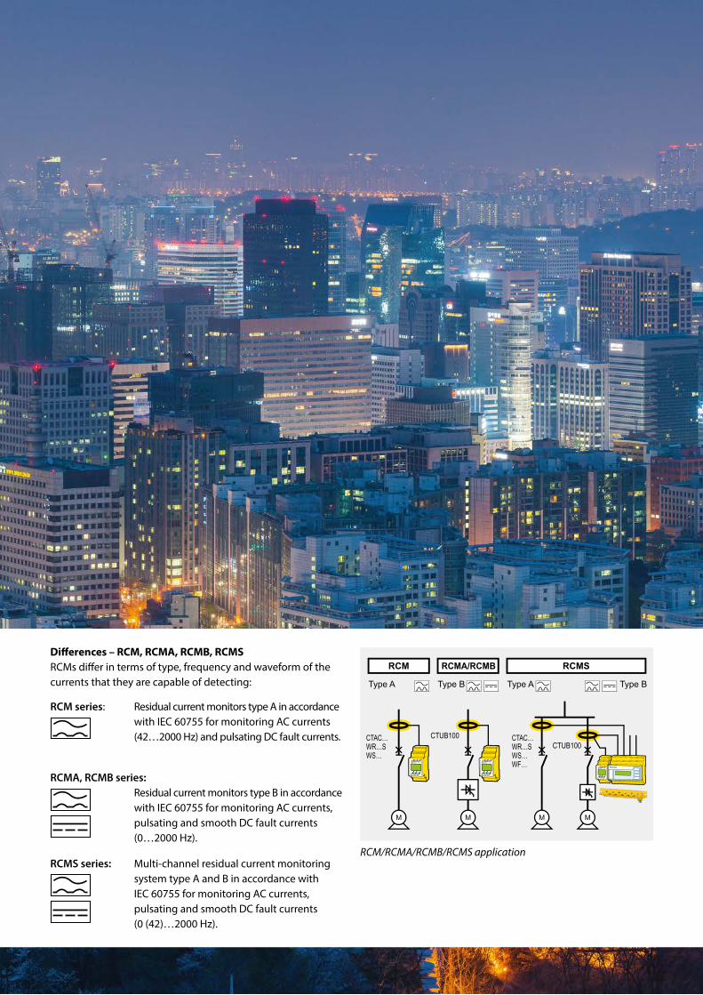
RCM/RCMA/RCMB/RCMS application
Differences – RCM, RCMA, RCMB, RCMSRCMs differ in terms of type, frequency and waveform of the currents that they are capable of detecting:
RCM series: Residual current monitors type A in accordance with IEC 60755 for monitoring AC currents (42…2000 Hz) and pulsating DC fault currents.
RCMA, RCMB series: Residual current monitors type B in accordance
with IEC 60755 for monitoring AC currents, pulsating and smooth DC fault currents (0…2000 Hz).
RCMS series: Multi-channel residual current monitoring system type A and B in accordance with IEC 60755 for monitoring AC currents, pulsating and smooth DC fault currents (0 (42)…2000 Hz).

3
In practice Products Residual current monitoring with RCM ...................................... 4
Your benefit from RCM/RCMA/RCMS monitoring .................. 6
Periodic Verification – Reliable operation of the electrical installation ................... 7
RCM/RCMS in practice – Protection against unexpected shutdown and
fire hazards ....................................................................................... 8
RCMA in practice – Increased safety in case of smooth DC fault currents ....... 9
RCMS in practice – For reliable and EMC friendly electrical installations ...... 10
– Monitoring the Central Earthing Point (CEP) ..................... 11
– Monitoring currents in N conductors ................................... 12
– Application example for an RCMS system in an office or a computer room ............................................. 13
Residual current monitors RCM ...................................................14
AC/DC sensitive residual current monitors RCMA ..........................................................16
AC/DC sensitive residual current monitors RCMB ........................................................ 17
Residual current monitoring system RCMS ............................ 18
AC/DC sensitive residual current monitoring system RCMS ............................ 20
Selection guide ................................................................................. 21
AC/DC sensitive residual current monitoring modules .... 22
Measuring current transformers for residual current monitors and systems .....................................23
Accessories for residual current monitors and monitoring systems .................................................................25
Bender monitoring systems – seamless communication ...........................................................26
Retrofit ..................................................................................................27
POWERSCOUT® Find out today what won't happen tomorrow .......................28
Support during all stages ...............................................................30
Bender. So that your world is safer. .............................................31
Find out today what won't happen tomorrow
Signalling instead of shutdownReporting critical operating states today to avoid unwanted events, such as interruptions to operation, costly damage to property or even physical injuries.
Highest possible system availability thanks to innovative measurement technologyPeriodic testing and monitoring of electrical installations and equipment is expensive in terms of time and money. Besides that, many installations may not be disconnected because they have to be constantly available. Your time and cost-saving alternative are Bender's residual current monitoring systems for earthed power supplies (TN/TT systems). They monitor electrical installations for residual and/or fault currents, display the current measured value and signal when pre-set response values are exceeded as required by the relevant standards. The continuous residual current monitoring
of electrical installations and equipment assists with preventive maintenance in accordance with the German Social Accident Insurance (DGUV) regulation 3 (formerly BGV A3).
Safe power supply – in all areasThe range of application of residual current monitoring systems extends from data centres, banks, insurances and office buildings, hospitals, traffic engineering to energy supply and distribution, broadcasting stations, communication technology systems and continuous production processes.
5-year guarantee for the latest measurement technologyFor decades, Bender residual current monitoring has been a name for the latest “Made in Germany” measurement technology as well as for durability and quality. In the light of the above, Bender offers an exceptionally long warranty period of five years.
4
Information advantage – a key success factorDaily international business activities, continuous competitive pressure, the impact of soaring costs and operational availability around the clock – this requires the maximum possible level of electrical safety for power supplies in industrial, residential and functional buildings. Continuous monitoring of safety-relevant circuits for fault, residual and operating currents as well as for stray currents. You gain information regarding potential critical operating conditions at an early stage, thus avoiding:
Danger to persons
Fire damage and material damage
EMC interferences
Your benefits:
Preventive electrical safety for man and machine
High availability of power supply systems
Reducing EMC interferences
Time and cost-optimised maintenance
Significant reduction of operating costs and cost risks
Saving potential thanks to periodic verification according to the German Social Accident Insurance (DGUV) regulation 3
Residual current monitoring with RCM – to increase system availability and reduce costs
Innovative measurement technology for all types of fault currentsModern loads, such as variable-speed drives or switched-mode power supplies generate fault currents that have nothing in common with the good old sine wave. Today, a wide range of harmonics in most versatile waveforms exist in every power supply system. The solution: AC/DC sensitive residual current monitoring (true r.m.s. value measurement) and analysis of the harmonics.
Universal residual current monitoring for:
Data centres, EDP equipment and systems
Banks, insurance companies
Office and administration buildings
Hospitals, medical practices
Power generation and distribution
Power stations
TV and broadcasting stations
Communication technology systems
Traffic engineering (airports, railway, ships, etc.)
Continuous production processes (even with variable-speed drives)
and many more facilities.
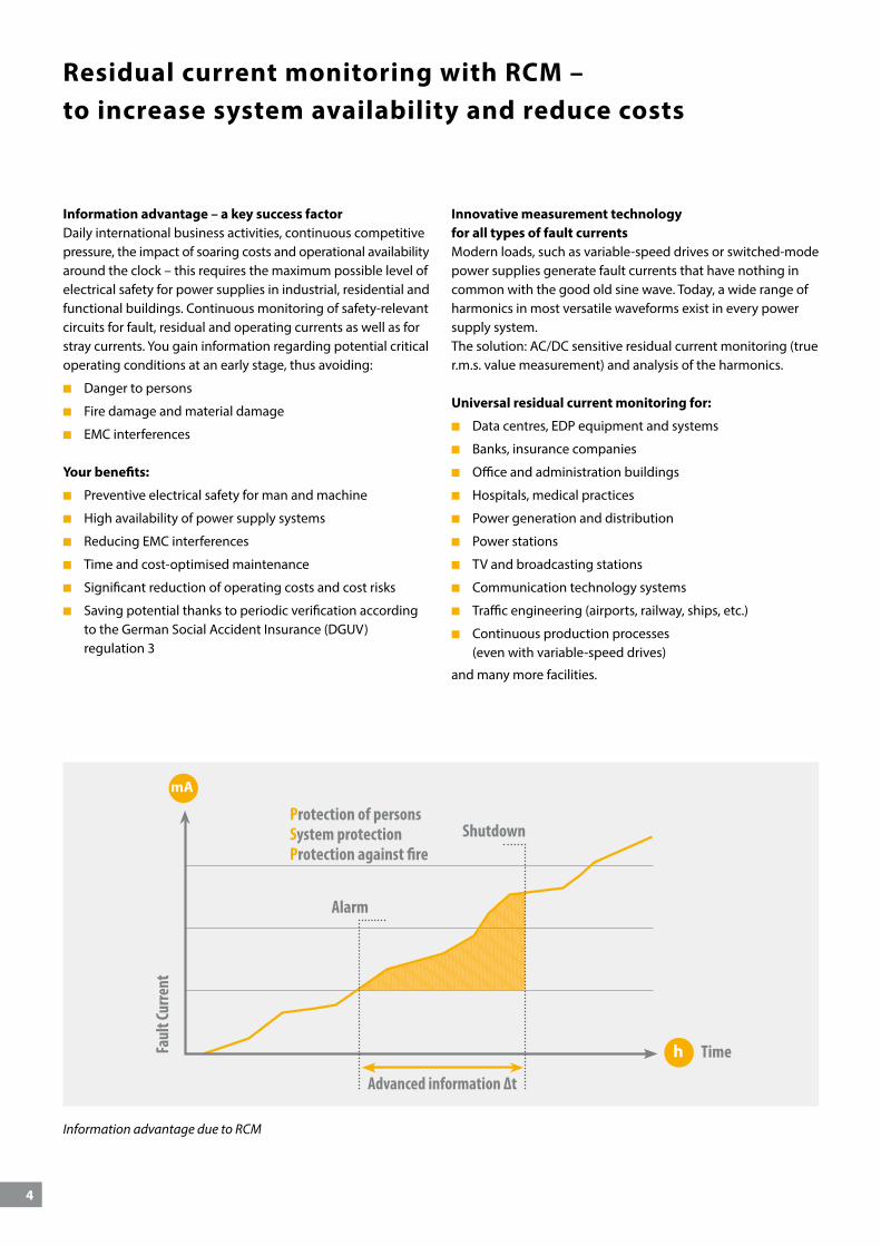
Information advantage due to RCM
mA
h Time
Alarm
ShutdownProtection of personsSystem protectionProtection against fire
Advanced information ∆t
Faul
t Cur
rent
5
The difference between RCMs and RCDsRCMs (residual current monitors) monitor residual currents in electrical installations, indicate the current value and signal when the response values are exceeded. The devices are designed for signalling and/or switching. They comply with DIN EN 62020 (VDE 0663) “Electrical accessories – Residual current monitors for household and similar use (RCMs) (IEC 62020)”.
In contrast to RCMs, the intended use of RCDs (residual current protective devices) is to provide protection in electrical installations in accordance with the standard IEC 60364, e.g. in bathrooms. RCDs always cause a shutdown.
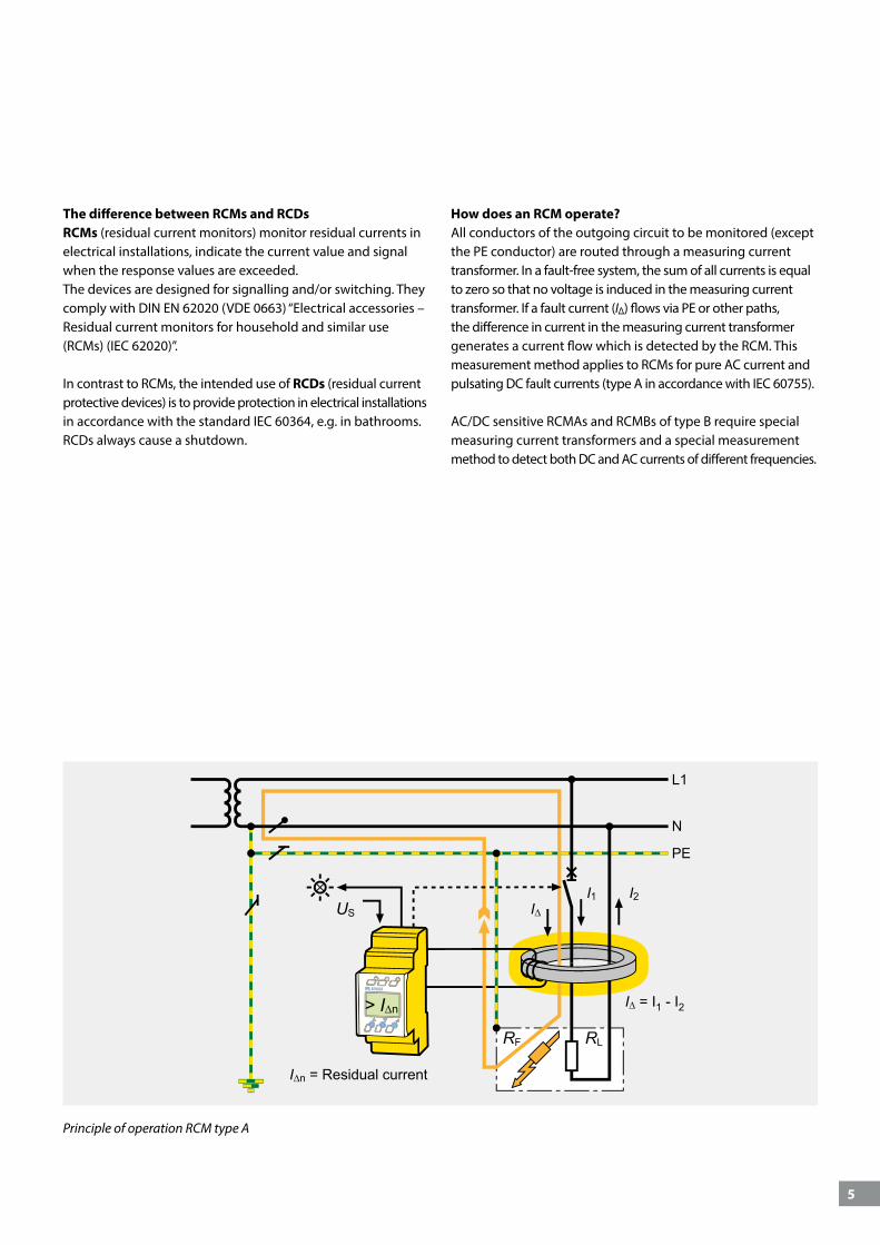
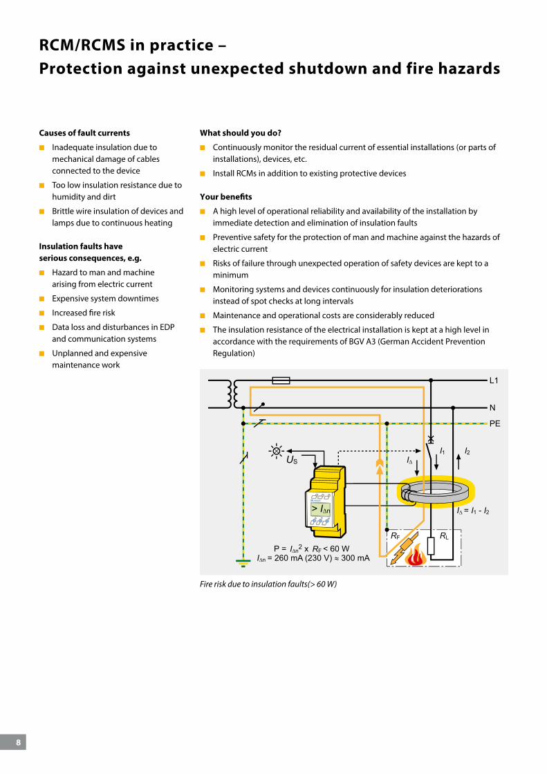
How does an RCM operate?All conductors of the outgoing circuit to be monitored (except the PE conductor) are routed through a measuring current transformer. In a fault-free system, the sum of all currents is equal to zero so that no voltage is induced in the measuring current transformer. If a fault current (I∆) flows via PE or other paths, the difference in current in the measuring current transformer generates a current flow which is detected by the RCM. This measurement method applies to RCMs for pure AC current and pulsating DC fault currents (type A in accordance with IEC 60755).
AC/DC sensitive RCMAs and RCMBs of type B require special measuring current transformers and a special measurement method to detect both DC and AC currents of different frequencies.
I∆ = I1 - I2
I∆I1 I2
US
RF RL
> I∆n
I∆n = Residual current
Principle of operation RCM type A
6
Your benefit from RCM/RCMA/RCMS monitoring
Increased fire protection
Detecting potential fire hazards caused by high fault currents as soon as they occur
N conductor overload or interruption are signalled at an early stage
Preventing material damage due to unintentional displacement of the star point caused by N conductor interruption
Avoiding consequential costs resulting from material and ecological damage
Improved economic efficiency
Maintenance and operating expenses are considerably reduced
Avoiding expensive and unplanned system downtimes through information at an early stage
Higher productivity through increased operational reliability
Saving of costs through lower insurance premiums
Supporting business decisions on investments by recognising weak points in the electrical installation
Comprehensive information
Clear information centrally indicated on an LC display
Transparency of all safety-related information through data transfer via bus systems and integration into LAN/WAN networks
Easy integration into facility management systems via field bus, OPC and Ethernet (TCP/IP)
Cost reduction through the use of existing communication architecture (Ethernet)
Optimised maintenance
Immediate information by centralised or distributed alarm messages
Optimised planning of time and personnel resources through complete documentation and precise indication of the fault location
Fast, preventive intervention by remote diagnostics and remote administration via LAN or WAN network
Higher operational and system safety
Preventive safety for the protection of man and machine against the hazards of electric current
Risks of failure through unexpected operation of safety devices are kept to a minimum
Monitoring systems and devices continuously for insulation deteriorations instead of spot checks at long intervals
Detecting potential faults in newly installed electrical systems or during the commissioning of new devices immediately
Additional safety by monitoring TN-S systems for unwanted N-PE connections
Alarm messages either for signalling or switching off
ON
7
Periodic Verification – Reliable operation of the electrical installation
For reliable operation of the electrical installation, periodic verification in accordance with IEC 60364-6 is required. The responsible electrically skilled person determines the test intervals during risk assessment. Recommendations can be extracted from the applicable regulations and standards. For example:
IEC 60364-6
EN 50110-1
DGUV regulation 3 (formerly BGV A3)
The employer has to ensure that electrical installations and equipment are tested for its proper working condition.
Prior to commissioning
At fixed intervals
The testing principles usually comprise three steps
Visual inspection
Testing and measuring of protective measures, insulation resistances, loop resistances
Functional test
All the tests – with the exception of insulation measurements – can be carried out while the electrical installation is operating. For insulation resistance measurements, electrical installations must be disconnected.
Problem: In installations where high availability is required, a shutdown is not possible. These include:
Communication systems
Data centres
Banks, insurance companies
Office buildings
Industry
In these cases, insulation measurement cannot be carried out.
What should you do?The responsible electrically skilled person has to perform a risk assessment according to the German Ordinance on Industrial Safety and Health to determine the type, scope and interval for periodic testing.
Continuous residual current monitoring (RCMS) permits modified test intervals which meet practical requirements. This way, the electrical installation can be disconnected if continued deterioration in the insulation is detected.
Only faulty stationary electrical installations and equipment have to be disconnected, repaired, tested and put in operation after the occurrence of a common alarm message from the RCMS.
Fault-free installations and equipment do not need to be disconnected for insulation tests. Hence, the test interval for an insulation measurement is determined by an RCMS alarm.
Your benefits
Test intervals for insulation measurements adapted to a practical application
Increased personnel, fire and installation protection
Saving costs through adapted, practical-oriented test intervals
Continuous monitoring of the insulation level
The load, which is the main disturber of any electrical system, is additionally monitored by means of RCM technology
“Can you disconnect your electrical installation for the purpose of insulation measurement?”
Essential parts of the electrical installation that cannot be disconnected should be monitored using a permanently installed residual current monitoring system (RCMS) and the alarm message should be sent to the responsible electrically skilled person.
RCMS +
electrically
skilled person
?Classical
insulation
measurement
8
RCM/RCMS in practice – Protection against unexpected shutdown and fire hazards
I∆n
I∆ = I1 - I2
I∆
> I∆n
USI1 I2
I∆n RF
RF RL
Fire risk due to insulation faults(> 60 W)
Causes of fault currents
Inadequate insulation due to mechanical damage of cables connected to the device
Too low insulation resistance due to humidity and dirt
Brittle wire insulation of devices and lamps due to continuous heating
Insulation faults have serious consequences, e.g.
Hazard to man and machine arising from electric current
Expensive system downtimes
Increased fire risk
Data loss and disturbances in EDP and communication systems
Unplanned and expensive maintenance work
What should you do?
Continuously monitor the residual current of essential installations (or parts of installations), devices, etc.
Install RCMs in addition to existing protective devices
Your benefits
A high level of operational reliability and availability of the installation by immediate detection and elimination of insulation faults
Preventive safety for the protection of man and machine against the hazards of electric current
Risks of failure through unexpected operation of safety devices are kept to a minimum
Monitoring systems and devices continuously for insulation deteriorations instead of spot checks at long intervals
Maintenance and operational costs are considerably reduced
The insulation resistance of the electrical installation is kept at a high level in accordance with the requirements of BGV A3 (German Accident Prevention Regulation)
9
RCMA in practice – Increased safety in case of smooth DC fault currents
IF
IF
RF
IF
RF
IF
RF
IF
IF
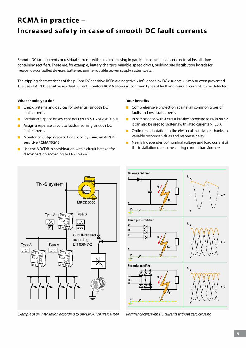
Rectifier circuits with DC currents without zero crossing
Circuit-breakeraccording toEN 60947-2
TN-S system
Type A
Type A Type A
Type B
MRCDB300
Example of an installation according to DIN EN 50178 (VDE 0160)
Smooth DC fault currents or residual currents without zero crossing in particular occur in loads or electrical installations containing rectifiers. These are, for example, battery chargers, variable-speed drives, building site distribution boards for frequency-controlled devices, batteries, uninterruptible power supply systems, etc.
The tripping characteristics of the pulsed DC sensitive RCDs are negatively influenced by DC currents > 6 mA or even prevented. The use of AC/DC sensitive residual current monitors RCMA allows all common types of fault and residual currents to be detected.
What should you do?
Check systems and devices for potential smooth DC fault currents
For variable-speed drives, consider DIN EN 50178 (VDE 0160).
Assign a separate circuit to loads involving smooth DC fault currents
Monitor an outgoing circuit or a load by using an AC/DC sensitive RCMA/RCMB
Use the MRCDB in combination with a circuit breaker for disconnection according to EN 60947-2
Your benefits
Comprehensive protection against all common types of faults and residual currents
In combination with a circuit breaker according to EN 60947-2 it can also be used for systems with rated currents > 125 A
Optimum adaptation to the electrical installation thanks to variable response values and response delay
Nearly independent of nominal voltage and load current of the installation due to measuring current transformers
10
RCMS in practice – for reliable and EMC friendly electrical installations
RCMS – the plus point for high availability of power suppliesPlanners of buildings and electrical installations play a major role when electrical safety and high availability of power supplies are concerned. Already during the planning phase, the foundation for further smooth operation can be laid. With the use of multi-channel RCMS residual current monitoring systems, power supplies can be monitored, AC, pulsed DC and AC/DC sensitive, at critical points for:
Fault or residual currents
Operating currents
Stray currents
Currents in N and PE conductors
The RCMS150 is particularly suitable for final circuits with 4x4 mm² or 2x6 mm²
In this way a substantial contribution is made to obtain a high level of availability of the power supply.
The hazards of uncontrolled currentsResidual currents or fault currents caused by insulation faults can affect the system and operational safety. Even when the electrical installations have been designed and erected by planners and builders in conformance with the standards, modern loads, such as PCs, copiers etc. increasingly cause malfunctions.
Causes:
Stray currents
N conductor overload caused by harmonics
Interruptions of PE and N conductors
Effects:
Unwanted interruptions to operation
Fire damage
Impact on protective devices
Inexplicable malfunctions
Inexplicable damage to fire alarm, telecommunication and EDP systems
Data loss
Damage due to corrosion to pipes, lightning protection systems and earth conductors
High operational costs and maintenance costs
11
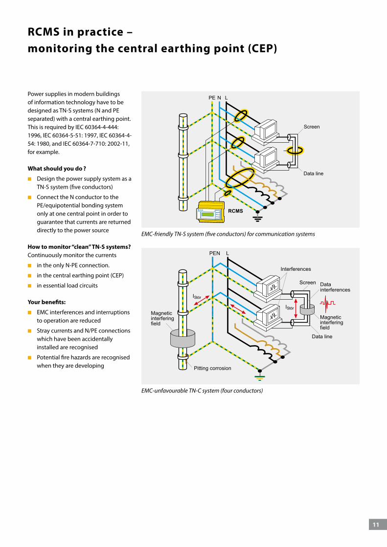
RCMS in practice –monitoring the central earthing point (CEP)
Power supplies in modern buildings of information technology have to be designed as TN-S systems (N and PE separated) with a central earthing point. This is required by IEC 60364-4-444: 1996, IEC 60364-5-51: 1997, IEC 60364-4-54: 1980, and IEC 60364-7-710: 2002-11, for example.
What should you do ?
Design the power supply system as a TN-S system (five conductors)
Connect the N conductor to the PE/equipotential bonding system only at one central point in order to guarantee that currents are returned directly to the power source
How to monitor “clean” TN-S systems?Continuously monitor the currents
in the only N-PE connection.
in the central earthing point (CEP)
in essential load circuits
Your benefits:
EMC interferences and interruptions to operation are reduced
Stray currents and N/PE connections which have been accidentally installed are recognised
Potential fire hazards are recognised when they are developing
EMC-unfavourable TN-C system (four conductors)
EMC-friendly TN-S system (five conductors) for communication systems
12
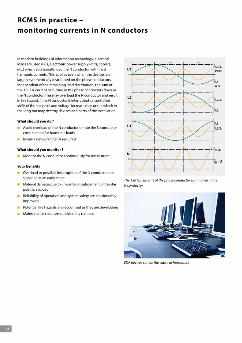
RCMS in practice – monitoring currents in N conductors
EDP devices can be the cause of harmonics
In modern buildings of information technology, electrical loads are used (PCs, electronic power supply units, copiers, etc.) which additionally load the N conductor with third harmonic currents. This applies even when the devices are largely symmetrically distributed on the phase conductors. Independent of the remaining load distribution, the sum of the 150 Hz current occurring in the phase conductors flows in the N conductor. This may overload the N conductor and result in fire hazard. If the N conductor is interrupted, uncontrolled shifts of the star point and voltage increase may occur, which in the long run may destroy devices and parts of the installation.
What should you do ?
Avoid overload of the N conductor or rate the N conductor cross section for harmonic loads
Install a network filter, if required
What should you monitor ?
Monitor the N conductor continuously for overcurrent
Your benefits
Overload or possible interruption of the N conductor are signalled at an early stage
Material damage due to unwanted displacement of the star point is avoided
Reliability of operation and system safety are considerably improved
Potential fire hazards are recognised as they are developing
Maintenance costs are considerably reduced
The 150 Hz currents of the phase conductor summarise in the N conductor
13
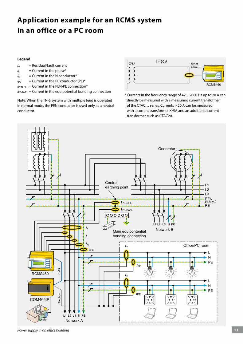
Application example for an RCMS systemin an office or a PC room
IPEN-PE
IPE-PAS
I∆
I∆
IL
INIPE
IPE
I∆
IPE
COM465IP
Mod
bus
Power supply in an office building
Legend
l∆ = Residual/fault currentIL = Current in the phase* lN = Current in the N conductor* lPE = Current in the PE conductor (PE)* lPEN-PE = Current in the PEN-PE connection* lPE-PAS = Current in the equipotential bonding connection
Note: When the TN-S system with multiple feed is operated in normal mode, the PEN conductor is used only as a neutral conductor.
* Currents in the frequency range of 42…2000 Hz up to 20 A can directly be measured with a measuring current transformer of the CTAC… series. Currents > 20 A can be measured with a current transformer X/5A and an additional current transformer such as CTAC20.
seriesCTAC…
X/5AI > 20 A
14
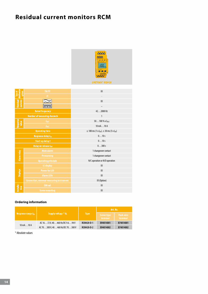
Residual current monitors RCM
LINETRAXX® RCM420
Type
of
distri
butio
n sys
tem
TN/TT
IT –
Resid
ual
curre
nts
–
Rated frequency 42…2000 Hz
Number of measuring channels 1
Resp
onse
va
lue lΔn1 50…100 % x lΔn2
lΔn2 10 mA…10 A
Operating time ≤ 180 ms (1 x I∆n), ≤ 30 ms (5 x I∆n)
Response delay ton 0…10 s
Start-up delay t 0…10 s
Delay on release toff 0…300 s
Alar
m re
lay Main alarm 1 changeover contact
Prewarning 1 changeover contact
Operating principle N/C operation or N/O operation
Disp
lays
LC display
Power On LED
Alarm LEDs
Connection, external measuring instrument (Option)
Inst
alla
-tio
n DIN rail
Screw mounting
Ordering information
Response range I∆n Supply voltage 1) US TypeArt. No.
Screw-type terminal
Push-wire terminal
10 mA…10 AAC 16…72 V, 40…460 Hz/DC 9.6…94 V RCM420-D-1 B94014001 B74014001
AC 70…300 V, 40…460 Hz/DC 70…300 V RCM420-D-2 B94014002 B74014002
1) Absolute values
15
I∆n
US
I∆nUS RF
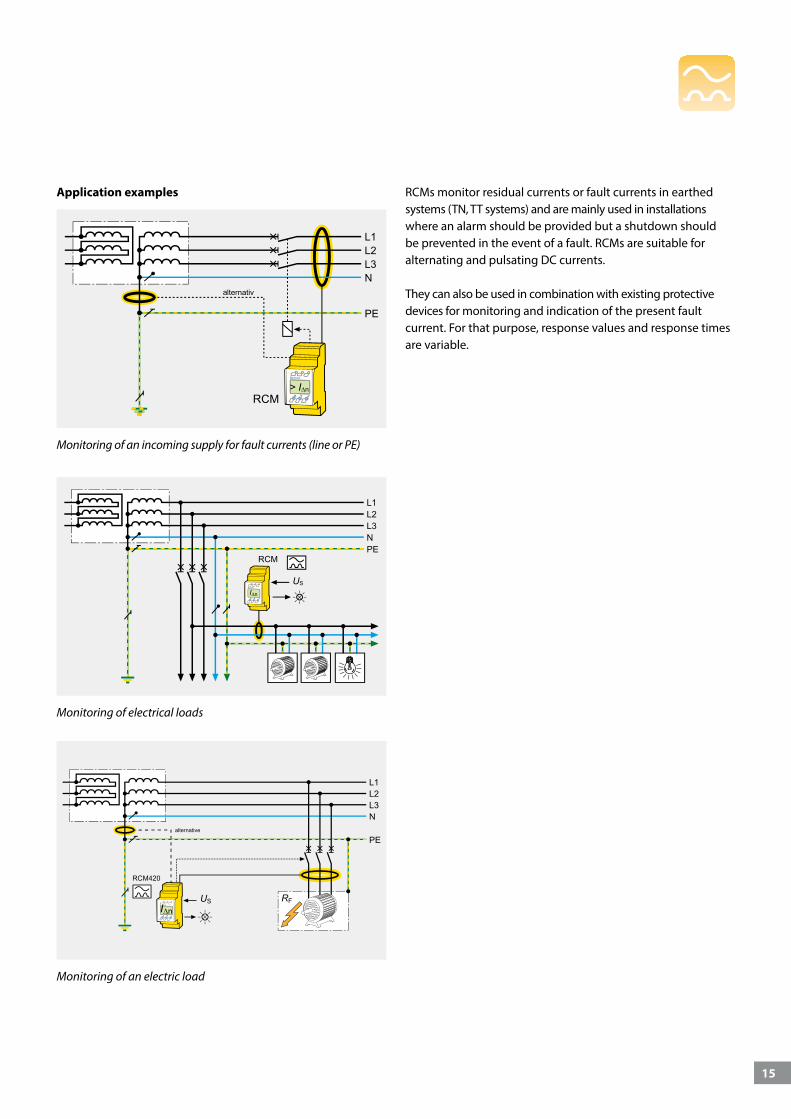
RCMs monitor residual currents or fault currents in earthed systems (TN, TT systems) and are mainly used in installations where an alarm should be provided but a shutdown should be prevented in the event of a fault. RCMs are suitable for alternating and pulsating DC currents.
They can also be used in combination with existing protective devices for monitoring and indication of the present fault current. For that purpose, response values and response times are variable.
> I∆n
Monitoring of an electric load
Monitoring of electrical loads
Monitoring of an incoming supply for fault currents (line or PE)
Application examples
16
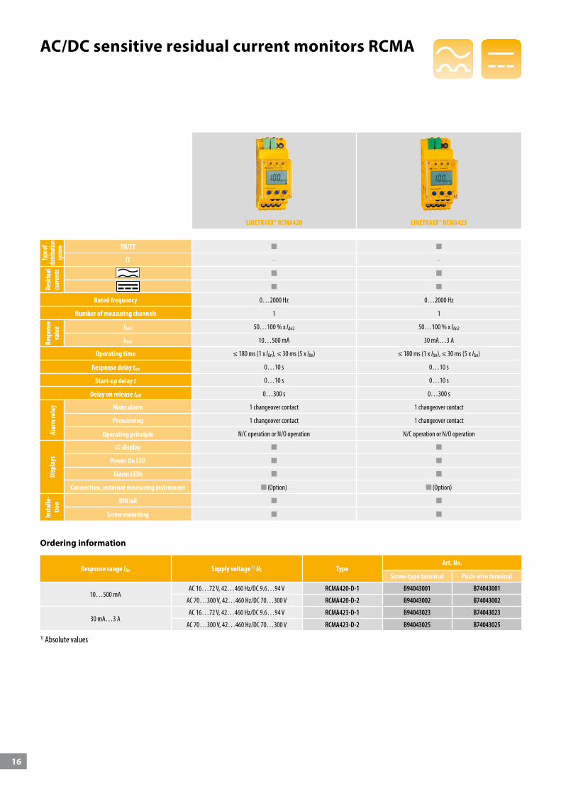
AC/DC sensitive residual current monitors RCMA
Ordering information
LINETRAXX® RCMA420 LINETRAXX® RCMA423
Type
of
distri
butio
n sys
tem
TN/TT
IT – –
Resid
ual
curre
nts
Rated frequency 0…2000 Hz 0…2000 Hz
Number of measuring channels 1 1
Resp
onse
va
lue lΔn1 50…100 % x lΔn2 50…100 % x lΔn2
lΔn2 10…500 mA 30 mA…3 A
Operating time ≤ 180 ms (1 x I∆n), ≤ 30 ms (5 x I∆n) ≤ 180 ms (1 x I∆n), ≤ 30 ms (5 x I∆n)
Response delay ton 0…10 s 0…10 s
Start-up delay t 0…10 s 0…10 s
Delay on release toff 0…300 s 0…300 s
Alar
m re
lay Main alarm 1 changeover contact 1 changeover contact
Prewarning 1 changeover contact 1 changeover contact
Operating principle N/C operation or N/O operation N/C operation or N/O operation
Disp
lays
LC display
Power On LED
Alarm LEDs
Connection, external measuring instrument (Option) (Option)
Inst
alla
-tio
n DIN rail
Screw mounting
Response range I∆n Supply voltage 1) US TypeArt. No.
Screw-type terminal Push-wire terminal
10…500 mAAC 16…72 V, 42…460 Hz/DC 9.6…94 V RCMA420-D-1 B94043001 B74043001
AC 70…300 V, 42…460 Hz/DC 70…300 V RCMA420-D-2 B94043002 B74043002
30 mA…3 AAC 16…72 V, 42…460 Hz/DC 9.6…94 V RCMA423-D-1 B94043023 B74043023
AC 70…300 V, 42…460 Hz/DC 70…300 V RCMA423-D-2 B94043025 B74043025
1) Absolute values
17
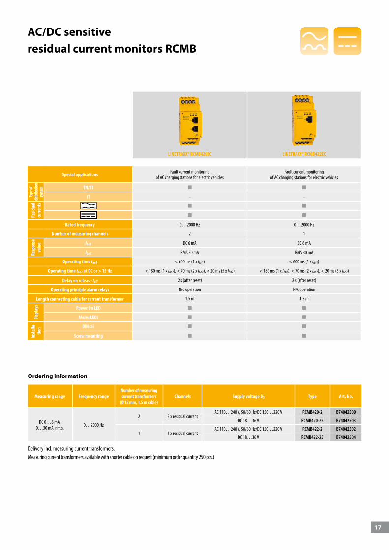
AC/DC sensitive residual current monitors RCMB
Ordering information
LINETRAXX® RCMB420EC LINETRAXX® RCMB422EC
Special applications Fault current monitoring of AC charging stations for electric vehicles
Fault current monitoring of AC charging stations for electric vehicles
Type
of
distri
butio
n sys
tem
TN/TT
IT – –
Resid
ual
curre
nts
Rated frequency 0…2000 Hz 0…2000 Hz
Number of measuring channels 2 1
Resp
onse
va
lue lΔn1 DC 6 mA DC 6 mA
lΔn2 RMS 30 mA RMS 30 mA
Operating time tae1 < 600 ms (1 x I∆n1) < 600 ms (1 x I∆n1)
Operating time tae2 at DC or > 15 Hz < 180 ms (1 x I∆n2), < 70 ms (2 x I∆n2), < 20 ms (5 x I∆n2) < 180 ms (1 x I∆n2), < 70 ms (2 x I∆n2), < 20 ms (5 x I∆n2)
Delay on release toff 2 s (after reset) 2 s (after reset)
Operating principle alarm relays N/C operation N/C operation
Length connecting cable for current transformer 1.5 m 1.5 m
Disp
lays Power On LED
Alarm LEDs
Inst
alla
-tio
n DIN rail
Screw mounting
Measuring range Frequency rangeNumber of measuringcurrent transformers
(Ø 15 mm, 1.5 m cable)Channels Supply voltage US Type Art. No.
DC 0…6 mA,0…30 mA r.m.s. 0…2000 Hz
2 2 x residual current AC 110…240 V, 50/60 Hz/DC 150…220 V RCMB420-2 B74042500
DC 18…36 V RCMB420-25 B74042503
1 1 x residual current AC 110…240 V, 50/60 Hz/DC 150…220 V RCMB422-2 B74042502
DC 18…36 V RCMB422-25 B74042504
Delivery incl. measuring current transformers.Measuring current transformers available with shorter cable on request (minimum order quantity 250 pcs.)
18
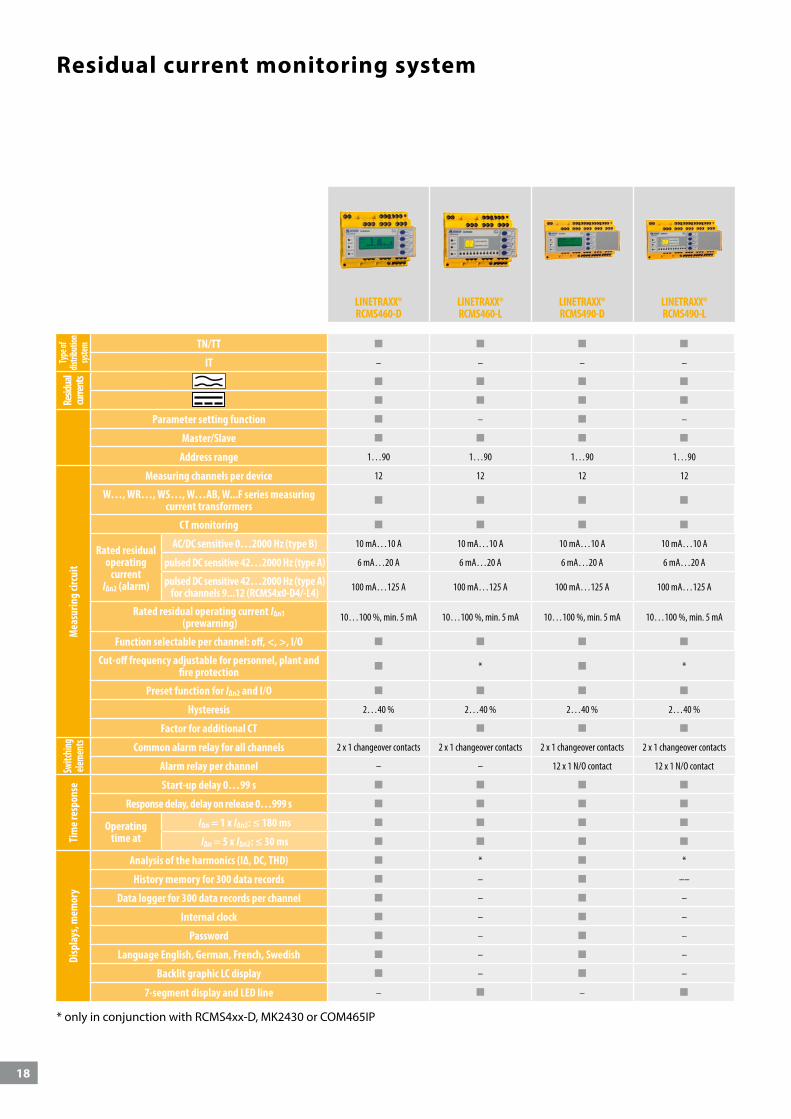
LINETRAXX® RCMS460-D
LINETRAXX® RCMS460-L
LINETRAXX® RCMS490-D
LINETRAXX® RCMS490-L
Type
of
distri
butio
n sys
tem
TN/TT
IT – – – –
Resid
ual
curre
nts
Parameter setting function – –
Master/Slave
Address range 1…90 1…90 1…90 1…90
Mea
surin
g cir
cuit
Measuring channels per device 12 12 12 12
W…, WR…, WS…, W…AB, W...F series measuring current transformers
CT monitoring
Rated residual operating
current I∆n2 (alarm)
AC/DC sensitive 0…2000 Hz (type B) 10 mA…10 A 10 mA…10 A 10 mA…10 A 10 mA…10 A
pulsed DC sensitive 42…2000 Hz (type A) 6 mA…20 A 6 mA…20 A 6 mA…20 A 6 mA…20 A
pulsed DC sensitive 42…2000 Hz (type A) for channels 9...12 (RCMS4x0-D4/-L4) 100 mA…125 A 100 mA…125 A 100 mA…125 A 100 mA…125 A
Rated residual operating current I∆n1 (prewarning) 10…100 %, min. 5 mA 10…100 %, min. 5 mA 10…100 %, min. 5 mA 10…100 %, min. 5 mA
Function selectable per channel: off, <, >, I/O
Cut-off frequency adjustable for personnel, plant and fire protection * *
Preset function for I∆n2 and I/O
Hysteresis 2…40 % 2…40 % 2…40 % 2…40 %
Factor for additional CT
Switc
hing
eleme
nts
Common alarm relay for all channels 2 x 1 changeover contacts 2 x 1 changeover contacts 2 x 1 changeover contacts 2 x 1 changeover contacts
Alarm relay per channel – – 12 x 1 N/O contact 12 x 1 N/O contact
Tim
e res
pons
e Start-up delay 0…99 s
Response delay, delay on release 0…999 s
Operating time at
I∆n = 1 x I∆n2: ≤ 180 ms
I∆n = 5 x I∆n2: ≤ 30 ms
Disp
lays
, mem
ory
Analysis of the harmonics (I∆, DC, THD) * *
History memory for 300 data records – ––
Data logger for 300 data records per channel – –
Internal clock – –
Password – –
Language English, German, French, Swedish – –
Backlit graphic LC display – –
7-segment display and LED line – –
* only in conjunction with RCMS4xx-D, MK2430 or COM465IP
Residual current monitoring system
19
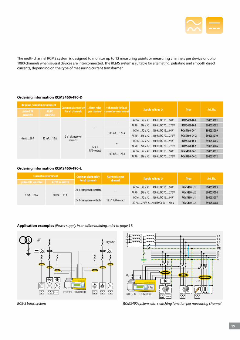
The multi-channel RCMS system is designed to monitor up to 12 measuring points or measuring channels per device or up to 1080 channels when several devices are interconnected. The RCMS system is suitable for alternating, pulsating and smooth direct currents, depending on the type of measuring current transformer.
Residual current measurementCommon alarm relay
for all channelsAlarm relay per channel
4 channels for load current measurement Supply voltage US Type Art. No.pulsed DC
sensitiveAC/DC
sensitive
6 mA…20 A 10 mA…10 A 2 x 1 changeover contacts
–
–AC 16…72 V, 42…460 Hz/DC 16…94 V RCMS460-D-1 B94053001
AC 70…276 V, 42…460 Hz/DC 70…276 V RCMS460-D-2 B94053002
100 mA…125 AAC 16…72 V, 42…460 Hz/DC 16…94 V RCMS460-D4-1 B94053009
AC 70…276 V, 42…460 Hz/DC 70…276 V RCMS460-D4-2 B94053010
12 x 1 N/O contact
–AC 16…72 V, 42…460 Hz/DC 16…94 V RCMS490-D-1 B94053005
AC 70…276 V, 42…460 Hz/DC 70…276 V RCMS490-D-2 B94053006
100 mA…125 AAC 16…72 V, 42…460 Hz/DC 16…94 V RCMS490-D4-1 B94053011
AC 70…276 V, 42…460 Hz/DC 70…276 V RCMS490-D4-2 B94053012
Ordering information RCMS460/490-D
Current measurement Common alarm relay for all channels
Alarm relay per channel Supply voltage US Type Art. No.
pulsed DC sensitive AC/DC sensitive
6 mA…20 A 10 mA…10 A
2 x 1 changeover contacts –AC 16…72 V, 42…460 Hz/DC 16…94 V RCMS460-L-1 B94053003
AC 70…276 V, 42…460 Hz/DC 70…276 V RCMS460-L-2 B94053004
2 x 1 changeover contacts 12 x 1 N/O contactAC 16…72 V, 42…460 Hz/DC 16…94 V RCMS490-L-1 B94053007
AC 70…276 V, 2…460 Hz/DC 70…276 V RCMS490-L-2 B94053008
Ordering information RCMS460/490-L
RCMS490 system with switching function per measuring channelRCMS basic system
Application examples (Power supply in an office building, refer to page 11)
STEP-PS RCMS490STEP-PS RCMS460-D
20
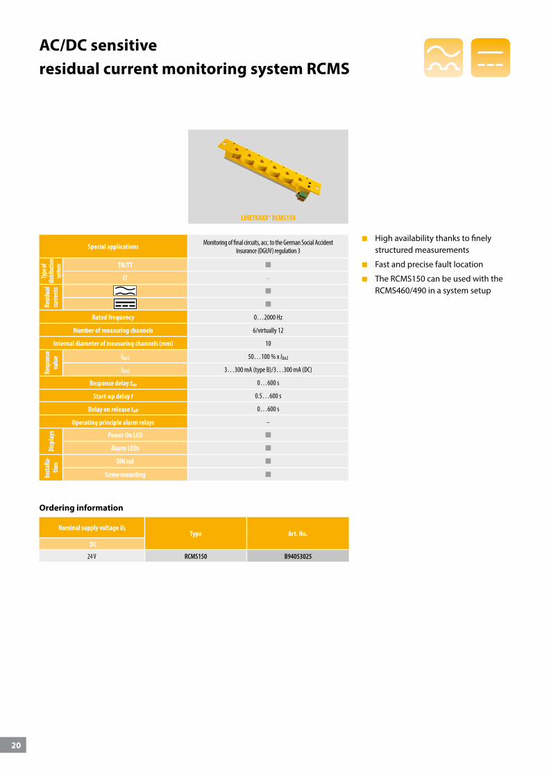
AC/DC sensitive residual current monitoring system RCMS
LINETRAXX® RCMS150
Special applications Monitoring of final circuits, acc. to the German Social Accident Insurance (DGUV) regulation 3
Type
of
distri
butio
n sys
tem
TN/TT
IT –
Resid
ual
curre
nts
Rated frequency 0…2000 Hz
Number of measuring channels 6/virtually 12
Internal diameter of measuring channels (mm) 10
Resp
onse
va
lue lΔn1 50…100 % x IΔn2
lΔn2 3…300 mA (type B)/3…300 mA (DC)
Response delay ton 0…600 s
Start-up delay t 0.5…600 s
Delay on release toff 0…600 s
Operating principle alarm relays –
Disp
lays Power On LED
Alarm LEDs
Inst
alla
-tio
n DIN rail
Screw mounting
Nominal supply voltage USType Art. No.
DC
24 V RCMS150 B94053025
Ordering information
High availability thanks to finely structured measurements
Fast and precise fault location
The RCMS150 can be used with the RCMS460/490 in a system setup
21
< 180 ms < 180 ms < 180 ms< 3,5 s
0…2000 Hz10 mA…10 A
50…60 Hz> 20 A
42…2000 Hz100 mA…125 A
IL, IN, IPEN-PE IL, IN, IPEN-PE
I = <100 ΩO = >250 Ω
I/OI∆
f:I∆
< 180 ms
42…2000 Hz6 mA…20 A
tae
I∆
CTAC …
WR…S
WS…
CTAC…
WR…S
WS…
k l
X/10AX/5AX/1A
CTAC35
k l k l k l
CTUB10…-CTBC…
k l
STEP-PS
RCMS460-D4 RCMS490-D4
RCMS460-D/-L RCMS490-D/-L
I∆
f:I∆
< 180 ms
42…2000 Hz100 mA…20 A
tae
WF…
k l
channel 1…8, optional for channel 9…12
channel 1…12, optional
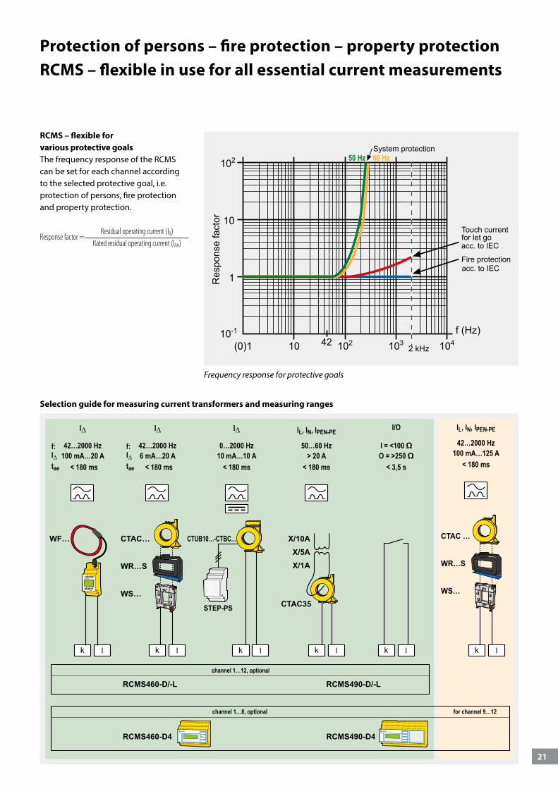
Protection of persons – fire protection – property protectionRCMS – flexible in use for all essential current measurements
RCMS – flexible for various protective goalsThe frequency response of the RCMS can be set for each channel according to the selected protective goal, i.e. protection of persons, fire protection and property protection.
Response factor = Residual operating current (I∆)
Rated residual operating current (I∆n)
Frequency response for protective goals
Selection guide for measuring current transformers and measuring ranges
22
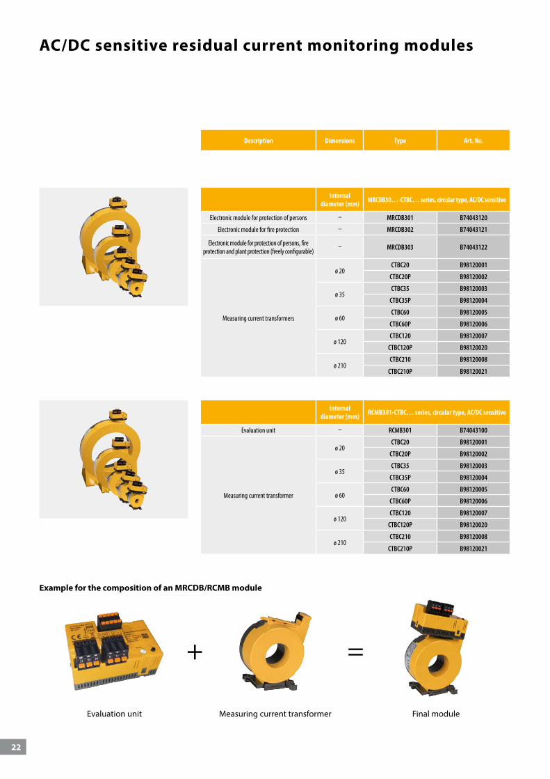
AC/DC sensitive residual current monitoring modules
Description Dimensions Type Art. No.
Internal diameter (mm) MRCDB30…-CTBC… series, circular type, AC/DC sensitive
Electronic module for protection of persons – MRCDB301 B74043120
Electronic module for fire protection – MRCDB302 B74043121
Electronic module for protection of persons, fire protection and plant protection (freely configurable)
– MRCDB303 B74043122
Measuring current transformers
ø 20CTBC20 B98120001
CTBC20P B98120002
ø 35CTBC35 B98120003
CTBC35P B98120004
ø 60CTBC60 B98120005
CTBC60P B98120006
ø 120CTBC120 B98120007
CTBC120P B98120020
ø 210CTBC210 B98120008
CTBC210P B98120021
Internal diameter (mm) RCMB301-CTBC… series, circular type, AC/DC sensitive
Evaluation unit – RCMB301 B74043100
Measuring current transformer
ø 20CTBC20 B98120001
CTBC20P B98120002
ø 35CTBC35 B98120003
CTBC35P B98120004
ø 60CTBC60 B98120005
CTBC60P B98120006
ø 120CTBC120 B98120007
CTBC120P B98120020
ø 210CTBC210 B98120008
CTBC210P B98120021
Example for the composition of an MRCDB/RCMB module
Evaluation unit Measuring current transformer Final module
+ =
23
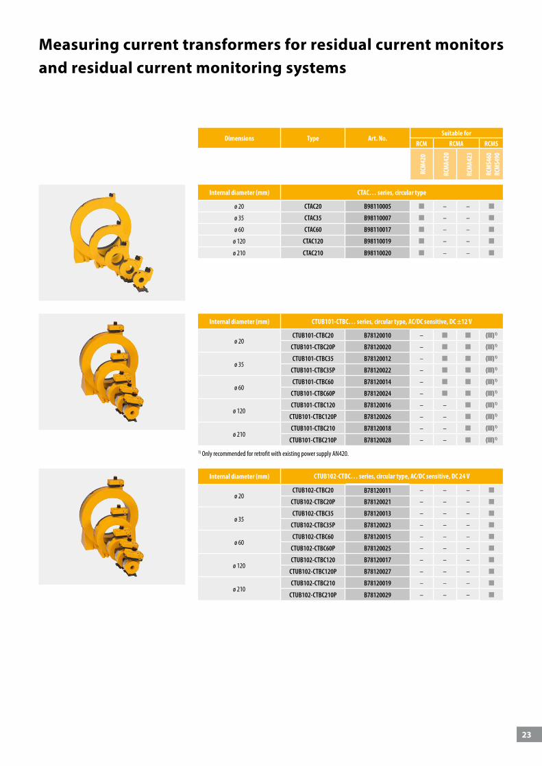
Measuring current transformers for residual current monitors and residual current monitoring systems
Internal diameter (mm) CTAC… series, circular type
ø 20 CTAC20 B98110005 – –
ø 35 CTAC35 B98110007 – –
ø 60 CTAC60 B98110017 – –
ø 120 CTAC120 B98110019 – –
ø 210 CTAC210 B98110020 – –
Dimensions Type Art. No.Suitable for
RCM RCMA RCMS
RCM
420
RCM
A420
RCM
A423
RCM
S460
RC
MS4
90
Internal diameter (mm) CTUB101-CTBC… series, circular type, AC/DC sensitive, DC ±12 V
ø 20CTUB101-CTBC20 B78120010 – ( )1)
CTUB101-CTBC20P B78120020 – ( )1)
ø 35CTUB101-CTBC35 B78120012 – ( )1)
CTUB101-CTBC35P B78120022 – ( )1)
ø 60CTUB101-CTBC60 B78120014 – ( )1)
CTUB101-CTBC60P B78120024 – ( )1)
ø 120CTUB101-CTBC120 B78120016 – – ( )1)
CTUB101-CTBC120P B78120026 – – ( )1)
ø 210CTUB101-CTBC210 B78120018 – – ( )1)
CTUB101-CTBC210P B78120028 – – ( )1)
Internal diameter (mm) CTUB102-CTBC… series, circular type, AC/DC sensitive, DC 24 V
ø 20CTUB102-CTBC20 B78120011 – – –
CTUB102-CTBC20P B78120021 – – –
ø 35CTUB102-CTBC35 B78120013 – – –
CTUB102-CTBC35P B78120023 – – –
ø 60CTUB102-CTBC60 B78120015 – – –
CTUB102-CTBC60P B78120025 – – –
ø 120CTUB102-CTBC120 B78120017 – – –
CTUB102-CTBC120P B78120027 – – –
ø 210CTUB102-CTBC210 B78120019 – – –
CTUB102-CTBC210P B78120029 – – –
1) Only recommended for retrofit with existing power supply AN420.
24
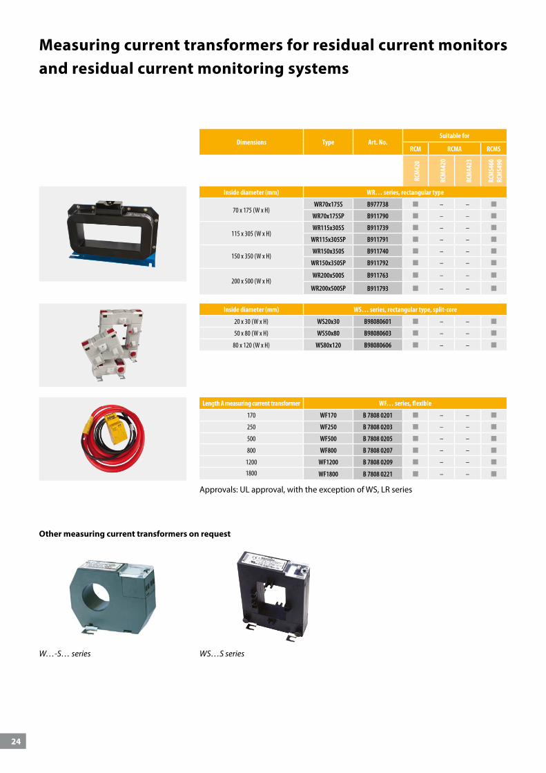
Measuring current transformers for residual current monitors and residual current monitoring systems
Other measuring current transformers on request
W…-S… series WS…S series
Dimensions Type Art. No.Suitable for
RCM RCMA RCMS
RCM
420
RCM
A420
RCM
A423
RCM
S460
RC
MS4
90
Inside diameter (mm) WS… series, rectangular type, split-core
20 x 30 (W x H) WS20x30 B98080601 – –
50 x 80 (W x H) WS50x80 B98080603 – –
80 x 120 (W x H) WS80x120 B98080606 – –
Inside diameter (mm) WR… series, rectangular type
70 x 175 (W x H)WR70x175S B977738 – –
WR70x175SP B911790 – –
115 x 305 (W x H)WR115x305S B911739 – –
WR115x305SP B911791 – –
150 x 350 (W x H)WR150x350S B911740 – –
WR150x350SP B911792 – –
200 x 500 (W x H)WR200x500S B911763 – –
WR200x500SP B911793 – –
Length A measuring current transformer WF… series, flexible
170 WF170 B 7808 0201 – –
250 WF250 B 7808 0203 – –
500 WF500 B 7808 0205 – –
800 WF800 B 7808 0207 – –
1200 WF1200 B 7808 0209 – –
1800 WF1800 B 7808 0221 – –
Approvals: UL approval, with the exception of WS, LR series
25
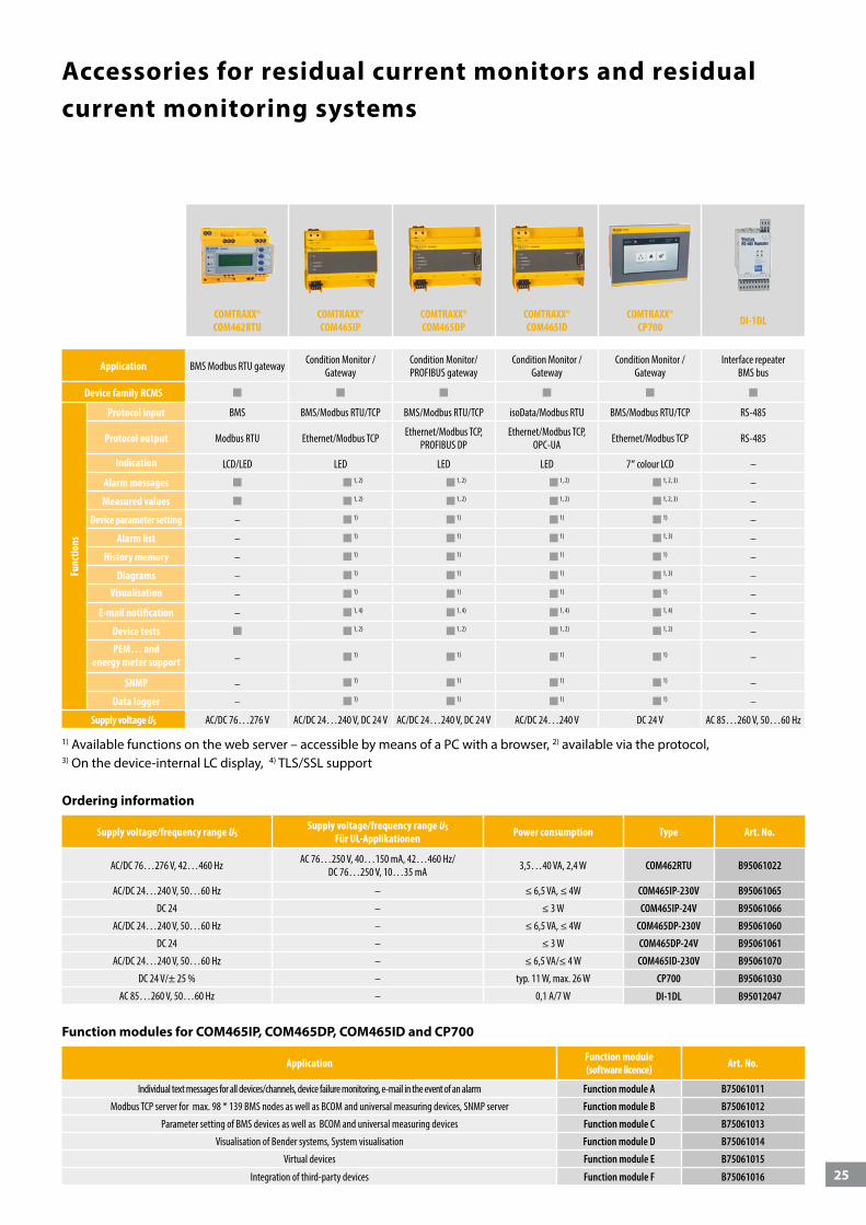
Accessories for residual current monitors and residual current monitoring systems
Ordering information
COMTRAXX® COM462RTU
COMTRAXX® COM465IP
COMTRAXX® COM465DP
COMTRAXX® COM465ID
COMTRAXX® CP700 DI-1DL
Application BMS Modbus RTU gateway Condition Monitor / Gateway
Condition Monitor/ PROFIBUS gateway
Condition Monitor / Gateway
Condition Monitor / Gateway
Interface repeaterBMS bus
Device family RCMS
Func
tions
Protocol input BMS BMS/Modbus RTU/TCP BMS/Modbus RTU/TCP isoData/Modbus RTU BMS/Modbus RTU/TCP RS-485
Protocol output Modbus RTU Ethernet/Modbus TCP Ethernet/Modbus TCP, PROFIBUS DP
Ethernet/Modbus TCP, OPC-UA Ethernet/Modbus TCP RS-485
Indication LCD/LED LED LED LED 7“ colour LCD –
Alarm messages 1, 2) 1, 2) 1, 2) 1, 2, 3) –
Measured values 1, 2) 1, 2) 1, 2) 1, 2, 3) –
Device parameter setting – 1) 1) 1) 1) –
Alarm list – 1) 1) 1) 1, 3) –
History memory – 1) 1) 1) 1) –
Diagrams – 1) 1) 1) 1, 3) –Visualisation – 1) 1) 1) 1) –
E-mail notification – 1, 4) 1, 4) 1, 4) 1, 4) –
Device tests 1, 2) 1, 2) 1, 2) 1, 2) –
PEM… and energy meter support – 1) 1) 1) 1) –
SNMP – 1) 1) 1) 1) –
Data logger – 1) 1) 1) 1) –
Supply voltage US AC/DC 76…276 V AC/DC 24…240 V, DC 24 V AC/DC 24…240 V, DC 24 V AC/DC 24…240 V DC 24 V AC 85…260 V, 50…60 Hz
1) Available functions on the web server – accessible by means of a PC with a browser, 2) available via the protocol, 3) On the device-internal LC display, 4) TLS/SSL support
Function modules for COM465IP, COM465DP, COM465ID and CP700
Application Function module (software licence) Art. No.
Individual text messages for all devices/channels, device failure monitoring, e-mail in the event of an alarm Function module A B75061011
Modbus TCP server for max. 98 * 139 BMS nodes as well as BCOM and universal measuring devices, SNMP server Function module B B75061012
Parameter setting of BMS devices as well as BCOM and universal measuring devices Function module C B75061013
Visualisation of Bender systems, System visualisation Function module D B75061014
Virtual devices Function module E B75061015
Integration of third-party devices Function module F B75061016
Supply voltage/frequency range USSupply voltage/frequency range US
Für UL-Applikationen Power consumption Type Art. No.
AC/DC 76…276 V, 42…460 Hz AC 76…250 V, 40…150 mA, 42…460 Hz/ DC 76…250 V, 10…35 mA 3,5…40 VA, 2,4 W COM462RTU B95061022
AC/DC 24…240 V, 50…60 Hz – ≤ 6,5 VA, ≤ 4W COM465IP-230V B95061065
DC 24 – ≤ 3 W COM465IP-24V B95061066
AC/DC 24…240 V, 50…60 Hz – ≤ 6,5 VA, ≤ 4W COM465DP-230V B95061060
DC 24 – ≤ 3 W COM465DP-24V B95061061
AC/DC 24…240 V, 50…60 Hz – ≤ 6,5 VA/≤ 4 W COM465ID-230V B95061070
DC 24 V/± 25 % – typ. 11 W, max. 26 W CP700 B95061030
AC 85…260 V, 50…60 Hz – 0,1 A/7 W DI-1DL B95012047
26
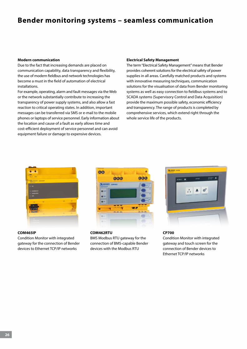
Bender monitoring systems – seamless communication
COM465IPCondition Monitor with integrated gateway for the connection of Bender devices to Ethernet TCP/IP networks
COM462RTUBMS Modbus RTU gateway for the connection of BMS-capable Bender devices with the Modbus RTU
CP700Condition Monitor with integrated gateway and touch screen for the connection of Bender devices to Ethernet TCP/IP networks
Modern communicationDue to the fact that increasing demands are placed on communication capability, data transparency and flexibility, the use of modern fieldbus and network technologies has become a must in the field of automation of electrical installations. For example, operating, alarm and fault messages via the Web or the network substantially contribute to increasing the transparency of power supply systems, and also allow a fast reaction to critical operating states. In addition, important messages can be transferred via SMS or e-mail to the mobile phones or laptops of service personnel. Early information about the location and cause of a fault as early allows time and cost-efficient deployment of service personnel and can avoid equipment failure or damage to expensive devices.
Electrical Safety Management The term “Electrical Safety Management” means that Bender provides coherent solutions for the electrical safety of power supplies in all areas. Carefully matched products and systems with innovative measuring techniques, communication solutions for the visualisation of data from Bender monitoring systems as well as easy connection to fieldbus systems and to SCADA systems (Supervisory Control and Data Acquisition) provide the maximum possible safety, economic efficiency and transparency. The range of products is completed by comprehensive services, which extend right through the whole service life of the products.

27
Is your system still state of the art?
Even the most modern electrical systems cannot escape the marks of time. Whether diminishing operational reliability, changed legal stipulations or increasing energy costs: Upgrading to the respective current state of the art is indispensable. Products for monitoring energy quality and fault search are typically retrofitted.
Risk assessment according to operating safety regulations: Does your presently installed monitoring equipment recognise symmetrical and asymmetrical insulation faults?
Symmetrical and asymmetrical insulation faults present a high risk potential. Bender insulation monitoring devices continuously monitor your systems, insulation faults are captured and reported. Bender insulation monitoring devices comply with IEC 61557-8.
We will check your electrical installations and provide you with recommendations on how to proceed further.
Bender delivers flexible solutions for retrofit projects
Modern monitoring methods can be integrated in older installations as well – also during ongoing operations. Retrofitting is possible via devices such as divisible transformers, whereby the transformers are not even required to be shut down nor must cable installations be disconnected.
Successor devices from Bender can conveniently replace older installations. Long-term availability is thus guaranteed.
Retrofit

28
POWERSCOUT®Find out today what won't happen tomorrow
Moisture, deterioration, dirt, mechanical damage or faults due to the impact of current, voltage and temperature cause malfunctions in every electrical installation. The web-based soft-ware solution POWERSCOUT® helps you detect malfunctions at an early stage and eliminate the causes in an economically rea-sonable way. This guarantees high installation and operational safety and reduces costs.
POWERSCOUT® is your tool: It can be precisely adjusted to yoursystem and your monitoring requirements during setup. Easy, clear and fast. Open the browser, log in, select the required measuring devices and measured quantities, done.
POWERSCOUT®: The web-based software solution for analysis, predictive maintenance and report.
29
Analysis
Continuously recording insula-tion values
Recognising connections and optimising maintenance
Cross-system evaluation possibilities
Access from any place
Supporting investment decisions
Predictive maintenance
Higher availability
Continuous monitoring
Early detection of gradually developing insulation faults
Early detection and reporting of short-time insulation degrada-tion
Less costs incurred due to unex-pected malfunctions and shut-downs
Reports
Historical comparisons
Safe storage of measured values
Event and alarm statistics
Analysis – as individual as your system– as simple as possiblePredictive maintenance prevents downtimes, reduces costs and staff deployment. POWERSCOUT® informs you about the condition of your electrical installation at all times, since the meaningful visualisations with flexible dashboards can be retrieved via any display device: smartphone, laptop, computer. On request, POWERSCOUT® sends you graphically processed reports at specified intervals.
Continuous monitoring instead of random tests
Manual data acquisition is time consuming, error prone and only provides random sampling results. POWERSCOUT® gives you an insight into the entire data of your installation at any time, since all measured values are automatically and continuously saved. Your data is stored reliably and remains available for years.
Basis for periodic verification
The automated POWERSCOUT® report on residual currents forms the basis for measuring without switch-off by means of periodic verification. In order to maintain the correct status for electrical installations and stationary electrical equipment, periodic verification must be carried out.
This can be ensured, for example, by means of continuous monitoring of the installation carried out by qualified personnel. In this case, it would be smart to rely on continuous monitoring with multi-channel residual current monitoring systems (RCMS) and an evaluation (CP700) adapted to the system. The automatic POWERSCOUT® reports based on this monitoring enable the qualified person in charge to adjust the time limits for the insulation test within the context of periodic verification.

30
Planning & concept
& modernisation
Operation & maintenance
Extension
Installation & commissioning
Device selection & project planning
Bender serviceWORLDWIDE
Support during all stagesComprehensive service for your installation: remote, by phone, on site
Competent service for maximum safety and high availability of
your installation
From planning to modernisation – Our extensive know-how is at your disposal during all project phases.
Furthermore, with our first-class service we guarantee maximum safety for your electrical installations. We offer services ranging from support over telephone to repairs and on-site service – with modern measuring devices and competent employees.
Secure yourself:
High availability of your installation thanks to fast reaction to fault messages
Increased profitability of your capital expenditure (CapEx) via optimised maintenance processes
Targeted operating expenditure (OpEx) due to less downtimes and shorter service visits
Support for your prospective system monitoring and regular tests of your system/power quality/monitoring devices
Automatic control, analysis, correction, new settings/updates
Competent assistance with setting changes and updates
Bender Remote Assist Bender Remote Assist offers you support via remote access, high-quality service and advice for your challenging task consisting in ensuring consistent high safety in your systems.
Many service visits, fault clearance but also analyses and controls can be carried out remotely – without the expenses of time and money that an on-site visit of a technician implies.
This fast, efficient help and advice by our expert network allows the highest possible availability of your system.
Fault location – made easyWith portable fault location systems, existing insulation faults can be quickly located. They are the best alternative if no stationary equip-ment for insulation fault location is available.

31
Bender. So that your world is safer.
Our world is networked on a global scale; it is digital, mobile and highly automated – whether in manufacturing industry, inside or outside buildings, in operating theatres and power stations, in trains, underwater or underground: it never stands still and it is more dependent than ever on a reliable and, above all, safe electrical power supply.
And exactly that is our mission: we make electricity safe. Using our technologies we ensure that electricity is permanently available and guarantee faultless protection against the hazards of electric shock. We protect buil-dings, plants and machinery and therefore your investments and plans. But what we primarily protect are the lives of the people who are involved with electricity.
www.bender.deData centres
Ships and ports
HealthcareMechanical and plant engineering
Mining
Railway
Puplic power supply network
Oil, gas
eMobility
Mobile power generationRenewable energy

Photos: iStock (© William Fawcett), Adobe Stock (© Mihai Simonia, © Paolo Sartorio, © Gabriele Rohde, © Rainer Fuhrmann), Fotolia (© Ramona Heim, © elgris, © tomas), 123RF (© Gerard Koudenburg, © Volker Rauch, © stefan 77), Thinkstock (© monkeybusinessimages), Bender archives. 21
23en
/ 03
.201
9 / p
df /
© B
ende
r Gm
bH &
Co.
KG
, Ger
man
y –
subj
ect t
o ch
ange
! The
spe
cifie
d st
anda
rds
take
into
acc
ount
the
vers
ion
that
was
val
id a
t the
tim
e of
prin
ting.
BENDER Group
Bender GmbH & Co. KGP.O. Box 1161 • 35301 Grünberg • GermanyLondorfer Straße 65 • 35305 Grünberg • GermanyTel.: +49 6401 807-0 • Fax: +49 6401 807-259E-mail: [email protected] • www.bender.de