Embed Size (px)
Citation preview
Production Test API Reference Manual
JN-RM-2027
Revision 1.6
20-Dec-2012

Production Test API Reference Manual
2 © NXP Laboratories UK 2012 JN-RM-2027 v1.6
Production Test API Reference Manual
JN-RM-2027 v1.6 © NXP Laboratories UK 2012 3
Contents About this Manual 5
Organisation 5 Conventions 5 Acronyms and Abbreviations 5 Related Documents 5 Trademarks 6
1 Introduction 7 1.1 Purpose of API 7 1.2 Supplied Software 7 1.3 Hardware Requirements 8
2 API Initialisation 9 u32JPT_Init 10
3 Radio Management 11 bJPT_RadioInit 12 vJPT_RadioDeInit 13 bJPT_RadioSetChannel 14 u8JPT_RadioGetChannel 15 vJPT_RadioSetPower 16 u8JPT_RadioGetPower 17 vJPT_RadioSetPowerFine (JN5139 only) 18 u8JPT_RadioGetPowerFine (JN5139 only) 19 u32JPT_RadioModesAvailable 20
4 Energy Detection 21 bJPT_CCA 22 u8JPT_EnergyDetect 23 u8JPT_FineTuneEnergyDetect 24 i16JPT_ConvertEnergyTodBm 25
5 Power and Oscillator Tests 27 vJPT_TxPowerTest 28 vJPT_XtalOscillatorTest 29
6 Module PER Tests 31 vJPT_MTPT_MasterStart 32 vJPT_MTPT_MasterTxPacket 33 vJPT_MTPT_MasterStop 34 vJPT_MTPT_SlaveStart 35 vJPT_MTPT_SlavePoll 36 vJPT_MTPT_SlaveStop 37
7 Trigger Packet Tests 39 vJPT_TPT_Start 40 u32JPT_TPT_WaitPacket 41 vJPT_TPT_Stop 42
8 Site Survey PER Tests 43 vJPT_SSPT_MasterInit 45 bJPT_SSPT_MasterSetState 46 vJPT_SSPT_MasterGetState 47 vJPT_SSPT_SlaveInit 48
Production Test API Reference Manual
4 © NXP Laboratories UK 2012 JN-RM-2027 v1.6
vJPT_SSPT_SlaveGetState 49
9 Packet Receive/Transmit Tests 51 bJPT_PacketRx 52 vJPT_PacketTx 53
Appendices 55 A Structures 55 B Channel Numbering 58
Production Test API Reference Manual
JN-RM-2027 v1.6 © NXP Laboratories UK 2012 5
About this Manual This manual describes the functions of the NXP Production Test API (Application Programming Interface) for the JN51xx wireless microcontrollers.
Organisation This manual consists of 9 chapters and 2 appendices as follows:
• Chapter 1 introduces the Production Test API.
• Chapter 2 details the function used to initialise the API.
• Chapter 3 details the functions used to manipulate the radio state of the module under test.
• Chapter 4 details the functions used to perform and interpret the results of an energy level test.
• Chapter 5 details the functions used to test the module’s transmission power and crystal oscillator frequency.
• Chapter 6 details the functions used to perform module PER tests.
• Chapter 7 details the functions used to perform trigger packet tests.
• Chapter 8 details the functions used to perform site survey PER tests.
• Chapter 9 details the functions used to perform packet receive/transmit tests.
• Appendix A details the data structures used by the API.
• Appendix B gives the frequency channel numbering scheme.
Conventions Files, folders, functions and parameter types are represented in bold type.
Function parameters are represented in italics type.
Code fragments are represented in the Courier typeface.
Acronyms and Abbreviations API Application Programming Interface
PER Packet Error Rate
Related Documents [1] IEEE 802.15.4 Standard – 2003 (SS95127)
[2] JN514x Integrated Peripherals API User Guide (JN-UG-3066)
[3] JN516x Integrated Peripherals API User Guide (JN-UG-3087)

Production Test API Reference Manual
6 © NXP Laboratories UK 2012 JN-RM-2027 v1.6
Trademarks All trademarks are the property of their respective owners.
Production Test API Reference Manual
JN-RM-2027 v1.6 © NXP Laboratories UK 2012 7
1 Introduction This chapter introduces the Production Test Application Programming Interface (API) for the NXP JN51xx wireless microcontrollers.
1.1 Purpose of API The Production Test API allows code to be developed to carry out certain tests during the design and production of network products based on the NXP JN51xx wireless microcontrollers. The tests are designed to help ensure a product meets the required operating specifications.
The tests that you can perform with the API include the following:
• Measure the energy level in a particular radio frequency channel
• Measure the transmission power of a module
• Perform transmission/reception tests
• Measure the frequency of a module’s crystal oscillator
• Measure the PER in data transfers from one module to another
• Perform site survey tests (such as range tests)
! Caution: Software developed using this API cannot be used in conjunction with the IEEE 802.15.4, JenNet-IP or ZigBee PRO stack.
1.2 Supplied Software The Production Test API is supplied in the following header and library files (separate library files are supplied for the JN514x and JN516x chip families):
JPT.h libJPT_JN514x.a libJPT_JN516x.a
Note: You will also need to link your code with the JN514x or JN516x Integrated Peripherals API, as appropriate for your target chip.

Production Test API Reference Manual
8 © NXP Laboratories UK 2012 JN-RM-2027 v1.6
1.3 Hardware Requirements The hardware under test is referred to as a module – this is any board or device based on the NXP JN51xx wireless microcontrollers.
Some of the tests (the PER tests) involve using two modules: a master and a slave. These modules may be identical, apart from the software that runs on them. For the module PER tests, they must be connected via their UARTs, as well as via the RF link.
In some of the tests, you will also need additional hardware, such as a frequency counter or an arbitrary waveform generator (Arb).
The Arb is used in trigger packet tests (see Chapter 7). The recommended model is the Agilent E4433B (250 kHz – 4 GHz) with the following options installed:
• Option UND: Dual arbitrary waveform generator
• Option UN8: I/Q baseband generator
For more details on the Arb, refer to the Agilent web site: http://www.agilent.com/
Production Test API Reference Manual
JN-RM-2027 v1.6 © NXP Laboratories UK 2012 9
2 API Initialisation This chapter details the function that you must call to initialise the Production Test API.
The function is listed below, along with its page reference.
Function Page u32JPT_Init 7
Production Test API Reference Manual
10 © NXP Laboratories UK 2012 JN-RM-2027 v1.6
u32JPT_Init
PUBLIC uint32 u32JPT_Init(void);
Description This function initialises the Production Test API. It must be called before all other functions of the API.
Parameters None
Returns Version number of the API, or zero if the API is running on an unsupported chip
Production Test API Reference Manual
JN-RM-2027 v1.6 © NXP Laboratories UK 2012 11
3 Radio Management This chapter details the functions concerned with managing the radio part of the module under test.
The functions are listed below, along with their page references.
Function Page bJPT_RadioInit 12 vJPT_RadioDeInit 13 bJPT_RadioSetChannel 14 u8JPT_RadioGetChannel 15 vJPT_RadioSetPower 16 u8JPT_RadioGetPower 17 vJPT_RadioSetPowerFine 18 u8JPT_RadioGetPowerFine 19
Production Test API Reference Manual
12 © NXP Laboratories UK 2012 JN-RM-2027 v1.6
bJPT_RadioInit
PUBLIC bool_t bJPT_RadioInit(uint32 u32RadioMode);
Description This function enables the radio part of the wireless microcontroller. You must first call this function in order to use the module to transmit and/or receive over the radio. As part of this function, you must specify the radio operating mode.
Parameters u32RadioMode Sets the radio operating mode:
E_JPT_MODE_HIPOWER - High-power mode for JN514x and JN516x. Also used for JN516x-M05 ETSI modules
E_JPT_MODE_BOOST - Boost mode (JN513x only) E_JPT_MODE_LOPOWER - Normal mode E_JPT_MODE_0DBM - 0dBm mode (JN514x only) E_JPT_MODE_ETSI - ETSI mode (JN514x only)
Returns TRUE: Radio initialised successfully FALSE: An error occurred during radio initialisation
Note: E_JPT_MODE_HIPOWER is used for both JN516x-M06 high-power and JN516x-M05 ETSI modules.

Production Test API Reference Manual
JN-RM-2027 v1.6 © NXP Laboratories UK 2012 13
vJPT_RadioDeInit
PUBLIC void vJPT_RadioDeInit(void);
Description This function disables the radio part of the wireless microcontroller (if it has been previously enabled using the function vJPT_RadioInit()).
Parameters None
Returns None
Production Test API Reference Manual
14 © NXP Laboratories UK 2012 JN-RM-2027 v1.6
bJPT_RadioSetChannel
PUBLIC bool_t bJPT_RadioSetChannel(uint8 u8Channel);
Description This function is used to select the radio channel in which the module will operate.
Parameters u8channel Channel number of radio frequency channel in which
module will operate (integer value in the range 11 to 26 – refer to the table in Appendix B on page 58).
Returns TRUE: Channel change successful FALSE: Channel change failed
Production Test API Reference Manual
JN-RM-2027 v1.6 © NXP Laboratories UK 2012 15
u8JPT_RadioGetChannel
PUBLIC uint8 u8JPT_RadioGetChannel(void);
Description This function is used to obtain the radio channel in which the module is operating.
Parameters None
Returns Integer value in the range 11 to 26
Production Test API Reference Manual
16 © NXP Laboratories UK 2012 JN-RM-2027 v1.6
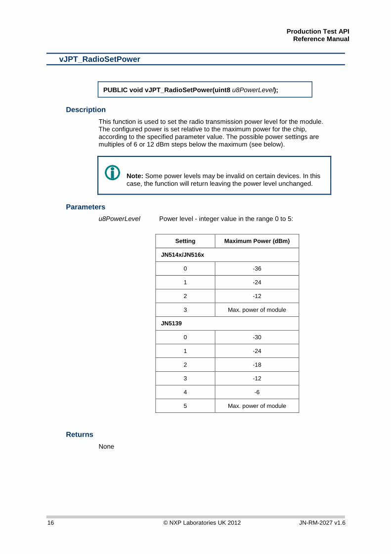
vJPT_RadioSetPower
PUBLIC void vJPT_RadioSetPower(uint8 u8PowerLevel);
Description This function is used to set the radio transmission power level for the module. The configured power is set relative to the maximum power for the chip, according to the specified parameter value. The possible power settings are multiples of 6 or 12 dBm steps below the maximum (see below).
Note: Some power levels may be invalid on certain devices. In this case, the function will return leaving the power level unchanged.
Parameters u8PowerLevel Power level - integer value in the range 0 to 5:
Setting Maximum Power (dBm)
JN514x/JN516x
0 -36
1 -24
2 -12
3 Max. power of module
JN5139
0 -30
1 -24
2 -18
3 -12
4 -6
5 Max. power of module
Returns None

Production Test API Reference Manual
JN-RM-2027 v1.6 © NXP Laboratories UK 2012 17
u8JPT_RadioGetPower
PUBLIC uint8 u8JPT_RadioGetPower(void);
Description This function is used to obtain the power level at which the module is operating.
Parameters None
Returns Integer value in the range 0 to 5

Production Test API Reference Manual
18 © NXP Laboratories UK 2012 JN-RM-2027 v1.6
vJPT_RadioSetPowerFine (JN5139 only)
PUBLIC void vJPT_RadioSetPowerFine(uint8 u8PowerLevel);
Description This function is used to set the radio transmission power level for a JN5139 module in small steps. The configured power is set relative to the maximum power for the chip.
Note: Some power levels may be invalid on certain devices. In this case, the function will return leaving the power level unchanged.
Parameters u8PowerLevel Power level - integer value in the range 0 to 47
Returns None
Production Test API Reference Manual
JN-RM-2027 v1.6 © NXP Laboratories UK 2012 19
u8JPT_RadioGetPowerFine (JN5139 only)
PUBLIC uint8 u8JPT_RadioGetPowerFine(void);
Description This function is used to obtain the fine-adjust power level at which a JN5139 module is operating.
Parameters None
Returns Integer value in the range 0 to 47
Production Test API Reference Manual
20 © NXP Laboratories UK 2012 JN-RM-2027 v1.6
u32JPT_RadioModesAvailable
PUBLIC uint32 u32JPT_RadioModesAvailable(void);
Description This function is used to obtain the radio modes supported by this device.
Parameters None
Returns 32-bit bitmap of radio modes - this can be ANDed with the defined modes (e.g. E_JPT_MODE_LOPOWER) to identify whether a mode is supported. Example: u32JPT_RadioModes = u32JPT_RadioModesAvailable(); /* Get the Modes supported by this device */ if (u32JPT_RadioModes & (1<<E_JPT_MODE_HIPOWER)){ vPrintf( "High power mode supported\n”); }

Production Test API Reference Manual
JN-RM-2027 v1.6 © NXP Laboratories UK 2012 21
4 Energy Detection This chapter details the functions concerned with energy detection in radio channels.
The functions are listed below, along with their page references.
Function Page bJPT_CCA 22 u8JPT_EnergyDetect 23 u8JPT_FineTuneEnergyDetect 24 i16JPT_ConvertEnergyTodBm 25
Note: For an illustration of the use of these functions in code, refer to the Application Note Site Survey Tool (JN-AN-1014 for JN514x, JN-AN-1094 for JN516x).
Production Test API Reference Manual
22 © NXP Laboratories UK 2012 JN-RM-2027 v1.6
bJPT_CCA
PUBLIC bool_t bJPT_CCA(uint8 u8Channel, uint8 u8Mode, uint8 u8Threshold);
Description This function is used to perform a clear channel assessment in the specified channel.
Parameters u8Channel Channel number of the radio frequency channel for the
test (integer value in the range 11 to 26 – refer to the table in Appendix B on page 58)
u8Mode Clear channel assessment mode, one of: E_JPT_CCA_MODE_ENERGY E_JPT_CCA_MODE_CARRIER E_JPT_CCA_MODE_CARRIER_OR_ENERGY E_JPT_CCA_MODE_CARRIER_AND_ENERGY u8Threshold Energy detect (integer value in the range 0 to 255)
Returns TRUE: Channel busy FALSE: Channel clear

Production Test API Reference Manual
JN-RM-2027 v1.6 © NXP Laboratories UK 2012 23
u8JPT_EnergyDetect
PUBLIC uint8 u8JPT_EnergyDetect(uint8 u8Channel, uint32 u32Samples);
Description This function is used to perform an energy level test in the specified channel for a duration corresponding to the specified number of samples. The function finds the peak energy level.
Parameters u8Channel Channel number of the radio frequency channel for the
test (integer value in the range 11 to 26 – refer to the table in Appendix B on page 58)
u32Samples Number of consecutive samples in energy level test (integer value in the range 0 to 232 – 1)
Returns Integer value in the range 0 to 255, corresponding to peak energy level detected over specified number of samples
Production Test API Reference Manual
24 © NXP Laboratories UK 2012 JN-RM-2027 v1.6
u8JPT_FineTuneEnergyDetect
PUBLIC uint8 u8JPT_FineTuneEnergyDetect(uint32 u32Frequency, uint32 u32Samples);
Description This function is used to perform an energy level test in the specified channel for a duration corresponding to the specified number of samples. The function finds the peak energy level.
Parameters u32Frequency Frequency in MHz on which to perform the measurement
(integer value in the range 2350 to 2550) u32Samples Number of consecutive samples in energy level test
(integer value in the range 0 to 232 – 1)
Returns Integer value in the range 0 to 255, corresponding to peak energy level detected over specified number of samples.
Production Test API Reference Manual
JN-RM-2027 v1.6 © NXP Laboratories UK 2012 25
i16JPT_ConvertEnergyTodBm
PUBLIC int16 i16JPT_ConvertEnergyTodBm(uint8 u8Energy);
Description This function is used to convert the specified energy level (an integer value in the range 0 to 255) into meaningful units: dBm (decibels referenced to 1 mW). For example, you can use this function to interpret the result of an energy level test performed using the function u8JPT_EnergyDetect().
Parameters u8Energy Energy level to be converted (integer value in the range
0 to 255)
Returns Energy level expressed in dBm. The range of possible output values is: –11 dBm to –98 dBm, with 2 dBm step accuracy

Production Test API Reference Manual
26 © NXP Laboratories UK 2012 JN-RM-2027 v1.6
Production Test API Reference Manual
JN-RM-2027 v1.6 © NXP Laboratories UK 2012 27
5 Power and Oscillator Tests This chapter details the functions concerned with testing the transmission power and crystal oscillator frequency of a module.
The functions are listed below, along with their page references.
Function Page vJPT_TxPowerTest 28 vJPT_XtalOscillatorTest 29
Production Test API Reference Manual
28 © NXP Laboratories UK 2012 JN-RM-2027 v1.6
vJPT_TxPowerTest
PUBLIC void vJPT_TxPowerTest(uint32 u32Mode);
Description This function is used to put the module in or out of a state of continuous transmission. You must specify the required transmission mode, one of: Continuous Wave
Continuous Modulated Pseudo-Random Binary Sequence (PRBS) Stop
This allows a transmission power test to be performed.
Parameters u32mode The transmission mode of the module: E_JPT_TXPT_RUN_CW - Continuous Wave mode E_JPT_TXPT_RUN_PRBS - PRBS mode E_JPT_TXPT_STOP - Stop mode
Returns None
Production Test API Reference Manual
JN-RM-2027 v1.6 © NXP Laboratories UK 2012 29
vJPT_XtalOscillatorTest
PUBLIC void vJPT_XtalOscillatorTest(uint32 u32Mode);
Description This function is used to enable or disable output of the module’s crystal oscillator signal in order to allow its frequency to be checked by an external device. The signal is a square wave output on the DIO10 pin, when output is enabled. A frequency counter can be connected to this pin in order to measure the oscillator’s frequency. In order to enable oscillator output using this function, you first need to enable the radio part of the JN51xx chip using the function vJPT_RadioInit(), described on page 12.
Parameters u32mode Enables or disables oscillator output: E_JPT_XOT_DIO10 Enable output on DIO10 pin E_JPT_XOT_STOP Disable output
Returns None

Production Test API Reference Manual
30 © NXP Laboratories UK 2012 JN-RM-2027 v1.6
Production Test API Reference Manual
JN-RM-2027 v1.6 © NXP Laboratories UK 2012 31
6 Module PER Tests This chapter details the functions concerned with module PER (Packet Error Rate) tests in a production environment.
The functions are listed below, along with their page references.
Function Page vJPT_MTPT_MasterStart 32 vJPT_MTPT_MasterTxPacket 33 vJPT_MTPT_MasterStop 34 vJPT_MTPT_SlaveStart 35 vJPT_MTPT_SlavePoll 36 vJPT_MTPT_SlaveStop 37
Note: For an illustration of the use of these functions in code, refer to the appropriate “Customer Module Evaluation Tool” Application Note: JN-AN-1132 or JN-AN-1172.
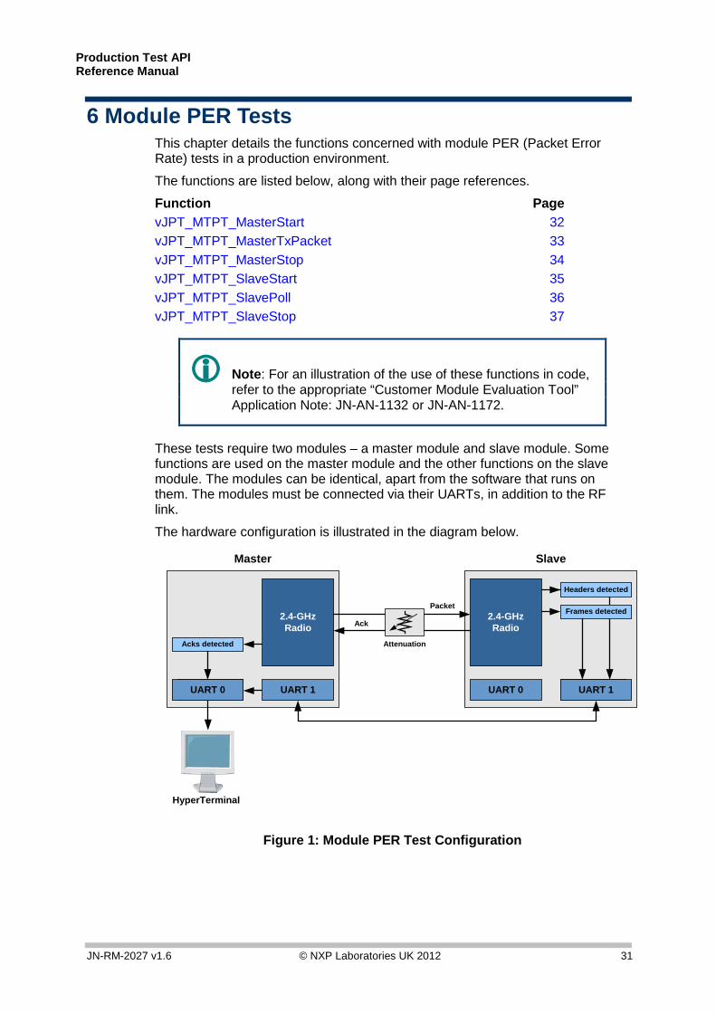
These tests require two modules – a master module and slave module. Some functions are used on the master module and the other functions on the slave module. The modules can be identical, apart from the software that runs on them. The modules must be connected via their UARTs, in addition to the RF link.
The hardware configuration is illustrated in the diagram below.
Slave
2.4-GHzRadio
UART 1
Headers detected
Frames detected
UART 1UART 0
Master
2.4-GHzRadio
UART 1
Acks detected
UART 0 UART 1
Packet
Ack
Attenuation
HyperTerminal
Figure 1: Module PER Test Configuration
Production Test API Reference Manual
32 © NXP Laboratories UK 2012 JN-RM-2027 v1.6
vJPT_MTPT_MasterStart
PUBLIC void vJPT_MTPT_MasterStart(uint8 u8PayloadLength);
Description This function is used to start the master module in order to perform a PER test.
Parameters u8PayloadLength Length of the payload used in the test (integer value in
the range 0 to 100)
Returns None

Production Test API Reference Manual
JN-RM-2027 v1.6 © NXP Laboratories UK 2012 33
vJPT_MTPT_MasterTxPacket
PUBLIC void vJPT_MTPT_MasterTxPacket(uint32 *pu32Acks);
Description This function is used to instruct the master module to transmit a data packet to the slave module. If the transmitted packet is received by the slave, an acknowledgement will be sent by the slave. If an acknowledgement is received by the master, this function increments a user-defined variable giving the running total number of acknowledgements received from the slave.
Parameters *pu32Acks Pointer to user-defined variable of total number of
acknowledgements received from the slave so far.
Returns None
Production Test API Reference Manual
34 © NXP Laboratories UK 2012 JN-RM-2027 v1.6
vJPT_MTPT_MasterStop
PUBLIC void vJPT_MTPT_MasterStop(void);
Description This function is used to stop the master module, following a PER test.
Parameters None
Returns None
Production Test API Reference Manual
JN-RM-2027 v1.6 © NXP Laboratories UK 2012 35
vJPT_MTPT_SlaveStart
PUBLIC void vJPT_MTPT_SlaveStart(void);
Description This function is used to start the slave module in order to perform a PER test.
Parameters None
Returns None
Production Test API Reference Manual
36 © NXP Laboratories UK 2012 JN-RM-2027 v1.6
vJPT_MTPT_SlavePoll
PUBLIC void vJPT_MTPT_SlavePoll(uint32 *pu32HeadersSeen, uint32 *pu32FramesSeen, uint32 *pu32ErrorsSeen);
Description This function is used to make the slave module poll its incoming message queue for data packets. If a packet is retrieved from the queue, the function updates two user-defined variables, one giving the running total number of packet headers detected and the other giving the running total number of data frames detected.
Parameters *pu32HeadersSeen Pointer to user-defined variable of total number of
headers detected so far *pu32FramesSeen Pointer to user-defined variable of total number of
frames detected so far *pu32ErrorsSeen Pointer to user-defined variable of total number of
frames, so far, with errors detected
Returns None
Production Test API Reference Manual
JN-RM-2027 v1.6 © NXP Laboratories UK 2012 37
vJPT_MTPT_SlaveStop
PUBLIC void vJPT_MTPT_SlaveStop(void);
Description This function is used to stop the slave module, following a PER test.
Parameters None
Returns None

Production Test API Reference Manual
38 © NXP Laboratories UK 2012 JN-RM-2027 v1.6
Production Test API Reference Manual
JN-RM-2027 v1.6 © NXP Laboratories UK 2012 39
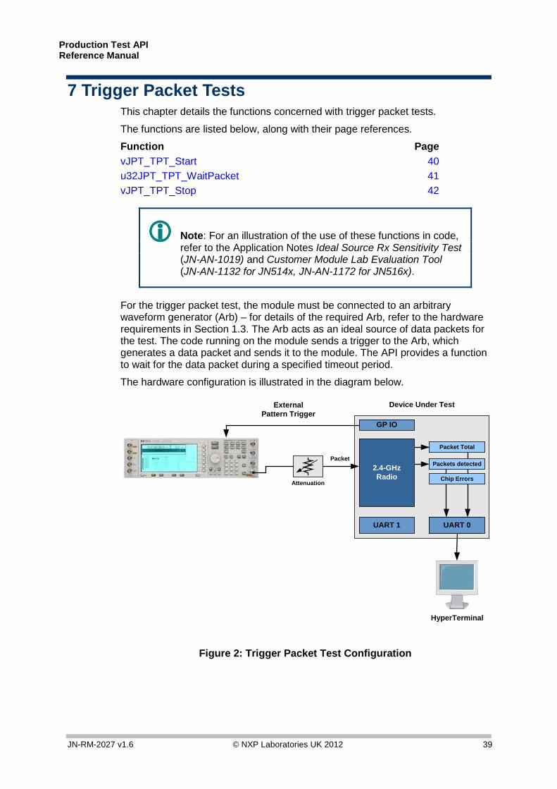
7 Trigger Packet Tests This chapter details the functions concerned with trigger packet tests.
The functions are listed below, along with their page references.
Function Page vJPT_TPT_Start 40 u32JPT_TPT_WaitPacket 41 vJPT_TPT_Stop 42
Note: For an illustration of the use of these functions in code, refer to the Application Notes Ideal Source Rx Sensitivity Test (JN-AN-1019) and Customer Module Lab Evaluation Tool (JN-AN-1132 for JN514x, JN-AN-1172 for JN516x).
For the trigger packet test, the module must be connected to an arbitrary waveform generator (Arb) – for details of the required Arb, refer to the hardware requirements in Section 1.3. The Arb acts as an ideal source of data packets for the test. The code running on the module sends a trigger to the Arb, which generates a data packet and sends it to the module. The API provides a function to wait for the data packet during a specified timeout period.
The hardware configuration is illustrated in the diagram below.
Device Under Test
2.4-GHzRadio
UART 1
Packet Total
Packets detected
UART 0UART 1
Packet
Attenuation
HyperTerminal
Chip Errors
GP IO
ExternalPattern Trigger
Figure 2: Trigger Packet Test Configuration
Production Test API Reference Manual
40 © NXP Laboratories UK 2012 JN-RM-2027 v1.6
vJPT_TPT_Start
PUBLIC void vJPT_TPT_Start(void);
Description This function is used to start a trigger packet test.
Parameters None
Returns None
Production Test API Reference Manual
JN-RM-2027 v1.6 © NXP Laboratories UK 2012 41
u32JPT_TPT_WaitPacket
PUBLIC uint32 u32JPT_TPT_WaitPacket(uint32 u32Timeout, uint32 *pu32Total, uint32 *pu32Seen, uint32 *pu32ChipErrors);
Description This function is used to wait for a data packet sent from an arbitrary waveform generator (Arb) connected to the module (where the generation of this packet has been triggered by the code running on the module). A timeout period is specified corresponding to the maximum duration of the wait. User-defined variables are updated giving statistics on the success of the trigger tests so far. The function returns the value of the timeout counter when the packet was received. In order to use this function, your code must produce triggers to the Arb, and must set up and initialise user-defined variables for the statistics that are updated by this function (see below).
Parameters u32Timeout Timeout period (in ms) for which function will wait for
packet *pu32Total Pointer to user-defined variable of total number of times
the function has been called so far (corresponding to the number of triggers)
*pu32Seen Pointer to user-defined variable of number of packets received so far
*pu32ChipErrors Pointer to user-defined variable of number of chip sequence errors so far
Returns Value of timeout counter when packet was received
Production Test API Reference Manual
42 © NXP Laboratories UK 2012 JN-RM-2027 v1.6
vJPT_TPT_Stop
PUBLIC void vJPT_TPT_Stop(void);
Description This function is used to stop a trigger packet test.
Parameters None
Returns None
Production Test API Reference Manual
JN-RM-2027 v1.6 © NXP Laboratories UK 2012 43
8 Site Survey PER Tests This chapter details the functions concerned with site survey PER (Packet Error Rate) tests. These are tests conducted on a network site – range tests, for example.
The functions are listed below, along with their page references.
Function Page vJPT_SSPT_MasterInit 45 bJPT_SSPT_MasterSetState 46 vJPT_SSPT_MasterGetState 47 vJPT_SSPT_SlaveInit 48 vJPT_SSPT_SlaveGetState 49
Note: For an illustration of the use of these functions in code, refer to the Application Note Packet Error Rate Testing (JN-AN-1006 for JN514x, JN-AN-1175 for JN516x).
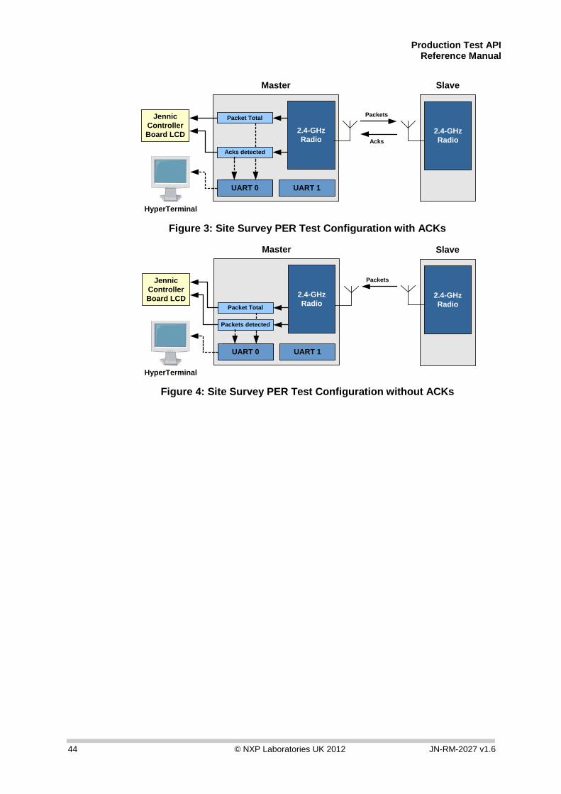
These tests require two modules – a master module and slave module. Some functions are used on the master module and the other functions on the slave module. The modules can be identical, apart from the software that runs on them. For site survey tests, the modules only communicate via the RF link.
The hardware configurations for tests without and without acknowledgement are illustrated in the diagrams below.
Production Test API Reference Manual
44 © NXP Laboratories UK 2012 JN-RM-2027 v1.6
Master
2.4-GHzRadio
UART 1
Acks detected
UART 0 UART 1
HyperTerminal
Packet TotalJennicControllerBoard LCD
Packets
Acks
Slave
2.4-GHzRadio
Figure 3: Site Survey PER Test Configuration with ACKs
Master
2.4-GHzRadio
UART 1
Packets detected
UART 0 UART 1
HyperTerminal
Packet Total
JennicControllerBoard LCD
Packets
Slave
2.4-GHzRadio
Figure 4: Site Survey PER Test Configuration without ACKs

Production Test API Reference Manual
JN-RM-2027 v1.6 © NXP Laboratories UK 2012 45
vJPT_SSPT_MasterInit
PUBLIC void vJPT_SSPT_MasterInit(void);
Description This function initialises the master for the site survey PER tests.
Parameters None
Returns None
Production Test API Reference Manual
46 © NXP Laboratories UK 2012 JN-RM-2027 v1.6
bJPT_SSPT_MasterSetState
PUBLIC bool_t bJPT_SSPT_MasterSetState( tsJPT_SSPT_MasterState *psState);
Description This function allows the running state of the master to be changed according to the parameter values in the specified structure.
Parameters *psState Pointer to structure containing the parameters for the
master – the structure is of the type tsJPT_SSPT_MasterState, detailed in Appendix A, starting on page 55
Returns TRUE: Running state of master successfully changed FALSE: Unable to change running state of master
Production Test API Reference Manual
JN-RM-2027 v1.6 © NXP Laboratories UK 2012 47
vJPT_SSPT_MasterGetState
PUBLIC void vJPT_SSPT_MasterGetState( tsJPT_SSPT_MasterState *psState);
Description This function can be used to obtain the state of the master. The master state is reported in a structure (see below).
Parameters *psState Pointer to an area of memory to receive the structure
containing information on the state of the master – the structure is of the type tsJPT_SSPT_MasterState, detailed in Appendix A, starting on page 55
Returns None
Production Test API Reference Manual
48 © NXP Laboratories UK 2012 JN-RM-2027 v1.6
vJPT_SSPT_SlaveInit
PUBLIC void vJPT_SSPT_SlaveInit(void);
Description This function initialises a slave for the site survey PER tests.
Parameters None
Returns None
Production Test API Reference Manual
JN-RM-2027 v1.6 © NXP Laboratories UK 2012 49
vJPT_SSPT_SlaveGetState
PUBLIC void vJPT_SSPT_SlaveGetState( tsJPT_SSPT_SlaveState *psState);
Description This function can be used to obtain the state of a slave. The slave state is reported in a structure (see below).
Parameters *psState Pointer to an area of memory to receive the structure
containing information on the state of the slave – the structure is of the type tsJPT_SSPT_SlaveState, detailed in Appendix A, starting on page 55
Returns None

Production Test API Reference Manual
50 © NXP Laboratories UK 2012 JN-RM-2027 v1.6
Production Test API Reference Manual
JN-RM-2027 v1.6 © NXP Laboratories UK 2012 51
9 Packet Receive/Transmit Tests This chapter details the functions concerned with packet transmission and reception tests.
The functions are listed below, along with their page references.
Function Page bJPT_PacketRx 52 vJPT_PacketTx 53
Production Test API Reference Manual
52 © NXP Laboratories UK 2012 JN-RM-2027 v1.6
bJPT_PacketRx
PUBLIC bool_t bJPT_PacketRx(uint8 u8Channel, tsJPT_PT_Packet *psPacket);
Description This function is used to receive a data packet in the specified channel. The packet is received as a structure (see below).
Parameters u8Channel Channel number of radio frequency channel in which to
receive packet (integer value in the range 11 to 26 – refer to the table in Appendix B on page 58)
*psPacket Pointer to area of memory to receive data packet. The packet is received in a structure of the type tsJPT_PT_Packet, detailed in Appendix A, starting on page 55
Returns TRUE: Data packet received FALSE: No data packet received
Production Test API Reference Manual
JN-RM-2027 v1.6 © NXP Laboratories UK 2012 53
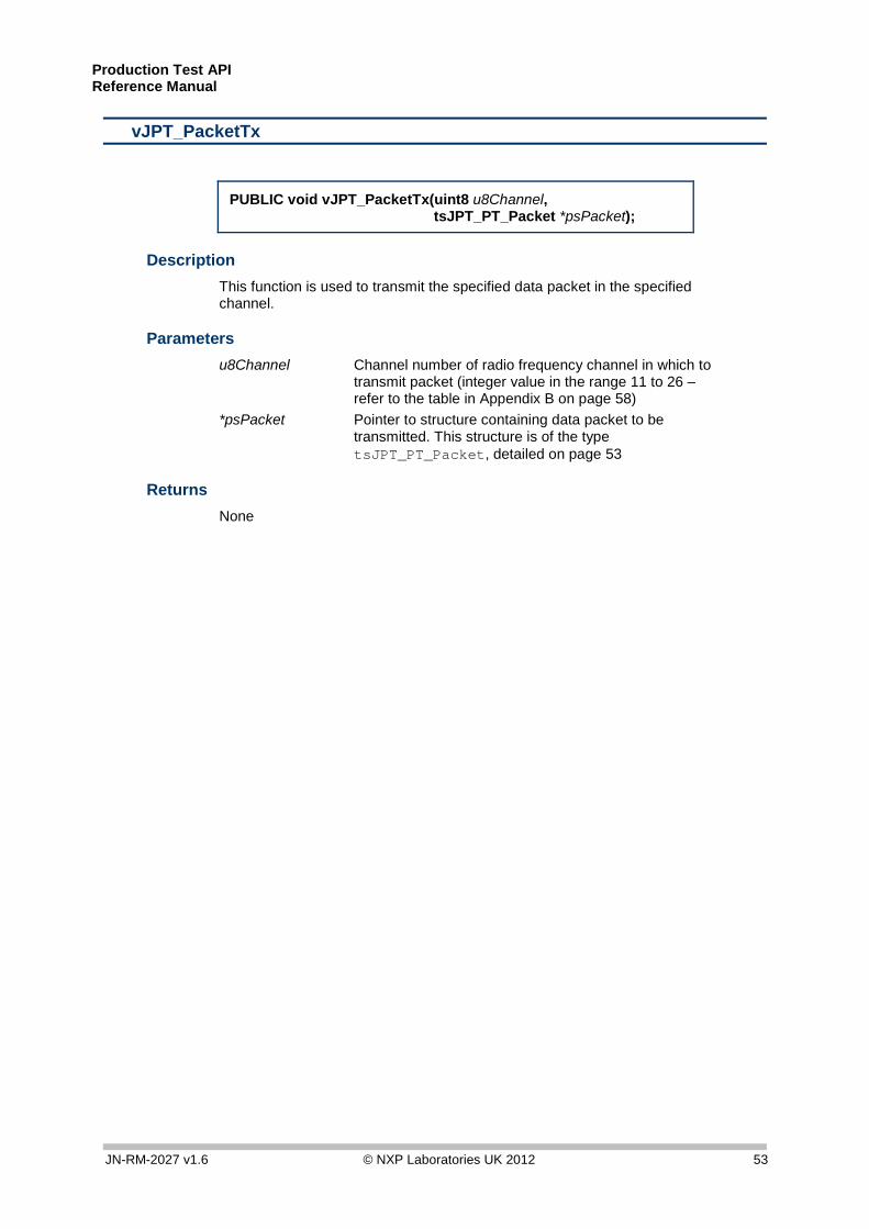
vJPT_PacketTx
PUBLIC void vJPT_PacketTx(uint8 u8Channel, tsJPT_PT_Packet *psPacket);
Description This function is used to transmit the specified data packet in the specified channel.
Parameters u8Channel Channel number of radio frequency channel in which to
transmit packet (integer value in the range 11 to 26 – refer to the table in Appendix B on page 58)
*psPacket Pointer to structure containing data packet to be transmitted. This structure is of the type tsJPT_PT_Packet, detailed on page 53
Returns None

Production Test API Reference Manual
54 © NXP Laboratories UK 2012 JN-RM-2027 v1.6
Production Test API Reference Manual
JN-RM-2027 v1.6 © NXP Laboratories UK 2012 55
Appendices The appendices below detail the data structures and the radio frequency channel numbering used by the Production Test API.
A Structures
The following structures are used by some functions of the API.
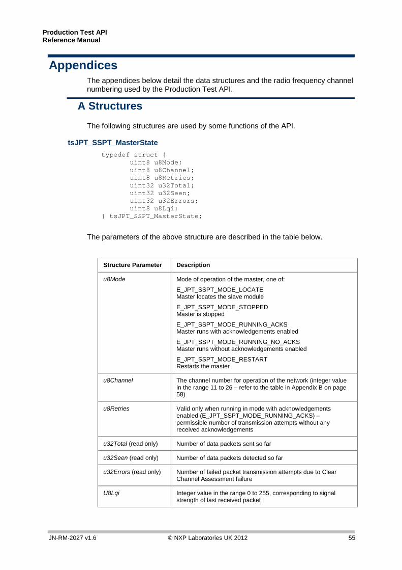
tsJPT_SSPT_MasterState typedef struct { uint8 u8Mode; uint8 u8Channel; uint8 u8Retries; uint32 u32Total; uint32 u32Seen; uint32 u32Errors; uint8 u8Lqi; } tsJPT_SSPT_MasterState;
The parameters of the above structure are described in the table below.
Structure Parameter Description
u8Mode Mode of operation of the master, one of:
E_JPT_SSPT_MODE_LOCATE Master locates the slave module
E_JPT_SSPT_MODE_STOPPED Master is stopped
E_JPT_SSPT_MODE_RUNNING_ACKS Master runs with acknowledgements enabled
E_JPT_SSPT_MODE_RUNNING_NO_ACKS Master runs without acknowledgements enabled
E_JPT_SSPT_MODE_RESTART Restarts the master
u8Channel The channel number for operation of the network (integer value in the range 11 to 26 – refer to the table in Appendix B on page 58)
u8Retries Valid only when running in mode with acknowledgements enabled (E_JPT_SSPT_MODE_RUNNING_ACKS) – permissible number of transmission attempts without any received acknowledgements
u32Total (read only) Number of data packets sent so far
u32Seen (read only) Number of data packets detected so far
u32Errors (read only) Number of failed packet transmission attempts due to Clear Channel Assessment failure
U8Lqi Integer value in the range 0 to 255, corresponding to signal strength of last received packet
Production Test API Reference Manual
56 © NXP Laboratories UK 2012 JN-RM-2027 v1.6
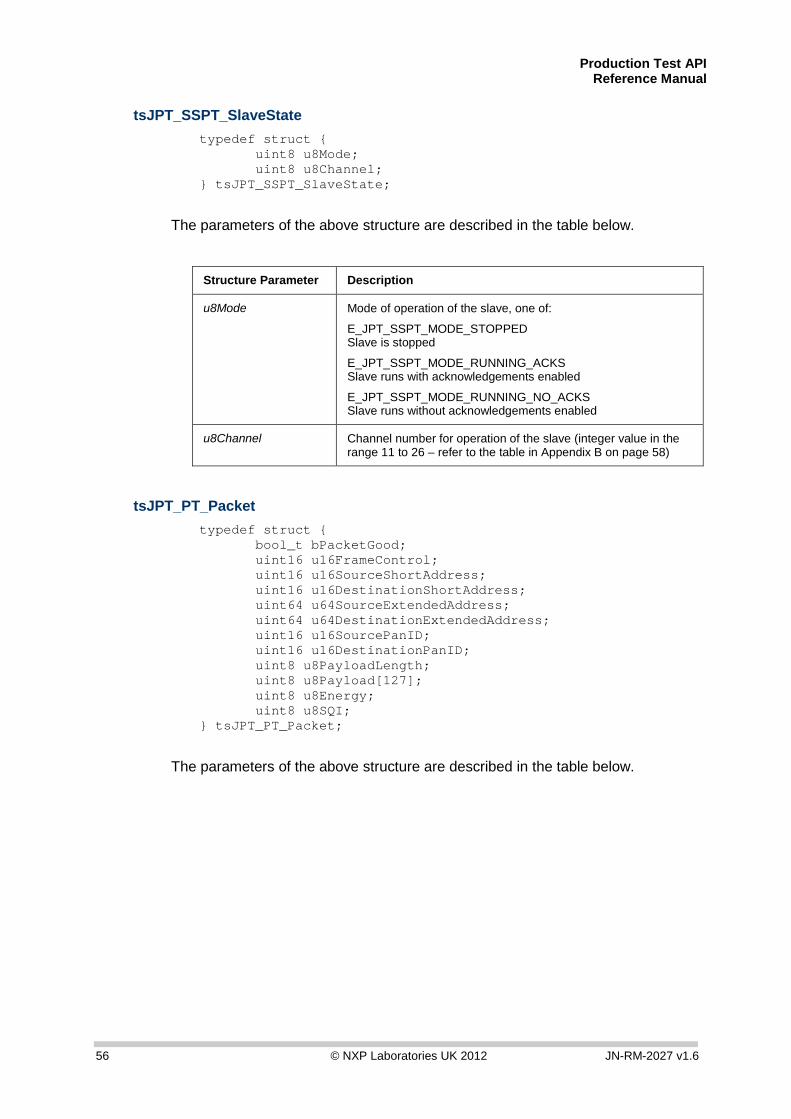
tsJPT_SSPT_SlaveState typedef struct { uint8 u8Mode; uint8 u8Channel; } tsJPT_SSPT_SlaveState;
The parameters of the above structure are described in the table below.
Structure Parameter Description
u8Mode Mode of operation of the slave, one of:
E_JPT_SSPT_MODE_STOPPED Slave is stopped
E_JPT_SSPT_MODE_RUNNING_ACKS Slave runs with acknowledgements enabled
E_JPT_SSPT_MODE_RUNNING_NO_ACKS Slave runs without acknowledgements enabled
u8Channel Channel number for operation of the slave (integer value in the range 11 to 26 – refer to the table in Appendix B on page 58)
tsJPT_PT_Packet typedef struct { bool_t bPacketGood; uint16 u16FrameControl; uint16 u16SourceShortAddress; uint16 u16DestinationShortAddress; uint64 u64SourceExtendedAddress; uint64 u64DestinationExtendedAddress; uint16 u16SourcePanID; uint16 u16DestinationPanID; uint8 u8PayloadLength; uint8 u8Payload[127]; uint8 u8Energy; uint8 u8SQI; } tsJPT_PT_Packet;
The parameters of the above structure are described in the table below.

Production Test API Reference Manual
JN-RM-2027 v1.6 © NXP Laboratories UK 2012 57
The parameters of the above structure are described in the table below.
Structure Parameter Description
bPacketGood For a received packet, indicates whether the data packet is valid (determined through checksum): TRUE Valid packet FALSE Invalid packet
For a transmitted packet, indicates whether an acknowledgement has been received: TRUE Acknowledgement received FALSE No acknowledgement received
u16FrameControl Determines which options (below) are implemented (see IEEE 802.15.4 specification, Section 7.2.1.1, for details)
u16SourceShortAddress 16-bit short (network) address of source node
u16DestinationShortAddress 16-bit short (network) address of destination node
u64SourceExtendedAddress 64-bit extended (IEEE/MAC) address of source node
u32DestinationExtendedAddress 64-bit extended (IEEE/MAC) address of destination node
u16SourcePanID PAN ID of source network
u16DestinationPanID PAN ID of destination network
u8PayloadLength Length of payload, in bytes (maximum is 128)
u8Payload[127] Array in which each element contains a byte of payload data. The first byte of data is contained in element 0. The array element of the final byte of data is determined by the payload length (u8PayloadLength – 1)
u8Energy Integer value in the range 0 to 255, corresponding to signal strength of received packet
u8SQI Integer value in the range 0 to 255, corresponding to signal quality of received packet
Production Test API Reference Manual
58 © NXP Laboratories UK 2012 JN-RM-2027 v1.6
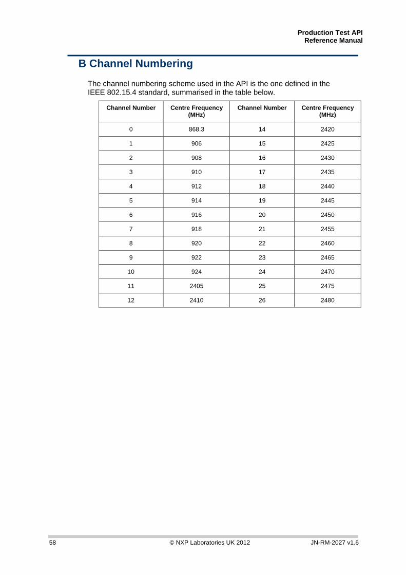
B Channel Numbering
The channel numbering scheme used in the API is the one defined in the IEEE 802.15.4 standard, summarised in the table below.
Channel Number Centre Frequency (MHz)
Channel Number Centre Frequency (MHz)
0 868.3 14 2420
1 906 15 2425
2 908 16 2430
3 910 17 2435
4 912 18 2440
5 914 19 2445
6 916 20 2450
7 918 21 2455
8 920 22 2460
9 922 23 2465
10 924 24 2470
11 2405 25 2475
12 2410 26 2480
Production Test API Reference Manual
JN-RM-2027 v1.6 © NXP Laboratories UK 2012 59
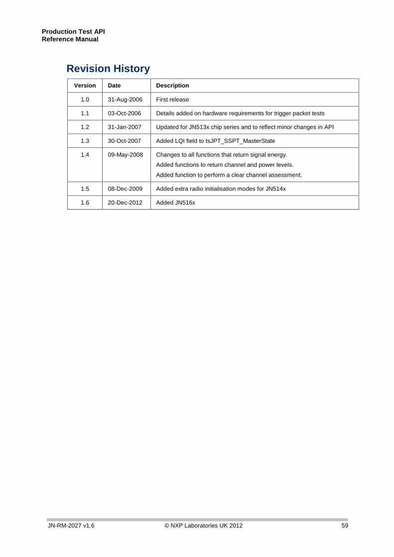
Revision History Version Date Description
1.0 31-Aug-2006 First release
1.1 03-Oct-2006 Details added on hardware requirements for trigger packet tests
1.2 31-Jan-2007 Updated for JN513x chip series and to reflect minor changes in API
1.3 30-Oct-2007 Added LQI field to tsJPT_SSPT_MasterState
1.4 09-May-2008 Changes to all functions that return signal energy.
Added functions to return channel and power levels.
Added function to perform a clear channel assessment.
1.5 08-Dec-2009 Added extra radio initialisation modes for JN514x
1.6 20-Dec-2012 Added JN516x

Production Test API Reference Manual
60 © NXP Laboratories UK 2012 JN-RM-2027 v1.6
Important Notice Limited warranty and liability — Information in this document is believed to be accurate and reliable. However, NXP Semiconductors does not give any representations or warranties, expressed or implied, as to the accuracy or completeness of such information and shall have no liability for the consequences of use of such information. NXP Semiconductors takes no responsibility for the content in this document if provided by an information source outside of NXP Semiconductors.
In no event shall NXP Semiconductors be liable for any indirect, incidental, punitive, special or consequential damages (including - without limitation - lost profits, lost savings, business interruption, costs related to the removal or replacement of any products or rework charges) whether or not such damages are based on tort (including negligence), warranty, breach of contract or any other legal theory.
Notwithstanding any damages that customer might incur for any reason whatsoever, NXP Semiconductors’ aggregate and cumulative liability towards customer for the products described herein shall be limited in accordance with the Terms and conditions of commercial sale of NXP Semiconductors.
Right to make changes — NXP Semiconductors reserves the right to make changes to information published in this document, including without limitation specifications and product descriptions, at any time and without notice. This document supersedes and replaces all information supplied prior to the publication hereof.
Suitability for use — NXP Semiconductors products are not designed, authorized or warranted to be suitable for use in life support, life-critical or safety-critical systems or equipment, nor in applications where failure or malfunction of an NXP Semiconductors product can reasonably be expected to result in personal injury, death or severe property or environmental damage. NXP Semiconductors and its suppliers accept no liability for inclusion and/or use of NXP Semiconductors products in such equipment or applications and therefore such inclusion and/or use is at the customer’s own risk.
Applications — Applications that are described herein for any of these products are for illustrative purposes only. NXP Semiconductors makes no representation or warranty that such applications will be suitable for the specified use without further testing or modification.
Customers are responsible for the design and operation of their applications and products using NXP Semiconductors products, and NXP Semiconductors accepts no liability for any assistance with applications or customer product design. It is customer’s sole responsibility to determine whether the NXP Semiconductors product is suitable and fit for the customer’s applications and products planned, as well as for the planned application and use of customer’s third party customer(s). Customers should provide appropriate design and operating safeguards to minimize the risks associated with their applications and products.
NXP Semiconductors does not accept any liability related to any default, damage, costs or problem which is based on any weakness or default in the customer’s applications or products, or the application or use by customer’s third party customer(s). Customer is responsible for doing all necessary testing for the customer’s applications and products using NXP Semiconductors products in order to avoid a default of the applications and the products or of the application or use by customer’s third party customer(s). NXP does not accept any liability in this respect.
Export control — This document as well as the item(s) described herein may be subject to export control regulations. Export might require a prior authorization from competent authorities.
NXP Laboratories UK Ltd (Formerly Jennic Ltd)
Furnival Street Sheffield S1 4QT
United Kingdom
Tel: +44 (0)114 281 2655 Fax: +44 (0)114 281 2951
For the contact details of your local NXP office or distributor, refer to:
www.nxp.com/jennic