Embed Size (px)
Citation preview
WHC-SA-2786-FP C O F ) * ~ / ~ - - c I . .
1 .
Production Reactor Disposal on the Hanford Site
Prepared for the U.S. Department of Energy Assistant Secretary for Environmental Management
Westinghouse Hanford Company Richland, Washington
Management and Operations Contractor for the U.S. Department of Energy under Contract DE-AC06-87RL10930
CEWE
O S T I JAN 3 0 19%
~~
CopVrioht Licsnn By acceptance of this &de, the publisher andlor r e c i p i i t acknowledges the U.S. Government's rbht to retain a nonexclusive, roydty-free license in and to my copyright covering this paper.
Approved for public release
i r
LEoALDlSUAINlER This report was prepared as an account of work sponsored by an agency of the United States Government. Neither the United States Government nor any agency thereof, nor any of their employees, nor any of their contractors, subcontractors or their employees, makes any warranty, express or implied, or assumes any legal liability or responsibility for the accuracy, completeness, or any third party's use or the results of such use of any information, apparatus, product, or process disclosed, or represents that its use would not infringe privately owned rights. Reference herein to any specific commercial product, process, or senice by trade name, trademark, manufacturer, or otherwise, does not necessarily constitute or imply its endorsement, recommendation, or favoring by the United States Government or any agency thereof or its contractors or subcontractors. The views and opinions of authors expressed herein do not necessarily state or reflect those of the United States Government or any agency thereof.
This report has been reproduced from the best available copy.
Rintod in the United SWoa of America
DISCLM-2.CHP (1-91)
WHC-SA-2786-FP
Production Reactor Disposal on the Hanford Site T. Romano Westinghouse Hanford Company
R. L. Miller Bechtel Hanford, Inc.
Date Published December 1995
To Be Presented at PAlRAM '95 1 1 th international Conference on the Packaging and
Las Vegas, Nevada December 3-8, 1995
Transportation of Radioactive Materials
Prepared for the U.S. Department of Energy Assistant Secretary for Environmental Management
Westinghouse P.0 Box 1970 Hanford Company Richland, Washington
Management and Operations Contractor for the U.S. Department of Energy under Contract DE-AC0887RL10930
Copyright LicaMa By acce+&mca of this &de, the publishsr mdlor recipient acknowledges the US. Government's k h t to ret& a nonexclusive, royalty-free license in md to any copyright covering this paper.
Approved for public release


INTRODUCTION
One of the many restoration challenges for the Hanford Site is the disposal of eight plutonium production reactors inactive since 197 1. In order to minimize environmental and public health and safety impacts disposal alternatives were evaluated in an Environmental Impact Statement (EIS). Alternatives considered were no action, immediate one-piece removal, safe storage followed by deferred one-piece removal, safe storage followed by deferred dismantlement, and in-situ decommissioning. Evaluation of the EIS by the U.S. Department of Energy resulted in the selection of the safe storage followed by one-piece removal alternative.
A typical reactor block consists of a graphite moderator stack encased in a cast iron thermal shield surrounded by a thick biological shield. The entire assembly rests on a massive concrete base and foundation. A typical reactor block is shown in Figure 1. Overall dimensions are 14 m high, 14 m wide, and 12.2 m long (46 fi x 46 fi x 40 fi). The estimated weight of the reactor block when packaged and ready for transport is about 12,000 tonnes for the six smaller (C type) reactors and nearly 16,000 tonnes for the two larger (K type) reactors. This project will represent the largest single lift and transport task ever attempted.
In order to quantify the radionuclide inventories in the reactor blocks with reasonable accuracy, samples of the thermal shield and biological shield as well as graphite were obtained. The sampling information was used to determine the location and calculate the activity of radionuclides contained in the reactor blocks. Evaluations were performed to determine the transportation classification and packaging requirements.
One piece removal of the reactor block will be preceded by conventional decontamination and decommissioning (D&D) of the reactor building and contaminated reactor peripheral equipment and components. Contaminated materials resulting from the D&D efforts will be packaged and disposed of in a burial facility on the Hanford Site. Following the safe storage period the reactor blocks will be packaged, loaded onto a specially constructed transporter system and transported to a specially constructed burial facility located in the 200 West Area of the H d o r d Site.
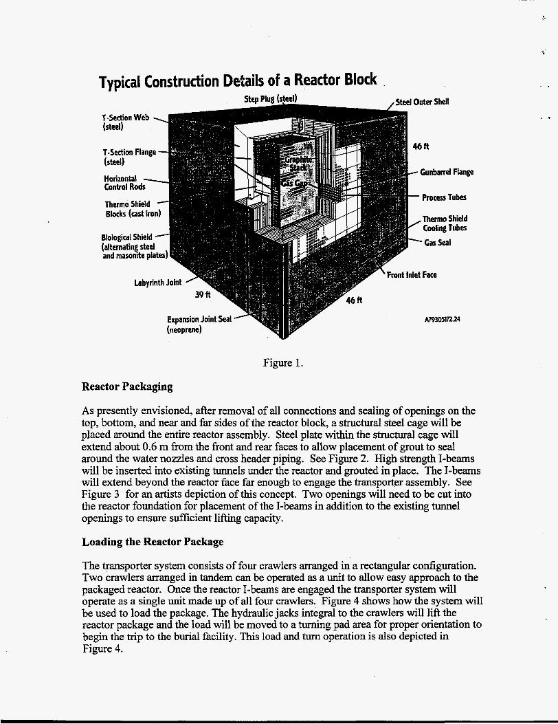
Typical Construction Details of a Reactor Block
Figure 1.
Reactor Packaging
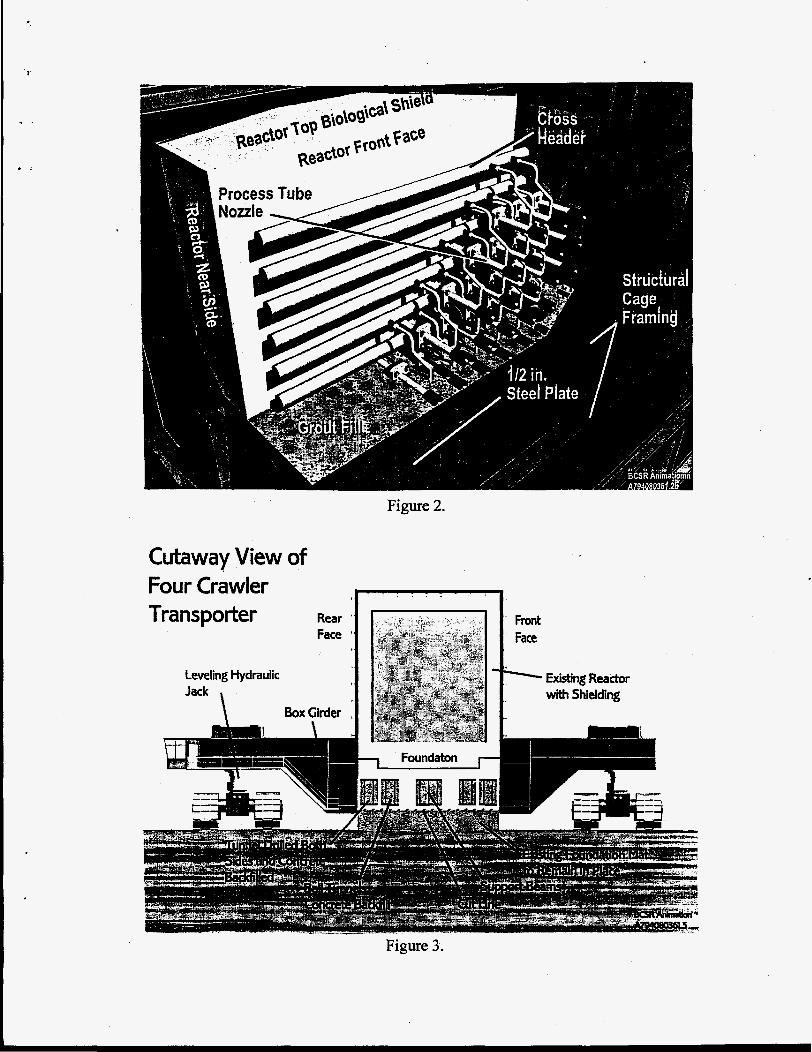
As presently envisioned, after removal of all connections and sealing of openings on the top, bottom, and near and far sides of the reactor block, a structural steel cage will be placed around the entire reactor assembly. Steel plate within the structural cage will extend about 0.6 m from the front and rear faces to allow placement of grout to seal around the water nozzles and cross header piping. See Figure 2. High strength I-beams will be inserted into existing tunnels under the reactor and grouted in place. The I-beams will extend beyond the reactor face far enough to engage the transporter assembly. See Figure 3 for an artists depiction of this concept. Two openings will need to be cut into the reactor foundation for placement of the I-beams in addition to the existing tunnel openings to ensure sufficient lifting capacity.
Loading the Reactor Package
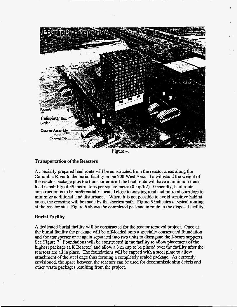
The transporter system consists of four crawlers arranged in a rectangular configuration. Two crawlers arranged in tandem can be operated as a unit to allow easy approach to the packaged reactor. Once the reactor I-beams are engaged the transporter system will operate as a single unit made up of all four crawlers. Figure 4 shows how the system will be used to load the package. The hydraulic jacks integral to the crawlers will lift the reactor package and the load will be moved to a turning pad area for proper orientation to begin the trip to the burial facility. This load and turn operation is also depicted in Figure 4.
1 Process Tube ~
Cutaway View of Four Crawler Transporter
. . . . . . 1. I Rear a
Face I
Leveling Hydraulic Jack
BoxGirder , \
Foundaton I-
Existing Reactor with Shielding
4
Transportation of the Reactors
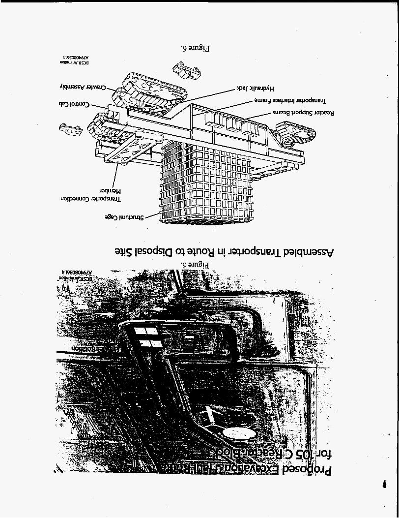
A specially prepared haul route will be constructed fiom the reactor areas along the Columbia River to the burial facility in the 200 West Area. To withstand the weight of the reactor package plus the transporter itself the haul route will have a minimum track load capability of 39 metric tons per square meter (8 kip/ft2). Generally, haul route construction is to be preferentially located close to existing road and railroad corridors to minimize additional land disturbance. Where it is not possible to avoid sensitive habitat areas, the crossing will be made by the shortest path. Figure 5 indicates a typical routing at the reactor site. Figure 6 shows the completed package in route to the disposal facility.
Burial Facility
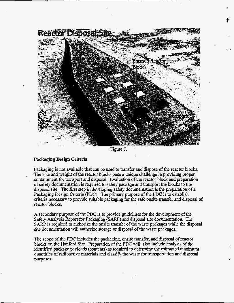
A dedicated burial facility will be constructed for the reactor removal project. Once at the burial facility the package will be off-loaded onto a specially constructed foundation and the transporter once again separated into two units to disengage the I-beam supports. See Figure 7. Foundations will be constructed in the facility to allow placement of the highest package (a K Reactor) and allow a 3 m cap to be placed over the facility after the reactors are all in place. The foundations will be capped with a steel plate to allow attachment of the steel cage thus forming a completely sealed package. As currently envisioned, the space between the reactors can be used for decommissioning debris and other waste packages resulting fiom the project.
Packaging Design Criteria
Packaging is not available that can be used to transfer and dispose of the reactor blocks. The size and weight of the reactor blocks pose a unique challenge in providing proper containment for transport and disposal. Evaluation of the reactor block and preparation of safety documentation is required to safely package and transport the blocks to the disposal site. The first step in developing safety documentation is the preparation of a Packaging Design Criteria (PDC). The primary purpose of the PDC is to establish criteria necessary to provide suitable packaging for the safe onsite transfer and disposal of reactor blocks.
A secondary purpose of the PDC is to provide guidelines for the development of the Safety Analysis Report for Packaging (SARP) and disposal site documentation. The S A R P is required to authorize the onsite transfer of the waste packages while the disposal site documentation will authorize storage or disposal of the waste packages.
t
The scope of the PDC includes the packaging, onsite transfer, and disposal of reactor blocks on the Hanford Site. Preparation of the PDC will also include analysis of the identified package payloads (contents) as required to determine the estimated maximum quantities of radioactive materials and classify the waste for transportation and disposal purposes.
r i
The waste packaging and transportation concepts described in the PDC involve the design and fabrication of a new packaging. Development and use of new packaging containers requires that a safety analysis, risk assessment, thermal analysis, structural analysis, and shielding analysis be applied to assure that all anticipated events are addressed.
The safety of onsite transfers will be based on providing an equivalent degree of safety as would be provided by the U.S. Department of Transportation (DOT) regulations. This equivalent degree of safety will be documented in the SARP. A combination of packaging design analysis and risk assessment will be employed in the S A R P evaluation process. The S A R P analysis will demonstrate the ability of the packaging to provide containment for normal transfer conditions and, if required, for designated accident conditions.


![B215 AC06 My Boutique_6th Presentation_04May2009 [Part 1]](https://img.pdfslide.us/doc/110x75/577d38391a28ab3a6b975731/b215-ac06-my-boutique6th-presentation04may2009-part-1.jpg)