Embed Size (px)
Citation preview

CCEMC EOI # K130091 Final Report: May 2016
1
Project ID EOI # K130091
Final Report Public Release
Production of Dimethyl Carbonate (DMC) from
Captured CO2 and Methanol
By
E3Tec Service, LLC 1 Denali Court
South Barrington, Illinois 60010-1061
USA
Principal Investigator
Dr. Chandrakant B. Panchal
E3Tec Service, LLC
Project Advisor
Dr. Duke DuPlessis
Alberta Innovates
Calgary, Alberta
Canada
Completion Date: June 2016
May 2016

CCEMC EOI # K130091 Final Report: May 2016
2
Table of Contents
1 EXECUTIVE SUMMARY ................................................................................................... 5
2 PROJECT DESCRIPTION .................................................................................................... 8
2.1 Introduction and Background ...................................................................................... 8 2.2 Technology Description ................................................................................................. 9
2.2.1 Urea-Based DMC Process ........................................................................................ 9 2.2.2 Ethylene Oxide Based DMC Process ....................................................................... 9
2.3 Project Goals ................................................................................................................. 11
2.4 Work Scope Overview ................................................................................................. 11
3 OUTCOMES AND LEARNING ........................................................................................ 13
3.1 Literature Survey ......................................................................................................... 13 3.2 Technology Development ............................................................................................. 15
3.3 Experimental Procedures and Methodology ............................................................. 16 3.3.1 Kinetic Tests ........................................................................................................... 16
3.3.2 PerVap Performance Tests ...................................................................................... 18 3.3.3 Validation Tests with Prototype Test Units ............................................................ 19
3.4 Modeling Details ........................................................................................................... 21
3.4.1 Kinetic Model ......................................................................................................... 21 3.4.2 ASPEN Plus® Process Models ............................................................................... 22
3.4.3 Integration of DMC Process ................................................................................... 23 3.5 Results and Discussion ................................................................................................. 26
3.5.1 Kinetic Parameters .................................................................................................. 26
3.5.2 PerVap Performance ............................................................................................... 27
3.5.3 Prototype Test Results ............................................................................................ 28 3.5.4 Process Analysis ..................................................................................................... 28 3.5.5 Design of Pilot Plant ............................................................................................... 30
3.6 Project Outcome ........................................................................................................... 33 3.7 Lessons Learned ........................................................................................................... 34
4 GREENHOUSE GAS AND NON-GHG IMPACTS .......................................................... 35
4.1 Impact of CO2 Conversion to DMC on GHG Emission ................................................ 35 4.2 C-Footprint Analysis ...................................................................................................... 35 4.3 C-Footprint of Raw Materials ........................................................................................ 38
4.4 CO2 Emission Abatement .............................................................................................. 40 4.5 Challenges and Opportunities ........................................................................................ 42
5 OVERALL CONCLUSION ................................................................................................ 42
6 SCIENTIFIC ACHIEVEMENTS ........................................................................................ 43
7 PROGRAMMATIC ACHIEVEMENTS ............................................................................. 44
8 NEXT STEPS ...................................................................................................................... 46
8.1 Technology Innovation ................................................................................................ 46 8.2 Commercialization Plan .............................................................................................. 46
9 COMMUNICATIONS PLAN ............................................................................................. 47

CCEMC EOI # K130091 Final Report: May 2016
3
List of Figures
Figure 3-1: Supply chain of Dimethyl Carbonate (DMC) ............................................................ 14
Figure 3-2: Global DMC demands 2015 ..................................................................................... 14
Figure 3-3: Schematic diagram of scaling the catalytic process from lab to commercial plants.. 16
Figure 3-4: Schematic diagram and pictorial view of the DKTU. ............................................... 17
Figure 3-5: Flow schematic of the PerVap test unit. .................................................................... 19
Figure 3-6: Pictorial view of the PerVap test unit. ....................................................................... 19
Figure 3-7: Process diagram of the prototype test unit for the urea based process. ..................... 20
Figure 3-8: Process diagram of the prototype test unit for the ethylene oxide based process. ..... 21
Figure 8-1: E3Tec commercialization plan. .................................................................................. 47

CCEMC EOI # K130091 Final Report: May 2016
4
List of Tables
Table 3-1: Characterization of CO2 from three sources................................................................ 24
Table 3-2: Design parameters of a commercial scale process unit. .............................................. 30
Table 3-3: Process parameter of the pilot plant for the urea-based process. ............................... 32
Table 3-4: Process parameters of the pilot plant for the ethylene oxide-based process. .............. 33
Table 4-1: C-Footprint of the urea-based process. ........................................................................ 37
Table 4-2: C-Footprint of the ethylene oxide-based process. ....................................................... 38
Table 4-3: C-Footprint of the SynGas-based Versalis process. .................................................... 38
Table 4-4: Alberta's CO2 abatement potentials by four major applications of DMC. .................. 41
CCEMC EOI # K130091 Final Report: May 2016
5
1 EXECUTIVE SUMMARY
In the past two centuries, fossil fuels – coal, petroleum and natural gas – have played a key role in
establishing the modern world. They have allowed for affordable electricity, the development of high-
speed long-distance transportation, the supply of potable water, and the production of ammonia fertilizers
with direct impact on food production. Between 1980 and 2012 the global demand for electricity
increased from 8.3 to 22.7 million GWh, and the resulting annual CO2 emissions increased from 5.5 to
13.3 trillion tonnes. The impact of rising CO2 levels on the climate is now taken seriously as
demonstrated by the COP21 meeting in Paris (December 2015). The accord from COP21 is expected to
stimulate global action to reduce CO2 emissions, as well as to find economic ways to convert CO2 to
products. Recent announcements by major oil and gas companies show that industry is ready for
serious engagement on this issue. Considering the magnitude of the issue, every effort to stabilize and
then reduce CO2 levels in the atmosphere will be required. The challenges associated with CO2 capture
and storage (CCS) have been well documented. Since few of the major industrial and utility CO2 sources
are located close to CO2 storage sites, additional and substantial transportation and injection costs will be
incurred. Converting captured CO2 to value-added products such as DiMethyl Carbonate (DMC) via
the proposed process would eliminate CO2 transportation and storage costs from distributed CO2
sources. It encourages facilities to convert CO2 into a revenue stream that would benefit Alberta.
E3Tec’s project focuses on the CCEMC mission of reducing Alberta CO2 emissions by using CO2 as
a feedstock to manufacture DMC, an ideal chemical for CO2 conversion because of its expanding
applications in current and emerging markets. DMC presently is used for manufacturing polycarbonates
– replacing a more hazardous phosgene-based route, it is used as a low VOC solvent, and as an electrolyte
solvent in lithium-ion batteries. It is being evaluated as an oxygenated fuel additive for diesel. DMC is
also used to produce isocyanates, a family of chemicals with high industrial use as an intermediate for
manufacture of polyurethane and synthetic materials.
The governing objective of this Grand Challenge project was to develop a process for converting
captured CO2 to the value-added product di-methyl carbonate (DMC). There is a growing global demand
and emerging new applications for DMC. The E3Tec team understands that no one technology alone can
meet Alberta’s 2008 Climate Change Strategy; however, by converting captured CO2 to DMC, E3Tec’s
technology would be part of the portfolio for making significant contributions to the overall goal within
the desired time frame. The E3Tec Team, in partnership with Michigan State University (MSU), has
developed an innovative energy-efficient process; combining heat-integrated reactive distillation (HIRD)
with side reactors equipped with either PerVaporation (PerVap) membranes or side reboilers for
separation of byproduct and excess reactants. With a low Carbon-Footprint, the CO2-based DMC has
potentials for significant abatement of CO2 in Alberta.
The major scientific achievements were: a) development of ASPEN Plus® design methodology of
two CO2-based DMC processes; b) establishment of CO2 abatement potentials; c) competitive edge of the
CO2-based DMC process to conventional SynGas-based DMC process; d) development of the databases
of kinetic parameters and performance parameters using prototype test units for validating the ASPEN
Plus® design model; and e) pilot plant design for demonstrating the technology in Alberta.
The four DMC market opportunities that would result in significant CO2 abatement are: a)
polycarbonates; b) environmentally friendly solvents; c) lithium-ion batteries; and d) a potential fuel
additive to diesel. All together these markets constitute the potential for greater than 9 million
tonnes/year of CO2 abatement with 25% market share of the global demands as shown in table below.
Alberta would become a major manufacturing center of CO2-based DMC for exporting to the US, Asia,
and Europe.

CCEMC EOI # K130091 Final Report: May 2016
6
Application
2016 Global
Demands
kTA
Growth
kTA
25% Market
Penetration
DMC in
Product
CO2 Abatement
Potentials, kTA
Growth 25% Market
Polycarbonate 6,430 444 1,608 1.0 129 466
Solvents (Replacing Ketones) 1,430 29 358 1.0 23 286
Fuel Additives (Diesel) 1,580,000 31,600 395,000 0.076 700 8,752
Lithium-Ion Battery $25 billion/yr Electrolyte market $5.23
billion/yr
227
In addition to technical accomplishments, there were significant programmatic achievements. E3Tec
has secured strong IP positions through patent protection in “Method for Producing Concentrated
Dimethyl Carbonate Composition and Co-Products,” US # 14/445,992 (Patent Issued) and “Differential
Kinetic Test Unit (DKTU),” US Patent 9,222,924 (December 2015). The ASPEN Plus® design
methodology provides the basic foundation for rapidly scaling laboratory data and pilot plant performance
parameters to commercial plants. E3Tec received US SBIR Phase I grant for developing an alternate
process to convert of CO2 to DMC using ethylene oxide as feedstock. This process produces mono-
ethylene glycol (MEG) as coproduct and this should improve the process techno-economic viability.
E3Tec team members visited Enerkem and Alberta Innovates Technology Futures in July 2014 to explore
collaboration and evaluate sites for demonstration of the technology in Round 2. Collaboration with
Enerkem will focus on methanol produced from municipal waste as feedstock for the DMC process and
potentially an integrated DMC-Methanol process. The integrated process is expected to significantly
improve the overall C-Footprint by eliminating liquefaction or pressuring for transportation of CO2.
E3Tec is exploring potential collaboration with Illinois Sustainability Technology Center (ISTC),
Champaign, Illinois for developing an integration process of CO2 capture and conversion.
The major conclusions from Round 1 projects in three categories are as follow.
CO2 Abatement Target
1. DMC is an ideal value-added specialty chemical with expanding global market for conversion of
CO2 to value-added product.
2. Both the urea-based and ethylene oxide-based processes showed potentials for significant CO2
abatement in Alberta.
3. Methanol produced using the conventional SynGas process has a high C-Footprint. Therefore,
biomass or renewable energy based methanol must be pursed.
4. Integration of CO2 capture and conversion with the process showed high potential for significant
CO2 abatement from coal utility plants in Alberta.
5. Integration of the DMC process with SynGas methanol manufacturing has potentials for
significant CO2 abatement; therefore, it should be pursued with the Methanex plant in Alberta.
6. An integrated DMC-MEG process has favorable techno-economic merits; therefore, it should be
pursued with ethylene plants in Alberta.
Process Development
7. The ASPEN Plus® process model, along with component models, developed in this project are
shown to be very valuable design tools for evaluating and configuring the process to meet the
desired goal of CO2 abatement with favorable economics.

CCEMC EOI # K130091 Final Report: May 2016
7
8. Heat Integrated Reactive Distillation (HIRD) equipped with side reactors and PerVap membranes
is ideally suited for the complex process chemistry of conversion of CO2 to alkyl carbonates.
9. Catalyst ZnO forms organometallic complex with urea in the urea-based process. The ZnO-
complex is sparingly soluble in reacting media, which required E3Tec to modify the original
process configuration based on totally heterogeneous catalyst. In Round 2, an alternate design for
the side reactors will be developed to maximize DMC yield and high rates of conversion.
10. Commercial Amberlyst® catalyst performed well for conversion of ethylene carbonate to DMC
in the ethylene oxide-based process. The process can be readily scaled to a fully integrated pilot
plant demonstration.
11. Performance parameters of the ceramic tubular PerVap membranes provided a basis for
integrating them into the process to improve product yield. This permits the trade-off analysis of
energy efficiency vs. capital cost of PerVap and process equipment.
12. ASPEN Plus® process modeling was effectively validated with prototype tests. The next step is
to validate the process model with an integrated pilot-plant.
Technology Transfer
13. CO2-based DMC process is getting encouraging responses from industry and research
organizations.
14. Technology transfer plans developed in this project show a well-defined roadmap for
commercially implementing CO2-based DMC production in Alberta using this process.
15. CO2-based DMC process shows favorable techno-economic merits in comparison to the
conventional SynGas based DMC process that is being considered for replacing current
commercial phosgene-based polycarbonate processes.
16. Demonstration of an integrated DMC process and reliable economic analysis are key to
commercialization of the DMC process in Alberta.
During Round 1 of the CCEMC project, E3Tec’s team advanced the DMC process development from
Technology Readiness Level (TRL) 3 of Critical Function or Proof of Concept Established to TRL 5 of
Laboratory Testing of Integrated/Semi-Integrated System. In Round 2, E3Tec expects to advance it to
TRL-7 of Integrated Pilot System Demonstrated. The ASPEN Plus® process model provided the basic
foundation for rapidly scaling laboratory data and pilot plant performance parameters to commercial
plants.

CCEMC EOI # K130091 Final Report: May 2016
8
2 PROJECT DESCRIPTION
2.1 Introduction and Background
In the past two centuries, fossil fuel supplied by coal, petroleum, and natural gas has played a key role
in establishing the modern world economy. It has allowed affordable electricity, the development of a
global transportation network, the supply of potable water, and manufacture of chemicals such as
ammonia with a direct impact on food production. When the global demand for electricity increased from
8.3 million GWh in 1980 to 22.7 million GWh in 2012,1 the resulting annual CO2 emission increased
from 5.5 to 13.3 trillion tonnes. Today the global demand for energy-intensive products, such as
ammonia and plastics, continues to expand with the growing population and improved standards of living
in emerging markets. The impact of rising CO2 levels on climate change is now taken seriously as
demonstrated by the COP21 meeting in Paris (December 2015) which is stimulating global action to
reduce CO2 emissions. In response the major oil and gas companies have outlined economic solutions;
one of which is CO2 conversion to products.2 Considering the magnitude of the issue, all efforts will be
required to stabilize and then reduce CO2 levels in the atmosphere.
The challenges associated with CO2 capture, transport, and storage have been well documented. The
Global CCS Institute recently published a cost analysis for CO2 capture, transport, and storage in the
European Union.3 This report looked at transport costs via pipeline or ship and included costs associated
with single and multiple sources and sinks. The report highlighted the challenges and costs of
coordinating the development of a CO2 transportation infrastructure. Since few of the major industrial
and utility CO2 sources are located close to CO2 storage sites, additional and substantial transportation
and injection costs will be incurred. Delivering the CO2 to the fence at pipeline pressure (130 bar) raises
the energy cost to 1.16 kW/kg CO2 4 and this differential cost for liquefaction and pumping (0.35 kW/kg
CO2) will increase the energy consumption. The costs of pipeline transport followed by further
pressurization to move the CO2 into pore cavities 1-2 km deep are additional energy costs. Recognizing
this, chemical conversion of CO2 at an on-site merchant facility producing a marketable product should be
a high priority for providing an economically important alternate path. CO2 sources such as hydrogen
plants that employ amines, or raw natural gas processing facilities appear to be the most economical
sources for CO2. Two recent projects support this. In November 2015 Shell’s Quest carbon capture and
storage (CCS) project near Fort Saskatchewan, Alberta, Canada started-up and will capture approximately
1 MMtpy of CO2 from the hydrogen plant at the Scotford Upgrader for underground sequestration. In
December 2015, the Sturgeon Bitumen Refinery in Alberta started up, again with CO2 capture from the
hydrogen plant.
A recent AIChE/DOE sponsored Carbon Management Technology Conference (CMTC) meeting
(Sugar Land, TX, November 2015) focused on techno-economic barriers of carbon capture and
sequestration (CCS). Other than the CCEMC Grand Challenge program, there is limited activity on CO2
utilization. E3Tec was able to make effective comments on expanding the scope of the DOE’s Carbon
Management plan to include CO2 utilization in the overall portfolio. Other attendees also voiced similar
opinions on CO2 utilization. The outcome from this conference was that there would be increased focus
on CO2 utilization.
1 As appetite for electricity soars, the world turning to coal, Washington Post News Report, (October 16, 2015). 2 Oil and gas CEOs jointly declare action on climate change, PennEnergy e-news report, (October 19, 2015). 3 “The Cost of CO2 Capture, Transport, and Storage,” Zero Emissions Platform, Global CCS Institute, (July 2011). 4 Doctor, R.D. , Future of CCS Adoption at Existing PC Plants Economic Comparison of CO2 Capture and Sequestration from Amines and
Oxyfuels, Argonne Report, ANL/ESD/12-9 (Dec. 29, 2011).

CCEMC EOI # K130091 Final Report: May 2016
9
2.2 Technology Description
The E3Tec Team, in partnership with Michigan State University (MSU), has developed an innovative
energy-efficient process built upon heat-integrated reactive distillation (HIRD). The HIRD with side
reactors is equipped with either PerVaporation (PerVap) membranes or side reboilers for separation of
byproduct and excess reactant. This highly integrated process converts captured CO2 to alkyl carbonate,
specifically Di-Methyl Carbonate (DMC). Originally, E3Tec proposed urea-based process for conversion
of CO2 to DMC. However, after completing US DOE SBIR Phase I project of conversion of CO2 to
DMC using ethylene oxide as co-feedstock with mono ethylene glycol (MEG) and evaluating its techno-
economic merits, E3Tec decided to consider both processes for the CCEMC project.
2.2.1 Urea-Based DMC Process
The urea-based process is based on the following chemical pathway.
2 NH3 + CO2 → H2NCONH2 + H2O
Ammonia Carbon Dioxi Urea Water
H2NCONH2 + 2 CH3OH ↔ CH3OCOOCH3 + 2 NH3
Urea Methanol DMC Ammonia (recycled)
The process consists of two steps: A) reacting CO2 with ammonia to form urea; and B) further
reaction of urea with methanol for DMC synthesis that releases ammonia for recycle back to the urea
process. As such, ammonia acts as a chemical reaction carrier. Step A is a well-established commercial
process for manufacturing urea fertilizer; therefore, it was not included in the Round 1 scope of work.
The commercial process consists of a reaction column to which two or more side reactors are
connected, two fractionation columns for product recovery, and one fractionation column for separating
ammonia released in the process for recycle. It was discovered in Round 1 that zinc forms an
organometallic Zn-complex and it is partially soluble in the reacting media. Therefore, the reaction
product from each side reactor is fed to the reaction column and the product is separated while unreacted
urea, intermediate products, and Zn-complex catalyst are collected at the bottom of the column and
recirculated with recovered methanol. In Round 2, tests will be performed with side reactors packed with
ZnO to maintain an optimum level of active Zn-complex in the system. The product stream is fed to the
separation system consisting of fractionation columns and a PerVap membrane. Ammonia released in the
process is recycled to react with fresh CO2 forming urea. Methanol recovered from the fractionation and
PerVap membrane also is recycled. A process stream consisting of unreacted intermediate methyl
carbamate (MC) is recycled to the reactor feed with recycled methanol. Based on the preliminary ASPEN
Plus™ process analysis, DMC purity and yield would be greater than 99.9% and greater than 78%,
respectively. The yield is affected by formation of byproduct n-methyl methyl carbamate (NMMC),
which has product value, and decomposition of DMC in the presence of the Zn-complex catalyst.
2.2.2 Ethylene Oxide Based DMC Process
As reported previously, E3Tec received a DOE/SBIR Phase I grant in 2015 for the development of
the DMC process using ethylene oxide as co-feedstock with co-production of mono-ethylene glycol
(MEG). The Phase I project was completed in November 2015 and E3Tec was awarded a Phase II grant.
The overall scope of this SBIR Phase I project was very similar to the early part of the CCEMC project;
therefore, the two projects were carried out in parallel in order to leverage the effort. As a result, the
CCEMC project has benefitted from the expanded scope and both the originally proposed urea-based

CCEMC EOI # K130091 Final Report: May 2016
10
DMC process and the ethylene-oxide-based DMC process will be considered in Round 2 to improve the
techno-economic viability of commercial DMC plants in Alberta.
Like the urea-based process, this process consists of two steps: A) reacting CO2 with ethylene oxide
to form ethylene carbonate; and B) further reaction of ethylene carbonate with methanol for synthesis of
DMC and MEG. Step A is a well-established commercial process for manufacturing ethylene carbonate;
therefore, it is not included in the present scope of work.
CH2OCH2 + CO2 → CH2OCOOCH2
Ethylene Oxide Ethylene Carbonate (EC)
CH2OCOOCH2 + 2 CH3 OH ↔ CH3OCOOCH3 + CH2OHCH2OH
Ethylene Carbonate (EC) Methanol DMC Ethylene Glycol (EG)
The process consists of three distillation columns, four side reactors and one PerVap membrane unit.
Ethylene oxide readily reacts with CO2 to form ethylene carbonate (EC) releasing heat that can be used in
the downstream process. Ethylene carbonate is pre-reacted with excess methanol in a packed-bed reactor.
Most of the methanol and DMC are removed from the effluent and sent to product recovery columns.
Because there is a methanol/DMC azeotrope, the methanol is only purified in the methanol recovery
column to 88 wt% before being recycled to the side reactors and pre-reactor. PerVap membranes are
integrated with the process for recovering methanol and also for breaking the azeotrope. Integration of the
PerVap membrane improves the energy efficiency and hence reduces the C-Footprint in addition to
reducing the size of methanol recovery column.
Considering the high costs of PerVap membranes, a trade-off analysis will be performed to optimize
the design based on CAPEX and energy efficiency. DMC is purified to 99.99 wt% in the product
recovery column. The remaining pre-reacted effluent is fed to the reaction column where ethylene glycol
and unreacted EC are separated. The ethylene glycol is removed as a side stream product at 99.5 wt%
purity. MEG is co-produced with high selectivity in the stoichiometric balance with ethylene oxide.
Commercially, ethylene oxide is reacted with water to produce mixed (mono, di and tri) ethylene glycols.
MEG is a major commodity chemical and its separation from mixed glycols is energy-intensive.
Therefore, this energy-efficient process with high selectivity of MEG has significant advantages.
An initial analysis shows that the ethylene-oxide-based DMC process will have the following techno-
economic benefits to Alberta in addition to CO2 utilization:
1. The DMC process selectively produces MEG, which is a major high-value commodity
chemical for synthesis of end-user products; such as fiber, film and bottles.
2. The overall C-Footprint of the DMC plant with MEG co-production is quite favorable when
compared against separate production of DMC and MEG by commercial processes.
3. Alberta is leading producer of ethylene and its derived products, including ethylene oxide and
ethylene glycol. Indeed, market analysis shows that Alberta has a favorable excess capacity.
The DMC process can be readily integrated with such petrochemical plants.
4. The test data show that the commercial catalysts are very effective and produce no side
products – an advantage which further improves the C-Footprint.
5. Economic merits of co-production of DMC and MEG show high product margin at the
present prices.

CCEMC EOI # K130091 Final Report: May 2016
11
2.3 Project Goals
The governing objective of this Grand Challenge proposal was to develop the HIRD process for
production of DMC and establish the techno-economic viability of CO2 sequestration based on life-cycle
analysis (LCA) represented by Carbon-Footprint (C-Footprint) analysis.
Specific objectives were:
a) to validate the CO2 sequestration potential for the proposed DMC process;
b) to experimentally determine kinetic parameters and evaluate catalyst effectiveness, under
prototype process conditions thus assuring rapid commercial scale-up;
c) to develop design tools for the rapid commercial scale-up from lab/pilot scale operation;
d) to perform ASPEN Plus® process analysis to establish an optimum process configuration of
HIRD with side reactors and PerVap membranes; and
e) to perform a technology merit analysis for CO2 sequestration in Alberta.
The expected outcomes of this phase of the project were:
a) establishment of the CO2 emission reduction potential for captured CO2 conversion to high-value
DMC on the basis of C-Footprint analysis;
b) experimental validation of the DMC manufacturing process using a pilot-scale test unit;
c) generation of a validated ASPEN Plus® process model for applying pilot-scale data to commercial
plant design;
d) conceptual design for integrating the proposed process with concentrated CO2 sources in Alberta;
and
e) commercialization strategy with the focus on installing the first pre-commercial plant in Alberta
within 5 years after completing Round 2.
2.4 Work Scope Overview
The project work plan consisted of nine major tasks plus project management and reporting. Each
task was carefully structured and interlinked with other tasks for a comprehensive approach towards
developing a process for captured CO2 conversion to DMC. Each task was led by one of the team
members, while others provide the technical support. This approach utilized capabilities of team
members in an effective manner, while maintaining the focus on the primary goal.
Year 1
Task 1: Life Cycle Analysis (LCA) of CO2 Sequestration (E3Tech Lead)
Purpose: To establish CO2 sequestration potential of the proposed DMC process and compare
with commercial DMC processes
Task 1.1 Develop concept-level LCA model and apply to the proposed process to determine net CO2
sequestration
Task 1.2 Compare CO2 sequestration potential with commercial Ube and Versalis DMC processes
Task 1.3 Perform DMC market analysis to establish CO2 sequestration potential
Task 1.4 Perform techno-economic merit analysis and commercialization potential and identify
technical and economic barriers
Task 2: Integration of DMC Process with Concentrated Industrial CO2 Sources (E3Tec Lead with GTI
Technical Support)

CCEMC EOI # K130091 Final Report: May 2016
12
Purpose: To identify potential concentrated industrial sources of CO2 in Alberta that can be
cost-effectively integrated with the proposed DMC process plant
Task 2.1 Develop technology merit criteria for selection of industrial CO2 sources
Task 2.2 Categorize industry sectors of concentrated CO2 sources in Alberta
Task 2.3 Apply merit criteria for ranking industry sectors in Alberta
Task 2.4 Select the most promising industry sector for integrating with the DMC process
Task 3: Experimental Determination of Kinetic Parameters (MSU Lead with E3Tec Technical Support)
Purpose: To determine kinetic parameters under prototype conditions necessary for rapid,
reliable scale-up
Task 3.1 Design and Install DKTU for prototype dynamic kinetic tests
Task 3.2 Perform batch kinetic tests for a range of DMC process conditions
Task 3.3 Determine catalyst effectiveness, deactivation and in-situ activation
Task 3.4 Develop Fortran-based kinetic model for incorporating into ASPEN Plus® process
simulation model
Task 4: PerVap Performance Tests (GTI Lead with E3Tec Technical Support)
Purpose: To determine PerVap membrane performance and design criteria for integrating with
distillation column
Task 4.1 Set up PerVap membrane separation test rig
Task 4.2 Perform PerVap tests to determine separation efficiency of DMC and MeOH
Task 4.2 Evaluate the effects of process parameters on separation efficiency and selectivity
Task 4.4 Develop Fortran-based performance model for incorporating into ASPEN Plus® process
simulation model
Task 4.5 Design criteria for integrating PerVap with distillation column
Task 5: ASPENPlus Process Analysis (E3Tec Lead)
Purpose: To develop an optimized configuration of heat-integrated reactive distillation (HIRD)
using side reactor and PerVap for production of dimethyl carbonate
Task 5.1 Integrate validated Fortran-based kinetic and PerVap performance models into ASPEN
Plus® analysis
Task 5.2 Perform process analysis of HIRD using side reactors and PerVap and evaluate design
options to maximize energy-efficiency
Task 5.3 Perform conceptual design of a commercial unit for supporting LCA in Task 1
Task 5.4 Perform planning-level economic analysis to establish value-added DMC products to
offset CO2 capturing costs
Year 2
Task 6: Validation Tests with Pilot Plant (MSU Lead with GTI Technical Support for PerVap)
Purpose: To develop experimental database using pilot-scale test unit for validating the process
design model
Task 6.1 Integrate Side Reactors, PerVap, and heat integration with MSU’s pilot scale test facility
Task 6.2 Performance tests at baseline design conditions
Task 6.3 Performance tests to evaluate sensitivity of process parameters
Task 6.4 Validation of the ASPEN Plus® process simulation model
Task 7: Design Methodology for Scaling Pilot-Scale to Commercial Plants (E3Tec Lead with MSU &
GTI Technical Support)
Purpose: To develop a frame-work of design methodology for scaling the laboratory pilot-scale
test data to design commercial plants and perform RMR to evaluate techno-economic
risks

CCEMC EOI # K130091 Final Report: May 2016
13
Task 7.1 Design methodology consisting of integrated ASPEN Plus® process model
Task 7.2 Scale-up criteria for side reactors, divide-wall column, and PerVap membrane
Task 7.3 Risk Management Register (RMR) analysis of scaling pilot plant to commercial plants
Task 7.4 Develop and document design methodology
Task 8: Design of Pilot Plant (E3Tec Lead with Technical Support from MSU & GTI)
Purpose: To design pilot plant for field testing at in Alberta in the next phase
Task 8.1 Systems design and process flow diagram (PFD)
Task 8.2 Conceptual integration of the DMC process with a plant in Alberta
Task 8.3 Equipment list and preliminary cost estimates
Task 8.4 Planning-level total installed costs (TICs) and cost of product
Task 9: Industry Workshop (E3Tec-MSU-GTI)
Purpose: To present the techno-economic merits of the DMC process to the industry for
conversion of captured CO2 to value-added products of expanding demands
Task 9.1 Development of roadmap for commercialization of the DMC process
Task 9.2 Preparation of Pro Forma of the DMC process for long-term economic viability
Task 9.3 Organization of the industry workshop
Task 9.4 Analysis and documentation of the industry feedback
Task 10: Project Management and Reporting (E3Tec)
Necessary changes were made for some of the tasks based on the technical progress and budgetary
constraints imposed by the currency exchange rates between the US and Canada.
The Major Milestones and Schedule were as Follows:
Milestone 1: Execution of Grant Agreement April 2014
Milestone 2: CO2 sequestration potentials of the DMC process December 2014
Milestone 3: Experimental database for validating the process model June 2015
Milestone 4: Interim Milestone – LCA based on ASPEN Plus® June 2015
Milestone 5: Database of pilot plant tests February 2016
Milestone 6: Validated design methodology for scaling
pilot-scale tests to commercial units May 2016
Milestone 7: Design of pilot plant for field tests in Alberta February 2016
Milestone 8: Industry workshop June 2016
3 OUTCOMES AND LEARNING
3.1 Literature Survey
The literature survey focused on three key aspects of evaluating the present status of conversion of
CO2 to value-added products: a) identifying an ideal chemical product with expanding global market and
with emerging application for a substantial and sustainable impact on CO2 emission; and b) present
commercial processes for manufacturing the selected value-added chemical product.
DMC has a well-defined value chain leading to consumer products as presented in Figure 3-1.
Therefore, the focus has been to develop an energy efficient process for captured CO2 conversion with
favorable economics. Furthermore, the commercial phosgene-based process is being phased out and
replaced by the SynGas based process with high C-Footprint. Figure 3-1 indicates that the CO2-based

CCEMC EOI # K130091 Final Report: May 2016
14
DMC process would effectively fit within the existing supply chain, thereby increasing its chances for
acceptance by an industrial partner. The supply chain presented in Figure 3-1 focuses on feedstocks for
DMC synthesis and its derivative chemicals. Both commercial processes use natural gas (NG) as a
feedstock. The use of oxygen makes these processes inherently more dangerous. Both processes are
energy intensive and require handling of corrosive chemicals in certain parts of the process.
Polycarbonate resins are widely used to manufacture plastic products including bottles, eye-glasses, etc.
Dow Chemicals and others market solvents to pigment and coating industries. There are large numbers of
manufacturers of lithium-ion batteries, e.g. Sanyo Corporation. For hybrid autos the leading
manufacturers of lithium-ion batteries are Tesla – soon to be the world’s largest battery maker,
A123Systems – US-based, but now under Chinese control, Axeon, Envia and Panasonic.
Figure 3-1: Supply chain of Dimethyl Carbonate (DMC)
The bulk of DMC production is
occurring in China and South Korea. Key
players in the DMC market include Versalis
S.p.a., Bayer Material Science, SABIC IP
(previously GE Plastics), PPG Industries,
Ube Industries, LTD, SNPE, Inc., Danicel
Polymer Ltd, DOW-DuPont and BASF.
Currently, most DMC is produced in Europe
and Asia by either the Versalis (previously
Enichem) or Ube processes. Market share5 by
region is depicted in Figure 3-2. The processes
in Asia use coal-derived SynGas as feedstock
with high C-Footprint. The Versalis Synthesis
employs CuCl as a catalyst for a sub-ambient
temperature oxycarbonylation of methanol.6 The Ube process manufactures DMC by reacting nitric oxide
(NO) with oxygen, carbon monoxide, and methanol over a palladium-supported catalyst. Copper chloride
is required as a co-catalyst for this process to prevent the reduction of palladium. Bayer purchased
EniChem's Polycarbonate business in 1995 and presumably purchased the rights to use their non-
phosgene route, shown below. SABIC IP is reported to use the EniChem process in their polycarbonate
5 2015 Market Research Report on Global DMC Industry, QYResearch DMC Research Center, (Sep 2015). 6 Tundo, P. (2001) New developments in dimethyl carbonate chemistry, J. Pure Appl. Chem., Vol. 73, No. 7, pp. 1117–1124
Phosgene
Process
Chemical
Manufacturing
Captured
CO2
E3Tec Process
DMC Lithium-Ion
Batteries
Chemical
Manufacturing
NG and
Methanol
Bio-Methanol
Present Supply
Chain
Alternate Supply
Chain
Energy Storage
Solvents
Fuel Additives
Polycarbonate
Plastics
SynGas
ProcessNG
Low VOC Paints &
Coatings
Plastic Products
Transportation
Fuel
Consumer
Products
Mono-Ethylene
Glycol
Polyethylne
Terephthalate
(PET)
Fiber, Film, Bottles
78%
13%9%
Figure 4: 2015 DMC Market Share by Region
Asia
Europe
U.S.
Figure 3-2: Global DMC demands 2015

CCEMC EOI # K130091 Final Report: May 2016
15
plant in Spain. Dow is also a major player with a Polycarbonate facility in Freeport, Texas. Various
medium size manufacturers in China7 produce DMC primarily for export as solvent and small-scale
applications. Carbon monoxide used to manufacture DMC is produced by gasification of coal and/or
petroleum coke with a high C-Footprint.
Phosgene-based process:
natural gas + steam → carbon monoxide + hydrogen
carbon monoxide + chlorine → phosgene
methanol + phosgene → DMC + hydrochloric acid
SynGas-based process:
natural gas + steam → carbon monoxide + hydrogen
methanol + carbon monoxide + oxygen → DMC + water
In summary, a Window of Opportunity exists to replace the current phosgene-based processes with a
commercialized CO2-based DMC process. This process, once commercial, will also have a smaller
overall C-Footprint than the current non-phosgene SynGas-based DMC process.
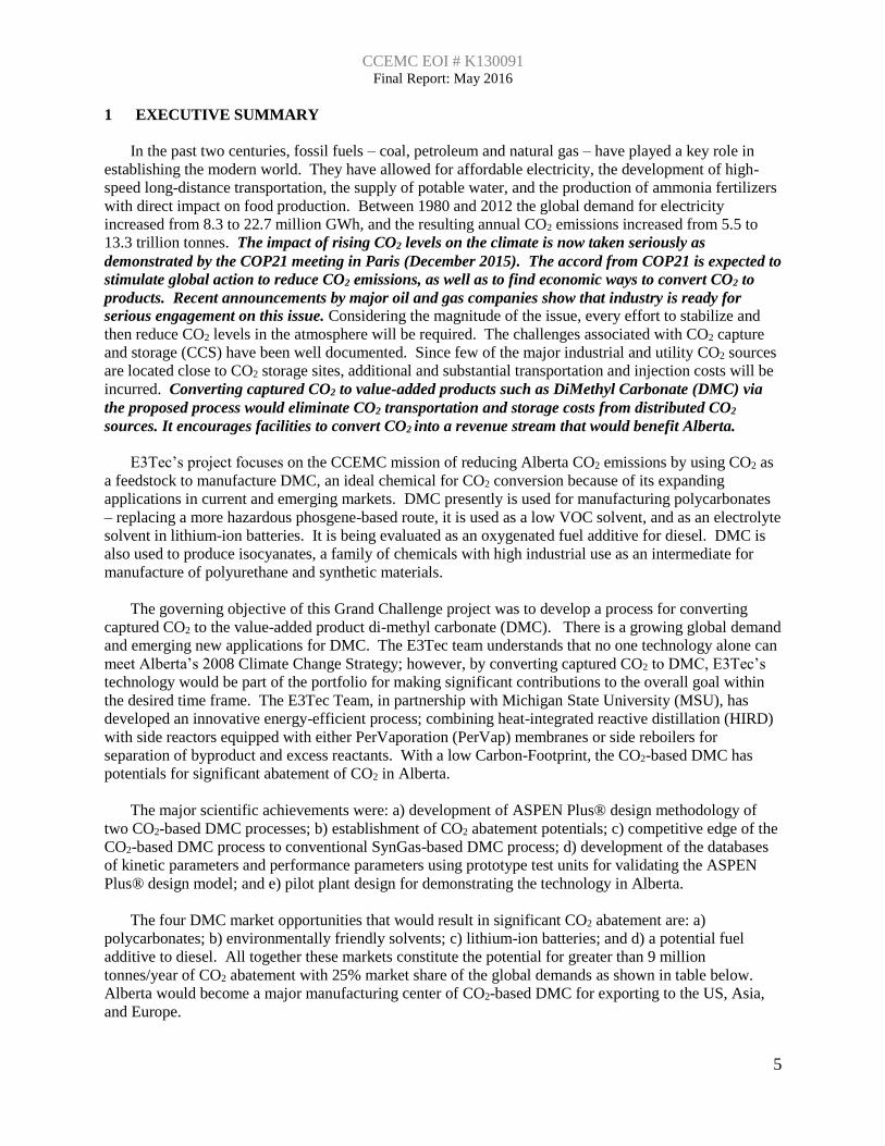
3.2 Technology Development
The technology development goal for CO2 conversion to value-added DMC was to advance the
Technology Readiness Level (TRL) from concept level to pilot plant demonstration. E3Tec is pursuing a
Heat Integrated Reactive Distillation (HIRD) process for conversion of captured CO2 to DMC using two
separate chemical pathways. The HIRD process with side reactors is ideally suited for complex chemical
reactions such as DMC synthesis, whose reaction rate is slow, reversible, and equilibrium controlled.
E3Tec, jointly with Michigan State University (MSU), has developed the HIRD process equipped with
side reactors and pervaporation (PerVap) membranes in pursuit of process intensification and high-levels
of energy efficiency. The Team contends that either technology will have a disruptive impact on global
DMC production, leading to a transformative shift from net CO2 generation to net CO2 utilization.
E3Tec’s prototype Differential Kinetic Test Unit (DKTU) covered by US Patent 9,222,924 B1
(December, 2015), ASPEN Plus® process models, pilot-scale tests at MSU and ASPEN Plus® cost
analysis all provide a strong design basis for scaling the process using the E3Tec’s design methodology
illustrated in Figure 3-3.
The process of CO2 conversion to DMC has been advanced to TRL 5: Laboratory Testing of an
Integrated/Semi-Integrated System: System component and/or process validation in relevant
environment. In the Round 2 project, it will be further advanced to TRL 7: Integrated Pilot System
Demonstration: System/process prototype demonstration in an operational environment meeting some
criteria of TRL 8: System Incorporated in Commercial Design. E3Tec team has applied these TRL
guidelines and the industrial “Stage-Gate” decision-making process at each development stage to a
number of previous projects. This will ensure that the commercialization path will remain as short as
possible and is an important technology edge over other Grand Challenge projects for CO2 conversion to
value-added products.
7 2015 Market Research Report on Global Dimethyl Carbonate (DMC) Industry – Table of Contents.
CCEMC EOI # K130091 Final Report: May 2016
16
Figure 3-3: Schematic diagram of scaling the catalytic process from lab to commercial plants.
3.3 Experimental Procedures and Methodology
Two major project tasks fall under this category - Task 3 of Experimental Determination of Kinetic
Parameters and performance of PerVaporization (PerVap) membranes and Task 6 of Validation Tests
with Pilot Plant. A discuss of each of these is contained in their respective section below.
3.3.1 Kinetic Tests
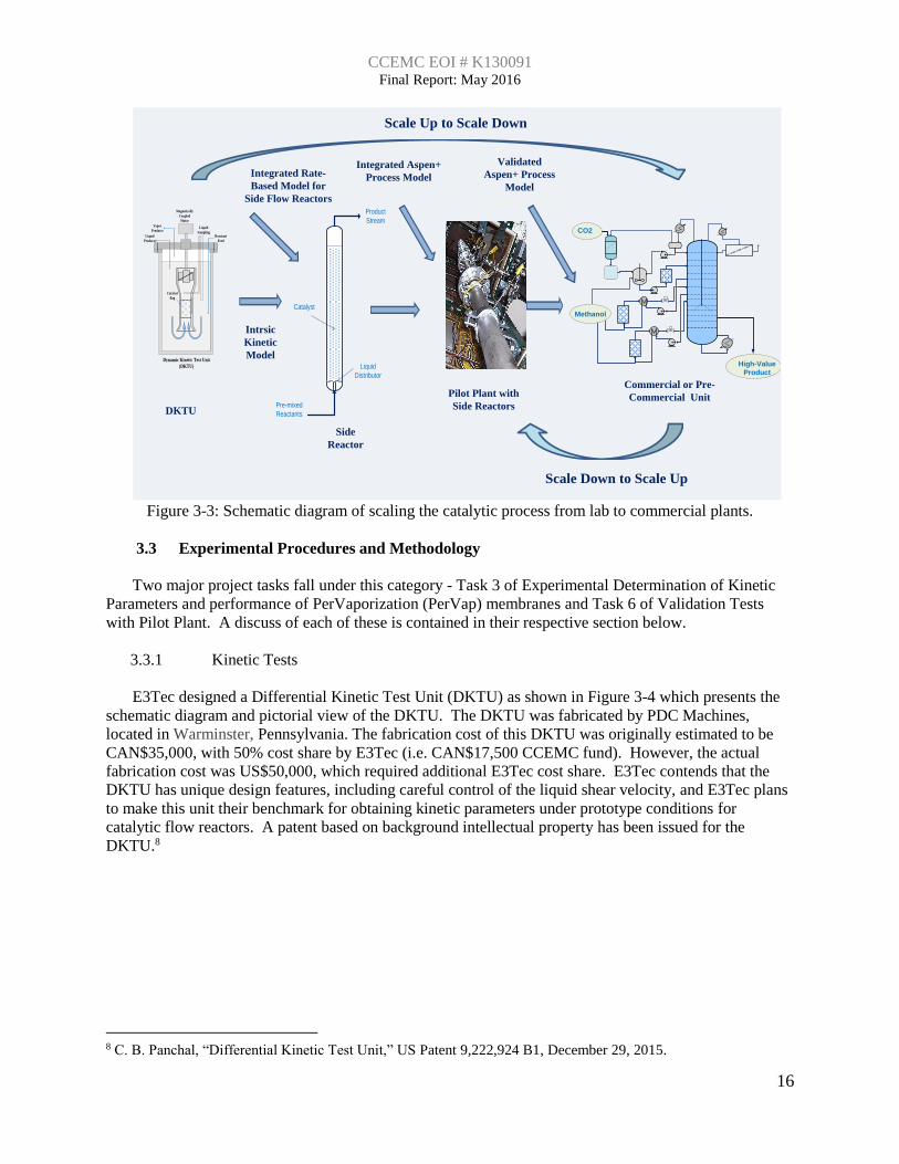
E3Tec designed a Differential Kinetic Test Unit (DKTU) as shown in Figure 3-4 which presents the
schematic diagram and pictorial view of the DKTU. The DKTU was fabricated by PDC Machines,
located in Warminster, Pennsylvania. The fabrication cost of this DKTU was originally estimated to be
CAN$35,000, with 50% cost share by E3Tec (i.e. CAN$17,500 CCEMC fund). However, the actual
fabrication cost was US$50,000, which required additional E3Tec cost share. E3Tec contends that the
DKTU has unique design features, including careful control of the liquid shear velocity, and E3Tec plans
to make this unit their benchmark for obtaining kinetic parameters under prototype conditions for
catalytic flow reactors. A patent based on background intellectual property has been issued for the
DKTU.8
8 C. B. Panchal, “Differential Kinetic Test Unit,” US Patent 9,222,924 B1, December 29, 2015.
Intrsic
Kinetic
Model
Integrated Aspen+
Process Model
Pilot Plant with
Side Reactors
Commercial or Pre-
Commercial Unit
Integrated Rate-
Based Model for
Side Flow Reactors
Reactant
Feed
Vapor
Products
Liquid
Products
Catalyst
Bag
Magnetically
Coupled
Motor
Liquid
Sampling
Dynamic Kinetic Test Unit
(DKTU)
Validated
Aspen+ Process
Model
DKTU
Side
Reactor
Pre-mixed
Reactants
Product
Stream
Liquid
Distributor
Catalyst
Scale Up to Scale Down
Scale Down to Scale Up
CO2
High-Value
Product
Methanol
CCEMC EOI # K130091 Final Report: May 2016
17
Figure 3-4: Schematic diagram and pictorial view of the DKTU.
The first reaction of urea with methanol to form methyl carbamate (MC) is relatively fast and does
not require catalyst. Therefore, the focus of kinetic studies was on the second reaction of MC with
methanol to form DMC, which is slow and reversible. Furthermore, other irreversible reactions are
possible during this reaction step that form byproducts which will affect the overall process C-Footprint.
This task focused on evaluating catalysts reported in the literature based upon Zn, La, Pb, Ca, Mg, Zr, and
Sn.9 ZnO was found to be the most selective catalyst in converting MC to DMC.
Several catalysts based on ZnO have been prepared for the kinetic studies; the procedures followed
below are generally taken from those reported in the literature.
ZnO/Al2O3: Initially, ZnO supported on γ-Al2O3 was prepared by depositing Zn(NO3)2 onto the alumina
by incipient wetness followed by drying and calcining in air at 500oC.
Zn/Urea complex: Zinc oxide was mixed with urea in a round-bottomed flask (with a condenser) and
heated to 150°C. At this temperature, the contents became a milky liquid. The solution was mixed for 40
minutes at 150°C. Upon cooling, the solution became a solid.
ZnFe2O4: An aqueous solution of Zn(NO3)3 and Fe(NO3)3 was added drop-wise to an aqueous solution of
(NH4)2CO3. An ammonia solution was used to maintain the solution pH= 8. The solution was then aged
overnight and the precipitate washed, dried, and calcined in air at 500oC. Procedures were followed from
Wang et al.8.
Over 30 batch-scale tests were conducted using this array of catalysts to replicate the results reported
in the literature and identify the strengths and weaknesses of each. As a result of the extensive work
developing and studying these heterogeneous catalysts based upon ZnO, it was determined that the best
catalyst from the list above was ZnO by itself. Unfortunately, during the studies with ZnO alone, it was
determined that the catalyst was sparingly soluble in the reaction medium. Hence, process modifications
would be required to handle a homogeneous rather than a heterogeneous catalyst. With the efforts
9 Wang et al. Catalysis Communications 11 (2010) 430-433
Magnetically Coupled
Motor
Catalyst Bag
Themmowell
¼” Drain
Coolant Air In
Coolant Air Out
Purge Connected to Reflux
Condenser
Thermowell
Pressure Gage 500 psi
Liquid Feed/Sample
Vapor Sample
Liquid Sample from Flow Tube
Liquid Sample
6.50
4 ½”
2 “
Top Flange
Seven ports with ¼” Swagelok Fittings
plus thermowell for mounting flow tube.
Band Heater with
Temperature Cotrol
3/4 “

CCEMC EOI # K130091 Final Report: May 2016
18
required to modify the process, the E3Tec team has effectively expanded its process technology to include
both types of catalyst.
Reactive distillation using side reactors provides a reliable design approach that enables the control of
the DMC residence time over the catalyst so that degradation and undesired byproduct formation may be
minimized. This can be accomplished by operating the side reactors at temperatures and pressures
differing from the column temperatures and pressures, which are governed by separation. Better control
over DMC-catalyst contact times can also be achieved by isolating the catalyst to the side reactors and
using the distillation column solely for purification. ASPEN Plus® process analysis comparing
conventional reactive distillation with E3Tec’s integrated side reactor technology was performed so that
the best competitive alternative may be developed. E3Tec’s original process was based on heterogeneous
catalyst in side reactors with DMC/Ammonia product and excess methanol separated after each side
reactor. In light of these experimental results, the process was modified to recirculate the homogenous,
sparingly soluble “ZnO-Urea Complex Catalyst” to the side reactors while maintaining optimum
residence time in each side reactor to minimize undesired byproduct formation. These byproducts are
further decreased by removing DMC from the remaining reactants in either the distillation or
pervaporation units.
As a final step in this task a batch kinetic study was conducted on the effect of the ZnO catalyst
loading and temperature on the reaction between urea and methanol. Six experiments at temperatures
covering 80-120°C and 0.3-1.2 wt% Zn were conducted. Parameters from the detailed kinetic rate
expression were determined from regression of this data using ASPEN Plus®. This expression was then
used to refine the ASPEN Plus® process analysis for the pilot-plant and commercial plant.
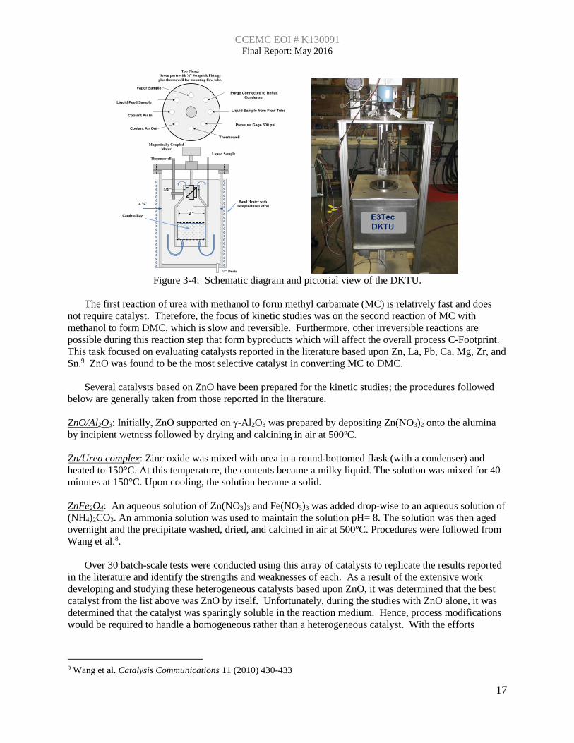
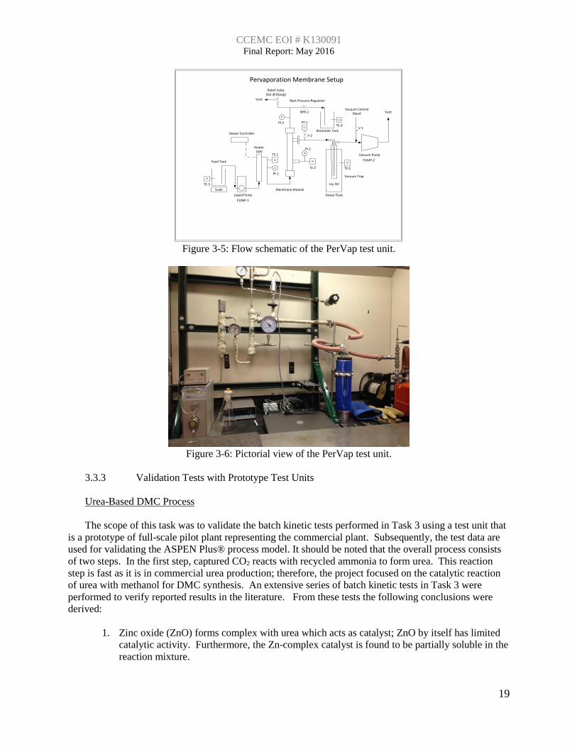
3.3.2 PerVap Performance Tests
Gas Technology Institute (GTI) was the lead for this Task 4. GTI procured the equipment, and
constructed the PerVap test rig. Subsequently, GTI completed 13 PerVap tests using DMC/methanol
azeotropic mixtures. The performance data from these tests were converted to an EXCEL model10 and
are now incorporated into the ASPEN Plus® process design model. Figures 3-5 and 3-6 present the
schematic diagram and pictorial view, respectively. Two types of membranes were tested for their
separation efficiency when fed both a liquid and a vapor DMC/methanol azeotropic mixture. The mass
flux of the methanol permeate was measured as kg/s per m2 of membrane area (DMC remains with the
retentate):
Ceramic tubular membranes are more expensive; however, they can be operated at high
temperature, yielding high mass flux.
Polymeric hollow-fiber membranes are cheaper and exhibit relatively high flux at low
temperatures, but often with lower separation efficiency and possible compatibility problems.
The initial tests employing the polymeric hollow fiber membrane found that the hollow fiber assembly
was not compatible with DMC and methanol. Therefore, further tests were conducted using the ceramic
membrane obtained from Pervatech™.
10 Lovasz A., P. Mizsey, Z. Fonyo; "Methodology for parameter estimation of modelling of pervaporation in flow-
sheeting environment," Chem.Eng.J. 133 (2007) 219–227.
CCEMC EOI # K130091 Final Report: May 2016
19
Figure 3-5: Flow schematic of the PerVap test unit.
Figure 3-6: Pictorial view of the PerVap test unit.
3.3.3 Validation Tests with Prototype Test Units
Urea-Based DMC Process
The scope of this task was to validate the batch kinetic tests performed in Task 3 using a test unit that
is a prototype of full-scale pilot plant representing the commercial plant. Subsequently, the test data are
used for validating the ASPEN Plus® process model. It should be noted that the overall process consists
of two steps. In the first step, captured CO2 reacts with recycled ammonia to form urea. This reaction
step is fast as it is in commercial urea production; therefore, the project focused on the catalytic reaction
of urea with methanol for DMC synthesis. An extensive series of batch kinetic tests in Task 3 were
performed to verify reported results in the literature. From these tests the following conclusions were
derived:
1. Zinc oxide (ZnO) forms complex with urea which acts as catalyst; ZnO by itself has limited
catalytic activity. Furthermore, the Zn-complex catalyst is found to be partially soluble in the
reaction mixture.
Pervaporation Membrane Setup
Scale
Liquid Pump
Heater 1kW
Heater Controller
Feed Tank
Retantate Tank
Vacuum Pump
Dewar Flask
Vacuum Trap
Membrane Module
Back Pressure Regulator
Vent
TE
PI
PI
TE
PT
TE
TE
TE
Liq. N2
PI
Vent
Vacuum Control Bleed
TE-1
PT-1
PI-1
PUMP-2
BPR-1
V-1
TE-2
TE-4
TE-3
TE-5
PI-2
PI-3
PUMP-1
V-2
Relief Valve (Set @35psig)

CCEMC EOI # K130091 Final Report: May 2016
20
2. Fixing ZnO on aluminum oxide - alumina (Al2O3) to make it a heterogeneous catalyst showed
limited activity.
3. An intermediate product, methyl carbamate (MC) is first formed by replacing one of the two
amine (ammonia) groups by a methyl oxide group. MC then further reacts with methanol to
form DMC by replacing the second amine (ammonia) group.
4. In the batch kinetic tests the DMC formed reacts and is decomposed in the presence of the
Zn-complex catalyst and through further reaction with MC to form a side product N-methyl
methyl carbamate (NMMC).
5. As suspected, the batch kinetics showed considerable inconsistency with the literature data
that was used to develop the original urea-based process. However, the present database of
extensive kinetic tests provides a reliable basis for the improved commercial DMC process.
The batch kinetics, as described above, presented some challenges to the process concept that was
designed for a heterogeneous catalyst. Redesign to include the homogeneous catalyst and address the
issues relating to the undesired reactions led to the incorporation of a side reactor recirculation flow loop.
There are two basic requirements for this approach: a) effective use of homogeneous Zn-complex
catalyst; and b) efficient separation of DMC as it is formed to minimize side reaction(s) and possible
decomposition that would reduce DMC yield adversely affecting the C-Footprint.
The ASPEN Plus® process analysis showed that the proposed initial design employing reactive
distillation using side reactors with heterogeneous catalysts can be equally effective using this
recirculation flow loop with a homogeneous catalyst. Therefore, a prototype test unit was designed as
shown in Figure 3-7. The recirculation flow loop represents one of the side reactors of the pilot plant and
full process, as discussed in next section on pilot plant design. The catalyst reaction mixture is
recirculated through the side reactor and DMC, methanol, and a limited amount of MC are separated from
the reactor product stream by vaporization. The reactant rich mixture along with homogeneous catalyst is
then recirculated and a fresh feed of urea, MC and methanol is mixed with the recirculating reactant flow
and fed to the side reactor. Samples were taken at proper intervals during the test period. The primary
focus was to determine the effects of temperature and feed composition on the relative rates of conversion
and selectivity of DMC in the product stream. The predicted overall conversion of MC and urea was
reasonable for a single side reactor and recirculation loop. Furthermore, by separating DMC from the
recirculating flow stream, further reactions are reduced yielding high selectivity of DMC in the product
stream. The batch kinetic tests showed low selectivity in the closed environment of a batch reactor.
Figure 3-7: Process diagram of the prototype test unit for the urea based process.
Feed:
MC-
Methanol
P
T
T
Product P
P
2" Side
Reactor
T
T
T
T
T
NH3
Purge
Sr-2
Pump
P
SR-3
Pump
Chilled
Water
FM
T
T
T
T
T
T
Heater
FM
Reboiler
Sample
Point
Sample
Point
Sample
Point
Sample Point with
Cooling Device
attached to Sample
Bottle
Citric Acid
NH3 Trap
Vent
Sample
Point
Capillary
Equilizer
Line
T
Liquid Purge
Level
Controller
Flask to
Prevent
Backflow
P
Feed Line for
flushing
during shut
down Air-
Cooled
P
V/L
Separatio
n

CCEMC EOI # K130091 Final Report: May 2016
21
Ethylene Oxide-Based DMC Process
The ethylene-oxide based DMC process uses commercially available heterogeneous catalysts.
Extensive batch kinetic tests were performed under DOE SBIR Phase I project, and the kinetic parameters
from these tests were used to design the test matrix for CCEMC experiments with a smaller-scale
prototype test unit. This leveraging effort was beneficial to the CCEMC project. The test results and
analysis are carefully documented to avoid conflicts between the two projects, while taking advantages of
both projects.
The prototype tests were performed using a stand-alone side reactor, as shown in Figure 3-8. The
reaction between CO2 and ethylene-oxide is known and commercially practiced for synthesizing ethylene
carbonate (EC). Handling of ethylene oxide requires additional safety precautions; therefore, tests were
performed using EC. Initial tests were performed using a larger side reactor, 5 cm diameter and 91 cm
height. Subsequent tests were performed using a smaller side reactor to evaluate the scale up
methodologies and to baseline the smaller unit for future experiments with this system in Round 2. The
smaller side reactor was 1 cm diameter and 8 cm height. The two series of tests with different sizes
validated the ASPEN Plus® process scale method.
Figure 3-8: Process diagram of the prototype test unit for the ethylene oxide based process.
3.4 Modeling Details
3.4.1 Kinetic Model
Kinetic Models (urea-based process): A power-law based kinetic model was developed for the
conversion reactions of MC and DMC and linked into the ASPEN Plus® model. These kinetics models
permitted E3Tec to use ASPEN Plus® to optimize the process configuration for the commercial plant
based upon CAPEX/OPEX. The model assumes that the reactions are: 1) first order with respect to each
reactant concentration; and 2) proportional to the reactor catalyst loading (Wcat in units of gm Zn/gm
reaction solution). The ZnO-Urea Complex catalyst used in these studies contains 42 wt% Zn as
measured by ICP analysis; the theoretical Zn loading in the ZnO-Urea Complex catalyst is 35 wt%,
indicating that our Zn-Urea Complex contains some partially complexed zinc.
The general rate equation for the batch reactor is:
-dCi/dt = -ri = k∙Wcat∙Ci
Concentration of the reacting species “i” can be represented as Ci = Ci,o (1-xi), where xi is fractional
conversion of the reacting species as determined by GC analysis in real time during the test. The above
T
Product
Feed:
EC-Methanol
P
2" by 1 meter
Side Reactor
with A-21
Resin
T
Purge
Metering
pump
P
Chilled
Water
FM
T
T
T
T
T
T
T
T
Electric
Pipe
Heater
T Sample
Point
Sample
Point
Sample
Point

CCEMC EOI # K130091 Final Report: May 2016
22
rate equation can be separated and integrated over the reaction time at the reaction temperature to give the
following expression:
-ln[(1-xi)/(1-xi,o)] = k∙Wcat∙t
Where reaction constant k (T) = ko,i exp(Ea/(RT) and
ko,i = pre-exponent reaction constant for reacting species i
Ea,i = Energy of activation, J/kmol
R = Gas constant, J/kmol K
T = Reaction temperature, K
Here xi,o is the conversion of the reacting species at the point in time (defined as t=0) that the reaction
mixture reaches the specified reaction temperature. It was observed that both the forward and reverse
reaction took place while the reactor was heating up to the reaction temperature. This approach was
employed to obtain the kinetic parameters for both the desired and undesired reactions.
Kinetic Models (ethylene oxide-based process): An approach similar to the one described above for
the urea-based process was undertaken for the ethylene-oxide-based process during the SBIR Phase I
project. Small-scale batch kinetic studies were conducted and a simplified power-law model
incorporating catalyst loading was developed. This model was then employed to generate a test matrix
for large-scale pilot studies conducted with a stand-alone packed-bed reactor. The Amberlyst A-21
catalyst showed the most promise for the reaction of EC and methanol to form DMC. A few other
catalysts were screened during the study, but the kinetic models were all developed on data collected
using the A-21 catalyst.
As expected, the data collected from the stand-alone packed-bed reactor showed improvement in
catalyst performance over those obtained during the batch kinetic studies. Because of the density
differences between catalyst and solution, it is believed that contact between the two in the batch reactors
was not representative of that occurring within the packed-bed reactor. So, the packed-bed reactor data
then were regressed using the plug-flow reactor model in ASPEN Plus®. The rate constants were
determined by numerical integration of all species balances along the length of the packed-bed reactor
shown in Figure 3. The packed catalyst bed porosity was assumed to be 0.485 based upon our previous
experience with other Amberlyst catalysts and the catalyst particle density was assumed to be 1.2 g/cc.
For each of the packed-bed experiments, a total of four rate constants were fit simultaneously for the
reactions:
Ethylene Carbonate + Methanol → Hydroxyethyl Methyl Carbonate (HEMC) (Rxn 1)
Hydroxyethyl Methyl Carbonate → Ethylene Carbonate + Methanol (Rxn 2)
Hydroxyethyl Methyl Carbonate + Methanol → DMC + Ethylene Glycol (Rxn 3)
DMC + Ethylene Glycol → Hydroxyethyl Methyl Carbonate + Methanol (Rxn 4)
The rate constant values obtained for each reaction were then fit to an Arrhenius relation to determine
the temperature effect. The ASPEN Plus® model with these expressions for the reaction rate constants
were then used to generate a test matrix of conditions for the smaller-scale packed-bed reactor.
3.4.2 ASPEN Plus® Process Models
E3Tec has developed a portfolio of ASPEN Plus® process models for an integrated system of
distillation, a series of side reactors, PerVap membranes and/or other separation units. The process
models are based on E3Tec’s design methodology that effectively scales the laboratory kinetic parameters
for side reactors to the full process with a high-degree of certainty. The ASPEN Plus® models for both
DMC processes are validated using kinetic data and PerVap performance parameters. The process

CCEMC EOI # K130091 Final Report: May 2016
23
analysis for the urea-based process is based on a commercial-scale plant with 51 kTA DMC production
capacities. The ethylene-oxide based process analysis is based upon a commercial-scale plant of similar
DMC production capacities. The purpose of the ASPEN Plus® process analysis is to develop a rigorous
description of an energy and capital efficient commercial-scale DMC process based upon the best
information currently available. This effort, while initially time-consuming, helps focus the process
development efforts on improving the quality of the information that would most affect the process
description. As the quality of the information (e.g. kinetic parameters, PerVap performance parameters,
etc.) is improved, the process analysis revises the rigorous commercial process description - identifying a
new set of information whose quality would most affect it. The rigorous process model currently contains
the kinetic parameters from lab-scale studies that are subsequently validated with performance parameters
from prototype pilot-scale tests.
The process analysis plays a significant role in the pilot-scale validation through generation of the test
matrix to be conducted at this scale. A separate rigorous test unit process model is constructed and a
comprehensive sensitivity study is conducted. The objective of this study is to identify the operating
regions that are most affected by those parameters whose quality has been improved through the lab-scale
studies. By integrating rigorous process descriptions into the development process, E3Tec’s
methodologies are able to rapidly commercialize a chemical process; allowing those developing the
process to move to larger scale demonstrations with confidence.
3.4.3 Integration of DMC Process
E3Tec is pursuing integrating the DMC process with the following industry sectors.
a. Utility and process industry with CO2 sources.
b. Methanol manufacturing plants; conventional SynGas as well as biomass or renewable
energy based methanol plants.
c. Ethylene chain manufacturing plants; ethylene oxide and ethylene glycol.
An integrated process of CO2 capture and conversion to DMC is expected to have significant techno-
economic merits over separate CO2 capture and conversion processes. Heat integration between the two
processes is expected to have a lower C-Footprint, specifically because CO2 does not have to be liquefied
or compressed for transportation. E3Tec is pursuing collaboration with Illinois Sustainability Technology
Center (ISTC) for an integrated plant. Methanol is the primary feedstock in addition to captured CO2;
therefore, it is logical to integrate the DMC process with the methanol plants. The conventional SynGas
process has high C-Footprint; however, the integrated process will utilize CO2 from the SMR process
used for producing hydrogen needed in the methanol process. So, integrating the CO2 source and
methanol as feedstock, will have significantly lower C-Footprint than separate processes. E3Tec intends
to pursue such an integrated process with the Methanex plant in Alberta. Alberta has a major producer of
ethylene and its derivatives.11 The production capacity of ethylene and ethylene glycol are about 4,000
and 800 thousand tonnes/year. Apparently, there is excess capacity of ethylene oxide, which can be
utilized for ethylene oxide based DMC process.
Integrating with CO2 Sources: The proposed process can be integrated with the following three
primary CO2 sources: 1) Gas Turbine Combined Cycle (GTCC) – industry and utility scale; 2) Steam
Methane Reforming (SMR) for production of hydrogen; and 3) coal utility plants with installed CO2
capture system. Table 2 presents a summary of CO2 recovery from these three sources. These three
sources of CO2 are relevant to Alberta. Presently, about 60% of Alberta’s power generation is coal-based.
11 Canadian Energy Research Institute, CERI Report “Examining the Expansion Potentials of Petrochemical in Canada, Study no
153, August (2015).

CCEMC EOI # K130091 Final Report: May 2016
24
However, Alberta would very likely follow a similar path to the US and convert many of these to GTCC
in the foreseeable future.
GTCC Flue Gas Amine Absorber-Stripper for CO2 Capture: Gas Turbine Combined Cycle (GTCC)
is expected to be a major source of power generation new capacity additions at the utility as well as the
industrial level. In parallel, some industry sectors use Co-Gen provided they can optimally balance power
and steam demands. Conditioned flue gas with low levels of Oxygen, NOx and SOx (<15 ppmv) is sent to
an absorber tower where it is contacted with “lean” amine feed consisting of an aqueous solution of
alkanolamines, which react with CO2 to form the bicarbonate (HCO3-) or carbamate ions (RNHCO2-).
One system using amines for flue-gas CO2 recovery that has been demonstrated on a commercial-scale is
Fluor’s Econamine® process.
SMR Amine Absorber-Stripper for CO2 Capture: The SMR process is primarily used for hydrogen
and syngas (H2 + CO) production. Alberta industries include methanol plants, oil-sand processing plants,
and refineries. A typical SMR amine process produces high-purity CO2 (99.8%) at a rate of 8.32 kg/ kg
of H2. CO2 generation from thermal energy required for the SMR process is 1.96 kg/kg H2. In Steam
Methane Reforming of hydrocarbon feeds, natural gas is converted to high purity hydrogen and for the
bulk of existing capacity, a CO2 side product through the overall reaction: CH4 + 2H2O → CO2 + 3H2.
Amines can be used for recovering this CO2; however, in this case the recovery tower does not have to
handle even traces of oxygen. Only moisture and traces of inert gases are present in the CO2 product.
CO2 Capture from coal utility plant: There have been pilot tests of many flue gas CO2 capture
systems. However, one of the few systems to be demonstrated at a commercial scale is Fluor
Economine®. Amine recovery of CO2 from either flue gas has an energy cost around 0.81 kW/kg CO2
and it could be expected that the proprietary mix of amines used by Fluor should be better than this.12
There is a disadvantage for flue gas capture in that the presence of oxygen degrades the costly amines,
hence recovery of flue gas will be at a disadvantage compared to recovery from an oxygen-free process
stream such as those from hydrogen plants. The new generation of CO2 capture technology is expected to
deliver 90 percent CO2 capture at 99% purity and take other emissions such as SOx and NOx to near-zero
levels, as indicate din Table 3-1.
Table 3-1: Characterization of CO2 from three sources.
Source Flue-Gas Amine SMR-Amine Captured CO2 from Coal
Plants
Product Electricity Hydrogen Electricity
Temperature Ambient Ambient Ambient
Pressure 2.6 bar 14 bar Atmospheric
H2O 1.8 % Trace
N2 0.6% None
O2 None None Trace
CO2 97.6% 99.8% 99.5%
Integration with Methanol Plants: E3Tec is actively pursuing integration of the DMC plant with three
types of methanol production plants in Alberta: a) conventional SynGas based plant by Methanex; b)
municipal waste to methanol plant by Enerkem; and c) methanol as by-product from the forest products,
pulp & paper industry (e.g. ALPAC).
12 Doctor, R.D. , Future of CCS Adoption at Existing PC Plants Economic Comparison of CO2 Capture and Sequestration from Amines and
Oxyfuels, Argonne Report, ANL/ESD/12-9 (Dec. 29, 2011).

CCEMC EOI # K130091 Final Report: May 2016
25
For the Kraft pulp process, the amount of methanol produced at the digester is about 10 kg per tonne
of pulp. In Alberta, Dishawa-Marubeni International has a plant at Peace River with name-plate
production capacity of 400 kTA (thousand tonnes/yr). So, the methanol produced as by-product for this
plant is on the order of 4 kTA. This corresponds to the feed methanol requirements of a 5.6 kTA DMC
production case using the E3Tec process technology. Since methanol is produced as a by-product of the
pulp process derived from forest products, the resulting CO2 consumption would be 3.64 kTA as per the
C-Footprint analysis.
Enerkem Alberta Biofuels LP, Edmonton (AB) expects to produce about 38 million liters of methanol
per year from municipal waste, which corresponds to 30 kTA. Again CO2 equivalent emission (including
methane release avoidance from landfill) from the municipal waste to methanol process is relatively
small, if not negative (net consumption). Therefore, the resulting CO2 consumption would be 27.3 kTA,
if the DMC plant is integrated with the Enerkem or an equivalent plant producing methanol from organic
municipal waste. With an aggressive technology development and business strategy, this production is
achievable by 2020. As per Alberta’s 2008 Climate Change Strategy, the target CO2 reduction is 50
megatonnes/yr (MTA) total with about 9.25 MTA from greening energy production wedge, which
includes renewable energy and CO2 consumption as feedstock. The DMC process or one of the other
similar processes alone will not meet this target; however, it can be part of the portfolio to meet the long
term goal. Alternatively, with the DMC production using bio-based methanol established, industry in
Alberta will be encouraged to expand the production of DMC using methanol from the Methanex facility
in Medicine Hat, Alberta which operates a 600 kTA plant and markets methanol throughout North
America. E3Tec’s target is to achieve 1,000 kTA DMC production using this new technology in Alberta
by 2030 with a resulting CO2 consumption of 0.29 MTA.
Integration with Ethylene Plants: E3Tec will also pursue DMC production using ethylene oxide
(EtO) as feedstock based on E3Tec’s US/DOE SBIR Phase I project. This process can be integrated with
an ethylene oxide/ethylene glycol plant located in Alberta. Shell Chemicals has 450 kTA ethylene glycol
plant using Shell’s process OMEGA (Only Mono-Ethylene Glycol Advantage) in Scotfield, Alberta.
E3Tec’s ethylene oxide to DMC process produces mono-ethylene glycol selectively, E3Tec will pursue a
partnership with Shell Chemicals for future expansion of mono-ethylene glycol in Alberta to meet the
expanding global demand.
The next strategic question to focus on is what incentives would be necessary for industry and
investors to locate DMC plants in Alberta. Note that this question also applies to other technologies for
converting CO2 to high-value products. In the case for DMC, the strategic points to be considered are: a)
the DMC global market is expanding, creating an economic opportunity for a competitive technology; b)
Alberta is strategically positioned and currently transports chemicals to both Asian and US markets; c) the
US could be a major market for more than 1,000 kTA DMC by replacing phosgene based polycarbonate
production; d) the Ethylene Oxide (EtO) to DMC process alternative will also benefit from Mono-
Ethylene Glycol (MEG) market growth and interest from the petroleum industry in supporting DMC as a
fuel additive; e) there is a positive image for a company consuming CO2 to make high-value products; f)
DMC can be more easily transported than other CO2 derived products (e.g. inorganic carbonates); g)
either of the E3Tec process alternatives can be commercialized in a short period of time; h) linking the
DMC process with methanol production from Pulp & Paper industry located in Alberta and other parts of
Canada as well as to Enerkem’s municipal organic waste to methanol plant results in an overall process
with a very low C-Footprint; and i) DMC production will attract high-tech, end-user industries to Alberta
such as manufacturers of Lithium-ion batteries and polycarbonates.
In summary, the value of E3Tec’s DMC process technology is that it can be readily integrated with
plants having sources of captured CO2 and with plants having feed sources of methanol. E3Tec is also

CCEMC EOI # K130091 Final Report: May 2016
26
developing a process with US/DOE SBIR Phase I grant for conversion of captured CO2 to alkyl carbonate
(in this case DMC) using ethylene oxide as feed stock and co-producing mono-ethylene glycol. This
process can be integrated with a petro-chemical plant having both sources of captured CO2 and ethylene
oxide. This ethylene-oxide based DMC process will be included in the next phase of the CCEMC project.
In Round 2, E3Tec will interact with the relevant industries to establish techno-economic merits of
locating DMC production plants in Alberta based on the emerging global demands for DMC.
3.5 Results and Discussion
3.5.1 Kinetic Parameters
Urea-Based Chemistry: As mentioned previously, ZnO forms an organometallic complex with urea
that is sparingly soluble in methanol. Further experiments showed that ZnO in its free form or supported
on -alumina (Al2O3) has limited activity for conversion of MC to DMC. Rather, the ZnO-urea complex
formed in-situ during reaction acts as the active catalyst. Further kinetic tests have been conducted using
the ZnO-urea complex, and an initial set of kinetic parameters was obtained.
Experiments have been carried out to characterize the kinetics of methyl carbamate conversion to
dimethyl carbonate. The focus of these initial experiments has been on the conversion rate of methyl
carbamate (MC), and on the decomposition rate of dimethyl carbonate (DMC). These experiments were
conducted at temperatures of 130-170oC using 0.25 – 2.0 wt% of zinc in reaction solution in the form of
“Zn-Urea Complex.” Molar ratios of 10:1 and 20:1 MeOH:MC and a ratio of 28:1 MeOH:DMC were
used in initial experiments.
The primary desired reactions are:
Urea + MeOH → MC + NH3
MC + MeOH → DMC + NH3
Decomposition and/or further reaction of DMC has been characterized as well. It is postulated that
these reactions occur via one or more of the reaction pathways listed below. The first of these pathways
includes the formation of N-methyl methyl carbamate (NMMC) in the presence of “ZnO-Urea Complex”
catalyst.
DMC + MC → NMMC + MeOH + CO2 (reference from Wang paper)
DMC → Dimethyl Ether + CO2 (in presence of catalyst)
Without the catalyst there was no degradation of DMC, even when exposed to high temperatures of
190oC for several hours. Since there was a question as to whether NMMC was formed via methylation by
DMC or methanol, experiments were run with MC and methanol in the presence of the catalyst. These
studies provide evidence that NMMC is only formed in measurable quantities after some MC is converted
to DMC.
Approximately 60 batch experiments were conducted in order to determine the kinetic parameters for
all four reactions listed previously. The reaction rate model for this system is:
𝑑[𝑀𝐶]
𝑑𝑡 = −𝑘1[𝑀𝐶][𝑀𝑒𝑂𝐻] + 𝑘2[𝑈𝑟𝑒𝑎][𝑀𝑒𝑂𝐻] − 𝑘4[𝐷𝑀𝐶][𝑀𝐶]
𝑑[𝑈𝑟𝑒𝑎]
𝑑𝑡 = −𝑘2[𝑈𝑟𝑒𝑎][𝑀𝑒𝑂𝐻]

CCEMC EOI # K130091 Final Report: May 2016
27
𝑑[𝐷𝑀𝐶]
𝑑𝑡 = 𝑘1[𝑀𝐶][𝑀𝑒𝑂𝐻] − 𝑘3[𝐷𝑀𝐶] − 𝑘4[𝐷𝑀𝐶][𝑀𝐶]
𝑑[𝑁𝑀𝑀𝐶]
𝑑𝑡= 𝑘4[𝐷𝑀𝐶][𝑀𝐶]
The effects of temperature and catalyst loading on the reaction rate parameters (i.e. k1 through k4)
were determined through regression of each individual experiment.
Ethylene Oxide-Based Chemistry
The reactions to produce DMC via the ethylene oxide pathway are as follows:
Ethylene Oxide + CO2 → Ethylene Carbonate
Ethylene Carbonate + Methanol ↔ Hydroxyethyl Methyl Carbonate
Hydroxyethyl Methyl Carbonate + Methanol ↔ DMC + MEG
The initial lab-scale batch kinetic work was performed under DOE/SBIR Phase I. In order to
maintain the confidentiality of the two projects the details of the kinetic parameters are not presented in
this report. However, the kinetic parameters are used in the ASPEN Plus® process, which is used for
both processes. The work covering the pilot-scale work was supported by both this project and
DOE/SBIR Phase I and so only results of the pilot-scale work are included here.
Since the first reaction to produce ethylene carbonate is commercially practiced, and special safety
procedures are required for handling ethylene oxide, the kinetics of this reaction were not studied.
Production of DMC from ethylene carbonate involves two reversible reactions. The first reaction step to
produce Hydroxyethyl Methyl Carbonate (HEMC) is rapid and quickly equilibrates. The second reaction
step to produce DMC and MEG is slow. Ion Exchange Resins Amberlyst A-21 and A-26 were used to
catalyze these reactions during the initial screening studies. The A-21 resin was used for the pilot-scale
work.
𝑑[𝐸𝐶]
𝑑𝑡 = −𝑘1[𝐸𝐶][𝑀𝑒𝑂𝐻] + 𝑘2[𝐻𝐸𝑀𝐶]
𝑑[𝐻𝐸𝑀𝐶]
𝑑𝑡= −𝑘2[𝐻𝐸𝑀𝐶] + 𝑘1[𝐸𝐶][𝑀𝑒𝑂𝐻] − 𝑘3[𝐻𝐸𝑀𝐶][𝑀𝑒𝑂𝐻] + 𝑘4[𝐷𝑀𝐶][𝐸𝐺]
𝑑[𝐷𝑀𝐶]
𝑑𝑡 =
𝑑[𝐸𝐺]
𝑑𝑡= 𝑘3[𝐻𝐸𝑀𝐶][𝑀𝑒𝑂𝐻] − 𝑘4[𝐷𝑀𝐶][𝐸𝐺]
3.5.2 PerVap Performance
Two series of tests were performed. In the first series of tests the feed was maintained in the liquid
phase by operating the membrane at pressures above the bubble point of the azeotrope. The first two tests
were performed at 95ºC and 30 psig pressure, while the remaining tests were performed at 105ºC and 40
psig. The permeate side vacuum was maintained at 20 mbar. The permeate flux was 6.1 kg/hr m2 at 95ºC
and varied between 7.1 and 8.2 kg/hr m2 at 105ºC, respectively. In a second series of tests the
DMC/methanol mixture was fed in the vapor phase to simulate the condition of the overhead stream from
the distillation column. By feeding the mixture in the vapor phase the HIRD process would not require
condensing the overhead stream. The temperature was maintained between 95ºC and 105ºC for all tests,

CCEMC EOI # K130091 Final Report: May 2016
28
except the last two Tests 12 and 13 for which temperature was maintained between 133ºC and 139ºC to
determine the effects of temperature with vapor feed. There were no significant effects of temperature on
flux or selectivity for vapor feed. In two tests, methanol was maintained at a higher concentration that
reduced the flux; however, selectivity increased. For other tests, the permeate flux and selectivity were
lower compared to liquid feed. A trade-off analysis will be performed on the commercial-scale process to
determine whether it is better to condense the overhead to provide liquid feed to PerVap or maintain the
overhead stream in vapor phase. In summary, the PerVap tests were completed as planned and the
performance data are incorporated in the ASPEN Plus® process model.
3.5.3 Prototype Test Results
Urea-Based Process
As a consequence of the leak in the prototype test unit, there was insufficient time remaining in the
project to complete more than three test conditions. However, while the test unit were not sufficiently
long for the compositions in the recirculation loop to reach steady state, the dynamic response of the
membranes and an inferred steady-state permitted partial validation of the kinetic model, and the ASPEN
Plus® simulation model was applied based on quasi-steady state conditions. The compositions at the
inlet and outlet of the reactor were collected. From the model comparisons, the ASPEN Plus® model
predicts the product species distribution within measurement uncertainties. The quality and quantity of
test parameter measurements were deemed adequate for validating the ASPEN Plus® process model.
Additional pilot-plant conditions operated at steady-state with model predictions around the entire system
and its individual components will be performed in Round 2.
Ethylene Oxide-Based Process
Performance tests were conducted using two separate side reactors for validating the scaling up
design methodology; 1) 5-cm by 91-cm and 2) 1-cm by 8-cm. The tests on the larger pilot-scale reactor
were regressed using ASPEN Plus® to determine the kinetic parameter values (k1 through k4) for the
reaction model. These values were then used in an ASPEN Plus® model of the small-scale flow reactor
to validate the model. EC conversions observed for the range of temperatures and flowrates on the small
flow reactor are predicted well by the model, specifically at reaction temperatures of 70ºC and 80ºC
including the effects of flow rates. These results give us the confidence that the model will accurately
predict performance of the reactors on the commercial scale.
3.5.4 Process Analysis
Process analysis remains the project cornerstone and consists of the following elements:
a. Process configuration of HIRD integrated with side reactors, PerVap membrane and auxiliary
equipment.
b. Exploring the ASPEN Plus® process simulation to determine an optimum process configuration
c. Energy analysis to evaluate potential heat integration without significant equipment costs,
specifically heat exchangers and associated pumps.
d. Pilot-plant design, including equipment specifications.
e. Validation of the process model based on kinetic test data and performance parameters from
prototype test units.
The results from the process analysis are discussed in various sections. Therefore, an overview of the
ASPEN Plus® process analysis is described here as it is applied to commercial scale process units.

CCEMC EOI # K130091 Final Report: May 2016
29
ASPEN Plus® flow diagrams shown in this section are for the purpose of understanding the details
incorporated in the process model.
Urea-Based Process Unit
The Urea-based commercial plant process parameters are presented in Table 3-2, along with those for
the alternate ethylene oxide-based process. PerVap membrane performance was evaluated for the
separation of methanol from the DMC/methanol azeotrope. A trade-off analysis was performed with and
without the use of PerVap. The process analysis showed that ammonia released from urea can act as an
entrainer to break the DMC/methanol azeotropic mixture in the urea-based DMC process. As a result,
PerVap may not be required. The two processes with and without PerVap have comparable energy
efficiency; however, the process without PerVap would require a high-degree of heat integration to
achieve the energy efficiency of the process with PerVap already demonstrated. This trade-off analysis
will be continued in Round 2 with the focus on the added CAPEX costs of heat exchangers for heat
integration with and without PerVap. Furthermore, the critical issues of process operation will be
evaluated to assure that the process will operate optimally with minimum side reactions that would reduce
the product yield and adversely affect the C-Footprint.
Ethylene Oxide-Based Process Unit
The ethylene oxide-based process involves two products, which required careful process
configuration for low capital and high-energy efficiency. Various process configurations were evaluated
based on ASPEN Plus® process simulations. Design parameters are presented in Table 3-2 along with
those for the urea-based process. Compared to the urea process, where ammonia can act an entrainer,
PerVap improves the energy efficiency as well as reduces the size of the methanol recovery distillation
column.
Design parameters presented in Table 3-2 provide a summary of the overall mass and energy
balances. Both processes were designed to produce ~50 kTA DMC with corresponding consumption of
CO2, methanol and ethylene oxide. The urea-based process requires makeup for ammonia lost to
byproducts and/or purging. It produces process water that can be recycled by removing traces of urea.
The ethylene oxide-based process produces 0.706 kg MEG / kg of DMC, and forms no side products.
The process analysis as well as the prototype tests validated the production rates. Presently, the 441 kg/hr
is purged for balancing the ASPEN Plus® process analysis. It consists of MEG, EC and intermediate
product, which can be recycled in the process. As a consequence of problems encountered operating the
prototype test unit for the urea-based process, the urea process analysis is based on the literature kinetic
parameters, which do not fully account for byproducts. Obtaining reliable, independent kinetic parameters
from the prototype test unit will permit us to validate the ASPEN Plus® design. This will have high
priority in Round 2 since it is critical to making the final process selection for demonstration in Alberta.
The urea-based process operates at higher temperatures and pressures, which allows for effective heat
recovery as compared to the ethylene oxide-based process.
SynGas-Based Versalis Process
An ASPEN Plus® process model was also developed for the leading commercial process being
marketed by Versalis/ENI/ABB Lumus. The ASPEN Plus® model for this commercial process was
developed and validated based on public data and the company’s marketing material. The calculated
energy consumption was used to estimate the commercial process C-Footprint.

CCEMC EOI # K130091 Final Report: May 2016
30
Table 3-2: Design parameters of a commercial scale process unit.
3.5.5 Design of Pilot Plant
Considering the favorable techno-economic merits of using ethylene oxide feedstock with CO2 and
methanol for DMC and MEG coproduction, E3Tec has decided to evaluate both processes in depth. This
task developed demonstration plant preliminary designs for both process technologies so that we could
down select the best system to be installed and operated in Alberta. Since it is difficult to perform
accurate energy balances for this scale plant, these designs focused on delivering high purity DMC with
acceptable yields. This should result in favorable C-Footprints. For both processes, conversion of
captured CO2 to DMC has been validated with batch kinetic and prototype tests and then linked to the
respective ASPEN Plus® process models. In order to demonstrate the technology, an integrated system
consisting of a distillation column with side reactors and PerVap membrane is required. Refinements to
each design will continue, representing a major Round 2 task.
Design and operating experiences from MSU’s integrated distillation column and multiple side
reactors has provided the basis for designing the plant in Alberta. MSU’s test unit was configured and
successfully operated for E3Tec’s DOE/SBIR project entitled “Process Intensification by Integrated
Reaction and Distillation for Synthesis of Bio-Renewable Organic Acid Esters.” The key design features
of the test unit are:
Urea Based ProcessEthylene Oxide Based
Process
Production Capacity, KTA (Thousand tonnes/year) 51 49
Feed Rates, kg/hr
Captured CO2 3,145 3,246
Methanol 4,608 4,547
Makeup Ammonia 7
Product Streams
DMC, kg/hr 6,406 6,213
Mono Ethylene Glycol 4,388
Process Water, kg/hr 1,287 Not Produced
Byproduct, kg/hr 66 441
Process Conditions
Reaction Column, Reboiler Temperature, C 190 183
Reflux Temperature, C 81 48
Pressure, bar 4.0 0.5
Side Reactors, Temperature C 170 80
Pressure, bar 27.6 10.3
Utilities
Cooling water, L/min Not Used Not Used
Cooling air, m3/s 103 305
Energy Consumption
Thermal from Natural Gas, MW 4.4 13.1
Electricity, kW 663 456

CCEMC EOI # K130091 Final Report: May 2016
31
a. The 10-m HIRD column comprised of 1-meter sections loaded with structure packing;
b. Partition devices for side-draw of liquid to side reactors and product return to the column;
c. An effective way to connect side reactors;
d. Integrated level-controllers and variable frequency pumps for controlling side draw liquid levels;
e. The top section of the column is equipped with an internal reflux condenser; and
f. The pilot HIRD is equipped with instruments and sampling points for monitoring concentration
profiles in the column and other strategic locations along the side reactors.
The pilot plant for demonstrating the technology in Alberta will be based on the MSU test unit, which
has about 2-meter by 3-meter footprint and 15-meter height.
Pilot Plant of the Urea-Based DMC Process
The pilot plant configuration consisting of 4 distillation columns and a PerVap unit. The feed is urea
and methanol. Columns will be equipped with internal reflux condensers and with electrically heated
internal or coupled reboilers. Approximate diameters of reaction, methanol recovery, DMC recovery and
ammonia separation columns are 100 mm, 70 mm, 75 mm and 27 mm, respectively with column heights
between 7-m and 15-m. The process parameters are presented in Table 3-3. If necessary to meet the
allocated budget in Round 2, the number of columns could be reduced to two. If only two columns are
possible, then the reaction ammonia columns would be operated and products would be collected. Some
of these products would then be subsequently fed to the two columns operated as if they were the
methanol recovery and product columns. Under these circumstances, more thought would have to go into
the design so that each column could serve a dual purpose to replicate the commercial unit. Ammonia,
which is recycled in the full process, is generated in the pilot plant at a rate shown in Table 3-9 and would
be absorbed in mild acid solution.
The feed consists of 24 wt% urea dissolved in methanol and the flow rate is 0.9 kg/hr (15 gm/min).
The molar ratio in the fresh feed stream is 6:1 (methanol to urea), which is greater than the stoichiometric
ratio of 2:1. This higher ratio will be soluble at ambient conditions avoiding the additional costs of heat
tracing lines in the demonstration plant. In the commercial process, excess methanol in the feed will be
recovered and recycled so the overall feed ratio will be closer to the stoichiometric ratio. The commercial
scale target purities of DMC and yield are >99.9 wt% and > 78 wt%, respectively. Achieving this level of
purity and yield will demonstrate the merits of this technology for conversion of captured CO2. In
general, it is difficult to accurately close the energy balance for a pilot plant; therefore, the focus of the
pilot plant will be to demonstrate conversion of CO2 to high-purity DMC with high yield for a favorable
C-Footprint. The pilot plant designed in this task is expected to meet this objective.

CCEMC EOI # K130091 Final Report: May 2016
32
Table 3-3: Process parameter of the pilot plant for the urea-based process.
Process Parameters
Feed rate 0.9 kg/hr (15 gm/min)
Feed composition – urea 24 wt%
Molar ratio - methanol to urea 6:1
Product streams
Flow rate DMC 0.25 kg/hr
DMC purity 99.99 %
DMC yield based on urea feed 77.0 %
Ammonia, if urea process is not integrated 0.13 kg/hr (2.2 gm/min)
Side reactors, temperature and pressure 165 ºC, 21 atm
Reaction column
Pressure 0.8 atm
Reflux / Bottom temperature 58 ºC / 70 ºC
Methanol recovery column
Pressure 2 atm
Reflux / Bottom temperature 82.6 ºC / 83 ºC
Product recovery column
Pressure 10 atm
Reflux / Bottom temperature 137 ºC / 183 ºC
Ammonia separation column
Pressure 21 atm
Reflux / Bottom temperature 46 ºC / 169 ºC
Pilot Plant of Ethylene Oxide-Based DMC Process
The pilot plant consists of three distillation columns, three side reactors and one PerVap membrane
unit. It will require up to 10 metering pumps and about 6 heat exchangers for condensing and
heating/cooling purposes. Columns will be equipped with internal reflux condensers and at least one
column with an electrically heated internal or coupled reboiler. The pilot plant is based on using 2-in
schedule 40 pipes with internal diameter of 52.6 mm (2.07 inch). Approximate column heights of the
reaction, methanol recovery and product recovery columns are 11-m, 16-m, and 6-m, respectively.
Further process analysis will be performed to reduce the column heights without sacrificing product
purity. The process parameters are presented in Table 3-4.
The feed rate of 0.8 kg/hr (13.3 gm/min) is typical for a column of 52.6 mm diameter. The molar
ratio in the feed stream is 2.5:1 (methanol to ethylene carbonate), which is slightly greater than the
stoichiometric ratio of 2:1. The excess methanol in the feed as well as additional methanol fed to side
reactors is recovered and recycled. The target purities of DMC and MEG are >99 wt% and 95 wt%,
respectively. Achieving this level of purity without side products will demonstrate the merits of this
technology for conversion of captured CO2 to co-production of DMC and MEG; two high-value
commodity chemical products.

CCEMC EOI # K130091 Final Report: May 2016
33
Table 3-4: Process parameters of the pilot plant for the ethylene oxide-based process.
Process Parameters
Feed rate 0.8 kg/hr
Feed composition – ethylene carbonate 52.4 wt%
Molar ratio – methanol to ethylene carbonate 2.5:1.0
Product streams
Flow rate DMC/MEG 0.41 / 0.27 kg/hr
DMC purity 99.99 wt %
MEG purity 95 wt %
Side reactors, temperature and pressure 70 ºC and 0.5 bar
Reaction column
Pressure 0.5 bar
Reflux / bottom temperatures 51 ºC / 175 ºC
Methanol recovery column
Pressure 8.1 bar
Reflux / bottom temperatures 129 ºC / 199 ºC
Product recovery column
Pressure 2.0 bar
Reflux / bottom temperatures 114 ºC / 218 ºC
3.6 Project Outcome
This project successfully completed all the tasks outlined in the proposal. Approximately 100 batch
kinetic tests were conducted to achieve the following outcomes: 1) successful identification of a
promising catalyst for DMC production from urea; 2) developing the reaction rate expressions describing
the reactions for production of both the desired products and byproducts; 3) incorporation of these rate
expressions and kinetic parameters into ASPEN Plus® so that refinements to the commercial plant design
can be made. Further validation of the kinetic model was attempted with design and operation of a pilot-
scale side-reactor recirculation unit. While the incident on the pilot-scale unit prevented a complete
validation of the urea-to-DMC kinetic model, there are sufficiently close comparisons between the model
and experiment to expect that validation on the larger-scale will result in only minor model refinements.
While these refinements are anticipated to be minor, we plan to complete the pilot-scale work on the
recirculation unit as a leading task in Round 2 to provide further assurance to ourselves and our partners.
The E3Tec team has also validated the kinetic model for the ethylene oxide-based process. While this
was not an original project task, the E3Tec team’s efforts during the CCEMC Round 1 project period has
been focused solely on identifying the best processes for utilizing CO2 in order to help Alberta meet its
CO2 abatement goals. The preliminary efforts for the ethylene-oxide pathway were funded by the U.S.
Department of Energy (DOE) and show great promise. In Round 2, E3Tec intends to evaluate both
processes and select the best for the demonstration plant to be built and operated in Alberta.
Design of the demonstration plant for both processes has been completed during this project. Further
refinements will continue during Round 2 with the assistance of Jacobs Consultancy and others.
A major focus of this project was the refinement of the C-Footprint for the urea-based process. After
obtaining feedback from experts in this area, E3Tec has developed a standard methodology for
determining the C-Footprint that segregates the C-Footprint into major areas (e.g. utilities, raw materials,

CCEMC EOI # K130091 Final Report: May 2016
34
etc.) which can be easily identified for further improvements. This standard methodology has been
applied to manufacturing DMC using 1) the urea-based process; 2) the ethylene-oxide-based process; and
3) the conventional SynGas-based process.
Detailed ASPEN Plus® process analysis supports nearly all the project outcomes. Models of the urea
and ethylene-oxide commercial pilot-scale processes have been continually refined as new information is
collected on the lab- and pilot-scales. After using the ASPEN Plus® models to regress data from the lab-
scale kinetic experiments and pilot-scale tests the parameters obtained have been incorporated into the
commercial-scale process models for the CO2-based DMC production. These in turn have been
compared against a rigorous model of the current commercial process for manufacturing DMC from
SynGas. All three of these commercial-scale models serve as the basis for the C-Footprint analysis.
ASPEN Plus® also has been employed to generate the test matrices for the pilot-scale work so as to
maximize the quality of information with the minimal number of experiments.
As a result of the funding from the CCEMC, the E3Tec team has developed a path forward plan for
both the processes based on the DMC markets the final product would serve. The team is encouraged by
what has been achieved during Round 1 and believes the potential for converting CO2 to DMC and other
alkyl carbonates has been demonstrated. Additional work remains primarily in the demonstration of an
integrated process and this will be the primary focus of Round 2.
3.7 Lessons Learned
The efforts of this project confirm the value of converting CO2 to DMC and other alkyl carbonates.
Additional market research has identified an expanding market for DMC in addition to the four
applications of DMC. There now are potential uses of DMC in isocyanates – another chemical pathway
where non-phosgene DMC production could replace phosgene. These efforts have allowed the E3Tec
team to identify the key players in the DMC market and open communications with them.
The rigorous C-Footprint analysis of both the urea and ethylene oxide processes identified the
sensitivity of the overall process’ C-Footprint to the C-Footprint of the raw materials; particularly
methanol. E3Tec is seeking ways to minimize the C-Footprint impact from methanol and this has led the
E3Tec team to open communications with two bio-based methanol manufacturers in Alberta (Enerkem
and ALPAC) as well as Alberta’s primary commercial methanol manufacturer (Methanex). As a result,
the team has identified a possible synergistic opportunity where an integrated DMC-Methanol process,
conventional or bio-based, might have a lower C-Footprint than the two processes without integration.
Similar opportunities are being explored for an integrated DMC-Ethylene Oxide process. We now
believe that this integration may naturally lead us to a willing partner for licensing the technology.
Initially, the team was aware of byproduct formation during DMC production from urea and the
detailed process models have focused on minimizing them. In contrast, most investigators in the area are
focused on creating a heterogeneous catalyst. However, success in developing a heterogeneous catalyst
will not address the primary issue affecting the C-Footprint – DMC yield losses caused by byproducts.
Rather than join these investigators, the E3Tec team has modified their preliminary process to allow for
the homogeneous nature of the catalyst while simultaneously minimizing byproduct formation. Efforts in
Round 2 will continue to identify ways of further minimization. Some approaches involve alternate
reactor designs and the use of solvents. As always, the E3Tec team’s methodology requires the focus be
on the commercial-scale with an eye toward what factors most affect it. Consequently, the commercial
scale process is expected to change depending upon which of these alternates minimize byproduct
formation most effectively.

CCEMC EOI # K130091 Final Report: May 2016
35
The funding support from CCEMC on this project has allowed E3Tec to identify additional
opportunities for utilizing CO2 as a raw material for specialty chemicals. As a result of these efforts, we
successfully obtained a DOE SBIR/Phase I grant to begin exploring a process for the conversion of CO2
to DMC and MEG using ethylene oxide. The E3Tec team has been developing both processes in tandem
and plans to select the best process technology in Round 2 for demonstration in Alberta.
4 GREENHOUSE GAS AND NON-GHG IMPACTS
4.1 Impact of CO2 Conversion to DMC on GHG Emission
E3Tec is converting captured CO2 to DMC using Heat Integrated Reactive Distillation (HIRD)
process intensification. DMC is an ideal chemical for CO2 conversion because of its expanding
applications in current and emerging markets. DMC is considered a Green Chemical because it is
neither toxic nor a skin irritant, is biodegradable13 and can be produced from captured CO2. The current
DMC market opportunity is defined by its application in production of polycarbonate, and solvents.
DMC trans-esterification with phenol yields diphenyl carbonate, which is an essential starting material for
polycarbonate resins by the “non-phosgene” process. DMC also serves as a methoxycarbonylation agent
for isocynates, which are used to manufacture polyurethane foams.5 As per the SRI Reports,14,15 the
global consumption of polycarbonate was 4.9 MMTA in 2007, with a 7% global growth rate between
2007 and 2012. Current global DMC consumption by end use is illustrated in Fig. 3. Nearly half of
DMC is used for polycarbonates with remaining half for solvents and other applications. Emerging
markets for lithium-ion batteries use alkyl carbonates as the electrolyte solution for lithium ion
transport.16 DMC and other alkyl carbonates, now produced off-shore using coal-based SynGas, serve
as the primary source for battery electrolytes and constitute about 10% of stationary and mobile battery
costs in that rapidly growing global market.
4.2 C-Footprint Analysis
C-Footprint analysis focused on the following three basic questions for CO2 sequestration and a
fourth one that may require strategic business decisions based on near-term and long-term North
American and global market opportunities.
1. How much CO2 is consumed in the process, kg CO2/kg DMC?
2. How much CO2 (equivalent) is generated in the DMC process, kg/ CO2/kg DMC?
3. How much CO2 (equivalent) is generated in the conventional DMC process?
4. What is the potential for production of DMC in Alberta based on present and future demands
for DMC in the global marketplace?
This focus of C-Footprint analysis was to establish the present status and focus on ways the DMC
process would meet Alberta’s goal of CO2 emission reduction. After receiving guidance regarding the
format and basis to perform the C-Footprint analysis, a comprehensive Excel worksheet was developed.
The ASPEN Plus® process design model served as the basis for evaluating both the C-Footprint and
capital costs (CAPEX) for a commercial-scale DMC process. In addition, as the basis for comparison of
13 Coker A., Dimethyl Carbonate (abstract), ChemSystems PERP Program, Nexant, 2012. 14 Polycarbonate, Chemical Research Report, SRI Report 2008. 15 Polycarbonate Resins, Chemical Research Report, SRI Report 2013. 16 Shiao, H.-C. et al, (2000) Low temperature electrolytes for Li-ion PVDF cells, Journal of Power Sources, Vol. 87, Issues 1–2, (April 2000,)
pp.167–173

CCEMC EOI # K130091 Final Report: May 2016
36
the E3Tec approach against base-line technology, an ASPEN Plus® process model was applied to the
SynGas-based DMC process licensed by Versalis17 based on the available design data.
The C-Footprint analysis was based on the process block diagrams which clearly defines energy and
mass flow within the system and from outside. These process block diagrams were based on the process
flow diagrams of commercial scale units. The major process units were represented within the boundary
of the block diagrams, which is defined as Inside Battery Limits (IBL). External input of energy and
material to the process was presented by blocks outside the boundary; defined as Outside Battery Limit
(OBL). The C-Footprint of these external blocks was obtained from literature databases or available
sources applicable to Alberta.
The Excel-based C-Footprint analysis consists of the following worksheets:
Worksheet 1 - Summary: This worksheet displays content of the Excel model and results summary.
Worksheet 2 - Process Overview: The DMC process flow diagram is described in this worksheet.
Worksheet 3 - Material & Energy Balance: This worksheet contains the process block diagram,
which is based on the process flow diagram presented in Worksheet 2 above. The
overall mass and energy balances are presented here, along with their normalized
values with respect to DMC production.
Worksheet 4 - Process Analysis: This is the primary worksheet where all mass and energy balances
and C-Footprint calculations are performed as per the algorithm described below.
Worksheet 5 – CO2 Conversion Factor: In this worksheet the C-Footprint of raw materials and CO2
emission factors for process utilities are compiled from the literature and other
databases. Utilities include electricity, process water and natural gas. These database
values are compiled specifically for Alberta when available.
Worksheet 6 – C-Footprint: This worksheet presents the overall results answering the first three
questions described above.
The calculation algorithm consists of the following steps:
a. Mass balance for each component in the process flow diagram, including interactions of
components, is balanced as per process parameters derived from the ASPEN Plus simulation.
b. Energy balance for each component is recorded as per the ASPEN Plus simulation. Energy
balance consists of: a) thermal energy provided by natural gas; b) electric power servicing process
pumps and blowers; and c) cooling provided by air-cooled heat exchangers/condensers.
c. Heat integration consists of feed/effluent heat exchangers. Heat integration using thermal heat
pumps was not performed at this stage. This will be performed in Round 2 with significant
improvement of the energy efficiency and hence C-Footprint.
d. C-Footprint of each component is calculated and examined for consistency with the process
analysis.
The C-Footprint results are summarized in Tables 4.1, 4.2 and 4.3 for the urea based, ethylene-oxide
based and conventional SynGas based DMC processes, respectively. The results in these tables are
presented in the format of responses to the three questions described above. The C-Footprint breakdown
provides the details of the raw materials and utilities contributions. In general thermal energy and electric
power are the two primary utilities in all three C-Footprints. Methanol is the primary raw material with
the largest impact on the C-Footprint. The conventional SynGas process for manufacturing methanol has
a relatively high C-Footprint. Therefore, E3Tec has been exploring the use of biomass-based methanol.
Further discussion of the results of these efforts can be found in the next section. Because of the
17 “Dimethyl Carbonate Proprietary Process Technology,” ENI Polimeri Europa Brochure.

CCEMC EOI # K130091 Final Report: May 2016
37
substantial effect the methanol source can have on each process’ C-Footprint, each C-Footprint was
determined using methanol values for both the conventional SynGas and biomass based production.
Similarly, C-Footprint of ethylene oxide is not included at this stage of analysis.
The net CO2 sequestration within the IBL is consistent with the original estimates shown in the
proposal. For the urea process, the net consumption of CO2 would be 0.279 kg/kg DMC production,
which is based on biomass or renewable energy based methanol. The carbon merit ratio
(consumed/generated) is 2.32. For the ethylene oxide process, it is necessary to normalize the C-
Footprint based on a combined process, which would include a conventional mono ethylene glycol
(MEG) process. Note that the net CO2 consumption is 0.093 kg/kg DMC, which is lower than the urea
process. However, by accounting for the C-Footprint of MEG, the net CO2 abatement would be 0.403
(0.093 + 0.31) kg CO2/kg DMC by replacing conventional MEG production (present and future) in
Alberta with an integrated DMC-MEG process.
The conventional SynGas-based Versalis process has high C-Footprint of 1.674 kg CO2/kg DMC
with conventional methanol and 1.182 kg CO2/kg DMC with biomass-mass based methanol. Note that
this is after accounting for the energy value of hydrogen produced in the SynGas process by power
generation using fuel cell level efficiency.
In summary, both CO2-based DMC processes have favorable IBL C-Footprint that is significantly
lower than the conventional SynGas-based DMC process. With further development of Heat Integrated
Reactive Distillation (HIRD) in Round 2, E3Tec team strongly believes that the energy efficiency and
hence C-Footprint will be further improved.
Table 4-1: C-Footprint of the urea-based process.
0.491 kg CO2/kg DMC
0.672 Using commercial SynGas MeOH process
0.212 Using biomass-based or renewable energy MeOH
And, the Net CO2 consumed (generated) in the process, kg CO2/kg DMC produced (0.181) Using commercial SynGas MeOH process
0.279 Using biomass-based or renewable energy MeOH
Component UnitQuantity per
kg DMCCO2/unit CO2/kg DMC
Methanol kg 0.72 0.64 0.460
Ammonia kg 0.001 1.67 0.002
Power kWh 0.09 0.65 0.061
Natural Gas kBTU 2.81 0.05 0.149
Process Water L 0
Cooling Water L 0
Inert Gas m3 0
Byproduct Processing kg 0.010
Process Water kg 0.20 0 0
Total 0.672
1.674 SynGas based Versali Process
1.214 Using biomass-based or renewable energy MeOH
Question #3: How much CO2 (equivalent) is generated in the conventional DMC process, kg CO2/kg DMC produced?
Answer: Based on E3Tec C-Footprint Analysis
Air cooling, so no cooling water
No inert gas
Not accounted for
Assumed to be reused with minimum treatment
No process water consumed
Question # 1: How much CO2 is consumed in the process, kg CO2/kg DMC produced?
Answer: From the "Material & Energy Balance" Worksheet data
Question #2: How much CO2 (equivalent) is generated in the process, kg CO2/kg DMC produced?
Answer: From the calculations below
Summary of Carbon-Footprint
Remark
Commercial SynGas based process, e.g. Methanex
Applied for Alberta

CCEMC EOI # K130091 Final Report: May 2016
38
Table 4-2: C-Footprint of the ethylene oxide-based process.
Table 4-3: C-Footprint of the SynGas-based Versalis process.
4.3 C-Footprint of Raw Materials
The urea and ethylene oxide based processes have potential for CO2 abatement based on IBL
analysis. When C-Footprint of methanol and ethylene oxide manufactured by conventional means are
included, then it would be difficult to justify CO2 abatement. Therefore, E3Tec is actively pursuing
alternate sources and proper ways to account for raw materials as outlined below.
0.522 kg CO2/kg DMC
0.764 Using commercial SynGas MeOH process
0.429 Using biomass-based or renewable energy MeOH
And, the Net CO2 consumed (generated) in the process (0.241) Using commercial SynGas MeOH process
0.093 Using biomass-based or renewable energy MeOH
Component UnitQuantity per
kg DMCCO2/unit CO2/kg DMC
Methanol kg 0.52 0.64 0.335
Ethylne Oxide kg 0.732 0.00 0.000
Power kWh 0.07 0.65 0.048
Natural Gas kBTU 7.19 0.05 0.381
Process Water L 0
Cooling Water L 0
Inert Gas m3 0
Byproduct Processing kg 0.071
Waste Water kg 0.00 0 0
Total 0.764
1.674 SynGas based Versali Process
0.311 Hydration of ethylne oxide followed by separation
1.985Total - Combined DMC and mono-EG Produciton
Summary of Carbon-Footprint
Remark
Commercial SynGas based process, e.g. Methanex
Needs further evaluation - not considered
Applied for Alberta
No process water consumed
Question # 1: How much CO2 is consumed in the process, kg CO2/kg DMC produced?
Answer: From the "Material & Energy Balance" Worksheet data
Question #2: How much CO2 (equivalent) is generated in the process, kg CO2/kg DMC produced?
Answer: From the calculations below
Question #3: How much CO2 (equivalent) is generated in the conventional DMC process, kg CO2/kg DMC produced?
Answer: Based on E3Tec's C-Footprint Analysis
Air cooling, so no cooling water
No inert gas
Not accounted for
C-Footprint of mono-EG Based on DOE Chemical Bandwidth Study
0.000 kg CO2/kg DMC
1.674 Using commercial SynGas MeOH process
1.182 Using biomass-based or renewable energy MeOH
And, the Net CO2 consumed (generated) in the process, kg CO2/kg DMC produced (1.674) kg CO2/kg DMC
Component UnitQuantity per
kg DMCCO2/unit CO2/kg DMC
Methanol kg 0.77 0.64 0.492
Power kWh 0.05 0.65 0.029
Natural Gas kBTU 21.72 0.05 1.152
Process Water L 0
Cooling Water L 0
Inert Gas m3 0
Byproduct Processing kg 0.133
Hydrogen kg
Process Water as
Byproductkg 0.26 0 0
Total 1.674
Air cooled heat exchangers
No inert gas
Not accounted for
Assumed to be reused with minimum treatment
Summary of Carbon-Footprint
Remark
Commercial SynGas based process, e.g. Methanex
Applied for Alberta
Question # 1: How much CO2 is consumed in the process, kg CO2/kg DMC produced?
Answer: From the "Material & Energy Balance" Worksheet data
Question #2: How much CO2 (equivalent) is generated in the process, kg CO2/kg DMC produced?
Answer: From the calculations below

CCEMC EOI # K130091 Final Report: May 2016
39
a. Alternate sources of methanol from biomass, such as Enerkem’s technology.
b. Methanol produced as byproduct in the pulping process.
c. Offsite manufacturing of raw material; outside Alberta.
d. Benchmarking current manufacturing of raw materials in Alberta.
Methanol: The C-Footprint for the manufacture of methanol, a raw material for the DMC process,
using commercial processes based on SynGas is relatively high. With improved energy efficiency the C-
Footprint of methanol plants is about 0.54 kg CO2/kg methanol; however, it is 0.64 kg CO2/kg methanol
for the Methanex plant in Alberta, which was used in the C-Footprint analysis. Therefore, alternate
methanol manufacturing processes with low C-Footprint must be evaluated and the C-Footprint analysis
tools developed will easily allow that task. The process of converting organic municipal waste to
methanol is of particular interest; consequently, E3Tec visited the Enerkem site and discussed use of
methanol. E3Tec also visited ALPAC and discussed the use of methanol produced as byproduct in the
pulping process. Methanol purity is a factor in qualifying methanol for the DMC process. Also, the two
projects funded by the CCEMC Grand Challenge for manufacturing methanol using renewable energy
will be evaluated in Round 2.
Alberta’s Methanex plant with a capacity of 470 kTA was started in 2011. As indicated above, it has
higher C-Footprint than energy efficient methanol plants outside of Canada. Investigators are actively
pursuing converting CO2 to methanol using new catalysts.18 Such a methanol process may or may not be
competitive to a SynGas-based methanol plant. However, regardless of the methanol process, an
integrated methanol-DMC plant would have a favorable C-Footprint and economic merits. E3Tec intends
to collaborate with organizations pursuing CO2-based methanol production plants. E3Tec has initiated
conversations with Methanex and has invited them to the industrial workshop.
Ethylene Oxide: Ethylene oxide is produced by catalytic oxidation of ethylene. Alberta is one of the
major producers of ethylene at about 4 million tonnes/year, followed by ethylene oxide and ethylene
glycol.19 Alberta has production capacity for 1,395 kTA of ethylene glycols, of which 1,045 kTA are
specifically for MEG.16 The opportunity for further expansion using the proposed technology comes from
the current overcapacity in Alberta for Ethylene Oxide Production. Therefore, an integrated process of
ethylene oxide and DMC would have CO2 abatement potentials greater than 0.4 kg CO2/kg DMC
production with high product margin. E3Tec intends to actively pursue an integrated plant with one of
the producers of MEG and/or ethylene oxide.
Captured CO2: Energy consumption of CO2 capture depends on source and technology. Amine
recovery of CO2 from flue gas has an energy cost around 0.81 kW/kg CO2 and it could be expected that
the proprietary mix of amines used by Fluor should be better than this.20 This represents 0.07 kg CO2
generated/kg CO2 captured. There is a disadvantage for flue gas capture of CO2 because even trace levels
of oxygen degrades the costly amines. In addition to this high economic cost, there is an increase in the
process C-Footprint. Hence, recovery from flue gas will be at a disadvantage compared to CO2 recovery
from an oxygen-free process streams from hydrogen plants. The new generation of CO2 capture
technology is expected to deliver 90 percent CO2 capture at 99%+ purity with lower C-Footprint than the
conventional Amine process. Delivering the CO2 to the fence at pipeline pressure (130 bar) raises the
18 Mar Pérez-Fortes et al., “Methanol synthesis using captured CO2 as raw material: Techno-economic and environmental
assessment,” Applied Energy, 161, 718-732 (2016). 19 Canadian Energy Research Institute, CERI Report “Examining the Expansion Potentials of Petrochemical in Canada, Study no
153, August (2015). 20 Doctor, R.D. , Future of CCS Adoption at Existing PC Plants Economic Comparison of CO2 Capture and Sequestration from Amines and
Oxyfuels, Argonne Report, ANL/ESD/12-9 (Dec. 29, 2011).

CCEMC EOI # K130091 Final Report: May 2016
40
energy consumption to 1.16 kW/kg CO2,21 and this differential cost for liquefaction and pumping (0.35
kW/kg CO2) further increase the C-Footprint of CO2 capture and delivery. Therefore, an integrated IBL
CO2 capture and conversion process should be developed, specifically for distributed CO2 sources. This is
the primary focus on the E3Tec approach.
4.4 CO2 Emission Abatement
DMC is a valuable organic solvent, a practical oxygenated diesel-fuel additive,22 and a feedstock in
the production of other alkyl and aryl carbonates.23 DMC’s market share in solvents (the current US
solvent market of 5 MTA) is expected to expand significantly in US and Europe. Growing
environmental concerns and regulatory pressure will drive demand for green solvents that are derived
from renewable raw material and from captured CO2. DMC is not corrosive and will not produce
environmentally damaging or health related by-products. DMC has perhaps lowest maximum
incremental reactivity (MIR) of any liquid solvent in commercial use as reported by Dr. William Carter in
work funded by Exxon-Mobil Chemicals.24 This ultra-low MIR, gives DMC a very favorable ozone
reduction potential, allowing for fast approval even by cautious states such as California. Due to its VOC
exempt classification, DMC has grown in popularity and more applications are expected. DMC may
replace methyl-ethyl ketone (MEK), tertiary-butyl acetate, and parachloro-benzotrifluoride. DOW’s
PARALOID B66 DMC ultra low-VOC acrylic coating containing DMC as the solvent is an ideal
example of this market trend.
While the US market is about 20% of the global market, the global DMC market is driven by the
growing polycarbonate demands outside the US, particularly in China. The US market share could
significantly change with new applications of DMC in lithium-ion batteries, as a fuel additive, or as a low
VOC solvent. The E3Tec Technology provides a great opportunity for Alberta to become the major
DMC producer from captured CO2 to meet the step-change in market demand. Table 4.1 provides a
summary of DMC market potential and corresponding CO2 abatement. The DMC market for lithium-ion
batteries depends on maintaining and expanding production. DMC as fuel additive depends on three key
factors: a) regulatory approval of DMC use; b) validated benefits, such as reduced diesel pollution: c)
economics.
In order to make significant contribution to CCEMC’s goal of CO2 sequestration, it is essential to
meet the two following market and business criteria: a) global market for DMC and derived alkyl
carbonates; and b) locating DMC production plants in Alberta.
In addition to the current primary DMC market for use in polycarbonate manufacturing, DMC is a
critical chemical employed in emerging applications in sustainable energy technologies and as specialty
chemical as discussed below.
Polycarbonates: Dimethyl carbonate currently is consumed in the manufacture of polycarbonates
via the well-established and rapidly expanding non-phosgene melt process. The U.S. and global
21 Doctor, R.D. , Future of CCS Adoption at Existing PC Plants Economic Comparison of CO2 Capture and Sequestration from Amines and
Oxyfuels, Argonne Report, ANL/ESD/12-9 (Dec. 29, 2011). 22 Zhang, G.D. et al, Effects of dimethyl carbonate fuel additive on diesel engine performances, Proceedings of the Institution of Mechanical
Engineers, Part D: Journal of Automobile Engineering (July 1, 2005), 219: pp. 897-903 23 ExxonMobil Chemicals US Patent 6,407,279 (June 18, 2002). 24 William P.L. Carter, D. Luo, and I.L. Malkina, Investigation of the Atmospheric Ozone Formation Potential of Selected Carbonates, Report to
ExxonMobil Chemical Company (November 17, 2000). http://www.cert.ucr.edu/~carter/pubs/carbonat.pdf

CCEMC EOI # K130091 Final Report: May 2016
41
production of polycarbonate are about 0.9 and 4.7 million tonnes per year, respectively and growing at a
global rate of 7.0%. 25
Battery Electrolytes: DMC and other alkyl carbonates are leading candidates for electrolyte solvents
used in lithium-ion batteries. This is because their high polarity enables them to dissolve lithium salts.
This emerging market could become a major source of
demand for DMC over the next five years.
Oxygenated Additives for Gasoline and Diesel:
Considerable ongoing effort is focused on using DMC as a
diesel additive.26,27 DMC is not corrosive and does not
produce environmentally damaging byproducts upon
combustion. Diesel is a particularly promising market.
Recent combustion tests have indicated that a 4%
DMC/96% diesel formulation reduced total hydrocarbons,
CO, and particulate matter in the exhaust by 50%. Fuel
additives would represent a large market for DMC and, as seen in the adjacent figure,28 worldwide diesel
consumption exceeds gasoline. Every 1% of diesel fuel displaced by DMC worldwide (140 billion gallon
diesel fuel consumed annually) would require 4.2 million tonnes/yr DMC and would result in a fossil CO2
abatement of 13 million metric tonnes/yr. The basic guideline for diesel additive is 4% with potential
CO2 abatement of 52 million tonnes/yr.
Solvents: DMC could have a large role in displacing petroleum-based, non VOC-exempt organic
solvents. This emerging market is driven by policy and would represent the largest displacement market
that could be filled by DMC. For example, in North America alone, solvent demand for paints and
coatings is 3 million tonnes/yr.
Altogether, these markets constitute the potential for greater than 9 MTA of CO2 abatement with 25%
market share of the global demands. Table 4.1 presents the breakdown of CO2 abatement for different
end-usages of DMC. Alberta could become a major manufacturing center of DMC from CO2 with export
to the US, Asia, and Europe.
Table 4-4: Alberta's CO2 abatement potentials by four major applications of DMC.
Application
2016 Global
Demands
kTA
Growth
kTA
25% Market
Penetration
DMC in
Product
CO2 Abatement
Potentials, kTA
Growth 25% Market
Polycarbonate 6,430 444 1,608 1.0 129 466
Solvents (Replacing Ketones) 1,430 29 358 1.0 23 286
Fuel Additives (Diesel) 1,580,000 31,600 395,000 0.076 700 8,752
Lithium-ion Battery $25 billion/yr Electrolyte market
$5.23 billion/yr
227
25 Polycarbonate Resins, Chemical Economics Handbook, SRI Consulting (2013) 26 Rounce, P., A. Tsolakis, P. Leung, and A.P.E. York, “A Comparison of Diesel and Biodiesel Emissions Using
Dimethyl Carbonate as an Oxygenated Additive” Energy & Fuels, 24, pp. 4812-4819 (2010) 27 Zhang, Liu, Xia, and Zhang, “Effects of dimethyl carbonate fuel additives on diesel engine performance,” Proc of
Inst of Mech Eng, Part D: J of Automobile Eng (July 2005) 28 http://oilindependents.org/wp-content/uploads/2012/01/EIA-World-Consumption-of-Selected-Petroleum-
Products_1-11-12.xls
0
5,000
10,000
15,000
20,000
25,000
30,000
1990
1992
1994
1996
1998
2000
2002
2004
2006
2008
Th
ou
san
d b
arr
els/
da
y
Figure A2: Worldwide Fuel Consumption
Gasoline Consumption
Distillate/Diesel Consumption
Jet Fuel Consumption

CCEMC EOI # K130091 Final Report: May 2016
42
4.5 Challenges and Opportunities
The major challenges of qualifying the DMC process for CO2 abatement in Alberta to meet the
CCEMC goal are as follows:
a. Alberta does not have conventional DMC production that can be replaced with CO2-based DMC.
b. Methanol manufactured using conventional processes has a high C-Footprint which would inhibit
CO2 abatement using the DMC process, unless alternate sources of methanol is used or an
integrated process of DMC-Methanol is developed.
c. There is no immediate use of DMC in Alberta; therefore, the production would be based on
export of DMC to the US, Europe and Asia. This will require an infrastructure for exporting
DMC.
d. In order to achieve industrial support and acceptance of the process, it is essential to demonstrate
the process viability with clearly defined techno-economic merits. This is the primary focus of
Round 2.
e. The overall CO2 abatement is limited by the global DMC demand, specifically using DMC as a
fuel additive in diesel.
All of the techno-economic challenges identified above can be overcome. There are strong
opportunities for commercialization of the DMC process in Alberta in the near term. The major
opportunities are as follows:
a. CO2 abatement with favorable economics, that would allow near-term implementation.
b. E3Tec has advanced the technology from TRL 3 to TRL 5, and has the potential of advancing the
process to TRL 7 in Round 2. This is close to commercialization.
c. Improved energy efficiency in methanol production from an integrated DMC-Methanol process.
d. Integrated process of Co-production of DMC and MEG having a low combined C-Footprint with
favorable economics.
e. Integrated process of CO2 capture and conversion having a lower combined C-Footprint,
specifically for distributed CO2 sources.
5 OVERALL CONCLUSION
The major conclusions from Round 1 projects in three categories are as follow.
CO2 Abatement Target
1. DMC is an ideal value-added specialty chemical with expanding global market for conversion of
CO2 to value-added product.
2. Both the urea-based and ethylene oxide-based processes showed potentials for significant CO2
abatement in Alberta.
3. Methanol produced using the conventional SynGas process has a high C-Footprint. Therefore,
biomass or renewable energy based methanol must be pursed.
4. Integration of CO2 capture and conversion with the process showed high potential for significant
CO2 abatement from coal utility plants in Alberta.
5. Integration of the DMC process with SynGas methanol manufacturing has potentials for
significant CO2 abatement; therefore, it should be pursued with the Methanex plant in Alberta.
6. An integrated DMC-MEG process has favorable techno-economic merits; therefore, it should be
pursued with ethylene plants in Alberta.
CCEMC EOI # K130091 Final Report: May 2016
43
Process Development
7. The ASPEN Plus® process model, along with component models, developed in this project are
shown to be very valuable design tools for evaluating and configuring the process to meet the
desired goal of CO2 abatement with favorable economics.
8. Heat Integrated Reactive Distillation (HIRD) equipped with side reactors and PerVap membranes
is ideally suited for the complex process chemistry of conversion of CO2 to alkyl carbonates.
9. Catalyst ZnO forms organometallic complex with urea in the urea-based process. The ZnO-
complex is sparingly soluble in reacting media, which required E3Tec to modify the original
process configuration based on totally heterogeneous catalyst. In Round 2, an alternate design for
the side reactors will be developed to maximize DMC yield and high rates of conversion.
10. Commercial Amberlyst® catalyst performed well for conversion of ethylene carbonate to DMC
in the ethylene oxide-based process. The process can be readily scaled to a fully integrated pilot
plant demonstration.
11. Performance parameters of the ceramic tubular PerVap membranes provided a basis for
integrating them into the process to improve product yield. This permits the trade-off analysis of
energy efficiency vs. capital cost of PerVap and process equipment.
12. ASPEN Plus® process modeling was effectively validated with prototype tests. The next step is
to validate the process model with an integrated pilot-plant.
Technology Transfer
13. CO2-based DMC process is getting encouraging responses from industry and research
organizations.
14. Technology transfer plans developed in this project show a well-defined roadmap for
commercially implementing CO2-based DMC production in Alberta using this process.
15. CO2-based DMC process shows favorable techno-economic merits in comparison to the
conventional SynGas based DMC process that is being considered for replacing current
commercial phosgene-based polycarbonate processes.
16. Demonstration of an integrated DMC process and reliable economic analysis are key to
commercialization of the DMC process in Alberta.
During Round 1 of the CCEMC project, E3Tec’s team advanced the DMC process development from
Technology Readiness Level (TRL) 3 of Critical Function or Proof of Concept Established to TRL 5 of
Laboratory Testing of Integrated/Semi-Integrated System. In Round 2, E3Tec expects to advance it to
TRL-7 of Integrated Pilot System Demonstrated. The ASPEN Plus® process model provided the basic
foundation for rapidly scaling laboratory data and pilot plant performance parameters to commercial
plants.
6 SCIENTIFIC ACHIEVEMENTS
During Round 2 of the CCEMC project, E3Tec team has advanced the DMC process development
from Technology Readiness Level (TRL) 3 of Critical Function or Proof of Concept Established to TRL
5 of Laboratory Testing of Integrated/Semi-Integrated System. E3Tec expects to advance it to TRL 7 of
Integrated Pilot System Demonstrated in Round 2. E3Tec has secured strong IP position with a patent
“Method for Producing Concentrated Dimethyl Carbonate Composition and Co-Products,” US #
14/445,992 (Patent Pending) and “Differential Kinetic Test Unit (DKTU),” US Patent 9,222,924
(December 2015). The patented DKTU obtains kinetic parameters of complex multi-step reactions under
prototype flow reactor conditions. This allows scaling of the laboratory data to pilot plant with a high-
level of certainty. The ASPEN Plus® design methodology provides the basic foundation for scaling
laboratory data and pilot plant performance parameters to commercial plants. E3Tec’s commercialization

CCEMC EOI # K130091 Final Report: May 2016
44
strategy focuses primarily on licensing or strategic alliance with one or more industrial partners.
Industry interactions in Round 1 were productive and should lead to a formal working relationship in
Round 2.
The specific scientific achievements in this CCEMC Grand Challenge Round 1 project were:
a. Development of two HIRD processes for CO2 conversion to alkyl carbonates.
b. Establishment of CO2 abatement potentials for the urea-based and ethylene oxide-based
processes.
c. Validation that the CO2-based DMC processes have a significantly lower C-Footprint than
conventional SynGas-based DMC process.
d. Establishment of the techno-economic merits of the DMC process as compared to the
conventional SynGas Versalis process.
e. Development of the kinetic and performance parameters database using prototype test units.
f. Characterization of catalyst for both processes.
g. Development of ASPEN Plus® based scale-up design methodology for scaling laboratory
performance parameters to commercial plants for rapid implementation of commercial CO2-based
DMC process in Alberta.
These scientific achievements are expected to have significant impacts on manufacturing DMC to
meet the expanding global demands. The CO2-based DMC would serve as a benchmark for other
conversion technologies contributing to achieving Alberta’s CO2 abatement target.
7 PROGRAMMATIC ACHIEVEMENTS
E3Tec has built a strong technical team for successful development of the CO2-based DMC process.
Successful technology transfer by the E3Tec Team to industry depends on E3Tec’s capabilities to: a)
present the techno-economic merits to the industry, b) to leverage CCEMC Grant with equity, debt, other
R&D support (such as US DOE SBIR); and c) well-defined business plan for licensing the technology.
E3Tec Tem is confident of these capabilities and enthusiastic of developing and commercializing CO2-
based DMC process.
The major programmatic achievements relevant to E3Tec’s CCEMC project are as follows.
Intellectual Property (IPs): E3Tec filed the following two patents with the US Patent & Trade Office
(USPTO). Previously provisional patent applications (PPA) were filed before the CCEMC
proposal was submitted.
a. Method of Producing High-Concentration Alkyl Carbonates using CO2 as Feedstock, US
Patent Application # 14/445,992, July 2014.
b. Differential Kinetic Test Unit, US Patent Application # 14/319,086, June 2014.
E3Tec’s Alberta Visit (August 2014): Two members of the E3Tec team visited Alberta for a discussion
with Prof. Emeritus Karl Chuang of the University of Alberta. He is a member of the E3Tec team
on the CCEMC project. E3Tec visited Enerkem to discuss integrating the DMC process with its
methanol process. Enerkem has developed a proprietary process to manufacture methanol using
municipal waste. We agreed to continue low-level communication as the project progresses with
the intent of more serious interaction as the E3Tec approach shows technical promise. E3Tec
also visited Alberta Innovates Technology Futures for a discussion with Allan Chambers and
other associates for potential collaboration in the next phase of CCEMC project. They showed

CCEMC EOI # K130091 Final Report: May 2016
45
strong interest in E3Tec’s DMC process and are willing to consider using their pilot plant test
facility to demonstrate the process in Alberta during the next phase of the project.
CO2 Capture Technology Meeting (June 23/27, 2015): E3Tec participated in this DOE/NETL sponsored
meeting with a poster presentation featuring the CCEMC work. The NETL sponsored meeting
focused on CO2 capture from coal utility plants using different technologies including membranes
and different forms of sorbents. E3Tec’s poster presentation was one of the few technologies
developing energy-efficient process of converting captured CO2 to value-added product with
potentials of net consumption of CO2. The E3Tec CCEMC approach could replace SynGas-based
commercial DMC processes with significant impact that would reduce CO2 emissions.
Jacobs Consultancy: Jacobs Consultancy, a division of Jacobs Engineering, contacted E3Tec for possible
participation in the project. E3Tec visited Jacobs Consultancy office in Chicago and presented
the overall scope of both CCEMC and DOE SBIR projects with a common goal of developing
technology for captured CO2 conversion to value-added products. Jacobs Consultancy tentatively
agreed to participate in Round 2 project. Most likely they will coordinate the work from their
offices in Chicago, Illinois and Calgary, Alberta.
Illinois Sustainable Technology Center (ISTC): E3Tec staff met with Dr. Kevin O’Brien and his
associates at the AIChE CMTC meeting in Sugar Land, TX (Nov. 2015). ISTC is actively
pursuing demonstration of new energy-efficient CO2 capture technologies with low CAPEX.
E3Tec and ISTC mutually agreed to communicate for potential collaboration with the focus on an
integrated process of CO2 capture and conversion to DMC and other alkyl carbonates.
Intellectual Property (IPs): Status of E3Tec’s patents
a. Method of Producing High-Concentration Alkyl Carbonates using CO2 as Feedstock, US Patent
Application # 14/445,992, July 2014. Received comments from the USPTO Examiner and E3Tec
responded in March 2016.
b. Differential Kinetic Test Unit (DKTU): Patent issued, US 9,222,924 B1, December 29, 2015.
US DOE SBIR Phase I Project: E3Tec completed DOE SBIR Phase I project entitle “Conversion of CO2
to Alkyl Carbonates using Ethylene Oxide as Feedstock,” and E3Tec has applied for Phase II
grant.
E3Tec’s Alberta Visit (September 2015): Two members of the E3Tec team visited Alberta for a
discussion with Alberta-Pacific Forest Product Inc. (ALPAC). Dr. Karl Chuang (E3Tec’s
consultant), Emeritus Professor at the University of Alberta, also joined the meeting with
ALPAC. The purpose of the meeting was to evaluate possibility of using biobased methanol
produced as byproduct in the pulping process. Commercial SynGas based commercial methanol
processes have high C-Footprint which adversely impact the C-Footprint of the DMC process.
Biobased methanol from the pulping process would have relatively low C-Footprint. However,
methanol produced from the pulping process contains significant amount of sulfur compounds.
ALPAC and E3Tec agreed to collaborate on methanol purification outside the CCEMC project.
E3Tec staff also talked to Enerkem during this visit to discuss integrating the DMC process with
its methanol process. Enerkem has developed a proprietary process to manufacture methanol
using municipal waste. In a previous visit, E3Tec staff visited Enerkem plant.
AIChE Carbon Management Technology Conference (CMTC) Meeting (November, 2015): E3Tec
participated in this CMTC meeting at Sugar Land, Texas and made presentation on, “Techno-
Economic Merit Analysis of Conversion of Captured CO2 to Value-Added Products.”

CCEMC EOI # K130091 Final Report: May 2016
46
AIChE/DOE sponsored meeting focused on techno-economic barriers of carbon capture and
sequestration (CCS). Currently DOE does not have a program focusing on CO2 utilization.
E3Tec was able to make effective comments advocating expanding the scope of the DOE’s
Carbon Management plan to include CO2 utilization in the overall portfolio. Other attendees also
voiced similar opinions on CO2 utilization. Furthermore, E3Tec commented and asked question
after panel presentation by Richard Adamson of CMC Research Institute about collaboration
between DOE/Fossil Energy Office and CCEMC on jointly developing CO2 utilization
technologies. Apparently there is low-level unofficial communications between the two
organizations.
8 NEXT STEPS
8.1 Technology Innovation
In CCEMC Round 1, and the DOE SBIR Phase I project, E3Tec advanced the technology one step
closer to commercialization. During this time, key technical challenges encountered and the innovations
in response were:
a. The high C-Footprint of methanol. This needs to be addressed by alternate sources of methanol
including biomass and/or renewable based methanol. Alberta has two potential sources and
programmatic research that may yield further innovation.
b. It was discovered that ZnO forms a complex with urea in the urea-based DMC process. The ZnO
complex is sparingly soluble in the reactant mixture. The process configuration had to be revised
from the proposed configuration. It was demonstrated that the homogenous catalysis approach is
workable and appears to be economically attractive.
c. DKTU studies using our proprietary test unit were performed at MSU to develop process kinetics
for the primary reactions and the side-product reactions using the homogenous catalyst.
d. Side reactors with a homogenous catalyst can be effectively integrated with HIRD.
e. The PerVap membranes were tested at GTI and then MSU. PerVap effectively broke the
azeotrope and prevented back-reaction of the product.
This list highlights innovations that surmounted technical barriers. It is essential to mitigate the
impacts of these technical challenges to achieve the overall project goal of commercializing the CO2-
based DMC process in Alberta for abatement of CO2 emissions.
8.2 Commercialization Plan
E3Tec’s commercialization strategy focuses primarily on licensing or strategic alliance with one
or more industrial partners as presented in Figure 8-1. In this case, the E3Tec Team will retain the IP
and in turn grant licenses to outside parties on a royalty basis. During CCEMC Round 2, E3Tec will
continue to evaluate both options for commercial approaches: licensing or strategic alliance. The decision
process as to which approach to pursue is presented in Figure 8-1. This CCEMC project, along with other
on-going projects, will provide stimulus financing for E3Tec to become a center of excellence supporting
the Alberta process industry in energy intensification.

CCEMC EOI # K130091 Final Report: May 2016
47
Details of the commercialization plan are
presented in the report Technology Transfer Plan,
submitted separately. The plan focuses on the
following key elements:
a. Demonstrating the competitive edge and CO2
abatement potentials of the CO2-based DMC
process.
b. Integration of the DMC process with CO2 sources
and/or with methanol or ethylene oxide
production plants in Alberta.
c. Infrastructure required for a large-scale
production of DMC in Alberta for exporting to
the market places in North America, Europe, and
Asia.
d. Technology milestones consist of: a)
demonstration plant in Alberta during Round 2;
b) commissioning revenue generating 20 kTA
pre-commercial plant in 2021; and c) three
commercial-scale 50 kTA DMC plants by 2024.
e. E3Tec prepared necessary financial plan for developing the technology to commercialization level,
followed by deployment of commercial plants.
E3Tec evaluated the challenges and opportunities of developing and deploying a new technology; and
E3Tec is confident that the techno-economic merits of the CO2-based DMC process will be favorably
received by the industry. The commercialization plan is adequately structured for licensing the CO2-
based process.
The path forward for the commercialization strategy consists of: a) active interactions with relevant
industrial organizations in North America, with the focus on Alberta; b) direct discussion with Methanex,
Enerkem and ALPAC for integrating the DMC plant with methanol process; c) direct discussion with
ethylene producers in Alberta for an integrated process of ethylene oxide-based DMC process; c)
pursuing collaboration with research institutes such as ISTC in Illinois and others in Alberta; and d)
active participation in CO2 abatement workshops, conferences, and meeting in the USA and Canada.
E3Tec received SBIR Phase II Grant, which will provide leveraging support to the Round 2. E3Tec plans
to investment organizations on the basis of competitive technology edge of the CO2-based DMC process.
However, E3Tec being a small business with limited resources, Round 2 Grant is an essential next step
for E3Tec to successfully commercialize the CO2-based DMC process in Alberta.
9 COMMUNICATIONS PLAN
The primary customers of the CO2 conversion to DMC process are chemical manufacturers and
engineering companies. Therefore, the communication plan focuses on disseminating the technology
merits in an effective manner to these companies with clearly defined path forward and advancing the
TRL to commercialization. E3Tec’s marketing media consists of web-site, project brochures, and direct
communications with potential collaborators, partners or licensors. Coupled with this will be a record of
technical presentations at professional and sponsored meetings and conferences and publications in trade
journals. The availability of this material will provide prospective customers with a more substantive
insight into the technical merits of the proposed route to DMC.
Licensing or
Strategic Alliance
Technology
Development
Validation with Pilot-Scale Tests
IP Developments &
Industry Partnership
Technology Development
with Grant & Private Funds
Develop IP and
Marketing
Alliance Agreement
Jointly Design, Build and
Operate Pilot or Pre-
Commercial Plant
Design of
Commercial Unit
Design Methodology
Figure 8-1: E3Tec commercialization plan.

CCEMC EOI # K130091 Final Report: May 2016
48
E3Tec team has a broad base of industrial contacts and the team has worked and negotiated
collaborative projects directly with some of the largest petroleum and chemical companies. As a small
business entity, making a business case to a large corporation is always a major challenge. However,
E3Tec team members have pursued licensing of their intellectual property (IP) to such corporations in the
past and are confident they can negotiate agreements that will add value to both parties. Interaction with
research and academic organizations is also an effective means of reaching potential customers. The most
effective method of making initial contacts with customers is through networking with individuals who
are key to the decision-making process at their company. E3Tec is focusing on the chemical production
and engineering companies in Alberta. Furthermore, E3Tec is communicating with manufacturers of
methanol and ethylene oxide for an integrated process. Several relevant companies are invited to the
Webinar-based workshop in June 2016 that will highlight our process for DMC and possibly, DMC with
MEG. Personal contacts with businesses that support chemical manufacturing in Alberta have been
initiated to make this presentation one of interest to these companies and each has received its formal
invite.
E3Tec team maintains regular visibility at professional meetings, such as AIChE in the US and E3Tec
intends to attend Canadian Chemical Engineering Conferences in the future for increasing visibility to
Canadian organizations. Professional meetings and conferences, specifically AIChE Spring meetings,
provide significant opportunities to interact with industry. E3Tec attended and presented conversion of
CO2 to value-added alkyl carbonates at: a) DOE/NETL Workshop on CO2 capture technologies at
Pittsburg, PA in 2015; and b) AIChE/DOE sponsored carbon management technology conference, Sugar
Land, TX in 2015. With increased recognition of CO2 capture and conversion at professional and
sponsored meetings and workshops, E3Tec will expand its participation.
E3Tec’s team routinely visits potential industry partners and licensors to explore ways to collaborate
and for feedback on our project. During the Round 1 project E3Tec visited Alberta Innovates Technology
Future to explore the possibility of hosting pilot plant demonstration in Round 2. E3Tec also visited
Enerkem and Alberta Pacific (ALPAC) Forest Industries Inc. to evaluate the use of biomass-based
methanol as feedstock in the DMC process. Recently, E3Tec visited Jacobs Consultancy in Chicago to
explore possibility of its participation in Round 2 project from their office in Calgary, Alberta. E3Tec is
planning to collaborate with Illinois Sustainability Technology Center (ISTC), Champaign, Illinois. ISTC
is actively pursuing new technology for CO2 capture in a joint collaboration with Linde using new
solvent from BASF. The collaboration will focus on an integrated process of CO2 capture and
conversion to DMC, which is expected to have techno-economic merits over separate processes of
capture and conversion.
In summary, E3Tec has taken effective steps of communicating the techno-economic merits of the
CO2-based DMC process with industry and research institutes. It provides a strong base for advancing
the technology closer to the commercialization stage in Round 2.