Embed Size (px)
DESCRIPTION
Artifical lift methods
Citation preview
PRODUCTION FACILITY DESIGN
PREPARED BY: SHOAIB (PE-O22) & BILAL (PE-04) Page 1
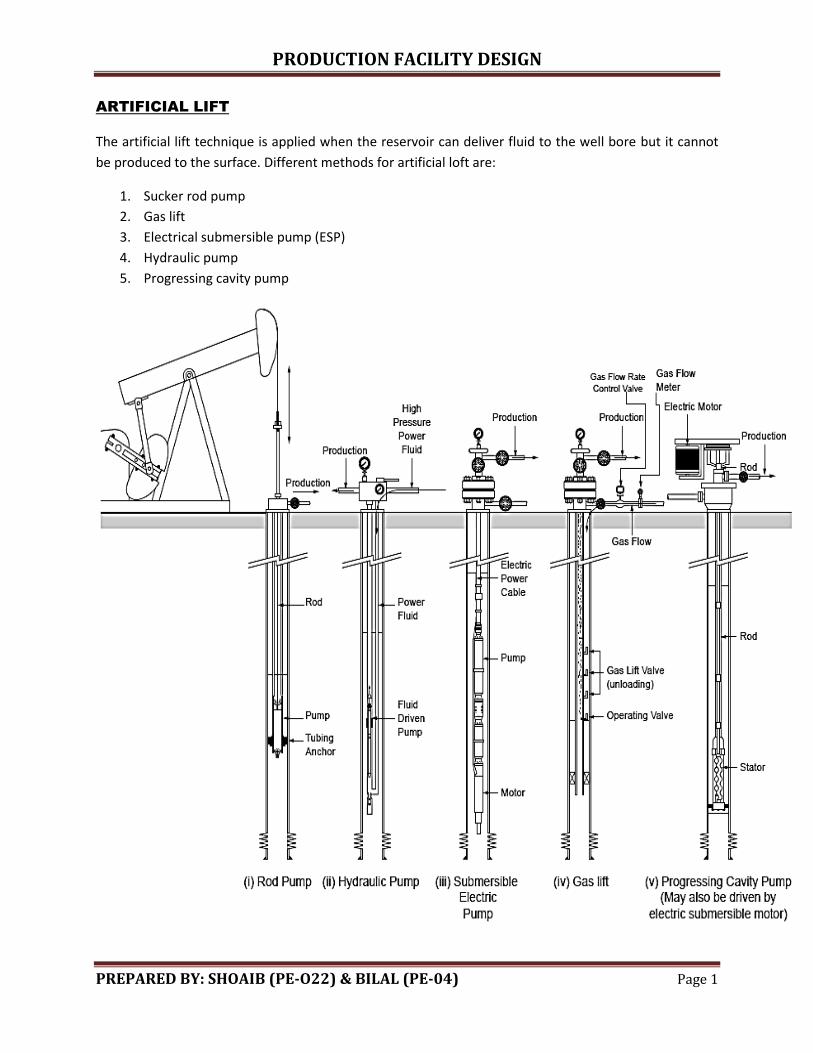
ARTIFICIAL LIFT
The artificial lift technique is applied when the reservoir can deliver fluid to the well bore but it cannot
be produced to the surface. Different methods for artificial loft are:
1. Sucker rod pump
2. Gas lift
3. Electrical submersible pump (ESP)
4. Hydraulic pump
5. Progressing cavity pump
PRODUCTION FACILITY DESIGN
PREPARED BY: SHOAIB (PE-O22) & BILAL (PE-04) Page 2
1. GAS LIFT
The gas is injected in the annulus that goes into the tubing which pushes the oil to surface and also
reduces the effective density of oil. The injected gas performs two functions:
It expands and pushes the oil to the surface
Gas reduces the effective density of oil
The gas is injected in the annulus through gas lift valves. There are two types of valves:
Unloading valves
Operating valves
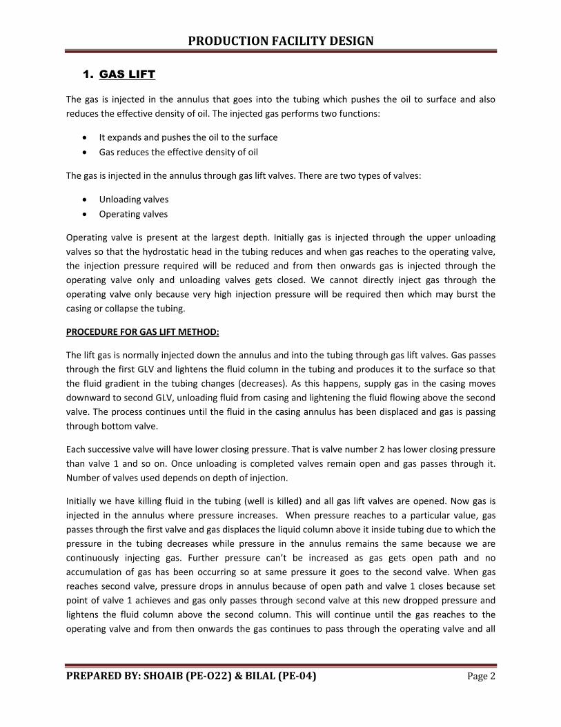
Operating valve is present at the largest depth. Initially gas is injected through the upper unloading
valves so that the hydrostatic head in the tubing reduces and when gas reaches to the operating valve,
the injection pressure required will be reduced and from then onwards gas is injected through the
operating valve only and unloading valves gets closed. We cannot directly inject gas through the
operating valve only because very high injection pressure will be required then which may burst the
casing or collapse the tubing.
PROCEDURE FOR GAS LIFT METHOD:
The lift gas is normally injected down the annulus and into the tubing through gas lift valves. Gas passes
through the first GLV and lightens the fluid column in the tubing and produces it to the surface so that
the fluid gradient in the tubing changes (decreases). As this happens, supply gas in the casing moves
downward to second GLV, unloading fluid from casing and lightening the fluid flowing above the second
valve. The process continues until the fluid in the casing annulus has been displaced and gas is passing
through bottom valve.
Each successive valve will have lower closing pressure. That is valve number 2 has lower closing pressure
than valve 1 and so on. Once unloading is completed valves remain open and gas passes through it.
Number of valves used depends on depth of injection.
Initially we have killing fluid in the tubing (well is killed) and all gas lift valves are opened. Now gas is
injected in the annulus where pressure increases. When pressure reaches to a particular value, gas
passes through the first valve and gas displaces the liquid column above it inside tubing due to which the
pressure in the tubing decreases while pressure in the annulus remains the same because we are
continuously injecting gas. Further pressure can’t be increased as gas gets open path and no
accumulation of gas has been occurring so at same pressure it goes to the second valve. When gas
reaches second valve, pressure drops in annulus because of open path and valve 1 closes because set
point of valve 1 achieves and gas only passes through second valve at this new dropped pressure and
lightens the fluid column above the second column. This will continue until the gas reaches to the
operating valve and from then onwards the gas continues to pass through the operating valve and all
PRODUCTION FACILITY DESIGN
PREPARED BY: SHOAIB (PE-O22) & BILAL (PE-04) Page 3
other valves will be closed by then. The depth at which the operating valve is installed is near the
packer.
GAS LIFT VALVES ARE OF TYPES:
Gas lift mandrels
Valves that are installed with completion assembly and completion assembly must be retrieved in order
to retrieve these valves.
Side pocket mandrel
In this case only side pocket mandrel is installed in the completion assembly and afterwards when gas
lift is needed, gas lift valves are installed in the side pocket mandrel.
Types of gas lift methods:
Continuous gas lift
Intermittent gas lift
Continuous gas lift:
In this method gas is continuously injected into the well bore which displaces the fluid and it is used
when reservoir pressure is high and reservoir continuously delivers fluid into the well bore and it is also
used when there is large availability of gas to be injected.
PRODUCTION FACILITY DESIGN
PREPARED BY: SHOAIB (PE-O22) & BILAL (PE-04) Page 4
Intermittent gas lift:
In this method, gas is injected into the well bore for some time and then gas supply is stopped for some
time. It is used when reservoir pressure is low or there is low availability of gas to be injected. When the
reservoir pressure will be low then reservoir will be delivering not much fluid into the well bore so if we
will be continuously injecting the gas then it will be useless because the injected gas will be producing
back as no fluid will be available for it to lift in the tubing.
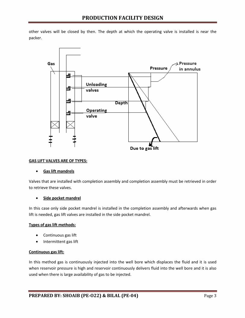
Continuous gas lift system
Gas lift system is different from other artificial lift methods as it is designed for whole field because
compressors and other facilities are installed while other methods are applied to a single well only.
Following figure shows the setup of continuous gas injection for a field.
The high pressure gas is injected through the compressor to the first manifold from where the gas is
distributed to various wells at the desired or target rates. The gas goes into the well bore, lifts the oil to
the surface and injected gas along with oil from all wells gather at the second manifold from where it
goes to the separator which separates oil and gas and the separated gas is then re-injected into the
wells after being compressed through the compressor.
PRODUCTION FACILITY DESIGN
PREPARED BY: SHOAIB (PE-O22) & BILAL (PE-04) Page 5
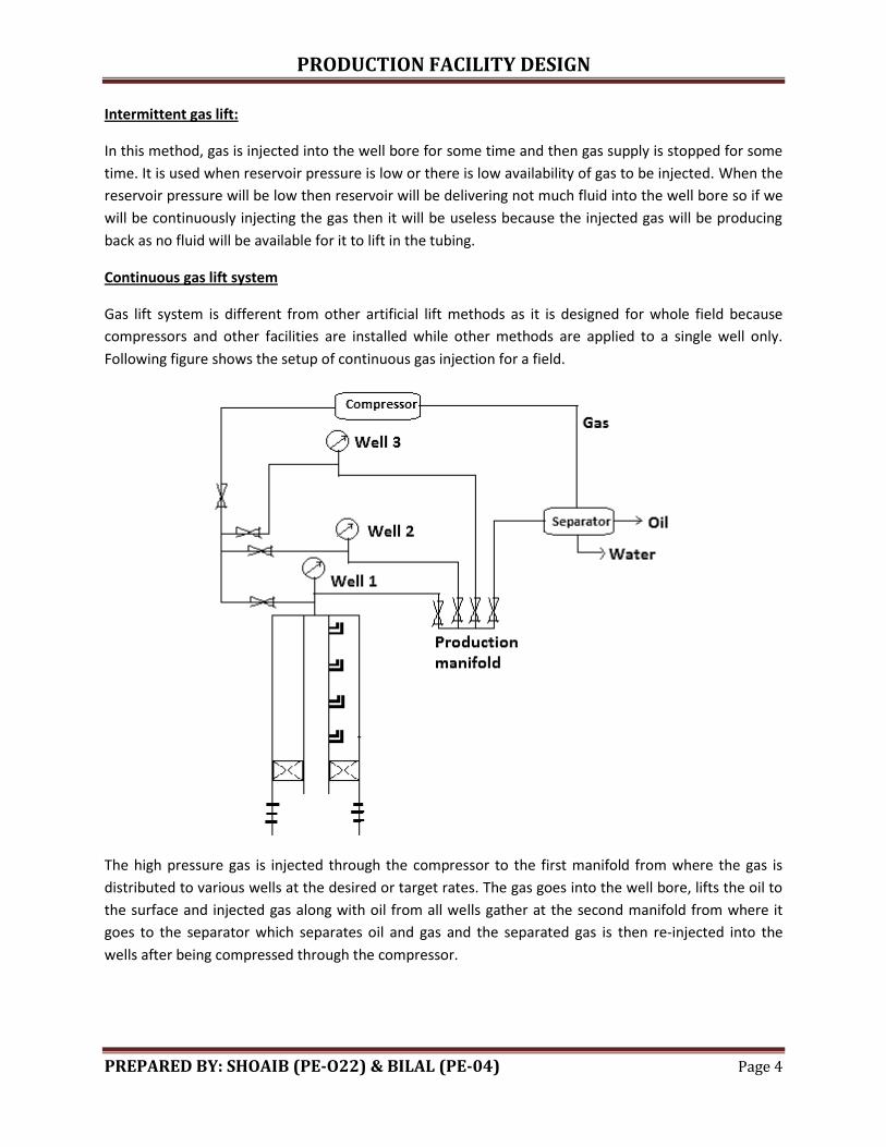
Optimum gas injection rate:
Following is the graph drawn between production rate and gas injection rate. Point ‘A’ denotes
economic optimum gas injection rate because if gas injection rate is further increased from this value
then there will be no adequate increase in the production occurs. Point ‘B’ denotes the injection rate at
which maximum liquid production occurs. The company will think that if they increase the injection rate
above the economic optimum point then whether the increased produced rate will overcome the
expenditure or not. The production rate decreases at very high gas injection rate because at very high
gas injection rate, friction losses will be dominant.
Types of gas lift valves
Unloading valves
Injection pressure operated (IPO)
Production pressure operated (PPO)
Operating valves
Orifice type
The difference between IPO and PPO is of opening and closing force. In IPO gas pressure in annulus
(injection pressure) is the driving force such that valve opens or closes due to gas pressure in the in the
annulus while in PPO, gas pressure in the tubing is the driving force such that the valve closes or opens
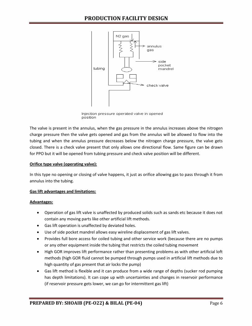
due to gas pressure in the tubing. The figure of injection pressure operated valve is shown below;
PRODUCTION FACILITY DESIGN
PREPARED BY: SHOAIB (PE-O22) & BILAL (PE-04) Page 6
The valve is present in the annulus, when the gas pressure in the annulus increases above the nitrogen
charge pressure then the valve gets opened and gas from the annulus will be allowed to flow into the
tubing and when the annulus pressure decreases below the nitrogen charge pressure, the valve gets
closed. There is a check valve present that only allows one directional flow. Same figure can be drawn
for PPO but it will be opened from tubing pressure and check valve position will be different.
Orifice type valve (operating valve):
In this type no opening or closing of valve happens, it just as orifice allowing gas to pass through it from
annulus into the tubing.
Gas lift advantages and limitations:
Advantages:
Operation of gas lift valve is unaffected by produced solids such as sands etc because it does not
contain any moving parts like other artificial lift methods.
Gas lift operation is unaffected by deviated holes.
Use of side pocket mandrel allows easy wireline displacement of gas lift valves.
Provides full bore access for coiled tubing and other service work (because there are no pumps
or any other equipment inside the tubing that restricts the coiled tubing movement
High GOR improves lift performance rather than presenting problems as with other artificial loft
methods (high GOR fluid cannot be pumped through pumps used in artificial lift methods due to
high quantity of gas present that air locks the pump)
Gas lift method is flexible and it can produce from a wide range of depths (sucker rod pumping
has depth limitations). It can cope up with uncertainties and changes in reservoir performance
(if reservoir pressure gets lower, we can go for intermittent gas lift)
PRODUCTION FACILITY DESIGN
PREPARED BY: SHOAIB (PE-O22) & BILAL (PE-04) Page 7
Tubing subsurface safety valve is available (in sucker rod pumping, due to presence of rod, we
cannot install the SSSV)
Major workover operations are infrequent when wireline servicing is possible.
Gas lift operation is independent of downhole temperature (pumps have temperature
limitations)
No electrical power is required
Multiwell production from just a single compressor
Gas lift limitations
Gas lift is inefficient in terms of energy because it lifts the oil by solution gas drive mechanism
which is the weakest drive mechanism for oil production
Gas compressors have a high capital cost. They require expensive maintenance
Annulus full of high pressure represents a safety hazard
Adequate gas supply is required throughout project life
Gas lifting of various crudes is difficult and less efficient
Wax precipitation may increase due to cooling from cold gas injection and subsequent
expansion (scales are of two types; organic and inorganic. Organic involves wax and asphaltenes
while inorganic scales include salt deposition such as NaCl, CaCO3, BaSO4, etc. Wax can be
removed by dissolving in hot oil or by scrappers, asphalts can be removed by scrappers. NaCl
and CaCO3 and can be dissolved in water and HCl respectively while BaSO4 can be removed by
scrappers only)
Hydrate blocking of surface gas injection lines can occur if gas is inadequately dried (means gas
injected must be dehydrated so hydrate may not form)
PRODUCTION FACILITY DESIGN
PREPARED BY: SHOAIB (PE-O22) & BILAL (PE-04) Page 8
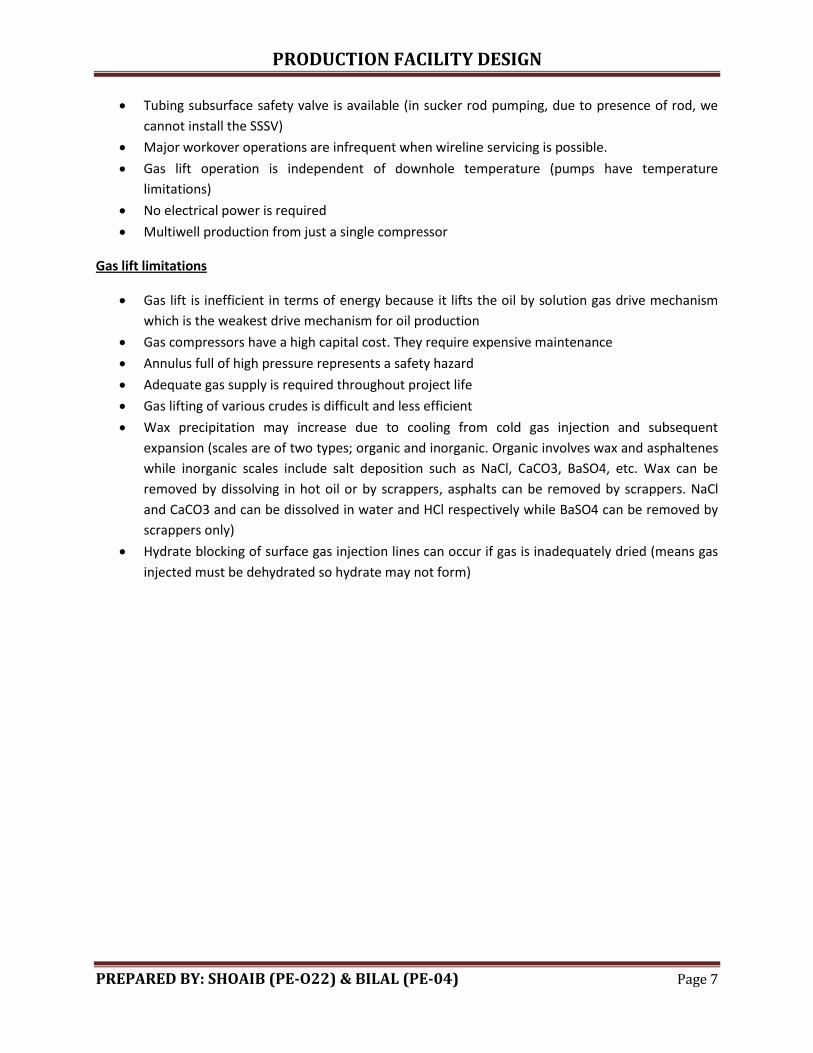
2. SUCKER ROD PUMPING
Sucker rod pumping, also called beam pumping, rod pumping was first introduced in USA. In this the oil
lifted due to mechanical energy and it is very simple and extensively used.
PRODUCTION FACILITY DESIGN
PREPARED BY: SHOAIB (PE-O22) & BILAL (PE-04) Page 9
Components of sucker rod pumping unit:
Prime mover:
It is normally an electric motor or gas combustion engine which provides required rotational power to
surface pumping unit.
V-Belt:
It provides connection between prime move and gear reducer.
Gear reducer:
It consists of two shafts:
Input shaft - It is in contact prime mover trough V-belt. It reduces fast rotation of say 600 rpm from
prime mover to as low as 20 spm. Its output shaft is connected with a crank arm.
Crank arm:
It transfers rotational motion to pitman arm and walking beam,
Pitman arm and walking beam:
They both in combination convert rotational motion into oscillatory motion.
Counter weight:
It balances all the weight applied on the other side of Sampson post so that system remains stable.
Sampson post:
It acts as a fulcrum between the counter weight (which is load) and horse head (which acts as force).
Horse head and bridle hanger:
The main purpose of horse head and bridle hanger is to ensure that the upper pull of the rod is always
vertical (no bending movement applies to stuffing box).
Polish rod and stuffing box:
They combine to make good liquid seal and force fluid to flow line.
Downhole plunger pump:
The downhole plunger pump is installed inside the tubing string. It consists of working barrel, standing
valve and travelling valve at bottom of plunger, which is connected to sucker rod.
PRODUCTION FACILITY DESIGN
PREPARED BY: SHOAIB (PE-O22) & BILAL (PE-04) Page 10
As the plunger moves downward by the sucker rod string, the travelling valve is opened, which allo the
fluid to pass through the travelling block up to the surface> During this downward motion of the
plunger, standing valve is closed so that the fluid is forced to pass through the travelling block. When the
plunger is the bottom of stroke and starts an upward movement, the travelling valve is closed and
standing valve opens. As upward movement continues, the fluid from wellbore hinders into the working
barrel through standing valve. The fluid continues to fill the volume above the standing valve until the
plunger reaches the top of its stroke.
TYPES OF SURFACE PUMPING UNIT:
There are three types of surface pumping unit:
Conventional unit
Lufkin Mark-II unit
Air-balanced unit
In Lufkin Mark-II unit and air balanced unit, the pitman arm and horse head are at the same side of
walking beam while on conventional unit they are on the opposite sides. In air balanced unit instead of
using counter physical weight, air cylinders are used to balance the torque.
The API standard used to describe specifications of sucker rod pumping unit is:
C-230D-200-74
The first letter describes the type of surface pumping unit, here ‘C’ denotes the conventional
pumping unit. ‘A’ for air balanced and ‘M’ for mark-II unit.
230 indicates peak torque rating with unit thousand inch-lb.
‘D’ indicates the type of gear reducer (double reduction gear)
200 indicates polish rod load capacity in thousands of lbs.
74 indicates stroke length in inches
Subsurface pumping unit types:
Tubing pump
Rod pump
Tubing pump:
The working barrel with standing valve is made up (attached) to the bottom of production tubing and
run into the valve in the tubing. Plunger with travelling valve is run into the tubing with sucker rod
(barrel is part of tubing; plunger and valve are part of sucker rod).
Rod pump:
A rod pump (both working barrel and plunger)is run into the well on the sucker rod, and is seated on
wedge type seat that is fixed to the bottom joint of tubing.
PRODUCTION FACILITY DESIGN
PREPARED BY: SHOAIB (PE-O22) & BILAL (PE-04) Page 11
Advantages of sucker rod pumping unit:
Very simple mechanism
Unit can be transferred from one well to another
Very high efficiency
Pumping wells of even very low pressure
High temperature and high viscous oil pumping
Can be used in case of multiple completion (one horse head will driving two sucker rods)
Gas lift is used when we have large number of wells on large field but this method can be used
for small number of wells.
Disadvantages:
Large size (cannot be used in offshore)
Do not prefer in deep wells (limited load capacity of rod)
In case of large sand production, downhole pump will be damaged
It cannot be used in wells where large volumes of gas produced because presence of gas lessens
the efficiency of pump due to air locking.
In deviated wells, centralizers are used (does not prefer, very complex)
Large friction produced, very large lubrication is required
The liquid column in the tubing and tubing casing annulus should be above the bottom valve at
all times otherwise air will be sucked and efficiency will be less so ecometer is run that tells us
about the liquid level (sound waves sent and travel time is calculated)
SUCKER ROD NUMERICALS
Pump rate calculation
(
)
Where;
(
)
Q1. Calculate the pump rate in bbls/day of sucker rod pump such that area of working barrel is 50in2.
Stroke length is 60in and the maximum speed of pump is 24strokes/minute. Efficiency of pump is 80%.
PRODUCTION FACILITY DESIGN
PREPARED BY: SHOAIB (PE-O22) & BILAL (PE-04) Page 12
( )
Q2. An E&P Company found that efficiency of sucker rod decreases with time. They want to calculate
efficiency of sucker rod after 1 year of production, when its initial efficiency is 90%. Now the sucker
rod has surface stroke length of 64 inches, rod stretch is around 20 inches due to load, plunger over
travel value is 10 inches and plunger length is 5 inches. Area of working barrel is 40 in2. Maximum
pump speed is 20strokes/min and pump rate is 4055bbls/day.
Q3. Calculate the volume of oil lifted by sucker rod in barrels per stroke, when area of working barrel
is 300cm2. Downhole plunger pump is located at 6000ft depth through a sucker rod having an area of
0.815in2. The length of crank arm and pitman arm are 10 in and 15 in respectively (neglect rod stretch
and over travel effect)?
Note: One complete rotation of crankshaft covers stroke length (upward and downward)
( )
PRODUCTION FACILITY DESIGN
PREPARED BY: SHOAIB (PE-O22) & BILAL (PE-04) Page 13
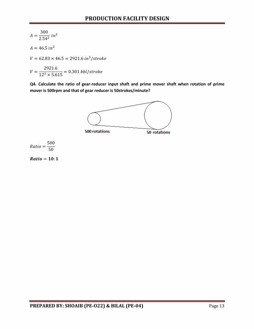
Q4. Calculate the ratio of gear-reducer input shaft and prime mover shaft when rotation of prime
mover is 500rpm and that of gear reducer is 50strokes/minute?
PRODUCTION FACILITY DESIGN
PREPARED BY: SHOAIB (PE-O22) & BILAL (PE-04) Page 14
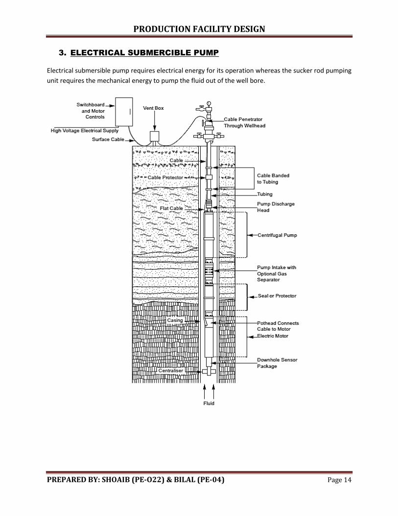
3. ELECTRICAL SUBMERCIBLE PUMP
Electrical submersible pump requires electrical energy for its operation whereas the sucker rod pumping
unit requires the mechanical energy to pump the fluid out of the well bore.
PRODUCTION FACILITY DESIGN
PREPARED BY: SHOAIB (PE-O22) & BILAL (PE-04) Page 15
Mechanism:
The overall ESP system operates like any electrical pump commonly used. In ESP, electrical energy is
transported to the downhole electric motors by the electric cables. These cables are run on the side of
the tubing and also attached to it. These provide electrical energy to run downhole electric motors. The
electric motor drives the pump and the pump imparts energy to the fluid in the form of hydraulic power
which lifts the fluid to the surface,
Components:
Vent box:
Vent box separates the surface cable from the downhole cable. This ensures that any gas which travels
up the downhole cable does not reach the electric switch gear.
PRODUCTION FACILITY DESIGN
PREPARED BY: SHOAIB (PE-O22) & BILAL (PE-04) Page 16
Cable protector:
They provide additional protection to cable and are installed at critical points.
Port head:
The cable enters the electric motor housing at the port head. The cable contains two wires; one carries
current to the downhole while the other sends signal to the surface of various types.
Seal or Protector:
It connects the central drive shaft of the electric motor to the pump. Additionally, it provides:
o Isolation between the lubrication motor oil and well fluids
o Equalize inter motor pressure with well annulus pressure
o Absorb any thrust generated by the pump
Downhole sensors:
It is used to measure:
o Pump suction and discharge pressure and temperature
o Electric motor temperature
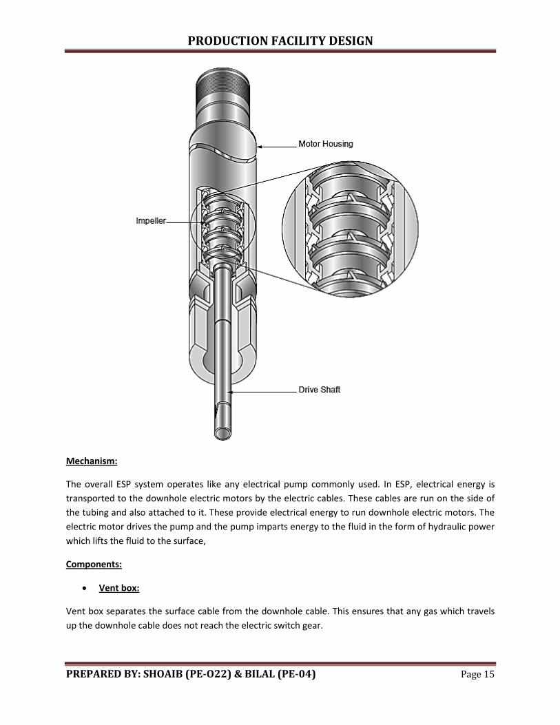
Pump:
The pump consists of rotating centrifugal impellers running on a central drive shaft inside the stack of
stationary diffuser. Rotation of impeller accelerates the liquid to the pump which is then discharged into
the diffuser where its kinetic energy is transferred into the potential energy that is pressure is increased.
Pressure is increased in proportion to the number of stages. The pump capacity that is the volume being
pumped increases as the diameter of the impeller increases.
Gas separator:
It is the rotary gas separator that separates the lower density gaseous phase from the density of the
liquid phase.
Check valve:
Check valve is installed in the tubing and ensure only one directional flow to the tubing.
Advantages:
Pump very high volume of oil (60000 bbl)
Very suitable for offshore well as it has very small surface size equipment
In deviated wells, it can be used with centralizers
Easy to install and operate
Can be used in deep wells
PRODUCTION FACILITY DESIGN
PREPARED BY: SHOAIB (PE-O22) & BILAL (PE-04) Page 17
Better efficiency as compared to sucker rod pumping unit
In high water cut wells, we can use it
Disadvantages:
Expensive than sucker rod
High voltage required
In high GOR wells, it cannot be used
If well is producing sand, then it cannot be used
It cannot be used in high temperature sensitive wells (pump is used well above the perforation)
Cannot pump very high viscous fluid
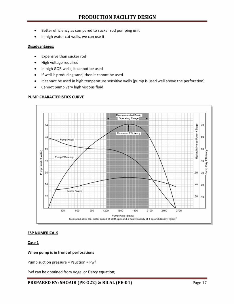
PUMP CHARACTERISTICS CURVE
ESP NUMERICALS
Case 1
When pump is in front of perforations
Pump suction pressure = Psuction = Pwf
Pwf can be obtained from Vogel or Darcy equation;
PRODUCTION FACILITY DESIGN
PREPARED BY: SHOAIB (PE-O22) & BILAL (PE-04) Page 18
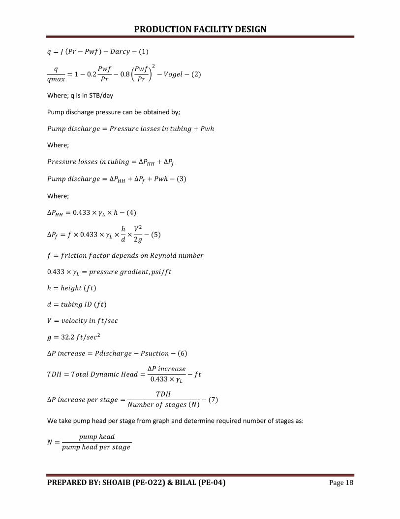
( ) ( )
(
)
( )
Where; q is in STB/day
Pump discharge pressure can be obtained by;
Where;
( )
Where;
( )
( )
( )
( )
( )
( ) ( )
We take pump head per stage from graph and determine required number of stages as:
PRODUCTION FACILITY DESIGN
PREPARED BY: SHOAIB (PE-O22) & BILAL (PE-04) Page 19
In graph, we are given pump head in terms of height rather than pressure so that it can be used for any
fluid case.
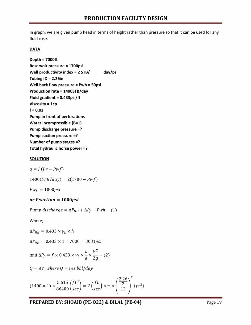
DATA
Depth = 7000ft
Reservoir pressure = 1700psi
Well productivity index = 2 STB/ day/psi
Tubing ID = 2.26in
Well back flow pressure = Pwh = 50psi
Production rate = 1400STB/day
Fluid gradient = 0.433psi/ft
Viscosity = 1cp
f = 0.03
Pump in front of perforations
Water incompressible (B=1)
Pump discharge pressure =?
Pump suction pressure =?
Number of pump stages =?
Total hydraulic horse power =?
SOLUTION
( )
( ) ( )
( )
Where;
( )
( )
(
) (
) (
)
( )
PRODUCTION FACILITY DESIGN
PREPARED BY: SHOAIB (PE-O22) & BILAL (PE-04) Page 20
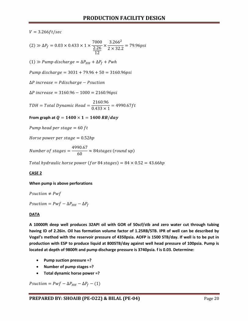
( )
( )
From graph at
( )
( )
CASE 2
When pump is above perforations
DATA
A 10000ft deep well produces 32API oil with GOR of 50scf/stb and zero water cut through tubing
having ID of 2.26in. Oil has formation volume factor of 1.25RB/STB. IPR of well can be described by
Vogel’s method with the reservoir pressure of 4350psia. AOFP is 1500 STB/day. If well is to be put in
production with ESP to produce liquid at 800STB/day against well head pressure of 100psia. Pump is
located at depth of 9800ft and pump discharge pressure is 3740psia. f is 0.03. Determine:
Pump suction pressure =?
Number of pump stages =?
Total dynamic horse power =?
( )
PRODUCTION FACILITY DESIGN
PREPARED BY: SHOAIB (PE-O22) & BILAL (PE-04) Page 21
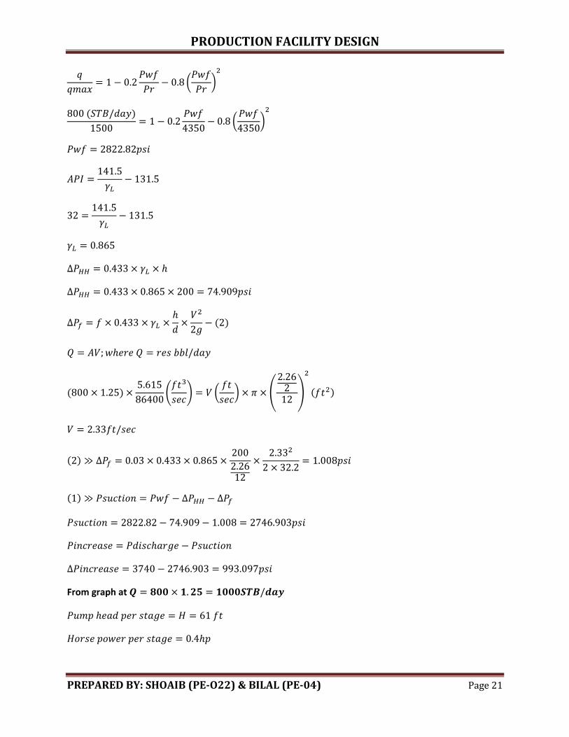
(
)
( )
(
)
( )
( )
(
) (
) (
)
( )
( )
( )
From graph at
PRODUCTION FACILITY DESIGN
PREPARED BY: SHOAIB (PE-O22) & BILAL (PE-04) Page 22
( )
( )
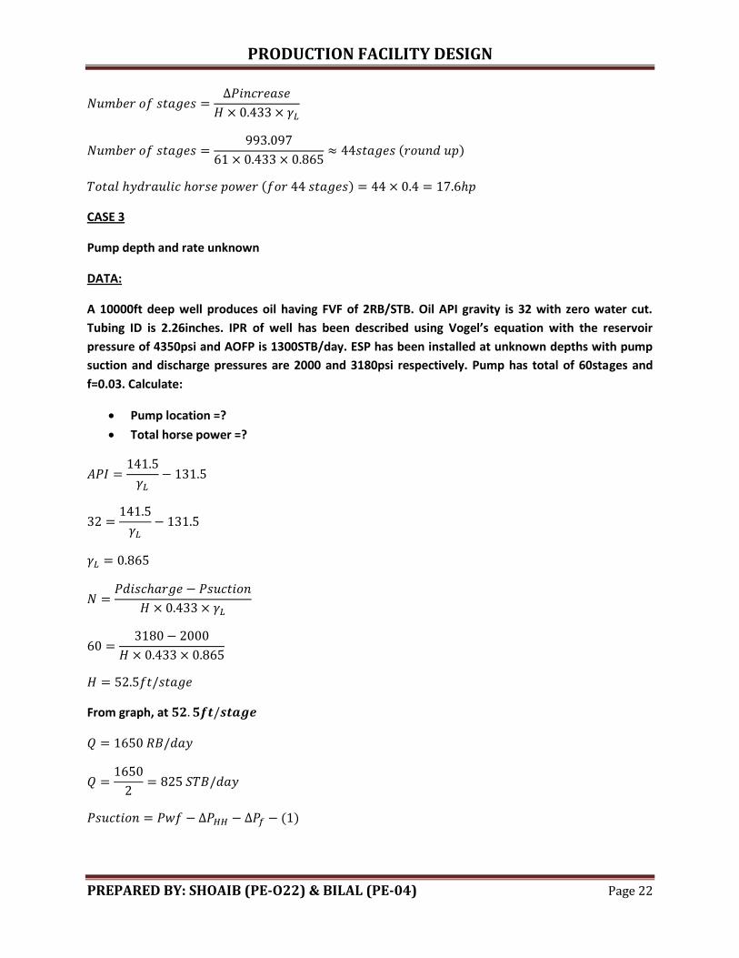
CASE 3
Pump depth and rate unknown
DATA:
A 10000ft deep well produces oil having FVF of 2RB/STB. Oil API gravity is 32 with zero water cut.
Tubing ID is 2.26inches. IPR of well has been described using Vogel’s equation with the reservoir
pressure of 4350psi and AOFP is 1300STB/day. ESP has been installed at unknown depths with pump
suction and discharge pressures are 2000 and 3180psi respectively. Pump has total of 60stages and
f=0.03. Calculate:
Pump location =?
Total horse power =?
From graph, at
( )
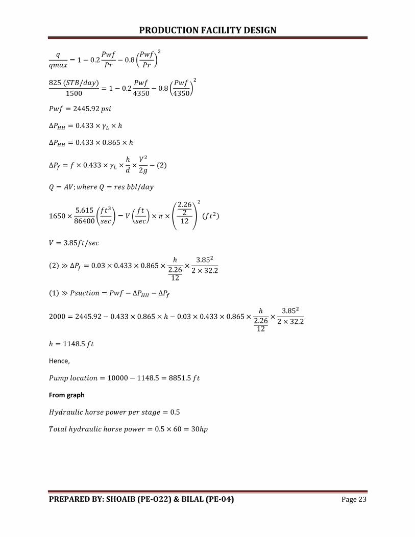
PRODUCTION FACILITY DESIGN
PREPARED BY: SHOAIB (PE-O22) & BILAL (PE-04) Page 23
(
)
( )
(
)
( )
(
) (
) (
)
( )
( )
( )
Hence,
From graph
PRODUCTION FACILITY DESIGN
PREPARED BY: SHOAIB (PE-O22) & BILAL (PE-04) Page 24
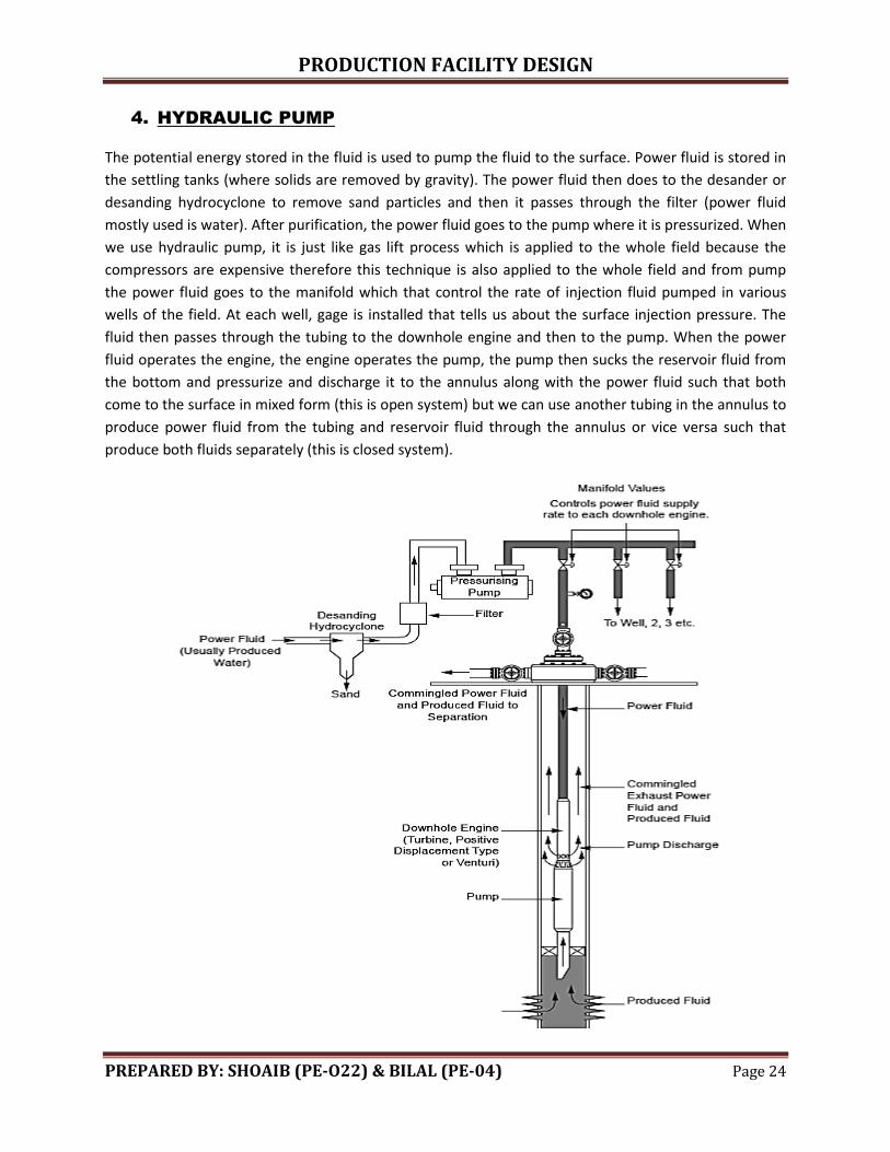
4. HYDRAULIC PUMP
The potential energy stored in the fluid is used to pump the fluid to the surface. Power fluid is stored in
the settling tanks (where solids are removed by gravity). The power fluid then does to the desander or
desanding hydrocyclone to remove sand particles and then it passes through the filter (power fluid
mostly used is water). After purification, the power fluid goes to the pump where it is pressurized. When
we use hydraulic pump, it is just like gas lift process which is applied to the whole field because the
compressors are expensive therefore this technique is also applied to the whole field and from pump
the power fluid goes to the manifold which that control the rate of injection fluid pumped in various
wells of the field. At each well, gage is installed that tells us about the surface injection pressure. The
fluid then passes through the tubing to the downhole engine and then to the pump. When the power
fluid operates the engine, the engine operates the pump, the pump then sucks the reservoir fluid from
the bottom and pressurize and discharge it to the annulus along with the power fluid such that both
come to the surface in mixed form (this is open system) but we can use another tubing in the annulus to
produce power fluid from the tubing and reservoir fluid through the annulus or vice versa such that
produce both fluids separately (this is closed system).
PRODUCTION FACILITY DESIGN
PREPARED BY: SHOAIB (PE-O22) & BILAL (PE-04) Page 25
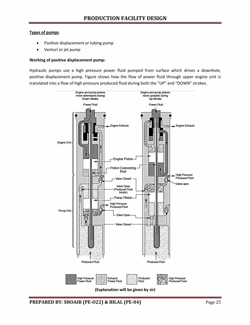
Types of pumps
Positive displacement or tubing pump
Venturi or jet pump
Working of positive displacement pump:
Hydraulic pumps use a high pressure power fluid pumped from surface which drives a downhole,
positive displacement pump. Figure shows how the flow of power fluid through upper engine unit is
translated into a flow of high pressure produced fluid during both the “UP” and “DOWN” strokes.
(Explanation will be given by sir)
PRODUCTION FACILITY DESIGN
PREPARED BY: SHOAIB (PE-O22) & BILAL (PE-04) Page 26
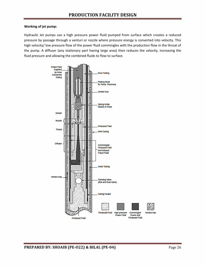
Working of jet pump:
Hydraulic Jet pumps use a high pressure power fluid pumped from surface which creates a reduced
pressure by passage through a venturi or nozzle where pressure energy is converted into velocity. This
high velocity/ low pressure flow of the power fluid commingles with the production flow in the throat of
the pump. A diffuser (any stationary part having large area) then reduces the velocity, increasing the
fluid pressure and allowing the combined fluids to flow to surface.
PRODUCTION FACILITY DESIGN
PREPARED BY: SHOAIB (PE-O22) & BILAL (PE-04) Page 27
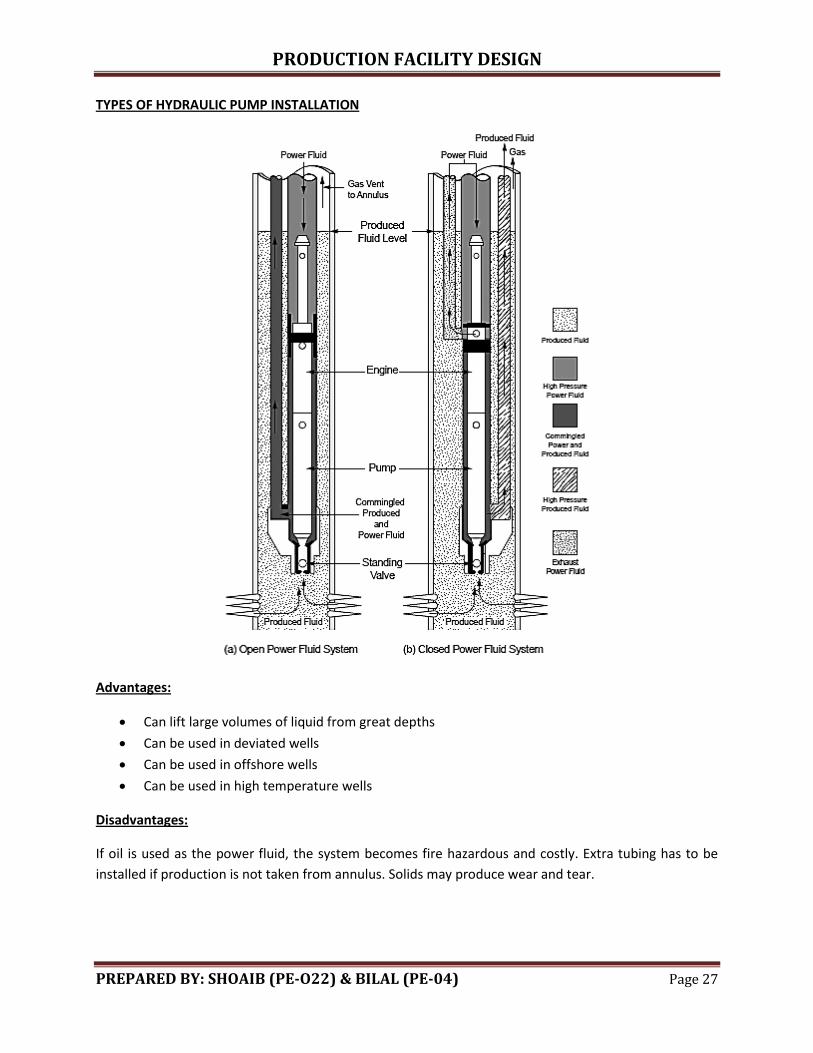
TYPES OF HYDRAULIC PUMP INSTALLATION
Advantages:
Can lift large volumes of liquid from great depths
Can be used in deviated wells
Can be used in offshore wells
Can be used in high temperature wells
Disadvantages:
If oil is used as the power fluid, the system becomes fire hazardous and costly. Extra tubing has to be
installed if production is not taken from annulus. Solids may produce wear and tear.
PRODUCTION FACILITY DESIGN
PREPARED BY: SHOAIB (PE-O22) & BILAL (PE-04) Page 28
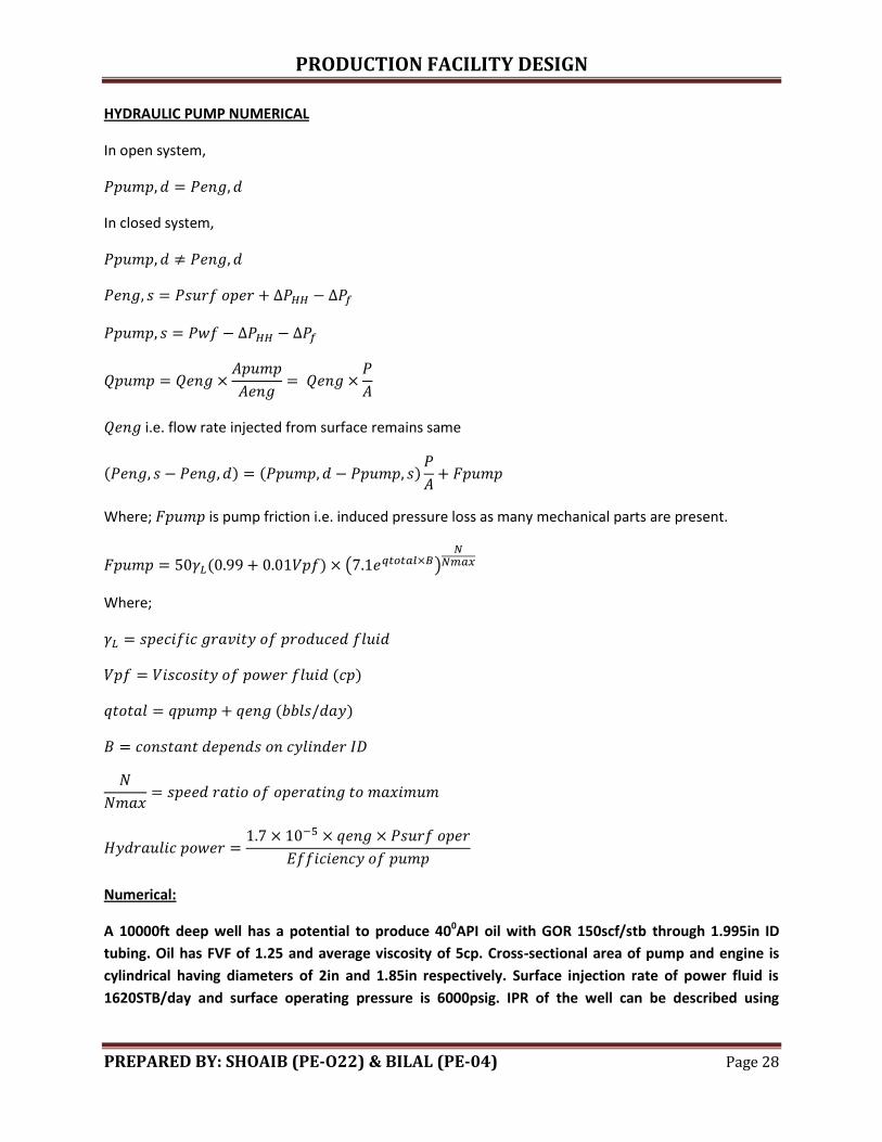
HYDRAULIC PUMP NUMERICAL
In open system,
In closed system,
i.e. flow rate injected from surface remains same
( ) ( )
Where; is pump friction i.e. induced pressure loss as many mechanical parts are present.
( ) ( )
Where;
( )
( )
Numerical:
A 10000ft deep well has a potential to produce 400API oil with GOR 150scf/stb through 1.995in ID
tubing. Oil has FVF of 1.25 and average viscosity of 5cp. Cross-sectional area of pump and engine is
cylindrical having diameters of 2in and 1.85in respectively. Surface injection rate of power fluid is
1620STB/day and surface operating pressure is 6000psig. IPR of the well can be described using
PRODUCTION FACILITY DESIGN
PREPARED BY: SHOAIB (PE-O22) & BILAL (PE-04) Page 29
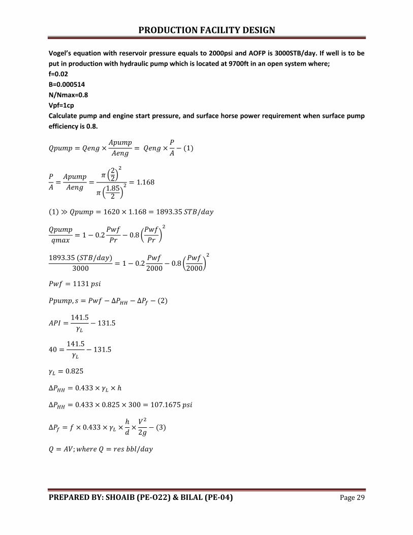
Vogel’s equation with reservoir pressure equals to 2000psi and AOFP is 3000STB/day. If well is to be
put in production with hydraulic pump which is located at 9700ft in an open system where;
f=0.02
B=0.000514
N/Nmax=0.8
Vpf=1cp
Calculate pump and engine start pressure, and surface horse power requirement when surface pump
efficiency is 0.8.
( )
( )
( )
( )
(
)
( )
(
)
( )
( )
PRODUCTION FACILITY DESIGN
PREPARED BY: SHOAIB (PE-O22) & BILAL (PE-04) Page 30
( )
(
) (
) (
)
( )
( )
( )
( )
( )
( )
(
) (
) (
)
( )
( )
( )
( )
( ) ( )
( ) ( )
( ) ( )
( )
In open system,
PRODUCTION FACILITY DESIGN
PREPARED BY: SHOAIB (PE-O22) & BILAL (PE-04) Page 31
( ) ( ) ( )
( ) ( )( )
PRODUCTION FACILITY DESIGN
PREPARED BY: SHOAIB (PE-O22) & BILAL (PE-04) Page 32
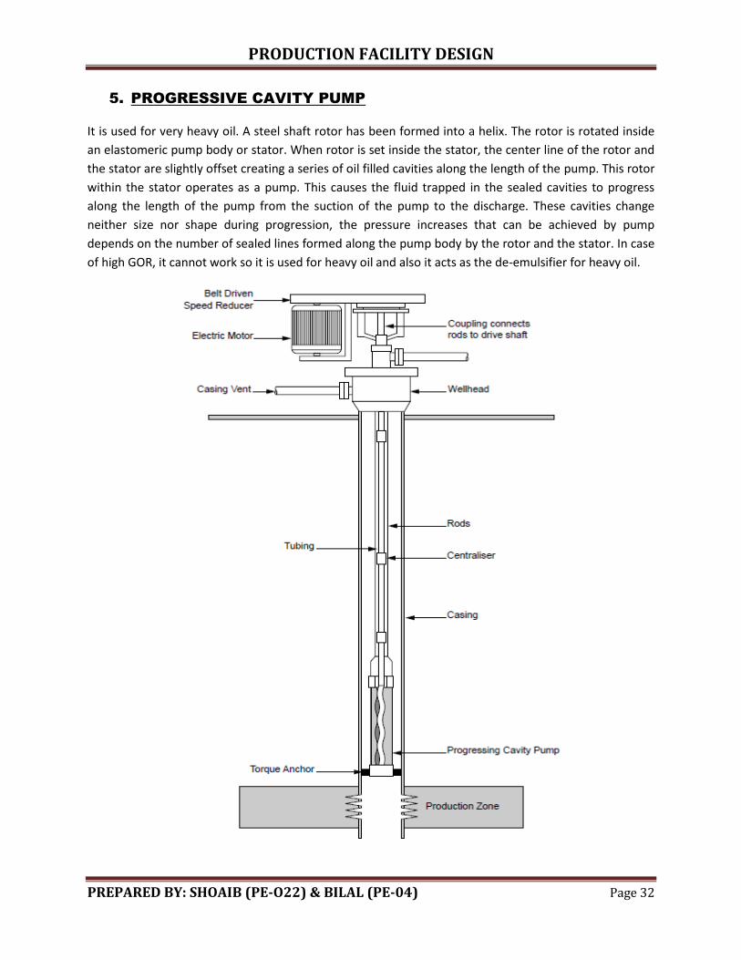
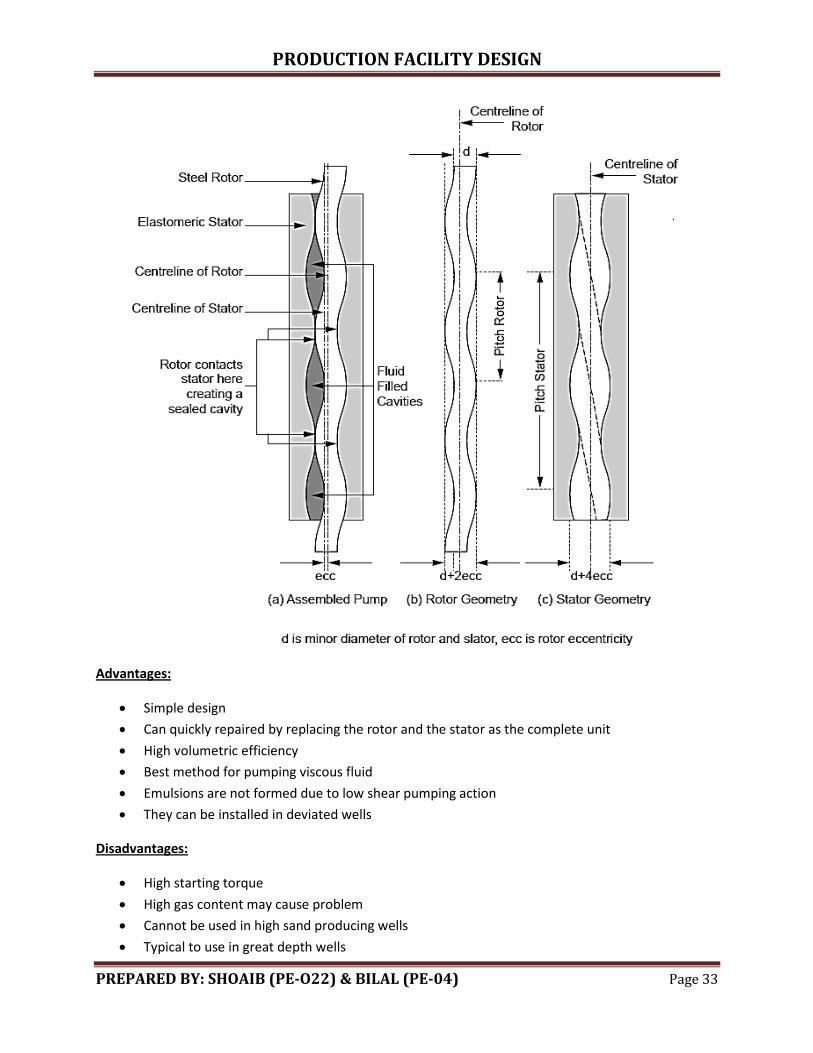
5. PROGRESSIVE CAVITY PUMP
It is used for very heavy oil. A steel shaft rotor has been formed into a helix. The rotor is rotated inside
an elastomeric pump body or stator. When rotor is set inside the stator, the center line of the rotor and
the stator are slightly offset creating a series of oil filled cavities along the length of the pump. This rotor
within the stator operates as a pump. This causes the fluid trapped in the sealed cavities to progress
along the length of the pump from the suction of the pump to the discharge. These cavities change
neither size nor shape during progression, the pressure increases that can be achieved by pump
depends on the number of sealed lines formed along the pump body by the rotor and the stator. In case
of high GOR, it cannot work so it is used for heavy oil and also it acts as the de-emulsifier for heavy oil.
PRODUCTION FACILITY DESIGN
PREPARED BY: SHOAIB (PE-O22) & BILAL (PE-04) Page 33
Advantages:
Simple design
Can quickly repaired by replacing the rotor and the stator as the complete unit
High volumetric efficiency
Best method for pumping viscous fluid
Emulsions are not formed due to low shear pumping action
They can be installed in deviated wells
Disadvantages:
High starting torque
High gas content may cause problem
Cannot be used in high sand producing wells
Typical to use in great depth wells
PRODUCTION FACILITY DESIGN
PREPARED BY: SHOAIB (PE-O22) & BILAL (PE-04) Page 34
ARTIFICIAL LIFT SELECTION CONSIDERATION/ CRITERIA
1. Well and reservoir characterization
2. Field or well location
3. Operational problems
4. Economics
Well and reservoir characterization
Size of production casing
Tubing maximum size
Gross production rate (Plateau rate)
Depth of well
Deviation
Nature of producing fluid (GOR, water cut, sand contents with fluid, composition)
PI Index (well inflow)- if J is less then we will not go for artificial because it will not be
economical
Field or well location
Onshore/ offshore (in offshore, we need to consider platform size and weight it can bear. We
never use sucker rod in offshore and usually ESP is used)
Climate
Distance from well head to production facility (if distance is large then gas lift will not be used as
pressure losses will be high from compressor discharge to well head. We use ESP as single wire
is required in ESP)
Energy requirement of pump (availability/losses/efficiency of gas engine/diesel
engine/generator)
Operational problems
In this, we consider factors which may occur in future
Excess sand or gas coning/production
Bottom hole temperature abnormality
Corrosive environment
Economics
Capital investment (CAPEX)
Operational cost (OPEX)- it is rate dependent
Maintenance cost (for e.g., we need to remove tubing in ESP for maintenance so its cost is large
and it is considered separately from operational cost)
Number of wells in field (compressors are installed when many wells are present in case of gas
lift)