Embed Size (px)
Citation preview

Starter Panels
Catalog 2011/2012
Control panelsand protectionfor motor pumpsand motors
Production and control of energy

MANIERO ELETTRONICA:a full range of standard panels ...
...and special bespoke panels tocustomer specifications.
SistemiAntiallagamento
Catalogo 2010/2011
Catalogo 2011
Quadri elettrici Quadri di comandoe protezioneper elettropompee motori
PRODUZIONE E CONTROLLO DELL’ENERGIA
Quadri elettriciper piscine
Control panelsfor swimming pools
Coffrets électriquespour piscines
Catalogo
PRODUZIONE E CONTROLLO DELL’ENERGIA
Quadri persistemi a
pressionecostante
PRODUZIONE E CONTROLLO DELL’ENERGIA
Quadri elettriciFOX

INDEX Starter panelsControl panelsand protection
for motor pumpsand motors
SUMMARY OF CHARACTERISTICS
OF ELECTRICAL PANELS 2-3
SECTION 1 - MOTOR PROTECTION
PM10/...kW-C-T-IL-2 7
PM10/...kW-C-T-IC 8
PT10/...A-T 9
SECTION 2 - ELECTRONIC CONTROL PANELS
SMART PANELS
SMART 15-17
PANELS 1 PUMP
QMD10/...kW-T 18
QMD10/...kW-C-T 19
QA/50B 20
QA/60C 21
PANELS 2 PUMPS
QMD20/...kW-T-SI-2 22
QTD20/...kW-T-SI 23
CONTROL SYSTEMS FOR EXPANSION VESSELS
CVE 24
SECTION 3 - ELECTROMECHANICAL PANELS
PANELS 1 PUMP
QMDE10/...A-T 26-27
QMDE10/...A-T-AR 28-29
QTDE10/...A-T 30-31
QTDE10/...A-T-AR 32-33
QTSE10/...A-T 34-35
QTSE10/...A-T-AR 36-37
QTRE10/...A-T 38-39
QTSS10/...A-T 40-41
QTIF10 42
Greenhouses control panels 43
PANELS 2 PUMPS
QMDE20/...A-T 44-45
QMDE20/...A-T-AR 46-47
QTDE20/...A-T 48-49
QTDE20/...A-T-AR 50-51
QTSE20/...A-T 52-53
QTSE20/...A-T-AR 54-55
PANELS 3 PUMPS
QTDE30/...A-T 56-57
QTDE30/...A-T-AR 58-59
QTSE30/...A-T 60-61
QTSE30/...A-T-AR 62-63
SECTION 4 - FIRE FIGHTING PANELS EN 12845
QTDAS10/...kW-A-2 65
QTDA10/...kW-F-3 66
QTSA10/...kW-F-3 67
QMA 68
SECTION 5 - PANELS FOR CONSTANT PRESSURE SYSTEMS
QTIP series 69-73
QPC series 74-90
SECTION 6 - CONTROL PANELS FOR TANKS
Control panels for tanks (brochure) 92
SECTION 7 - ADDITIONAL EQUIPMENT
Accessories for alarm systems 94-95
TLC units, temperature controllers, ultrasonic
level transmitters 96-97
Phase control with alarm 98
Electronic timers 99
Exchangers and electronic modules 100-101
Additional equipment and level controls 102
Heat exchangers for motor pumps 103
Level control probes 104
Float switches 105
Anemometer and rain sensor 106
SECTION 8 - ACCESSORIES FOR PANELS
Timer and counter 108-109
Accessories 110-112
CAT PANELS 2011
691www.manieroelettronica.it

SUMMARY OF CHARACTERISTICSELECTRICAL PANELS
TYPE
PROTEC-TIONSMOTOR
ELECTRONIC CONTROL PANELS
ELECTR
No. PUMPS 1 1 2 1
POWER 230V 400V 230V 400V 230V 400V 230V 400V
START [1] D D D D D S-T R SS IF
FUSE [2] • • • • • • • • • • • • •
AP
PL
ICA
TIO
NS
EMPTYING • • • • • • • • • • •
FILLING • • • • • • • • •
PRESSURIZATION • • • • • • • • •
FU
NC
TIO
NS
Motherboardready (SMP) • •
Alarm output • • • •Sensor input
Motor thermal • • •
Over and under voltage protection
Control dry running
Integrated heat exchanger • •
Graphic display •
Model
PM
10/.
..KW
PT1
0/...
A-T
QA
/50B
QA
/60C
QM
D20
/...K
W-T
-SI-
2
QTD
20/.
..KW
-T-S
I-2
QM
DE
10/.
..A-T
QM
DE
10/.
..A-T
-AR
QTD
E10
/...A
-T
QTD
E10
/...A
-T-A
R
QTS
E10
/...A
-T
QTS
E10
/...A
-T-A
R
QTR
E10
/...A
-T
QTS
S10/
...A
-T
QTI
F10/
...A
-A
Page 7.8 9 20 21 22 23 26.27 28.29 30.31 32.33 34.35 36.37 38.39 40.41 42
(1) D = Direct, ST = Star Delta, R = Reactance, SS = Soft-Start, IF = Frequency Inverters.
(2) If the fuse is present, each motor is provided with its own protection with fuses.
www.manieroelettronica.it2
Reference to 400V according to
IEC60947-4-1
I - ref [A] 0.2 0.3 0.44 0.6 0.85 1.1 1.5 1.9 2.7 3.6 4.9 6.5 8.5 11.5
P - ref[kW] 0.06 0.09 0.12 0.18 0.25 0.37 0.55 0.75 1.1 1.5 2.2 3 4 5.5
[Hp] 0.08 0.12 0.16 0.24 0.34 0.5 0.75 1 1.5 2 3 4 5.5 7.5

3www.manieroelettronica.it
OMECHANICAL PANELS
2 3
230V 400V 400V
D D S-T D S-T
• • • • • • • • • •
• • • • • • • • • •
• • • • •
• • • • •
• • • • •
• • • • •
• • • • •
SM
AR
T
QT
IP
QP
C
CV
E
GR
EE
NH
OU
SE P
AN
ELS
QM
DE
20/.
..A-T
QM
DE
20/.
..A-T
-AR
QTD
E20
/...A
-T
QTD
E20
/...A
-T-A
R
QTS
E20
/...A
-T
QTS
E20
/...A
-T-A
R
QTD
E30
/...A
-T
QTD
E30
/...A
-T-A
R
QTS
E30
/...A
-T
QTS
E30
/...A
-T-A
R
44.45 46.47 48.49 50.51 52.53 54.55 56.57 58.59 60.61 62.63 15÷17 69÷73 74÷90 24 43
15.5 22 29 35 41 55 66 80 97 132 160 195 230 280 350 430 540 610 690 850
7.5 11 15 18.5 22 30 37 45 55 75 90 110 132 160 200 250 315 355 400 500
10 15 20 25 30 40 50 60 75 100 120 150 180 220 270 335 420 475 535 670

www.manieroelettronica.it4
PANELS FOR CONSTRUCTION SITES
PANELS FOR TANKS
START WITH SOFT-START / 6 PUMPS 30kW
PANELS FOR LIFTING STATIONS
REACTOR START / 1 200kW PUMP
NON-STANDARD PANELSManiero can produce on request control panels for many areas related to the handling of water: our flexibility always allows us to create unique items built according to current regulations. We use normally PLC, sensors of any type, we manufacture ATEX panels, panels for tanks, distribution control panels, etc..

www.manieroelettronica.it 5
FIRST RAIN PANELS
ATEX CONTROL PANELS
START WITH AUTOTRANSFORMER / 3 PUMPS 90kW
PANELS FOR LIFTING STATIONS
FOR SEWAGE TREATMENT PLANT

www.manieroelettronica.it6
MOTORPROTECTIONS
"...our horizonis the goal
of our customers..."

NOTES:
in general the power value is indicative, in order to choose the model correctly make sure that motor ampere absorption is included in the motor thermal protection value.
--- For other versions, please consult our technical/sales service. --- MANIERO ELETTRONICA reserves the right to modify products without prior notice.
GENERAL CHARACTERISTICS:
- Power supply 230V ~ 50/60Hz ± 10%;- Thermal protection externally resettable;- Run capacitor- Illuminated switch- Casing made of thermoplastic material;- Output with cable gland;- Protection degree IP 55;
P
B
A
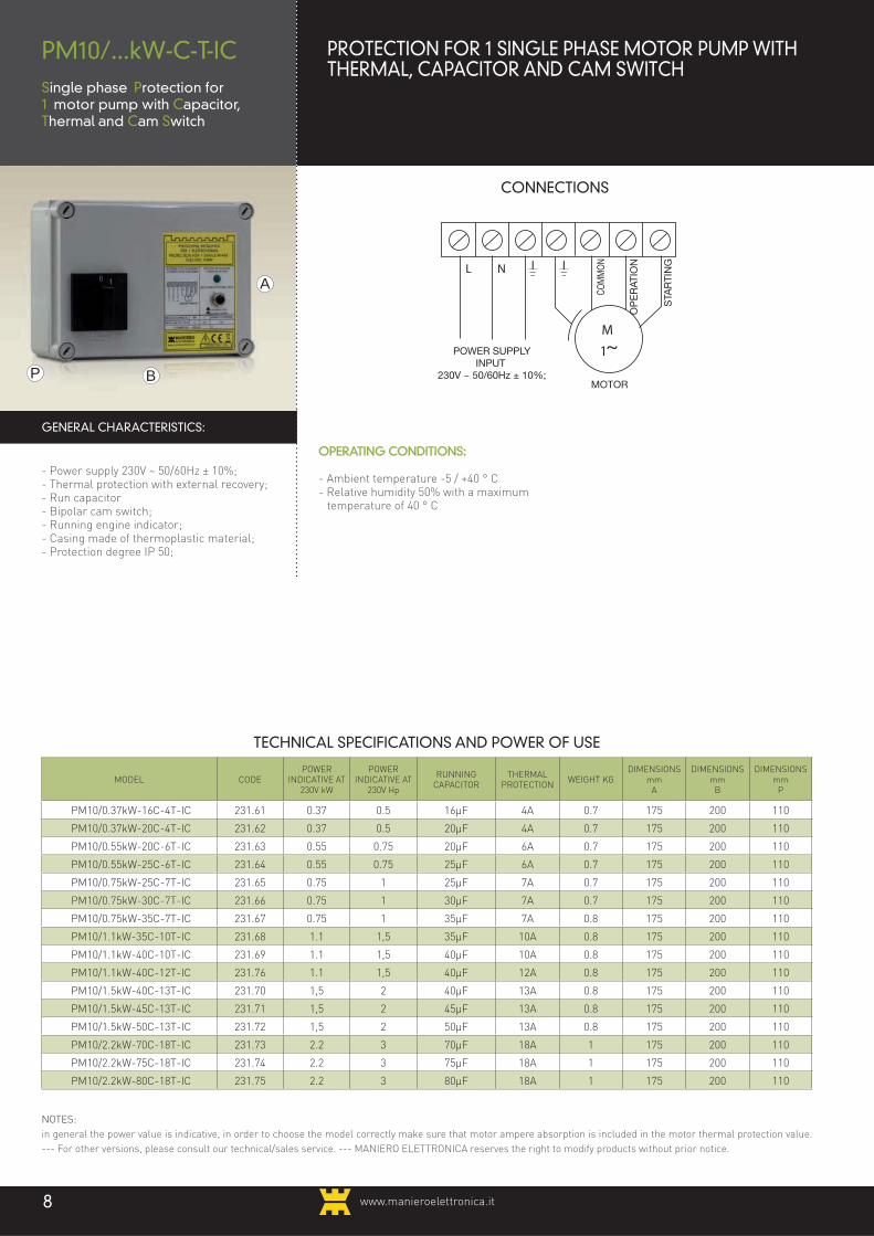
PROTECTION FOR 1 SINGLE PHASE MOTOR PUMP WITH THERMAL, CAPACITOR AND ILLUMINATED SWITCH
PM10/...kW-C-T-IL-2Single phase Protection for1 motor pump with Capacitor, Thermal and Illuminated Switch
The thermal protections offered are usually used to solve the problem of single-phase submersible pumps which need, in addition to thermal protection, also the specific start capacitor and on/off switch. The line protection (circuit breaker, etc...) is care of the installer.
TECHNICAL SPECIFICATIONS AND POWER OF USE
MODEL CODEPOWER
INDICATIVE AT 230V kW
POWER INDICATIVE AT
230V Hp
RUNNING CAPACITOR
THERMAL PROTECTION
WEIGHT KGDIMENSIONS
mmA
DIMENSIONS mm
B
DIMENSIONS mm
P
PM10/0,37kW-16C-4T-IL- 2 231.81 0.37 0.5 16μF 4A 0.5 210 115 70
PM10/0.37kW-20C-4T-IL- 2 231.82 0.37 0.5 20μF 4A 0.5 210 115 70
PM10/0.55kW-20C-6T-IL- 2 231.83 0.55 0.75 20μF 6A 0.5 210 115 70
PM10/0.55kW-25C-6T-IL- 2 231.84 0.55 0.75 25μF 6A 0.5 210 115 70
PM10/0.75kW-25C-7T-IL- 2 231.85 0.75 1 25μF 7A 0.5 210 115 70
PM10/0.75kW-30C-7T-IL- 2 231.86 0.75 1 30μF 7A 0.5 210 115 70
PM10/0.75kW-35C-7T-IL- 2 231.87 0.75 1 35μF 7A 0.5 210 115 70
PM10/1.1kW-35C-10T-IL- 2 231.88 1.1 1.5 35μF 10A 0.5 210 115 70
PM10/1.1kW-40C-10T-IL- 2 231.89 1.1 1.5 40μF 10A 0.5 210 115 70
PM10/1.1kW-40C-12T-IL- 2 231.90 1.1 1.5 40μF 12A 0.5 210 115 70
PM10/1.5kW-40C-13T-IL- 2 231.91 1.5 2 40μF 13A 0.5 210 115 70
PM10/1.5kW-45C-13T-IL- 2 231.92 1.5 2 45μF 13A 0.7 210 115 70
PM10/1.5kW-50C-13T-IL- 2 231.93 1.5 2 50μF 13A 0.7 210 115 70
IP55 PARTS:
- Switch cap, cod. 670.102;- Thermal cap cod. 879.276.
OPERATING CONDITIONS:
- Ambient temperature -5 / +40 ° C- Relative humidity 50% with a
maximum temperature of 40 ° C
STA
RTI
NG
OP
ER
ATIO
N
MOTOR
CO
MM
ON
CONNECTIONS
www.manieroelettronica.it 7
www.manieroelettronica.it
CONNECTIONS
8
NOTES:
in general the power value is indicative, in order to choose the model correctly make sure that motor ampere absorption is included in the motor thermal protection value.
--- For other versions, please consult our technical/sales service. --- MANIERO ELETTRONICA reserves the right to modify products without prior notice.
OPERATING CONDITIONS:
- Ambient temperature -5 / +40 ° C- Relative humidity 50% with a maximum
temperature of 40 ° C
GENERAL CHARACTERISTICS:
- Power supply 230V ~ 50/60Hz ± 10%;- Thermal protection with external recovery;- Run capacitor- Bipolar cam switch;- Running engine indicator;- Casing made of thermoplastic material;- Protection degree IP 50;
P B
A
PROTECTION FOR 1 SINGLE PHASE MOTOR PUMP WITHTHERMAL, CAPACITOR AND CAM SWITCH
PM10/...kW-C-T-ICSingle phase Protection for1 motor pump with Capacitor, Thermal and Cam Switch
TECHNICAL SPECIFICATIONS AND POWER OF USE
MODEL CODEPOWER
INDICATIVE AT 230V kW
POWER INDICATIVE AT
230V Hp
RUNNING CAPACITOR
THERMAL PROTECTION
WEIGHT KGDIMENSIONS
mmA
DIMENSIONS mm
B
DIMENSIONS mm
P
PM10/0.37kW-16C-4T-IC 231.61 0.37 0.5 16μF 4A 0.7 175 200 110
PM10/0.37kW-20C-4T-IC 231.62 0.37 0.5 20μF 4A 0.7 175 200 110
PM10/0.55kW-20C-6T-IC 231.63 0.55 0.75 20μF 6A 0.7 175 200 110
PM10/0.55kW-25C-6T-IC 231.64 0.55 0.75 25μF 6A 0.7 175 200 110
PM10/0.75kW-25C-7T-IC 231.65 0.75 1 25μF 7A 0.7 175 200 110
PM10/0.75kW-30C-7T-IC 231.66 0.75 1 30μF 7A 0.7 175 200 110
PM10/0.75kW-35C-7T-IC 231.67 0.75 1 35μF 7A 0.8 175 200 110
PM10/1.1kW-35C-10T-IC 231.68 1.1 1,5 35μF 10A 0.8 175 200 110
PM10/1.1kW-40C-10T-IC 231.69 1.1 1,5 40μF 10A 0.8 175 200 110
PM10/1.1kW-40C-12T-IC 231.76 1.1 1,5 40μF 12A 0.8 175 200 110
PM10/1.5kW-40C-13T-IC 231.70 1,5 2 40μF 13A 0.8 175 200 110
PM10/1.5kW-45C-13T-IC 231.71 1,5 2 45μF 13A 0.8 175 200 110
PM10/1.5kW-50C-13T-IC 231.72 1,5 2 50μF 13A 0.8 175 200 110
PM10/2.2kW-70C-18T-IC 231.73 2.2 3 70μF 18A 1 175 200 110
PM10/2.2kW-75C-18T-IC 231.74 2.2 3 75μF 18A 1 175 200 110
PM10/2.2kW-80C-18T-IC 231.75 2.2 3 80μF 18A 1 175 200 110
STA
RTI
NG
POWER SUPPLYINPUT
230V ~ 50/60Hz ± 10%;
OP
ER
ATIO
N
MOTOR
COM
MO
N

www.manieroelettronica.it 9
CONNECTIONS
TECHNICAL SPECIFICATIONS AND POWER OF USE
P B
A
CONTROLS AND SIGNALS
– Start and stop button.
CONTROLS AND SIGNALS
– Thermal relay sensitive to phase absence externally resettable.
GENERAL CHARACTERISTICS:
– Power 3 ~ 50/60Hz 400V ± 10%;– Contactor;– Protection degree IP65.
OPERATING CONDITIONS:
– Ambient temperature -5 / +40° C– Relative humidity 50% with
temperature maximum 40° C.
NOTES
– The power value is indicative in order for you to choose the correct control panel, make sure that the motor ampere absorption is included between the two operating current values of the control panel.
APPLICATIONS
• EMPTYING;
• FILLING;
• PRESSURIZATION.
MODEL CODE
CURRENTAPPLICATION
RECOMMENDED APPLICATIONS
WEIGHT
SIZE
NOTESSubmersible pumpsSurface Pumps
and general motorsA
HeightB
WidthP
Depth
(A) (kW) at 400V (kW) at 400V (kg) (mm) (mm) (mm)
PT10/1.5A-T-IMA 518.06 0,9 - 1,4 0.25 0.37 0.8 184 88 140 P
PT10/2A-T-IMA 518.08 1,3 - 2,1 0,55 0,75 0.8 184 88 140 P
PT10/3A-T-IMA 518.09 1,9 - 3 0,75 1.1 0.8 184 88 140 P
PT10/4.5A-T-IMA 518.10 2,9 - 4,5 1.1 1,5 0.8 184 88 140 P
PT10/7A-T-IMA 518.12 4,3 - 6,8 1,5 3 0.8 184 88 140 P
PT10/9A-T-IMA 518.13 5,7 - 9,1 3 4 0.8 184 88 140 P
PT10/14A-T-IMA 518.14 8,6 - 13,5 4 5,5 1 202 88 155 P
PT10/17A-T-IMA 518.15 12,5 - 16,5 5,5 7,5 1 202 88 155 P
PT10/21A-T-IMA 518.16 16 - 21 7,5 9 1.2 234 110 169 P
PT10/23A-T-IMA 518.17 19 - 23 9 11 1.2 234 110 169 P
PT10/29A-T-IMA 518.18 22 - 29 11 15 1.2 234 110 169 P
Tab.1
PT10/...A-T-IMA
Protection Three phase for 1motor pump with Thermal andSwitch Start and Stop
PROTECTION FOR 3-PHASE MOTOR PUMPWITH THERMAL PROTECTIONThe three-phase protection is proposed for all motor pump and motor needs with Start and stop push button and eventually connecting the neutral with the remote control 230V. The line protection (circuit breaker, etc...) is care of the installer.

www.manieroelettronica.it10
ELECTRONICCONTROL PANELS
"...We are all proudto build the successof the company... "

ELECTRONIC CONTROL PANELS FOX
A single control panel for multiple applications
• Emptying
• Filling
• Pressurization
A single philosophy for all motors
• Single and Three Phase
• Rated current from 1 to 400A
• All types of startup
• Groups 1 to 8 pumps
Easy to install and use
• Choosing the type of application
• Self-learning
• Start and stop buttons for each motor
• Status display motors and equipment
High performance
• Electronic protection motor current
• Electronic protection against dry running, with no probes
• Automatic control for frequent starts
• Self-diagnosis of the operation of float switches and pressure regulators
• Periodical unlocking of the impeller
• Regular emptying of the sludge deposited on the bottom
• Serial communication for remote management
SEE THE SPECIAL CATALOGUE FOX CONTROL PANELS
FOXTHE UNIVERSAL CONTROL PANEL
11

SMART ELECTRONIC CONTROL PANELS
A single control panel for multiple applications
• Emptying
• Filling
• Pressurization
A single philosophy for all motors
• Single and Three Phase
• Rated current from 1 to 200A
• All types of startup
• Groups 1 to 4 pumps
Easy to install and use
• Choosing the type of application
• Self-learning
• Start and stop buttons for each motor
• Status display motors and equipment
High performance
• Electronic protection motor current
• Electronic protection against dry running, with no probes
• Protection control phase sequence
• Automatic control for frequent starts
• Self-diagnosis of the operation of float switches and pressure switches
Optional
• Regular unlocking of the impeller (optional)
• Reversing the motor to release impeller (Optional)
• Serial and contact communication for remote management (optional)
SMARTTHE INTELLIGENT ELECTRIC CONTROL PANEL
www.manieroelettronica.it12

www.manieroelettronica.it 13
ONE - ELECTRONIC CONTROL PANELS
A single control panel for multiple applications
• Emptying
• Filling
• Pressurization
A single philosophy for 1 motor pump
• Single and Three Phase
• Rated current from 1 to 200A
• All types of startup
Easy to install and use
• Choosing the type of application
• Self-learning
• Motor start and stop buttons
• Status display motor and equipment
High performance
• Electronic protection motor current
• Electronic protection against dry running, with no probes
• Automatic control for frequent starts
• Inputs probes for minimum / maximum
level (self-learning of probe sensitivity)
• Protection control phase sequence (optional)
• Serial and contact communication for remote management (optional)
Quality
• Guarantee of a trademark
• Over 40 years of experience in the field
• ISO 9001:2008 certified company
ONETHE UNIQUE ELECTRIC CONTROL PANEL

www.manieroelettronica.it14
− The control panels belong to the "SMART" series
and are suitable for a wide range of applications, the
main area is water treatment such as:
• Emptying;
• Filling;
• Pressurization;
− The control panels belonging to the "SMART" series
concentrate into a single product. The basic and
single auxiliary functions are useful in all kinds of
applications, while remaining open to integration
with other devices to best fit all kinds of needs.
− The "heart" of the control panels belonging to the
"SMART" series consists of a microprocessor board
that controls all the functions and its modular
hardware and software structure, allows the making
of control panels which control and operate in a
global and coordinated manner
• From 1 to 4 motors;
• Single and three phase motors with direct starter
type;
• Three-phase motors with Wye-Delta starter type,
Reactance;
• Motors with a nominal current from 1A to 200A.
− The SELF-LEARNING and ELECTRONIC CONTROL
function of the CURRENT and COS , protect
effectively each motor and offer a timely diagnosis
in case anomalies should occur. Each control panel
is equipped with a serial communication system,
through which you can connect a control system
both locally and remotely (remote control) to indicate
the status of inputs and outputs, to measure the
current and the phase of each motor, and the
presence of alarms if any.
− The terminals for the control devices (floats,
pressure regulators, thermistors, outputs for
alarm signals) and power (power supply input,
motor outputs) are well identified and accessible to
facilitate wiring at installation.
− Signaling is made by LED indicator lights which
inform about general state of the system and the
single status of each engine.
− The controls are independent for each motor and are
operated by buttons.
− The use of buttons and indicator lights of the reading
is made simple and intuitive because they are
individually identified by a symbol and an inscription
engraved in the membrane.
− The membrane also covers lights and buttons, thus
ensuring a high degree of protection (IP55).
− In the larger size models, controls, and signals are
made with buttons and indicator lights Ð 22mm.
− The control panels belonging to the "SMART" series
are the result of our continuous research and
experience accumulated in over 40 years in the field
of control panels for water treatment.
GENERAL CHARACTERISTICS: Comparison of the features SMART and FOX
FEATURE FOX SMART ONE
Adjustable functions
Applications: emptying, filling, pressurization
Alternating motor Starting type based on the number of starts
Alternating motor Starting type based on work time
Delayed motor Starting
Delayed motor shut-down
Auto retaining for motor stop from level float min/max
Maximum level alarm management
Aspiration if sludge (only emptying)
Periodical unlocking of the impeller
Electronic protection against dry running, with no probes
Maximum number of hourly Startings
Access restrictions to the use of command buttons
Parameters for Modbus RTU communication
Self-learning of motor data
Setting the threshold for triggering of overload motor protection
Sensor inputs with self-learning
Alarms and protections
Shutdown and alarm for:
Dry running with periodical reset attempt
Over current
Current imbalance between phases
Minimum load (motor too small or not connected)
Defective electromechanical starter (stuck contactor)
Defective electromechanical starter (defective timer for Wye-Delta starting, Reactance, or soft start)
Minimum or maximum emergency level
Alarm level or maximum pressure
Detection of auxiliary device tripping
Malfunction of float or pressure switches
Maximum number of hourly Startings
Motor over temperature
Infiltration of water into the oil chamber in motors with built-in probe
LEGEND:
PresentFixedOptional
www.manieroelettronica.it 15
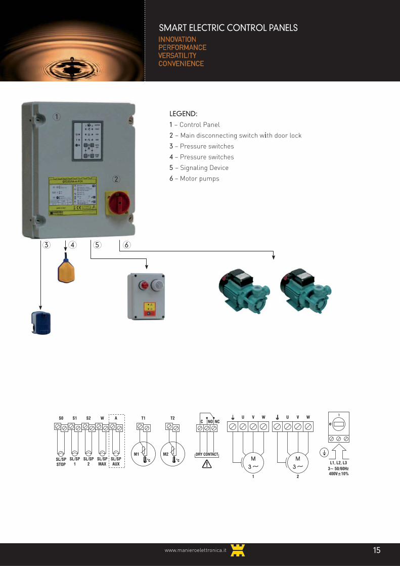
SMART ELECTRIC CONTROL PANELSINNOVATION
PERFORMANCE
VERSATILITY
CONVENIENCE
LEGEND:
1 – Control Panel
2 – Main disconnecting switch with door lock
3 – Pressure switches
4 – Pressure switches
5 – Signaling Device
6 – Motor pumps
1
2
3 4 5 6
U V W
1
3~ 50/60Hz 400V±10%
L1, L2, L3
U V W
2
SL/SPSTOP
SL/SP1
SL/SP2
SL/SPMAX
SL/SPAUX
M1 DRY CONTACT
S0 S1 S2 W ANO
°c
T1NCC
M2
T2
°c

www.manieroelettronica.it16
− Control panel for 1 -4 motor pumps; − Power supply (depending on model):• ~ 230V 50/60Hz (240V on request) ± 10%;• 3 ~ 230V 50/60Hz (240V on request) ±
10%;• 3 ~ 400V 50/60Hz (415V on request) ±
10%; − Main disconnecting switch with door lock; − Thermoplastic or metal casing; − Protection degree IP55;
POWER SECTION
− No. 1 to 4 motor outputs type (depending on model):• Single phase;• Three phase;
− Motor starting type (depending on model):• Direct;• Wye-Delta;• Reactance.
CONTROL INPUT AND OUTPUT
− No. 3 low voltage inputs for float or pressure switch of:• Minimum or maximum level detection
(SL / SP STOP);• Level detection or maximum alarm
pressure (SL / SP MAX);• Detection operation auxiliary device (SL
/ SP AUX); − Extra low voltage input to float or
pressure switch to control each motor (SL / SP 1, 2, ...).
− Extra low voltage isolated input, for detection sensor of each motor.
− Relay output with changeover contact N.O. / N.C. alarm (250V ~ 5A max
− resistive charge).
CONTROLS AND SIGNALS
− No. 2 buttons for each motor for operation:• AUTO / RESET alarm;• OFF / MANUAL;
− No. 3 indicator lights for the signaling of:• Presence and / or power failure;• Alarm pressure switch or float tripping
or malfunction of the sensors (pressure switches or floats);
• Float or minimum / maximum shutoff pressure switch or auxiliary device tripping;
− No. 3 indicator lights for each motor for the signaling of:• Operation in AUTO / OFF / MANUAL;• Motor in operation or motor stop due
to dry operation, or motor stopped due to maximum number of Startings individually distinguishable;
• Protection tripped due to over current, unbalanced current, motor not connected, electromechanical starter fault, motor over temperature individually distinguishable;
FUNCTIONS SET BY SELECTORS
− Application:• Emptying;• Filling;• Pressurization;
− Additional functions:• Alternating motor Starting type based on
the number of starts;• Delayed motor Starting• Auto retaining due to motor shut-down
only with minimum level (emptying only) / maximum level (filling only) float;
• Reversing polarity of the level input or minimum pressure (pressurization only);
• Alarms and reports;• Unlocking of the impeller;
− Protections:• Monitoring of phase sequence of supply
voltage;• Electronic protection against dry
running;• Maximum number of hourly Startings;• Access restrictions to the use of
command buttons.
FUNCTIONS TO BE SET BY POTENTIOMETERS
− Self-learning of motor data (only during commissioning);
− Setting the threshold for triggering of overload motor protection;
GENERAL FEATURES
− Delay for motor Starting after the restoration of power supply;
− Non contemporaneous starting and stopping of the motor pumps;
− Motor exchange for extended operation; − "MANUAL" operation type:• "PERMANENT" by briefly pressing the
command button;• Operation is subject to arrest by
minimum or maximum level (float SL / SP STOP);
• "TEMPORARY" maintained by pressing the command button;
• Operation is not subject to arrest by minimum or maximum level (float SL / SP STOP);
PROTECTION AND ALARMS
− Shutdown and alarm on the triggering of the electronic protection for each motor for:• Dry running with periodical reset
attempt;• Over current;• Current imbalance between phases;• Minimum load (motor too small or not
connected);• Defective electromechanical starter
(stuck contactor) − Motor shutdown and warning alarm for
detection of:• Minimum or maximum level;• Maximum Alarm pressure or level;• Detection of auxiliary device tripping
(optional);• Malfunction of float or pressure
switches;• Maximum number of hourly Startings;• Motor over temperature;
− Motor protection fuses; − Protection fuses on the auxiliary circuits; − Safety transformer for extra low voltage
circuits.
FUNCTIONS WITH OPTIONAL MODULES
− Detection operation auxiliary device (SL / SP AUX);
− Reversing the motor with a manual command;
− Communication on RS-485 line and Modbus RTU protocol;
− Control of power supply voltage for over / under voltage;
− Level probes; − External or integrated buzzer; − External or integrated blinking warning
light.
OPERATING CONDITIONS:
− Ambient temperature -5 / +40 ° C − Maximum relative humidity 50% with
maximum temperature +40°C.
GENERAL CHARACTERISTICS:
SMART ELECTRIC CONTROL PANELSINNOVATION
PERFORMANCE
VERSATILITY
CONVENIENCE

www.manieroelettronica.it 17
MODEL CODE
OPERATING CURRENT
(Of each engine)RECOMMENDED APPLICATIONS
WEIGHT
DIMENSIONS
NOTESMIN MAX
Motor
minimum
power
Submersible
pump
Surface
pumps and
generic
motors
AHeight
BWidth
PDepth
(A) (A) (kW) (kW) (kW) (kg) (mm) (mm) (mm)
QMD20/17A-A-SMART 527.51 1 17 0.09 2.2 4 460 380 160 P
TECHNICAL SPECIFICATIONS AND POWER OF USE
QMD20/...AA-SMART Control panel for 2 motor pumps with single phase direct starting motor with electronic current protection, power supply 230V (240V on request)
MODEL CODE
OPERATING CURRENT
(Of each engine)RECOMMENDED APPLICATIONS
WEIGHT
DIMENSIONS
NOTESMIN MAX
Motor
minimum
power
Submersible
pump
Surface
pumps and
generic
motors
AHeight
BWidth
PDepth
(A) (A) (kW) (kW) (kW) (kg) (mm) (mm) (mm)
QTD20/9A-A-SMART 527.63 1 9 0.25 3 4 5.5 385 305 160 P
QTD20/17A-A-SMART 527.65 1 17 0.25 5.5 7.5 5.5 385 305 160 P
QTD20/23A-A-SMART 527.67 2 23 0.75 7.5 11 5.5 385 305 160 P
QTD20/29A-A-SMART 527.68 2 29 0.75 11 15 7.5 460 380 160 P
QTD20/35A-A-SMART 527.69 2 35 0.75 15 18.5 7.5 460 380 160 P
TECHNICAL SPECIFICATIONS AND POWER OF USE
QTD20/...AA-SMART Control panel for 2 motor pumps with three phase direct starting motor with electronic current protection, power supply 3 ~ 400V (415V on request)
~ 50/60Hz 230V±10%
L1NC
(1)
1
(2)
L1NC
(1)
2
(2)
L, NSL/SPSTOP
SL/SP1
SL/SP2
SL/SPMAX
SL/SPAUX
M1 DRY CONTACT
S0 S1 S2 W ANO
°c
T1NCC
M2
T2
°c
U V W
1
3~ 50/60Hz 400V±10%
L1, L2, L3
U V W
2
SL/SPSTOP
SL/SP1
SL/SP2
SL/SPMAX
SL/SPAUX
M1 DRY CONTACT
S0 S1 S2 W ANO
°c
T1NCC
M2
T2
°c
CONNECTIONS
CONNECTIONS
SMART ELECTRIC CONTROL PANELSINNOVATION
PERFORMANCE
VERSATILITY
CONVENIENCE

PROTECTION DEGREE IP 55 OPTIONAL:
– Switch cap, cod. 644.344;
– Thermal cap cod. 879.276.
GENERAL CHARACTERISTICS:
– Control panel with electronic components;– Power supply 230V ~ 50/60Hz ± 10%;– Extra low voltage input for external control from
pressure switch or switch of the floating type;– Extra low voltage input for pressure switch or
minimum float to prevent dry operation or too full;
– Selector switch for pressure switch or minimum float (NC or NO contacts);
– LED indicator for network presence;– LED indicator running engine;– LED indicator alarm level, min / max water;– Selector for automatic-manual-off (the latter
P B
A
MODEL CODEPOWER
INDICATIVE AT 230V kW
POWER INDICATIVE AT
230V Hp
THERMAL PROTECTION
WEIGHT KGDIMENSIONS
mmA
DIMENSIONS mm
B
DIMENSIONS mm
P
QMD10/0.37kW-4T 232.21 0.37 0.5 4A 1.5 225 255 130
QMD10/0.55kW-6T 232.22 0.55 0.75 6A 1.5 225 255 130
QMD10/0.75kW-7T 232.23 0.75 1 7A 1.5 225 255 130
QMD10/1.1kW-10T 232.24 1.1 1.5 10A 1.5 225 255 130
QMD10/1.5kW-13T 232.25 1.5 2 13A 1.5 225 255 130
QMD10/2.2kW-18T 232.26 2.2 3 18A 1.5 225 255 130
* AMD10/0.37kW-4T 232.01 0.37 0.5 4A 0.8 180 200 100
* AMD10/0.55kW-6T 232.02 0.55 0.75 6A 0.8 180 200 100
* AMD10/0.75kW-7T 232.03 0.75 1 7A 0.8 180 200 100
* AMD10/1.1kW-10T 232.04 1.1 1.5 10A 0.8 180 200 100
* AMD10/1.5kW-13T 232.05 1.5 2 13A 0.8 180 200 100
* AMD10/2,2kW-18T 232.06 2.2 3 18A 0.8 180 200 100
TECHNICAL SPECIFICATIONS AND POWER OF USE
NOTES:
in general the power value is indicative, in order to choose the model correctly make sure that motor ampere absorption is included in the motor thermal protection value.
CONTROL PANELS AND STARTERS FOR 1 SINGLE PHASE MOTOR PUMP 230V WITH THERMAL PROTECTION
QMD10/...kW-TDirect Single phase Control panel for 1 motor pump with Thermal protection
The single phase control panels for the steering and protection of motor pumps are available with thermal protection or with ammetric protection The ammetric protection allows to cover with a single model across the range with power from 0.37 kW to 2.2 kW. NOTE: If more pumps are needed, contact our technical/sales department.
FLOATS OR PRESSURESWITCHES
POWER SUPPLY INPUT230V ~ 50/60Hz ± 10%
MOTOR
OPER
ATIO
N
ELECTRONIC SPARE PARTS:
– Motherboard, cod. 22331;
– Synoptic panel, cod. 316.06.
OPERATING CONDITIONS:
– Ambient temperature -5 / +40 ° C
– Relative humidity 50% with a maximum
temperature of 40 ° C
command has an automatic return);– Main disconnecting switch with door lock;– Thermal protection with external recovery;– Motor protection fuse;– Casing made of thermoplastic material;– Protection degree IP 50;
* GENERAL CHARACTERISTICS: the features and the conditions of service are identical to the series QMD10/...kW-T (see above) but without the "door interlock main disconnector."
1 EL
ECTR
ON
IC P
UM
P
www.manieroelettronica.it18

CONNECTIONS
A
BP
MODEL CODEPOWER
INDICATIVE AT 230V kW
POWER INDICATIVE AT
230V Hp
RUNNING CAPACITOR
THERMAL PROTECTION
WEIGHT KGDIMENSIONS
mmA
DIMENSIONS mm
B
DIMENSIONS mm
P
QMD10/0.37kW-16C-4T 232.61 0.37 0.5 16μF 4A 1.6 225 255 130
QMD10/0.37kW-20C-4T 232.62 0.37 0.5 20μF 4A 1.6 225 255 130
QMD10/0.55kW-20C-6T 232.63 0.55 0.75 20μF 6A 1.6 225 255 130
QMD10/0.55kW-25C-6T 232.64 0.55 0.75 25μF 6A 1.6 225 255 130
QMD10/0.75kW-25C-7T 232.65 0.75 1 25μF 7A 1.6 225 255 130
QMD10/0.75kW-30C-7T 232.66 0.75 1 30μF 7A 1.6 225 255 130
QMD10/0.75kW-35C-7T 232.67 0.75 1 35μF 7A 1.6 225 255 130
QMD10/1.1kW-35C-10T 232.68 1.1 1.5 35μF 10A 1.6 225 255 130
QMD10/1.1kW-40C-10T 232.69 1.1 1.5 40μF 10A 1.6 225 255 130
QMD10/1.5kW-40C-13T 232.70 1.5 2 40μF 13A 1.6 225 255 130
QMD10/1.5kW-45C-13T 232.71 1.5 2 45μF 13A 1.6 225 255 130
QMD10/1.5kW-50C-13T 232.72 1.5 2 50μF 13A 1.6 225 255 130
QMD10/2.2kW-70C-18T 232.73 2.2 3 70μF 18A 1.8 225 255 130
QMD10/2.2kW-75C-18T 232.74 2.2 3 75μF 18A 1.8 225 255 130
QMD10/2.2kW-80C-18T 232.75 2.2 3 80μF 18A 1.8 225 255 130
* AMD10/0.37kW-16C-4T 232.41 0.37 0.5 16μF 4A 1 180 200 100
* AMD10/0.37kW-20C-4T 232.42 0.37 0.5 20μF 4A 1 180 200 100
* AMD10/0.55kW-20C-6T 232.43 0.55 0.75 20μF 6A 1 180 200 100
* AMD10/0.55kW-25C-6T 232.44 0.55 0.75 25μF 6A 1 180 200 100
* AMD10/0.75kW-25C-7T 232.45 0.75 1 25μF 7A 1 180 200 100
* AMD10/0.75kW-30C-7T 232.46 0.75 1 30μF 7A 1 180 200 100
* AMD10/0.75kW-35C-7T 232.47 0.75 1 35μF 7A 1 180 200 100
* AMD10/1.1kW-35C-10T 232.48 1.1 1.5 35μF 10A 1 180 200 100
* AMD10/1.1kW-40C-10T 232.49 1.1 1.5 40μF 10A 1 180 200 100
* AMD10/1.5kW-40C-13T 232.50 1.5 2 40μF 13A 1 180 200 100
* AMD10/1.5kW-45C-13T 232.51 1.5 2 45μF 13A 1 180 200 100
* AMD10/1.5kW-50C-13T 232.52 1.5 2 50μF 13A 1 180 200 100
* AMD10/2.2kW-70C-18T 232.53 2.2 3 70μF 18A 1.5 225 255 115
* AMD10/2.2kW-75C-18T 232.54 2.2 3 75μF 18A 1.5 225 255 115
* AMD10/2.2kW-80C-18T 232.55 2.2 3 80μF 18A 1.5 225 255 115
TECHNICAL SPECIFICATIONS AND POWER OF USE
CONTROL PANELS AND STARTERS FOR 1 SINGLE PHASE MOTOR PUMP 230V WITH THERMAL PROTECTION AND CAPACITOR
QMD10/...kW-C-TDirect Single phase Control panel for 1 motor pump with Capacitor and Thermal protection
FLOATS OR PRESSURESWITCHES
POWER SUPPLY INPUT~50/60Hz 230V ± 10%
MOTOR
OPER
ATIO
N
STAR
TING
COM
MON
* GENERAL CHARACTERISTICS: the features and the conditions of service are identical to the series QMD / T-...kW on page 6 but without the "door interlock main disconnector" and with the addition of the "run capacitor".
1 EL
ECTR
ON
IC P
UM
P
GENERAL CHARACTERISTICS:
– Control panel with electronic components;– Power supply 230V ~ 50/60Hz ± 10%;
– Run capacitors sized according to the power of the engine;
- Extra low voltage input for external command from pressure or float switch;
– Extra low voltage input for minimum pressure switch or float against dry operation or too full;
– Selector for pressure switch or minimum float (NC or NO contacts);
– LED indicator for network presence;– LED indicator running engine;– LED indicator alarm level, min / max
water;– Selector for automatic-manual-off
(the latter command has an automatic return);
– Main disconnecting switch with door lock;
– Thermal protection with external reset;– Motor protection fuse;– Casing made of thermoplastic material;– Protection degree IP 50;
6919www.manieroelettronica.it

www.manieroelettronica.it20
P B
A
READY FOR THE APPLICATION OF:
– KCC/...: Kit capacitor wired (Optional, depending on motor used) (see
SEC. 8 - ACCESSORIES FOR CONTROL PANELS
– MIC/1E-..V-2U in 3 versions (See SEC. 7 - ADDITIONAL EQUIPMENT):
interface module for control from an external device with power supply with 12V or 24V ~ ~ ~ or 230V clean output contacts.
NOTE: you can use instead ofthe probes No. 2 float switches 1 OFF and 1
ON.
PROTECTION DEGREE IP 55 OPTIONAL:
– Switch cap, cod. 644.344;– Button cap, cod. 644.345 (for model AA/50B).
GENERAL CHARACTERISTICS:
– Control panel with electronic components;– Power supply 230V ~ 50/60Hz ± 10%;– Extra low voltage input for external control from
pressure switch or float switch;– Extra low voltage input for probes, pressure
switch or minimum float against dry operation or too full;
– Selector switch for pressure switch or minimum float (NC or NO contacts) or in the case of probes for FILLING OR EMPTYING;
– LED light motor running (on) or motor protection (flashing);
– Selector switch for off-automatic-manual operation (this command has an automatic return
– Electronic protection with adjustable current;– Time Trip Delay Protection approximately 3s;– Motor protection fuses;– Main disconnecting switch with door lock;– Casing made of thermoplastic material;– Protection degree IP 50.
NOTES:
in general the power value given is indicative. In order to choose the control panel correctly make sure that motor ampere absorption is included between the two operating
current values of the control panel.
For other versions, please consult our technical / business department.
MANIERO ELETTRONICA reserves the right to modify products without prior notice.
The application of modules can lead to changes in the size of the casing and the cost of the control panel.
CONTROL PANELS AND STARTERS FOR ONE SINGLE PHASE MOTOR PUMP 230 V WITH AMMETRICPROTECTION AND LEVEL CONTROL
QA/50BSingle phase Control panelDirect for 1 motor pumpup to 2.2 kW Ammetricprotection
ELECTRONIC SPARE PARTS:
– Motherboard, cod. 31316;– Synoptic panel:
QA/50B 20 31604; AA/50B, cod. 316.14.
OPERATING CONDITIONS:
– Ambient temperature -5 / +40 ° C– Relative humidity 50% with a maximum
temperature of 40 ° C
POWER SUPPLY INPUT ~ 50/60Hz ± 10%MOTORLEVEL PROBES
OPER
ATIO
N
STAR
TING
COM
MON
TECHNICAL SPECIFICATIONS AND POWER OF USE
* GENERAL CHARACTERISTICS: Features, arrangements, parts and service conditions are identical to the series QA/50B but without the "door interlock main disconnector."
1 EL
ECTR
ON
IC P
UM
P
CONNECTIONS
MODEL CODEPOWER
INDICATIVE AT 230V kW
POWER INDICATIVE AT
230V Hp
OPERATING CURRENT (A)
MIN
OPERATING CURRENT (A)
MAXWEIGHT KG
DIMENSIONS mm
A
DIMENSIONS mm
B
DIMENSIONS mm
P
QA/50B 233.13 0,37 - 2,2 0,5 - 3 2 18 1.5 220 255 130
* AA/50B 233.03 0,37 - 2,2 0,5 - 3 2 18 1.5 220 255 115

www.manieroelettronica.it 21
CONNECTIONS
READY FOR THE APPLICATION OF:
– MIC/1E-..V-2U in 3 versions (see see SEC. 7 -
ADDITIONAL EQUIPMENT): interface module for control
from an external device with power supply with 12V or 24V ~ ~ ~ or 230V clean output contacts.
For models QA/60C QA/61C it involves the change of housing.
NOTE: you can use instead ofthe probes No. 2 float switches 1 OFF and 1
ON.
GENERAL CHARACTERISTICS:
– Electronic control panel;– Power 3 ~ 50/60Hz 400V ± 10%;– Extra low voltage input for external command
from pressure switch or float switch;– Extra low voltage inputs for probes, pressure
switch or minimum float switch against dry running or too full;
– Selector for level probes (contacts NC for EMPTYING or NO for FILLING);
– Selectors to full scale adjustment trimmer for regulation of probe tripping threshold (2-20K, 10-100K);
– Trimmer for adjustment of the tripping threshold of the probes;
– Trimmer for the adjustment ammetric protection (overload) activation: the time of delay is approx. 3 sec;
– Selector switch for OFF-AUTOMATIC-MANUAL operation (this command has an automatic return);
– LED light motor running (on) or motor protection (flashing).
– Motor protection fuses;
P B
A
QA/60CThree phase Direct Start Control panel for 1 motor pump with Ammetric protection
CONTROL PANELS AND STARTERS FOR 1 THREE PHASE MOTOR PUMP WITH DIRECT STARTING AND OVERLOADAMMETRIC PROTECTION AND LEVEL CONTROL
TECHNICAL SPECIFICATIONS AND POWER OF USE
MODEL CODEPOWER
INDICATIVE AT 400V kW
POWER INDICATIVE AT
400V Hp
OPERATING CURRENT
(A) MIN
OPERATING CURRENT (A)
MAXWEIGHT KG
DIMENSIONS mm
A
DIMENSIONS mm
B
DIMENSIONS mm
P
QA/60C 235.75 0,55 - 3,7 0,75 - 5 2 8 1.8 200 255 130
QA/61C 235.76 0,55 - 5 0,75 - 7 2 11 1.9 200 255 130
QA/62C 235.77 0,55 - 7 0,75 - 9,5 2 16 2.7 240 315 160
QA/63C 235.78 7,5 - 10 10 - 14 16 22 2.8 240 315 160
QA/64C 235.79 7,5 - 13,5 10 - 18 16 29 2.8 240 315 160
QA/65C 235.80 7,5 - 16 10 - 22 16 34 4 400 315 165
The AA/6...C version is available with the same characteristics of the model QA/6...C but without the "door interlock disconnect switch."
To order, please contact our technical/sales department.
– Auxiliary circuits protection fuses;– Main disconnecting switch with door lock;– Casing made of thermoplastic material;– Protection degree IP 50
PROTECTION DEGREE IP 55 OPTIONAL:
– Switch cap, cod. 644.344;– Button cap, cod. 644.345 (For models AA).
ELECTRONIC SPARE PARTS:
– For models QA/60C, QA/61C, QA/62C: • Motherboard cod. 22351;– For models QA/63C, QA/64C, QA/65C: • Motherboard cod. 22361;– Synoptic panel code. 316.04.
OPERATING CONDITIONS:
– Ambient temperature -5 / +40 ° C– Relative humidity 50% with a maximum
temperature of 40 ° C
POWER SUPPLY INPUT 400V ~ 50/60Hz ± 10%MOTORLEVEL PROBES
1 EL
ECTR
ON
IC P
UM
P

www.manieroelettronica.it22
CONNECTIONS
The module allows the extension of the application as shown in the general characteristics listed below:
READY FOR THE APPLICATION OF:
To expand the features of the control panel QMD20/...kW-T-SI-2;
– MSM/Q20-SI-2 cod. 221.80 (See below);– MA/1-100 cod. 221.70 (see SEC. 7 -
ADDITIONAL EQUIPMENT) if present MSM/Q20-SI-2.
PROTECTION DEGREE IP 55 OPTIONAL:
– No. 2 switch caps, cod. 644,344;– No. 2 thermal caps cod. 879.276.
ELECTRONIC SPARE PARTS:
– Motherboard, cod. 219.66;– Synoptic panel, cod. 316.12.
MSM/Q20-SI-2
TECHNICAL SPECIFICATIONS AND POWER OF USE
MODEL CODE
POWER INDICATIVE AT
230V (FOR EACH SINGLE
ENGINE)
kW
POWER INDICATIVE AT
230V (FOR EACH SINGLE
ENGINE)
Hp
THERMALPROTECTION
WEIGHT KGDIMENSIONS
mmA
DIMENSIONS mm
B
DIMENSIONS mm
P
QMD20/0.37kW-4T-SI-2 245.31 0.37 0.5 4A 1.6 265 200 130
QMD20/0.55kW-6T-SI-2 245.32 0.55 0.75 6A 1.6 265 200 130
QMD20/0.75kW-7T-SI-2 245.33 0.75 1 7A 1.6 265 200 130
QMD20/1.1kW-10T-SI-2 245.34 1.1 1.5 10A 1.6 265 200 130
QMD20/1.5kW-13T-SI-2 245.35 1.5 2 13A 1.6 265 200 130
QMD20/2.2kW-18T-SI-2 245.36 2.2 3 18A 1.6 265 200 130
integrated on-board (can be disabled via micro switches);
– Non simultaneous starting of the motors;– LED indicator for network presence;– LED indicator alarm level, min / max water;– No. 2 LED motor running indicators;– Selector switch for off-automatic-manual
operation (this command has an automatic return);
– Thermal protection on each motor externally resettable;
– Auxiliary circuits protection fuse;– Motor protection fuses;– Main disconnecting switch with door lock;– Casing made of thermoplastic material;– Protection degree IP 50
GENERAL CHARACTERISTICS:
– Control panel with electronic components;– Power supply ~50/60Hz 220...240Vca ± 10%;– Extra low voltage input for external control
from pressure switch or float switches;– Extra low voltage inputs for pressure switch
or minimum float switch against dry running or too full;
– Micro selector switch for pressure switch or minimum float (NC or NO contacts);
– Delayed action SL/SP2 from 0 to 4s selectable via micro switches;
– 0.5 s delay to avoid repeated switching operations due to the fluctuations of the float switches;
– Changeover circuit motor starting sequence
Motherboard Module for Control Panels with 2 motor pumps with Integrated Exchanger
P B
A
QMD20/...kW-T-SI-2Direct Start Single phase Control panel for 2 motor pumps with Thermal Protection and IntegratedExchanger
CONTROL PANELS AND STARTERS FOR 2 SINGLE PHASE MOTOR PUMPS 230V WITH THERMAL PROTECTION AND EXCHANGER INTEGRATED (ON MOTHERBOARD)
The AMD20/..KW-T-SI-2 version is available with the same characteristics of the model QMD20 but without the "door interlock disconnect switch."To order, please contact our technical/sales department.
GENERAL CHARACTERISTICS:
– Shunting delay of SL/SP1 and SL/SP2 from 3 to 60s via micro switches on the motherboard;
– Operating mode selector with bulb floats
(SL1 and SL2 switch on the motors while SL shuts them down);
– Detecting thermal protection intervention;– Activation of the second motor if the one
running stops due to
thermal protection tripping (only if changeover is enabled);
– Supplied with mounting turrets.
MSM/Q20-SI-2 cod.221.80
FLOATS OR PRESSURE SWITCHES POWER SUPPLY INPUT~ 50/60Hz 220…240V±10%
MOTOR1
MOTOR2
OPER
ATIO
N
COM
MON
OPER
ATIO
N
COM
MON
2 EL
ECTR
ON
IC P
UM
PS

www.manieroelettronica.it 23
CONNECTIONS
PROTECTION DEGREE IP 55 OPTIONAL:
– No. 2 switch caps, cod. 644.344.
ELECTRONIC SPARE PARTS:
– Motherboard, cod. 223.71;– Synoptic panel, cod. 316.11.
OPERATING CONDITIONS:
– Ambient temperature -5 / +40 ° C
– Relative humidity 50% with a maximum
temperature of 40 ° C
– Fuse protection for each motor;– Auxiliary circuits protection fuse;– Main disconnecting switch with door lock;– Casing made of thermoplastic material;– Protection degree IP 50
GENERAL CHARACTERISTICS:
– Control panel with electronic components;– Power 3 ~ 50/60Hz 400V ± 10%;– Extra low voltage input for external control
from pressure switch or float switches;– Extra low voltage input for external control
from pressure or minimum float switch (contact NO) against dry running or too full;
– Changeover circuit motor starting sequence integrated on-board
– No. 2 LED motor running indicators;– No. 2 LED motor protection indicators;Selector switch for off-automatic -manual
operation (this command has an automatic return);
– Contactors with thermal relays internally resettable;
CONTROL PANELS AND STARTERS FOR 2 THREE PHASE MOTOR PUMPS WITH DIRECT STARTING AND THERMAL PROTECTION AND INTEGRATED EXCHANGER
QTD20/...kW-T-SIThree phase Direct Start Control panel for 2 motor pumps withThermal protection and Integrated Exchanger
P B
A
TECHNICAL SPECIFICATIONS AND POWER OF USE
The ATD20/...kW-T-SI version is available with the same characteristics of the model QTD20/...kW-T-SI but without the "door interlock
disconnect switch." To order, please contact our technical/sales department.
FLOATS OR PRESSURESWITCHES
POWER SUPPLYINPUT
3 ~ 50/60Hz 400V±10%MOTOR
1MOTOR
2
2 EL
ECTR
ON
IC P
UM
PS
MODEL CODE
POWER INDICATIVE AT 400V (FOR EACH
SINGLE ENGINE)
kW
POWER INDICATIVE AT 400V (FOR EACH
SINGLE ENGINE)
Hp
CURRENTFOR OPERATION (A) (FOR EACH MOTOR)
MIN
OPERATION CURRENT (A) (FOR EACH MOTOR)
MAX
WEIGHT KGDIMENSIONS
mmA
DIMENSIONS mm
B
DIMENSIONS mm
P
QTD20/0.37kW-T-SI 245.81 0.37 0.5 0.9 1.3 4 340 235 160
QTD20/0.55kW-T-SI 245.82 0.55 0.75 1.4 1.9 4 340 235 160
QTD20/1.1kW-T-SI 245.83 0,75 - 1,1 1 - 1,5 2 3 4 340 235 160
QTD20/1,5kW-T-SI 245.84 1.5 2 3 4.5 4 340 235 160
QTD20/2.2kW-T-SI 245.85 1,8 - 2,2 2,5 - 3 4.5 5.8 4 340 235 160
QTD20/3.7kW-T-SI 245.86 3 - 3,7 4 - 5 6 8 4 340 235 160
QTD20/5,5kW-T-SI 245.87 4 - 5,5 5,5 - 7,5 9 13.5 4 340 235 160
QTD20/7kW-T-SI 245.88 6 - 7 8 - 9,5 14 18 4.5 420 315 165
QTD20/10kW-T-SI 245.89 7,5 - 10 10 - 14 17 22 5.5 420 315 165
QTD20/13,5kW-T-SI 245.90 11 - 13,5 15 - 18 20 29 5.5 420 315 230
QTD20/16kW-T-SI 245.91 15 - 16 20 - 22 28 35 5.5 550 400 230

www.manieroelettronica.it24
CONNECTIONS
CVE...2Expansion VesselsControl
The system consists of the master control unit which contains an electronic unit a PLC and touch screen, a compressor unit, the electromechanical control components and the pneumatic unit. The system also includes the load cell and the supports for vessels available on the market. The control system consists of a constant pressure control to be coupled to an expansion vessel and designed to govern large heating systems (hotels, buildings, sheds, greenhouses, etc..). The system allows to achieve significant results in terms of control , functionality and savings.
A
BP
TECHNICAL CHARACTERISTICS
MODEL CODE
COMPRESSOR
WEIGHT
SIZE
NOTESPowerMaximum Pressure
Air output
NoiseA
HeightB
WidthP
Depth
(kW) (bar) (Lt/min) (dB) (kg) (mm) (mm) (mm)
CVEM2/1000 530.01 0.75 8 105 65 75 1100 600 580 M
CVEM2/3000 530.02 1.8 8 200 65 120 1200 500 650 M
CVEM2/5000 530.03 4 8 513 65 160 1200 750 600 M
CVEM2/7000 530.04 7.5 8 950 69 200 1100 730 540 M
– Control system for expansion vessels;– Power supply 50/60Hz 230V ±10%;– Main disconnecting switch with door lock;– Transformer for power supply of auxiliary
circuits;– Protection degree IP 55.
ELECTRICAL INPUTS
– 1 input for "2 / 3 WIRE LOAD CELL " suitable for analogue 4 ... 20mA transmitters. (+ V) output 24Vdc, (AI) input 4 ... 20mA, (0V) reference 0V.
– 1 input "AUX" the opening of the contact, causes an alarm, with or without a system block, depending on the programming done for this cause.
PNEUMATIC CONNECTIONS
– 1 input - output "AIR IN-OUT": The adjustment of the pressure inside the vessel is achieved through this connection.
– No.1 input - output "PRESSURE SENSOR": The adjustment of the pressure inside the vessel is achieved through this connection.
CONTROLS AND SIGNALS
– LCD Touch Panel (Touch Screen)– Selector for operation AUTOMATIC- OFF-
MANUAL;– No. 2 indicator lights for the signaling of: • Presence of power supply; • Alarm.– Acoustic signal.– 2 manual control buttons: • Compressor; • Solenoid drain valve.
PROTECTION AND ALARMS
– Light red light TRIP;– Messages on the LCD panel;– Acoustic signal on the front panel;– Output contacts (optional)
The action may be a simple warning or even the blocking of system operation. For some anomalies the block is always active, for others it is programmable.
OPERATING CONDITIONS:
– Ambient temperature -5 / +40 ° C;– Relative humidity 50% with maximum
temperature 40°C.
NOTES
– Metal housing (M).– For versions other than those listed in the
catalog, contact our technical/sales service
GENERAL CHARACTERISTICS:
CV
E...2
PE
L N
~50Hz 230V±10%
-QS13 4
PE
-X1
1 2 PE
PE
PE
PE 5
AUX
OUT
2 F
ILI
3 F
ILI
LOAD CELL
APPLICATIONS
• PRESSURIZATION.

www.manieroelettronica.it 25
ELECTROMECHANICALCONTROL PANELS
"...Our horizonis our customers' goal..."

www.manieroelettronica.it26
A
BP
CONNECTIONS APPLICATIONS
– Single phase electromechanical control panel for motor pump (or generic motor);
– Power supply 50/60Hz 230V ±10%;– Main disconnecting switch with door lock;– Transformer for power supply of auxiliary
circuits;– Contactor;– Protection degree IP 55.
INPUTS
– No. 2 low voltage inputs for: • Emergency stop SL / SP STOP (e.g.. float
switches for protection from dry operation), active in both AUTOMATIC and MANUAL modes;
• functional start and stop SL / SP 1 (e.g.: control float switches).
NOTE SL/SP1 and SL / SP STOP may be float switches or pressure switches.
CONTROLS AND SIGNALS
– Selector for operation AUTOMATIC- OFF-MANUAL;
– Auto retaining; operation emptying orfilling with two floats one for operationand one for stop selectable via a special selector;– No. 3 indicator lights for the signaling of: • Presence of power supply; • Motor pump (or motor) is running; • Protection tripping.
PROTECTION AND ALARMS
– Thermal relay sensitive to the lack of phase internally resettable;
– Motor protection fuses;– Protection fuses on the auxiliary circuits.
OPERATING CONDITIONS:
– Ambient temperature -5 / +40 ° C;– Relative humidity 50% with maximum
temperature 40°C.
NOTES
–The power value is indicative in order for you to choose the correct control panel, make sure that the motor ampere absorption is included between the two operating current values of the control panel.
– Casing made of thermoplastic material (P);– For versions other than those listed in the
catalog, contact our technical/sales service.– Prearrangement for starting capacitor.
• EMPTYING;
• FILLING;
• PRESSURIZATION.
GENERAL CHARACTERISTICS:
TECHNICAL SPECIFICATIONS AND POWER OF USE OF THE STANDARD VERSION
MODEL CODE
CURRENTAPPLICATION
RECOMMENDED APPLICATIONS
WEIGHT
SIZE
NOTESSubmersible pumpsSurface Pumps
and general motorsA
HeightB
WidthP
Depth
(A) (kW) at 230V (kW) at 230V (kg) (mm) (mm) (mm)
QMDE10/2A-T 513.08 1,3 - 2,1 0.12 0.18 4 305 225 150 P
QMDE10/3A-T 513.09 1,9 - 3 0.18 0.25 4 305 225 150 P
QMDE10/4,5A-T 513.10 2,9 - 4,5 0.25 0.37 4 305 225 150 P
QMDE10/7A-T 513.12 4,3 - 6,8 0.55 0.75 4 305 225 150 P
QMDE10/9A-T 513.13 5,7 - 9,1 0.75 1.1 4 305 225 150 P
QMDE10/14A-T 513.14 8,6 - 13,5 1.1 1.5 4 305 225 150 P
QMDE10/17A-T 513.15 12,5 - 16,5 1.5 2.2 4 305 225 150 P
Tab.1
SL/S
P ST
OP
SL/S
P 1
1 2 3
N L
~50/60Hz 230V±10%
N L1 -QS1C
C1
X1X2
PE
ELEC
TRO
MEC
HA
NIC
AL
1 PU
MP
QMDE10/...A-TSingle phase Control panel DirectStart Electromechanical for 1 motor pump with Thermalprotection
ELECTROMECHANICAL CONTROL PANELS FOR ONE SINGLE PHASE MOTOR PUMP 230V WITH THERMAL PROTECTION

www.manieroelettronica.it 27
WARNINGThe following table (Table 3) shows the models for which there will be definitely a casing larger than the standard model shown in Table 1.
VERSIONS
The control panels also have versions with features that differ from the standard, their code varies in order to distinguish the versions as shown in Table 2. When ordering you must locate the code of the desired product, adding to the "standard code" the suffix "release code" as shown in Table 2 (e.g. 513.14.10). It follows that the model is formed by the "standard" part having as a suffix the part "version" (Ex. QMDE10/14A-T-10).
OPTIONAL FEATURES
– Level control module, electronic module for level control with 3 probes (probes not included).
– Circuit breaker; presence of inrush capacitor from 85μF (on-time = 1 sec., Recovery cycle = 1 sec.).
Codestandard
Codeversion
Modelstandard
Modelversion
513.nn .xx QMDE10/...A-T -xx
OPTIONAL FEATURESVERSION CODE
10 20
Probe level control module • •
Circuit breaker •
Tab.2
MODELCODE
STANDARD
VERSION CODE
10 20
QMDE10/2A-T 513.08 •
QMDE10/3A-T 513.09 •
QMDE10/4,5A-T 513.10 •
QMDE10/7A-T 513.12 •
QMDE10/9A-T 513.13 •
QMDE10/14A-T 513.14 •
QMDE10/17A-T 513.15 •
Tab.3

www.manieroelettronica.it28
MODEL CODE
CURRENTAPPLICATION
RECOMMENDED APPLICATIONS
WEIGHT
SIZE
NOTESSubmersible pumpsSurface Pumps
and general motorsA
HeightB
WidthP
Depth
(A) (kW) at 230V (kW) at 230V (kg) (mm) (mm) (mm)
QMDE10/2A-T-AR 519.08 1,3 - 2,1 0.12 0.18 4 380 300 150 P
QMDE10/3A-T-AR 519.09 1,9 - 3 0.18 0.25 4 380 300 150 P
QMDE10/4,5A-T-AR 519.10 2,9 - 4,5 0.25 0.37 4 380 300 150 P
QMDE10/7A-T-AR 519.12 4,3 - 6,8 0.55 0.75 4 380 300 150 P
QMDE10/9A-T-AR 519.13 5,7 - 9,1 0.75 1.1 4 380 300 150 P
QMDE10/14A-T-AR 519.14 8,6 - 13,5 1.1 1.5 4 380 300 150 P
QMDE10/17A-T-AR 519.15 12,5 - 16,5 1.5 2.2 4 380 300 150 P
Tab.1
A
BP
CONNECTIONS APPLICATIONS
QMDE10/...A-T-ARSingle phase Control panel DirectStart Electromechanical for 1 motor pump with Thermal protection for Waste Water
– Single phase electromechanical control panel for one motor pump;
– Power supply 50/60Hz 230V ±10%;– Main disconnecting switch with door lock;– Transformer for power supply of auxiliary
circuits;– Contactor;– Protection degree IP 55.
INPUTS
– No. 4 low voltage inputs for: • Emergency stop SL / SP STOP (e.g.. float
switches for protection from dry operation), active in both AUTOMATIC and MANUAL modes;
• functional start and stop SL / SP 1 (e.g..: control float switches).
• maximum level alarm SL / SP MAX; • engine block due to temperature sensor
tripping.
CONTROLS AND SIGNALS
– Selector for operation AUTOMATIC-OFF-MANUAL;
– No. 3 indicator lights for the signaling of: • Presence of power supply; • Motor pump is running; • Protection tripping.
PROTECTION AND ALARMS
– Thermal relay sensitive to the lack of phase internally resettable;
– Motor protection fuses;– Protection fuses on the auxiliary circuits.– Alarm output 24Vac active in case of overload
protection tripping or maximum level reached.– Engine block due to temperature sensor
tripping.
OPERATING CONDITIONS:
– Ambient temperature -5 / +40 ° C;– Relative humidity 50% with maximum
temperature 40°C.
NOTES
– The power value is indicative in order for you to choose the correct control panel, make sure that the motor ampere absorption is included between the two operating current values of the control panel.
– Casing made of thermoplastic material (P);– For versions other than those listed in the
catalog, contact our technical/sales service.– Prearrangement for starting capacitor.
• EMPTYING.
GENERAL CHARACTERISTICS:
TECHNICAL SPECIFICATIONS AND POWER OF USE OF THE STANDARD VERSION
ELEC
TRO
MEC
HA
NIC
AL
1 PU
MP
ELECTROMECHANICAL CONTROL PANELS FOR ONE SINGLE PHASE MOTOR PUMP 230V WITH THERMALPROTECTION FOR WASTEWATERFor specific use in waste water discharge, we propose control panels for single-phase pumps that can run either bulb-type floats or normal floats. For any other specific need, as usual, please contact our technical service / sales department

www.manieroelettronica.it 29
WARNINGThe following table (Table 3) shows the models for which there will be definitely a casing larger than the standard model shown in Table 1.
VERSIONS
The control panels also have versions with features that differ from the standard, their code varies in order to distinguish the versions as shown in Table 2. When ordering you must locate the code of the desired product, adding to the "standard code" the suffix "release code" as shown in Table 2 (e.g. 519.14.10). It follows that the model is formed by the "standard" part having as a suffix the part "version" (Ex. QMDE10/14A-T-AR+DS).
OPTIONAL FEATURES
– Probe device water infiltration, probe device for the control of water infiltration on motor oil chamber complete with indicator light.
Codestandard
Codeversion
Modelstandard
Modelversion
519.nn .10 QMDE10/...A-T-AR +DS
OPTIONAL FEATURESVERSION CODE
10
Probe device water infiltration •
Tab.2
MODELCODE
STANDARD
VERSION CODE
10
QMDE10/2A-T-AR 519.08
QMDE10/3A-T-AR 519.09
QMDE10/4,5A-T-AR 519.10
QMDE10/7A-T-AR 519.12
QMDE10/9A-T-AR 519.13
QMDE10/14A-T-AR 519.14
QMDE10/17A-T-AR 519.15
Tab.3

www.manieroelettronica.it30
A
BP
CONNECTIONS APPLICATIONS
QTDE10/...A-TDirect Start Three phase Electromechanical Controlpanel for 1 motor pumpwith Thermal protection
– Three phase electromechanical control panel for motor pump (or generic motor);
– Power supply 3 ~ 50/60Hz 400V ± 10%;– Main disconnecting switch with door lock;– Transformer for power supply of auxiliary
circuits;– Contactor;– Protection degree IP55 (IP54 for version "40").
INPUTS
– No. 2 extra low voltage inputs for: • Emergency stop SL / SP STOP (e.g., float
switches for protection from dry operation), active in both AUTOMATIC and MANUAL modes;
• functional start and stop SL / SP 1 (e.g..: control float switches).
NOTE SL/SP1 and SL / SP STOP may be float switches or pressure switches.
CONTROLS AND SIGNALS
– Selector for operation AUTOMATIC-OFF-MANUAL
– Auto retaining; operation in emptying or filling with two floats one for start and one for stop selectable via special rotary switch;
– No. 3 indicator lights for the signaling of: • Presence of power supply; • Motor pump (or motor) is running; • Protection tripping.
PROTECTION AND ALARMS
– Thermal relay sensitive to the lack of phase internally resettable;
– Motor protection fuses;– Protection fuses on the auxiliary circuits.
OPERATING CONDITIONS:
– Ambient temperature -5 / +40 ° C;– Relative humidity 50% with maximum
temperature 40°C.
NOTES
– The power value is indicative in order for you to choose the correct control panel, make sure that the motor ampere absorption is included between the two operating current values of the control panel.
– Casing made of thermoplastic material (P) up to 35A, metal (M) for sizes above 46 ÷ 135A.
– For versions other than those listed in the catalog, contact our technical / commercial department.
• EMPTYING;
• FILLING;
• PRESSURIZATION.
GENERAL CHARACTERISTICS:
TECHNICAL SPECIFICATIONS AND POWER OF USE OF THE STANDARD VERSION
MODEL CODE
CURRENTAPPLICATION
RECOMMENDED APPLICATIONS
WEIGHT
SIZE
NOTESSubmersible pumpsSurface Pumps
and general motorsA
HeightB
WidthP
Depth
(A) (kW) at 400V (kW) at 400V (kg) (mm) (mm) (mm)
QTDE10/1A-T 512.55 0,6 - 0,9 0.18 0.25 4 305 225 150 P
QTDE10/1.5A-T 512.56 0,9 - 1,4 0.25 0.37 4 305 225 150 P
QTDE10/2A-T 512.58 1,3 - 2,1 0.37 0.75 4 305 225 150 P
QTDE10/3A-T 512.59 1,9 - 3 0.75 1.1 4 305 225 150 P
QTDE10/4.5A-T 512.60 2,9 - 4,5 1.1 1.5 4 305 225 150 P
QTDE10/7A-T 512.62 4,3 - 6,8 1.5 3 4 305 225 150 P
QTDE10/9A-T 512.63 5,7 - 9,1 3 4 4 305 225 150 P
QTDE10/14A-T 512.64 8,6 - 13,5 4 5.5 4 305 225 150 P
QTDE10/17A-T 512.65 12,5 - 16,5 5.5 7.5 4 305 225 150 P
QTDE10/21A-T 512.66 16 - 21 7.5 9 4 305 225 150 P
QTDE10/23A-T 512.67 19 - 23 9 11 4 305 225 150 P
QTDE10/29A-T 512.68 22 - 29 11 15 6 385 305 150 P
QTDE10/35A-T 512.69 29 - 35 15 18.5 6 385 305 150 P
QTDE10/46A-T 512.70 33 - 46 18.5 22 20 500 400 230 M
QTDE10/59A-T 512.71 44 - 59 22 30 20 500 400 230 M
QTDE10/75A-T 512.72 57 - 75 30 37 20 500 400 230 M
QTDE10/86A-T 512.73 68 - 86 37 45 28 700 500 300 M
QTDE10/100A-T 512.74 85 - 100 45 55 28 700 500 300 M
QTDE10/135A-T 512.76 85 - 135 55 75 28 700 500 300 M
Tab.1
QS1
L1 L2 L33~50/60Hz 400V±10%
PE
SL/S
P ST
OP
SL/S
P 1
1 2 3
X2
T1 T2 T3
FS1
U V W
ELEC
TRO
MEC
HA
NIC
AL
1 PU
MP
CONTROL PANELS FOR 1 THREE PHASE MOTOR PUMPDIRECT STARTING WITH THERMAL PROTECTION

www.manieroelettronica.it 31
WARNINGThe following table (Table 3) shows the models for which there will be definitely a casing larger than the standard model shown in Table 1.
VERSIONS
The control panels also have versions with features that differ from the standard, their code varies in order to distinguish the versions as shown in Table 2. When ordering you must locate the code of the desired product, adding to the "standard code" the suffix "release code" as shown in Table 2 (e.g. 512.67.40). It follows that the model is formed by the "standard" part having as a suffix the part "version" (e.g. QTDE10/23A-T-40).
e.g.: QTDE10/29A-T-40.
OPTIONAL FEATURES
– Level control module, electronic module for level control with 3 probes (probes not included).
– NO Alarm + 24Vac output; the output is acti-vated if the protection against overload is trig-gered (alarm and output appropriately wired may activate a flashing light or other compo-nent with 24Vac / 0.2 A – 5VA power supply).
– Hour meter; displays the hours of motor operation.
– Voltmeter + Volt. Switch + Ammeter; voltme-ter + voltmeter switch + Ammeter with current transformer (TA) only if necessary.
– Phase control module; stops operation in case of phase loss imbalance of supply voltage.
– Start and stop push button; stop and start con-trols on the front panel are activated only with the operating selector in the MANUAL position.
– Multifunction digital instrument; instrument with digital display for visualization and control of voltage, current (display of a single phase with only one TA), power and frequency. It also serves as phase control module.
– Timer; electronic timer multi-function and multi-voltage (set to delay Starting in case of sudden return of the power supply).
Codestandard
Codeversion
Modelstandard
Modelversion
512.nn .xx QTDE10/...A-T -xx
OPTIONAL FEATURESVERSION CODE
10 20 30 40
Probe level control module • • • •
Voltmeter + Volt. Switch + Ammeter • •
Alarm NO + output 24Vac • •
Hour counter • •
Phase control module •
Start/stop button •
Multifunction device •
Timer (delay return to the network) •
Tab.2
MODELCODE
STANDARD
VERSION CODE
10 20 30 40
QTDE10/1A-T 512.55 • • •
QTDE10/1.5A-T 512.56 • • •
QTDE10/2A-T 512.58 • • •
QTDE10/3A-T 512.59 • • •
QTDE10/4.5A-T 512.60 • • •
QTDE10/7A-T 512.62 • • •
QTDE10/9A-T 512.63 • • •
QTDE10/14A-T 512.64 • • •
QTDE10/17A-T 512.65 • • •
QTDE10/21A-T 512.66 • • •
QTDE10/23A-T 512.67 • • •
QTDE10/29A-T 512.68 • • •
QTDE10/35A-T 512.69 • • •
QTDE10/46A-T 512.70
QTDE10/59A-T 512.71
QTDE10/75A-T 512.72
QTDE10/86A-T 512.73
QTDE10/100A-T 512.74
QTDE10/135A-T 512.76
Tab.3
www.manieroelettronica.it32
A
BP
CONNECTIONS APPLICATIONS
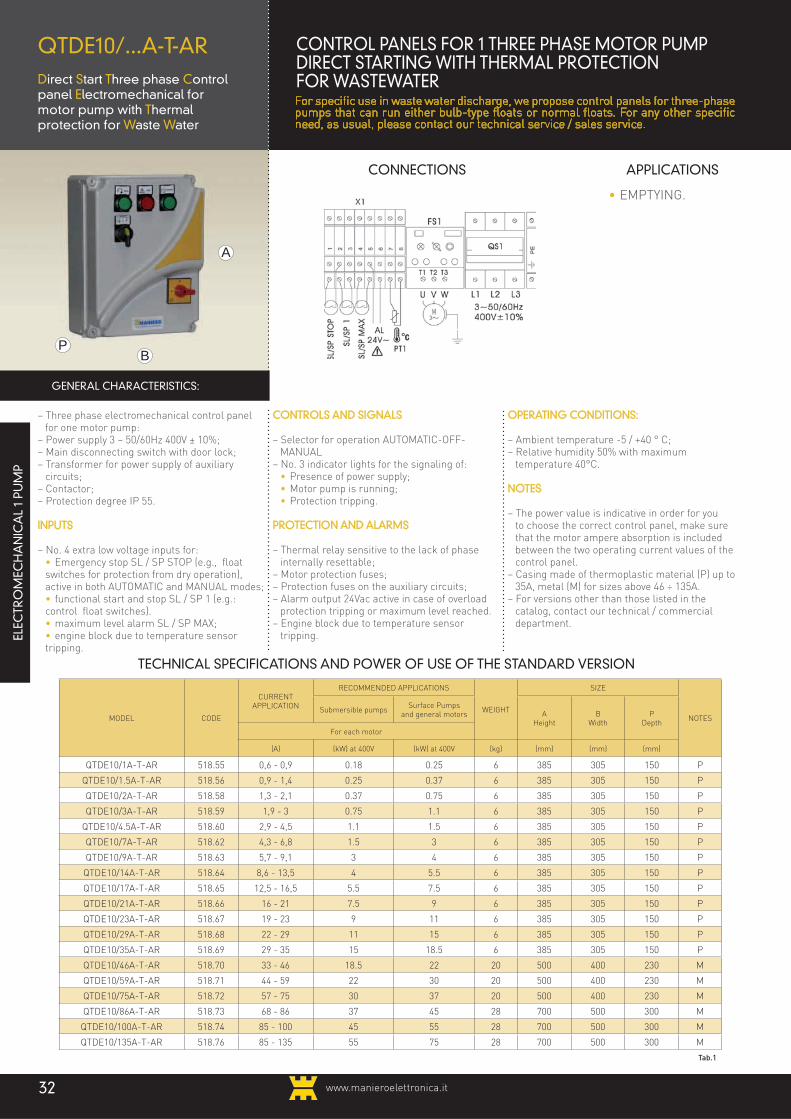
QTDE10/...A-T-ARDirect Start Three phase Control panel Electromechanical formotor pump with Thermalprotection for Waste Water
– Three phase electromechanical control panel for one motor pump:
– Power supply 3 ~ 50/60Hz 400V ± 10%;– Main disconnecting switch with door lock;– Transformer for power supply of auxiliary
circuits;– Contactor;– Protection degree IP 55.
INPUTS
– No. 4 extra low voltage inputs for: • Emergency stop SL / SP STOP (e.g., float
switches for protection from dry operation), active in both AUTOMATIC and MANUAL modes;
• functional start and stop SL / SP 1 (e.g.: control float switches).
• maximum level alarm SL / SP MAX; • engine block due to temperature sensor
tripping.
CONTROLS AND SIGNALS
– Selector for operation AUTOMATIC-OFF-MANUAL
– No. 3 indicator lights for the signaling of: • Presence of power supply; • Motor pump is running; • Protection tripping.
PROTECTION AND ALARMS
– Thermal relay sensitive to the lack of phase internally resettable;
– Motor protection fuses;– Protection fuses on the auxiliary circuits;– Alarm output 24Vac active in case of overload
protection tripping or maximum level reached.– Engine block due to temperature sensor
tripping.
OPERATING CONDITIONS:
– Ambient temperature -5 / +40 ° C;– Relative humidity 50% with maximum
temperature 40°C.
NOTES
– The power value is indicative in order for you to choose the correct control panel, make sure that the motor ampere absorption is included between the two operating current values of the control panel.
– Casing made of thermoplastic material (P) up to 35A, metal (M) for sizes above 46 ÷ 135A.
– For versions other than those listed in the catalog, contact our technical / commercial department.
• EMPTYING.
GENERAL CHARACTERISTICS:
TECHNICAL SPECIFICATIONS AND POWER OF USE OF THE STANDARD VERSION
MODEL CODE
CURRENTAPPLICATION
RECOMMENDED APPLICATIONS
WEIGHT
SIZE
NOTESSubmersible pumps
Surface Pumpsand general motors A
HeightB
WidthP
DepthFor each motor
(A) (kW) at 400V (kW) at 400V (kg) (mm) (mm) (mm)
QTDE10/1A-T-AR 518.55 0,6 - 0,9 0.18 0.25 6 385 305 150 P
QTDE10/1.5A-T-AR 518.56 0,9 - 1,4 0.25 0.37 6 385 305 150 P
QTDE10/2A-T-AR 518.58 1,3 - 2,1 0.37 0.75 6 385 305 150 P
QTDE10/3A-T-AR 518.59 1,9 - 3 0.75 1.1 6 385 305 150 P
QTDE10/4.5A-T-AR 518.60 2,9 - 4,5 1.1 1.5 6 385 305 150 P
QTDE10/7A-T-AR 518.62 4,3 - 6,8 1.5 3 6 385 305 150 P
QTDE10/9A-T-AR 518.63 5,7 - 9,1 3 4 6 385 305 150 P
QTDE10/14A-T-AR 518.64 8,6 - 13,5 4 5.5 6 385 305 150 P
QTDE10/17A-T-AR 518.65 12,5 - 16,5 5.5 7.5 6 385 305 150 P
QTDE10/21A-T-AR 518.66 16 - 21 7.5 9 6 385 305 150 P
QTDE10/23A-T-AR 518.67 19 - 23 9 11 6 385 305 150 P
QTDE10/29A-T-AR 518.68 22 - 29 11 15 6 385 305 150 P
QTDE10/35A-T-AR 518.69 29 - 35 15 18.5 6 385 305 150 P
QTDE10/46A-T-AR 518.70 33 - 46 18.5 22 20 500 400 230 M
QTDE10/59A-T-AR 518.71 44 - 59 22 30 20 500 400 230 M
QTDE10/75A-T-AR 518.72 57 - 75 30 37 20 500 400 230 M
QTDE10/86A-T-AR 518.73 68 - 86 37 45 28 700 500 300 M
QTDE10/100A-T-AR 518.74 85 - 100 45 55 28 700 500 300 M
QTDE10/135A-T-AR 518.76 85 - 135 55 75 28 700 500 300 M
Tab.1
ELEC
TRO
MEC
HA
NIC
AL
1 PU
MP
CONTROL PANELS FOR 1 THREE PHASE MOTOR PUMPDIRECT STARTING WITH THERMAL PROTECTIONFOR WASTEWATERFor specific use in waste water discharge, we propose control panels for three-phase pumps that can run either bulb-type floats or normal floats. For any other specific need, as usual, please contact our technical service / sales service.

www.manieroelettronica.it 33
WARNINGThe following table (Table 3) shows the models for which there will be definitely a casing larger than the standard model shown in Table 1.
VERSIONS
The control panels also have versions with features that differ from the standard, their code varies in order to distinguish the versions as shown in Table 2. When ordering you must locate the code of the desired product, adding to the "standard code" the suffix "release code" as shown in Table 2 (e.g. 518.67.10). It follows that the model is formed by the "standard" part having as a suffix the part "version" (Ex. QTDE10/23A-T-AR+DS).
OPTIONAL FEATURES
– Probe device water infiltration, probe device for the control of water infiltration on motor oil chamber complete with indicator light.
Codestandard
Codeversion
Modelstandard
Modelversion
518.nn .10 QMDE10/...A-T-AR +DS
OPTIONAL FEATURESVERSION CODE
10
Probe device water infiltration •
Tab.2
MODELCODE
STANDARD
VERSION CODE
10
QTDE10/1A-T-AR 518.55
QTDE10/1.5A-T-AR 518.56
QTDE10/2A-T-AR 518.58
QTDE10/3A-T-AR 518.59
QTDE10/4.5A-T-AR 518.60
QTDE10/7A-T-AR 518.62
QTDE10/9A-T-AR 518.63
QTDE10/14A-T-AR 518.64
QTDE10/17A-T-AR 518.65
QTDE10/21A-T-AR 518.66
QTDE10/23A-T-AR 518.67
QTDE10/29A-T-AR 518.68
QTDE10/35A-T-AR 518.69
QTDE10/46A-T-AR 518.70
QTDE10/59A-T-AR 518.71
QTDE10/75A-T-AR 518.72
QTDE10/86A-T-AR 518.73
QTDE10/100A-T-AR 518.74
QTDE10/135A-T-AR 518.76
Tab.3

www.manieroelettronica.it34
A
BP
CONNECTIONS APPLICATIONS
QTSE10/...A-TElectromechanical ThreephaseStar Delta Start control panelfor one motor pumpwith thermal protection
– Three phase electromechanical control panel for motor pump (or generic motor);
– Power supply 3 ~ 50/60Hz 400V ± 10%;– Main disconnecting switch with door lock;– Transformer for power supply of auxiliary circuits;– Contactors;– Timer changeover Star Delta adjustable (0,1 ÷
600s);– Protection degree IP55 (IP54 for version "40").
INPUTS
– No. 2 extra low voltage inputs for: • Emergency stop SL / SP STOP (e.g., float
switches for protection from dry operation), active in both AUTOMATIC and MANUAL modes;
• functional start and stop SL / SP 1 (e.g..: control float switches).
NOTE SL/SP1 and SL / SP STOP may be float switches pressure switches.
CONTROLS AND SIGNALS
– Selector switch for OFF-AUTOMATIC-MANUAL operation;
– Auto retaining; operation in emptying or filling with two floats one for start and one for stop selectable via special rotary switch;
– No. 3 indicator lights for the signaling of: • Presence of power supply; • Motor pump (or motor) is running; • Protection tripping.
PROTECTION AND ALARMS
– Thermal relay sensitive to the lack of phase inter-nally resettable;
– Motor protection fuses;– Protection fuses on the auxiliary circuits.
OPERATING CONDITIONS:
– Ambient temperature -5 / +40 ° C;– Relative humidity 50% with maximum temperature
40°C.
NOTES
– The power value is indicative in order for you to choose the correct control panel, make sure that the motor ampere absorption is included between the two operating current values of the control panel.
– Casing made of thermoplastic material (P) up to 28A, metal (M) for sizes above 36 ÷ 860A.
– For versions other than those listed in the catalog, contact our technical / commercial department.
• EMPTYING;
• FILLING;
• PRESSURIZATION.
GENERAL CHARACTERISTICS:
TECHNICAL SPECIFICATIONS AND POWER OF USE OF THE STANDARD VERSION
MODEL CODE
CURRENTAPPLICATION
RECOMMENDED APPLICATIONS
WEIGHT
SIZE
NOTESSubmersible pumpsSurface Pumps
and general motorsA
HeightB
WidthP
Depth
(A) (kW) at 400V (kW) at 400V (kg) (mm) (mm) (mm)
QTSE10/8A-T 512.12 4,9 - 7,8 2.2 3 5 385 305 160 P
QTSE10/12A-T 512.13 7,5 - 12 3 4 5 385 305 160 P
QTSE10/16A-T 512.15 10 - 16 5.5 7.5 5 385 305 160 P
QTSE10/23A-T 512.16 15 - 23 7.5 9 6 385 305 160 P
QTSE10/28A-T 512.17 21 - 28 9 11 6 385 305 160 P
QTSE10/36A-T 512.18 27 - 36 11 15 16.5 500 400 230 M
QTSE10/39A-T 512.19 33 - 39 15 18.5 16.5 500 400 230 M
QTSE10/50A-T 512.20 38 - 50 18.5 22 16.5 500 400 230 M
QTSE10/60A-T 512.21 50 - 60 22 30 16.5 500 400 250 M
QTSE10/78A-T 512.22 57 - 78 30 37 30 700 500 250 M
QTSE10/100A-T 512.24 75 - 100 45 55 30 700 500 250 M
QTSE10/130A-T 512.25 98 - 130 55 70 30 700 500 250 M
QTSE10/195A-T 512.28 120 - 195 90 110 M
QTSE10/235A-T 512.29 150- 235 110 132 M
QTSE10/310A-T 512.30 200 - 310 132 160 M
QTSE10/390A-T 512.31 245 - 390 160 200 M
QTSE10/470A-T 512.32 300 - 470 200 250 M
QTSE10/650A-T 512.34 410 - 650 250 355 M
QTSE10/860A-T 512.35 520 - 860 355 400 M
Tab.1
QS1
L1 L2 L33~50/60Hz 400V±10%
PE
SL/S
P ST
OP
SL/S
P 1
1 2 3
X2
W2
U2
V2
U1
V1
W1
X1
ELEC
TRO
MEC
HA
NIC
AL
1 PU
MP
CONTROL PANELS FOR 1 THREE PHASE MOTOR PUMPSTAR DELTA START WITH THERMAL PROTECTION
The control panels for pumps with Star Delta Star are used to limit the inrush current during motor Starting up to 30% compared to that achieved by a direct starting, which is useful in cases where there are requirements that restrict the use of direct Starting.

www.manieroelettronica.it 35
WARNINGThe following table (Table 3) shows the models for which there will be definitely a casing larger than the standard model shown in Table 1.
VERSIONS
The control panels also have versions with features that differ from the standard, their code varies in order to distinguish the versions as shown in Table 2. When ordering you must locate the code of the desired product, adding to the "standard code" the suffix "release code" as shown in Table 2 (e.g. 512.18.40). It follows that the model is formed by the "standard" part having as a suffix the part "version" (Ex. QTSE10/36A-T-40).
OPTIONAL FEATURES
– Level control module, electronic module for level control with 3 probes (probes not included).
– NO Alarm + 24Vac output; the output is acti-vated if the protection against overload is trig-gered (alarm and output appropriately wired may activate a flashing light or other compo-nent with 24Vac / 0.2 A – 5VA power supply).
– Hour meter; displays the hours of motor operation.
– Voltmeter + Volt. Switch + Ammeter; voltme-ter + voltmeter switch + Ammeter with current transformer (TA) only if necessary.
– Phase control module; stops operation in case of phase loss imbalance of supply voltage.
– Start and stop push button; stop and start con-trols on the front panel are activated only with the operating selector in the MANUAL position.
– Multifunction digital instrument; instrument with digital display for visualization and control of voltage, current (display of a single phase with only one TA), power and frequency. It also serves as phase control module.
– Timer; electronic timer multi-function and multi-voltage (set to delay starting in case of sudden return of the power supply).
Codestandard
Codeversion
Modelstandard
Modelversion
512.nn .xx QTSE10/...A-T -xx
OPTIONAL FEATURESVERSION CODE
10 20 30 40
Probe level control module • • • •
Voltmeter + Volt. Switch + Ammeter • •
Alarm NO + output 24Vac • •
Hour meter • •
Phase control module •
Start/stop button •
Multifunction digital device •
Timer (delay return to the network) •
Tab.2
MODELCODE
STANDARD
VERSION CODE
10 20 30 40
QTSE10/8A-T 512.12 • • •
QTSE10/12A-T 512.13 • • •
QTSE10/16A-T 512.15 • • •
QTSE10/23A-T 512.16 • • •
QTSE10/28A-T 512.17 • • •
QTSE10/36A-T 512.18
QTSE10/39A-T 512.19
QTSE10/50A-T 512.20
QTSE10/60A-T 512.21
QTSE10/78A-T 512.22
QTSE10/100A-T 512.24
QTSE10/130A-T 512.25
QTSE10/195A-T 512.28
QTSE10/235A-T 512.29
QTSE10/310A-T 512.30
QTSE10/390A-T 512.31
QTSE10/470A-T 512.32
QTSE10/650A-T 512.34
QTSE10/860A-T 512.35
Tab.3
e.g.: QTSE10/60A-T-30.

www.manieroelettronica.it36
A
BP
CONNECTIONS APPLICATIONS
QTSE10/...A-T-ARElectromechanical Threephase Star Delta Start control panel for onemotor pump with Thermalprotection for Waste Water
– Three phase electromechanical control panel for one motor pump:
– Power supply 3 ~ 50/60Hz 400V ± 10%;– Main disconnecting switch with door lock;– Transformer for power supply of auxiliary circuits;– Contactors;– Timer changeover Wye-Delta adjustable (0,1 ÷
600s);– Degree of protection IP 55.
INPUTS
– No. 4 extra low voltage inputs for: • Emergency stop SL / SP STOP (e.g., float
switches for protection from dry operation), active in both AUTOMATIC and MANUAL modes;
• functional start and stop SL / SP 1 (e.g.: control float switches).
• Maximum level alarm • engine block due to temperature sensor tripping.
CONTROLS AND SIGNALS
– Selector switch for OFF-AUTOMATIC-MANUAL operation;
– No. 3 indicator lights for the signaling of: • Presence of power supply; • Motor pump is running; • Protection tripping.
PROTECTION AND ALARMS
– Thermal relay sensitive to the lack of phase inter-nally resettable;
– Motor protection fuses;– Protection fuses on the auxiliary circuits;– Alarm output 24Vac active in case of overload pro-
tection tripping for maximum level reached.– Engine block due to temperature sensor tripping.
OPERATING CONDITIONS:
– Ambient temperature -5 / +40 ° C;– Relative humidity 50% with maximum temperature
40°C.
NOTES
– The power value is indicative in order for you to choose the correct control panel, make sure that the motor ampere absorption is included between the two operating current values of the control panel.
– Casing made of thermoplastic material (P) up to 28A, metal (M) for sizes above 36 ÷ 860A.
– For versions other than those listed in the catalog, contact our technical / commercial department.
• EMPTYING.
GENERAL CHARACTERISTICS:
TECHNICAL SPECIFICATIONS AND POWER OF USE OF THE STANDARD VERSION
MODEL CODE
CURRENTAPPLICATION
RECOMMENDED APPLICATIONS
WEIGHT
SIZE
NOTESSubmersible pumpsSurface Pumps
and general motorsA
HeightB
WidthP
Depth
(A) (kW) at 400V (kW) at 400V (kg) (mm) (mm) (mm)
QTSE10/8A-T-AR 514.12 4,9 - 7,8 2.2 3 6 460 380 160 P
QTSE10/12A-T-AR 514.13 7,5 - 12 3 4 6 460 380 160 P
QTSE10/16A-T-AR 514.15 10 - 16 5.5 7.5 6 460 380 160 P
QTSE10/23A-T-AR 514.16 15 - 23 7.5 9 6 460 380 160 P
QTSE10/28A-T-AR 514.17 21 - 28 9 11 6 460 380 160 P
QTSE10/36A-T-AR 514.18 27 - 36 11 15 17 500 400 230 M
QTSE10/39A-T-AR 514.19 33 - 39 15 18.5 17 500 400 230 M
QTSE10/50A-T-AR 514.20 38 - 50 18.5 22 17 500 400 230 M
QTSE10/60A-T-AR 514.21 50 - 60 22 30 17 500 400 250 M
QTSE10/78A-T-AR 514.22 57 - 78 30 37 30.5 700 500 250 M
QTSE10/100A-T-AR 514.24 75 - 100 45 55 30.5 700 500 250 M
QTSE10/130A-T-AR 514.25 98 - 130 55 70 30.5 700 500 250 M
QTSE10/195A-T-AR 514.28 120 - 195 90 110 M
QTSE10/235A-T-AR 514.29 150- 235 110 132 M
QTSE10/310A-T-AR 514.30 200 - 310 132 160 M
QTSE10/390A-T-AR 514.31 245 - 390 160 200 M
QTSE10/470A-T-AR 514.32 300 - 470 200 250 M
QTSE10/650A-T-AR 514.34 410 - 650 250 355 M
QTSE10/860A-T-AR 514.35 520 - 860 355 400 M
Tab.1
ELEC
TRO
MEC
HA
NIC
AL
1 PU
MP
CONTROL PANELS FOR 1 THREE PHASE MOTOR PUMP START DELTA START WITH THERMAL PROTECTIONThe control panels for pumps with Star Delta Start are used to limit the inrush current during motor Starting up to 30% compared to that achieved by a direct starting, which is useful in cases where there are requirements that restrict the use of direct Starting. For specific use in waste water discharge, we propose control panels for three-phase pumps that can run either bulb-type floats or normal floats.

www.manieroelettronica.it 37
WARNINGThe following table (Table 3) shows the models for which there will be definitely a casing larger than the standard model shown in Table 1.
VERSIONS
The control panels also have versions with features that differ from the standard, their code varies in order to distinguish the versions as shown in Table 2. When ordering you must locate the code of the desired product, adding to the "standard code" the suffix "release code" as shown in Table 2 (e.g. 514.18.10). It follows that the model is formed by the "standard" part having as a suffix the part "version" (Ex. QTSE10/36A-T-AR+DS).
OPTIONAL FEATURES
– Probe device water infiltration, probe device for the control of water infiltration on motor oil chamber complete with indicator light.
Codestandard
Codeversion
Modelstandard
Modelversion
514.nn .10 QMDE10/...A-T-AR +DS
OPTIONAL FEATURESVERSION CODE
10
Probe device water infiltration
Tab.2
MODELCODE
STANDARD
VERSION CODE
10
QTSE10/8A-T-AR 514.12
QTSE10/12A-T-AR 514.13
QTSE10/16A-T-AR 514.15
QTSE10/23A-T-AR 514.16
QTSE10/28A-T-AR 514.17
QTSE10/36A-T-AR 514.18
QTSE10/39A-T-AR 514.19
QTSE10/50A-T-AR 514.20
QTSE10/60A-T-AR 514.21
QTSE10/78A-T-AR 514.22
QTSE10/100A-T-AR 514.24
QTSE10/130A-T-AR 514.25
QTSE10/195A-T-AR 514.28
QTSE10/235A-T-AR 514.29
QTSE10/310A-T-AR 514.30
QTSE10/390A-T-AR 514.31
QTSE10/470A-T-AR 514.32
QTSE10/650A-T-AR 514.34
QTSE10/860A-T-AR 514.35
Tab.3

www.manieroelettronica.it38
A
BP
CONNECTIONS APPLICATIONS
QTRE10/...A-TThree phase Reactance Control panel Electromechanical for 1motor pump withThermal protection
– Three phase electromechanical control panel for motor pump (or generic motor);
– Power supply 3 ~ 50/60Hz 400V ± 10%;– Main disconnecting switch with door lock;– Transformer for power supply of auxiliary
circuits;– Contactors;– Adjustable Timer for Starting (0.1 ÷ 600s);– Protection degree IP55 (IP54 for version "40").
INPUTS
– No. 2 extra low voltage inputs for: • Emergency stop SL / SP STOP (e.g., float
switches for protection from dry operation), ac-tive in both AUTOMATIC and MANUAL modes;
• functional start and stop SL / SP 1 (e.g.: con-trol float switches).
NOTE SL/SP1 and SL / SP STOP may be float switches or pressure switches.
CONTROLS AND SIGNALS
– Selector switch for OFF-AUTOMATIC-MANUAL operation;
– No. 3 indicator lights for the signaling of: • Presence of power supply; • Motor pump (or motor) is running; • Protection tripping.
PROTECTION AND ALARMS
– 2 thermal relays sensitive to the absence of phase internally resettable (FS1 = prot. motor speed, FS2 = prot. motor in Starting);
– Motor protection fuses;– Protection fuses on the auxiliary circuits.
OPERATING CONDITIONS:– Ramp-up time 15 seconds, max.;– Frequency of operations / hour: max. 4 of which
no more than 2 consecutive;– The setting of the timer function must be done
in function of the motor pump 0-15 sec.)– Ambient temperature -5 / +40 ° C;– Relative humidity 50% with maximum tempera-
ture 40°C.
NOTES
– The power value is indicative in order for you to choose the correct control panel, make sure that the motor ampere absorption is included between the two operating current values of the control panel.
– Housing made of metal (M) for all sizes.– For versions other than those listed in the
catalog, contact our technical / commercial department.
• FILLING;
• PRESSURIZATION.
GENERAL CHARACTERISTICS:
TECHNICAL SPECIFICATIONS AND POWER OF USE OF THE STANDARD VERSION
MODEL CODE
CURRENTAPPLICATION
RECOMMENDED APPLICATIONS
WEIGHT
SIZE
NOTESSubmersible pumpsSurface Pumps
and general motorsA
HeightB
WidthP
Depth
(A) (kW) at 400V (kW) at 400V (kg) (mm) (mm) (mm)
QTRE10/9A-T 511.63 5,7 - 9,1 3 4 24.5 500 400 280 M
QTRE10/14A-T 511.64 8,5 - 13,5 4 5.5 24.5 500 400 280 M
QTRE10/17A-T 511.65 12,5 - 16,5 5.5 7.5 24.5 500 400 280 M
QTRE10/21A-T 511.66 16 - 21 7.5 9 24.5 500 400 280 M
QTRE10/23A-T 511.67 19 - 23 9 11 24.5 500 400 280 M
QTRE10/29A-T 511.68 23 - 29 11 15 38.5 700 500 280 M
QTRE10/35A-T 511.69 29 - 35 15 18.5 38.5 700 500 280 M
QTRE10/46A-T 511.70 33 - 46 18.5 22 63 800 600 330 M
QTRE10/59A-T 511.71 44 - 59 22 30 63 800 600 330 M
QTRE10/75A-T 511.72 57 - 75 30 37 63 800 600 330 M
QTRE10/86A-T 511.73 66 - 86 37 45 63 800 600 350 M
QTRE10/100A-T 511.74 85 - 100 45 55 M
QTRE10/135A-T 511.76 85 - 135 55 75 M
QTRE10/180A-T 511.77 115 - 180 75 90 M
QTRE10/230A-T 511.78 140 - 230 90 110 M
QTRE10/270A-T 511.79 170 - 270 110 132 M
QTRE10/380A-T 511.81 240 - 380 132 200 M
QTRE10/450A-T 511.82 290 - 450 200 250 M
Tab.1
ELEC
TRO
MEC
HA
NIC
AL
1 PU
MP
CONTROL PANELS FOR 1 THREE PHASE MOTOR PUMP REACTANCE STARTING WITH THERMAL PROTECTIONThe control panels for pumps with Reactance Starting are used to limit the inrush current during motor Starting up to 30% compared to that achieved by a direct starting, which is useful in cases where there are requirements that restrict the use of direct Starting.

www.manieroelettronica.it 39
OPTIONAL FEATURESVERSION CODE
10 20 30 40
Probe level control module • • • •
Voltmeter + Volt. Switch + Ammeter • •
Alarm NO + output 24Vac • •
Hour meter • •
Phase control module •
Start/stop button •
Multifunction digital device •
Timer (delay return to the network) •
Tab.2
WARNINGThe following table (Table 3) shows the models for which there will be definitely a casing larger than the standard model shown in Table 1.
VERSIONS
The control panels also have versions with features that differ from the standard, their code varies in order to distinguish the versions as shown in Table 2. When ordering you must locate the code of the desired product, adding to the "standard code" the suffix "release code" as shown in Table 2 (e.g. 511.69.20). It follows that the model is formed by the "standard" part having as a suffix the part "version" (Ex. QTRE10/35A-T-20).
e.g.: QTRE10/23A-T-20.
OPTIONAL FEATURES
– Level control module, electronic module for level control with 3 probes (probes not included).
– NO Alarm + 24Vac output; the output is acti-vated if the protection against overload is trig-gered (alarm and output appropriately wired may activate a flashing light or other compo-nent with 24Vac / 0.2 A – 5VA power supply).
– Hour meter, displays hours of motor opera-tion.
– Voltmeter + Volt. Switch + Ammeter; voltme-ter + voltmeter switch + Ammeter with current transformer (TA) only if necessary.
– Phase control module; stops operation in case of phase loss imbalance of supply voltage.
– Start and stop push button; stop and start con-trols on the front panel are activated only with the operating selector in the MANUAL position.
– Multifunction digital instrument; instrument with digital display for visualization and control of voltage, current (display of a single phase with only one TA), power and frequency. It also serves as phase control module.
– Timer; electronic timer multi-function and multi-voltage (set to delay Starting in case of sudden return of the power supply).
Codestandard
Codeversion
Modelstandard
Modelversion
511.nn .xx QTSE10/...A-T -xx
MODELCODE
STANDARD
VERSION CODE
10 20 30 40
QTRE10/9A-T 511.63 • • • •
QTRE10/14A-T 511.64 • • • •
QTRE10/17A-T 511.65 • • • •
QTRE10/21A-T 511.66 • • • •
QTRE10/23A-T 511.67 • • • •
QTRE10/29A-T 511.68
QTRE10/35A-T 511.69
QTRE10/46A-T 511.70
QTRE10/59A-T 511.71
QTRE10/75A-T 511.72
QTRE10/86A-T 511.73
QTRE10/100A-T 511.74
QTRE10/135A-T 511.76
QTRE10/180A-T 511.77
QTRE10/230A-T 511.78
QTRE10/270A-T 511.79
QTRE10/380A-T 511.81
QTRE10/450A-T 511.82
Tab.3

www.manieroelettronica.it40
QTSS10/...A-TThreephase Soft Start control Panel for 1 motor pump with Thermal protection
CONTROL PANELS FOR 1 THREE PHASE MOTOR PUMPSOFT-START WITH THERMAL PROTECTIONThe soft-start control panels allow the electronic Starting/slowing down via static converters and are suitable for the Starting of motor pumps for which it is necessary to avoid abrupt acceleration and / or deceleration. The acceleration and deceleration times can be adjusted independently to suit your needs and at the end of the Starting phase the motor is connected to the line.
TECHNICAL SPECIFICATIONS AND POWER OF USE
MODEL CODEPOWER
INDICATIVE AT 400V kW
POWER INDICATIVE AT
400V Hp
OPERATING CURRENT
(A) MIN
OPERATING CURRENT (A)
MAXWEIGHT KG
DIMENSIONS mm
A
DIMENSIONS mm
B
DIMENSIONS mm
P
QTSS10/7A-T 517.62 2.2 3 4.3 6.8 500 400 230
QTSS10/9A-T 517.63 3 4 5.7 9.1 500 400 230
QTSS10/14A-T 517.64 4 5.5 8.5 13.5 500 400 230
QTSS10/17A-T 517.65 5.5 7.5 12.5 16.5 500 400 230
QTSS10/21A-T 517.66 7.5 9 16 21 500 400 230
QTSS10/23A-T 517.67 9 11 19 23 500 400 230
QTSS10/29A-T 517.68 11 15 29 34 500 500 235
QTSS10/34A-T 517.69 15 18.5 29 34 500 500 235
QTSS10/46A-T 517.70 18.5 22 33 46 500 500 235
QTSS10/59A-T 517.71 22 30 44 59 500 500 235
QTSS10/75A-T 517.72 30 37 57 75 700 500 235
QTSS10/85A-T 517.73 37 45 67 85 700 500 235
QTSS10/100A-T 517.74 45 55 85 100 700 500 235
QTSS10/135A-T 517.76 55 75 85 135 1000 800 340
QTSS10/170A-T 517.77 75 90 115 170 1000 800 340
QTSS10/200A-T 517.78 90 110 140 200 1000 800 340
A
BP
ELEC
TRO
MEC
HA
NIC
AL
1 PU
MP
X2
SL/S
P S
TOP
SL/S
P 1
1 2 3
QS1
L1 L2 L33~50/60Hz 400V±10%
PE
U V W
X1
PE
CONNECTIONS
APPLICATIONS
• EMPTYING
• FILLING;
• PRESSURIZATION.
- Three phase electromechanical control panel for motor pump (or generic motor);
- Power supply 3 ~ 50/60Hz 400V ± 10%;- Main disconnecting switch with door lock;- Transformer for power supply of auxiliary circuits;- Soft-starter with internal bypass- Contactors;- Regulators: a) starting torque; b) acceleration time; c) deceleration time;- Protection degree IP 55.
INPUTS
- No. 2 extra low voltage inputs for: • Emergency stop SL / SP STOP (e.g., float
switches for protection from dry operation), active in both AUTOMATIC and MANUAL modes;
• functional start and stop SL / SP 1 (e.g..: control float switches).
NOTE SL/SP1 and SL / SP STOP may be float switches or pressure switches.
CONTROLS AND SIGNALS
- Selector switch for OFF-AUTOMATIC-MANUAL operation;
- Auto retaining; operation in emptying or filling with two floats one for start and one for stop selectable via special rotary switch;
- No. 3 indicator lights for the signaling of: • Presence of power supply; • Motor pump (or motor) is running; • Protection tripping.
PROTECTION AND ALARMS
- Thermal relay sensitive to the lack of phase internally resettable;
- Motor protection fuses;- Protection fuses on the auxiliary circuits.
OPERATING CONDITIONS:
- Ambient temperature -5 / +40 ° C;- Relative humidity 50% with maximum temperature
40°C.
NOTES
- The power value is indicative in order for you to choose the correct control panel, make sure that the motor ampere absorption is included between the two operating current values of the control panel.
- Housing made of metal (M) for all sizes.- For versions other than those listed in the catalog,
contact our technical / commercial department.
GENERAL CHARACTERISTICS:

www.manieroelettronica.it 41
OPTIONAL FEATURESVERSION CODE
10 20
Probe level control module • •
Voltmeter + Volt. Switch + Ammeter •
Tab.2
WARNINGThe following table (Table 3) shows the models for which there will be definitely a casing larger than the standard model shown in Table 1.
VERSIONS
The control panels also have versions with features that differ from the standard, their code varies in order to distinguish the versions as shown in Table 2. When ordering you must locate the code of the desired product, adding to the "standard code" the suffix "release code" as shown in Table 2 (e.g. 517.67.20). It follows that the model is formed by the "standard" part having as a suffix the part "version" (Ex. QTSS10/23A-T-20).
e.g.: QTSS10/23A-T-20.
OPTIONAL FEATURES
- Level control module, electronic module for level control with 3 probes (probes not included).
- Voltmeter + Volt. Switch + Ammeter; voltmeter + voltmeter switch + Ammeter with current trans-former (TA) only if necessary.
Codestandard
Codeversion
Modelstandard
Modelversion
517.nn .xx QTSS10/...A-T -xx
MODELCODE
STANDARD
VERSION CODE
10 20
QTSS10/7A-T 517.62
QTSS10/9A-T 517.63
QTSS10/14A-T 517.64
QTSS10/17A-T 517.65
QTSS10/21A-T 517.66
QTSS10/23A-T 517.67
QTSS10/29A-T 517.68
QTSS10/34A-T 517.69
QTSS10/46A-T 517.70
QTSS10/59A-T 517.71
QTSS10/75A-T 517.72
QTSS10/85A-T 517.73
QTSS10/100A-T 517.74
QTSS10/135A-T 517.76
QTSS10/170A-T 517.77
QTSS10/200A-T 517.78
Tab.3

A
BP
CONNECTIONS APPLICATIONS
QTIF10/...A-A Three phase Control panel with Frequency Inverterfor motor pumps
- Three phase control panel for motor pump with frequency inverter for the pressurization in wa-ter systems and for water treatment in general;
- Power supply 3 ~ 50/60Hz 400V ± 10%;- RFI Noise Filter (for civil);- Main disconnecting switch with door lock;- Forced ventilation;- Protection degree IP 54.
CONTROL INPUT AND OUTPUT
- Maximum motor cable length: 30m with shielded cable, 40m with unshielded cable;
CONTROL INPUT AND OUTPUT
- Extra low voltage input to analog pressure transmitter 2 / 3 wire 4 ... 20mA (e.g. SPE3/...BG ¼ M-5m), power output 24V;
- No. 3 extra low voltage inputs for: • Emergency stop (e.g maximum pressure
switch) • functional stop (e.g minimum level float); • external control start / stop with a fixed speed
inverter (e.g: adjustment pressure switch).- Relay output with changeover contact for alarm
(250V ~ 5Amax resistive charge).
CONTROLS AND SIGNALS
- External panel with multi-language keyboard and graphic display for:
• Display of the status of the inverter, alerts and alarms;
• Display and setting of operating parameters;- Selector for the system with operation in
"Automatic-Off-Manual";
SETTABLE PARAMETERS
- Typical parameters for AUTOMATIC operation (constant pressure):
• Nominal pressure of the system; • Pressure sensor capacity; • Minimum and maximum frequency of motor
operation; • Enabling arrest for zero flow (shutting-off of
delivery); • Pressure to restart when flow is reestablished
(reopening of delivery);- Typical parameters for MANUAL operation
(constant speed): • Output frequency (generated by the inverter to
power the motor pump).
PROTECTION AND ALARMS
- Lack of or faulty pressure sensor;- Electronic overload protection with automatic
limitation of the output frequency of arrest;- Electronic protection for over temperature of
the motor pump without the use of PTC sensors applied to the motor;
- Electronic protection for overheating of the inverter;
- Fuses for the protection of the inverter power supply line.
OPERATING CONDITIONS:
- Ambient temperature -5 / +40 ° C;- Maximum relative humidity 50% with maximum
temperature 40°C.
NOTES
- The power value is indicative, in order to choose a correct control panel verify the absorption amps of the motor.
- Housing made of metal (M) for all sizes.- For versions other than those listed in the
catalog, contact our technical / commercial department.
• PRESSURIZATION.
GENERAL CHARACTERISTICS:
MODEL CODE
CURRENTAPPLICATION
RECOMMENDED APPLICATIONS
WEIGHT
SIZE
NOTESSubmersible pumpsSurface Pumps
and general motorsA
HeightB
WidthP
Depth
(A) (kW) at 400V (kW) at 400V (kg) (mm) (mm) (mm)
QTIF10/3.3A-A 531.09 3.3 0.75 1.1 18 500 400 290 M
QTIF10/4.1A-A 531.10 4.1 1.1 1.5 18 500 400 290 M
QTIF10/5.6A-A 531.11 5.6 1.5 2.2 20 500 400 290 M
QTIF10/7.3A-A 531.12 7.3 2.2 3 20 500 400 290 M
QTIF10/8.8A-A 531.13 8.8 3 4 20 500 400 290 M
QTIF10/12A-A 531.14 12.5 4 5.5 20 500 400 290 M
QTIF10/15A-A 531.15 15.6 5.5 7.5 20 500 400 290 M
QTIF10/23A-A 531.17 23.1 7.5 11 34 800 600 340 M
QTIF10/31A-A 531.18 31 11 15 34 800 600 340 M
QTIF10/38A-A 531.19 38 15 18.5 34 800 600 340 M
QTIF10/44A-A 531.20 44 18.5 22 34 800 600 340 M
1 EL
ECTR
ON
IC P
UM
P
ACCESSORIES
Pressure sensor SPE3
850.965 (10bar)
850.966 (25bar)
www.manieroelettronica.it42

A
BP
QCS/...F-0,37kW-MTGreenhouse Climate control Con-trol panel Windows 0,37kWwith Thermal Protection
- Power supply 3 ~ 50/60Hz 400V ± 10%;- Main disconnecting switch with door lock;- Transformer for power supply of auxiliary cir-
cuits;- Timers for handling of windows in sequence;- Contactor for operation of each window;- Protection degree IP 55.
INPUTS AND OUTPUTS
- No. 5 extra low voltage inputs for: • temperature probe (probe included); • light probe (probe included); • humidity probe; • anemometer; • rain sensor.
CONTROLS AND SIGNALS
- Control stop output Common / Open / Close (for each window):
- Selector switch for OFF-AUTOMATIC-MANUAL operation;
- Switches excluding window operation (one for each window);
- Switch Open / Stop / Close;- Operation button (for each window);- Indicator lights for the signaling of: • Presence of power supply; • Moving window (one for each window); • Protection tripping (cumulative).
PROTECTION AND ALARMS
- Motor protection circuit and protection of the windows with adjustable trip current (one for each window);
- Power supply protection fuses;- Protection fuses on the auxiliary circuits.
OPERATING CONDITIONS:
- Ambient temperature -5 / +40 ° C;
NOTES
- Ready for the application of: • shading function, • heating function, NOTE These functions involve the addition of
components and possible change of the box.- The probes which are not included should
be ordered separately (see section 7 ADDITIONAL EQUIPMENT).
- Housing made of fiberglass or polycarbonate.- For versions other than those listed in the
catalog, contact our technical / commercial department.
GENERAL CHARACTERISTICS:
TECHNICAL SPECIFICATIONS AND POWER OF USE OF THE STANDARD VERSION
MODELNUMBER OF
WINDOWSCODE
CURRENTAPPLICATION
INDICATIVE POWER
WEIGHT
SIZE
AHeight
BWidth
PDepth
For each motor
(A) (kW) at 400V (kg) (mm) (mm) (mm)
QCS/4F-0,37kW-MT 4 312.02 1 - 1,6 0.37 30 650 500 250
QCS/8F-0,37kW-MT 8 312.03 1 - 1,6 0.37 45 800 600 300
QCS/16F-0,37kW-MT 16 312.04 1 - 1,6 0.37 75 950 600 300
QCS/24F-0,37kW-MT 24 312.05 1 - 1,6 0.37 105 1150 800 300
GR
EENH
OU
SE CLIM
ATE C
ON
TRO
L PAN
ELS
CONTROL PANELS FOR GREENHOUSE CLIMATE CONTROL FOR MOTORS USED FOR OPENING AND CLOSING OF WINDOWS, SHADING AND HEATING The basic range is used to control 4, 8, 16 and 24 windows, the control panels are made of fiberglass or polycarbonate and are therefore suitable for installation inside the greenhouse.Since, however, there are many and different application needs and hence the different types of these control panels, our technical office is able to develop specific control panels to measure
6943www.manieroelettronica.it
Heating
Temperature
Shading
Wind Direction / Speed
Rain sensor
Opening / Closingwindows
Humidity
Brightnesssensor

www.manieroelettronica.it44
A
BP
CONNECTIONS APPLICATIONS
– Three phase electromechanical control panel for two motor pumps (or two generic motor);
– Power supply 3 ~ 50/60Hz 230V ± 10%;– Main disconnecting switch with door lock;– Transformer for power supply of auxiliary
circuits;– Contactor for each motor;– Protection degree IP 55.
INPUTS
– No. 3 extra low voltage inputs for: • Emergency stop SL / SP STOP (e.g, float
switches for protection from dry operation), active in both AUTOMATIC and MANUAL modes;
• functional start and stop SL / SP 1 and 2 (e.g.: control float switches) for each motor.
NOTE SL / SP1-2 and SL / SP STOP may be float switches or pressure switches.
CONTROLS AND SIGNALS
– Selector MANUAL-AUTOMATIC-OFF for each engine;
– Auto retaining; operation in emptying or filling with three floats two for start and one for stop selectable via special rotary switch for each motor;
– No. 5 indicator lights for the signaling of: • Presence of power supply; • Motor pump 1 or 2 (or motor 1 or 2) running; • Motor protection tripping 1 or 2.
PROTECTION AND ALARMS
– Thermal relay sensitive to the lack of phase internally resettable for each motor;
– Motor protection fuses for each motor;– Protection fuses on the auxiliary circuits.
OPERATING CONDITIONS:
– Ambient temperature -5 / +40 ° C;– Relative humidity 50% with maximum
temperature 40°C.
NOTES
– The power value is indicative in order for you to choose the correct control panel, make sure that the motor ampere absorption is included between the two operating current values of the control panel.
– Casing made of thermoplastic material (P) up to 17A;
– Prearrangement for starting capacitors.– For versions other than those listed in the
catalog, contact our technical / commercial department.
• EMPTYING;
• FILLING;
• PRESSURIZATION.
GENERAL CHARACTERISTICS:
TECHNICAL SPECIFICATIONS AND POWER OF USE OF THE STANDARD VERSION
MODEL CODE
CURRENTAPPLICATION
RECOMMENDED APPLICATIONS
WEIGHT
SIZE
NOTESSubmersible pumps
Surface Pumpsand general motors A
HeightB
WidthP
Depth
For each motor
(A) (kW) at 230V (kW) at 230V (kg) (mm) (mm) (mm)
QMDE20/2A-T 515.08 1,3 - 2,1 0.12 0.18 6.5 385 305 150 P
QMDE20/3A-T 515.09 1,9 - 3 0.18 0.25 6.5 385 305 150 P
QMDE20/4,5A-T 515.10 2,9 - 4,5 0.25 0.37 6.5 385 305 150 P
QMDE20/7A-T 515.12 4,3 - 6,8 0.55 0.75 6.5 385 305 150 P
QMDE20/9A-T 515.13 5.7 - 9.1 0.75 1.1 6.5 385 305 150 P
QMDE20/14A-T 515.14 8,6 - 13,5 1.1 1.5 9.5 460 380 150 P
QMDE20/17A-T 515.15 12,5 - 16,5 1.5 2.2 9.5 460 380 150 P
Tab.1
SL/S
P ST
OP
SL/S
P 1
1 2 3 4 5SL
/SP
2
N L
~50/60Hz 230V±10%
N L1
-QS1
C
C1
X1
N L1C
C1
X2
PE
ELEC
TRO
MEC
HA
NIC
AL
2 PU
MPS
QMDE20/...A-TSingle phase Direct StartElectromechanical control panel for 2 motor pumps with thermal protection
ELECTROMECHANICAL CONTROL PANELS FOR TWO SINGLE PHASE MOTOR PUMPS 230V WITH THERMAL PROTECTION

www.manieroelettronica.it 45
WARNINGThe following table (Table 3) shows the models for which there will be definitely a casing larger than the standard model shown in Table 1.
VERSIONS
The control panels also have versions with features that differ from the standard, their code varies in order to distinguish the versions as shown in Table 2. When ordering you must locate the code of the desired product, adding to the "standard code" the suffix "release code" as shown in Table 2 (e.g. 515.14.10). It follows that the model is formed by the "standard" part having as a suffix the part "version" (Ex. QMDE20/14A-T-10).
OPTIONAL FEATURES
– Exchanger; exchanger – electronic sequencer.
Codestandard
Codeversion
Modelstandard
Modelversion
515.nn .xx QMDE20/...A-T -xx
OPTIONAL FEATURESVERSION CODE
10
Exchanger
Tab.2
MODELCODE
STANDARD
VERSION CODE
10
QMDE20/2A-T 515.08
QMDE20/3A-T 515.09
QMDE20/4,5A-T 515.10
QMDE20/7A-T 515.12
QMDE20/9A-T 515.13
QMDE20/14A-T 515.14
QMDE20/17A-T 515.15
Tab.3

www.manieroelettronica.it46
A
BP
CONNECTIONS APPLICATIONS
– Single phase electromechanical control panel for two motor pumps:
– Power supply 3 ~ 50/60Hz 230V ± 10%;– Main disconnecting switch with door lock;– Transformer for power supply of auxiliary
circuits;– Contactor for each motor;– Exchanger;– Protection degree IP 55.
INPUTS
No. 6 extra low voltage inputs for: • Emergency stop SL / SP STOP (e.g., float
switches for protection from dry operation), active in both AUTOMATIC and MANUAL modes;
• functional start and stop SL / SP 1 (e.g.: control float switches);
• maximum level alarm SL / SP MAX; • engine block due to temperature sensor
tripping.
CONTROLS AND SIGNALS
– Selector MANUAL-AUTOMATIC-OFF for each engine;
– No. 5 indicator lights for the signaling of: • Presence of power supply; • Motor pump 1 or 2 running; • Motor protection tripping 1 or 2.
PROTECTION AND ALARMS
– Thermal relay sensitive to the lack of phase internally resettable for each motor;
– Motor protection fuses for each motor;– Protection fuses on the auxiliary circuits.– Alarm output 24Vac active in case of overload
protection tripping or maximum level reached.– Engine block due to temperature sensor
tripping.
OPERATING CONDITIONS:
– Ambient temperature -5 / +40 ° C;– Relative humidity 50% with maximum
temperature 40°C.
NOTES
– The power value is indicative in order for you to choose the correct control panel, make sure that the motor ampere absorption is included between the two operating current values of the control panel.
– Casing made of thermoplastic material (P) up to 17A;
– Prearrangement for starting capacitors.– For versions other than those listed in the
catalog, contact our technical / commercial department.
• EMPTYING.
GENERAL CHARACTERISTICS:
TECHNICAL SPECIFICATIONS AND POWER OF USE OF THE STANDARD VERSION
MODEL CODE
CURRENTAPPLICATION
RECOMMENDED APPLICATIONS
WEIGHT
SIZE
NOTES
Submersible pumpsSurface Pumps
and general motors AHeight
BWidth
PDepth
For each motor
(A) (kW) at 230V (kW) at 230V (kg) (mm) (mm) (mm)
QMDE20/2A-T-AR 525.08 1,3 - 2,1 0.12 0.18 8.5 460 380 150 P
QMDE20/3A-T-AR 525.09 1,9 - 3 0.18 0.25 8.5 460 380 150 P
QMDE20/4,5A-T-AR 525.10 2,9 - 4,5 0.25 0.37 8.5 460 380 150 P
QMDE20/7A-T-AR 525.12 4,3 - 6,8 0.55 0.75 8.5 460 380 150 P
QMDE20/9A-T-AR 525.13 5,7 - 9,1 0.75 1.1 8.5 460 380 150 P
QMDE20/14A-T-AR 525.14 8,6 - 13,5 1.1 1.5 9.5 460 380 150 P
QMDE20/17A-T-AR 525.15 12,5 - 16,5 1.5 2.2 9.5 460 380 150 P
Tab.1
ELEC
TRO
MEC
HA
NIC
AL
2 PU
MPS
QMDE20/...A-T-ARSingle phase Electromechanical Direct Start control panel for 2 motor pumps with thermal protectection for waste water
ELECTROMECHANICAL CONTROL PANELS FOR TWO SINGLE PHASE MOTOR PUMPS 230V WITH THERMAL PROTECTION FOR WASTEWATERFor specific use in waste water discharge, we propose control panels for single-phase pumps that can run either bulb-type floats or normal floats. For any other specific need, as usual, please contact our technical service / sales service.

www.manieroelettronica.it 47
WARNINGThe following table (Table 3) shows the models for which there will be definitely a casing larger than the standard model shown in Table 1.
VERSIONS
The control panels also have versions with features that differ from the standard, their code varies in order to distinguish the versions as shown in Table 2. When ordering you must locate the code of the desired product, adding to the "standard code" the suffix "release code" as shown in Table 2 (e.g. 525.14.10). It follows that the model is formed by the "standard" part having as a suffix the part "version" (Ex. QMDE20/14A-T-AR+DS).
OPTIONAL FEATURES
– Probe device water infiltration, probe device for the control of water infiltration on motor oil chamber complete with indicator light.
Codestandard
Codeversion
Modelstandard
Modelversion
525.nn .10 QMDE20/...A-T-AR +DS
OPTIONAL FEATURESVERSION CODE
10
Probe device water infiltration •
Tab.2
MODELCODE
STANDARD
VERSION CODE
10
QMDE20/2A-T-AR 525.08
QMDE20/3A-T-AR 525.09
QMDE20/4,5A-T-AR 525.10
QMDE20/7A-T-AR 525.12
QMDE20/9A-T-AR 525.13
QMDE20/14A-T-AR 525.14
QMDE20/17A-T-AR 525.15
Tab.3

www.manieroelettronica.it48
A
BP
CONNECTIONS APPLICATIONS
– Three phase electromechanical control panel for two motor pumps (or two generic motor);
– Power supply 3 ~ 50/60Hz 400V ± 10%;– Main disconnecting switch with door lock;– Transformer for power supply of auxiliary
circuits;– Contactor for each motor;– Protection degree IP 55.
INPUTS
– No. 3 extra low voltage inputs for: • Emergency stop SL / SP STOP (e.g., float
switches for protection from dry operation), active in both AUTOMATIC and MANUAL modes;
• functional start and stop SL / SP 1 and 2 (e.g.: control float switches) for each motor.
NOTE SL / SP1-2 and SL / SP STOP may be float switches or pressure switches.
CONTROLS AND SIGNALS
– Selector MANUAL-AUTOMATIC-OFF for each engine;
– Auto retaining; operation in emptying or filling with three floats two for start and one for stop selectable via special rotary switch for each motor;
– No. 5 indicator lights for the signaling of: • Presence of power supply; • Motor pump 1 or 2 (or motor 1 or 2) running; • Motor protection tripping 1 or 2.
PROTECTION AND ALARMS
– Thermal relay sensitive to the lack of phase internally resettable for each motor;
– Motor protection fuses for each motor;– Protection fuses on the auxiliary circuits.
OPERATING CONDITIONS:
– Ambient temperature -5 / +40 ° C;– Relative humidity 50% with maximum
temperature 40°C.
NOTES
– The power value is indicative in order for you to choose the correct control panel, make sure that the motor ampere absorption is included between the two operating current values of the control panel.
– Casing made of thermoplastic material (P) up to 23A, metal (M) for sizes above 29 ÷ 135A.
– For versions other than those listed in the catalog, contact our technical / commercial department.
• EMPTYING;
• FILLING;
• PRESSURIZATION.
GENERAL CHARACTERISTICS:
TECHNICAL SPECIFICATIONS AND POWER OF USE OF THE STANDARD VERSION
MODEL CODE
CURRENTAPPLICATION
RECOMMENDED APPLICATIONS
WEIGHT
SIZE
NOTESSubmersible pumps
Surface Pumpsand general motors A
HeightB
WidthP
Depth
For each motor
(A) (kW) at 400V (kW) at 400V (kg) (mm) (mm) (mm)
QTDE20/1A-T 514.55 0,6 - 0,9 0.18 0.25 6.5 385 305 150 P
QTDE20/1.5A-T 514.56 0,9 - 1,4 0.25 0.37 6.5 385 305 150 P
QTDE20/2A-T 514.58 1,3 - 2,1 0.37 0.75 6.5 385 305 150 P
QTDE20/3A-T 514.59 1,9 - 3 0.75 1.1 6.5 385 305 150 P
QTDE20/4.5A-T 514.60 2,9 - 4,5 1.1 1.5 6.5 385 305 150 P
QTDE20/7A-T 514.62 4,3 - 6,8 1.5 3 6.5 385 305 150 P
QTDE20/9A-T 514.63 5,7 - 9,1 3 4 6.5 385 305 150 P
QTDE20/14A-T 514.64 8,6 - 13,5 4 5.5 9.5 460 380 150 P
QTDE20/17A-T 514.65 12,5 - 16,5 5.5 7.5 9.5 460 380 150 P
QTDE20/21A-T 514.66 16 - 21 7.5 9 9.5 460 380 150 P
QTDE20/23A-T 514.67 19 - 23 9 11 9.5 460 380 150 P
QTDE20/29A-T 514.68 22 - 29 11 15 21 500 400 230 M
QTDE20/35A-T 514.69 29 - 35 15 18.5 21 500 400 230 M
QTDE20/46A-T 514.70 33 - 46 18.5 22 700 500 230 M
QTDE20/59A-T 514.71 44 - 59 22 30 700 500 230 M
QTDE20/75A-T 514.72 57 - 75 30 37 700 500 230 M
QTDE20/86A-T 514.73 68 - 86 37 45 700 500 230 M
QTDE20/100A-T 514.74 85 - 100 45 55 700 500 230 M
QTDE20/135A-T 514.76 85 - 135 55 75 M
Tab.1
QS1
L1 L2 L33~50/60Hz 400V±10%
PE
SL/S
P ST
OP
SL/S
P 1
1 2 3 4 5SL
/SP
2
X2
T1 T2 T3
FS2
U V W
T1 T2 T3
FS1
U V W
M1 M2
ELEC
TRO
MEC
HA
NIC
AL
2 PU
MPS
QTDE20/...A-TDirect Starting Electromechanical control panel for 2 motor pumps with Thermal protection
CONTROL PANELS FOR 2 THREE PHASE MOTOR PUMPSDIRECT STARTING WITH THERMAL PROTECTION

www.manieroelettronica.it 49
WARNINGThe following table (Table 3) shows the models for which there will be definitely a casing larger than the standard model shown in Table 1.
VERSIONS
The control panels also have versions with features that differ from the standard, their code varies in order to distinguish the versions as shown in Table 2. When ordering you must locate the code of the desired product, adding to the "standard code" the suffix "release code" as shown in Table 2 (e.g. 514.67.20). It follows that the model is formed by the "standard" part having as a suffix the part "version" (Ex. QTDE20/23A-T-20).
OPTIONAL FEATURES
– Exchanger; exchanger – electronic sequencer.– Voltmeter + Volt. Switch + No. 2 Ammeters;
voltmeter + voltmeter switch + No. 2 Ammeters (1 for each motor) with current transformer (TA) only if necessary.
Codestandard
Codeversion
Modelstandard
Modelversion
514.nn .xx QTDE20/...A-T -xx
OPTIONAL FEATURESVERSION CODE
10 20
Exchanger • •
Voltmeter + Volt. Switch + No. 2 Ammeters •
Tab.2
MODELCODE
STANDARD
VERSION CODE
10 20
QTDE20/1A-T 514.55 •
QTDE20/1.5A-T 514.56 •
QTDE20/2A-T 514.58 •
QTDE20/3A-T 514.59 •
QTDE20/4.5A-T 514.60 •
QTDE20/7A-T 514.62 •
QTDE20/9A-T 514.63 •
QTDE20/14A-T 514.64 •
QTDE20/17A-T 514.65 •
QTDE20/21A-T 514.66 •
QTDE20/23A-T 514.67 •
QTDE20/29A-T 514.68 •
QTDE20/35A-T 514.69 •
QTDE20/46A-T 514.70
QTDE20/59A-T 514.71
QTDE20/75A-T 514.72
QTDE20/86A-T 514.73
QTDE20/100A-T 514.74
QTDE20/135A-T 514.76
Tab.3

www.manieroelettronica.it50
A
BP
CONNECTIONS APPLICATIONS
QTDE20/...A-T-ARDirect Starting ThreephaseElectromechanical control panelfor 2 motor pumps with thermalprotection for Waste Water
– Three phase electromechanical control panel for two motor pumps:
– Power supply 3 ~ 50/60Hz 400V ± 10%;– Main disconnecting switch with door lock;– Transformer for power supply of auxiliary circuits;– Contactor (for each motor);– Exchanger;– Protection degree IP 55.
INPUTS
– No. 6 extra low voltage inputs for: • Emergency stop SL / SP STOP (e.g., float
switches for protection from dry operation), active in both AUTOMATIC and MANUAL modes;
• Functional start and stop SL / SP 1 (e.g..: control float switches);
• Maximum level alarm SL / SP MAX; • Engine block due to temperature sensor tripping.
CONTROLS AND SIGNALS
– Selector switch for OFF-AUTOMATIC-MANUAL operation;
– No. 5 indicator lights for the signaling of: • Presence of power supply; • Motor pump 1 or 2 running; • Motor protection tripping 1 or 2.
PROTECTION AND ALARMS
– Thermal relay sensitive to the lack of phase inter-nally resettable;
– Motor protection fuses;– Protection fuses on the auxiliary circuits.– Alarm output 24Vac active in case of overload pro-
tection tripping or maximum level reached.– Engine block due to temperature sensor tripping.
CONDITINS OF SERVICE:
– Ambient temperature -5 / +40 ° C;– Relative humidity 50% with maximum temperature
40°C.
NOTES
– The power value is indicative in order for you to choose the correct control panel, make sure that the motor ampere absorption is included between the two operating current values of the control panel.
– Casing made of thermoplastic material (P) up to 23A, metal (M) for sizes above 29 ÷ 135A.
– For versions other than those listed in the catalog, contact our technical / commercial department.
• EMPTYING.
GENERAL CHARACTERISTICS:
TECHNICAL SPECIFICATIONS AND POWER OF USE OF THE STANDARD VERSION
MODEL CODE
CURRENTAPPLICATION
RECOMMENDED APPLICATIONS
WEIGHT
SIZE
NOTESSubmersible pumps
Surface Pumpsand general motors A
HeightB
WidthP
DepthFor each motor
(A) (kW) at 400V (kW) at 400V (kg) (mm) (mm) (mm)
QTDE20/1A-T-AR 524.55 0,6 - 0,9 0.18 0.25 8.5 460 380 150 P
QTDE20/1.5A-T-AR 524.56 0,9 - 1,4 0.25 0.37 8.5 460 380 150 P
QTDE20/2A-T-AR 524.58 1,3 - 2,1 0.37 0.75 8.5 460 380 150 P
QTDE20/3A-T-AR 524.59 1,9 - 3 0.75 1.1 8.5 460 380 150 P
QTDE20/4.5A-T-AR 524.60 2,9 - 4,5 1.1 1.5 8.5 460 380 150 P
QTDE20/7A-T-AR 524.62 4,3 - 6,8 1.5 3 85 460 380 150 P
QTDE20/9A-T-AR 524.63 5,7 - 9,1 3 4 8.5 460 380 150 P
QTDE20/14A-T-AR 524.64 8,6 - 13,5 4 5.5 9.5 460 380 150 P
QTDE20/17A-T-AR 524.65 12,5 - 16,5 5.5 7.5 9.5 460 380 150 P
QTDE20/21A-T-AR 524.66 16 - 21 7.5 9 9.5 460 380 150 P
QTDE20/23A-T-AR 524.67 19 - 23 9 11 9.5 460 380 150 P
QTDE20/29A-T-AR 524.68 22 - 29 11 15 21 500 400 200 M
QTDE20/35A-T-AR 524.69 29 - 35 15 18.5 21 500 400 200 M
QTDE20/46A-T-AR 524.70 33 - 46 18.5 22 M
QTDE20/59A-T-AR 524.71 44 - 59 22 30 M
QTDE20/75A-T-AR 524.72 57 - 75 30 37 M
QTDE20/86A-T-AR 524.73 68 - 86 37 45 M
QTDE20/100A-T-AR 524.74 85 - 100 45 55 M
QTDE20/135A-T-AR 524.76 85 - 135 55 75 M
Tab.1
ELEC
TRO
MEC
HA
NIC
AL
2 PU
MPS
CONTROL PANELS FOR 2 THREE PHASE MOTOR PUMPSDIRECT STARTING WITH THERMAL PROTECTIONFOR WASTEWATERFor specific use in waste water discharge, we propose control panels for three-phase pumps that can run either bulb-type floats or normal floats. For any other specific need, as usual, please contact our technical service / sales service.
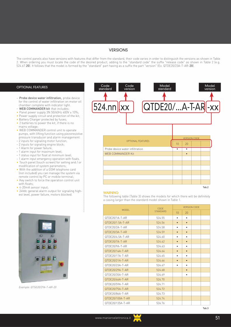
www.manieroelettronica.it 51
WARNINGThe following table (Table 3) shows the models for which there will be definitely a casing larger than the standard model shown in Table 1.
VERSIONS
The control panels also have versions with features that differ from the standard, their code varies in order to distinguish the versions as shown in Table 2. When ordering you must locate the code of the desired product, adding to the "standard code" the suffix "release code" as shown in Table 2 (e.g. 524.67.20). It follows that the model is formed by the "standard" part having as a suffix the part "version" (Ex. QTDE20/23A-T-AR-20).
OPTIONAL FEATURES
– Probe device water infiltration, probe device for the control of water infiltration on motor oil chamber complete with indicator light.
– WEB COMMANDER kit that includes:• Panel power supply 3N 50/60Hz 400V ± 10%;• Power supply circuit and protection of the kit;• Battery Charger protected by fuses;• 2 batteries to power the kit, if there is no
mains voltage;• WEB COMMANDER control unit to operate
pumps, with lifting function using piezoresistive pressure transducer and alarm management:
– 2 inputs for signaling motor function;– 2 inputs for signaling engine block;– 1 Alarm for power failure;– 1 alarm input for maximum level;– 1 status input for float at minimum level;– 1 alarm input emergency operation with floats.• Touch panel (touch screen) for setting and / or
modification of system parameters;• With the addition of a GSM telephone card
(not included) you can manage the system via remote control by PC or mobile terminal;
• Key switch to force the operation control unit with floats;
• 4-20mA sensor input;• 24Vdc general alarm output for signaling high-
est level, power failure, motors blocked.
Codestandard
Codeversion
Modelstandard
Modelversion
524.nn .xx QTDE20/...A-T-AR -xx
OPTIONAL FEATURESVERSION CODE
10 20
Probe device water infiltration • •
WEB COMMANDER Kit •
Tab.2
MODELCODE
STANDARD
VERSION CODE
10 20
QTDE20/1A-T-AR 524.55 • •
QTDE20/1.5A-T-AR 524.56 • •
QTDE20/2A-T-AR 524.58 • •
QTDE20/3A-T-AR 524.59 • •
QTDE20/4.5A-T-AR 524.60 • •
QTDE20/7A-T-AR 524.62 • •
QTDE20/9A-T-AR 524.63 • •
QTDE20/14A-T-AR 524.64 • •
QTDE20/17A-T-AR 524.65 • •
QTDE20/21A-T-AR 524.66 • •
QTDE20/23A-T-AR 524.67 • •
QTDE20/29A-T-AR 524.68 •
QTDE20/35A-T-AR 524.69 •
QTDE20/46A-T-AR 524.70
QTDE20/59A-T-AR 524.71
QTDE20/75A-T-AR 524.72
QTDE20/86A-T-AR 524.73
QTDE20/100A-T-AR 524.74
QTDE20/135A-T-AR 524.76
Tab.3
Example: QTSE20/29A-T-AR-20
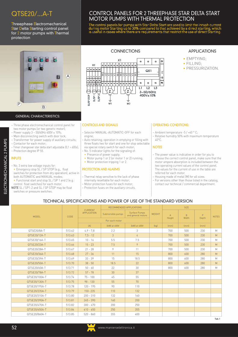
www.manieroelettronica.it52
A
BP
CONNECTIONS APPLICATIONS
QTSE20/...A-TThreephase ElectromechanicalStar Delta Starting control panelfor 2 motor pumps with Thermalprotection
– Three phase electromechanical control panel for two motor pumps (or two generic motor);
– Power supply 3 ~ 50/60Hz 400V ± 10%;– Main disconnecting switch with door lock;– Transformer for power supply of auxiliary circuits;– Contactor for each motor;– Timer changeover star delta start adjustable (0,1 ÷ 600s);– Protection degree IP 55.
INPUTS
– No. 3 extra low voltage inputs for: • Emergency stop SL / SP STOP (e.g., float
switches for protection from dry operation), active in both AUTOMATIC and MANUAL modes;
• Functional start and stop SL / SP 1 and 2 (e.g.: control float switches) for each motor.
NOTE SL / SP1-2 and SL / SP STOP may be float switches or pressure switches.
CONTROLS AND SIGNALS
– Selector MANUAL-AUTOMATIC-OFF for each engine;
– Auto retaining; operation in emptying or filling with three floats two for start and one for stop selectable via special rotary switch for each motor;
– No. 5 indicator lights for the signaling of: • Presence of power supply; • Motor pump 1 or 2 (or motor 1 or 2) running; • Motor protection tripping 1 or 2.
PROTECTION AND ALARMS
– Thermal relay sensitive to the lack of phase internally resettable for each motor;
– Motor protection fuses for each motor;– Protection fuses on the auxiliary circuits.
OPERATING CONDITIONS:
– Ambient temperature -5 / +40 ° C;– Relative humidity 50% with maximum temperature
40°C.
NOTES
– The power value is indicative in order for you to choose the correct control panel, make sure that the motor ampere absorption is included between the two operating current values of the control panel. The values for the current of use in the table are referred for each motor.
– Housing made of metal (M) for all sizes.– For versions other than those listed in the catalog,
contact our technical / commercial department.
• EMPTYING;
• FILLING;
• PRESSURIZATION.
GENERAL CHARACTERISTICS:
TECHNICAL SPECIFICATIONS AND POWER OF USE OF THE STANDARD VERSION
MODEL CODE
CURRENTAPPLICATION
RECOMMENDED APPLICATIONS
WEIGHT
SIZE
NOTESSubmersible pumps
Surface Pumpsand general motors A
HeightB
WidthP
DepthFor each motor
(A) (kW) at 400V (kW) at 400V (kg) (mm) (mm) (mm)
QTSE20/8A-T 513.62 4,9 - 7,8 2.2 3 700 500 230 M
QTSE20/12A-T 513.63 7,5 - 12 3 4 700 500 230 M
QTSE20/16A-T 513.65 10 - 16 5.5 7.5 700 500 230 M
QTSE20/23A-T 513.66 15 - 23 7.5 9 700 500 230 M
QTSE20/28A-T 513.67 21 - 28 9 11 700 500 230 M
QTSE20/36A-T 513.68 27 - 36 11 15 800 600 280 M
QTSE20/39A-T 513.69 33 - 39 15 18.5 800 600 280 M
QTSE20/50A-T 513.70 38 - 50 18.5 22 800 600 280 M
QTSE20/60A-T 513.71 50 - 60 22 30 800 600 280 M
QTSE20/78A-T 513.72 57 - 78 30 37
QTSE20/100A-T 513.74 75 - 100 45 55
QTSE20/130A-T 513.75 98 - 130 55 70
QTSE20/195A-T 513.78 120 - 195 90 110
QTSE20/235A-T 513.79 150- 235 110 132
QTSE20/310A-T 513.80 200 - 310 132 160
QTSE20/390A-T 513.81 245 - 390 160 200
QTSE20/470A-T 513.82 300 - 470 200 250
QTSE20/650A-T 513.84 410 - 650 250 355
QTSE20/860A-T 513.85 520 - 860 355 400
Tab.1
QS1
L1 L2 L33~50/60Hz 400V±10%
PE
SL/S
P ST
OP
SL/S
P 1
1 2 3 4 5SL
/SP
2
X2
W2
U2
V2
U1
V1
W2
U2
V2
U1
V1
W1
W1
X1
M1 M2
ELEC
TRO
MEC
HA
NIC
AL
2 PU
MPS
CONTROL PANELS FOR 2 THREEPHASE STAR DELTA START MOTOR PUMPS WITH THERMAL PROTECTIONThe control panels for pumps with Star Delta Start are used to limit the inrush current during motor Starting up to 30% compared to that achieved by a direct starting, which is useful in cases where there are requirements that restrict the use of direct Starting.
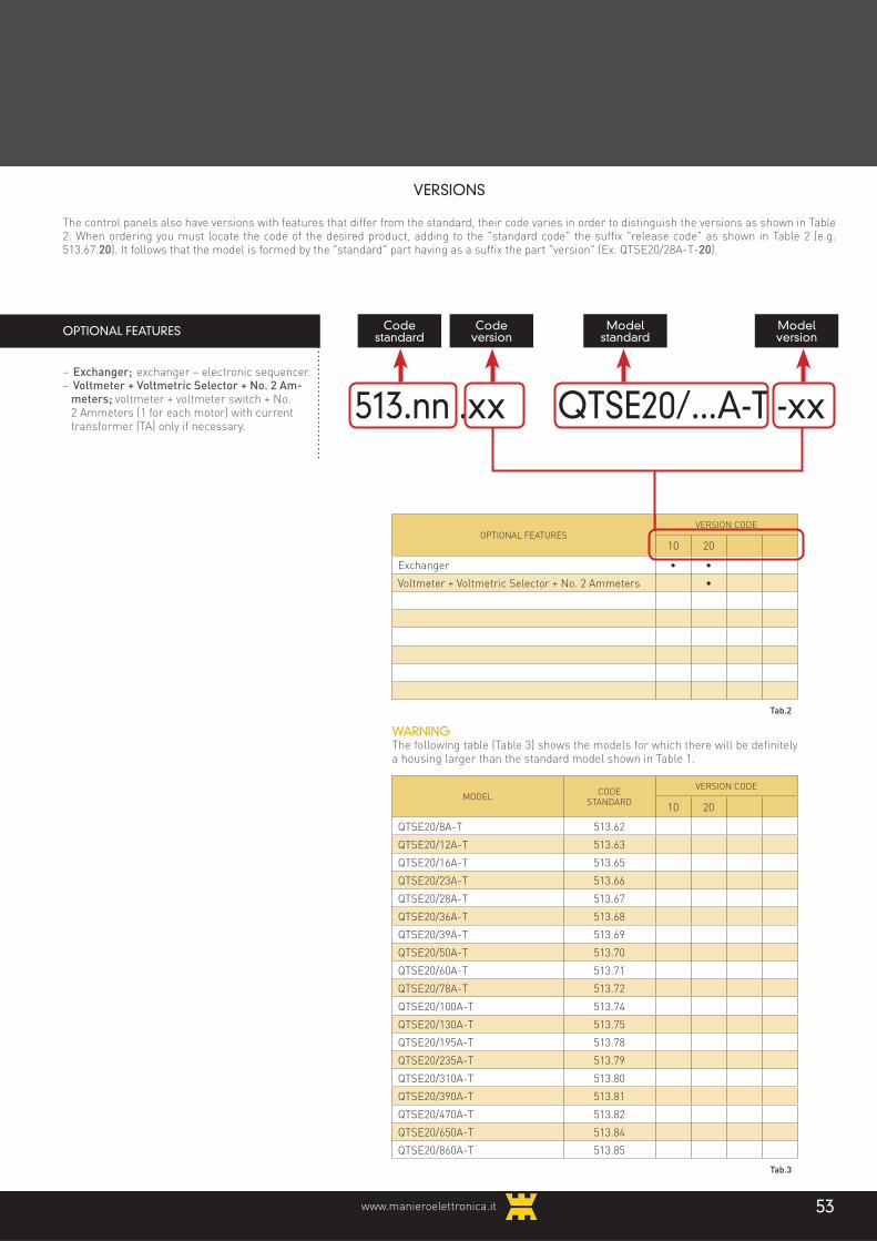
www.manieroelettronica.it 53
WARNINGThe following table (Table 3) shows the models for which there will be definitely a housing larger than the standard model shown in Table 1.
VERSIONS
The control panels also have versions with features that differ from the standard, their code varies in order to distinguish the versions as shown in Table 2. When ordering you must locate the code of the desired product, adding to the "standard code" the suffix "release code" as shown in Table 2 (e.g. 513.67.20). It follows that the model is formed by the "standard" part having as a suffix the part "version" (Ex. QTSE20/28A-T-20).
OPTIONAL FEATURES
– Exchanger; exchanger – electronic sequencer.– Voltmeter + Voltmetric Selector + No. 2 Am-
meters; voltmeter + voltmeter switch + No. 2 Ammeters (1 for each motor) with current transformer (TA) only if necessary.
Codestandard
Codeversion
Modelstandard
Modelversion
513.nn .xx QTSE20/...A-T -xx
OPTIONAL FEATURESVERSION CODE
10 20
Exchanger • •
Voltmeter + Voltmetric Selector + No. 2 Ammeters •
Tab.2
MODELCODE
STANDARD
VERSION CODE
10 20
QTSE20/8A-T 513.62
QTSE20/12A-T 513.63
QTSE20/16A-T 513.65
QTSE20/23A-T 513.66
QTSE20/28A-T 513.67
QTSE20/36A-T 513.68
QTSE20/39A-T 513.69
QTSE20/50A-T 513.70
QTSE20/60A-T 513.71
QTSE20/78A-T 513.72
QTSE20/100A-T 513.74
QTSE20/130A-T 513.75
QTSE20/195A-T 513.78
QTSE20/235A-T 513.79
QTSE20/310A-T 513.80
QTSE20/390A-T 513.81
QTSE20/470A-T 513.82
QTSE20/650A-T 513.84
QTSE20/860A-T 513.85
Tab.3

www.manieroelettronica.it54
A
BP
CONNECTIONS APPLICATIONS
QTSE20/...A-T-ARThreephase Electromechanical Star Delta Starting control panel for 2motor pumps with Thermalprotection for Waste Water
– Three phase electromechanical control panel for two motor pumps:
– Power supply 3 ~ 50/60Hz 400V ± 10%;– Main disconnecting switch with door lock;– Transformer for power supply of auxiliary circuits;– Contactor for each motor;– Timer changeover Star Delta Star adjustable (0,1 ÷
600s) for each motor;– Exchanger;– Protection degree IP 55.
INPUTS
– No. 6 extra low voltage inputs for: • Emergency stop SL / SP STOP (e.g, float switches
for protection from dry operation), active in both AUTOMATIC and MANUAL modes;
• Functional start and stop SL / SP 1 and 2 (e.g.: control float switches);
• maximum level alarm SL / SP MAX; • engine block due to temperature sensor tripping.
CONTROLS AND SIGNALS
– Selector MANUAL-AUTOMATIC-OFF for each engine;– No. 5 indicator lights for the signaling of: • Presence of power supply; • Motor pump 1 or 2 running; • Motor protection tripping 1 or 2.
PROTECTION AND ALARMS
– Thermal relay sensitive to the lack of phase internally resettable for each motor;
– Motor protection fuses for each motor;– Protection fuses on the auxiliary circuits;– Alarm output 24Vac active in case of overload protec-
tion tripping or maximum level reached.
– Engine block due to temperature sensor tripping.
OPERATING CONDITIONS:
– Ambient temperature -5 / +40 ° C;– Relative humidity 50% with maximum temperature
40°C.
NOTES
– The power value is indicative in order for you to choose the correct control panel, make sure that the motor ampere absorption is included between the two operating current values of the control panel. The values for the current of use in the table are referred for each motor.
– Housing made of metal (M) for all sizes.– For versions other than those listed in the catalog,
contact our technical / commercial department.
• EMPTYING.
GENERAL CHARACTERISTICS:
TECHNICAL SPECIFICATIONS AND POWER OF USE OF THE STANDARD VERSION
MODEL CODE
CURRENTAPPLICATION
RECOMMENDED APPLICATIONS
WEIGHT
SIZE
NOTESSubmersible pumps
Surface Pumpsand general motors A
HeightB
WidthP
DepthFor each motor
(A) (kW) at 400V (kW) at 400V (kg) (mm) (mm) (mm)
QTSE20/8A-T-AR 519.62 4,9 - 7,8 2.2 3 700 500 230 M
QTSE20/12A-T-AR 519.63 7,5 - 12 3 4 700 500 230 M
QTSE20/16A-T-AR 519.65 10 - 16 5.5 7.5 700 500 230 M
QTSE20/23A-T-AR 519.66 15 - 23 7.5 9 700 500 230 M
QTSE20/28A-T-AR 519.67 21 - 28 9 11 700 500 230 M
QTSE20/36A-T-AR 519.68 27 - 36 11 15 800 600 280 M
QTSE20/39A-T-AR 519.69 33 - 39 15 18.5 800 600 280 M
QTSE20/50A-T-AR 519.70 38 - 50 18.5 22 800 600 280 M
QTSE20/60A-T-AR 519.71 50 - 60 22 30 800 600 280 M
QTSE20/78A-T-AR 519.72 57 - 78 30 37
QTSE20/100A-T-AR 519.74 75 - 100 45 55
QTSE20/130A-T-AR 519.75 98 - 130 55 70
QTSE20/195A-T-AR 519.78 120 - 195 90 110
QTSE20/235A-T-AR 519.79 150- 235 110 132
QTSE20/310A-T-AR 519.80 200 - 310 132 160
QTSE20/390A-T-AR 519.81 245 - 390 160 200
QTSE20/470A-T-AR 519.82 300 - 470 200 250
QTSE20/650A-T-AR 519.84 410 - 650 250 355
QTSE20/860A-T-AR 519.85 520 - 860 355 400
Tab.1
ELEC
TRO
MEC
HA
NIC
AL
2 PU
MPS
CONTROL PANELS FOR 2 THREE PHASE STARTING MOTOR PUMPS STAR DELTA START WITH THERMAL PROTECTIONThe control panels for pumps with Star Delta Start are used to limit the inrush current during motor Starting up to 30% compared to that achieved by a direct starting, which is useful in cases where there are requirements that restrict the use of direct Starting. For specific use in waste water discharge, we propose control panels for three-phase pumps that can run either bulb-type floats or normal floats.

www.manieroelettronica.it 55
WARNINGThe following table (Table 3) shows the models for which there will be definitely a housing larger than the standard model shown in Table 1.
VERSIONS
The control panels also have versions with features that differ from the standard, their code varies in order to distinguish the versions as shown in Table 2. When ordering you must locate the code of the desired product, adding to the "standard code" the suffix "release code" as shown in Table 2 (e.g. 519.67.20). It follows that the model is formed by the "standard" part having as a suffix the part "version" (Ex. QTDE20/28A-T-AR-20).
OPTIONAL FEATURES
– Probe device water infiltration, probe device for the control of water infiltration on motor oil chamber complete with indicator light.
– WEB COMMANDER kit that includes:• Panel power supply 3N 50/60Hz 400V ± 10%;• Power supply circuit and protection of the kit;• Battery Charger protected by fuses;• 2 batteries to power the kit, if there is no
mains voltage;• WEB COMMANDER control unit to operate
pumps, with lifting function using piezoresistive pressure transducer and alarm management:– 2 inputs for signaling motor function;– 2 inputs for signaling engine block;– 1 Alarm for power failure;– 1 alarm input for maximum level;– 1 status input for float at minimum level;– 1 alarm input emergency operation with floats.
• Touch panel (touch screen) for setting and / or modification of system parameters;
• With the addition of a GSM telephone card (not included) you can manage the system via remote control by PC or mobile terminal;
• Key switch to force the operation control unit with floats;
• 4-20mA sensor input;• 24Vdc general alarm output for signaling high-
est level, power failure, motors blocked.
Codestandard
Codeversion
Modelstandard
Modelversion
519.nn .xx QTSE20/...A-T-AR -xx
OPTIONAL FEATURESVERSION CODE
10 20
Probe device water infiltration • •
WEB COMMANDER Kit •
Tab.2
MODELCODE
STANDARD
VERSION CODE
10 20
QTSE20/8A-T-AR 519.62
QTSE20/12A-T-AR 519.63
QTSE20/16A-T-AR 519.65
QTSE20/23A-T-AR 519.66
QTSE20/28A-T-AR 519.67
QTSE20/36A-T-AR 519.68
QTSE20/39A-T-AR 519.69
QTSE20/50A-T-AR 519.70
QTSE20/60A-T-AR 519.71
QTSE20/78A-T-AR 519.72
QTSE20/100A-T-AR 519.74
QTSE20/130A-T-AR 519.75
QTSE20/195A-T-AR 519.78
QTSE20/235A-T-AR 519.79
QTSE20/310A-T-AR 519.80
QTSE20/390A-T-AR 519.81
QTSE20/470A-T-AR 519.82
QTSE20/650A-T-AR 519.84
QTSE20/860A-T-AR 519.85
Tab.3
Example: QTSE20/28A-T-AR-20

www.manieroelettronica.it56
A
BP
CONNECTIONS APPLICATIONS
QTDE30/...A-TThreephase Direct startingElectromechanical control panelfor 3 motor pumps with Thermalprotection
– Three phase electromechanical control panel for three motor pumps (or two generic motor);
– Power supply 3 ~ 50/60Hz 400V ± 10%;– Main disconnecting switch with door lock;– Transformer for power supply of auxiliary
circuits;– Contactor for each motor;– Protection degree IP 55.
INPUTS
– No. 4 low voltage inputs for: • Emergency stop SL / SP STOP (e.g., float
switches for protection from dry operation), active in both AUTOMATIC and MANUAL modes;
• Functional start and stop SL / SP 1 ÷ 3 (e.g.: control float switches) for each motor.
NOTE SL/SP1 ÷ 3 and SL / SP STOP may be float switches or pressure switches.
CONTROLS AND SIGNALS
– Selector MANUAL-AUTOMATIC-OFF for each engine;
– Auto retaining; operation in emptying or filling with four floats three for start and one for stop selectable via special rotary switch for each motor;
– No. 7 indicator lights for the signaling of: • Presence of power supply; • Motor pump 1 ÷ 3 (or motor 1 ÷ 3) running; • Motor protection tripping 1 ÷ 3.
PROTECTION AND ALARMS
– Thermal relay sensitive to the lack of phase internally resettable for each motor;
– Motor protection fuses for each motor;– Protection fuses on the auxiliary circuits.
OPERATING CONDITIONS:
– Ambient temperature -5 / +40 ° C;– Relative humidity 50% with maximum
temperature 40°C.
NOTES
– The power value is indicative in order for you to choose the correct control panel, make sure that the motor ampere absorption is included between the two operating current values of the control panel.
– Casing made of thermoplastic material up to size 9A in metal (M) for all other sizes.
– For versions other than those listed in the catalog, contact our technical / commercial department.
• EMPTYING;
• FILLING;
• PRESSURIZATION.
GENERAL CHARACTERISTICS:
QS1
L1 L2 L33~50/60Hz 400V±10%
PE
T1 T2 T3
FS2
U V W
T1 T2 T3
FS1
U V W
SL/S
P ST
OP
SL/S
P 1
1 2 3 4 5SL
/SP
2
X1
6
SL/S
P 3
T1 T2 T3
FS3
U V W
7 8
M1 M2 M3
TECHNICAL SPECIFICATIONS AND POWER OF USE OF THE STANDARD VERSION
MODEL CODE
CURRENTAPPLICATION
RECOMMENDED APPLICATIONS
WEIGHT
SIZE
NOTESSubmersible pumps
Surface Pumpsand general motors A
HeightB
WidthP
DepthFor each motor
(A) (kW) at 400V (kW) at 400V (kg) (mm) (mm) (mm)
QTDE30/1A-T 516.55 0,6 - 0,9 0.18 0.25 8.5 460 380 150 P
QTDE30/1.5A-T 516.56 0,9 - 1,4 0.25 0.37 8.5 460 380 150 P
QTDE30/2A-T 516.58 1,3 - 2,1 0.37 0.75 8.5 460 380 150 P
QTDE30/3A-T 516.59 1,9 - 3 0.75 1.1 8.5 460 380 150 P
QTDE30/4.5A-T 516.60 2,9 - 4,5 1.1 1.5 8.5 460 380 150 P
QTDE30/7A-T 516.62 4,3 - 6,8 1.5 3 8.5 460 380 150 P
QTDE30/9A-T 516.63 5,7 - 9,1 3 4 8.5 460 380 150 P
QTDE30/14A-T 516.64 8,6 - 13,5 4 5.5 22 500 400 230 M
QTDE30/17A-T 516.65 12,5 - 16,5 5.5 7.5 22 500 400 230 M
QTDE30/21A-T 516.66 16 - 21 7.5 9 22 500 400 230 M
QTDE30/23A-T 516.67 19 - 23 9 11 22 500 400 230 M
QTDE30/29A-T 516.68 22 - 29 11 15
QTDE30/35A-T 516.69 29 - 35 15 18.5
QTDE30/46A-T 516.70 33 - 46 18.5 22
QTDE30/59A-T 516.71 44 - 59 22 30
QTDE30/75A-T 516.72 57 - 75 30 37
QTDE30/86A-T 516.73 68 - 86 37 45
QTDE30/100A-T 516.74 85 - 100 45 55
QTDE30/135A-T 516.76 85 - 135 55 75
Tab.1
ELEC
TRO
MEC
HA
NIC
AL
3 PU
MPS
CONTROL PANELS FOR 3 THREE PHASE MOTOR PUMPSDIRECT STARTING WITH THERMAL PROTECTION

www.manieroelettronica.it 57
WARNINGThe following table (Table 3) shows the models for which there will be definitely a housing larger than the standard model shown in Table 1.
VERSIONS
The control panels also have versions with features that differ from the standard, their code varies in order to distinguish the versions as shown in Table 2. When ordering you must locate the code of the desired product, adding to the "standard code" the suffix "release code" as shown in Table 2 (e.g. 516.67.20). It follows that the model is formed by the "standard" part having as a suffix the part "version" (Ex. QTDE30/23A-T-20).
OPTIONAL FEATURES
– Exchanger; exchanger – electronic sequencer.– Voltmeter + Volt. Switch + No. 3 Ammeters;
voltmeter + voltmeter switch + No. 3 Ammeters (1 for each motor) with current transformer (TA) only if necessary.
Codestandard
Codeversion
Modelstandard
Modelversion
516.nn .xx QTDE30/...A-T -xx
OPTIONAL FEATURESVERSION CODE
10 20
Exchanger • •
Voltmeter + Volt. Switch + No. 3 Ammeters •
Tab.2
MODELCODE
STANDARD
VERSION CODE
10 20
QTDE30/1A-T 516.55
QTDE30/1.5A-T 516.56
QTDE30/2A-T 516.58
QTDE30/3A-T 516.59
QTDE30/4.5A-T 516.60
QTDE30/7A-T 516.62
QTDE30/9A-T 516.63
QTDE30/14A-T 516.64
QTDE30/17A-T 516.65
QTDE30/21A-T 516.66
QTDE30/23A-T 516.67
QTDE30/29A-T 516.68
QTDE30/35A-T 516.69
QTDE30/46A-T 516.70
QTDE30/59A-T 516.71
QTDE30/75A-T 516.72
QTDE30/86A-T 516.73
QTDE30/100A-T 516.74
QTDE30/135A-T 516.76
Tab.3

www.manieroelettronica.it58
A
BP
CONNECTIONS APPLICATIONS
QTDE30/...A-T-ARThreephase Direct StartingElectromechanical control panel for 3 motor pumps with Thermalprotection for Waste Water
– Three phase electromechanical control panel for three motor pumps:
– Power supply 3 ~ 50/60Hz 400V ± 10%;– Main disconnecting switch with door lock;– Transformer for power supply of auxiliary circuits;– Contactor for each motor;– Exchanger;– Protection degree IP 55.
INPUTS
– No. 8 low voltage inputs for: • Emergency stop SL / SP STOP (e.g, float
switches for protection from dry operation), active in both AUTOMATIC and MANUAL modes;
• Functional start and stop SL / SP 1 ÷ 3 (e.g.: control float switches) for each motor.
• Maximum level alarm SL / SP MAX; • Engine block due to temperature sensor tripping.
CONTROLS AND SIGNALS
– Selector MANUAL-AUTOMATIC-OFF for each engine;
– No. 7 indicator lights for the signaling of: • Presence of power supply; • Motor pump 1 ÷ 3 running; • Motor protection tripping 1 ÷ 3.
PROTECTION AND ALARMS
– Motor protection fuses for each motor;– Protection fuses on the auxiliary circuits.– Alarm output 24Vac active in case of overload
protection tripping or maximum level reached.– Engine block due to temperature sensor tripping.
OPERATING CONDITIONS:
– Ambient temperature -5 / +40 ° C;– Relative humidity 50% with maximum temperature
40°C.
NOTES
– The power value is indicative in order for you to choose the correct control panel, make sure that the motor ampere absorption is included between the two operating current values of the control panel.
– Housing made of metal (M) for all sizes.– For versions other than those listed in the catalog,
contact our technical / commercial department.
• EMPTYING.
GENERAL CHARACTERISTICS:
TECHNICAL SPECIFICATIONS AND POWER OF USE OF THE STANDARD VERSION
MODEL CODE
CURRENTAPPLICATION
RECOMMENDED APPLICATIONS
WEIGHT
SIZE
NOTES
Submersible pumpsSurface Pumps
and general motors AHeight
BWidth
PDepth
For each motor
(A) (kW) at 400V (kW) at 400V (kg) (mm) (mm) (mm)
QTDE30/1A-T-AR 525.55 0,6 - 0,9 0.18 0.25 23 500 400 230 M
QTDE30/1.5A-T-AR 525.56 0,9 - 1,4 0.25 0.37 23 500 400 230 M
QTDE30/2A-T-AR 525.58 1,3 - 2,1 0.37 0.75 23 500 400 230 M
QTDE30/3A-T-AR 525.59 1,9 - 3 0.75 1.1 23 500 400 230 M
QTDE30/4.5A-T-AR 525.60 2,9 - 4,5 1.1 1.5 23 500 400 230 M
QTDE30/7A-T-AR 525.62 4,3 - 6,8 1.5 3 23 500 400 230 M
QTDE30/9A-T-AR 525.63 5,7 - 9,1 3 4 23 500 400 230 M
QTDE30/14A-TAR 525.64 8,6 - 13,5 4 5.5 700 500 230 M
QTDE30/17A-T-AR 525.65 12,5 - 16,5 5.5 7.5 700 500 230 M
QTDE30/21A-T-AR 525.66 16 - 21 7.5 9 700 500 230 M
QTDE30/23A-T-AR 525.67 19 - 23 9 11 700 500 230 M
QTDE30/29A-T-AR 525.68 22 - 29 11 15
QTDE30/35A-T-AR 525.69 29 - 35 15 18.5
QTDE30/46A-T-AR 525.70 33 - 46 18.5 22
QTDE30/59A-T-AR 525.71 44 - 59 22 30
QTDE30/75A-T-AR 525.72 57 - 75 30 37
QTDE30/86A-T-AR 525.73 68 - 86 37 45
QTDE30/100A-T-AR 525.74 85 - 100 45 55
QTDE30/135A-T-AR 525.76 85 - 135 55 75
Tab.1
ELEC
TRO
MEC
HA
NIC
AL
3 PU
MPS
CONTROL PANELS FOR 3 THREE PHASE MOTOR PUMPSDIRECT STARTING WITH THERMAL PROTECTIONFOR WASTEWATERFor specific use in waste water discharge, we propose control panels for three-phase pumps that can run either bulb-type floats or normal floats. For any other specific need, as usual, please contact our technical service / sales service.

www.manieroelettronica.it 59
WARNINGThe following table (Table 3) shows the models for which there will be definitely a housing larger than the standard model shown in Table 1.
VERSIONS
The control panels also have versions with features that differ from the standard, their code varies in order to distinguish the versions as shown in Table 2. When ordering you must locate the code of the desired product, adding to the "standard code" the suffix "release code" as shown in Table 2 (e.g. 525.67.10). It follows that the model is formed by the "standard" part having as a suffix the part "version" (Ex. QTDE30/23A-T-AR+DS).
OPTIONAL FEATURES
– Probe device water infiltration, probe device for the control of water infiltration on motor oil chamber complete with indicator light.
Codestandard
Codeversion
Modelstandard
Modelversion
525.nn .10 QTDE30/...A-T-AR -DS
OPTIONAL FEATURESVERSION CODE
10
Probe device water infiltration •
Tab.2
MODELCODE
STANDARD
VERSION CODE
10
QTDE30/1A-T-AR 525.55
QTDE30/1.5A-T-AR 525.56
QTDE30/2A-T-AR 525.58
QTDE30/3A-T-AR 525.59
QTDE30/4.5A-T-AR 525.60
QTDE30/7A-T-AR 525.62
QTDE30/9A-T-AR 525.63
QTDE30/14A-T-AR 525.64
QTDE30/17A-T-AR 525.65
QTDE30/21A-T-AR 525.66
QTDE30/23A-T-AR 525.67
QTDE30/29A-T-AR 525.68
QTDE30/35A-T-AR 525.69
QTDE30/46A-T-AR 525.70
QTDE30/59A-T-AR 525.71
QTDE30/75A-T-AR 525.72
QTDE30/86A-T-AR 525.73
QTDE30/100A-T-AR 525.74
QTDE30/135A-T-AR 525.76
Tab.3

www.manieroelettronica.it60
A
BP
CONNECTIONS APPLICATIONS
QTSE30/...A-TThreephase ElectromechanicalStar Delta Starting control panelfor 3 motor pumps with Thermal protection
– Three phase electromechanical control panel for three motor pumps (or two generic motor);
– Power supply 3 ~ 50/60Hz 400V ± 10%;– Main disconnecting switch with door lock;– Transformer for power supply of auxiliary circuits;– Contactor for each motor;– Timer changeover star delta start adjustable (0,1
÷ 600s);– Protection degree IP 55.
INPUTS
– No. 4 extra low voltage inputs for: • Emergency stop SL / SP STOP (e.g, float
switches for protection from dry operation), active in both AUTOMATIC and MANUAL modes;
• Functional start and stop SL / SP 1 ÷ 3 (e.g.: control float switches) for each motor.
NOTE SL/SP1 ÷ 3 and SL / SP STOP may be float switches or pressure switches.
CONTROLS AND SIGNALS
– Selector MANUAL-AUTOMATIC-OFF for each engine;
– Auto retaining; operation in emptying or filling with four floats three for start and one for stop select-able via special rotary switch for each motor;
– No. 7 indicator lights for the signaling of: • Presence of power supply; • Motor pump 1 ÷ 3 (or motor 1 ÷ 3) running; • Motor protection tripping 1 ÷ 3. PROTECTION AND ALARMS
– Thermal relay sensitive to the lack of phase inter-nally resettable for each motor;
– Motor protection fuses for each motor;– Protection fuses on the auxiliary circuits.
OPERATING CONDITIONS:
– Ambient temperature -5 / +40 ° C;– Relative humidity 50% with maximum temperature
40°C.
NOTES
– The power value is indicative in order for you to choose the correct control panel, make sure that the motor ampere absorption is included between the two operating current values of the control panel.
– Housing made of metal (M) for all sizes.– For versions other than those listed in the catalog,
contact our technical / commercial department.
GENERAL CHARACTERISTICS:
QS1
L1 L2 L33~50/60Hz 400V±10%
PE
W2
U2
V2
U1
V1
W1
X1
W2
U2
V2
U1
V1
W1
M 2 M 3
W2
U2
V2
U1
V1
W1
M 1SL/S
P ST
OP
SL/S
P 1
1 2 3 4 5SL
/SP
2
X2
6
SL/S
P 3
7 8
TECHNICAL SPECIFICATIONS AND POWER OF USE OF THE STANDARD VERSION
MODEL CODE
CURRENTAPPLICATION
RECOMMENDED APPLICATIONS
WEIGHT
SIZE
Submersible pumpsSurface Pumps
and general motors AHeight
BWidth
PDepth
For each motor
(A) (kW) at 400V (kW) at 400V (kg) (mm) (mm) (mm)
QTSE30/8A-T 515.62 4,9 - 7,8 2.2 3
QTSE30/12A-T 515.63 7,5 - 12 3 4
QTSE30/16A-T 515.65 10 - 16 5.5 7.5
QTSE30/23A-T 515.66 15 - 23 7.5 9
QTSE30/28A-T 515.67 21 - 28 9 11
QTSE30/36A-T 515.68 27 - 36 11 15
QTSE30/39A-T 515.69 33 - 39 15 18.5
QTSE30/50A-T 515.70 38 - 50 18.5 22
QTSE30/60A-T 515.71 50 - 60 22 30
QTSE30/78A-T 515.72 57 - 78 30 37
QTSE30/100A-T 515.74 75 - 100 45 55
QTSE30/130A-T 515.75 98 - 130 55 70
QTSE30/195A-T 515.78 120 - 195 90 110
QTSE30/235A-T 515.79 150- 235 110 132
QTSE30/310A-T 515.80 200 - 310 132 160
QTSE30/390A-T 515.81 245 - 390 160 200
QTSE30/470A-T 515.82 300 - 470 200 250
QTSE30/650A-T 515.84 410 - 650 250 355
QTSE30/860A-T 515.85 520 - 860 355 400
Tab.1
• EMPTYING;
• FILLING;
• PRESSURIZATION.
ELEC
TRO
MEC
HA
NIC
AL
3 PU
MPS
CONTROL PANELS FOR 3 THREE PHASE MOTOR PUMPS STAR DELTA START WITH THERMAL PROTECTIONThe control panels for pumps with Star Delta Start are used to limit the inrush current during motor Starting up to 30% compared to that achieved by a direct starting, which is useful in cases where there are requirements that restrict the use of direct Starting.

www.manieroelettronica.it 61
WARNINGThe following table (Table 3) shows the models for which there will be definitely a housing larger than the standard model shown in Table 1.
VERSIONS
The control panels also have versions with features that differ from the standard, their code varies in order to distinguish the versions as shown in Table 2. When ordering you must locate the code of the desired product, adding to the "standard code" the suffix "release code" as shown in Table 2 (e.g. 515.67.40). It follows that the model is formed by the "standard" part having as a suffix the part "version" (Ex. QTDE30/28A-T-40).
OPTIONAL FEATURES
– Exchanger; exchanger – electronic sequencer.– Voltmeter + Voltmetric Selector + No. 3 Am-
meters; voltmeter + voltmeter switch + No. 3 Ammeters (1 for each motor) with current transformer (TA) only if necessary.
Codestandard
Codeversion
Modelstandard
Modelversion
515.nn .xx QTSE30/...A-T -xx
OPTIONAL FEATURESVERSION CODE
10 20
Exchanger • •
Voltmeter + Voltmetric Selector + No. 3 Ammeters •
Tab.2
MODELCODE
STANDARD
VERSION CODE
10 20
QTSE30/8A-T 515.62
QTSE30/12A-T 515.63
QTSE30/16A-T 515.65
QTSE30/23A-T 515.66
QTSE30/28A-T 515.67
QTSE30/36A-T 515.68
QTSE30/39A-T 515.69
QTSE30/50A-T 515.70
QTSE30/60A-T 515.71
QTSE30/78A-T 515.72
QTSE30/100A-T 515.74
QTSE30/130A-T 515.75
QTSE30/195A-T 515.78
QTSE30/235A-T 515.79
QTSE30/310A-T 515.80
QTSE30/390A-T 515.81
QTSE30/470A-T 515.82
QTSE30/650A-T 515.84
QTSE30/860A-T 515.85
Tab.3

www.manieroelettronica.it62
A
BP
CONNECTIONS APPLICATIONS
QTSE30/...A-T-ARThreephase Electromechanical Star Delta Start control panel for 3 motor pumps with Thermal protection for Waste Water
– Three phase electromechanical control panel for three motor pumps:
– Power supply 3 ~ 50/60Hz 400V ± 10%;– Main disconnecting switch with door lock;– Transformer for power supply of auxiliary circuits;– Contactor for each motor;– Timer changeover star delta star adjustable (0,1 ÷ 600s);– Exchanger;– Protection degree IP 55.
INPUTS
– No. 8 extra low voltage inputs for: • Emergency stop SL / SP STOP (e.g, float switches
for protection from dry operation), active in both AUTOMATIC and MANUAL modes;
• Functional start and stop SL / SP 1 ÷ 3 (e.g.: control float switches) for each motor.
• Maximum level alarm SL / SP MAX; • Engine block due to temperature sensor tripping.
CONTROLS AND SIGNALS
– Selector MANUAL-AUTOMATIC-OFF for each engine;– No. 7 indicator lights for the signaling of: • Presence of power supply; • Motor pump 1 ÷ 3 running; • Motor protection tripping 1 ÷ 3.
PROTECTION AND ALARMS
– Thermal relay sensitive to the lack of phase internally resettable for each motor;
– Motor protection fuses for each motor;– Protection fuses on the auxiliary circuits.– Alarm output 24Vac active in case of overload protection
tripping or maximum level reached.– Engine block due to temperature sensor tripping.
OPERATING CONDITIONS:
– Ambient temperature -5 / +40 ° C;– Relative humidity 50% with maximum temperature
40°C.
NOTES
– The power value is indicative in order for you to choose the correct control panel, make sure that the motor ampere absorption is included between the two operating current values of the control panel.
– Housing made of metal (M) for all sizes.– For versions other than those listed in the catalog,
contact our technical / commercial department.
• EMPTYING.
GENERAL CHARACTERISTICS:
TECHNICAL SPECIFICATIONS AND POWER OF USE OF THE STANDARD VERSION
MODEL CODE
CURRENTAPPLICATION
RECOMMENDED APPLICATIONS
WEIGHT
SIZE
Submersible pumpsSurface Pumps
and general motors AHeight
BWidth
PDepth
For each motor
(A) (kW) at 400V (kW) at 400V (kg) (mm) (mm) (mm)
QTSE30/8A-T-AR 526.62 4,9 - 7,8 2.2 3
QTSE30/12A-T-AR 526.63 7,5 - 12 3 4
QTSE30/16A-T-AR 526.65 10 - 16 5.5 7.5
QTSE30/23A-T-AR 526.66 15 - 23 7.5 9
QTSE30/28A-T-AR 526.67 21 - 28 9 11
QTSE30/36A-T-AR 526.68 27 - 36 11 15
QTSE30/39A-T-AR 526.69 33 - 39 15 18.5
QTSE30/50A-T-AR 526.70 38 - 50 18.5 22
QTSE30/60A-T-AR 526.71 50 - 60 22 30
QTSE30/78A-T-AR 526.72 57 - 78 30 37
QTSE30/100A-T-AR 526.74 75 - 100 45 55
QTSE30/130A-T-AR 526.75 98 - 130 55 70
QTSE30/195A-T-AR 526.78 120 - 195 90 110
QTSE30/235A-T-AR 526.79 150- 235 110 132
QTSE30/310A-T-AR 526.80 200 - 310 132 160
QTSE30/390A-T-AR 526.81 245 - 390 160 200
QTSE30/470A-T-AR 526.82 300 - 470 200 250
QTSE30/650A-T-AR 526.84 410 - 650 250 355
QTSE30/860A-T-AR 526.85 520 - 860 355 400
Tab.1
ELEC
TRO
MEC
HA
NIC
AL
3 PU
MPS
CONTROL PANELS FOR 3 THREE PHASE MOTOR PUMPS STAR DELTA START WITH THERMAL PROTECTIONThe control panels for pumps with Star Delta Start are used to limit the inrush current during motor Starting up to 30% compared to that achieved by a direct starting, which is useful in cases where there are requirements that restrict the use of direct Starting. For specific use in waste water discharge, we propose control panels for three-phase pumps that can run either bulb-type floats or normal floats.
QS1
L1 L2 L33~50/60Hz 400V±10%
PE
W2
U2
V2
U1
V1
W1
X1
W2
U2
V2
U1
V1
W1
M 2 M 3
W2
U2
V2
U1
V1
W1
M 1
SL/S
P ST
OP
SL/S
P 1
1 2 3 4 5SL
/SP
2
X2
6
SL/S
P 3
7 8 9 10 17 18
SL/S
P M
AX
15 1613 1411 12
AL
°c
PT1
24V~
°c
PT2°c
PT3

www.manieroelettronica.it 63
WARNINGThe following table (Table 3) shows the models for which there will be definitely a housing larger than the standard model shown in Table 1.
VERSIONS
The control panels also have versions with features that differ from the standard, their code varies in order to distinguish the versions as shown in Table 2. When ordering you must locate the code of the desired product, adding to the "standard code" the suffix "release code" as shown in Table 2 (e.g. 526.67.10). It follows that the model is formed by the "standard" part having as a suffix the part "version" (Ex. QTDE30/28A-T-AR+DS).
OPTIONAL FEATURES
– Probe device water infiltration, probe device for the control of water infiltration on motor oil chamber complete with indicator light.
Codestandard
Codeversion
Modelstandard
Modelversion
526.nn .10 QTSE30/...A-T-AR -DS
OPTIONAL FEATURESVERSION CODE
10
Probe device water infiltration •
Tab.2
MODELCODE
STANDARD
VERSION CODE
10
QTSE30/8A-T-AR 526.62
QTSE30/12A-T-AR 526.63
QTSE30/16A-T-AR 526.65
QTSE30/23A-T-AR 526.66
QTSE30/28A-T-AR 526.67
QTSE30/36A-T-AR 526.68
QTSE30/39A-T-AR 526.69
QTSE30/50A-T-AR 526.70
QTSE30/60A-T-AR 526.71
QTSE30/78A-T-AR 526.72
QTSE30/100A-T-AR 526.74
QTSE30/130A-T-AR 526.75
QTSE30/195A-T-AR 526.78
QTSE30/235A-T-AR 526.79
QTSE30/310A-T-AR 526.80
QTSE30/390A-T-AR 526.81
QTSE30/470A-T-AR 526.82
QTSE30/650A-T-AR 526.84
QTSE30/860A-T-AR 526.85
Tab.3

www.manieroelettronica.it64
The new series of fire fighting control panels is in compliance with UNI EN
12845. We offer as standard production a full range of panels for electric pumps
till 132kW featuring several type of starters, as well as service panels and alarm
systems.
Our UNI 12845-compliant direct, star-delta and reactance start control panels are built
in conformity with general EEC standards and they have the following technical features:
• power or phase failure detection alarm systems;
alarm system for signalisation of phase sequence error
• all signal lamps are LEDs for signalling of:
- phase presence of input power supply
- phase presence of motor power supply
- start request
- pump running
- starting failure
• dry contacts outputs for signalling of:
- power supply not available
- start request pump running
- starting failure
• key-operated selector for Automatic – Off - Manual modes;
• start and stop buttons and panel status signal lamps.
• input for 2 pressure switches for pump control;
• input for priming float switch
• input for “pump running” signal pressure switch;
• ammeter;
• voltmeter with selector for phase voltage monitoring.
OUR PRODUCTS
Our panels also include other features as standard which, although not required by
UNI12845, are often extremely important and useful to complete a fire-fighting system:
• Phase failure signalling
• All the outputs are available as switch contacts, but three of them also supply a signal
when the relay is idle (“Power alarm” “Start request” and “start failure” ), and the fourth
function likewise when the relay is energised (“Pump running”).
• If used appropriately, the outputs also signal failures in the connection between the
main panel and the signalling system in the unit monitored.
• Timer for automatic stop of the electric pump for the application in the systems
regulated by UNI 10779:2007 (appendix A) relative to the fuel pumps in the hydrant
network: “Fuel pumps in a hydrant network must have automatic start and manual stop
features, as envisaged by UNI 12845. Wherever deemed necessary, for all activity which
is not constantly monitored, the automatic stop feature is permitted as long as the pump
system is used solely by thehydrant network. In this case, the unit can stop automatically
when the pressure has been maintained above pump start-up pressure constantly for at
least 20 minutes ”.
This function is featured as standard and is activated by microselector.
ADDITIONAL FUNCTIONS AND FEATURES
FIRE PANELSA UNI EN 12845
UNI EN 12845 FIRE FIGHTING SYSTEM CONTROL PANELS

www.manieroelettronica.it 65
A
BP
FLOATS OR PRESSURESWITCHES
POWER SUPPLYINPUT
3 ~ 50/60Hz 400V±10%
MOTOR
INPUT NCALARM
CONTACTS
OUTPUTNC
FOR SIREN
RUNNINGPUMP
OUTPUT
CONNECTION
QTDAS10/...kW-A-2
Fire prevention service direct start Control panel for 1 Three-phase compensation pump with Ammetric protection and Preset Mother Board
THREE-PHASE SERVICE PANELS FOR FIRE-FIGHTING SYSTEMS
Service panels are not required by UNI EN 12845 but they are useful and sometimes even essential for the makeup pump’s operation and to house all those accessories which, although not envisaged by the standard, are often useful in a fire-fighting system.
DESIGNED FOR FITTING OF:
– MCL/3S-300 code 221.05 level control module for 3 level sensors or 2 floats (filling or emptying);– MCL/2ST-300 code 221.04 level control module for 2 timed level sensor (filling or emptying);
N.B.: the modules MCL/3S and MCL/2ST have the function to replace the pressure switch or the minimun level float.
ELECTRONIC SPARE PARTS:
– Mother board Code 223.62;– Synoptic Code 316.03.
OPERATING CONDITIONS:
– Ambient temperature -5/+40°C;– Relative moisture 50% with a max temperature of 40°C.
GENERAL CHARACTERISTICS:
– Control panel with electronic components;– Power supply 3~ 50/60Hz 230/400V ±10%;– Very low voltage input for external control from pressure or float switch;– Very low voltage inputs for external control by float or pressure switch for minimum level control against dry running or too much full;– Selector for pressure switch or minimum level float (contacts NC or NO);– Main pilot light;– Operating motor light;– Protected motor light;– Min/Max water level alarm light;– Selector for automatic-of-manual operation (the last control is not latched);– Electronic protection with adjustable current and cut-in time;– External push-button for ammetric protection reset;– Motor protection fuses;– Auxiliary circuits protection fuses;– General disconnecting switch with door lock;
TECHNICAL DATA AND OPERATING POWERS
MODEL CODEAPPROX
POWER AT 400V kW
APPROX POWER AT
400V Hp
CURRENT ABSORPTION
(A)MIN
CURRENT ABSORPTION
(A) MAXWEIGHT kg
DIMENSIONS mm
A
DIMENSIONS mm
B
DIMENSIONS mm
P
QTDAS10/3,7kW-A-2 246.11 0,55 - 3,7 0,75 - 5 2 8 15 450 300 165
QTDAS10/5kW-A-2 246.12 0,55 - 5 0,75 - 7 2 11 15 450 300 165
QTDAS10/7kW-A-2 246.13 0,55 - 7 0,75 - 9,5 2 16 15 450 300 165
QTDAS10/10kW-A-2 246.14 7,5 - 10 10 - 14 16 22 16 450 300 165
QTDAS10/13,5kW-A-2 246.15 7,5 - 13,5 10 - 18 16 29 16 450 300 165
– Metal box;– Protected to IP 55.

www.manieroelettronica.it66
A
BP
FLOATING PRESSURESWITCHES
POWER SUPPLYINPUT
3 ~ 50/60Hz 400V±10%
MOTOR
STARTINGFAILURE
POWER SUPPLYNOT AVAILABLE
OUTPUT STARTINGREQUEST
RUNNINGPUMP OUTPUT
FLOAT. PRIM.
PRESS.PUMP
RUNNING
CONNECTION
QTDA10/...kW-F-3
UNI EN 12845 rules fire preventiondirect start control panel for1 surpress pump with fusesprotection
UNI EN 12845 FIRE PREVENTION DIRECT START CONTROL PANEL
TECHNICAL DATA AND OPERATING POWERS
MODEL CODEAPPROX
POWER AT 400V kW
APPROX POWER AT
400V Hp
CURRENT ABSORPTION
(A)MIN
CURRENT ABSORPTION
(A) MAXWEIGHT kg
DIMENSIONS mm
A
DIMENSIONS mm
B
DIMENSIONS mm
P
QTDA10/1,5kW-F-3 246.80 0,37 - 1,5 0,5 - 2 1 4,5 14,5 550 400 230
QTDA10/5kW-F-3 246.81 2,2 - 5 3 - 7 4,2 11 14,5 550 400 230
QTDA10/7kW-F-3 246.82 4 - 7 5,5 - 9,5 8,5 18 14,5 550 400 230
QTDA10/10kW-F-3 246.83 4 - 10 5,5 - 14 8,5 22 15,5 550 400 230
QTDA10/13,5kW-F-3 246.84 4 - 13,5 5,5 - 18 8,5 29 15,5 550 400 230
QTDA10/16kW-F-3 246.85 11 - 16 15 - 22 22 35 16,5 550 400 230
QTDA10/18,5kW-F-3 246.86 11 - 18,5 15 - 25 22 45 18 650 400 230
QTDA10/22kW-F-3 246.87 11 - 22 15 - 30 22 56 18 650 400 230
ACCESSORIES NECESSARY FOR UNI EN 12845 FIRE PREVENTION RULES:
– SAL/6I, code 252.28: self powered 24h acoustic and visual siren.
OPERATING CONDITIONS:
– Ambient temperature -5/+40°C;– Relative moisture 50% with a max temperature of 40°C.
ELECTRONIC SPARE PARTS:
– Control level module, Code 250.13;– Synoptic, Code 316.16.
GENERAL CHARACTERISTICS:
– Electronic control panel with microprocessor control module;– Power supply 3N~ 50/60Hz 400V ± 10%;– n. 4 Very low voltage inputs for external control from pressure switches and float switches;- No. 4 relay outputs 1 switch contact N.O. / N.C. (contact capacity max. 250V~ 3A resistive or weakly inductive load) for signalling: • Pump running; • Pump start-up request; • No power; • Pump start-up failure; - Key-operated selector for “manual / Off / automatic” operation - No. 2 pushbuttons for motor “start” and “stop” and “lamp test”; - No. 11 indicator lights with LED for display: • input power phases (power presence and
phases sequence); • motor power output phases (power presence); • Pump start-up request; • Pump running; • Pump start-up failure; • Status of “Start” pushbutton; • Status of “stop” pushbutton; - Phases sequence error protection;- Motor protection fuses;- Auxiliary circuit protection fuses ;- Ammeter;- Voltmeter with voltage selector;- General disconnecting switch with door lock;- Metal box; - Protected to IP55.
N.B.: Start and stop buttons and all signalling leds are protected by a IP55 membrane.

67www.manieroelettronica.it
A
BP
FLOATING PRESSURESWITCHES
POWER SUPPLYINPUT
3N ~ 50/60Hz 400V±10%
MOTOR
STARTINGFAILURE
POWER SUPPLYNOT AVAILABLE
OUTPUT STARTINGREQUEST
RUNNINGPUMP OUTPUT
FLOAT. PRIM.
PRESS.PUMP
RUNNING
CONNECTION
TECHNICAL DATA AND OPERATING POWERS
MODEL CODEAPPROX
POWER AT 400V kW
APPROX POWER AT
400V Hp
CURRENT ABSORPTION
(A)MIN
CURRENT ABSORPTION
(A) MAXWEIGHT kg
DIMENSIONS mm
A
DIMENSIONS mm
B
DIMENSIONS mm
P
QTSA10/5,5kW-F-3 247.00 2,2 - 5,5 3 - 7,5 4 14 23 640 400 230
QTSA10/7,5kW-F-3 247.01 4 - 7,5 5,5 - 10 8 18 23 640 400 230
QTSA10/11kW-F-3 247.02 4 - 11 5,5 - 15 8 23 23 640 400 230
QTSA10/15kW-F-3 247.03 4 - 15 5,5 - 20 8 35 30 640 400 230
QTSA10/18,5kW-F-3 247.04 11 - 18,5 15 - 25 18 45 30 640 400 230
QTSA10/22kW-F-3 247.05 11 - 22 15 - 30 18 52 32 740 500 230
QTSA10/30kW-F-3 247.06 22 - 30 30 - 40 35 66 34 740 500 230
QTSA10/37kW-F-3 247.07 22 - 37 30 - 50 35 85 40 740 500 230
QTSA10/45kW-F-3 247.08 22 - 45 30 - 60 35 98 45 840 600 310
QTSA10/55kW-F-3 247.09 22 - 55 30 - 75 35 125 52 840 600 310
QTSA10/75kW-F-3 247.10 45 - 75 60 - 100 80 148 65 1050 600 360
QTSA10/90kW-F-3 247.11 75 - 90 100 - 125 120 170 70 1050 600 360
QTSA10/110kW-F-3 247.12 75 - 110 100 - 150 120 220 75 1050 800 360
QTSA10/132kW-F-3 247.13 75 - 132 100 - 180 120 270 80 1050 800 360
QTSA10/...kW-F-3
UNI EN 12845 rules fire prevention star-delta start control panel for 1 surpress pump with fuses protection
UNI EN 12845 FIRE PREVENTION STAR DELTA START CONTROL PANEL
ACCESSORIES NECESSARY FOR UNI EN 12845 FIRE PREVENTION RULES:
– SAL/6I, code 252.28: self powered 24h acoustic and visual siren.
OPERATING CONDITIONS:
– Ambient temperature -5/+40°C;– Relative moisture 50% with a max IIItemperature of 40°C.
ELECTRONIC SPARE PARTS:
– Control module, Code 250.13;– Synoptic, Code 316.16.
GENERAL CHARACTERISTICS:
– Electronic control panel with microprocessor control module;– Power supply 3N~ 50/60Hz 400V ± 10%;– No. 4 Very low voltage inputs for external control from pressure switches and float switches; No. 4 relay outputs 1 switch contact N.O. / N.C. (contact capacity max. 250V~ 3A resistive or weakly inductive load) for signalling: • Pump running; • Pump start-up request; • No power; • Pump start-up failure; - Key-operated selector for “manual / Off / automatic” operation; - No. 2 pushbuttons for motor “start” and “stop” and “lamp test”; - Star delta exchange timer - No. 11 indicator lights with LED for display:
• Input power phases (power presence and phases sequence); • Motor power output phases (power presence); • Pump start-up request; • Pump running; • Pump start-up failure; • Status of “Start” pushbutton; • Status of “stop” pushbutton; - Phases sequence error protection;- Motor protection fuses;- Auxiliary circuit protection fuses ;- Ammeter;- Voltmeter with voltage selector;- General disconnecting switch with door lock;- Metal box; - Protected to IP55.
N.B.: Start and stop buttons and all signalling leds are protected by a IP55 membrane.

www.manieroelettronica.it68
A
BP
GENERAL CHARACTERISTICS:
- Panel with microprocessor control module for
start-up of a
motorised pump with diesel engine;
- Power supply 1N~50/60Hz 230V±10% for battery
charging;
- Power supply for motor start-up from two
external batteries;
- 2 battery chargers;
- Inputs for control pressure switches and pri-
ming tank float;
- Inputs for motor status detection sensors;
- Outputs for motor start-up and shutdown;
- Output for heater;
- 5 relay outputs for alarm signal:
• automatic mode excluded;
• start-up failure;
• Pump running;
• Control panel fault;
• Low fuel level;
- Key switch for automatic start-up block; 2
emergency start-up
pushbuttons under breakable cover;
Microprocessor control unit
for management of electrical panel with:
- Led display, to show:
• Battery voltage (2 volt meters);
• Battery current (2 ammeters);
• Motor rev counter;
• Total and partial working hour counter;
• Total and partial working hour counter;
• Start-up counter for the two batteries;
• Fuel level;
• Water and oil temperature;
• Oil pressure;
- Pushbuttons for control of:
• Shutdown;
• Manual start-up;
• Test;
• Commissioning;
• Alarm reset;
- Microswitches for programming of:
• Times for duration and pauses of start-
ups and other control
parameters;
• Language (Italian, English, French,
Spanish, German);
• Automatic shutdown function according
to the standard UNI 10779;
Auxiliary circuit protection fuses; General
disconnect switch with door
lock; Metal housing.
OPERATING CONDITIONS:
- Ambient temperature -5/+40°C;
- Relative humidity 50% with maximum
temperature +40°C;
PE
32 2C 2D 37 50 5651 52 585730 2BN L~50/60Hz 230V±10%
-QS1
66 69 67 68 79 24 3 159 19 16 17 39 2A11 13
FU6
FU7
FU8
FU9
CONNECTIONS
SINGLE PHASE CONTROL PANELS FORMOTORISED PUMPS
QMA/1230-U12V-3
TECHNICAL SPECIFICATIONS AND OPERATING POWER
MODEL CODEAPPLICABLE BATTERY *
Qty V Ah
WEIGHT kg
DIMENSIONS mm
A B P
QMA/I230-U12V-3 242.94 2 12 100 15 550 400 240
* Battery not supplied as standard
Maniero Elettronica offers tailor-madesolutions on panels for motorised pumps to
meet your specific requirements.Contact our technical-sales office for
all relevant information

69
“...even if the problem seems impossible to solve , we always
seek out a solution for our customers...”
QTIP SERIES CONSTANT PRESSURE CONTROL
SYSTEMS
69www.manieroelettronica.it
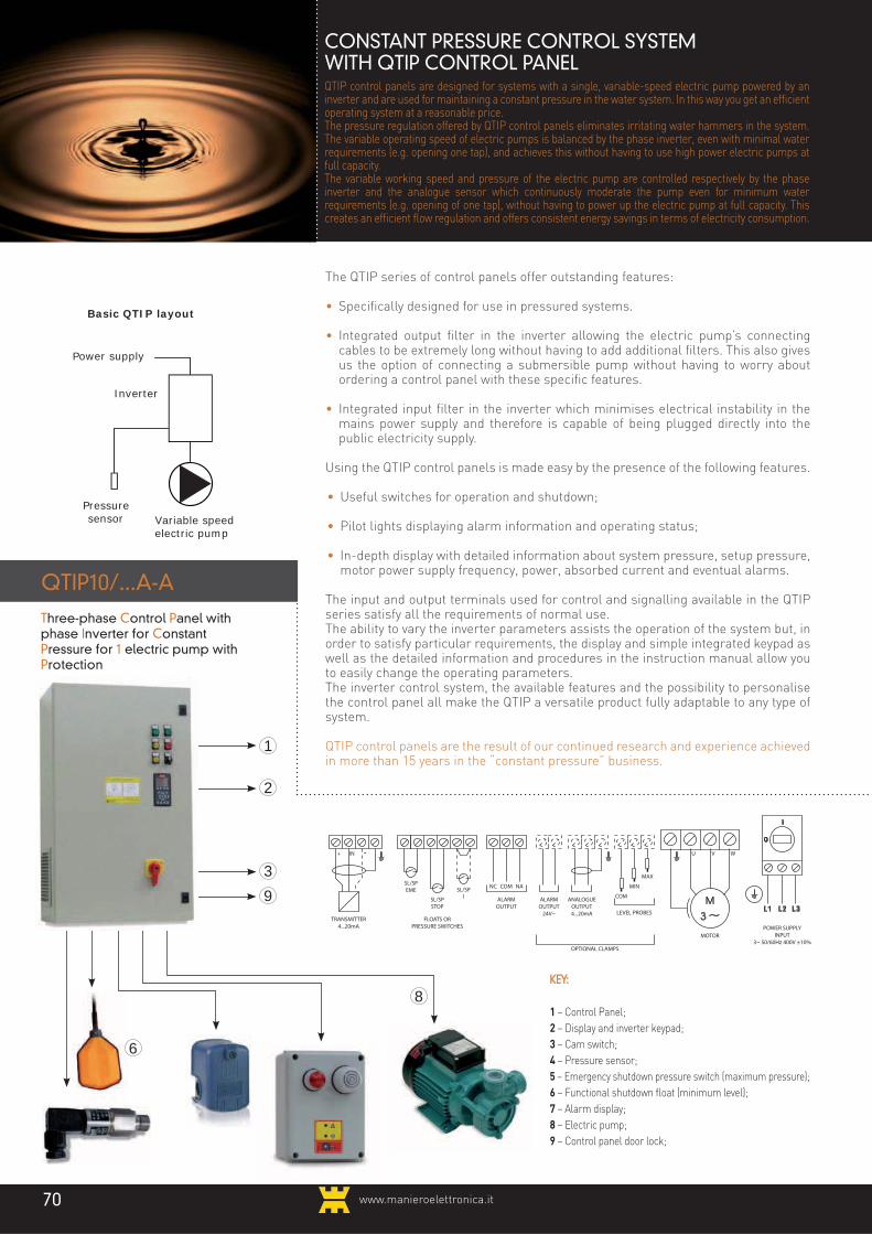
www.manieroelettronica.it70
KEY:
1 – Control Panel;
2 – Display and inverter keypad;
3 – Cam switch;
4 – Pressure sensor;
5 – Emergency shutdown pressure switch (maximum pressure);
6 – Functional shutdown float (minimum level);
7 – Alarm display;
8 – Electric pump;
9 – Control panel door lock;
Three-phase Control Panel with phase Inverter for Constant Pressure for 1 electric pump with Protection
8
FLOATS ORPRESSURE SWITCHES
OPTIONAL CLAMPS
TRANSMITTER4...20mA
SL/SPEME
+ -
ALARMOUTPUT
ANALOGUEOUTPUT4...20mA
U V W
LEVEL PROBES
ALARMOUTPUT
24V~
MOTORPOWER SUPPLY
INPUT3~ 50/60Hz 400V ±10%
NC COM
COM
MIN
MAX
NA
IN
SL/SPSTOP
SL/SP1
CONSTANT PRESSURE CONTROL SYSTEM WITH QTIP CONTROL PANELQTIP control panels are designed for systems with a single, variable-speed electric pump powered by an inverter and are used for maintaining a constant pressure in the water system. In this way you get an efficient operating system at a reasonable price. The pressure regulation offered by QTIP control panels eliminates irritating water hammers in the system. The variable operating speed of electric pumps is balanced by the phase inverter, even with minimal water requirements (e.g. opening one tap), and achieves this without having to use high power electric pumps at full capacity.The variable working speed and pressure of the electric pump are controlled respectively by the phase inverter and the analogue sensor which continuously moderate the pump even for minimum water requirements (e.g. opening of one tap), without having to power up the electric pump at full capacity. This creates an efficient flow regulation and offers consistent energy savings in terms of electricity consumption.
QTIP10/...A-A
2
3
1
The QTIP series of control panels offer outstanding features:
• Specifically designed for use in pressured systems.
• Integrated output filter in the inverter allowing the electric pump’s connecting cables to be extremely long without having to add additional filters. This also gives us the option of connecting a submersible pump without having to worry about ordering a control panel with these specific features.
• Integrated input filter in the inverter which minimises electrical instability in the mains power supply and therefore is capable of being plugged directly into the public electricity supply.
Using the QTIP control panels is made easy by the presence of the following features.
• Useful switches for operation and shutdown;
• Pilot lights displaying alarm information and operating status; • In-depth display with detailed information about system pressure, setup pressure,
motor power supply frequency, power, absorbed current and eventual alarms.
The input and output terminals used for control and signalling available in the QTIP series satisfy all the requirements of normal use.The ability to vary the inverter parameters assists the operation of the system but, in order to satisfy particular requirements, the display and simple integrated keypad as well as the detailed information and procedures in the instruction manual allow you to easily change the operating parameters.The inverter control system, the available features and the possibility to personalise the control panel all make the QTIP a versatile product fully adaptable to any type of system.
QTIP control panels are the result of our continued research and experience achieved in more than 15 years in the “constant pressure” business.
Inverter
Power supply
Variable speed electric pump
Basic QTIP layout
Pressuresensor
6
9

71www.manieroelettronica.it
USING THE QTIP
• The expansion vessel used to measure the precise pressure must be of around 5-15 litres, it must be pressurised to a pressure of around 30% below the system pressure and installed very close to the pressure transmitter.
• The security pressure switch installed on the water pipe is needed to guarantee that the system pressure, and also in case the inverter sensor malfunctions, does not exceed the maximum pressure sustainable by the water pipes.
In order to make the most of QTIP control panels it is necessary to satisfy the following conditions:• The electric pump must have the necessary
features to be powered by the inverter.• The maximum distance between the
control panel and surface electric pump must be within the limits stipulated in the technical features section.
• The maximum distance between the control panel and a submersible electric pump and other conditions must be first considered by our technical / sales office.
• The circuit breaker which protects the power supply against indirect contacts must be type “A” (for AC & DC currents) and protect against overload with the capability of selecting the threshold (300ma recommended) and the breaker time delay (0.5 seconds recommended).
• The pressure sensor is an analogue transmitter 2 wires 4...20ma e and must be installed away from the pump and preferably at the end of an elbow joint between 10 & 50cm long on the system pipes.
QTIP application layout
Electricitysupply
QTIPcontrol panel
Pressuresensor
“Maximumpressure”pressure
switch
Expansion vessel
Water system tank
“Minimal level” float
Variable speedelectric pump
Water outlet pipe

72www.manieroelettronica.it72
MODES OF USE
AUTOMATIC MODE:
The electric pump works at variable speeds between two preset values in order to maintain the system water pressure as constant as possible and equal to the preset nominal pressure which varies according to the flow-rate determined by water requirements.The instant pressure in the system is continuously measured by an analogue pressure sensor which transmits data to the control system.The control system is capable of automatically measuring, without any external control, the conditions of “shut-off pressure” and “zero flow” and consequently shuts down the electric pump.
In the case of “shut-off pressure”, before shutting down the electric pump, the pressure slightly exceeds the nominal preset pressure. The electric pump starts up again automatically once the pressure returns below a certain value with respect to the nominal preset pressure.In the case of “zero flow”, the electric pump attempts to restart at regular intervals and is able to do so only if the cause of the shutdown has disappeared.The gradual shutdown and eventual restart of the electric pump are not only determined by the control selector but also by the status of the SL/SP STOP device which could be a float to reveal the minimum level in the water system’s tank.The instant shutdown and restart of the electric pump are determined by the status of the device connected to the SL/SP EME input which could be for example a pressure switch revealing the maximum pressure allowed inside the system pipes.
MANUALE:
MANUAL MODE:
The electric pump works at a fixed speed preset by the user. The inverter does not reveal the conditions of “shut-off pressure” and “zero flow” hence the shutdown depends on the position of the control selector or on the devices connected to the inputs SL/SP STOP and SL/SP EME which, when open, respectively cause the gradual or instant shutdown of the electric pump.
Example of pressure regulationin AUTOMATIC mode
Shut down over-pressure System Pressure
Presetnominalpressure
Restartpressure
Time
Pumpspeed
Pump 1(working)
"Minimumlevel"input open
close
Pump shutdowndue to "dry-running"
Restart pumpfor "low pressure"
Shutdown and start-uppump by external command
Pressure
MODES OF USE
The control selector on the front control panel is used to start the system in AUTOMATIC mode, shutdown, or override the electric pump to OFF or MANUAL mode.

7373www.manieroelettronica.it
QTIP CONTROL PANEL FEATURES
TECHNICAL FEATURES AND APPLIED POWER
MODEL CODE MAXIMUM
CURRENT
(A)
SUGGESTED APPLICATIONS
Submersible
pump
(kW) to 400V
Surface pumps,
general motors
(kW) to 400V
WEIGHT
(kg)
DIMENSIONS
AHeight
(mm)
BWidth
(mm)
PDepth
(mm)
511.09
511.10
511.11
511.12
511.13
511.14
511.15
511.17
511.18
511.19
511.20
511.21
511.22
511.23
511.24
511.26
511.27
3
4,1
5,6
7,2
10
13
16
24
32
37,5
44
61
73
90
106
147
177
0,75
1,1
1,5
2,2
3
4
5,5
7,5
11
15
18,5
22
30
37
45
55
75
1,1
1,5
2,2
3
4
5,5
7,5
11
15
18,5
22
30
37
45
55
75
90
30
30
31
31
32
34
42
60
61
62
72
73
115
116
118
136
140
600
600
600
600
600
600
600
1000
1000
1000
1200
1200
1200
1200
1200
1200
1200
400
400
400
400
400
400
400
600
600
600
600
600
600
600
600
800
800
290
290
290
290
290
290
290
440
440
440
440
440
470
470
470
470
470
QTIP10/3A-A
QTIP10/4,1A-A
QTIP10/5,6A-A
QTIP10/7,2A-A
QTIP10/10A-A
QTIP10/13A-A
QTIP10/16A-A
QTIP10/24A-A
QTIP10/32A-A
QTIP10/37A-A
QTIP10/44A-A
QTIP10/61A-A
QTIP10/73A-A
QTIP10/90A-A
QTIP10/106A-A
QTIP10/147A-A
QTIP10/177A-A
• Electric pump or inverter protection alarm;− External panel with keypad and multi-language LCD graphical display for programming parameters, visualising alarms and real-time monitoring:
• Real system pressure;• Preset pressure; • Frequency, power and current absorbed by
the motor;
SYSTEM PARAMETERS
− Typical parameters in AUTOMATIC mode (constant pressure):
• Nominal system pressure;• Pressure sensor pressure; • Minimum and maximum motor frequency;• PI regulator (proportional gain and integral
time) in order to regulate the frequency generated by the inverter for the electric pump power supply;
• Enable shutdown for "shut-off pressure" (shuts off water);
• Minimum power to reveal the "shut-off pressure" or "zero flow";
• Restart pressure when flow returns (turns on water);
• Pause before trying to reset from “zero flow” shutdown;
- Typical parameters MANUAL mode (at constant speed);
• Output frequency generated by the inverter to power the electric pump;
ALARMS AND PROTECTIONS
− Pressure sensor broken or missing;− Electronic protection for over-current automatic limit of output and shutdown frequency;− Electronic protection for electric pump over-temperature with no PTC auxiliary sensor applied to the motor;− Electronic protection for inverter over- temperature;− Fuse protection for the inverter’s power supply and auxiliary circuits;
OPTIONAL FEATURES
− Ammeter to measure the absorbed current by the motor and inverter;− Voltmeter;− Voltmeter selector;− External control input for enabling operation in AUTOMATIC mode via N.C. contact or 24V~ voltage;− Alarm out a 24Vac;− Power supply output 24Vac;− Electric pump switch;− CLU/3S-24V control modules level probes;− MTG/P-1-96 daily timer for start-up and shutdown in AUTOMATIC or MANUAL mode;− Programming adapted to pressure systems for the following:
• Reference compensation based on the flow;
• Gradual filling of the tubes against water hammers;
• Warning for incorrect sizing of the pump in the water system
− Programming adapted for activities such as:• Emptying (control and maintenance of the
minimum level in a water basin);• Variable speed operation with control and
external control (control and maintenance of the operating motor at the desired speed);
− RS-485 Serial bus communication with MODBUS-RTU protocol;
SERVICE CONDITIONS
– Ambient temperature -5/+40°C;– Relative humidity 50% at a maximum temperature of 40°C.
GENERAL FEATURES:
− Three-phase control panel for one electric pump with phase inverter for the pressurisation of water systems and water treatment (emptying or other uses);− Three-phase power supply 3~ 50/60Hz 400V ± 10%;− Anti-interference RFI filter built in to the inverter for public mains supply (“civil use”);− Main isolator with door lock;− Induced air;− Metal cover;− IP54 protection.
MOTOR OUTPUTS
− Three-phase outputs from inverter for supplying variable speed electric pump;− Maximum motor cable length: 150m with core-screening, 300m without;− Break torque 110%.
CONTROL INPUTS & OUTPUTS
− Very low voltage input for transmitter of analogue pressure 2/3 wires 4...20ma POWER SUPPLY 24V (e.g. SPE3/...B- G¼m-5m);− 3 very low voltage inputs for:
• emergency shutdown (e.g. “maximum pressure” pressure switch);
• Functional shutdown (e.g. “minimal level0” float);
• external command start / stop with fixed speed inverter (e.g. regulation pressure switch).
− Output relays with exchange contacts N.O./N.C. for alarms 250V~ 5a max resistance).
COMMANDS AND SIGNALLING
− Electromechanical selector for AUTOMATIC — OFF — MANUAL;− 5 pilot lights to show:
• power supply;• emergency device intervention (e.g.
"maximum pressure” pressure switch);• Functional shutdown device (e.g. “minimal
level” float) or regulation shutdown (e.g. command pressure switch) or electronic protection against “zero flow”;
• Electric pump in operation;
Select the panel rated above the maximum current absorbed by the motor.

"We feel positive, look at our results"
QPC SERIES CONSTANT PRESSURE CONTROL
SYSTEM
www.manieroelettronica.it74

75www.manieroelettronica.it
4 ...
10
CPC SYSTEM - CONSTANT PRESSURE CONTROL WITH MICROPROCESSORThe QPC control panels are designed for systems with one or more electric pumps for the constant pressure regulation in a water system where there is a notable difference between the minimum and maximum water flow-rates. In this way you get an efficient operating system at a reasonable price.The pressure regulation offered by the QPC control panels eliminates or reduces irritating water hammers in the system.The variable working speed of the main electric pump using a phase inverter as well as the pressure measurement through the analogue sensor and the usage of numerous secondary fixed speed electric pumps (depending on flow rate) continuously moderates the pressure not only for minimum water requirements (e.g. opening of one tap) but also for more consistent usage. This creates an efficient flow regulation and offers a consistent energy saving in terms of electricity consumption.
QPC control panels offer optimal performance::
• Features designed for specific use in pressurised systems;
• Integrated output filter in the inverter allowing the variable speed electric pump’s connecting cables to be extremely long without having to add additional filters. This also gives us the option of connecting a submersible pump without having to worry about ordering a control panel with these specific features;
• Integrated input filter in the inverter which minimises electrical instability in the mains
power supply and therefore is capable of being plugged directly into the mains electricity supply.
Other than the regulation with the inverter and pressure measurement using the analogue sensor, the QPC control panels offer an alternative operation with independent control of the electric pumps via single pressure switches. This function is useful in case of inverter or pressure sensor malfunction because the immediate need to make the system work is resolved despite the failure.
QPC control panels with only one electric pump are similar to the QTIP control panels, but the essential difference is that instead of the inverter they are fitted with an electromechanical starter and are controlled by a pressure switch.
QPC control panels are the result of our continued research and experience achieved in more than 15 years in the “constant pressure” business.
KEY:1 – Control panel;
2 – Display and inverter keypad;
3 – Cam switch with door lock;
4 – Pressure sensor;
5 – Emergency shut-off pressure switch
(“maximum pressure”);
QPC.../...kW-AT
Costant Pressure Control Panelwith Thermal and Ammetric Protection
6 ... 7
9
2
1
3
Inverter
Power supply Starters
Electric pumps 1 = primary at variable speed 2, 3 = secondary at variable speed
Pressure sensor 1 2 3
8
Basic QPC design for 3 electric pumps
5
6 – Float functional shut-off (“minimum level”);
7 – Control pressure switch (“regulation pressure”);
8 – Alarm indicating device;
9 – Electric pumps;
10 – Control panel door lock.
CONNECTIONS LAYOUT(3 pump control panel example)
FLOATS OR PRESSURE SWITCH THERMISTORMOTORS
TRANSMITTER4...20mA
SL/SPEME
+ -
ALARMOUTPUT
U V W
MOTOR1
POWER IN
3~ 50/60Hz 400V ±10%
NC COM NA
IN
SL/SPSTOP
SL/SP1
U V W
MOTOR2
U V W
MOTOR3
SL/SP2
SL/SP3
PT1 PT2 PT3
OPTIONAL CLAMPS
ANALOGUEOUTPUT4...20mA LEVEL
PROBES
ALARMOUTPUT
24V~
COM
MIN
MAX

www.manieroelettronica.it76
MULTI-INVERTER VERSION
MULTI-INVERTER VERSION
This version of the QPC control panels has the greatest performance since it regulates the number of electric pumps working at once and their speed assuring an optimal pressure regulation, the total absence of water hammers and the minimal electricity consumption.This is obtained by adding an inverter to supply power to each individual electric pump at the same frequency of that of the main pump.In practice it is like having a unique pump continuously moderating the flow-rate based on the pressure regulation requirements of the water system.
The use of the QPC control panels is made easy by the presence of the following features on the front of the control panel:• Selectors for choosing the settings for the entire
system and every single electric pump;• Pilot lights which indicate the working and alarm
status;• Display which offers detailed information such
as the pressure in the water system, the preset pressure, data related to the variable motor speed, the frequency of the power supply, power, absorbed current and alarms.
The input and output terminals used for controlling and signalling available in the QPC series satisfy all the requirements of normal use.The ability to vary the inverter parameters assists the operation of the system but, in order to satisfy particular requirements, the display and simple integrated keypad as well as the detailed information and procedures in the instruction manual allow you to easily change operating parameters.The inverter control system, the available features and the possibility to personalise the control panel all make the QPC a versatile product completely adaptable to any type of system.
1 2 3
Inverter
Power supply
Electric pumps 1 = primary at variable speed 2, 3 = secondary at fixed speed
Pressure sensor
Basic QPC MULTI-INVERTER designper 3 electric pumps

77www.manieroelettronica.it
CONTROL AND REGULATION SYSTEM FOR"CONSTANT PRESSURE" WITH QPC CONTROLPANELS
In order to make the most of the QPC control panels it is necessary to satisfy the following conditions:
• The electric pump must have the necessary features to be powered by the inverter.
• The maximum distance between the control panel and surface electric pump must be within the limits stipulated in the technical features section.
• The maximum distance between the control panel and a submersible electric pump installed in a well and other conditions must be first considered by our technical / sales office.
• The circuit breaker which protects the power supply against indirect contacts must be of the type “A” (for AC & DC currents) and protect against overload with the capability of selecting the threshold (300ma recommended) and the breaker time delay (0.5 seconds recommended).
• The pressure sensor is an analogue transmitter 2 wires 4...20ma e and must be installed away from the pump and preferably at the end of an elbow joint between 10 & 50cm long on the system pipes.
• The expansion vessel used to measure the precise pressure must be of around 5-15 litres, it must be pressurised to a pressure of around 30% below the system pressure and installed very close to the pressure transmitter.
• The security pressure switch installed on the water pipe is needed to guarantee that the system pressure, and also in case the inverter sensor malfunctions, does not exceed the maximum pressure sustainable by the water pipes.
QPC designexample with 3 pumps
Electricitysupply
QPCcontrol panel
Pressuresensor
“Maximumpressure”pressure
switch
Expansion vessel
Water system tank
“Minimal level” float
Mainvariable speedelectric pump
Water outlet pipe
Secondaryfixed speed
electric pumps

www.manieroelettronica.it78
The control system is capable of automatically measuring, without any external control, the conditions of “shut-off pressure” and consequently shuts down the electric pump.In the case of “shut-off pressure”, before shutting down the electric pump, the pressure slightly exceeds the preset nominal pressure. The electric pump starts up again automatically once pressure returns below a certain value with respect to the preset nominal pressure.The gradual shutdown and eventual restart of the electric pump are not only determined by the control selector but also by the status of the SL/SP STOP device which could be a float to reveal the minimum level in the water system tank.The instant shutdown and restart of the electric pumps are determined by the status of the device connected to the SL/SP EME input which could be for example a pressure switch revealing the maximum pressure allowed inside the system pipes.
AUTOMATIC AT FIXED SPEED:
This is the mode of use which, in case of analogue or inverter failure, offers the possibility to keep the system running,
CONTROL SYSTEM AND REGULATION FOR"CONSTANT PRESSURE" WITH QPC CONTROLPANELS
MODES OF USE
The control selectors on the front of the control panel are used to start the system in AUTOMATIC mode, shutdown, or override the electric pump to OFF or MANUAL mode.The electromechanical selector feature on the front of the control panel, influences all of the electric pumps working in AUTOMATIC mode:• OFF: all the electric pumps are shut
down.• VARIABLE SPEED: the main electric
pump is at variable speed powered by the inverter, any secondary electric pumps are at fixed speed (*), the pressure is measured by an analogue sensor.
(*)NB: In the QPC MULTI-INVERTER control panels even the secondary pumps are at variable speed.
• FIXED SPEED: the main electric pump is at fixed speed powered by the inverter, any secondary electric pumps are fixed speed, pressure is measured via single pressure switches which independently control the individual pumps.
AUTOMATIC AT VARIABLE SPEED:
The QPC control panels are characterised by their modes of use where the main electric pump works at a variable speed between the minimum and maximum preset inverter values. This function maintains the internal water system pressure as constant as possible and equal to the preset nominal pressure value based on the flow-rate determined by the water requirements.The instant pressure in the system is continuously measured by an analogue pressure sensor which transmits data to the control system. The start-up of the secondary electric pumps occurs when those already working are insufficient and so the pressure value falls below that required.In much the same way, the shutdown of the secondary electric pumps occurs when those already working are excessive and so the pressure value rises above that required.The start-up and shut-down of the secondary electric pumps is carried out in such a way as to evenly distribute their running time as much as possible so that the working hours between the pumps is as equal as possible.
Time
Pressure
Example of pressure regulation with 3 pumps working AUTOMATICALLY - VARIABLE SPEED
Pump 1 (working)
System Pressure
Startsecondary pump
for low pressure
max
min
Pump 2 (working)
on
off
Pump 3 (working)
on
off
closed
open
"Minimumlevel"
in
Set hysteresis
Nominalpressure
Pumpspeed
off
Stop and startexternal command pump in sequence
Stopsecondary pump
due to high pressure
even if at reduced capacity.All the electric pumps work at fixed speed, including the main one powered by the inverter which works at the frequency preset by the user.The system does not measure the “shut-off pressure” condition and the regulation of the pressure in the system is entrusted exclusively to the control pressure switches connected to the inputs SL/SP 1-6 which control each individual electric pump.The security conditions are assigned to the devices connected to the SL/SP STOP and SL/SP EME which determine the simultaneous shutdown and allow all the electric pumps to work.
MANUAL:
Each single electric pump can be forced to work in the same way AUTOMATIC at FIXED SPEED, but without the influence of its own control pressure switch.Security conditions are assigned to the devices connected to the SL/SP STOP and SL/SP EME inputs which determine the simultaneous shutdown and allow all the electric pumps to work.

79www.manieroelettronica.it
− Secondary pump motor protection with
internally restorable thermal relay switch
− Fuse protection for the inverter’s power
supply;
− Fuse protection for the secondary pumps’
power supply;
− Fuse protection on auxiliary circuits;
OPTIONAL FEATURES
− Ammeters for motor and inverter absorbed
current measurement;
− Voltmeter;
− Voltmeter switch;
− External control input for enabling operation
in AUTOMATIC mode via N.C. contact or
24V~ voltage;
− 24Vac alarm output;
− Power supply output external auxiliary
24Vac;
− Electric pump switch;
− CLU/3S-24V control modules level probes;
− MTG/P-1-96 daily timer for start-up and
shutdown in AUTOMATIC or MANUAL mode;
− Programming adapted to pressure systems
for the following:
• Reference compensation based on the
flow;
• Gradual filling of the tubes against water
hammers;
• Warning for incorrect sizing of the pump
in the water system;
− RS-485 Serial bus communication with
MODBUS-RTU protocol;
SERVICE CONDITIONS
– Ambient temperature -5/+40°C;
– Relative humidity 50% at a maximum
temperature of 40°C.
QPC CONTROL PANEL FEATURES
in AUTOMATIC mode;
− N.1—6 electromechanical selectors for
AUTOMATIC — OFF— MANUAL modes;
− 5 pilot lights for indicating:
• Power supply;
• Emergency device intervention (e.g.
“maximum pressure” pressure switch;
• Functional arrest device (e.g. “minimal level”
float);
• VARIABLE SPEED mode;
• FIXED SPEED mode;
− 2 pilot lights for each electric pump indicating:
• Electric pump operating;
• Electric pump protection or inverter alarm
(only for main electric pump);
- External panel with keypad and multi-language
LCD graphical display for programming
parameters, visualising alarms and real-time
monitoring:
• Real system pressure;
• Preset pressure;
• Frequency, power and current absorbed by
the motor.
SETUP PARAMETERS
− Typical parameters in AUTOMATIC mode at
variable speed (constant pressure):
• Nominal system pressure;
• Pressure sensor pressure;
• Minimum and maximum motor frequency
of the main pump;
• PI regulator (proportional gain
and integral time) in order to regulate the
frequency generated by the inverter for the
electric pump power supply;
• Enable shutdown for "shut-off pressure"
(shuts off water);
• Minimum power to reveal the "shut-off
pressure";
• Restart pressure when flow returns (turns
on water);
− Typical parameters of MANUAL mode or
AUTOMATIC mode at FIXED SPEED (constant
speed) of the main electric pump:
• Output frequency generated by the inverter
to power the electric pump.
ALARMS AND PROTECTIONS
− Pressure sensor broken or missing;
− Electronic protection for inverter
over-temperature;
− Main pump motor protection with:
• Over-current monitoring and output and
shut-off frequency regulation;
• Over-temperature monitoring with no PTC
auxiliary sensors applied to the motor;
GENERAL FEATURES:
− Three-phase control panel for 1—6
electric pumps with a phase inverter for the
pressurisation of water systems;
− Three-phase power supply 3~ 50/60Hz 400V
± 10%;
− Anti-interference RFI filter built in to the
inverter for public mains supply (“civil use”);
− Main isolator with door lock;
− Induced air;
− Metal cover;
− IP54 protection;
MOTOR OUTPUTS
− Three-phase output from inverter for
supplying one variable speed electric pump;
− Maximum motor cable length: 150m with
core-screening, 300m without;
− Break torque 110%;
− Three-phase output from inverter for
powering from 1 to 5 secondary electric
pumps fixed speed with various types of start-
up (direct start, star-delta, “soft starter”)
based on the control panel model;
− Alternate start-up of the secondary electric
pumps;
− In the MULTI-INVERTER control panels there
is a maximum of 4 secondary electric pumps
which are each powered by their own inverter
at the same frequency as the main electric
pump;
CONTROL INPUTS & OUTPUTS
− Very low voltage input for the analogue
pressure transmitter 2/3 wires
4...20ma power supply 24V (e.g. SPE3/...B-
G¼m-5m);
− 2 very low voltage inputs for:
• emergency shutdown (e.g.: “maximum
pressure” pressure switch)
• functional shutdown (e.g. “minimum level”
float)
− 1—6 very low voltage inputs for electric pump
control pressure switches “automatic at fixed
speed”;
− 1—6 very low voltage inputs for N.C. contact
probe or thermistor for motor over-temperature
measurement;
− relay output 1 contact in exchange N.O. / N.C.
indicating alarms (250V~ 5a resistance load);
CONTROLS AND SIGNALLING− Electromechanical selector for
VARIABLE SPEED — OFF—
FIXED SPEED electric pumps modes enabled

QPC CONTROL PANEL FEATURES
QPC
www.manieroelettronica.it80
TECHNICAL FEATURES AND APPLIED POWERQPC10D/...kW-AT - Constant pressure control panel for 1 electric pump under ammetric protection inverter reserve with Direct start and thermal
protection.
MODEL CODE MAXIMUM
CURRENT
(A)
SUGGESTED APPLICATIONS
Submersible
pump
(kW) to 400V
Surface pumps,
general motors
(kW) to 400V
WEIGHT
(kg)
DIMENSIONS
AHeight
(mm)
BWidth
(mm)
PDepth
(mm)
QPC10D/3A-AT
QPC10D/4,1A-AT
QPC10D/5,6A-AT
QPC10D/7,2A-AT
QPC10D/10A-AT
QPC10D/13A-AT
QPC10D/16A-AT
QPC10D/24A-AT
QPC10D/32A-AT
QPC10D/37A-AT
QPC10D/44A-AT
QPC10D/61A-AT
QPC10D/73A-AT
QPC10D/90A-AT
QPC10D/106A-AT
QPC10D/147A-AT
500.09
500.10
500.11
500.12
500.13
500.14
500.15
500.17
500.18
500.19
500.20
500.21
500.22
500.23
500.24
500.26
3
4,1
5,6
7,2
10
13
16
24
32
37,5
44
61
73
90
106
147
0,75
1,1
1,5
2,2
3
4
5,5
7,5
11
15
18,5
22
30
37
45
55
1,1
1,5
2,2
3
4
5,5
7,5
11
15
18,5
22
30
37
45
55
75
32
32
32
32
32
57
57
80
82
83
90
90
137
137
210
210
800
800
800
800
800
800
800
1000
1000
1000
1000
1000
1200
1200
1400
1400
600
600
600
600
600
600
600
600
600
600
800
800
800
800
800
800
340
340
340
340
340
440
440
440
440
440
440
440
470
470
470
470
MODEL CODE MAXIMUM
CURRENT
(A)
SUGGESTED APPLICATIONS
Submersible
pump
(kW) to 400V
Surface pumps,
general motors
(kW) to 400V
WEIGHT
(kg)
DIMENSIONS
AHeight
(mm)
BWidth
(mm)
PDepth
(mm)
QPC20D/3A-AT
QPC20D/4,1A-AT
QPC20D/5,6A-AT
QPC20D/7,2A-AT
QPC20D/10A-AT
QPC20D/13A-AT
QPC20D/16A-AT
QPC20D/24A-AT
QPC20D/32A-AT
QPC20D/37A-AT
QPC20D/44A-AT
QPC20D/61A-AT
QPC20D/73A-AT
QPC20D/90A-AT
QPC20D/106A-AT
QPC20D/147A-AT
500.59
500.60
500.61
500.62
500.63
500.64
500.65
500.67
500.68
500.69
500.70
500.71
500.72
500.73
500.74
500.76
3
4,1
5,6
7,2
10
13
16
24
32
37,5
44
61
73
90
106
147
0,75
1,1
1,5
2,2
3
4
5,5
9
11
15
18,5
22
30
37
45
55
1,1
1,5
2,2
3
4
5,5
7,5
11
15
18,5
22
30
37
45
55
75
40
40
42
42
43
60
60
70
800
800
800
800
800
1000
1000
1000
600
600
600
600
600
600
600
800
340
340
340
340
340
340
340
340
TECHNICAL FEATURES AND APPLIED POWERQPC20D/...kW-AT -Constant pressure control panel for 2 electric pumps: 1 under inverter with ammetric protection
1 with Direct start with thermal protection
Select the panel rated above the maximum current absorbed by the motor.
Select the panel rated above the maximum current absorbed by the motor.

QPC CONTROL PANEL FEATURES
QPC
81www.manieroelettronica.it
MODEL CODE MAXIMUM
CURRENT
(A)
SUGGESTED APPLICATIONS
Submersible
pump
(kW) to 400V
Surface pumps,
general motors
(kW) to 400V
WEIGHT
(kg)
DIMENSIONS
AHeight
(mm)
BWidth
(mm)
PDepth
(mm)
QPC30D/3A-AT
QPC30D/4,1A-AT
QPC30D/5,6A-AT
QPC30D/7,2A-AT
QPC30D/10A-AT
QPC30D/13A-AT
QPC30D/16A-AT
QPC30D/24A-AT
QPC30D/32A-AT
QPC30D/37A-AT
QPC30D/44A-AT
QPC30D/61A-AT
QPC30D/73A-AT
QPC30D/90A-AT
QPC30D/106A-AT
QPC30D/147A-AT
501.09
501.10
501.11
501.12
501.13
501.14
501.15
501.17
501.18
501.19
501.20
501.21
501.22
501.23
501.24
501.26
3
4,1
5,6
7,2
10
13
16
24
32
37,5
44
61
73
90
106
147
0,75
1,1
1,5
2,2
3
4
5,5
9
11
15
18,5
22
30
37
45
55
1,1
1,5
2,2
3
4
5,5
7,5
11
15
18,5
22
30
37
45
55
75
54
54
57
57
58
72
72
82
1000
1000
1000
1000
1000
1000
1000
1200
600
600
600
600
600
600
800
800
340
340
340
340
340
340
340
370
MODEL CODE MAXIMUM
CURRENT
(A)
SUGGESTED APPLICATIONS
Submersible
pump
(kW) to 400V
Surface pumps,
general motors
(kW) to 400V
WEIGHT
(kg)
DIMENSIONS
AHeight
(mm)
BWidth
(mm)
PDepth
(mm)
QPC40D/3A-AT
QPC40D/4,1A-AT
QPC40D/5,6A-AT
QPC40D/7,2A-AT
QPC40D/10A-AT
QPC40D/13A-AT
QPC40D/16A-AT
QPC40D/24A-AT
QPC40D/32A-AT
QPC40D/37A-AT
QPC40D/44A-AT
QPC40D/61A-AT
QPC40D/73A-AT
QPC40D/90A-AT
QPC40D/106A-AT
QPC40D/147A-AT
501.59
501.60
501.61
501.62
501.63
501.64
501.65
501.67
501.68
501.69
501.70
501.71
501.72
501.73
501.74
501.76
3
4,1
5,6
7,2
10
13
16
24
32
37,5
44
61
73
90
106
147
0,75
1,1
1,5
2,2
3
4
5,5
9
11
15
18,5
22
30
37
45
55
1,1
1,5
2,2
3
4
5,5
7,5
11
15
18,5
22
30
37
45
55
75
64
64
66
66
74
74
140
1000
1000
1000
1000
1000
1000
2000
800
800
800
800
800
800
1000
340
340
340
340
340
340
500
TECHNICAL FEATURES AND APPLIED POWERQPC30D/...kW-AT - Constant pressure control panel for 3 electric pumps: 1 under inverter with ammetric protection
2 with Direct start with thermal protection
TECHNICAL FEATURES AND APPLIED POWERQPC40D/...kW-AT - Constant pressure control panel for 4 electric pumps: 1 under inverter with ammetric protection
3 with Direct start with thermal protection
Select the panel rated above the maximum current absorbed by the motor.
Select the panel rated above the maximum current absorbed by the motor.

QPC CONTROL PANEL FEATURES
QPC
www.manieroelettronica.it82
QPC50D/3A-AT
QPC50D/4,1A-AT
QPC50D/5,6A-AT
QPC50D/7,2A-AT
QPC50D/10A-AT
QPC50D/13A-AT
QPC50D/16A-AT
QPC50D/24A-AT
QPC50D/32A-AT
QPC50D/37A-AT
QPC50D/44A-AT
QPC50D/61A-AT
QPC50D/73A-AT
QPC50D/90A-AT
QPC50D/106A-AT
QPC50D/147A-AT
502.09
502.10
502.11
502.12
502.13
502.14
502.15
502.17
502.18
502.19
502.20
502.21
502.22
502.23
502.24
502.26
3
4,1
5,6
7,2
10
13
16
24
32
37,5
44
61
73
90
106
147
0,75
1,1
1,5
2,2
3
4
5,5
9
11
15
18,5
22
30
37
45
55
1,1
1,5
2,2
3
4
5,5
7,5
11
15
18,5
22
30
37
45
55
75
QPC60D/3A-AT
QPC60D/4,1A-AT
QPC60D/5,6A-AT
QPC60D/7,2A-AT
QPC60D/10A-AT
QPC60D/13A-AT
QPC60D/16A-AT
QPC60D/24A-AT
QPC60D/32A-AT
QPC60D/37A-AT
QPC60D/44A-AT
QPC60D/61A-AT
QPC60D/73A-AT
QPC60D/90A-AT
QPC60D/106A-AT
QPC60D/147A-AT
502.59
502.60
502.61
502.62
502.63
502.64
502.65
502.67
502.68
502.69
502.70
502.71
502.72
502.73
502.74
502.76
3
4,1
5,6
7,2
10
13
16
24
32
37,5
44
61
73
90
106
147
1,1
1,5
2,2
3
4
5,5
7,5
11
15
18,5
22
30
37
45
55
75
1,1
1,5
2,2
3
4
5,5
7,5
11
15
18,5
22
30
37
45
55
75
TECHNICAL FEATURES AND APPLIED POWERQPC50D/...kW-AT - Constant pressure control panel for 5 electric pumps: 1 under inverter with ammetric protection
4 with Direct start with thermal protection
TECHNICAL FEATURES AND APPLIED POWERQPC60D/...kW-AT - Constant pressure control panel for 6 electric pumps: 1 under inverter with ammetric protection
5 with Direct start with thermal protection
MODEL CODE MAXIMUM
CURRENT
(A)
SUGGESTED APPLICATIONS
Submersible
pump
(kW) to 400V
Surface pumps,
general motors
(kW) to 400V
WEIGHT
(kg)
DIMENSIONS
AHeight
(mm)
BWidth
(mm)
PDepth
(mm)
MODEL CODE MAXIMUM
CURRENT
(A)
SUGGESTED APPLICATIONS
Submersible
pump
(kW) to 400V
Surface pumps,
general motors
(kW) to 400V
WEIGHT
(kg)
DIMENSIONS
AHeight
(mm)
BWidth
(mm)
PDepth
(mm)
Select the panel rated above the maximum current absorbed by the motor.
Select the panel rated above the maximum current absorbed by the motor.

QPC CONTROL PANEL FEATURES
QPC
83www.manieroelettronica.it
QPC10ST/7,2A-AT
QPC10ST/10A-AT
QPC10ST/13A-AT
QPC10ST/16A-AT
QPC10ST/24A-AT
QPC10ST/32A-AT
QPC10ST/37A-AT
QPC10ST/44A-AT
QPC10ST/61A-AT
QPC10ST/73A-AT
QPC10ST/90A-AT
QPC10ST/106A-AT
QPC10ST/147A-AT
QPC10ST/177A-AT
QPC10ST/212A-AT
503.12
503.13
503.14
503.15
503.17
503.18
503.19
503.20
503.21
503.22
503.23
503.24
503.26
503.27
503.28
7,2
10
13
16
24
32
37,5
44
61
73
90
106
147
177
212
2,2
3
4
5,5
7,5
11
15
18,5
22
30
37
45
55
75
90
3
4
5,5
7,5
11
15
18,5
22
30
37
45
55
75
90
110
QPC20ST/7,2A-AT
QPC20ST/10A-AT
QPC20ST/13A-AT
QPC20ST/16A-AT
QPC20ST/24A-AT
QPC20ST/32A-AT
QPC20ST/37A-AT
QPC20ST/44A-AT
QPC20ST/61A-AT
QPC20ST/73A-AT
QPC20ST/90A-AT
QPC20ST/106A-AT
QPC20ST/147A-AT
QPC20ST/177A-AT
QPC20ST/212A-AT
503.62
503.63
503.64
503.65
503.67
503.68
503.69
503.70
503.71
503.72
503.73
503.74
503.76
503.77
503.78
7,2
10
13
16
24
32
37,5
44
61
73
90
106
147
177
212
2,2
3
4
5,5
7,5
11
15
18,5
22
30
37
45
55
75
90
3
4
5,5
7,5
11
15
18,5
22
30
37
45
55
75
90
110
1000
1000
1000
1000
1200
1200
1400
1400
1400
1800
600
600
800
800
800
800
800
800
800
800
340
340
340
340
370
370
470
470
470
570
58
60
71
71
108
108
130
138
143
TECHNICAL FEATURES AND APPLIED POWERQPC10ST/...kW-AT - Constant pressure control panel for 3 electric pump under ammetric protection inverter and reserve Star-Delta start with thermal
protection
TECHNICAL FEATURES AND APPLIED POWERQPC20ST/...kW-AT - Constant pressure control panel for 2 electric pumps: 1 under inverter with ammetric protection
1 with reserve Star-Delta start with thermal protection
MODEL CODE MAXIMUM
CURRENT
(A)
SUGGESTED APPLICATIONS
Submersible
pump
(kW) to 400V
Surface pumps,
general motors
(kW) to 400V
WEIGHT
(kg)
DIMENSIONS
AHeight
(mm)
BWidth
(mm)
PDepth
(mm)
MODEL CODE MAXIMUM
CURRENT
(A)
SUGGESTED APPLICATIONS
Submersible
pump
(kW) to 400V
Surface pumps,
general motors
(kW) to 400V
WEIGHT
(kg)
DIMENSIONS
AHeight
(mm)
BWidth
(mm)
PDepth
(mm)
60
62
73
73
110
110
122
132
140
147
1000
1000
1000
1000
1200
1200
1400
1400
1400
1800
600
600
800
800
800
800
800
800
800
800
340
340
340
340
370
370
470
470
470
570
Select the panel rated above the maximum current absorbed by the motor.
Select the panel rated above the maximum current absorbed by the motor.

QPC CONTROL PANEL FEATURES
QPC
www.manieroelettronica.it84
QPC30ST/7,2A-AT
QPC30ST/10A-AT
QPC30ST/13A-AT
QPC30ST/16A-AT
QPC30ST/24A-AT
QPC30ST/32A-AT
QPC30ST/37A-AT
QPC30ST/44A-AT
QPC30ST/61A-AT
QPC30ST/73A-AT
QPC30ST/90A-AT
QPC30ST/106A-AT
QPC30ST/147A-AT
QPC30ST/177A-AT
QPC30ST/212A-AT
504.12
504.13
504.14
504.15
504.17
504.18
504.19
504.20
504.21
504.22
504.23
504.24
504.26
504.27
504.28
7,2
10
13
16
24
32
37,5
44
61
73
90
106
147
177
212
2,2
3
4
5,5
7,5
11
15
18,5
22
30
37
45
55
75
90
3
4
5,5
7,5
11
15
18,5
22
30
37
45
55
75
90
110
1000
1000
1000
1000
1200
1200
1400
1800
1800
2000
2000
800
800
800
800
800
800
800
800
800
800
1200
340
340
340
340
370
370
470
570
570
570
670
66
67
75
75
112
112
112
131
131
141
180
QPC40ST/7,2A-AT
QPC40ST/10A-AT
QPC40ST/13A-AT
QPC40ST/16A-AT
QPC40ST/24A-AT
QPC40ST/32A-AT
QPC40ST/37A-AT
QPC40ST/44A-AT
QPC40ST/61A-AT
QPC40ST/73A-AT
QPC40ST/90A-AT
QPC40ST/106A-AT
QPC40ST/147A-AT
QPC40ST/177A-AT
QPC40ST/212A-AT
504.62
504.63
504.64
504.65
504.67
504.68
504.69
504.70
504.71
504.72
504.73
504.74
504.76
504.77
50478
7,2
10
13
16
24
32
37,5
44
61
73
90
106
147
177
212
2,2
3
4
5,5
7,5
11
15
18,5
22
30
37
45
55
75
90
3
4
5,5
7,5
11
15
18,5
22
30
37
45
55
75
90
110
1200
1200
1200
1200
1400
1400
1600
1600
1600
800
800
800
800
800
800
800
800
800
440
440
440
440
470
470
470
470
470
90
92
101
101
129
129
156
157
158
TECHNICAL FEATURES AND APPLIED POWERQPC30ST/...kW-AT - Constant pressure control panel for 3 electric pumps: 1 under inverter with ammetric protection
2 with reserve Star-Delta start with thermal protection
TECHNICAL FEATURES AND APPLIED POWERQPC40ST/...kW-AT - Constant pressure control panel for 4 electric pumps: 1 under inverter with ammetric protection
3 with reserve Star-Delta start with thermal protection
MODEL CODE MAXIMUM
CURRENT
(A)
SUGGESTED APPLICATIONS
Submersible
pump
(kW) to 400V
Surface pumps,
general motors
(kW) to 400V
WEIGHT
(kg)
DIMENSIONS
AHeight
(mm)
BWidth
(mm)
PDepth
(mm)
MODEL CODE MAXIMUM
CURRENT
(A)
SUGGESTED APPLICATIONS
Submersible
pump
(kW) to 400V
Surface pumps,
general motors
(kW) to 400V
WEIGHT
(kg)
DIMENSIONS
AHeight
(mm)
BWidth
(mm)
PDepth
(mm)
Select the panel rated above the maximum current absorbed by the motor.
Select the panel rated above the maximum current absorbed by the motor.

QPC CONTROL PANEL FEATURES
QPC
85www.manieroelettronica.it
QPC50ST/7,2A-AT
QPC50ST/10A-AT
QPC50ST/13A-AT
QPC50ST/16A-AT
QPC50ST/24A-AT
QPC50ST/32A-AT
QPC50ST/37A-AT
QPC50ST/44A-AT
QPC50ST/61A-AT
QPC50ST/73A-AT
QPC50ST/90A-AT
QPC50ST/106A-AT
QPC50ST/147A-AT
QPC50ST/177A-AT
QPC50ST/212A-AT
505.12
505.13
505.14
505.15
505.17
505.18
505.19
505.20
505.21
505.22
505.23
505.24
505.26
505.27
505.28
7,2
10
13
16
24
32
37,5
44
61
73
90
106
147
177
212
2,2
3
4
5,5
7,5
11
15
18,5
22
30
37
45
55
75
90
3
4
5,5
7,5
11
15
18,5
22
30
37
45
55
75
90
110
QPC60ST/7,2A-AT
QPC60ST/10A-AT
QPC60ST/13A-AT
QPC60ST/16A-AT
QPC60ST/24A-AT
QPC60ST/32A-AT
QPC60ST/37A-AT
QPC60ST/44A-AT
QPC60ST/61A-AT
QPC60ST/73A-AT
QPC60ST/90A-AT
QPC60ST/106A-AT
QPC60ST/147A-AT
QPC60ST/177A-AT
QPC60ST/212A-AT
505.62
505.63
505.64
505.65
505.67
505.68
505.69
505.70
505.71
505.72
505.73
505.74
505.76
505.77
505.78
7,2
10
13
16
24
32
37,5
44
61
73
90
106
147
177
212
2,2
3
4
5,5
7,5
11
15
18,5
22
30
37
45
55
75
90
3
4
5,5
7,5
11
15
18,5
22
30
37
45
55
75
90
110
TECHNICAL FEATURES AND APPLIED POWERQPC50ST/...kW-AT - Constant pressure control panel for 5 electric pumps: 1 under inverter with ammetric protection
4 with reserve Star-Delta start with thermal protection
TECHNICAL FEATURES AND APPLIED POWERQPC60ST/...kW-AT - Constant pressure control panel for 6 electric pumps: 1 under inverter with ammetric protection
5 with reserve Star-Delta start with thermal protection
MODEL CODE MAXIMUM
CURRENT
(A)
SUGGESTED APPLICATIONS
Submersible
pump
(kW) to 400V
Surface pumps,
general motors
(kW) to 400V
WEIGHT
(kg)
DIMENSIONS
AHeight
(mm)
BWidth
(mm)
PDepth
(mm)
MODEL CODE MAXIMUM
CURRENT
(A)
SUGGESTED APPLICATIONS
Submersible
pump
(kW) to 400V
Surface pumps,
general motors
(kW) to 400V
WEIGHT
(kg)
DIMENSIONS
AHeight
(mm)
BWidth
(mm)
PDepth
(mm)
Select the panel rated above the maximum current absorbed by the motor.
Select the panel rated above the maximum current absorbed by the motor.

QPC CONTROL PANEL FEATURES
QPC
www.manieroelettronica.it86
QPC10SS/3A-AT
QPC10SS/4,1A-AT
QPC10SS/5,6A-AT
QPC10SS/7,2A-AT
QPC10SS/10A-AT
QPC10SS/13A-AT
QPC10SS/16A-AT
QPC10SS/24A-AT
QPC10SS/32A-AT
QPC10SS/37A-AT
QPC10SS/44A-AT
QPC10SS/61A-AT
QPC10SS/73A-AT
QPC10SS/90A-AT
QPC10SS/106A-AT
QPC10SS/147A-AT
QPC10SS/177A-AT
506.09
506.10
506.11
506.12
506.13
506.14
506.15
506.17
506.18
506.19
506.20
506.21
506.22
506.23
506.24
506.26
506.27
3
4,1
5,6
7,2
10
13
16
24
32
37,5
44
61
73
90
106
147
177
0,75
1,1
1,5
2,2
3
4
5,5
7,5
11
15
18,5
22
30
37
45
55
75
1,1
1,5
2,2
3
4
5,5
7,5
11
15
18,5
22
30
37
45
55
75
90
1200
1200
1400
800
800
800
470
470
470
120
120
150
QPC20SS/3A-AT
QPC20SS/4,1A-AT
QPC20SS/5,6A-AT
QPC20SS/7,2A-AT
QPC20SS/10A-AT
QPC20SS/13A-AT
QPC20SS/16A-AT
QPC20SS/24A-AT
QPC20SS/32A-AT
QPC20SS/37A-AT
QPC20SS/44A-AT
QPC20SS/61A-AT
QPC20SS/73A-AT
QPC20SS/90A-AT
QPC20SS/106A-AT
QPC20SS/147A-AT
QPC20SS/177A-AT
506.59
506.60
506.61
506.62
506.63
506.64
506.65
506.67
506.68
506.69
506.70
506.71
506.72
506.73
506.74
506.76
506.77
3
4,1
5,6
7,2
10
13
16
24
32
37,5
44
61
73
90
106
147
177
0,75
1,1
1,5
2,2
3
4
5,5
7,5
11
15
18,5
22
30
37
45
55
75
1,1
1,5
2,2
3
4
5,5
7,5
11
15
18,5
22
30
37
45
55
75
90
63
63
64
76
76
119
119
119
141
141
192
1000
1000
1000
1000
1000
1200
1200
1200
1400
1400
1600
600
600
600
800
800
800
800
800
800
800
800
340
340
340
340
340
440
470
470
470
470
570
TECHNICAL FEATURES AND APPLIED POWERQPC10SS/...kW-AT - Constant pressure control panel for 1 electric pump under ammetric protection inverter and reserve Soft-Start with thermal
protection
TECHNICAL FEATURES AND APPLIED POWERQPC20SS/...kW-AT - Constant pressure control panel for 2 electric pumps: 1 under inverter with ammetric protection
1 with Soft-Start with thermal protection
MODEL CODE MAXIMUM
CURRENT
(A)
SUGGESTED APPLICATIONS
Submersible
pump
(kW) to 400V
Surface pumps,
general motors
(kW) to 400V
WEIGHT
(kg)
DIMENSIONS
AHeight
(mm)
BWidth
(mm)
PDepth
(mm)
MODEL CODE MAXIMUM
CURRENT
(A)
SUGGESTED APPLICATIONS
Submersible
pump
(kW) to 400V
Surface pumps,
general motors
(kW) to 400V
WEIGHT
(kg)
DIMENSIONS
AHeight
(mm)
BWidth
(mm)
PDepth
(mm)
Select the panel rated above the maximum current absorbed by the motor.
Select the panel rated above the maximum current absorbed by the motor.

QPC CONTROL PANEL FEATURES
QPC
87www.manieroelettronica.it
QPC30SS/3A-AT
QPC30SS/4,1A-AT
QPC30SS/5,6A-AT
QPC30SS/7,2A-AT
QPC30SS/10A-AT
QPC30SS/13A-AT
QPC30SS/16A-AT
QPC30SS/24A-AT
QPC30SS/32A-AT
QPC30SS/37A-AT
QPC30SS/44A-AT
QPC30SS/61A-AT
QPC30SS/73A-AT
QPC30SS/90A-AT
QPC30SS/106A-AT
QPC30SS/147A-AT
QPC30SS/177A-AT
507.09
507.10
507.11
507.12
507.13
507.14
507.15
507.17
507.18
507.19
507.20
507.21
507.22
507.23
507.24
507.26
507.27
3
4,1
5,6
7,2
10
13
16
24
32
37,5
44
61
73
90
106
147
177
0,75
1,1
1,5
2,2
3
4
5,5
7,5
11
15
18,5
22
30
37
45
55
75
1,1
1,5
2,2
3
4
5,5
7,5
11
15
18,5
22
30
37
45
55
75
90
74
74
76
84
84
127
127
163
163
163
206
1000
1000
1000
1000
1000
1200
1200
1200
1600
1600
1600
800
800
800
800
800
800
800
800
800
800
800
340
340
340
340
340
470
470
570
570
570
570
QPC40SS/3A-AT
QPC40SS/4,1A-AT
QPC40SS/5,6A-AT
QPC40SS/7,2A-AT
QPC40SS/10A-AT
QPC40SS/13A-AT
QPC40SS/16A-AT
QPC40SS/24A-AT
QPC40SS/32A-AT
QPC40SS/37A-AT
QPC40SS/44A-AT
QPC40SS/61A-AT
QPC40SS/73A-AT
QPC40SS/90A-AT
QPC40SS/106A-AT
QPC40SS/147A-AT
QPC40SS/177A-AT
507.59
507.60
507.61
507.62
507.63
507.64
507.65
507.67
507.68
507.69
507.70
507.71
507.72
507.73
507.74
507.76
507.77
3
4,1
5,6
7,2
10
13
16
24
32
37,5
44
61
73
90
106
147
177
0,75
1,1
1,5
2,2
3
4
5,5
7,5
11
15
18,5
22
30
37
45
55
75
1,1
1,5
2,2
3
4
5,5
7,5
11
15
18,5
22
30
37
45
55
75
90
78
78
79
115
115
136
136
168
168
168
1000
1000
1000
1200
1200
1400
1400
1600
1600
1600
800
800
800
800
800
800
800
800
800
800
340
340
340
440
440
470
470
570
570
570
TECHNICAL FEATURES AND APPLIED POWERQPC30SS/...kW-AT - Constant pressure control panel for 3 electric pumps: 1 under inverter with ammetric protection
2 with Soft-Start with thermal protection
TECHNICAL FEATURES AND APPLIED POWERQPC40SS/...kW-AT - Constant pressure control panel for 4 electric pumps: 1 under inverter with ammetric protection
3 with Soft-Start with thermal protection
MODEL CODE MAXIMUM
CURRENT
(A)
SUGGESTED APPLICATIONS
Submersible
pump
(kW) to 400V
Surface pumps,
general motors
(kW) to 400V
WEIGHT
(kg)
DIMENSIONS
AHeight
(mm)
BWidth
(mm)
PDepth
(mm)
MODEL CODE MAXIMUM
CURRENT
(A)
SUGGESTED APPLICATIONS
Submersible
pump
(kW) to 400V
Surface pumps,
general motors
(kW) to 400V
WEIGHT
(kg)
DIMENSIONS
AHeight
(mm)
BWidth
(mm)
PDepth
(mm)
Select the panel rated above the maximum current absorbed by the motor.
Select the panel rated above the maximum current absorbed by the motor.

QPC CONTROL PANEL FEATURES
QPC
www.manieroelettronica.it88
QPC60SS/3A-AT
QPC60SS/4,1A-AT
QPC60SS/5,6A-AT
QPC60SS/7,2A-AT
QPC60SS/10A-AT
QPC60SS/13A-AT
QPC60SS/16A-AT
QPC60SS/24A-AT
QPC60SS/32A-AT
QPC60SS/37A-AT
QPC60SS/44A-AT
QPC60SS/61A-AT
QPC60SS/73A-AT
QPC60SS/90A-AT
QPC60SS/106A-AT
QPC60SS/147A-AT
QPC60SS/177A-AT
508.59
508.60
508.61
508.62
508.63
508.64
508.65
508.67
508.68
508.69
508.70
508.71
508.72
508.73
508.74
508.76
508.77
3
4,1
5,6
7,2
10
13
16
24
32
37,5
44
61
73
90
106
147
177
0,75
1,1
1,5
2,2
3
4
5,5
7,5
11
15
18,5
22
30
37
45
55
75
1,1
1,5
2,2
3
4
5,5
7,5
11
15
18,5
22
30
37
45
55
75
90
104
104
108
129
129
162
162
1200
1200
1200
1400
1400
1600
1600
800
800
800
800
800
800
800
340
340
340
470
470
570
570
QPC50SS/3A-AT
QPC50SS/4,1A-AT
QPC50SS/5,6A-AT
QPC50SS/7,2A-AT
QPC50SS/10A-AT
QPC50SS/13A-AT
QPC50SS/16A-AT
QPC50SS/24A-AT
QPC50SS/32A-AT
QPC50SS/37A-AT
QPC50SS/44A-AT
QPC50SS/61A-AT
QPC50SS/73A-AT
QPC50SS/90A-AT
QPC50SS/106A-AT
QPC50SS/147A-AT
QPC50SS/177A-AT
508.09
508.10
508.11
508.12
508.13
508.14
508.15
508.17
508.18
508.19
508.20
508.21
508.22
508.23
508.24
508.26
508.27
3
4,1
5,6
7,2
10
13
16
24
32
37,5
44
61
73
90
106
147
177
0,75
1,1
1,5
2,2
3
4
5,5
7,5
11
15
18,5
22
30
37
45
55
75
1,1
1,5
2,2
3
4
5,5
7,5
11
15
18,5
22
30
37
45
55
75
90
1400 800 440
TECHNICAL FEATURES AND APPLIED POWERQPC50SS/...kW-AT - Constant pressure control panel for 5 electric pumps: 1 under inverter with ammetric protection
4 with Soft-Start with thermal protection
TECHNICAL FEATURES AND APPLIED POWERQPC60SS/...kW-AT - Constant pressure control panel for 6 electric pumps: 1 under inverter with ammetric protection
5 with Soft-Start with thermal protection
MODEL CODE MAXIMUM
CURRENT
(A)
SUGGESTED APPLICATIONS
Submersible
pump
(kW) to 400V
Surface pumps,
general motors
(kW) to 400V
WEIGHT
(kg)
DIMENSIONS
AHeight
(mm)
BWidth
(mm)
PDepth
(mm)
MODEL CODE MAXIMUM
CURRENT
(A)
SUGGESTED APPLICATIONS
Submersible
pump
(kW) to 400V
Surface pumps,
general motors
(kW) to 400V
WEIGHT
(kg)
DIMENSIONS
AHeight
(mm)
BWidth
(mm)
PDepth
(mm)
Select the panel rated above the maximum current absorbed by the motor.
Select the panel rated above the maximum current absorbed by the motor.

QPC CONTROL PANEL FEATURES
QPC
89www.manieroelettronica.it
QPC20MI/3A-A
QPC20MI/4,1A-A
QPC20MI/5,6A-A
QPC20MI/7,2A-A
QPC20MI/10A-A
QPC20MI/13A-A
QPC20MI/16A-A
QPC20MI/24A-A
QPC20MI/32A-A
QPC20MI/37A-A
QPC20MI/44A-A
QPC20MI/61A-A
QPC20MI/73A-A
QPC20MI/90A-A
QPC20MI/106A-A
QPC20MI/147A-A
QPC20MI/177A-A
509.09
509.10
509.11
509.12
509.13
509.14
509.15
509.17
509.18
509.19
509.20
509.21
509.22
509.23
509.24
509.26
509.27
3
4,1
5,6
7,2
10
13
16
24
32
37,5
44
61
73
90
106
147
177
0,75
1,1
1,5
2,2
3
4
5,5
7,5
11
15
18,5
22
30
37
45
55
75
1,1
1,5
2,2
3
4
5,5
7,5
11
15
18,5
22
30
37
45
55
75
90
QPC30MI/3A-A
QPC30MI/4,1A-A
QPC30MI/5,6A-A
QPC30MI/7,2A-A
QPC30MI/10A-A
QPC30MI/13A-A
QPC30MI/16A-A
QPC30MI/24A-A
QPC30MI/32A-A
QPC30MI/37A-A
QPC30MI/44A-A
QPC30MI/61A-A
QPC30MI/73A-A
QPC30MI/90A-A
QPC30MI/106A-A
QPC30MI/147A-A
QPC30MI/177A-A
509.59
509.60
509.61
509.62
509.63
509.64
509.65
509.67
509.68
509.69
509.70
509.71
509.72
509.73
509.74
509.76
509.77
3
4,1
5,6
7,2
10
13
16
24
32
37,5
44
61
73
90
106
147
177
0,75
1,1
1,5
2,2
3
4
5,5
7,5
11
15
18,5
22
30
37
45
55
75
1,1
1,5
2,2
3
4
5,5
7,5
11
15
18,5
22
30
37
45
55
75
90
TECHNICAL FEATURES AND APPLIED POWERQPC20MI/...A-A - Constant pressure control panel for 2 electric pumps under inverter and ammetric protection IIIIIIIIIIIIIIIIIIIIIIIIIIIIIIIIIII
TECHNICAL FEATURES AND APPLIED POWER
QPC30MI/...A-A - Constant pressure control panel for 3 electric pumps under inverter and ammetric protection IIIIIIIIIIIIIIIIIIIIIIIIIIIIIIIIIII
MODEL CODE MAXIMUM
CURRENT
(A)
SUGGESTED APPLICATIONS
Submersible
pump
(kW) to 400V
Surface pumps,
general motors
(kW) to 400V
WEIGHT
(kg)
DIMENSIONS
AHeight
(mm)
BWidth
(mm)
PDepth
(mm)
MODEL CODE MAXIMUM
CURRENT
(A)
SUGGESTED APPLICATIONS
Submersible
pump
(kW) to 400V
Surface pumps,
general motors
(kW) to 400V
WEIGHT
(kg)
DIMENSIONS
AHeight
(mm)
BWidth
(mm)
PDepth
(mm)
Select the panel rated above the maximum current absorbed by the motor.
Select the panel rated above the maximum current absorbed by the motor.

QPC CONTROL PANEL FEATURES
QPC
www.manieroelettronica.it90
QPC50MI/3A-A
QPC50MI/4,1A-A
QPC50MI/5,6A-A
QPC50MI/7,2A-A
QPC50MI/10A-A
QPC50MI/13A-A
QPC50MI/16A-A
QPC50MI/24A-A
QPC50MI/32A-A
QPC50MI/37A-A
QPC50MI/44A-A
QPC50MI/61A-A
QPC50MI/73A-A
QPC50MI/90A-A
QPC50MI/106A-A
QPC50MI/147A-A
QPC50MI/177A-A
510.59
510.60
510.61
510.62
510.63
510.64
510.65
510.67
510.68
510.69
510.70
510.71
510.72
510.73
510.74
510.76
510.77
3
4,1
5,6
7,2
10
13
16
24
32
37,5
44
61
73
90
106
147
177
0,75
1,1
1,5
2,2
3
4
5,5
7,5
11
15
18,5
22
30
37
45
55
75
1,1
1,5
2,2
3
4
5,5
7,5
11
15
18,5
22
30
37
45
55
75
90
104
104
108
129
129
162
162
1200
1200
1200
1400
1400
1600
1600
800
800
800
800
800
800
800
340
340
340
470
470
570
570
QPC40MI/3A-A
QPC40MI/4,1A-A
QPC40MI/5,6A-A
QPC40MI/7,2A-A
QPC40MI/10A-A
QPC40MI/13A-A
QPC40MI/16A-A
QPC40MI/24A-A
QPC40MI/32A-A
QPC40MI/37A-A
QPC40MI/44A-A
QPC40MI/61A-A
QPC40MI/73A-A
QPC40MI/90A-A
QPC40MI/106A-A
QPC40MI/147A-A
QPC40MI/177A-A
510.09
510.10
510.11
510.12
510.13
510.14
510.15
510.17
510.18
510.19
510.20
510.21
510.22
510.23
510.24
510.26
510.27
3
4,1
5,6
7,2
10
13
16
24
32
37,5
44
61
73
90
106
147
177
0,75
1,1
1,5
2,2
3
4
5,5
7,5
11
15
18,5
22
30
37
45
55
75
1,1
1,5
2,2
3
4
5,5
7,5
11
15
18,5
22
30
37
45
55
75
90
1400 800 440
TECHNICAL FEATURES AND APPLIED POWERQPC40MI/...A-A - Constant pressure control panel for 4 electric pumps under inverter and ammetric protectionIIIIIIIIIIIIIIIIIIIIIIIIIIIIIIIIIII
TECHNICAL FEATURES AND APPLIED POWERQPC50MI/...A-A - Constant pressure control panel for 5 electric pumps under inverter and ammetric protectionIIIIIIIIIIIIIIIIIIIIIIIIIIIIIIIIII
MODEL CODE MAXIMUM
CURRENT
(A)
SUGGESTED APPLICATIONS
Submersible
pump
(kW) to 400V
Surface pumps,
general motors
(kW) to 400V
WEIGHT
(kg)
DIMENSIONS
AHeight
(mm)
BWidth
(mm)
PDepth
(mm)
MODEL CODE MAXIMUM
CURRENT
(A)
SUGGESTED APPLICATIONS
Submersible
pump
(kW) to 400V
Surface pumps,
general motors
(kW) to 400V
WEIGHT
(kg)
DIMENSIONS
AHeight
(mm)
BWidth
(mm)
PDepth
(mm)
Select the panel rated above the maximum current absorbed by the motor.
Select the panel rated above the maximum current absorbed by the motor.
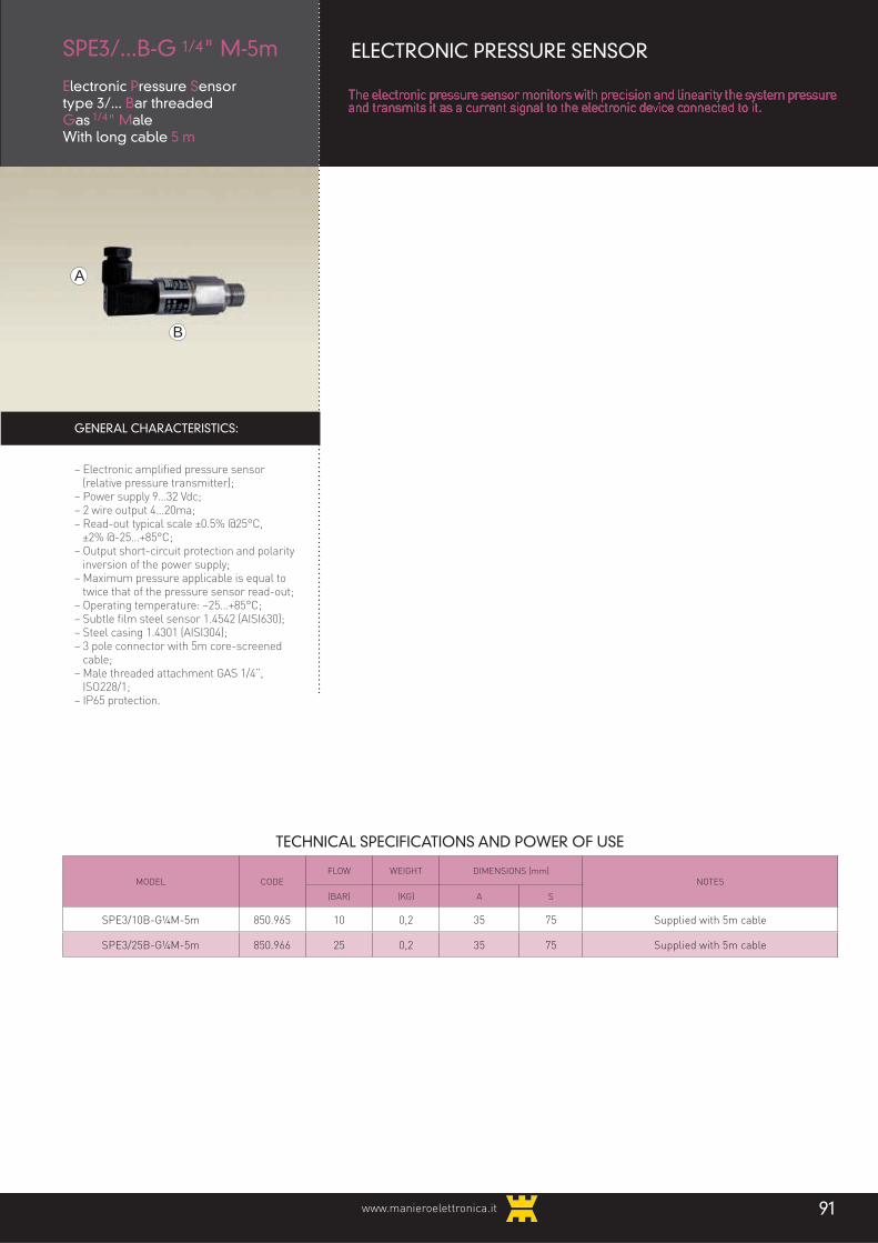
GENERAL CHARACTERISTICS:
– Electronic amplified pressure sensor (relative pressure transmitter);– Power supply 9…32 Vdc;– 2 wire output 4…20ma;– Read-out typical scale ±0.5% @25°C, ±2% @-25…+85°C;– Output short-circuit protection and polarity
inversion of the power supply;– Maximum pressure applicable is equal to
twice that of the pressure sensor read-out;– Operating temperature: −25…+85°C;– Subtle film steel sensor 1.4542 (AISI630);– Steel casing 1.4301 (AISI304);– 3 pole connector with 5m core-screened
cable;– Male threaded attachment GAS 1/4”, ISO228/1;– IP65 protection.
B
A
SPE3/...B-G 1/4" M-5m
Electronic Pressure Sensor type 3/... Bar threadedGas 1/4" MaleWith long cable 5 m
ELECTRONIC PRESSURE SENSOR
The electronic pressure sensor monitors with precision and linearity the system pressure and transmits it as a current signal to the electronic device connected to it.
91www.manieroelettronica.it
TECHNICAL SPECIFICATIONS AND POWER OF USE
MODEL CODE
FLOW WEIGHT DIMENSIONS (mm)
NOTES
(BAR) (KG) A S
SPE3/10B-G¼M-5m 850.965 10 0,2 35 75 Supplied with 5m cable
SPE3/25B-G¼M-5m 850.966 25 0,2 35 75 Supplied with 5m cable
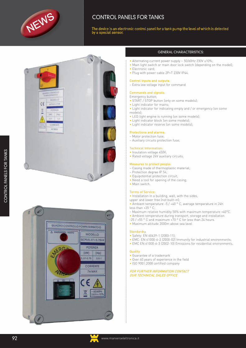
• Alternating current power supply ~ 50/60Hz 230V ±10%;
• Main light switch or main door lock switch (depending on the model);
• Electronic card;
• Plug with power cable 2P+T 230V IP44.
Control inputs and outputs:
– Extra low voltage input for command
Commands and signals:
Emergency button;
• START / STOP button (only on some models);
• Light indicator for mains;
• Light indicator for indicating empty and / or emergency (on some
models);
• LED light engine is running (on some models);
• Light indicator block (on some models);
• Light indicator reserve (on some models);
Protections and alarms:
– Motor protection fuse;
– Auxiliary circuits protection fuse;
Technical Information:
• Insulation voltage 450V;
• Rated voltage 24V auxiliary circuits.
Measures to protect people:
– Casing made of thermoplastic material;
– Protection degree IP 54;
• Equipotential protection circuit;
• Need a tool for opening of the casing;
• Main switch.
Terms of Service:
• Installation in a building, wall, with the sides,
upper and lower free (not built-in);
• Ambient temperature -5 / +40 ° C, average temperature in 24h
less than +35 ° C;
– Maximum relative humidity 50% with maximum temperature +40°C.
• Ambient temperature during transport, storage and installation
-25 / +55 ° C and maximum +70 ° C for less than 24 hours.
• Maximum altitude 2000m above sea level
Standards:
• Safety: EN 60439-1 (2000-11);
• EMC: EN 61000-6-2 (2000-02) Immunity for industrial environments;
• EMC EN 61000-6-3 (2002-10) Emissions for residential environments.
Quality
• Guarantee of a trademark
• Over 40 years of experience in the field
• ISO 9001:2008 certified company
FOR FURTHER INFORMATION CONTACTOUR TECHNICAL SALES OFFICE
GENERAL CHARACTERISTICS:
CO
NTR
OL
PAN
ELS
FOR
TA
NK
S
CONTROL PANELS FOR TANKS
The device is an electronic control panel for a tank pump the level of which is detected by a special sensor.
www.manieroelettronica.it92

www.manieroelettronica.it 93
ADDITIONALEQUIPMENT
"...We are all proudto build the success of the
company..."

www.manieroelettronica.it94
ACOUSTIC AND VISUAL WARNING SIGNALS FOR ALARM SYSTEMS IN COMPLIANCE WITH STANDARD UNI EN 12845
- Acoustic and visual electronic signal;- AC power supply: 2~ 50/60Hz 24V / 220-240V / 380-415 ± 10%;- DC power supply; 11,5-30Vdc;- Power supply from internal sealed buffer battery Pb 6V;- Acoustic warning signal 82dB(A)1m;- Flashing led indicator (on some models only);- Modular configuration in groups of 6 low voltage contact
iiiiinputs:
• 1 voltage 12-24Vac / 9-30Vdc / 220-240Vac or NC/NO type iiiiIIcontact;
• 3 NC/NO contact type configurable individually via iiii IIIIIImicroswitch;
• 1 NC contact type; • 1 NO contact type;
A
BP
TECHNICAL SPECIFICATIONS AND OPERATING POWER
MODEL CODE FLASHER
NO. OF
MODULES /
NO. OF
INPUTS
AUTONOMY
BATTERY h
in alarm at rest
POWER NOMINAL
(MAX)
WEIGHTKG
DIMENSIONS mm
A
DIMENSIONS mm
B
DIMENSIONS mm
PNOTES
SALB/6I 252.22 LED 1/6 8 18 3W 1.5 190 240 90 VERSION ON BOX
SA/6I 252.27 - 1/6 8 18 3W 2 250 250 180VERSION WITH ONLY
HORN
SAL/6I 252.28 LED 1/6 8 18 3W 2 250 250 180 6 INPUT VERSION
SAL/12I 252.37 LED 2/12 4 7 6W 3 375 250 180 12 INPUT VERSION
SAL/18I 252.38 LED 3/18 8 18 9W 4 550 350 180 18 INPUT VERSION
The range SA.../...I includes various models according to the number of inputs and the
presence of a visual flashing signal.
All products in the range are modular: this enables customisation of the system according
to specific requirements, with up to 8 connected modules
SALB/6ISA/6ISAL/6I
SAL/12ISAL/18I
- 1 low voltage NO contact type input for temporary or iiiipermanent shutoff of the acoustic signal;
- 3 contact outputs with NO / NC changeover (max. contact iiiicapacity 250V~ 5A resistive load) for alarm signal, external iiiipower supply presence, IN6 input closed;
- Commands and signals for each module: • Synoptic panel under membrane; • 2 pushbuttons for manual reset from alarm and lights
and outputs test/iiiiIIacoustic signal shutoff; • 10 display leds; Power present, buffer battery level,
input status, alarm, iiiiIIacoustic signal shut off;- Communication port with RS485 MODBUS-RTU serial
line for slave connection, iiiimaximum connection distance
iiii500m, speed 300 / 9600 / 19200 / 38400 bit/s.- Operation setting microswitches: • NC/NO polarity selection of 4 alarm contact inputs;
• Alarm duration unlimited / 5 / 30 / 60 minutes;
• Ring type continuous / intermittent (30s on - 30s off);
• Reset automatic / manual;- Communication setting microswitches: • Termination resistance activation; • Speed, master / slave operation (for Local
communication only); • Node address;
- Thermoplastic casing;- IP55 protection rating;
CONNECTIONS
GENERAL CHARACTERISTICS:
A
B
P
A
B
P
A
B
PSALB/6I SAL/12I SAL/18I
SAL/6I
230V 0 400V C IN1 IN2 IN3 IN4 IN5 IN6
CONTACT OUTPUTS
ALARM POWER SUPPLYPRESENCE
POWERSUPPLY INPUT
POWER SUPPLYINPUT
DC / AC
11,5-30Vdc24Vac
DIGITAL INPUTS
C NO NC C NO NC C NO NC0 24V 12/24V 0 230V
VOLTAGE INPUT
M C
AUXILIARYOUTPUT

www.manieroelettronica.it 95
A
A
B
B
P
P
GENERAL CHARACTERISTICS:
- Electronic acoustic and visual signaller- Power supply: • 2~ 50/60Hz 220-240V / 380-415 V±10%; • 2~ 50/60Hz 24 V / 18…30 Vdc; • Very low voltage inputs for alarm contacts NO/
NC- Main Pilot light- Led for alarm
GENERAL CHARACTERISTICS:
– Electronic flash-lamp;– Power supply 1~50/60Hz ...V±10%: • 12/24V (model LLR/3-12Vcc or 24V and LLG/3-12Vcc or 24V); • 230V~ (model LLR/3-230V and LLG/3-230V);– Yellow or red light scattering globe;– Thermoplastic box;– Protected to IP 55.
ACOUSTIC AND VISUAL WARNING DEVICES AND ACCESSORIES FOR ALARM SYSTEM
CONNECTIONS
S/...VAcousticsignalling device
SL/...VAcousticand Flashingsignalling device
– Push button for: • Tests of LEDS and outputs; • Acoustic alarm switching off; • Acoustic signaller with sound pressure 82
dB (A) 1 M with selector for continuous orIIIIintermittent mode; • Led flashing (only model SL/…V)- Type of sound: continuous or intermittent
iiiisound (30s ON – 30X OFF): • Thermoplastic box; • Protected to IP55
OPTIONAL:
- Contact output settable for signalling the iiialarm or “OK” status or acoustic signaller iiicontrol
- Output for external acoustic and visual iiisignalling devices (only version 24V).
LL../10-230VLL../3-12-24V
Red/Yellow Flashing Light 10W to 230V
Red/Yellow Flashing Light 3W to 12 or 24V
• Only version 230V:– Trimmer to regulate lamp flashing frequency, from 1 to 6 flashes/sec;– Double power input for either a fixed or a
IIIflashing light source;– Mother board protection fuse.
OUTPUT CONTACT
ALARM OUTPUT(1)
NF
EXTERNAL SIGNALS OUTPUT(2)
POWER SUPPLY INPUTALARMINPUT
IN1
24V
TECHNICAL DATA AND OPERATING POWERS
MODEL CODENOMINAL
POWER W
WEIGHT kgDIMENSIONS
mmA
DIMENSIONS mm
B
DIMENSIONS mm
PNOTE
S82/24V 253.37 2 0,6 180 120 75 VERSIONE SU BOX
S82/230-400V 253.38 2 0,8 180 120 75 VERSIONE SU BOX
SL82/24V 253.39 2 0,8 180 120 170 VERSIONE SU BOX
SL82/230-400V 253.40 2 1 180 120 170 VERSIONE SU BOX
TECHNICAL DATA AND OPERATING POWERS
MODEL CODENOMINAL
POWER W
WEIGHT kgDIMENSIONS
mmA
DIMENSIONS mm
B
DIMENSIONS mm
PNOTE
LLR/10-230V 251.66 10 0,18 90 90 65 RED, BOX VERSION
LLG/10-230V 251.67 10 0,18 90 90 65 YELLOW, BOX VERSION
LLR/3-24Vac 251.68 3 0,17 90 90 65 RED, BOX VERSION
LLG/3-24Vac 251.69 3 0,17 90 90 65 YELLOW, BOX VERSION
LLR/3-12Vcc 251.84 3 0,17 90 90 65 RED, BOX VERSION
LLG/3-12Vcc 251.85 3 0,17 90 90 65 YELLOW, BOX VERSION

www.manieroelettronica.it96
METER ULTRASONIC LEVEL TRANSMITTER
GENERAL CHARACTERISTICS:
– 3 different modes of configuration and calibration from remote unit and 1 local:
• HART Hand Held Programmer; • PC/MODEM HART; • MODBUS RTU; • LCD module (inserted on the transmitter).– 3 types of connection (depending on model): • 2-wires; • 4-wires with two threshold relays; • ATEX certified version.– 3 types of housing (depending on model): • PC (loaded polycarbonate); • Al / PP (polypropylene and aluminum); •PVDF (polyvinylidene fluoride, ATEX certified version only PVDF;– Operating temperature -30 to +70 ° C max 80 ° C (not continuous);– Protection degree IP67.
ATR121 THERMOREGULATOR
GENERAL CHARACTERISTICS:
– Regulator and viewer for the following sensors: • Temperature; • Humidity; • Pressure; • Level; • Linear potentiometer.– Provision for inserting a memory card (not included);– Made of polycarbonate UL94V0 flame retardant;– Operating temperature: max 40 ° C;– Protection degree IP65 on the front.
TECHNICAL CHARACTERISTICS
B
A
P
B
A
P
MODEL CODE WEIGHT KGDIMENSIONS
mmA
DIMENSIONS mm
B
DIMENSIONS mm
PNOTES
ATR121 632.292 0.1 35 77 60
DTA01 851.124 0.15 83.5 22.5 99.5
DTA02 851.125 0.15 83.5 22.5 99.5 With changeover contact and reset button
METER 1F4D 851.123 0.7 102 130 237Weight and dimensions are for the standard version (NO ATEX)
with 2 wires without relay and loaded polycarbonate case (PC)
DTA INTERFACE RELAY FOR PTC PROBES
GENERAL CHARACTERISTICS:
– Motor temperature monitoring;– Range of measurement: PTC in accordance with EN44081;– Output: 8A SPDT (PTA01) and (SPST DTA01) relay normally energized:
energized;– LED indication for active relay and power presence;– Galvanically isolated power.– Operating Temperature -20 to 60 ° C, RH <95%– Storage Temperature -30 to 80 ° C, RH <95%;– Protection degree IP 20
B
A
P
cod. 632.292
cod. 851.124
cod. 851.123

www.manieroelettronica.it 97
• RS232 serial port for debugging device operation on the monitor (PORT 0),
• RS485 serial port Modbus RTU Master for connection to I/O slave modules (PORT 1),
• Programmable serial port such as RS232 or RS485, if not programmed as RS485 it can be used to capture data via Modbus RTU Master / Slave (PORT 2) protocol.
– Pollution degree 2,– Protection degree IP 20
TECHNICAL SPECIFICATIONS AND POWER OF USE
GENERAL CHARACTERISTICS:
– Power supply 10 ÷ 30Vdc / 12 ÷ 24Vac; – Average consumption 100mA, 400mA in
transmission;– Built-in SIM card reader;– GSM antenna included;– WE110: • Integrated GSM / GPRS dual-band modem, • Digital input for "dry contact", • Relay output (1A, 24V), • Input for NTC temperature probe • NTC temperature probe 10kOhm at 25 ° C
included, • Connection via removable terminal block.
– WE120: • GSM / GPRS Quad band 850/900/1800/1900
integrated • No. 4 digital inputs for "dry contact", • No. 2 factory configurable analog inputs
(0÷5V, 0÷10V, 4 ÷ 20mA, PTC / NTC) • No. 2 relay outputs (1A, 24V), • No. 1 serial interface RS232 (Tx, Rx, Gnd,
RTS, CTS) on DB9 female • No. 1 serial interface RS485 on terminal.
OPERATING CONDITIONS:
– Operating temperature: • -15 ÷ +55 ° C (WE110),-25 ÷ +40 ° C (WE120).– Relative humidity 0 to 80% non-condensing.
B
A
BA
WE... REMOTE TELECONTROL UNIT
TECHNICAL SPECIFICATIONS AND POWER OF USE
MODEL CODE WEIGHT KGDIMENSIONS
mmA
DIMENSIONS mm
B
DIMENSIONS mm
PNOTES
WE110 632.524 0.105 70 57 30
WE120 632.523 0.180 90 70 65 DIN Rail Mounting
Z-RTU REMOTE TELECONTROL UNIT
Z-RTU is a single block aluminum unit, with IEC 61131 configurator and software tools necessary for remote control.Ideal solution for applications of environmental monitoring, water and sewer systems, gas control and energy management.
P
OPERATING CONDITIONS:
– Operating temperature -10...+55°C;– Storage temperature -20..+70°C,– Humidity 30 ... 90% at +40 ° C (non-
condensing).
MODEL CODE WEIGHT KGDIMENSIONS
mmA
DIMENSIONS mm
B
DIMENSIONS mm
PNOTES
Z-RTU 632.136 0.875 185 242 37 Removable screw terminals for wires up to 2.5 mm 2
ZTOP04C 632.142 1 109 149 60 Touch screen panel and cable for programming the Z-RTU
P
ugging device
GENERAL CHARACTERISTICS:
– Power supply 10-30VDC (15W max)– CPU μP RISC 32 bit– 20 MIPS,– Data Flash Memory 16MB, – RAM 8MB,– 64 retentive variables,– 8 digital inputs (with external or internal
power supply);– 2 analog inputs (with 14bit resolution and
selectable power loop);– 4 digital outputs (SPDT relay), isolated
singularly;– 1 analog output (voltage / current);– 1 internal industrial GSM module, dual-
band full type approval (as an alternative, on request, a PSTN modem may be installed);
– Communication ports: • Ethernet port for connection to the local
network,

www.manieroelettronica.it98
BP
A
CONNECTIONS
CONNECTIONS
BP
A
RCSFA2/M-...V
POWER SUPPLY INPUT 3 ~ 50/60Hz 230/400V ± 10%
ALARM RELAYOUTPUT 5A-250V
POWER SUPPLY INPUT3 ~ 50/60Hz 230/400V ± 10%
ALARM RELAYOUTPUT 8A-250V
GENERAL CHARACTERISTICS:
– Electronic phase sequence monitoring;– Power: 3~ 50/60Hz ....V ±10%:– 230 V~ (model: CSFA2/M-230 V);– 400 V~ (model: CSFA2/M-400 V);– Power signal LED;– Relay active LED (normally energised);– Alarm trigger trimmer in the event of a phase decrease in the power voltage;
GENERAL CHARACTERISTICS:
– Electronic phase sequence monitoring;– Power: 3~ 50/60Hz ....V ±10%:– 230 V~ (model: RCSFA2/M-230 V);– 400 V~ (model: RCSFA2/M-400 V);– Power signal LED;– Relay active LED (normally energised);– Alarm signal LED;– Settable start delay (1 s or 6 s);– Alarm trigger trimmer, range: -2% to -22% (lower voltage threshold);
CSFA2/M-...V
Phase sequence monitoring device with alarm (modular unit)
COMPLEMENTARY PHASE MONITORINGEQUIPMENT WITH ALARM
All items of complementary equipment for monitoring phase presence and unbalance are equipped with lower and upper voltage threshold monitoring devices and alarm outputs. These can be fitted onto any apparatus where the power line is unbalanced and subject to considerable voltage surges and drops but operation continuity and safety is essential.
It is also indispensable in situations where the equipment is continually powered by different lines and so phase sequence might be incorrect or unbalanced voltages could be experienced. For other requirements, please contact our technical/sales department.
Phase sequence monitoring control with alarm, modular unit, 8th relay output
– Alarm output relay, 1 switch (capacity: 5A 250V ~ resistive load);– Alarm triggered in the following cases:- phase failure;- phase reduction;- phase sequence error;– Enclosure for 1 DIN module made of thermoplastic material;– Protection class IP20.
– Alarm trigger trimmer, range: +2% to +22% (upper voltage threshold);– Trigger delay trimmer, range: 0.1 – 30 s;– Alarm output relay, 1 switch (capacity: 8A 250V ~ resistive load);– Alarm triggered in the following cases:- phase failure;- power voltage increase/decrease;- phase sequence error;- phase voltage unbalance;
TECHNICAL DATA AND OPERATING POWERS
MODEL CODENOMINAL
POWER W
WEIGHT kgDIMENSIONS
mmA
DIMENSIONS mm
B
DIMENSIONS mm
PNOTE
CSFA2/M-230V 838.251 7 0,08 82 17,5 67 FROM 160 TO 240 VCA
CSFA2/M-400V 838.252 13 0,08 82 17,5 67 FROM 320 TO 480 VCA
KCSFA2/M-400V 225.99 2 0,5 90 52 70 WIRED VERSION
RCSFA2/M-230V 838.253 13 0,12 80 22,5 100 DIN MODULAR VERSION
RCSFA2/M-400V 838.254 13 0,12 80 22,5 100 DIN MODULAR VERSION
– DIN modular enclosure made of thermoplastic material;– Protection class IP20.
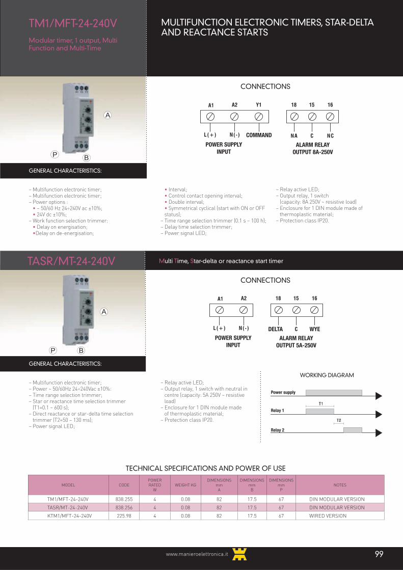
www.manieroelettronica.it 99
BP
A
CONNECTIONS
CONNECTIONS
WORKING DIAGRAM
GENERAL CHARACTERISTICS:
– Multifunction electronic timer;– Multifunction electronic timer;– Power options : • ~ 50/60 Hz 24÷240V ac ±10%; • 24V dc ±10%;– Work function selection trimmer: • Delay on energisation; •Delay on de-energisation;
GENERAL CHARACTERISTICS:
– Multifunction electronic timer;– Power ~ 50/60Hz 24÷240Vac ±10%:– Time range selection trimmer;– Star or reactance time selection trimmer (T1=0.1 – 600 s);– Direct reactance or star-delta time selection
trimmer (T2=50 – 130 ms);– Power signal LED;
BP
A
TASR/MT-24-240V Multi Time, Star-delta or reactance start timer
• Interval; • Control contact opening interval; • Double interval; • Symmetrical cyclical (start with ON or OFF
status);– Time range selection trimmer (0.1 s – 100 h);– Delay time selection trimmer;– Power signal LED;
– Relay active LED;– Output relay, 1 switch with neutral in centre (capacity: 5A 250V ~ resistive
load)– Enclosure for 1 DIN module made of thermoplastic material;– Protection class IP20.
TECHNICAL SPECIFICATIONS AND POWER OF USE
MODEL CODEPOWER RATED
WWEIGHT KG
DIMENSIONS mm
A
DIMENSIONS mm
B
DIMENSIONS mm
PNOTES
TM1/MFT-24-240V 838.255 4 0.08 82 17.5 67 DIN MODULAR VERSION
TASR/MT-24-240V 838.256 4 0.08 82 17.5 67 DIN MODULAR VERSION
KTM1/MFT-24-240V 225.98 4 0.08 82 17.5 67 WIRED VERSION
TM1/MFT-24-240VModular timer, 1 output, MultiFunction and Multi-Time
MULTIFUNCTION ELECTRONIC TIMERS, STAR-DELTA AND REACTANCE STARTS
– Relay active LED;– Output relay, 1 switch (capacity: 8A 250V ~ resistive load)– Enclosure for 1 DIN module made of
thermoplastic material;– Protection class IP20.
POWER SUPPLYINPUT
COMMAND
ALARM RELAYOUTPUT 8A-250V
POWER SUPPLYINPUT
DELTA WYE
ALARM RELAYOUTPUT 5A-250V
Power supply
Relay 1
Relay 2

www.manieroelettronica.it100
MS20 / RExchanger module for 2 electric pumps (2nd delayed)
EXCHANGERS AND ELECTRONIC MODULESFOR PANELS
A
GENERAL CHARACTERISTICS:
– Start sequence exchanger for two electric pumps;
– Module equipped with connector for link up to all our panels configured for 2 or 3
electric pumps;– The MS20/R module delays pump 2iiistart by approximately 4” on closure of floatiiiswitch 2.
GENERAL CHARACTERISTICS:
– Start sequence exchanger for 2 - 3 or 4 electric pumps;– Module equipped with connector for link up to all our panels configured for 3 or 4 electric pumps;– Start delay selector for pumps 3 and 4;– Selector for operation with 2 - 3 or 4 electric pumps to allow start sequence switching.
GENERAL CHARACTERISTICS:
– Alarm signal module;– Module equipped with connector for link up to all our pre-configured panels;– This module signals when either the MIN/MAX WATER LEVEL or the overload protection has been triggered;– External output for alarm operation via pressure switch or floating switch (NO contact);– Relay output 1A 250V (resistive load) NO-NC contacts for external alarm control;– Available with flat conductor (100 and 300 mm).
B
B
B
A
A
MS40
MA/1
Exchanger Module for 2-3 or 4 motor pumps
Alarm Module with 1 changeover relay
TECHNICAL DATA AND OPERATING POWERS
MODEL CODEPOWER RATED
WWEIGHT KG
DIMENSIONS mm
A
DIMENSIONS mm
B
DIMENSIONS mm
PNOTES
MS20/R 221.39 0.5 0.03 45 47 15 OPEN VERSION
MS40 221.40 0.5 0.06 50 100 25 OPEN VERSION
MA/1-100mm 221.23 0.5 0.04 50 30 30 OPEN VERSION
MA/1-100mm 221.70 0.5 0.04 50 30 30 VERSION FOR QMD20/SI-2
MA/1-300mm 221.24 0.5 0.04 50 30 30 OPEN VERSION
WORKING DIAGRAM
WORKING DIAGRAM
PUMP 1
PUMP 2
SL/SP 1
SL/SP 2
SL/SP 3
SL/SP 4
PUMP 1
PUMP 2
PUMP 3
PUMP 4
3 SECONDS

www.manieroelettronica.it 101
GENERAL CHARACTERISTICS:
– Electronic level control module;– Module equipped with connector for link up to all
IIIour preconfigured panels;– 2-sensor input for timed operation control;– Sensor sensing trimmer;– Trigger delay trimmer, range: approx. 5 – 20 min;– FILLING or DRAINING operation mode selectors;– Voltage at sensor ends: approx. 10 V~;– Module suitable for non-inflammable conductive
iiiliquids;– Available with flat conductor (90 or 300 mm).
GENERAL CHARACTERISTICS:
– Electronic level control module;– Module equipped with connector for link up to all
iiiour preconfigured panels;– Input for 3 sensors or 2 float switches;– Sensor sensing trimmer;– FILLING or DRAINING operation mode selectors;– Voltage at sensor ends: approx. 10 V~;– Module suitable for non-inflammable conductive
iiiliquids;– Available with flat conductor (90 or 300 mm).
GENERAL CHARACTERISTICS:
– Electronic module for timed on/off function;– Module equipped with connector for link up to all
iiiour preconfigured panels;– Trigger delay trimmer (approx. 0 - 120”) for
iiienergising or de-energising electric pump after, iiirespectively, closure or opening of external control iiicontact (pressure switch/float switch);
– Selectors for operation in energised or de-iiienergised mode;
– Available with 400 mm flat conductor.
B
B
B
A
A
A
MCL/3S
MR/ED-120"
3-Sensor level control module
Energisation/de-energisation delay module - 120”
TECHNICAL DATA AND OPERATING POWERS
MODEL CODE WEIGHT KGDIMENSIONS
mmA
DIMENSIONS mm
B
DIMENSIONS mm
PNOTES
MCL/2ST-300mm 221.04 0.04 50 45 30 OPEN VERSION
MCL/2ST-90mm 221.02 0.04 50 45 30 OPEN VERSION
MCL/3S-300mm 221.05 0.04 50 45 30 OPEN VERSION
MCL/3S-90mm 221.30 0.04 50 45 30 OPEN VERSION
MR/ED-120”-400mm 221.12 0.04 50 45 30 OPEN VERSION
MCL/2ST
Timed 2-sensor levelcontrol module
ELECTRONIC MODULES FOR CONTROL PANELS
The application of electronic modules to our pre-configured panels allow users to extend the system’s range of functions as desired. Great financial savings can be made thanks to our forward thinking at the design stage, which means no labour is required for additional wiring and the power supply is already integrated into the panel’s circuit.
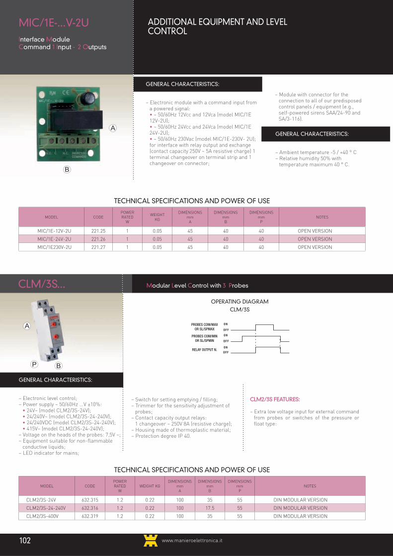
www.manieroelettronica.it102
GENERAL CHARACTERISTICS:
– Electronic module with a command input from a powered signal:
• ~ 50/60Hz 12Vcc and 12Vca (model MIC/1E 12V-2U);
• ~ 50/60Hz 24Vcc and 24Vca (model MIC/1E 24V-2U);
• ~ 50/60Hz 230Vac (model MIC/1E-230V- 2U); for interface with relay output and exchange (contact capacity 250V ~ 5A resistive charge) 1 terminal changeover on terminal strip and 1 changeover on connector;
GENERAL CHARACTERISTICS:
– Ambient temperature -5 / +40 ° C– Relative humidity 50% with
temperature maximum 40 ° C.B
A
– Module with connector for the connection to all of our predisposed control panels / equipment (e.g., self-powered sirens SAA/24-90 and SA/3-116).
MIC/1E-...V-2UInterface Module Command 1 Input - 2 Outputs
ADDITIONAL EQUIPMENT AND LEVEL CONTROL
CLM2/3S FEATURES:
– Extra low voltage input for external command from probes or switches of the pressure or float type:
– Switch for setting emptying / filling;– Trimmer for the sensitivity adjustment of
probes;– Contact capacity output relays:
1 changeover ~ 250V 8A (resistive charge);– Housing made of thermoplastic material;– Protection degree IP 40.
GENERAL CHARACTERISTICS:
– Electronic level control;– Power supply ~ 50/60Hz ...V ±10%: • 24V~ (model CLM2/3S-24V); • 24/240V~ (model CLM2/3S-24-240V); • 24/240VDC (model CLM2/3S-24-240V); • 415V~ (model CLM2/3S-24-240V);– Voltage on the heads of the probes: 7,5V ~;– Equipment suitable for non-flammable
conductive liquids;– LED indicator for mains;
A
BP
CLM/3S... Modular Level Control with 3 Probes
TECHNICAL SPECIFICATIONS AND POWER OF USE
MODEL CODEPOWERRATED
WWEIGHT KG
DIMENSIONS mm
A
DIMENSIONS mm
B
DIMENSIONS mm
PNOTES
CLM2/3S-24V 632.315 1.2 0.22 100 35 55 DIN MODULAR VERSION
CLM2/3S-24-240V 632.316 1.2 0.22 100 17.5 55 DIN MODULAR VERSION
CLM2/3S-400V 632.319 1.2 0.22 100 35 55 DIN MODULAR VERSION
OPERATING DIAGRAMCLM/3S
RELAY OUTPUT N.
PROBES COM/MAXOR SL/SPMAX
PROBES COM/MINOR SL/SPMIN
TECHNICAL SPECIFICATIONS AND POWER OF USE
MODEL CODEPOWERRATED
W
WEIGHTKG
DIMENSIONS mm
A
DIMENSIONS mm
B
DIMENSIONS mm
PNOTES
MIC/1E-12V-2U 221.25 1 0.05 45 40 40 OPEN VERSION
MIC/1E-24V-2U 221.26 1 0.05 45 40 40 OPEN VERSION
MIC/1E230V-2U 221.27 1 0.05 45 40 40 OPEN VERSION

www.manieroelettronica.it 103
closedopen
closedopen
closedopen
closedopen
onoffPUMP 1
PUMP 2
PUMP 3
PUMP 4
R = 3 seconds
onoff
onoff
onoff
OPERATING DIAGRAM
GENERAL CHARACTERISTICS:
- Electronic Exchanger- Power supply 50/50 Hz … +- 10% • 24V (model SM2R/24V) • 220/240V - (model SM2R/240V)- the module delays the start up of the 2 pump
ofI4” at the closure of all the floats- Main pilot light- Main pilot light
- Red LED of output status relays- Very low voltage for external control from
pressure or float switches- Contact capacity n. 2 output relays: 1 NO 8 A
250V (resistive load)- 3 DIN modules thermoplastic box- Protected to IP40
A
BP
ELECTRONIC EXCHANGERS AND SEQUENCER
Whenever it is necessary to switch a sequence from 2 to 4 loads (motors, lamps, electric pumps, etc.) we propose, for all the most common voltages, a range of 17 models of electronic switches-sequencers with the possibility, at no extra charge, to ask for other models with different characteristics.
BOX VERSION SB4/230-400V:
– Output with cable holder;– Protection degree IP 55.
OPEN VERSION: SG4/230-400V:
– Electronic card equipped with fastening distance brackets.
pumps;– Power contacts of N° 4 output relays: 1 (NO) 10A 250V~ (resistive load);– Selector for delayed start for 3rd and 4th
pumps.
GENERAL CHARACTERISTICS:
– Electronic exchanger-sequencer;– Power supply 1~ 50/60Hz 230/400V±10%;– Very low voltage inputs for external control
from pressure or float switch;– Main pilot light;– N° 4 motor control lights;– Selector for exchange to 2, 3 or 4 electric
A
BP
S..4/...V Exchanger - sequencer (in 2 versions) for 4 electric pumps
OPERATING DIAGRAM
RELAY 1
RELAY 2
SM2R/24V
Exchanger for 2 pumps
TECHNICAL DATA AND OPERATING POWERS
MODEL CODENOMINAL
POWERW
WEIGHT kgDIMENSIONS
mmA
DIMENSIONS mm
B
DIMENSIONS mm
PNOTE
SM2R/24V 632.317 2 0,25 90 53,5 60 DIN MODULAR VERSION
SM2R/240V 632.318 2 0,25 90 53,5 60 DIN MODULAR VERSION
SB4/230-400V 251.78 4 1,00 150 200 80 BOX VERSION
SG4/230-400V 251.77 4 0,50 105 145 70 OPEN VERSION

www.manieroelettronica.it104
IPE/...BAR-...V Electromechanic pressure switch
GENERAL CHARACTERISTICS:
Power supply 1~ 50/60 Hz 230 ±10%;– 1/4” screwed gas flange, female;– Polyester box;– 1,5kW maximum load;– Ambient temperature -30/+80°C;– Fluid max temperature 70°C;– Maximum operating frequency: 600 manoeuvre
cycles per hour;– Protection degree IP 20.
TECHNICAL SPECIFICATIONS AND POWER OF USE
MODEL CODE WEIGHT KGDIMENSIONS
mmA
DIMENSIONS mm
BNOTES
SL1/00 851.049 0.06 100 18 PROBE WITHOUT CABLE
SL1/1m 851.140 100 18 PROBE WITH CABLE
SL1/5m 851.141 100 18 PROBE WITH CABLE
SL1/10m 851.142 100 18 PROBE WITH CABLE
SL1/20m 851.143 100 18 PROBE WITH CABLE
SL1/30m 851.144 100 18 PROBE WITH CABLE
SL1/50m 851.145 100 18 PROBE WITH CABLE
SL1/70m 851.146 100 18 PROBE WITH CABLE
SL1/100m 851.147 100 18 PROBE WITH CABLE
UNIPOLAR CABLE S1 704.188 - - - CABLE FOR PROBES 1mm2 SILICONE
SL1/...Level Sensors 1 electrode with and without cable
ELECTRONIC PROBES FOR CONTROL LEVEL
GENERAL CHARACTERISTICS:
– Unipolar level sensor;– Inox steel 70mm electrode;– PVC covering;– In level sensors without cable, the terminal input
is equipped with a goble gland;– In level sensors with cable the terminal is
immersed in resin;– Working temperature: max 40°C;– On request level sensors with cable can be
IIIsupplied in different cable lenghts.
B B
A A
TECHNICAL SPECIFICATIONS AND POWER OF USE
MODEL CODE PRESSURE (BAR)POWER
(W)WEIGHT
KG
DIMENSIONS mm
A
DIMENSIONS mm
B
DIMENSIONS mm
P
IPE/5BAR-230V 851.120 1.5 0.35 102 72 96
IPE/7BAR-230V 851.121 1.5 0.35 102 72 96
IPE/10BAR-230V 851.122 1.5 0.35 102 72 96

www.manieroelettronica.it 105
GENERAL CHARACTERISTICS:
– Silver contacts;– Contacts capacity 10(4) A at 250V~;– Microswitch: 1 exchange contact;– Thermoplastic box;– Max temperature: 40°C;– Protection degree IP 67.
N.B.: the counterweight should be ordered separately.
N.B.: the counterweight should be ordered separately.
GENERAL CHARACTERISTICS:
– Watertight to a depth of 100m, resistant to humidity and condensation;
– External box in a single piece of blow- molded polyethylene;
– Internal counterweight to adjust the centre of gravity towards the cable entry point and to determine the rotation point;
- it is built with innovative electrical contacts made up of a 10A 250Vca change-over switch with self-cleaning contacts and a high opening distance.
– Protection degree IP68. OPERATING CONDITIONS:
– max working temperature 55°C.
WORKING:
– Regulation for particularly turbulent industrial water with suspended binding residues or ii
water laden with sewage waste;– Where there is a deep and narrow sump pit
controlling the flow on two different levels.
B
A
B
B
A A
IGS-.../10m-AR Watertight mechanical float switch for sewage
TECHNICAL DATA AND OPERATING POWERS
TECHNICAL DATA AND OPERATING POWERS
MODEL CODE WEIGHT KGDIMENSIONS
mmA
DIMENSIONS mm
B
DIMENSIONS mm
PNOTES
IGS/5m 851.102 0.60 160 90 45 FLOAT SWITCH WITH 5m PVC CABLE
IGS/10m 851.103 1.20 160 90 45 FLOAT SWITCH WITH 10m PVC CABLE
IGS/20m 851.104 2 160 90 45 FLOAT SWITCH WITH 20m PVC CABLE
CGS (on request) 851.100 0.12 70 58 - COUNTERWEIGHT FOR FLOAT SWITCHES
IGS/CN-5m 851.106 0.60 160 90 45 FLOAT SWITCH WITH 5m NEOPRENE CABLE
IGS/CN10m 851.107 1.20 160 90 45 FLOAT SWITCH WITH 10m NEOPRENE CABLE
IGS/CN-20m 851.108 2.20 160 90 45 FLOAT SWITCH WITH 20m NEOPRENE CABLE
MODEL CODE WEIGHT KGDIMENSIONS
mmA
DIMENSIONS mm
B
DIMENSIONS mm
PNOTES
IGS-MC/10m-AR 851,079 1.30 175 80 - MECHANICAL SWITCH WITH 10m CABLE
CGS (on request) 851,100 0.12 70 58 - COUNTERWEIGHT FOR WATERTIGHT FLOAT SWITCH
IGS/...mWatertight float switches
FLOAT SWITCHES
Our electromechanical floating and pressure switches are offered for all hydraulic systems, in particular, for our overflow protection kits. The cable available for the floating switches comes in a variety of types and lengths.
P

www.manieroelettronica.it106
TECHNICAL SPECIFICATIONS AND POWER OF USE
TECHNICAL SPECIFICATIONS AND POWER OF USE
MODEL CODEMEASUREMENT
ACTIVATION(KM/H)
MEASUREMENTRESET(KM/H)
MAX CAPACITYRELAY
DIMENSIONSMM
A
DIMENSIONSMMB
DIMENSIONSMMP
ANEMOMETER 878.946 15 ÷ 56 13 ÷ 32 5A 250V 130 120 120
MODEL CODEMEASUREMENT
ACTIVATION(MM)
POWER(W)
MAX CAPACITYTRIAC
DIMENSIONSMM
A
DIMENSIONSMMB
DIMENSIONSMMP
RAIN SENSOR 878.947 4 1.5 2A 30Vac 70 80 60
ANEMOMETER
RAIN SENSOR
ANEMOMETER
RAIN SENSOR
GENERAL CHARACTERISTICS:
– Measuring range activation contact 19 ... 56km / h;– Measuring range resetting contact 13 ... 32km / h;– Changeover contact output;– Protection degree IP 56.
GENERAL CHARACTERISTICS:
– Power supply 20V ... 30Vac;– Activation after 4mm of rainfall;– Triac output;– Protection degree IP68.
B
B
A
A
The anemometer allows you to switch a switching contact based on the presence and strength of the wind. In particular, this model allows you to adjust the maximum speed for activating the contact and the minimum speed for resetting the contact.
The sensor can be installed on all systems that operate with a voltage of 20Vac and 30Vac. The sensor switches the contact after about 4mm of rain and is designed to operate even in adverse conditions, including higher and lower temperatures. The sensor is waterproof and does not require any maintenance, it ensures long lasting performance
P
P

www.manieroelettronica.it 107
ACCESSORIES FORCONTROL PANELS
"...Every day, we putourselves on the line as
individualsand as a company..."

www.manieroelettronica.it108
TM PLTimer Module Rest-Work
ACCESSORIES FOR CONTROL PANELSTIMER, HOUR METER
GENERAL CHARACTERISTICS:
– Power supply 24 ÷ 230Vac/Vdc ± 15%;– Changeover output contact 8A 250V~ (Resistive
load);– Enable input for work-rest cycle start;– Rest time adjustable on front 10 to 100%;– Work time adjustable on front 10 to 100%;– Green LED indicator for power supply presence;– Red LED indicator for relay state signaling;– Protection degree IP40 on the front (front
trimmer for adjustments), IP20 terminals.
B
B
B
A
A
A
P
P
P
TECHNICAL SPECIFICATIONS AND POWER OF USE
MODEL CODE WEIGHT KGDIMENSIONS
mmA
DIMENSIONS mm
B
DIMENSIONS mm
PNOTES
MODULAR PAUSE-DUTY DAILY
TIMER878.933 0.06 90 17.5 60 DIN MODULAR VERSION
MODULARDAILY TIMER 670.103 0.11 80 35 59 DIN MODULAR VERSION
MODULARDAILY TIMER 670.093 0.07 90 17.5 60 DIN MODULAR VERSION
PANEL DAILY TIMER 670.083 0.20 72 72 47 WALL OR PANEL VERSION
The daily and weekly timers and hour counters are offered both individually and pre-wired on the control panels, in which case the cost is already inclusive of cables and cabling work. Useful equipment whenever special cycles are needed to turn on or off motor pumps, valves, etc..
* All components and accessories that are supplied with the description "wired" are already wired in the requested equipment and the price already includes the relative labor.
For the other components it indicates the price of the single piece.
GENERAL CHARACTERISTICS:
– Power supply 1 ~ 50/60Hz 230V ± 15%;– Changeover output contact 16A 250V~ (Resistive
load);– Power reserve: 100h after a charge of 48 hours
uninterrupted;– No. 96 switches (48 start and 48 off) with
captive riders;– Minimum time for maneuver: 15 minutes;– Housing: 2 DIN modules in self-extinguishing
thermoplastic material;– Cable Kit cabling;– Protection degree IP 20.
MTG/M-1 Daily Timer Module mechanical Modular wired in the control panel
GENERAL CHARACTERISTICS:
– Power supply 230V~ ±15% 50/60Hz:– NO contact output 10A 250V~ (Resistive load);– Power reserve: 100h after a charge of 48 hours
uninterrupted;– No. 96 switches (48 start and 48 off) with
captive riders;– Minimum time for maneuver: 15 minutes;– Housing: 1 DIN module in self-extinguishing
thermoplastic material;– Cable Kit cabling;– Protection degree IP 20.
MTG/1-1U Daily Timer Module 1 Module with 1 Output, cabled in the control panel
cod. 878,933
cod. 670.093

www.manieroelettronica.it 109
B
B
B
A
A
A
P
P
P
MTS/P-1-84Weekly Timer Modulemechanical from Panel 1 output 84 switching wired in the control panel
ACCESSORIES FOR CONTROL PANELS
GENERAL CHARACTERISTICS:
– Power supply 1 ~ 50/60Hz 230V ± 15%;– Changeover output contact 10A 250V~
(Resistive load);– Power reserve: 100h after a charge of 48 hours
uninterrupted;– No. 84 switches (42 start and 42 off) with
captive riders;– Minimum time for maneuver: 120 minutes;– Wall or panel installation;– Cable Kit cabling;– Panel of standardized size 72x72;
TECHNICAL SPECIFICATIONS AND POWER OF USE
MODEL CODE WEIGHT KGDIMENSIONS
mmA
DIMENSIONS mm
B
DIMENSIONS mm
PNOTES
PANEL WEEKLY TIMER 670.086 0.20 72 72 47 WALL OR PANEL VERSION
MODULAR WEEKLY TIMER 670.106 0.13 85 35 57 DIN MODULAR VERSION
MECHANICAL TIMER 24V 670.094 0.17 55 55 55 PANEL VERSION
MECHANICAL TIMER 230V 670.096 0.14 55 55 55 PANEL VERSION
* All components and accessories that are supplied with the description "wired" are already wired in the requested equipment and the price already includes the relative labor.
For the other components it indicates the price of the single piece.
GENERAL CHARACTERISTICS:
– Timer module Weekly / Daily Programmable;– Power supply 1 ~ 50/60Hz 230V ± 10%;– Changeover output contact 16A 250V~
(Resistive load);– Power reserve: 5 years after 24 hours of
charge;– No. 1440 switches (720 Startings and 720
shutdowns) repeatable in blocks of days;– Minimum adjustable interval and hourly
resolution: 1 second;– Wiring Cable Kit;
MTS/7 Weekly Timer Module 7 days wired in the control panel
GENERAL CHARACTERISTICS:
– Analog hour meter;– Power supply 24V~ 0/230V:– Operating frequency 50Hz;– Resolution 36 / 2 or 6 minutes;– Capacity 5 digits (analog hour meters).
KCO/...-V Kit Hour Meter wired in the control panel
– Housing: 2 DIN modules in self-extinguishing thermoplastic material;
– Protection degree IP 20
cod. 670.086
cod. 670.106
cod. 670.094cod. 670.096

www.manieroelettronica.it110
ACCESSORIES FOR CONTROL PANELS
CAPACITORS FOR STARTING MOTORS
MODEL CODE CAPACITY μF NOTES
COND/2 μF 643.291 2 DOUBLE FASTON WITHOUT SHANK
COND/2.5 μF 643.292 25 DOUBLE FASTON WITHOUT SHANK
COND/3.15 μF 643.293 315 DOUBLE FASTON WITHOUT SHANK
COND/4 μF 643.299 4 DOUBLE FASTON WITHOUT SHANK
COND/6 μF 643.294 6 DOUBLE FASTON WITHOUT SHANK
COND/8 μF 643.295 8 DOUBLE FASTON WITHOUT SHANK
COND/10 μF 643.297 10 DOUBLE FASTON WITHOUT SHANK
COND/12.5 μF 643.298 125 DOUBLE FASTON WITHOUT SHANK
COND/16 μF 643.300 16 DOUBLE FASTON WITHOUT SHANK
COND/20 μF 643.302 20 DOUBLE FASTON WITHOUT SHANK
COND/25 μF 643.303 25 DOUBLE FASTON WITHOUT SHANK
COND/30 μF 643.304 30 DOUBLE FASTON WITHOUT SHANK
COND/35 μF 643.305 35 DOUBLE FASTON WITHOUT SHANK
COND/40 μF 643.306 40 DOUBLE FASTON WITHOUT SHANK
COND/45 μF 643.308 45 DOUBLE FASTON WITHOUT SHANK
COND/50 μF 643.309 50 DOUBLE FASTON WITHOUT SHANK
COND/60 μF 643.310 60 DOUBLE FASTON WITHOUT SHANK
COND/70 μF 643.311 70 DOUBLE FASTON WITHOUT SHANK
COND/75 μF 643.313 75 DOUBLE FASTON WITHOUT SHANK
COND/80 μF 643.312 80 DOUBLE FASTON WITHOUT SHANK
CAPACITOR KIT COMPLETE WITH WIRING
MODEL CODE CAPACITY μF NOTES
KCC/16 22616 16 Wired capacitor kit *
KCC/20 226.20 20 Wired capacitor kit *
KCC/25 226.25 25 Wired capacitor kit *
KCC/30 226.30 30 Wired capacitor kit *
KCC/35 226.35 35 Wired capacitor kit *
KCC/40 226.40 40 Wired capacitor kit *
KCC/45 226.45 45 Wired capacitor kit *
KCC/50 226.50 50 Wired capacitor kit *
KCC/60 226.60 60 Wired capacitor kit *
KCC/70 226.70 70 Wired capacitor kit *
KCC/75 226.75 75 Wired capacitor kit *
KCC/80 226.80 80 Wired capacitor kit *
* All components and accessories that are supplied with the description "wired" are already wired in the
requested equipment and the price already includes the relative labor. For the other components it indicates the
price of the single piece.
CIRCUIT BREAKER FOR STARTING MOTORS
MODEL CODE CAPACITY μF NOTES
CAPACIT+BREAKER 50μF 643.327 40 Pre-wired with faston (L = 20cm)
CAPACIT+BREAKER 50μF 643.321 50 Pre-wired with faston (L = 20cm)
CAPACIT+BREAKER 60μF 643.328 60 Pre-wired with faston (L = 20cm)
CAPACIT+BREAKER 85μF 643.325 85 Pre-wired with faston (L = 20cm)
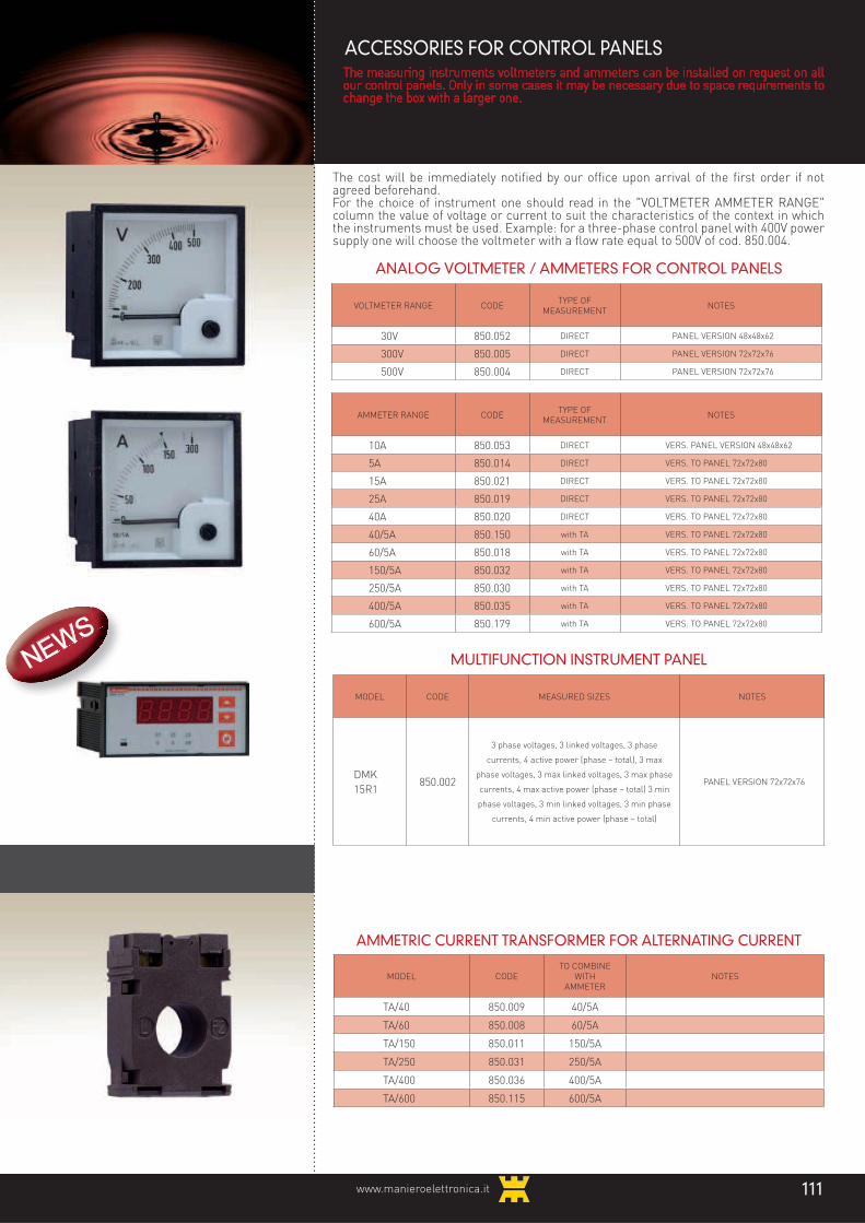
www.manieroelettronica.it 111
AMMETRIC CURRENT TRANSFORMER FOR ALTERNATING CURRENT
MODEL CODETO COMBINE
WITHAMMETER
NOTES
TA/40 850.009 40/5A
TA/60 850.008 60/5A
TA/150 850.011 150/5A
TA/250 850.031 250/5A
TA/400 850.036 400/5A
TA/600 850.115 600/5A
ANALOG VOLTMETER / AMMETERS FOR CONTROL PANELS
ACCESSORIES FOR CONTROL PANELS
The cost will be immediately notified by our office upon arrival of the first order if not agreed beforehand.For the choice of instrument one should read in the "VOLTMETER AMMETER RANGE" column the value of voltage or current to suit the characteristics of the context in which the instruments must be used. Example: for a three-phase control panel with 400V power supply one will choose the voltmeter with a flow rate equal to 500V of cod. 850.004.
AMMETER RANGE CODETYPE OF
MEASUREMENTNOTES
10A 850.053 DIRECT VERS. PANEL VERSION 48x48x62
5A 850.014 DIRECT VERS. TO PANEL 72x72x80
15A 850.021 DIRECT VERS. TO PANEL 72x72x80
25A 850.019 DIRECT VERS. TO PANEL 72x72x80
40A 850.020 DIRECT VERS. TO PANEL 72x72x80
40/5A 850.150 with TA VERS. TO PANEL 72x72x80
60/5A 850.018 with TA VERS. TO PANEL 72x72x80
150/5A 850.032 with TA VERS. TO PANEL 72x72x80
250/5A 850.030 with TA VERS. TO PANEL 72x72x80
400/5A 850.035 with TA VERS. TO PANEL 72x72x80
600/5A 850.179 with TA VERS. TO PANEL 72x72x80
The measuring instruments voltmeters and ammeters can be installed on request on all our control panels. Only in some cases it may be necessary due to space requirements to change the box with a larger one.
MULTIFUNCTION INSTRUMENT PANEL
MODEL CODE MEASURED SIZES NOTES
DMK
15R1850.002
3 phase voltages, 3 linked voltages, 3 phase
currents, 4 active power (phase – total), 3 max
phase voltages, 3 max linked voltages, 3 max phase
currents, 4 max active power (phase – total) 3 min
phase voltages, 3 min linked voltages, 3 min phase
currents, 4 min active power (phase – total)
PANEL VERSION 72x72x76
VOLTMETER RANGE CODETYPE OF
MEASUREMENTNOTES
30V 850.052 DIRECT PANEL VERSION 48x48x62
300V 850.005 DIRECT PANEL VERSION 72x72x76
500V 850.004 DIRECT PANEL VERSION 72x72x76
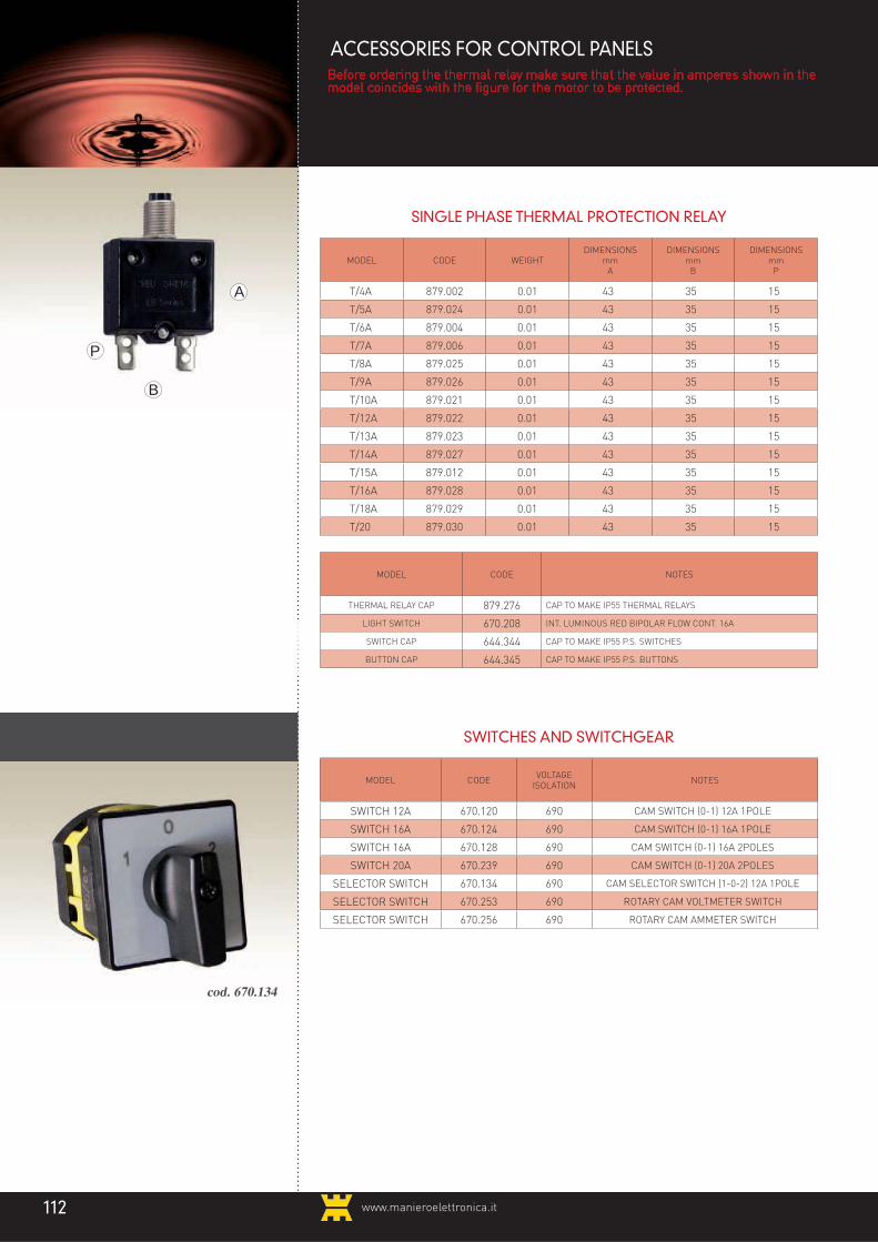
www.manieroelettronica.it112
ACCESSORIES FOR CONTROL PANELS
SINGLE PHASE THERMAL PROTECTION RELAY
MODEL CODE WEIGHTDIMENSIONS
mmA
DIMENSIONS mm
B
DIMENSIONS mm
P
T/4A 879.002 0.01 43 35 15
T/5A 879.024 0.01 43 35 15
T/6A 879.004 0.01 43 35 15
T/7A 879.006 0.01 43 35 15
T/8A 879.025 0.01 43 35 15
T/9A 879.026 0.01 43 35 15
T/10A 879.021 0.01 43 35 15
T/12A 879.022 0.01 43 35 15
T/13A 879.023 0.01 43 35 15
T/14A 879.027 0.01 43 35 15
T/15A 879.012 0.01 43 35 15
T/16A 879.028 0.01 43 35 15
T/18A 879.029 0.01 43 35 15
T/20 879.030 0.01 43 35 15
B
A
P
Before ordering the thermal relay make sure that the value in amperes shown in the model coincides with the figure for the motor to be protected.
SWITCHES AND SWITCHGEAR
MODEL CODEVOLTAGE
ISOLATIONNOTES
SWITCH 12A 670.120 690 CAM SWITCH (0-1) 12A 1POLE
SWITCH 16A 670.124 690 CAM SWITCH (0-1) 16A 1POLE
SWITCH 16A 670.128 690 CAM SWITCH (0-1) 16A 2POLES
SWITCH 20A 670.239 690 CAM SWITCH (0-1) 20A 2POLES
SELECTOR SWITCH 670.134 690 CAM SELECTOR SWITCH (1-0-2) 12A 1POLE
SELECTOR SWITCH 670.253 690 ROTARY CAM VOLTMETER SWITCH
SELECTOR SWITCH 670.256 690 ROTARY CAM AMMETER SWITCH
cod. 670.134
MODEL CODE NOTES
THERMAL RELAY CAP 879.276 CAP TO MAKE IP55 THERMAL RELAYS
LIGHT SWITCH 670.208 INT. LUMINOUS RED BIPOLAR FLOW CONT. 16A
SWITCH CAP 644.344 CAP TO MAKE IP55 P.S. SWITCHES
BUTTON CAP 644.345 CAP TO MAKE IP55 P.S. BUTTONS

Only a clean technology can bring great joy.
We are one of the main points of reference in the field of photovoltaics and energy savings, both in domestic and industrial.The excellence of the service and the extremely high quality of our systems, are factors that make us unique and ever closer to you.
Turnkey photovoltaic systems
MANIERO ELETTRONICA srlVia Chiusa, 1/B - 35020 S. Angelo di Piove (PD) - Tel. +39 049 5846688 - Fax +39 049 5847688
[email protected] - www.manieroelettronica.it
thefuturesmilesatyou
Production and control of energy

MANIERO ELETTRONICA srl35020 S. Angelo di Piove (PD)
Via Chiusa, 1/BTel. +39 049 5846688Fax +39 049 5847688
P.IVA [email protected]
RE
V. 1
1-20
11
PRODUCTION AND CONTROL OF ENERGY