Embed Size (px)
Citation preview
Product Specifications
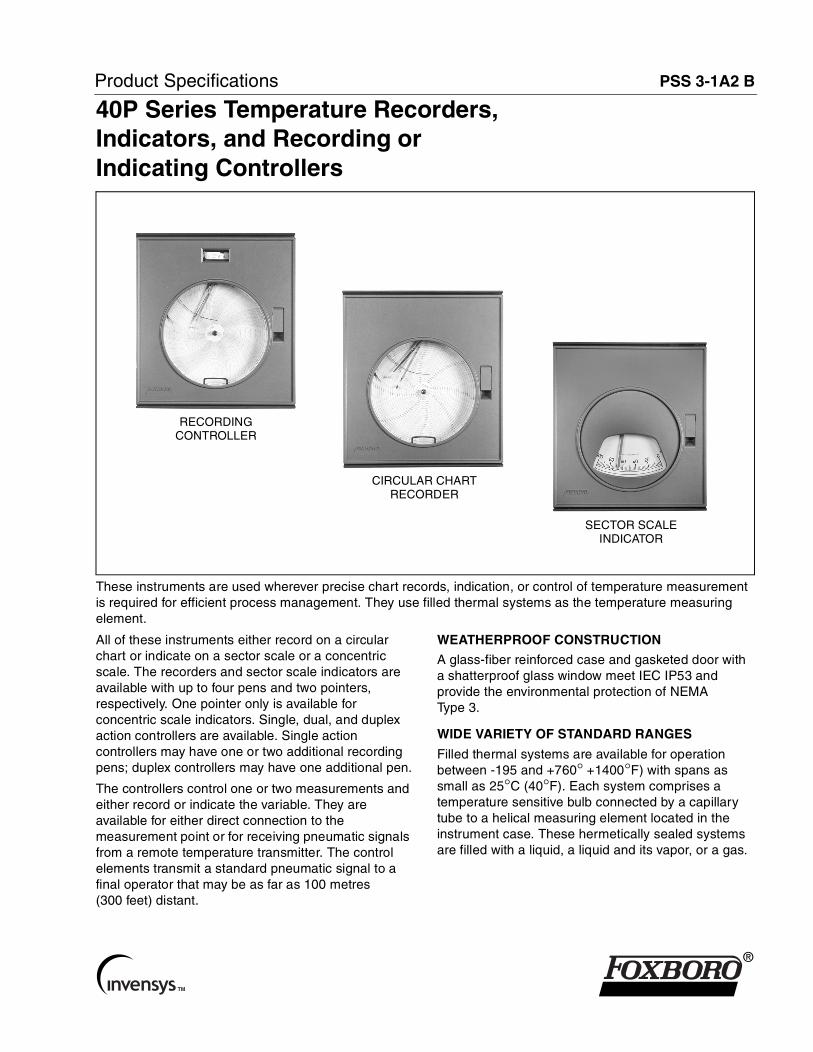
PSS 3-1A2 B40P Series Temperature Recorders,Indicators, and Recording orIndicating Controllers
RECORDINGCONTROLLER
CIRCULAR CHARTRECORDER
SECTOR SCALEINDICATOR
These instruments are used wherever precise chart records, indication, or control of temperature measurement is required for efficient process management. They use filled thermal systems as the temperature measuring element.
All of these instruments either record on a circular chart or indicate on a sector scale or a concentric scale. The recorders and sector scale indicators are available with up to four pens and two pointers, respectively. One pointer only is available for concentric scale indicators. Single, dual, and duplex action controllers are available. Single action controllers may have one or two additional recording pens; duplex controllers may have one additional pen.
The controllers control one or two measurements and either record or indicate the variable. They are available for either direct connection to the measurement point or for receiving pneumatic signals from a remote temperature transmitter. The control elements transmit a standard pneumatic signal to a final operator that may be as far as 100 metres (300 feet) distant.
WEATHERPROOF CONSTRUCTION
A glass-fiber reinforced case and gasketed door with a shatterproof glass window meet IEC IP53 and provide the environmental protection of NEMA Type 3.
WIDE VARIETY OF STANDARD RANGES
Filled thermal systems are available for operation between -195 and +760° +1400°F) with spans as small as 25°C (40°F). Each system comprises a temperature sensitive bulb connected by a capillary tube to a helical measuring element located in the instrument case. These hermetically sealed systems are filled with a liquid, a liquid and its vapor, or a gas.
®
PSS 3-1A2 BPage 2
VERSATILE MOUNTING
These instruments may be mounted in a panel, on a surface, or on a vertical pipe.
WIDE SELECTION OF CONTROL MODES
The controllers are available with On-Off, Proportional, Proportional plus Derivative, Proportional plus Integral (Reset) (STABILOG), and Proportional plus Integral plus Derivative (HYPER-RESET) control functions.
PERFORMANCE SPECIFICATIONS
(Under Reference Operating Conditions)
AccuracyWhen using the elements as listed in Measuring Element Specifications section.CLASS IA
Spans up to 215°C (400°F) ±0.5% of spanSpans between 215 and 330°C (400 and 600°F) ±0.75% of span
CLASS IIA AND IIBOver upper 2/3 of scale length ±0.5% of span
CLASS IIIBSpans up to 330°C (600°F) ±0.5% of spanFor upper range value above 315°C (600°F) ±0.75% of upper range valueFor lower range value below -45°C (-50°F) ±0.75% of lower range value
Repeatability0.25% of span
Dead BandRECORDERS AND INDICATORS
0.20% of spanCONTROLLERS
0.1% of span
FUNCTIONAL SPECIFICATIONS
ElementsRefer to Measuring Element Specifications section for thermal system classes, bulb material, and measurement ranges.
ConnectionsAll connections are located in the bottom of the case.ELECTRICAL
A nominal 22 mm (0.9 in) diameter hole is provided for a nominal 20 mm (CEE 23), PG16 or 1/2 in conduit fitting.
PNEUMATICThe supply and output connections for the controllers are tapped for 1/4 NPT.
MountingStandard mounting is flush in a panel up to 16 mm (0.6 in) thick or on a surface. Kit of parts for vertical mounting on a DN 50 or 2 in pipe is available as an option.
Recorder PensFor Recorders and Single Action Recording Controllers, specify using Model Code. For Dual, Duplex, and Auto-Selector Controllers, see applicable Model Code and Optional Features section.
BOX-TYPEFor 1, 2, 3, or 4 pen instruments.
FIBER TIP-TYPEFor 1, 2, 3, or 4 pen instruments. Disposable ink cartridge with integral fiber-tip pen. Minimum of 365 m (1200 ft) ink line at a nominal 25 mm/s (1 in/s) pen speed.
Recorder Chart DrivesELECTRICAL
The standard speed is one revolution per 24 hours for nominal 120 or 24 V, 50 or 60 Hz, as specified.
MECHANICALThe standard speed is one revolution per 24 hours with a 24-hour movement.
Recorder Expendable Accessories100 HUMITEX nominal 300 mm (12 in) circular charts with a nominal 100 mm (4 in) calibrated width, and the specified inking systems are provided with each instrument.
PSS 3-1A2 BPage 3
FUNCTIONAL SPECIFICATIONS (CONT.)
Indicator PointerConcentric scale indicators have a black pointer and single sector scale indicators have an orange pointer. Dual sector scale indicators have one orange and one black pointer.
Indicator ScalesBlack markings on white background. Refer to Chart and Dial Catalog 600 for available ranges.SECTOR
The effective length is 171 mm (6.75 in).CONCENTRIC
The effective length is 594 mm (23.4 in).
Controllers OnlyCONTROLLER ACTION
The output signal either increases or decreases with increasing measurement, as specified. The action is reversible in the field.
SUPPLY PRESSURE140 kPa, 20 psi, or 1.4 bar or kg/cm2, as specified.
Output Signal20 to 100 kPa, 3 to 15 psi, or 0.2 to 1.0 bar or kg/cm2, as specified.
Air Consumption Under Normal Operation0.5 m3/h (0.3 cfm) at standard conditions.
Dual Indicating Gauge
Visible through a window near the top of the door. The output signal is indicated on the upper scale and the supply pressure on the lower scale. Both are expressed in kPa, psi, bar or kg/cm2, as specified.
Index PointerThe setting index in sector scale indicating controllers has a bright orange tip. The setting index in recording controllers is silver color.
Blow-Out PlugLocated in the bottom of the case.
Cardboard NameplateA cardboard nameplate is supplied for displaying the chart factor.
MEASURING ELEMENT SPECIFICTIONS
(To achieve stated Performance Specifications)
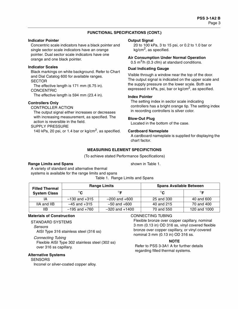
Range Limits and SpansA variety of standard and alternative thermal systems is available for the range limits and spans
shown in Table 1.
Materials of Construction
STANDARD SYSTEMSSensors
AISI Type 316 stainless steel (316 ss)
Connecting TubingFlexible AISI Type 302 stainless steel (302 ss) over 316 ss capillary.
Alternative SystemsSENSORS
Inconel or silver-coated copper alloy.
CONNECTING TUBINGFlexible bronze over copper capillary, nominal 3 mm (0.13 in) OD 316 ss, vinyl covered flexible bronze over copper capillary, or vinyl covered nominal 3 mm (0.13 in) OD 316 ss.
NOTERefer to PSS 3-3A1 A for further details regarding filled thermal systems.
Table 1. Range Limits and Spans
Filled Thermal System Class
Range Limits Spans Available Between
°C °F °C °F
IA –130 and +315 –200 and +600 25 and 330 40 and 600IIA and IIB –45 and +315 –50 and +600 40 and 215 70 and 400
IIB –195 and +760 –320 and +1400 70 and 550 120 and 1000
PSS 3-1A2 BPage 4
PHYSICAL SPECIFICATIONS
EnclosureThe case and door are glass-fiber reinforced polyester moldings, compounded for superior corrosion resistance. The door has a shatterproof glass window. The overall construction meets IEC IP53 and provides the environmental protection of NEMA Type 3.
Approximate Mass (Excluding Element)RECORDERS AND INDICATORS
11 kg (24 lb)CONTROLLERS
13 kg (28 lb)
Flammability RatingThe case and door meet Type V-O of UL94: (Underwriters Laboratory Incorporated Standard for Test Flammability of Plastic Materials, UL94),
FinishCase is gray polyester and door is blue textured (either epoxy powder coating or baked vinyl).
Data LabelAluminum data label fastened to chart plate with pressure sensitive adhesive. Includes space for customer tag data up to a maximum of 110 characters and spaces. For additional space, see optional Customer Tag.
OPTIONAL FEATURES
Inlet Purge RestrictorConnection tapped for 1/4 NPT fittings (AS Reference IPR).
Nameplate
Laminated plastic nameplates 38 x76 mm (1.5 x 3 in) with white characters on a black background. Maximum of 5 lines with 28 characters or spaces 3 mm (0.13 in) high or 24 characters or spaces 4 mm (0.16 in) high per line (AS Reference N/P).
Customer TagStainless steel tag wired to instrument for customer tag data that does not fit on data plate. There can be a maximum of 10 lines of data with 40 characters and spaces per line. Specify AS Code MTS.
Flush Door Lock
With 2 keys (AS Reference FDL).
Internal IlluminationAn incandescent lamp is available for operation from a nominal 120 or 240 V ac power source, as specified (AS Reference II-I).
Pipe MountingA kit of parts is available for mounting the instrument on a DN 50 or 2 in vertical pipe.
Type 70 Electric ContactsA variety of contact systems is available to provide a wide range of switching functions to actuate external control or alarm circuits. Refer to Technical Information (TI) 33-10a.
Fiber Tip PenFor Dual, Duplex, and Auto-Selector Controllers only. (Note that this pen is a standard selection using Model Code for a Recorder or Single Action Recording Controller.) Standard box-type pen can be replaced with fiber-tip pen with disposable ink cartridge. Minimum of 365 m (1200 ft) ink line at a nominal 25 mm/s (1 in/s) chart speed. Specify Auxiliary Specification Code (AS Code) PN-FT.
Recorder Chart DrivesPNEUMATIC, SINGLE SPEED
One revolution in 24 hoursPNEUMATIC, TWO SPEED
One revolution in 24 hours or 7 days.ELECTRICAL, SINGLE SPEED
One revolution in 1, 2, 4, 6, 7.5, 12, 15, 24, or 30 minutes; 1, 2, 3, 4, 6, 8, or 12 hours; or 2, 3, 4, 7, or 31 days.
ELECTRICAL, TWO SPEEDAny combination of two of the following speeds: One revolution in 30 seconds; 1, 5, 6, 12, 24 or 30 minutes; 1, 4, 8, 12, or 24 hours; 2, 3, or 7 days.
MECHANICAL, SINGLE SPEEDOne revolution in 8 or 12 hours with 24-hour movement; 24 or 48 hours with 7-day movement; 8 days with 8-day movement; 7 days with a 7-day movement; or 31 days with a 31-day movement.
MECHANICAL, TWO SPEEDOne revolution in 7 days/24hours with 7-day movement; or 8 days/24hours with 8-day movement.
PSS 3-1A2 BPage 5
OPTIONAL FEATURES (CONT.)
Controllers OnlyTRANSFER SWITCH AND SUPPLY REGULATOR ARRANGEMENTS
Four basic arrangements are available; Internal supply regulator only; two-position nozzle seal switch only; internal supply regulator with two-position nozzle seal switch; and internal subpanel with an output regulator and a balance indicator and two-position A/M switch (right or left).
EXTERNAL MANUAL SET KNOBA knob which engages with the set point adjustment mechanism is fitted on the door (AS Reference OCS).
EXTERNAL CONNECTION TO INTEGRAL (RESET) BELLOWS
Used when an external feedback signal must be applied to prevent integral circuit saturation (AS Reference FSM).
“BATCH” FUNCTION ATTACHMENTFor processes involving discontinuous control, the integral function is modified to prevent overshoot and to initiate immediate corrective action when control is resumed.
PNEUMATICSET ATTACHMENTEnables the set point to be positioned pneumatically. Available over the full span or part of the span.
RATIO ATTACHMENTProvides manual means for setting the ratio between an uncontrolled variable (primary) and a controlled variable (secondary). The ratio is adjustable between 0.5:1 and 1.7:1 for square-root scales, or between 0.3:1 and 3:1 for uniform scales.
RELATION ATTACHMENTMaintains a fixed manually adjustment difference between an uncontrolled variable (primary) and a controlled variable (secondary). The relation is adjustable between 0 and ±50% of span (AS Reference RELATION).
PSS 3-1A2 BPage 6
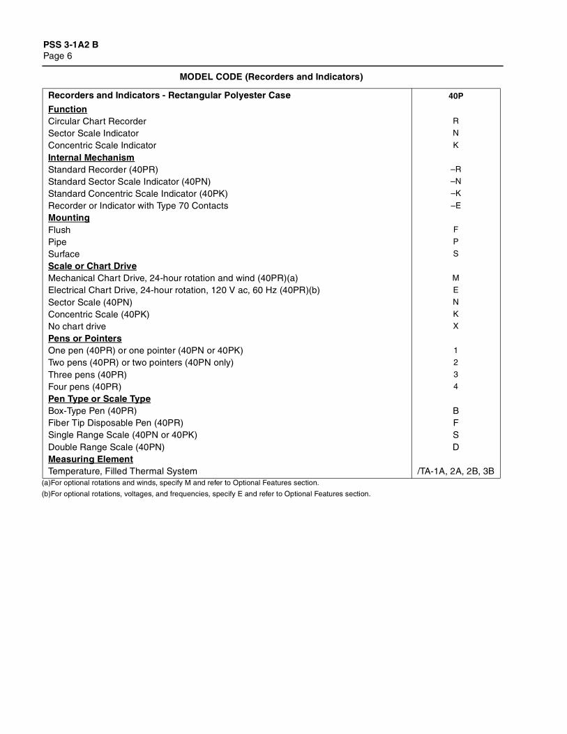
(a)For optional rotations and winds, specify M and refer to Optional Features section.
(b)For optional rotations, voltages, and frequencies, specify E and refer to Optional Features section.
MODEL CODE (Recorders and Indicators)
Recorders and Indicators - Rectangular Polyester Case 40P
FunctionCircular Chart Recorder R
Sector Scale Indicator N
Concentric Scale Indicator K
Internal MechanismStandard Recorder (40PR) –R
Standard Sector Scale Indicator (40PN) –N
Standard Concentric Scale Indicator (40PK) –K
Recorder or Indicator with Type 70 Contacts –E
MountingFlush F
Pipe P
Surface S
Scale or Chart DriveMechanical Chart Drive, 24-hour rotation and wind (40PR)(a) M
Electrical Chart Drive, 24-hour rotation, 120 V ac, 60 Hz (40PR)(b) E
Sector Scale (40PN) N
Concentric Scale (40PK) K
No chart drive X
Pens or PointersOne pen (40PR) or one pointer (40PN or 40PK) 1
Two pens (40PR) or two pointers (40PN only) 2
Three pens (40PR) 3
Four pens (40PR) 4
Pen Type or Scale TypeBox-Type Pen (40PR) BFiber Tip Disposable Pen (40PR) FSingle Range Scale (40PN or 40PK) SDouble Range Scale (40PN) DMeasuring ElementTemperature, Filled Thermal System /TA-1A, 2A, 2B, 3B
PSS 3-1A2 BPage 7
(a)For optional rotations and winds, specify M and refer to Optional Features section.
(b)For optional rotations, voltages, and frequencies, specify E and refer to Optional Features section.
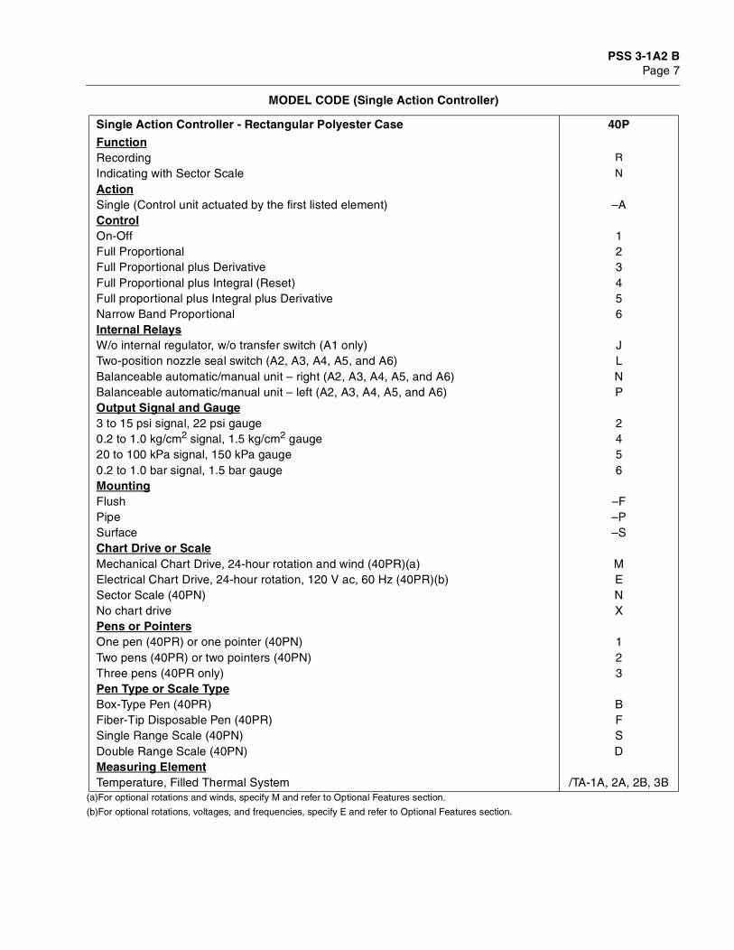
MODEL CODE (Single Action Controller)
Single Action Controller - Rectangular Polyester Case 40P
FunctionRecording R
Indicating with Sector Scale N
ActionSingle (Control unit actuated by the first listed element) –AControlOn-Off 1Full Proportional 2Full Proportional plus Derivative 3Full Proportional plus Integral (Reset) 4Full proportional plus Integral plus Derivative 5Narrow Band Proportional 6Internal RelaysW/o internal regulator, w/o transfer switch (A1 only) JTwo-position nozzle seal switch (A2, A3, A4, A5, and A6) LBalanceable automatic/manual unit – right (A2, A3, A4, A5, and A6) NBalanceable automatic/manual unit – left (A2, A3, A4, A5, and A6) POutput Signal and Gauge3 to 15 psi signal, 22 psi gauge 20.2 to 1.0 kg/cm2 signal, 1.5 kg/cm2 gauge 420 to 100 kPa signal, 150 kPa gauge 50.2 to 1.0 bar signal, 1.5 bar gauge 6MountingFlush –FPipe –PSurface –SChart Drive or ScaleMechanical Chart Drive, 24-hour rotation and wind (40PR)(a) MElectrical Chart Drive, 24-hour rotation, 120 V ac, 60 Hz (40PR)(b) ESector Scale (40PN) NNo chart drive XPens or PointersOne pen (40PR) or one pointer (40PN) 1Two pens (40PR) or two pointers (40PN) 2Three pens (40PR only) 3Pen Type or Scale TypeBox-Type Pen (40PR) BFiber-Tip Disposable Pen (40PR) FSingle Range Scale (40PN) SDouble Range Scale (40PN) DMeasuring ElementTemperature, Filled Thermal System /TA-1A, 2A, 2B, 3B
PSS 3-1A2 BPage 8
(a)Box-type pen is standard. For optionally available fiber tip pen, specify AS Reference PN-FT. See Optional Features section.
(b)For optional rotations and winds, specify M and refer to Optional Features section.
(c)For optional rotations, voltages, and frequencies, specify E and refer to Optional Features section.
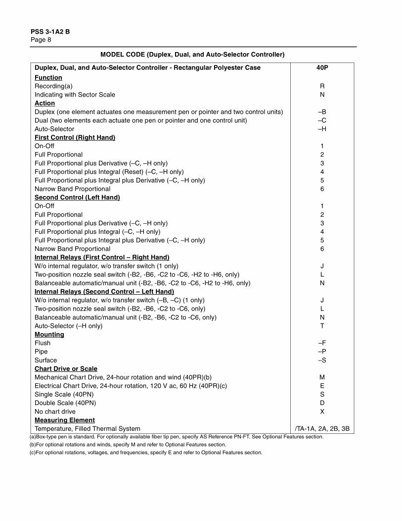
MODEL CODE (Duplex, Dual, and Auto-Selector Controller)
Duplex, Dual, and Auto-Selector Controller - Rectangular Polyester Case 40P
FunctionRecording(a) RIndicating with Sector Scale NActionDuplex (one element actuates one measurement pen or pointer and two control units) –BDual (two elements each actuate one pen or pointer and one control unit) –CAuto-Selector –HFirst Control (Right Hand)On-Off 1Full Proportional 2Full Proportional plus Derivative (–C, –H only) 3Full Proportional plus Integral (Reset) (–C, –H only) 4Full Proportional plus Integral plus Derivative (–C, –H only) 5Narrow Band Proportional 6Second Control (Left Hand)On-Off 1Full Proportional 2Full Proportional plus Derivative (–C, –H only) 3Full Proportional plus Integral (–C, –H only) 4Full Proportional plus Integral plus Derivative (–C, –H only) 5Narrow Band Proportional 6Internal Relays (First Control – Right Hand)W/o internal regulator, w/o transfer switch (1 only) JTwo-position nozzle seal switch (-B2, -B6, -C2 to -C6, -H2 to -H6, only) LBalanceable automatic/manual unit (-B2, -B6, -C2 to -C6, -H2 to -H6, only) NInternal Relays (Second Control – Left Hand)W/o internal regulator, w/o transfer switch (–B, –C) (1 only) JTwo-position nozzle seal switch (-B2, -B6, -C2 to -C6, only) LBalanceable automatic/manual unit (-B2, -B6, -C2 to -C6, only) NAuto-Selector (–H only) TMountingFlush –FPipe –PSurface –SChart Drive or ScaleMechanical Chart Drive, 24-hour rotation and wind (40PR)(b) MElectrical Chart Drive, 24-hour rotation, 120 V ac, 60 Hz (40PR)(c) ESingle Scale (40PN) SDouble Scale (40PN) DNo chart drive XMeasuring ElementTemperature, Filled Thermal System /TA-1A, 2A, 2B, 3B
PSS 3-1A2 BPage 9
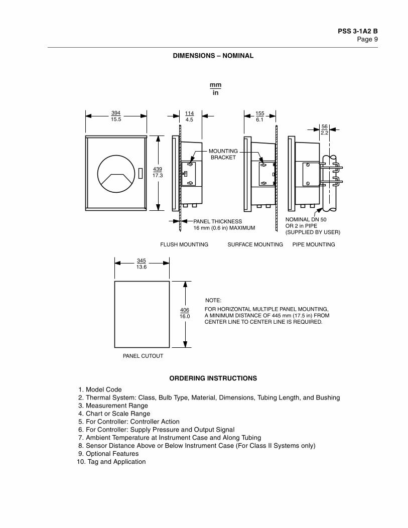
DIMENSIONS – NOMINAL
ORDERING INSTRUCTIONS
1. Model Code 2. Thermal System: Class, Bulb Type, Material, Dimensions, Tubing Length, and Bushing 3. Measurement Range 4. Chart or Scale Range 5. For Controller: Controller Action 6. For Controller: Supply Pressure and Output Signal 7. Ambient Temperature at Instrument Case and Along Tubing 8. Sensor Distance Above or Below Instrument Case (For Class II Systems only) 9. Optional Features10. Tag and Application
39415.5
43917.3
1144.5
34513.6
562.2
1556.1
40616.0
PANEL CUTOUT
FLUSH MOUNTING SURFACE MOUNTING
FOR HORIZONTAL MULTIPLE PANEL MOUNTING,A MINIMUM DISTANCE OF 445 mm (17.5 in) FROMCENTER LINE TO CENTER LINE IS REQUIRED.
NOTE:
PIPE MOUNTING
NOMINAL DN 50OR 2 in PIPE(SUPPLIED BY USER)
PANEL THICKNESS16 mm (0.6 in) MAXIMUM
MOUNTINGBRACKET

PSS 3-1A2 BPage 10

PSS 3-1A2 BPage 11
PSS 3-1A2 BPage 12
The Foxboro Company33 Commercial StreetFoxboro, MA 02035-2099United States of Americahttp://www.foxboro.comInside U.S.: 1-888-FOXBORO
(1-888-369-2676)Outside U.S.: Contact your local Foxboro representative.Facsimile (508) 549-4492
An Invensys company
Foxboro, HUMITEX, HYPER-RESET, and STABILOG are trademarks of The Foxboro Company.Invensys is a trademark of Invensys plc.All other brand names may be trademarks of their respective companies.
Copyright 1978-2001 The Foxboro CompanyAll rights reserved
MB 010 Printed in U.S.A. 0201

![[PSS 3-1A2 A] 40P Pressure Recorders, Indicators, and ...€¦ · 40P Series Pressure Recorders, Indicators, and Recording or Indicating Controllers ... tube measuring elements are](https://img.pdfslide.us/doc/110x75/5ac633517f8b9ae06c8e34cc/pss-3-1a2-a-40p-pressure-recorders-indicators-and-40p-series-pressure.jpg)
![[3104] Samhällskunskap, SAM - Skolverket...Social studies 1a2 SAMSAM01a2 Social studies 1a2 The course social studies 1a2 covers points 1–5 under the heading Aim of the subject,](https://img.pdfslide.us/doc/110x75/5f3860bd8cb5b531b06e290f/3104-samhllskunskap-sam-skolverket-social-studies-1a2-samsam01a2-social.jpg)
![[PSS 3-1A2 C] 40P Flow Recorders, Indicators, and Controllers€¦ · Product Specifications PSS 3-1A2 C 40P Flow Recorders, Indicators, and Controllers RECORDING CONTROLLER INDICATING](https://img.pdfslide.us/doc/110x75/5ac019bc7f8b9a433f8b5fb1/pss-3-1a2-c-40p-flow-recorders-indicators-and-controllers-product-specifications.jpg)


![[Tarot] El Libro de Thot - Manual Entero (40p)](https://img.pdfslide.us/doc/110x75/577d297a1a28ab4e1ea6e57f/tarot-el-libro-de-thot-manual-entero-40p.jpg)