Embed Size (px)
Citation preview
© Brüel & Kjaer Vibro ● S1077787.002 / V04 ● █ Page 1 of 19Technical alterations reserved!
Product specifications and ordering information VC-8000 Universal Monitoring Module - UMM
Overview
The VC-8000 Universal Monitoring Module (UMM) provides four channels of machinery monitoring. Each channel is individually configurable for nearly 50 different types of vibration, position, and speed measurements on rotating and reciprocating machinery (refer to page 2 for a comprehensive list of channel types and measurements returned).
The UMM occupies a single slot in a VC-8000 monitoring system rack and uses 24 Vdc instrument power as supplied by the VC-8000 Rack Connection Module (RCM). Each UMM provides all necessary transducer power, signal conditioning, alarm comparison, and relay logic functions needed to provide four channels of continuous machinery monitoring and shutdown protection. It complies with the requirements of American Petroleum Institute Standard 670 for monitoring systems and is completely configurable using VC-8000 configuration software. Up to 15 UMM cards can reside in a single 19” VC-8000 rack, providing up to 60 channels of continuous machinery protection. Each module provides basic status indication for its channels as required by API 670. When used with the optional rack touchscreen, real time display of vibration levels, alarm statuses, and other information is available for all channels concurrently on a single screen for “at a glance” convenience.
When ordered with optional condition monitoring capabilities, the module streams high-speed static and dynamic (i.e., waveform) data to the rack’s System Access Module (SAM) where it is available to software such as Setpoint® CMS and/or the rack’s embedded high-speed “flight recorder” on SD Card or Solid State Drive.
Page 2 of 19 █ © Brüel & Kjaer Vibro ● S1077787.002 / V04 Technical alterations reserved!
EN
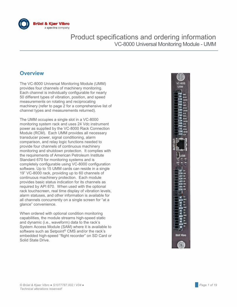
UMM Channel Types Part 1
Measurements Returned
Acc
eler
atio
n –
Aero
A
ccel
erat
ion
- Dia
gnos
tic
Acc
eler
atio
n –
Enve
lope
d A
ccel
erat
ion
– Lo
w F
req
A
ccel
erat
ion
– R
EB (n
orm
al)
Acc
eler
atio
n –
REB
(Slo
w)
Acc
el –
REB
Tra
ckin
g A
ccel
erat
ion
– R
MS
(Slo
w)
Acc
eler
atio
n –
Stan
dard
A
cous
tic
Gen
eric
Dyn
amic
R
adia
l Vib
– A
ir M
achi
ne
Rad
ial V
ib –
Dia
gnos
tic
Rad
ial V
ib –
Hyd
ro7
Rad
ial V
ib –
Sha
ft Ab
s2,6
Rad
ial V
ib –
Sha
ft R
el
Rad
ial V
ib –
SM
AX
REB
AM
Rod
Pos
ition
V
eloc
ity –
Dia
gnos
tic
Vel
ocity
– A
ero
Vel
ocity
– S
tand
ard
Vel
ocity
– L
ow F
req
Vel
ocity
– H
ydro
7 V
eloc
ity –
Rec
ip C
rank
V
eloc
ity –
Sha
ft Ab
s2,6
Overall (wideband) amplitude ● ● ●
Non
-trac
king
Ba
ndpa
ss F
ilter
ed
84 dB/octave roll-on/off 84 dB/oct roll-on & 72dB/oct roll-off 91 91 48 dB/octave roll-on/off 21 21 36 dB/octave roll-on/off 81 24 dB/octave roll-on/off ● 21 ● ● ● ● 21 21 ● ● 6 dB/octave roll-on/off 21 41 31 ● 31 ● ● ● Enveloped band 1 (cage) ● Enveloped band 2 (IRBP) ● Enveloped band 3 (ORBP) ● Enveloped band 4 (Ball Spin) ● Enveloped band 5 (2X Ball Spin) ●
Trac
king
Ve
ctor
Filt
ered
1X Amplitude - tracking vector filter PT PT PT PT PT PT PT PT PT PT PT PT PT PT PT PT 1X Phase - tracking vector filter PT PT PT PT PT PT PT PT PT PT PT PT PT
2X Amplitude - tracking vector filter PT PT PT PT PT PT PT PT PT PT 2X Phase - tracking vector filter PT PT PT PT PT PT PT
nX Amplitude - tracking vector filter PT PT PT PT PT PT PT
nX Phase - tracking vector filter PT PT PT PT PT PT
Cage - tracking vector filter PT
IRBP - tracking vector filter PT
ORBP - tracking vector filter PT Ball Spin - tracking vector filter PT
2X Ball Spin - tracking vector filter PT
4X Amplitude - tracking vector filter PT
Tracking 1X band (48 dB/oct) PT PT
Sensor DC Bias Voltage ● ● ● ● ● ● ● ● ● ● ● ● ● ● ● ● ● ●
High-Freq Demodulated PK Stretch ● ● ● Rotor Region ● Crank Angle ● Prime Spike ● ● ● SMAX ● Shaft absolute vibration ●
Rod Position Magnitude ●
Rod Position Phase ●
Probe 1 Gap Voltage ● ● ● ● ● ● ● Probe 2 Gap Voltage ●
© Brüel & Kjaer Vibro ● S1077787.002 / V04 ● █ Page 3 of 19 Technical alterations reserved!
Product specifications and ordering information Universal Monitoring Module EN
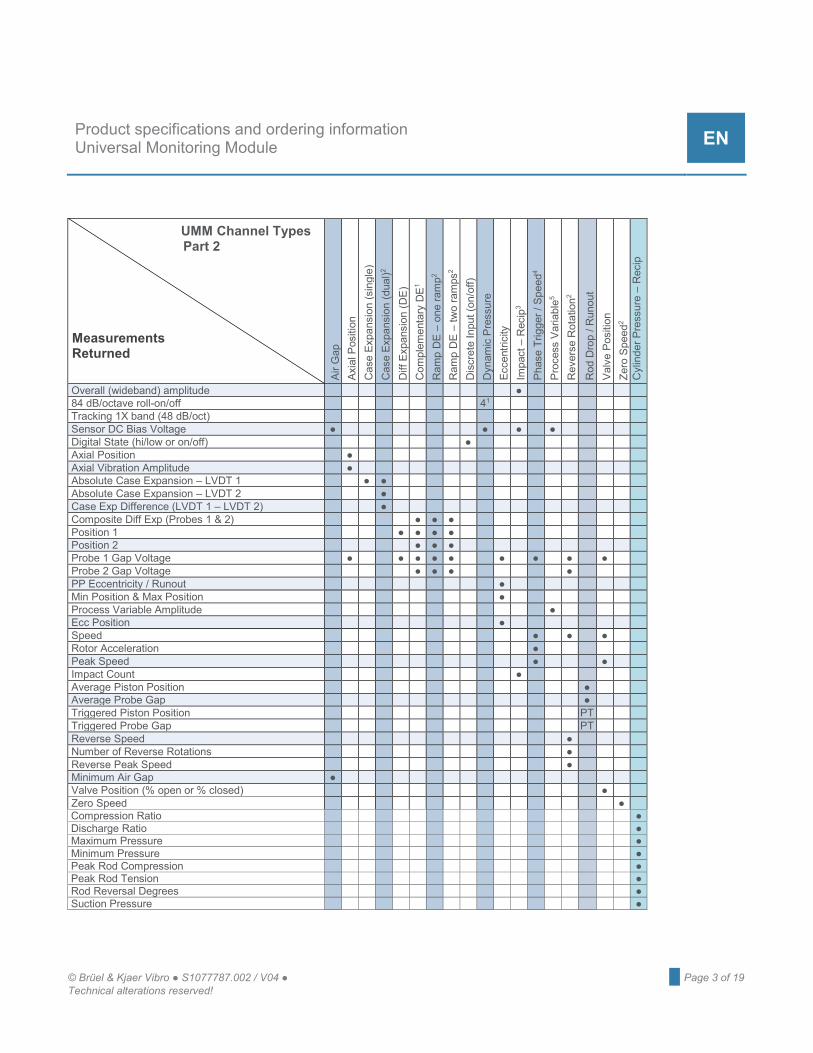
UMM Channel Types Part 2
Measurements Returned
Air
Gap
A
xial
Pos
ition
C
ase
Expa
nsio
n (s
ingl
e)
Cas
e Ex
pans
ion
(dua
l)2 D
iff E
xpan
sion
(DE)
C
ompl
emen
tary
DE1
Ram
p D
E –
one
ram
p2 R
amp
DE
– tw
o ra
mps
2 D
iscr
ete
Inpu
t (on
/off)
D
ynam
ic P
ress
ure
Ecc
entri
city
Im
pact
– R
ecip
3 P
hase
Trig
ger /
Spe
ed4
Pro
cess
Var
iabl
e5 R
ever
se R
otat
ion2
Rod
Dro
p / R
unou
t V
alve
Pos
ition
Z
ero
Spee
d2 C
ylin
der P
ress
ure
– R
ecip
Overall (wideband) amplitude ● 84 dB/octave roll-on/off 41 Tracking 1X band (48 dB/oct) Sensor DC Bias Voltage ● ● ● ● Digital State (hi/low or on/off) ● Axial Position ● Axial Vibration Amplitude ● Absolute Case Expansion – LVDT 1 ● ● Absolute Case Expansion – LVDT 2 ● Case Exp Difference (LVDT 1 – LVDT 2) ● Composite Diff Exp (Probes 1 & 2) ● ● ● Position 1 ● ● ● ● Position 2 ● ● ● Probe 1 Gap Voltage ● ● ● ● ● ● ● ● ● Probe 2 Gap Voltage ● ● ● ● PP Eccentricity / Runout ● Min Position & Max Position ● Process Variable Amplitude ● Ecc Position ● Speed ● ● ● Rotor Acceleration ● Peak Speed ● ● Impact Count ● Average Piston Position ● Average Probe Gap ● Triggered Piston Position PT Triggered Probe Gap PT Reverse Speed ● Number of Reverse Rotations ● Reverse Peak Speed ● Minimum Air Gap ● Valve Position (% open or % closed) ● Zero Speed ● Compression Ratio ● Discharge Ratio ● Maximum Pressure ● Minimum Pressure ● Peak Rod Compression ● Peak Rod Tension ● Rod Reversal Degrees ● Suction Pressure ●

Page 4 of 19 █ © Brüel & Kjaer Vibro ● S1077787.002 / V04 Technical alterations reserved!
EN
NOTES:
● Measurement always available. PT Measurement available only with a valid phase trigger signal; a single phase trigger can be
associated with multiple channels in a rack.
1 Denotes the number of individually configurable bandpass regions available for the channel. Any region can be configured with filter corners for wideband (i.e., “overall”) amplitude or narrowband measurements.
2 Denotes a measurement that uses two sensors and requires two UMM channels.
3 Seismic acceleration and velocity channels return a peak amplitude that is computed as peak-to-peak /2. However, recip impact channel types return a “true max” acceleration amplitude that is computed by first rectifying the signal and then detecting the peak. This amplitude detection method is unique to impact channels because the signal is almost always highly asymmetrical and pk-pk /2 will not give reliable results for setting impact count threshold levels.
4 Phase triggers may only be assigned to UMM channel 4 in rack slots 4-9. Maximum of 6 phase trigger per 16-P rack; 5 phase triggers per 8-P rack; 1 phase trigger per 4-P rack. Speed channels (no phase capabilities) can be configured for any UMM channels without restrictions.
5 UMM channels configured for process variable measurements are able to provide loop power and accept a wider variety of input signals than TMM channels. TMM channels accept 4-20mA input types only, do not provide loop power, and require an external shunt resistor. Refer to TMM datasheet S1077788 for additional information.
6 Shaft Absolute measurements use two transducers: a shaft-observing proximity probe and a casing-mounted velocity transducer. The shaft relative and casing absolute channels must reside on the same UMM. The shaft relative channel returns both shaft relative and shaft absolute parameters; the other channel returns casing absolute parameters. Shaft absolute parameters are computed as the vector combination of shaft relative displacement and integrated casing velocity (i.e., casing absolute displacement).
7 Hydro channels cannot be configured for machines with rotational speeds higher than 600 rpm.
Refer to VC-8000 manual S1079330 for comprehensive information on configurable channel types and data returned for each. Some measurements shown for a given channel type are optional; they may be left un-configured if desired.
© Brüel & Kjaer Vibro ● S1077787.002 / V04 ● █ Page 5 of 19 Technical alterations reserved!
Product specifications and ordering information Universal Monitoring Module EN
Features and Benefits
Simple, reliable, self-contained design reduces likelihood of failures from inter-module dependencies.
Highly reliable design utilizes just three transitional connectors from signal input to relay output – significantly reducing possible failure points in the critical machinery protection path.
Individually programmable 4-20 mA outputs – each of the four 4-20mA outputs on a UMM can be assigned to any parameter from any channel on that UMM.
Clear, intuitive labeling on both faceplate and removable connectors.
Individual SPDT electro-mechanical relays for each channel – can be voted with other channels whether in the same or different rack modules. SPDT = Single Pole, Double Throw
Convenient connection to all 4 channels of buffered signal outputs via innovative RJ45 connector (RJ45-to-BNC cables sold separately). Standard CAT5/6 cables can be used for long runs.
Flexible signal conditioning – each UMM channel can be individually configured from an available list of nearly 50 different channel types (see page 2); most channel types return multiple parameters, any or all of which can be used for alarming if desired.
Fewer channel pair constraints – A and B inputs for dual-voting axial position measurements can reside on separate UMM cards for increased reliability; XY probe pairs can reside on different rack modules as well.1
Up to six2 phase reference signals in a single rack – channel 4 of any UMM in rack slots 4-9 can be configured to accept a once-per-turn phase trigger signal. Speed (no phase capabilities) can be assigned to any UMM channel, without restrictions.
Distributed power regulation for improved reliability – each UMM converts its 24 Vdc input power to all regulated voltages needed by on-board processors and transducers, reducing the potential for rack single-point failures compared to systems that generate regulated voltages for the entire rack in a centralized power supply.
Powerful onboard processor delivers 24-bit A-to-D resolution for highly accurate measurements – no potentiometers, no drift, no calibration required.
Digital MODBUS® communications via System Access Module (SAM) can be used in lieu of (or simultaneously with) analog 4-20 mA outputs for flexibility when integrating with other instrumentation.
Unparalleled ease of configuration via VC-8000 configuration software’s intuitive spreadsheet-like user interface – easily cut and paste to/from Microsoft® Excel® and most other programs.
Provides loop power for process variable transmitters. Non-vibration signals from process transmitters and other devices providing ±4 to ±20 mA, +1 to +5 Vdc, 0 to ±10 Vdc, and 0 to +5 Vdc proportional signals can be easily included in the VC-8000 system for display, alarming, and trending. For 4-20mA loop-powered input devices, the UMM can be configured to provide +24V, eliminating the need for external loop power.
1. Depending on relay and channel voting complexity, XY probe pairs on the same UMM can improve the total amount of relay voting logic allowed in a rack.
2. Half-size rack limited to 5 phase reference inputs (slots 4-8). Quarter-size rack limited to 1 phase reference input (slot 4).
Page 6 of 19 █ © Brüel & Kjaer Vibro ● S1077787.002 / V04 Technical alterations reserved!
EN
Simplified spare parts requirements. Because every measurement in the VC-8000 system is made with just two module types (UMMs and TMMs), only two monitoring types need to be carried as spares. For systems without temperature measurements, only a single monitoring module type is used.
No jumpers or DIP switches. Every option in the VC-8000 system is configured via software. Cards do not have to be removed from the rack.
Connectivity to condition monitoring software. When ordered with condition monitoring enabled, a UMM becomes a UMM-CM and is able to stream high-resolution waveforms to the rack’s System Access Module (SAM) where it can be stored on an embedded “flight recorder” hard drive and/or SD Card, or to an external computer or OSIsoft® PI System server. The data can then be viewed with our Setpoint® CMS Display software.
SIL-Capable Architecture VC-8000 is suitable for use as part of a SIS, to implement safety instrumented functions up to SIL 2 when configured, installed and commissioned properly as per instructions provided within the Operations and Maintenance Manual (S1079330) and safety manuals (C107577, C107576, C107578, C107579). Highly Flexible Rack Control The UMM discrete channel type can be used not only to accept and display discrete on/off type signals, but to control rack states such as trip multiply, bypass, inhibit, etc. When invoked from the wiring terminals on the RCM, these control states are applied rack wide. When invoked using UMM discrete input channels, these states can be individually applied to user-configurable groups, facilitating better control when multiple machine trains are combined in a rack, each with its own unique trip multiply, bypass, inhibit, and other control needs.
© Brüel & Kjaer Vibro ● S1077787.002 / V04 ● █ Page 7 of 19 Technical alterations reserved!
Product specifications and ordering information Universal Monitoring Module EN
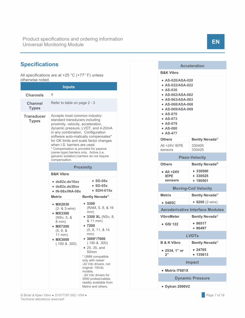
Specifications
All specifications are at +25 °C (+77° F) unless otherwise noted.
Inputs
Channels 4
Channel Types
Refer to table on page 2 - 3
Transducer Types
Accepts most common industry-standard transducers including proximity, velocity, acceleration, dynamic pressure, LVDT, and 4-20mA in any combination. Configuration software auto-matically compensates* for OK limits and scale factor changes when I.S. barriers are used. * Compensation is provided for passive (zener-type) barriers only. Active (i.e. galvanic isolation) barriers do not require compensation.
Proximity B&K Vibro
ds82x.ds10xx ds82x.ds30xx IN-08x/INA-08x
SD-08x SD-05x SDH-015x
Metrix Bently Nevada®
MX2030 (2- & 3-wire)
MX3300 (NSv, 5, & 8 mm)
MX7200 (5, 8, & 11 mm)
MX3000 (.190 & .300)
3300 (RAM, 5, 8, & 16 mm)
3300 XL (NSv, 8, & 11 mm)
7200 (5, 8, 11, & 14 mm)
3000*/7000 (.190 & .300)
25, 35, and 50mm
* UMM compatible only with newer -24 Vdc drivers, not original -18Vdc models. -24 Vdc drivers for 3000 probes/cables readily available from Metrix and others.
Acceleration B&K Vibro
AS-020/ASA-020 AS-022/ASA-022 AS-030 AS-062/ASA-062 AS-063/ASA-063 AS-068/ASA-068 AS-069/ASA-069 AS-070 AS-073 AS-079 AS-080 AS-477
Others Bently Nevada® All +24V IEPE sensors
330400 330425
Piezo-Velocity Others Bently Nevada®
All +24V IEPE sensors
330500 330525 190501
Moving-Coil Velocity Metrix Bently Nevada®
5485C 9200 (2-wire)
Aeroderivative Interface Modules VibroMeter Bently Nevada®
GSI 122 86517 86497
LVDTs B & K Vibro Bently Nevada®
2534, 1” or 2”
24765 135613
Impact
Metrix IT681X
Dynamic Pressure
Dytran 2006V2
Page 8 of 19 █ © Brüel & Kjaer Vibro ● S1077787.002 / V04 Technical alterations reserved!
EN
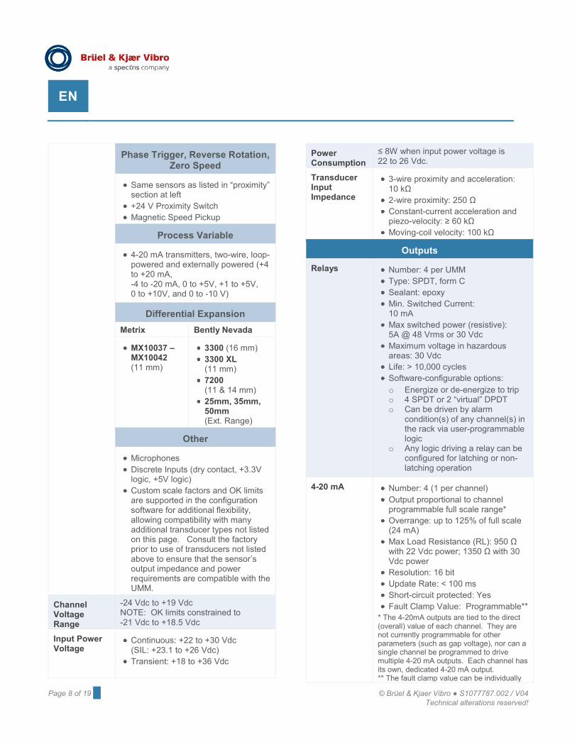
Phase Trigger, Reverse Rotation, Zero Speed
Same sensors as listed in “proximity” section at left
+24 V Proximity Switch Magnetic Speed Pickup
Process Variable
4-20 mA transmitters, two-wire, loop-powered and externally powered (+4 to +20 mA, -4 to -20 mA, 0 to +5V, +1 to +5V, 0 to +10V, and 0 to -10 V)
Differential Expansion Metrix Bently Nevada
MX10037 – MX10042 (11 mm)
3300 (16 mm) 3300 XL (11 mm)
7200 (11 & 14 mm)
25mm, 35mm, 50mm (Ext. Range)
Other
Microphones Discrete Inputs (dry contact, +3.3V logic, +5V logic)
Custom scale factors and OK limits are supported in the configuration software for additional flexibility, allowing compatibility with many additional transducer types not listed on this page. Consult the factory prior to use of transducers not listed above to ensure that the sensor’s output impedance and power requirements are compatible with the UMM.
Channel Voltage Range
-24 Vdc to +19 Vdc NOTE: OK limits constrained to -21 Vdc to +18.5 Vdc
Input Power Voltage
Continuous: +22 to +30 Vdc (SIL: +23.1 to +26 Vdc)
Transient: +18 to +36 Vdc
Power Consumption
≤ 8W when input power voltage is 22 to 26 Vdc.
Transducer Input Impedance
3-wire proximity and acceleration: 10 kΩ
2-wire proximity: 250 Ω Constant-current acceleration and piezo-velocity: ≥ 60 kΩ
Moving-coil velocity: 100 kΩ
Outputs
Relays Number: 4 per UMM Type: SPDT, form C Sealant: epoxy Min. Switched Current: 10 mA
Max switched power (resistive): 5A @ 48 Vrms or 30 Vdc
Maximum voltage in hazardous areas: 30 Vdc
Life: > 10,000 cycles Software-configurable options: o Energize or de-energize to trip o 4 SPDT or 2 “virtual” DPDT o Can be driven by alarm
condition(s) of any channel(s) in the rack via user-programmable logic
o Any logic driving a relay can be configured for latching or non-latching operation
4-20 mA Number: 4 (1 per channel) Output proportional to channel programmable full scale range*
Overrange: up to 125% of full scale (24 mA)
Max Load Resistance (RL): 950 Ω with 22 Vdc power; 1350 Ω with 30 Vdc power
Resolution: 16 bit Update Rate: < 100 ms Short-circuit protected: Yes Fault Clamp Value: Programmable**
* The 4-20mA outputs are tied to the direct (overall) value of each channel. They are not currently programmable for other parameters (such as gap voltage), nor can a single channel be programmed to drive multiple 4-20 mA outputs. Each channel has its own, dedicated 4-20 mA output. ** The fault clamp value can be individually
© Brüel & Kjaer Vibro ● S1077787.002 / V04 ● █ Page 9 of 19 Technical alterations reserved!
Product specifications and ordering information Universal Monitoring Module EN
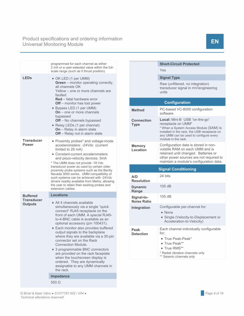
programmed for each channel as either 2 mA or a user-selected value within the full-scale range (such as 0 thrust position).
LEDs OK LED (1 per UMM) Green – monitor operating correctly, all channels OK Yellow – one or more channels are faulted Red – fatal hardware error Off – monitor has lost power
Bypass LED (1 per UMM) On – one or more channels bypassed Off – No channels bypassed
Relay LEDs (1 per channel) On – Relay in alarm state Off – Relay not in alarm state
Transducer Power
Proximity probes* and voltage-mode accelerometers: -24Vdc (current limited to 25 mA)
Constant-current accelerometers and piezo-velocity devices: 3mA
* The UMM does not provide -18 Vdc transducer power as used by certain older proximity probe systems such as the Bently Nevada 3000 series. UMM compatibility of such systems can be achieved with -24Vdc drivers readily available from Metrix, allowing the user to retain their existing probes and extension cables.
Buffered Transducer Outputs
Locations
All 4 channels available simultaneously via a single “quick connect” RJ45 receptacle on the front of each UMM. A special RJ45-to-4-BNC cable is available as an optional accessory (p/n 100431).
Each monitor also provides buffered output signals to the backplane where they are available via a 30-pin connector set on the Rack Connection Module.
3 programmable BNC connectors are provided on the rack faceplate when the touchscreen display is ordered. They are dynamically assignable to any UMM channels in the rack.
Impedance 550 Ω
Short-Circuit Protected Yes
Signal Type Raw (unfiltered, no integration) transducer signal in mV/engineering units
Configuration
Method PC-based VC-8000 configuration software
Connection Type
Local: Mini-B USB “on-the-go” receptacle on UMM* * When a System Access Module (SAM) is installed in the rack, the USB receptacle on any UMM can be used to configure every module in the rack.
Memory Location
Configuration data is stored in non-volatile RAM on each UMM and is retained until changed. Batteries or other power sources are not required to maintain a module’s configuration data.
Signal Conditioning
A/D Resolution
24 bits
Dynamic Range
105 dB
Signal-to-Noise Ratio
105 dB
Integration Configurable per-channel for: None Single (Velocity-to-Displacement or Acceleration-to-Velocity)
Peak Detection
Each channel individually configurable for:
True Peak-Peak* True Peak** True RMS**
* Radial vibration channels only ** Seismic channels only

Page 10 of 19 █ © Brüel & Kjaer Vibro ● S1077787.002 / V04 Technical alterations reserved!
EN
Accuracy Vibration / Position Channels Direct
Typical: ± 0.3% of full scale Minimum: ± 1% of full scale
Gap / Bias
Typical: ± 0.07 V Minimum: ± 0.24 V
Speed / Phase Channels Phase: ± 1 degree Speed:
1 - 30 rpm: ± 0.1 rpm 30 - 7,500 rpm: ± 1 rpm 7,500 - 60,000 rpm: ± 0.1% 60 - 100 krpm: ± 0.2%
Speed/Phase Channel Settings
Threshold: Configurable for Auto or Manual
Manual Threshold Range: +18 to -22 V
Hysteresis: 0.2 to 2.5 V in 0.1 V increments
NOTES: 1. The speed/phase channel type is
compatible with proximity probes, magnetic pickups, and proximity switches. For phase measurements, proximity probes are recommended.
2. Speed/phase channel types are configurable for single or multiple events per revolution. Non integer values can be entered in the channel configuration settings to accommodate compound gear arrangements and complex ratios.
3. A multiple event per revolution target (such as a toothed wheel) is not recommended for phase readings. The tooth for which the system triggers will be arbitrarily selected from one machine run to the next and will not allow consistent phase readings if the phase trigger signal is interrupted and then reestablished, such as when shutting the machine down and restarting or correcting a wiring problem.
Radial Vibration Channel Filters
Direct
Type: Band pass Rollon/Rolloff: 6 dB/octave, 84 dB/octave roll-on & 72 dB/octave roll-off (hydro)
- 3 dB Passband: Configurable for 4 Hz to 4000 Hz or 1 Hz to 600 Hz
Gap
Type: Low pass Rolloff: 6 dB/octave -3 dB corner: 0.09 Hz
Fault / NOT OK
Type: Low pass Rolloff: 6 dB/octave -3 dB corner: 2.4 kHz
Axial Position Channel Filters
Direct
Type: Low pass Rolloff: 6 dB/octave -3 dB corner: 1.2 Hz
Gap
Type: Low pass, Rolloff: 6 dB/octave -3 dB corner: 0.41 Hz
© Brüel & Kjaer Vibro ● S1077787.002 / V04 ● █ Page 11 of 19 Technical alterations reserved!
Product specifications and ordering information Universal Monitoring Module EN
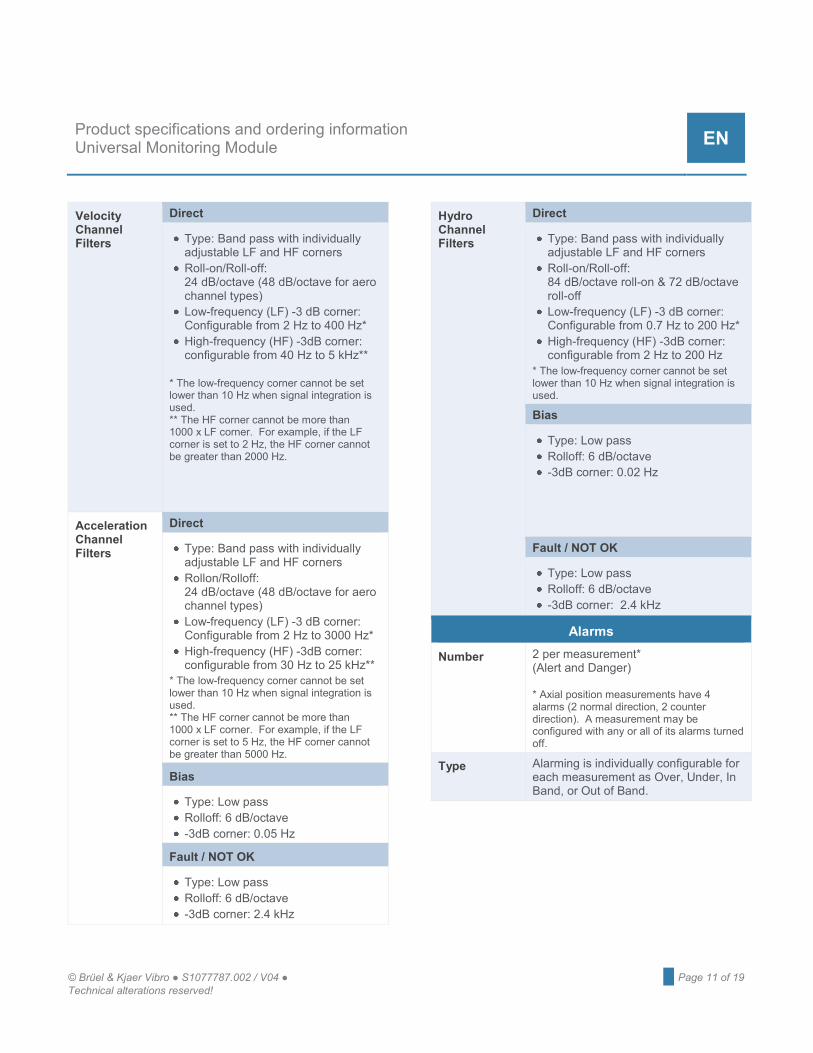
Velocity Channel Filters
Direct
Type: Band pass with individually adjustable LF and HF corners
Roll-on/Roll-off: 24 dB/octave (48 dB/octave for aero channel types)
Low-frequency (LF) -3 dB corner: Configurable from 2 Hz to 400 Hz*
High-frequency (HF) -3dB corner: configurable from 40 Hz to 5 kHz**
* The low-frequency corner cannot be set lower than 10 Hz when signal integration is used. ** The HF corner cannot be more than 1000 x LF corner. For example, if the LF corner is set to 2 Hz, the HF corner cannot be greater than 2000 Hz.
Acceleration Channel Filters
Direct
Type: Band pass with individually adjustable LF and HF corners
Rollon/Rolloff: 24 dB/octave (48 dB/octave for aero channel types)
Low-frequency (LF) -3 dB corner: Configurable from 2 Hz to 3000 Hz*
High-frequency (HF) -3dB corner: configurable from 30 Hz to 25 kHz**
* The low-frequency corner cannot be set lower than 10 Hz when signal integration is used. ** The HF corner cannot be more than 1000 x LF corner. For example, if the LF corner is set to 5 Hz, the HF corner cannot be greater than 5000 Hz.
Bias
Type: Low pass Rolloff: 6 dB/octave -3dB corner: 0.05 Hz
Fault / NOT OK
Type: Low pass Rolloff: 6 dB/octave -3dB corner: 2.4 kHz
Hydro Channel Filters
Direct
Type: Band pass with individually adjustable LF and HF corners
Roll-on/Roll-off: 84 dB/octave roll-on & 72 dB/octave roll-off
Low-frequency (LF) -3 dB corner: Configurable from 0.7 Hz to 200 Hz*
High-frequency (HF) -3dB corner: configurable from 2 Hz to 200 Hz
* The low-frequency corner cannot be set lower than 10 Hz when signal integration is used. Bias
Type: Low pass Rolloff: 6 dB/octave -3dB corner: 0.02 Hz
Fault / NOT OK
Type: Low pass Rolloff: 6 dB/octave -3dB corner: 2.4 kHz
Alarms
Number 2 per measurement* (Alert and Danger) * Axial position measurements have 4 alarms (2 normal direction, 2 counter direction). A measurement may be configured with any or all of its alarms turned off.
Type Alarming is individually configurable for each measurement as Over, Under, In Band, or Out of Band.
Page 12 of 19 █ © Brüel & Kjaer Vibro ● S1077787.002 / V04 Technical alterations reserved!
EN
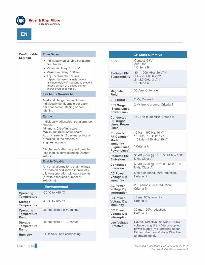
Configurable Settings
Time Delay
Individually adjustable per alarm, per channel.
Minimum Delay: 100 ms* Maximum Delay: 100 sec Adj. Increments: 100 ms * Speed / phase channels have a minimum delay of 1 second to prevent misuse as part of a speed control and/or overspeed circuit.
Latching / Non-latching
Alert and Danger setpoints are individually configurable per alarm, per channel for latching or non-latching
Range Individually adjustable, per alarm, per channel Minimum: 0% of full scale Maximum: 100% of full scale* Adj. increments: 2 decimal points of precision, in the channel’s engineering units * A channel’s Alert setpoint must be less than its corresponding Danger setpoint.
Enable/Disable Any or all alarms for a channel may be enabled or disabled individually, allowing operation without setpoints (or with a reduced number of setpoints).
Environmental
Operating Temperature
-20 °C to +65 °C
Storage Temperature
-40 °C to +85 °C
Operating Temperature Ramp
Do not exceed 0.5C/minute
Storage Temperature Ramp
Do not exceed 10C/minute
Humidity 5% to 95%, non-condensing
CE Mark Directive
ESD Contact: 6 kV* Air: 8 kV * Criteria B
Radiated EMI Susceptibility
80 – 1000 MHz: 20 V/m* 1.4 – 2 GHz: 6 V/m* 2 – 2.7 GHz: 3 V/m* * Criteria A
Magnetic Field
30 A/m, Criteria A
EFT Burst 2 kV, Criteria B
EFT Surge (Signal Lines, Power Line)
2 kV line to ground, Criteria B
Conducted RFI (Signal Lines, Power Lines)
150 kHz to 80 MHz, Criteria A
Conducted RF Common Mode Immunity (Signal Lines, Power Lines)
15 Hz – 150 Hz: 10 V* 150 Hz – 1.5 kHz: 1V* 1.5 kHz – 150 kHz: 10 V* * Criteria A
Radiated EMI Emissions
30 dB µV/m @ 30 m, 30 MHz – 1000 MHz, Class A
Conducted Emission
60 dB µV/m @ 30 m, 0.5 MHz – 30 MHz, Class A
AC Power Voltage Dip Immunity
One-half period, 30% reduction, Criteria B
AC Power Voltage Dip Interruption
250 periods, 95% reduction, Criteria B
DC Power Voltage Dip Immunity
10 ms, 60% reduction, Criteria B
DC Power Voltage Dip Interruption
30 ms, 100% reduction, Criteria B
Low Voltage Directive
Council Directive 2014/35/EU Low voltage using B & K Vibro-supplied power supply (rack ordering option –CC) or other Low Voltage Directive approved supply.
© Brüel & Kjaer Vibro ● S1077787.002 / V04 ● █ Page 13 of 19 Technical alterations reserved!
Product specifications and ordering information Universal Monitoring Module EN
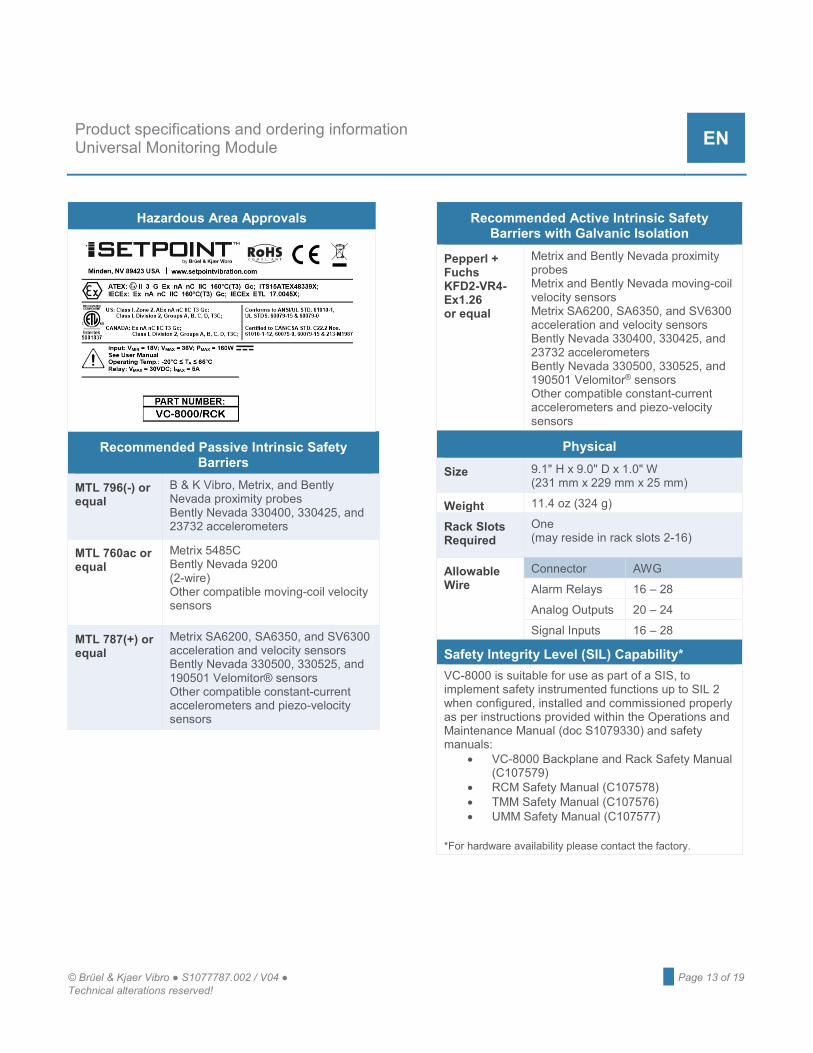
Hazardous Area Approvals
Recommended Passive Intrinsic Safety Barriers
MTL 796(-) or equal
B & K Vibro, Metrix, and Bently Nevada proximity probes Bently Nevada 330400, 330425, and 23732 accelerometers
MTL 760ac or equal
Metrix 5485C Bently Nevada 9200 (2-wire) Other compatible moving-coil velocity sensors
MTL 787(+) or equal
Metrix SA6200, SA6350, and SV6300 acceleration and velocity sensors Bently Nevada 330500, 330525, and 190501 Velomitor® sensors Other compatible constant-current accelerometers and piezo-velocity sensors
Recommended Active Intrinsic Safety Barriers with Galvanic Isolation
Pepperl + Fuchs KFD2-VR4-Ex1.26 or equal
Metrix and Bently Nevada proximity probes Metrix and Bently Nevada moving-coil velocity sensors Metrix SA6200, SA6350, and SV6300 acceleration and velocity sensors Bently Nevada 330400, 330425, and 23732 accelerometers Bently Nevada 330500, 330525, and 190501 Velomitor® sensors Other compatible constant-current accelerometers and piezo-velocity sensors
Physical
Size 9.1" H x 9.0" D x 1.0" W (231 mm x 229 mm x 25 mm)
Weight 11.4 oz (324 g)
Rack Slots Required
One (may reside in rack slots 2-16)
Allowable Wire
Connector AWG
Alarm Relays 16 – 28
Analog Outputs 20 – 24
Signal Inputs 16 – 28
Safety Integrity Level (SIL) Capability* VC-8000 is suitable for use as part of a SIS, to implement safety instrumented functions up to SIL 2 when configured, installed and commissioned properly as per instructions provided within the Operations and Maintenance Manual (doc S1079330) and safety manuals:
• VC-8000 Backplane and Rack Safety Manual (C107579)
• RCM Safety Manual (C107578) • TMM Safety Manual (C107576) • UMM Safety Manual (C107577)
*For hardware availability please contact the factory.
Page 14 of 19 █ © Brüel & Kjaer Vibro ● S1077787.002 / V04 Technical alterations reserved!
EN
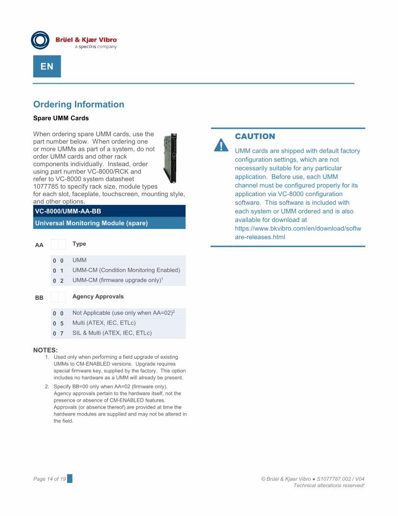
Ordering InformationSpare UMM Cards
When ordering spare UMM cards, use the part number below. When ordering one or more UMMs as part of a system, do not order UMM cards and other rack components individually. Instead, order using part number VC-8000/RCK and refer to VC-8000 system datasheet 1077785 to specify rack size, module types for each slot, faceplate, touchscreen, mounting style, and other options. VC-8000/UMM-AA-BB
Universal Monitoring Module (spare)
AA Type
0 0 UMM
0 1 UMM-CM (Condition Monitoring Enabled)
0 2 UMM-CM (firmware upgrade only)1
BB Agency Approvals
0 0 Not Applicable (use only when AA=02)2
0 5 Multi (ATEX, IEC, ETLc)
0 7 SIL & Multi (ATEX, IEC, ETLc)
NOTES: 1. Used only when performing a field upgrade of existing
UMMs to CM-ENABLED versions. Upgrade requires special firmware key, supplied by the factory. This option includes no hardware as a UMM will already be present.
2. Specify BB=00 only when AA=02 (firmware only). Agency approvals pertain to the hardware itself, not the presence or absence of CM-ENABLED features. Approvals (or absence thereof) are provided at time the hardware modules are supplied and may not be altered in the field.
CAUTION
UMM cards are shipped with default factory configuration settings, which are not necessarily suitable for any particular application. Before use, each UMM channel must be configured properly for its application via VC-8000 configuration software. This software is included with each system or UMM ordered and is also available for download at https://www.bkvibro.com/en/download/software-releases.html
!
© Brüel & Kjaer Vibro ● S1077787.002 / V04 ● █ Page 15 of 19 Technical alterations reserved!
Product specifications and ordering information Universal Monitoring Module EN
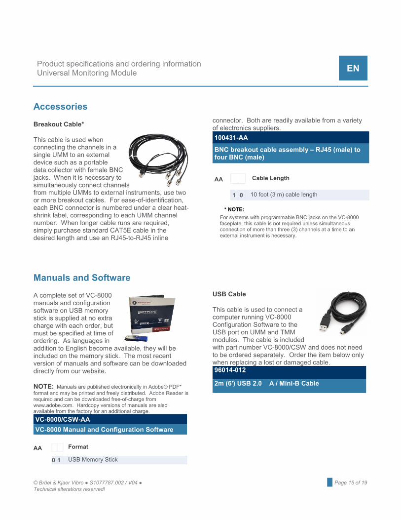
Accessories
Breakout Cable*
This cable is used when connecting the channels in a single UMM to an external device such as a portable data collector with female BNC jacks. When it is necessary to simultaneously connect channels from multiple UMMs to external instruments, use two or more breakout cables. For ease-of-identification, each BNC connector is numbered under a clear heat-shrink label, corresponding to each UMM channel number. When longer cable runs are required, simply purchase standard CAT5E cable in the desired length and use an RJ45-to-RJ45 inline
connector. Both are readily available from a variety of electronics suppliers. 100431-AA
BNC breakout cable assembly – RJ45 (male) to four BNC (male)
AA Cable Length
1 0 10 foot (3 m) cable length * NOTE:
For systems with programmable BNC jacks on the VC-8000 faceplate, this cable is not required unless simultaneous connection of more than three (3) channels at a time to an external instrument is necessary.
Manuals and Software
A complete set of VC-8000 manuals and configuration software on USB memory stick is supplied at no extra charge with each order, but must be specified at time of ordering. As languages in addition to English become available, they will be included on the memory stick. The most recent version of manuals and software can be downloaded directly from our website.
NOTE: Manuals are published electronically in Adobe® PDF* format and may be printed and freely distributed. Adobe Reader is required and can be downloaded free-of-charge from www.adobe.com. Hardcopy versions of manuals are also available from the factory for an additional charge. VC-8000/CSW-AA VC-8000 Manual and Configuration Software
AA Format
0 1 USB Memory Stick
USB Cable
This cable is used to connect a computer running VC-8000 Configuration Software to the USB port on UMM and TMM modules. The cable is included with part number VC-8000/CSW and does not need to be ordered separately. Order the item below only when replacing a lost or damaged cable. 96014-012
2m (6') USB 2.0 A / Mini-B Cable
Page 16 of 19 █ © Brüel & Kjaer Vibro ● S1077787.002 / V04 Technical alterations reserved!
EN
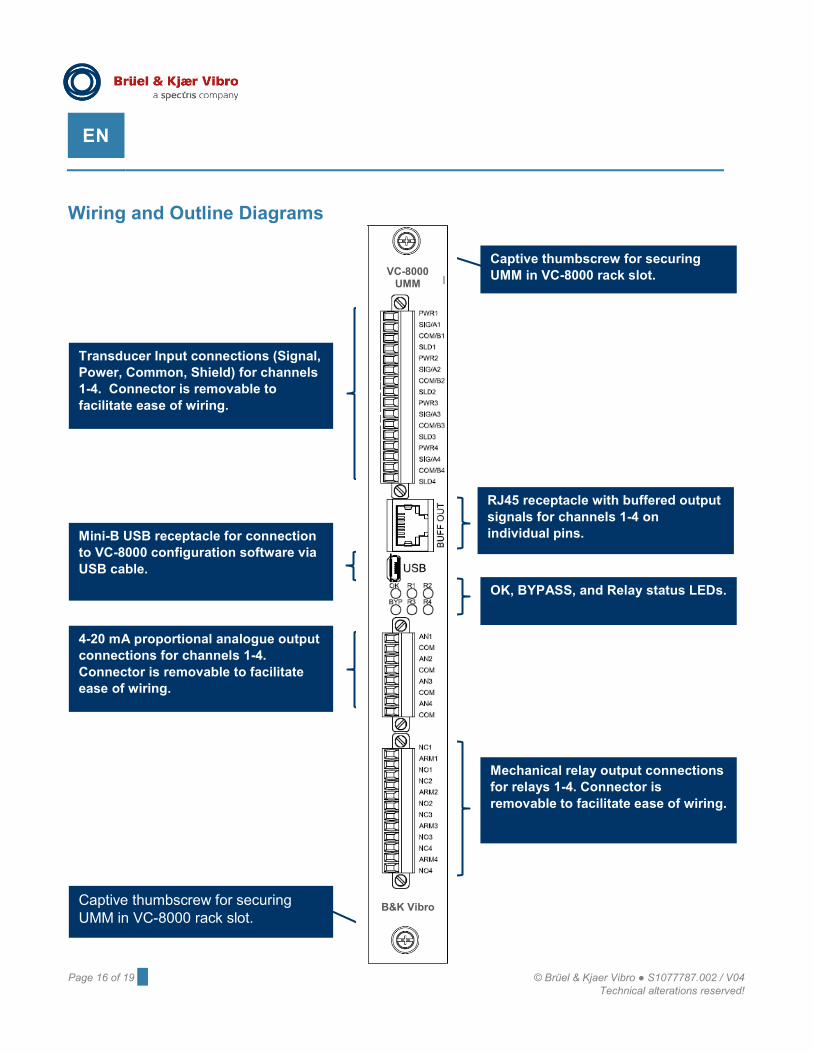
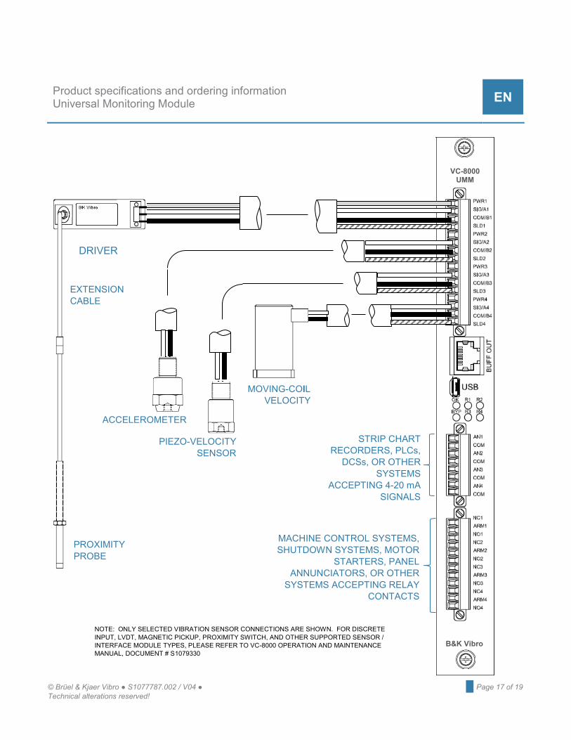
Wiring and Outline Diagrams
Transducer Input connections (Signal, Power, Common, Shield) for channels 1-4. Connector is removable to facilitate ease of wiring.
RJ45 receptacle with buffered output signals for channels 1-4 on individual pins.
Mini-B USB receptacle for connection to VC-8000 configuration software via USB cable.
OK, BYPASS, and Relay status LEDs.
4-20 mA proportional analogue output connections for channels 1-4. Connector is removable to facilitate ease of wiring.
Mechanical relay output connections for relays 1-4. Connector is removable to facilitate ease of wiring.
Captive thumbscrew for securing UMM in VC-8000 rack slot.
Captive thumbscrew for securing UMM in VC-8000 rack slot.
B&K Vibro
VC-8000 UMM
© Brüel & Kjaer Vibro ● S1077787.002 / V04 ● █ Page 17 of 19 Technical alterations reserved!
Product specifications and ordering information Universal Monitoring Module EN
VC-8000 UMM
B&K Vibro
NOTE: ONLY SELECTED VIBRATION SENSOR CONNECTIONS ARE SHOWN. FOR DISCRETE INPUT, LVDT, MAGNETIC PICKUP, PROXIMITY SWITCH, AND OTHER SUPPORTED SENSOR / INTERFACE MODULE TYPES, PLEASE REFER TO VC-8000 OPERATION AND MAINTENANCE MANUAL, DOCUMENT # S1079330
DRIVER
EXTENSION CABLE
PROXIMITY PROBE
ACCELEROMETER
PIEZO-VELOCITY SENSOR
STRIP CHART RECORDERS, PLCs,
DCSs, OR OTHER SYSTEMS
ACCEPTING 4-20 mA SIGNALS
MOVING-COIL VELOCITY
MACHINE CONTROL SYSTEMS, SHUTDOWN SYSTEMS, MOTOR
STARTERS, PANEL ANNUNCIATORS, OR OTHER
SYSTEMS ACCEPTING RELAY CONTACTS
Page 18 of 19 █ © Brüel & Kjaer Vibro ● S1077787.002 / V04 Technical alterations reserved!
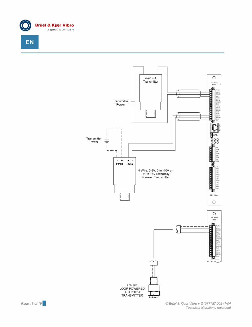
EN
VC-8000 UMM
VC-8000 UMM
B&K Vibro
Contact
BK Vibro America Inc. SETPOINT® Operations 2243 Park Place, Suite A Minden, Nevada 89423 USA Phone: +1 (775) 552 3110 E-Mail: [email protected] https://www.bkvibro.com/en/download/product-specifications-ordering-information.html
Brüel & Kjær Vibro GmbH Leydheckerstrasse 10 64293 Darmstadt Deutschland Phone: +49 (0) 6151 428 0 Fax: +49 (0) 6151 428 10 00 E-Mail: [email protected] www.bkvibro.com
Document S1077787.002 / V04 Trademarks used herein are the property of their respective owners. Data and specifications subject to change without notice. © 2011 - 2020


![2. Product specifications - Diagramas dediagramasde.com/diagramas/otros2/02_specifications[1].pdf · 2-1 2. Product specifications 2. Product specifications 2-1. Specifications Information](https://img.pdfslide.us/doc/110x75/5ac0f5e77f8b9ad73f8c5c3a/2-product-specifications-diagramas-1pdf2-1-2-product-specifications-2-product.jpg)