Embed Size (px)
Citation preview
Evacuated tube collectors
With galvanised steel installation systems
Product Specifications and Design Guide
ESC V6ESC V12ESC V18

• Collectors should be aligned such that they face south where possible.• Generally, the manifold is always to be installed uppermost.• A minimum slope of 15° is required for installation on roofs, as well as on flat roofs, to facilitate self-cleaning.• Do not remove the white protective sheet from the evacuated tubes until after the solar energy system hasbeen commissioned.
• In the solar circuit, use brazed joints or olive connections only.• Thermally insulate the pipes in accordance with the German Heating Installations Ordinance HeizAnlV. Ensure that the pipes are heat resistant (150°C) and UV resistant (pipes laid outdoors).
• Fill the solar energy system with “Tyfocor-LS” heat transfer medium only.• The evacuated tube collectors are hail resistant in accordance with DIN EN 12975-2. However, we recom-mend including storm and hail damage in your building insurance. Our materials guarantee does not coversuch damage.
• Work must comply with the relevant safety standards of DIN, DIN EN, DVGW, TRF and VDE.• Solar collectors require registration or permits in accordance with the corresponding valid state regulations.• Installation, maintenance and repairs must be carried out by authorised service personnel.• The pipework of the solar circuit in the lower part of the building must be bonded as specified by VDE . The solar energy system may only be connected to existing or new lightning protection systems or equipotential bonding by authorised service personnel.
The respective state’s specific standards and safety regulations must be adhered to. Carefully read through these planning instructions.
General information
ECOTHERM / 2011 ESC V6/ V12 / V18 design guide
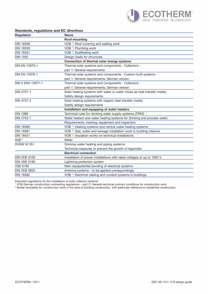
Standards, regulations and EC directivesRegulation Name Roof-mountingDIN 18338 VOB 1): Roof covering and sealing workDIN 18339 VOB 1): Plumbing workDIN 18451 VOB 1): Scaffolding workDIN 1055 Design loads for structures Connection of thermal solar energy systemsDIN EN 12975-1 Thermal solar systems and components - Collectors - part 1: General requirementsDIN EN 12976-1 Thermal solar systems and components - Custom-built systems - part 1: General requirements; German versionDIN V ENV 12977-1 Thermal solar systems and components - Collectors - part 1: General requirements; German versionDIN 4757-1 Solar heating systems with water or water mixes as heat transfer media; Safety design requirements DIN 4757-2 Solar heating systems with organic heat transfer media; Safety design requirements Installation and equipping of water heaters DIN 1988 Technical rules for drinking water supply systems (TRWI)DIN 4753-1 Water heaters and water heating systems for drinking and process water; Requirements, marking, equipment and inspection DIN 18380 VOB 1): Heating systems and central water heating systemsDIN 18381 VOB 1): Gas, water and sewage installation work in building interiorsDIN 18421 VOB 1): Insulation works on technical installationsAVB 2) WaterDVGW W 551 Drinking water heating and piping systems; Technical measures to prevent the growth of legionella Electrical connectionDIN VDE 0100 Installation of power installations with rated voltages of up to 1000 VDIN VDE 0185 Lightning protection systemVDE 0190 Main equipotential bonding of electrical systemsDIN VDE 0855 Antenna systems - to be applied correspondinglyDIN 18382 VOB 1): Electrical cabling and conduit systems in buildings
Important regulations for the installation of solar collector systems1) VOB German construction contracting regulations – part C: General technical contract conditions for construction work2) Tender templates for construction work in the area of building construction, with particular reference to residential construction
ECOTHERM / 2011 ESC V6/ V12 / V18 design guide
Intelligent design and installation:• Suitable for installation on pitched roofs, flat roofs, walls, free-standing and facade installation. • For heating drinking water and heating water for partial solar heating and swimming pool water, as well as for solar cooling.
• Great flexibility due to collector units of different widths.• Up to 15 m2 can be connected in series.• Exceptional design.• Quick installation thanks to completely pre-assembled collector units and simple, flexible on-roof and flat roof installation sets.
• Simple connection technology for adding multiple collectors beside one another with pre-installed screw fittings. No additional piping or thick insulation required.
• The flow and return pipe can be connected to the collector either on the left or on the right.• Tubes can be replaced without draining the collector circuit - “dry connection”.• Simple connection of hydraulic connecting lines with olive connection technology.
Reliability:• High reliability and long service life via the use of high-quality, corrosion-resistant materials such as thickborosilicate glass, copper and anti-corrosion coated aluminium.
• Permanent vacuum seal of the tubes thanks to pure glass bonds without glass-metal transitions. Pure glass-glass composite, thermos flask principle.
• High reliability due to dry connection of the evacuated tubes to the solar circuit.
Recycling:Fully recyclable thanks to easy-to-dismantle design and re-usable materials.
Energy yield and performance:• Extremely high energy yield with small gross surface of the collectors.• Circular absorber surface guarantees that each individual tube is always optimally aligned with the sun.• Exceptionally high solar coverage rates are possible.• High efficiency via highly-selective coating on absorber.• The evacuated tubes reduce thermal losses of a solar collector as there is no air in the vacuum which couldtransport the heat from the surface of the absorber to the outer glass tube which is affected by the weather.
• The heat transfer medium flows directly through the tubes without an intermediate heat exchanger in the collector.
• The circular absorber collects both the direct and diffuse solar irradiation optimally at all times.• The CPC reflector and direct flow through the evacuated tubes make a significant contribution to an extremelyhigh energy yield.
• Optimal thermal insulation via a vacuum, which results in high efficiency, particularly in winter and at low irradiation.
• Unused excesses in the summer are lower than with flat plate collectors. At the same time, the yield in winter is significantly higher.
• It is also ideal for low-flow systems with stratified charging and heating support.
ECOTHERM / 2011 ESC V6/ V12 / V18 design guide
Benefits and advantages
Historic roots - the invention of the thermos flaskThe Scottish Physicist James Dewar invented a double-walled vessel with a vacuum-insulated cavity in 1893 -the thermos flask.Emmet developed the first evacuated tubes based on the thermos flask principle to utilise solar energy in 1909.His patents from this time still form the basis for state-of-the-art evacuated tube technology.The efficiency of this old and familiar thermos flask technology did not reach a high standard until state-of-the-artcoating technologies and highly-selective coatings were applied.
Today’s technology
• evacuated tubes, • CPC reflectors • and the manifold with the heat conduction unit
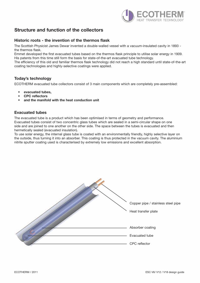
Evacuated tubesThe evacuated tube is a product which has been optimised in terms of geometry and performance.Evacuated tubes consist of two concentric glass tubes which are sealed in a semi-circular shape on one side and are joined to one another on the other side. The space between the tubes is evacuated and then hermetically sealed (evacuated insulation).To use solar energy, the internal glass tube is coated with an environmentally friendly, highly selective layer on the outside, thus turning it into an absorber. This coating is thus protected in the vacuum cavity. The aluminiumnitrite sputter coating used is characterised by extremely low emissions and excellent absorption.
Copper pipe / stainless steel pipe
Heat transfer plate
Absorber coating
Evacuated tube
CPC reflector
ECOTHERM / 2011 ESC V6/ V12 / V18 design guide
Structure and function of the collectors
ECOTHERM evacuated tube collectors consist of 3 main components which are completely pre-assembled:
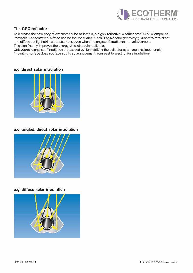
The CPC reflectorTo increase the efficiency of evacuated tube collectors, a highly reflective, weather-proof CPC (CompoundParabolic Concentrator) is fitted behind the evacuated tubes. The reflector geometry guarantees that direct and diffuse sunlight strikes the absorber, even when the angles of irradiation are unfavourable. This significantly improves the energy yield of a solar collector.Unfavourable angles of irradiation are caused by light striking the collector at an angle (azimuth angle) (mounting surface does not face south, solar movement from east to west, diffuse irradiation).
e.g. direct solar irradiation
e.g. angled, direct solar irradiation
e.g. diffuse solar irradiation
ECOTHERM / 2011 ESC V6/ V12 / V18 design guide
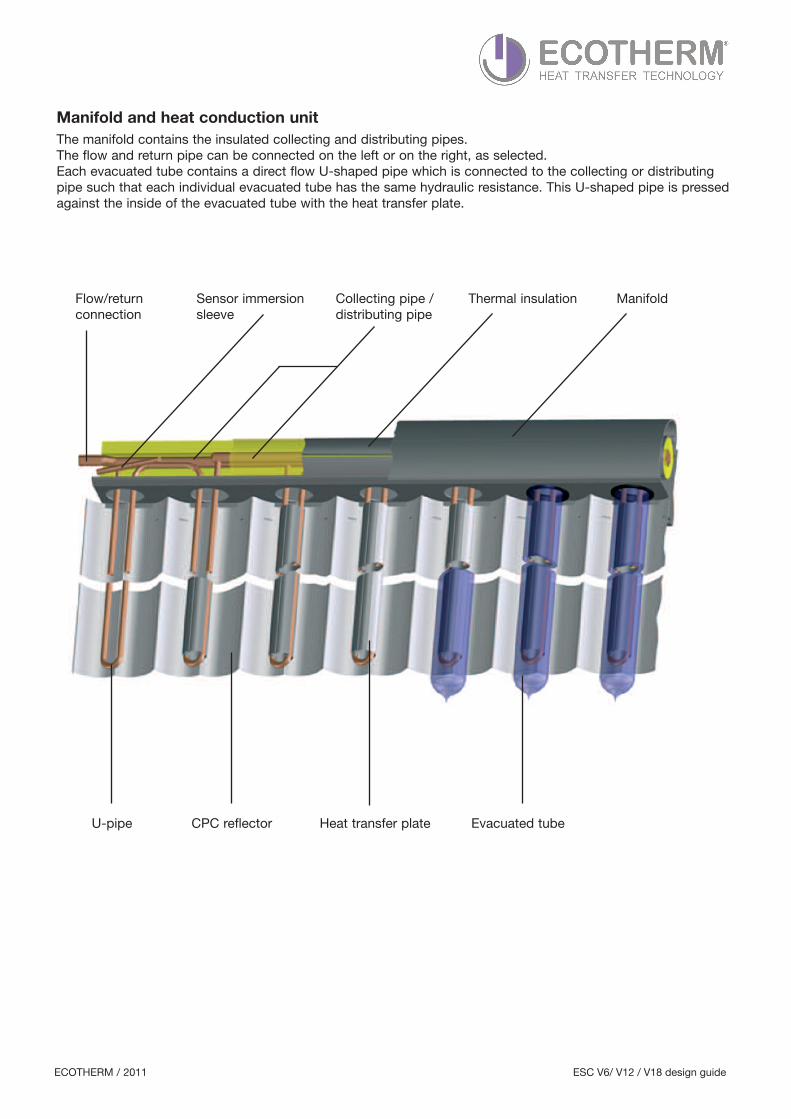
Manifold and heat conduction unitThe manifold contains the insulated collecting and distributing pipes.The flow and return pipe can be connected on the left or on the right, as selected.Each evacuated tube contains a direct flow U-shaped pipe which is connected to the collecting or distributingpipe such that each individual evacuated tube has the same hydraulic resistance. This U-shaped pipe is pressedagainst the inside of the evacuated tube with the heat transfer plate.
U-pipe CPC reflector
ManifoldFlow/return connection
Thermal insulation
Heat transfer plate
Collecting pipe / distributing pipe
Sensor immersionsleeve
Evacuated tube
ECOTHERM / 2011 ESC V6/ V12 / V18 design guide
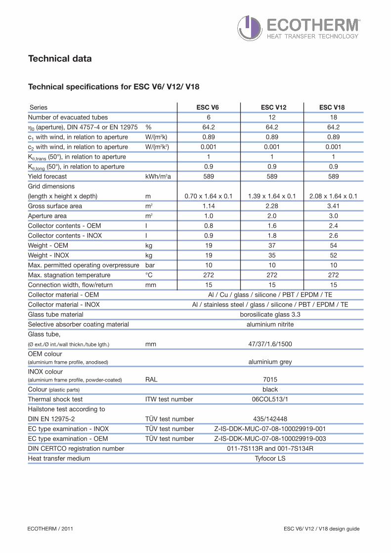
Number of evacuated tubes 6 12 18
η0 (aperture), DIN 4757-4 or EN 12975 % 64.2 64.2 64.2
c1 with wind, in relation to aperture W/(m2k) 0.89 0.89 0.89
c2 with wind, in relation to aperture W/(m2k2) 0.001 0.001 0.001
Kθ,trans (50°), in relation to aperture 1 1 1
Kθ,long (50°), in relation to aperture 0.9 0.9 0.9
Yield forecast kWh/m2a 589 589 589
Grid dimensions
(length x height x depth) m 0.70 x 1.64 x 0.1 1.39 x 1.64 x 0.1 2.08 x 1.64 x 0.1
Gross surface area m2 1.14 2.28 3.41
Aperture area m2 1.0 2.0 3.0
Collector contents - OEM I 0.8 1.6 2.4
Collector contents - INOX I 0.9 1.8 2.6
Weight - OEM kg 19 37 54
Weight - INOX kg 19 35 52
Max. permitted operating overpressure bar 10 10 10
Max. stagnation temperature °C 272 272 272
Connection width, flow/return mm 15 15 15
Collector material - OEM Al / Cu / glass / silicone / PBT / EPDM / TE
Collector material - INOX Al / stainless steel / glass / silicone / PBT / EPDM / TE
Glass tube material borosilicate glass 3.3
Selective absorber coating material aluminium nitrite
Glass tube,
(Ø ext./Ø int./wall thickn./tube lgth.) mm 47/37/1.6/1500
OEM colour(aluminium frame profile, anodised) aluminium grey
INOX colour(aluminium frame profile, powder-coated) RAL 7015
Colour (plastic parts) black
Thermal shock test ITW test number 06COL513/1
Hailstone test according to
DIN EN 12975-2 TÜV test number 435/142448
EC type examination - INOX TÜV test number Z-IS-DDK-MUC-07-08-100029919-001
EC type examination - OEM TÜV test number Z-IS-DDK-MUC-07-08-100029919-003
DIN CERTCO registration number 011-7S113R and 001-7S134R
Heat transfer medium Tyfocor LS
ECOTHERM / 2011 ESC V6/ V12 / V18 design guide
Technical data
Technical specifications for ESC V6/ V12/ V18
Series ESC V6 ESC V12 ESC V18
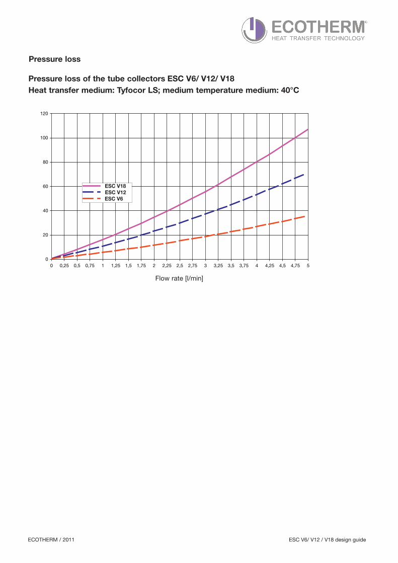
Heat transfer medium: Tyfocor LS; medium temperature medium: 40°C
Flow rate [l/min]
0
20
40
60
80
100
120
0 0,25 0,5 0,75 1 1,25 1,5 1,75 2 2,25 2,5 2,75 3 3,25 3,5 3,75 4 4,25 4,5 4,75 5
Pressure loss
ECOTHERM / 2011 ESC V6/ V12 / V18 design guide
Pressure loss of the tube collectors ESC V6/ V12/ V18
ESC V18 ESC V12 ESC V6
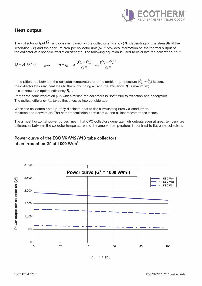
The collector output is calculated based on the collector efficiency ( ) depending on the strength of theirradiation (G*) and the aperture area per collector unit (A). It provides information on the thermal output of the collector at a specific irradiation strength. The following equation is used to calculate the collector output:
with:
If the difference between the collector temperature and the ambient temperature ( ) is zero, the collector has zero heat loss to the surrounding air and the efficiency is maximum; this is known as optical efficiency .
Part of the solar irradiation (G*) which strikes the collectors is “lost” due to reflection and absorption. The optical efficiency takes these losses into consideration.
When the collectors heat up, they dissipate heat to the surrounding area via conduction, radiation and convection. The heat transmission coefficient a1 and a2 incorporate these losses.
The almost horizontal power curves mean that CPC collectors generate high outputs even at great temperaturedifferences between the collector temperature and the ambient temperature, in contrast to flat plate collectors.
at an irradiation G* of 1000 W/m2
Power output per collector unit[W
]
Power curve (G* = 1000 W/m )
0
500
1.000
1.500
2.000
2.500
3.000
0 20 40 60 80 100
][ K)(am
ϑϑ −
Heat output
ECOTHERM / 2011 ESC V6/ V12 / V18 design guide
Power curve of the ESC V6 /V12 /V18 tube collectors
ESC V12
ESC V18
ESC V6
ESC V18
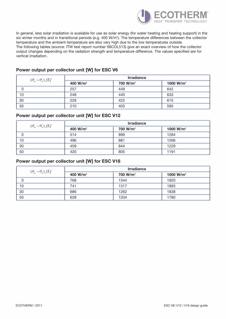
In general, less solar irradiation is available for use as solar energy (for water heating and heating support) in thesix winter months and in transitional periods (e.g. 400 W/m2). The temperature differences between the collectortemperature and the ambient temperature are also very high due to the low temperatures outside. The following tables (source: ITW test report number 06COL513) give an exact overview of how the collector output changes depending on the radiation strength and temperature difference. The values specified are for vertical irradiation.
Irradiance
400 W/m2 700 W/m2 1000 W/m2
0 257 449 642
10 248 440 633
30 229 422 615
50 210 403 595
Irradiance
400 W/m2 700 W/m2 1000 W/m2
0 514 899 1284
10 496 881 1266
30 459 844 1229
50 420 805 1191
Irradiance
400 W/m2 700 W/m2 1000 W/m2
0 768 1344 1920
10 741 1317 1893
30 686 1262 1838
50 628 1204 1780
ECOTHERM / 2011 ESC V6/ V12 / V18 design guide
Power output per collector unit [W] for ESC V6
Power output per collector unit [W] for ESC V12
Power output per collector unit [W] for ESC V18

The solar controllers for tube collector systems should have a “push-start” function. This “push-start” functionprevents excessive temperature differences between the temperature measured at the collector sensor and thetemperature in the lower/middle part of the tubes. The “push-start” (activation) of the pump is to be startedapprox. two to three times per minute for approx. 3-5 seconds when a temperature increase is detected at thecollector sensor to pump the hotter solar fluid to the measuring point.
ECOTHERM / 2011 ESC V6/ V12 / V18 design guide
Notes on solar controllers

An average throughput of 30 - 40 l/h per m2 of aperture area (approx. 0.5 - 0.7 l/min per m2) can be assumedwhen selecting the piping dimensions. We recommend low-flow operation for large-scale solar energy systems,as the specific flow rate can be reduced to 12 - 18 l/h m2 (approx. 0.2 - 0.3 l/min per m2). In order to keep pipingwork to a minimum, we recommend that you connect max. 9.0 m2 (high-flow) and 15 m2 (low-flow) of collectoraperture area in series. In order to minimise the pressure loss due to the solar energy system piping, the flowspeed in the copper piping should not exceed 1 m/s. We recommend flow speeds of between 0.3 and 0.5 m/s.The cross sections should be dimensioned in accordance with throughput and speed as in a standard heatingsystem. We recommend that you use standard copper piping and gunmetal fittings when installing the collectors.The connection points of the pipes should be brazed or connected using olive connections due to the high stagnation temperatures. No galvanised pipes, galvanised fittings or graphite seals may be used. Hemp may only be used in conjunction with pressure and temperature resistant sealant. The components used must beresistant to the heat transfer medium. The thermal insulation of pipes outdoors must be temperature and UV radiation-resistant and resistant to bird damage.
Guidelines for selecting pipe diameter dimensions
High-flow
Aperture area m2 2 3 4 5 6 7 8 9
Flow rate litres/min 1.5 2.5 3 3.5 3.5 4 4 4.5
Copper pipe dimensions 12 x 1 12 x 1 12 x 1 15 x 1 15 x 1 15 x 1 15 x 1 18 x 1
Low-flow
Aperture area m2 5 6 7 8 9 10 11 12
Flow rate litres/min 1.5 1.5 1.5 2 2 2.5 2.5 2.5
Copper pipe dimensions 12 x 1 12 x 1 12 x 1 12 x 1 12 x 1 12 x 1 12 x 1 12 x 1
Aperture area m2 13 14 15
Flow rate litres/min 3 3 3.5
Copper pipe dimensions 12 x 1 12 x 1 15 x 1
ECOTHERM / 2011 ESC V6/ V12 / V18 design guide
Design of the collector connection lines
for series connection of ESC V6 / V12 / V18 collectors and a pump with a head height of max. 6 m.
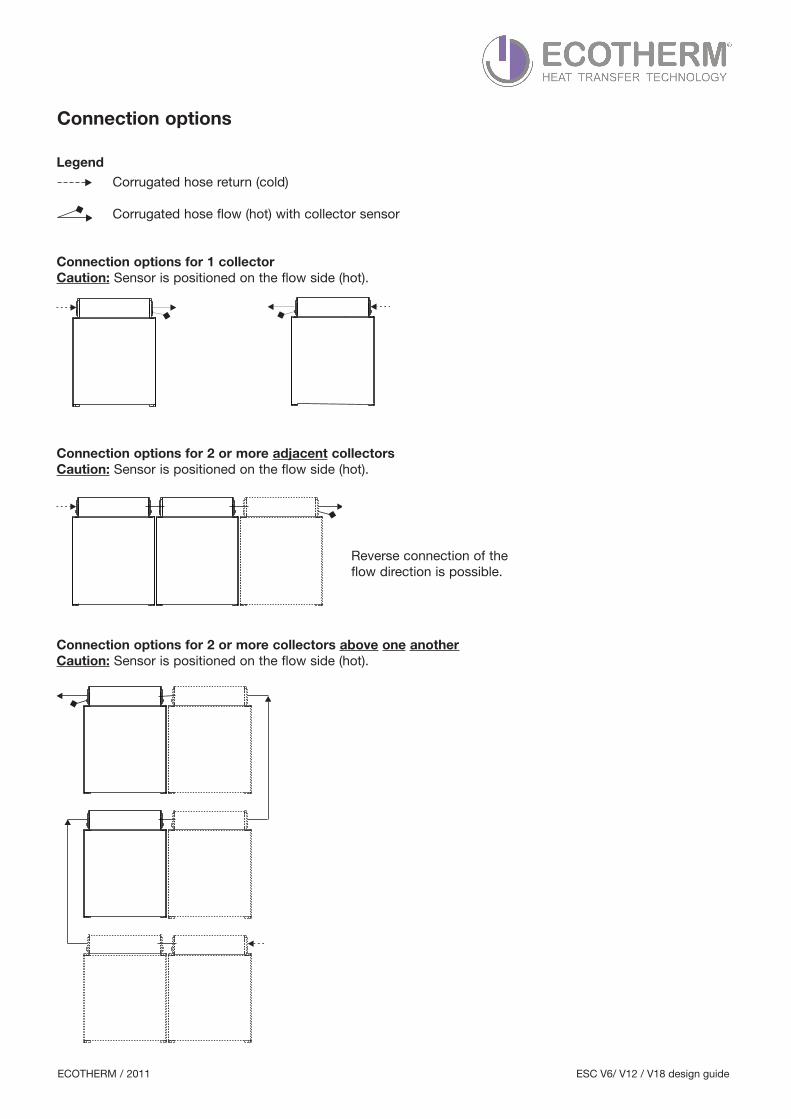
LegendCorrugated hose return (cold)
Corrugated hose flow (hot) with collector sensor
Connection options for 1 collectorCaution: Sensor is positioned on the flow side (hot).
Connection options for 2 or more adjacent collectorsCaution: Sensor is positioned on the flow side (hot).
Connection options for 2 or more collectors above one anotherCaution: Sensor is positioned on the flow side (hot).
Reverse connection of theflow direction is possible.
ECOTHERM / 2011 ESC V6/ V12 / V18 design guide
Connection options
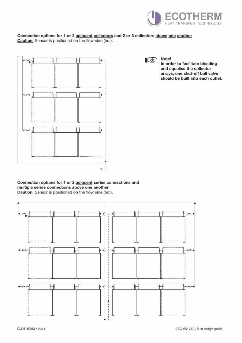
Connection options for 1 or 2 adjacent collectors and 2 or 3 collectors above one anotherCaution: Sensor is positioned on the flow side (hot).
Connection options for 1 or 2 adjacent series connections and multiple series connections above one anotherCaution: Sensor is positioned on the flow side (hot).
Note!In order to facilitate bleedingand equalise the collector arrays, one shut-off ball valve should be built into each outlet.
ECOTHERM / 2011 ESC V6/ V12 / V18 design guide
ECOTHERM / 2011 ESC V6/ V12 / V18 design guide
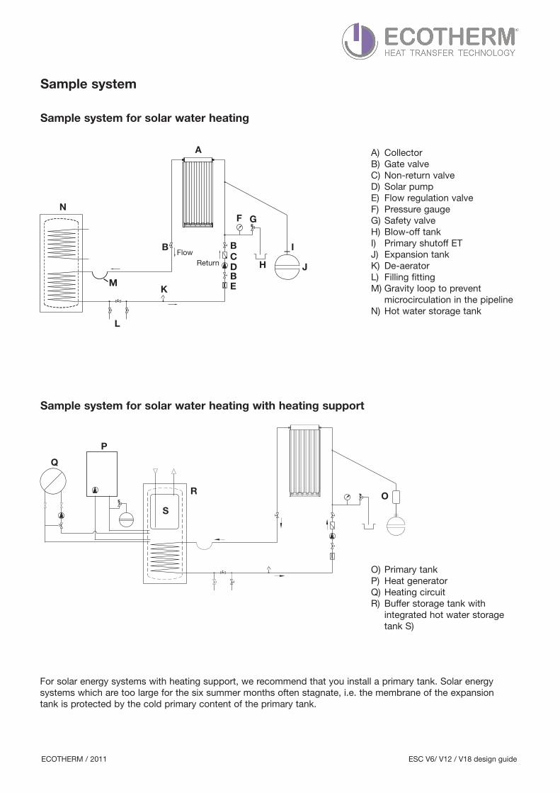
For solar energy systems with heating support, we recommend that you install a primary tank. Solar energy systems which are too large for the six summer months often stagnate, i.e. the membrane of the expansion tank is protected by the cold primary content of the primary tank.
O) Primary tankP) Heat generatorQ) Heating circuitR) Buffer storage tank with integrated hot water storagetank S)
OR
S
P
Q
ReturnFlow
M
N
L
K
H
B B
E
C
BD J
I
GF
A A) CollectorB) Gate valveC) Non-return valveD) Solar pumpE) Flow regulation valveF) Pressure gaugeG) Safety valveH) Blow-off tankI) Primary shutoff ETJ) Expansion tankK) De-aeratorL) Filling fitting
microcirculation in the pipelineN) Hot water storage tank
ECOTHERM / 2011 ESC V6/ V12 / V18 design guide
Sample system
Sample system for solar water heating
Sample system for solar water heating with heating support
M) Gravity loop to prevent
ECOTHERM / 2011 ESC V6/ V12 / V18 design guide
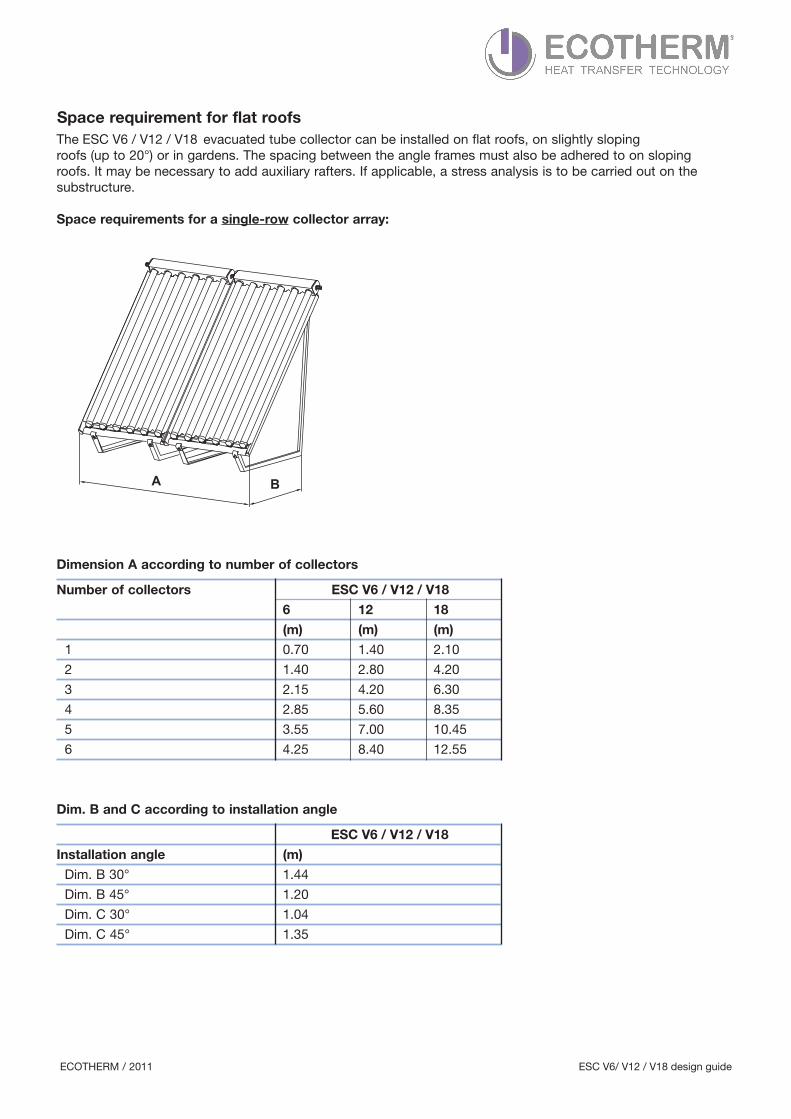
roofs (up to 20°) or in gardens. The spacing between the angle frames must also be adhered to on sloping roofs. It may be necessary to add auxiliary rafters. If applicable, a stress analysis is to be carried out on the substructure.
Space requirements for a single-row collector array:
Dimension A according to number of collectors
Dim. B and C according to installation angle
BA
ECOTHERM / 2011 ESC V6/ V12 / V18 design guide
Space requirement for flat roofs
Number of collectors ESC V6 / V12 / V18
ESC V6 / V12 / V18
The ESC V6 / V12 / V18 evacuated tube collector can be installed on flat roofs, on slightly sloping
6 12 18
(m) (m) (m)
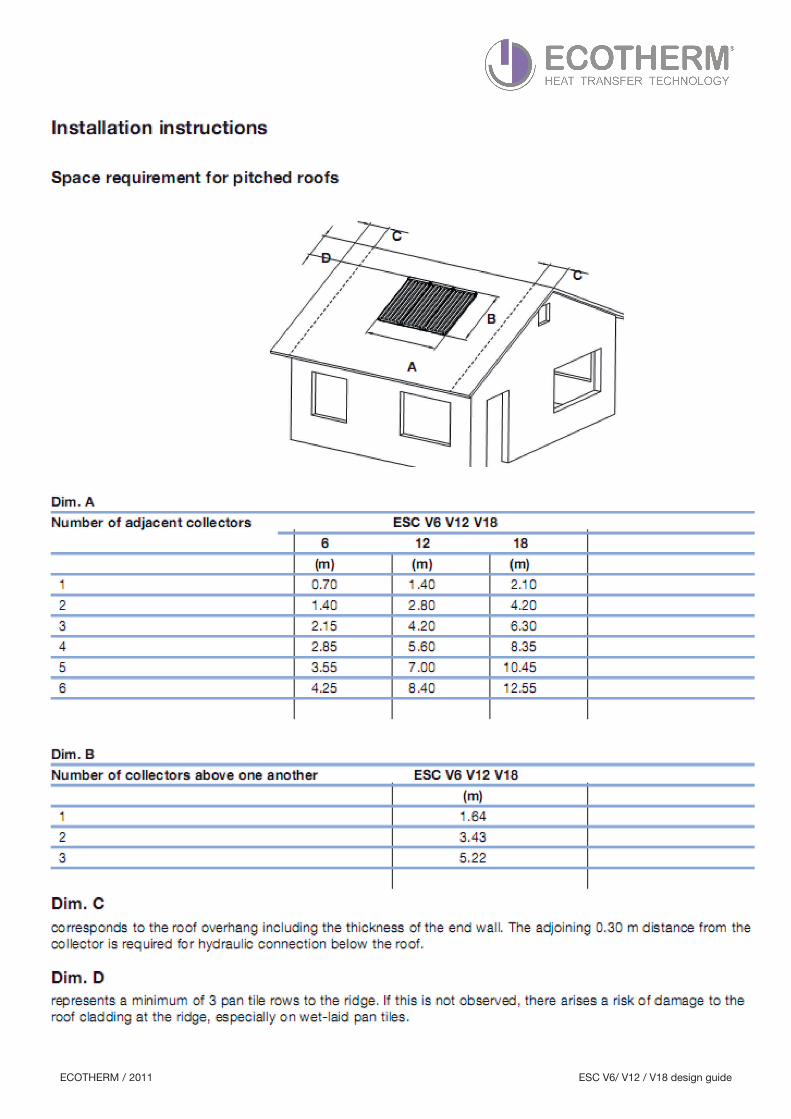
1 0.70 1.40 2.10
2 1.40 2.80 4.20
3 2.15 4.20 6.30
4 2.85 5.60 8.35
5 3.55 7.00 10.45
6 4.25 8.40 12.55
Installation angle (m)
Dim. B 30° 1.44
Dim. B 45° 1.20
Dim. C 30° 1.04
Dim. C 45° 1.35
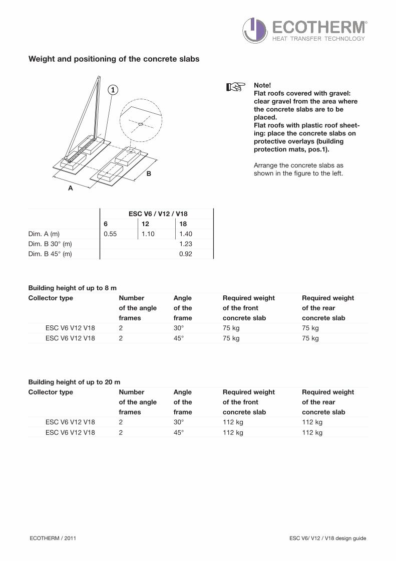
Dim. B 30° (m) 1.23
Dim. B 45° (m) 0.92
Building height of up to 8 m
Collector type Number Angle Required weight Required weight
of the angle of the of the front of the rear
frames frame concrete slab concrete slab
Building height of up to 20 m
Collector type Number Angle Required weight Required weight
of the angle of the of the front of the rear
frames frame concrete slab concrete slab
Note!Flat roofs covered with gravel :clear gravel from the area wherethe concrete slabs are to beplaced. Flat roofs with plastic roof sheet-ing: place the concrete slabs onprotective overlays (building protection mats, pos.1).
Arrange the concrete slabs as shown in the figure to the left.
A
B
ECOTHERM / 2011 ESC V6/ V12 / V18 design guide
Weight and positioning of the concrete slabs
ESC V6 / V12 / V18
6 12 18
Dim. A (m) 0.55 1.10 1.40
ESC V6 V12 V18 2 45° 75 kg 75 kg
ESC V6 V12 V18 2 30° 75 kg 75 kg
ESC V6 V12 V18 2 30° 112 kg 112 kg
ESC V6 V12 V18 2 45° 112 kg 112 kg
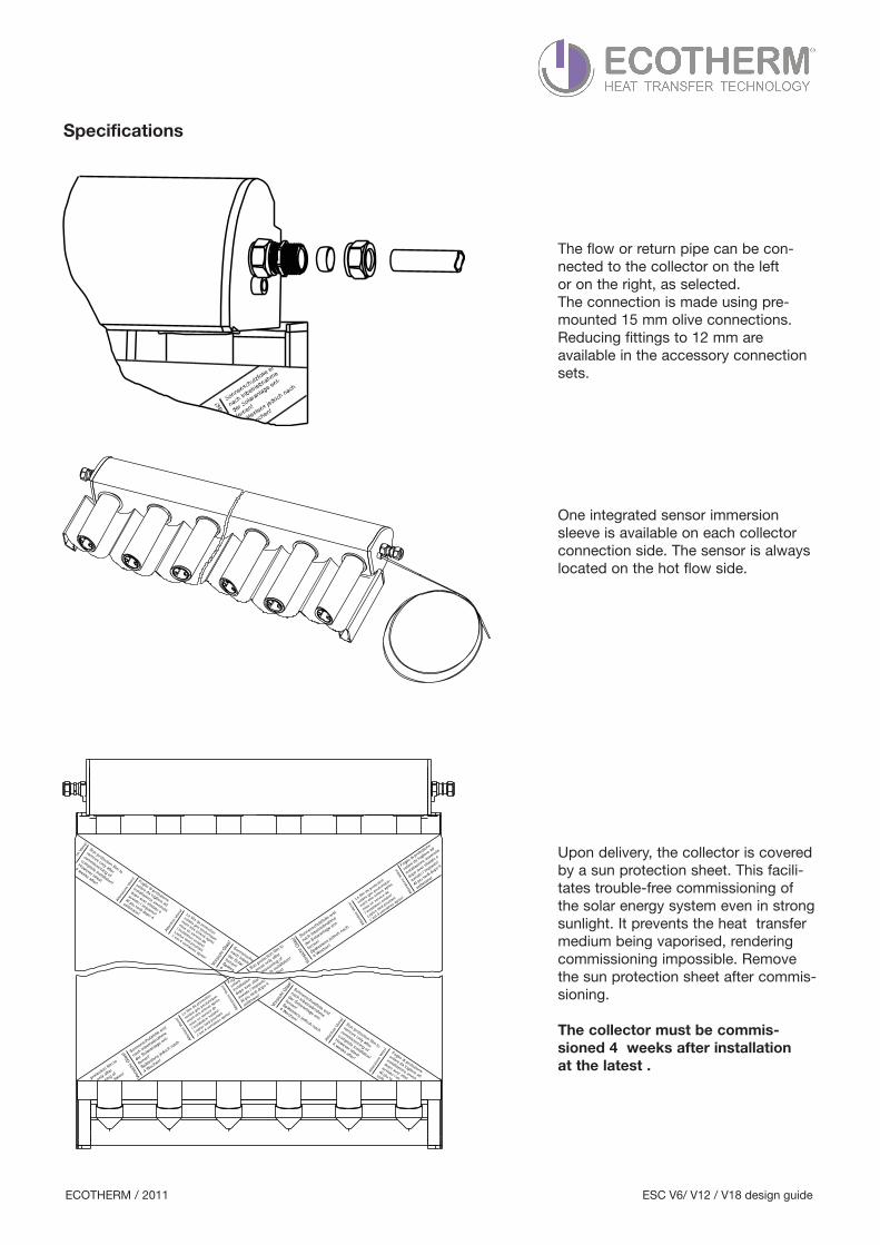
The flow or return pipe can be con-nected to the collector on the left or on the right, as selected.The connection is made using pre-mounted 15 mm olive connections. Reducing fittings to 12 mm are available in the accessory connectionsets.
One integrated sensor immersionsleeve is available on each collectorconnection side. The sensor is alwayslocated on the hot flow side.
Upon delivery, the collector is coveredby a sun protection sheet. This facili-tates trouble-free commissioning ofthe solar energy system even in strongsunlight. It prevents the heat transfermedium being vaporised, renderingcommissioning impossible. Removethe sun protection sheet after commis-sioning.
The collector must be commis-sioned 4 weeks after installation at the latest .
ECOTHERM / 2011 ESC V6/ V12 / V18 design guide
Specifications