Embed Size (px)
Citation preview

PRODUCT SPECIFICATION & USER GUIDE
Document Number: DOC00450
Document Revision: M
Product Part Number: MP00062
Product Revision: G
MEMSENSE.COM
888.668.8743
Information provided herein is considered accurate however is not guaranteed. Memsense reserves the right to change specifications at any time, without notice.
Document Number: DOC00450 Document Revision: M pg. i
TABLE OF CONTENTS
1.0 OVERVIEW ....................................................................................................................................... 1
2.0 INERTIAL SPECIFICATIONS ............................................................................................................... 1
3.0 MECHANICAL ................................................................................................................................... 3
3.1 Dimensions ...................................................................................................................................... 3
3.2 Coordinate System .......................................................................................................................... 4
4.0 COMMUNICATIONS ......................................................................................................................... 5
4.1 Default Settings ............................................................................................................................... 5
4.2 Hardware Interface ......................................................................................................................... 5
4.2.1 Time of Validity Output – Internal Sample Rate ....................................................................... 6
4.2.2 External Trigger Input .............................................................................................................. 6
4.2.3 1 Pulse Per Second Input ......................................................................................................... 7
4.3 Internal Sample Rate ....................................................................................................................... 7
4.4 Communication Interface Protocol .................................................................................................. 7
4.4.1 IMU Sample Rate Configure 0X0204 ........................................................................................ 9
4.4.2 Configure Filter 0X0203 ........................................................................................................... 9
4.4.3 Select Sensors 0X0205........................................................................................................... 10
4.4.4 Config Gyro Range 0X0208 .................................................................................................... 11
5.0 OPTIONS ........................................................................................................................................ 12
5.1 Part Numbering ............................................................................................................................. 12
5.2 MS-IMU3020 Accessories .............................................................................................................. 12
5.3 MS-IMU3020 Development Kit Part Numbering ........................................................................... 12
6.0 DOCUMENT REVISION HISTORY .................................................................................................... 13
7.0 PRODUCT REVISION HISTORY ........................................................................................................ 14

Information provided herein is considered accurate however is not guaranteed. Memsense reserves the right to change specifications at any time, without notice. Document Number DOC00450 Document Revision: M Page 1
1.0 OVERVIEW
The MS-IMU3020 inertial measurement unit delivers
market leading price to performance in an ultra-compact
aluminum package. The gyro bias instability of 1 /h and
accelerometer bias instability of 14.8 µg supply ample
inertial performance to support a range of applications
from UAS navigation and control to pipeline inspection.
User configurable options allow the IMU to be tuned to
your application with configurable bandwidth, sample rate,
gyro ranges, 1 PPS input and other measurement
parameters. Streamline your global operation and improve
performance with the MS-IMU3020 that requires no export
license. The IMU provides all these features in a package
that only measures 1.1 x 1.1 x 0.4 inches with a mass of
only 20 grams. The MS-IMU3020’s combination of inertial
performance, size, configurability, and value surpasses all
IMUs in the market.
2.0 INERTIAL SPECIFICATIONS
Table 1 - Specifications
ACCELERATION TYPICAL MAX UNITS NOTES
Dynamic Range ± 15 g Note 1
Bias Instability 14.8 µg Typical
Offset ±1.2 ±7.0 mg
Nonlinearity ±0.3 % of FS Typical
Velocity Random Walk 0.078 m/s/h -1/2 Typical
Noise Density 160 µg/Hz-1/2 Typical
Vibration Rectification Coef. 482.5 µg/grms2 Typical, Note 2
Bandwidth 50 Hz -3dB point, Note 3
ANGULAR RATE UNITS NOTES
Dynamic Range ±120 ±240 ±480 ±960 ±1920 /s Minimum, Note 4
Bias Instability 1.06 1.06 1.06 1.06 1.31 /h Typical
Offset 20.5
100.0 19.0
100.0 16.6
100.0 19.3
120.0 25.3
200.0 /h
Typical Max
Nonlinearity % of FS Typical, Note 5
Angle Random Walk 0.22 0.22 0.22 0.22 0.22 /h -1/2 Typical
Noise Density /s /Hz-1/2 Typical
Vibration Rectification Coef. /h/grms2 Typical, Note 2
Bandwidth 50
230 50
230 50
230 50
230 50
230 Hz
Typical Max -3dB point, Note 3
1. The MS-IMU3020 will not output greater than ± 15 g.
2. Parameter derived with 6 g rms random vibration input 30Hz to 2000Hz.
3. Bandwidth is configurable see section 4.4.2 Configure Filter.
4. Angular rate dynamic range is configurable see section 4.4.5 Config Gyro Range.
5. Nonlinearity is specified from -30 to 85C at angular rate of ± 450 /s.
Information provided herein is considered accurate however is not guaranteed. Memsense reserves the right to change specifications at any time, without notice.
Document Number: DOC00450 Document Revision: M pg. 2
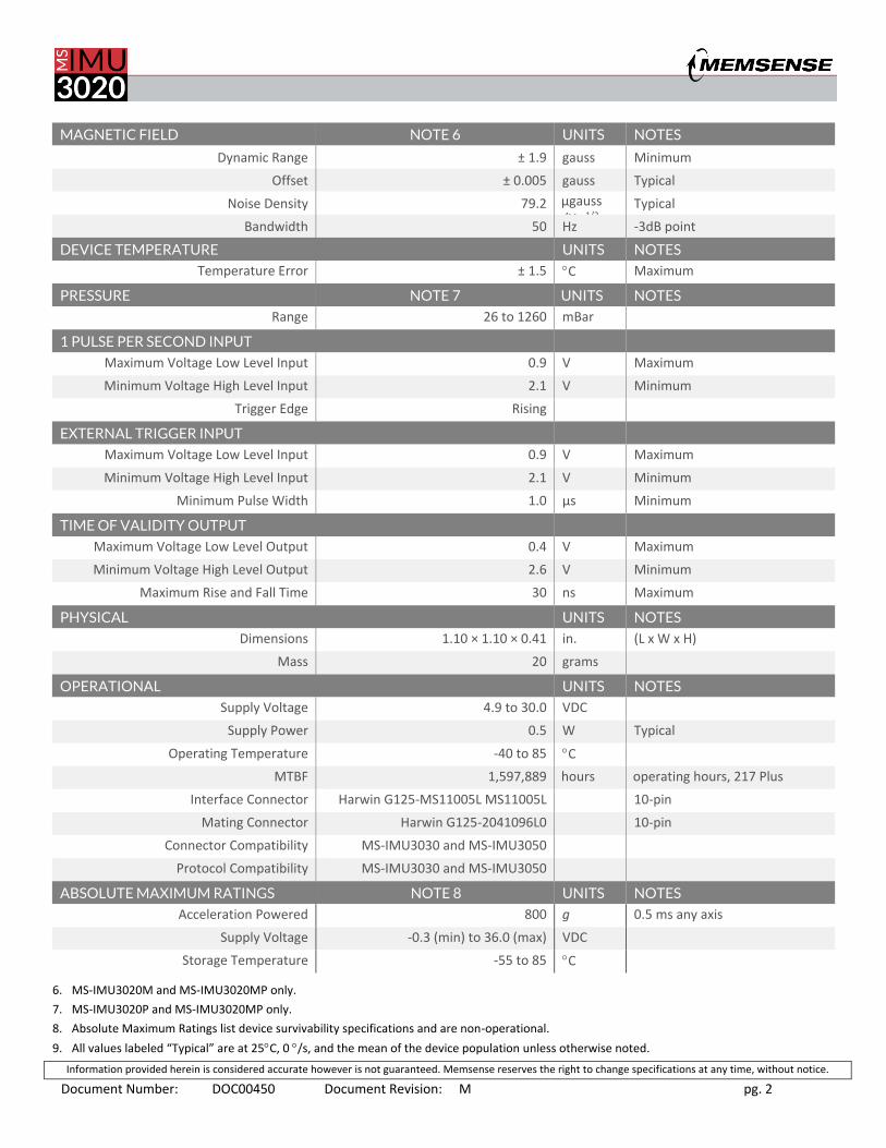
MAGNETIC FIELD NOTE 6 UNITS NOTES
Dynamic Range ± 1.9 gauss Minimum
Offset ± 0.005 gauss Typical
Noise Density 79.2 µgauss /Hz-1/2
Typical
Bandwidth 50 Hz -3dB point
DEVICE TEMPERATURE UNITS NOTES
Temperature Error ± 1.5 C Maximum
PRESSURE NOTE 7 UNITS NOTES
Range 26 to 1260 mBar
1 PULSE PER SECOND INPUT
Maximum Voltage Low Level Input 0.9 V Maximum
Minimum Voltage High Level Input 2.1 V Minimum
Trigger Edge Rising
EXTERNAL TRIGGER INPUT
Maximum Voltage Low Level Input 0.9 V Maximum
Minimum Voltage High Level Input 2.1 V Minimum
Minimum Pulse Width 1.0 µs Minimum
TIME OF VALIDITY OUTPUT
Maximum Voltage Low Level Output 0.4 V Maximum
Minimum Voltage High Level Output 2.6 V Minimum
Maximum Rise and Fall Time 30 ns Maximum
PHYSICAL UNITS NOTES
Dimensions 1.10 × 1.10 × 0.41 in. (L x W x H)
Mass 20 grams
OPERATIONAL UNITS NOTES
Supply Voltage 4.9 to 30.0 VDC
Supply Power 0.5 W Typical
Operating Temperature -40 to 85 C
MTBF 1,597,889 hours operating hours, 217 Plus
Interface Connector Harwin G125-MS11005L MS11005L 10-pin
Mating Connector Harwin G125-2041096L0 10-pin
Connector Compatibility MS-IMU3030 and MS-IMU3050
Protocol Compatibility MS-IMU3030 and MS-IMU3050
ABSOLUTE MAXIMUM RATINGS NOTE 8 UNITS NOTES
Acceleration Powered 800 g 0.5 ms any axis
Supply Voltage -0.3 (min) to 36.0 (max) VDC
Storage Temperature -55 to 85 C
6. MS-IMU3020M and MS-IMU3020MP only.
7. MS-IMU3020P and MS-IMU3020MP only.
8. Absolute Maximum Ratings list device survivability specifications and are non-operational.
9. All values labeled “Typical” are at 25C, 0 /s, and the mean of the device population unless otherwise noted.

Information provided herein is considered accurate however is not guaranteed. Memsense reserves the right to change specifications at any time, without notice.
Document Number: DOC00450 Document Revision: M pg. 3
MS-IMU3020 ALLAN VARIANCE CURVES
3.0 MECHANICAL
3.1 Dimensions
The MS-IMU3020 is contained in a 6061-T6 aluminum housing anodized to MIL-A-8625 standards. Mounting of the IMU is
achieved through four 2-56 captive socket head cap screws while alignment is facilitated through two one sixteenth inch
dowel pins. The mounting surface of the IMU’s mechanical interface is flat to within one one-thousandths of an inch. The
dimensions below are only an overview of the housing, detailed mechanical drawings in Imperial and Metric units are
provided at Memsense.com under the MS-IMU3020 product page.
Figure 1 - Physical dimensions (inches)

Information provided herein is considered accurate however is not guaranteed. Memsense reserves the right to change specifications at any time, without notice.
Document Number: DOC00450 Document Revision: M pg. 4
3.2 Coordinate System
The coordinate system for the MS-IMU3020 follows the right-hand rule convention. As an example, with the inertial
measurement unit pictured in Figure 2, if the Z axis is pointed straight UP away from the earth, it will produce 0 g for the X
and Y axes and a positive 1 g for the Z axis. A counterclockwise rotation of the IMU about any of the depicted axis will
produce a positive angular rate output for the corresponding axis. The magnetometer sign convention produces a positive
output on the corresponding axis aligned in the North direction with the IMU bottom parallel and facing the Earth’s surface.
Figure 2 – MS-IMU3020 coordinate system
Information provided herein is considered accurate however is not guaranteed. Memsense reserves the right to change specifications at any time, without notice.
Document Number: DOC00450 Document Revision: M pg. 5
4.0 COMMUNICATIONS
4.1 Default Settings
The MS-IMU3020 is configured in manufacture to default settings. Knowledge of these settings is important when
connecting to the IMU in the MS-CIP Evaluation Application. The following table provides the necessary default settings to
connect to the IMU.
Table 2 –IMU Default Settings
SETTING DEFAULT
Baud Rate 460800 bps
Start Bit 1
Stop Bit 1
Data Bits 8
Parity None
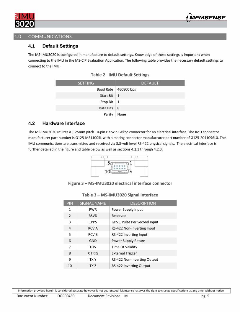
4.2 Hardware Interface
The MS-IMU3020 utilizes a 1.25mm pitch 10-pin Harwin Gekco connector for an electrical interface. The IMU connector
manufacturer part number is G125-MS11005L with a mating connector manufacturer part number of G125-2041096L0. The
IMU communications are transmitted and received via 3.3-volt level RS-422 physical signals. The electrical interface is
further detailed in the figure and table below as well as sections 4.2.1 through 4.2.3.
Figure 3 – MS-IMU3020 electrical interface connector
Table 3 – MS-IMU3020 Signal Interface
PIN SIGNAL NAME DESCRIPTION
1 PWR Power Supply Input
2 RSVD Reserved
3 1PPS GPS 1 Pulse Per Second Input
4 RCV A RS-422 Non-Inverting Input
5 RCV B RS-422 Inverting Input
6 GND Power Supply Return
7 TOV Time Of Validity
8 X TRIG External Trigger
9 TX Y RS-422 Non-Inverting Output
10 TX Z RS-422 Inverting Output

Information provided herein is considered accurate however is not guaranteed. Memsense reserves the right to change specifications at any time, without notice.
Document Number: DOC00450 Document Revision: M pg. 6
4.2.1 Time of Validity Output – Internal Sample Rate
The Time of Validity (TOV), pin 7, output provides a signal that indicates when the internal sensors are sampled at the
internal sample rate and when the samples complete transmission. The TOV falling edge is correlated with sampling of the
first element in a sample. The TOV rising edge occurs after the last bit of a sample has finished transmission. Figure 4
provides a timing diagram depicting the relation between the internal sample rate, sample transmission and the TOV
output. See 4.1.2 External Trigger Input for TOV output with external trigger enabled.
Figure 4 – TOV timing diagram with output sample rate at decimation of 2.
4.2.2 External Trigger Input
The External Trigger (X TRIG), pin 8, input provides a means to synchronize the IMU’s sample transmission with an external
sampling period. A falling edge signal on the External Trigger input initiates the transmission of the most recent complete
sample. When in the External Trigger Mode, the TOV falling edge occurs with the beginning of an internal sample and its
rising edge is initiated by the completion of the sample’s compensation. Figure 5 depicts the timing associated with the use
of the External Trigger and its relation to the TOV signal.
Please note that the External Trigger Mode must be enabled through the communications protocol for the input to be
active, see the protocol section or the MS-CIP specification for details on enabling or disabling the External Trigger.

Information provided herein is considered accurate however is not guaranteed. Memsense reserves the right to change specifications at any time, without notice.
Document Number: DOC00450 Document Revision: M pg. 7
Figure 5 – External Trigger timing diagram.
4.2.3 1 Pulse Per Second Input
The 1 Pulse Per Second Input (1 PPS), pin 3, provides a means to synchronize the IMU’s sample transmission with a GPS receiver’s 1 pulse per second output. A Rising Edge signal on the 1 PPS input time initiates a time reset to the nearest second.
4.3 Internal Sample Rate
The MS-IMU3020 internally samples sensors selected by the configuration at a rate of 800 samples per second. The internal
sample rate is used in the output sample rate configuration detailed in the Memsense Communication Interface Protocol.
4.4 Communication Interface Protocol
The communication interface protocol is defined in detail in the Memsense Communication Interface Protocol document
(MS-CIP DOC00381) which can be found on the MS-IMU3020 product page at memsense.com. The following information
provides an overview and contains MS-IMU3020 specific portions of the communication protocol.
The Memsense Communication Interface Protocol (MS CIP) is implemented as a simple architecture to communicate
information to and from the measurement device. The protocol is intended to be flexible in allowing customers to configure
various features of the device achieving optimized communication modes for various application requirements. Below is a
table showing the default output from the MS-IMU3020.

Information provided herein is considered accurate however is not guaranteed. Memsense reserves the right to change specifications at any time, without notice.
Document Number: DOC00450 Document Revision: M pg. 8
Table 4 – Default IMU Data Message 0xA2
BYTE BYTE NAME VALUE DESCRIPTION
0 Sync1 0xA5 First synchronization value used in sample parsing.
1 Sync2 0xA5 Second synchronization value used in sample parsing.
2 Message Type 0xA2 Message type identification code.
3 Payload Size 0x1C Byte length of the payload.
4 Message Code 0x81 Scaled Acceleration Vector identification code.
5 Data Size 0x0C Data Size in bytes.
6 X Accel MSB 0x37 X Accel in g. MSB of F32.
7 X Accel Byte 2 0xA7 X Accel in g. Byte 2 of F32.
8 X Accel Byte 1 0xC5 X Accel in g. Byte 1 of F32.
9 X Accel LSB 0xAC X Accel in g. LSB of F32.
10 Y Accel MSB 0x37 Y Accel in g. MSB of F32.
11 Y Accel Byte 2 0x7B Y Accel in g. Byte 2 of F32.
12 Y Accel Byte 1 0xA8 Y Accel in g. Byte 1 of F32.
13 Y Accel LSB 0x82 Y Accel in g. LSB of F32.
14 Z Accel MSB 0x3F Z Accel in g. MSB of F32.
15 Z Accel Byte 2 0x80 Z Accel in g. Byte 2 of F32.
16 Z Accel Byte 1 0x00 Z Accel in g. Byte 1 of F32.
17 Z Accel LSB 0x65 Z Accel in g. LSB of F32.
18 Message Code 0x82 Scaled Angular Rate Vector identification code.
19 Data Size 0x0C Data Size in bytes.
20 X Gyro MSB 0x37 X Gyro in degrees per second. MSB of F32.
21 X Gyro Byte 2 0xA7 X Gyro in degrees per second. Byte 2 of F32.
22 X Gyro Byte 1 0xC5 X Gyro in degrees per second. Byte 1 of F32.
23 X Gyro LSB 0xAC X Gyro in degrees per second. LSB of F32.
24 Y Gyro MSB 0x37 Y Gyro in degrees per second. MSB of F32.
25 Y Gyro Byte 2 0x7B Y Gyro in degrees per second. Byte 2 of F32.
26 Y Gyro Byte 1 0xA8 Y Gyro in degrees per second. Byte 1 of F32.
27 Y Gyro LSB 0x82 Y Gyro in degrees per second. LSB of F32.
28 Z Gyro MSB 0x37 Z Gyro in degrees per second. MSB of F32.
29 Z Gyro Byte 2 0x49 Z Gyro in degrees per second. Byte 2 of F32.
30 Z Gyro Byte 1 0x53 Z Gyro in degrees per second. Byte 1 of F32.
31 Z Gyro LSB 0x9C Z Gyro in degrees per second. LSB of F32.
32 Checksum 1 0x0C Fletcher-16 checksum block 1 MSB
33 Checksum 2 0x23 Fletcher-16 checksum block 2 LSB
Resulting Complete Command
A5A5A21C810C37A7C5AC377BA8823F800065820C37A7C5AC377BA8823749539C0C23
Information provided herein is considered accurate however is not guaranteed. Memsense reserves the right to change specifications at any time, without notice.
Document Number: DOC00450 Document Revision: M pg. 9
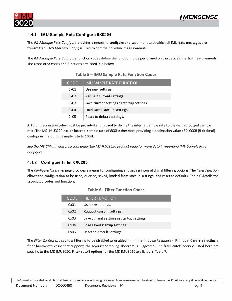
4.4.1 IMU Sample Rate Configure 0X0204
The IMU Sample Rate Configure provides a means to configure and save the rate at which all IMU data messages are
transmitted. IMU Message Config is used to control individual measurements.
The IMU Sample Rate Configure function codes define the function to be performed on the device’s inertial measurements.
The associated codes and functions are listed in 5 below.
Table 5 – IMU Sample Rate Function Codes
CODE IMU SAMPLE RATE FUNCTION
0x01 Use new settings.
0x02 Request current settings.
0x03 Save current settings as startup settings.
0x04 Load saved startup settings.
0x05 Reset to default settings.
A 16-bit decimation value must be provided and is used to divide the internal sample rate to the desired output sample
rate. The MS-IMU3020 has an internal sample rate of 800Hz therefore providing a decimation value of 0x0008 (8 decimal)
configures the output sample rate to 100Hz.
See the MS-CIP at memsense.com under the MS-IMU3020 product page for more details regarding IMU Sample Rate
Configure.
4.4.2 Configure Filter 0X0203
The Configure Filter message provides a means for configuring and saving internal digital filtering options. The Filter Function
allows the configuration to be used, queried, saved, loaded from startup settings, and reset to defaults. Table 6 details the
associated codes and functions.
Table 6 –Filter Function Codes
CODE FILTER FUNCTION
0x01 Use new settings.
0x02 Request current settings.
0x03 Save current settings as startup settings.
0x04 Load saved startup settings.
0x05 Reset to default settings.
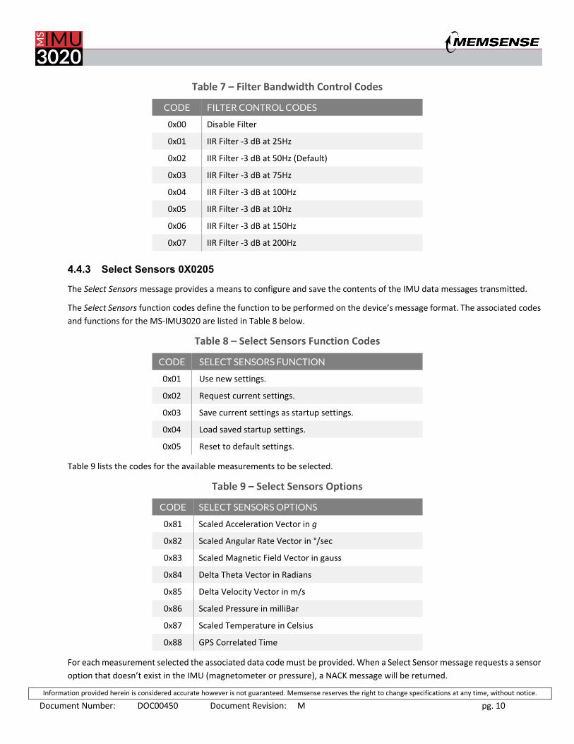
The Filter Control codes allow filtering to be disabled or enabled in Infinite Impulse Response (IIR) mode. Care in selecting a
filter bandwidth value that supports the Nyquist Sampling Theorem is suggested. The filter cutoff options listed here are
specific to the MS-IMU3020. Filter cutoff options for the MS-IMU3020 are listed in Table 7.
Information provided herein is considered accurate however is not guaranteed. Memsense reserves the right to change specifications at any time, without notice.
Document Number: DOC00450 Document Revision: M pg. 10
Table 7 – Filter Bandwidth Control Codes
CODE FILTER CONTROL CODES
0x00 Disable Filter
0x01 IIR Filter -3 dB at 25Hz
0x02 IIR Filter -3 dB at 50Hz (Default)
0x03 IIR Filter -3 dB at 75Hz
0x04 IIR Filter -3 dB at 100Hz
0x05 IIR Filter -3 dB at 10Hz
0x06 IIR Filter -3 dB at 150Hz
0x07 IIR Filter -3 dB at 200Hz
4.4.3 Select Sensors 0X0205
The Select Sensors message provides a means to configure and save the contents of the IMU data messages transmitted.
The Select Sensors function codes define the function to be performed on the device’s message format. The associated codes
and functions for the MS-IMU3020 are listed in Table 8 below.
Table 8 – Select Sensors Function Codes
CODE SELECT SENSORS FUNCTION
0x01 Use new settings.
0x02 Request current settings.
0x03 Save current settings as startup settings.
0x04 Load saved startup settings.
0x05 Reset to default settings.
Table 9 lists the codes for the available measurements to be selected.
Table 9 – Select Sensors Options
CODE SELECT SENSORS OPTIONS
0x81 Scaled Acceleration Vector in g
0x82 Scaled Angular Rate Vector in °/sec
0x83 Scaled Magnetic Field Vector in gauss
0x84 Delta Theta Vector in Radians
0x85 Delta Velocity Vector in m/s
0x86 Scaled Pressure in milliBar
0x87 Scaled Temperature in Celsius
0x88 GPS Correlated Time
For each measurement selected the associated data code must be provided. When a Select Sensor message requests a sensor
option that doesn’t exist in the IMU (magnetometer or pressure), a NACK message will be returned.

Information provided herein is considered accurate however is not guaranteed. Memsense reserves the right to change specifications at any time, without notice.
Document Number: DOC00450 Document Revision: M pg. 11
See the MS-CIP at memsense.com under the MS-IMU3020 product page for more details regarding Select Sensors.
4.4.4 Config Gyro Range 0X0208
The MS-IMU3020 supports the configuration of gyroscope dynamic ranges. The following configuration information details
the options available and associated codes used in the communication protocol.
The Config Gyro Range message provides a means for configuring and saving the triaxial gyroscope dynamic range options.
The Config Gyro Range Function allows the configuration to be used, queried, saved, loaded from startup settings, and reset
to defaults. Table 10 details the associated codes and functions.
Table 10 – Config Gyro Range Function Codes
CODE CONFIG GYRO RANGE FUNCTION CODES
0x01 Use new settings.
0x02 Request current settings.
0x03 Save current settings as startup settings.
0x04 Load saved startup settings.
0x05 Reset to default settings.
The Gyro Range codes allow the dynamic range of the gyroscope to be changed to 1 of the 5 supported ranges and effect all
3 axes of the sensor. The options for the gyroscope dynamic range are controlled in the Gyro Range Codes. The MS-IMU3020
codes are listed in Table 11.
Table 11 – MS-IMU3020 Gyro Range Codes
CODE GYRO RANGE CODES
0x01 Gyroscope range: ±120 /s
0x02 Gyroscope range: ±240 /s
0x03 Gyroscope range: ±480 /s (Default)
0x04 Gyroscope range: ±960 /s
0x05 Gyroscope range: ±1920 /s
Information provided herein is considered accurate however is not guaranteed. Memsense reserves the right to change specifications at any time, without notice.
Document Number: DOC00450 Document Revision: M pg. 12
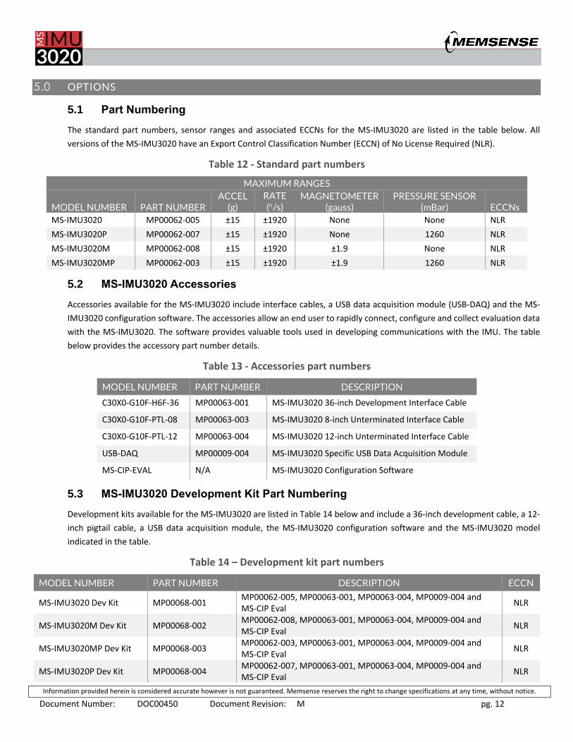
5.0 OPTIONS
5.1 Part Numbering
The standard part numbers, sensor ranges and associated ECCNs for the MS-IMU3020 are listed in the table below. All
versions of the MS-IMU3020 have an Export Control Classification Number (ECCN) of No License Required (NLR).
Table 12 - Standard part numbers
MAXIMUM RANGES
MODEL NUMBER PART NUMBER ACCEL
(g) RATE (/s)
MAGNETOMETER (gauss)
PRESSURE SENSOR (mBar)
ECCNs
MS-IMU3020 MP00062-005 ±15 ±1920 None None NLR
MS-IMU3020P MP00062-007 ±15 ±1920 None 1260 NLR
MS-IMU3020M MP00062-008 ±15 ±1920 ±1.9 None NLR
MS-IMU3020MP MP00062-003 ±15 ±1920 ±1.9 1260 NLR
5.2 MS-IMU3020 Accessories
Accessories available for the MS-IMU3020 include interface cables, a USB data acquisition module (USB-DAQ) and the MS-
IMU3020 configuration software. The accessories allow an end user to rapidly connect, configure and collect evaluation data
with the MS-IMU3020. The software provides valuable tools used in developing communications with the IMU. The table
below provides the accessory part number details.
Table 13 - Accessories part numbers
MODEL NUMBER PART NUMBER DESCRIPTION
C30X0-G10F-H6F-36 MP00063-001 MS-IMU3020 36-inch Development Interface Cable
C30X0-G10F-PTL-08 MP00063-003 MS-IMU3020 8-inch Unterminated Interface Cable
C30X0-G10F-PTL-12 MP00063-004 MS-IMU3020 12-inch Unterminated Interface Cable
USB-DAQ MP00009-004 MS-IMU3020 Specific USB Data Acquisition Module
MS-CIP-EVAL N/A MS-IMU3020 Configuration Software
5.3 MS-IMU3020 Development Kit Part Numbering
Development kits available for the MS-IMU3020 are listed in Table 14 below and include a 36-inch development cable, a 12-
inch pigtail cable, a USB data acquisition module, the MS-IMU3020 configuration software and the MS-IMU3020 model
indicated in the table.
Table 14 – Development kit part numbers
MODEL NUMBER PART NUMBER DESCRIPTION ECCN
MS-IMU3020 Dev Kit MP00068-001 MP00062-005, MP00063-001, MP00063-004, MP0009-004 and MS-CIP Eval
NLR
MS-IMU3020M Dev Kit MP00068-002 MP00062-008, MP00063-001, MP00063-004, MP0009-004 and MS-CIP Eval
NLR
MS-IMU3020MP Dev Kit MP00068-003 MP00062-003, MP00063-001, MP00063-004, MP0009-004 and MS-CIP Eval
NLR
MS-IMU3020P Dev Kit MP00068-004 MP00062-007, MP00063-001, MP00063-004, MP0009-004 and MS-CIP Eval
NLR

Information provided herein is considered accurate however is not guaranteed. Memsense reserves the right to change specifications at any time, without notice.
Document Number: DOC00450 Document Revision: M pg. 13
6.0 DOCUMENT REVISION HISTORY
REV STATUS DESCRIPTION DATE
Prelim Obsolete Specification initial release. 12-29-2015
A Obsolete Specification initial release. 2-2-2016
B Obsolete Removed MS-IMU3020E, all MS-IMU3020s are now NLR.
Changed Note 1, 3 and 4 for Table 1.
Added Note 6 and 7 for Table 1.
Added Section 4.1.1 Time of Validity Output.
Added Section 4.1.2 External Trigger Input.
Removed Gyro Config Table for MS-IMU3020E.
Updated Table 10 Standard Part Numbers.
6-8-2016
C Obsolete Updated Accel Bias Instability and Velocity Random Walk
Updated Accel Bias Instability and Velocity Random Walk
Added 200Hz Filter Bandwidth Code in Table 5
10-14-2016
D Obsolete Added Default Settings Section to Communications
Added IMU Sample Rate Configure to Communications
Added Defaults to applicable tables
12-14-2016
E Obsolete Updated Specification Table 4-6-2017
F Obsolete Updated formatting. Deleted references to Revision A product.
Added vibration sensitivity specifications.
9-1-2017
G Obsolete Added development kit part numbers and removed MP00063-002
18-inch development cable.
1-8-2018
H Obsolete Added 150Hz sample rate to Table 7 and corrected sample rate
codes for 200Hz and 150Hz.
4-13-2018
J Obsolete Added 1PPS Input voltage level specifications. Added UART bit and
parity specifications. RS-422 output voltage specifications.
6-13-2018
K Obsolete Updated mechanical drawing to include connector screw holes.
Updated product and document revision. Moved revision table to
the document end.
10-5-2018
L Obsolete Add product revision table. Changed product released revision. 10-22-2019
M Released Changed product released revision. 10-22-2019

Information provided herein is considered accurate however is not guaranteed. Memsense reserves the right to change specifications at any time, without notice.
Document Number: DOC00450 Document Revision: M pg. 14
7.0 PRODUCT REVISION HISTORY
REV STATUS DESCRIPTION DATE
A Released Product initial release. 2-2-2016
B Released Added Time of Validity and External Trigger features. 6-6-2016
C Released Added internal gaskets for the pressure sensor and connector. 10-30-2017
D Released IMU housing revision to facilitate an interface cable assembly with
a back shell incorporating two 0-80 screw attachments.
2-28-2018
E Released Captive screw change from brass to 18-8 stainless steel. 4-1-2019
F Released Improved gyroscope cross sensitivity. 10-22-2019
G Current IMU housing alignment pin hole geometry changed for increased
alignment repeatability.
11-1-2019