Embed Size (px)
Citation preview

Product specification
Articulated robot
IRB 6600 - 175/2.55IRB 6600 - 225/2.55IRB 6600 - 175/2.8IRB 6650 - 125/3.2IRB 6650 - 200/2.75IRB 6650S - 125/3.5IRB 6650S - 200/3.0M2000/M2000A


Product specification
Articulated robot3HAC 14064-1
Rev.HIRB 6600 - 175/2.55IRB 6600 - 225/2.55IRB 6600 - 175/2.8IRB 6650 - 125/3.2
IRB 6650 - 200/2.75IRB 6650S - 125/3.5IRB 6650S - 200/3.0
M2000/M2000A

The information in this manual is subject to change without notice and should not be construed as a commitment by ABB. ABB assumes no responsibility for any errors that may appear in this manual.
Except as may be expressly stated anywhere in this manual, nothing herein shall be construed as any kind of guarantee or warranty by ABB for losses, damages to persons or property, fit-ness for a specific purpose or the like.
In no event shall ABB be liable for incidental or consequential damages arising from use of this manual and products described herein.
This manual and parts thereof must not be reproduced or copied without ABB’s written per-mission, and contents thereof must not be imparted to a third party nor be used for any unau-thorized purpose. Contravention will be prosecuted.
Additional copies of this manual may be obtained from ABB at its then current charge.
©Copyright 2004 ABB All right reserved.
ABB Automation Technologies ABRobotics
SE-721 68 VästeråsSweden
Table of Contents
Overview 5
1 Description 7
1.1 Structure . . . . . . . . . . . . . . . . . . . . . . . . . . . . . . . . . . . . . . . . . . . . . . . . . . . . . . . . . . . . . . . . . . . . . . . . 71.1.1 Introduction . . . . . . . . . . . . . . . . . . . . . . . . . . . . . . . . . . . . . . . . . . . . . . . . . . . . . . . . . . . . . . . . 71.1.2 Different robot versions . . . . . . . . . . . . . . . . . . . . . . . . . . . . . . . . . . . . . . . . . . . . . . . . . . . . . . . 81.1.3 Definition of version designation . . . . . . . . . . . . . . . . . . . . . . . . . . . . . . . . . . . . . . . . . . . . . . . 8
1.2 Safety/Standards . . . . . . . . . . . . . . . . . . . . . . . . . . . . . . . . . . . . . . . . . . . . . . . . . . . . . . . . . . . . . . . . . 121.2.1 Standards . . . . . . . . . . . . . . . . . . . . . . . . . . . . . . . . . . . . . . . . . . . . . . . . . . . . . . . . . . . . . . . . . 121.2.2 The Active Safety System . . . . . . . . . . . . . . . . . . . . . . . . . . . . . . . . . . . . . . . . . . . . . . . . . . . . 131.2.3 The Passive Safety System . . . . . . . . . . . . . . . . . . . . . . . . . . . . . . . . . . . . . . . . . . . . . . . . . . . 151.2.4 The Internal Safety Concept . . . . . . . . . . . . . . . . . . . . . . . . . . . . . . . . . . . . . . . . . . . . . . . . . . 16
1.3 Installation . . . . . . . . . . . . . . . . . . . . . . . . . . . . . . . . . . . . . . . . . . . . . . . . . . . . . . . . . . . . . . . . . . . . . . 181.3.1 Introduction . . . . . . . . . . . . . . . . . . . . . . . . . . . . . . . . . . . . . . . . . . . . . . . . . . . . . . . . . . . . . . . 181.3.2 Operating requirements . . . . . . . . . . . . . . . . . . . . . . . . . . . . . . . . . . . . . . . . . . . . . . . . . . . . . . 191.3.3 Mounting the manipulator . . . . . . . . . . . . . . . . . . . . . . . . . . . . . . . . . . . . . . . . . . . . . . . . . . . . 20
1.4 Calibration and references . . . . . . . . . . . . . . . . . . . . . . . . . . . . . . . . . . . . . . . . . . . . . . . . . . . . . . . . . 261.4.1 Fine calibration . . . . . . . . . . . . . . . . . . . . . . . . . . . . . . . . . . . . . . . . . . . . . . . . . . . . . . . . . . . . 261.4.2 Absolute Accuracy calibration. . . . . . . . . . . . . . . . . . . . . . . . . . . . . . . . . . . . . . . . . . . . . . . . . 271.4.3 Robot references . . . . . . . . . . . . . . . . . . . . . . . . . . . . . . . . . . . . . . . . . . . . . . . . . . . . . . . . . . . 29
1.5 Load diagrams. . . . . . . . . . . . . . . . . . . . . . . . . . . . . . . . . . . . . . . . . . . . . . . . . . . . . . . . . . . . . . . . . . . 321.5.1 Introduction . . . . . . . . . . . . . . . . . . . . . . . . . . . . . . . . . . . . . . . . . . . . . . . . . . . . . . . . . . . . . . . 321.5.2 Diagrams . . . . . . . . . . . . . . . . . . . . . . . . . . . . . . . . . . . . . . . . . . . . . . . . . . . . . . . . . . . . . . . . . 331.5.3 Maximum load and moment of inertia for full and limited axis 5
(center line down) movement . . . . . . . . . . . . . . . . . . . . . . . . . . . . . . . . . . . . . . . . . . . . . . . . . 431.5.4 Mounting equipment . . . . . . . . . . . . . . . . . . . . . . . . . . . . . . . . . . . . . . . . . . . . . . . . . . . . . . . . 451.5.5 Mounting of hip load . . . . . . . . . . . . . . . . . . . . . . . . . . . . . . . . . . . . . . . . . . . . . . . . . . . . . . . . 47
1.6 Maintenance and Troubleshooting . . . . . . . . . . . . . . . . . . . . . . . . . . . . . . . . . . . . . . . . . . . . . . . . . . 511.6.1 Introduction . . . . . . . . . . . . . . . . . . . . . . . . . . . . . . . . . . . . . . . . . . . . . . . . . . . . . . . . . . . . . . . 51
1.7 Robot Motion . . . . . . . . . . . . . . . . . . . . . . . . . . . . . . . . . . . . . . . . . . . . . . . . . . . . . . . . . . . . . . . . . . . . 521.7.1 Introduction . . . . . . . . . . . . . . . . . . . . . . . . . . . . . . . . . . . . . . . . . . . . . . . . . . . . . . . . . . . . . . . 521.7.2 Performance according to ISO 9283 . . . . . . . . . . . . . . . . . . . . . . . . . . . . . . . . . . . . . . . . . . . . 561.7.3 Velocity . . . . . . . . . . . . . . . . . . . . . . . . . . . . . . . . . . . . . . . . . . . . . . . . . . . . . . . . . . . . . . . . . . 56
1.8 Cooling fan for axis 1-3 motor . . . . . . . . . . . . . . . . . . . . . . . . . . . . . . . . . . . . . . . . . . . . . . . . . . . . . . 571.8.1 Introduction . . . . . . . . . . . . . . . . . . . . . . . . . . . . . . . . . . . . . . . . . . . . . . . . . . . . . . . . . . . . . . . 57
1.9 Servo Gun (option) . . . . . . . . . . . . . . . . . . . . . . . . . . . . . . . . . . . . . . . . . . . . . . . . . . . . . . . . . . . . . . . 581.9.1 Introduction . . . . . . . . . . . . . . . . . . . . . . . . . . . . . . . . . . . . . . . . . . . . . . . . . . . . . . . . . . . . . . . 581.9.2 Stationary Gun (SG) . . . . . . . . . . . . . . . . . . . . . . . . . . . . . . . . . . . . . . . . . . . . . . . . . . . . . . . . 591.9.3 Robot Gun (RG). . . . . . . . . . . . . . . . . . . . . . . . . . . . . . . . . . . . . . . . . . . . . . . . . . . . . . . . . . . . 601.9.4 Stationary and Robot Gun (SG + RG) . . . . . . . . . . . . . . . . . . . . . . . . . . . . . . . . . . . . . . . . . . . 611.9.5 Twin Stationary Guns (SG + SG) . . . . . . . . . . . . . . . . . . . . . . . . . . . . . . . . . . . . . . . . . . . . . . 621.9.6 Stationary Gun and Track Motion (SG + TM) . . . . . . . . . . . . . . . . . . . . . . . . . . . . . . . . . . . . 631.9.7 Robot Gun and Track Motion (RG + TM) . . . . . . . . . . . . . . . . . . . . . . . . . . . . . . . . . . . . . . . 641.9.8 Track Motion . . . . . . . . . . . . . . . . . . . . . . . . . . . . . . . . . . . . . . . . . . . . . . . . . . . . . . . . . . . . . . 65
2 SpotPack and DressPack 67
2.1 Introduction . . . . . . . . . . . . . . . . . . . . . . . . . . . . . . . . . . . . . . . . . . . . . . . . . . . . . . . . . . . . . . . . . . . . . 672.1.1 General. . . . . . . . . . . . . . . . . . . . . . . . . . . . . . . . . . . . . . . . . . . . . . . . . . . . . . . . . . . . . . . . . . . 672.1.2 Chapter Structure . . . . . . . . . . . . . . . . . . . . . . . . . . . . . . . . . . . . . . . . . . . . . . . . . . . . . . . . . . . 68
2.2 DressPack . . . . . . . . . . . . . . . . . . . . . . . . . . . . . . . . . . . . . . . . . . . . . . . . . . . . . . . . . . . . . . . . . . . . . . 692.2.1 Introduction . . . . . . . . . . . . . . . . . . . . . . . . . . . . . . . . . . . . . . . . . . . . . . . . . . . . . . . . . . . . . . . 69
2.3 Type H . . . . . . . . . . . . . . . . . . . . . . . . . . . . . . . . . . . . . . . . . . . . . . . . . . . . . . . . . . . . . . . . . . . . . . . . . 732.3.1 Introduction . . . . . . . . . . . . . . . . . . . . . . . . . . . . . . . . . . . . . . . . . . . . . . . . . . . . . . . . . . . . . . . 732.3.2 Interface description DressPack. . . . . . . . . . . . . . . . . . . . . . . . . . . . . . . . . . . . . . . . . . . . . . . . 79
3HAC 14064-1 Rev.H 3
Table of Contents
2.3.3 Summary Type H. . . . . . . . . . . . . . . . . . . . . . . . . . . . . . . . . . . . . . . . . . . . . . . . . . . . . . . . . . . 83
2.4 Type S. . . . . . . . . . . . . . . . . . . . . . . . . . . . . . . . . . . . . . . . . . . . . . . . . . . . . . . . . . . . . . . . . . . . . . . . . . 842.4.1 Introduction . . . . . . . . . . . . . . . . . . . . . . . . . . . . . . . . . . . . . . . . . . . . . . . . . . . . . . . . . . . . . . . 842.4.2 Interface description DressPack. . . . . . . . . . . . . . . . . . . . . . . . . . . . . . . . . . . . . . . . . . . . . . . . 902.4.3 Summary Type S . . . . . . . . . . . . . . . . . . . . . . . . . . . . . . . . . . . . . . . . . . . . . . . . . . . . . . . . . . . 96
2.5 Type HS . . . . . . . . . . . . . . . . . . . . . . . . . . . . . . . . . . . . . . . . . . . . . . . . . . . . . . . . . . . . . . . . . . . . . . . . 972.5.1 Introduction . . . . . . . . . . . . . . . . . . . . . . . . . . . . . . . . . . . . . . . . . . . . . . . . . . . . . . . . . . . . . . . 972.5.2 Interface description DressPack. . . . . . . . . . . . . . . . . . . . . . . . . . . . . . . . . . . . . . . . . . . . . . . 1042.5.3 Interface description pedestal gun . . . . . . . . . . . . . . . . . . . . . . . . . . . . . . . . . . . . . . . . . . . . . 1112.5.4 Summary Type HS. . . . . . . . . . . . . . . . . . . . . . . . . . . . . . . . . . . . . . . . . . . . . . . . . . . . . . . . . 114
2.6 Type Se. . . . . . . . . . . . . . . . . . . . . . . . . . . . . . . . . . . . . . . . . . . . . . . . . . . . . . . . . . . . . . . . . . . . . . . . 1152.6.1 Introduction . . . . . . . . . . . . . . . . . . . . . . . . . . . . . . . . . . . . . . . . . . . . . . . . . . . . . . . . . . . . . . 1152.6.2 Interface description DressPack. . . . . . . . . . . . . . . . . . . . . . . . . . . . . . . . . . . . . . . . . . . . . . . 1182.6.3 Summary Type Se . . . . . . . . . . . . . . . . . . . . . . . . . . . . . . . . . . . . . . . . . . . . . . . . . . . . . . . . . 124
2.7 Type HSe . . . . . . . . . . . . . . . . . . . . . . . . . . . . . . . . . . . . . . . . . . . . . . . . . . . . . . . . . . . . . . . . . . . . . . 1262.7.1 Introduction . . . . . . . . . . . . . . . . . . . . . . . . . . . . . . . . . . . . . . . . . . . . . . . . . . . . . . . . . . . . . . 1262.7.2 Interface description DressPack. . . . . . . . . . . . . . . . . . . . . . . . . . . . . . . . . . . . . . . . . . . . . . . 1332.7.3 Summary Type HSe. . . . . . . . . . . . . . . . . . . . . . . . . . . . . . . . . . . . . . . . . . . . . . . . . . . . . . . . 142
2.8 Power Unit . . . . . . . . . . . . . . . . . . . . . . . . . . . . . . . . . . . . . . . . . . . . . . . . . . . . . . . . . . . . . . . . . . . . . 1432.8.1 Introduction . . . . . . . . . . . . . . . . . . . . . . . . . . . . . . . . . . . . . . . . . . . . . . . . . . . . . . . . . . . . . . 1432.8.2 Interface description Power unit . . . . . . . . . . . . . . . . . . . . . . . . . . . . . . . . . . . . . . . . . . . . . . 148
2.9 Water and Air Unit . . . . . . . . . . . . . . . . . . . . . . . . . . . . . . . . . . . . . . . . . . . . . . . . . . . . . . . . . . . . . . . 1492.9.1 Introduction . . . . . . . . . . . . . . . . . . . . . . . . . . . . . . . . . . . . . . . . . . . . . . . . . . . . . . . . . . . . . . 1492.9.2 Interface description Water and Air unit . . . . . . . . . . . . . . . . . . . . . . . . . . . . . . . . . . . . . . . . 156
2.10 Connection kits . . . . . . . . . . . . . . . . . . . . . . . . . . . . . . . . . . . . . . . . . . . . . . . . . . . . . . . . . . . . . . . . 1572.10.1 Options. . . . . . . . . . . . . . . . . . . . . . . . . . . . . . . . . . . . . . . . . . . . . . . . . . . . . . . . . . . . . . . . . 157
3 Specification of Variants and Options 161
3.1 Introduction . . . . . . . . . . . . . . . . . . . . . . . . . . . . . . . . . . . . . . . . . . . . . . . . . . . . . . . . . . . . . . . . . . . . 1613.1.1 General . . . . . . . . . . . . . . . . . . . . . . . . . . . . . . . . . . . . . . . . . . . . . . . . . . . . . . . . . . . . . . . . . . 1613.1.2 Manipulator . . . . . . . . . . . . . . . . . . . . . . . . . . . . . . . . . . . . . . . . . . . . . . . . . . . . . . . . . . . . . . 1613.1.3 Position Switches . . . . . . . . . . . . . . . . . . . . . . . . . . . . . . . . . . . . . . . . . . . . . . . . . . . . . . . . . . 1663.1.4 Process DressPack . . . . . . . . . . . . . . . . . . . . . . . . . . . . . . . . . . . . . . . . . . . . . . . . . . . . . . . . . 1683.1.5 Floor cables . . . . . . . . . . . . . . . . . . . . . . . . . . . . . . . . . . . . . . . . . . . . . . . . . . . . . . . . . . . . . . 1713.1.6 SpotPack . . . . . . . . . . . . . . . . . . . . . . . . . . . . . . . . . . . . . . . . . . . . . . . . . . . . . . . . . . . . . . . . 1713.1.7 Documentation. . . . . . . . . . . . . . . . . . . . . . . . . . . . . . . . . . . . . . . . . . . . . . . . . . . . . . . . . . . . 1733.1.8 Warranty . . . . . . . . . . . . . . . . . . . . . . . . . . . . . . . . . . . . . . . . . . . . . . . . . . . . . . . . . . . . . . . . 173
4 Accessories 175
4 Rev.H 3HAC 14064-1
Overview
Overview
About this Product specificationIt describes the performance of the manipulator or a complete family of manipulators in terms of:
• The structure and dimensional prints
• The fulfilment of standards, safety and operating requirements
• The load diagrams, mounting of extra equipment, the motion and the robot reach
• The integrated auxiliary equipments as i.e: Customer Connections, Servo Gun, Dress-Pack and SpotPack
• The specifiaction of variant and options available
UsersIt is intended for:
• Product managers and Product personnel
• Sales and Marketing personnel
• Order and Customer Service personnel
ContentsPlease see Table of Content on page 3
Revisions
Complementary Product specifications
Revision Description
Revision 8 • Data added for IRB 6650S:
• -The power consumption-Not clean room classed-The fastening holes for the robot base-The production data for Absolute Accuracy-The range of movements-The work area for -125/3.5.
• The new web address for ABB Robot Load.
• The radius for Type B added.
• Option No 457-1, contactor for weld power corrected.
Product specification
Description
Controller S4Cplus, 3HAC9039-1
Controller Software RobotWare 4.0, 3HAC9218-1
Robot User Documen-tation
S4Cplus/IRC M2000, 3HAC024788-001
3HAC 14064-1 Rev.H 5

Overview
6 Rev.H 3HAC 14064-1
1 Description
1.1.1 Introduction
1 Description
1.1 Structure
1.1.1 Introduction
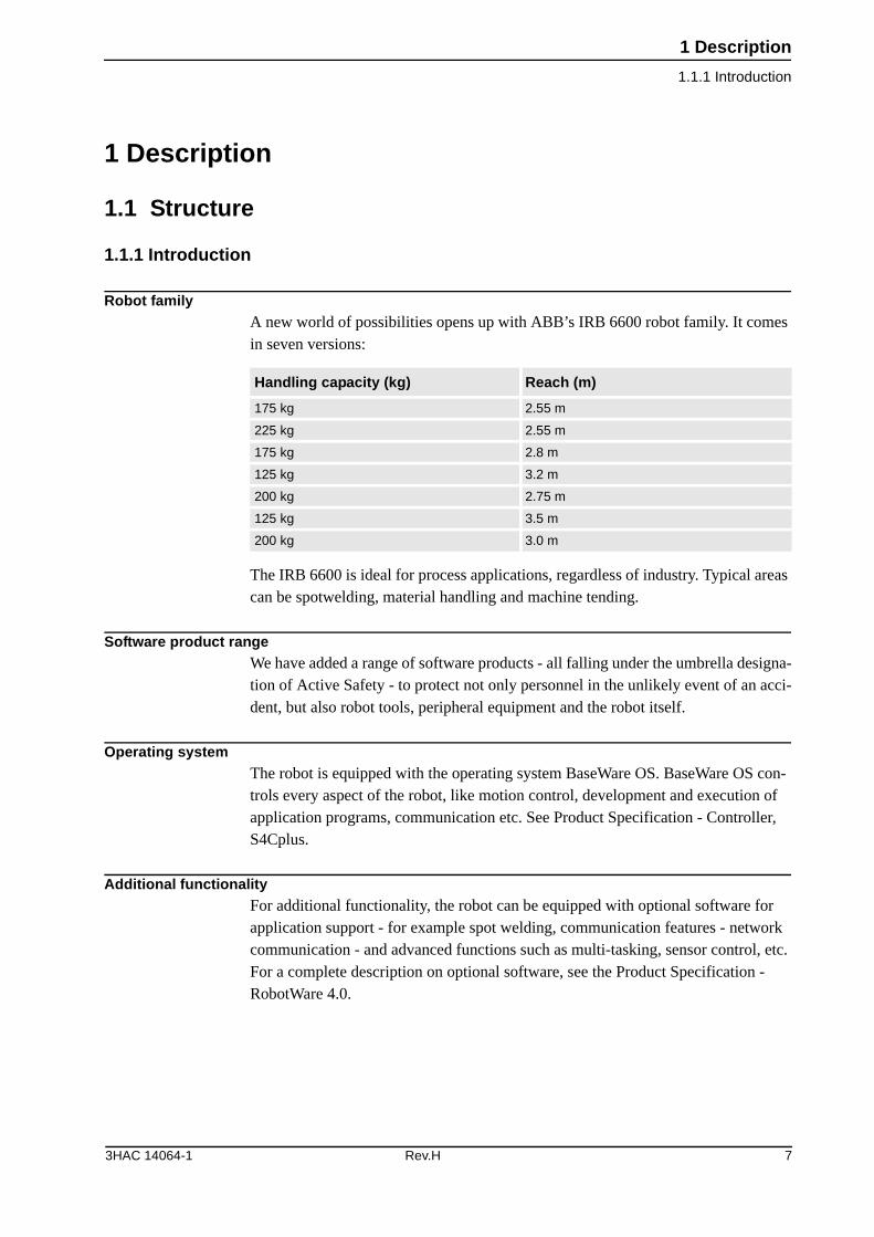
Robot familyA new world of possibilities opens up with ABB’s IRB 6600 robot family. It comes in seven versions:
The IRB 6600 is ideal for process applications, regardless of industry. Typical areas can be spotwelding, material handling and machine tending.
Software product rangeWe have added a range of software products - all falling under the umbrella designa-tion of Active Safety - to protect not only personnel in the unlikely event of an acci-dent, but also robot tools, peripheral equipment and the robot itself.
Operating systemThe robot is equipped with the operating system BaseWare OS. BaseWare OS con-trols every aspect of the robot, like motion control, development and execution of application programs, communication etc. See Product Specification - Controller, S4Cplus.
Additional functionalityFor additional functionality, the robot can be equipped with optional software for application support - for example spot welding, communication features - network communication - and advanced functions such as multi-tasking, sensor control, etc. For a complete description on optional software, see the Product Specification - RobotWare 4.0.
Handling capacity (kg) Reach (m)
175 kg 2.55 m
225 kg 2.55 m
175 kg 2.8 m
125 kg 3.2 m
200 kg 2.75 m
125 kg 3.5 m
200 kg 3.0 m
3HAC 14064-1 Rev.H 7
1 Description
1.1.2 Different robot versions
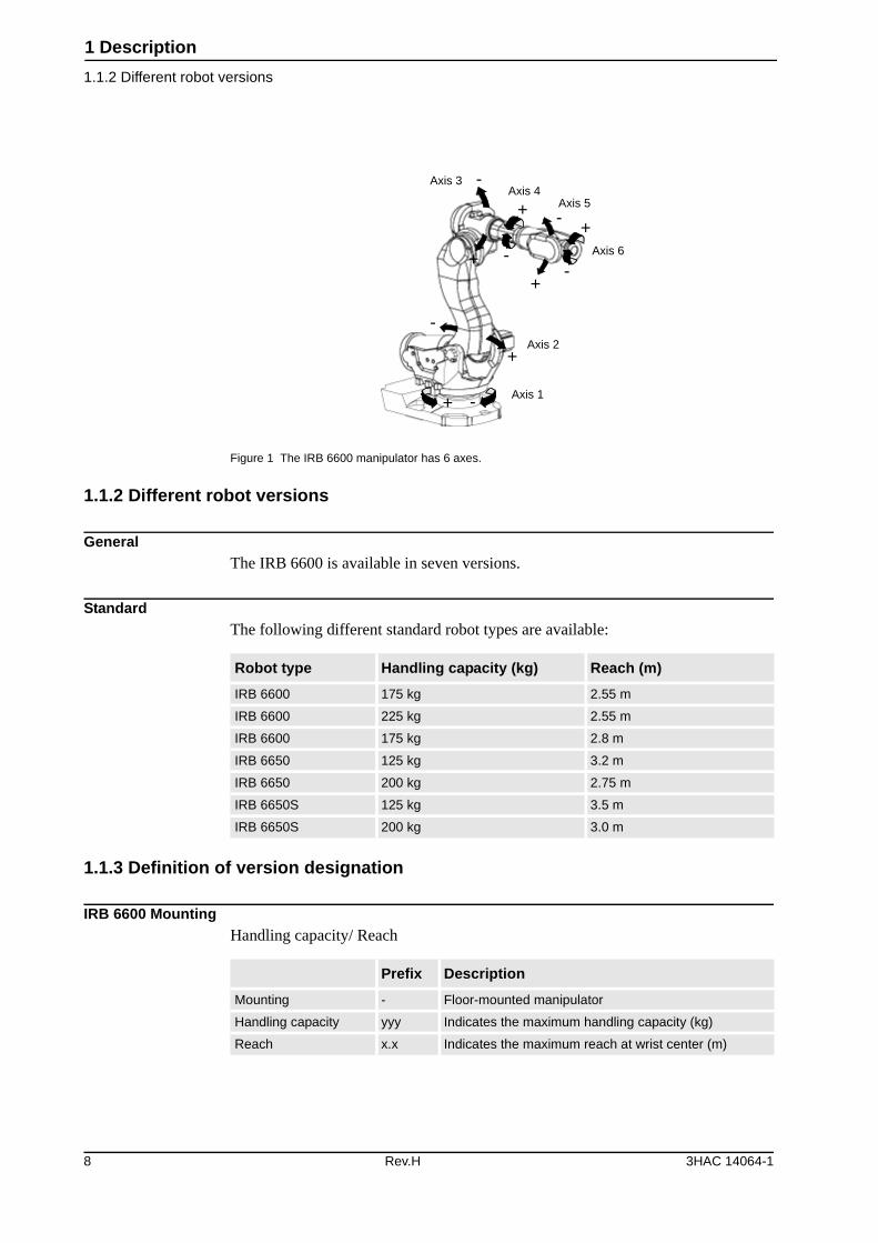
Figure 1 The IRB 6600 manipulator has 6 axes.
1.1.2 Different robot versions
GeneralThe IRB 6600 is available in seven versions.
StandardThe following different standard robot types are available:
1.1.3 Definition of version designation
IRB 6600 MountingHandling capacity/ Reach
-
-
--
-
-
++
+
+
++
Axis 3Axis 4
Axis 5
Axis 6
Axis 2
Axis 1
Robot type Handling capacity (kg) Reach (m)
IRB 6600 175 kg 2.55 m
IRB 6600 225 kg 2.55 m
IRB 6600 175 kg 2.8 m
IRB 6650 125 kg 3.2 m
IRB 6650 200 kg 2.75 m
IRB 6650S 125 kg 3.5 m
IRB 6650S 200 kg 3.0 m
Prefix Description
Mounting - Floor-mounted manipulator
Handling capacity yyy Indicates the maximum handling capacity (kg)
Reach x.x Indicates the maximum reach at wrist center (m)
8 Rev.H 3HAC 14064-1
1 Description
1.1.3 Definition of version designation
Manipulator weight
Other technical data
Power consumption at max load
Robot type Handling capacity Reach Weight
IRB 6600 175 kg 2.55 m 1700 kga
a. Without DressPack
IRB 6600 225 kg 2.55 m 1700 kga
IRB 6600 175 kg 2.8 m 1725 kga
IRB 6650 125 kg 3.2 m 1750 kga
IRB 6650 200 kg 2.75 m 1725 kga
IRB 6650S 125 kg 3.5 m 2175 kga
IRB 6650S 200 kg 3.0 m 2150 kga
Data Description Note
Airborne noise level The sound pressure level outside the working space
< 73 dB (A) Leq (acc. to Machinery directive98/37/EEC)
Type of Movement IRB 6600/ 6650 IRB 6650S
ISO Cube
Normal robot move-ments
2.6 kW
3.8 kW
2.4 kW
-
3HAC 14064-1 Rev.H 9
1 Description
1.1.3 Definition of version designation
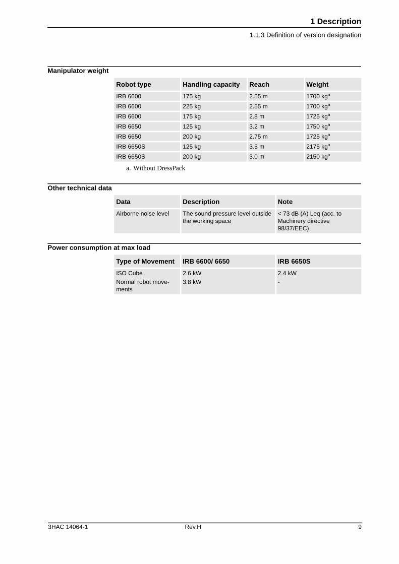
Figure 2 View of the IRB 6600 and IRB 6650 manipulator from the side and above (dimensions in mm). Allow 200 mm behind the manipulator foot for cables.
Pos Description
A R 580 for type A
R 595 for type B (front side, motor axis 2)
R 690 with fork lift
10 Rev.H 3HAC 14064-1
1 Description
1.1.3 Definition of version designation
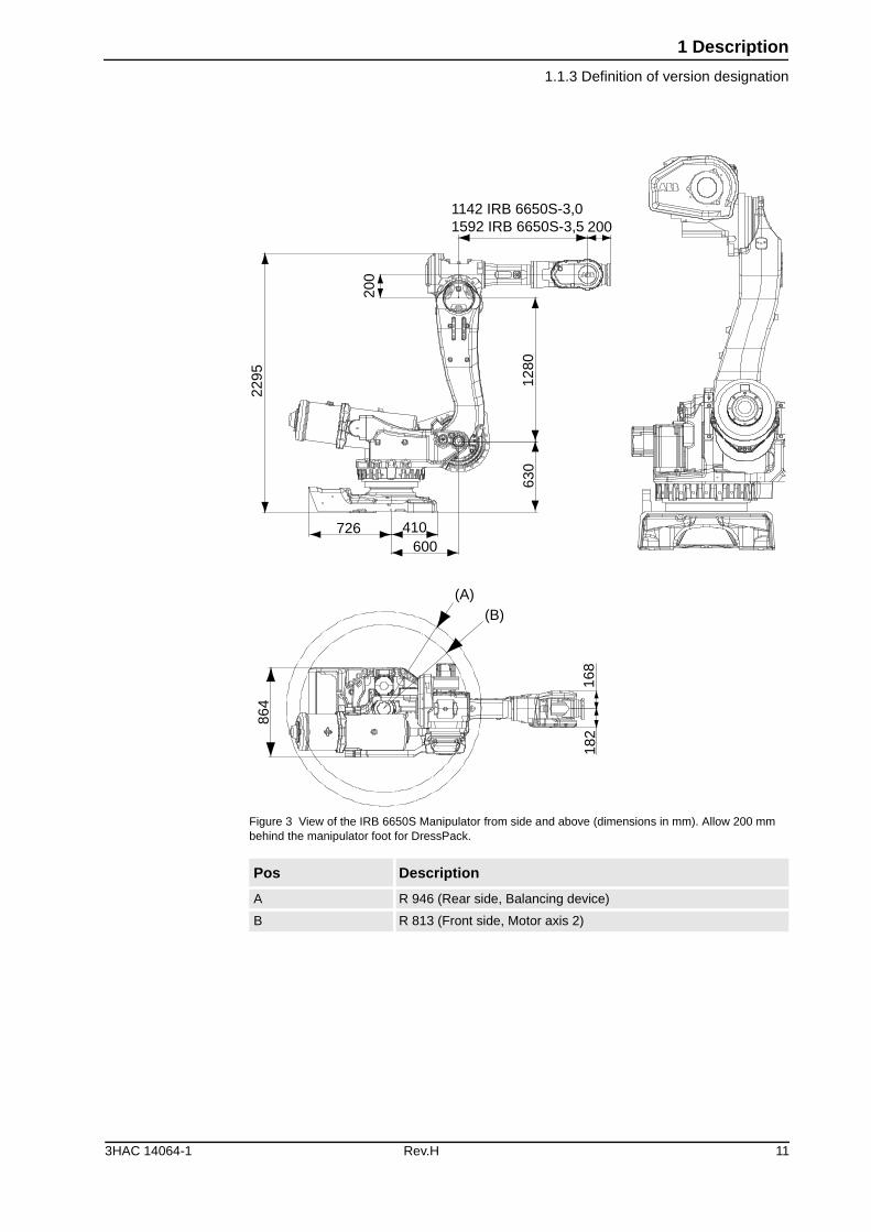
Figure 3 View of the IRB 6650S Manipulator from side and above (dimensions in mm). Allow 200 mm behind the manipulator foot for DressPack.
Pos Description
A R 946 (Rear side, Balancing device)
B R 813 (Front side, Motor axis 2)
(A)(B)
168
182
600410726
2295
200
1280
630
1142 IRB 6650S-3,01592 IRB 6650S-3,5 200
864
3HAC 14064-1 Rev.H 11
1 Description
1.2.1 Standards
1.2 Safety/Standards
1.2.1 Standards
The robot conforms to the following standards:
The robot complies fully with the health and safety standards specified in the EEC’s Machinery Directives.
The Service Information System (SIS)The service information system gathers information about the robot’s usage and determines how hard the robot is used. The usage is characterized by the speed, the rotation angles and the load of every axis.
With this data collection, the service interval of every individual robot of this gener-ation can be predicted, optimizing and planning ahead service activities. The collec-tion data is available via the teach pendant or the network link to the robot.
Standard Description
EN ISO 12100 -1 Safety of machinery, terminology
EN ISO 12100 -2 Safety of machinery, technical specifications
EN 954-1 Safety of machinery, safety related parts of control systems
EN 60204 Electrical equipment of industrial machines
EN 775 Electrical equipment of industrial machines
EN 61000-6-4 (option) EMC, Generic emission
EN 61000-6-2 EMC, Generic immunity
Standard Description
IEC 60204-1 Electrical equipment of industrial machines
IEC 60529 Degrees of protection provided by enclosures
Standard Description
ISO 10218 Manipulating industrial robots, safety
ISO 9787 Manipulating industrial robots, coordinate systems and motions
Standard Description
ANSI/RIA 15.06/1999 Safety Requirements for Industrial Robots and Robot Sys-tems.
ANSI/UL 1740-1998 (option) Safety Standard for Robots and Robotic Equipment
CAN/CSA Z 434-03 (option) Industrial Robots and Robot Systems - General Safety Requirements
12 Rev.H 3HAC 14064-1
1 Description
1.2.2 The Active Safety System
The Process Robot Generation is designed with absolute safety in mind. It is dedi-cated to actively or passively avoid collisions and offers the highest level of safety to the operators and the machines as well as the surrounding and attached equipment. These features are presented in the active and passive safety system.
1.2.2 The Active Safety System
GeneralThe active safety system includes those software features that maintain the accuracy of the robot’s path and those that actively avoid collisions which can occur if the robot leaves the programmed path accidentally or if an obstacle is put into the robot’s path.
The Active Brake System (ABS)All robots run with an active brake system that supports the robots to maintain the programmed path even in emergency situations.
The ABS is active during all stop modes, braking the robot to a stop with the power of the servo drive system along the programmed path. After a specific time the mechanical brakes are activated ensuring a safe stop.
The stopping process is in accordance with a class 1 stop. The maximal applicable torque on the most loaded axis determines the stopping distance.
In case of a failure of the drive system or a power interruption, a class 0 stop turns out. While programming the robot in manual mode, the enabling device has a class 0 stop. ES and GS still have a class 1 stop.
The Self Tuning Performance (STP)The Process Robot Generation is designed to run at different load configurations, many of which occur within the same program and cycle.
The robot’s installed electrical power can thus be exploited to lift heavy loads, create a high axis force or accelerate quickly without changing the configuration of the robot.
Consequently the robot can run in a “power mode” or a “speed mode” which can be measured in the respective cycle time of one and the same program but with different tool loads. This feature is based on QuickMoveTM.
The respective change in cycle time can be measured by running the robot in NoMo-tionExecution with different loads or with simulation tools like RobotStudio.
3HAC 14064-1 Rev.H 13
1 Description
1.2.2 The Active Safety System
The Electronically Stabilised Path (ESP)The load and inertia of the tool have a significant effect on the path performance of a robot. The Process Robot Generation is equipped with a system to electronically stabilize the robot’s path in order to achieve the best path performance.
This has an influence while accelerating and braking and consequently stabilizes the path during all motion operations with a compromise of the best cycle time. This feature is secured through TrueMoveTM.
Over-speed protectionThe speed of the robot is monitored by two independent computers.
Restricting the working spaceThe movement of each axis can be restricted using software limits.
As options there are safeguarded space stops for connecting position switches to restrict the working space for axes 1-3.
Axes 1-3 can also be restricted by means of mechanical stops.
Collision detection (option)In case of an unexpected mechanical disturbance , such as a collision, electrode stick-ing, etc., the robot will detect the collision, stop on the path and slightly back off from its stop position, releasing tension in the tool.
14 Rev.H 3HAC 14064-1
1 Description
1.2.3 The Passive Safety System
1.2.3 The Passive Safety System
GeneralThe Process Robot Generation has a dedicated passive safety system that, by hard-ware construction and dedicated solutions, is designed to avoid collisions with sur-rounding equipment. It integrates the robot system into the surrounding equipment safely.
Compact robot arm designThe shape of the lower and upper arm system is compact, avoiding interference into the working envelope of the robot.
The lower arm is shaped inward, giving more space under the upper arm to re-orien-tate large parts and leaving more working space while reaching over equipment in front of the robot.
The rear side of the upper arm is compact, with no components projecting over the edge of the robot base even when the robot is moved into the home position.
Moveable mechanical limitation of main axes (option)All main axes can be equipped with moveable mechanical stops, limiting the work-ing range of every axis individually. The mechanical stops are designed to withstand a collision even under full load.
Position switches on main axes (option)All main axes can be equipped with position switches. The double circuitry to the cam switches is designed to offer personal safety according to the respective stan-dards.
3HAC 14064-1 Rev.H 15
1 Description
1.2.4 The Internal Safety Concept
1.2.4 The Internal Safety Concept
GeneralThe internal safety concept of the Process Robot Generation is based on a two-chan-nel circuit that is continuously monitored. If any component fails, the electrical power supplied to the motors shuts off and the brakes engage.
Safety category 3Malfunction of a single component, such as a sticking relay, will be detected at the next MOTOR OFF/MOTOR ON operation. MOTOR ON is then prevented and the faulty section is indicated. This complies with category 3 of EN 954-1, Safety of machinery - safety related parts of control systems - Part 1.
Selecting the operating mode The robot can be operated either manually or automatically. In manual mode, the robot can only be operated via the teach pendant, i.e. not by any external equipment.
Reduced speedIn manual mode, the speed is limited to a maximum of 250 mm/s (600 inch/min.). The speed limitation applies not only to the TCP (Tool Center Point), but to all parts of the robot. It is also possible to monitor the speed of equipment mounted on the robot.
Three position enabling deviceThe enabling device on the teach pendant must be used to move the robot when in manual mode. The enabling device consists of a switch with three positions, meaning that all robot movements stop when either the enabling device is pushed fully in, or when it is released completely. This makes the robot safer to operate.
Safe manual movementThe robot is moved using a joystick instead of the operator having to look at the teach pendant to find the right key.
Emergency stopThere is one emergency stop push button on the controller and another on the teach pendant. Additional emergency stop buttons can be connected to the robot’s safety chain circuit.
16 Rev.H 3HAC 14064-1
1 Description
1.2.4 The Internal Safety Concept
Safeguarded space stopThe robot has a number of electrical inputs which can be used to connect external safety equipment, such as safety gates and light curtains. This allows the robot’s safety functions to be activated both by peripheral equipment and by the robot itself.
Delayed safeguarded space stopA delayed stop gives a smooth stop. The robot stops in the same way as at a normal program stop with no deviation from the programmed path. After approx. 1 second the power supplied to the motors is shut off.
Hold-to-run control“Hold-to-run” means that you must depress the start button in order to move the robot. When the button is released the robot will stop. The hold-to-run function makes program testing safer.
Fire safetyBoth the manipulator and control system comply with UL’s (Underwriters Laborato-ries Inc.) tough requirements for fire safety.
Safety lamp (option)As an option, the robot can be equipped with a safety lamp mounted on the manipu-lator. This is activated when the motors are in the MOTORS ON state.
This option is not available for S4Cplus Automotive
3HAC 14064-1 Rev.H 17
1 Description
1.3.1 Introduction
1.3 Installation
1.3.1 Introduction
GeneralAll versions of IRB 6600 are designed for floor mounting. Depending on the robot version, an end effector with max. weight of 175 to 225 kg including payload, can be mounted on the mounting flange (axis 6). See Load diagram for IRB 6600 generation robots on page 32.
Extra LoadsExtra loads (valve packages, transformers) can be mounted on the upper arm with a maximum weight of 50 kg. All versions can mount an extra load of 500 kg on the frame of axis 1. Holes for mounting extra equipment on IRB 6600/6650, see page 47.
Working RangeThe working range of axes 1-3 can be limited by mechanical stops. Position switches can be supplied on axes 1-3 to indicate the position of the manipulator.
External Mains TransformerFor mains voltage 200V and 220V an external transformer will be included.
18 Rev.H 3HAC 14064-1
1 Description
1.3.2 Operating requirements
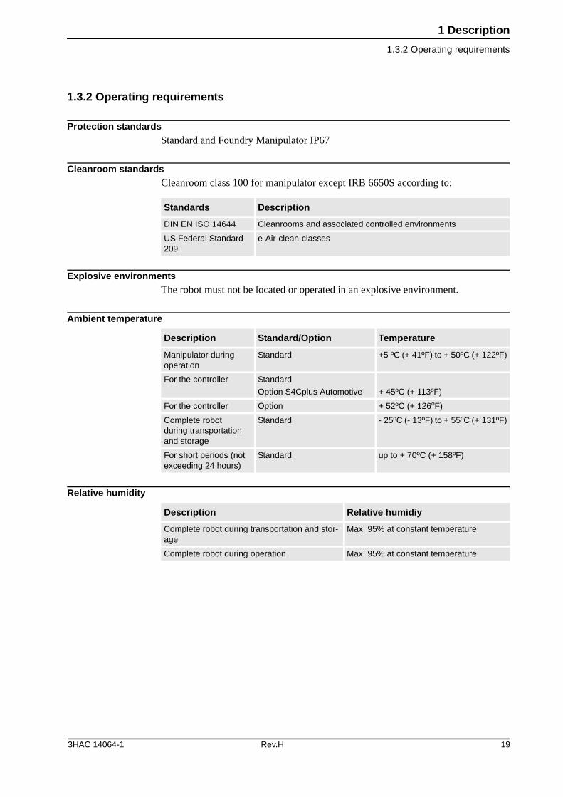
1.3.2 Operating requirements
Protection standardsStandard and Foundry Manipulator IP67
Cleanroom standardsCleanroom class 100 for manipulator except IRB 6650S according to:
Explosive environmentsThe robot must not be located or operated in an explosive environment.
Ambient temperature
Relative humidity
Standards Description
DIN EN ISO 14644 Cleanrooms and associated controlled environments
US Federal Standard 209
e-Air-clean-classes
Description Standard/Option Temperature
Manipulator during operation
Standard +5 ºC (+ 41ºF) to + 50ºC (+ 122ºF)
For the controller Standard
Option S4Cplus Automotive + 45ºC (+ 113ºF)
For the controller Option + 52ºC (+ 126oF)
Complete robot during transportation and storage
Standard - 25ºC (- 13ºF) to + 55ºC (+ 131ºF)
For short periods (not exceeding 24 hours)
Standard up to + 70ºC (+ 158ºF)
Description Relative humidiy
Complete robot during transportation and stor-age
Max. 95% at constant temperature
Complete robot during operation Max. 95% at constant temperature
3HAC 14064-1 Rev.H 19
1 Description
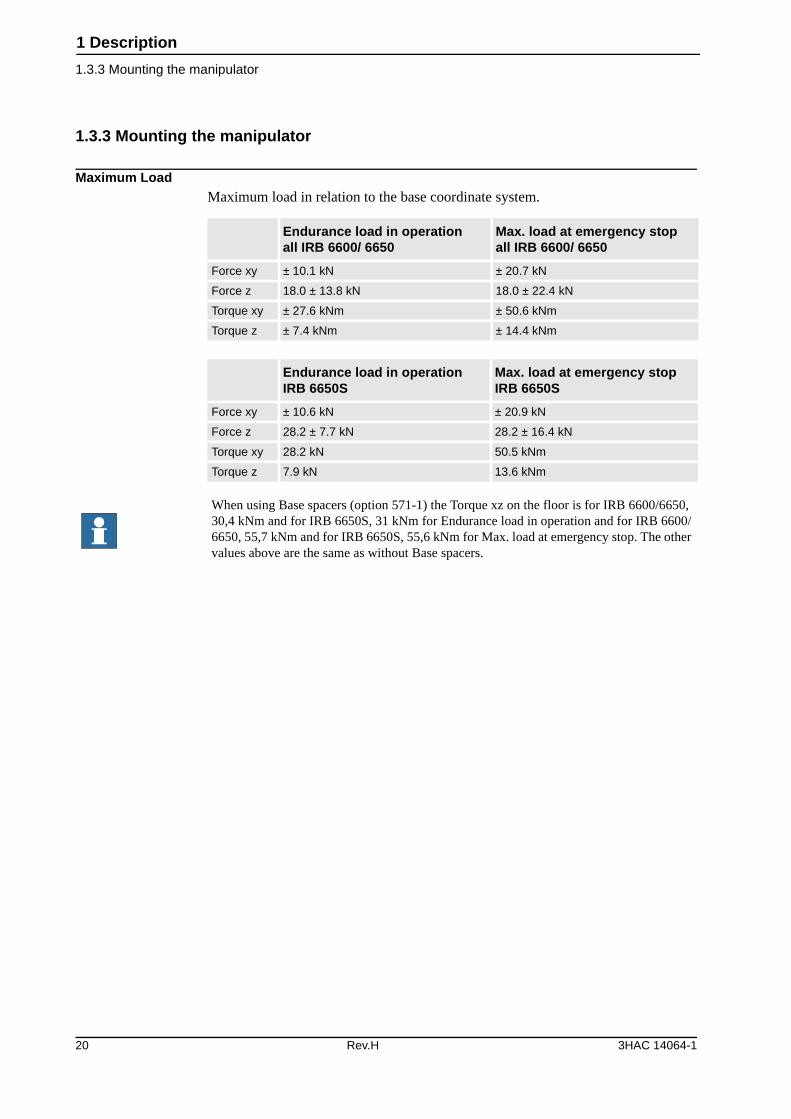
1.3.3 Mounting the manipulator
1.3.3 Mounting the manipulator
Maximum LoadMaximum load in relation to the base coordinate system.
Endurance load in operationall IRB 6600/ 6650
Max. load at emergency stopall IRB 6600/ 6650
Force xy ± 10.1 kN ± 20.7 kN
Force z 18.0 ± 13.8 kN 18.0 ± 22.4 kN
Torque xy ± 27.6 kNm ± 50.6 kNm
Torque z ± 7.4 kNm ± 14.4 kNm
Endurance load in operationIRB 6650S
Max. load at emergency stopIRB 6650S
Force xy ± 10.6 kN ± 20.9 kN
Force z 28.2 ± 7.7 kN 28.2 ± 16.4 kN
Torque xy 28.2 kN 50.5 kNm
Torque z 7.9 kN 13.6 kNm
When using Base spacers (option 571-1) the Torque xz on the floor is for IRB 6600/6650, 30,4 kNm and for IRB 6650S, 31 kNm for Endurance load in operation and for IRB 6600/6650, 55,7 kNm and for IRB 6650S, 55,6 kNm for Max. load at emergency stop. The other values above are the same as without Base spacers.
20 Rev.H 3HAC 14064-1
1 Description
1.3.3 Mounting the manipulator
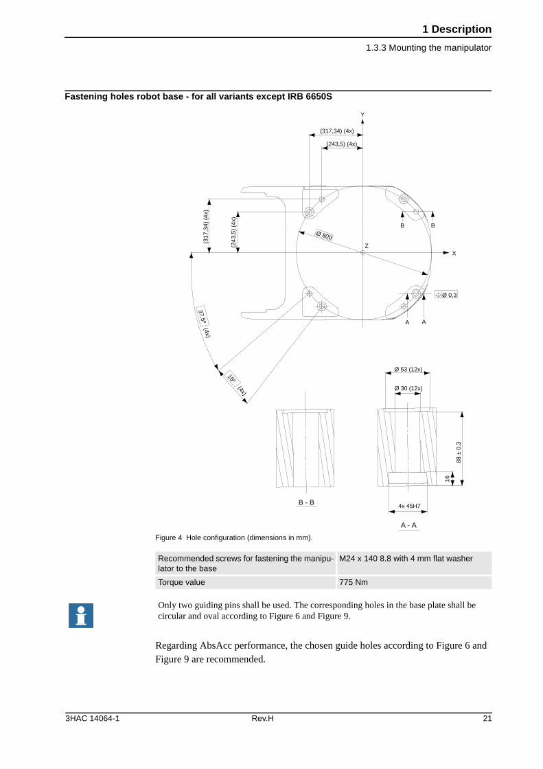
Fastening holes robot base - for all variants except IRB 6650S
Figure 4 Hole configuration (dimensions in mm).
Regarding AbsAcc performance, the chosen guide holes according to Figure 6 and Figure 9 are recommended.
Recommended screws for fastening the manipu-lator to the base
M24 x 140 8.8 with 4 mm flat washer
Torque value 775 Nm
X
BB
AA
(317,34) (4x)
(243,5) (4x)
Y
(317
,34)
(4x
)
(243
,5)
(4x)
Z
Ø 800
Ø 0,3
37,5º (4x)
15º (4x)
Ø 53 (12x)
Ø 30 (12x)
16
88 ±
0.3
4x 45H7B - B
A - A
Only two guiding pins shall be used. The corresponding holes in the base plate shall be circular and oval according to Figure 6 and Figure 9.
3HAC 14064-1 Rev.H 21
1 Description
1.3.3 Mounting the manipulator
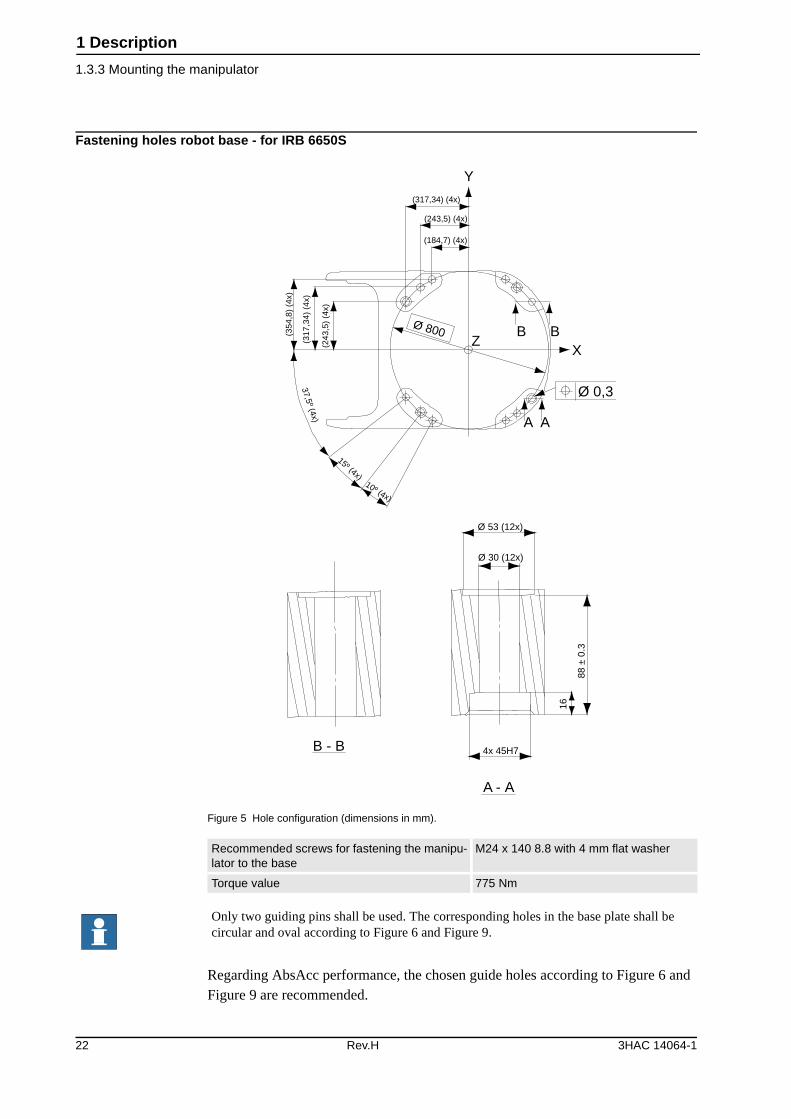
Fastening holes robot base - for IRB 6650S
Figure 5 Hole configuration (dimensions in mm).
Regarding AbsAcc performance, the chosen guide holes according to Figure 6 and Figure 9 are recommended.
Recommended screws for fastening the manipu-lator to the base
M24 x 140 8.8 with 4 mm flat washer
Torque value 775 Nm
B BX
Z
Ø 0,3
A A
10º (4x)
15º (4x)37,5º (4x)
(354
,8)
(4x)
(317
,34)
(4x
)
(243
,5)
(4x)
Ø 800
(317,34) (4x)
(243,5) (4x)
(184,7) (4x)
Y
Ø 53 (12x)
Ø 30 (12x)16
88 ±
0.3
4x 45H7B - B
A - A
Only two guiding pins shall be used. The corresponding holes in the base plate shall be circular and oval according to Figure 6 and Figure 9.
22 Rev.H 3HAC 14064-1
1 Description
1.3.3 Mounting the manipulator
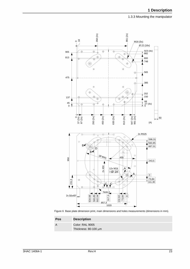
Figure 6 Base plate dimension print, main dimensions and holes measurements (dimensions in mm).
Pos Description
A Color: RAL 9005
Thickness: 80-100 �m
M16 (5x)
Ø 22 (16x)
923 (4x)882
800748
565
385
202150
6827 (4x)0
991
(2x)
947
(2x)
813
(2x)
630
(2x)
450
(2x)
293
(2x)
87 (
2x)
37 (
2x)0
045
137
0 18 358
(2x)
861
(2x)
(A)
2x R525
598,31
560,85
487,01
243,5
0
73,84111,30
0
73,8
4
132,
64
317,
3
1020857,3
502,
04
560,
85
634,
68
Note 2
2x 50x45º
12x M24
2x 4
50
231,
595
0 455(Ø 800)
475
813
905
A
AØ 1A
C C
B
BD
3HAC 14064-1 Rev.H 23
1 Description
1.3.3 Mounting the manipulator
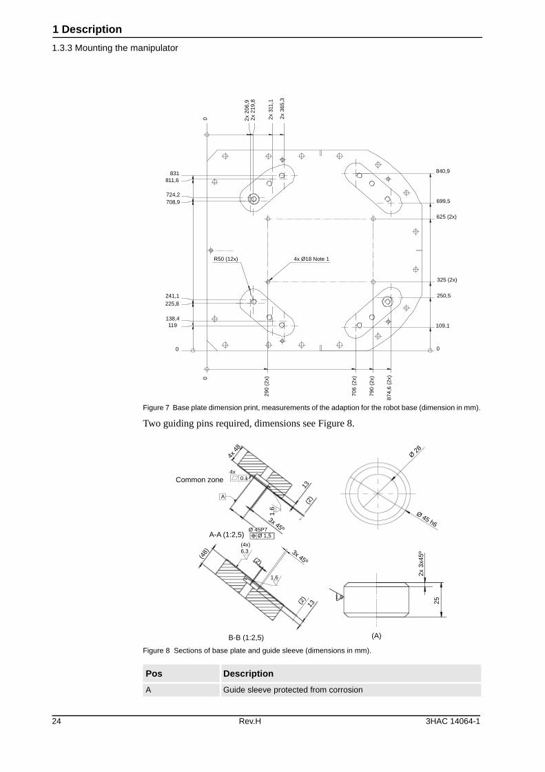
Figure 7 Base plate dimension print, measurements of the adaption for the robot base (dimension in mm).
Two guiding pins required, dimensions see Figure 8.
Figure 8 Sections of base plate and guide sleeve (dimensions in mm).
Pos Description
A Guide sleeve protected from corrosion
0 2x 2
06,9
2x 2
19,8
2x 3
11,1
2x 3
65,3
840,9
699,5
625 (2x)
325 (2x)
250,5
109,1
0
874,
6 (2
x)
790
(2x)
706
(2x)
290
(2x)0
0
119138,4
225,8241,1
R50 (12x) 4x Ø18 Note 1
708,9724,2
811,6831
Common zone
4x 4
8
13(2
)
(48)
(2)
13
1,6
3x 45º
3x 45º
A-A (1:2,5)Ø 45P7
(4x)6,3
1,6
Ø 1,5
0.1
A
(2)
4x
B-B (1:2,5)
2x 3
x45º
Ø 45 h6
25
1,6
Ø 28
(A)
24 Rev.H 3HAC 14064-1
1 Description
1.3.3 Mounting the manipulator
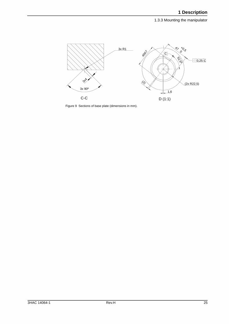
Figure 9 Sections of base plate (dimensions in mm).
3x R1
3x4
3x 90º
C-C
+0,5 47 0
0,25 C
45K7
(2x R22,5)
1,6
D (1:1)
(2)
52,5º
C
3HAC 14064-1 Rev.H 25
1 Description
1.4.1 Fine calibration
1.4 Calibration and references
1.4.1 Fine calibration
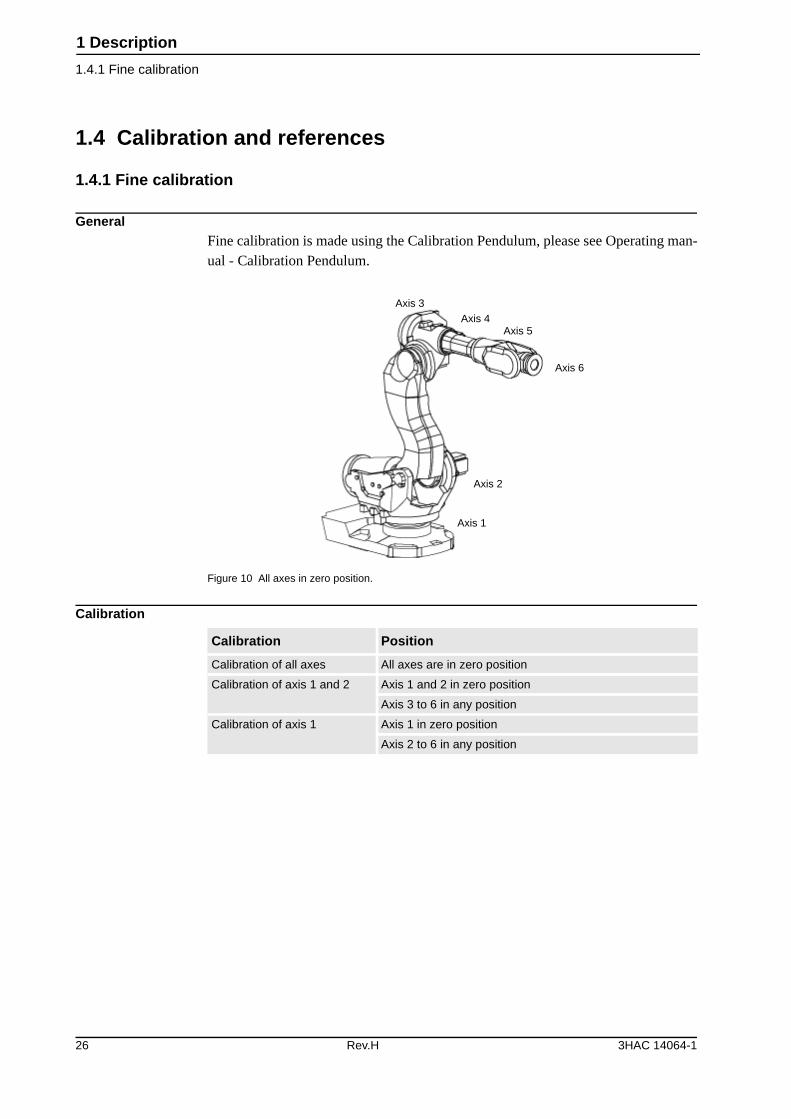
GeneralFine calibration is made using the Calibration Pendulum, please see Operating man-ual - Calibration Pendulum.
Figure 10 All axes in zero position.
Calibration
Axis 3Axis 4
Axis 5
Axis 6
Axis 2
Axis 1
Calibration Position
Calibration of all axes All axes are in zero position
Calibration of axis 1 and 2 Axis 1 and 2 in zero position
Axis 3 to 6 in any position
Calibration of axis 1 Axis 1 in zero position
Axis 2 to 6 in any position
26 Rev.H 3HAC 14064-1
1 Description
1.4.2 Absolute Accuracy calibration
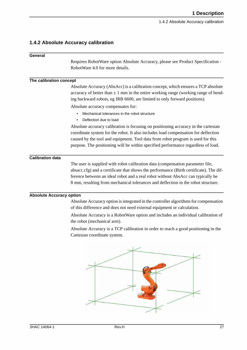
1.4.2 Absolute Accuracy calibration
GeneralRequires RobotWare option Absolute Accuracy, please see Product Specification - RobotWare 4.0 for more details.
The calibration conceptAbsolute Accuracy (AbsAcc) is a calibration concept, which ensures a TCP absolute accuracy of better than ± 1 mm in the entire working range (working range of bend-ing backward robots, eg IRB 6600, are limited to only forward positions).
Absolute accuracy compensates for:
• Mechanical tolerances in the robot structure
• Deflection due to load
Absolute accuracy calibration is focusing on positioning accuracy in the cartesian coordinate system for the robot. It also includes load compensation for deflection caused by the tool and equipment. Tool data from robot program is used for this purpose. The positioning will be within specified performance regardless of load.
Calibration dataThe user is supplied with robot calibration data (compensation parameter file, absacc.cfg) and a certificate that shows the performance (Birth certificate). The dif-ference betwenn an ideal robot and a real robot without AbsAcc can typically be 8 mm, resulting from mechanical tolerances and deflection in the robot structure.
Absolute Accuracy optionAbsolute Accuracy option is integrated in the controller algorithms for compensation of this difference and does not need external equipment or calculation.
Absolute Accuracy is a RobotWare option and includes an individual calibration of the robot (mechanical arm).
Absolute Accuracy is a TCP calibration in order to reach a good positioning in the Cartesian coordinate system.
3HAC 14064-1 Rev.H 27
1 Description
1.4.2 Absolute Accuracy calibration
Figure 11 The Cartesian coordinate system.
Production dataTypical production data regarding calibration are:
RobotPositioning accuracy (mm)
Average Max % Within 1 mm
IRB 6600 - 175/2.55
225/2.55
175/2.80
125/3.20
200/2.75
0,50 1,20 97
IRB 6650 - 125/3.20
200/2.750,50 1,20 97
IRB 6650S - 125/3.50
200/3.000,50 1,20 97
28 Rev.H 3HAC 14064-1
1 Description
1.4.3 Robot references
1.4.3 Robot references
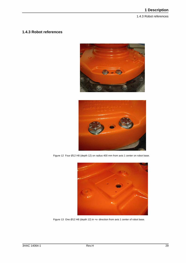
Figure 12 Four Ø12 H8 (depth 12) on radius 400 mm from axis 1 center on robot base.
Figure 13 One Ø12 H8 (depth 12) in +x- direction from axis 1 center of robot base.
3HAC 14064-1 Rev.H 29
1 Description
1.4.3 Robot references
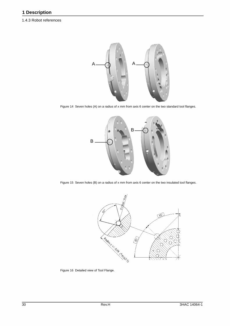
Figure 14 Seven holes (A) on a radius of x mm from axis 6 center on the two standard tool flanges.
Figure 15 Seven holes (B) on a radius of x mm from axis 6 center on the two insulated tool flanges.
Figure 16 Detailed view of Tool Flange.
A A
B
B
30 Rev.H 3HAC 14064-1
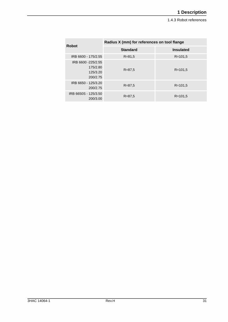
1 Description
1.4.3 Robot references
RobotRadius X (mm) for references on tool flange
Standard Insulated
IRB 6600 - 175/2.55 R=81,5 R=101,5
IRB 6600 -225/2.55
175/2.80
125/3.20
200/2.75
R=87,5 R=101,5
IRB 6650 - 125/3.20
200/2.75R=87,5 R=101,5
IRB 6650S - 125/3.50
200/3.00R=87,5 R=101,5
3HAC 14064-1 Rev.H 31
1 Description
1.5.1 Introduction
1.5 Load diagrams
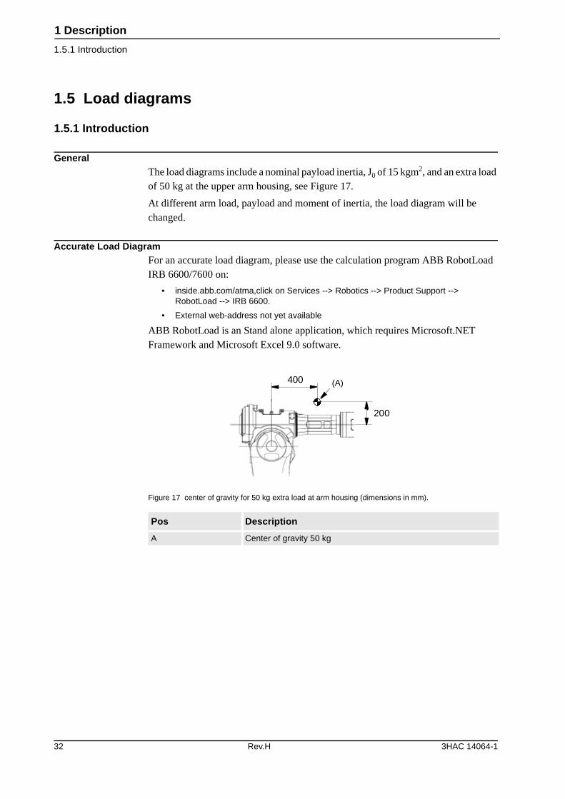
1.5.1 Introduction
GeneralThe load diagrams include a nominal payload inertia, J0 of 15 kgm2, and an extra load of 50 kg at the upper arm housing, see Figure 17.
At different arm load, payload and moment of inertia, the load diagram will be changed.
Accurate Load DiagramFor an accurate load diagram, please use the calculation program ABB RobotLoad IRB 6600/7600 on:
• inside.abb.com/atma,click on Services --> Robotics --> Product Support -->RobotLoad --> IRB 6600.
• External web-address not yet available
ABB RobotLoad is an Stand alone application, which requires Microsoft.NET Framework and Microsoft Excel 9.0 software.
Figure 17 center of gravity for 50 kg extra load at arm housing (dimensions in mm).
Pos Description
A Center of gravity 50 kg
400
200
(A)
32 Rev.H 3HAC 14064-1
1 Description
1.5.2 Diagrams
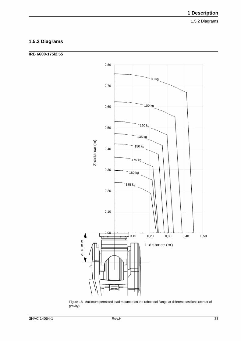
1.5.2 Diagrams
IRB 6600-175/2.55
Figure 18 Maximum permitted load mounted on the robot tool flange at different positions (center of gravity).
0,00
0,10
0,20
0,30
0,40
0,50
0,60
0,70
0,80
L-distance (m)
185 kg
180 kg
175 kg
150 kg
135 kg
120 kg
100 kg
80 kgm
m0
02
0,10 0,20 0,30 0,40 0,50
Z-d
ista
nce
(m)
3HAC 14064-1 Rev.H 33
1 Description
1.5.2 Diagrams
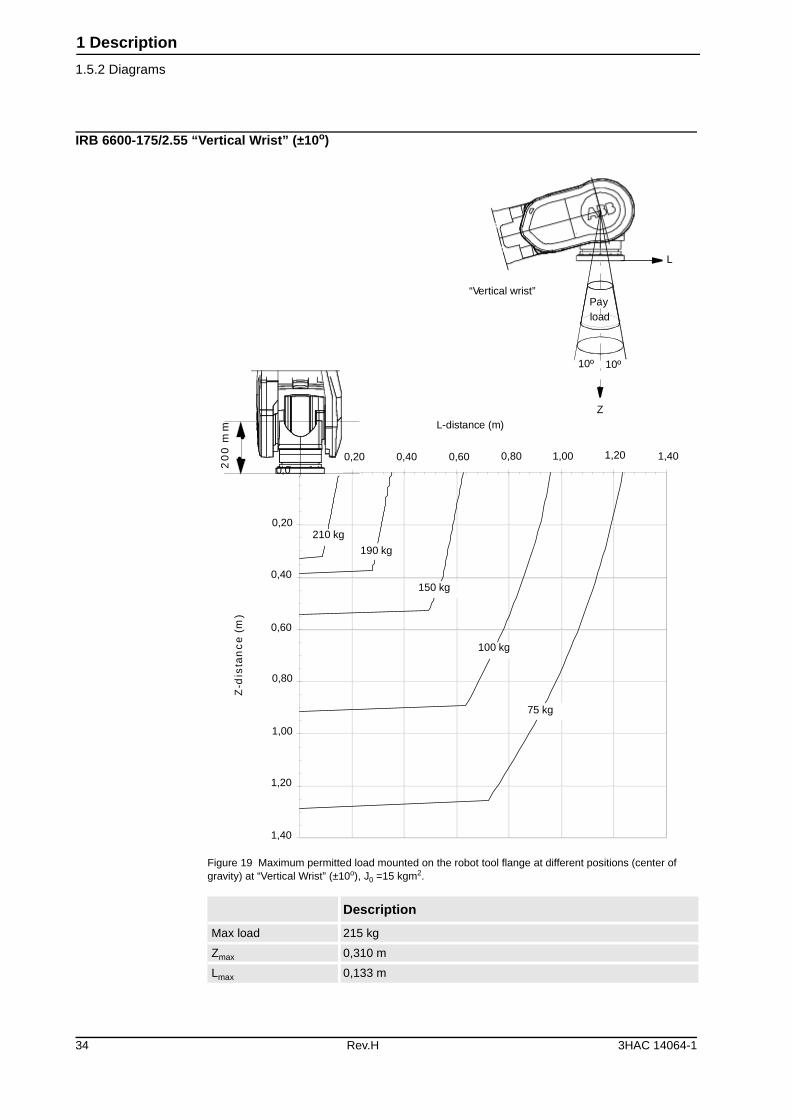
IRB 6600-175/2.55 “Vertical Wrist” (±10o)
Figure 19 Maximum permitted load mounted on the robot tool flange at different positions (center of gravity) at “Vertical Wrist” (±10o), J0 =15 kgm2.
Description
Max load 215 kg
Zmax 0,310 m
Lmax 0,133 m
0,0
150 kg
210 kg
100 kg
mm
00
2
0,20
0,40
0,80
1,20
1,40
L-distance (m)
)m(
ec
nat
sid-
Z
1,00
0,60
Payload
Z
“Vertical wrist”
L
75 kg
190 kg
1,401,201,000,800,600,400,20
10º 10º
34 Rev.H 3HAC 14064-1
1 Description
1.5.2 Diagrams
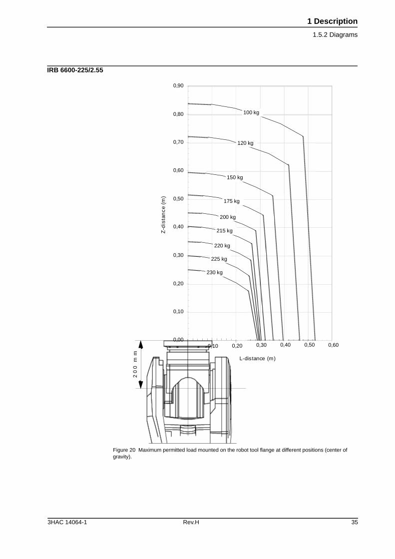
IRB 6600-225/2.55
Figure 20 Maximum permitted load mounted on the robot tool flange at different positions (center of gravity).
0,00
0,10
0,20
0,30
0,40
0,50
0,60
0,70
0,80
0,90
L-distance (m)
)m(
ec
natsid-
Z
175 kg
150 kg
120 kg
100 kg
200 kg
215 kg
225 kg
230 kg
220 kg
mm
00
2
0,10 0,20 0,30 0,40 0,50 0,60
3HAC 14064-1 Rev.H 35
1 Description
1.5.2 Diagrams
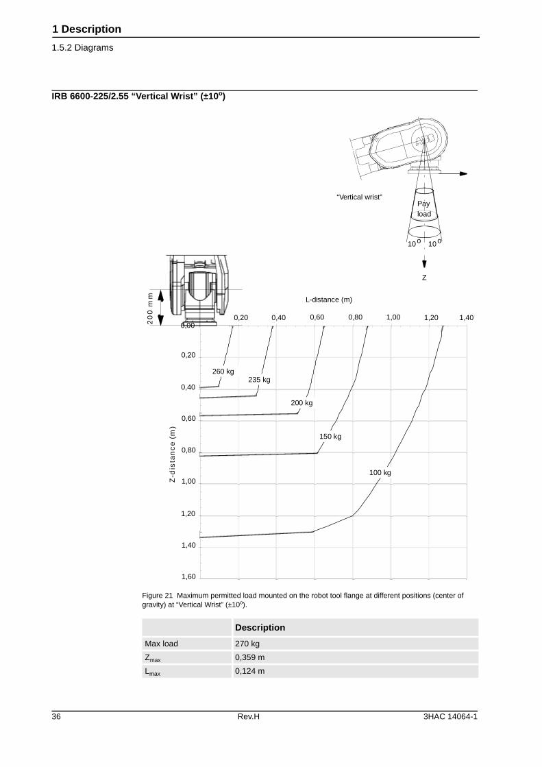
IRB 6600-225/2.55 “Vertical Wrist” (±10o)
Figure 21 Maximum permitted load mounted on the robot tool flange at different positions (center of gravity) at “Vertical Wrist” (±10o).
Description
Max load 270 kg
Zmax 0,359 m
Lmax 0,124 m
0,00
L-distance (m)
)m(
ec
nat
sid-
Z
100 kg
mm
00
2
150 kg
200 kg
235 kg260 kg
Payload
10o 10o
Z
“Vertical wrist”
0,20 0,40 0,60 0,80 1,00 1,20 1,40
0,20
0,40
0,60
0,80
1,00
1,20
1,40
1,60
36 Rev.H 3HAC 14064-1
1 Description
1.5.2 Diagrams
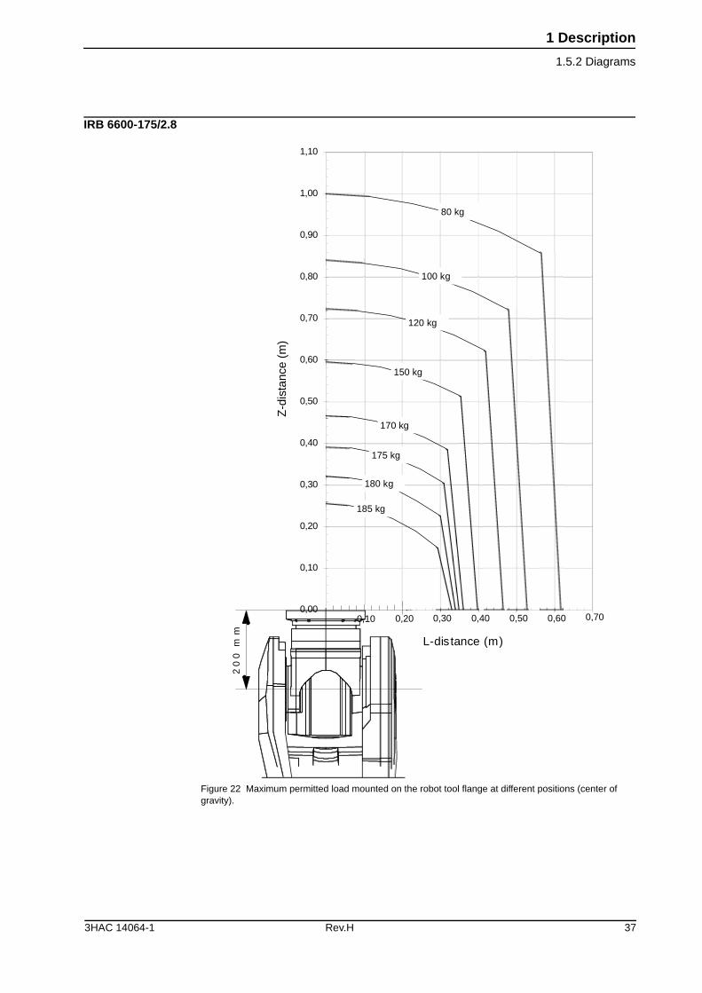
IRB 6600-175/2.8
Figure 22 Maximum permitted load mounted on the robot tool flange at different positions (center of gravity).
0,00
0,10
0,20
0,30
0,40
0,50
0,60
0,70
0,80
0,90
1,00
1,10
L-distance (m)
80 kg
100 kg
120 kg
150 kg
170 kg
175 kg
180 kg
185 kg
mm
00
2
0,10 0,20 0,30 0,40 0,50 0,60 0,70
Z-d
ista
nce
(m)
3HAC 14064-1 Rev.H 37
1 Description
1.5.2 Diagrams
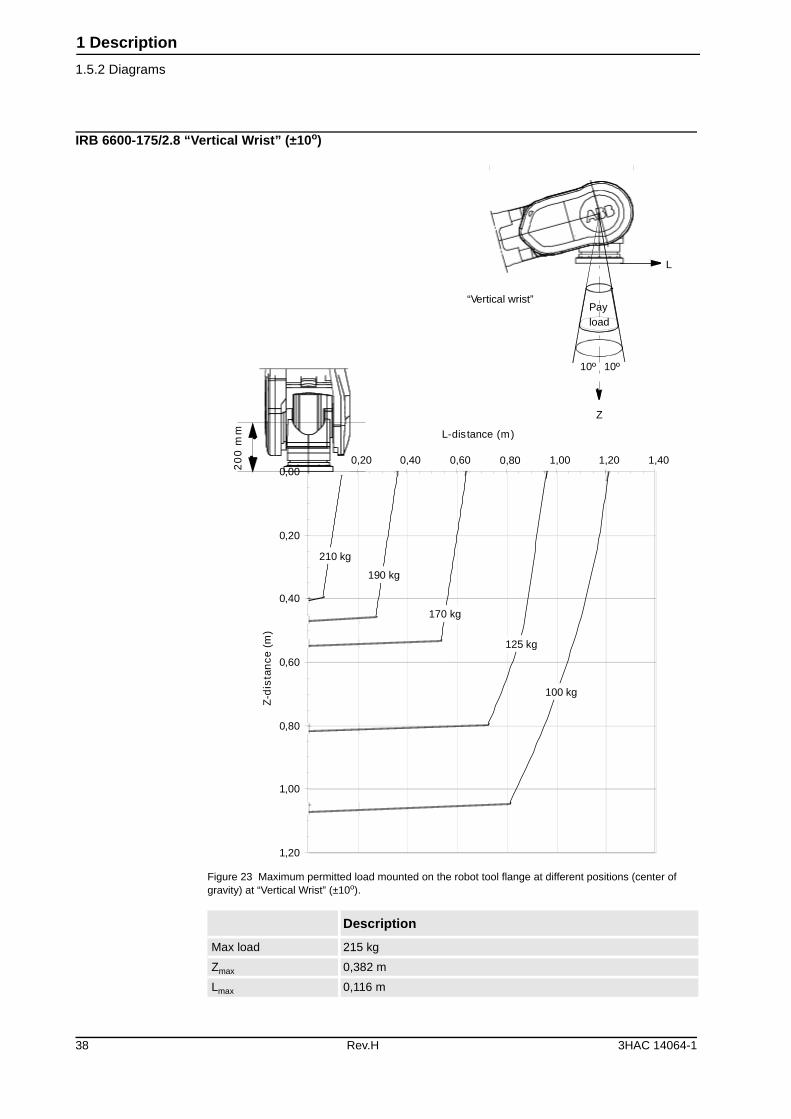
IRB 6600-175/2.8 “Vertical Wrist” (±10o)
Figure 23 Maximum permitted load mounted on the robot tool flange at different positions (center of gravity) at “Vertical Wrist” (±10o).
Description
Max load 215 kg
Zmax 0,382 m
Lmax 0,116 m
0,00
0,20
0,40
0,60
0,80
1,00
1,20
L-distance (m)
)m(
ecnat
sid-
Z
170 kg
mm
00
2
125 kg
190 kg
210 kg
100 kg
Payload
Z
L
“Vertical wrist”
0,20 0,40 0,60 0,80 1,00 1,20 1,40
10º10º
38 Rev.H 3HAC 14064-1
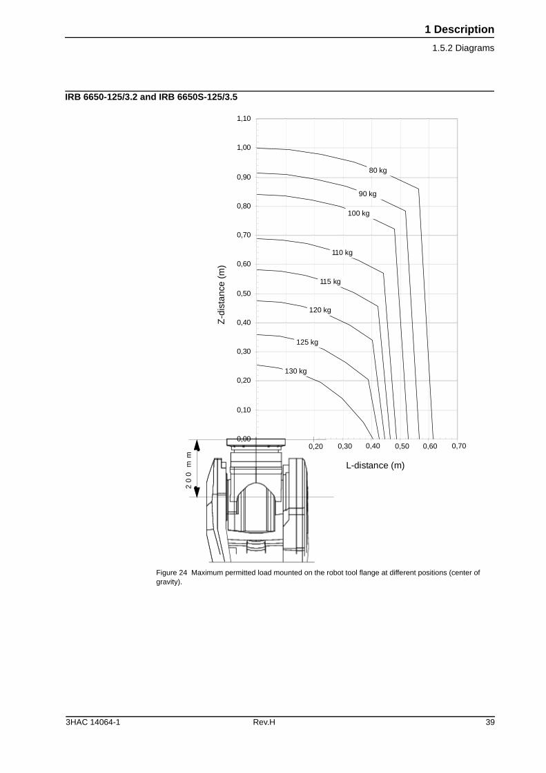
1 Description
1.5.2 Diagrams
IRB 6650-125/3.2 and IRB 6650S-125/3.5
Figure 24 Maximum permitted load mounted on the robot tool flange at different positions (center of gravity).
0,00
0,10
0,20
0,30
0,40
0,50
0,60
0,70
0,80
0,90
1,00
1,10
mm
00
2
L-distance (m)
100 kg
110 kg
115 kg
120 kg
125 kg
130 kg
80 kg
90 kg
0,20 0,30 0,40 0,50 0,60 0,70
Z-d
ista
nce
(m)
3HAC 14064-1 Rev.H 39
1 Description
1.5.2 Diagrams
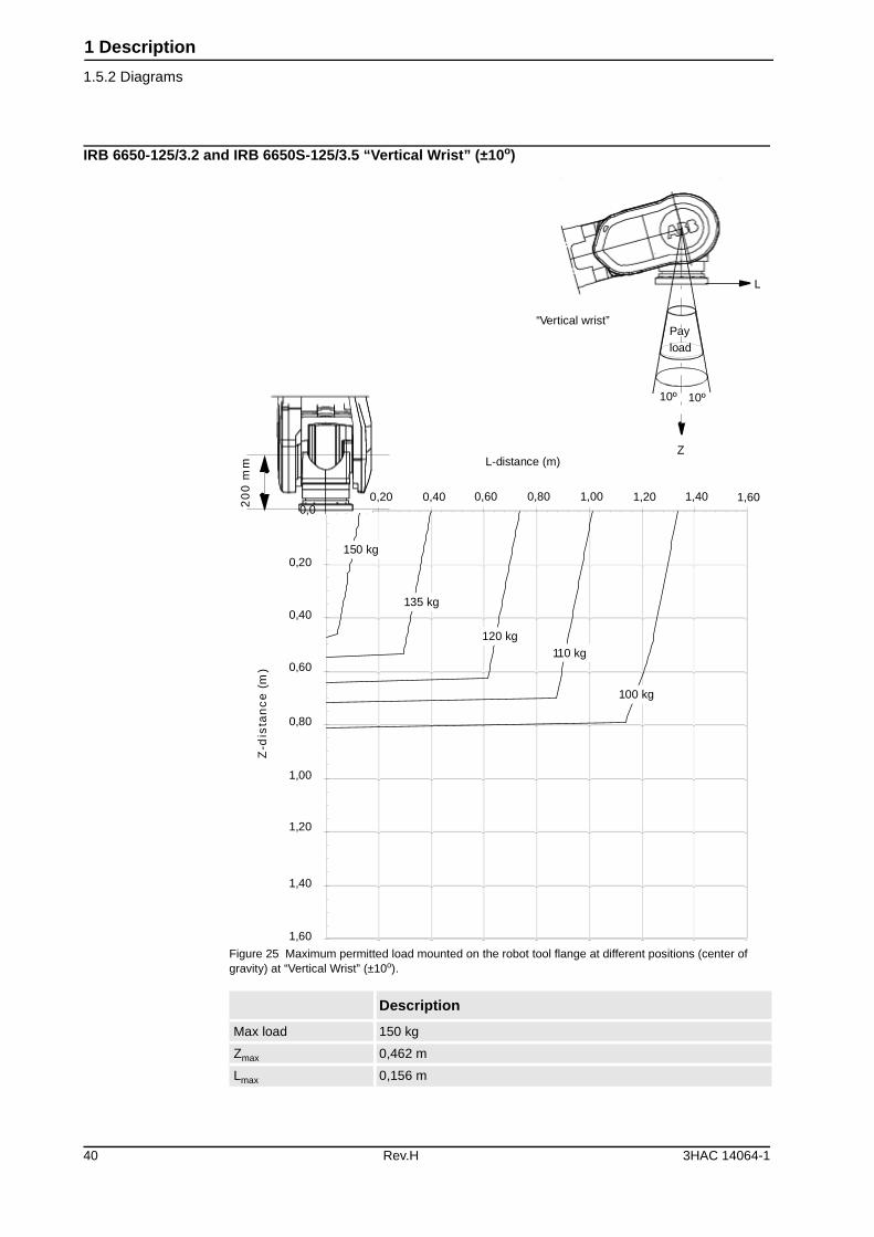
IRB 6650-125/3.2 and IRB 6650S-125/3.5 “Vertical Wrist” (±10o)
Figure 25 Maximum permitted load mounted on the robot tool flange at different positions (center of gravity) at “Vertical Wrist” (±10o).
Description
Max load 150 kg
Zmax 0,462 m
Lmax 0,156 m
0,0
1,60
0,20
0,40
0,80
1,20
1,40
1,00
0,60
150 kg
Payload
Z
L
135 kg
120 kg110 kg
100 kg
mm
00
2
L-distance (m)
)m(
ec
nat
sid-
Z
“Vertical wrist”
0,20 0,40 0,60 0,80 1,00 1,20 1,40 1,60
10º 10º
40 Rev.H 3HAC 14064-1
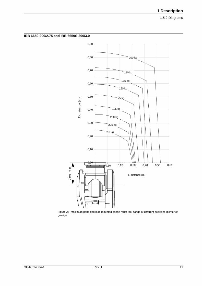
1 Description
1.5.2 Diagrams
IRB 6650-200/2.75 and IRB 6650S-200/3.0
Figure 26 Maximum permitted load mounted on the robot tool flange at different positions (center of gravity).
0,00
0,10
0,20
0,30
0,40
0,50
0,60
0,70
0,80
0,90
100 kg
mm
00
2
L-distance (m)
)m(
ec
nat
sid-
Z
120 kg
135 kg
150 kg
175 kg
195 kg
200 kg
205 kg
210 kg
0,10 0,20 0,30 0,40 0,50 0,60
3HAC 14064-1 Rev.H 41
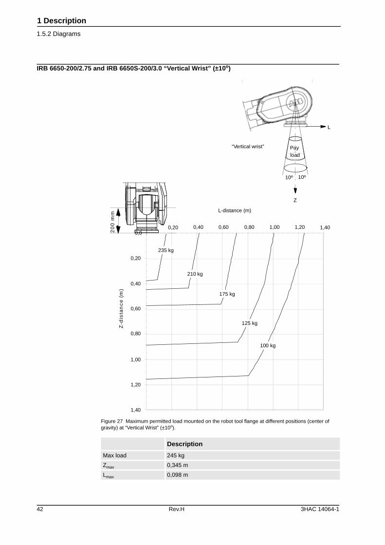
1 Description
1.5.2 Diagrams
IRB 6650-200/2.75 and IRB 6650S-200/3.0 “Vertical Wrist” (±10o)
Figure 27 Maximum permitted load mounted on the robot tool flange at different positions (center of gravity) at “Vertical Wrist” (±10o).
Description
Max load 245 kg
Zmax 0,345 m
Lmax 0,098 m
0,0
0,20
0,40
0,80
1,20
1,40
1,00
0,60
L-distance (m)
)m(
ec
nat
sid-
Z
Payload
Z
L
235 kg
210 kg
175 kg
125 kg
100 kg
“Vertical wrist”
mm
00
2
0,20 0,40 0,60 0,80 1,00 1,20 1,40
10º 10º
42 Rev.H 3HAC 14064-1
1 Description
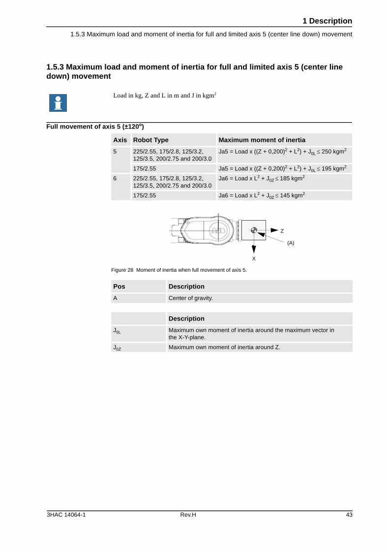
1.5.3 Maximum load and moment of inertia for full and limited axis 5 (center line down) movement
1.5.3 Maximum load and moment of inertia for full and limited axis 5 (center line down) movement
Full movement of axis 5 (±120o)
Figure 28 Moment of inertia when full movement of axis 5.
Load in kg, Z and L in m and J in kgm2
Axis Robot Type Maximum moment of inertia
5 225/2.55, 175/2.8, 125/3.2,125/3.5, 200/2.75 and 200/3.0
Ja5 = Load x ((Z + 0,200)2 + L2) + J0L � 250 kgm2
175/2.55 Ja5 = Load x ((Z + 0,200)2 + L2) + J0L � 195 kgm2
6 225/2.55, 175/2.8, 125/3.2,125/3.5, 200/2.75 and 200/3.0
Ja6 = Load x L2 + J0Z ��185 kgm2
175/2.55 Ja6 = Load x L2 + J0Z � 145 kgm2
Pos Description
A Center of gravity.
Description
J0L Maximum own moment of inertia around the maximum vector inthe X-Y-plane.
J0Z Maximum own moment of inertia around Z.
Z
X
(A)
3HAC 14064-1 Rev.H 43
1 Description
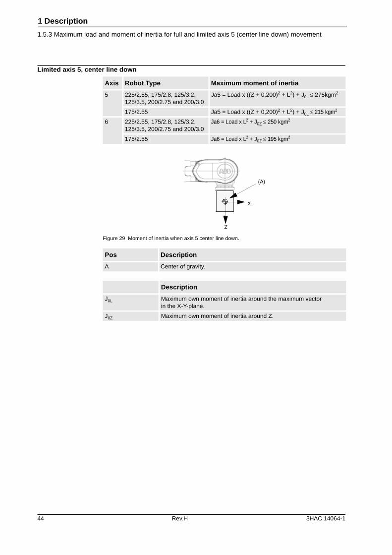
1.5.3 Maximum load and moment of inertia for full and limited axis 5 (center line down) movement
Limited axis 5, center line down
Figure 29 Moment of inertia when axis 5 center line down.
Axis Robot Type Maximum moment of inertia
5 225/2.55, 175/2.8, 125/3.2,125/3.5, 200/2.75 and 200/3.0
Ja5 = Load x ((Z + 0,200)2 + L2) + J0L � 275kgm2
175/2.55 Ja5 = Load x ((Z + 0,200)2 + L2) + J0L � 215 kgm2
6 225/2.55, 175/2.8, 125/3.2,125/3.5, 200/2.75 and 200/3.0
Ja6 = Load x L2 + J0Z � 250 kgm2
175/2.55 Ja6 = Load x L2 + J0Z � 195 kgm2
Pos Description
A Center of gravity.
Description
J0L Maximum own moment of inertia around the maximum vectorin the X-Y-plane.
J0Z Maximum own moment of inertia around Z.
Z
X
(A)
44 Rev.H 3HAC 14064-1
1 Description
1.5.4 Mounting equipment
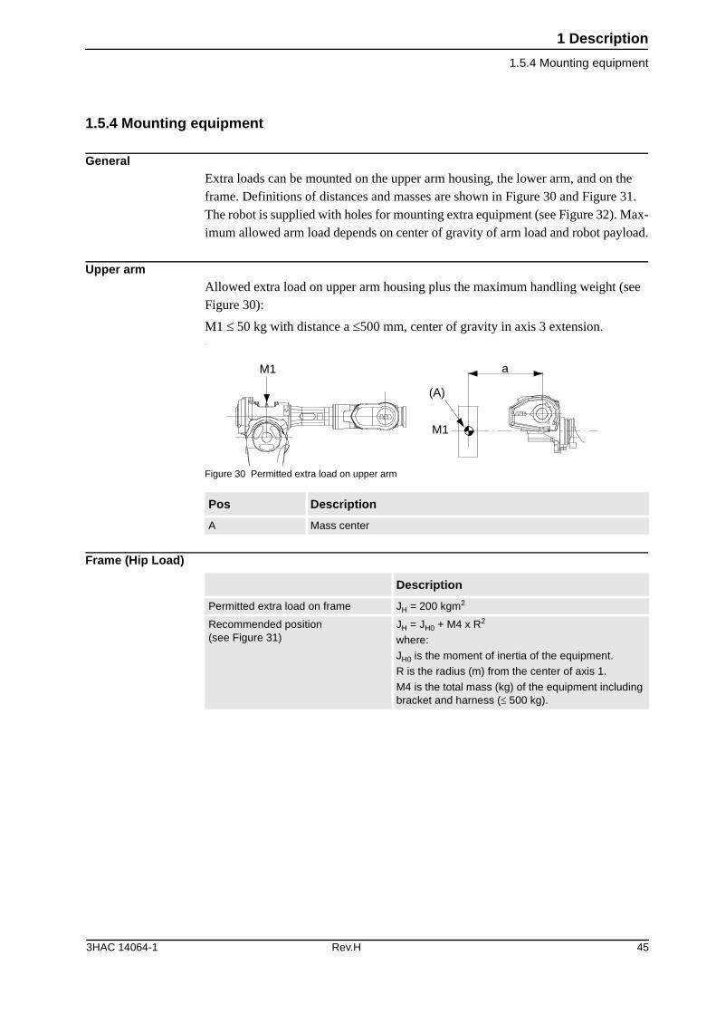
1.5.4 Mounting equipment
GeneralExtra loads can be mounted on the upper arm housing, the lower arm, and on the frame. Definitions of distances and masses are shown in Figure 30 and Figure 31. The robot is supplied with holes for mounting extra equipment (see Figure 32). Max-imum allowed arm load depends on center of gravity of arm load and robot payload.
Upper arm Allowed extra load on upper arm housing plus the maximum handling weight (see Figure 30):
M1 � 50 kg with distance a �500 mm, center of gravity in axis 3 extension. /
Figure 30 Permitted extra load on upper arm
Frame (Hip Load)
Pos Description
A Mass center
(A)
M1
M1 a
Description
Permitted extra load on frame JH = 200 kgm2
Recommended position(see Figure 31)
JH = JH0 + M4 x R2
where:
JH0 is the moment of inertia of the equipment.
R is the radius (m) from the center of axis 1.
M4 is the total mass (kg) of the equipment including bracket and harness (� 500 kg).
3HAC 14064-1 Rev.H 45
1 Description
1.5.4 Mounting equipment
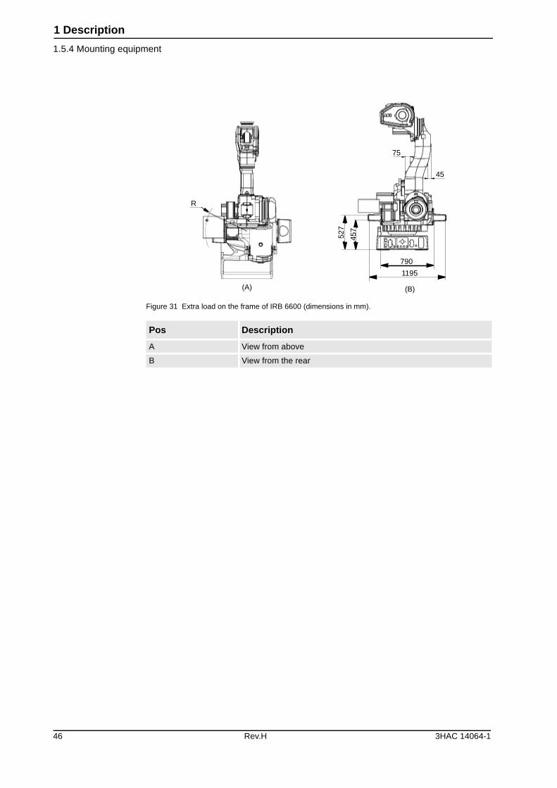
Figure 31 Extra load on the frame of IRB 6600 (dimensions in mm).
Pos Description
A View from above
B View from the rear
45
75
790
1195
(B)(A)
527
457
R
46 Rev.H 3HAC 14064-1
1 Description
1.5.5 Mounting of hip load
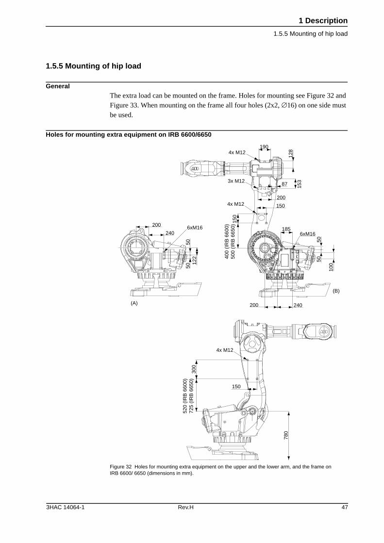
1.5.5 Mounting of hip load
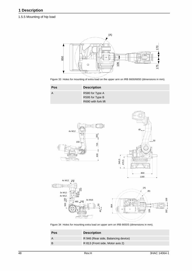
GeneralThe extra load can be mounted on the frame. Holes for mounting see Figure 32 and Figure 33. When mounting on the frame all four holes (2x2, �16) on one side must be used.
Holes for mounting extra equipment on IRB 6600/6650
Figure 32 Holes for mounting extra equipment on the upper and the lower arm, and the frame on IRB 6600/ 6650 (dimensions in mm).
200 240
1856xM16
5050
100
(B)
200
240
5050
122
6xM16
(A)
1904x M12
3x M12
200
150
87 153
4x M12
150
400
(IR
B 6
600)
500
(IR
B 6
650)
128
4x M12
150
300
520
(IR
B 6
600)
725
(IR
B 6
650)
780
3HAC 14064-1 Rev.H 47
1 Description
1.5.5 Mounting of hip load
Figure 33 Holes for mounting of extra load on the upper arm on IRB 6600/6650 (dimensions in mm).
Figure 34 Holes for mounting extra load on upper arm on IRB 6650S (dimensions in mm).
Pos Description
A R580 for Type A
R595 for Type B
R690 with fork lift
Pos Description
A R 946 (Rear side, Balancing device)
B R 813 (Front side, Motor axis 2)
850
106
170
175
(A)
4x M12 190
3x M12
4x M12
153
87220150
150
500
480 2404x M16
5040
4x M12
150
630
725
300
45
30
800
1180
540,
5
470,
5
(B)
(A)
106
168
182
864
48 Rev.H 3HAC 14064-1
1 Description
1.5.5 Mounting of hip load
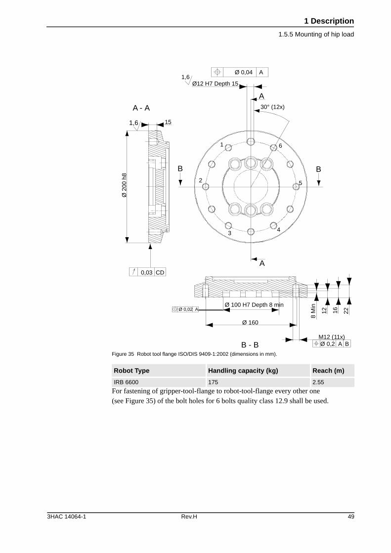
Figure 35 Robot tool flange ISO/DIS 9409-1:2002 (dimensions in mm).
For fastening of gripper-tool-flange to robot-tool-flange every other one(see Figure 35) of the bolt holes for 6 bolts quality class 12.9 shall be used.
Robot Type Handling capacity (kg) Reach (m)
IRB 6600 175 2.55
1,6
2
1
34
5
6
Ø 2
00 h
815
1,6Ø12 H7 Depth 15
Ø 0,04 A
30° (12x)
Ø 100 H7 Depth 8 min
Ø 160
M12 (11x)Ø 0,2 A B
221612
8 M
in
0,03 CD
Ø 0,02 A
B B
A
A
B - B
A - A
3HAC 14064-1 Rev.H 49
1 Description
1.5.5 Mounting of hip load
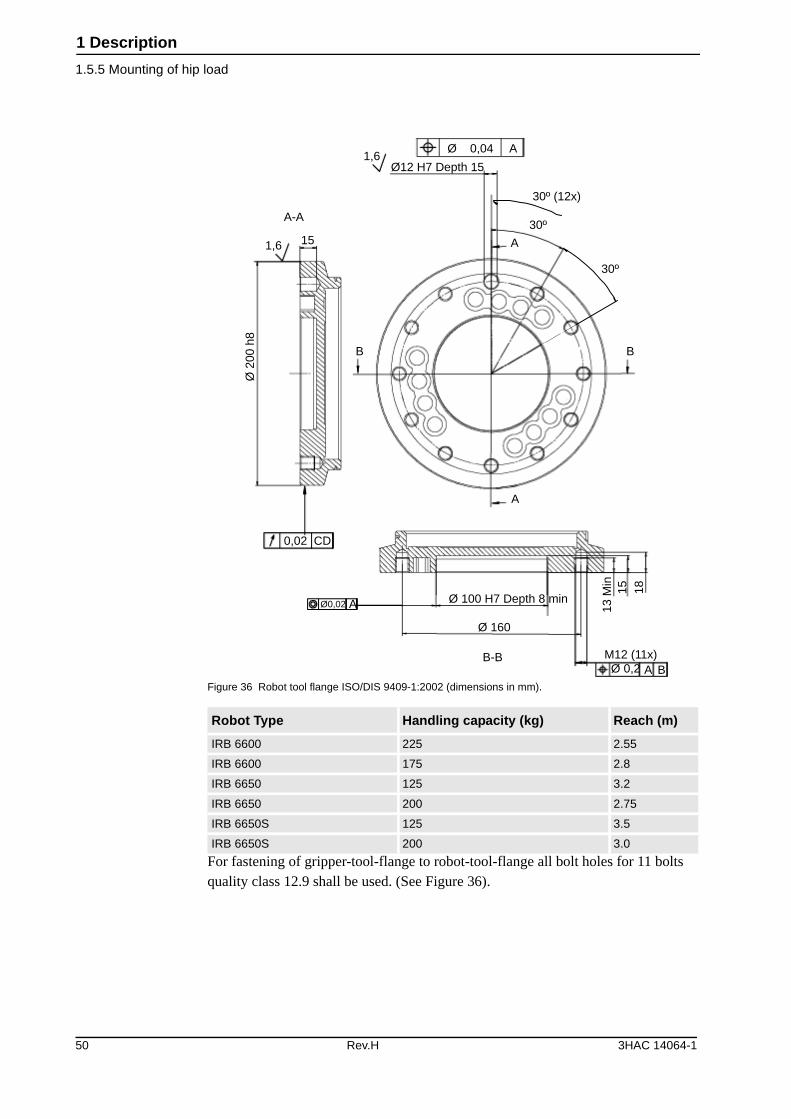
Figure 36 Robot tool flange ISO/DIS 9409-1:2002 (dimensions in mm).
For fastening of gripper-tool-flange to robot-tool-flange all bolt holes for 11 bolts quality class 12.9 shall be used. (See Figure 36).
Robot Type Handling capacity (kg) Reach (m)
IRB 6600 225 2.55
IRB 6600 175 2.8
IRB 6650 125 3.2
IRB 6650 200 2.75
IRB 6650S 125 3.5
IRB 6650S 200 3.0
Ø 2
00 h
81,6
A-A
15
B
A
A
1,6Ø 0,04 A
30º (12x)
30º
30º
B
Ø 100 H7 Depth 8 min
Ø 160
B-B M12 (11x)Ø 0,2 A B
13 M
in15 18
Ø0,02 A
0,02 CD
Ø12 H7 Depth 15
50 Rev.H 3HAC 14064-1
1 Description
1.6.1 Introduction
1.6 Maintenance and Troubleshooting
1.6.1 Introduction
GeneralThe robot requires only minimum maintenance during operation. It has been designed to make it as easy to service as possible:
• Maintenance-free AC motors are used.
• Oil is used for the gear boxes.
• The cabling is routed for longevity, and in the unlikely event of a failure, its modular design makes it easy to change.
MaintenanceThe following maintenance is required:
• Changing filter for the transformer/drive unit cooling every year.
• Changing batteries every third year.
The maintenance intervals depend on the use of the robot. For detailed information on maintenance procedures, see Maintenance section in the Product Manual.
3HAC 14064-1 Rev.H 51
1 Description
1.7.1 Introduction
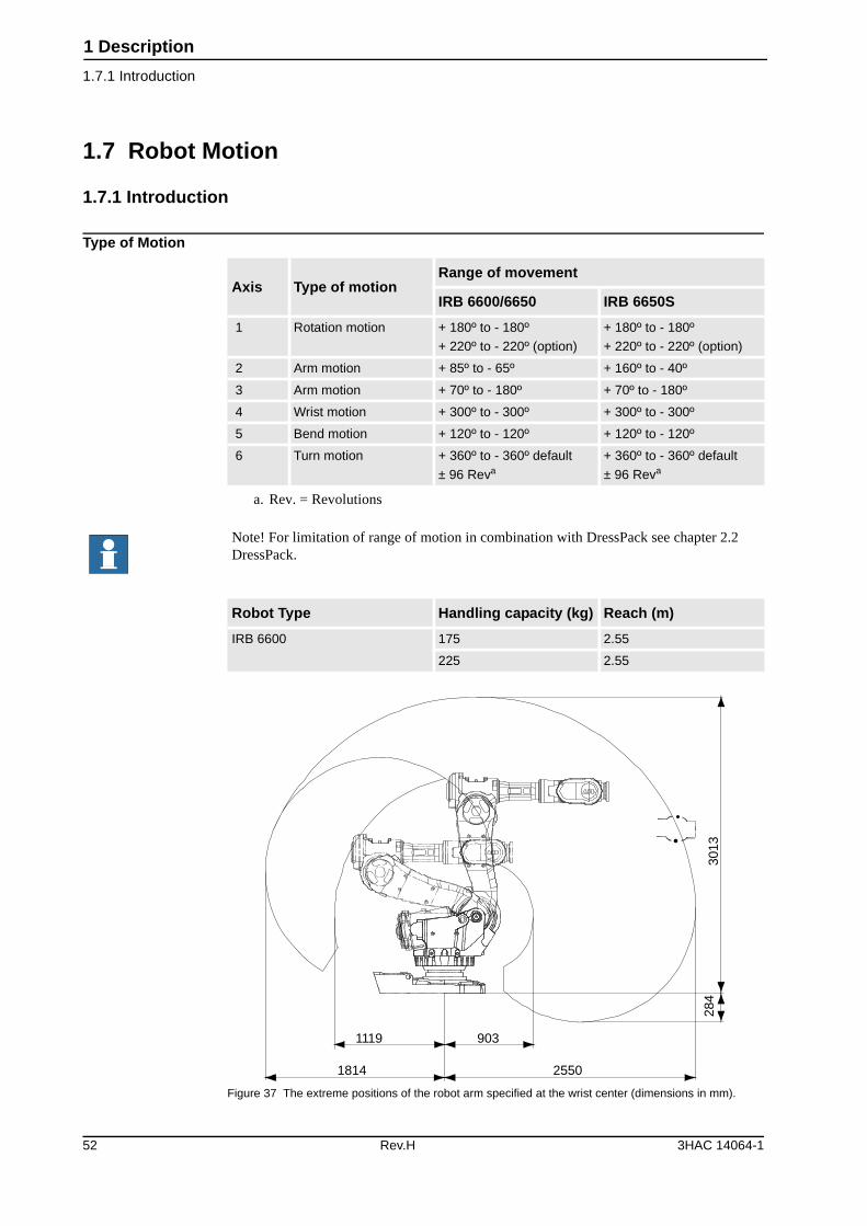
1.7 Robot Motion
1.7.1 Introduction
Type of Motion
Figure 37 The extreme positions of the robot arm specified at the wrist center (dimensions in mm).
Axis Type of motionRange of movement
IRB 6600/6650 IRB 6650S
1 Rotation motion + 180º to - 180º
+ 220º to - 220º (option)
+ 180º to - 180º
+ 220º to - 220º (option)
2 Arm motion + 85º to - 65º + 160º to - 40º
3 Arm motion + 70º to - 180º + 70º to - 180º
4 Wrist motion + 300º to - 300º + 300º to - 300º
5 Bend motion + 120º to - 120º + 120º to - 120º
6 Turn motion + 360º to - 360º default
± 96 Reva
a. Rev. = Revolutions
+ 360º to - 360º default
± 96 Reva
Note! For limitation of range of motion in combination with DressPack see chapter 2.2 DressPack.
Robot Type Handling capacity (kg) Reach (m)
IRB 6600 175 2.55
225 2.55
1814 2550
9031119
284
3013
52 Rev.H 3HAC 14064-1
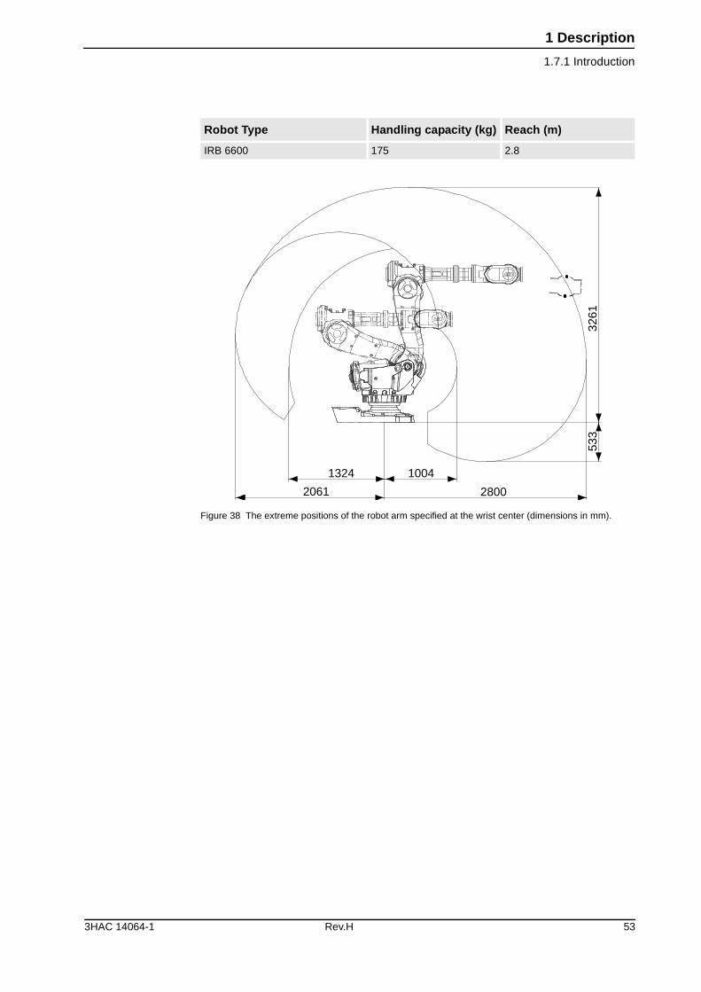
1 Description
1.7.1 Introduction
Figure 38 The extreme positions of the robot arm specified at the wrist center (dimensions in mm).
Robot Type Handling capacity (kg) Reach (m)
IRB 6600 175 2.8
1324 1004
28002061
533
3261
3HAC 14064-1 Rev.H 53
1 Description
1.7.1 Introduction
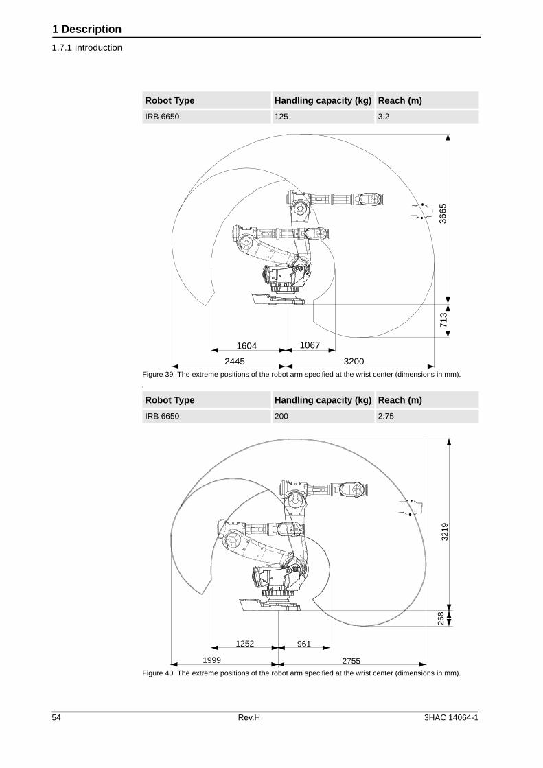
Figure 39 The extreme positions of the robot arm specified at the wrist center (dimensions in mm).
I
Figure 40 The extreme positions of the robot arm specified at the wrist center (dimensions in mm).
Robot Type Handling capacity (kg) Reach (m)
IRB 6650 125 3.2
Robot Type Handling capacity (kg) Reach (m)
IRB 6650 200 2.75
1604 1067
32002445
713
3665
1252 961
27551999
268
3219
54 Rev.H 3HAC 14064-1
1 Description
1.7.1 Introduction
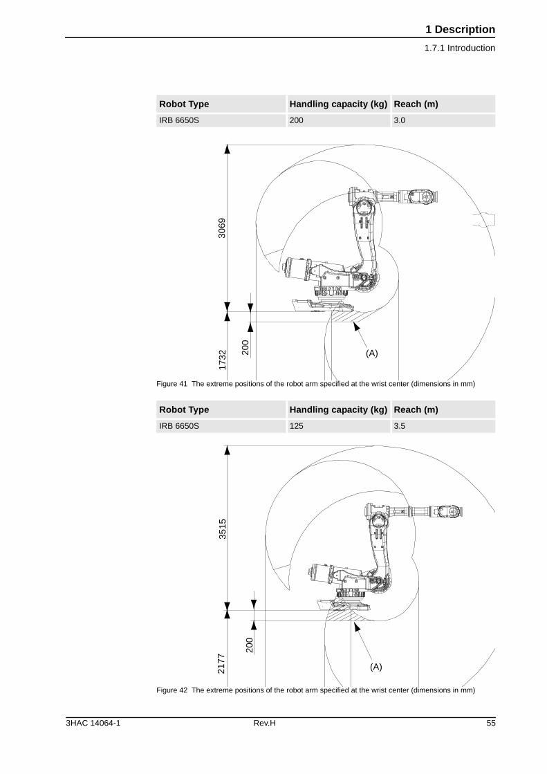
Figure 41 The extreme positions of the robot arm specified at the wrist center (dimensions in mm)
Figure 42 The extreme positions of the robot arm specified at the wrist center (dimensions in mm)
Robot Type Handling capacity (kg) Reach (m)
IRB 6650S 200 3.0
Robot Type Handling capacity (kg) Reach (m)
IRB 6650S 125 3.5
1732
3069
(A)200
3515
2177
(A)
200
3HAC 14064-1 Rev.H 55
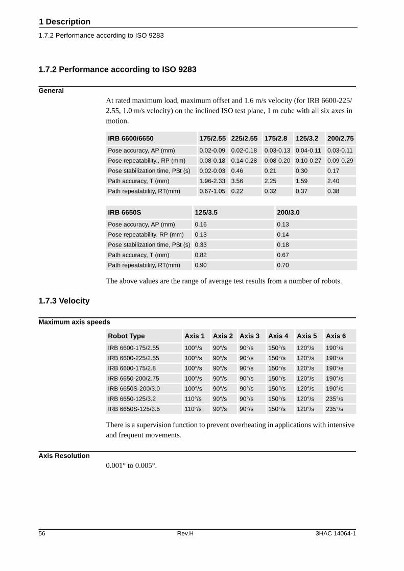
1 Description
1.7.2 Performance according to ISO 9283
1.7.2 Performance according to ISO 9283
GeneralAt rated maximum load, maximum offset and 1.6 m/s velocity (for IRB 6600-225/2.55, 1.0 m/s velocity) on the inclined ISO test plane, 1 m cube with all six axes in motion.
The above values are the range of average test results from a number of robots.
1.7.3 Velocity
Maximum axis speeds
There is a supervision function to prevent overheating in applications with intensive and frequent movements.
Axis Resolution0.001° to 0.005°.
IRB 6600/6650 175/2.55 225/2.55 175/2.8 125/3.2 200/2.75
Pose accuracy, AP (mm) 0.02-0.09 0.02-0.18 0.03-0.13 0.04-0.11 0.03-0.11
Pose repeatability., RP (mm) 0.08-0.18 0.14-0.28 0.08-0.20 0.10-0.27 0.09-0.29
Pose stabilization time, PSt (s) 0.02-0.03 0.46 0.21 0.30 0.17
Path accuracy, T (mm) 1.96-2.33 3.56 2.25 1.59 2.40
Path repeatability, RT(mm) 0.67-1.05 0.22 0.32 0.37 0.38
IRB 6650S 125/3.5 200/3.0
Pose accuracy, AP (mm) 0.16 0.13
Pose repeatability, RP (mm) 0.13 0.14
Pose stabilization time, PSt (s) 0.33 0.18
Path accuracy, T (mm) 0.82 0.67
Path repeatability, RT(mm) 0.90 0.70
Robot Type Axis 1 Axis 2 Axis 3 Axis 4 Axis 5 Axis 6
IRB 6600-175/2.55 100°/s 90°/s 90°/s 150°/s 120°/s 190°/s
IRB 6600-225/2.55 100°/s 90°/s 90°/s 150°/s 120°/s 190°/s
IRB 6600-175/2.8 100°/s 90°/s 90°/s 150°/s 120°/s 190°/s
IRB 6650-200/2.75 100°/s 90°/s 90°/s 150°/s 120°/s 190°/s
IRB 6650S-200/3.0 100°/s 90°/s 90°/s 150°/s 120°/s 190°/s
IRB 6650-125/3.2 110°/s 90°/s 90°/s 150°/s 120°/s 235°/s
IRB 6650S-125/3.5 110°/s 90°/s 90°/s 150°/s 120°/s 235°/s
56 Rev.H 3HAC 14064-1
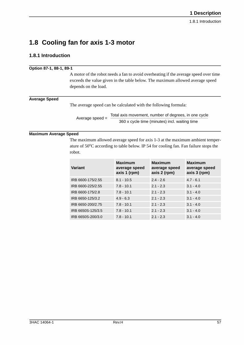
1 Description
1.8.1 Introduction
1.8 Cooling fan for axis 1-3 motor
1.8.1 Introduction
Option 87-1, 88-1, 89-1A motor of the robot needs a fan to avoid overheating if the average speed over time exceeds the value given in the table below. The maximum allowed average speed depends on the load.
Average SpeedThe average speed can be calculated with the following formula:
Maximum Average SpeedThe maximum allowed average speed for axis 1-3 at the maximum ambient temper-ature of 50oC according to table below. IP 54 for cooling fan. Fan failure stops the robot.
Average speed = Total axis movement, number of degrees, in one cycle
360 x cycle time (minutes) incl. waiting time
VariantMaximum average speed axis 1 (rpm)
Maximum average speed axis 2 (rpm)
Maximum average speed axis 3 (rpm)
IRB 6600-175/2.55 8.1 - 10.5 2.4 - 2.6 4.7 - 6.1
IRB 6600-225/2.55 7.8 - 10.1 2.1 - 2.3 3.1 - 4.0
IRB 6600-175/2.8 7.8 - 10.1 2.1 - 2.3 3.1 - 4.0
IRB 6650-125/3.2 4.9 - 6.3 2.1 - 2.3 3.1 - 4.0
IRB 6650-200/2.75 7.8 - 10.1 2.1 - 2.3 3.1 - 4.0
IRB 6650S-125/3.5 7.8 - 10.1 2.1 - 2.3 3.1 - 4.0
IRB 6650S-200/3.0 7.8 - 10.1 2.1 - 2.3 3.1 - 4.0
3HAC 14064-1 Rev.H 57
1 Description
1.9.1 Introduction
1.9 Servo Gun (option)
1.9.1 Introduction
GeneralThe robot can be supplied with hardware and software for:
• Stationary Gun
• Robot Gun
• Stationary and Robot Gun
• Twin Stationary Guns
• Stationary Gun and Track Motion
• Robot Gun and Track Motion
• Track Motion
For configuration and specification of hardware and software respectively, see each section below.
58 Rev.H 3HAC 14064-1
1 Description
1.9.2 Stationary Gun (SG)
1.9.2 Stationary Gun (SG)
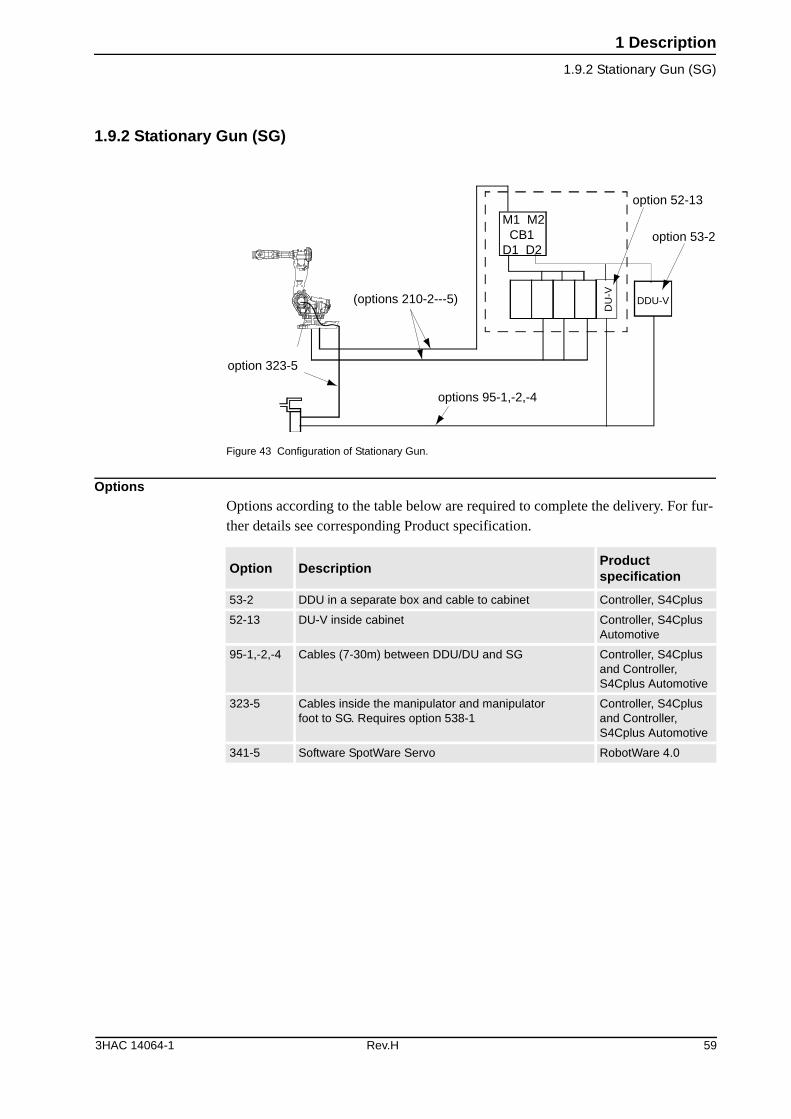
Figure 43 Configuration of Stationary Gun.
OptionsOptions according to the table below are required to complete the delivery. For fur-ther details see corresponding Product specification.
option 323-5
(options 210-2---5)
options 95-1,-2,-4
M1 M2 CB1D1 D2
option 52-13
option 53-2
DU
-V
DDU-V
Option DescriptionProduct specification
53-2 DDU in a separate box and cable to cabinet Controller, S4Cplus
52-13 DU-V inside cabinet Controller, S4Cplus Automotive
95-1,-2,-4 Cables (7-30m) between DDU/DU and SG Controller, S4Cplus and Controller, S4Cplus Automotive
323-5 Cables inside the manipulator and manipulator foot to SG. Requires option 538-1
Controller, S4Cplus and Controller, S4Cplus Automotive
341-5 Software SpotWare Servo RobotWare 4.0
3HAC 14064-1 Rev.H 59
1 Description
1.9.3 Robot Gun (RG)
1.9.3 Robot Gun (RG)
Figure 44 Configuration of Robot Gun.
OptionsOptions according to table below are required to complete the delivery. For further details see corresponding Product specification.
option 323-1
option 450-1,-2,-4
(options 210-2---5)
option 52-13
option 53-2
DDU-V
DU
-V
M1 M2 CB1D1 D2
Option DescriptionProduct specification
53-2 DDU in a separate box and cable to cabinet Controller, S4Cplus
52-13 DU-V inside cabinet Controller, S4Cplus Automotive
450-1,-2, -3a, -4
a. 450-3 not available for S4Cplus
Extended cables (7-30m) between DDU/DU and RG
Controller, S4Cplus and Controller, S4Cplus Automotive
323-1 Cabling inside the manipulator.
Requires option 455-1 and 476-1
Controller, S4Cplus and Controller, S4Cplus Automotive
341-5 Software SpotWare Servo RobotWare 4.0
60 Rev.H 3HAC 14064-1
1 Description
1.9.4 Stationary and Robot Gun (SG + RG)
1.9.4 Stationary and Robot Gun (SG + RG)
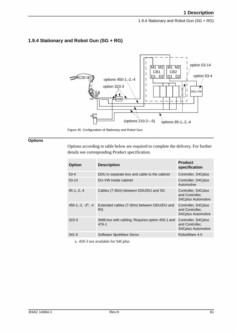
Figure 45 Configuration of Stationary and Robot Gun.
OptionsOptions according to table below are required to complete the delivery. For further details see corresponding Product specification.
option 323-3
(options 210-2---5)
options 450-1,-2,-4
SMB
option 53-14
DDU-VW
DU
-VW
options 95-1,-2,-4
M1 M2 CB1D1 D2
M1 M2 CB2D1 D2 option 53-4
Option DescriptionProduct specification
53-4 DDU in separate box and cable to the cabinet Controller, S4Cplus
53-14 DU-VW inside cabinet Controller, S4Cplus Automotive
95-1,-2,-4 Cables (7-30m) between DDU/DU and SG Controller, S4Cplus and Controller, S4Cplus Automotive
450-1,-2, -3a, -4
a. 450-3 not available for S4Cplus
Extended cables (7-30m) between DDU/DU and RG
Controller, S4Cplus and Controller, S4Cplus Automotive
323-3 SMB box with cabling. Requires option 455-1 and 476-1
Controller, S4Cplus and Controller, S4Cplus Automotive
341-5 Software SpotWare Servo RobotWare 4.0
3HAC 14064-1 Rev.H 61
1 Description
1.9.5 Twin Stationary Guns (SG + SG)
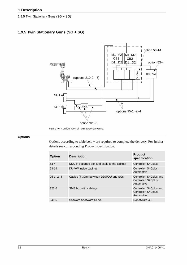
1.9.5 Twin Stationary Guns (SG + SG)
Figure 46 Configuration of Twin Stationary Guns.
OptionsOptions according to table below are required to complete the delivery. For further details see corresponding Product specification.
(options 210-2---5)
SG1
SG2 SMB
option 323-6
options 95-1,-2,-4
option 53-14
option 53-4
DDU-VW
DU
-VW
M1 M2 CB1D1 D2
M1 M2 CB2D1 D2
Option DescriptionProduct specification
53-4 DDU in separate box and cable to the cabinet Controller, S4Cplus
53-14 DU-VW inside cabinet Controller, S4Cplus Automotive
95-1,-2,-4 Cables (7-30m) between DDU/DU and SGs Controller, S4Cplus and Controller, S4Cplus Automotive
323-6 SMB box with cablings Controller, S4Cplus and Controller, S4Cplus Automotive
341-5 Software SpotWare Servo RobotWare 4.0
62 Rev.H 3HAC 14064-1
1 Description
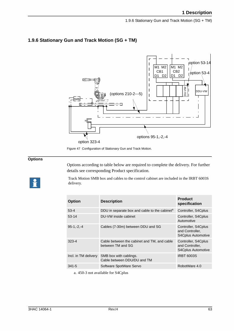
1.9.6 Stationary Gun and Track Motion (SG + TM)
1.9.6 Stationary Gun and Track Motion (SG + TM)
Figure 47 Configuration of Stationary Gun and Track Motion.
OptionsOptions according to table below are required to complete the delivery. For further details see corresponding Product specification.
(options 210-2---5)SMB
option 323-4options 95-1,-2,-4
option 53-14
option 53-4
DDU-VW
DU
-VW
M1 M2 CB1D1 D2
M1 M2 CB2D1 D2
Track Motion SMB box and cables to the control cabinet are included in the IRBT 6003S delivery.
Option DescriptionProduct specification
53-4 DDU in separate box and cable to the cabineta
a. 450-3 not available for S4Cplus
Controller, S4Cplus
53-14 DU-VW inside cabinet Controller, S4Cplus Automotive
95-1,-2,-4 Cables (7-30m) between DDU and SG Controller, S4Cplus and Controller, S4Cplus Automotive
323-4 Cable between the cabinet and TM, and cable between TM and SG
Controller, S4Cplus and Controller, S4Cplus Automotive
Incl. in TM delivery SMB box with cablings. Cable between DDU/DU and TM
IRBT 6003S
341-5 Software SpotWare Servo RobotWare 4.0
3HAC 14064-1 Rev.H 63
1 Description
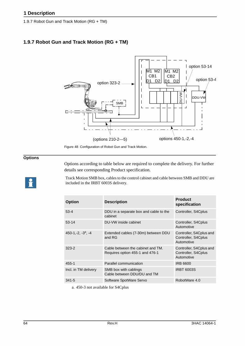
1.9.7 Robot Gun and Track Motion (RG + TM)
1.9.7 Robot Gun and Track Motion (RG + TM)
Figure 48 Configuration of Robot Gun and Track Motion.
OptionsOptions according to table below are required to complete the delivery. For further details see corresponding Product specification.
(options 210-2---5)
SMB
option 323-2
options 450-1,-2,-4
option 53-14
option 53-4
DDU-VW
DU
-VW
M1 M2 CB1D1 D2
M1 M2 CB2D1 D2
Track Motion SMB box, cables to the control cabinet and cable between SMB and DDU are included in the IRBT 6003S delivery.
Option DescriptionProduct specification
53-4 DDU in a separate box and cable to the cabinet
Controller, S4Cplus
53-14 DU-VW inside cabinet Controller, S4Cplus Automotive
450-1,-2, -3a, -4
a. 450-3 not available for S4Cplus
Extended cables (7-30m) between DDU and RG
Controller, S4Cplus and Controller, S4Cplus Automotive
323-2 Cable between the cabinet and TM. Requires option 455-1 and 476-1
Controller, S4Cplus and Controller, S4Cplus Automotive
455-1 Parallel communication IRB 6600
Incl. in TM delivery SMB box with cablingsCable between DDU/DU and TM
IRBT 6003S
341-5 Software SpotWare Servo RobotWare 4.0
64 Rev.H 3HAC 14064-1
1 Description
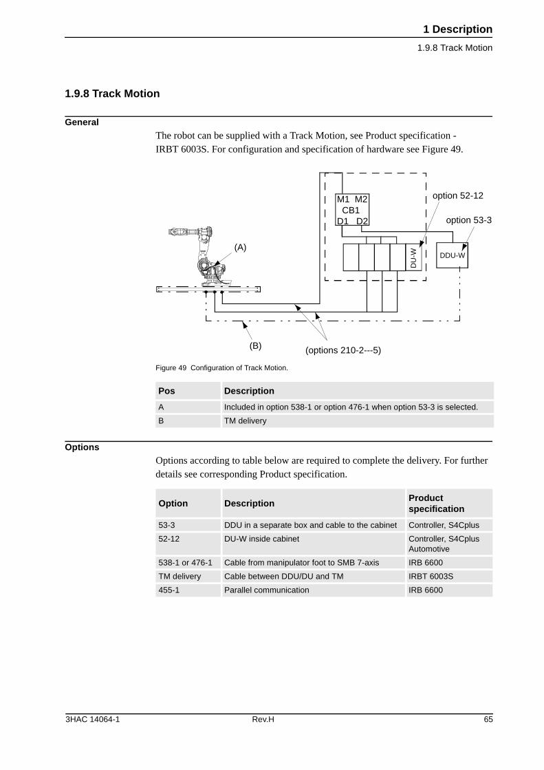
1.9.8 Track Motion
1.9.8 Track Motion
GeneralThe robot can be supplied with a Track Motion, see Product specification - IRBT 6003S. For configuration and specification of hardware see Figure 49.
Figure 49 Configuration of Track Motion.
OptionsOptions according to table below are required to complete the delivery. For further details see corresponding Product specification.
Pos Description
A Included in option 538-1 or option 476-1 when option 53-3 is selected.
B TM delivery
(options 210-2---5)(B)
(A)
option 52-12
option 53-3
DDU-W
DU
-W
M1 M2 CB1D1 D2
Option DescriptionProduct specification
53-3 DDU in a separate box and cable to the cabinet Controller, S4Cplus
52-12 DU-W inside cabinet Controller, S4Cplus Automotive
538-1 or 476-1 Cable from manipulator foot to SMB 7-axis IRB 6600
TM delivery Cable between DDU/DU and TM IRBT 6003S
455-1 Parallel communication IRB 6600
3HAC 14064-1 Rev.H 65

1 Description
1.9.8 Track Motion
66 Rev.H 3HAC 14064-1
2 SpotPack and DressPack
2.1.1 General
2 SpotPack and DressPack
2.1 Introduction
2.1.1 General
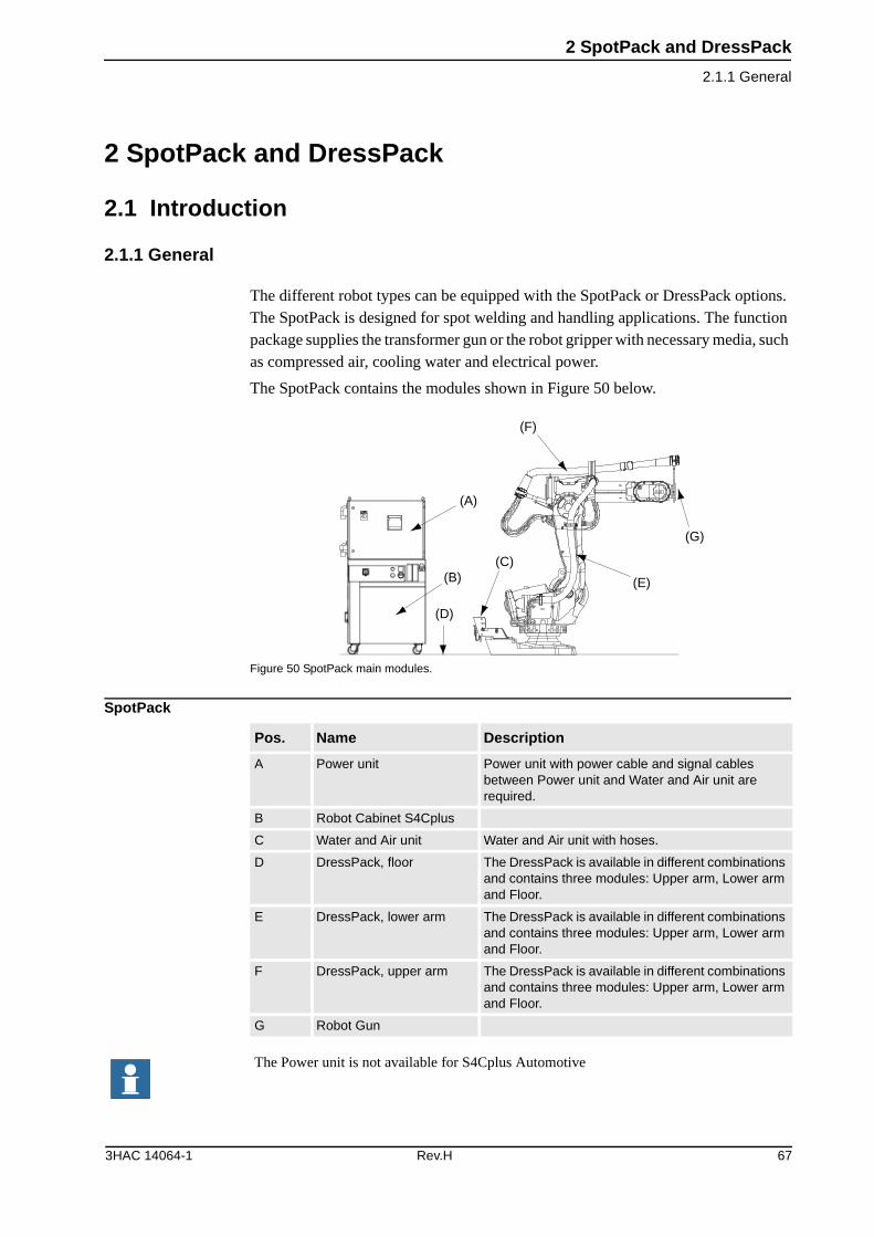
The different robot types can be equipped with the SpotPack or DressPack options. The SpotPack is designed for spot welding and handling applications. The function package supplies the transformer gun or the robot gripper with necessary media, such as compressed air, cooling water and electrical power.
The SpotPack contains the modules shown in Figure 50 below.
Figure 50 SpotPack main modules.
SpotPack
(A)
(B)
(D)
(C)
(E)
(F)
(G)
Pos. Name Description
A Power unit Power unit with power cable and signal cables between Power unit and Water and Air unit are required.
B Robot Cabinet S4Cplus
C Water and Air unit Water and Air unit with hoses.
D DressPack, floor The DressPack is available in different combinations and contains three modules: Upper arm, Lower arm and Floor.
E DressPack, lower arm The DressPack is available in different combinations and contains three modules: Upper arm, Lower arm and Floor.
F DressPack, upper arm The DressPack is available in different combinations and contains three modules: Upper arm, Lower arm and Floor.
G Robot Gun
The Power unit is not available for S4Cplus Automotive
3HAC 14064-1 Rev.H 67
2 SpotPack and DressPack
2.1.2 Chapter Structure
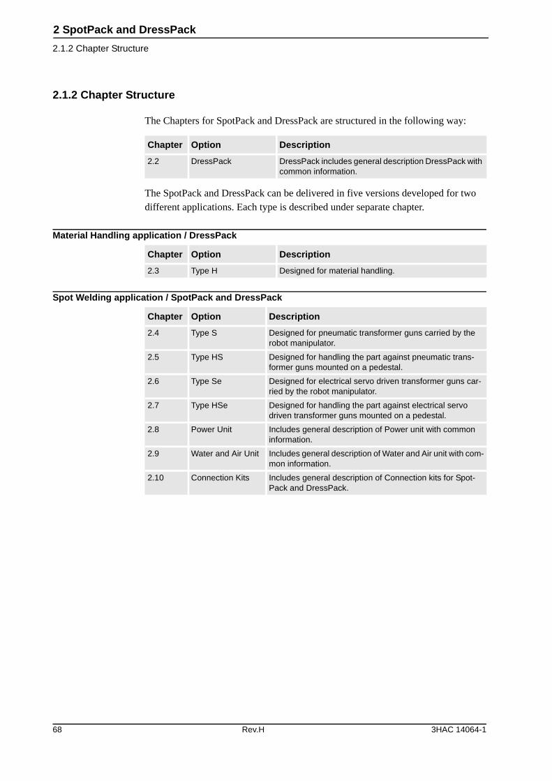
2.1.2 Chapter Structure
The Chapters for SpotPack and DressPack are structured in the following way:
The SpotPack and DressPack can be delivered in five versions developed for two different applications. Each type is described under separate chapter.
Material Handling application / DressPack
Spot Welding application / SpotPack and DressPack
Chapter Option Description
2.2 DressPack DressPack includes general description DressPack with common information.
Chapter Option Description
2.3 Type H Designed for material handling.
Chapter Option Description
2.4 Type S Designed for pneumatic transformer guns carried by the robot manipulator.
2.5 Type HS Designed for handling the part against pneumatic trans-former guns mounted on a pedestal.
2.6 Type Se Designed for electrical servo driven transformer guns car-ried by the robot manipulator.
2.7 Type HSe Designed for handling the part against electrical servo driven transformer guns mounted on a pedestal.
2.8 Power Unit Includes general description of Power unit with common information.
2.9 Water and Air Unit Includes general description of Water and Air unit with com-mon information.
2.10 Connection Kits Includes general description of Connection kits for Spot-Pack and DressPack.
68 Rev.H 3HAC 14064-1
2 SpotPack and DressPack
2.2.1 Introduction
2.2 DressPack
2.2.1 Introduction
GeneralDress Pack includes options for Upper arm, Lower arm and Floor. These are described separated below but are designed as a complete package for various appli-cations. The DressPack for upper and lower arm contains signals, process media (water and/or air) and power feeding (for Spot Welding power) for customer use.
The DressPack for the floor contains customer signals.
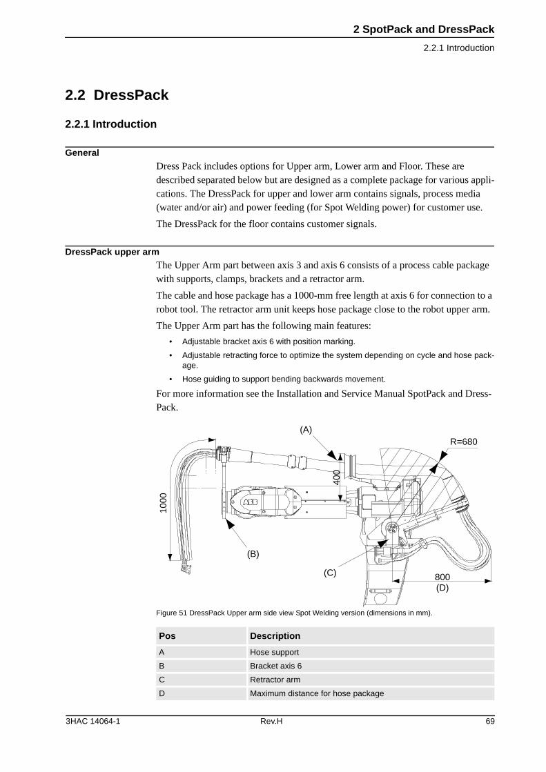
DressPack upper armThe Upper Arm part between axis 3 and axis 6 consists of a process cable package with supports, clamps, brackets and a retractor arm.
The cable and hose package has a 1000-mm free length at axis 6 for connection to a robot tool. The retractor arm unit keeps hose package close to the robot upper arm.
The Upper Arm part has the following main features:
• Adjustable bracket axis 6 with position marking.
• Adjustable retracting force to optimize the system depending on cycle and hose pack-age.
• Hose guiding to support bending backwards movement.
For more information see the Installation and Service Manual SpotPack and Dress-Pack.
Figure 51 DressPack Upper arm side view Spot Welding version (dimensions in mm).
Pos Description
A Hose support
B Bracket axis 6
C Retractor arm
D Maximum distance for hose package
1000
(A)
(B)
(C)
(D)800
R=680
400
3HAC 14064-1 Rev.H 69
2 SpotPack and DressPack
2.2.1 Introduction
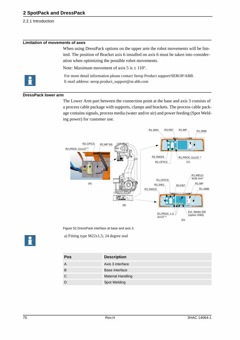
Limitation of movements of axesWhen using DressPack options on the upper arm the robot movements will be lim-ited. The position of Bracket axis 6 installed on axis 6 must be taken into consider-ation when optimizing the possible robot movements.
Note: Maximum movement of axis 5 is ± 110º.
DressPack lower armThe Lower Arm part between the connection point at the base and axis 3 consists of a process cable package with supports, clamps and brackets. The process cable pack-age contains signals, process media (water and/or air) and power feeding (Spot Weld-ing power) for customer use.
Figure 52 DressPack interface at base and axis 3.
For more detail information please contact Serop Product support/SEROP/ABB.
E-mail address: [email protected]
R2.PROC 11x1/2” a)
R2.CP/CS R2.MP 5/6
(A)
R1.SW1 R3.FB7 R1.MP R1.SMB
R1.SW2/3
R1.CP/CS (C)
R1.PROC 11x1/2 a)
R1.SW2/3
R1.SW1
R1.CP/CS
R3.FB7
R1.WELD3x35 mm2
R1.MP
R1.SMB
Ext. Media SW(option 2065)
(D)
R1.PROC 1-33x1/2” a)
(B)
a) Fitting type M22x1,5; 24 degree seal
Pos Description
A Axis 3 interface
B Base interface
C Material Handling
D Spot Welding
70 Rev.H 3HAC 14064-1
2 SpotPack and DressPack
2.2.1 Introduction
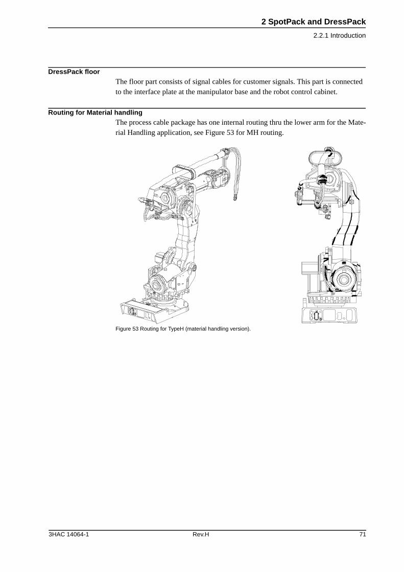
DressPack floorThe floor part consists of signal cables for customer signals. This part is connected to the interface plate at the manipulator base and the robot control cabinet.
Routing for Material handlingThe process cable package has one internal routing thru the lower arm for the Mate-rial Handling application, see Figure 53 for MH routing.
Figure 53 Routing for TypeH (material handling version).
3HAC 14064-1 Rev.H 71
2 SpotPack and DressPack
2.2.1 Introduction
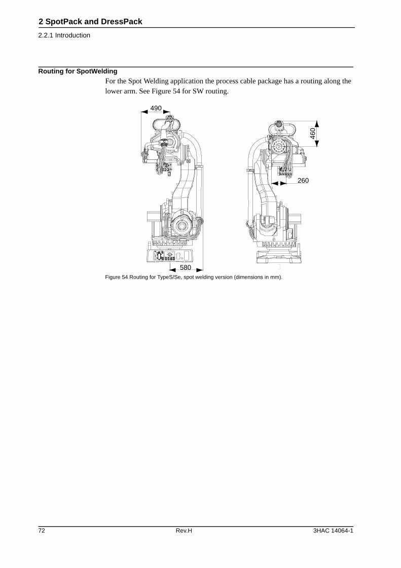
Routing for SpotWeldingFor the Spot Welding application the process cable package has a routing along the lower arm. See Figure 54 for SW routing.
Figure 54 Routing for TypeS/Se, spot welding version (dimensions in mm).
490
580
460
260
72 Rev.H 3HAC 14064-1
2 SpotPack and DressPack
2.3.1 Introduction
2.3 Type H
2.3.1 Introduction
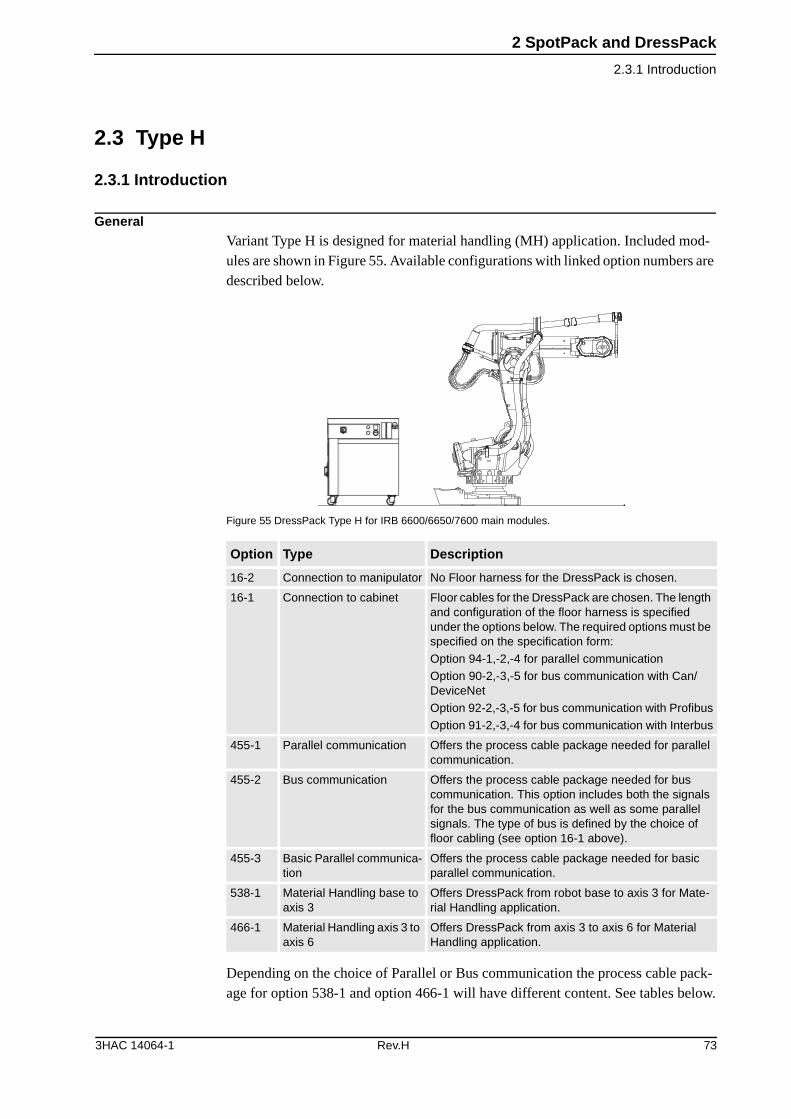
GeneralVariant Type H is designed for material handling (MH) application. Included mod-ules are shown in Figure 55. Available configurations with linked option numbers are described below.
Figure 55 DressPack Type H for IRB 6600/6650/7600 main modules.
Depending on the choice of Parallel or Bus communication the process cable pack-age for option 538-1 and option 466-1 will have different content. See tables below.
Option Type Description
16-2 Connection to manipulator No Floor harness for the DressPack is chosen.
16-1 Connection to cabinet Floor cables for the DressPack are chosen. The length and configuration of the floor harness is specified under the options below. The required options must be specified on the specification form:
Option 94-1,-2,-4 for parallel communication
Option 90-2,-3,-5 for bus communication with Can/DeviceNet
Option 92-2,-3,-5 for bus communication with Profibus
Option 91-2,-3,-4 for bus communication with Interbus
455-1 Parallel communication Offers the process cable package needed for parallel communication.
455-2 Bus communication Offers the process cable package needed for bus communication. This option includes both the signals for the bus communication as well as some parallel signals. The type of bus is defined by the choice of floor cabling (see option 16-1 above).
455-3 Basic Parallel communica-tion
Offers the process cable package needed for basic parallel communication.
538-1 Material Handling base to axis 3
Offers DressPack from robot base to axis 3 for Mate-rial Handling application.
466-1 Material Handling axis 3 to axis 6
Offers DressPack from axis 3 to axis 6 for Material Handling application.
3HAC 14064-1 Rev.H 73
2 SpotPack and DressPack
2.3.1 Introduction
Dress Pack Type H. Basic Parallel communication• Option 16-2 or Option 16-1 with Connection to cabinet (option 94-1, -2, -4 to specify
cable length)
• Option 455-3 Basic Parallel communication
• Option 538-1 Material Handling base to axis 3
This configuration could not be combined with Option 466-1 Material Handling axis 3 to axis 6.
TypeAt terminals in cabinet
At Connection pointa
a. Interface at manipulator base or axis 3 (option 538-1)
Cable part area
Allowed capacity
Customer Power (CP)Utility Power
Protective Ground
2
1
2
1
0,96 mm2
0,96mm2
250 VAC, 6 A rms
250 VAC
Customer Signals (CS)Signals twisted pair
Signals twisted pair and separate shielded
14 (7x2)
2 (1x2)
14 (7x2)
2 (1x2)
0,23mm2
0,23 mm2
50 VAC, 1 A rms
50 VAC, 1 A rms
MediaAir (PROC 1) 1 12,5 mm
inner diameter
Max. pressure 16 bar /230 PSI
74 Rev.H 3HAC 14064-1
2 SpotPack and DressPack
2.3.1 Introduction
DressPack Type H. Parallel communication• Option 16-2 or Option 16-1 with Connection to cabinet (option 94-1,-2,-4 to specify
cable length)
• Option 455-1 Parallel communication
• Option 538-1 Material Handling base to axis 3
• Option 466-1 Material Handling axis 3 to axis 6
TypeAt terminals in cabinet
At connection pointa
a. Interface at manipulator base or axis 3 (option 538-1) or axis 6 (option 466-1)
Cable part area
Allowed capacity
Customer Power (CP)Utility Power
Utility Power
Protective Ground
2+2
3
1
2+2
3
1
0,5 mm2
1,5 mm2
1,5 mm2
250 VAC, 5 A rms
250 VAC, 12 A rms
250 VAC
Customer Signals (CS)Signals twisted pair
Signals twisted pair and
separate shielded
16 (8x2)
8 (4x2)
16 (8x2)
8 (4x2)
0,23 mm2
0,23 mm2
50 V DC, 1 A rms
50 V DC, 1 A rms
MediaAir (PROC 1) 1 12,5 mm
inner diameter
Max. pressure 16 bar/ 230 PSI
3HAC 14064-1 Rev.H 75
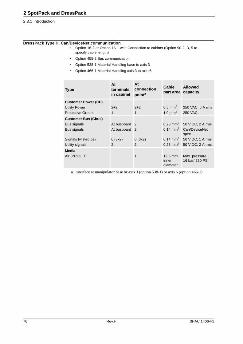
2 SpotPack and DressPack
2.3.1 Introduction
DressPack Type H. Can/DeviceNet communication• Option 16-2 or Option 16-1 with Connection to cabinet (Option 90-2,-3,-5 to
specify cable length)
• Option 455-2 Bus communication
• Option 538-1 Material Handling base to axis 3
• Option 466-1 Material Handling axis 3 to axis 6
TypeAt terminals in cabinet
At connection pointa
a. Interface at manipulator base or axis 3 (option 538-1) or axis 6 (option 466-1)
Cable part area
Allowed capacity
Customer Power (CP)Utility Power
Protective Ground
2+2
1
2+2
1
0,5 mm2
1,0 mm2
250 VAC, 5 A rms
250 VAC
Customer Bus (Cbus)Bus signals
Bus signals
Signals twisted pair
Utility signals
At busboard
At busboard
6 (3x2)
2
2
2
6 (3x2)
2
0,23 mm2
0,14 mm2
0,14 mm2
0,23 mm2
50 V DC, 2 A rms
Can/DeviceNet spec
50 V DC, 1 A rms
50 V DC, 2 A rms
MediaAir (PROC 1) 1 12,5 mm
inner diameter
Max. pressure 16 bar/ 230 PSI
76 Rev.H 3HAC 14064-1
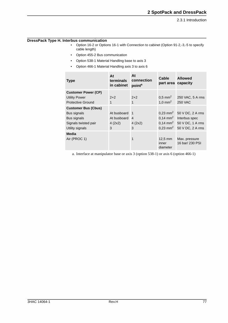
2 SpotPack and DressPack
2.3.1 Introduction
DressPack Type H. Interbus communication• Option 16-2 or Options 16-1 with Connection to cabinet (Option 91-2,-3,-5 to specify
cable length)
• Option 455-2 Bus communication
• Option 538-1 Material Handling base to axis 3
• Option 466-1 Material Handling axis 3 to axis 6
TypeAt terminals in cabinet
At connection pointa
a. Interface at manipulator base or axis 3 (option 538-1) or axis 6 (option 466-1)
Cable part area
Allowed capacity
Customer Power (CP)Utility Power
Protective Ground
2+2
1
2+2
1
0,5 mm2
1,0 mm2
250 VAC, 5 A rms
250 VAC
Customer Bus (Cbus)Bus signals
Bus signals
Signals twisted pair
Utility signals
At busboard
At busboard
4 (2x2)
3
1
4
4 (2x2)
3
0,23 mm2
0,14 mm2
0,14 mm2
0,23 mm2
50 V DC, 2 A rms
Interbus spec
50 V DC, 1 A rms
50 V DC, 2 A rms
MediaAir (PROC 1) 1 12,5 mm
inner diameter
Max. pressure 16 bar/ 230 PSI
3HAC 14064-1 Rev.H 77
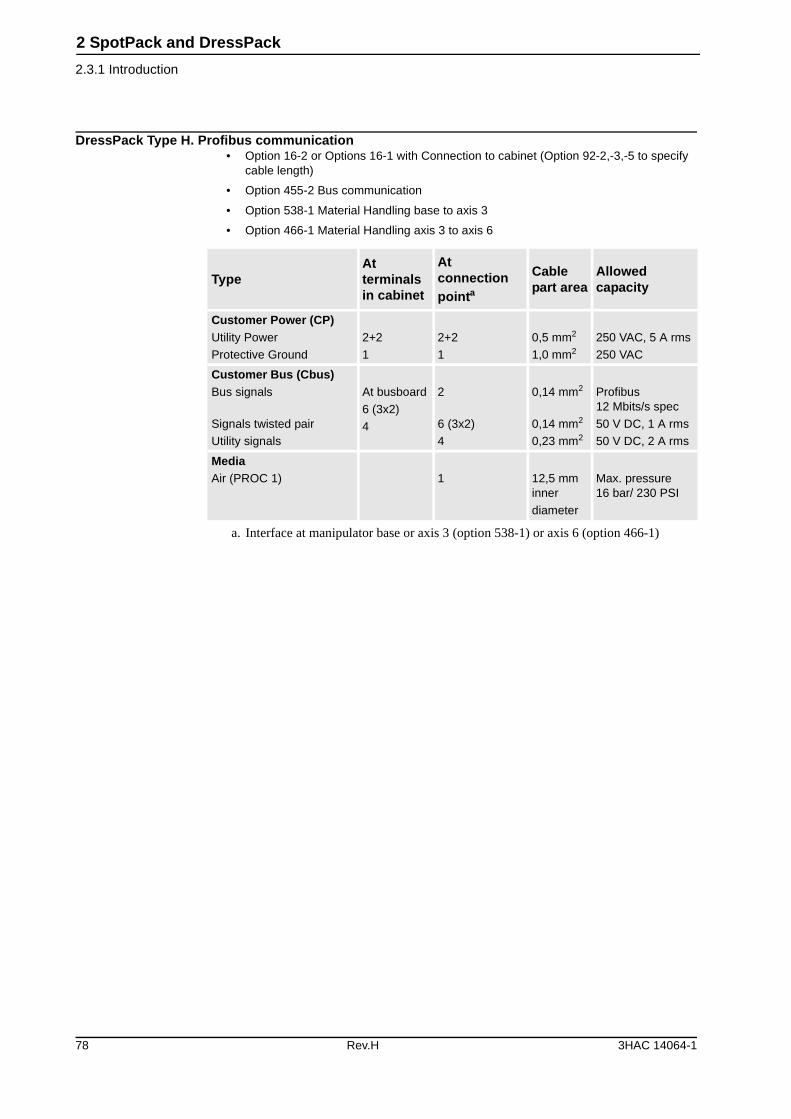
2 SpotPack and DressPack
2.3.1 Introduction
DressPack Type H. Profibus communication• Option 16-2 or Options 16-1 with Connection to cabinet (Option 92-2,-3,-5 to specify
cable length)
• Option 455-2 Bus communication
• Option 538-1 Material Handling base to axis 3
• Option 466-1 Material Handling axis 3 to axis 6
TypeAt terminals in cabinet
At connection pointa
a. Interface at manipulator base or axis 3 (option 538-1) or axis 6 (option 466-1)
Cable part area
Allowed capacity
Customer Power (CP)Utility Power
Protective Ground
2+2
1
2+2
1
0,5 mm2
1,0 mm2
250 VAC, 5 A rms
250 VAC
Customer Bus (Cbus)Bus signals
Signals twisted pair
Utility signals
At busboard
6 (3x2)
4
2
6 (3x2)
4
0,14 mm2
0,14 mm2
0,23 mm2
Profibus12 Mbits/s spec
50 V DC, 1 A rms
50 V DC, 2 A rms
MediaAir (PROC 1) 1 12,5 mm
inner
diameter
Max. pressure 16 bar/ 230 PSI
78 Rev.H 3HAC 14064-1
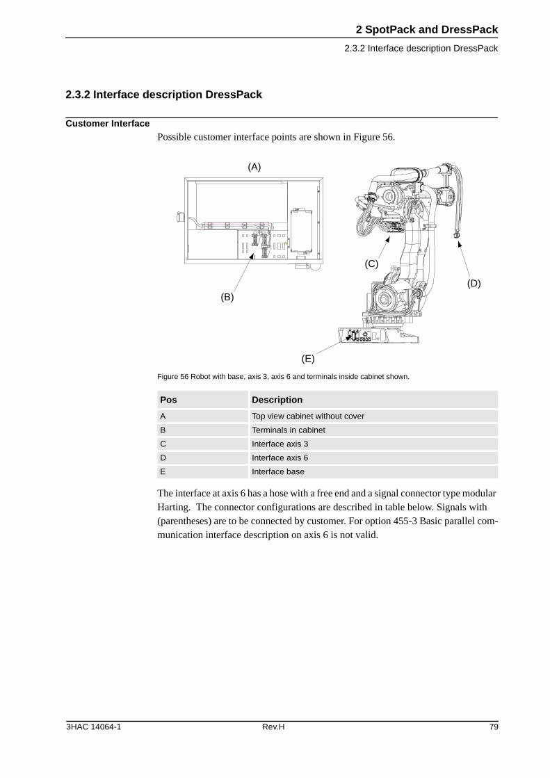
2 SpotPack and DressPack
2.3.2 Interface description DressPack
2.3.2 Interface description DressPack
Customer InterfacePossible customer interface points are shown in Figure 56.
Figure 56 Robot with base, axis 3, axis 6 and terminals inside cabinet shown.
The interface at axis 6 has a hose with a free end and a signal connector type modular Harting. The connector configurations are described in table below. Signals with (parentheses) are to be connected by customer. For option 455-3 Basic parallel com-munication interface description on axis 6 is not valid.
Pos Description
A Top view cabinet without cover
B Terminals in cabinet
C Interface axis 3
D Interface axis 6
E Interface base
XT6 XT5.1
(A)
(B)
(C)
(D)
(E)
3HAC 14064-1 Rev.H 79

2 SpotPack and DressPack
2.3.2 Interface description DressPack
Figure 57 Modulharting axis 6.
Connection
Customer power signals
Pos Description
A Module version
EE
HD
DDEE
(A)
Name
TerminalPin No.
Pin No.
Communication types
Cabinet Base and Axis 3
Axis 6 Basic Parallel
Parallel Can Device-Net
Inter-bus
Profi-bus
Hartingmodule type (see page 82)
EE+HD EE+HD EE+DD EE+DD EE+DD
Name
TerminalPin No.
Pin No.
Communication types
Cabinet Base and Axis 3
Axis 6 Basic Parallel
Parallel Can/DeviceNet
Inter-bus
Profi-bus
(+24 V) XT 6:1/1 D1 B4 Yes Yes Yes Yes Yes
(0 V) XT 6:1/2 D6 B5 Yes Yes Yes Yes Yes
(+24 V) XT 6:1/3 D3 B6 - Yes Yes Yes Yes
(0 V) XT 6:1/4 D4 B7 - Yes Yes Yes Yes
Ground (in housing)
GND GND GND Yes Yes Yes Yes Yes
(Spare) XT 6:1/5 D5 B1 - Yes - - -
(Spare) XT 6:1/6 D2 B2 - Yes - - -
(Spare) XT 6:1/7 D7 B3 - Yes - - -
80 Rev.H 3HAC 14064-1

2 SpotPack and DressPack
2.3.2 Interface description DressPack
Customer Signals
Name
TerminalPin No.
Pin No.
Communication types
Cabinet Base and Axis 3
Axis 6 Basic Parallel
Parallel Can/ DeviceNet
Inter-bus
Profi-bus
(Spare) XT 5:1/1 B1 A18 Yes Yes - - -
(Spare) XT 5:1/2 B2 A19 Yes Yes - - -
(Spare) Sep. screened
XT 5:2/17 B3 A20 Yes Yes - - -
(Spare) Sep. screened
XT 5:2/18 B4 A21 Yes Yes - - -
(Spare) Sep. screened
XT 5:2/21 B5 A22 Yes* Yes - - -
(Spare)Sep. screened
XT 5:2/22 B6 A23 Yes* Yes - - -
(Spare) Sep. screened
XT 5:2/13 B7 A24 Yes* Yes - - -
(Spare) Sep. screened
XT 5:2/14 B8 A25 Yes* Yes - - -
(Spare) Sep. screened
XT 5:2/15 B9 A16 Yes* Yes - - -
(Spare) Sep. screened
XT 5:2/16 B10 A17 Yes* Yes - - -
(Spare) XT 5:1/3 B11 A1 Yes* Yes - - -
(Spare) XT 5:1/4 B12 A2 Yes* Yes - - -
(Spare) XT 5:1/5 B13 A3 Yes* Yes - - -
(Spare) XT 5:1/6 B14 A4 Yes* Yes - - -
(Spare) XT 5:1/7 B15 A5 Yes* Yes - - -
(Spare) XT 5:1/8 B16 A6 Yes* Yes - - -
(Spare) XT 5:1/9 B18 A7 - Yes - - -
(Spare) XT 5:1/10 B19 A8 - Yes - - -
(Spare) XT 5:1/11 B20 A9 - Yes - - -
(Spare) XT 5:1/12 B21 A10 - Yes - - -
(Spare) XT 5:2/19 C1 A11 - Yes - - -
(Spare) XT 5:2/20 C2 A12 - Yes - - -
(Spare) XT 5:2/23 C3 A13 - Yes - - -
(Spare) XT 5:2/24 C4 A14 - Yes - - -
Not in use - - - - - - - -
3HAC 14064-1 Rev.H 81
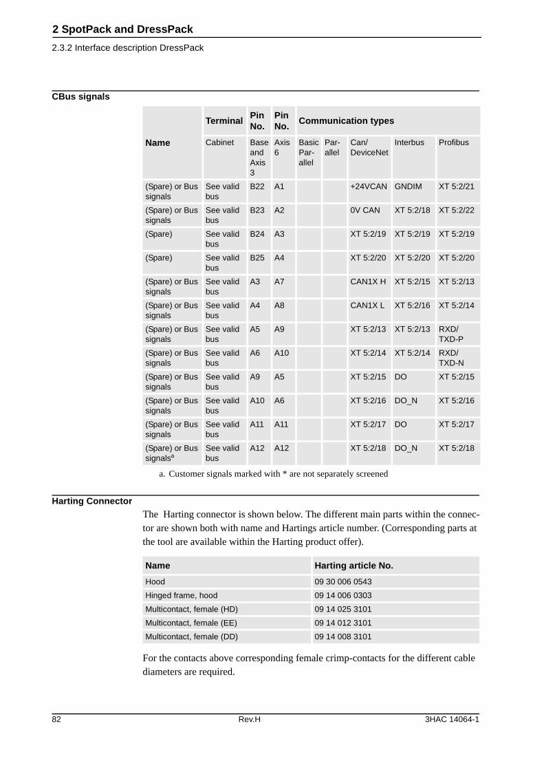
2 SpotPack and DressPack
2.3.2 Interface description DressPack
CBus signals
Harting ConnectorThe Harting connector is shown below. The different main parts within the connec-tor are shown both with name and Hartings article number. (Corresponding parts at the tool are available within the Harting product offer).
For the contacts above corresponding female crimp-contacts for the different cable diameters are required.
Name
TerminalPin No.
Pin No.
Communication types
Cabinet Base and Axis 3
Axis 6
Basic Par-allel
Par-allel
Can/ DeviceNet
Interbus Profibus
(Spare) or Bus signals
See valid bus
B22 A1 +24VCAN GNDIM XT 5:2/21
(Spare) or Bus signals
See valid bus
B23 A2 0V CAN XT 5:2/18 XT 5:2/22
(Spare) See valid bus
B24 A3 XT 5:2/19 XT 5:2/19 XT 5:2/19
(Spare) See valid bus
B25 A4 XT 5:2/20 XT 5:2/20 XT 5:2/20
(Spare) or Bus signals
See valid bus
A3 A7 CAN1X H XT 5:2/15 XT 5:2/13
(Spare) or Bus signals
See valid bus
A4 A8 CAN1X L XT 5:2/16 XT 5:2/14
(Spare) or Bus signals
See valid bus
A5 A9 XT 5:2/13 XT 5:2/13 RXD/TXD-P
(Spare) or Bus signals
See valid bus
A6 A10 XT 5:2/14 XT 5:2/14 RXD/TXD-N
(Spare) or Bus signals
See valid bus
A9 A5 XT 5:2/15 DO XT 5:2/15
(Spare) or Bus signals
See valid bus
A10 A6 XT 5:2/16 DO_N XT 5:2/16
(Spare) or Bus signals
See valid bus
A11 A11 XT 5:2/17 DO XT 5:2/17
(Spare) or Bus signalsa
a. Customer signals marked with * are not separately screened
See valid bus
A12 A12 XT 5:2/18 DO_N XT 5:2/18
Name Harting article No.
Hood 09 30 006 0543
Hinged frame, hood 09 14 006 0303
Multicontact, female (HD) 09 14 025 3101
Multicontact, female (EE) 09 14 012 3101
Multicontact, female (DD) 09 14 008 3101
82 Rev.H 3HAC 14064-1

2 SpotPack and DressPack
2.3.3 Summary Type H
2.3.3 Summary Type H
The following options are required to form a complete DressPack Type H:
Option Description
16-1 Connection to cabinet (Cable length and communication type to be stated)
455-1, 455-2, 455-3 Basic Parallel, Parallel or Bus communication (Communication type to be stated)
538-1 Material Handling base to axis 3 (DressPackage lower arm)
466-1 Material Handling axis 3 to axis 6 (DressPackage upper arm)
3HAC 14064-1 Rev.H 83
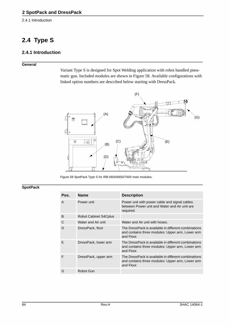
2 SpotPack and DressPack
2.4.1 Introduction
2.4 Type S
2.4.1 Introduction
GeneralVariant Type S is designed for Spot Welding application with robot handled pneu-matic gun. Included modules are shown in Figure 58. Available configurations with linked option numbers are described below starting with DressPack.
Figure 58 SpotPack Type S for IRB 6600/6650/7600 main modules.
SpotPack
(A)
(B)(C)
(D)
(F)
(E)
(G)
Pos. Name Description
A Power unit Power unit with power cable and signal cables between Power unit and Water and Air unit are required.
B Robot Cabinet S4Cplus
C Water and Air unit Water and Air unit with hoses.
D DressPack, floor The DressPack is available in different combinations and contains three modules: Upper arm, Lower arm and Floor.
E DressPack, lower arm The DressPack is available in different combinations and contains three modules: Upper arm, Lower arm and Floor.
F DressPack, upper arm The DressPack is available in different combinations and contains three modules: Upper arm, Lower arm and Floor.
G Robot Gun
84 Rev.H 3HAC 14064-1
2 SpotPack and DressPack
2.4.1 Introduction
Depending on the choice of Parallel or Bus communication the process cable pack-age for option 476-1 and option 475-1 will have different content. See the following tables.
Option Type Description
16-2 Connection to manipulator No Floor harness for the DressPack is chosen.
16-1 Connection to cabinet Floor cables for the DressPack are chosen. The length and configuration of the floor harness is spec-ified under the options below. The required options must be specified in the specification form:
Option 94-1,-2,-4 for parallel communication
Option 90-2,-3,-5 for bus communication with Can/DeviceNet
Option 92-2,-3,-5 for bus communication with Profi-bus
Option 91-2,-3,-5 for bus communication with Inter-bus
455-1 Parallel communication Offers the process cable package needed for parallel communication.
455-2 Bus communication Offers the process cable package needed for bus communication. This option includes both the sig-nals for the bus communication as well as some par-allel signals. The type of bus is defined by the choice of floor cabling (see option 16-1 above).
476-1 Spot Welding base to axis 3 Offers Dresspack from robot base to axis 3 for Spot Welding application.
475-1 Spot Welding axis 3 to axis 6
Offers DressPack from robot axis 3 to axis 6 for Spot Welding application.
3HAC 14064-1 Rev.H 85
2 SpotPack and DressPack
2.4.1 Introduction
DressPack Type S. Parallel communication• Option 16-2 or 16-1 with Connection to cabinet (option 94-1,-2,-4 for cable length)
• Option 455-1 Parallel communication
• Option 476-1 Spot Welding base to axis 3
• Option 475-1 Spot Welding axis 3 to axis 6
TypeAt terminals in cabinet
At connection pointa
a. Interface at manipulator base or axis 3 (option 476-1) or axis 6 (option 475-1)
Cable part area
Allowed capacity
Customer Power (CP)Utility Power
Utility Power
Protective Ground
2+2
3
1
2+2
3
1
0,5 mm2
1,5 mm2
1,5 mm2
250 VAC, 5 A rms
250 VAC, 12 A rms
250 VAC
Customer Signals (CS)Signals twisted pair
Signals twisted pair and separate shielded
16 (8x2)
8 (4x2)
16 (8x2)
8 (4x2)
0,23 mm2
0,23 mm2
50 V DC, 1 A rms
50 V DC, 1 A rms
MediaWater/Air (PROC 1-3) 3 12,5 mm
inner diameter
Max. air pressure 16 bar/ 230 PSI.
Max. water pres-sure 10 bar/ 145 PSI
Welding power (WELD)Lower arm
Lower arm, protective ground
Upper arm
Upper arm, protective ground
2
1
2
1
35 mm2
35 mm2
25 mm2
25 mm2
600 VAC, 150 A rms at 20oC (68F)
600 VAC, 135 A rms at 20oC (68F)
86 Rev.H 3HAC 14064-1
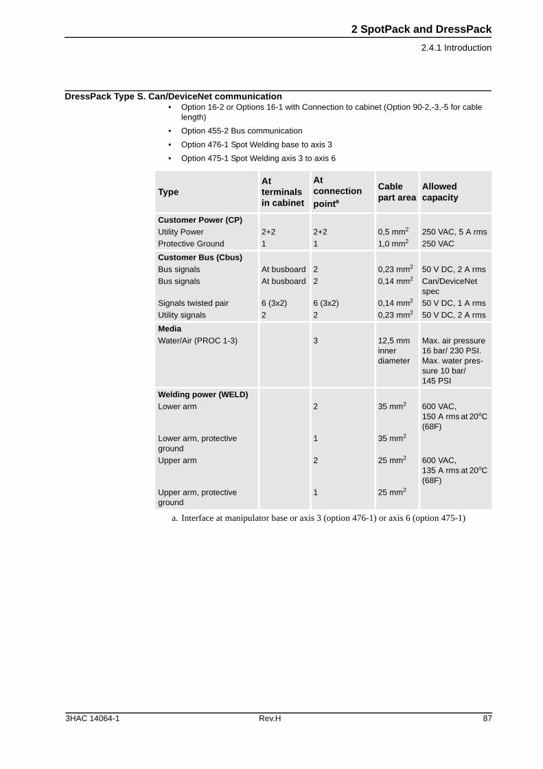
2 SpotPack and DressPack
2.4.1 Introduction
DressPack Type S. Can/DeviceNet communication• Option 16-2 or Options 16-1 with Connection to cabinet (Option 90-2,-3,-5 for cable
length)
• Option 455-2 Bus communication
• Option 476-1 Spot Welding base to axis 3
• Option 475-1 Spot Welding axis 3 to axis 6
TypeAt terminals in cabinet
At connection pointa
a. Interface at manipulator base or axis 3 (option 476-1) or axis 6 (option 475-1)
Cable part area
Allowed capacity
Customer Power (CP)Utility Power
Protective Ground
2+2
1
2+2
1
0,5 mm2
1,0 mm2
250 VAC, 5 A rms
250 VAC
Customer Bus (Cbus)Bus signals
Bus signals
Signals twisted pair
Utility signals
At busboard
At busboard
6 (3x2)
2
2
2
6 (3x2)
2
0,23 mm2
0,14 mm2
0,14 mm2
0,23 mm2
50 V DC, 2 A rms
Can/DeviceNet spec
50 V DC, 1 A rms
50 V DC, 2 A rms
MediaWater/Air (PROC 1-3) 3 12,5 mm
inner diameter
Max. air pressure 16 bar/ 230 PSI. Max. water pres-sure 10 bar/ 145 PSI
Welding power (WELD)Lower arm
Lower arm, protective ground
Upper arm
Upper arm, protective ground
2
1
2
1
35 mm2
35 mm2
25 mm2
25 mm2
600 VAC, 150 A rms at 20oC (68F)
600 VAC, 135 A rms at 20oC (68F)
3HAC 14064-1 Rev.H 87
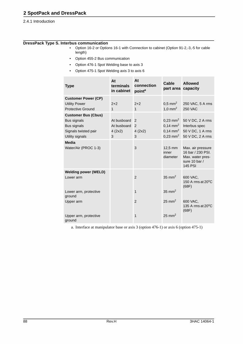
2 SpotPack and DressPack
2.4.1 Introduction
DressPack Type S. Interbus communication• Option 16-2 or Options 16-1 with Connection to cabinet (Option 91-2,-3,-5 for cable
length)
• Option 455-2 Bus communication
• Option 476-1 Spot Welding base to axis 3
• Option 475-1 Spot Welding axis 3 to axis 6
TypeAt terminals in cabinet
At connection pointa
a. Interface at manipulator base or axis 3 (option 476-1) or axis 6 (option 475-1)
Cable part area
Allowed capacity
Customer Power (CP)Utility Power
Protective Ground
2+2
1
2+2
1
0,5 mm2
1,0 mm2
250 VAC, 5 A rms
250 VAC
Customer Bus (Cbus)Bus signals
Bus signals
Signals twisted pair
Utility signals
At busboard
At busboard
4 (2x2)
3
2
2
4 (2x2)
3
0,23 mm2
0,14 mm2
0,14 mm2
0,23 mm2
50 V DC, 2 A rms
Interbus spec
50 V DC, 1 A rms
50 V DC, 2 A rms
MediaWater/Air (PROC 1-3) 3 12,5 mm
inner diameter
Max. air pressure 16 bar / 230 PSI. Max. water pres-sure 10 bar / 145 PSI
Welding power (WELD)Lower arm
Lower arm, protective ground
Upper arm
Upper arm, protective ground
2
1
2
1
35 mm2
35 mm2
25 mm2
25 mm2
600 VAC, 150 A rms at 20oC (68F)
600 VAC, 135 A rms at 20oC (68F)
88 Rev.H 3HAC 14064-1
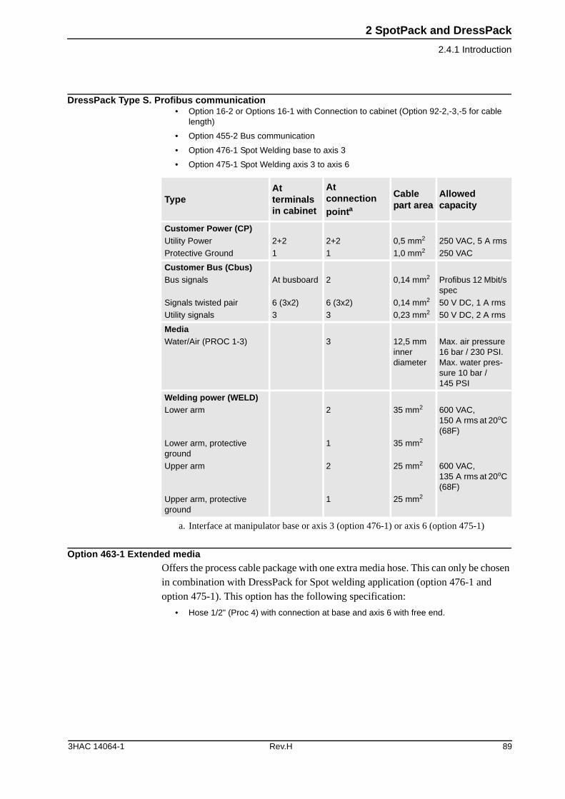
2 SpotPack and DressPack
2.4.1 Introduction
DressPack Type S. Profibus communication• Option 16-2 or Options 16-1 with Connection to cabinet (Option 92-2,-3,-5 for cable
length)
• Option 455-2 Bus communication
• Option 476-1 Spot Welding base to axis 3
• Option 475-1 Spot Welding axis 3 to axis 6
Option 463-1 Extended mediaOffers the process cable package with one extra media hose. This can only be chosen in combination with DressPack for Spot welding application (option 476-1 and option 475-1). This option has the following specification:
• Hose 1/2" (Proc 4) with connection at base and axis 6 with free end.
TypeAt terminals in cabinet
At connection pointa
a. Interface at manipulator base or axis 3 (option 476-1) or axis 6 (option 475-1)
Cable part area
Allowed capacity
Customer Power (CP)Utility Power
Protective Ground
2+2
1
2+2
1
0,5 mm2
1,0 mm2
250 VAC, 5 A rms
250 VAC
Customer Bus (Cbus)Bus signals
Signals twisted pair
Utility signals
At busboard
6 (3x2)
3
2
6 (3x2)
3
0,14 mm2
0,14 mm2
0,23 mm2
Profibus 12 Mbit/s spec
50 V DC, 1 A rms
50 V DC, 2 A rms
MediaWater/Air (PROC 1-3) 3 12,5 mm
inner diameter
Max. air pressure 16 bar / 230 PSI. Max. water pres-sure 10 bar / 145 PSI
Welding power (WELD)Lower arm
Lower arm, protective ground
Upper arm
Upper arm, protective ground
2
1
2
1
35 mm2
35 mm2
25 mm2
25 mm2
600 VAC, 150 A rms at 20oC (68F)
600 VAC, 135 A rms at 20oC (68F)
3HAC 14064-1 Rev.H 89
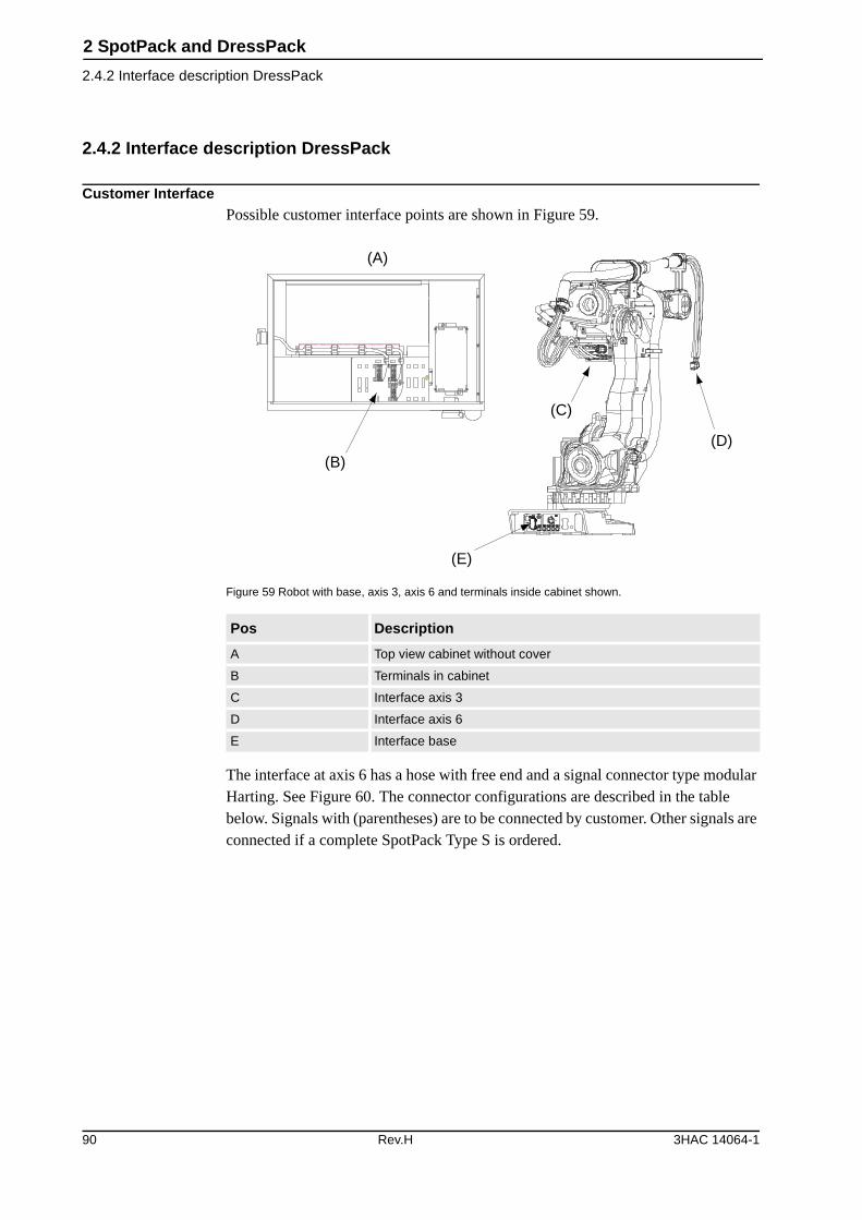
2 SpotPack and DressPack
2.4.2 Interface description DressPack
2.4.2 Interface description DressPack
Customer InterfacePossible customer interface points are shown in Figure 59.
Figure 59 Robot with base, axis 3, axis 6 and terminals inside cabinet shown.
The interface at axis 6 has a hose with free end and a signal connector type modular Harting. See Figure 60. The connector configurations are described in the table below. Signals with (parentheses) are to be connected by customer. Other signals are connected if a complete SpotPack Type S is ordered.
Pos Description
A Top view cabinet without cover
B Terminals in cabinet
C Interface axis 3
D Interface axis 6
E Interface base
XT6 XT5.1
(A)
(B)
(C)
(D)
(E)
90 Rev.H 3HAC 14064-1
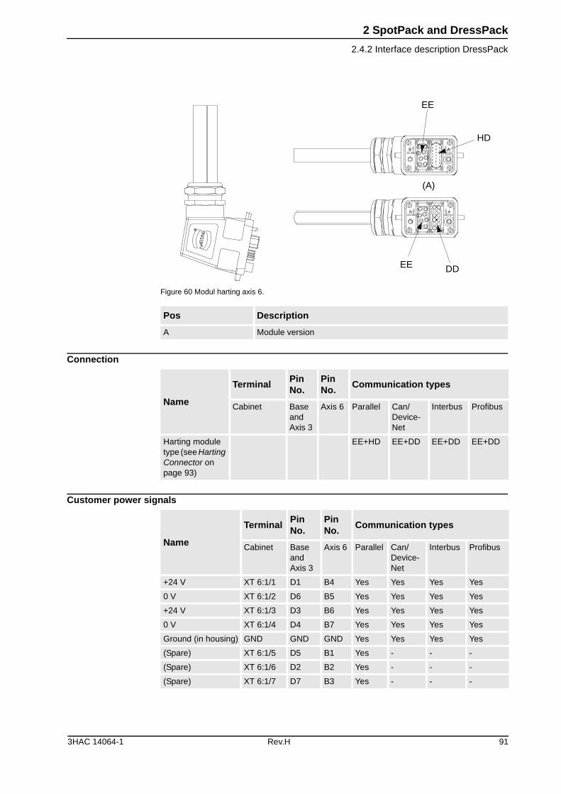
2 SpotPack and DressPack
2.4.2 Interface description DressPack
Figure 60 Modul harting axis 6.
Connection
Customer power signals
Pos Description
A Module version
EE
HD
DDEE
(A)
Name
TerminalPin No.
Pin No.
Communication types
Cabinet Base and Axis 3
Axis 6 Parallel Can/ Device- Net
Interbus Profibus
Harting module type (see Harting Connector on page 93)
EE+HD EE+DD EE+DD EE+DD
Name
TerminalPin No.
Pin No.
Communication types
Cabinet Base and Axis 3
Axis 6 Parallel Can/ Device- Net
Interbus Profibus
+24 V XT 6:1/1 D1 B4 Yes Yes Yes Yes
0 V XT 6:1/2 D6 B5 Yes Yes Yes Yes
+24 V XT 6:1/3 D3 B6 Yes Yes Yes Yes
0 V XT 6:1/4 D4 B7 Yes Yes Yes Yes
Ground (in housing) GND GND GND Yes Yes Yes Yes
(Spare) XT 6:1/5 D5 B1 Yes - - -
(Spare) XT 6:1/6 D2 B2 Yes - - -
(Spare) XT 6:1/7 D7 B3 Yes - - -
3HAC 14064-1 Rev.H 91
2 SpotPack and DressPack
2.4.2 Interface description DressPack
Customer signals
Name
Terminal Pin No. Pin No. Communication types
Cabinet Base and Axis 3
Axis 6 Parallel Can/ Device- Net
Inter-bus
Profi-bus
(Spare) XT 5:1/1 B1 A18 Yes - - -
(Spare) XT 5:1/2 B2 A19 Yes - - -
(Spare) Sep. screened
XT 5:2/17 B3 A20 Yes - - -
(Spare) Sep. screened
XT 5:2/18 B4 A21 Yes - - -
(Spare) Sep. screened
XT 5:2/21 B5 A22 Yes - - -
(Spare) Sep. screened
XT 5:2/22 B6 A23 Yes - - -
KSR Sep. screened
XT 5:2/13 B7 A24 Yes - - -
KSR Sep. screened
XT 5:2/14 B8 A25 Yes - - -
(Spare) Sep. screened
XT 5:2/15 B9 A16 Yes - - -
(Spare) Sep. screened
XT 5:2/16 B10 A17 Yes - - -
Close_tip1(DO 1)
XT 5:1/3 B11 A1 Yes - - -
Temp_ok (DI 8) XT 5:1/4 B12 A2 Yes - - -
Work_select (DO 8)
XT 5:1/5 B13 A3 Yes - - -
Tip1_open (DI 9) XT 5:1/6 B14 A4 Yes - - -
Tip1_retract(DI 10)
XT 5:1/7 B15 A5 Yes - - -
(Spare) XT 5:1/8 B16 A6 Yes - - -
(Spare) XT 5:1/9 B18 A7 Yes - - -
(Spare) XT 5:1/10 B19 A8 Yes - - -
(Spare) XT 5:1/11 B20 A9 Yes - - -
(Spare) XT 5:1/12 B21 A10 Yes - - -
(Spare) XT 5:2/19 C1 A11 Yes - - -
(Spare) XT 5:2/20 C2 A12 Yes - - -
(Spare) XT 5:2/23 C3 A13 Yes - - -
(Spare) XT 5:2/24 C4 A14 Yes - - -
Not in use - - - - - - -
92 Rev.H 3HAC 14064-1
2 SpotPack and DressPack
2.4.2 Interface description DressPack
CBus signals
Harting ConnectorThe Harting connector is shown below. The different main parts within the connec-tor are shown both with name and Hartings article number. Corresponding parts at the tool are available within the Harting product offer.
For the contacts above corresponding female crimp-contacts for the different cable diameters are required.
Name
TerminalPin No.
Pin No.
Communication types
Cabinet Base and Axis 3
Axis 6
Par-allel
Can/ DeviceNet
Interbus Profibus
(Spare) or Bus signals
See valid bus
B22 A1 +24VCAN GNDIM XT 5:2/21
(Spare) or Bus signals
See valid bus
B23 A2 0V CAN XT 5:2/18 XT 5:2/22
(Spare) See valid bus
B24 A3 XT 5:2/19 XT 5:2/19 XT 5:2/19
(Spare) See valid bus
B25 A4 XT 5:2/20 XT 5:2/20 XT 5:2/20
(Spare) or Bus signals
See valid bus
A3 A7 CAN1X H XT 5:2/15 XT 5:2/13/KSR
(Spare) or Bus signals
See valid bus
A4 A8 CAN1X L XT 5:2/16 XT 5:2/14/KSR
(Spare) or Bus signals
See valid bus
A5 A9 XT 5:2/13/KSR
XT 5:2/13 RXD/TXD-P
(Spare) or Bus signals
See valid bus
A6 A10 XT 5:2/14/KSR
XT 5:2/14 RXD/TXD-N
(Spare) or Bus signals
See valid bus
A9 A5 XT 5:2/15 DO XT 5:2/15
(Spare) or Bus signals
See valid bus
A10 A6 XT 5:2/16 DO_N XT 5:2/16
(Spare) or Bus signals
See valid bus
A11 A11 XT 5:2/17 DO XT 5:2/17
(Spare) or Bus signals
See valid bus
A12 A12 XT 5:2/18 DO_N XT 5:2/18
Name Harting article No.
Hood 09 30 006 0543
Hinged frame, hood 09 14 006 0303
Multicontact, female (HD) 09 14 025 3101
Multicontact, female (EE) 09 14 012 3101
Multicontact, female (DD) 09 14 008 3101
3HAC 14064-1 Rev.H 93
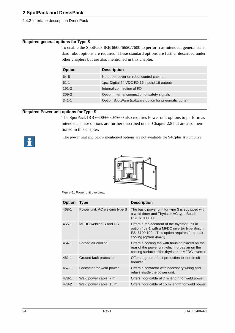
2 SpotPack and DressPack
2.4.2 Interface description DressPack
Required general options for Type S To enable the SpotPack IRB 6600/6650/7600 to perform as intended, general stan-dard robot options are required. These standard options are further described under other chapters but are also mentioned in this chapter.
Required Power unit options for Type SThe SpotPack IRB 6600/6650/7600 also requires Power unit options to perform as intended. These options are further described under Chapter 2.8 but are also men-tioned in this chapter.
Figure 61 Power unit overview.
Option Description
64-5 No upper cover on robot control cabinet
61-1 1pc. Digital 24 VDC I/O 16 inputs/ 16 outputs
191-3 Internal connection of I/O
309-3 Option Internal connection of safety signals
341-1 Option SpotWare (software option for pneumatic guns)
The power unit and below mentioned options are not available for S4Cplus Automotive
Option Type Description
468-1 Power unit, AC welding type S The basic power unit for type S is equipped with a weld timer and Thyristor AC type Bosch PST 6100.100L.
465-1 MFDC welding S and HS Offers a replacement of the thyristor unit in option 468-1 with a MFDC inverter type Bosch PSI 6100.100L. This option requires forced air cooling (option 464-1).
464-1 Forced air cooling Offers a cooling fan with housing placed on the rear of the power unit which forces air on the cooling surface of the thyristor or MFDC inverter.
461-1 Ground fault protection Offers a ground fault protection to the circuit breaker.
457-1 Contactor for weld power Offers a contactor with necessary wiring and relays inside the power unit.
478-1 Weld power cable, 7 m Offers floor cable of 7 m length for weld power.
478-2 Weld power cable, 15 m Offers floor cable of 15 m length for weld power.
94 Rev.H 3HAC 14064-1
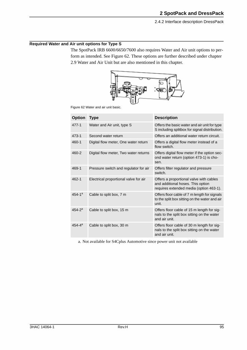
2 SpotPack and DressPack
2.4.2 Interface description DressPack
Required Water and Air unit options for Type S The SpotPack IRB 6600/6650/7600 also requires Water and Air unit options to per-form as intended. See Figure 62. These options are further described under chapter 2.9 Water and Air Unit but are also mentioned in this chapter.
Figure 62 Water and air unit basic.
Option Type Description
477-1 Water and Air unit, type S Offers the basic water and air unit for type S including splitbox for signal distribution.
473-1 Second water return Offers an additional water return circuit.
460-1 Digital flow meter, One water return Offers a digital flow meter instead of a flow switch.
460-2 Digital flow meter, Two water returns Offers digital flow meter if the option sec-ond water return (option 473-1) is cho-sen.
469-1 Pressure switch and regulator for air Offers filter regulator and pressure switch.
462-1 Electrical proportional valve for air Offers a proportional valve with cables and additional hoses. This option requires extended media (option 463-1).
454-1a
a. Not available for S4Cplus Automotive since power unit not available
Cable to split box, 7 m Offers floor cable of 7 m length for signals to the split box sitting on the water and air unit.
454-2a Cable to split box, 15 m Offers floor cable of 15 m length for sig-nals to the split box sitting on the water and air unit.
454-4a Cable to split box, 30 m Offers floor cable of 30 m length for sig-nals to the split box sitting on the water and air unit.
3HAC 14064-1 Rev.H 95
2 SpotPack and DressPack
2.4.3 Summary Type S
2.4.3 Summary Type S
The following options are required to form a complete SpotPack Type S:
DressPack
General options
Power unit
Water and air unit
(Also, option 462-1 and 463-1 at the water and air unit are normally required for pneumatic gun handling).
Other described options depends on specific system need and performance.
Option Description
16-1 Connection to cabinet (Cable length and communication type to be stated)
455-1 or -2 Parallel or Bus communication (Communication type to be stated)
476-1 Spot Welding base to axis 3 (DressPackage lower arm)
475-1 Spot Welding axis 3 to axis 6 (DressPackage upper arm)
Option Description
64-5 No upper cover on robot control cabinet
61-1 1pc. Digital 24 VDC I/O 16 inputs/ 16 outputs
191-3 Internal connection of I/O
309-3 Internal connection of safety signals
341-1 SpotWare (software option for pneumatic guns)
Option Description
468-1 Power unit AC
478-1 Power cable 7 m (other length available)
The power unit is not available for S4Cplus Automotive
Option Description
477-1 Water and air unit
454-1a
a. Not available for S4Cplus Automotive
Splitbox cable 7 m. (other length availible)
96 Rev.H 3HAC 14064-1
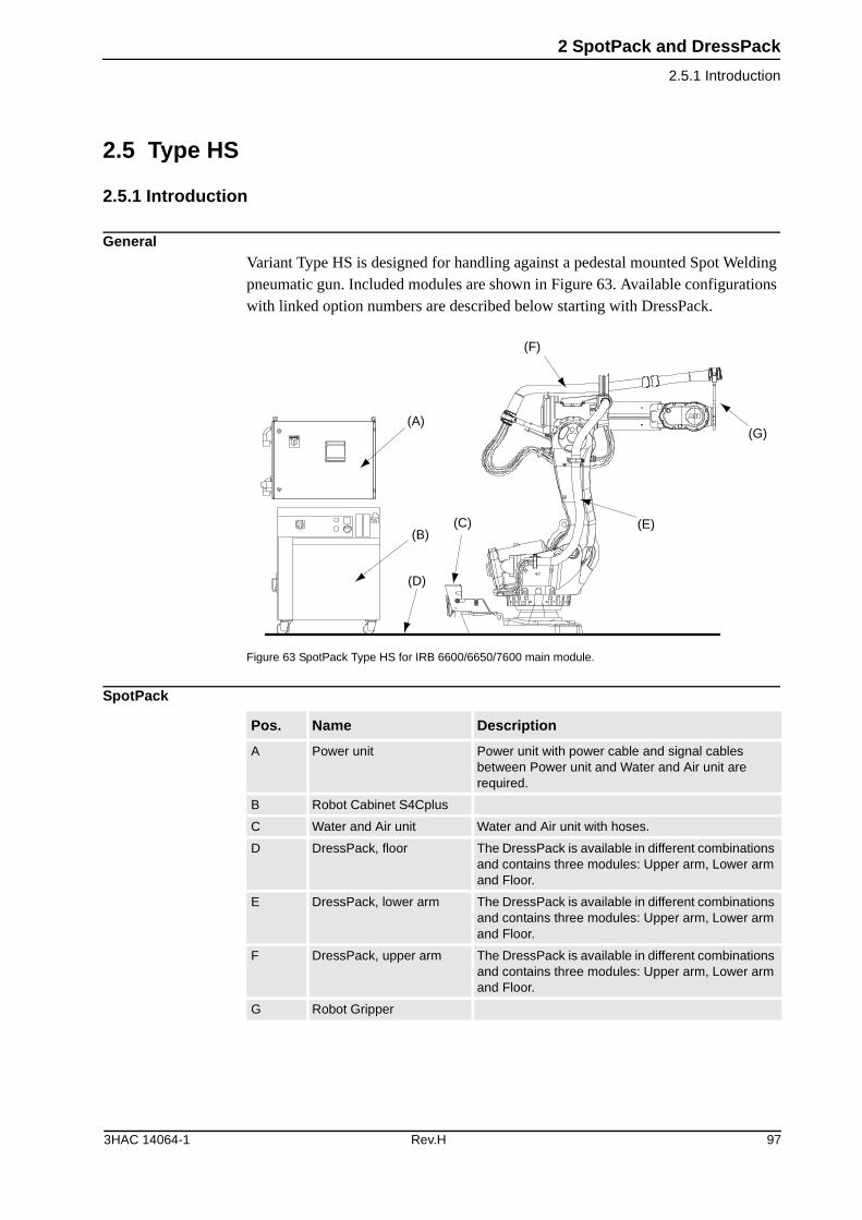
2 SpotPack and DressPack
2.5.1 Introduction
2.5 Type HS
2.5.1 Introduction
GeneralVariant Type HS is designed for handling against a pedestal mounted Spot Welding pneumatic gun. Included modules are shown in Figure 63. Available configurations with linked option numbers are described below starting with DressPack.
Figure 63 SpotPack Type HS for IRB 6600/6650/7600 main module.
SpotPack
(A)
(B)(C)
(D)
(F)
(E)
(G)
Pos. Name Description
A Power unit Power unit with power cable and signal cables between Power unit and Water and Air unit are required.
B Robot Cabinet S4Cplus
C Water and Air unit Water and Air unit with hoses.
D DressPack, floor The DressPack is available in different combinations and contains three modules: Upper arm, Lower arm and Floor.
E DressPack, lower arm The DressPack is available in different combinations and contains three modules: Upper arm, Lower arm and Floor.
F DressPack, upper arm The DressPack is available in different combinations and contains three modules: Upper arm, Lower arm and Floor.
G Robot Gripper
3HAC 14064-1 Rev.H 97
2 SpotPack and DressPack
2.5.1 Introduction
Depending on the choice of Parallel or Bus communication the process cable pack-age for option 538-1 and option 466-1 will have different content. See tables for:
• DressPack Type HS. Parallel communication
• DressPack Type HS. Can/DeviceNet communication
• DressPack Type HS. Interbus communication
• DressPack Type HS. Profibus communication below
Option Type Description
16-2 Connection to manipulator No Floor harness for the DressPack is chosen.
16-1 Connection to cabinet Floor cables for the DressPack are chosen. The length and configuration of the floor harness is specified under the options below. The required options must be specified in the specification form:
Option 94-1,-2,-4 for parallel communication
Option 90-2,-3,-5 for bus communication with Can/DeviceNet
Option 92-2,-3,-5 for bus communication with Profi-bus
Option 91-2,-3,-4 for bus communication with Inter-bus
455-1 Parallel communication Offers the process cable package needed for paral-lel communication.
455-2 Bus communication Offers the process cable package needed for bus communication. This option includes both the sig-nals for the bus communication as well as some parallel signals. The type of bus is defined by the choice of the floor cabling (see option 16-1 above).
455-3 Basic Parallel communica-tion
Offers the process cable package needed for the basic parallel communication.
538-1 Material handling base to axis 3
Offers DressPack from robot base to axis 3 for Material Handling application.
466-1 Material handling axis 3 to axis 6
Offers DressPack from axis 3 to axis 6 for Material Handling application.
98 Rev.H 3HAC 14064-1
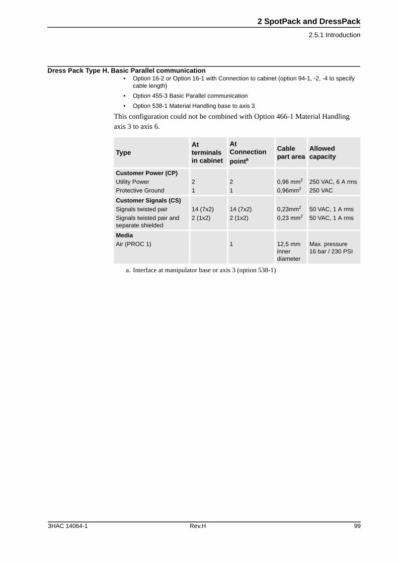
2 SpotPack and DressPack
2.5.1 Introduction
Dress Pack Type H. Basic Parallel communication• Option 16-2 or Option 16-1 with Connection to cabinet (option 94-1, -2, -4 to specify
cable length)
• Option 455-3 Basic Parallel communication
• Option 538-1 Material Handling base to axis 3
This configuration could not be combined with Option 466-1 Material Handling axis 3 to axis 6.
TypeAt terminals in cabinet
At Connection pointa
a. Interface at manipulator base or axis 3 (option 538-1)
Cable part area
Allowed capacity
Customer Power (CP)Utility Power
Protective Ground
2
1
2
1
0,96 mm2
0,96mm2
250 VAC, 6 A rms
250 VAC
Customer Signals (CS)Signals twisted pair
Signals twisted pair and separate shielded
14 (7x2)
2 (1x2)
14 (7x2)
2 (1x2)
0,23mm2
0,23 mm2
50 VAC, 1 A rms
50 VAC, 1 A rms
MediaAir (PROC 1) 1 12,5 mm
inner diameter
Max. pressure 16 bar / 230 PSI
3HAC 14064-1 Rev.H 99
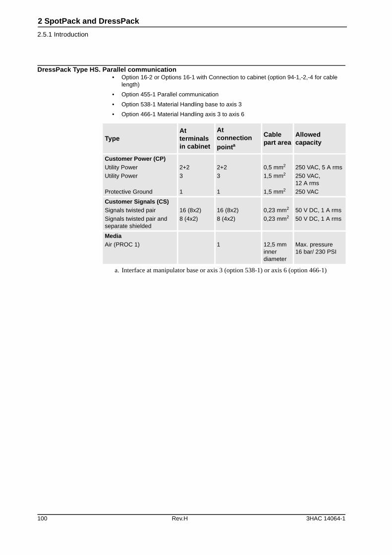
2 SpotPack and DressPack
2.5.1 Introduction
DressPack Type HS. Parallel communication• Option 16-2 or Options 16-1 with Connection to cabinet (option 94-1,-2,-4 for cable
length)
• Option 455-1 Parallel communication
• Option 538-1 Material Handling base to axis 3
• Option 466-1 Material Handling axis 3 to axis 6
TypeAt terminals in cabinet
At connection pointa
a. Interface at manipulator base or axis 3 (option 538-1) or axis 6 (option 466-1)
Cable part area
Allowed capacity
Customer Power (CP)Utility Power
Utility Power
Protective Ground
2+2
3
1
2+2
3
1
0,5 mm2
1,5 mm2
1,5 mm2
250 VAC, 5 A rms
250 VAC, 12 A rms
250 VAC
Customer Signals (CS)Signals twisted pair
Signals twisted pair and separate shielded
16 (8x2)
8 (4x2)
16 (8x2)
8 (4x2)
0,23 mm2
0,23 mm2
50 V DC, 1 A rms
50 V DC, 1 A rms
MediaAir (PROC 1) 1 12,5 mm
inner diameter
Max. pressure 16 bar/ 230 PSI
100 Rev.H 3HAC 14064-1
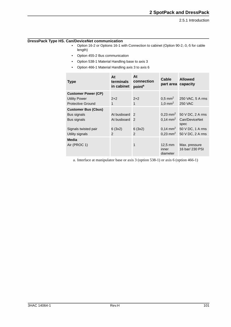
2 SpotPack and DressPack
2.5.1 Introduction
DressPack Type HS. Can/DeviceNet communication• Option 16-2 or Options 16-1 with Connection to cabinet (Option 90-2,-3,-5 for cable
length)
• Option 455-2 Bus communication
• Option 538-1 Material Handling base to axis 3
• Option 466-1 Material Handling axis 3 to axis 6
TypeAt terminals in cabinet
At connection pointa
a. Interface at manipulator base or axis 3 (option 538-1) or axis 6 (option 466-1)
Cable part area
Allowed capacity
Customer Power (CP)Utility Power
Protective Ground
2+2
1
2+2
1
0,5 mm2
1,0 mm2
250 VAC, 5 A rms
250 VAC
Customer Bus (Cbus)Bus signals
Bus signals
Signals twisted pair
Utility signals
At busboard
At busboard
6 (3x2)
2
2
2
6 (3x2)
2
0,23 mm2
0,14 mm2
0,14 mm2
0,23 mm2
50 V DC, 2 A rms
Can/DeviceNet spec
50 V DC, 1 A rms
50 V DC, 2 A rms
MediaAir (PROC 1) 1 12,5 mm
inner diameter
Max. pressure 16 bar/ 230 PSI
3HAC 14064-1 Rev.H 101
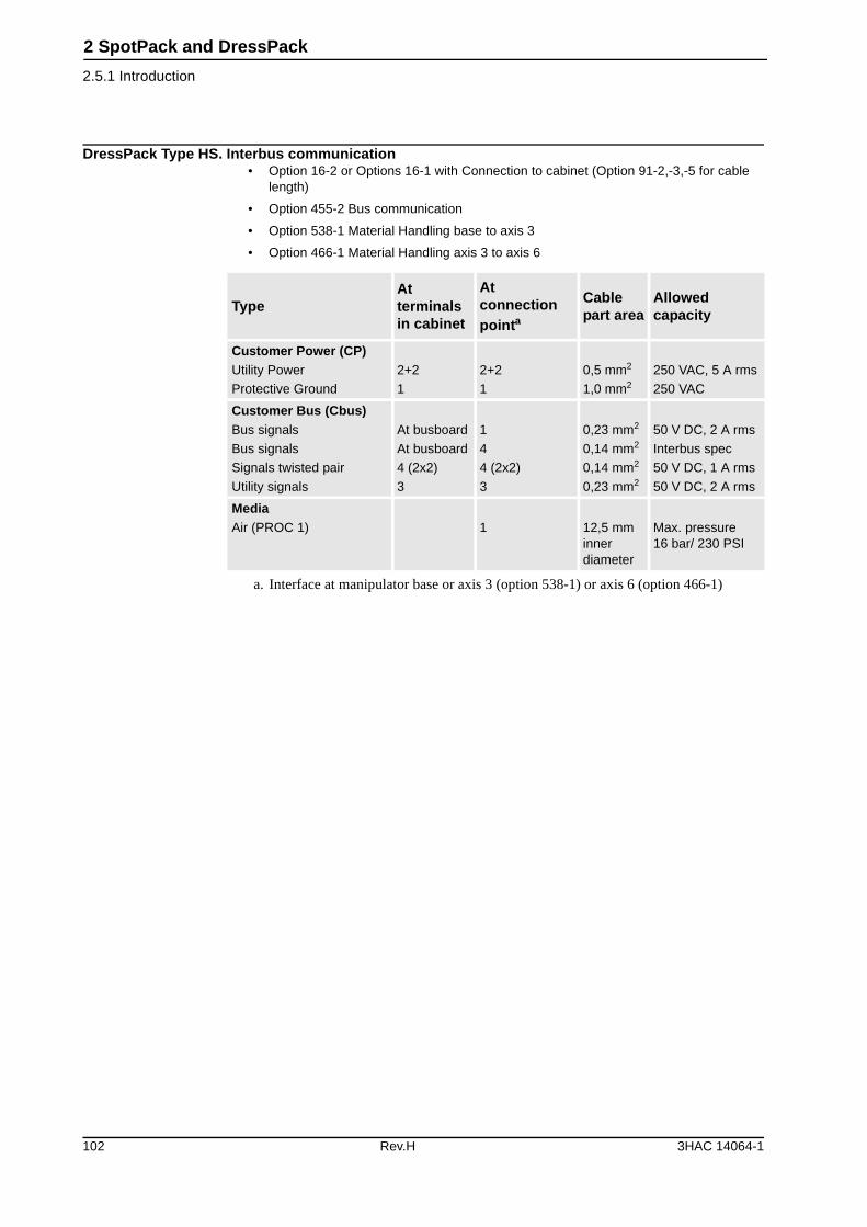
2 SpotPack and DressPack
2.5.1 Introduction
DressPack Type HS. Interbus communication• Option 16-2 or Options 16-1 with Connection to cabinet (Option 91-2,-3,-5 for cable
length)
• Option 455-2 Bus communication
• Option 538-1 Material Handling base to axis 3
• Option 466-1 Material Handling axis 3 to axis 6
TypeAt terminals in cabinet
At connection pointa
a. Interface at manipulator base or axis 3 (option 538-1) or axis 6 (option 466-1)
Cable part area
Allowed capacity
Customer Power (CP)Utility Power
Protective Ground
2+2
1
2+2
1
0,5 mm2
1,0 mm2
250 VAC, 5 A rms
250 VAC
Customer Bus (Cbus)Bus signals
Bus signals
Signals twisted pair
Utility signals
At busboard
At busboard
4 (2x2)
3
1
4
4 (2x2)
3
0,23 mm2
0,14 mm2
0,14 mm2
0,23 mm2
50 V DC, 2 A rms
Interbus spec
50 V DC, 1 A rms
50 V DC, 2 A rms
MediaAir (PROC 1) 1 12,5 mm
inner diameter
Max. pressure 16 bar/ 230 PSI
102 Rev.H 3HAC 14064-1
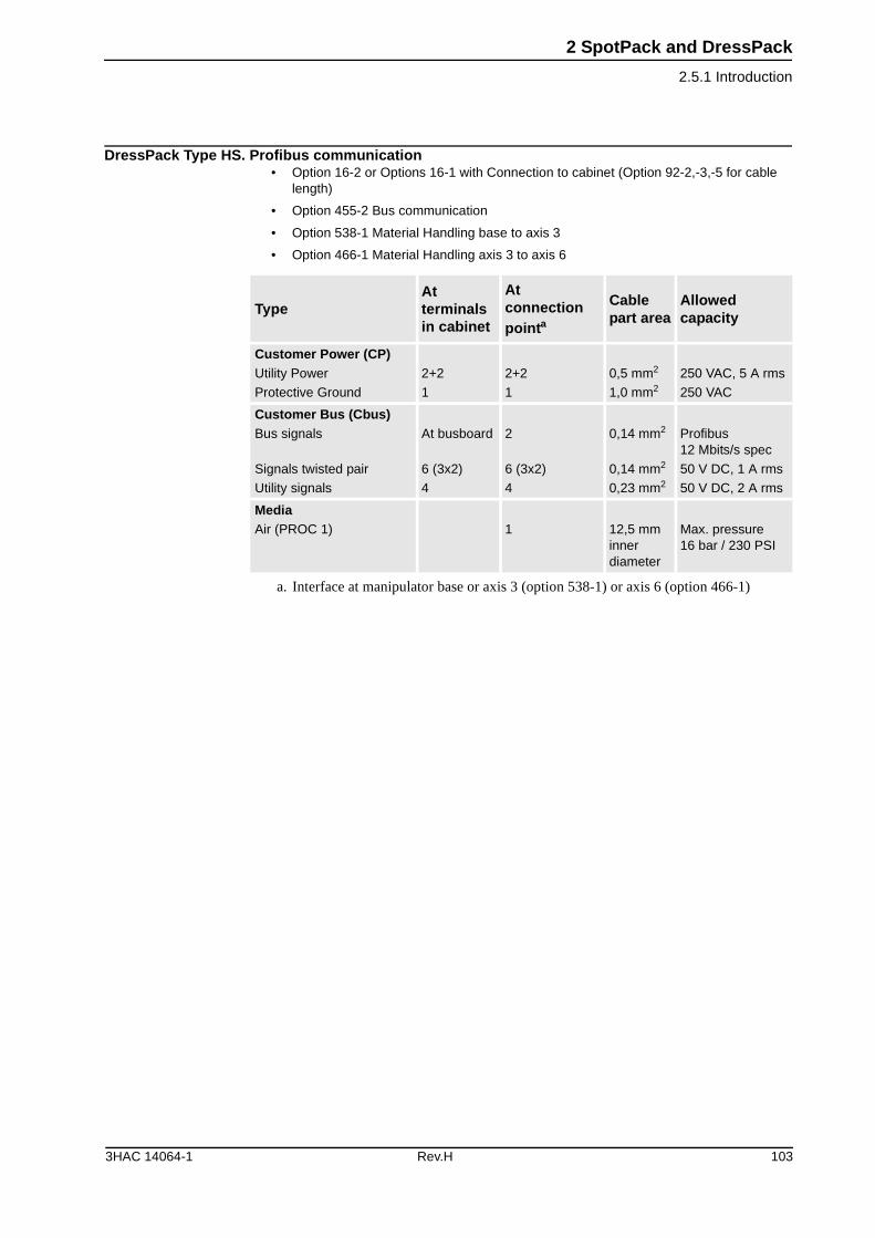
2 SpotPack and DressPack
2.5.1 Introduction
DressPack Type HS. Profibus communication• Option 16-2 or Options 16-1 with Connection to cabinet (Option 92-2,-3,-5 for cable
length)
• Option 455-2 Bus communication
• Option 538-1 Material Handling base to axis 3
• Option 466-1 Material Handling axis 3 to axis 6
TypeAt terminals in cabinet
At connection pointa
a. Interface at manipulator base or axis 3 (option 538-1) or axis 6 (option 466-1)
Cable part area
Allowed capacity
Customer Power (CP)Utility Power
Protective Ground
2+2
1
2+2
1
0,5 mm2
1,0 mm2
250 VAC, 5 A rms
250 VAC
Customer Bus (Cbus)Bus signals
Signals twisted pair
Utility signals
At busboard
6 (3x2)
4
2
6 (3x2)
4
0,14 mm2
0,14 mm2
0,23 mm2
Profibus12 Mbits/s spec
50 V DC, 1 A rms
50 V DC, 2 A rms
MediaAir (PROC 1) 1 12,5 mm
inner diameter
Max. pressure 16 bar / 230 PSI
3HAC 14064-1 Rev.H 103
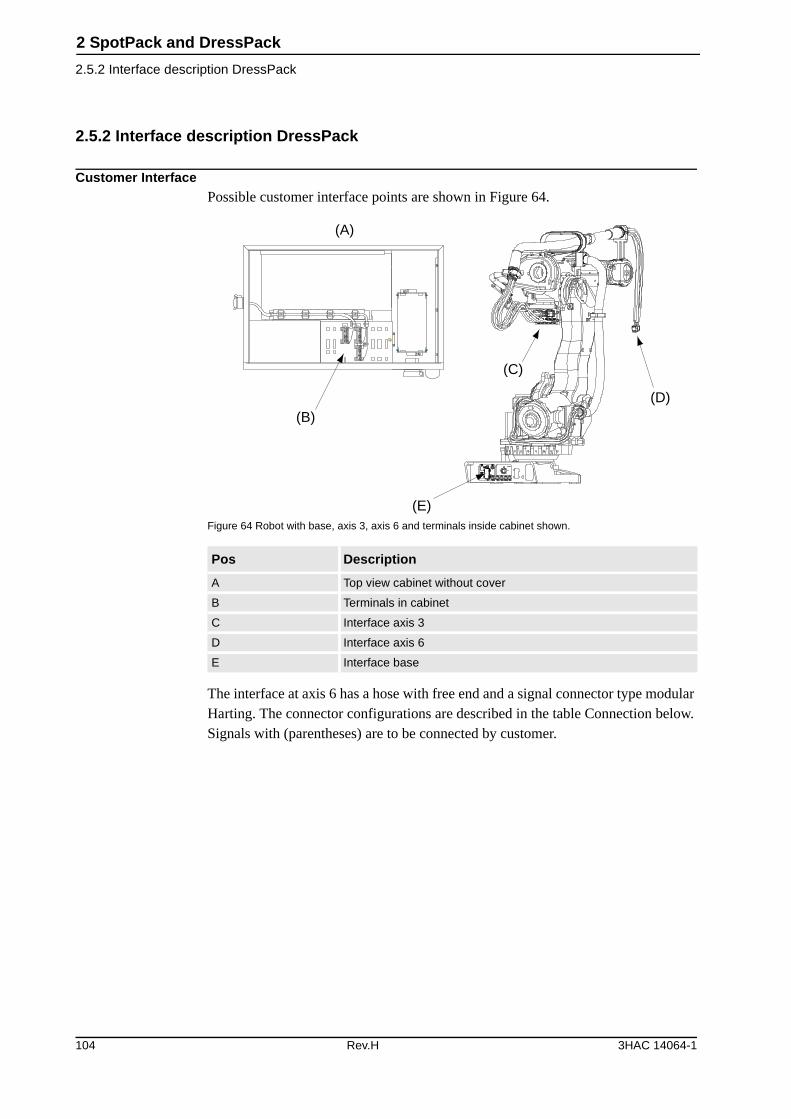
2 SpotPack and DressPack
2.5.2 Interface description DressPack
2.5.2 Interface description DressPack
Customer InterfacePossible customer interface points are shown in Figure 64.
Figure 64 Robot with base, axis 3, axis 6 and terminals inside cabinet shown.
The interface at axis 6 has a hose with free end and a signal connector type modular Harting. The connector configurations are described in the table Connection below. Signals with (parentheses) are to be connected by customer.
Pos Description
A Top view cabinet without cover
B Terminals in cabinet
C Interface axis 3
D Interface axis 6
E Interface base
XT6 XT5.1
(A)
(B)
(C)
(D)
(E)
104 Rev.H 3HAC 14064-1
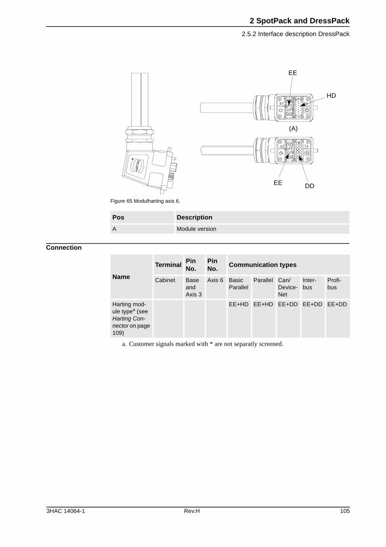
2 SpotPack and DressPack
2.5.2 Interface description DressPack
Figure 65 Modulharting axis 6.
Connection
Pos Description
A Module version
EE
HD
DDEE
(A)
Name
TerminalPin No.
Pin No.
Communication types
Cabinet Base and Axis 3
Axis 6 Basic Parallel
Parallel Can/ Device-Net
Inter-bus
Profi-bus
Harting mod-ule typea (see Harting Con-nector on page 109)
a. Customer signals marked with * are not separatly screened.
EE+HD EE+HD EE+DD EE+DD EE+DD
3HAC 14064-1 Rev.H 105
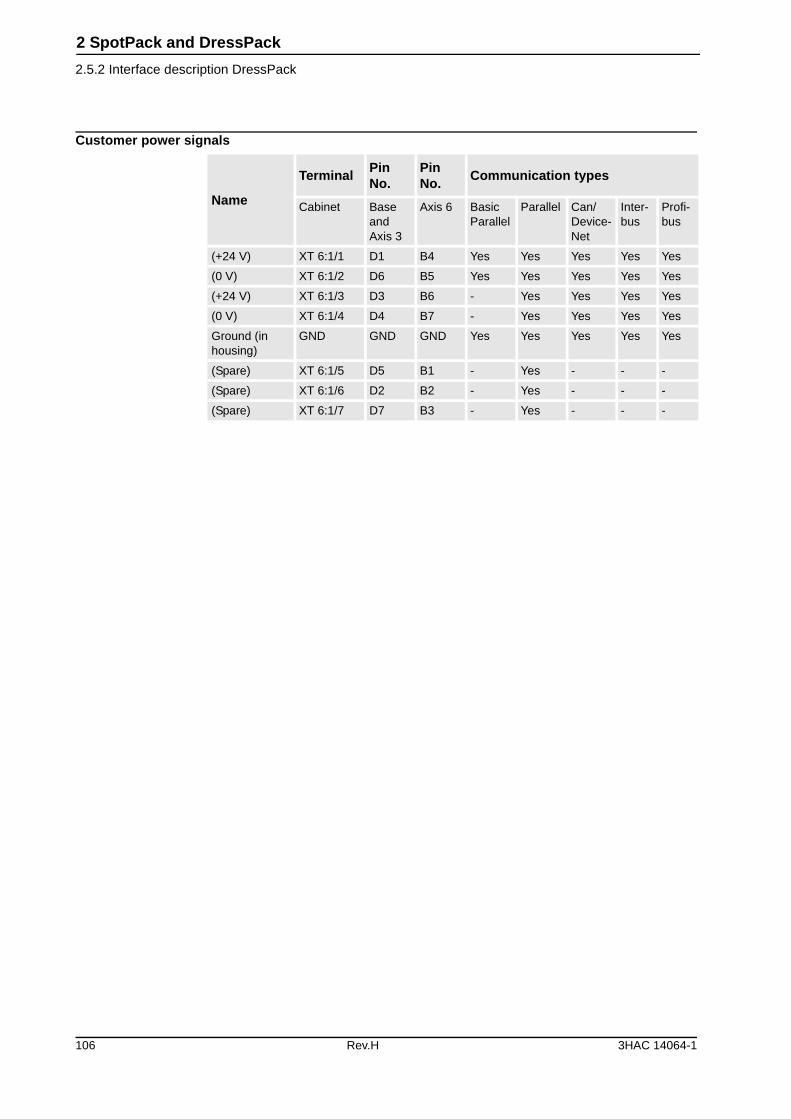
2 SpotPack and DressPack
2.5.2 Interface description DressPack
Customer power signals
Name
TerminalPin No.
Pin No.
Communication types
Cabinet Base and Axis 3
Axis 6 Basic Parallel
Parallel Can/ Device-Net
Inter-bus
Profi-bus
(+24 V) XT 6:1/1 D1 B4 Yes Yes Yes Yes Yes
(0 V) XT 6:1/2 D6 B5 Yes Yes Yes Yes Yes
(+24 V) XT 6:1/3 D3 B6 - Yes Yes Yes Yes
(0 V) XT 6:1/4 D4 B7 - Yes Yes Yes Yes
Ground (in housing)
GND GND GND Yes Yes Yes Yes Yes
(Spare) XT 6:1/5 D5 B1 - Yes - - -
(Spare) XT 6:1/6 D2 B2 - Yes - - -
(Spare) XT 6:1/7 D7 B3 - Yes - - -
106 Rev.H 3HAC 14064-1
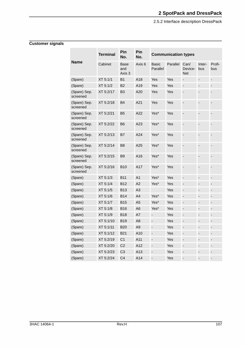
2 SpotPack and DressPack
2.5.2 Interface description DressPack
Customer signals
Name
TerminalPin No.
Pin No.
Communication types
Cabinet Base and Axis 3
Axis 6 Basic Parallel
Parallel Can/ Device-Net
Inter-bus
Profi-bus
(Spare) XT 5:1/1 B1 A18 Yes Yes - - -
(Spare) XT 5:1/2 B2 A19 Yes Yes - - -
(Spare) Sep. screened
XT 5:2/17 B3 A20 Yes Yes - - -
(Spare) Sep. screened
XT 5:2/18 B4 A21 Yes Yes - - -
(Spare) Sep. screened
XT 5:2/21 B5 A22 Yes* Yes - - -
(Spare) Sep. screened
XT 5:2/22 B6 A23 Yes* Yes - - -
(Spare) Sep. screened
XT 5:2/13 B7 A24 Yes* Yes - - -
(Spare) Sep. screened
XT 5:2/14 B8 A25 Yes* Yes - - -
(Spare) Sep. screened
XT 5:2/15 B9 A16 Yes* Yes - - -
(Spare) Sep. screened
XT 5:2/16 B10 A17 Yes* Yes - - -
(Spare) XT 5:1/3 B11 A1 Yes* Yes - - -
(Spare) XT 5:1/4 B12 A2 Yes* Yes - - -
(Spare) XT 5:1/5 B13 A3 Yes - - -
(Spare) XT 5:1/6 B14 A4 Yes* Yes - - -
(Spare) XT 5:1/7 B15 A5 Yes* Yes - - -
(Spare) XT 5:1/8 B16 A6 Yes* Yes - - -
(Spare) XT 5:1/9 B18 A7 - Yes - - -
(Spare) XT 5:1/10 B19 A8 - Yes - - -
(Spare) XT 5:1/11 B20 A9 - Yes - - -
(Spare) XT 5:1/12 B21 A10 - Yes - - -
(Spare) XT 5:2/19 C1 A11 - Yes - - -
(Spare) XT 5:2/20 C2 A12 - Yes - - -
(Spare) XT 5:2/23 C3 A13 - Yes - - -
(Spare) XT 5:2/24 C4 A14 - Yes - - -
3HAC 14064-1 Rev.H 107
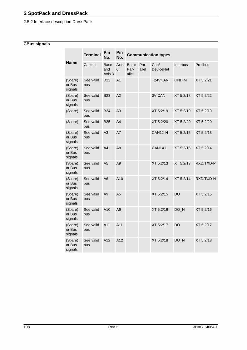
2 SpotPack and DressPack
2.5.2 Interface description DressPack
CBus signals
Name
TerminalPin No.
Pin No.
Communication types
Cabinet Base and Axis 3
Axis 6
Basic Par-allel
Par-allel
Can/ DeviceNet
Interbus Profibus
(Spare) or Bus signals
See valid bus
B22 A1 +24VCAN GNDIM XT 5:2/21
(Spare) or Bus signals
See valid bus
B23 A2 0V CAN XT 5:2/18 XT 5:2/22
(Spare) See valid bus
B24 A3 XT 5:2/19 XT 5:2/19 XT 5:2/19
(Spare) See valid bus
B25 A4 XT 5:2/20 XT 5:2/20 XT 5:2/20
(Spare) or Bus signals
See valid bus
A3 A7 CAN1X H XT 5:2/15 XT 5:2/13
(Spare) or Bus signals
See valid bus
A4 A8 CAN1X L XT 5:2/16 XT 5:2/14
(Spare) or Bus signals
See valid bus
A5 A9 XT 5:2/13 XT 5:2/13 RXD/TXD-P
(Spare) or Bus signals
See valid bus
A6 A10 XT 5:2/14 XT 5:2/14 RXD/TXD-N
(Spare) or Bus signals
See valid bus
A9 A5 XT 5:2/15 DO XT 5:2/15
(Spare) or Bus signals
See valid bus
A10 A6 XT 5:2/16 DO_N XT 5:2/16
(Spare) or Bus signals
See valid bus
A11 A11 XT 5:2/17 DO XT 5:2/17
(Spare) or Bus signals
See valid bus
A12 A12 XT 5:2/18 DO_N XT 5:2/18
108 Rev.H 3HAC 14064-1
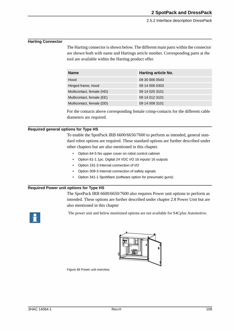
2 SpotPack and DressPack
2.5.2 Interface description DressPack
Harting ConnectorThe Harting connector is shown below. The different main parts within the connector are shown both with name and Hartings article number. Corresponding parts at the tool are available within the Harting product offer.
For the contacts above corresponding female crimp-contacts for the different cable diameters are required.
Required general options for Type HSTo enable the SpotPack IRB 6600/6650/7600 to perform as intended, general stan-dard robot options are required. These standard options are further described under other chapters but are also mentioned in this chapter.
• Option 64-5 No upper cover on robot control cabinet
• Option 61-1 1pc. Digital 24 VDC I/O 16 inputs/ 16 outputs
• Option 191-3 Internal connection of I/O
• Option 309-3 Internal connection of safety signals
• Option 341-1 SpotWare (software option for pneumatic guns)
Required Power unit options for Type HS The SpotPack IRB 6600/6650/7600 also requires Power unit options to perform as intended. These options are further described under chapter 2.8 Power Unit but are also mentioned in this chapter
Figure 66 Power unit overview.
Name Harting article No.
Hood 09 30 006 0543
Hinged frame, hood 09 14 006 0303
Multicontact, female (HD) 09 14 025 3101
Multicontact, female (EE) 09 14 012 3101
Multicontact, female (DD) 09 14 008 3101
The power unit and below mentioned options are not available for S4Cplus Automotive.
3HAC 14064-1 Rev.H 109

2 SpotPack and DressPack
2.5.2 Interface description DressPack
Option Type Description
468-2 Power unit, AC welding type HS
The basic power unit for type HS is equipped with a weld timer and Thyristor AC type Bosch PST 6100.100L.
465-1 MFDC welding type S and type HS
Offers a replacement of the thyristor unit in option 2088 with a MFDC inverter type Bosch PSI 6100.100L. This option requires forced air cooling (option 464-1).
464-1 Forced air cooling Offers a cooling fan with housing placed on the rear of the power unit which forces air on the cooling surface of the thyristor or MFDC inverter.
461-1 Ground fault protection Offers a ground fault protection to the circuit breaker.
457-1 Contactor for weld power Offers a contactor with necessary wiring and relays inside the power unit.
478-1 Weld power cable, 7 m Offers floor cable of 7 m length for weld power.
478-2 Weld power cable, 15 m Offers floor cable of 15 m length for weld power.
472-1 Process cable to station-ary gun, 7 m
Offers floor cable of 7 m length for signals to pedestal gun.
472-2 Process cable to station-ary gun, 15 m
Offers floor cable of 15 m length for signals to pedestal gun.
472-4 Process cable to station-ary gun, 30 m
Offers floor cable of 30 m length for signals to pedestal gun.
110 Rev.H 3HAC 14064-1
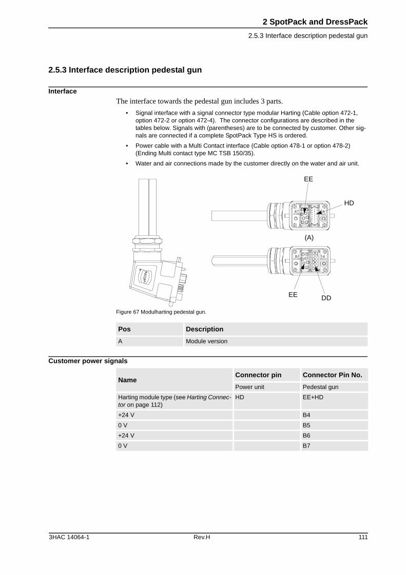
2 SpotPack and DressPack
2.5.3 Interface description pedestal gun
2.5.3 Interface description pedestal gun
InterfaceThe interface towards the pedestal gun includes 3 parts.
• Signal interface with a signal connector type modular Harting (Cable option 472-1, option 472-2 or option 472-4). The connector configurations are described in the tables below. Signals with (parentheses) are to be connected by customer. Other sig-nals are connected if a complete SpotPack Type HS is ordered.
• Power cable with a Multi Contact interface (Cable option 478-1 or option 478-2) (Ending Multi contact type MC TSB 150/35).
• Water and air connections made by the customer directly on the water and air unit.
Figure 67 Modulharting pedestal gun.
Customer power signals
Pos Description
A Module version
EE
HD
DDEE
(A)
NameConnector pin Connector Pin No.
Power unit Pedestal gun
Harting module type (see Harting Connec-tor on page 112)
HD EE+HD
+24 V B4
0 V B5
+24 V B6
0 V B7
3HAC 14064-1 Rev.H 111
2 SpotPack and DressPack
2.5.3 Interface description pedestal gun
Customer signals
Harting ConnectorThe Harting connector is shown in Figure 67. The different main parts within the connector are shown both with the name and Hartings article number. Corresponding parts at the tool are available within the Harting product offer.
For the contacts above corresponding female crimp-contacts for the different cable diameters are required.
NameConnector pin Connector Pin No.
Power unit Pedestal gun
Harting module type HD EE+HD
(Spare) A18
(Spare) A19
(Spare) A20
(Spare) A21
(Spare) A22
(Spare) A23
KSR Sep. screened A24
KSR Sep. screened A25
(Spare) Sep. screened A16
(Spare) Sep. screened A17
Close_tip1 (DO 1) A1
Temp_ok (DI 8) A2
Work_select (DO 8) A3
Tip1_open (DI 9) A4
Tip1_retract (DI 10) A5
(Spare) A6
Name Harting article No.
Hood 09 30 006 0543
Hinged frame, hood 09 14 006 0303
Multicontact, female (HD) 09 14 025 3101
Multicontact, female (EE) 09 14 012 3101
112 Rev.H 3HAC 14064-1
2 SpotPack and DressPack
2.5.3 Interface description pedestal gun
Required Water and Air unit options for Type HSThe SpotPack IRB 6600/6650/7600 also requires Water and Air unit options to per-form as intended. These options are further described under chapter 2.9 Water and Air Unit but are also mentioned in this chapter.
Figure 68 Water and air unit basic.
Option Type Description
477-2 Water and Air unit, type HS Offers the basic water and air unit for type HS including splitbox for signal distribution.
473-1 Second water return Offers an additional water return circuit.
460-1 Digital flow meter, One water return
Offers a digital flow meter instead of a flow switch.
460-2 Digital flow meter, Two water returns
Offers digital flow meter if the optional second water return (option 473-1) is chosen.
469-1 Pressure switch and regulator for air
Offers filter regulator and pressure switch.
462-1 Electrical proportional valve for air
Offers a proportional valve with cables and addi-tional hoses. This option requires extended media (option 463-1).
454-1a
a. Not available for S4Cplus Automotive since power unit not available
Cable to split box, 7 m Offers floor cable of 7 m length for signals to the split box sitting on the water and air unit.
454-2a Cable to split box, 15 m Offers floor cable of 15 m length for signals to the split box sitting on the water and air unit.
454-4a Cable to split box, 30 m Offers floor cable of 30 m length for signals to the split box sitting on the water and air unit.
3HAC 14064-1 Rev.H 113
2 SpotPack and DressPack
2.5.4 Summary Type HS
2.5.4 Summary Type HS
The following options are required to form a SpotPack Type HS:
DressPack
General options
Power unit
Water and air unit
(Also option 462-1 and 463-1 at water and air unit are normally required for pneu-matic gun handling).
Other described options depend on specific system need and performance.
Option Description
16-1 Connection to cabinet (Cable length and communication type to be stated)
455-1, 455-2, 455-3 Basic parallel, Parallel or Bus communication (Communication type to be stated)
538-1 Material Handling base to axis 3 (DressPackage lower arm)
466-1 Material Handling axis 3 to axis 6 (DressPackage upper arm)
Option Description
64-5 No upper cover on robot control cabinet
61-1 1pc. Digital 24 VDC I/O 16 inputs/ 16 outputs
191-3 Internal connection of I/O
309-3 Internal connection of safety signals
341-1 SpotWare (software option for pneumatic guns)
Option Description
468-2 Power unit AC type HS
478-1 Power cable 7 m (other length available)
472-1 Process cable to stationary gun, 7 m (other length available)
The power unit is not available for S4Cplus Automotive
Option Description
477-2 Water and air unit type HS
454-1a
a. Not available for S4Cplus Automotive
Splitbox cable 7 m. (other length available)
114 Rev.H 3HAC 14064-1
2 SpotPack and DressPack
2.6.1 Introduction
2.6 Type Se
2.6.1 Introduction
GeneralVariant Type Se is designed for Spot Welding application with robot handled servo-controlled tool (electrical gun). Included modules are shown in Figure 69. Available configurations with linked option numbers are described below starting with Dress-Pack.
Figure 69 SpotPack Type Se for IRB 6600/6650/7600 main modules.
SpotPack
(A)
(B)(C)
(D)
(F)
(E)
(G)
Pos Name Description
A Power unit Power unit with power cable and signal cables between Power unit and Water and Air unit are required.
B Robot Cabinet S4Cplus
C Water and Air unit Water and Air unit with hoses.
D DressPack, floor The DressPack is available in different combinations and contains three modules: Upper arm, Lower arm and Floor.
E DressPack, lower arm The DressPack is available in different combinations and contains three modules: Upper arm, Lower arm and Floor.
F DressPack, upper arm The DressPack is available in different combinations and contains three modules: Upper arm, Lower arm and Floor.
G Robot Gun
3HAC 14064-1 Rev.H 115
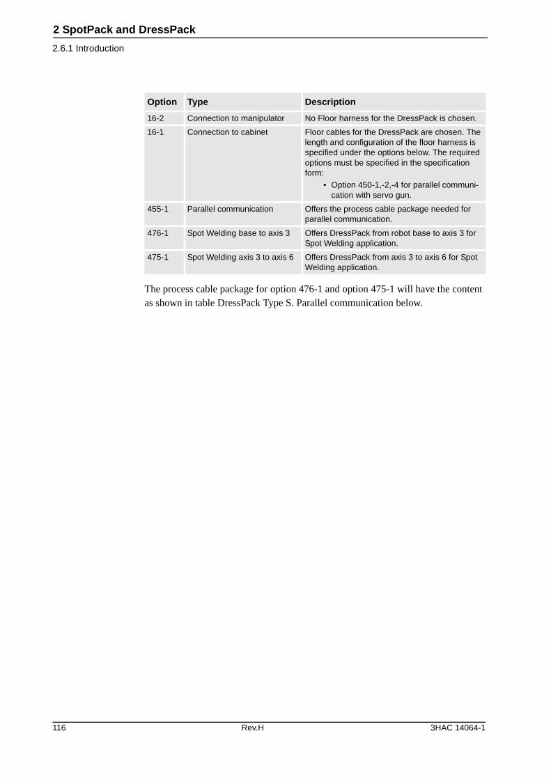
2 SpotPack and DressPack
2.6.1 Introduction
The process cable package for option 476-1 and option 475-1 will have the content as shown in table DressPack Type S. Parallel communication below.
Option Type Description
16-2 Connection to manipulator No Floor harness for the DressPack is chosen.
16-1 Connection to cabinet Floor cables for the DressPack are chosen. The length and configuration of the floor harness is specified under the options below. The required options must be specified in the specification form:
• Option 450-1,-2,-4 for parallel communi-cation with servo gun.
455-1 Parallel communication Offers the process cable package needed for parallel communication.
476-1 Spot Welding base to axis 3 Offers DressPack from robot base to axis 3 for Spot Welding application.
475-1 Spot Welding axis 3 to axis 6 Offers DressPack from axis 3 to axis 6 for Spot Welding application.
116 Rev.H 3HAC 14064-1
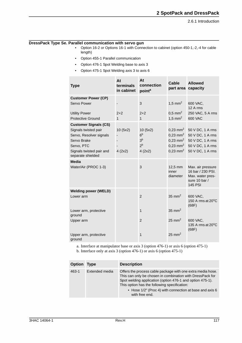
2 SpotPack and DressPack
2.6.1 Introduction
DressPack Type Se. Parallel communication with servo gun• Option 16-2 or Options 16-1 with Connection to cabinet (option 450-1,-2,-4 for cable
length)
• Option 455-1 Parallel communication
• Option 476-1 Spot Welding base to axis 3
• Option 475-1 Spot Welding axis 3 to axis 6
TypeAt terminals in cabinet
At connection pointa
a. Interface at manipulator base or axis 3 (option 476-1) or axis 6 (option 475-1)
Cable part area
Allowed capacity
Customer Power (CP)Servo Power
Utility Power
Protective Ground
-
2+2
1
3
2+2
1
1,5 mm2
0,5 mm2
1,5 mm2
600 VAC, 12 A rms
250 VAC, 5 A rms
600 VAC
Customer Signals (CS)Signals twisted pair
Servo, Resolver signals
Servo Brake
Servo, PTC
Signals twisted pair and separate shielded
10 (5x2)
-
-
-
4 (2x2)
10 (5x2)
6b
3b
2b
4 (2x2)
b. Interface only at axis 3 (option 476-1) or axis 6 (option 475-1)
0,23 mm2
0,23 mm2
0,23 mm2
0,23 mm2
0,23 mm2
50 V DC, 1 A rms
50 V DC, 1 A rms
50 V DC, 1 A rms
50 V DC, 1 A rms
50 V DC, 1 A rms
MediaWater/Air (PROC 1-3) 3 12,5 mm
inner diameter
Max. air pressure 16 bar / 230 PSI. Max. water pres-sure 10 bar / 145 PSI
Welding power (WELD)Lower arm
Lower arm, protective ground
Upper arm
Upper arm, protective ground
2
1
2
1
35 mm2
35 mm2
25 mm2
25 mm2
600 VAC, 150 A rms at 20oC (68F)
600 VAC, 135 A rms at 20oC (68F)
Option Type Description
463-1 Extended media Offers the process cable package with one extra media hose. This can only be chosen in combination with DressPack for Spot welding application (option 476-1 and option 475-1). This option has the following specification:
• Hose 1/2" (Proc 4) with connection at base and axis 6 with free end.
3HAC 14064-1 Rev.H 117
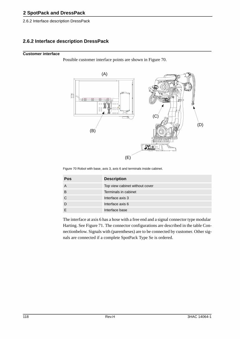
2 SpotPack and DressPack
2.6.2 Interface description DressPack
2.6.2 Interface description DressPack
Customer interfacePossible customer interface points are shown in Figure 70.
Figure 70 Robot with base, axis 3, axis 6 and terminals inside cabinet.
The interface at axis 6 has a hose with a free end and a signal connector type modular Harting. See Figure 71. The connector configurations are described in the table Con-nectionbelow. Signals with (parentheses) are to be connected by customer. Other sig-nals are connected if a complete SpotPack Type Se is ordered.
Pos Description
A Top view cabinet without cover
B Terminals in cabinet
C Interface axis 3
D Interface axis 6
E Interface base
XT6 XT5.1
(A)
(B)
(C)
(D)
(E)
118 Rev.H 3HAC 14064-1
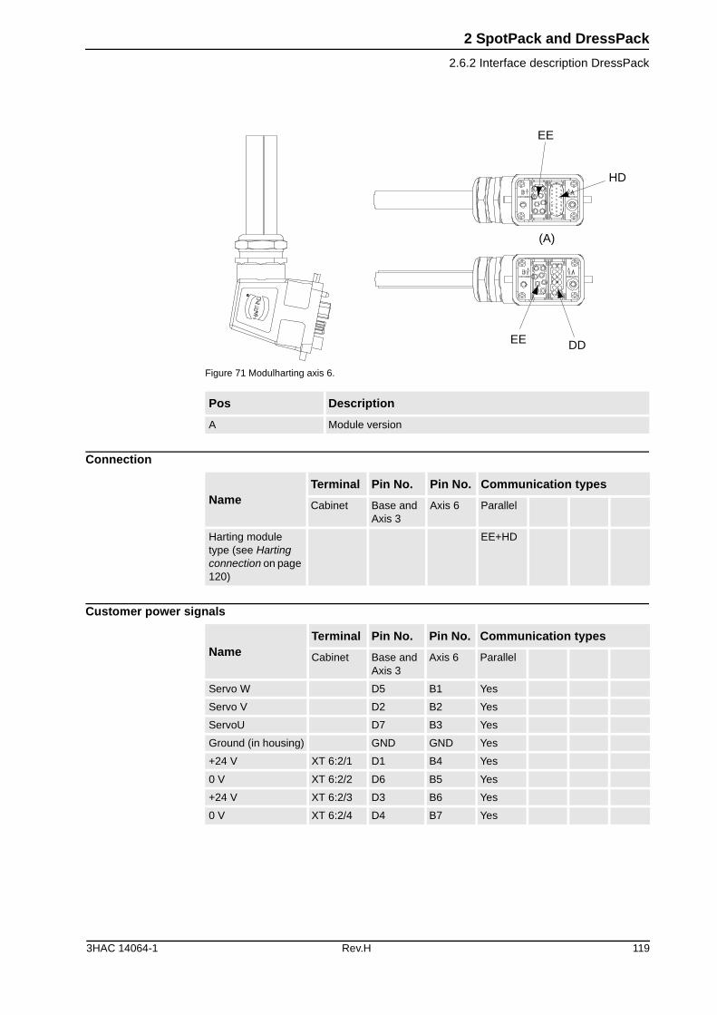
2 SpotPack and DressPack
2.6.2 Interface description DressPack
Figure 71 Modulharting axis 6.
Connection
Customer power signals
Pos Description
A Module version
EE
HD
DDEE
(A)
NameTerminal Pin No. Pin No. Communication types
Cabinet Base and Axis 3
Axis 6 Parallel
Harting module type (see Harting connection on page 120)
EE+HD
NameTerminal Pin No. Pin No. Communication types
Cabinet Base and Axis 3
Axis 6 Parallel
Servo W D5 B1 Yes
Servo V D2 B2 Yes
ServoU D7 B3 Yes
Ground (in housing) GND GND Yes
+24 V XT 6:2/1 D1 B4 Yes
0 V XT 6:2/2 D6 B5 Yes
+24 V XT 6:2/3 D3 B6 Yes
0 V XT 6:2/4 D4 B7 Yes
3HAC 14064-1 Rev.H 119
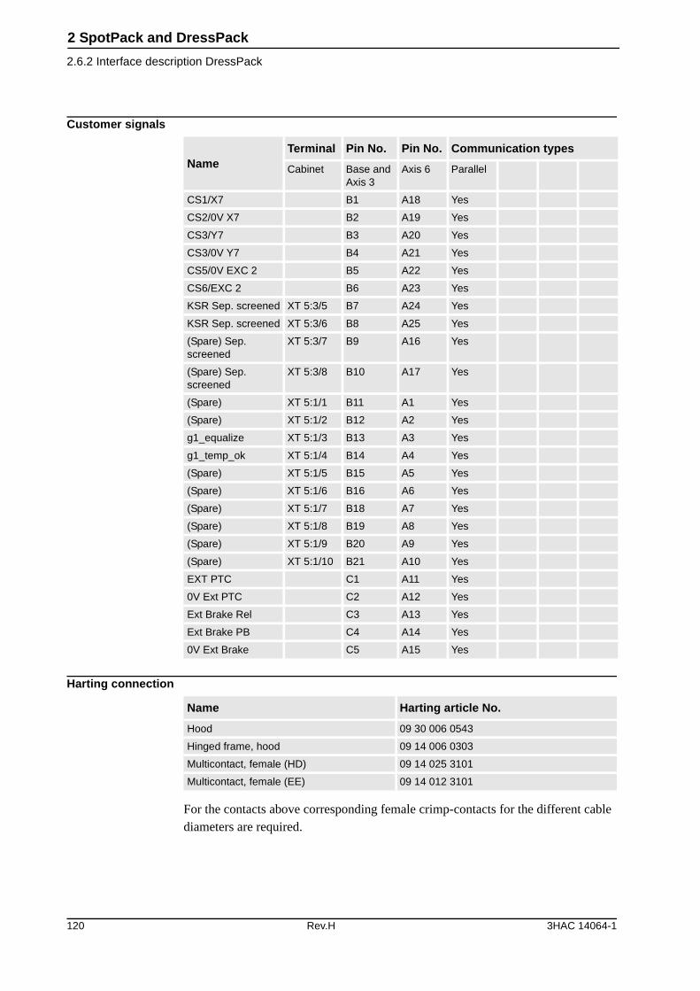
2 SpotPack and DressPack
2.6.2 Interface description DressPack
Customer signals
Harting connection
For the contacts above corresponding female crimp-contacts for the different cable diameters are required.
NameTerminal Pin No. Pin No. Communication types
Cabinet Base and Axis 3
Axis 6 Parallel
CS1/X7 B1 A18 Yes
CS2/0V X7 B2 A19 Yes
CS3/Y7 B3 A20 Yes
CS3/0V Y7 B4 A21 Yes
CS5/0V EXC 2 B5 A22 Yes
CS6/EXC 2 B6 A23 Yes
KSR Sep. screened XT 5:3/5 B7 A24 Yes
KSR Sep. screened XT 5:3/6 B8 A25 Yes
(Spare) Sep. screened
XT 5:3/7 B9 A16 Yes
(Spare) Sep. screened
XT 5:3/8 B10 A17 Yes
(Spare) XT 5:1/1 B11 A1 Yes
(Spare) XT 5:1/2 B12 A2 Yes
g1_equalize XT 5:1/3 B13 A3 Yes
g1_temp_ok XT 5:1/4 B14 A4 Yes
(Spare) XT 5:1/5 B15 A5 Yes
(Spare) XT 5:1/6 B16 A6 Yes
(Spare) XT 5:1/7 B18 A7 Yes
(Spare) XT 5:1/8 B19 A8 Yes
(Spare) XT 5:1/9 B20 A9 Yes
(Spare) XT 5:1/10 B21 A10 Yes
EXT PTC C1 A11 Yes
0V Ext PTC C2 A12 Yes
Ext Brake Rel C3 A13 Yes
Ext Brake PB C4 A14 Yes
0V Ext Brake C5 A15 Yes
Name Harting article No.
Hood 09 30 006 0543
Hinged frame, hood 09 14 006 0303
Multicontact, female (HD) 09 14 025 3101
Multicontact, female (EE) 09 14 012 3101
120 Rev.H 3HAC 14064-1
2 SpotPack and DressPack
2.6.2 Interface description DressPack
Required general options for Type Se To enable the SpotPack IRB 6600/6650/7600 to perform as intended, general stan-dard robot options are required. These standard options are further described under other chapters but are also mentioned in this chapter.
• Option 64-5 No upper cover on robot control cabinet
• Option 61-11pc. Digital 24 VDC I/O 16 inputs/ 16 outputs
• Option 191-3 Internal connection of I/O
• Option 309-3 Internal connection of safety signals
Required options for servo gunTo enable the spot welding function package SpotPack IRB 6600/6650/7600 to run with a servo controlled gun, some additional (additional to those described in previ-ous section "Required general options for Type Se") servo drive options are required. For more information see chapter 1.9 Servo Gun (option).
SpotPack Type Se with servo requires the following additional options• Option 53-2 Drive unit type DDU-V
• Option 323-1 Robot Gun
• Option 450-1,-2,-4 Connection of servo gun (7 - 30 m), see also above
• Option 341-5 SpotWare Servo (software option for servo guns)
Also, option 325-1, Servo tool change, should be added if servo gun tool change is required.
Required Power unit options for Type SeThe SpotPack IRB 6600/6650 also requires Power unit options to perform as intended. See Figure 72. These options are further described under chapter 2.8 Power Unit but are also mentioned in this chapter.
The power unit and below mentioned options are not available for S4Cplus Automotive
3HAC 14064-1 Rev.H 121
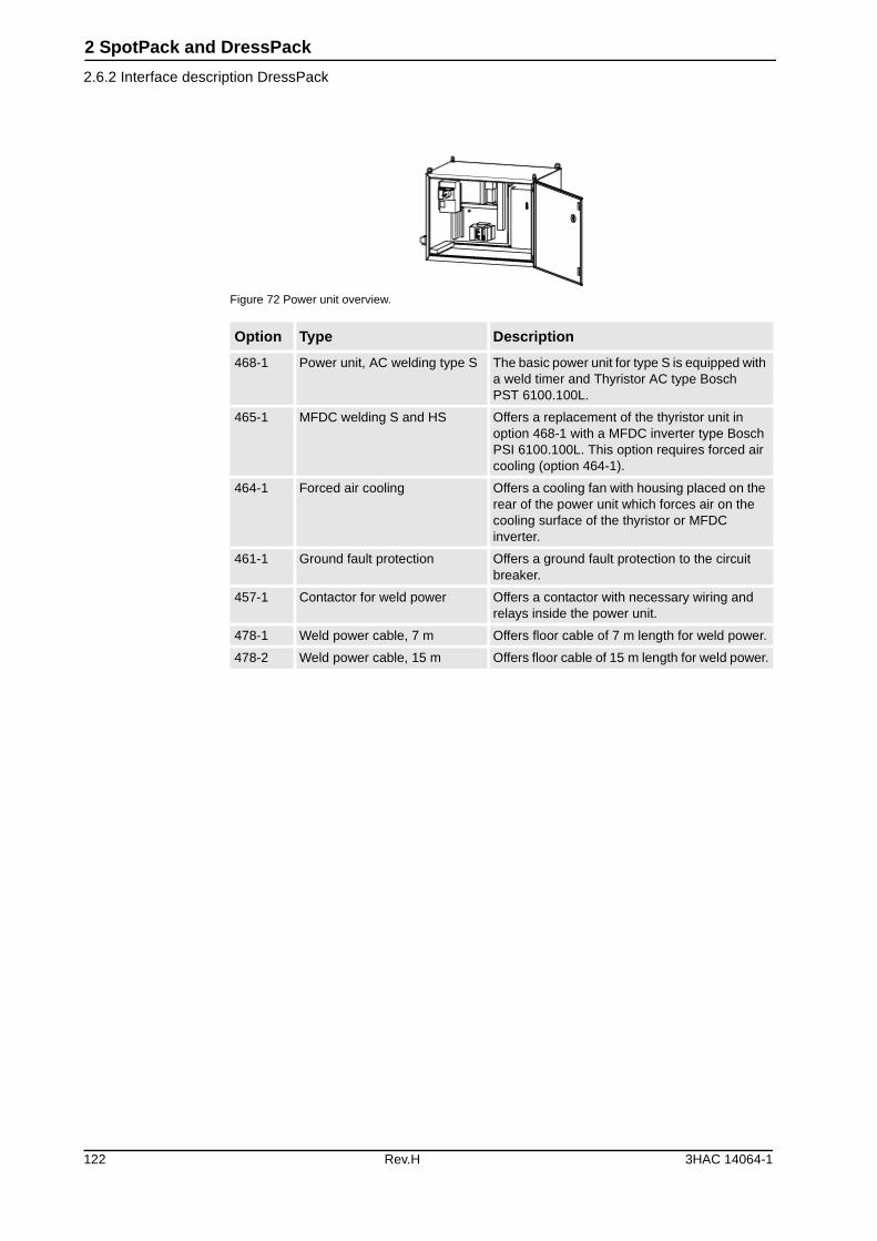
2 SpotPack and DressPack
2.6.2 Interface description DressPack
Figure 72 Power unit overview.
Option Type Description
468-1 Power unit, AC welding type S The basic power unit for type S is equipped with a weld timer and Thyristor AC type Bosch PST 6100.100L.
465-1 MFDC welding S and HS Offers a replacement of the thyristor unit in option 468-1 with a MFDC inverter type Bosch PSI 6100.100L. This option requires forced air cooling (option 464-1).
464-1 Forced air cooling Offers a cooling fan with housing placed on the rear of the power unit which forces air on the cooling surface of the thyristor or MFDC inverter.
461-1 Ground fault protection Offers a ground fault protection to the circuit breaker.
457-1 Contactor for weld power Offers a contactor with necessary wiring and relays inside the power unit.
478-1 Weld power cable, 7 m Offers floor cable of 7 m length for weld power.
478-2 Weld power cable, 15 m Offers floor cable of 15 m length for weld power.
122 Rev.H 3HAC 14064-1

2 SpotPack and DressPack
2.6.2 Interface description DressPack
Required Water and Air unit options for Type SeThe SpotPack IRB 6600/6650/7600 also requires Water and Air unit options to per-form as intended. See Figure 73. These options are further described under chapter 2.9 Water and Air Unit but are also mentioned in this chapter.
Figure 73 Water and air unit basic.
Option Type Description
477-1 Water and Air unit, type S Offers the basic water and air unit for type S including splitbox for signal distri-bution.
473-1 Second water return Offers an additional water return circuit.
460-1 Digital flow meter, One water return Offers a digital flow meter instead of a flow switch.
460-2 Digital flow meter, Two water returns Offers digital flow meter if the option sec-ond water return (option 473-1) is chosen.
469-1 Pressure switch and regulator for air Offers filter regulator and pressure switch.
454-1a
a. Not available for S4Cplus Automotive since power unit not available
Cable to split box, 7 m Offers floor cable of 7 m length for signals to the split box sitting on the water and air unit.
454-2a Cable to split box, 15 m Offers floor cable of 15 m length for sig-nals to the split box sitting on the water and air unit.
454-4 Cable to split box, 30 m Offers floor cable of 30 m length for sig-nals to the split box sitting on the water and air unit.
3HAC 14064-1 Rev.H 123
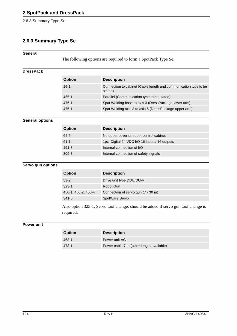
2 SpotPack and DressPack
2.6.3 Summary Type Se
2.6.3 Summary Type Se
GeneralThe following options are required to form a SpotPack Type Se.
DressPack
General options
Servo gun options
Also option 325-1, Servo tool change, should be added if servo gun tool change is required.
Power unit
Option Description
16-1 Connection to cabinet (Cable length and communication type to be stated)
455-1 Parallel (Communication type to be stated)
476-1 Spot Welding base to axis 3 (DressPackage lower arm)
475-1 Spot Welding axis 3 to axis 6 (DressPackage upper arm)
Option Description
64-5 No upper cover on robot control cabinet
61-1 1pc. Digital 24 VDC I/O 16 inputs/ 16 outputs
191-3 Internal connection of I/O
309-3 Internal connection of safety signals
Option Description
53-2 Drive unit type DDU/DU-V
323-1 Robot Gun
450-1, 450-2, 450-4 Connection of servo gun (7 - 30 m)
341-5 SpotWare Servo
Option Description
468-1 Power unit AC
478-1 Power cable 7 m (other length available)
124 Rev.H 3HAC 14064-1

2 SpotPack and DressPack
2.6.3 Summary Type Se
Water and air unit
Other described options depend on specific system need and performance.
Option Description
477-1 Water and air unit
454-1 Splitbox cable 7 m. (other length available)
The power unit and the water and air unit are not available for S4Cplus Automotive
3HAC 14064-1 Rev.H 125
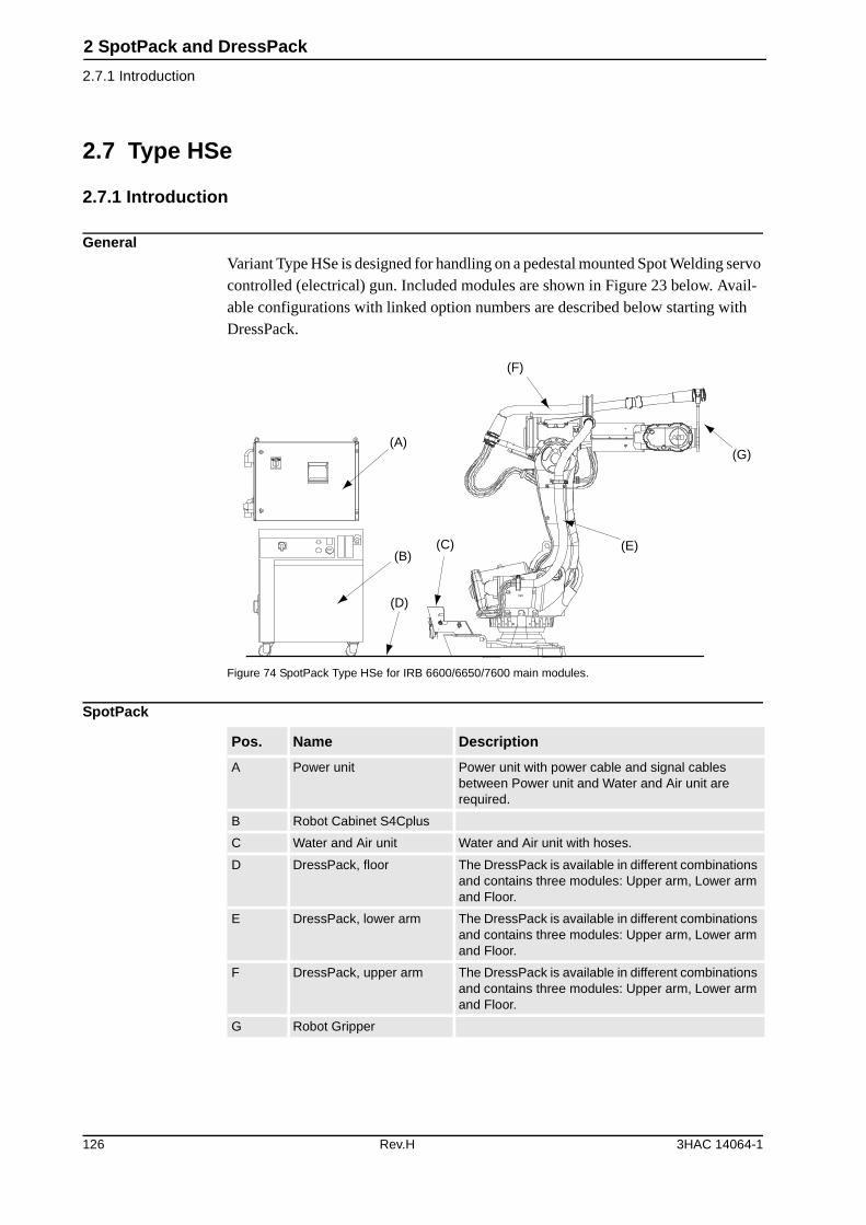
2 SpotPack and DressPack
2.7.1 Introduction
2.7 Type HSe
2.7.1 Introduction
GeneralVariant Type HSe is designed for handling on a pedestal mounted Spot Welding servo controlled (electrical) gun. Included modules are shown in Figure 23 below. Avail-able configurations with linked option numbers are described below starting with DressPack.
Figure 74 SpotPack Type HSe for IRB 6600/6650/7600 main modules.
SpotPack
(A)
(B)(C)
(D)
(F)
(E)
(G)
Pos. Name Description
A Power unit Power unit with power cable and signal cables between Power unit and Water and Air unit are required.
B Robot Cabinet S4Cplus
C Water and Air unit Water and Air unit with hoses.
D DressPack, floor The DressPack is available in different combinations and contains three modules: Upper arm, Lower arm and Floor.
E DressPack, lower arm The DressPack is available in different combinations and contains three modules: Upper arm, Lower arm and Floor.
F DressPack, upper arm The DressPack is available in different combinations and contains three modules: Upper arm, Lower arm and Floor.
G Robot Gripper
126 Rev.H 3HAC 14064-1
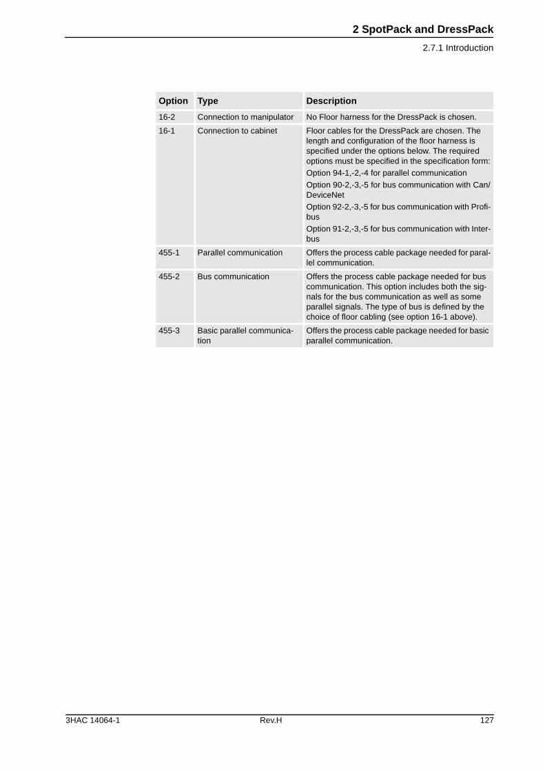
2 SpotPack and DressPack
2.7.1 Introduction
Option Type Description
16-2 Connection to manipulator No Floor harness for the DressPack is chosen.
16-1 Connection to cabinet Floor cables for the DressPack are chosen. The length and configuration of the floor harness is specified under the options below. The required options must be specified in the specification form:
Option 94-1,-2,-4 for parallel communication
Option 90-2,-3,-5 for bus communication with Can/DeviceNet
Option 92-2,-3,-5 for bus communication with Profi-bus
Option 91-2,-3,-5 for bus communication with Inter-bus
455-1 Parallel communication Offers the process cable package needed for paral-lel communication.
455-2 Bus communication Offers the process cable package needed for bus communication. This option includes both the sig-nals for the bus communication as well as some parallel signals. The type of bus is defined by the choice of floor cabling (see option 16-1 above).
455-3 Basic parallel communica-tion
Offers the process cable package needed for basic parallel communication.
3HAC 14064-1 Rev.H 127
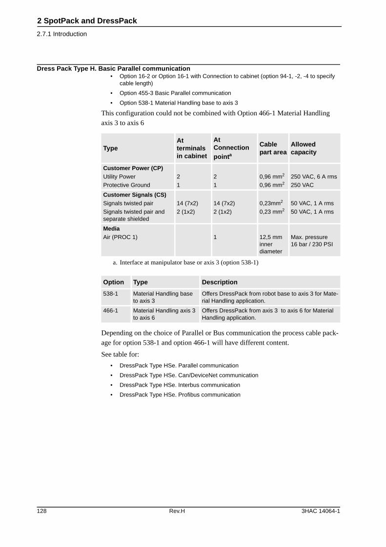
2 SpotPack and DressPack
2.7.1 Introduction
Dress Pack Type H. Basic Parallel communication• Option 16-2 or Option 16-1 with Connection to cabinet (option 94-1, -2, -4 to specify
cable length)
• Option 455-3 Basic Parallel communication
• Option 538-1 Material Handling base to axis 3
This configuration could not be combined with Option 466-1 Material Handling axis 3 to axis 6
Depending on the choice of Parallel or Bus communication the process cable pack-age for option 538-1 and option 466-1 will have different content.
See table for:
• DressPack Type HSe. Parallel communication
• DressPack Type HSe. Can/DeviceNet communication
• DressPack Type HSe. Interbus communication
• DressPack Type HSe. Profibus communication
TypeAt terminals in cabinet
At Connection pointa
a. Interface at manipulator base or axis 3 (option 538-1)
Cable part area
Allowed capacity
Customer Power (CP)Utility Power
Protective Ground
2
1
2
1
0,96 mm2
0,96 mm2
250 VAC, 6 A rms
250 VAC
Customer Signals (CS)Signals twisted pair
Signals twisted pair and separate shielded
14 (7x2)
2 (1x2)
14 (7x2)
2 (1x2)
0,23mm2
0,23 mm2
50 VAC, 1 A rms
50 VAC, 1 A rms
MediaAir (PROC 1) 1 12,5 mm
inner diameter
Max. pressure 16 bar / 230 PSI
Option Type Description
538-1 Material Handling base to axis 3
Offers DressPack from robot base to axis 3 for Mate-rial Handling application.
466-1 Material Handling axis 3 to axis 6
Offers DressPack from axis 3 to axis 6 for Material Handling application.
128 Rev.H 3HAC 14064-1
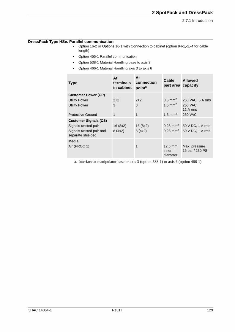
2 SpotPack and DressPack
2.7.1 Introduction
DressPack Type HSe. Parallel communication• Option 16-2 or Options 16-1 with Connection to cabinet (option 94-1,-2,-4 for cable
length)
• Option 455-1 Parallel communication
• Option 538-1 Material Handling base to axis 3
• Option 466-1 Material Handling axis 3 to axis 6
TypeAt terminals in cabinet
At connection pointa
a. Interface at manipulator base or axis 3 (option 538-1) or axis 6 (option 466-1)
Cable part area
Allowed capacity
Customer Power (CP)Utility Power
Utility Power
Protective Ground
2+2
3
1
2+2
3
1
0,5 mm2
1,5 mm2
1,5 mm2
250 VAC, 5 A rms
250 VAC, 12 A rms
250 VAC
Customer Signals (CS)Signals twisted pair
Signals twisted pair and separate shielded
16 (8x2)
8 (4x2)
16 (8x2)
8 (4x2)
0,23 mm2
0,23 mm2
50 V DC, 1 A rms
50 V DC, 1 A rms
MediaAir (PROC 1) 1 12,5 mm
inner diameter
Max. pressure 16 bar / 230 PSI
3HAC 14064-1 Rev.H 129
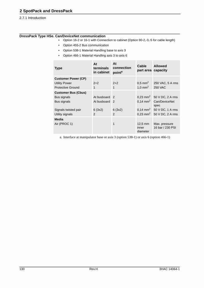
2 SpotPack and DressPack
2.7.1 Introduction
DressPack Type HSe. Can/DeviceNet communication• Option 16-2 or 16-1 with Connection to cabinet (Option 90-2,-3,-5 for cable length)
• Option 455-2 Bus communication
• Option 538-1 Material Handling base to axis 3
• Option 466-1 Material Handling axis 3 to axis 6
TypeAt terminals in cabinet
At connection pointa
a. Interface at manipulator base or axis 3 (option 538-1) or axis 6 (option 466-1)
Cable part area
Allowed capacity
Customer Power (CP)Utility Power
Protective Ground
2+2
1
2+2
1
0,5 mm2
1,0 mm2
250 VAC, 5 A rms
250 VAC
Customer Bus (Cbus)Bus signals
Bus signals
Signals twisted pair
Utility signals
At busboard
At busboard
6 (3x2)
2
2
2
6 (3x2)
2
0,23 mm2
0,14 mm2
0,14 mm2
0,23 mm2
50 V DC, 2 A rms
Can/DeviceNet spec
50 V DC, 1 A rms
50 V DC, 2 A rms
MediaAir (PROC 1) 1 12,5 mm
inner diameter
Max. pressure 16 bar / 230 PSI
130 Rev.H 3HAC 14064-1

2 SpotPack and DressPack
2.7.1 Introduction
DressPack Type HSe. Interbus communication• Option 16-2 or Options 16-1 with Connection to cabinet (Option 91-2,-3,-5 for cable
length)
• Option 455-2 Bus communication
• Option 538-1 Material Handling base to axis 3
• Option 466-1 Material Handling axis 3 to axis 6
TypeAt terminals in cabinet
At connection pointa
a. Interface at manipulator base or axis 3 (option 538-1) or axis 6 (option 466-1)
Cable part area
Allowed capacity
Customer Power (CP)Utility Power
Protective Ground
2+2
1
2+2
1
0,5 mm2
1,0 mm2
250 VAC, 5 A rms
250 VAC
Customer Bus (Cbus)Bus signals
Bus signals
Signals twisted pair
Utility signals
At busboard
At busboard
4 (2x2)
3
1
4
4 (2x2)
3
0,23 mm2
0,14 mm2
0,14 mm2
0,23 mm2
50 V DC, 2 A rms
Can/DeviceNet spec
50 V DC, 1 A rms
50 V DC, 2 A rms
MediaAir (PROC 1) 1 12,5 mm
inner diameter
Max. pressure 16 bar / 230 PSI
3HAC 14064-1 Rev.H 131
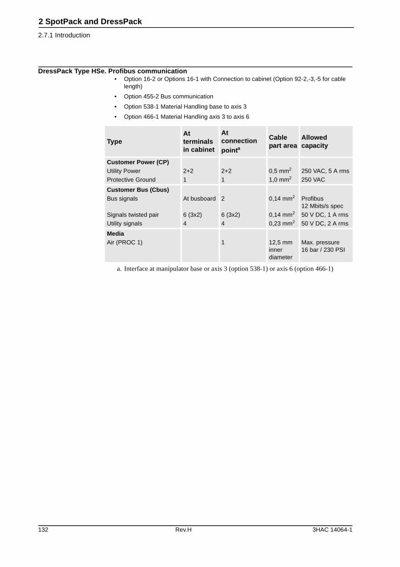
2 SpotPack and DressPack
2.7.1 Introduction
DressPack Type HSe. Profibus communication• Option 16-2 or Options 16-1 with Connection to cabinet (Option 92-2,-3,-5 for cable
length)
• Option 455-2 Bus communication
• Option 538-1 Material Handling base to axis 3
• Option 466-1 Material Handling axis 3 to axis 6
TypeAt terminals in cabinet
At connection pointa
a. Interface at manipulator base or axis 3 (option 538-1) or axis 6 (option 466-1)
Cable part area
Allowed capacity
Customer Power (CP)Utility Power
Protective Ground
2+2
1
2+2
1
0,5 mm2
1,0 mm2
250 VAC, 5 A rms
250 VAC
Customer Bus (Cbus)Bus signals
Signals twisted pair
Utility signals
At busboard
6 (3x2)
4
2
6 (3x2)
4
0,14 mm2
0,14 mm2
0,23 mm2
Profibus12 Mbits/s spec
50 V DC, 1 A rms
50 V DC, 2 A rms
MediaAir (PROC 1) 1 12,5 mm
inner diameter
Max. pressure 16 bar / 230 PSI
132 Rev.H 3HAC 14064-1
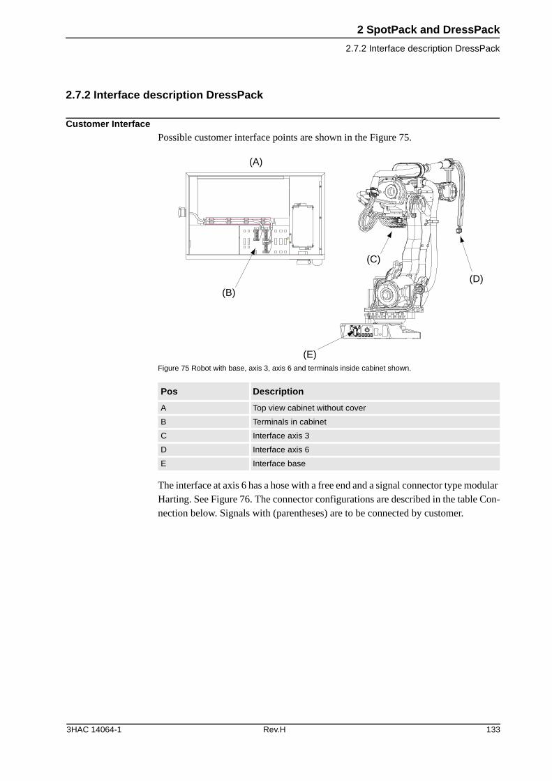
2 SpotPack and DressPack
2.7.2 Interface description DressPack
2.7.2 Interface description DressPack
Customer InterfacePossible customer interface points are shown in the Figure 75.
Figure 75 Robot with base, axis 3, axis 6 and terminals inside cabinet shown.
The interface at axis 6 has a hose with a free end and a signal connector type modular Harting. See Figure 76. The connector configurations are described in the table Con-nection below. Signals with (parentheses) are to be connected by customer.
Pos Description
A Top view cabinet without cover
B Terminals in cabinet
C Interface axis 3
D Interface axis 6
E Interface base
XT6 XT5.1
(A)
(B)
(C)
(D)
(E)
3HAC 14064-1 Rev.H 133
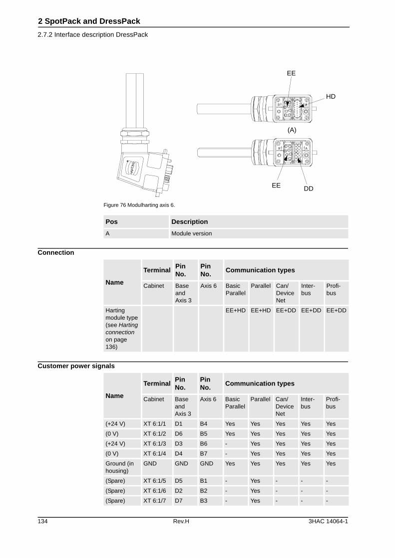
2 SpotPack and DressPack
2.7.2 Interface description DressPack
Figure 76 Modulharting axis 6.
Connection
Customer power signals
Pos Description
A Module version
EE
HD
DDEE
(A)
Name
TerminalPin No.
Pin No.
Communication types
Cabinet Base and Axis 3
Axis 6 Basic Parallel
Parallel Can/ DeviceNet
Inter-bus
Profi-bus
Harting module type (see Harting connection on page 136)
EE+HD EE+HD EE+DD EE+DD EE+DD
Name
TerminalPin No.
Pin No.
Communication types
Cabinet Base and Axis 3
Axis 6 Basic Parallel
Parallel Can/ DeviceNet
Inter-bus
Profi-bus
(+24 V) XT 6:1/1 D1 B4 Yes Yes Yes Yes Yes
(0 V) XT 6:1/2 D6 B5 Yes Yes Yes Yes Yes
(+24 V) XT 6:1/3 D3 B6 - Yes Yes Yes Yes
(0 V) XT 6:1/4 D4 B7 - Yes Yes Yes Yes
Ground (in housing)
GND GND GND Yes Yes Yes Yes Yes
(Spare) XT 6:1/5 D5 B1 - Yes - - -
(Spare) XT 6:1/6 D2 B2 - Yes - - -
(Spare) XT 6:1/7 D7 B3 - Yes - - -
134 Rev.H 3HAC 14064-1
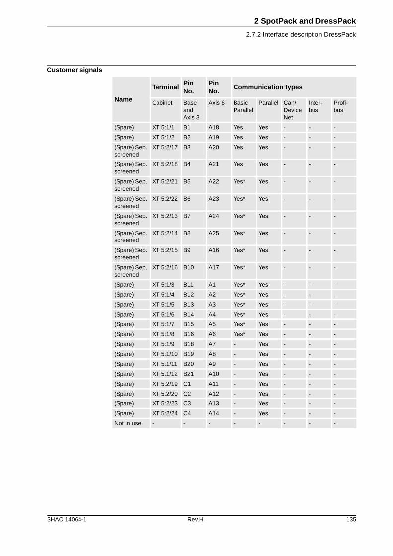
2 SpotPack and DressPack
2.7.2 Interface description DressPack
Customer signals
Name
TerminalPin No.
Pin No.
Communication types
Cabinet Base and Axis 3
Axis 6 Basic Parallel
Parallel Can/ DeviceNet
Inter-bus
Profi-bus
(Spare) XT 5:1/1 B1 A18 Yes Yes - - -
(Spare) XT 5:1/2 B2 A19 Yes Yes - - -
(Spare) Sep. screened
XT 5:2/17 B3 A20 Yes Yes - - -
(Spare) Sep. screened
XT 5:2/18 B4 A21 Yes Yes - - -
(Spare) Sep. screened
XT 5:2/21 B5 A22 Yes* Yes - - -
(Spare) Sep. screened
XT 5:2/22 B6 A23 Yes* Yes - - -
(Spare) Sep. screened
XT 5:2/13 B7 A24 Yes* Yes - - -
(Spare) Sep. screened
XT 5:2/14 B8 A25 Yes* Yes - - -
(Spare) Sep. screened
XT 5:2/15 B9 A16 Yes* Yes - - -
(Spare) Sep. screened
XT 5:2/16 B10 A17 Yes* Yes - - -
(Spare) XT 5:1/3 B11 A1 Yes* Yes - - -
(Spare) XT 5:1/4 B12 A2 Yes* Yes - - -
(Spare) XT 5:1/5 B13 A3 Yes* Yes - - -
(Spare) XT 5:1/6 B14 A4 Yes* Yes - - -
(Spare) XT 5:1/7 B15 A5 Yes* Yes - - -
(Spare) XT 5:1/8 B16 A6 Yes* Yes - - -
(Spare) XT 5:1/9 B18 A7 - Yes - - -
(Spare) XT 5:1/10 B19 A8 - Yes - - -
(Spare) XT 5:1/11 B20 A9 - Yes - - -
(Spare) XT 5:1/12 B21 A10 - Yes - - -
(Spare) XT 5:2/19 C1 A11 - Yes - - -
(Spare) XT 5:2/20 C2 A12 - Yes - - -
(Spare) XT 5:2/23 C3 A13 - Yes - - -
(Spare) XT 5:2/24 C4 A14 - Yes - - -
Not in use - - - - - - - -
3HAC 14064-1 Rev.H 135
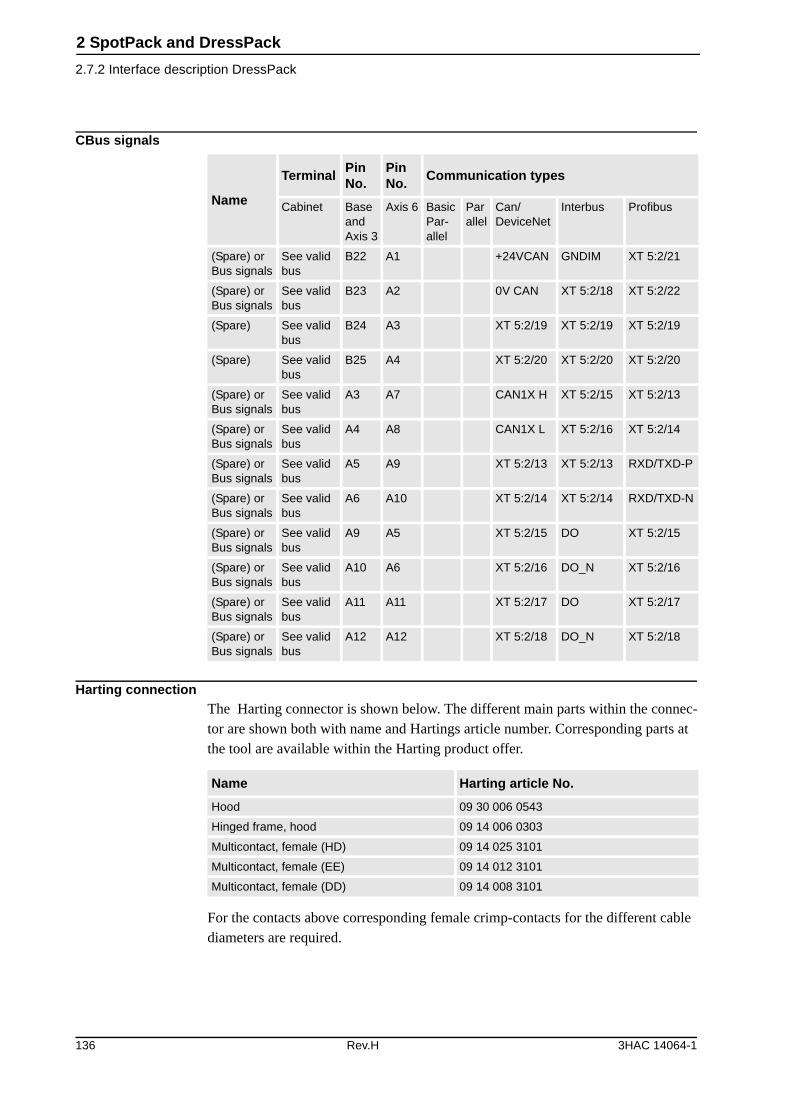
2 SpotPack and DressPack
2.7.2 Interface description DressPack
CBus signals
Harting connectionThe Harting connector is shown below. The different main parts within the connec-tor are shown both with name and Hartings article number. Corresponding parts at the tool are available within the Harting product offer.
For the contacts above corresponding female crimp-contacts for the different cable diameters are required.
Name
TerminalPin No.
Pin No.
Communication types
Cabinet Base and Axis 3
Axis 6 Basic Par-allel
Parallel
Can/ DeviceNet
Interbus Profibus
(Spare) or Bus signals
See valid bus
B22 A1 +24VCAN GNDIM XT 5:2/21
(Spare) or Bus signals
See valid bus
B23 A2 0V CAN XT 5:2/18 XT 5:2/22
(Spare) See valid bus
B24 A3 XT 5:2/19 XT 5:2/19 XT 5:2/19
(Spare) See valid bus
B25 A4 XT 5:2/20 XT 5:2/20 XT 5:2/20
(Spare) or Bus signals
See valid bus
A3 A7 CAN1X H XT 5:2/15 XT 5:2/13
(Spare) or Bus signals
See valid bus
A4 A8 CAN1X L XT 5:2/16 XT 5:2/14
(Spare) or Bus signals
See valid bus
A5 A9 XT 5:2/13 XT 5:2/13 RXD/TXD-P
(Spare) or Bus signals
See valid bus
A6 A10 XT 5:2/14 XT 5:2/14 RXD/TXD-N
(Spare) or Bus signals
See valid bus
A9 A5 XT 5:2/15 DO XT 5:2/15
(Spare) or Bus signals
See valid bus
A10 A6 XT 5:2/16 DO_N XT 5:2/16
(Spare) or Bus signals
See valid bus
A11 A11 XT 5:2/17 DO XT 5:2/17
(Spare) or Bus signals
See valid bus
A12 A12 XT 5:2/18 DO_N XT 5:2/18
Name Harting article No.
Hood 09 30 006 0543
Hinged frame, hood 09 14 006 0303
Multicontact, female (HD) 09 14 025 3101
Multicontact, female (EE) 09 14 012 3101
Multicontact, female (DD) 09 14 008 3101
136 Rev.H 3HAC 14064-1
2 SpotPack and DressPack
2.7.2 Interface description DressPack
Required general options for Type HSeTo enable the SpotPack IRB 6600/6650/7600 to perform as intended, general stan-dard robot options are required. These standard options are further described under other chapters but are also mentioned in this chapter.
SpotPack Type HSe standard requires following general robot options• Option 64-5 No upper cover on robot control cabinet
• Option 61-1 1pc. Digital 24 VDC I/O 16 inputs/ 16 outputs
• Option 191-3 Internal connection of I/O
• Option 309-3 Internal connection of safety signals
Servo gun options• Option 53-2 Drive unit type DDU-V
• Option 323-5 Stationary Gun
• Option 95-1,-2,-4 Connection of servo gun (7 - 30 m)
• Option 341-5 SpotWare Servo (software option for servo guns)
Required Power unit options for Type HSeThe SpotPack IRB 6600/6650/7600 also requires Power unit options to perform as intended. See Figure 77. These options are further described under chapter 2.8 Power Unit but are also mentioned in this chapter.
The power unit and below mentioned options are not available for S4Cplus Automotive
3HAC 14064-1 Rev.H 137
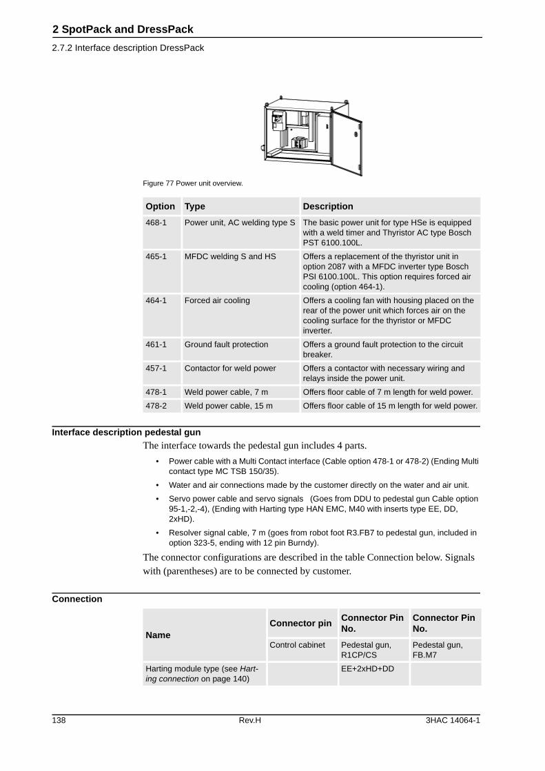
2 SpotPack and DressPack
2.7.2 Interface description DressPack
Figure 77 Power unit overview.
Interface description pedestal gunThe interface towards the pedestal gun includes 4 parts.
• Power cable with a Multi Contact interface (Cable option 478-1 or 478-2) (Ending Multi contact type MC TSB 150/35).
• Water and air connections made by the customer directly on the water and air unit.
• Servo power cable and servo signals (Goes from DDU to pedestal gun Cable option 95-1,-2,-4), (Ending with Harting type HAN EMC, M40 with inserts type EE, DD, 2xHD).
• Resolver signal cable, 7 m (goes from robot foot R3.FB7 to pedestal gun, included in option 323-5, ending with 12 pin Burndy).
The connector configurations are described in the table Connection below. Signals with (parentheses) are to be connected by customer.
Connection
Option Type Description
468-1 Power unit, AC welding type S The basic power unit for type HSe is equipped with a weld timer and Thyristor AC type Bosch PST 6100.100L.
465-1 MFDC welding S and HS Offers a replacement of the thyristor unit in option 2087 with a MFDC inverter type Bosch PSI 6100.100L. This option requires forced air cooling (option 464-1).
464-1 Forced air cooling Offers a cooling fan with housing placed on the rear of the power unit which forces air on the cooling surface for the thyristor or MFDC inverter.
461-1 Ground fault protection Offers a ground fault protection to the circuit breaker.
457-1 Contactor for weld power Offers a contactor with necessary wiring and relays inside the power unit.
478-1 Weld power cable, 7 m Offers floor cable of 7 m length for weld power.
478-2 Weld power cable, 15 m Offers floor cable of 15 m length for weld power.
NameConnector pin
Connector Pin No.
Connector Pin No.
Control cabinet Pedestal gun, R1CP/CS
Pedestal gun, FB.M7
Harting module type (see Hart-ing connection on page 140)
EE+2xHD+DD
138 Rev.H 3HAC 14064-1
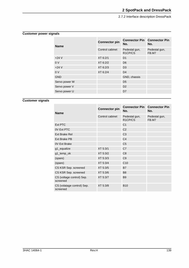
2 SpotPack and DressPack
2.7.2 Interface description DressPack
Customer power signals
Customer signals
NameConnector pin
Connector Pin No.
Connector Pin No.
Control cabinet Pedestal gun, R1CP/CS
Pedestal gun, FB.M7
+24 V XT 6:2/1 D1
0 V XT 6:2/2 D6
+24 V XT 6:2/3 D3
0 V XT 6:2/4 D4
GND GND, chassis
Servo power W D5
Servo power V D2
Servo power U D7
NameConnector pin
Connector Pin No.
Connector Pin No.
Control cabinet Pedestal gun, R1CP/CS
Pedestal gun, FB.M7
Ext PTC C1
0V Ext PTC C2
Ext Brake Rel C3
Ext Brake PB C4
0V Ext Brake C5
g1_equalize XT 5:3/1 C7
g1_temp_ok XT 5:3/2 C8
(spare) XT 5:3/3 C9
(spare) XT 5:3/4 C10
CS KSR Sep. screened XT 5:3/5 B7
CS KSR Sep. screened XT 5:3/6 B8
CS (voltage control) Sep. screened
XT 5:3/7 B9
CS (volatage control) Sep. screened
XT 5:3/8 B10
3HAC 14064-1 Rev.H 139
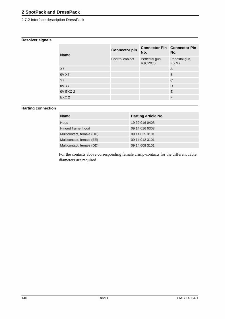
2 SpotPack and DressPack
2.7.2 Interface description DressPack
Resolver signals
Harting connection
For the contacts above corresponding female crimp-contacts for the different cable diameters are required.
NameConnector pin
Connector Pin No.
Connector Pin No.
Control cabinet Pedestal gun, R1CP/CS
Pedestal gun, FB.M7
X7 A
0V X7 B
Y7 C
0V Y7 D
0V EXC 2 E
EXC 2 F
Name Harting article No.
Hood 19 39 016 0408
Hinged frame, hood 09 14 016 0303
Multicontact, female (HD) 09 14 025 3101
Multicontact, female (EE) 09 14 012 3101
Multicontact, female (DD) 09 14 008 3101
140 Rev.H 3HAC 14064-1
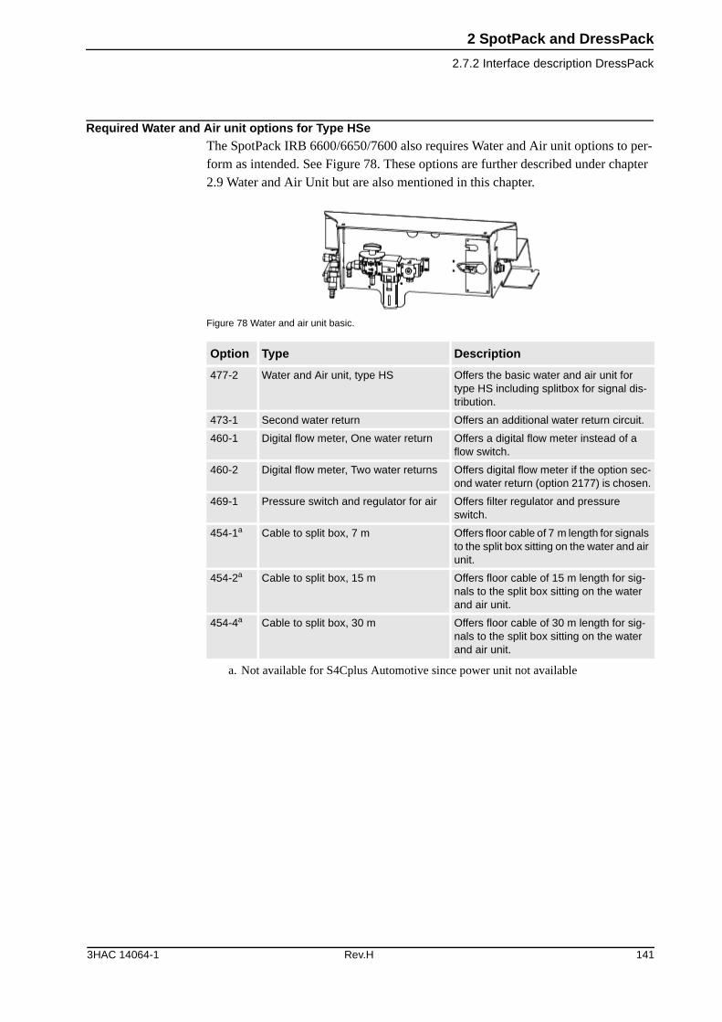
2 SpotPack and DressPack
2.7.2 Interface description DressPack
Required Water and Air unit options for Type HSe The SpotPack IRB 6600/6650/7600 also requires Water and Air unit options to per-form as intended. See Figure 78. These options are further described under chapter 2.9 Water and Air Unit but are also mentioned in this chapter.
Figure 78 Water and air unit basic.
Option Type Description
477-2 Water and Air unit, type HS Offers the basic water and air unit for type HS including splitbox for signal dis-tribution.
473-1 Second water return Offers an additional water return circuit.
460-1 Digital flow meter, One water return Offers a digital flow meter instead of a flow switch.
460-2 Digital flow meter, Two water returns Offers digital flow meter if the option sec-ond water return (option 2177) is chosen.
469-1 Pressure switch and regulator for air Offers filter regulator and pressure switch.
454-1a
a. Not available for S4Cplus Automotive since power unit not available
Cable to split box, 7 m Offers floor cable of 7 m length for signals to the split box sitting on the water and air unit.
454-2a Cable to split box, 15 m Offers floor cable of 15 m length for sig-nals to the split box sitting on the water and air unit.
454-4a Cable to split box, 30 m Offers floor cable of 30 m length for sig-nals to the split box sitting on the water and air unit.
3HAC 14064-1 Rev.H 141
2 SpotPack and DressPack
2.7.3 Summary Type HSe
2.7.3 Summary Type HSe
GeneralThe following options are required to form a SpotPack Type HSe:
DressPack
General options
Servo gun options
Power unit
Water and air unit
Other described options depends on specific system need and performance.
Option Description
16-1 Connection to cabinet (Cable length and communication type to be stated).
455-1,455-2, 455-3 Parallel, Basic Parallel or Bus communication (Communication type to be stated)
538-1 Material Handling base to axis 3 (DressPackage lower arm)
466-1 Material Handling axis 3 to axis 6 (DressPackage upper arm)
Option Description
64-5 No upper cover on robot control cabinet
61-1 1pc. Digital 24 VDC I/O 16 inputs/ 16 outputs.
191-3 Internal connection of I/O
309-3 Internal connection of safety signals
Option Description
53-2 Drive unit type DDU/DU-V
323-5 Stationary Gun.
95-1,-2,-4 Connection of servo gun (7 - 30 m)
341-5 SpotWare Servo
Option Description
468-2 Power unit AC type HS
478-1 Power cable 7 m (other length available)
The power unit is not available for S4Cplus Automotive.
Option Description
477-2 Water and air unit type HS
454-1a
a. Not available for S4Cplus Automotive
Splitbox cable 7 m. (other length available)
142 Rev.H 3HAC 14064-1
2 SpotPack and DressPack
2.8.1 Introduction
2.8 Power Unit
2.8.1 Introduction
GeneralThe Power unit for SpotPack contains the electric components and circuits needed for Spot Welding application. The Power unit, with the welding controller built in, is via the process software controlled from the robot controller.
The capacity and functionality depends on the choice of different option combina-tions.
CabinetThe power unit cabinet is designed to be placed on top of the robot controller cabinet, see Figure 79. All cables are connected on the left hand side of the power unit.
The Power unit has the following main features.
• Adjustable thermal release and short circuit release.
• Cross connection of signal handling with fusing for selectivity.
• Programmable weld timer with KSR regulation and proportional valve control.
• Preparation for additional options and preparation for easy exchange.
Figure 79 Power unit from different view incl. dimensions and connections (dimensions in mm).
The electrical circuits of the power unit consist of weld power circuit and control circuits to control the welding.
The power unit is not available for S4Cplus Automotive
800
800
950
650
115530
500
62371 52
3HAC 14064-1 Rev.H 143
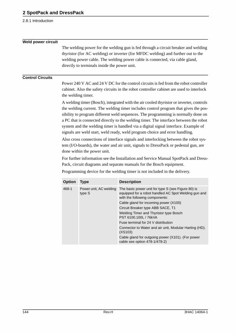
2 SpotPack and DressPack
2.8.1 Introduction
Weld power circuitThe welding power for the welding gun is fed through a circuit breaker and welding thyristor (for AC welding) or inverter (for MFDC welding) and further out to the welding power cable. The welding power cable is connected, via cable gland, directly to terminals inside the power unit.
Control CircuitsPower 240 V AC and 24 V DC for the control circuits is fed from the robot controller cabinet. Also the safety circuits in the robot controller cabinet are used to interlock the welding timer.
A welding timer (Bosch), integrated with the air cooled thyristor or inverter, controls the welding current. The welding timer includes control program that gives the pos-sibility to program different weld sequences. The programming is normally done on a PC that is connected directly to the welding timer. The interface between the robot system and the welding timer is handled via a digital signal interface. Example of signals are weld start, weld ready, weld program choice and error handling.
Also cross connections of interface signals and interlocking between the robot sys-tem (I/O-boards), the water and air unit, signals to DressPack or pedestal gun, are done within the power unit.
For further information see the Installation and Service Manual SpotPack and Dress-Pack, circuit diagrams and separate manuals for the Bosch equipment.
Programming device for the welding timer is not included in the delivery.
Option Type Description
468-1 Power unit, AC welding type S
The basic power unit for type S (see Figure 80) is equipped for a robot handled AC Spot Welding gun and with the following components:
Cable gland for incoming power (X100)
Circuit Breaker type ABB SACE, T1
Welding Timer and Thyristor type BoschPST 6100.100L / 76kVA
Fuse terminal for 24 V distribution
Connector to Water and air unit, Modular Harting (HD). (XS103)
Cable gland for outgoing power (X101). (For power cable see option 478-1/478-2)
144 Rev.H 3HAC 14064-1
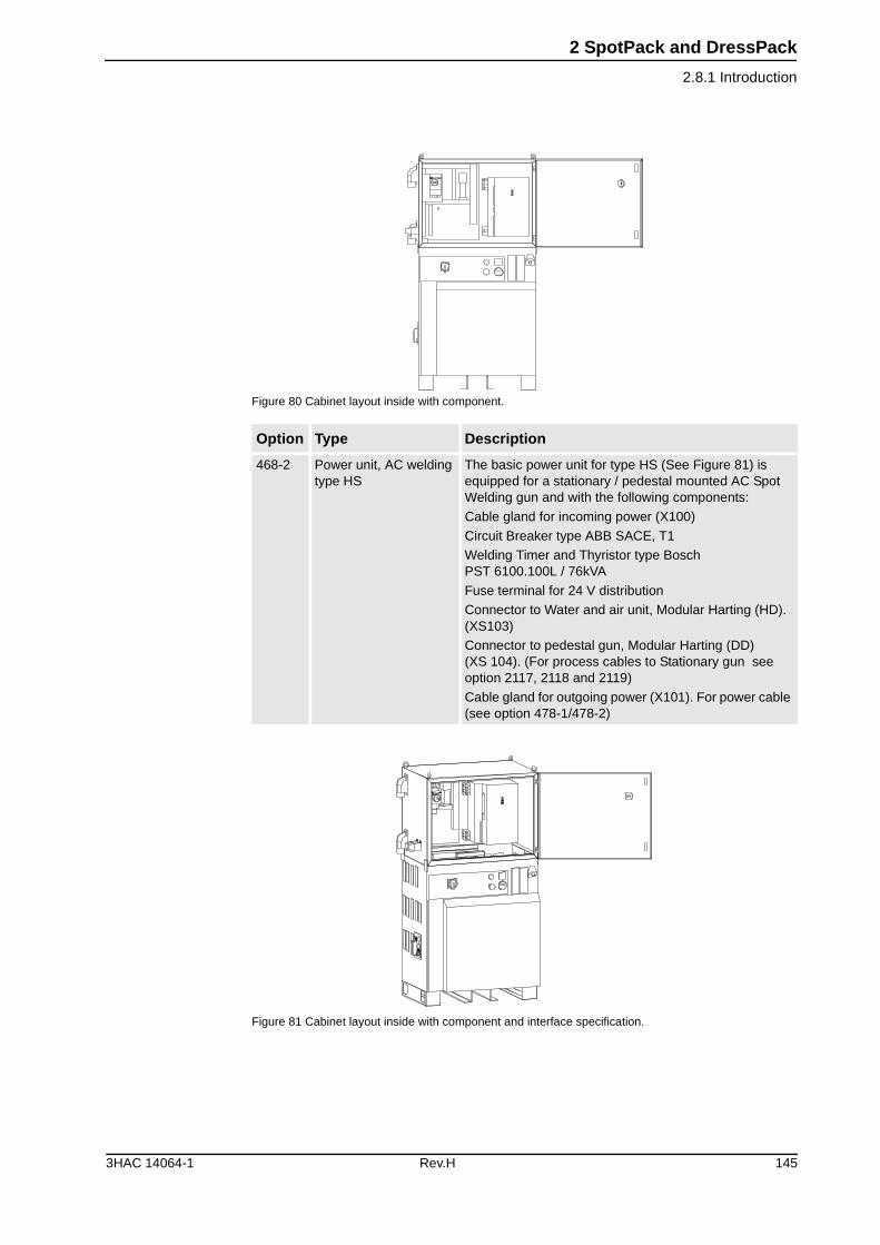
2 SpotPack and DressPack
2.8.1 Introduction
Figure 80 Cabinet layout inside with component.
Figure 81 Cabinet layout inside with component and interface specification.
Option Type Description
468-2 Power unit, AC welding type HS
The basic power unit for type HS (See Figure 81) is equipped for a stationary / pedestal mounted AC Spot Welding gun and with the following components:
Cable gland for incoming power (X100)
Circuit Breaker type ABB SACE, T1
Welding Timer and Thyristor type BoschPST 6100.100L / 76kVA
Fuse terminal for 24 V distribution
Connector to Water and air unit, Modular Harting (HD). (XS103)
Connector to pedestal gun, Modular Harting (DD)(XS 104). (For process cables to Stationary gun see option 2117, 2118 and 2119)
Cable gland for outgoing power (X101). For power cable (see option 478-1/478-2)
3HAC 14064-1 Rev.H 145
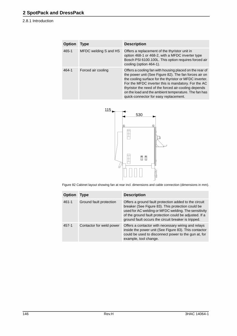
2 SpotPack and DressPack
2.8.1 Introduction
Figure 82 Cabinet layout showing fan at rear incl. dimensions and cable connection (dimensions in mm).
Option Type Description
465-1 MFDC welding S and HS Offers a replacement of the thyristor unit in option 468-1 or 468-2, with a MFDC inverter type Bosch PSI 6100.100L. This option requires forced air cooling (option 464-1).
464-1 Forced air cooling Offers a cooling fan with housing placed on the rear of the power unit (See Figure 82). The fan forces air on the cooling surface for the thyristor or MFDC inverter. For the MFDC inverter this is mandatory. For the AC thyristor the need of the forced air-cooling depends on the load and the ambient temperature. The fan has quick-connector for easy replacement.
Option Type Description
461-1 Ground fault protection Offers a ground fault protection added to the circuit breaker (See Figure 83). This protection could be used for AC welding or MFDC welding. The sensitivity of the ground fault protection could be adjusted. If a ground fault occurs the circuit breaker is tripped.
457-1 Contactor for weld power Offers a contactor with necessary wiring and relays inside the power unit (See Figure 83). This contactor could be used to disconnect power to the gun at, for example, tool change.
115530
146 Rev.H 3HAC 14064-1
2 SpotPack and DressPack
2.8.1 Introduction
Figure 83 Cabinet layout showing ground fault protection and contactor inside.
Pos Description
A Option 461-1
B Option 457-1
Option Type Description
478-1 Weld power cable, 7 m Offers floor cable of 7 m length for weld power. This is connected at terminals inside the con-trol cabinet and with an MC connector at manipulator base.
478-2 Weld power cable, 15 m Offers floor cable of 15 m length for weld power. See description for option 478-1.
472-1 Process cable to stationary gun, 7 m
Offers floor cable of 7 m length for process sig-nals to the pedestal gun.
This cable is connected to the Power unit (option 468-2) with a modular harting. The cable ends with a modular harting where the customer can connect control signals for the gun.
472-2 Process cable to stationary gun, 15 m
Offers floor cable of 15 m length for weld power. See description for option 472-1.
472-4 Process cable to stationary gun, 30 m
Offers floor cable of 30 m length for weld power. See description for option 472-1.
(A)
(B)
3HAC 14064-1 Rev.H 147
2 SpotPack and DressPack
2.8.2 Interface description Power unit
2.8.2 Interface description Power unit
GeneralThe interface towards the Power unit is described in table below.
General Technical data
Type Pcs Specification Allowed capacity
Connections for power unit
Incoming power from line
Outgoing power to robot
Floor cable
Floor cable protective ground
1
1
2
1
Cable gland (min 23 mm/ max 34 mm cable diame-ter)a
Cable gland (min 23 mm/ max 34 mm cable diame-ter)a
35 mm2
35 mm2
a. Incoming power connection made by customer. For incoming power and safetyrecommendations see the Installation and Service Manual SpotPack and DressPack.
400-480 VAC, Max 110 A rms, 50-60 Hz
400-480 VAC, Max 110 A rms, 50-60 Hz
Max 600 VAC, 150 A rms at +20oC (68F) ambient temperature
Max 600 VAC, 150 A rms at +20oC (68F) ambient temperature
Signals
Water and air unit (XS 103)
Pedestal gun (XS 104)
1
1
Modular Harting connec-tor, type DD
Modular Harting connec-tor, type HD
24 V DC, Max 0,5 A/output
24 V DC, Max 0,5 A/outputSee 2.5.3 Interface description pedestal gun
Data Values
Power feeding 400-480 V AC
Max welding current 110 A rms, 76 kVA transformer
Main breaker, thermal release 160 A (adjustable) 87-125A
Main breaker, magnetic release 35 kA
Protection class IP54
148 Rev.H 3HAC 14064-1
2 SpotPack and DressPack
2.9.1 Introduction
2.9 Water and Air Unit
2.9.1 Introduction
GeneralThe Water and Air unit contains components for water and air distribution and con-trol within the SpotPack. The water and air unit is controlled from the robot controller via the process software. Wiring is made via the power unit.
The capacity and functionality depends on the choice of different option combina-tions, see water and air unit options under this chapter, (end of chapter).
The unit is mounted at the manipulator base. Control cables to the unit have quick connectors in both ends. The unit is only used for the Spot Welding applications.
The Water and Air UnitThe Water and Air unit has the following main features (See Figure 84):
• Adjustable, high speed water flow sensors (switch or digital type)
• Adjustable pressure switch for air
• Possibility to balance water flow for complete package and for individual circuits
• Preparation for additional options and preparation for easy exchange of complete unit or separate circuits
• Equipped with manual cut off valves to make exchange/maintenance easier
• Equipped with measuring points
• Equipped with extra (plugged) air outlets
Figure 84 Water and air unit with outer dimensions, media connections, signal connection (dimensions in mm).
The standard water and air unit consists of four main assemblies:
• Water in circuit
• Water return circuit
• Air supply circuit
• Split box
Cables and hoses required for Water and Air unit are defined and described under each option for water and air unit.
642
270
34
700
428
3HAC 14064-1 Rev.H 149
2 SpotPack and DressPack
2.9.1 Introduction
Water in circuitThe function of the water in circuit is to open / close the cooling water supply to the Spot Welding gun (See Figure 85). An electrically controlled valve with indication LED is used. The valve is controlled by a digital signal from the robot control system.
The circuit begins from left with a Parker Pushlock 33482-8-8BK fitting for ½” hose (hose assembled by customer), manual shut off valve for the cooling water flow, electrical shut off valve and ends with a Parker Pushlock adapter. (Suitable for a Parker Pushlock DIN 20 078 A, we recommend a Parker Pushlock 39C82-15-8BK fitting). From this point the water is led to the gun/robot base.
Figure 85 Water in circuit.
Water return circuitThe water return circuit monitors the flow of the returning cooling water from the Spot welding gun (See Figure 86). The flow switch detects if the water flow is too low in the cooling water circuit.
The flow switch gives a digital signal to the robot control system, which automati-cally shuts off the electrical shut off valve in the water in circuit if the flow is too low. The system and the supply of cooling water are then automatically stopped to mini-mize risk of damage to the system.
The water return circuit is delivered with a pre-set flow limit, set to approx. 3,5 liters per minute.
The water return circuit begins from right with a Parker Pushlock adapter (suitable for a Parker Pushlock DIN 20 078 A, we recommend a Parker Pushlock 39C82-15-8BK fitting), flow switch with a switching point between 2-12 liters per minute.
It’s also equipped with a flow control valve; the flow control can adjust the water flow to the desired flow level. The flow-value can be monitored through a small window on the flow control valve. This will serve as a rough function check in the approximate flow range of 3-15 liters per minute. The circuit ends with a check-valve that will stop any reversing water flow, manual shut off valve and a Parker Pushlock 33482-8-8BK fitting for ½” hose (hose assembled by customer). From this point the water is led to the factory water system.
150 Rev.H 3HAC 14064-1
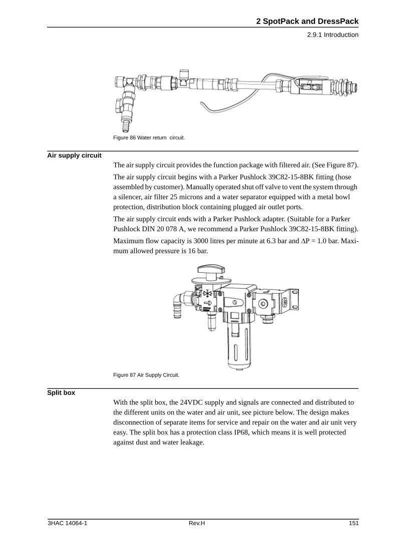
2 SpotPack and DressPack
2.9.1 Introduction
Figure 86 Water return circuit.
Air supply circuitThe air supply circuit provides the function package with filtered air. (See Figure 87).
The air supply circuit begins with a Parker Pushlock 39C82-15-8BK fitting (hose assembled by customer). Manually operated shut off valve to vent the system through a silencer, air filter 25 microns and a water separator equipped with a metal bowl protection, distribution block containing plugged air outlet ports.
The air supply circuit ends with a Parker Pushlock adapter. (Suitable for a Parker Pushlock DIN 20 078 A, we recommend a Parker Pushlock 39C82-15-8BK fitting).
Maximum flow capacity is 3000 litres per minute at 6.3 bar and �P = 1.0 bar. Maxi-mum allowed pressure is 16 bar.
Figure 87 Air Supply Circuit.
Split boxWith the split box, the 24VDC supply and signals are connected and distributed to the different units on the water and air unit, see picture below. The design makes disconnection of separate items for service and repair on the water and air unit very easy. The split box has a protection class IP68, which means it is well protected against dust and water leakage.
3HAC 14064-1 Rev.H 151
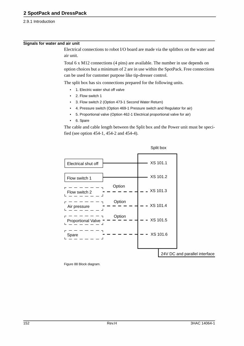
2 SpotPack and DressPack
2.9.1 Introduction
Signals for water and air unitElectrical connections to robot I/O board are made via the splitbox on the water and air unit.
Total 6 x M12 connections (4 pins) are available. The number in use depends on option choices but a minimum of 2 are in use within the SpotPack. Free connections can be used for customer purpose like tip-dresser control.
The split box has six connections prepared for the following units.
• 1. Electric water shut off valve
• 2. Flow switch 1
• 3. Flow switch 2 (Option 473-1 Second Water Return)
• 4. Pressure switch (Option 469-1 Pressure switch and Regulator for air)
• 5. Proportional valve (Option 462-1 Electrical proportional valve for air)
• 6. Spare
The cable and cable length between the Split box and the Power unit must be speci-fied (see option 454-1, 454-2 and 454-4).
Figure 88 Block diagram.
Electrical shut off
Flow switch 1
Flow switch 2
Air pressure
Proportional Valve
Spare
Option
Option
Option
Split box
XS 101.1
XS 101.2
XS 101.3
XS 101.4
XS 101.5
XS 101.6
24V DC and parallel interface
152 Rev.H 3HAC 14064-1
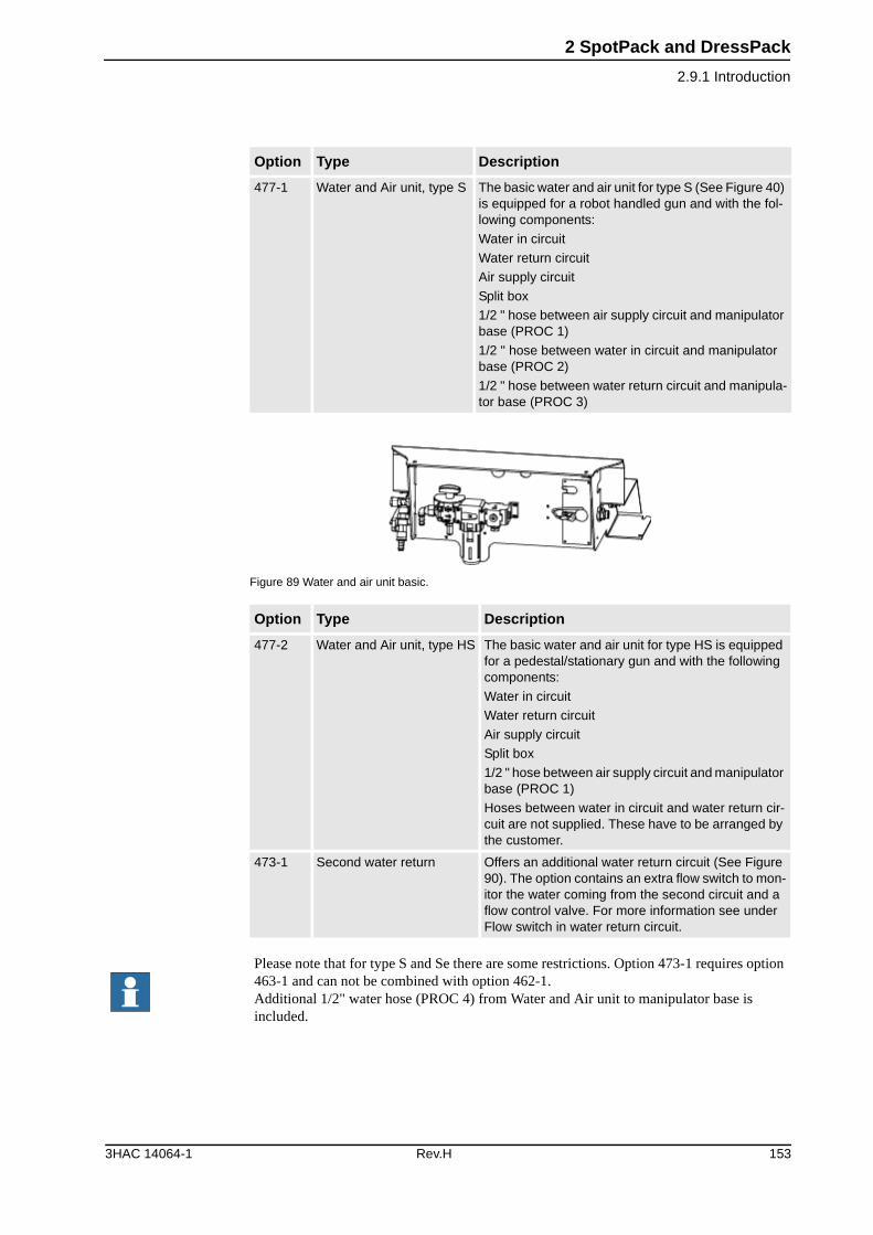
2 SpotPack and DressPack
2.9.1 Introduction
Figure 89 Water and air unit basic.
Option Type Description
477-1 Water and Air unit, type S The basic water and air unit for type S (See Figure 40) is equipped for a robot handled gun and with the fol-lowing components:
Water in circuit
Water return circuit
Air supply circuit
Split box
1/2 " hose between air supply circuit and manipulator base (PROC 1)
1/2 " hose between water in circuit and manipulator base (PROC 2)
1/2 " hose between water return circuit and manipula-tor base (PROC 3)
Option Type Description
477-2 Water and Air unit, type HS The basic water and air unit for type HS is equipped for a pedestal/stationary gun and with the following components:
Water in circuit
Water return circuit
Air supply circuit
Split box
1/2 " hose between air supply circuit and manipulator base (PROC 1)
Hoses between water in circuit and water return cir-cuit are not supplied. These have to be arranged by the customer.
473-1 Second water return Offers an additional water return circuit (See Figure 90). The option contains an extra flow switch to mon-itor the water coming from the second circuit and a flow control valve. For more information see under Flow switch in water return circuit.
Please note that for type S and Se there are some restrictions. Option 473-1 requires option 463-1 and can not be combined with option 462-1. Additional 1/2" water hose (PROC 4) from Water and Air unit to manipulator base is included.
3HAC 14064-1 Rev.H 153
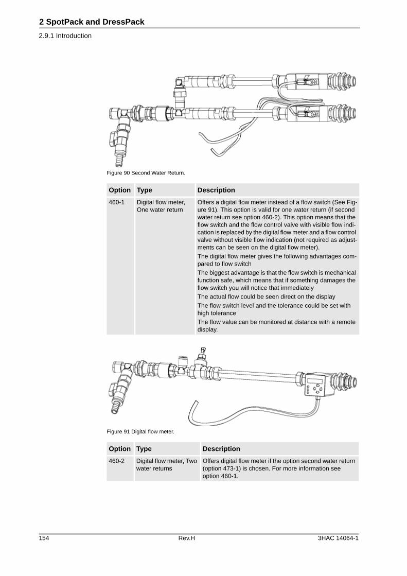
2 SpotPack and DressPack
2.9.1 Introduction
Figure 90 Second Water Return.
Figure 91 Digital flow meter.
Option Type Description
460-1 Digital flow meter, One water return
Offers a digital flow meter instead of a flow switch (See Fig-ure 91). This option is valid for one water return (if second water return see option 460-2). This option means that the flow switch and the flow control valve with visible flow indi-cation is replaced by the digital flow meter and a flow control valve without visible flow indication (not required as adjust-ments can be seen on the digital flow meter).
The digital flow meter gives the following advantages com-pared to flow switch
The biggest advantage is that the flow switch is mechanical function safe, which means that if something damages the flow switch you will notice that immediately
The actual flow could be seen direct on the display
The flow switch level and the tolerance could be set with high tolerance
The flow value can be monitored at distance with a remote display.
Option Type Description
460-2 Digital flow meter, Two water returns
Offers digital flow meter if the option second water return (option 473-1) is chosen. For more information see option 460-1.
154 Rev.H 3HAC 14064-1
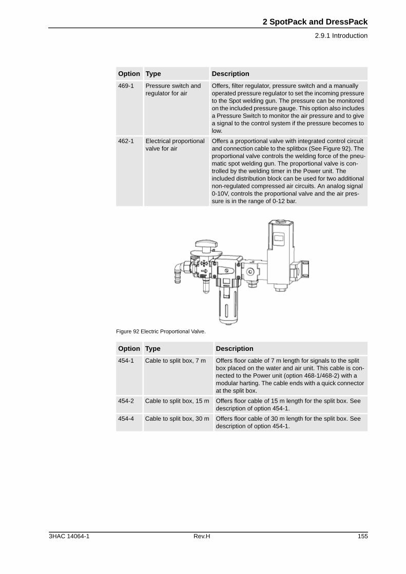
2 SpotPack and DressPack
2.9.1 Introduction
Figure 92 Electric Proportional Valve.
469-1 Pressure switch and regulator for air
Offers, filter regulator, pressure switch and a manually operated pressure regulator to set the incoming pressure to the Spot welding gun. The pressure can be monitored on the included pressure gauge. This option also includes a Pressure Switch to monitor the air pressure and to give a signal to the control system if the pressure becomes to low.
462-1 Electrical proportional valve for air
Offers a proportional valve with integrated control circuit and connection cable to the splitbox (See Figure 92). The proportional valve controls the welding force of the pneu-matic spot welding gun. The proportional valve is con-trolled by the welding timer in the Power unit. The included distribution block can be used for two additional non-regulated compressed air circuits. An analog signal 0-10V, controls the proportional valve and the air pres-sure is in the range of 0-12 bar.
Option Type Description
454-1 Cable to split box, 7 m Offers floor cable of 7 m length for signals to the split box placed on the water and air unit. This cable is con-nected to the Power unit (option 468-1/468-2) with a modular harting. The cable ends with a quick connector at the split box.
454-2 Cable to split box, 15 m Offers floor cable of 15 m length for the split box. See description of option 454-1.
454-4 Cable to split box, 30 m Offers floor cable of 30 m length for the split box. See description of option 454-1.
Option Type Description
3HAC 14064-1 Rev.H 155
2 SpotPack and DressPack
2.9.2 Interface description Water and Air unit
2.9.2 Interface description Water and Air unit
GeneralThe interface towards the Water and Air unit is described in table below.
General Technical data
The water hoses (Proc 2 and Proc 3) are cross-connected at the end at axis 6 (the pressure drop is measured without any tool).
Type Pcs Specification
Connections for media
Incoming water 1 Parker Pushlock 33482-8-8BK fitting for ���hosea
a. Connection to be made by customer.
Outgoing water 1 Parker Pushlock 33482-8-8BK fitting for ���hosea
Incoming air 1 Parker Pushlock 33482-8-8BK fitting for ���hosea
Extra air outlet 1 ���connectionb
b. Plugged at delivery (to be used for tip-dresser or other equipment). (Fitting 1/2"BSP 1,5).
Data Description
Maximum water pressure 10 bar / 145 PSI
Maximum air pressure 16 bar / 230 PSI
Maximum pressure drop 0,35 bar at 6 liter/minutea
a. The pressure drop is measured under the following conditions:Measuring point 1: Incoming water connection at water and air unit.Measuring point 2: Outgoing water connection at water and air unit.
Water quality Normal filtered industrial water quality
Air quality
156 Rev.H 3HAC 14064-1
2 SpotPack and DressPack
2.10.1 Options
2.10 Connection kits
2.10.1 Options
Option 459-1CP/CS, Proc 1 on base
This option offers a kit with connectors. This must be assembled by the customer. The kit contains:
• 1 Hose fittings (Parker Pushlock, (½”, M22x1,5 Brass, 24 degree seal))
• Connector with:
Option 480-1Weld, Proc 2-4 on base
This option offers a kit with weld connector and fittings. This must be assembled by the customer. The kit contains:
• 3 Hose fittings (Parker Pushlock, (½”, M22x1,5 Brass, 24 degree seal))
• Weld connector with:
1 pcs Hood Foundry (Harting) HAN EMC / M 40
1 pcs Hinged frame (Harting) Shell size 16
2 pcs Multicontact, female (Harting) Type HD (25 pin)
1 pcs Multicontact, female (Harting) Type EE (8 pin)
1 pcs Multicontact, female (Harting) Type DD (12 pin)
10 pcs Female crimp contacts For 1,5 mm²
10 pcs Female crimp contacts For 0,5 mm²
10 pcs Female crimp contacts For 0,75-1,0 mm²
10 pcs Female crimp contacts For 2,5 mm²
12 pcs Female crimp contacts For 0,14 – 0,37 mm²
45 sockets For 0,2 – 0,56 mm²
Assembly Accessories to complete connector
Assembly instruction
1 pcs Welding connector socket (MC) 3x35 mm²
1 pcs Cable gland, plastic Diameter 24-28 mm
Assembly Accessories to complete connector
Assembly instruction
3HAC 14064-1 Rev.H 157
2 SpotPack and DressPack
2.10.1 Options
Option 474-1SW1, SW 2/3 on base
This option offers a kit with two connectors. This must be assembled by the cus-tomer. The kit contains:
• Connector for SW1 with:
• Connector for SW2/3 with:
Option 453-1FB 7
This option offers a kit with a connector. This must be assembled by the customer. The kit contains:
• Connector with:
1 pcs Socket connector (32p) Souriau UTOW
1 pcs Adaptor Used with form shrink
35 pcs Sockets Souriau UTOW for 0,13-0,25 mm²
Assembly Accessories to complete connector
Assembly instruction
1 pcs Socket connector (32p) Souriau UTOW, Rotated version(85 degrees)
1 pcs Adaptor Used with form shrink
35 pcs Sockets Souriau UTOW for 0,13-0,25 mm²
Assembly Accessories to complete connector
Assembly instruction
1 pcs Multiple connector (pin) Burndy
1 pcs Adaptor 12 pin
15 pcs Pin For 0,13-0,25 mm²
Assembly Accessories to complete connector
Assembly instruction
158 Rev.H 3HAC 14064-1
2 SpotPack and DressPack
2.10.1 Options
Option 458-1CP/CS, Proc 1 axis 3
This option offers a kit with connectors. This must be assembled by the customer. The kit contains:
• 1 Hose fittings (Parker Pushlock, (½”, M22x1,5 Brass, 24 degree seal))
• Connector with:
Option 479-1Weld, Proc 2-4 axis 3
This option offers a kit with weld connector and fittings. This must be assembled by the customer. The kit contains:
• 3 Hose fittings (Parker Pushlock, (½”, M22x1,5 Brass, 24 degree seal))
• Weld connector with:
Option 452-1Connection kit, Axis 6 robot side SW
The process cable package from axis 3 to axis 6 (option 475-1) ends with free end for media and for weld power cable. The option 452-1 offers a kit for connectors. This must be assembled by the customer when hoses and power cable has been cut to required length. The kit contains:
• 4 Hose fittings (Parker Pushlock, (½”, M22x1,5 Brass, 24 degree seal))
• 1 Multi contact connector (Female) type including:
1 pcs Hood Foundry (Harting) HAN EMC / M 40
1 pcs Hinged frame (Harting) Shell size 16
2 pcs Multicontact, female (Harting) Type HD (25 pin)
1 pcs Multicontact, female (Harting) Type EE (8 pin)
1 pcs Multicontact, female (Harting) Type DD (12 pin)
10 pcs Male crimp contacts For 1,5 mm²
10 pcs Male crimp contacts For 0,5 mm²
10 pcs Male crimp contacts For 0,75-1,0 mm²
10 pcs Male crimp contacts For 2,5 mm²
12 pcs Male crimp contacts For 0,14 – 0,37 mm²
45 pins For 0,2 – 0,56 mm²
1 pcs Welding connector pin with flange (MC) 3x35 mm² (25 mm² pin)
1 pcs Cable gland, plastic Diameter 24-28 mm
Assembly Accessories to complete connector
Assembly instruction
Welding contactor socket (MC) 3x25 mm²
Cable gland plastic PG 29 diam 28-24
End housing Eg-TS Pg29/100
3HAC 14064-1 Rev.H 159

2 SpotPack and DressPack
2.10.1 Options
160 Rev.H 3HAC 14064-1
3 Specification of Variants and Options
3.1.1 General
3 Specification of Variants and Options
3.1 Introduction
3.1.1 General
The different variants and options for the IRB 6600 are described following sections.
The same numbers are used here as in the Specification form. For controller options, see Product specification - Controller, S4Cplus, and Controller, S4Cplus Automotive and for software options, see Product specification - RobotWare 4.0.
3.1.2 Manipulator
Variants
Manipulator color
Protection
Option IRB Type Handling capacity (kg)/Reach (m)
435-22 6600 175/2.8
435-17 6600 225/2.55
435-16 6600 175/2.55
435-30 6650 125/3.2
435-19 6650 200/2.75
435-50 6650S 125/3.5
435-51 6650S 200/3.0
Option Description Note
209-1 Standard The manipulator is painted in ABB orange.
209-4 --192 RAL code Colors according to RAL-codes.
Option Description Note
287-4 Standard (IP 67)
287-3 Foundry Robot adapted for foundry or other harsh environments.
The robot has the FoundryPlus protection which means that the whole manipulator is steam washable. The excellent corrosion protection is obtained by a special coating. The connectors are designed for severe environment, and bear-ings, gears and other sensitive parts are highly protected.
3HAC 14064-1 Rev.H 161
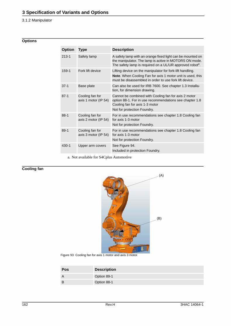
3 Specification of Variants and Options
3.1.2 Manipulator
Options
Cooling fan
Figure 93 Cooling fan for axis 1 motor and axis 3 motor.
Option Type Description
213-1 Safety lamp A safety lamp with an orange fixed light can be mounted on the manipulator. The lamp is active in MOTORS ON mode. The safety lamp is required on a UL/UR approved robota.
a. Not available for S4Cplus Automotive
159-1 Fork lift device Lifting device on the manipulator for fork-lift handling.
Note. When Cooling Fan for axis 1 motor unit is used, this must be disassembled in order to use fork lift device.
37-1 Base plate Can also be used for IRB 7600. See chapter 1.3 Installa-tion, for dimension drawing.
87-1 Cooling fan for axis 1 motor (IP 54)
Cannot be combined with Cooling fan for axis 2 motor option 88-1. For in use recommendations see chapter 1.8 Cooling fan for axis 1-3 motor
Not for protection Foundry.
88-1 Cooling fan for axis 2 motor (IP 54)
For in use recommendations see chapter 1.8 Cooling fan for axis 1-3 motor
Not for protection Foundry.
89-1 Cooling fan for axis 3 motor (IP 54)
For in use recommendations see chapter 1.8 Cooling fan for axis 1-3 motor
Not for protection Foundry.
430-1 Upper arm covers See Figure 94.
Included in protection Foundry.
Pos Description
A Option 89-1
B Option 88-1
(A)
(B)
162 Rev.H 3HAC 14064-1
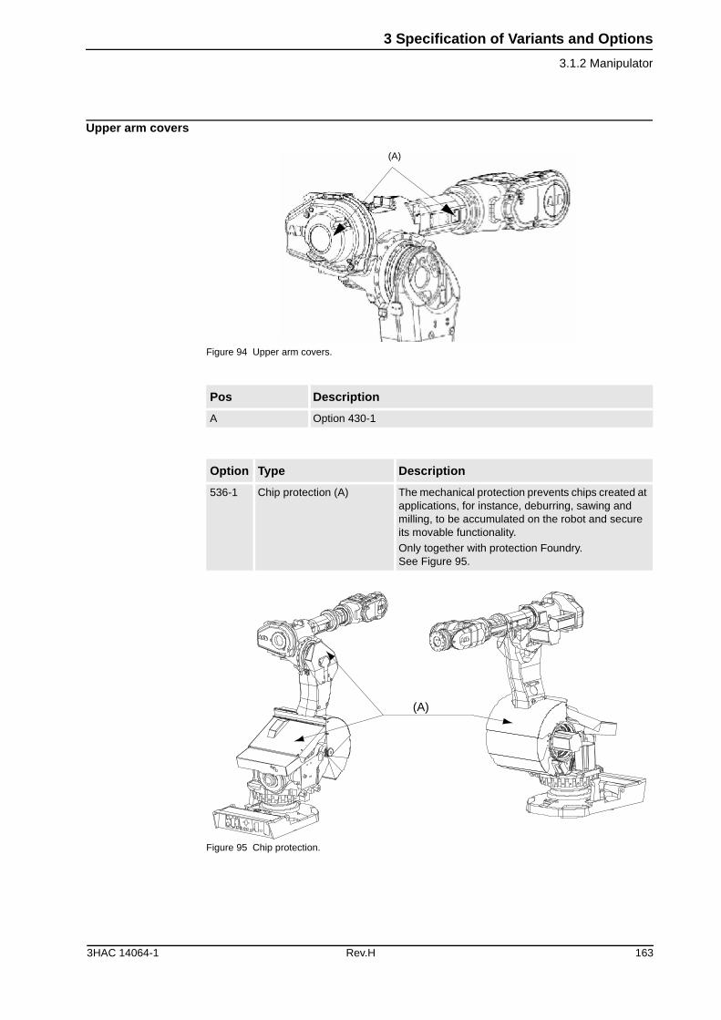
3 Specification of Variants and Options
3.1.2 Manipulator
Upper arm covers
Figure 94 Upper arm covers.
Figure 95 Chip protection.
Pos Description
A Option 430-1
Option Type Description
536-1 Chip protection (A) The mechanical protection prevents chips created at applications, for instance, deburring, sawing and milling, to be accumulated on the robot and secure its movable functionality.
Only together with protection Foundry.See Figure 95.
(A)
(A)
3HAC 14064-1 Rev.H 163
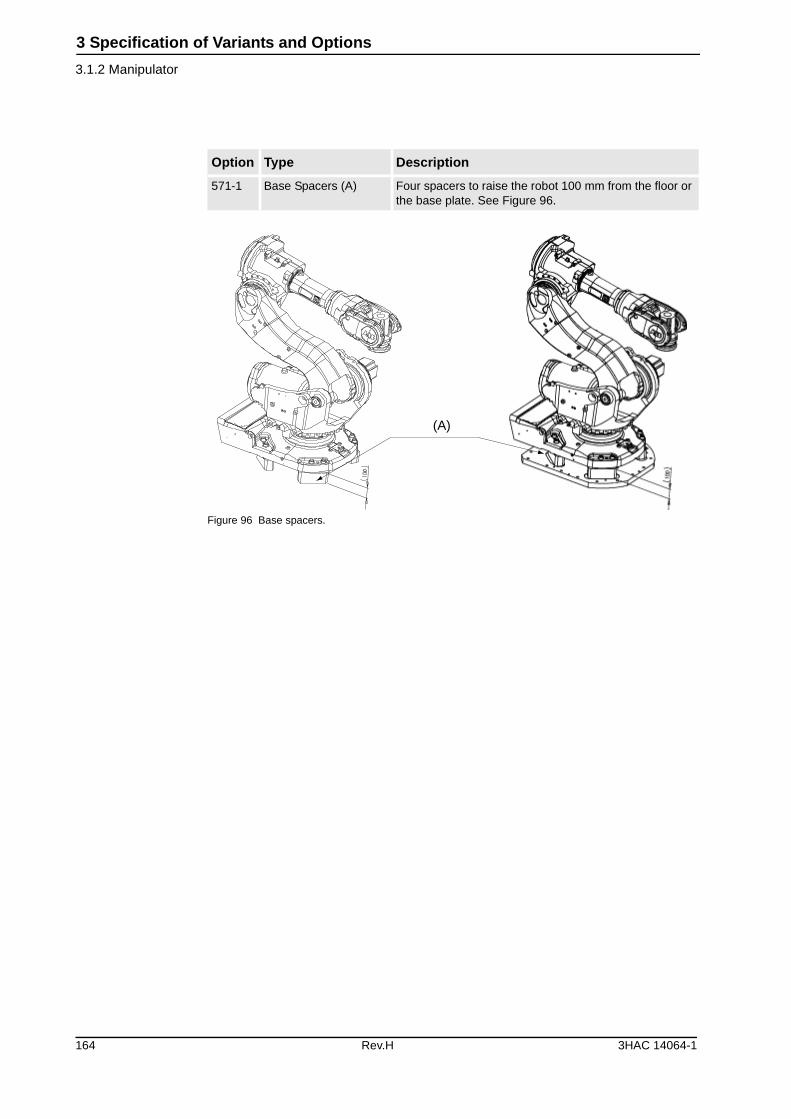
3 Specification of Variants and Options
3.1.2 Manipulator
Figure 96 Base spacers.
Option Type Description
571-1 Base Spacers (A) Four spacers to raise the robot 100 mm from the floor or the base plate. See Figure 96.
(A)
164 Rev.H 3HAC 14064-1
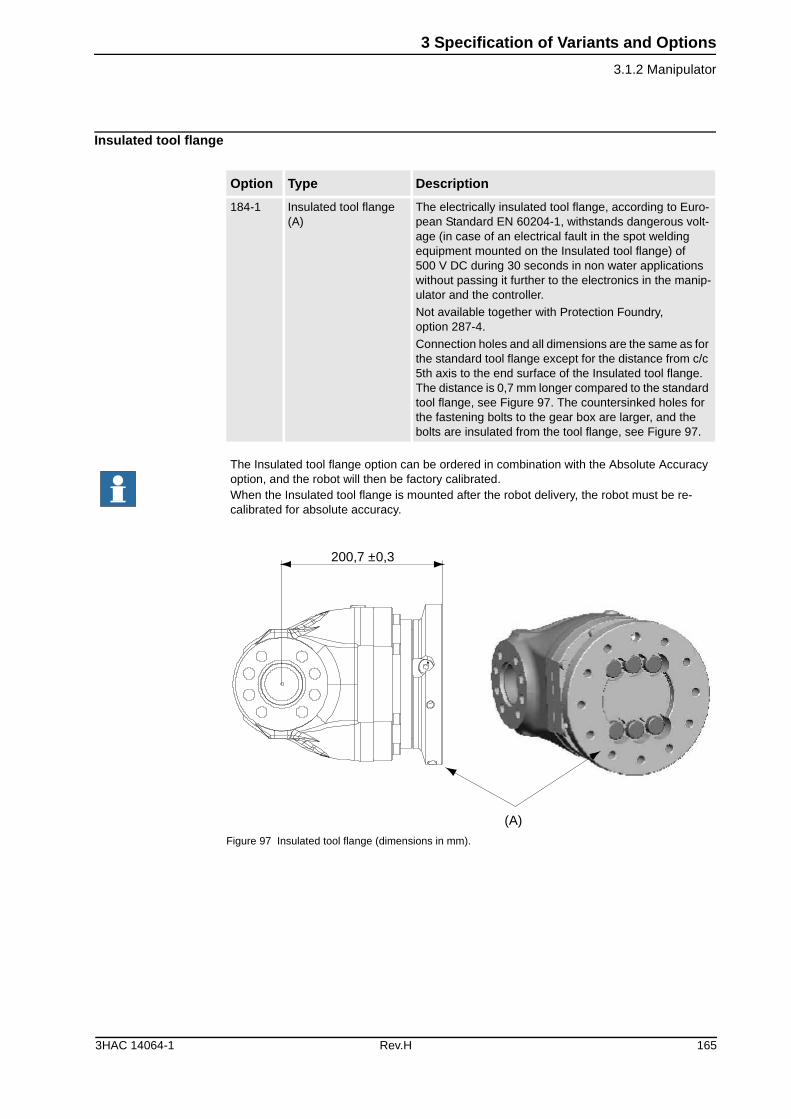
3 Specification of Variants and Options
3.1.2 Manipulator
Insulated tool flange
Figure 97 Insulated tool flange (dimensions in mm).
Option Type Description
184-1 Insulated tool flange (A)
The electrically insulated tool flange, according to Euro-pean Standard EN 60204-1, withstands dangerous volt-age (in case of an electrical fault in the spot welding equipment mounted on the Insulated tool flange) of 500 V DC during 30 seconds in non water applications without passing it further to the electronics in the manip-ulator and the controller.
Not available together with Protection Foundry, option 287-4.
Connection holes and all dimensions are the same as for the standard tool flange except for the distance from c/c 5th axis to the end surface of the Insulated tool flange. The distance is 0,7 mm longer compared to the standard tool flange, see Figure 97. The countersinked holes for the fastening bolts to the gear box are larger, and the bolts are insulated from the tool flange, see Figure 97.
The Insulated tool flange option can be ordered in combination with the Absolute Accuracy option, and the robot will then be factory calibrated.When the Insulated tool flange is mounted after the robot delivery, the robot must be re-calibrated for absolute accuracy.
(A)
200,7 ±0,3
3HAC 14064-1 Rev.H 165
3 Specification of Variants and Options
3.1.3 Position Switches
3.1.3 Position Switches
GeneralPosition switches indicating the position of the three main axes. Rails with separate adjustable cams are attached to the manipulator. The cams, which have to be adapted to the switch function by the user, can be mounted in any position in the working range for each switch. No machining operation of the cams is necessary for the adap-tation, simple hand tools can be used.
FunctionFor axis 1, there are three redundant position zones available, each with two indepen-dent switches and cams. For axes 2 and 3, two channels position zones are available, each with two independent switches and cams.
Each position zone consists of two switches mechanically operated by separate cams. Each switch has one normally open and one normally closed contact. The design and components fulfill the demands to be used as safety switches. These options may require external safety arrangements, e.g. light curtains, photocells or contact mats.
The switches can be connected either to the manipulator base(R1.SW1 and R1.SW2/3, see Figure 52), or to the controller. In the controller the signals are connected to screw terminal XT8 Phoenix MSTB 2.5/12-ST-5.08. Switch type Balluff Multiple position switches BNS, according to EN 60947-5-1 and EN 60947-5-2.
Position switches
Option Type Description
25-3 Position switches axis 1 Three redundant position zones are available, each with two independent switches and cams.
Two plus one zone.
30-1 Position switches axis 2 Two redundant position zones are available, one with two independent switches and cams, and the other with one independent switch and cam. Not for protection foundry, (option 287-3).
33-1 Position switches axis 3 Two redundant position zones are available, one with two independent switches and cams, and the other with one independent switch and cam. Not for protection foundry, (option 287-3).
166 Rev.H 3HAC 14064-1
3 Specification of Variants and Options
3.1.3 Position Switches
Connection to
Connection of signals axis 1(cable lengths)
Connection of signals axes 2 and 3 (cable lengths)
Working Range LimitTo increase the safety of the robot, the working range of axes 1, 2 and 3 can be restricted by extra mechanical stops.
Extended work range
Option Type Description
271-2 Manipulator Connection on the manipulator base with one/two Souriau 32-pin connector.
271-1 Cabinet Connection inside the cabinet wall. See Product specifi-cation - Controller, S4Cplus. Position switch cables are included.
Option Lengths
273-1 7 m
273-2 15 m
273-4 30 m
Option Lengths
274-1 7 m
274-2 15 m
274-4 30 m
Option Type Description
29-2 Axis 1, 7,5 degrees Four stops, two which allow the working range to be restricted in increments of 15º and two stops of 7,5º.
29-1 Axis 1, 15 degrees Two stops which allow the working range to be restricted in increments of 15º.
32-1 Axis 2 Six stops which allow the working range to be restricted in increments of 15º at both end positions. Each stop decreases the motion by 15º.
34-1 Axis 3 Six stops which allow the working range to be restricted in increments of 20º at both end positions. Each stop decreases the motion by 20º.
Option Type Description
561-1 Extended work range axis 1
To extend the working range on Axis 1 from ± 180ºto ± 220º.
When the option is used the mechanical stop shall be disassembled.
Position switches axis 1, option 25-3, are required.
3HAC 14064-1 Rev.H 167
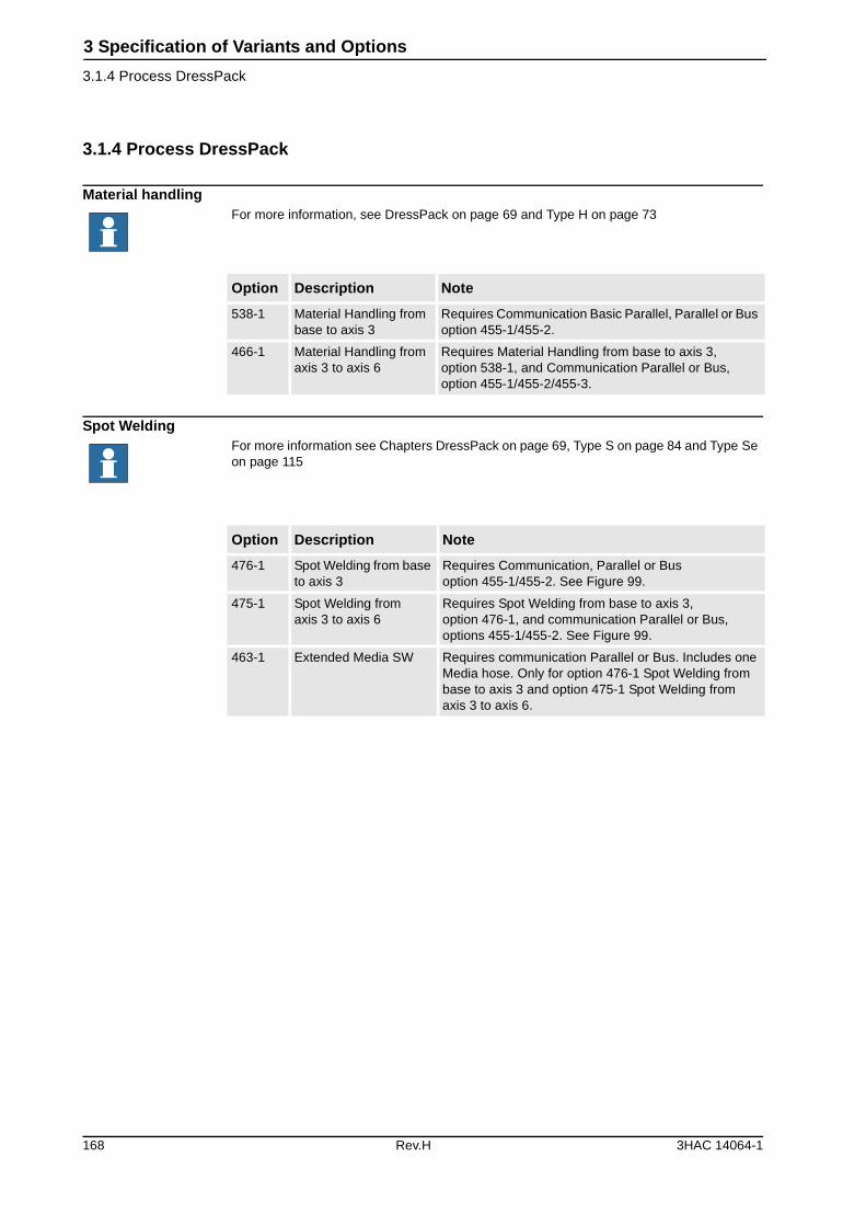
3 Specification of Variants and Options
3.1.4 Process DressPack
3.1.4 Process DressPack
Material handling
Spot Welding
For more information, see DressPack on page 69 and Type H on page 73
Option Description Note
538-1 Material Handling from base to axis 3
Requires Communication Basic Parallel, Parallel or Bus option 455-1/455-2.
466-1 Material Handling from axis 3 to axis 6
Requires Material Handling from base to axis 3, option 538-1, and Communication Parallel or Bus, option 455-1/455-2/455-3.
For more information see Chapters DressPack on page 69, Type S on page 84 and Type Se on page 115
Option Description Note
476-1 Spot Welding from base to axis 3
Requires Communication, Parallel or Busoption 455-1/455-2. See Figure 99.
475-1 Spot Welding from axis 3 to axis 6
Requires Spot Welding from base to axis 3,option 476-1, and communication Parallel or Bus, options 455-1/455-2. See Figure 99.
463-1 Extended Media SW Requires communication Parallel or Bus. Includes one Media hose. Only for option 476-1 Spot Welding from base to axis 3 and option 475-1 Spot Welding from axis 3 to axis 6.
168 Rev.H 3HAC 14064-1
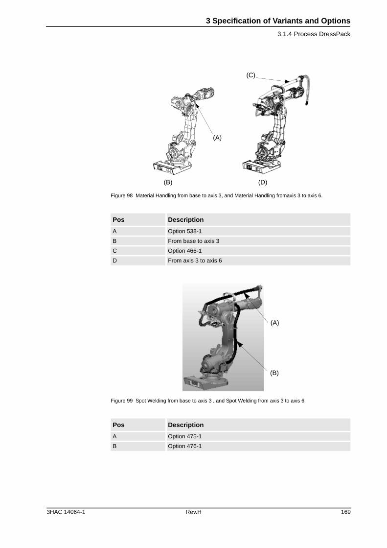
3 Specification of Variants and Options
3.1.4 Process DressPack
Figure 98 Material Handling from base to axis 3, and Material Handling fromaxis 3 to axis 6.
Figure 99 Spot Welding from base to axis 3 , and Spot Welding from axis 3 to axis 6.
Pos Description
A Option 538-1
B From base to axis 3
C Option 466-1
D From axis 3 to axis 6
Pos Description
A Option 475-1
B Option 476-1
(A)
(B)
(C)
(D)
(A)
(B)
3HAC 14064-1 Rev.H 169
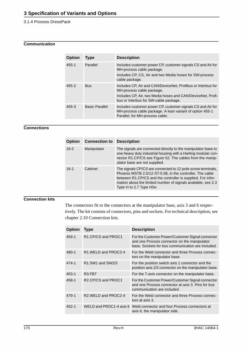
3 Specification of Variants and Options
3.1.4 Process DressPack
Communication
Connections
Connection kitsThe connectors fit to the connectors at the manipulator base, axis 3 and 6 respec-tively. The kit consists of connectors, pins and sockets. For technical description, see chapter 2.10 Connection kits.
Option Type Description
455-1 Parallel Includes customer power CP, customer signals CS and Air for MH-process cable package.
Includes CP, CS, Air and two Media hoses for SW-process cable package.
455-2 Bus Includes CP, Air and CAN/DeviceNet, Profibus or Interbus for MH-process cable package.
Includes CP, Air, two Media hoses and CAN/DeviceNet, Profi-bus or Interbus for SW-cable package.
455-3 Basic Parallel Includes customer power CP, customer signals CS and Air for MH-process cable package. A lean variant of option 455-1 Parallel, for MH-process cable.
Option Connection to Description
16-2 Manipulator The signals are connected directly to the manipulator base to one heavy duty industrial housing with a Harting modular con-nector R1.CP/CS see Figure 52. The cables from the manip-ulator base are not supplied.
16-1 Cabinet The signals CP/CS are connected to 12-pole screw terminals, Phoenix MSTB 2.5/12-ST-5.08, in the controller. The cable between R1.CP/CS and the controller is supplied. For infor-mation about the limited number of signals available, see 2.3 Type H to 2.7 Type HSe
Option Type Description
459-1 R1.CP/CS and PROC1 For the Customer Power/Customer Signal connector and one Process connector on the manipulator base. Sockets for bus communication are included.
480-1 R1.WELD and PROC2-4 For the Weld connector and three Process connec-tors on the manipulator base.
474-1 R1.SW1 and SW2/3 For the position switch axis 1 connector and the position axis 2/3 connector on the manipulator base.
453-1 R3.FB7 For the 7-axis connector on the manipulator base.
458-1 R2.CP/CS and PROC1 For the Customer Power/Customer Signal connector and one Process connector at axis 3. Pins for bus communication are included.
479-1 R2.WELD and PROC2-4 For the Weld connector and three Process connec-tors at axis 3.
452-1 WELD and PROC1-4 axis 6 Weld connector and four Process connectors at axis 6, the manipulator side.
170 Rev.H 3HAC 14064-1
3 Specification of Variants and Options
3.1.5 Floor cables
3.1.5 Floor cables
Standard/CAN DeviceNet/Interbus/Profibus
Robot Servo Gun Extended/Stationary Servo GunFollowing information specifies the cable length for Robot Servo Gun Extended/Stationary Servo Gun.
3.1.6 SpotPack
Power UnitFor more information see chapter 2.8 Power Unit
Weld power cable
Option Lengths
94-1/90-2/91-2/92-2 7 m
94-2/90-3/91-3/92-3 15 m
94-4/90-5/91-5/92-5 30 m
Option Lengths
450-1/95-1 7 m
450-2/95-2 15 m
450-4/95-4 30 m
Option Description
468-1 Power unit AC welding type S
468-2 Power unit AC welding type HS
465-1 MFDC welding S and HS
461-1 Earth fault protection
464-1 Forced air cooling
457-1 Contactor for welding power
Option Lengths
478-1 7 m
478-2 15 m
3HAC 14064-1 Rev.H 171
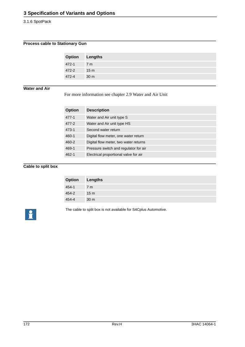
3 Specification of Variants and Options
3.1.6 SpotPack
Process cable to Stationary Gun
Water and Air For more information see chapter 2.9 Water and Air Unit
Cable to split box
Option Lengths
472-1 7 m
472-2 15 m
472-4 30 m
Option Description
477-1 Water and Air unit type S
477-2 Water and Air unit type HS
473-1 Second water return
460-1 Digital flow meter, one water return
460-2 Digital flow meter, two water returns
469-1 Pressure switch and regulator for air
462-1 Electrical proportional valve for air
Option Lengths
454-1 7 m
454-2 15 m
454-4 30 m
The cable to split box is not available for S4Cplus Automotive.
172 Rev.H 3HAC 14064-1
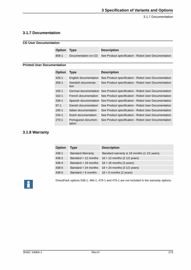
3 Specification of Variants and Options
3.1.7 Documentation
3.1.7 Documentation
CD User Documentation
Printed User Documentation
3.1.8 Warranty
Option Type Description
808-1 Documentation on CD See Product specification - Robot User Documentation
Option Type Description
428-1 English documentation See Product specification - Robot User Documentation
358-1 Swedish documenta-tion
See Product specification - Robot User Documentation
165-1 German documentation See Product specification - Robot User Documentation
162-1 French documentation See Product specification - Robot User Documentation
336-1 Spanish documentation See Product specification - Robot User Documentation
97-1 Danish documentation See Product specification - Robot User Documentation
195-1 Italian documentation See Product specification - Robot User Documentation
234-1 Dutch documentation See Product specification - Robot User Documentation
270-1 Portuguese documen-tation
See Product specification - Robot User Documentation
Option Type Description
438-1 Standard Warranty Standard warranty is 18 months (1 1/2 years)
438-2 Standard + 12 months 18 + 12 months (2 1/2 years)
438-4 Standard + 18 months 18 + 18 months (3 years)
438-5 Standard + 24 months 18 + 24 months (3 1/2 years)
438-6 Standard + 6 months 18 + 6 months (2 years)
DressPack options 538-1, 466-1, 476-1 and 475-1 are not included in the warranty options.
3HAC 14064-1 Rev.H 173

3 Specification of Variants and Options
3.1.8 Warranty
174 Rev.H 3HAC 14064-1

4 Accessories
4 Accessories
GeneralThere are a range of tools and equipment available, specially designed for the robot.
Basic software and software options for robot and PCFor more information, see Product Specification - Controller, S4Cplus, and Product Specification - RobotWare 4.0.
Robot Peripherals• Track Motion
• Motor Units
3HAC 14064-1 Rev.H 175

4 Accessories
176 Rev.H 3HAC 14064-1
Index
A
accessories, 175Active Brake System, 13
C
Collision detection, 14colours, 161cooling device, 9
E
Electronically Stabilised Path, 14emergency stop, 16enabling device, 16equipment
mounting, 45permitted extra load, 45
F
fire safety, 17fork lift device, 162
H
hold-to-run control, 17hole configuration, 21holes for mounting extra equipment, 47humidity, 19
I
installation, 18Internal Safety Concept, 16
L
lifting device, 162limit switches, 15, 18load, 18, 20load diagrams, 32
M
maintenance, 51manipulator colour, 161mechanical interface, 49, 50motion, 52mounting
extra equipment, 45robot, 20
mounting flange, 49, 50
N
noise level, 9
O
operating requirements, 19options, 161overspeed protection, 14
P
Passive Safety System, 15payload, 18
position switches, 15, 18protection, 161protection standards, 19
R
range of movement, 52reduced speed, 16Robot Gun, 60Robot Gun and Track Motion, 64Robot Peripherals, 175robot tool flange, 49, 50robot versions, 8
S
safeguarded space stop, 17delayed, 17
safety, 12Safety category 3, 16safety lamp, 17, 162Self Tuning Performance, 13service, 51Service Information System, 12space requirements, 9standards, 12Stationary and Robot Gun, 61Stationary Gun, 59Stationary Gun and Track Motion, 63structure, 7
T
temperature, 19troubleshooting, 51Twin Stationary Guns, 62
V
variants, 161
W
working spacerestricting, 14, 18, 167, 173
Z
zone switches, 15
3HAC 14064-1 Rev.H 177

Index
178 Rev.H 3HAC 14064-1


ABB Automation Technologies ABRoboticsS-721 68 VÄSTERÅSSWEDENTelephone: +46 (0) 21 344000Telefax: +46 (0) 21 132592
3HA
C 1
4064
-1, R
evis
ion
H, e
n