Embed Size (px)
Citation preview
Technical Description
47
Product Safety Assessment Initiatives for a Hydrogen Society
In our hydrogen energy supply chain pilot project, for safer use of hydrogen products, we had many phenomenological experiments, numerical analysis and risk assessments to clarify the hydrogen behavior. And we are also developing management systems for health, safety, and environment in our project.
Introduction
To establish a hydrogen energy supply chain that supports the realization of a hydrogen-based society, we need to establish a process for evaluating safety that covers the entire life cycle of products in addition to technology development, and also demonstrate to the public that hydrogen products can be used safely.
1 Background
Liquefied natural gas (LNG) is currently used as one of clean energy. In the 1950s, a wide range of technological advancements were made in the transportation, storage, and utilization of LNG, which led to it becoming very widespread throughout society. The use of hydrogen, on the other hand, started with specialized applications such as rockets, for which Kawasaki developed liquefied hydrogen storage tanks in the 1970s for the Tanegashima Space Center of the Japan Aerospace Exploration Agency (JAXA). Ever since then, more and more hydrogen stations for fuel cell vehicles have opened, and hydrogen is gaining momentum toward full-scale utilization. To handle hydrogen safely, comprehensive approaches are required, such as phenomenological experiments , numerical analyses and appropriate safety assessments before development and design verification. Moreover, as a product supplier, we need to promote organizational safety efforts through every development phase of the entire product life cycle, from the initial concept to actual use.
2 What is hydrogen?1)
(1) Properties of hydrogen Table 1 shows the physical properties of hydrogen comparing them to methane, the main component of LNG. The liquefied hydrogen improves transport efficiency, but liquefied hydrogen requires more advanced thermal insulation technology than LNG, because its boiling point is approximately 90°C lower and it has smaller latent heat per volume than LNG. Moreover, once vaporized, hydrogen ignites much more easily than methane and burning velocity is faster after ignition, which means it requires prevention measures not only for leakage but also for ignition. Therefore, basic measures are important, such as preventing hydrogen gas leakage, so as not to generate flammable atmosphere within the combustion range, and avoiding ignition sources.
(2) Regulations and guidelines that apply to the hydrogen project
The terminal facilities are built in accordance with the domestic regulations where the construction site is
Table 1 Physical properties of liquefied hydrogen and LNG
Physical property Hydrogen LNG (methane)
Boiling point 〔°C〕 -252. 85 -161. 45
Gas density 〔kg/m3〕 0. 0899 0. 717
Liquid density 〔kg/m3〕 70. 8 422. 4
Latent heat 〔kJ/L〕 31. 4 246
Flammability limits (in air) 〔vol%〕 4~75 5~15
Minimum ignition energy 〔10-5 J〕 1. 6 28
技術07E_210113.indd 47 2021/02/02 11:13:35
48
located. The High Pressure Gas Safety Act is one of them and regulations for hydrogen supply facilities are being developed. On the other hand, for the carriage of liquefied gases in bulk by ships, the ships should comply with the relevant requirements in the IGC Code, set by the International Maritime Organization (IMO). However, the requirements for liquefied hydrogen are not specified in the Code. For this reason, in 2013 Ministry of Land, Infrastructure, Transport and Tourism established a working group of experts and started discussions on safety standards. Japan made a proposal to the IMO, and interim recommendations for carriage of liquefied hydrogen in bulk were adopted in 2016 2). As the interim recommendations require that safety measures be considered based on a risk assessment, the assessment results on the basic design of the pilot ship Kawasaki designed have been published by the IMO 3). After that, Class NK instituted Guidelines for Liquefied Hydrogen Carriers corresponding to the interim recommendations. Major standards and guidelines are shown in Table 2.
3 To Ensure safety
Today, systems are becoming more and more complex at an increasingly fast pace, so it is becoming more difficult to ensure product safety just based on past experience, designing achievements, and complying with the regulations at the time. In Europe and the U.S. in the energy and chemical plant industry, they not only comply with laws, regulations, and industry standards, but also voluntarily set even stricter
standards, and moreover, they have established a product development scheme based on risk assessment by manufacturers or operators. In Japan, related laws and regulations are changing from a specification-based approach that defines specific criteria, to a performance-based approach, which only defines a specific level of performance and leaves it up to manufacturers how they achieve the requirements. In the latter approach, risk assessment becomes an effective method of demonstrating accountability. Risk assessment is a series of steps in which risk inherent in systems is identified, estimated and evaluated. And it determines proper risk reduction measures to be planned according to the results. In order to provide safety hydrogen products, from a technical standpoint, we are required to design products based on adequate risk assessment results and also to conduct phenomenological experiments to clarify the behavior of hydrogen and numerical analyses using proven methods. Also, from the standpoint of project execution, we are required an integrated approach considering an occupational safety, health, and environmental.
4 Our approaches to safety
One of the most important points for risk assessment is to ensure the completeness of risk identification. As there are several methods of risk assessment, we selected one after considering the features of each method. The major assessment methods we adopted in this pilot project are shown in Table 3. To ensure objectivity, risk assessment was conducted by inviting external experts. Major external safety reviews
Table 2 Standards and guidelines for hydrogen safety
Kawasaki Technical Review No.182
February 2021
Scope Standards and guidelines
Related rules for lique�ed hydrogen carriers
Guidelines for Lique�ed Hydrogen Carriers, Class NK (2017)
Hydrogen safety ISO/TR 15916 : Basic considerations for the safety of hydrogen system (2016)
Hydrogen safety AIAA G-095 : Guide to Safety of Hydrogen and Hydrogen Systems (2014)
Hydrogen facilities NFPA 2 : Hydrogen Technologies Code (2016)
Method Features
HAZID(Hazard Identification) Comprehensively evaluates critical hazards inherent in an object
HAZOP(Hazard and Operability Studies)
Identi�es potential hazards in design deviation using a piping and instrumentation diagram (P&ID)
FMEA(Failure Modes and Effects Analysis)
Evaluates equipment failure mode, its effects, and detection methods
Bowtie Analysis Evaluates cause and consequence, and safety measures, with a focus on possible events
Table 3 Risk assessment methods in our pilot project
技術07E_210113.indd 4 2021/02/02 11:13:35
Technical Description
49
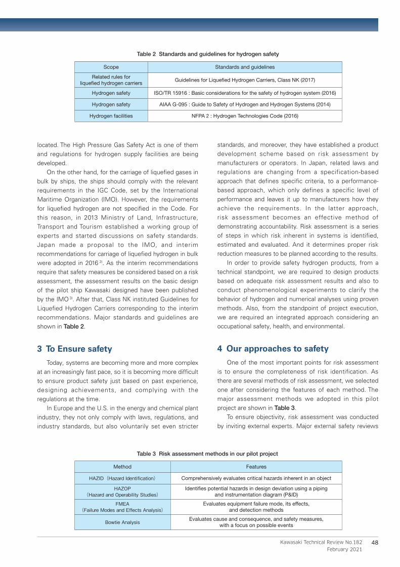
conducted for the pilot project are shown in Table 4. An image of a HAZOP study workshop, which is one of the assessment methods, is shown in Figure 1.
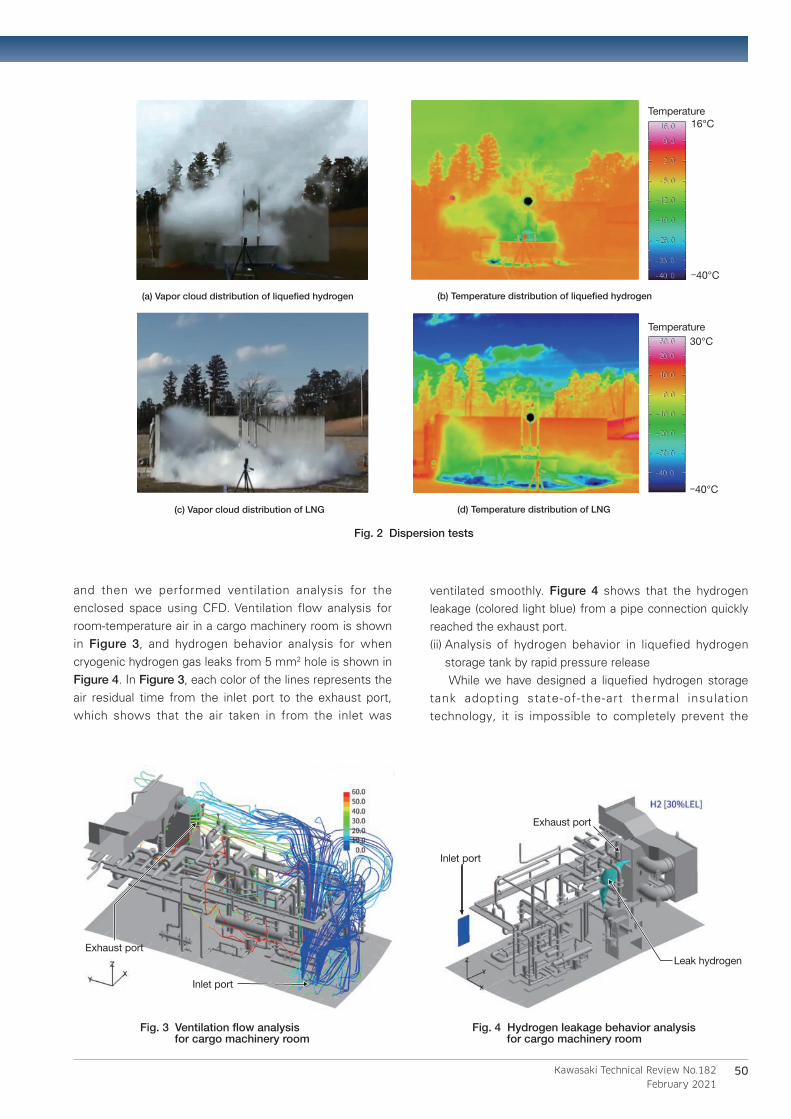
(1) Hydrogen behavior phenomenological experiment In order to identify various hydrogen behaviors that can be caused by an accident, we conducted a variety of experiments in collaboration with third parties. Figure 2 shows the results of liquefied hydrogen and LNG dispersion tests conducted in 2013. In these tests, we released approximately six liters of liquefied hydrogen and LNG from approximately 0.9 meters above stainless steel materials on the ground, observed the consequent vapor cloud distribution, and evaluated the spread speed and the effects caused by the material of the surface onto which the liquids were spilled. It was found that both of the low temperature fluids cooled the surrounding atmosphere and formed vapor clouds during the process of evaporation, but
the hydrogen gas showed a higher ascent velocity and smaller horizontal dispersion. In addition, it was observed from the temperature distribution that low temperature gas stagnated on the ground for LNG , but the same behavior was not observed for hydrogen.
(2) Numerical analysis( i ) Hydrogen leak analysis Because a ship has limited space in which to install equipment, some of the hydrogen cargo pipeline and equipment have to be installed in an enclosed space. Under such circumstances, if a hydrogen leakage occurs, it is essential that the leakage be detected immediately and the enclosed space be ventilated to exhaust the leaking gas. To address that, we first assumed the leakage conditions based on possible scenarios, such as leakage points, cross-section area, direction and physical properties
Table 4 Safety review in our pilot project
Name ScopeConducted in 〔year〕 External expert
Working group on transportation requirement for hazardous liquid bulk cargo
Lique�ed hydrogen carrier
2013 to 2019
The University of Tokyo, National Maritime Research Institute, Ministry of Land, Infrastructure, Transport and
Tourism (MLIT), etc.
Research Committee of Maritime Disaster Prevention
Measures
Kobe loading/unloading terminal and lique�ed
hydrogen carrieruntil 2019
The University of Tokyo, Japan Coast Guard Academy, MLIT, Maritime Disaster Prevention Center, etc.
Committee for the Navigation Safety Measures
Kobe loading/unloading terminal and lique�ed
hydrogen carrier2018
Tokyo University of Marine Science and Technology, Kobe University,
Ministry of Internal Affairs and Communications, MLIT, Japan Marine
Science Inc., etc.
Fig. 1 HAZOP study workshop
技術07E_210113.indd 4 2021/02/02 11:13:57
50
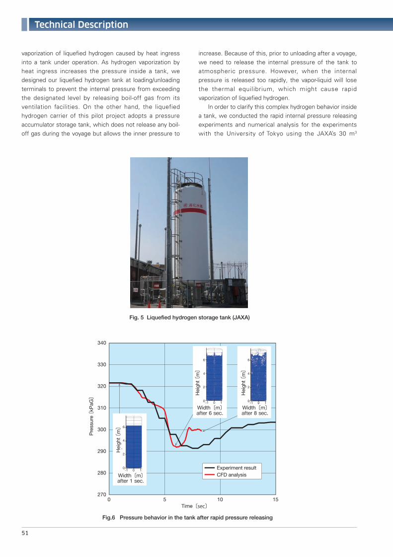
and then we performed ventilation analysis for the enclosed space using CFD. Ventilation flow analysis for room-temperature air in a cargo machinery room is shown in Figure 3, and hydrogen behavior analysis for when cryogenic hydrogen gas leaks from 5 mm2 hole is shown in Figure 4. In Figure 3, each color of the lines represents the air residual time from the inlet port to the exhaust port, which shows that the air taken in from the inlet was
ventilated smoothly. Figure 4 shows that the hydrogen leakage (colored light blue) from a pipe connection quickly reached the exhaust port.(ii) Analysis of hydrogen behavior in liquefied hydrogen
storage tank by rapid pressure release While we have designed a liquefied hydrogen storage tank adopting state-of-the-art thermal insulation technology, it is impossible to completely prevent the
16°C
-40°C
Temperature
30°C
-40°C
Temperature
Kawasaki Technical Review No.182
February 2021
吸気口吸気口
排気口排気口Exhaust port
Inlet port
Exhaust port
Leak hydrogen
Inlet port
Fig. 3 Ventilation flow analysis for cargo machinery room
Fig. 4 Hydrogen leakage behavior analysis for cargo machinery room
Fig. 2 Dispersion tests
(a) Vapor cloud distribution of liquefied hydrogen
(d) Temperature distribution of LNG(c) Vapor cloud distribution of LNG
(b) Temperature distribution of liquefied hydrogen
技術07E_210113.indd 50 2021/02/02 11:17:11
Technical Description
51
vaporization of liquefied hydrogen caused by heat ingress into a tank under operation. As hydrogen vaporization by heat ingress increases the pressure inside a tank, we designed our liquefied hydrogen tank at loading/unloading terminals to prevent the internal pressure from exceeding the designated level by releasing boil-off gas from its ventilation facilities. On the other hand, the liquefied hydrogen carrier of this pilot project adopts a pressure accumulator storage tank, which does not release any boil-off gas during the voyage but allows the inner pressure to
increase. Because of this, prior to unloading after a voyage, we need to release the internal pressure of the tank to atmospheric pressure. However, when the internal pressure is released too rapidly, the vapor-liquid will lose the thermal equilibrium, which might cause rapid vaporization of liquefied hydrogen. In order to clarify this complex hydrogen behavior inside a tank, we conducted the rapid internal pressure releasing experiments and numerical analysis for the experiments with the University of Tokyo using the JAXA’s 30 m3
Time〔sec〕
Experiment resultCFD analysisWidth〔m〕
after 1 sec.
Pre
ssur
e 〔kP
aG〕
Hei
ght 〔
m〕
Hei
ght 〔
m〕
Hei
ght 〔
m〕
280
270
290
300
310
320
330
340
0 5 10 15
Width〔m〕after 6 sec.
Width〔m〕after 8 sec.
-1 10
-1 10 -1 10
0
2
4
6
0
2
4
6
0
2
4
6
Fig.6 Pressure behavior in the tank after rapid pressure releasing
Fig. 5 Liquefied hydrogen storage tank (JAXA)
技術07E_210113.indd 51 2021/02/02 11:17:15
52
Conclusion
2020 and beyond, the demonstrations of the loading/unloading and marine transportation of liquefied hydrogen between the Hastings port in Australia and Kobe airport island in Japan, will have started, and we are working to complete all demonstrations without any accidents . Finally, we would like to acknowledge the technical team of Shell Japan Ltd. for their enormous contributions to the safety assessments for this project.
Reference
1) S. Unno, Y. Takaoka, S. Kamiya, A study on dispersion resulting from liquefied hydrogen spilling, ICHS 2015
2) IMO MSC.420 (97), Interim recommendations for carriage of liquefied hydrogen in bulk
3) IMO CCC3/INF.20, Safety requirements for carriage of liquefied hydrogen in bulk
4) K. Tani, T. Himeno et al, Prediction of pressure reduction rate in 30m3 liquid hydrogen tank based on experimental and numerical analysis, ICHS 2019
cylindrical liquefied hydrogen storage tanks, and we are examining the changes in the pressure and temperature inside the tank and analyzing how gas is produced from the liquid phase 4). Figure 5 is an image of the storage tank under analysis. Figure 6 is sample data of the experiments and analysis on the pressure change inside the tank during rapid pressure release. From these results, after a rapid pressure releasing operation, we observed a pressure increasing phenomena, but such pressure change was relatively mild. This phenomena is deeply related to the behavior of a gas phase that is generated in a liquid phase, we are now developing more advanced analysis models as shown in Figure 6.
(3) HSE management system In the overseas energy and chemical plant industory , it is becoming standard for product development to be conducted based on a systematic management system called HSE (Health, Safety and Environment), which is an integrated concepts that includes occupational safety , health and environmental consciousness. HSE requires that risk assessments be conducted voluntarily by manufacturers and they need to establish own management systems to carry out and incorporate such assessments in an effective manner. More and more industries are applying HSE and application of HSE is being a tendering requirement. HSE-based management is becoming the global standard. CO2-free Hydrogen Energy Supply-chain Technology Research Association (HySTRA), which is carrying out the Japan-Australia pilot project, established the Policy on Health, Safety, Security and Environment (HSSE Effort) at its foundation, which incorporates security into the HSE concept. Based on this policy, Kawasaki has developed HSSE plans to specify the activities in our Kobe Works and Harima Works, which design and manufacture the liquefied hydrogen carriers and the liquefied hydrogen storage tanks. We are now implementing the activities specified in these HSSE management processes for the demonstration phase, based on the Plan-Do-Check-Action (PDCA) cycle. Based on this project’s plans, we are establishing our common HSE plan and management system that is also applicable to other projects. We are aiming for a more versatile, universal standard system in combination common and project-specific elements, and we will continue to make improvements while taking into account the results of actual projects.
Kawasaki Technical Review No.182
February 2021
PMP (Project Management Professional)Katsuhiro KanbeHSE & Standard Promotion Department, Hydrogen Project Development Center,Corporate Technology Division
Doctor of Engineering,P.E.Jp (Mechanical Engineering)Shoji KamiyaTechnology Development Department,Hydrogen Project Development Center,Corporate Technology Division
Atsushi KomuraShip & Offshore Structure Company
Professional Engineer (Information Engineering)Toshihisa IshigakiCryogenic Storage System Department, Industrial Plant Engineering Group,Plant Engineering Business Division,Energy System & Plant Engineering Company
技術07E_210113.indd 52 2021/02/02 11:17:20
![Featured Article No. 1 Hydrogen Society has come: … Society has come: Beginning of the New Age of Hydrogen [Featured Article No. 2] ~Talking with NEDO Representative Office in …](https://img.pdfslide.us/doc/110x75/5ab82ff77f8b9a684c8c854a/featured-article-no-1-hydrogen-society-has-come-society-has-come-beginning.jpg)