Embed Size (px)
Citation preview
16th IMEKO TC10 Conference
“Testing, Diagnostics & Inspection as a comprehensive value chain for Quality & Safety”
Berlin, Germany, on September 3-4, 2019
Product quality and cutting tool analysis for
micro-milling of ceramics
L Móricz1, Zs. J. Viharos2,3, A. Németh4, A. Szépligeti4
1University of Pannonia, Faculty of Engineering, Mechatronic Education and Research Institute H-
8900, Gasparich Márk str. 18/A., Zalaegerszeg, Hungary 2Centre of Excellence in Production Informatics and Control, Institute for Computer Science and
Control of the Hungarian Academy of Sciences (MTA SZTAKI), H-1111, Kende str. 13-17.,
Budapest, Hungary 3John von Neumann University, H-6000, Izsáki str. 10, Kecskemét, Hungary
4AQ Anton Kft., H-8900, Sport str. 16., Zalaegerszeg, Hungary
Abstract – Based on their favourable mechanical
features, applications of ceramics are continuously
spreading in industrial environment. Such a good
feature is their resistance against heat shock, so,
currently they are applied e.g. as coating material for
gas turbines. The main aims of the paper to follow the
wearing process of the micro-milling tool during
machining of ceramics and to compare it against the
geometrical changes of the machined ceramic
workpiece, applied as a special monitoring technique.
Keywords: cutting of ceramics, regular cutting edge
geometry, micro-milling, product quality, tool wear
I. INTRODUCTION
Machining of rigid materials with regular cutting edge
geometry is one of the main trends in the 21th century.
Ceramics are such rigid materials that are employed more
and more widely as raw materials thanks to their high
hardness and thermal resistance [1][2]. There are various
options for machining them, e.g. using water, laser or
abrasive grinding [3][4][5], however, their high costs
and complex setups are important drawbacks of these
technologies. Therefore, the machining of ceramics with a
classical, regular cutting edge geometry is still a promising
solution, however, considering the relative quick wearing
process of the cutting tool without an appropriate
technological optimisation, this methodology will be
economically not acceptable.
Optimizing a technology is typically a multicriteria
assignment, like here, the main aim is to find the smallest
production cycle time, and in the same time the tool life
has to be maximal, too. The tool wear state serves with
information about the actual wearing stage of the tool.
Bian et al. [6] used ultra-miniature diamond coated
tools to mill fully sintered ZrO2. Wear of the tool was
described by three stages:
1. Early coating delamination;
2. Extended coating delamination with slight wear of the
exposed cutting edge;
3. Severe wear of the tool blank.
Romanus et al. [7] analysed the tool wearing process
and the resulted surface quality during cutting of also ZrO2
by diamond and cBN coated milling tools. They observed
the same three stages of the wearing.
Bian et al. described experimental results in another
publication [8] using WC milling tool coated by different
sizes of diamond grains with the aim for analysing the
peeling process of the diamond coating. They concluded
that when the machining in the classical “X-Y” direction
the cutting force is significantly smaller as in the “Z”
direction. The reason for that is, in case of “X-Y” they
managed to keep the cutting in the plastic deformation area,
while in the “Z” direction the brittle area was dominating.
They identified also that with the increase of the feed per
tooth and axial cutting depth the cutting force will grow
significantly.
Based on the literature review one can identify that the
research on cutting of hard and brittle materials by
advanced tools is still in an early stage, especially as far it
concerns micro scale applications. Based on the analysis
conducted, the main challenges can be summarized as
follows:
a) availability of ultra-miniature tools having
appropriate cutting edge geometry to ensure
proper compression/tensile stress distribution in
16th IMEKO TC10 Conference
“Testing, Diagnostics & Inspection as a comprehensive value chain for Quality & Safety”
Berlin, Germany, on September 3-4, 2019
the chip zone;
b) appropriate tool stiffness and sufficient wear
resistance;
c) identification of suitable cutting parameters to
ensure ductile material removal and damage-free
machined surfaces. [7]
The main aims of the current paper are - continuing a
previous research - to follow the wearing process of the
micro-milling tool during machining of ceramics and to
compare it against the geometrical changes of the
machined ceramic workpiece, applied as a special
monitoring technique.
II. FACTORS INFLUENCING THE CUTTING TOOL
LIFE
There are plenty of technological parameters that
influence the micro-milling of ceramics. However, the
literature shows that the most influencing parameters are
the following:
Technological parameters
• axial cutting depth
• radial cutting depth
• cutting speed
• feed(rate)
• tool tilt angle
Geometry of cutting tool
• flank angle
• rake angle
• number of teeth
Tool material, coating
• basic tool material
• type of coating
• thickness of coating
• grain size
• number of coating layers
Type of cooling
Other parameters
• combined shaping technology
An important assignment for the cutting process with
regular geometry tool is to keep the cutting in plastic
deformation area instead of in brittle area [8].
K. Ueda and his colleagues cut plenty of ceramics
materials to find solution for this question, and they found
that materials that have high fracture toughness can be cut
easier in plastic deformation area with optimal cutting
speed and feed [8]. However, with low fracture toughness
they did not find a parameter combination that can cut in
the ductile deformation zone.
The other author of the mentioned publication who
conducts some research into the ductile-brittle range in
shaping method is Muhammed A, who tried to find what
those cutting parameters are, and how they influence the
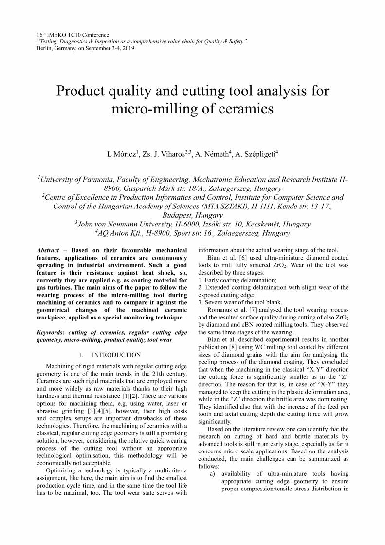
ductile range [9]. It was found that there are critical
parameters belonging to the cutting depth and feed values
which affects the chip-removal mechanism. These results
are summarized in Figure 1.
Fig. 1. Critical value of feed-depth to reach the plastic
deformation range [9]
During their experiments it was found that there is a
critical value of cutting depth and feed, where the analysed
material can be shaped in the ductile removal area. Under
a certain cutting depth, the value of feed can be increased
without the removal of the cutting mechanism from the
brittle area. This means that the plastic deformation
strongly depends on the value of the cutting depth.
Differences should be considered between two types of
cutting depths, axial cutting depth and radial cutting depth
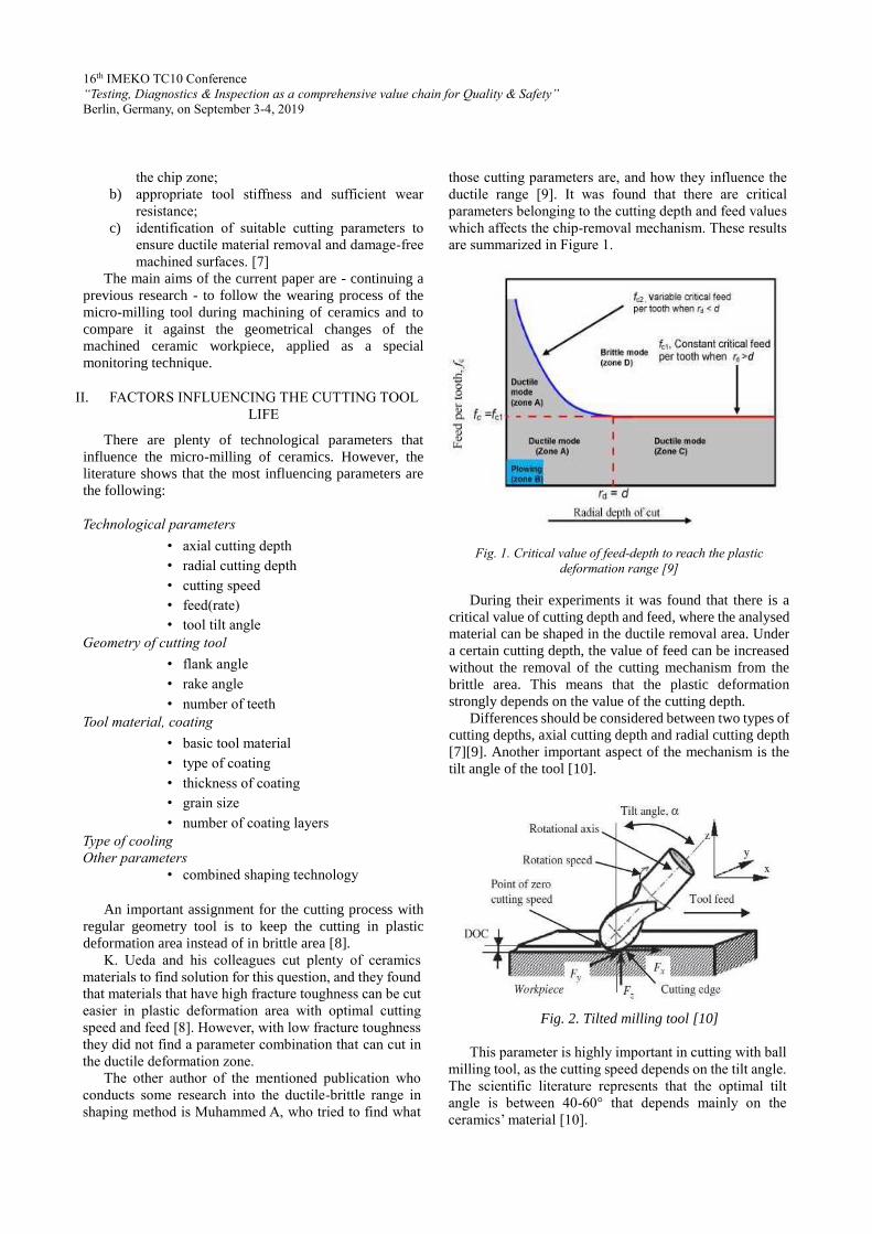
[7][9]. Another important aspect of the mechanism is the
tilt angle of the tool [10].
Fig. 2. Tilted milling tool [10]
This parameter is highly important in cutting with ball
milling tool, as the cutting speed depends on the tilt angle.
The scientific literature represents that the optimal tilt
angle is between 40-60° that depends mainly on the
ceramics’ material [10].
16th IMEKO TC10 Conference
“Testing, Diagnostics & Inspection as a comprehensive value chain for Quality & Safety”
Berlin, Germany, on September 3-4, 2019
A combined technology is a further interesting method
for enhancing the lifetime of a cutting tool: Toru et al. [11]
combined the conventional cutting technology with laser
technology. J. Feng et al. [12] performed machining with
irregular cutting tool geometry while they made
conclusions on the cutting tool’s wear based on cutting
force and vibration measurements. Xiaohong and his
colleagues [13] preformed similar research with laser-
assisted cutting. They found that the laser has a strong
influence on the grinding characteristics. The normal and
tangential grinding forces for laser assisted grinding is 15%
lower than that in the conventional grinding method.
In previous researches of the authors the linear,
Taguchi based Design of Experiment (DoE) were applied
to analyse the effect of the varying technological
parameters on the tool wearing [14]. The results served
with a quasi (linear) optimal technology concerning the
maximisation of material removal speed; however, the
analysis of the wearing process is an open issue, because a
novel indirect measurement could be applied before [15].
The current paper goes beyond the previously applied
methods, because the complete wearing behaviour of the
tool is described.
III. EXPERIMENTS WITH MACHINING USING
SMALL PITCH ANGLES
Micro-milling tools were applied for the ceramics
cutting experiments.
Fig.3. Tool geometry and angles
According to the available literature, the cutting edge
and the flank edge (Fig. 3.) are loaded on the highest level
during such machining [7][8].
Parameters of the milling machine
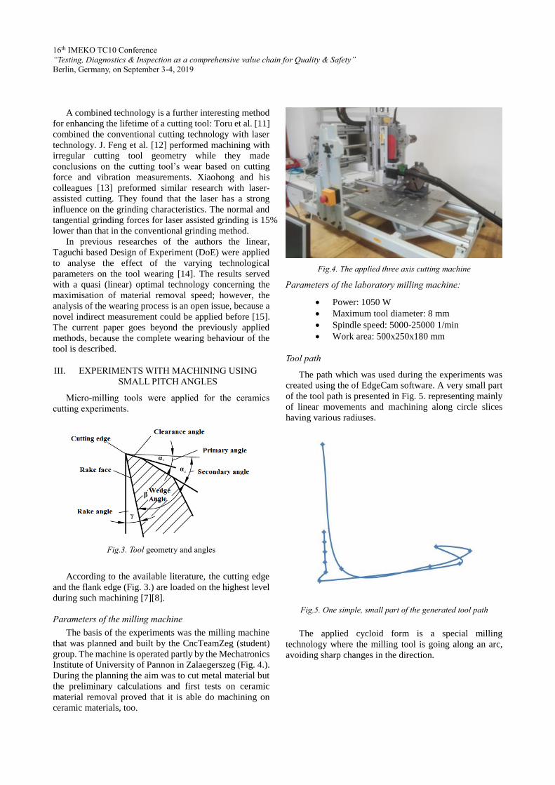
The basis of the experiments was the milling machine
that was planned and built by the CncTeamZeg (student)
group. The machine is operated partly by the Mechatronics
Institute of University of Pannon in Zalaegerszeg (Fig. 4.).
During the planning the aim was to cut metal material but
the preliminary calculations and first tests on ceramic
material removal proved that it is able do machining on
ceramic materials, too.
Fig.4. The applied three axis cutting machine
Parameters of the laboratory milling machine:
Power: 1050 W
Maximum tool diameter: 8 mm
Spindle speed: 5000-25000 1/min
Work area: 500x250x180 mm
Tool path
The path which was used during the experiments was
created using the of EdgeCam software. A very small part
of the tool path is presented in Fig. 5. representing mainly
of linear movements and machining along circle slices
having various radiuses.
Fig.5. One simple, small part of the generated tool path
The applied cycloid form is a special milling
technology where the milling tool is going along an arc,
avoiding sharp changes in the direction.
16th IMEKO TC10 Conference
“Testing, Diagnostics & Inspection as a comprehensive value chain for Quality & Safety”
Berlin, Germany, on September 3-4, 2019
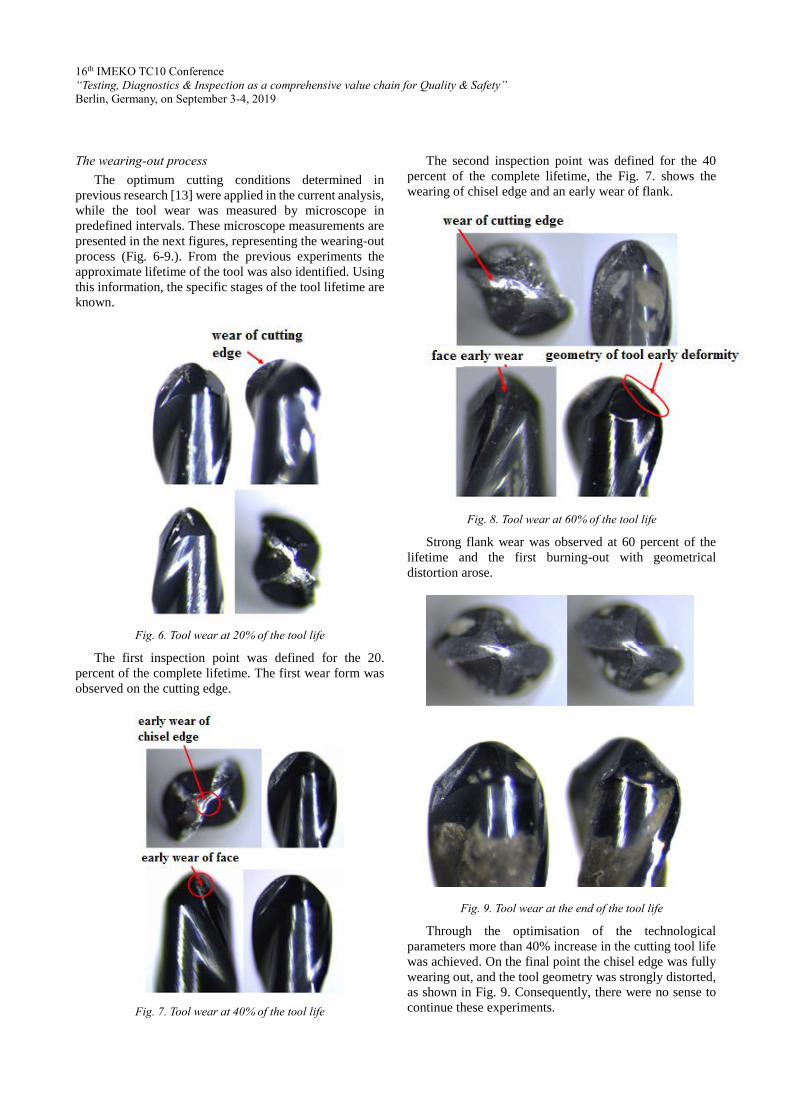
The wearing-out process
The optimum cutting conditions determined in
previous research [13] were applied in the current analysis,
while the tool wear was measured by microscope in
predefined intervals. These microscope measurements are
presented in the next figures, representing the wearing-out
process (Fig. 6-9.). From the previous experiments the
approximate lifetime of the tool was also identified. Using
this information, the specific stages of the tool lifetime are
known.
Fig. 6. Tool wear at 20% of the tool life
The first inspection point was defined for the 20.
percent of the complete lifetime. The first wear form was
observed on the cutting edge.
Fig. 7. Tool wear at 40% of the tool life
The second inspection point was defined for the 40
percent of the complete lifetime, the Fig. 7. shows the
wearing of chisel edge and an early wear of flank.
Fig. 8. Tool wear at 60% of the tool life
Strong flank wear was observed at 60 percent of the
lifetime and the first burning-out with geometrical
distortion arose.
Fig. 9. Tool wear at the end of the tool life
Through the optimisation of the technological
parameters more than 40% increase in the cutting tool life
was achieved. On the final point the chisel edge was fully
wearing out, and the tool geometry was strongly distorted,
as shown in Fig. 9. Consequently, there were no sense to
continue these experiments.
16th IMEKO TC10 Conference
“Testing, Diagnostics & Inspection as a comprehensive value chain for Quality & Safety”
Berlin, Germany, on September 3-4, 2019
In the current paper only the cutting tool wearing forms
were examined together with the specification in which
section of tool lifetime they appear. To give nominal,
directly measured values for tool degradation will be one
of the next steps in the research.
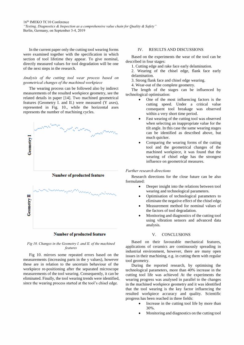
Analysis of the cutting tool wear process based on
geometrical changes of the machined workpiece
The wearing process can be followed also by indirect
measurements of the resulted workpiece geometry, see the
related details in paper [14]. Two machined geometrical
features (Geometry I. and II.) were measured (Y axes),
represented in Fig. 10., while the horizontal axes
represents the number of machining cycles.
Fig 10. Changes in the Geometry I. and II. of the machined
features
Fig 10. mirrors some repeated errors based on the
measurements (increasing parts in the y values), however
these are in relation to the uncertain behaviour of the
workpiece re-positioning after the separated microscope
measurements of the tool wearing. Consequently, it can be
eliminated. Finally, the tool wearing trends were identified,
since the wearing process started at the tool’s chisel edge.
IV. RESULTS AND DISCUSSIONS
Based on the experiments the wear of the tool can be
described in four stages:
1. Cutting edge and rake face early delamination.
2. Wearing of the chisel edge, flank face early
delamination.
3. Strong flank face and chisel edge wearing.
4. Wear-out of the complete geometry.
The length of the stages can be influenced by
technological optimisation:
One of the most influencing factors is the
cutting speed. Under a critical value
consequent tool breakage was observed
within a very short time period.
Fast wearing of the cutting tool was observed
when selecting an inappropriate value for the
tilt angle. In this case the same wearing stages
can be identified as described above, but
much quicker.
Comparing the wearing forms of the cutting
tool and the geometrical changes of the
machined workpiece, it was found that the
wearing of chisel edge has the strongest
influence on geometrical measures.
Further research directions
Research directions for the close future can be also
formulated:
Deeper insight into the relations between tool
wearing and technological parameters.
Optimisation of technological parameters to
eliminate the negative effect of the chisel edge.
Measurement method for nominal values of
the factors of tool degradation.
Monitoring and diagnostics of the cutting tool
using vibration sensors and advanced data
analysis.
V. CONCLUSIONS
Based on their favourable mechanical features,
applications of ceramics are continuously spreading in
industrial environment, however, there are many open
issues in their machining, e.g. in cutting them with regular
tool geometry.
During the reported research, by optimising the
technological parameters, more than 40% increase in the
cutting tool life was achieved At the experiments the
wearing progress was analysed in parallel to the changes
in the machined workpiece geometry and it was identified
that the tool wearing is the key factor influencing the
resulted workpiece accuracy and quality. Scientific
progress has been reached in three fields:
Increase in the cutting tool life by more than
30%.
Monitoring and diagnostics on the cutting tool
16th IMEKO TC10 Conference
“Testing, Diagnostics & Inspection as a comprehensive value chain for Quality & Safety”
Berlin, Germany, on September 3-4, 2019
wear directly and indirectly, and comparison
of them.
Analysis of the cutting tool also after the
damage and wear-out of the tool coating.
The reported research allowed to improve and stabilise
the cutting of ceramics significantly by micro-milling with
regular tool geometry.
VI. ACKNOWLEDGMENTS
First of all, thanks have to be expressed to the AQ
Anton Kft., serving with materials, equipment, challenges,
experts any many other resources enabling and supporting
the research. The research in this paper was partly
supported by the European Commission through the
H2020 project EPIC (https://www.centre-epic.eu/) under
grant No. 739592 and by the Hungarian ED_18-2-2018-
0006 grant on a "Research on prime exploitation of the
potential provided by the industrial digitalisation".
REFERENCES
[1] Peter, J.: Modern gas turbine systems, High Efficiency, Low Emission, Fuel Flexible Power Generation. Woodhead Publishing Series in Energy: No 20, 2013., pp. 8-38.
[2] Móricz, L.; Viharos, Zs. J.: Trends on applications and feature improvements of ceramics, Manufacturing 2015 Conference, Budapest University of Technology and Economics, Vol. 15, No., 2, 2015, pp. 93-98
[3] Lingfei, J.; Yinzhou, Y.; Yong, B.; Yijian, J.: Crack-free cutting of thick and dense ceramics with CO2 laser by single-pass process. Optics and Lasers in Engineering 46., 2008, pp. 785-790.
[4] Jiyue, Z.; Thomas, J. K.: An erosion model for abrasive waterjet milling of polycrystalline ceramics. Wear 199 1996, pp. 275-282.
[5] Móricz, L.; Viharos, Zs. J.: Optimization of ceramic
cutting, and trends of machinability, 17th International
Conference on Energetics-Electrical Engineering - 26th
International Conference on Computers and Educations,
Hungarian Technical Scientific, Society of Transylvania, 6-
9 October, 2016, pp. 105-110.
[6] Bian, R.; Ferraris, E.; Qian, J., Reynaerts, D.; Li, L.;
He, N.: Micromilling of fully sintered ZrO2 ceramics with
diamond coated end mills, Conf on Prec Eng - Key Eng
Mater, 523(524), 2012, pp. 87-92.
[7] Heleen, R.; Eleonora, F.; Jan B.; Dominiek, R.; Bert, L.:
Micromilling of sintered ZrO2 ceramic via CBN and dia-
mond coated tools, Procedia CIRP 14, 2014, pp. 371 – 376. [8] Ueda, K.; Sugita, T.; Hiraga, H.:A J-integral Approach to
Material Removal Mechanisms in Microcutting of Ceramics, CIRP Annals - Manufacturing Technology 40, 1991, pp. 61–64.
[9] Muhammad, A.; Mustafizur, R.; Wong, Y. S.: Analytical model to determine the critical conditions for the modes of material removal in the milling process of brittle material. Journal of Materials Processing Technology 212, 2012, pp. 1925– 1933.
[10] Kevin, F.; Zhi, W.; Takash,i M.; Yong, H.: Effect of tilt angle on cutting regime transition in glass micromilling. International Journal of Machine Tools & Manufacture 49, 2009, pp. 315–324.
[11] Toru, K.; Ogasahar, T.; Sugita, N.; Mitsuishi, M.: Ultraviolet-laser-assisted precision cutting of yttria-stabilized tetragonal zirconia polycrystal, Journal of Materials Processing Technology 214, pp. 267– 275.
[12] Fen J, Kim B S, Shih A, Ni J 2009 Tool wear monitoring for micro-end grinding of ceramic materials. Journal of Materials Processing Technology 209, pp. 5110–5116.
[13] Xiaohong Z, Zhicheng Z, Zhaohui D, Si L, Qiaoping W,
Zhongxiong K 2019 Precision grinding of silicon nitride
ceramic with laser macro-structured diamond wheels Op-
tics and Laser Technology 109, pp 418–428.
[14] Móricz, L.; Viharos, Zs. J.; Németh, A.; Szépligeti, A.: Efficient Ceramics Manufacturing through Tool Path and Machining Parameter Optimisation, 15th IMEKO TC10 Workshop on Technical Diagnostics, Budapest, Hungary, June 6-7., 2017, pp. 143-148.
[15] Móricz, L.; Viharos, Zs. J.; Németh, A.; Szépligeti, A.: Indirect measurement and diagnostics of the tool wear for ceramics micro-milling optimisation, XXII IMEKO World Congress, September 3-6, Belfast, United Kingdom, Journal of Physics: Conference Series (JPCS), Vol. 1065, 2018., paper ID: IMEKO-OR-135.