Embed Size (px)
Citation preview

Rev. 06 12/06
Product Guide

2www.stucki.com
1. Scope ..............................................................5
2. Truck and Body Side Bearings .....................6 General Requirements ..................................6 Extended Travel CCSB ...............................7 Extended Travel RetroXT CCSB ...............10 Extended Travel Upgrade CCSB...............14 Standard Travel CCSB ..............................17 Roller Side Bearings..................................28 Plate and Wedge .......................................30 Yard Inspection ............................................31 General Inspection ....................................31 Setup Height..............................................34 Single Unit Cars ......................................34 Articulated Cars ......................................38 RetroXT LP, LPC, and SP .......................39 Shop Inspection...........................................43 General Inspection ....................................43 Setup Height..............................................48 Visual Height Inspection .........................52
3. Resilient Friction Elements .........................56 Product Reference Table .............................57 Products Barber Trucks ............................................58 ASF Trucks ................................................59 Wear Indicator .............................................61 Yard Inspection ............................................62 Shop Inspection...........................................64
Table of Contents

3www.stucki.com
4. Hydraulic Stabilizers .................................. 67 Products .................................................... 67 Yard and Shop Inspection ......................... 69
5. International Products ............................... 74 Side Bearings ............................................ 75 Australia, New Zealand and Malaysia ..... 75 Europe ..................................................... 86 South America ......................................... 86 Resilient Friction Elements ........................ 89 Australia and New Zealand ..................... 89
6. Brake Beams .............................................. 93 Products .................................................... 94 Inspection .................................................. 95 Reversing the Brake Beam ....................... 96 Replacing the Head ................................... 98
7. Reconditioning Services ........................... 99 Draft Gear.................................................. 99 Truck Components .................................. 106 Other Components .................................. 106
Product Index ........................................... 108
Tabel of ContentsTable of Contents
4www.stucki.com
A. Stucki Company, a division of Hansen, Inc., is a worldwide leader in freight car dynamic control products. Reconditioning and repair services are provided through two sister companies; Independent Draft Gear and American Industries.

5www.stucki.com
1. Scope
This pocket guide provides recommended procedures for yard and repair shop inspection of products manufactured and reconditioned by A. Stucki Company, including truck side bearings, body side bearings, resilient friction elements, hydraulic stabilizers, brake beams, and draft gears.
This guide is intended primarily for product inspection and maintenance guidance, and does not cover initial product installation procedures. Drawings and installation instructions for each of Stucki’s products may be obtained from the A. Stucki Company online catalog, located on the Stucki Web Site (www.stucki.com), or by calling 412.771.7300.

Sid
e Bearin
gs
Sid
e Bearin
gs
6www.stucki.com
2. Truck and Body Side Bearings
General Requirements
The tools required for inspection include a set of calipers, a measuring tape, and a flashlight.

7
Sid
e B
eari
ng
s
www.stucki.com
Fig. 2.1 — Shear Side Bearing (SSB)
Note: Replacement cages are ordered by specifying preload, i.e. 6000XT Cage, where 6000 = preload, XT for extended travel.
Sid
e Bearin
gs
Sid
e Bearin
gs
8www.stucki.com
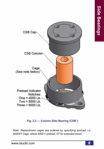
Note: Replacement cages are ordered by specifying preload, i.e. 6000XT Cage, where 6000 = preload, XT for extended travel.
Fig. 2.2 — Column Side Bearing (CSB)
9
Sid
e B
eari
ng
s
www.stucki.com
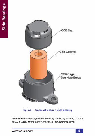
Fig. 2.3 — Compact Column Side Bearing
Note: Replacement cages are ordered by specifying preload, i.e. CCB 6000XT Cage, where 6000 = preload, XT for extended travel.

Sid
e Bearin
gs
Sid
e Bearin
gs
10www.stucki.com
Fig. 2.4 — RetroXT LP Bolt-On, 4500 Lb. Preload

11
Sid
e B
eari
ng
s
www.stucki.com
Fig. 2.5 — RetroXT LP Drop-In, 4500 Lb. Preload
For monocast or welded bolster pocket, approximately 4-1/4" x 9-1/4", low profile design.

Sid
e Bearin
gs
Sid
e Bearin
gs
12www.stucki.com
Fig. 2.6 — RetroXT LPC Drop-In, 4500 Lb. Preload
For monocast or welded bolster pocket, approximately 3-1/2" x 8-1/4", low profile design.
13
Sid
e B
eari
ng
s
www.stucki.com
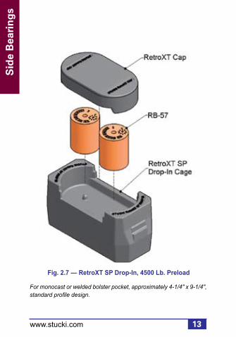
Fig. 2.7 — RetroXT SP Drop-In, 4500 Lb. Preload
For monocast or welded bolster pocket, approximately 4-1/4" x 9-1/4", standard profile design.
Sid
e Bearin
gs
Sid
e Bearin
gs
14www.stucki.com
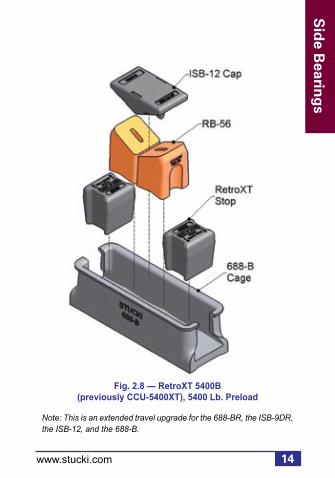
Fig. 2.8 — RetroXT 5400B (previously CCU-5400XT), 5400 Lb. Preload
Note: This is an extended travel upgrade for the 688-BR, the ISB-9DR, the ISB-12, and the 688-B.

15
Sid
e B
eari
ng
s
www.stucki.com
Fig. 2.9 — RetroXT 5400C, 5400 Lb. Preload
Note: This an extended travel upgrade for the 656-CR, the 656-CRH, and the 656-C.

Sid
e Bearin
gs
Sid
e Bearin
gs
16www.stucki.com
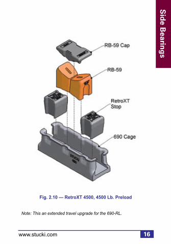
Fig. 2.10 — RetroXT 4500, 4500 Lb. Preload
Note: This an extended travel upgrade for the 690-RL.

17
Sid
e B
eari
ng
s
www.stucki.com
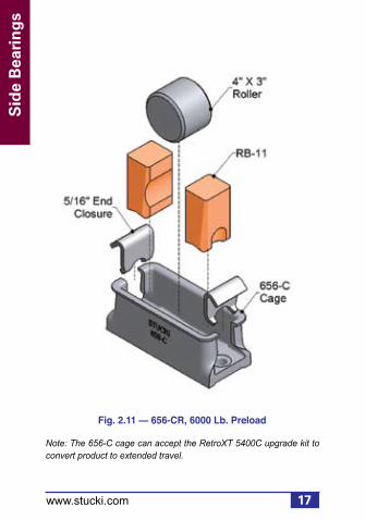
Fig. 2.11 — 656-CR, 6000 Lb. Preload
Note: The 656-C cage can accept the RetroXT 5400C upgrade kit to convert product to extended travel.
Sid
e Bearin
gs
Sid
e Bearin
gs
18www.stucki.com
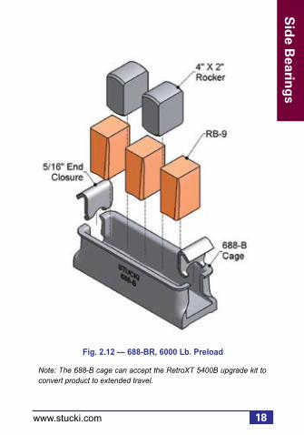
Fig. 2.12 — 688-BR, 6000 Lb. Preload
Note: The 688-B cage can accept the RetroXT 5400B upgrade kit to convert product to extended travel.

19
Sid
e B
eari
ng
s
www.stucki.com
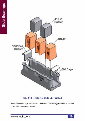
Fig. 2.13 — 690-RL, 3600 Lb. Preload
Note: The 690 cage can accept the RetroXT 4500 upgrade kit to convert product to extended travel.

Sid
e Bearin
gs
Sid
e Bearin
gs
20www.stucki.com
Fig. 2.14 — 656-CRH, 5400 Lb. Preload
Note: The 656-C cage can accept the RetroXT 5400C upgrade kit to convert product to extended travel.

21
Sid
e B
eari
ng
s
www.stucki.com
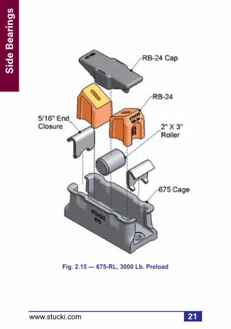
Fig. 2.15 — 675-RL, 3000 Lb. Preload

Sid
e Bearin
gs
Sid
e Bearin
gs
22www.stucki.com
Fig. 2.16 — 685-RM, 4500 Lb. Preload

23
Sid
e B
eari
ng
s
www.stucki.com
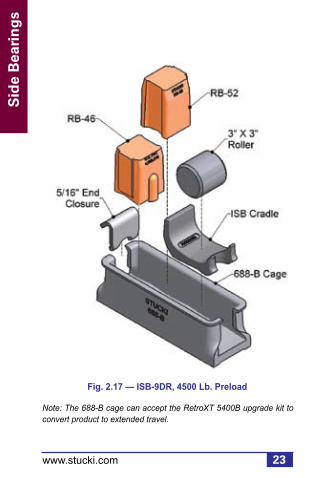
Fig. 2.17 — ISB-9DR, 4500 Lb. Preload
Note: The 688-B cage can accept the RetroXT 5400B upgrade kit to convert product to extended travel.
Sid
e Bearin
gs
Sid
e Bearin
gs
24www.stucki.com
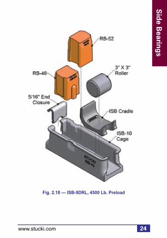
Fig. 2.18 — ISB-9DRL, 4500 Lb. Preload

25
Sid
e B
eari
ng
s
www.stucki.com
Fig. 2.19 — ISB-10, 4500 Lb. Preload

Sid
e Bearin
gs
Sid
e Bearin
gs
26www.stucki.com
Fig. 2.20 — ISB-12, 5400 Lb. Preload
Note: The 688-B cage can accept the RetroXT 5400B upgrade kit to convert product to extended travel.

27
Sid
e B
eari
ng
s
www.stucki.com
Fig. 2.21 — 656-SLB, No Preload

Sid
e Bearin
gs
Sid
e Bearin
gs
28www.stucki.com
Fig. 2.22 — 656-C
Note: The 656-C cage can accept the RetroXT 5400C upgrade kit to convert product to extended travel.

29
Sid
e B
eari
ng
s
www.stucki.com
Fig. 2.23 — 688-B
Note: The 688-B cage can accept the RetroXT 5400B upgrade kit to convert product to extended travel.

Sid
e Bearin
gs
Sid
e Bearin
gs
30www.stucki.com
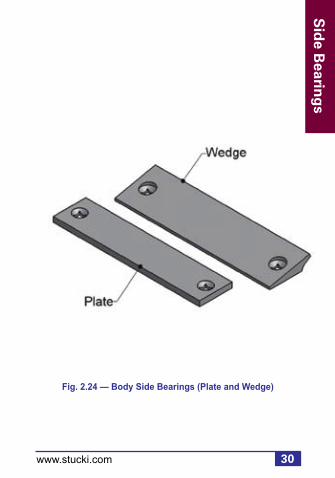
Fig. 2.24 — Body Side Bearings (Plate and Wedge)
31
Sid
e B
eari
ng
s
www.stucki.com
Yard Inspection
General Inspection
Physically identify the side bearing model from the illustrations in Section 2. Be sure all components for that model are present and in the correct orientation. Missing or damaged components should be replaced prior to placing the car back into service.
Cage: Inspect cages for cracks, flaws, or unusual deformation. The cage must be securely fastened to the truck bolster.
Body Side Bearing: Plates or wedges must be securely tightened and the surface must be smooth. Fastener heads must not protrude below the wear plate surface.

Sid
e Bearin
gs
Sid
e Bearin
gs
32www.stucki.com
End Closure: End closures must be in place and not broken. ISB models have only one end closure.
Resilient Element: Resilient elements should be checked for evidence of overheating. Resilient urethane can be permanently damaged at high temperatures brought about by severe truck hunting or exposure to extreme temperatures generated by improperly used thaw sheds.
If any signs of heat damage exist (such as severe cracking, bulging, or deformation), replace the urethane blocks. Note that the 688-BR and 690-RL cars need not be shopped for repairs for a single block having a missing top portion. The side bearing will function adequately with only 2 of the 3 blocks contacting. Replace the defective block when the car is next shopped for required maintenance or other repairs. Bad-order the car if two or more block tops are missing.

33
Sid
e B
eari
ng
s
www.stucki.com
Rocker: Rockers may not always be seated on the bottom of the cage, and clearance should not be used as a setup height criterion. While in service, vertical movement may occur. This has no effect on the performance of the side bearing. Rockers contact the body side bearing as the car rocks or leans. Light wear of the upper and lower surfaces of the
rockers is normal.

Sid
e Bearin
gs
Sid
e Bearin
gs
34www.stucki.com
Yard Inspection: Vertical Setup Height
Figure 2.25 summarizes the measurement ranges allowable for yard inspection. For articulated cars, see page 38. For RetroXT LP, LPC, and SP Side Bearings, see pages 39-42.
For yard inspection, the vertical distance between the body side bearing wear plate (or wedge) and the truck bolster surface to which the side bearing cage is mounted must be between 4-15/16" and 5-3/16", as illustrated in figure 2.25. This measurement assumes the car is empty and is positioned on reasonably level track. Be alert to the possibility of encountering shims under side bearing cages. This practice should be avoided, but when present, measurement must reference to top of shims.

35
Sid
e B
eari
ng
s
www.stucki.com
Fig. 2.25 — Vertical Setup Height, Inspection Tolerances for Standard Setup Height Applications
NEW ELASTOMERIC CENTERBOWL LINER, OR SINGLE SOLID CENTER PLATE LUBE DISC(Ref: Stucki Service Bulletin RSB9501)
METAL TO METAL CENTERBOWL CONTACT
YARD INSPECTION5-1/16" ± 1/8"
Note: Does not apply to intermodal articulated cars or RetroXT LP, LPC, or SP side bearings. See page 38 for articulated cars, and page 39 for RetroXT Side Bearings.
Sum of the Pairs Method Add the two side bearing heights at the end of each car. The sum must be between 9-7/8" and 10-3/8". No individual space should be less than 4-15/16".
Note: 1) Car on reasonably level track 2) Car is empty
SHOP SET UP5-1/8" ± 1/16"
SHOP SET UP5-1/16" ± 1/16"

Sid
e Bearin
gs
Sid
e Bearin
gs
36www.stucki.com
Fig. 2.26 — Vertical Setup Height, Yard Inspection
5-1/16" ± 1/8"

37
Sid
e B
eari
ng
s
www.stucki.com
If reasonably level track conditions cannot be obtained, the Sum of the Pairs method can be used by adding the measurements for the two side bearings on each truck. The sum of the measurements may be as low as 9-7/8” or as high as 10-3/8” for all standard and extended travel side bearings on single unit, stand-alone cars. No individual space should be less than 4-15/16”.
If the above tolerances are exceeded, and the car is empty, it must be shopped and the car body side bearing shims adjusted to obtain the specified setup height. (See Shop Inspection: Vertical Setup Height on page 48.)
Sid
e Bearin
gs
Sid
e Bearin
gs
38www.stucki.com
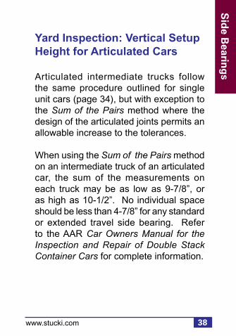
Yard Inspection: Vertical Setup Height for Articulated Cars
Articulated intermediate trucks follow the same procedure outlined for single unit cars (page 34), but with exception to the Sum of the Pairs method where the design of the articulated joints permits an allowable increase to the tolerances.
When using the Sum of the Pairs method on an intermediate truck of an articulated car, the sum of the measurements on each truck may be as low as 9-7/8”, or as high as 10-1/2”. No individual space should be less than 4-7/8” for any standard or extended travel side bearing. Refer to the AAR Car Owners Manual for the Inspection and Repair of Double Stack Container Cars for complete information.

39
Sid
e B
eari
ng
s
www.stucki.com
Yard Inspection: Vertical Setup Height for RetroXT LP, LPC, and SP Side Bearings
For yard inspection, the vertical space between the top of the RetroXT LP, LPC, or SP cage and the underside of the body side bearing (note that the RetroXT LPC measurement is taken from the notch at the top of the cage) must be 11/16" ± 1/8" (see figures 2.27 & 2.28). This measurement assumes the car is empty and is positioned on reasonably level track. If reasonably level track conditions cannot be obtained, the Sum of the Pairs method can be used by adding the measurements for the two side bearings on each truck. The sum of the measurements may be as low as 1-1/8" or as high as 1-5/8". No individual space should be less than 9/16".
If the tolerances are exceeded, and the car is empty, it must be shopped and the car body side bearing shims adjusted to obtain the specified setup height (see page 48).

Sid
e Bearin
gs
Sid
e Bearin
gs
40www.stucki.com
Fig. 2.27 — Vertical Setup Height for RetroXT LP Drop-In, LP Bolt-On, SP Drop-In, Yard Inspection
Note: Elements and cap are not shown.
Fig. 2.28 — Vertical SetupHeight for RetroXT LPC Drop-In, Yard Inspection

41
Sid
e B
eari
ng
s
www.stucki.com
Fig. 2.29 — Vertical Setup Height, Inspection Tolerances for RetroXT LP, LPC, and SP Side Bearings
Sum of the Pairs Method Add the two side bearing heights at the end of each car. The sum must be between 1-1/8" and 1-5/8". No individual space should be less than 9/16".
NEW ELASTOMERIC CENTERBOWL LINER, OR SINGLE SOLID CENTER PLATE LUBE DISC(Ref: Stucki Service Bulletin RSB9501)
METAL TO METAL CENTERBOWL CONTACT
YARD INSPECTION11/16" ± 1/8"
Note: 1) Car on reasonably level track 2) Car is empty
SHOP SET UP3/4" ± 1/16"
SHOP SET UP11/16" ± 1/16"

Sid
e Bearin
gs
Sid
e Bearin
gs
42www.stucki.com
If the car is equipped with any type of new semipermanent elastomeric centerplate liner, it must be in place when measuring for setup height adjustment. If new elastomeric bowl liners or 12" graphite lube discs are being installed, side bearing setup heights should be adjusted to 3/4" ± 1/16” for all RetroXT LP, LPC, and SP side bearings.

43
Sid
e B
eari
ng
s
www.stucki.com
Shop Inspection
General Inspection
All previous yard inspection guidelines beginning on page 31 apply in addition to the fol lowing when inspecting side bearings in a shop (with trucks removed).
After the car is shopped, chock the wheels, safely lift the car, and inspect the following components. Be certain to follow standard safe operating procedures.
Cage: Inspect cages for cracks, flaws, or unusual deformation. The cage should be securely fastened to the truck bolster. Loose fasteners should be tightened or replaced according to A. Stucki Company's installation instructions for respective side bearings. Broken or cracked cages must be replaced.

Sid
e Bearin
gs
Sid
e Bearin
gs
44www.stucki.com
Body Side Bearing: Replace plates or wedges if surface variations occur between fastener holes that are greater than 1/8" or greater than 1/16" over any 4" space. Wear plate surface must be reasonably parallel to the side bearing mounting surface of the truck bolster, with variation not exceeding 1/16" across width, or 1/8" end-to-end. Heavy rust or surface projections must be removed by grinding. Wear plate fasteners must be tight and tack welded. Heads must be flush with, or recessed from, the wear plate surface.
Roller: 4" X 3" rollers whose diameters measure less than 3-7/8" should be replaced. Minimum acceptable diameter of 3" rollers is 2-29/32". Nominal diameter of 2" rollers is actually 2-1/16", and minimum acceptable diameter for shop inspection is 2". If the edges have deformed so that the roller does not roll freely within the cage, replace the roller.

45
Sid
e B
eari
ng
s
www.stucki.com
Resilient Element: Resilient elements should be checked for cracks, gouges, or heat damage. Some elements (RB-17, RB-46, RB-56, RB-57, RB-58, RB-59, CSB column) are composed of a single material, while others consist of two materials. In general, most dual material block designs will exhibit slight separation at the horizontal interface of those two materials after several months in normal service. Blocks showing superficial horizontal separation do not need replaced. As a rule, if the interface can be manually opened to reveal 50% or more of the interface surface, the block should be replaced. Vertical cracks are acceptable unless there are more than two cracks, greater than 1/2” in length located in the lower, springing portion of the block. Cracks located below the wedge shaped metal cap do not affect its performance.

Sid
e Bearin
gs
Sid
e Bearin
gs
46www.stucki.com
Free Height Measurement: The suitability of resilient blocks for continued service can be determined by their free height measurement. Allow the blocks to relax at least one hour at room temperature after the removal of the car body. Then measure the height from the base to the highest point on the block (see table 2.1).
Table 2.1

47
Sid
e B
eari
ng
s
www.stucki.com
Load Cell Testing: A second technique used to determine the suitability of resilient blocks and their corresponding counterparts is to use a calibrated load cell. Using this technique, the load cell can be inserted between the side bearing top cap and the body side bearing wear plate. The car should be gently lowered until the top of the side bearing is 5-1/16" above the bolster. The resulting vertical force output can be compared against the nominal preload. Record this measurement and repeat the procedure for the opposite side. Worn resilient blocks and other components leading to insufficient vertical forces should be replaced. Contact A. Stucki Company for recommendations.

Sid
e Bearin
gs
Sid
e Bearin
gs
48www.stucki.com
Shop Inspection: Vertical Setup Height
If shop or yard measurements reveal side bearing setup heights are outside the acceptable range, body side bearing shim adjustments are required to correct the out-of-tolerance condition. When adjusting vertical setup height in the shop, the vertical distance between the body side bearing wear plate (or wedge) and the truck bolster surface to which the side bearing is mounted must be 5-1/16" ± 1/16", (fig. 2.30, p.50). For the RetroXT LP and SP side bearings, the vertical space between the top of the cage and the underside, or wearing surface, of the body side bearing must be 11/16" ± 1/16" (fig. 2.31, p. 50). For the RetroXT LPC side bearing, The vertical space between the top of the cage notch and the underside, or wearing surface, of the body side bearing must be 11/16" ± 1/16" (fig. 2.32, p. 51).

49
Sid
e B
eari
ng
s
www.stucki.com
These measurements assume the car is empty, positioned on reasonably level track, and has positive centerplate contact. Tops of metal rockers or rollers should not be used as reference points to measure setup height for constant contact side bearings.

Sid
e Bearin
gs
Sid
e Bearin
gs
50www.stucki.com
(Assumes meta l to metal contact in centerbowl)
Fig. 2.31 — Vertical Setup Height for RetroXT LP Drop-In, Bolt-On, SP Drop-In, Shop Inspection
Fig. 2.30 — Vertical Setup Height, Shop Inspection
(Assumes metal to metal contact in centerbowl)
5-1/16" ± 1/16"

51
Sid
e B
eari
ng
s
www.stucki.com
Fig. 2.32 — Vertical Setup Height for RetroXT LPC, Shop Inspection

Sid
e Bearin
gs
Sid
e Bearin
gs
52www.stucki.com
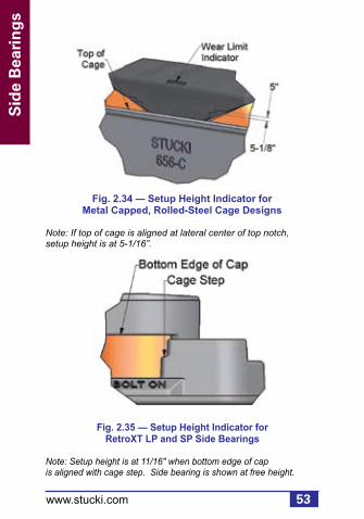
Figures 2.33, 2.34, 2.35, and 2.36 show quick reference indicators which can be used for an at-a-glance check for setup height.
Fig. 2.33 — Setup Height Indicator for Compact Column Side Bearing
Note: Setup is at 5-1/16" when bottom of cap cutout is aligned with top of cage. Side bearing is shown at free height.
53
Sid
e B
eari
ng
s
www.stucki.com
Fig. 2.34 — Setup Height Indicator for Metal Capped, Rolled-Steel Cage Designs
Note: If top of cage is aligned at lateral center of top notch, setup height is at 5-1/16”.
Fig. 2.35 — Setup Height Indicator for RetroXT LP and SP Side Bearings
Note: Setup height is at 11/16" when bottom edge of cap is aligned with cage step. Side bearing is shown at free height.

Sid
e Bearin
gs
Sid
e Bearin
gs
54www.stucki.com
Fig. 2.36 — Setup Height Indicator for RetroXT LPC Side Bearings
Note: Setup is at 11/16" when cap step is aligned with top of cage. Side bearing is shown at free height.

55
Sid
e B
eari
ng
s
www.stucki.com
To increase the setup height, shims must be removed. Likewise, to reduce the setup height, shims must be added to the car body side bearing.
Do not place shims under side bearing cages to adjust setup heights, except if the car has welded-in-place body side bearings on a cast body bolster, when shimming beneath cages is the only option.
Never relubricate a side bearing in service, unless 1) replacing nonmetal capped blocks or 2) metal caps and body side bearings are being replaced simultaneously. In the case of nonmetal capped resilient blocks, apply a thin film of lithium based grease to the body side bearing. In the case of metal capped resilient blocks, apply a 1-1/2” diameter dab of lithium based grease to the center of the new metal cap.

56
Friction
Elem
ents
www.stucki.com
3. Resilient Friction Elements (RFE)
General Requirements
To check friction wedge rise, a mustache gage per Rule 88, AAR Field Manual, can be used.
The following illustrations identify specific friction elements and components. It is important that all components shown for a specific wedge are present and in good condition. Pads manufactured by A. Stucki Company are identified by their orange color. The friction casting identification is on the bottom, which is not visible when the truck is fully assembled. Table 3.1 on the following page cross-references product.

57
Fri
ctio
n E
lem
ents
www.stucki.com
*Requires use of Stucki RFE-16 D-5 wedge springs (or Barber B432/B433 combination) with 3/8” Stucki shim plate.** Discontinued
Table 3.1

58
Friction
Elem
ents
www.stucki.com
Fig. 3.1 — RFE-16, for Barber® Trucks
Fig. 3.2 — RFE-41, for Barber® S-2-HD Trucks

59
Fri
ctio
n E
lem
ents
www.stucki.com
Fig. 3.4 — RFE-18, for Ride Control Trucks
Fig. 3.3 — RFE-51, for Barber® S-2-D Trucks

60
Friction
Elem
ents
www.stucki.com
Fig. 3.6 — RFE-53, for Super Service Ride Master Trucks
Fig. 3.5 — RFE-26, for Super Service Ride Control Trucks
61
Fri
ctio
n E
lem
ents
www.stucki.com
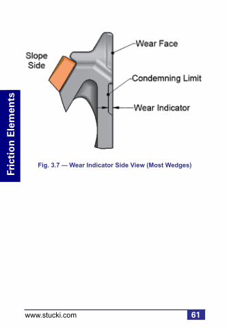
Fig. 3.7 — Wear Indicator Side View (Most Wedges)

62
Friction
Elem
ents
www.stucki.com
Yard Inspection
Inspect wear indicators on the vertical face of the wedge. Replace wedges when the wear indicators are no longer visible. New wedges will have approximately 3/8” of wear indicator visible. A mustache gage can be used to check wedge rise. Wedge rise limits for RFEs are the same as for the all-metal friction shoes they replace (see AAR Field Manual, Rule 88). For the RFE-18 and RFE-26, wedge rise is excessive when the hole on the front of the casting is entirely above the top plate of the bolster. The RFE-16 wedge rise limit indicator is the bottom of the face wear indicator itself.

63
Fri
ctio
n E
lem
ents
www.stucki.com
The upper corners of the RFE-18 and RFE-26 resilient pads may experience splitting. These corner splits normally propagate across the top of the pad, in line with the upper edge of the bolster, and do not affect the performance of the wedge. Cars having pads exhibiting such cracks should not be shopped for pad or wedge replacement.
Check top edge of resilient urethane pads for flush seating against the wedge and bolster pocket. Any pad cracks above the area of contact with the bolster pocket are acceptable and not cause for renewal. The appearance of “stringy” extrusions of pad material between the pad and casting at the top edge could be indicative of severe hunting, and A. Stucki Company should be consulted.

64
Friction
Elem
ents
www.stucki.com
Shop Inspection
In addition to the previous yard inspection procedures, inspection in the repair shop should include the following procedures:
Column Wear Plate: Check closely for cracks, loose or missing fasteners, or excessive wear, and replace as necessary. Plates worn more than 1/8” at any area must be replaced. Column wear plates must be reasonably parallel, and spacing between plates must be in accordance with AAR requirements.
RFE Casting and Resilient Pad: Chipping of casting corners is acceptable. Wedges having sizable pieces missing, or having obvious cracks, must be replaced.

65
Fri
ctio
n E
lem
ents
www.stucki.com
If wedge rise measurements indicate wedges are above condemnable heights, both complete wedges should be replaced. The exception is if resilient pad(s) are severely damaged, and casting has at least 3/16” face wear indicator remaining, then it is acceptable to replace the pads only.
Pry old pads from the casting with a screwdriver, and install new pads by aligning the post on the back of the pad with the hole in the sloped face of the casting. Strike the pad face with a mallet to seat it onto the casting.
Patches of dark, flaky material on the faces of the pads are common, and produce no detrimental effects. This is not cause for renewal.
In the case of the RFE-18, RFE-26, and RFE-53, if cracks emanating from the upper or lower corners of the pads have extended downward toward the center of the pad more than 3/4”, then the cracked pad should be replaced.

66
Friction
Elem
ents
www.stucki.com
Wedge Spring: Broken wedge springs must be replaced. The springs supplied by Stucki for the various RFE models are virtually identical to the springs supplied by the manufacturers of the all-metal wedge systems. Free heights of springs should be checked. Refer to A. Stucki Company’s RFE Installation Instructions for minimum allowable free heights.
Stucki RFEs and all-metal friction wedges should never be combined in the same truck. RFEs must always be replaced in kind.
67
Hyd
rau
lic S
tab
ilize
rs
www.stucki.com
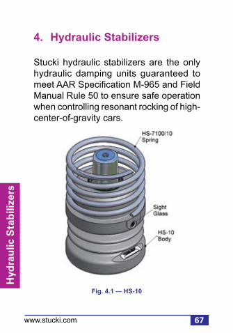
4. Hydraulic Stabilizers
Stucki hydraulic stabilizers are the only hydraulic damping units guaranteed to meet AAR Specification M-965 and Field Manual Rule 50 to ensure safe operation when controlling resonant rocking of high-center-of-gravity cars.
Fig. 4.1 — HS-10

Sid
e Bearin
gs
68
Hyd
raulic S
tabilizers
www.stucki.com
Fig. 4.2 — HydraShox Platinum (HS-7 replacement)
Fig. 4.3 — HS-7100
Note: Available as reconditioned unit only.

69
Hyd
rau
lic S
tab
ilize
rs
www.stucki.com
Yard and Shop Inspection
Hydraulic stabilizers should be positioned vertically upright with the body spring properly seated between the stabilizer body and the bolster. Units not properly positioned or seated on the side frame must be repositioned correctly. If stabilizer body has been damaged due to bolster or side frame lug interference to allow oil leakage at damaged area, unit must be replaced, and the damaged stabilizer should be scrapped.
Stucki hydraulic stabilizers have a sight glass on one side of the reservoir to check for proper operating fluid level. On the HS-7 and Hydrashox Platinum, this window is protected from dirt by a plastic cap, which must be removed to make the visual check. If the cap is missing, clean out any dirt on the surface of the glass. (A sliver of tie wood works well for this task.) Be sure the unit is sitting in its normal upright position when inspecting the sight glass.

Sid
e Bearin
gs
70
Hyd
raulic S
tabilizers
www.stucki.com
f
A. Window Full
Unit OK
C. Empty
Replace ASAP
B. Partially Full
Replace at the next maintenance interval
A flashlight may be helpful in making the sight glass inspection. Figure 4.4 illustrates one of three conditions that may be encountered during inspection.
Fig. 4.4 — Hydraulic Stabilizer Sight Glass Window

71
Hyd
rau
lic S
tab
ilize
rs
www.stucki.com
Condition A. The oil level in the reservoir is full. The entire glass area will appear dark, and the unit should be left in service, regardless of any external sludge accumulation.
Condition B. The oil level has dropped to the sight glass window, and only the upper portion of two shiny rings appears to be reflecting light. This indicates sufficient fluid remaining in the reservoir for adequate operation; however, it is the first warning the unit should be scheduled for replacement when the car is next shopped for routine maintenance. This is not an AAR or FRA defect as far as foreign cars are concerned. For systems cars, however, it is advisable to replace when this condition is found.

Sid
e Bearin
gs
72
Hyd
raulic S
tabilizers
www.stucki.com
Condition C. The oil level has dropped below the sight glass area, and the two shiny rings are completely visible. The unit should be replaced as soon as possible. This condition constitutes a viable AAR or FRA defect.
Stucki hydraulic stabilizers incorporate a low pressure seal on the piston rod, which will gradually, but continually pass slight amounts of oil under normal operating conditions. This fluid loss is compensated for by the reserve oil. The appearance of external oil/sludge accumulation is not an indication of a defective unit.
73
Hyd
rau
lic S
tab
ilize
rs
www.stucki.com
HS-7 and HS-7100 units removed on account of low oil level should be returned to:
A. Stucki Company2155 Allen Street Extension
Falconer, NY 14733
Please call 716.665.5217 in advance for a required delivery appointment.
The piston rods should be protected from damage in transit by use of the protective sleeve provided on the rod of the new replacement unit.
HS-10s are not able to be rebuilt and should be replaced in kind. HS-6s have been discontinued and should be replaced by HydraShox Platinum Series. Once reserve oil has been depleted, HS-6s should be discarded.

74
Sid
e Bearin
gs
Intern
ation
al Pro
du
cts
www.stucki.com
5. International Products
A. Stucki Company manufactures several products domestically and off-shore that are designed for specific applications to freight wagons in various countries outside North America. These products, in general, follow the same installation and inspection requirements as those for our conventional domestic products of the same type (section 2.0). For that reason those instructions will not be repeated here, but exceptions to conventional installation or inspection procedures will be noted.
Inte
rnat
ion
al P
rod
uct
s
75www.stucki.com
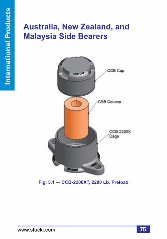
Australia, New Zealand, and Malaysia Side Bearers
Fig. 5.1 — CCB-2200XT, 2200 Lb. Preload

76
Sid
e Bearin
gs
Intern
ation
al Pro
du
cts
www.stucki.com
Fig. 5.2 — CCB-3000XT, 3000 Lb. Preload

Inte
rnat
ion
al P
rod
uct
s
77www.stucki.com
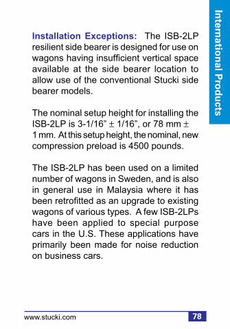
Fig. 5.3 — ISB-2LP, 4500 Lb. Preload
Note: Low profile. See installation exceptions on page 78.
78
Sid
e Bearin
gs
Intern
ation
al Pro
du
cts
www.stucki.com
Installation Exceptions: The ISB-2LP resilient side bearer is designed for use on wagons having insufficient vertical space available at the side bearer location to allow use of the conventional Stucki side bearer models.
The nominal setup height for installing the ISB-2LP is 3-1/16” ± 1/16”, or 78 mm ± 1 mm. At this setup height, the nominal, new compression preload is 4500 pounds.
The ISB-2LP has been used on a limited number of wagons in Sweden, and is also in general use in Malaysia where it has been retrofitted as an upgrade to existing wagons of various types. A few ISB-2LPs have been applied to special purpose cars in the U.S. These applications have primarily been made for noise reduction on business cars.
Inte
rnat
ion
al P
rod
uct
s
79www.stucki.com
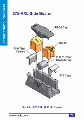
675-RXL Side Bearer
Fig. 5.4 — 675-RXL, 2200 Lb. Preload

80
Sid
e Bearin
gs
Intern
ation
al Pro
du
cts
www.stucki.com
The 675-RXL is a low preload version of the standard Stucki resilient, metal-capped 675-RL. The 675-RXL has a preload at 5-1/16” setup height of 2200 pounds (compared to 3000 pounds for the RL). The only physical difference between the two models is the resilient block design.

Inte
rnat
ion
al P
rod
uct
s
81www.stucki.com
656-CRL Side Bearer
Fig. 5.5 — 656-CRL, 3500 Lb. Preload
82
Sid
e Bearin
gs
Intern
ation
al Pro
du
cts
www.stucki.com
The 656-CRL is a low preload version of the standard 656-CR. The 656-CRL has a preload at 5-1/16” setup height of 3500 pounds (preload of the standard 656-CR is 6000 pounds). The only physical difference between the models is the resilient block. 656-CRLs are in use in Australia and New Zealand, and on a number of freight wagons in Malaysia. They are also used in North America on one group of 5-unit 100 ton articulated double stack cars.

Inte
rnat
ion
al P
rod
uct
s
83www.stucki.com
The JOEY Series Side Bearers
For wagons with only mating plates of steel for body and bogie side bearers, a cast pocket was designed that could be retrofit welded into the bogie bolster to contain the Stucki components (to accommodate 5-1/6” setup height). New bogie bolsters can also be cast with this pocket integral. The inside dimensions of the JOEY pocket replicate the inside length and width of the Stucki 656-C single roller side bearing cage with the end closures installed. The proper base contour for seating the resilient blocks and roller is achieved by use of a separate base plate, a casting designed to replicate the inside floor of the Stucki 656-C cage. Thus, the internal components of any standard Stucki model that uses one of our shorter (C length) cages can fit into the JOEY pocket, and the end closures are not required.
84
Sid
e Bearin
gs
Intern
ation
al Pro
du
cts
www.stucki.com
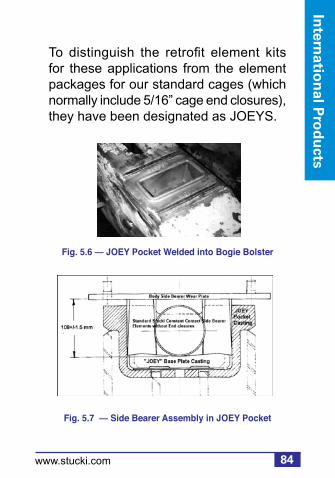
Fig. 5.6 — JOEY Pocket Welded into Bogie Bolster
Fig. 5.7 — Side Bearer Assembly in JOEY Pocket
To distinguish the retrofit element kits for these applications from the element packages for our standard cages (which normally include 5/16” cage end closures), they have been designated as JOEYS.

Inte
rnat
ion
al P
rod
uct
s
85www.stucki.com
Several slightly different versions of the base plate casting have been manufactured, varying in thickness. Regardless of which base plate and pocket casting is used, the normal setup is established by placing a 108 mm high gage block set into the center of the base plate, then lowering the wagon body to the bogie and measuring the clearance to the body side bearer wear plate. From this measurement, determine the amount of shim required to bring the space within 1.5 mm of the top of the gage block. Generally it is advisable when making JOEY pocket applications of the Stucki metal capped side bearings, 675-RL, 675-RXL, or 685-RM, to specify the JOEY element kits to have the RB-27 metal cap. The flat sides of the RB-27 cap provide greater area of engagement with the sides of the JOEY pockets, which results in less wear than if the RB-24 or RB-34 caps are used.

86
Sid
e Bearin
gs
Intern
ation
al Pro
du
cts
www.stucki.com
European Side BearersSee Low Profile ISB-2LP on page 77.
South American Side Bearings
SA-2500-2R Side Bearing Insert
Fig. 5.8 — SA-2500-2R
The SA-2500-2R is a double roller side bearing designed for drop-in insertion into low profile friction block housings which are integrally cast or bolted onto truck bolsters.

Inte
rnat
ion
al P
rod
uct
s
87www.stucki.com
SA-5000-2R Side Bearing Insert
The SA-5000-2R is a double roller side bearing designed for drop-in insertion into friction block housings which are integrally cast or bolted onto truck bolsters.
Roller clearance for both the SA-2500-2R and SA-5000-2R models should be set at 1/4” ± 1/16” (6 mm ± 1 mm) for wagons having 1,435 mm gauge trucks, or at 3/16” ± 1/16”) (5 mm ± 1 mm) for wagons having 1,000 mm (or meter) gauge trucks.
Fig. 5.9 — SA-5000-2R

88
Sid
e Bearin
gs
Intern
ation
al Pro
du
cts
www.stucki.com
CDR Side Bearing
The CDR is a double roller side bearing designed for bolt-on applications in the same manner as the conventional Stucki 688-B double roller side bearing.
Fig. 5.10 — CDR Double Roller Side Bearing
Inte
rnat
ion
al P
rod
uct
s
89www.stucki.com
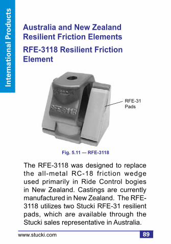
The RFE-3118 was designed to replace the all-metal RC-18 friction wedge used primarily in Ride Control bogies in New Zealand. Castings are currently manufactured in New Zealand. The RFE-3118 utilizes two Stucki RFE-31 resilient pads, which are available through the Stucki sales representative in Australia.
Australia and New Zealand Resilient Friction Elements
RFE-3118 Resilient FrictionElement
Fig. 5.11 — RFE-3118
RFE-31Pads

90
Sid
e Bearin
gs
Intern
ation
al Pro
du
cts
www.stucki.com
The RFE-3234 was designed to replace the all-metal RC-134 friction wedge used primarily in Ride Control bogies in Australia. Castings are currently manufactured in Australia. The RFE-3234 utilizes two Stucki RFE-32 resilient pads, which are available through the Stucki sales representative in Australia.
RFE-3234 Resilient Friction Element
Fig. 5.12 — RFE-3234
RFE-32Pads

Inte
rnat
ion
al P
rod
uct
s
91www.stucki.com
The RFE-3262 was designed to replace the all-metal RC-262 friction wedge used primarily in Ride Control bogies in Australia. Castings are currently manufactured in Australia. The RFE-3262 utilizes two Stucki RFE-32 resilient pads, which are available through the Stucki sales representative in Australia and New Zealand.
RFE-3262 Resilient Friction Element
Fig. 5.13 — RFE-3262
RFE-32Pads
92
Sid
e Bearin
gs
Intern
ation
al Pro
du
cts
www.stucki.com
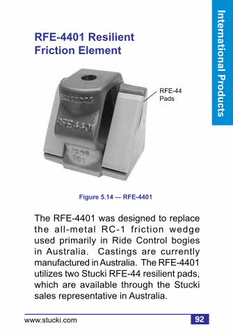
RFE-4401 Resilient Friction Element
The RFE-4401 was designed to replace the all-metal RC-1 fr ict ion wedge used primarily in Ride Control bogies in Australia. Castings are currently manufactured in Australia. The RFE-4401 utilizes two Stucki RFE-44 resilient pads, which are available through the Stucki sales representative in Australia.
Figure 5.14 — RFE-4401
RFE-44Pads

93
Bra
ke B
eam
s
www.stucki.com
6. Brake Beams
Fig. 6.1 — Reversible Brake Beam

Sid
e Bearin
gs
Brake B
eams
94www.stucki.com
Product Description
Stucki manufactures rugged, fatigue and vibration resistant brake beams to support both composition and cast iron shoes. All brake beams are provided with angle corrected (AC) heads, fixed or replaceable, to optimize brake shoe wear and provide for optimum life. Its durable and lightweight construction provides easy brake shoe inspection and replacement. Hardened pinholes for extended life and safety allow for superior service life. This product can be supplied with a fixed strut (not shown), a fixed head, an easy to use reversible strut, or a replaceable head (RC). Replaceable heads provide significant cost savings as compared to replacing whole beams for damaged heads. Both #18 and #24 sizes are available.

95
Bra
ke B
eam
s
www.stucki.com
Inspection
Replacement of brake beams can be considered for any of the inspection criteria below. Refer to AAR Field Manual of Interchange, Rule 6 for a detailed list of wear limits, gauging, and causes for renewal.
1. Any brake beam parts which are cracked, broken, or missing
2. Damage or wear on brake beam head (heads alone can be replaced in lieu of entire beams – RC beams)
3. Twisted beams (greater than 1 inch when comparing opposite heads against wheels)
4. Worn end extensions
5. Bent or twisted struts
6. Strut pin holes worn 3/16” or more
7. Slot lever worn 1/8” or more

Sid
e Bearin
gs
Brake B
eams
96www.stucki.com
Reversible Brake Beam
Three steps for converting either RH or LH in the field.
First • Use screwdriver to pull retainer & pin (If tight, pin may be pushed from the opposite end, by the screwdriver).
Second• Insert steel bar in strut lever slot.• Tilt rotating strut 90 degrees, until the slots in end casting match slots in strut.
Third• Re-insert pin with groove end last.• Reapply retainer by hand at pin groove (push it safely in place with screwdriver).

97
Bra
ke B
eam
s
www.stucki.com
Fig. 6.2 — Strut and Pin
Pin
Retainer
StrutLeverSlot

Sid
e Bearin
gs
Brake B
eams
98www.stucki.com
Replaceable Head Procedure
1. Remove damaged head from brake beam assembly from the side of
the car.2. Position replaceable head to align holes.3. Insert bolt through replaceable head
and beam assembly combined. Apply washer assembly (large washer first, small washer next), and lock nut to threaded bolt. Tighten lock nut until orange capsule breaks (or 300 ft-lbs equivalent).
4. Install brake shoe and return to service.
Fig. 6.3 — Replaceable Brake Beam Head
99
Rec
on
dit
ion
ing
Ser
vice
s
www.stucki.com
Draft Gear
Independent Draft Gear, a division of A. Stucki Company, reconditions, tests, and pins the most commonly available draft gear per AAR M-901B Specifications. Refer to AAR Interchange Rule 21, Section B, Groups J & M for an overview of the draft gear models that we recondition.
Other g roup type gears can be reconditioned and used for captive service.
7. Reconditioning Services
100
Reco
nd
ition
ing
Services
www.stucki.com
Inspection
Reconditioning of a draft gear can be considered when any of the defects listed in Secton A of the AAR Field Manual Rule 21 are present. Refer to the manual for a detailed list of wear limits, gauging, and cause for renewal.
Also, refer to manufacturer’s specifications for In-Car and Out-of-Car inspection requirements for each individual model.

101
Rec
on
dit
ion
ing
Ser
vice
s
www.stucki.com
Fig. 7.1 — Draft Gear

102
Reco
nd
ition
ing
Services
www.stucki.com
Date Classification
The original manufacture date or last reconditioning date should be located on the draft gear case. Per AAR Field Manual Rule 21, draft gear must be:
• Reconditioned after 16 years from the date of original manufacture, or 10 years from the last recondition date. Should a date not be readily apparent on the case, the gear must be reconditioned.
• Tested and pinned if the gear is less than 16 years old or has been reconditioned within the last 10 years.
• Pinned only if the gear was manufactured or tested within the last 10 years.

103
Rec
on
dit
ion
ing
Ser
vice
s
www.stucki.com
Friction Component Classification:
Irrespective of the gear’s date classification, a gear must be reconditioned if any of its friction components are broken, damaged in any way, or missing.
Gears are c lass i f ied as FC/C/D ( F r i c t i o n C o m p o n e n t C a s e Damage) per the following criteria:
1. More than 1 broken or missing friction component 2. Center wedge is damaged 3. The gear is stuck in a compressed position

104
Reco
nd
ition
ing
Services
www.stucki.com
Case Classification: As in the case of friction component damage, a draft gear must be rebuilt if the case has been subject to excessive wear or is damaged. Gears with cases that meet the following are also considered FC/C/D:
1. Wall thickness – visibly worn case wall 2. Torch cut – 1 inch or more
Scrap Classification: Gears with bulges, split cases or cracks in excess of 2 inches cannot be repaired and are classified as scrap. Also, gears not listed on the IDG list of acceptable gears (detailed list can be found at www.draft-gear.com) are either not reconditionable or are obsolete and therefore classified as scrap.
105
Rec
on
dit
ion
ing
Ser
vice
s
www.stucki.com
Gears which meet the cri teria for reconditioning should be shipped to:
Independent Draft Gear1000 Martin Luther King Jr. Blvd.
Farrell, PA 16121Phone: 724.981.2251
Fax: 724.981.2256

106
Reco
nd
ition
ing
Services
www.stucki.com
Repair Services
American Industries, Inc. provides railcar repair and reconditioning services to the railroad industry. We also provide new, secondhand, gauged, and reconditioned railroad parts. Facilities in Sharon, PA are certified under AAR M-212 and M-214, as well as QA certification M-1003.
Reconditioning services include:• Wheel Sets• Air Brakes• Bolsters• Sideframes• Couplers• Yokes• Draft Gears• Complete Truck Assemblies
Secondhand parts include:• Air Brake Parts• Couplers• Yokes

107
Rec
on
dit
ion
ing
Ser
vice
s
www.stucki.com
New parts include:• Air Brake Parts (manufactured by New York Air Brake)
American Industries is certified to reprofile freight car and locomotive wheel sets to any profile. American Industries is also AAR certif ied for mounting new or reconditioned roller bearings.
Also provides interchange usable or second hand repairable axles and roller bearings at competitive prices.

Sid
e Bearin
gs
Pro
du
ct Ind
ex
108www.stucki.com
Product Index
656-C ................................................. 28656-CR .............................................. 17656-CRH............................................ 20656-CRL ............................................ 81656-SLB............................................. 27675-RL ............................................... 21675-RXL ............................................ 79685-RM .............................................. 22688-B ................................................. 29688-BR .............................................. 18690-RL ............................................... 19BUS-18-BRAC-CHL .......................... 93BUS-18-BRAC-CHR ......................... 93BUS-18-LRRC-CHL ........................... 93BUS-18-LRRC-CHR .......................... 93 BUS-24-BRAC-CHL .......................... 93BUS-24-BRAC-CHR .......................... 93 BUS-24-LRRC-CHL ........................... 93BUS-24-LRRC-CHR .......................... 93 CCB-2200XT ..................................... 75CCB-3000XT ..................................... 76CCB-4500XT ....................................... 9CCB-6000XT ....................................... 9

109
Pro
du
ct In
dex
www.stucki.com
Product Index (continued)
CDR ................................................... 88CSB® .................................................... 8 HS-7 .................................................. 68HS-10 ................................................ 67HS-7100 ............................................ 68HydraShox Platinum Series............... 68ISB-2LP ............................................. 77ISB-9DR ............................................ 23ISB-9DRL .......................................... 24ISB-10................................................ 25ISB-12................................................ 26JOEY ................................................. 83RetroXT 4500 .................................... 16RetroXT 5400B .................................. 14RetroXT 5400C .................................. 15RetroXT LP Bolt-On ........................... 10RetroXT LP Drop-In ............................11RetroXT LPC ..................................... 12RetroXT SP ....................................... 13RFE-16 .............................................. 58RFE-18 .............................................. 59
Sid
e Bearin
gs
Pro
du
ct Ind
ex
110www.stucki.com
Product Index (continued)
RFE-26 .............................................. 60RFE-41 .............................................. 58RFE-51 .............................................. 59RFE-53 .............................................. 60RFE-3118 .......................................... 89RFE-3234 .......................................... 90RFE-3262 .......................................... 91RFE-4401 .......................................... 92SA-2500-2R ....................................... 86SA-5000-2R ....................................... 87SSB® .................................................... 7
Ride Control, Super Service Ride Control, Low Level Ride Control, and Super Service Ridemaster are federally registered trade marks of ASF-Keystone, Inc. Barber is a federally registered trade mark of Barber, Inc. Miner is a federally registered trade mark of Miner Enterprise, Inc. Cardwell-Westinghouse is a federally registered trade mark of Wabtec Corporation.


113
Rec
on
dit
ion
ing
Ser
vice
s
www.stucki.com
2600 Neville Road, Pittsburgh, PA 15225 412.771.7300, Fax: 412.771.7308
In Australia: GEMCO 61 8 9454 9666
In Brazil: A. Stucki do Brasil Ltda +55 (11) 3842 4630
www.stucki.com email: [email protected]
Improving Ride Quality Since 1911

2www.stucki.com
1. Scope ..............................................................5
2. Truck and Body Side Bearings .....................6 General Requirements ..................................6 Extended Travel CCSB ...............................7 Extended Travel RetroXT CCSB ...............10 Extended Travel Upgrade CCSB...............14 Standard Travel CCSB ..............................17 Roller Side Bearings..................................28 Plate and Wedge .......................................30 Yard Inspection ............................................31 General Inspection ....................................31 Setup Height..............................................34 Single Unit Cars ......................................34 Articulated Cars ......................................38 RetroXT LP, LPC, and SP .......................39 Shop Inspection...........................................43 General Inspection ....................................43 Setup Height..............................................48 Visual Height Inspection .........................52
3. Resilient Friction Elements .........................56 Product Reference Table .............................57 Products Barber Trucks ............................................58 ASF Trucks ................................................59 Wear Indicator .............................................61 Yard Inspection ............................................62 Shop Inspection...........................................64
Table of Contents

3www.stucki.com
4. Hydraulic Stabilizers .................................. 67 Products .................................................... 67 Yard and Shop Inspection ......................... 69
5. International Products ............................... 74 Side Bearings ............................................ 75 Australia, New Zealand and Malaysia ..... 75 Europe ..................................................... 86 South America ......................................... 86 Resilient Friction Elements ........................ 89 Australia and New Zealand ..................... 89
6. Brake Beams .............................................. 93 Products .................................................... 94 Inspection .................................................. 95 Reversing the Brake Beam ....................... 96 Replacing the Head ................................... 98
7. Reconditioning Services ........................... 99 Draft Gear.................................................. 99 Truck Components .................................. 106 Other Components .................................. 106
Product Index ........................................... 108
Tabel of ContentsTable of Contents

4www.stucki.com
A. Stucki Company, a division of Hansen, Inc., is a worldwide leader in freight car dynamic control products. Reconditioning and repair services are provided through two sister companies; Independent Draft Gear and American Industries.

5www.stucki.com
1. Scope
This pocket guide provides recommended procedures for yard and repair shop inspection of products manufactured and reconditioned by A. Stucki Company, including truck side bearings, body side bearings, resilient friction elements, hydraulic stabilizers, brake beams, and draft gears.
This guide is intended primarily for product inspection and maintenance guidance, and does not cover initial product installation procedures. Drawings and installation instructions for each of Stucki’s products may be obtained from the A. Stucki Company online catalog, located on the Stucki Web Site (www.stucki.com), or by calling 412.771.7300.

Sid
e Bearin
gs
Sid
e Bearin
gs
6www.stucki.com
2. Truck and Body Side Bearings
General Requirements
The tools required for inspection include a set of calipers, a measuring tape, and a flashlight.

7
Sid
e B
eari
ng
s
www.stucki.com
Fig. 2.1 — Shear Side Bearing (SSB)
Note: Replacement cages are ordered by specifying preload, i.e. 6000XT Cage, where 6000 = preload, XT for extended travel.

Sid
e Bearin
gs
Sid
e Bearin
gs
8www.stucki.com
Note: Replacement cages are ordered by specifying preload, i.e. 6000XT Cage, where 6000 = preload, XT for extended travel.
Fig. 2.2 — Column Side Bearing (CSB)

9
Sid
e B
eari
ng
s
www.stucki.com
Fig. 2.3 — Compact Column Side Bearing
Note: Replacement cages are ordered by specifying preload, i.e. CCB 6000XT Cage, where 6000 = preload, XT for extended travel.

Sid
e Bearin
gs
Sid
e Bearin
gs
10www.stucki.com
Fig. 2.4 — RetroXT LP Bolt-On, 4500 Lb. Preload

11
Sid
e B
eari
ng
s
www.stucki.com
Fig. 2.5 — RetroXT LP Drop-In, 4500 Lb. Preload
For monocast or welded bolster pocket, approximately 4-1/4" x 9-1/4", low profile design.

Sid
e Bearin
gs
Sid
e Bearin
gs
12www.stucki.com
Fig. 2.6 — RetroXT LPC Drop-In, 4500 Lb. Preload
For monocast or welded bolster pocket, approximately 3-1/2" x 8-1/4", low profile design.

13
Sid
e B
eari
ng
s
www.stucki.com
Fig. 2.7 — RetroXT SP Drop-In, 4500 Lb. Preload
For monocast or welded bolster pocket, approximately 4-1/4" x 9-1/4", standard profile design.

Sid
e Bearin
gs
Sid
e Bearin
gs
14www.stucki.com
Fig. 2.8 — RetroXT 5400B (previously CCU-5400XT), 5400 Lb. Preload
Note: This is an extended travel upgrade for the 688-BR, the ISB-9DR, the ISB-12, and the 688-B.

15
Sid
e B
eari
ng
s
www.stucki.com
Fig. 2.9 — RetroXT 5400C, 5400 Lb. Preload
Note: This an extended travel upgrade for the 656-CR, the 656-CRH, and the 656-C.
Sid
e Bearin
gs
Sid
e Bearin
gs
16www.stucki.com
Fig. 2.10 — RetroXT 4500, 4500 Lb. Preload
Note: This an extended travel upgrade for the 690-RL.
17
Sid
e B
eari
ng
s
www.stucki.com
Fig. 2.11 — 656-CR, 6000 Lb. Preload
Note: The 656-C cage can accept the RetroXT 5400C upgrade kit to convert product to extended travel.

Sid
e Bearin
gs
Sid
e Bearin
gs
18www.stucki.com
Fig. 2.12 — 688-BR, 6000 Lb. Preload
Note: The 688-B cage can accept the RetroXT 5400B upgrade kit to convert product to extended travel.
19
Sid
e B
eari
ng
s
www.stucki.com
Fig. 2.13 — 690-RL, 3600 Lb. Preload
Note: The 690 cage can accept the RetroXT 4500 upgrade kit to convert product to extended travel.

Sid
e Bearin
gs
Sid
e Bearin
gs
20www.stucki.com
Fig. 2.14 — 656-CRH, 5400 Lb. Preload
Note: The 656-C cage can accept the RetroXT 5400C upgrade kit to convert product to extended travel.
21
Sid
e B
eari
ng
s
www.stucki.com
Fig. 2.15 — 675-RL, 3000 Lb. Preload

Sid
e Bearin
gs
Sid
e Bearin
gs
22www.stucki.com
Fig. 2.16 — 685-RM, 4500 Lb. Preload
23
Sid
e B
eari
ng
s
www.stucki.com
Fig. 2.17 — ISB-9DR, 4500 Lb. Preload
Note: The 688-B cage can accept the RetroXT 5400B upgrade kit to convert product to extended travel.

Sid
e Bearin
gs
Sid
e Bearin
gs
24www.stucki.com
Fig. 2.18 — ISB-9DRL, 4500 Lb. Preload

25
Sid
e B
eari
ng
s
www.stucki.com
Fig. 2.19 — ISB-10, 4500 Lb. Preload

Sid
e Bearin
gs
Sid
e Bearin
gs
26www.stucki.com
Fig. 2.20 — ISB-12, 5400 Lb. Preload
Note: The 688-B cage can accept the RetroXT 5400B upgrade kit to convert product to extended travel.

27
Sid
e B
eari
ng
s
www.stucki.com
Fig. 2.21 — 656-SLB, No Preload

Sid
e Bearin
gs
Sid
e Bearin
gs
28www.stucki.com
Fig. 2.22 — 656-C
Note: The 656-C cage can accept the RetroXT 5400C upgrade kit to convert product to extended travel.

29
Sid
e B
eari
ng
s
www.stucki.com
Fig. 2.23 — 688-B
Note: The 688-B cage can accept the RetroXT 5400B upgrade kit to convert product to extended travel.
Sid
e Bearin
gs
Sid
e Bearin
gs
30www.stucki.com
Fig. 2.24 — Body Side Bearings (Plate and Wedge)

31
Sid
e B
eari
ng
s
www.stucki.com
Yard Inspection
General Inspection
Physically identify the side bearing model from the illustrations in Section 2. Be sure all components for that model are present and in the correct orientation. Missing or damaged components should be replaced prior to placing the car back into service.
Cage: Inspect cages for cracks, flaws, or unusual deformation. The cage must be securely fastened to the truck bolster.
Body Side Bearing: Plates or wedges must be securely tightened and the surface must be smooth. Fastener heads must not protrude below the wear plate surface.

Sid
e Bearin
gs
Sid
e Bearin
gs
32www.stucki.com
End Closure: End closures must be in place and not broken. ISB models have only one end closure.
Resilient Element: Resilient elements should be checked for evidence of overheating. Resilient urethane can be permanently damaged at high temperatures brought about by severe truck hunting or exposure to extreme temperatures generated by improperly used thaw sheds.
If any signs of heat damage exist (such as severe cracking, bulging, or deformation), replace the urethane blocks. Note that the 688-BR and 690-RL cars need not be shopped for repairs for a single block having a missing top portion. The side bearing will function adequately with only 2 of the 3 blocks contacting. Replace the defective block when the car is next shopped for required maintenance or other repairs. Bad-order the car if two or more block tops are missing.

33
Sid
e B
eari
ng
s
www.stucki.com
Rocker: Rockers may not always be seated on the bottom of the cage, and clearance should not be used as a setup height criterion. While in service, vertical movement may occur. This has no effect on the performance of the side bearing. Rockers contact the body side bearing as the car rocks or leans. Light wear of the upper and lower surfaces of the
rockers is normal.
Sid
e Bearin
gs
Sid
e Bearin
gs
34www.stucki.com
Yard Inspection: Vertical Setup Height
Figure 2.25 summarizes the measurement ranges allowable for yard inspection. For articulated cars, see page 38. For RetroXT LP, LPC, and SP Side Bearings, see pages 39-42.
For yard inspection, the vertical distance between the body side bearing wear plate (or wedge) and the truck bolster surface to which the side bearing cage is mounted must be between 4-15/16" and 5-3/16", as illustrated in figure 2.25. This measurement assumes the car is empty and is positioned on reasonably level track. Be alert to the possibility of encountering shims under side bearing cages. This practice should be avoided, but when present, measurement must reference to top of shims.

35
Sid
e B
eari
ng
s
www.stucki.com
Fig. 2.25 — Vertical Setup Height, Inspection Tolerances for Standard Setup Height Applications
NEW ELASTOMERIC CENTERBOWL LINER, OR SINGLE SOLID CENTER PLATE LUBE DISC(Ref: Stucki Service Bulletin RSB9501)
METAL TO METAL CENTERBOWL CONTACT
YARD INSPECTION5-1/16" ± 1/8"
Note: Does not apply to intermodal articulated cars or RetroXT LP, LPC, or SP side bearings. See page 38 for articulated cars, and page 39 for RetroXT Side Bearings.
Sum of the Pairs Method Add the two side bearing heights at the end of each car. The sum must be between 9-7/8" and 10-3/8". No individual space should be less than 4-15/16".
Note: 1) Car on reasonably level track 2) Car is empty
SHOP SET UP5-1/8" ± 1/16"
SHOP SET UP5-1/16" ± 1/16"

Sid
e Bearin
gs
Sid
e Bearin
gs
36www.stucki.com
Fig. 2.26 — Vertical Setup Height, Yard Inspection
5-1/16" ± 1/8"

37
Sid
e B
eari
ng
s
www.stucki.com
If reasonably level track conditions cannot be obtained, the Sum of the Pairs method can be used by adding the measurements for the two side bearings on each truck. The sum of the measurements may be as low as 9-7/8” or as high as 10-3/8” for all standard and extended travel side bearings on single unit, stand-alone cars. No individual space should be less than 4-15/16”.
If the above tolerances are exceeded, and the car is empty, it must be shopped and the car body side bearing shims adjusted to obtain the specified setup height. (See Shop Inspection: Vertical Setup Height on page 48.)

Sid
e Bearin
gs
Sid
e Bearin
gs
38www.stucki.com
Yard Inspection: Vertical Setup Height for Articulated Cars
Articulated intermediate trucks follow the same procedure outlined for single unit cars (page 34), but with exception to the Sum of the Pairs method where the design of the articulated joints permits an allowable increase to the tolerances.
When using the Sum of the Pairs method on an intermediate truck of an articulated car, the sum of the measurements on each truck may be as low as 9-7/8”, or as high as 10-1/2”. No individual space should be less than 4-7/8” for any standard or extended travel side bearing. Refer to the AAR Car Owners Manual for the Inspection and Repair of Double Stack Container Cars for complete information.

39
Sid
e B
eari
ng
s
www.stucki.com
Yard Inspection: Vertical Setup Height for RetroXT LP, LPC, and SP Side Bearings
For yard inspection, the vertical space between the top of the RetroXT LP, LPC, or SP cage and the underside of the body side bearing (note that the RetroXT LPC measurement is taken from the notch at the top of the cage) must be 11/16" ± 1/8" (see figures 2.27 & 2.28). This measurement assumes the car is empty and is positioned on reasonably level track. If reasonably level track conditions cannot be obtained, the Sum of the Pairs method can be used by adding the measurements for the two side bearings on each truck. The sum of the measurements may be as low as 1-1/8" or as high as 1-5/8". No individual space should be less than 9/16".
If the tolerances are exceeded, and the car is empty, it must be shopped and the car body side bearing shims adjusted to obtain the specified setup height (see page 48).

Sid
e Bearin
gs
Sid
e Bearin
gs
40www.stucki.com
Fig. 2.27 — Vertical Setup Height for RetroXT LP Drop-In, LP Bolt-On, SP Drop-In, Yard Inspection
Note: Elements and cap are not shown.
Fig. 2.28 — Vertical SetupHeight for RetroXT LPC Drop-In, Yard Inspection

41
Sid
e B
eari
ng
s
www.stucki.com
Fig. 2.29 — Vertical Setup Height, Inspection Tolerances for RetroXT LP, LPC, and SP Side Bearings
Sum of the Pairs Method Add the two side bearing heights at the end of each car. The sum must be between 1-1/8" and 1-5/8". No individual space should be less than 9/16".
NEW ELASTOMERIC CENTERBOWL LINER, OR SINGLE SOLID CENTER PLATE LUBE DISC(Ref: Stucki Service Bulletin RSB9501)
METAL TO METAL CENTERBOWL CONTACT
YARD INSPECTION11/16" ± 1/8"
Note: 1) Car on reasonably level track 2) Car is empty
SHOP SET UP3/4" ± 1/16"
SHOP SET UP11/16" ± 1/16"

Sid
e Bearin
gs
Sid
e Bearin
gs
42www.stucki.com
If the car is equipped with any type of new semipermanent elastomeric centerplate liner, it must be in place when measuring for setup height adjustment. If new elastomeric bowl liners or 12" graphite lube discs are being installed, side bearing setup heights should be adjusted to 3/4" ± 1/16” for all RetroXT LP, LPC, and SP side bearings.

43
Sid
e B
eari
ng
s
www.stucki.com
Shop Inspection
General Inspection
All previous yard inspection guidelines beginning on page 31 apply in addition to the fol lowing when inspecting side bearings in a shop (with trucks removed).
After the car is shopped, chock the wheels, safely lift the car, and inspect the following components. Be certain to follow standard safe operating procedures.
Cage: Inspect cages for cracks, flaws, or unusual deformation. The cage should be securely fastened to the truck bolster. Loose fasteners should be tightened or replaced according to A. Stucki Company's installation instructions for respective side bearings. Broken or cracked cages must be replaced.
Sid
e Bearin
gs
Sid
e Bearin
gs
44www.stucki.com
Body Side Bearing: Replace plates or wedges if surface variations occur between fastener holes that are greater than 1/8" or greater than 1/16" over any 4" space. Wear plate surface must be reasonably parallel to the side bearing mounting surface of the truck bolster, with variation not exceeding 1/16" across width, or 1/8" end-to-end. Heavy rust or surface projections must be removed by grinding. Wear plate fasteners must be tight and tack welded. Heads must be flush with, or recessed from, the wear plate surface.
Roller: 4" X 3" rollers whose diameters measure less than 3-7/8" should be replaced. Minimum acceptable diameter of 3" rollers is 2-29/32". Nominal diameter of 2" rollers is actually 2-1/16", and minimum acceptable diameter for shop inspection is 2". If the edges have deformed so that the roller does not roll freely within the cage, replace the roller.

45
Sid
e B
eari
ng
s
www.stucki.com
Resilient Element: Resilient elements should be checked for cracks, gouges, or heat damage. Some elements (RB-17, RB-46, RB-56, RB-57, RB-58, RB-59, CSB column) are composed of a single material, while others consist of two materials. In general, most dual material block designs will exhibit slight separation at the horizontal interface of those two materials after several months in normal service. Blocks showing superficial horizontal separation do not need replaced. As a rule, if the interface can be manually opened to reveal 50% or more of the interface surface, the block should be replaced. Vertical cracks are acceptable unless there are more than two cracks, greater than 1/2” in length located in the lower, springing portion of the block. Cracks located below the wedge shaped metal cap do not affect its performance.

Sid
e Bearin
gs
Sid
e Bearin
gs
46www.stucki.com
Free Height Measurement: The suitability of resilient blocks for continued service can be determined by their free height measurement. Allow the blocks to relax at least one hour at room temperature after the removal of the car body. Then measure the height from the base to the highest point on the block (see table 2.1).
Table 2.1

47
Sid
e B
eari
ng
s
www.stucki.com
Load Cell Testing: A second technique used to determine the suitability of resilient blocks and their corresponding counterparts is to use a calibrated load cell. Using this technique, the load cell can be inserted between the side bearing top cap and the body side bearing wear plate. The car should be gently lowered until the top of the side bearing is 5-1/16" above the bolster. The resulting vertical force output can be compared against the nominal preload. Record this measurement and repeat the procedure for the opposite side. Worn resilient blocks and other components leading to insufficient vertical forces should be replaced. Contact A. Stucki Company for recommendations.

Sid
e Bearin
gs
Sid
e Bearin
gs
48www.stucki.com
Shop Inspection: Vertical Setup Height
If shop or yard measurements reveal side bearing setup heights are outside the acceptable range, body side bearing shim adjustments are required to correct the out-of-tolerance condition. When adjusting vertical setup height in the shop, the vertical distance between the body side bearing wear plate (or wedge) and the truck bolster surface to which the side bearing is mounted must be 5-1/16" ± 1/16", (fig. 2.30, p.50). For the RetroXT LP and SP side bearings, the vertical space between the top of the cage and the underside, or wearing surface, of the body side bearing must be 11/16" ± 1/16" (fig. 2.31, p. 50). For the RetroXT LPC side bearing, The vertical space between the top of the cage notch and the underside, or wearing surface, of the body side bearing must be 11/16" ± 1/16" (fig. 2.32, p. 51).

49
Sid
e B
eari
ng
s
www.stucki.com
These measurements assume the car is empty, positioned on reasonably level track, and has positive centerplate contact. Tops of metal rockers or rollers should not be used as reference points to measure setup height for constant contact side bearings.

Sid
e Bearin
gs
Sid
e Bearin
gs
50www.stucki.com
(Assumes meta l to metal contact in centerbowl)
Fig. 2.31 — Vertical Setup Height for RetroXT LP Drop-In, Bolt-On, SP Drop-In, Shop Inspection
Fig. 2.30 — Vertical Setup Height, Shop Inspection
(Assumes metal to metal contact in centerbowl)
5-1/16" ± 1/16"

51
Sid
e B
eari
ng
s
www.stucki.com
Fig. 2.32 — Vertical Setup Height for RetroXT LPC, Shop Inspection

Sid
e Bearin
gs
Sid
e Bearin
gs
52www.stucki.com
Figures 2.33, 2.34, 2.35, and 2.36 show quick reference indicators which can be used for an at-a-glance check for setup height.
Fig. 2.33 — Setup Height Indicator for Compact Column Side Bearing
Note: Setup is at 5-1/16" when bottom of cap cutout is aligned with top of cage. Side bearing is shown at free height.

53
Sid
e B
eari
ng
s
www.stucki.com
Fig. 2.34 — Setup Height Indicator for Metal Capped, Rolled-Steel Cage Designs
Note: If top of cage is aligned at lateral center of top notch, setup height is at 5-1/16”.
Fig. 2.35 — Setup Height Indicator for RetroXT LP and SP Side Bearings
Note: Setup height is at 11/16" when bottom edge of cap is aligned with cage step. Side bearing is shown at free height.

Sid
e Bearin
gs
Sid
e Bearin
gs
54www.stucki.com
Fig. 2.36 — Setup Height Indicator for RetroXT LPC Side Bearings
Note: Setup is at 11/16" when cap step is aligned with top of cage. Side bearing is shown at free height.

55
Sid
e B
eari
ng
s
www.stucki.com
To increase the setup height, shims must be removed. Likewise, to reduce the setup height, shims must be added to the car body side bearing.
Do not place shims under side bearing cages to adjust setup heights, except if the car has welded-in-place body side bearings on a cast body bolster, when shimming beneath cages is the only option.
Never relubricate a side bearing in service, unless 1) replacing nonmetal capped blocks or 2) metal caps and body side bearings are being replaced simultaneously. In the case of nonmetal capped resilient blocks, apply a thin film of lithium based grease to the body side bearing. In the case of metal capped resilient blocks, apply a 1-1/2” diameter dab of lithium based grease to the center of the new metal cap.
56
Friction
Elem
ents
www.stucki.com
3. Resilient Friction Elements (RFE)
General Requirements
To check friction wedge rise, a mustache gage per Rule 88, AAR Field Manual, can be used.
The following illustrations identify specific friction elements and components. It is important that all components shown for a specific wedge are present and in good condition. Pads manufactured by A. Stucki Company are identified by their orange color. The friction casting identification is on the bottom, which is not visible when the truck is fully assembled. Table 3.1 on the following page cross-references product.

57
Fri
ctio
n E
lem
ents
www.stucki.com
*Requires use of Stucki RFE-16 D-5 wedge springs (or Barber B432/B433 combination) with 3/8” Stucki shim plate.** Discontinued
Table 3.1

58
Friction
Elem
ents
www.stucki.com
Fig. 3.1 — RFE-16, for Barber® Trucks
Fig. 3.2 — RFE-41, for Barber® S-2-HD Trucks

59
Fri
ctio
n E
lem
ents
www.stucki.com
Fig. 3.4 — RFE-18, for Ride Control Trucks
Fig. 3.3 — RFE-51, for Barber® S-2-D Trucks
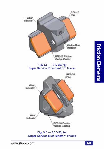
60
Friction
Elem
ents
www.stucki.com
Fig. 3.6 — RFE-53, for Super Service Ride Master Trucks
Fig. 3.5 — RFE-26, for Super Service Ride Control Trucks

61
Fri
ctio
n E
lem
ents
www.stucki.com
Fig. 3.7 — Wear Indicator Side View (Most Wedges)

62
Friction
Elem
ents
www.stucki.com
Yard Inspection
Inspect wear indicators on the vertical face of the wedge. Replace wedges when the wear indicators are no longer visible. New wedges will have approximately 3/8” of wear indicator visible. A mustache gage can be used to check wedge rise. Wedge rise limits for RFEs are the same as for the all-metal friction shoes they replace (see AAR Field Manual, Rule 88). For the RFE-18 and RFE-26, wedge rise is excessive when the hole on the front of the casting is entirely above the top plate of the bolster. The RFE-16 wedge rise limit indicator is the bottom of the face wear indicator itself.

63
Fri
ctio
n E
lem
ents
www.stucki.com
The upper corners of the RFE-18 and RFE-26 resilient pads may experience splitting. These corner splits normally propagate across the top of the pad, in line with the upper edge of the bolster, and do not affect the performance of the wedge. Cars having pads exhibiting such cracks should not be shopped for pad or wedge replacement.
Check top edge of resilient urethane pads for flush seating against the wedge and bolster pocket. Any pad cracks above the area of contact with the bolster pocket are acceptable and not cause for renewal. The appearance of “stringy” extrusions of pad material between the pad and casting at the top edge could be indicative of severe hunting, and A. Stucki Company should be consulted.

64
Friction
Elem
ents
www.stucki.com
Shop Inspection
In addition to the previous yard inspection procedures, inspection in the repair shop should include the following procedures:
Column Wear Plate: Check closely for cracks, loose or missing fasteners, or excessive wear, and replace as necessary. Plates worn more than 1/8” at any area must be replaced. Column wear plates must be reasonably parallel, and spacing between plates must be in accordance with AAR requirements.
RFE Casting and Resilient Pad: Chipping of casting corners is acceptable. Wedges having sizable pieces missing, or having obvious cracks, must be replaced.

65
Fri
ctio
n E
lem
ents
www.stucki.com
If wedge rise measurements indicate wedges are above condemnable heights, both complete wedges should be replaced. The exception is if resilient pad(s) are severely damaged, and casting has at least 3/16” face wear indicator remaining, then it is acceptable to replace the pads only.
Pry old pads from the casting with a screwdriver, and install new pads by aligning the post on the back of the pad with the hole in the sloped face of the casting. Strike the pad face with a mallet to seat it onto the casting.
Patches of dark, flaky material on the faces of the pads are common, and produce no detrimental effects. This is not cause for renewal.
In the case of the RFE-18, RFE-26, and RFE-53, if cracks emanating from the upper or lower corners of the pads have extended downward toward the center of the pad more than 3/4”, then the cracked pad should be replaced.

66
Friction
Elem
ents
www.stucki.com
Wedge Spring: Broken wedge springs must be replaced. The springs supplied by Stucki for the various RFE models are virtually identical to the springs supplied by the manufacturers of the all-metal wedge systems. Free heights of springs should be checked. Refer to A. Stucki Company’s RFE Installation Instructions for minimum allowable free heights.
Stucki RFEs and all-metal friction wedges should never be combined in the same truck. RFEs must always be replaced in kind.

67
Hyd
rau
lic S
tab
ilize
rs
www.stucki.com
4. Hydraulic Stabilizers
Stucki hydraulic stabilizers are the only hydraulic damping units guaranteed to meet AAR Specification M-965 and Field Manual Rule 50 to ensure safe operation when controlling resonant rocking of high-center-of-gravity cars.
Fig. 4.1 — HS-10

Sid
e Bearin
gs
68
Hyd
raulic S
tabilizers
www.stucki.com
Fig. 4.2 — HydraShox Platinum (HS-7 replacement)
Fig. 4.3 — HS-7100
Note: Available as reconditioned unit only.

69
Hyd
rau
lic S
tab
ilize
rs
www.stucki.com
Yard and Shop Inspection
Hydraulic stabilizers should be positioned vertically upright with the body spring properly seated between the stabilizer body and the bolster. Units not properly positioned or seated on the side frame must be repositioned correctly. If stabilizer body has been damaged due to bolster or side frame lug interference to allow oil leakage at damaged area, unit must be replaced, and the damaged stabilizer should be scrapped.
Stucki hydraulic stabilizers have a sight glass on one side of the reservoir to check for proper operating fluid level. On the HS-7 and Hydrashox Platinum, this window is protected from dirt by a plastic cap, which must be removed to make the visual check. If the cap is missing, clean out any dirt on the surface of the glass. (A sliver of tie wood works well for this task.) Be sure the unit is sitting in its normal upright position when inspecting the sight glass.

Sid
e Bearin
gs
70
Hyd
raulic S
tabilizers
www.stucki.com
f
A. Window Full
Unit OK
C. Empty
Replace ASAP
B. Partially Full
Replace at the next maintenance interval
A flashlight may be helpful in making the sight glass inspection. Figure 4.4 illustrates one of three conditions that may be encountered during inspection.
Fig. 4.4 — Hydraulic Stabilizer Sight Glass Window

71
Hyd
rau
lic S
tab
ilize
rs
www.stucki.com
Condition A. The oil level in the reservoir is full. The entire glass area will appear dark, and the unit should be left in service, regardless of any external sludge accumulation.
Condition B. The oil level has dropped to the sight glass window, and only the upper portion of two shiny rings appears to be reflecting light. This indicates sufficient fluid remaining in the reservoir for adequate operation; however, it is the first warning the unit should be scheduled for replacement when the car is next shopped for routine maintenance. This is not an AAR or FRA defect as far as foreign cars are concerned. For systems cars, however, it is advisable to replace when this condition is found.

Sid
e Bearin
gs
72
Hyd
raulic S
tabilizers
www.stucki.com
Condition C. The oil level has dropped below the sight glass area, and the two shiny rings are completely visible. The unit should be replaced as soon as possible. This condition constitutes a viable AAR or FRA defect.
Stucki hydraulic stabilizers incorporate a low pressure seal on the piston rod, which will gradually, but continually pass slight amounts of oil under normal operating conditions. This fluid loss is compensated for by the reserve oil. The appearance of external oil/sludge accumulation is not an indication of a defective unit.

73
Hyd
rau
lic S
tab
ilize
rs
www.stucki.com
HS-7 and HS-7100 units removed on account of low oil level should be returned to:
A. Stucki Company2155 Allen Street Extension
Falconer, NY 14733
Please call 716.665.5217 in advance for a required delivery appointment.
The piston rods should be protected from damage in transit by use of the protective sleeve provided on the rod of the new replacement unit.
HS-10s are not able to be rebuilt and should be replaced in kind. HS-6s have been discontinued and should be replaced by HydraShox Platinum Series. Once reserve oil has been depleted, HS-6s should be discarded.

74
Sid
e Bearin
gs
Intern
ation
al Pro
du
cts
www.stucki.com
5. International Products
A. Stucki Company manufactures several products domestically and off-shore that are designed for specific applications to freight wagons in various countries outside North America. These products, in general, follow the same installation and inspection requirements as those for our conventional domestic products of the same type (section 2.0). For that reason those instructions will not be repeated here, but exceptions to conventional installation or inspection procedures will be noted.

Inte
rnat
ion
al P
rod
uct
s
75www.stucki.com
Australia, New Zealand, and Malaysia Side Bearers
Fig. 5.1 — CCB-2200XT, 2200 Lb. Preload
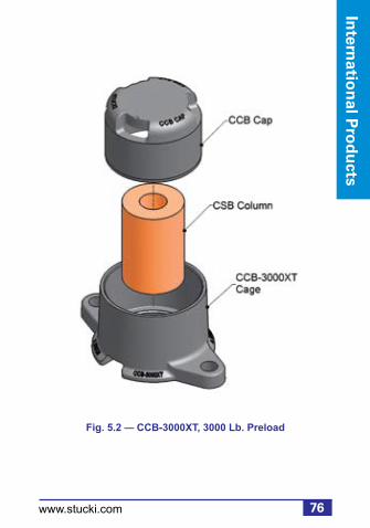
76
Sid
e Bearin
gs
Intern
ation
al Pro
du
cts
www.stucki.com
Fig. 5.2 — CCB-3000XT, 3000 Lb. Preload

Inte
rnat
ion
al P
rod
uct
s
77www.stucki.com
Fig. 5.3 — ISB-2LP, 4500 Lb. Preload
Note: Low profile. See installation exceptions on page 78.

78
Sid
e Bearin
gs
Intern
ation
al Pro
du
cts
www.stucki.com
Installation Exceptions: The ISB-2LP resilient side bearer is designed for use on wagons having insufficient vertical space available at the side bearer location to allow use of the conventional Stucki side bearer models.
The nominal setup height for installing the ISB-2LP is 3-1/16” ± 1/16”, or 78 mm ± 1 mm. At this setup height, the nominal, new compression preload is 4500 pounds.
The ISB-2LP has been used on a limited number of wagons in Sweden, and is also in general use in Malaysia where it has been retrofitted as an upgrade to existing wagons of various types. A few ISB-2LPs have been applied to special purpose cars in the U.S. These applications have primarily been made for noise reduction on business cars.

Inte
rnat
ion
al P
rod
uct
s
79www.stucki.com
675-RXL Side Bearer
Fig. 5.4 — 675-RXL, 2200 Lb. Preload
80
Sid
e Bearin
gs
Intern
ation
al Pro
du
cts
www.stucki.com
The 675-RXL is a low preload version of the standard Stucki resilient, metal-capped 675-RL. The 675-RXL has a preload at 5-1/16” setup height of 2200 pounds (compared to 3000 pounds for the RL). The only physical difference between the two models is the resilient block design.

Inte
rnat
ion
al P
rod
uct
s
81www.stucki.com
656-CRL Side Bearer
Fig. 5.5 — 656-CRL, 3500 Lb. Preload

82
Sid
e Bearin
gs
Intern
ation
al Pro
du
cts
www.stucki.com
The 656-CRL is a low preload version of the standard 656-CR. The 656-CRL has a preload at 5-1/16” setup height of 3500 pounds (preload of the standard 656-CR is 6000 pounds). The only physical difference between the models is the resilient block. 656-CRLs are in use in Australia and New Zealand, and on a number of freight wagons in Malaysia. They are also used in North America on one group of 5-unit 100 ton articulated double stack cars.

Inte
rnat
ion
al P
rod
uct
s
83www.stucki.com
The JOEY Series Side Bearers
For wagons with only mating plates of steel for body and bogie side bearers, a cast pocket was designed that could be retrofit welded into the bogie bolster to contain the Stucki components (to accommodate 5-1/6” setup height). New bogie bolsters can also be cast with this pocket integral. The inside dimensions of the JOEY pocket replicate the inside length and width of the Stucki 656-C single roller side bearing cage with the end closures installed. The proper base contour for seating the resilient blocks and roller is achieved by use of a separate base plate, a casting designed to replicate the inside floor of the Stucki 656-C cage. Thus, the internal components of any standard Stucki model that uses one of our shorter (C length) cages can fit into the JOEY pocket, and the end closures are not required.

84
Sid
e Bearin
gs
Intern
ation
al Pro
du
cts
www.stucki.com
Fig. 5.6 — JOEY Pocket Welded into Bogie Bolster
Fig. 5.7 — Side Bearer Assembly in JOEY Pocket
To distinguish the retrofit element kits for these applications from the element packages for our standard cages (which normally include 5/16” cage end closures), they have been designated as JOEYS.

Inte
rnat
ion
al P
rod
uct
s
85www.stucki.com
Several slightly different versions of the base plate casting have been manufactured, varying in thickness. Regardless of which base plate and pocket casting is used, the normal setup is established by placing a 108 mm high gage block set into the center of the base plate, then lowering the wagon body to the bogie and measuring the clearance to the body side bearer wear plate. From this measurement, determine the amount of shim required to bring the space within 1.5 mm of the top of the gage block. Generally it is advisable when making JOEY pocket applications of the Stucki metal capped side bearings, 675-RL, 675-RXL, or 685-RM, to specify the JOEY element kits to have the RB-27 metal cap. The flat sides of the RB-27 cap provide greater area of engagement with the sides of the JOEY pockets, which results in less wear than if the RB-24 or RB-34 caps are used.
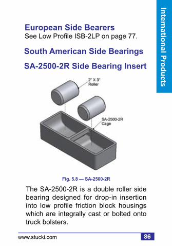
86
Sid
e Bearin
gs
Intern
ation
al Pro
du
cts
www.stucki.com
European Side BearersSee Low Profile ISB-2LP on page 77.
South American Side Bearings
SA-2500-2R Side Bearing Insert
Fig. 5.8 — SA-2500-2R
The SA-2500-2R is a double roller side bearing designed for drop-in insertion into low profile friction block housings which are integrally cast or bolted onto truck bolsters.

Inte
rnat
ion
al P
rod
uct
s
87www.stucki.com
SA-5000-2R Side Bearing Insert
The SA-5000-2R is a double roller side bearing designed for drop-in insertion into friction block housings which are integrally cast or bolted onto truck bolsters.
Roller clearance for both the SA-2500-2R and SA-5000-2R models should be set at 1/4” ± 1/16” (6 mm ± 1 mm) for wagons having 1,435 mm gauge trucks, or at 3/16” ± 1/16”) (5 mm ± 1 mm) for wagons having 1,000 mm (or meter) gauge trucks.
Fig. 5.9 — SA-5000-2R
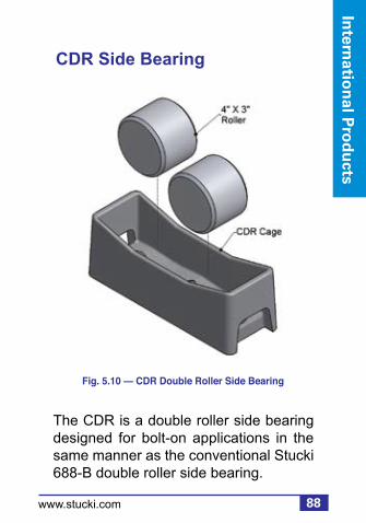
88
Sid
e Bearin
gs
Intern
ation
al Pro
du
cts
www.stucki.com
CDR Side Bearing
The CDR is a double roller side bearing designed for bolt-on applications in the same manner as the conventional Stucki 688-B double roller side bearing.
Fig. 5.10 — CDR Double Roller Side Bearing

Inte
rnat
ion
al P
rod
uct
s
89www.stucki.com
The RFE-3118 was designed to replace the all-metal RC-18 friction wedge used primarily in Ride Control bogies in New Zealand. Castings are currently manufactured in New Zealand. The RFE-3118 utilizes two Stucki RFE-31 resilient pads, which are available through the Stucki sales representative in Australia.
Australia and New Zealand Resilient Friction Elements
RFE-3118 Resilient FrictionElement
Fig. 5.11 — RFE-3118
RFE-31Pads

90
Sid
e Bearin
gs
Intern
ation
al Pro
du
cts
www.stucki.com
The RFE-3234 was designed to replace the all-metal RC-134 friction wedge used primarily in Ride Control bogies in Australia. Castings are currently manufactured in Australia. The RFE-3234 utilizes two Stucki RFE-32 resilient pads, which are available through the Stucki sales representative in Australia.
RFE-3234 Resilient Friction Element
Fig. 5.12 — RFE-3234
RFE-32Pads

Inte
rnat
ion
al P
rod
uct
s
91www.stucki.com
The RFE-3262 was designed to replace the all-metal RC-262 friction wedge used primarily in Ride Control bogies in Australia. Castings are currently manufactured in Australia. The RFE-3262 utilizes two Stucki RFE-32 resilient pads, which are available through the Stucki sales representative in Australia and New Zealand.
RFE-3262 Resilient Friction Element
Fig. 5.13 — RFE-3262
RFE-32Pads

92
Sid
e Bearin
gs
Intern
ation
al Pro
du
cts
www.stucki.com
RFE-4401 Resilient Friction Element
The RFE-4401 was designed to replace the all-metal RC-1 fr ict ion wedge used primarily in Ride Control bogies in Australia. Castings are currently manufactured in Australia. The RFE-4401 utilizes two Stucki RFE-44 resilient pads, which are available through the Stucki sales representative in Australia.
Figure 5.14 — RFE-4401
RFE-44Pads

93
Bra
ke B
eam
s
www.stucki.com
6. Brake Beams
Fig. 6.1 — Reversible Brake Beam
Sid
e Bearin
gs
Brake B
eams
94www.stucki.com
Product Description
Stucki manufactures rugged, fatigue and vibration resistant brake beams to support both composition and cast iron shoes. All brake beams are provided with angle corrected (AC) heads, fixed or replaceable, to optimize brake shoe wear and provide for optimum life. Its durable and lightweight construction provides easy brake shoe inspection and replacement. Hardened pinholes for extended life and safety allow for superior service life. This product can be supplied with a fixed strut (not shown), a fixed head, an easy to use reversible strut, or a replaceable head (RC). Replaceable heads provide significant cost savings as compared to replacing whole beams for damaged heads. Both #18 and #24 sizes are available.

95
Bra
ke B
eam
s
www.stucki.com
Inspection
Replacement of brake beams can be considered for any of the inspection criteria below. Refer to AAR Field Manual of Interchange, Rule 6 for a detailed list of wear limits, gauging, and causes for renewal.
1. Any brake beam parts which are cracked, broken, or missing
2. Damage or wear on brake beam head (heads alone can be replaced in lieu of entire beams – RC beams)
3. Twisted beams (greater than 1 inch when comparing opposite heads against wheels)
4. Worn end extensions
5. Bent or twisted struts
6. Strut pin holes worn 3/16” or more
7. Slot lever worn 1/8” or more

Sid
e Bearin
gs
Brake B
eams
96www.stucki.com
Reversible Brake Beam
Three steps for converting either RH or LH in the field.
First • Use screwdriver to pull retainer & pin (If tight, pin may be pushed from the opposite end, by the screwdriver).
Second• Insert steel bar in strut lever slot.• Tilt rotating strut 90 degrees, until the slots in end casting match slots in strut.
Third• Re-insert pin with groove end last.• Reapply retainer by hand at pin groove (push it safely in place with screwdriver).

97
Bra
ke B
eam
s
www.stucki.com
Fig. 6.2 — Strut and Pin
Pin
Retainer
StrutLeverSlot

Sid
e Bearin
gs
Brake B
eams
98www.stucki.com
Replaceable Head Procedure
1. Remove damaged head from brake beam assembly from the side of
the car.2. Position replaceable head to align holes.3. Insert bolt through replaceable head
and beam assembly combined. Apply washer assembly (large washer first, small washer next), and lock nut to threaded bolt. Tighten lock nut until orange capsule breaks (or 300 ft-lbs equivalent).
4. Install brake shoe and return to service.
Fig. 6.3 — Replaceable Brake Beam Head

99
Rec
on
dit
ion
ing
Ser
vice
s
www.stucki.com
Draft Gear
Independent Draft Gear, a division of A. Stucki Company, reconditions, tests, and pins the most commonly available draft gear per AAR M-901B Specifications. Refer to AAR Interchange Rule 21, Section B, Groups J & M for an overview of the draft gear models that we recondition.
Other g roup type gears can be reconditioned and used for captive service.
7. Reconditioning Services

100
Reco
nd
ition
ing
Services
www.stucki.com
Inspection
Reconditioning of a draft gear can be considered when any of the defects listed in Secton A of the AAR Field Manual Rule 21 are present. Refer to the manual for a detailed list of wear limits, gauging, and cause for renewal.
Also, refer to manufacturer’s specifications for In-Car and Out-of-Car inspection requirements for each individual model.
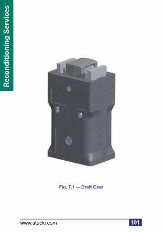
101
Rec
on
dit
ion
ing
Ser
vice
s
www.stucki.com
Fig. 7.1 — Draft Gear

102
Reco
nd
ition
ing
Services
www.stucki.com
Date Classification
The original manufacture date or last reconditioning date should be located on the draft gear case. Per AAR Field Manual Rule 21, draft gear must be:
• Reconditioned after 16 years from the date of original manufacture, or 10 years from the last recondition date. Should a date not be readily apparent on the case, the gear must be reconditioned.
• Tested and pinned if the gear is less than 16 years old or has been reconditioned within the last 10 years.
• Pinned only if the gear was manufactured or tested within the last 10 years.

103
Rec
on
dit
ion
ing
Ser
vice
s
www.stucki.com
Friction Component Classification:
Irrespective of the gear’s date classification, a gear must be reconditioned if any of its friction components are broken, damaged in any way, or missing.
Gears are c lass i f ied as FC/C/D ( F r i c t i o n C o m p o n e n t C a s e Damage) per the following criteria:
1. More than 1 broken or missing friction component 2. Center wedge is damaged 3. The gear is stuck in a compressed position

104
Reco
nd
ition
ing
Services
www.stucki.com
Case Classification: As in the case of friction component damage, a draft gear must be rebuilt if the case has been subject to excessive wear or is damaged. Gears with cases that meet the following are also considered FC/C/D:
1. Wall thickness – visibly worn case wall 2. Torch cut – 1 inch or more
Scrap Classification: Gears with bulges, split cases or cracks in excess of 2 inches cannot be repaired and are classified as scrap. Also, gears not listed on the IDG list of acceptable gears (detailed list can be found at www.draft-gear.com) are either not reconditionable or are obsolete and therefore classified as scrap.

105
Rec
on
dit
ion
ing
Ser
vice
s
www.stucki.com
Gears which meet the cri teria for reconditioning should be shipped to:
Independent Draft Gear1000 Martin Luther King Jr. Blvd.
Farrell, PA 16121Phone: 724.981.2251
Fax: 724.981.2256

106
Reco
nd
ition
ing
Services
www.stucki.com
Repair Services
American Industries, Inc. provides railcar repair and reconditioning services to the railroad industry. We also provide new, secondhand, gauged, and reconditioned railroad parts. Facilities in Sharon, PA are certified under AAR M-212 and M-214, as well as QA certification M-1003.
Reconditioning services include:• Wheel Sets• Air Brakes• Bolsters• Sideframes• Couplers• Yokes• Draft Gears• Complete Truck Assemblies
Secondhand parts include:• Air Brake Parts• Couplers• Yokes

107
Rec
on
dit
ion
ing
Ser
vice
s
www.stucki.com
New parts include:• Air Brake Parts (manufactured by New York Air Brake)
American Industries is certified to reprofile freight car and locomotive wheel sets to any profile. American Industries is also AAR certif ied for mounting new or reconditioned roller bearings.
Also provides interchange usable or second hand repairable axles and roller bearings at competitive prices.

Sid
e Bearin
gs
Pro
du
ct Ind
ex
108www.stucki.com
Product Index
656-C ................................................. 28656-CR .............................................. 17656-CRH............................................ 20656-CRL ............................................ 81656-SLB............................................. 27675-RL ............................................... 21675-RXL ............................................ 79685-RM .............................................. 22688-B ................................................. 29688-BR .............................................. 18690-RL ............................................... 19BUS-18-BRAC-CHL .......................... 93BUS-18-BRAC-CHR ......................... 93BUS-18-LRRC-CHL ........................... 93BUS-18-LRRC-CHR .......................... 93 BUS-24-BRAC-CHL .......................... 93BUS-24-BRAC-CHR .......................... 93 BUS-24-LRRC-CHL ........................... 93BUS-24-LRRC-CHR .......................... 93 CCB-2200XT ..................................... 75CCB-3000XT ..................................... 76CCB-4500XT ....................................... 9CCB-6000XT ....................................... 9

109
Pro
du
ct In
dex
www.stucki.com
Product Index (continued)
CDR ................................................... 88CSB® .................................................... 8 HS-7 .................................................. 68HS-10 ................................................ 67HS-7100 ............................................ 68HydraShox Platinum Series............... 68ISB-2LP ............................................. 77ISB-9DR ............................................ 23ISB-9DRL .......................................... 24ISB-10................................................ 25ISB-12................................................ 26JOEY ................................................. 83RetroXT 4500 .................................... 16RetroXT 5400B .................................. 14RetroXT 5400C .................................. 15RetroXT LP Bolt-On ........................... 10RetroXT LP Drop-In ............................11RetroXT LPC ..................................... 12RetroXT SP ....................................... 13RFE-16 .............................................. 58RFE-18 .............................................. 59

Sid
e Bearin
gs
Pro
du
ct Ind
ex
110www.stucki.com
Product Index (continued)
RFE-26 .............................................. 60RFE-41 .............................................. 58RFE-51 .............................................. 59RFE-53 .............................................. 60RFE-3118 .......................................... 89RFE-3234 .......................................... 90RFE-3262 .......................................... 91RFE-4401 .......................................... 92SA-2500-2R ....................................... 86SA-5000-2R ....................................... 87SSB® .................................................... 7
Ride Control, Super Service Ride Control, Low Level Ride Control, and Super Service Ridemaster are federally registered trade marks of ASF-Keystone, Inc. Barber is a federally registered trade mark of Barber, Inc. Miner is a federally registered trade mark of Miner Enterprise, Inc. Cardwell-Westinghouse is a federally registered trade mark of Wabtec Corporation.


113
Rec
on
dit
ion
ing
Ser
vice
s
www.stucki.com
2600 Neville Road, Pittsburgh, PA 15225 412.771.7300, Fax: 412.771.7308
In Australia: GEMCO 61 8 9454 9666
In Brazil: A. Stucki do Brasil Ltda +55 (11) 3842 4630
www.stucki.com email: [email protected]
Improving Ride Quality Since 1911