Embed Size (px)
Citation preview
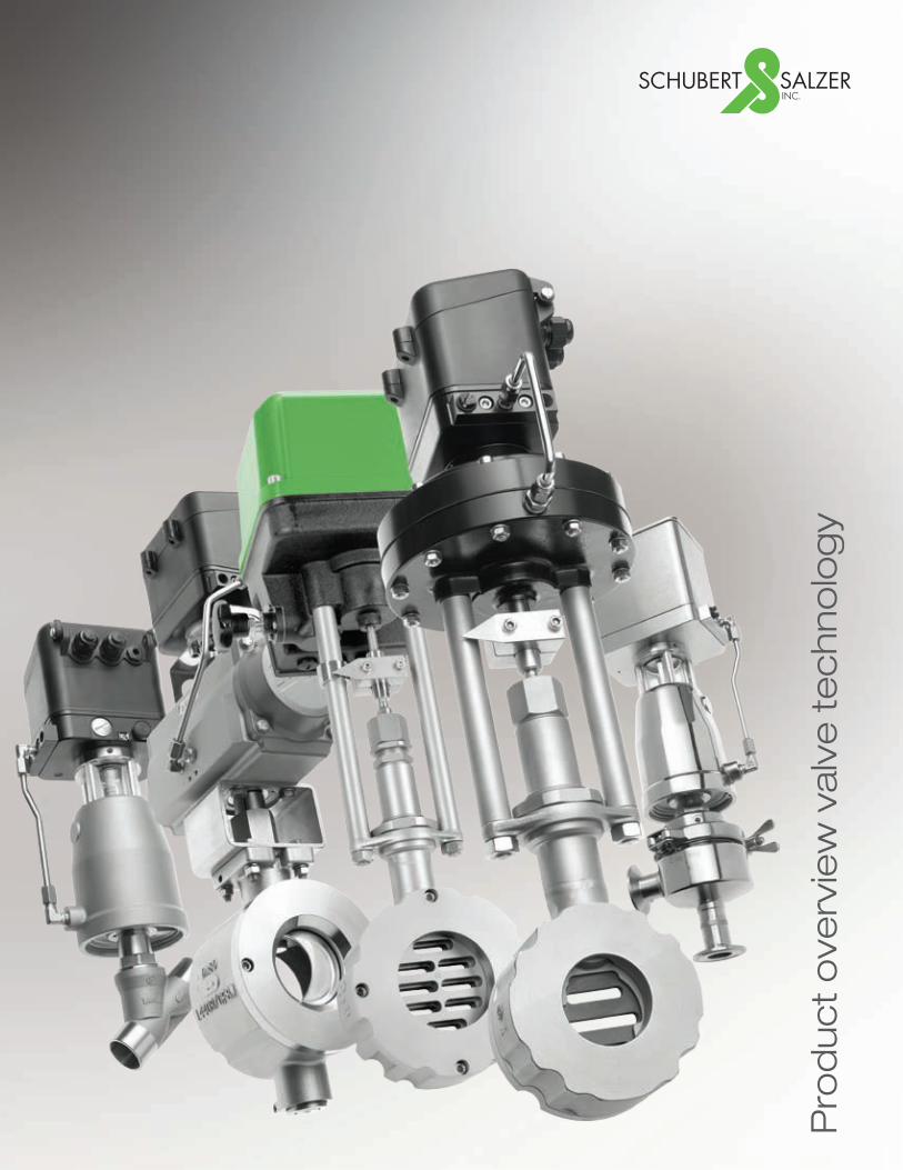
Pro
du
ct
ove
rvie
w v
alv
e t
ec
hn
olo
gy
2
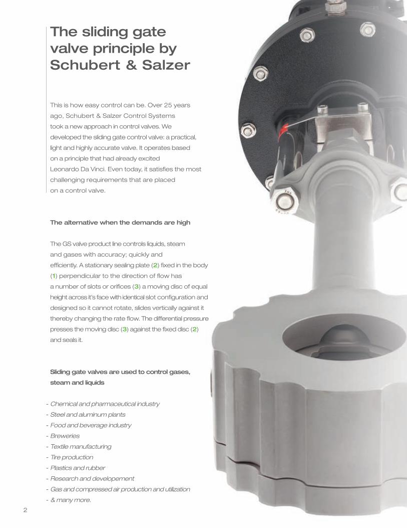
This is how easy control can be. Over 25 years
ago, Schubert & Salzer Control Systems
took a new approach in control valves. We
developed the sliding gate control valve: a practical,
light and highly accurate valve. It operates based
on a principle that had already excited
Leonardo Da Vinci. Even today, it satisfies the most
challenging requirements that are placed
on a control valve.
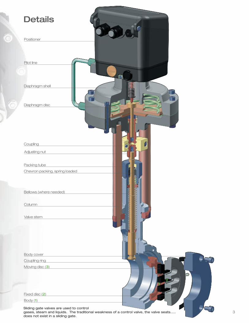
The alternative when the demands are high
The GS valve product line controls liquids, steam
and gases with accuracy; quickly and
efficiently. A stationary sealing plate (2) fixed in the body
(1) perpendicular to the direction of flow has
a number of slots or orifices (3) a moving disc of equal
height across it’s face with identical slot configuration and
designed so it cannot rotate, slides vertically against it
thereby changing the rate flow. The differential pressure
presses the moving disc (3) against the fixed disc (2)
and seals it.
Sliding gate valves are used to control gases,
steam and liquids
Chemical and pharmaceutical industry
Steel and aluminum plants
Food and beverage industry
Breweries
Textile manufacturing
Tire production
Plastics and rubber
Research and developement
Gas and compressed air production and utilization
& many more.
-
-
-
-
-
-
-
-
-
-
The sliding gatevalve principle bySchubert & Salzer
3
Positioner
Pilot line
Diaphragm shell
Diaphragm disc
Coupling
Packing tube
Bellows (where needed)
Column
Valve stem
Body cover
Coupling ring
Moving disc (3)
Body (1)
Fixed disc (2)
Adjusting nut
Chevron packing, spring loaded
23
Details
Sliding gate valves are used to controlgases, steam and liquids. The traditional weakness of a control valve, the valve seats.....does not exist in a sliding gate.
4
Fits into tight spaces
Compact construction for minimum use of space
and ease of installation
Variable CV values
A simple exchange of the fixed disc (plate) is all
that‘s needed to change the CV value at any time -
possible range of CV = 0.05 to 1056
Extremely low leakage rate
< 0.0001% of the CV value due to the self-lapping
action of the moving disc and the pressure
of the medium against the moving disc, using a
surface seal instead of an annular seal.
Outstanding rangeability
Up to 160:1
The advantages ofsliding gate valves
Standard packing environmentally safe
Schubert & Salzer‘s standard packing is
certified by the TUV to comply with the
German TA-Luft-standard which limits valve
packing emissions. The applied testing
procedure verifies if the tested sealing
design is equivalent to a bellows solution.
The measured leakage rate (after 150,000
full valve cycles) was 8E-8 mbar I/s and is far
below the allowale leakage standard of
4.7E-6 mbar l/s.
Optimal flow control
Avoids cavitation problems in the valve and
operates quietly by reducing turbulence
Easy to install and maintain
Thanks to the compact construction, the low
weight and the innovative seal disc design
makes easy work of installation
and maintenance.
Minimal wear
Low turbulence means less erosion. The short
stroke (1/4” to 1/2”) insures greater packing life and
also requires reduced actuation energy.
High differential pressures
Using its unique compact design and low energy
consumption, the GS valve gives accurate
control of high differential pressures up to 1450 psi
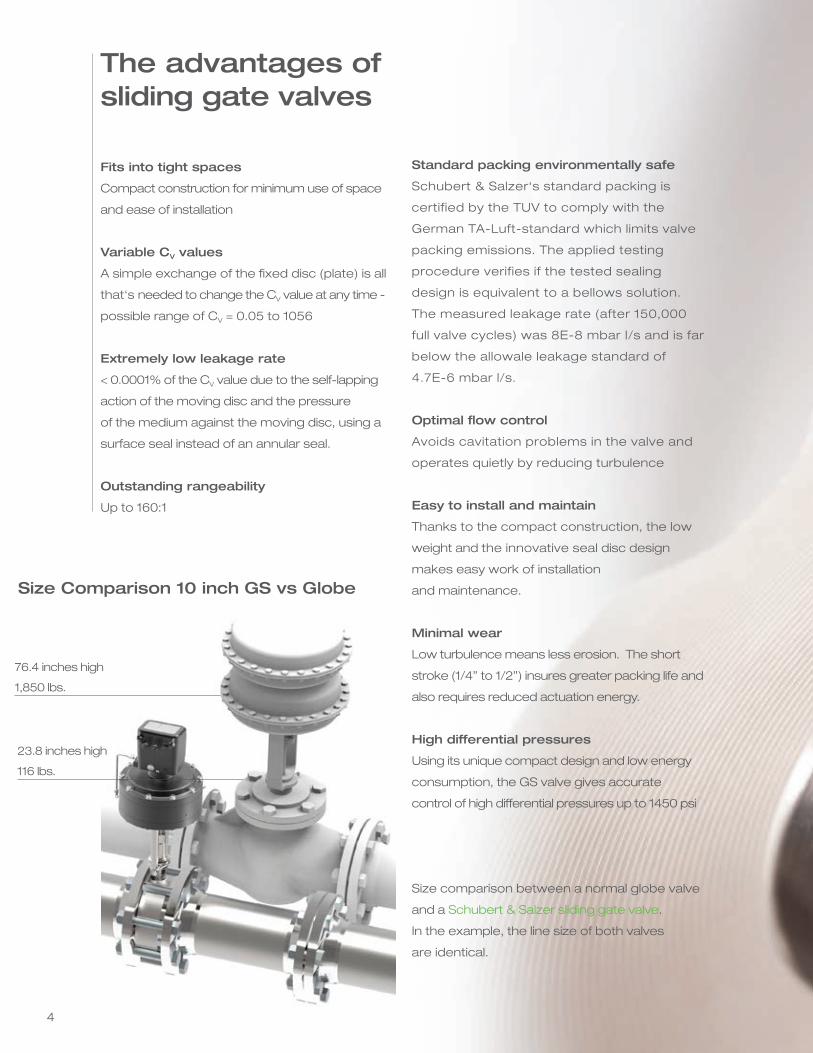
Size comparison between a normal globe valve
and a Schubert & Salzer sliding gate valve.
In the example, the line size of both valves
are identical.
76.4 inches high
1,850 lbs.
23.8 inches high
116 lbs.
Size Comparison 10 inch GS vs Globe
55
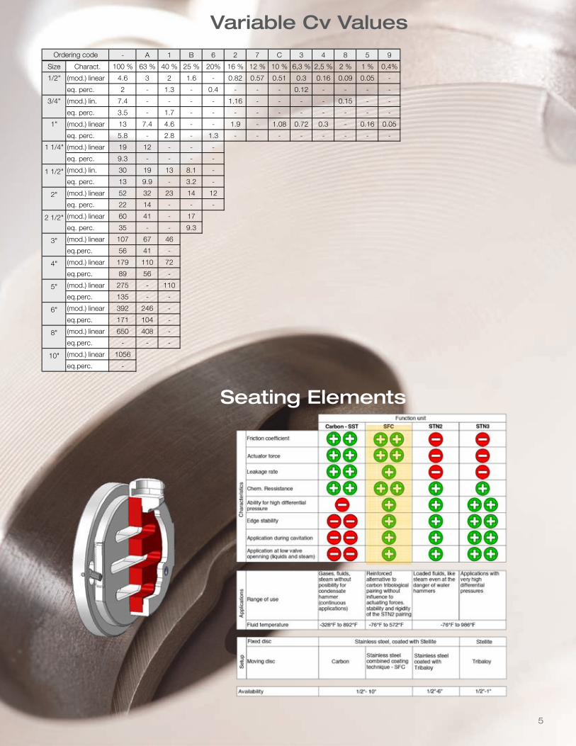
Cv - Values
- A 1 B 6 2 7 C 3 4 8 5 9
Size Charact. 100 % 63 % 40 % 25 % 20% 16 % 12 % 10 % 6,3 % 2,5 % 2 % 1 % 0,4%
1/2" (mod.) linear 4.6 3 2 1.6 - 0.82 0.57 0.51 0.3 0.16 0.09 0.05 -
eq. perc. 2 - 1.3 - 0.4 - - - 0.12 - - - -
3/4" (mod.) lin. 7.4 - - - - 1.16 - - - - 0.15 - -
eq. perc. 3.5 - 1.7 - - - - - - - - - -
1" (mod.) linear 13 7.4 4.6 - - 1.9 - 1.08 0.72 0.3 - 0.16 0.05
eq. perc. 5.8 - 2.8 - 1.3 - - - - - - - -
1 1/4" (mod.) linear 19 12 - - -
eq. perc. 9.3 - - - -
1 1/2" (mod.) lin. 30 19 13 8.1 -
eq. perc. 13 9.9 - 3.2 -
2" (mod.) linear 52 32 23 14 12
eq. perc. 22 14 - - -
2 1/2" (mod.) linear 60 41 - 17
eq. perc. 35 - - 9.3
3" (mod.) linear 107 67 46
eq.perc. 56 41 -
4" (mod.) linear 179 110 72
eq.perc. 89 56 -
5" (mod.) linear 275 - 110
eq.perc. 135 - -
6" (mod.) linear 392 246 -
eq.perc. 171 104 -
8" (mod.) linear 650 408 -
eq.perc. - - -
10" (mod.) linear 1056
eq.perc. -
Ordering code
Variable Cv Values
Seating Elements
6
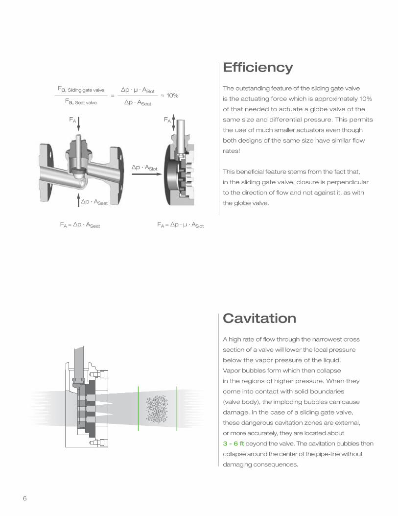
The outstanding feature of the sliding gate valve
is the actuating force which is approximately 10%
of that needed to actuate a globe valve of the
same size and differential pressure. This permits
the use of much smaller actuators even though
both designs of the same size have similar flow
rates!
This beneficial feature stems from the fact that,
in the sliding gate valve, closure is perpendicular
to the direction of flow and not against it, as with
the globe valve.
Efficiency
A high rate of flow through the narrowest cross
section of a valve will lower the local pressure
below the vapor pressure of the liquid.
Vapor bubbles form which then collapse
in the regions of higher pressure. When they
come into contact with solid boundaries
(valve body), the imploding bubbles can cause
damage. In the case of a sliding gate valve,
these dangerous cavitation zones are external,
or more accurately, they are located about
3 - 6 ft beyond the valve. The cavitation bubbles then
collapse around the center of the pipe-line without
damaging consequences.
Cavitation
Fa, Sliding gate valve
Fa, Seat valve
=∆p · μ · ASlot
∆p · ASeat
≈ 10%
FA FA
FA = ∆p · ASeat FA = ∆p · μ · ASlot
∆p · ASlot
∆p · ASeat
7 7
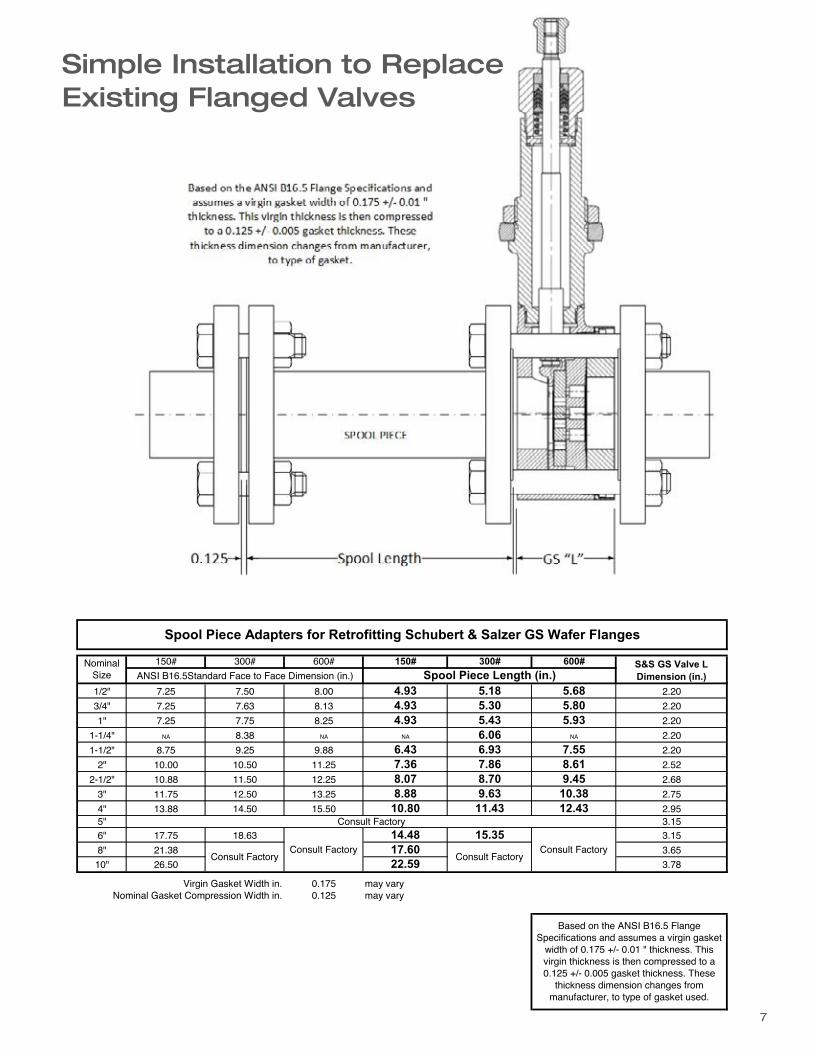
150# 300# 600# 150# 300# 600#
1/2" 7.25 7.50 8.00 4.93 5.18 5.68 2.203/4" 7.25 7.63 8.13 4.93 5.30 5.80 2.201" 7.25 7.75 8.25 4.93 5.43 5.93 2.20
1-1/4" NA 8.38 NA NA 6.06 NA 2.201-1/2" 8.75 9.25 9.88 6.43 6.93 7.55 2.20
2" 10.00 10.50 11.25 7.36 7.86 8.61 2.522-1/2" 10.88 11.50 12.25 8.07 8.70 9.45 2.68
3" 11.75 12.50 13.25 8.88 9.63 10.38 2.754" 13.88 14.50 15.50 10.80 11.43 12.43 2.955" 3.156" 17.75 18.63 14.48 15.35 3.158" 21.38 17.60 3.6510" 26.50 22.59 3.78
0.175 may vary0.125 may vary
GR Aug 2016
Based on the ANSI B16.5 Flange Specifications and assumes a virgin gasket
width of 0.175 +/- 0.01 " thickness. This virgin thickness is then compressed to a 0.125 +/- 0.005 gasket thickness. These
thickness dimension changes from manufacturer, to type of gasket used.
Virgin Gasket Width in.Nominal Gasket Compression Width in.
S&S GS Valve L Dimension (in.)
Consult FactoryConsult Factory
Spool Piece Adapters for Retrofitting Schubert & Salzer GS Wafer Flanges
Nominal Size Spool Piece Length (in.)ANSI B16.5Standard Face to Face Dimension (in.)
Consult Factory
Consult FactoryConsult Factory
Simple Installation to Replace Existing Flanged Valves
8
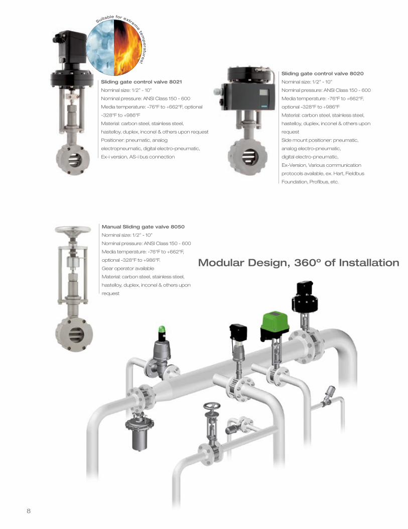
Sliding gate control valve 8021
Nominal size: 1/2” - 10”
Nominal pressure: ANSI Class 150 - 600
Media temperature: -76°F to +662°F, optional
-328°F to +986°F
Material: carbon steel, stainless steel,
hastelloy, duplex, inconel & others upon request
Positioner: pneumatic, analog
electropneumatic, digital electro-pneumatic,
Ex-i version, AS-i bus connection
Sliding gate control valve 8020
Nominal size: 1/2” - 10”
Nominal pressure: ANSI Class 150 - 600
Media temperature: -76°F to +662°F,
optional -328°F to +986°F
Material: carbon steel, stainless steel,
hastelloy, duplex, inconel & others upon
request
Side mount positioner: pneumatic,
analog electro-pneumatic,
digital electro-pneumatic,
Ex-Version, Various communication
protocols available, ex. Hart, Fieldbus
Foundation, Profibus, etc.
Suitable for extreme te
mp
era
ture
s!
Manual Sliding gate valve 8050
Nominal size: 1/2” - 10”
Nominal pressure: ANSI Class 150 - 600
Media temperature: -76°F to +662°F,
optional -328°F to +986°F.
Gear operator available
Material: carbon steel, stainless steel,
hastelloy, duplex, inconel & others upon
request
Modular Design, 360º of Installation
99
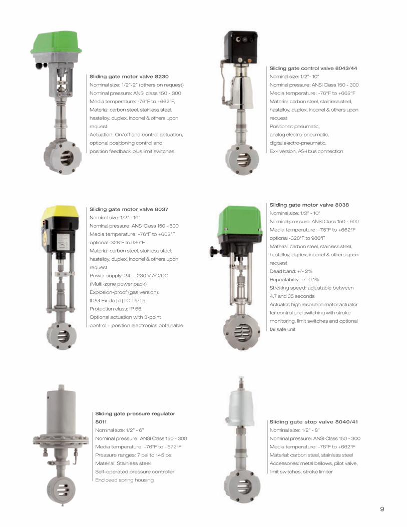
Sliding gate control valve 8043/44
Nominal size: 1/2”- 10”
Nominal pressure: ANSI Class 150 - 300
Media temperature: -76°F to +662°F
Material: carbon steel, stainless steel,
hastelloy, duplex, inconel & others upon
request
Positioner: pneumatic,
analog electro-pneumatic,
digital electro-pneumatic,
Ex-i version, AS-i bus connection
Sliding gate motor valve 8038
Nominal size: 1/2” - 10”
Nominal pressure: ANSI Class 150 - 600
Media temperature: -76°F to +662°F
optional -328°F to 986°F
Material: carbon steel, stainless steel,
hastelloy, duplex, inconel & others upon
request
Dead band: +/- 2%
Repeatability: +/- 0,1%
Stroking speed: adjustable between
4,7 and 35 seconds
Actuator: high resolution motor actuator
for control and switching with stroke
monitoring, limit switches and optional
fail safe unit
Sliding gate stop valve 8040/41
Nominal size: 1/2” - 8”
Nominal pressure: ANSI Class 150 - 300
Media temperature: -76°F to +662°F
Material: carbon steel, stainless steel
Accessories: metal bellows, pilot valve,
limit switches, stroke limiter
Sliding gate motor valve 8037
Nominal size: 1/2” - 10”
Nominal pressure: ANSI Class 150 - 600
Media temperature: -76°F to +662°F
optional -328°F to 986°F
Material: carbon steel, stainless steel,
hastelloy, duplex, inconel & others upon
request
Power supply: 24 ... 230 V AC/DC
(Multi-zone power pack)
Explosion-proof (gas version):
II 2G Ex de [ia] IIC T6/T5
Protection class: IP 66
Optional actuation with 3-point
control + position electronics obtainable
Sliding gate pressure regulator
8011
Nominal size: 1/2” - 6”
Nominal pressure: ANSI Class 150 - 300
Media temperature: -76°F to +572°F
Pressure ranges: 7 psi to 145 psi
Material: Stainless steel
Self-operated pressure controller
Enclosed spring housing
Sliding gate motor valve 8230
Nominal size: 1/2”-2” (others on request)
Nominal pressure: ANSI class 150 - 300
Media temperature: -76°F to +662°F,
Material: carbon steel, stainless steel,
hastelloy, duplex, inconel & others upon
request
Actuation: On/off and control actuation,
optional positioning control and
position feedback plus limit switches
Modular Design, 360º of Installation
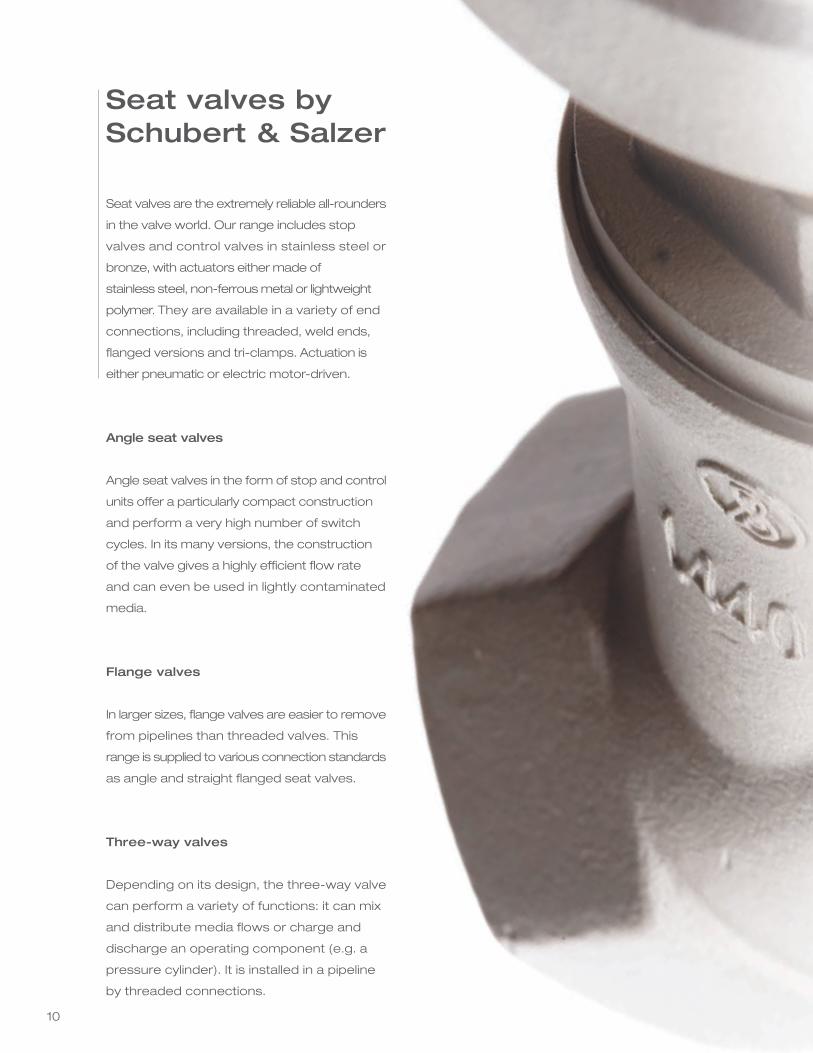
Seat valves are the extremely reliable all-rounders
in the valve world. Our range includes stop
valves and control valves in stainless steel or
bronze, with actuators either made of
stainless steel, non-ferrous metal or lightweight
polymer. They are available in a variety of end
connections, including threaded, weld ends,
flanged versions and tri-clamps. Actuation is
either pneumatic or electric motor-driven.
Angle seat valves
Angle seat valves in the form of stop and control
units offer a particularly compact construction
and perform a very high number of switch
cycles. In its many versions, the construction
of the valve gives a highly efficient flow rate
and can even be used in lightly contaminated
media.
Flange valves
In larger sizes, flange valves are easier to remove
from pipelines than threaded valves. This
range is supplied to various connection standards
as angle and straight flanged seat valves.
Three-way valves
Depending on its design, the three-way valve
can perform a variety of functions: it can mix
and distribute media flows or charge and
discharge an operating component (e.g. a
pressure cylinder). It is installed in a pipeline
by threaded connections.
Seat valves bySchubert & Salzer
10
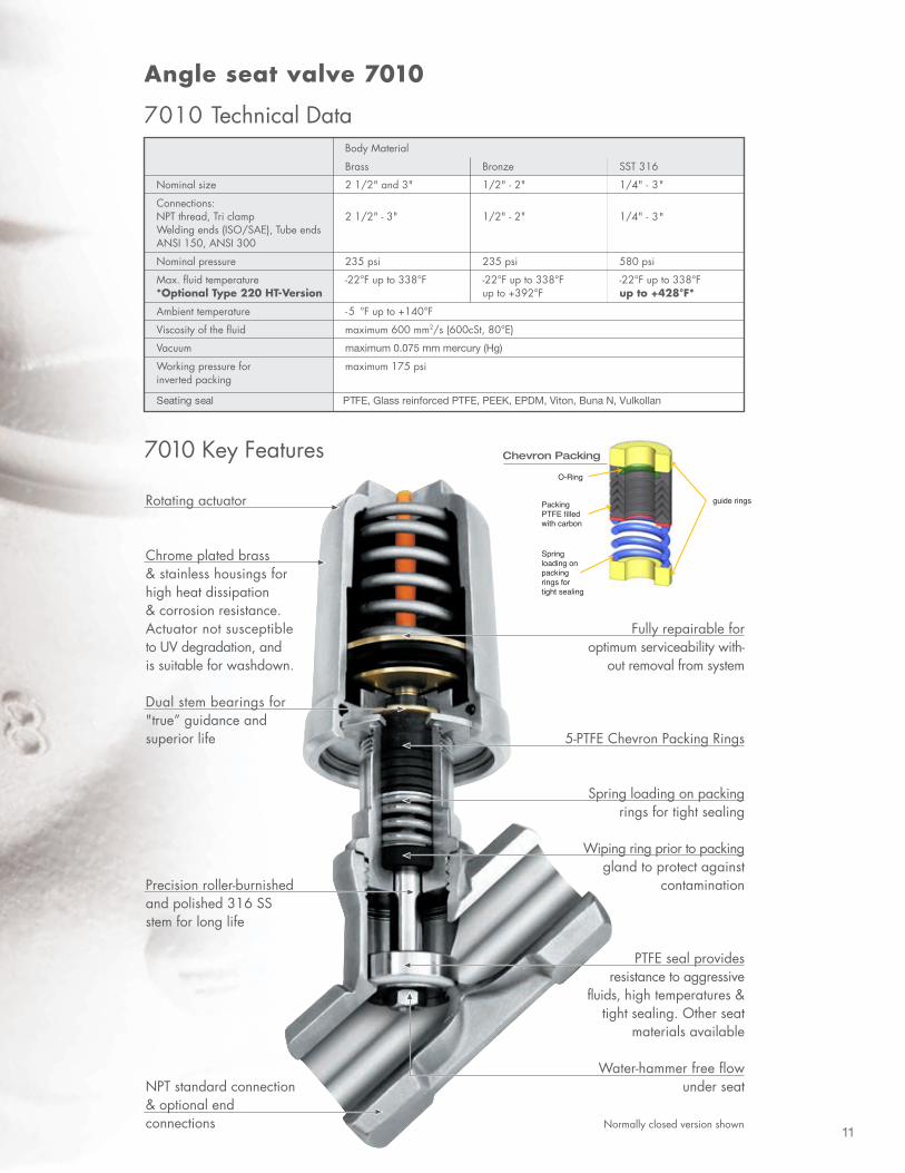
11
Technical Information
3/2 - Way Control Valve 7082with integrated positioner
Materials
with digital positionerType 8049
3/2 - Way Motor Control Valve
Technical Information Valve
Technical Information Motor Actuator
7282
Nominal sizes 1/2" up to 2"
Connections NPT thread: 1/2" up to 2"
Nominal pressure 580 psi
Fluid temperature -22°F up to + 392°F
iT 613 / L 613 leets sselniatSydoB
Seating seal PTFE
)"3 Ø rotautca( detalp emorhc ssarBtennoB
Aluminium (actuator Ø 5")
Diaphragm actuator stainless steel 1.4301
Actuator springs Stainless steel ASTM A313 302 (actuator Ø 3", 10")
Spring steel wire C, zinc coated (actuator Ø 5")
Packing PTFE (carbon filled), spring ASTM A313 302
Valve stem Stainless steel 316 Ti, roller burnished
Position indicator PA Trogamid (clear)
Body materials Stainless steel 316L
Nominal sizes 1/2" up to 1 1/2"
Connections NPT thread: 1/2" up to 1 1/2"
Nominal pressure 580 psi
Fluid temperature -22°F up to + 392°F
Type of motor
Function
Nominal voltage
Set point
Load
Position feedback
external load
limit switches
max. switching load
Power consumption
Stroking time (standard)
Thrust
Class of protection
Ambient temperature
BM24C BM24C/I
Control Control
24 V AC/DC 24 V AC/DC
2 - 10 V 4 - 20 mA
100 kOhm 500 Ohm
2 - 10 V 2 - 10 V
- -
- -
- -
3 W 3 W
3.5s per 3.5s per 0.04inch 0.04inch
BM24C/IOS2 BM250C/IO2
Control Control
20-30V AC 85-250V AC 20-45V DC 120-250V DC
4 - 20 mA 4 - 20 mA
500 Ohm 500 Ohm
4 - 20 mA 4 - 20 mA
< 700 Ohm < 700 Ohm
2 x 2 x
24V AC/DC 24V AC/DC
BM115 BM230
On/Off On/Off
115 V AC 230 V AC
3-step 3-step
-
-
-
-
-
6 W 6 W
190 s/inch 190 s/inch
BM24
On/Off
24 V AC/DC
3-step
-
-
-
-
-
3 W
190 s/inch
70mA 70mA
3 W 4 W 3.5s per 3.5s per 0.04inch 0.04inch
800 N
IP 65
14°F up to +140°F
Ang
le s
eat
valv
es
Seating seal PTFE, Glass reinforced PTFE, PEEK, EPDM, Viton, Buna N, Vulkollan
maximum 0.075 mm mercury (Hg)
Packing
12
O-Ring
guide rings
Spring loading on packing rings for tight sealing
PackingPTFE filledwith carbon
Chevron Packing
12
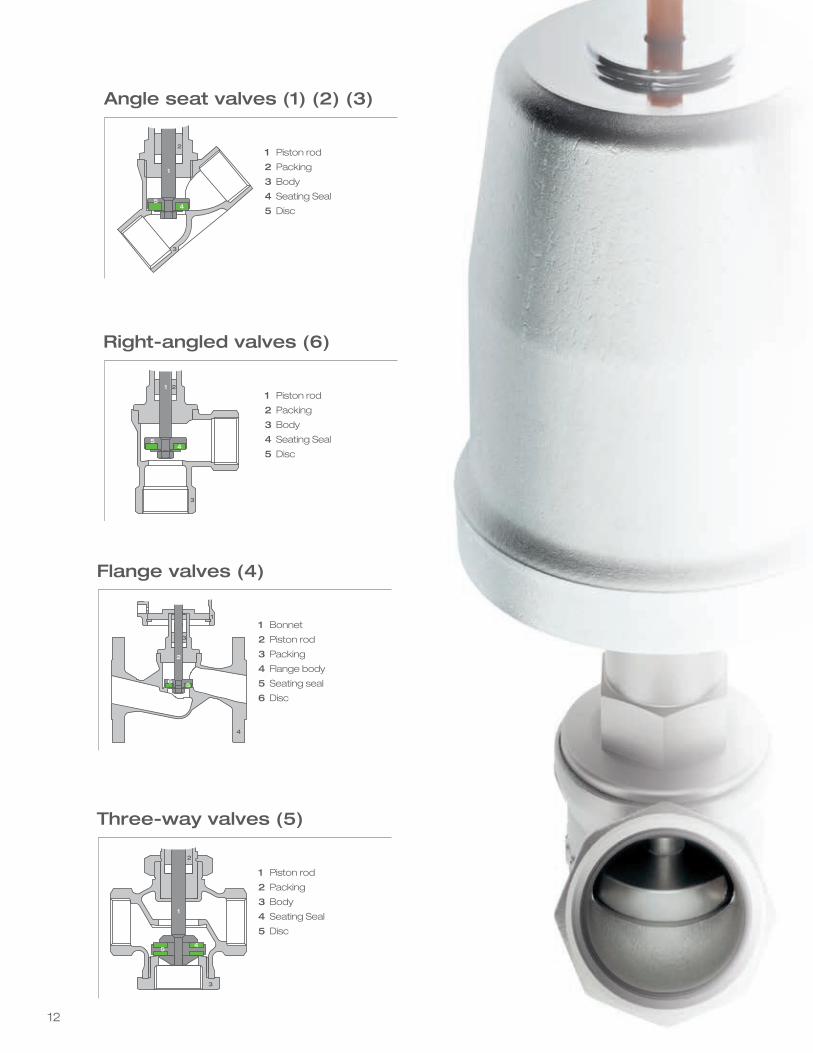
Angle seat valves (1) (2) (3)
1 Piston rod
2 Packing
3 Body
4 Seating Seal
5 Disc
2
3
1
54
Right-angled valves (6)
1 Piston rod
2 Packing
3 Body
4 Seating Seal
5 Disc
1 2
3
54
Flange valves (4)
1 Bonnet
2 Piston rod
3 Packing
4 Flange body
5 Seating seal
6 Disc
Three-way valves (5)
1 Piston rod
2 Packing
3 Body
4 Seating Seal
5 Disc
1
1
3
2
65
4
54
2
3
13
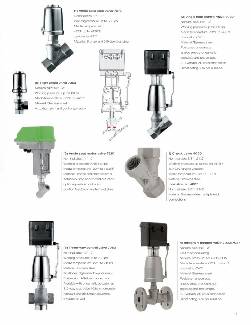
(1) Angle seat stop valve 7010
Nominal size: 1/4” - 3”
Working pressure up to 580 psi
Media temperature:
-22°F up to +428°F,
optional to -74°F
Material: Bronze and 316 stainless steel
(2) Angle seat control valve 7020
Nominal size: 1/4” - 3”
Working pressure up to 250 psi
Media temperature: -22°F to +428°F,
optional to -74°F
Material: Stainless steel
Positioner: pneumatic,
analog electro-pneumatic,
digital electro-pneumatic,
Ex-i version, AS-i bus connection
Direct acting 3-15 psi, 6-30 psi
(3) Angle seat motor valve 7210
Nominal size: 1/4” - 2”
Working pressure: Up to 580 psi
Media temperature: -22°F to +428°F
Material: Bronze and stainless steel
Actuation: stop and control actuation,
optional position control and
position feedback plus limit switches
(5) Three-way control valve 7082
Nominal size: 1/2” - 2”
Working pressure: Up to 232 psi
Media temperature: -22°F to +428°F
Material: Stainless steel
Positioner: digital electro-pneumatic,
Ex-i version, AS-i bus connection
Available with pneumatic actuator as
3/2-way stop valve 7080 in corrosion-
resistant bronze, Motor actuators
available as well
(6) Right angle valve 7050
Nominal size: 1/2” - 2”
Working pressure: Up to 580 psi
Media temperature: -22°F to +428°F
Material: Stainless steel
Actuation: stop and control actuation
4) Integrally flanged valve 7032/7037
Nominal size: 1/2” - 2”
On/Off or Modulating
Nominal pressure: ANSI # 150, DIN
Media temperature: -22°F to +428°F,
optional to -74°F
Material: Stainless steel
Positioner: pneumatic,
analog electro-pneumatic,
digital electro-pneumatic,
Ex-i version, AS-i bus connection
Direct acting 3-15 psi, 6-30 psi
1) Check valve 4000
Nominal size: 3/8” - 2 1/2”
Working pressure: up to 580 psi, ANSI #
150, DIN flanged versions
Media temperature: -4°F to +392°F
Material: Stainless steel
Line strainer 4005
Nominal size: 3/8” - 2 1/2”
Material: Stainless steel, multiple end
connections
1614
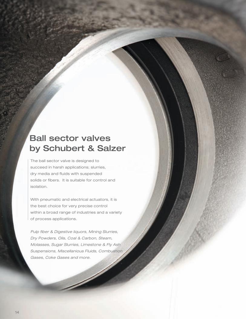
The ball sector valve is designed to
succeed in harsh applications; slurries,
dry media and fluids with suspended
solids or fibers. It is suitable for control and
isolation.
With pneumatic and electrical actuators, it is
the best choice for very precise control
within a broad range of industries and a variety
of process applications.
Pulp fiber & Digestive liquors, Mining Slurries,
Dry Powders, Oils, Coal & Carbon, Steam,
Molasses, Sugar Slurries, Limestone & Fly Ash
Suspensions, Miscellanious Fluids, Combustion
Gases, Coke Gases and more.
Ball sector valves by Schubert & Salzer
15
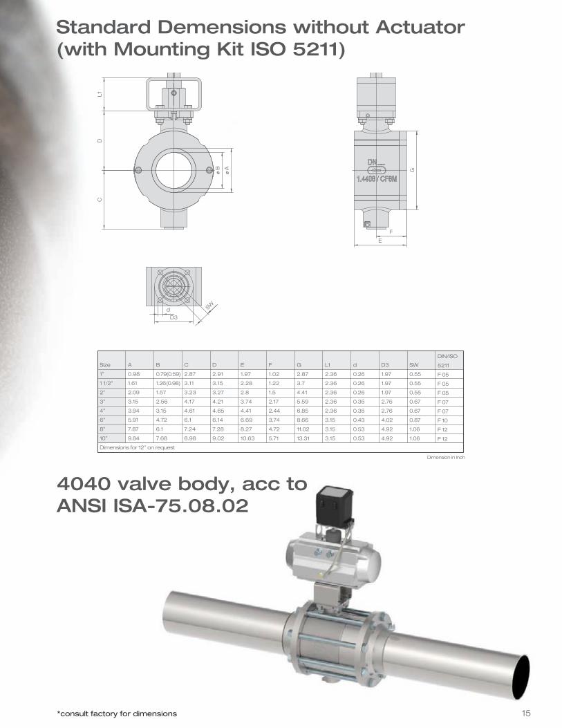
Dimensions without Actuator(with Mounting Kit ISO 5211)
Size
1”
1 1/2”
2”
3”
4”
6”
8”
10”
Dimensions for 12” on request
A
0.98
1.61
2.09
3.15
3.94
5.91
7.87
9.84
B
0.79(0.59)
1.26(0.98)
1.57
2.56
3.15
4.72
6.1
7.68
C
2.87
3.11
3.23
4.17
4.61
6.1
7.24
8.98
D
2.91
3.15
3.27
4.21
4.65
6.14
7.28
9.02
E
1.97
2.28
2.8
3.74
4.41
6.69
8.27
10.63
F
1.02
1.22
1.5
2.17
2.44
3.74
4.72
5.71
G
2.87
3.7
4.41
5.59
6.85
8.66
11.02
13.31
L1
2.36
2.36
2.36
2.36
2.36
3.15
3.15
3.15
d
0.26
0.26
0.26
0.35
0.35
0.43
0.53
0.53
D3
1.97
1.97
1.97
2.76
2.76
4.02
4.92
4.92
SW
0.55
0.55
0.55
0.67
0.67
0.87
1.06
1.06
DIN/ISO
5211
F 05
F 05
F 05
F 07
F 07
F 10
F 12
F 12
Dimension in inch
4040 valve body, acc to ANSI ISA-75.08.02
Standard Demensions without Actuator(with Mounting Kit ISO 5211)
*consult factory for dimensions
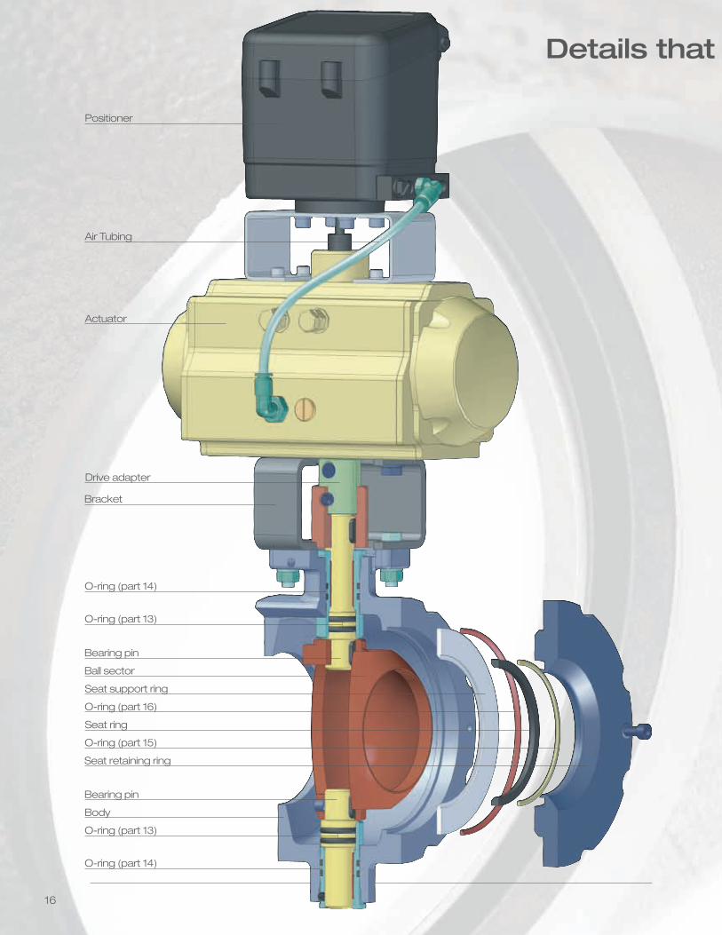
16
Positioner
Air Tubing
Drive adapter
Bracket
Actuator
O-ring (part 14)
O-ring (part 13)
Bearing pin
Body
O-ring (part 14)
O-ring (part 13)
Bearing pin
Ball sector
Seat ring
Seat support ring
O-ring (part 15)
O-ring (part 16)
Seat retaining ring
Details that matter...
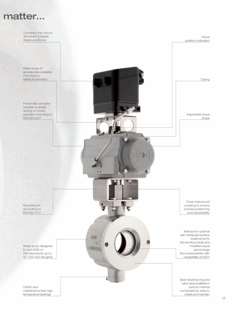
17
Compact top mountSchubert & Salzer digital positioner
Visual position indication
Wide range ofaccessories available,mounting toNAMUR standard Tubing
Pneumatic actuator (double or single acting) or motor actuator mounting toDIN/ISO 5211
Adjustable travel stops
Mounting kit according to DIN/ISO 5211
Close tolerancedcoupling to ensureprecise positioning
and repeatability
Wafer body designed to suit ANSI or DIN standards up to 10” (DN 300 flanged)
Ball sector optional with hardened surface
treatments for demanding media and
modified equal percentage
flow characteristic with rangeability of 300:1
Centric andmaintenance-free, high temperature bearings
Seat retaining ring and valve seat available in
various materialcombinations; easy to
install and maintain
Details that matter...
18
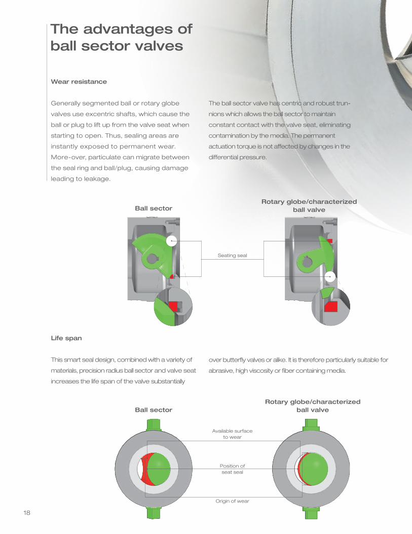
Wear resistance
Generally segmented ball or rotary globe
valves use excentric shafts, which cause the
ball or plug to lift up from the valve seat when
starting to open. Thus, sealing areas are
instantly exposed to permanent wear.
More-over, particulate can migrate between
the seal ring and ball/plug, causing damage
leading to leakage.
The ball sector valve has centric and robust trun-
nions which allows the ball sector to maintain
constant contact with the valve seat, eliminating
contamination by the media. The permanent
actuation torque is not affected by changes in the
differential pressure.
Life span
This smart seal design, combined with a variety of
materials, precision radius ball sector and valve seat
increases the life span of the valve substantially
over butterfly valves or alike. It is therefore particularly suitable for
abrasive, high viscosity or fiber containing media.
Rotary globe/characterized ball valve
Available surface to wear
Position ofseat seal
Origin of wear
Ball sector
Seating seal
Rotary globe/characterized ball valveBall sector
The advantages ofball sector valves
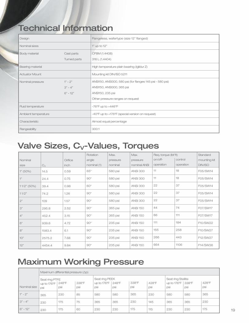
Nominal
size
1” (50%)
1”
1 1/2” (50%)
1 1/2”
2”
3”
4”
6”
8”
10”
12”
CV
14.5
24.4
39.4
74.2
109
295.8
452.4
939.6
1583.4
2575.2
4454.4
Rotation
angle
nominal (1)
65°
90°
60°
90°
90°
90°
90°
90°
90°
90°
90°
Max.
pressure
nominal
580 psi
580 psi
580 psi
580 psi
580 psi
365 psi
365 psi
235 psi
235 psi
235 psi
235 psi
Standard
mounting kit
DIN/ISO
F05/SW14
F05/SW14
F05/SW14
F05/SW14
F05/SW14
F07/SW17
F07/SW17
F10/SW22
F10/SW27
F12/SW27
F14/SW36
Orifice
inch
0.59
0.75
0.98
1.26
1.57
2.52
3.15
4.72
6.1
7.68
9.84
Max.
pressure
nominal ANSI
ANSI 300
ANSI 300
ANSI 300
ANSI 300
ANSI 300
ANSI 150
ANSI 150
ANSI 150
ANSI 150
ANSI 150
ANSI 150
control
operation
18
18
37
37
37
74
111
184
258
443
1106
Valve Sizes, CV-Values, Torqueson/off-
operation
11
11
22
22
22
44
66
111
155
266
664
Req. torque (lbf ft)
Maximum Working Pressure
Nominal size
1” - 2”
3” - 4”
6” - 12”
Maximum differential pressure (∆p)
Seat ring PTFE up to 176°F psi
365
230
230
248°F psi
230
175
175
338°F psi
85
75
60
Seat ring PEEK up to 176°F psi
580
365
230
248°F psi
580
365
230
338°F psi
365
230
175
428°F psi
230
145
115
Seat ring Stellite up to 176°F psi
580
365
230
338°F psi
580
365
230
428°F psi
365
230
175
Design
Nominal sizes
Body material Cast parts
Turned parts
Bearing material
Actuator Mount
Nominal pressure 1” - 2”
3” - 4”
6” - 12”
Fluid temperature
Ambient temperature
Characteristic
Rangeability
Flangeless, wafertype (size 12” flanged)
1” up to 12”
CF8M (1.4408)
316 L (1.4404)
High temperature plain bearing (Iglidur Z)
Mounting kit DIN/ISO 5211
ANSI150, ANSI300, 580 psi (for flanges 145 psi - 580 psi)
ANSI150, ANSI300, 365 psi
ANSI150, 235 psi
Other pressure ranges on request
-76°F up to +446°F
-40°F up to +176°F (special version on request)
Almost equal percentage
300:1
Technical Information
19
Nominal
size
1” (50%)
1”
1 1/2” (50%)
1 1/2”
2”
3”
4”
6”
8”
10”
12”
CV
14.5
24.4
39.4
74.2
109
295.8
452.4
939.6
1583.4
2575.2
4454.4
Rotation
angle
nominal (1)
65°
90°
60°
90°
90°
90°
90°
90°
90°
90°
90°
Max.
pressure
nominal
580 psi
580 psi
580 psi
580 psi
580 psi
365 psi
365 psi
235 psi
235 psi
235 psi
235 psi
Standard
mounting kit
DIN/ISO
F05/SW14
F05/SW14
F05/SW14
F05/SW14
F05/SW14
F07/SW17
F07/SW17
F10/SW22
F10/SW27
F12/SW27
F14/SW36
Orifice
inch
0.59
0.75
0.98
1.26
1.57
2.52
3.15
4.72
6.1
7.68
9.84
Max.
pressure
nominal ANSI
ANSI 300
ANSI 300
ANSI 300
ANSI 300
ANSI 300
ANSI 150
ANSI 150
ANSI 150
ANSI 150
ANSI 150
ANSI 150
control
operation
18
18
37
37
37
74
111
184
258
443
1106
Valve Sizes, CV-Values, Torqueson/off-
operation
11
11
22
22
22
44
66
111
155
266
664
Req. torque (lbf ft)
Maximum Working Pressure
Nominal size
1” - 2”
3” - 4”
6” - 12”
Maximum differential pressure (∆p)
Seat ring PTFE up to 176°F psi
365
230
230
248°F psi
230
175
175
338°F psi
85
75
60
Seat ring PEEK up to 176°F psi
580
365
230
248°F psi
580
365
230
338°F psi
365
230
175
428°F psi
230
145
115
Seat ring Stellite up to 176°F psi
580
365
230
338°F psi
580
365
230
428°F psi
365
230
175
Design
Nominal sizes
Body material Cast parts
Turned parts
Bearing material
Actuator Mount
Nominal pressure 1” - 2”
3” - 4”
6” - 12”
Fluid temperature
Ambient temperature
Characteristic
Rangeability
Flangeless, wafertype (size 12” flanged)
1” up to 12”
CF8M (1.4408)
316 L (1.4404)
High temperature plain bearing (Iglidur Z)
Mounting kit DIN/ISO 5211
ANSI150, ANSI300, 580 psi (for flanges 145 psi - 580 psi)
ANSI150, ANSI300, 365 psi
ANSI150, 235 psi
Other pressure ranges on request
-76°F up to +446°F
-40°F up to +176°F (special version on request)
Almost equal percentage
300:1
Technical Information
20
Tem
pera
ture
Se
at
Tig
htn
ess
Abrasiveness
PTFE
PE
EK
Ste
llite
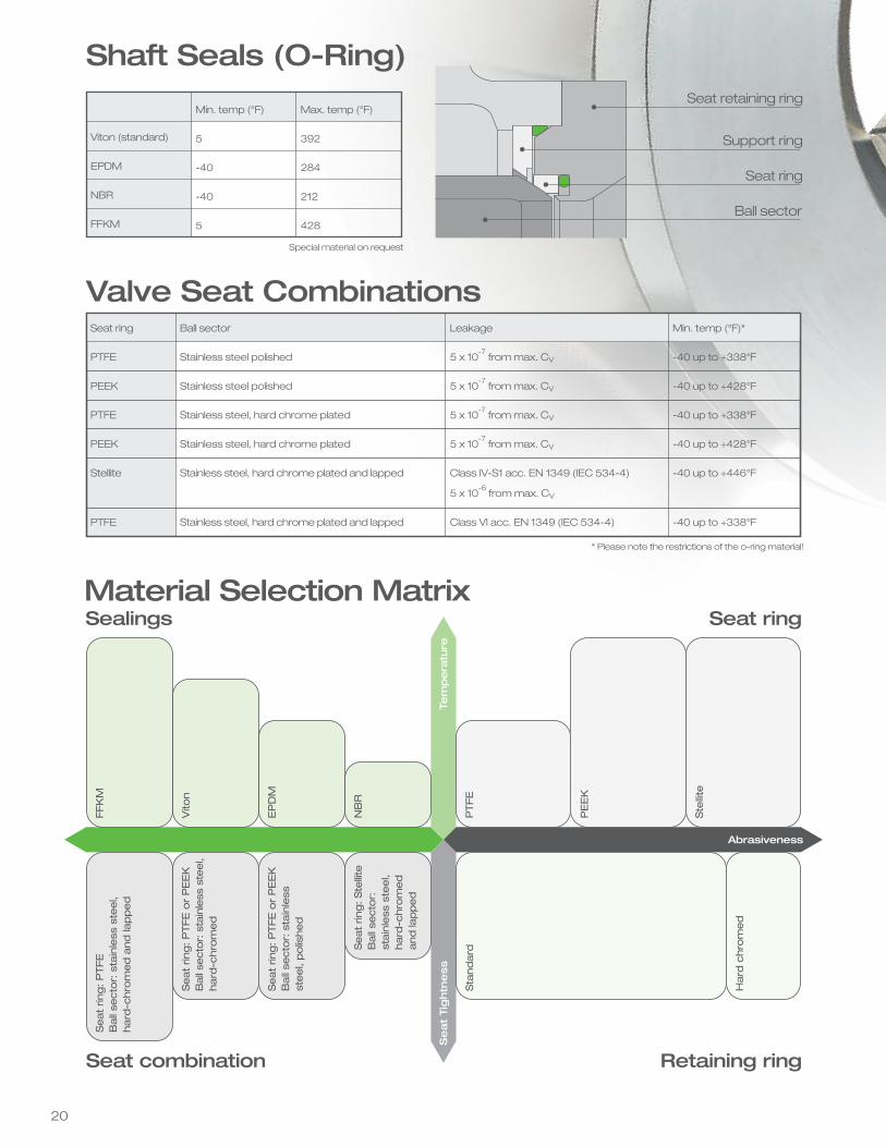
Seat retaining ring
Support ring
Seat ring
Ball sector
Viton (standard)
EPDM
NBR
FFKM
Min. temp (°F)
5
-40
-40
5
Max. temp (°F)
392
284
212
428
Valve Seat CombinationsSeat ring
PTFE
PEEK
PTFE
PEEK
Stellite
PTFE
Ball sector
Stainless steel polished
Stainless steel polished
Stainless steel, hard chrome plated
Stainless steel, hard chrome plated
Stainless steel, hard chrome plated and lapped
Stainless steel, hard chrome plated and lapped
Leakage
5 x 10⁻⁷
from max. CV
5 x 10⁻⁷
from max. CV
5 x 10⁻⁷
from max. CV
5 x 10⁻⁷
from max. CV
Class IV-S1 acc. EN 1349 (IEC 534-4)
5 x 10⁻⁶
from max. CV
Class VI acc. EN 1349 (IEC 534-4)
Min. temp (°F)*
-40 up to +338°F
-40 up to +428°F
-40 up to +338°F
-40 up to +428°F
-40 up to +446°F
-40 up to +338°F
* Please note the restrictions of the o-ring material!
Sealings Seat ring
FFK
M
Vito
n
EP
DM
NB
R
Seat rin
g: P
TFE
Ball
secto
r: s
tain
less
ste
el,
hard
-chro
med a
nd la
pped
Seat rin
g: P
TFE
or
PE
EK
Ball
secto
r: s
tain
less
ste
el,
hard
-chro
med
Seat rin
g: P
TFE
or
PE
EK
Ball
secto
r: s
tain
less
st
eel,
polis
hed
Seat rin
g: Ste
llite
Ball
secto
r:
stain
less
ste
el,
hard
-chro
med
and la
pped
Seat combination Retaining ring
Sta
ndard
Hard
chro
med
Material Selection Matrix
Special material on request
Shaft Seals (O-Ring)
21
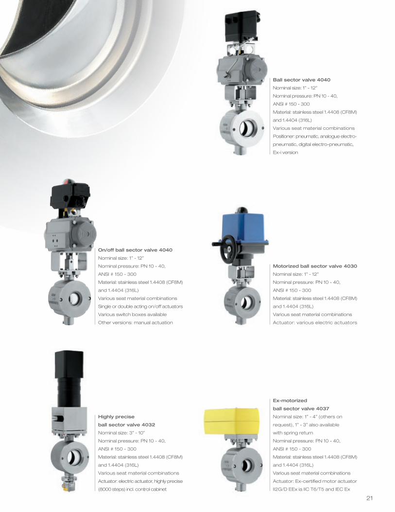
Ball sector valve 4040
Nominal size: 1” - 12”
Nominal pressure: PN 10 - 40,
ANSI # 150 - 300
Material: stainless steel 1.4408 (CF8M)
and 1.4404 (316L)
Various seat material combinations
Positioner: pneumatic, analogue electro-
pneumatic, digital electro-pneumatic,
Ex-i version
Motorized ball sector valve 4030
Nominal size: 1” - 12”
Nominal pressure: PN 10 - 40,
ANSI # 150 - 300
Material: stainless steel 1.4408 (CF8M)
and 1.4404 (316L)
Various seat material combinations
Actuator: various electric actuators
Ex-motorized
ball sector valve 4037
Nominal size: 1” - 4” (others on
request), 1” - 3” also available
with spring return
Nominal pressure: PN 10 - 40,
ANSI # 150 - 300
Material: stainless steel 1.4408 (CF8M)
and 1.4404 (316L)
Various seat material combinations
Actuator: Ex-certified motor actuator
II2G/D EEx ia IIC T6/T5 and IEC Ex
On/off ball sector valve 4040
Nominal size: 1” - 12”
Nominal pressure: PN 10 - 40,
ANSI # 150 - 300
Material: stainless steel 1.4408 (CF8M)
and 1.4404 (316L)
Various seat material combinations
Single or double acting on/off actuators
Various switch boxes available
Other versions: manual actuation
Highly precise
ball sector valve 4032
Nominal size: 3” - 10”
Nominal pressure: PN 10 - 40,
ANSI # 150 - 300
Material: stainless steel 1.4408 (CF8M)
and 1.4404 (316L)
Various seat material combinations
Actuator: electric actuator, highly precise
(8000 steps) incl. control cabinet
Tem
pera
ture
Se
at
Tig
htn
ess
Abrasiveness
PTFE
PE
EK
Ste
llite
Seat retaining ring
Support ring
Seat ring
Ball sector
Viton (standard)
EPDM
NBR
FFKM
Min. temp (°F)
5
-40
-40
5
Max. temp (°F)
392
284
212
428
Valve Seat CombinationsSeat ring
PTFE
PEEK
PTFE
PEEK
Stellite
PTFE
Ball sector
Stainless steel polished
Stainless steel polished
Stainless steel, hard chrome plated
Stainless steel, hard chrome plated
Stainless steel, hard chrome plated and lapped
Stainless steel, hard chrome plated and lapped
Leakage
5 x 10⁻⁷
from max. CV
5 x 10⁻⁷
from max. CV
5 x 10⁻⁷
from max. CV
5 x 10⁻⁷
from max. CV
Class IV-S1 acc. EN 1349 (IEC 534-4)
5 x 10⁻⁶
from max. CV
Class VI acc. EN 1349 (IEC 534-4)
Min. temp (°F)*
-40 up to +338°F
-40 up to +428°F
-40 up to +338°F
-40 up to +428°F
-40 up to +446°F
-40 up to +338°F
* Please note the restrictions of the o-ring material!
Sealings Seat ring
FFK
M
Vito
n
EP
DM
NB
R
Seat rin
g: P
TFE
Ball
secto
r: s
tain
less
ste
el,
hard
-chro
med a
nd la
pped
Seat rin
g: P
TFE
or
PE
EK
Ball
secto
r: s
tain
less
ste
el,
hard
-chro
med
Seat rin
g: P
TFE
or
PE
EK
Ball
secto
r: s
tain
less
st
eel,
polis
hed
Seat rin
g: Ste
llite
Ball
secto
r:
stain
less
ste
el,
hard
-chro
med
and la
pped
Seat combination Retaining ring
Sta
ndard
Hard
chro
med
Material Selection Matrix
Special material on request
Shaft Seals (O-Ring)
22
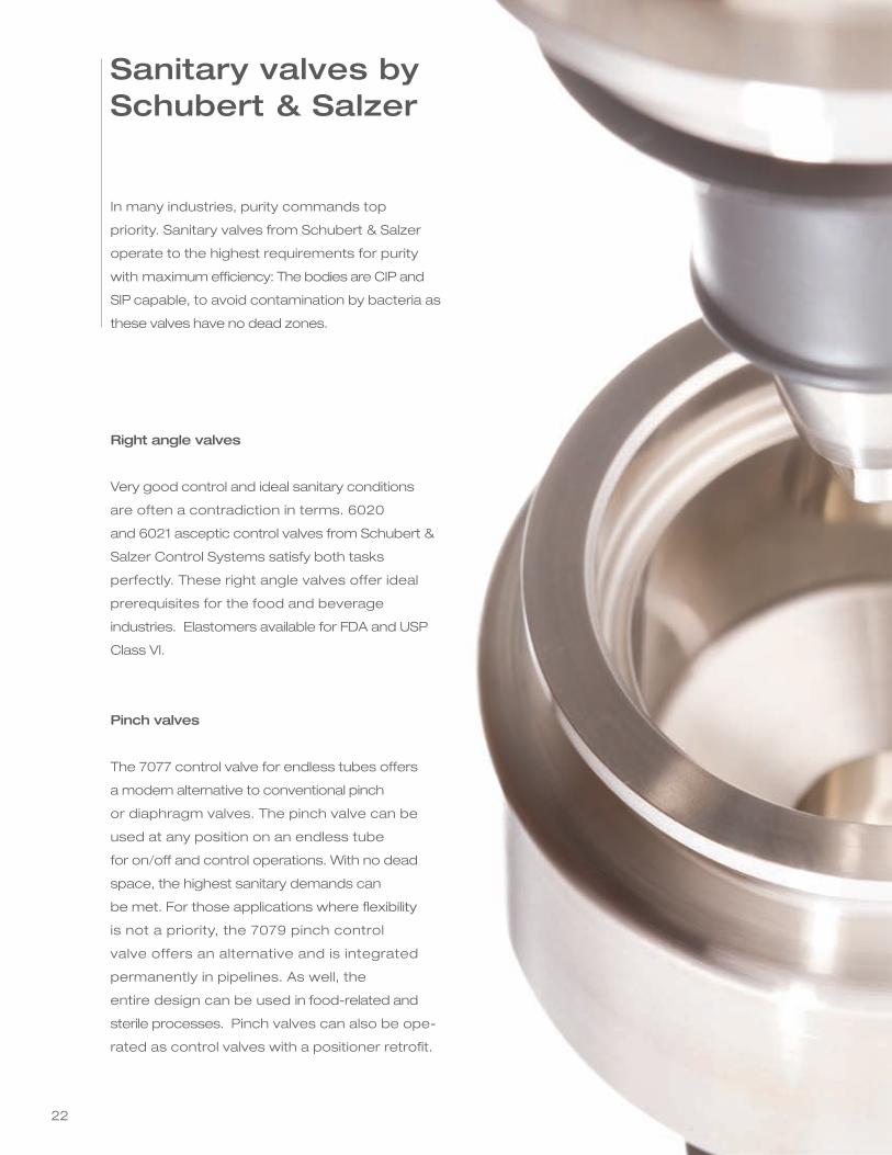
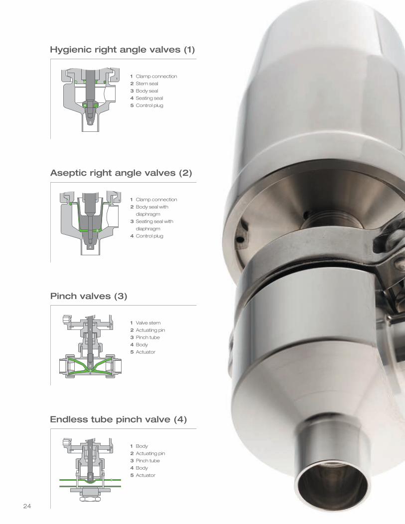
In many industries, purity commands top
priority. Sanitary valves from Schubert & Salzer
operate to the highest requirements for purity
with maximum efficiency: The bodies are CIP and
SIP capable, to avoid contamination by bacteria as
these valves have no dead zones.
Right angle valves
Very good control and ideal sanitary conditions
are often a contradiction in terms. 6020
and 6021 asceptic control valves from Schubert &
Salzer Control Systems satisfy both tasks
perfectly. These right angle valves offer ideal
prerequisites for the food and beverage
industries. Elastomers available for FDA and USP
Class VI.
Pinch valves
The 7077 control valve for endless tubes offers
a modern alternative to conventional pinch
or diaphragm valves. The pinch valve can be
used at any position on an endless tube
for on/off and control operations. With no dead
space, the highest sanitary demands can
be met. For those applications where flexibility
is not a priority, the 7079 pinch control
valve offers an alternative and is integrated
permanently in pipelines. As well, the
entire design can be used in food-related and
sterile processes. Pinch valves can also be ope-
rated as control valves with a positioner retrofit.
Sanitary valves bySchubert & Salzer
23
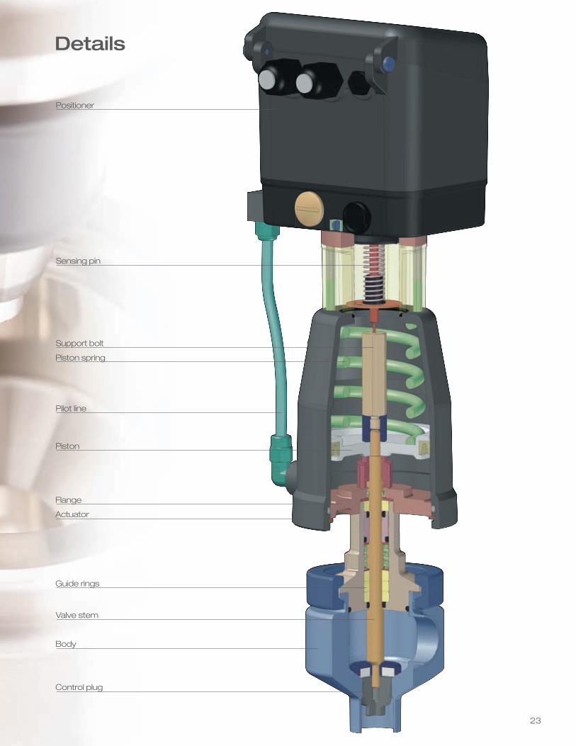
Positioner
Sensing pin
Support bolt
Piston spring
Pilot line
Piston
Actuator
Guide rings
Valve stem
Body
Control plug
Flange
Details
24
3
Hygienic right angle valves (1)
1 Clamp connection
2 Stem seal
3 Body seal
4 Seating seal
5 Control plug
231
5
4
Aseptic right angle valves (2)
1 Clamp connection
2 Body seal with
diaphragm
3 Seating seal with
diaphragm
4 Control plug
Pinch valves (3)
1 Valve stem
2 Actuating pin
3 Pinch tube
4 Body
5 Actuator
Endless tube pinch valve (4)
1 Body
2 Actuating pin
3 Pinch tube
4 Body
5 Actuator
1
3
4
1
5
2
1
2
5
4
2
34
3
25
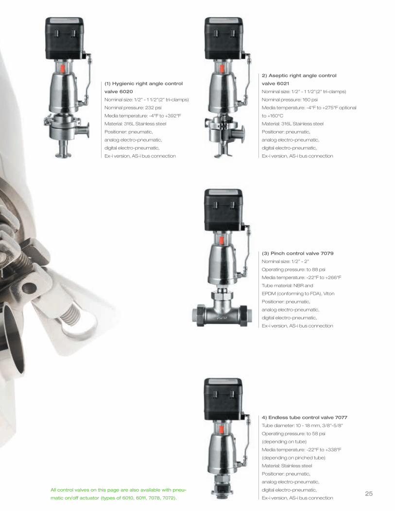
2) Aseptic right angle control
valve 6021
Nominal size: 1/2” - 1 1/2”(2” tri-clamps)
Nominal pressure: 160 psi
Media temperature: -4°F to +275°F optional
to +160°C
Material: 316L Stainless steel
Positioner: pneumatic,
analog electro-pneumatic,
digital electro-pneumatic,
Ex-i version, AS-i bus connection
(3) Pinch control valve 7079
Nominal size: 1/2” - 2”
Operating pressure: to 88 psi
Media temperature: -22°F to +266°F
Tube material: NBR and
EPDM (conforming to FDA), Viton
Positioner: pneumatic,
analog electro-pneumatic,
digital electro-pneumatic,
Ex-i version, AS-i bus connection
4) Endless tube control valve 7077
Tube diameter: 10 - 18 mm, 3/8”-5/8”
Operating pressure: to 58 psi
(depending on tube)
Media temperature: -22°F to +338°F
(depending on pinched tube)
Material: Stainless steel
Positioner: pneumatic,
analog electro-pneumatic,
digital electro-pneumatic,
Ex-i version, AS-i bus connection
(1) Hygienic right angle control
valve 6020
Nominal size: 1/2” - 1 1/2”(2” tri-clamps)
Nominal pressure: 232 psi
Media temperature: -4°F to +392°F
Material: 316L Stainless steel
Positioner: pneumatic,
analog electro-pneumatic,
digital electro-pneumatic,
Ex-i version, AS-i bus connection
All control valves on this page are also available with pneu-
matic on/off actuator (types of 6010, 6011, 7078, 7072).
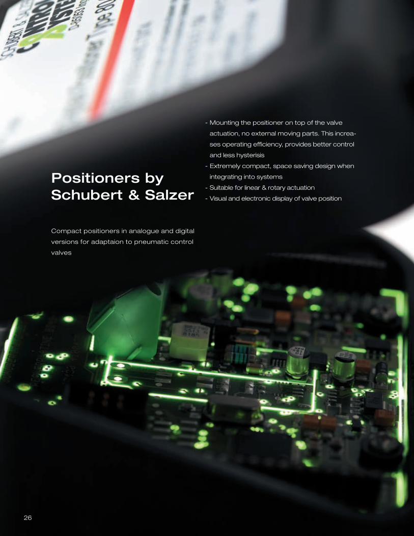
Compact positioners in analogue and digital
versions for adaptaion to pneumatic control
valves
Positioners bySchubert & Salzer
Mounting the positioner on top of the valve
actuation, no external moving parts. This increa-
ses operating efficiency, provides better control
and less hysterisis
Extremely compact, space saving design when
integrating into systems
Suitable for linear & rotary actuation
Visual and electronic display of valve position
-
-
-
-
26
27
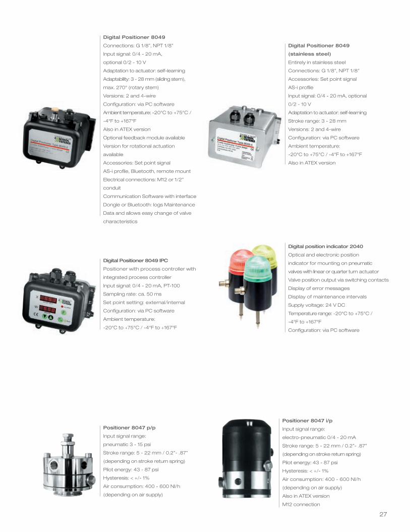
Digital Positioner 8049
Connections: G 1/8”, NPT 1/8”
Input signal: 0/4 - 20 mA,
optional 0/2 - 10 V
Adaptation to actuator: self-learning
Adaptability: 3 - 28 mm (sliding stem),
max. 270° (rotary stem)
Versions: 2 and 4-wire
Configuration: via PC software
Ambient temperature: -20°C to +75°C /
-4°F to +167°F
Also in ATEX version
Optional feedback module available
Version for rotational actuation
available
Accessories: Set point signal
AS-i profile, Bluetooth, remote mount
Electrical connections: M12 or 1/2”
conduit
Communication Software with interface
Dongle or Bluetooth: logs Maintenance
Data and allows easy change of valve
characteristics
Digital Positioner 8049 IPC
Positioner with process controller with
integrated process controller
Input signal: 0/4 - 20 mA, PT-100
Sampling rate: ca. 50 ms
Set point setting: external/internal
Configuration: via PC software
Ambient temperature:
-20°C to +75°C / -4°F to +167°F
Positioner 8047 p/p
Input signal range:
pneumatic 3 - 15 psi
Stroke range: 5 - 22 mm / 0.2”- .87”
(depending on stroke return spring)
Pilot energy: 43 - 87 psi
Hysteresis: < +/- 1%
Air consumption: 400 - 600 Nl/h
(depending on air supply)
Digital Positioner 8049
(stainless steel)
Entirely in stainless steel
Connections: G 1/8”, NPT 1/8”
Accessories: Set point signal
AS-i profile
Input signal: 0/4 - 20 mA, optional
0/2 - 10 V
Adaptation to actuator: self-learning
Stroke range: 3 - 28 mm
Versions: 2 and 4-wire
Configuration: via PC software
Ambient temperature:
-20°C to +75°C / -4°F to +167°F
Also in ATEX version
Positioner 8047 i/p
Input signal range:
electro-pneumatic 0/4 - 20 mA
Stroke range: 5 - 22 mm / 0.2”- .87”
(depending on stroke return spring)
Pilot energy: 43 - 87 psi
Hysteresis: < +/- 1%
Air consumption: 400 - 600 Nl/h
(depending on air supply)
Also in ATEX version
M12 connection
Digital position indicator 2040
Optical and electronic position
indicator for mounting on pneumatic
valves with linear or quarter turn actuator
Valve position output via switching contacts
Display of error messages
Display of maintenance intervals
Supply voltage: 24 V DC
Temperature range: -20°C to +75°C /
-4°F to +167°F
Configuration: via PC software
28
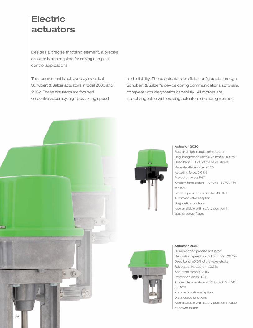
Besides a precise throttling element, a precise
actuator is also required for solving complex
control applications.
This requirement is achieved by electrical
Schubert & Salzer actuators, model 2030 and
2032. These actuators are focused
on control accuracy, high positioning speed
and reliability. These actuators are field configurable through
Schubert & Salzer‘s device config communications software,
complete with diagnostics capabilitiy. All motors are
interchangeable with existing actuators (including Belimo).
Electric actuators
Actuator 2030
Fast and high-resolution actuator
Regulating speed up to 0.75 mm/s (.03 ”/s)
Dead band: ±0.2% of the valve stroke
Repeatability: approx. ±0.1%
Actuating force: 2.0 kN
Protection class: IP67
Ambient temperature: -10 °C to +60 °C / 14°F
to 140°F
Low temperature version to -40° C/ F
Automatic valve adaption
Diagnostics functions
Also available with safety position in
case of power failure
Actuator 2032
Compact and precise actuator
Regulating speed up to 1.5 mm/s (.06 ”/s)
Dead band: ±0.6% of the valve stroke
Repeatability: approx. ±0.3%
Actuating force: 0.8 kN
Protection class: IP65
Ambient temperature: -10 °C to +60 °C / 14°F
to 140°F
Automatic valve adaption
Diagnostics functions
Also available with safety position in case
of power failure
2929
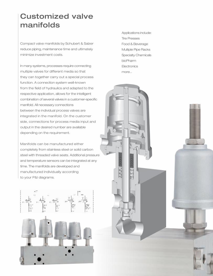
Customized valve manifolds
Compact valve manifolds by Schubert & Salzer
reduce piping, maintenance time and ultimately
minimize investment costs.
In many systems, processes require connecting
multiple valves for different media so that
they can together carry out a special process
function. A connection system well-known
from the field of hydraulics and adapted to the
respective application, allows for the intelligent
combination of several valves in a customer-specific
manifold. All necessary connections
between the individual process valves are
integrated in the manifold. On the customer
side, connections for process media input and
output in the desired number are available
depending on the requirement.
Manifolds can be manufactured either
completely from stainless steel or solid carbon
steel with threaded valve seats. Additional pressure
and temperature sensors can be integrated at any
time. The manifolds are developed and
manufactured individually according
to your P&I diagrams.
Applications include:
Tire Presses
Food & Beverage
Multiple Pipe Racks
Specialty Chemicals
bioPharm
Electronics
more...
30
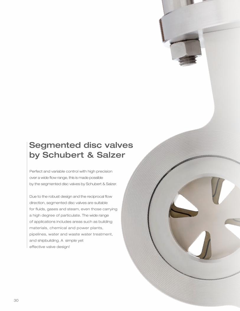
Perfect and variable control with high precision
over a wide flow range, this is made possible
by the segmented disc valves by Schubert & Salzer.
Due to the robust design and the reciprocal flow
direction, segmented disc valves are suitable
for fluids, gases and steam, even those carrying
a high degree of particulate. The wide range
of applications includes areas such as building
materials, chemical and power plants,
pipelines, water and waste water treatment,
and shipbuilding. A simple yet
effective valve design!
Segmented disc valves by Schubert & Salzer
31
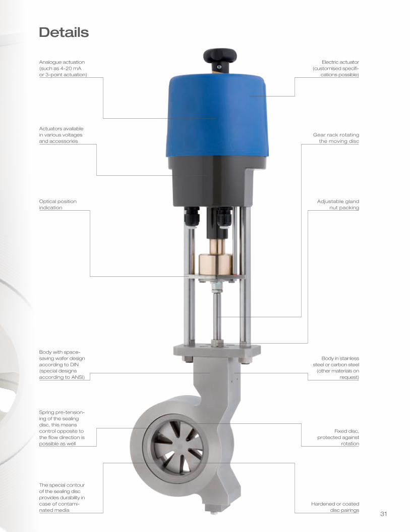
Details
Analogue actuation (such as 4-20 mA or 3-point actuation)
Electric actuator (customised specifi-
cations possible)
Actuators available in various voltages and accessories
Gear rack rotating the moving disc
Optical position indication
Adjustable gland nut packing
Body with space-saving wafer design according to DIN (special designs according to ANSI)
Body in stainless steel or carbon steel
(other materials on request)
Spring pre-tension-ing of the sealing disc, this means control opposite to the flow direction is possible as well
Fixed disc, protected against
rotation
The special contour of the sealing disc provides durability in case of contami-nated media
Hardened or coated disc pairings
32
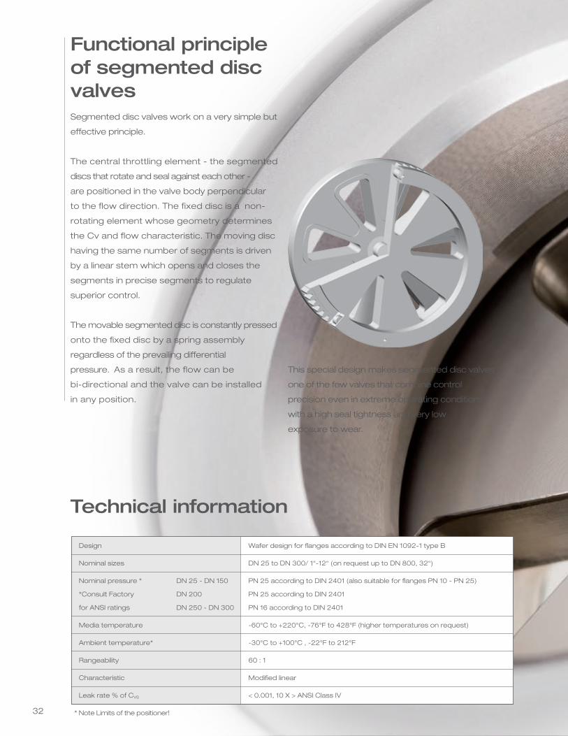
Segmented disc valves work on a very simple but
effective principle.
The central throttling element - the segmented
discs that rotate and seal against each other -
are positioned in the valve body perpendicular
to the flow direction. The fixed disc is a non-
rotating element whose geometry determines
the Cv and flow characteristic. The moving disc
having the same number of segments is driven
by a linear stem which opens and closes the
segments in precise segments to regulate
superior control.
The movable segmented disc is constantly pressed
onto the fixed disc by a spring assembly
regardless of the prevailing differential
pressure. As a result, the flow can be
bi-directional and the valve can be installed
in any position.
Functional principle of segmented disc valves
Technical information
* Note Limits of the positioner!
Wafer design for flanges according to DIN EN 1092-1 type B
DN 25 to DN 300/ 1“-12“ (on request up to DN 800, 32“)
PN 25 according to DIN 2401 (also suitable for flanges PN 10 - PN 25)
PN 25 according to DIN 2401
PN 16 according to DIN 2401
-60°C to +220°C, -76°F to 428°F (higher temperatures on request)
-30°C to +100°C , -22°F to 212°F
60 : 1
Modified linear
< 0.001, 10 X > ANSI Class IV
This special design makes segmented disc valves
one of the few valves that combine control
precision even in extreme operating conditions
with a high seal tightness and very low
exposure to wear.
Design
Nominal sizes
Nominal pressure * DN 25 - DN 150
*Consult Factory DN 200
for ANSI ratings DN 250 - DN 300
Media temperature
Ambient temperature*
Rangeability
Characteristic
Leak rate % of CVS
33
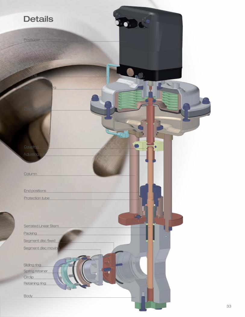
Positioner
Pilot line
Coupling
Column
End positions
Serrated Linear Stem
Adjusting nut
Protection tube
Packing
Segment disc moving
Segment disc fixed
Diaphragm housing
Diaphragm plate
Sliding ring
Spring retainer
Body
Circlip
Retaining ring
Details
34
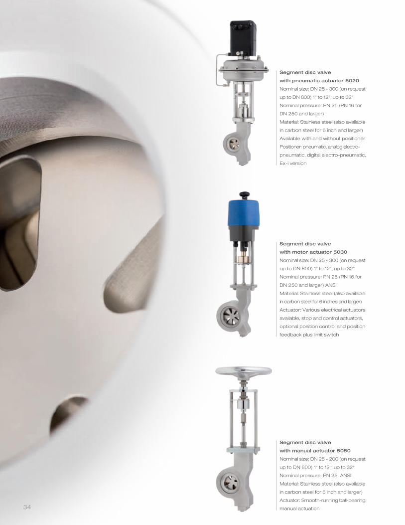
Segment disc valve
with pneumatic actuator 5020
Nominal size: DN 25 - 300 (on request
up to DN 800) 1“ to 12“, up to 32“
Nominal pressure: PN 25 (PN 16 for
DN 250 and larger)
Material: Stainless steel (also available
in carbon steel for 6 inch and larger)
Available with and without positioner
Positioner: pneumatic, analog electro-
pneumatic, digital electro-pneumatic,
Ex-i version
Segment disc valve
with motor actuator 5030
Nominal size: DN 25 - 300 (on request
up to DN 800) 1” to 12”, up to 32”
Nominal pressure: PN 25 (PN 16 for
DN 250 and larger) ANSI
Material: Stainless steel (also available
in carbon steel for 6 inches and larger)
Actuator: Various electrical actuators
available, stop and control actuators,
optional position control and position
feedback plus limit switch
Segment disc valve
with manual actuator 5050
Nominal size: DN 25 - 200 (on request
up to DN 800) 1“ to 12“, up to 32“
Nominal pressure: PN 25, ANSI
Material: Stainless steel (also available
in carbon steel for 6 inch and larger)
Actuator: Smooth-running ball-bearing
manual actuation
35
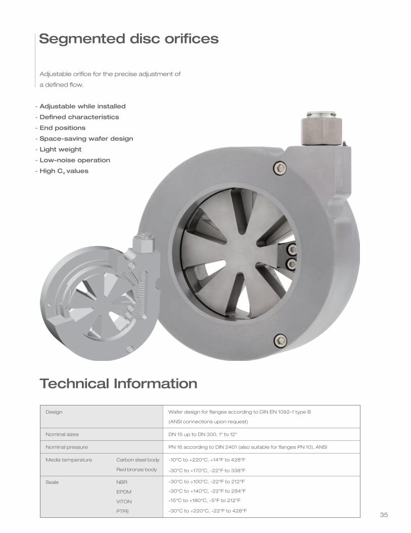
Adjustable orifice for the precise adjustment of
a defined flow.
Adjustable while installed
Defined characteristics
End positions
Space-saving wafer design
Light weight
Low-noise operation
High CV values
Segmented disc orifices
-
-
-
-
-
-
-
Technical Information
Design
Nominal sizes
Nominal pressure
Media temperature Carbon steel body
Red bronze body
Seals NBR
EPDM
VITON
PTFE
Wafer design for flanges according to DIN EN 1092-1 type B
(ANSI connections upon request)
DN 15 up to DN 300, 1“ to 12“
PN 16 according to DIN 2401 (also suitable for flanges PN 10), ANSI
-10°C to +220°C, +14°F to 428°F
-30°C to +170°C, -22°F to 338°F
-30°C to +100°C, -22°F to 212°F
-30°C to +140°C, -22°F to 284°F
-15°C to +180°C, -5°F to 212°F
-30°C to +220°C, -22°F to 428°F
www.schubertsalzerinc.com
Schubert & Salzer Inc.4601 Corporate Drive NWSuite 100Concord, N.C. 28027
Tel: +1 (704) 789 - 0169Fax: +1 (704) 792 - 9783Toll Free U.S. & Canada(877) 414-9664
info@schubertsalzerinc.comwww.schubertsalzerinc.comwww.schubert-salzer.com