Embed Size (px)
Citation preview
April 2016
Product Overview
Rotary EncodersFor Potentially Explosive Atmospheres (ATEX)
2 Product Overview: Rotary Encoders for Potentially Explosive Atmospheres (ATEX) 4/2016
Rotary encoders for use in potentially explosive areas
Introduction
There are many types of applications in industry where exposure to potentially explosive atmospheres is virtually unavoidable, for example on paint spray lines, printing machines or silage systems.
The condition of equipment and facilities operated in potentially explosive atmospheres is defi ned by ATEX Directive 2014/34/EU, also known as ATEX 95 (ATEX derives its name from the French “atmosphères explosibles,” which means explosive atmospheres).
This directive has been in effect since February 26, 2014 and has replaced all other existing regulations, which cover the same subjects, within the entire European Union (EU). In the fi eld of explosion protection, national regulations must not contain any diverging requirements and/or any require-ments beyond the scope of this directive. Products that are placed on the market or put into service after February 26, 2014 must meet the requirements of the directive.
Standard
CENELEC (European Committee for Electrotechnical Standardization) prepared the EU standard EN 60 079 for explosion protection on the basis of the EU directive.
Usability (classifi cation into zones and
categories)
In potentially explosive areas, the operating conditions must be considered carefully. The installer/operator must therefore assess the explosion risk of production facilities and divide them into zones that refl ect the degree of danger based on• the probability and duration of the
occurrence of dangerous potentially explosive atmospheres,
• the probability of the presence, activation and effectiveness of sources of ignition, as well as
• the scope of the expected effects of explosions.
Operating equipment for potentially explosive areas is classifi ed into three
categories (for Equipment Group II for electrical equipment except mines liable to be endangered by fi redamp), depending on its design.• Category 1 ensures a very high level of
safety• Category 2 ensures a high level of safety• Category 3 ensures a normal level of
safety
Classifi cation into zones
The composition of the atmosphere is decisive for the classifi cation into zones:• Potentially explosive atmosphere
consisting of a mixture of air and gases, vapors or mists
– Zone 0: Continuously, for long periods, frequently, majority of the time
– Zone 1: Occasionally in normal operation
– Zone 2: Rare, for a short period• Potentially explosive atmosphere that
consists of a mixture of air and dust – Zone 20: Continuously, for long
periods, frequently, majority of the time – Zone 21: Occasionally in normal
operation – Zone 22: Rare, for a short period
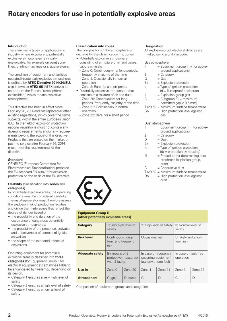
Equipment Group II
(other potentially explosive areas)
Category 1: Very high level of safety
2: High level of safety 3: Normal level of safety
Risk level Continuous, long-term and frequent risk
Occasional risk Unlikely and short-term risk
Adequate safety By means of 2 protective measures/with 2 faults
In case of frequently occurring equipment faults/with one fault
In case of fault-free operation
Use in Zone 0 Zone 20 Zone 1 Zone 21 Zone 2 Zone 22
Atmosphere G (gas) D (dust) G D G D
Comparison of equipment groups and categories
Designation
All explosion-proof electrical devices are marked using a uniform code.
Gas atmosphereII = Equipment group (II = for above-
ground applications)2 = CategoryG = GasEx = Explosion protectiond = Type of ignition protection
(d = fl ameproof enclosure)II = Explosion group gasC = Subgroup (C = maximum
permitted gap < 0.5 mm)T120 °C = Maximum surface temperatureGb = High protection level against
gas
Dust atmosphereII = Equipment group (II = for above-
ground applications)2 = CategoryD = DustEx = Explosion protectiontb = Type of ignition protection
(tb = protection by housing)III = Procedure for determining dust
proofness (explosion group, dust)
C = Conductive dustT120 °C = Maximum surface temperatureDb = High protection level against
dust
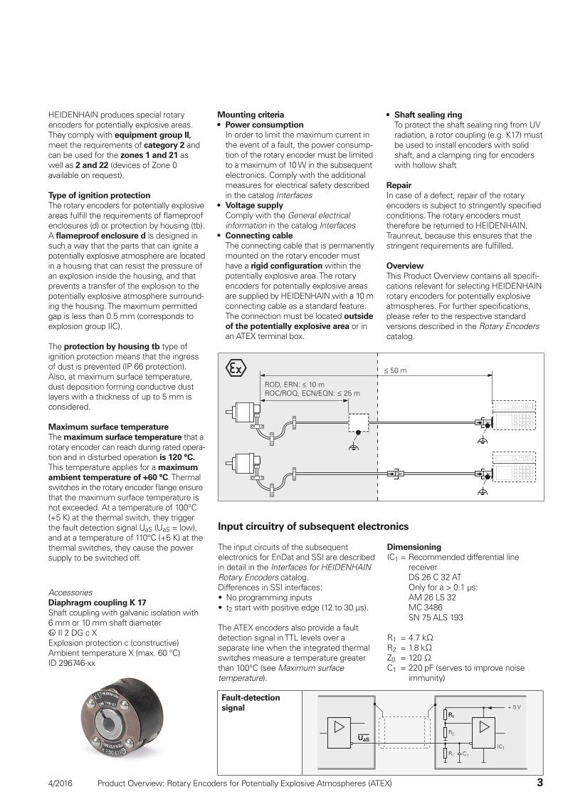
ROD, ERN: 10 mROC/ROQ, ECN/EQN: 25 m
50 m
4/2016 Product Overview: Rotary Encoders for Potentially Explosive Atmospheres (ATEX) 3
HEIDENHAIN produces special rotary encoders for potentially explosive areas. They comply with equipment group II, meet the requirements of category 2 and can be used for the zones 1 and 21 as well as 2 and 22 (devices of Zone 0 available on request).
Type of ignition protection
The rotary encoders for potentially explosive areas fulfi ll the requirements of fl ameproof enclosures (d) or protection by housing (tb). A fl ameproof enclosure d is designed in such a way that the parts that can ignite a potentially explosive atmosphere are located in a housing that can resist the pressure of an explosion inside the housing, and that prevents a transfer of the explosion to the potentially explosive atmosphere surround-ing the housing. The maximum permitted gap is less than 0.5 mm (corresponds to explosion group IIC).
The protection by housing tb type of ignition protection means that the ingress of dust is prevented (IP 66 protection). Also, at maximum surface temperature, dust deposition forming conductive dust layers with a thickness of up to 5 mm is considered.
Maximum surface temperature
The maximum surface temperature that a rotary encoder can reach during rated opera-tion and in disturbed operation is 120 °C. This temperature applies for a maximum
ambient temperature of +60 °C. Thermal switches in the rotary encoder fl ange ensure that the maximum surface temperature is not exceeded. At a temperature of 100°C (+5 K) at the thermal switch, they trigger the fault detection signal UaS (UaS = low), and at a temperature of 110°C (+5 K) at the thermal switches, they cause the power supply to be switched off.
Mounting criteria
• Power consumption
In order to limit the maximum current in the event of a fault, the power consump-tion of the rotary encoder must be limited to a maximum of 10 W in the subsequent electronics. Comply with the additional measures for electrical safety described in the catalog Interfaces
• Voltage supply
Comply with the General electrical information in the catalog Interfaces
• Connecting cable
The connecting cable that is permanently mounted on the rotary encoder must have a rigid confi guration within the potentially explosive area. The rotary encoders for potentially explosive areas are supplied by HEIDENHAIN with a 10 m connecting cable as a standard feature. The connection must be located outside
of the potentially explosive area or in an ATEX terminal box.
Input circuitry of subsequent electronics
The input circuits of the subsequent electronics for EnDat and SSI are described in detail in the Interfaces for HEIDENHAIN Rotary Encoders catalog.Differences in SSI interfaces:• No programming inputs• t2 start with positive edge (12 to 30 µs).
The ATEX encoders also provide a fault detection signal in TTL levels over a separate line when the integrated thermal switches measure a temperature greater than 100°C (see Maximum surface temperature).
Dimensioning
IC1 = Recommended differential line receiver
DS 26 C 32 AT Only for a > 0.1 µs: AM 26 LS 32 MC 3486 SN 75 ALS 193
R1 = 4.7 kR2 = 1.8 kZ0 = 120 C1 = 220 pF (serves to improve noise
immunity)
Fault-detection
signal
AccessoriesDiaphragm coupling K 17
Shaft coupling with galvanic isolation with 6 mm or 10 mm shaft diameter
II 2 DG c XExplosion protection c (constructive)Ambient temperature X (max. 60 °C)ID 296746-xx
• Shaft sealing ring
To protect the shaft sealing ring from UV radiation, a rotor coupling (e.g. K17) must be used to install encoders with solid shaft, and a clamping ring for encoders with hollow shaft
Repair
In case of a defect, repair of the rotary encoders is subject to stringently specifi ed conditions. The rotary encoders must therefore be returned to HEIDENHAIN, Traunreut, because this ensures that the stringent requirements are fulfi lled.
Overview
This Product Overview contains all specifi -cations relevant for selecting HEIDENHAIN rotary encoders for potentially explosive atmospheres. For further specifi cations, please refer to the respective standard versions described in the Rotary Encoders catalog.
4 Product Overview: Rotary Encoders for Potentially Explosive Atmospheres (ATEX) 4/2016
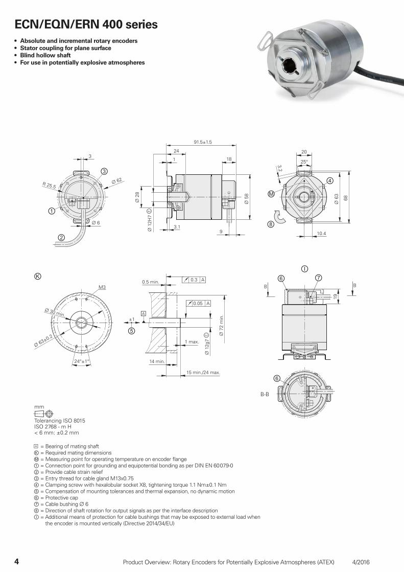
ECN/EQN/ERN 400 series
• Absolute and incremental rotary encoders
• Stator coupling for plane surface
• Blind hollow shaft
• For use in potentially explosive atmospheres
= Bearing of mating shaftⓀ = Required mating dimensionsⓂ = Measuring point for operating temperature on encoder fl ange① = Connection point for grounding and equipotential bonding as per DIN EN 60 079-0 ② = Provide cable strain relief ③ = Entry thread for cable gland M13x0.75④ = Clamping screw with hexalobular socket X8, tightening torque 1.1 Nm±0.1 Nm⑤ = Compensation of mounting tolerances and thermal expansion, no dynamic motion⑥ = Protective cap⑦ = Cable bushing 6⑧ = Direction of shaft rotation for output signals as per the interface descriptionⒾ = Additional means of protection for cable bushings that may be exposed to external load when
the encoder is mounted vertically (Directive 2014/34/EU)
4/2016 Product Overview: Rotary Encoders for Potentially Explosive Atmospheres (ATEX) 5
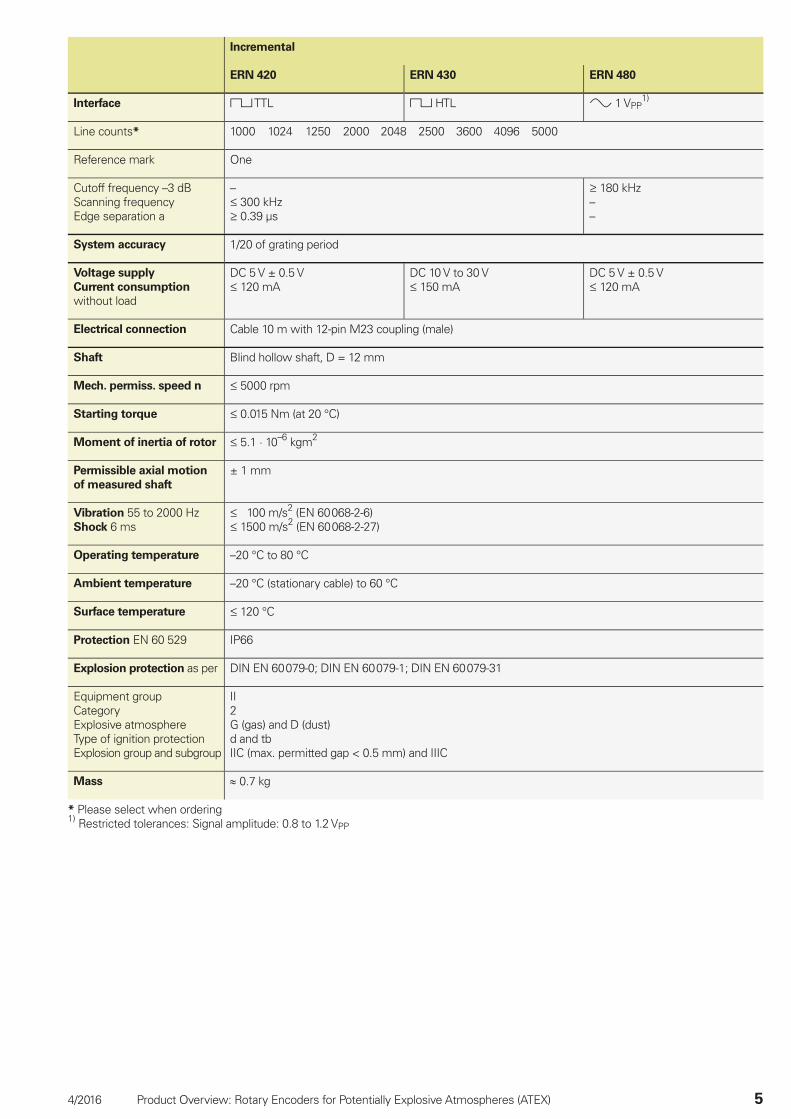
Incremental
ERN 420 ERN 430 ERN 480
Interface TTL HTL 1 VPP1)
Line counts* 1000 1024 1250 2000 2048 2500 3600 4096 5000
Reference mark One
Cutoff frequency –3 dBScanning frequencyEdge separation a
– 300 kHz 0.39 µs
180 kHz––
System accuracy 1/20 of grating period
Voltage supply
Current consumption
without load
DC 5 V ± 0.5 V 120 mA
DC 10 V to 30 V 150 mA
DC 5 V ± 0.5 V 120 mA
Electrical connection Cable 10 m with 12-pin M23 coupling (male)
Shaft Blind hollow shaft, D = 12 mm
Mech. permiss. speed n 5000 rpm
Starting torque 0.015 Nm (at 20 °C)
Moment of inertia of rotor 5.1 · 10–6 kgm2
Permissible axial motion
of measured shaft
± 1 mm
Vibration 55 to 2000 HzShock 6 ms
100 m/s2 (EN 60 068-2-6) 1500 m/s2 (EN 60 068-2-27)
Operating temperature –20 °C to 80 °C
Ambient temperature –20 °C (stationary cable) to 60 °C
Surface temperature 120 °C
Protection EN 60 529 IP66
Explosion protection as per DIN EN 60 079-0; DIN EN 60 079-1; DIN EN 60 079-31
Equipment groupCategoryExplosive atmosphereType of ignition protectionExplosion group and subgroup
II2G (gas) and D (dust)d and tbIIC (max. permitted gap < 0.5 mm) and IIIC
Mass 0.7 kg
* Please select when ordering1) Restricted tolerances: Signal amplitude: 0.8 to 1.2 VPP
6 Product Overview: Rotary Encoders for Potentially Explosive Atmospheres (ATEX) 4/2016
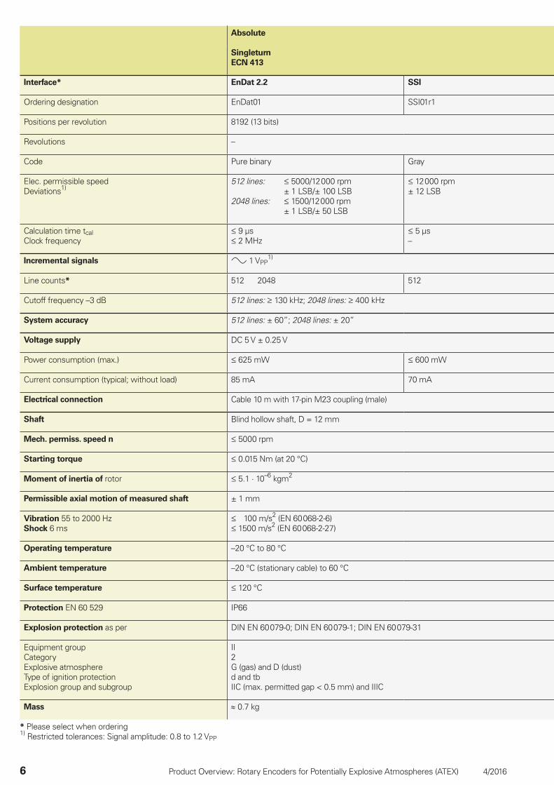
Absolute
Singleturn
ECN 413
Interface* EnDat 2.2 SSI
Ordering designation EnDat01 SSI01r1
Positions per revolution 8192 (13 bits)
Revolutions –
Code Pure binary Gray
Elec. permissible speedDeviations1)
512 lines: 5000/12 000 rpm± 1 LSB/± 100 LSB
2048 lines: 1500/12 000 rpm± 1 LSB/± 50 LSB
12 000 rpm± 12 LSB
Calculation time tcalClock frequency
9 µs 2 MHz
5 µs–
Incremental signals 1 VPP1)
Line counts* 512 2048 512
Cutoff frequency –3 dB 512 lines: 130 kHz; 2048 lines: 400 kHz
System accuracy 512 lines: ± 60”; 2048 lines: ± 20”
Voltage supply DC 5 V ± 0.25 V
Power consumption (max.) 625 mW 600 mW
Current consumption (typical; without load) 85 mA 70 mA
Electrical connection Cable 10 m with 17-pin M23 coupling (male)
Shaft Blind hollow shaft, D = 12 mm
Mech. permiss. speed n 5000 rpm
Starting torque 0.015 Nm (at 20 °C)
Moment of inertia of rotor 5.1 · 10–6 kgm2
Permissible axial motion of measured shaft ± 1 mm
Vibration 55 to 2000 HzShock 6 ms
100 m/s2 (EN 60 068-2-6) 1500 m/s2 (EN 60 068-2-27)
Operating temperature –20 °C to 80 °C
Ambient temperature –20 °C (stationary cable) to 60 °C
Surface temperature 120 °C
Protection EN 60 529 IP66
Explosion protection as per DIN EN 60 079-0; DIN EN 60 079-1; DIN EN 60 079-31
Equipment groupCategoryExplosive atmosphereType of ignition protectionExplosion group and subgroup
II2G (gas) and D (dust)d and tbIIC (max. permitted gap < 0.5 mm) and IIIC
Mass 0.7 kg
* Please select when ordering1) Restricted tolerances: Signal amplitude: 0.8 to 1.2 VPP
4/2016 Product Overview: Rotary Encoders for Potentially Explosive Atmospheres (ATEX) 7
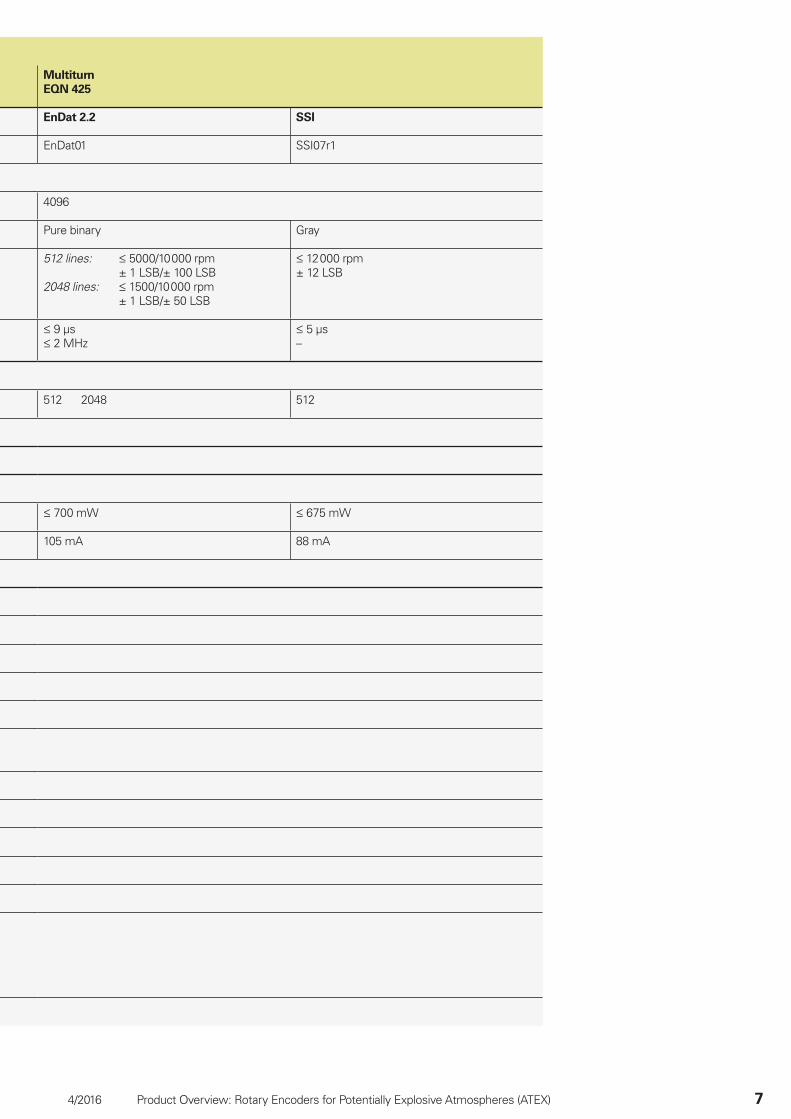
Multiturn
EQN 425
EnDat 2.2 SSI
EnDat01 SSI07r1
4096
Pure binary Gray
512 lines: 5000/10 000 rpm± 1 LSB/± 100 LSB
2048 lines: 1500/10 000 rpm± 1 LSB/± 50 LSB
12 000 rpm± 12 LSB
9 µs 2 MHz
5 µs–
512 2048 512
700 mW 675 mW
105 mA 88 mA
8 Product Overview: Rotary Encoders for Potentially Explosive Atmospheres (ATEX) 4/2016
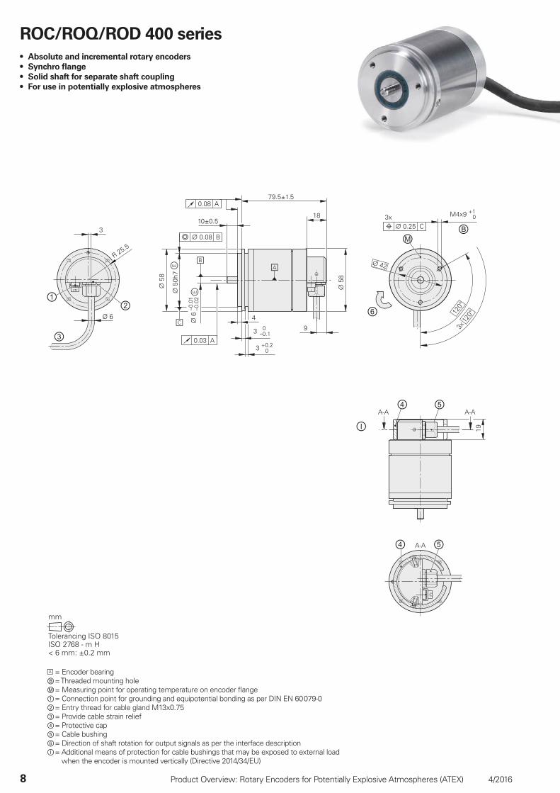
ROC/ROQ/ROD 400 series
• Absolute and incremental rotary encoders
• Synchro fl ange
• Solid shaft for separate shaft coupling
• For use in potentially explosive atmospheres
= Encoder bearingⒷ = Threaded mounting holeⓂ = Measuring point for operating temperature on encoder fl ange① = Connection point for grounding and equipotential bonding as per DIN EN 60 079-0② = Entry thread for cable gland M13x0.75③ = Provide cable strain relief④ = Protective cap⑤ = Cable bushing⑥ = Direction of shaft rotation for output signals as per the interface descriptionⒾ = Additional means of protection for cable bushings that may be exposed to external load
when the encoder is mounted vertically (Directive 2014/34/EU)
4/2016 Product Overview: Rotary Encoders for Potentially Explosive Atmospheres (ATEX) 9
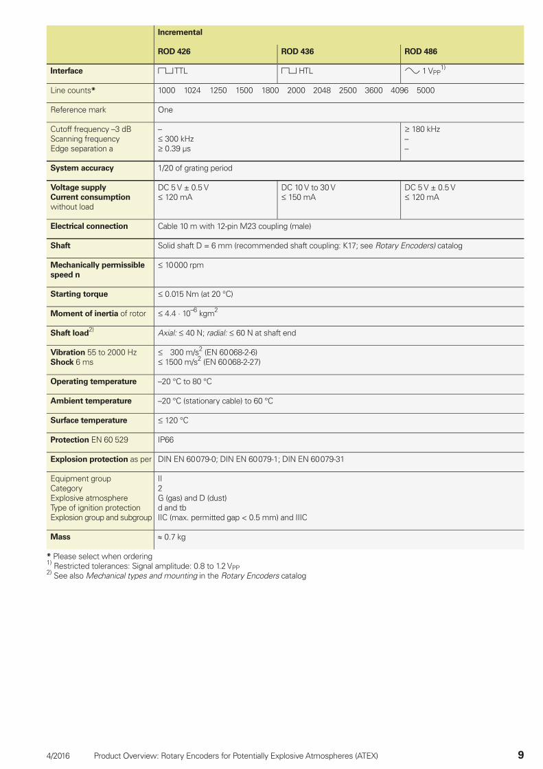
Incremental
ROD 426 ROD 436 ROD 486
Interface TTL HTL 1 VPP1)
Line counts* 1000 1024 1250 1500 1800 2000 2048 2500 3600 4096 5000
Reference mark One
Cutoff frequency –3 dBScanning frequencyEdge separation a
– 300 kHz 0.39 µs
180 kHz––
System accuracy 1/20 of grating period
Voltage supply
Current consumption
without load
DC 5 V ± 0.5 V 120 mA
DC 10 V to 30 V 150 mA
DC 5 V ± 0.5 V 120 mA
Electrical connection Cable 10 m with 12-pin M23 coupling (male)
Shaft Solid shaft D = 6 mm (recommended shaft coupling: K17; see Rotary Encoders) catalog
Mechanically permissible
speed n
10 000 rpm
Starting torque 0.015 Nm (at 20 °C)
Moment of inertia of rotor 4.4 · 10–6 kgm2
Shaft load2) Axial: 40 N; radial: 60 N at shaft end
Vibration 55 to 2000 HzShock 6 ms
300 m/s2 (EN 60 068-2-6) 1500 m/s2 (EN 60 068-2-27)
Operating temperature –20 °C to 80 °C
Ambient temperature –20 °C (stationary cable) to 60 °C
Surface temperature 120 °C
Protection EN 60 529 IP66
Explosion protection as per DIN EN 60 079-0; DIN EN 60 079-1; DIN EN 60 079-31
Equipment groupCategoryExplosive atmosphereType of ignition protectionExplosion group and subgroup
II2G (gas) and D (dust)d and tbIIC (max. permitted gap < 0.5 mm) and IIIC
Mass 0.7 kg
* Please select when ordering1) Restricted tolerances: Signal amplitude: 0.8 to 1.2 VPP2) See also Mechanical types and mounting in the Rotary Encoders catalog
10 Product Overview: Rotary Encoders for Potentially Explosive Atmospheres (ATEX) 4/2016
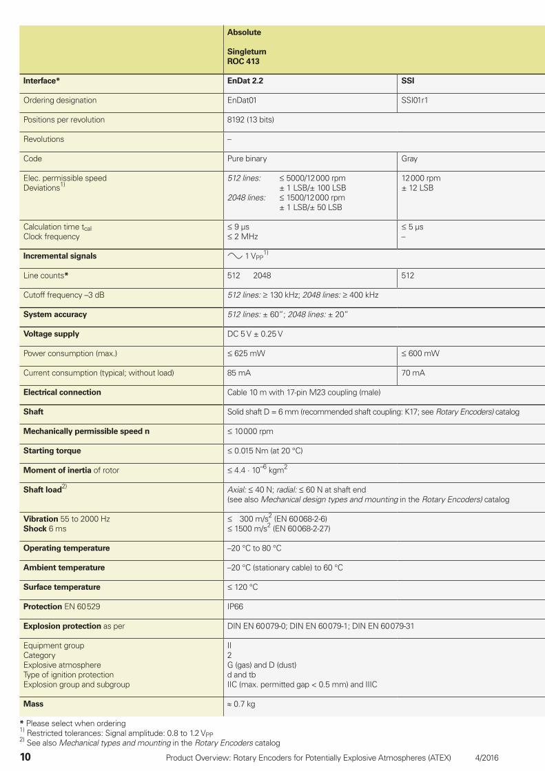
Absolute
Singleturn
ROC 413
Interface* EnDat 2.2 SSI
Ordering designation EnDat01 SSI01r1
Positions per revolution 8192 (13 bits)
Revolutions –
Code Pure binary Gray
Elec. permissible speedDeviations1)
512 lines: 5000/12 000 rpm± 1 LSB/± 100 LSB
2048 lines: 1500/12 000 rpm± 1 LSB/± 50 LSB
12 000 rpm± 12 LSB
Calculation time tcalClock frequency
9 µs 2 MHz
5 µs–
Incremental signals 1 VPP1)
Line counts* 512 2048 512
Cutoff frequency –3 dB 512 lines: 130 kHz; 2048 lines: 400 kHz
System accuracy 512 lines: ± 60”; 2048 lines: ± 20”
Voltage supply DC 5 V ± 0.25 V
Power consumption (max.) 625 mW 600 mW
Current consumption (typical; without load) 85 mA 70 mA
Electrical connection Cable 10 m with 17-pin M23 coupling (male)
Shaft Solid shaft D = 6 mm (recommended shaft coupling: K17; see Rotary Encoders) catalog
Mechanically permissible speed n 10 000 rpm
Starting torque 0.015 Nm (at 20 °C)
Moment of inertia of rotor 4.4 · 10–6 kgm2
Shaft load2) Axial: 40 N; radial: 60 N at shaft end
(see also Mechanical design types and mounting in the Rotary Encoders) catalog
Vibration 55 to 2000 HzShock 6 ms
300 m/s2 (EN 60 068-2-6) 1500 m/s2 (EN 60 068-2-27)
Operating temperature –20 °C to 80 °C
Ambient temperature –20 °C (stationary cable) to 60 °C
Surface temperature 120 °C
Protection EN 60 529 IP66
Explosion protection as per DIN EN 60 079-0; DIN EN 60 079-1; DIN EN 60 079-31
Equipment groupCategoryExplosive atmosphereType of ignition protectionExplosion group and subgroup
II2G (gas) and D (dust)d and tbIIC (max. permitted gap < 0.5 mm) and IIIC
Mass 0.7 kg
* Please select when ordering1) Restricted tolerances: Signal amplitude: 0.8 to 1.2 VPP2) See also Mechanical types and mounting in the Rotary Encoders catalog
4/2016 Product Overview: Rotary Encoders for Potentially Explosive Atmospheres (ATEX) 11
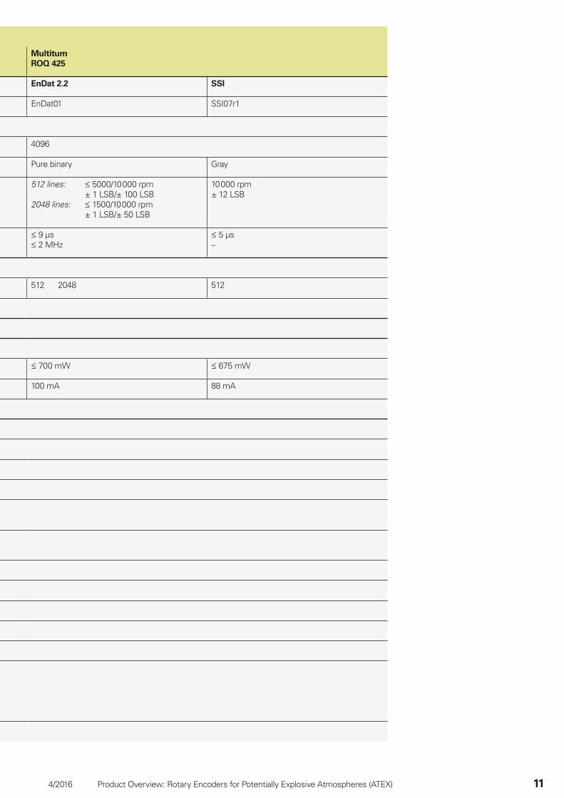
Multiturn
ROQ 425
EnDat 2.2 SSI
EnDat01 SSI07r1
4096
Pure binary Gray
512 lines: 5000/10 000 rpm± 1 LSB/± 100 LSB
2048 lines: 1500/10 000 rpm± 1 LSB/± 50 LSB
10 000 rpm± 12 LSB
9 µs 2 MHz
5 µs–
512 2048 512
700 mW 675 mW
100 mA 88 mA
Ø 6
12 Product Overview: Rotary Encoders for Potentially Explosive Atmospheres (ATEX) 4/2016
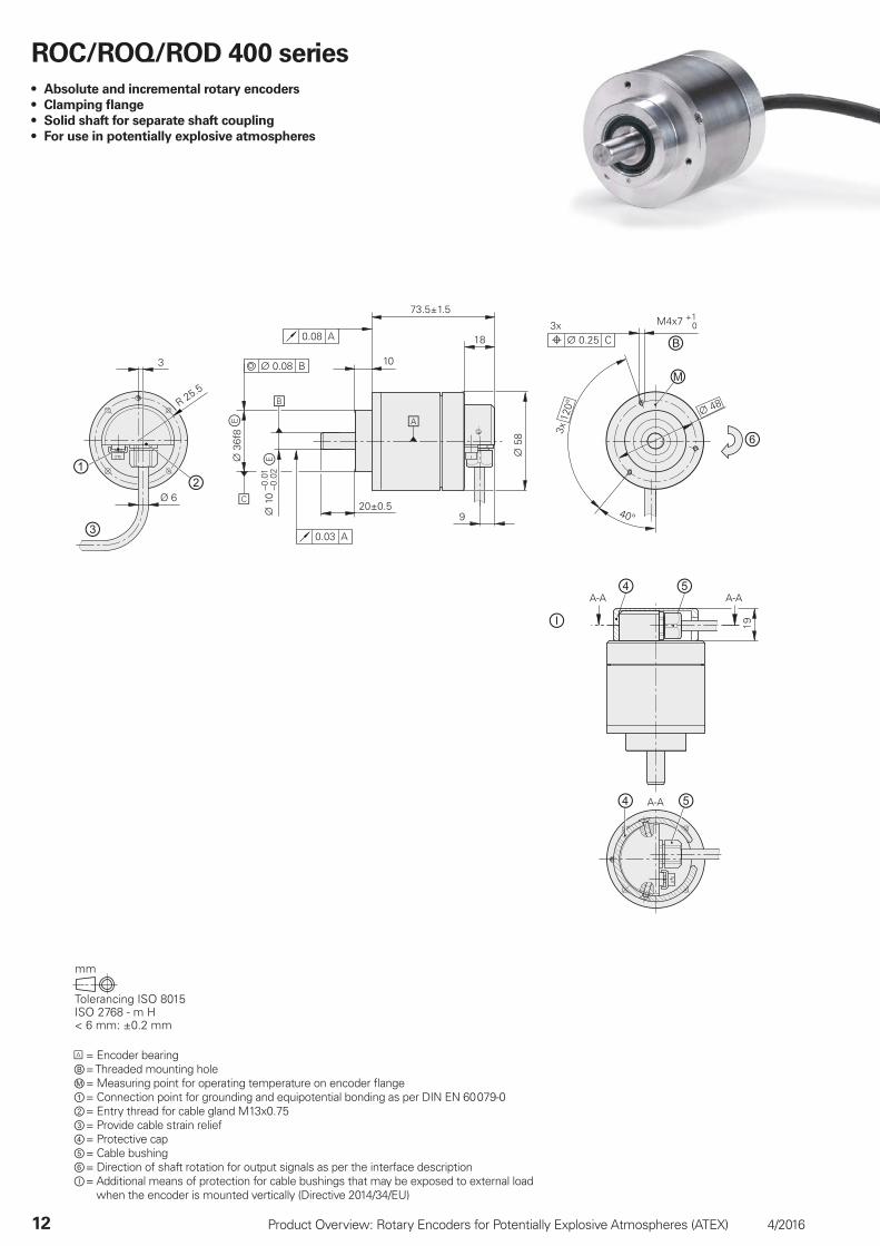
= Encoder bearingⒷ = Threaded mounting holeⓂ = Measuring point for operating temperature on encoder fl ange① = Connection point for grounding and equipotential bonding as per DIN EN 60 079-0② = Entry thread for cable gland M13x0.75③ = Provide cable strain relief④ = Protective cap⑤ = Cable bushing⑥ = Direction of shaft rotation for output signals as per the interface descriptionⒾ = Additional means of protection for cable bushings that may be exposed to external load
when the encoder is mounted vertically (Directive 2014/34/EU)
ROC/ROQ/ROD 400 series
• Absolute and incremental rotary encoders
• Clamping fl ange
• Solid shaft for separate shaft coupling
• For use in potentially explosive atmospheres
4/2016 Product Overview: Rotary Encoders for Potentially Explosive Atmospheres (ATEX) 13
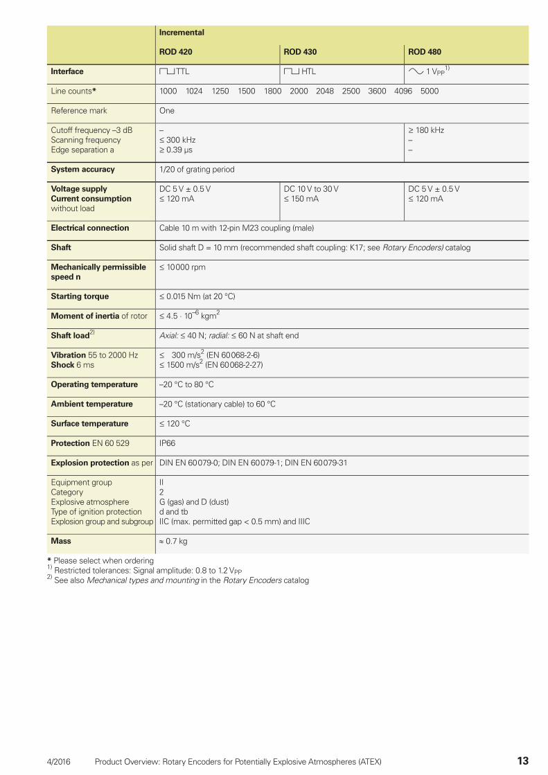
Incremental
ROD 420 ROD 430 ROD 480
Interface TTL HTL 1 VPP1)
Line counts* 1000 1024 1250 1500 1800 2000 2048 2500 3600 4096 5000
Reference mark One
Cutoff frequency –3 dBScanning frequencyEdge separation a
– 300 kHz 0.39 µs
180 kHz––
System accuracy 1/20 of grating period
Voltage supply
Current consumption
without load
DC 5 V ± 0.5 V 120 mA
DC 10 V to 30 V 150 mA
DC 5 V ± 0.5 V 120 mA
Electrical connection Cable 10 m with 12-pin M23 coupling (male)
Shaft Solid shaft D = 10 mm (recommended shaft coupling: K17; see Rotary Encoders) catalog
Mechanically permissible
speed n
10 000 rpm
Starting torque 0.015 Nm (at 20 °C)
Moment of inertia of rotor 4.5 · 10–6 kgm2
Shaft load2) Axial: 40 N; radial: 60 N at shaft end
Vibration 55 to 2000 HzShock 6 ms
300 m/s2 (EN 60 068-2-6) 1500 m/s2 (EN 60 068-2-27)
Operating temperature –20 °C to 80 °C
Ambient temperature –20 °C (stationary cable) to 60 °C
Surface temperature 120 °C
Protection EN 60 529 IP66
Explosion protection as per DIN EN 60 079-0; DIN EN 60 079-1; DIN EN 60 079-31
Equipment groupCategoryExplosive atmosphereType of ignition protectionExplosion group and subgroup
II2G (gas) and D (dust)d and tbIIC (max. permitted gap < 0.5 mm) and IIIC
Mass 0.7 kg
* Please select when ordering1) Restricted tolerances: Signal amplitude: 0.8 to 1.2 VPP2) See also Mechanical types and mounting in the Rotary Encoders catalog

14 Product Overview: Rotary Encoders for Potentially Explosive Atmospheres (ATEX) 4/2016
Absolute
Singleturn
ROC 413
Interface* EnDat 2.2 SSI
Ordering designation EnDat01 SSI01r1
Positions per revolution 8192 (13 bits)
Revolutions –
Code Pure binary Gray
Elec. permissible speedDeviations1)
512 lines: 5000/12 000 rpm± 1 LSB/± 100 LSB
2048 lines: 1500/12 000 rpm± 1 LSB/± 50 LSB
12 000 rpm± 12 LSB
Calculation time tcalClock frequency
9 µs 2 MHz
5 µs–
Incremental signals 1 VPP1)
Line counts* 512 2048 512
Cutoff frequency –3 dB 512 lines: 130 kHz; 2048 lines: 400 kHz
System accuracy 512 lines: ± 60”; 2048 lines: ± 20”
Voltage supply DC 5 V ± 0.25 V
Power consumption (max.) 625 mW 600 mW
Current consumption (typical; without load) 85 mA 70 mA
Electrical connection Cable 10 m with 17-pin M23 coupling (male)
Shaft Solid shaft D = 10 mm (recommended shaft coupling: K17; see Rotary Encoders) catalog
Mechanically permissible speed n 10 000 rpm
Starting torque 0.015 Nm (at 20 °C)
Moment of inertia of rotor 4.5 · 10–6 kgm2
Shaft load2) Axial: 40 N; radial: 60 N at shaft end
(see also Mechanical design types and mounting in the Rotary Encoders) catalog
Vibration 55 to 2000 HzShock 6 ms
300 m/s2 (EN 60 068-2-6) 1500 m/s2 (EN 60 068-2-27)
Operating temperature –20 °C to 80 °C
Ambient temperature –20 °C (stationary cable) to 60 °C
Surface temperature 120 °C
Protection EN 60 529 IP66
Explosion protection as per DIN EN 60 079-0; DIN EN 60 079-1; DIN EN 60 079-31
Equipment groupCategoryExplosive atmosphereType of ignition protectionExplosion group and subgroup
II2G (gas) and D (dust)d and tbIIC (max. permitted gap < 0.5 mm) and IIIC
Mass 0.7 kg
* Please select when ordering1) Restricted tolerances: Signal amplitude: 0.8 to 1.2 VPP2) See also Mechanical types and mounting in the Rotary Encoders catalog
4/2016 Product Overview: Rotary Encoders for Potentially Explosive Atmospheres (ATEX) 15
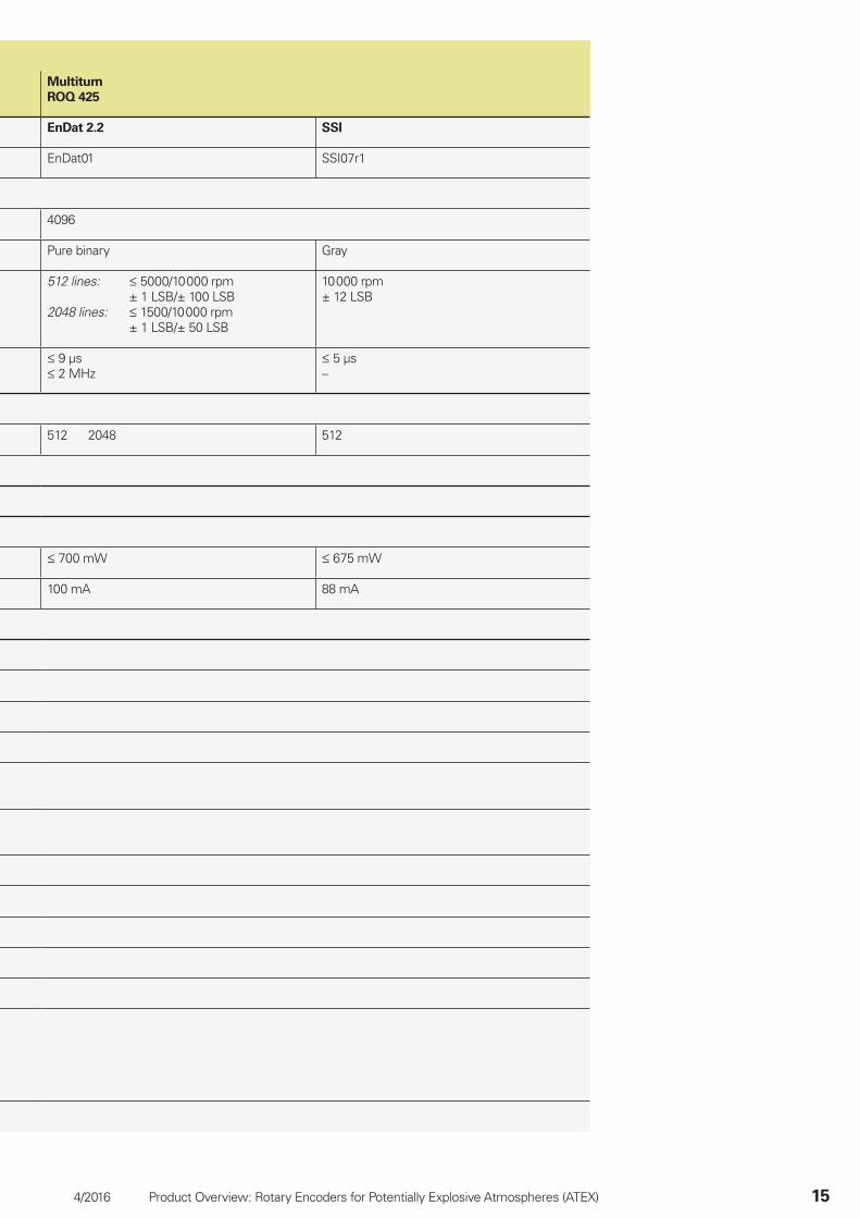
Multiturn
ROQ 425
EnDat 2.2 SSI
EnDat01 SSI07r1
4096
Pure binary Gray
512 lines: 5000/10 000 rpm± 1 LSB/± 100 LSB
2048 lines: 1500/10 000 rpm± 1 LSB/± 50 LSB
10 000 rpm± 12 LSB
9 µs 2 MHz
5 µs–
512 2048 512
700 mW 675 mW
100 mA 88 mA
16 Product Overview: Rotary Encoders for Potentially Explosive Atmospheres (ATEX) 4/2016
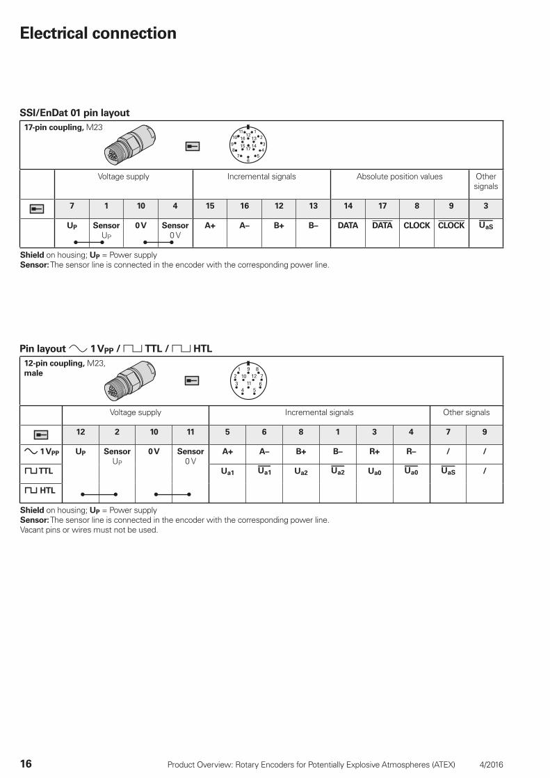
Electrical connection
SSI/EnDat 01 pin layout
17-pin coupling, M23
Voltage supply Incremental signals Absolute position values Other signals
7 1 10 4 15 16 12 13 14 17 8 9 3
UP Sensor
UP
0 V Sensor
0 VA+ A– B+ B– DATA DATA CLOCK CLOCK
Shield on housing; UP = Power supplySensor: The sensor line is connected in the encoder with the corresponding power line.
Pin layout 1 VPP / TTL / HTL
12-pin coupling, M23, male
Voltage supply Incremental signals Other signals
12 2 10 11 5 6 8 1 3 4 7 9
1 VPP UP Sensor
UP
0 V Sensor
0 VA+ A– B+ B– R+ R– / /
TTL Ua1 Ua2 Ua0 /
HTL
Shield on housing; UP = Power supplySensor: The sensor line is connected in the encoder with the corresponding power line.Vacant pins or wires must not be used.
4/2016 Product Overview: Rotary Encoders for Potentially Explosive Atmospheres (ATEX) 17
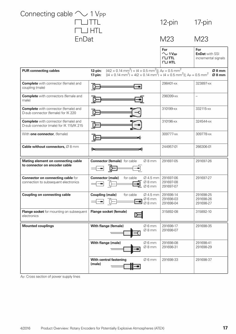
Connecting cable 1 VPP TTL 12-pin 17-pin HTLEnDat M23 M23
For
1 VPP
TTL
HTL
For
EnDat with SSI incremental signals
PUR connecting cables 12-pin: [4(2 × 0.14 mm2) + (4 × 0.5 mm2)]; AP = 0.5 mm2 8 mm
17-pin: [(4 × 0.14 mm2) + 4(2 × 0.14 mm2) + (4 × 0.5 mm2)]; AP = 0.5 mm2 8 mm
Complete with connector (female) and coupling (male)
298401-xx 323897-xx
Complete with connectors (female and male)
298399-xx –
Complete with connector (female) and D-sub connector (female) for IK 220
310199-xx 332115-xx
Complete with connector (female) and D-sub connector (male) for IK 115/IK 215
310196-xx 324544-xx
With one connector, (female) 309777-xx 309778-xx
Cable without connectors, 8 mm 244957-01 266306-01
Mating element on connecting cable
to connector on encoder cable
Connector (female) for cable 8 mm
291697-05 291697-26
Connector on connecting cable for connection to subsequent electronics
Connector (male) for cable 4.5 mm 8 mm 6 mm
291697-06291697-08291697-07
291697-27
Coupling on connecting cable Coupling (male) for cable 4.5 mm 6 mm 8 mm
291698-14291698-03291698-04
291698-25291698-26291698-27
Flange socket for mounting on subsequent electronics
Flange socket (female)
315892-08 315892-10
Mounted couplings
With fl ange (female) 6 mm 8 mm
291698-17291698-07
291698-35
With fl ange (male) 6 mm 8 mm
291698-08291698-31
291698-41291698-29
With central fastening 6 mm(male)
291698-33 291698-37
AP: Cross section of power supply lines

������������ ��� ��������������� ��������������������������������������� �������������� �������������������� !��"�#����������
������ !���� ��!�
677270 · 04 · A · 02 · PDF · 4/2016
This Product Information supersedes all previous editions, which thereby become invalid. The basis for ordering from HEIDENHAIN is always the Product Information valid when the contract is made.
Further Information
• Catalog: Rotary Encoders• Catalog: Interfaces of HEIDENHAIN Encoders