Embed Size (px)
Citation preview

3-Chip DLP ™ Projector
As of April 2013. Specifications and appearance are subject to change without notice.
SFD12M023
1 / 1 7
Product Number : PT-DZ10KProduct Name :
S P E C F I L E

As of April 2013
SFD12M023
2 / 1 7
S P E C F I L E
PT-DZ10K3-Chip DLP™ Projector
Specifications
Main unit
Power supply
Power consumption
DLP™ chip Panel size
Display method
Pixels
Lens
Lamp
Screen size
Brightness* 2
Center-to-corner uniformity* 2
Contrast* 2
Resolution
Scanning frequency SDI
HDMI/DVI-D/RGB
YPBPR (YCBCR)
120 V AC, 9 A, 50/60 Hz
220–240 V AC, 4.7 A, 50/60 Hz
925 W (1,010 VA) (0.2 W with standby mode set to eco.*1 6 W with
standby mode set to normal. Both with fan stopped.)
900 W (980 VA) (0.3 W with standby mode set to eco.*1 9 W with standby
mode set to normal. Both with fan stopped.)
24.4 mm (0.96 inches) diagonal (16:10 aspect ratio)
DLP™ chip × 3 (R, G, B), DLP™ projection system
2,304,000 (1,920 × 1,200) × 3, total of 6,912,000 pixels
Optional powered zoom/focus lenses
355 W UHM lamps (× 2) (dual lamp, normal mode)
1.78–25.4 m (70 – 1,000 inches) (1.78–15.24 m (70– 600 inches) with the
ET-D75LE8), 16:10 aspect ratio
10,600 lumens (dual lamp, normal mode)
90%
10,000:1 (full on/full off, in dynamic iris 3 mode)
1,920 × 1,200 pixels
3G-SDI signal (RGB 4:4:4 12-bit/10-bit):
SMPTE ST 424 compliant: 1125(1080)/60i, 1125(1080)/50i,
1125(1080)/25p, 1125(1080)/24p, 1125(1080)/24sF, 1125(1080)/30p
3G-SDI signal (YPBPR 4:2:2 10-bit):
SMPTE ST 424 compliant: 1125(1080)/60p, 1125(1080)/50p
HD-SDI signal (YPBPR 4:2:2 10-bit):
SMPTE ST 292 compliant: 750(720)/60p, 750(720)/50p, 1125(1035)/60i,
1125(1080)/60i, 1125(1080)/50i, 1125(1080)/25p, 1125(1080)/24p,
1125(1080)/24sF, 1125(1080)/30p
SD-SDI signal (YCBCR 4:2:2 10-bit):
SMPTE ST 259 compliant: 525i(480i), 625i(576i)
Horizontal: 15 kHz–100 kHz, vertical: 24 Hz – 120 Hz,
dot clock: 25 –162 MHz or lower (HDMI/DVI: 25 MHz – 162 MHz)
525i (480i): fH 15.75 kHz; fV 60 Hz,
625i (576i): fH 15.63 kHz; fV 50 Hz,
525p (480p): fH 31.50 kHz; fV 60 Hz,
625p (576p): fH 31.25 kHz; fV 50 Hz,
750 (720)/60p: fH 45.00 kHz; fV 60 Hz,
750 (720)/50p: fH 37.50 kHz; fV 50 Hz,
1125 (1035)/60i: fH 33.75 kHz; fV 60 Hz,
1125 (1080)/60i: fH 33.75 kHz; fV 60 Hz,
1125 (1080)/50i: fH 28.13 kHz; fV 50 Hz,
1125 (1080)/25p: fH 28.13 kHz; fV 25 Hz,
1125 (1080)/24p: fH 27.00 kHz; fV 24 Hz,
1125 (1080)/24sF: fH 27.00 kHz; fV 48 Hz,
1125 (1080)/30p: fH 33.75 kHz; fV 30 Hz,
1125 (1080)/60p: fH 67.50 kHz; fV 60 Hz,
1125 (1080)/50p: fH 56.25 kHz; fV 50 Hz
120 V AC, 50/60 Hz
220–240 V AC, 50/60 Hz
fH: 15.75 kHz, fV: 60 Hz [NTSC/NTSC4.43/PAL-M/PAL60]
fH: 15.63 kHz, fV: 50 Hz [PAL/PAL-N/SECAM]
Video/S-Video
Optical axis shift Vertical
Horizontal
±55% (±44% with the ET-D75LE6) from center of screen, powered
±20% (±15% with the ET-D75LE6) from center of screen, poweredNOTE: Optical axis shift function cannot be operated when used with the
ET-D75LE50.

As of April 2013
SFD12M023
3 / 1 7
S P E C F I L E
PT-DZ10K3-Chip DLP™ Projector
Keystone correction range
Installation
Terminals SDI IN
HDMI IN
DVI-D IN
RGB 1 IN
R, G, B
Y, PB, PR (Y, CB, CR)
S-Video signal
RGB 2 IN
R, G, B
Y, PB, PR (Y, CB, CR)
VIDEO IN
Vertical ±40°, horizontal ±15°
(vertical ±22° and horizontal ±15° with the ET-D75LE5/LE50,
vertical ±28° and horizontal ±15° with the ET-D75LE6)
When using only the KEYSTONE correction of the Geometric Adjustment
function: Vertical ±40°, horizontal ±15°
Ceiling/floor, front/rear
BNC × 1,
3G-SDI signal: SMPTE ST 424 compliant
HD-SDI signal: SMPTE ST 292 compliant
SD-SDI signal: SMPTE ST 259 compliant
HDMI 19-pin × 1, Deep Color, compatible with HDCP,
VGA (640 × 480) – WUXGA*4 (1,920 × 1,200),
dot clock: 25 MHz –162 MHzNOTE: Compatible with non-interlaced signals only.
DVI-D 24-pin × 1, DVI 1.0 compliant, HDCP compatible,
for single link only
525i(480i)*3, 625i(576i)*3, 525p(480p), 625p(576p), 750(720)/60p,
750(720)50p, 1125(1080)/60i, 1125(1080)/50i, 1125(1080)/25p,
1125(1080)/24p, 1125(1080)/24sF, 1125(1080)/30p, 1125(1080)/60p,
1125(1080)/50pVGA (640 × 480) – WUXGA*4 (1,920 × 1,200),
dot clock: 25 MHz –162 MHzNOTE: Compatible with non-interlaced signals only.
BNC × 5
R: 0.7 Vp-p, 75 ohms,
G: 0.7 Vp-p (G: 1.0 Vp-p for sync on G), 75 ohms,
B: 0.7 Vp-p, 75 ohms
HD, VD/SYNC: TTL, high impedance, positive/negative automaticNOTE: SYNC/HD and VD terminals do not accept tri-level sync signals.
Y: 1.0 Vp-p (including sync signal), PB/PR (CB/CR): 0.7 Vp-p, 75 ohms
Y: 1.0 Vp-p, C: 0.286 Vp-p, 75 ohms
D-sub HD 15-pin (female) × 1
R: 0.7 Vp-p, 75 ohms,
G: 0.7 Vp-p (G: 1.0 Vp-p for sync on G), 75 ohms,
B: 0.7 Vp-p, 75 ohms
HD, VD/SYNC: TTL, high impedance, positive/negative automaticNOTE: SYNC/HD and VD terminals do not accept tri-level sync signals.
Y: 1.0 Vp-p (including sync signal), PB/PR (CB/CR): 0.7 Vp-p, 75 ohms
BNC × 1, 1.0 Vp-p, 75 ohms
525i(480i)*3, 625i(576i)*3, 525p(480p), 625p(576p), 750(720)/60p,
750(720)50p, 1125(1080)/60i, 1125(1080)/50i, 1125(1080)/25p,
1125(1080)/24p, 1125(1080)/24sF, 1125(1080)/30p, 1125(1080)/60p,
1125(1080)/50p
REMOTE 2 IN
LAN
D-sub 9-pin × 1 for external control (parallel)
RJ-45 × 1 for network connection, 100Base-TX/10Base-T, compliant
with PJLink™ (class 1)
SERIAL IN
SERIAL OUT
REMOTE 1 IN
REMOTE 1 OUT
D-sub 9-pin (female) × 1 for external control (RS-232C compliant)
D-sub 9-pin (male) × 1 for link control
M3 jack × 1 for wired remote control
M3 jack × 1 for link control
(RS-232C compliant)
Power cord length
Cabinet materials
3.0 m (9 10 in)
Molded plastic
Dimensions (W × H × D):
Weight*6
Operation noise*2
530 × 200*5 × 548.5 mm
(20-7/8 × 7-7/8*5 × 21-19/32 inches) (without lens)
24 kg (52.9 lbs) (without lens)
43 dB (normal mode), 37 dB (eco mode)
Operating temperature
Operating humidity
0°– 45°C (32°–113°F) * 7
10%–80% (no condensation)

As of April 2013
SFD12M023
4 / 1 7
S P E C F I L E
PT-DZ10K3-Chip DLP™ Projector
Remote control unit
Power supply
Operation range*8
Dimensions (W × H × D)
Weight
Supplied accessories
Optional accessories
Zoom lens (0.9 –1.1:1)
Zoom lens (1.3– 1.7:1)
Zoom lens (1.7– 2.4:1)
Zoom lens (2.4– 4.7:1)
Zoom lens (4.6– 7.4:1)
Zoom lens (7.3– 13.8:1)
Fixed-focus lens (0.7:1)
Lens motor cover
Ceiling mount bracket
Frame
Smoke cut filter
Replacement lamp unit
Replacement lamp unit for portrait mode
Replacement filter unit
3 V DC (AA/R6 type battery × 2)
Approx. 30 m (98 5 in) when operated from directly in front of the
signal receptor
51 × 176 × 28 mm (2 × 6-15/16 × 1-3/32 inches)
Approx. 134 g (4.7 oz) (including batteries)
Power cord (×1) (x2 for PT-DZ10KE)
Wireless/wired remote control unit (× 1)
Batteries for remote control (AA/R6 type × 2)
Softwar
Lens drop-prevention screw (× 1)
e CD-ROM (Logo Transfer Software, Multi Projector Monitoring
& Control Software) (× 1)
ET-D75LE6
ET-D75LE10
ET-D75LE20
ET-D75LE30
ET-D75LE40
ET-D75LE8
ET-D75LE50
ET-D75MC1
ET-PKD310H (for high ceilings)
ET-PKD310S (for low ceilings)
ET
Attachment for ceiling mount bracket ET-PAD310
-PFD310
ET
Replacement smoke cut filter ET-SFR320
-SFD320
ET-LAD310A (one bulb)
ET-LAD310AW (a set of two bulbs)
ET-LAD320P (one bulb)
ET-LAD320PW (a set of two bulbs)
ET-EMF320
Weights and dimensions shown are approximate. Specifications and appearance are subject to change without notice.
*1 When the standby mode is set to eco, network functions such as power on over the LAN network will not operate, and the serial output termi-nal cannot be used. Also, only certain commands can be received for external control using the serial terminal.
*2 Measurement, measuring conditions, and method of notation all comply with ISO 21118 international standards.
*3 Only compatible with dot clock frequency of 27 MHz (pixel repetition signal)
*4 WUXGA resolution is supported only when the signals are compliant with VESA CVT-RB (Coordinated Video Timing-Reduced Blanking).
*5 With legs at shortest position.
*6 Average value (excluding the optional lens). May differ depending on models.*7 The operating temperature range is 0 °C to 40 °C (32 °F to 104 °F) when the FAN CONTROL is set to HIGH ALTITUDE MODE (for altitudes from
1,400 m to 2,700 m (4,593 ft to 8,858 ft) above sea level). When the projector is used with the ET-SFD320 Smoke Cut Filter, the operating temperature range is 0 °C to 35 °C (32 °F to 95 °F), and the projector cannot be used in places at high altitude. The operating temperature range is 0 °C to 40 °C (32 °F to 104 °F) when the ET-LAD320P/LAD320PW lamp is mounted and the projector is used in portrait configuration. The operating temperature range is 0 °C to 35 °C (32 °F to 95 °F) when the FAN CONTROL is set to HIGH ALTITUDE MODE (for altitudes from 1,400 m to 2,700 m (4,593 ft to 8,858 ft) above sea level). When the projector is used with the ET-SFD320 Smoke Cut Filter, the operating temperature range is 0 °C to 30 °C (32 °F to 86 °F).
*8 Operation range differs depending on environments.

As of April 2013
SFD12M023
5 / 1 7
S P E C F I L E
PT-DZ10K3-Chip DLP™ Projector
Dimensions
Terminals
1 Remote 1 input
2 Remote 1 output
3 Remote 2 input
4 Serial input
5 Serial output
6 SDI input
7 HDMI input
8 RGB 1 input
9 RGB 2 Input
10 DVI-D input
11 Video input
12 LAN connector
unit : mm (inch)NOTE: This illustration is not drawn to scale.
540
(21-
1/4)
548.
5 (2
1-19
/32)
8.5
(11/
32)
530 (20-7/8)
462 (18-3/16) 468 (18-7/16)26(1-1/32)
100
(3-1
5/16
)
200
(7-7
/8)

As of April 2013
SFD12M023
6 / 1 7
S P E C F I L E
PT-DZ10K3-Chip DLP™ Projector
Standard setting-up position
unit : mm (inch)
*1 When the lens protrudes to the maximum.212 mm (8-11/32) with the ET-D75LE6125 mm (4-29/32) with the ET-D75LE10121 mm (4-3/4) with the ET-D75LE20121 mm (4-3/4) with the ET-D75LE30124 mm (4-7/8) with the ET-D75LE40254 mm (10) with the ET-D75LE8203 mm (8) with the ET-D75LE50
*2 Adjustable in 40 mm (1-9/16) steps.
C a u t i o n :• All construction work should be done by a qualified technician.• When mounting to the ceiling, use the special mounting bracket.
Furthermore, in order to prevent it from falling down from the ceiling, use the supplied wire on the mounting bracket.
NOTE:
Illustrations show the projector installedusing optional ceiling mount bracket ET-PKD310H and an optional lens.
This illustration is not drawn to scale.
Projected image
HH
Lower edge of projected image
Upper edge of projected image
L
Projected image
L
L
*2 *2
*1
340~
420
436~
516
342 (13-15/32)
198(7-25/32)
φ60.5(12-3/8)
100
(3-1
5/16
)10
0(3
-15/
16)
100(3-15/16)
100(3-15/16)
(13-
3/8–
16-1
7/32
)
(17-
5/32
–20
-5/1
6)

As of April 2013
SFD12M023
7 / 1 7
[m] / [in]
/
/
/
/
/
/
/
/
/
/
/
/
1.78
2.03
2.29
2.54
3.05
3.81
5.08
6.35
7.62
10.16
12.70
15.24
70
80
90
100
120
150
200
250
300
400
500
600
Screen size(diagonal)
Zoom
Zoom lenses
Fixed-focus
Fixed-focuslens
Distance to screen (L) Height from the edge of screen to center of lens (H)
ET-D75LE10Zoom lens
min. max. min. max. min. max. min. max. min. max. min. max.
ET-D75LE6Zoom lens
ET-D75LE20Zoom lens
ET-D75LE30Zoom lens
ET-D75LE40Zoom lens
ET-D75LE8Zoom lens
ET-D75LE50Fixed-focus
lensExcept
ET-D75LE6ET-D75LE6
–
–
–
–
–
–
–
–
–
–
–
–
0.06
0.07
0.07
0.08
0.10
0.12
0.16
0.20
0.24
0.32
0.40
0.49
0.89
1.01
1.14
1.27
1.52
1.90
2.53
3.16
3.80
5.06
6.33
7.59
–
–
–
–
–
–
–
–
–
–
–
–
-0.05
-0.05
-0.06
-0.07
-0.08
-0.10
-0.14
-0.17
-0.20
-0.27
-0.34
-0.40
0.99
1.13
1.27
1.41
1.70
2.12
2.83
3.53
4.24
5.65
7.07
8.48
1.01
1.16
1.32
1.47
1.78
2.24
3.01
3.78
4.56
6.10
7.64
9.18
0.47
0.54
0.61
0.67
0.81
1.01
1.35
1.68
2.02
2.69
3.37
4.04
1.62
1.86
2.10
2.34
2.82
3.55
4.75
5.96
7.17
9.58
11.99
14.40
2.46
2.83
3.20
3.56
4.30
5.40
7.24
9.07
10.91
14.58
18.25
21.93
3.58
4.11
4.64
5.17
6.22
7.81
10.45
13.09
15.73
21.01
26.29
31.58
6.94
7.96
8.98
9.99
12.03
15.08
20.17
25.25
30.34
40.51
50.68
60.85
11.05
12.65
14.25
15.85
19.05
23.85
31.86
39.86
47.87
63.87
79.88
95.89
20.56
23.55
26.54
29.53
35.51
44.47
59.41
74.36
89.30
119.19
149.08
178.96
1.35
1.56
1.76
1.96
2.36
2.96
3.97
4.98
5.99
8.00
10.01
12.03
1.90
2.19
2.47
2.76
3.32
4.18
5.60
7.02
8.44
11.28
14.12
16.96
2.46
2.83
3.19
3.55
4.28
5.37
7.19
9.01
10.82
14.46
18.09
21.73
3.56
4.08
4.61
5.13
6.18
7.75
10.38
13.00
15.62
20.86
26.11
31.35
6.87
7.88
8.88
9.88
11.89
14.90
19.93
24.95
29.97
40.01
50.05
60.09
10.78
12.38
13.97
15.57
18.76
23.54
31.52
39.49
47.47
63.42
79.37
95.32
/17.78 700
/20.32 800
/22.86 900
/25.40 1000
[m] / [in]
/
/
/
/
/
/
/
/
/
/
/
/
1.78
2.03
2.29
2.54
3.05
3.81
5.08
6.35
7.62
10.16
12.70
15.24
70
80
90
100
120
150
200
250
300
400
500
Screen size(diagonal)
Zoom
Zoom lenses
Fixed-focus
Fixed-focuslens
Distance to screen (L) Height from the edge of screen to center of lens (H)
ET-D75LE10Zoom lens
min. max. min. max. min. max. min. max. min. max. min. max.
ET-D75LE6Zoom lens
ET-D75LE20Zoom lens
ET-D75LE30Zoom lens
ET-D75LE40Zoom lens
ET-D75LE8Zoom lens
ET-D75LE50Fixed-focus
lensExcept
ET-D75LE6ET-D75LE6
–
–
–
–
–
–
–
–
–
–
–
–
0.2
0.2
0.2
0.3
0.3
0.4
0.5
0.7
0.8
1.1
1.3
1.6
2.9
3.3
3.7
4.2
5.0
6.2
8.3
10.4
12.5
16.6
20.8
24.9
–
–
–
–
–
–
–
–
–
–
–
–
-0.2
-0.2
-0.2
-0.2
-0.3
-0.3
-0.4
-0.6
-0.7
-0.9
-1.1
-1.3
3.2
3.7
4.2
4.6
5.6
7.0
9.3
11.6
13.9
18.6
23.2
27.8
3.3
3.8
4.3
4.8
5.8
7.3
9.8
12.3
14.9
20.0
25.1
1.6
1.8
2.0
2.2
2.7
3.3
4.4
5.5
6.6
8.8
11.0
5.3
6.1
6.9
7.7
9.3
11.6
15.6
19.6
23.5
31.4
39.3
47.3
8.1
9.3
10.5
11.7
14.1
17.7
23.7
29.8
35.8
47.8
59.9
71.9
11.7
13.5
15.2
16.9
20.4
25.6
34.3
42.9
51.6
68.9
86.3
103.6
22.8
26.1
29.5
32.8
39.5
49.5
66.2
82.8
99.5
132.9
166.3
199.6
36.2
41.5
46.7
52.0
62.5
78.3
104.5
130.8
157.0
209.6
262.1
314.6
67.5
77.3
87.1
96.9
116.5
145.9
194.9
244.0
293.0
391.0
489.1
587.1
4.4
5.1
5.8
6.4
7.7
9.7
13.0
16.3
19.6
26.2
32.9
39.5
6.2
7.2
8.1
9.0
10.9
13.7
18.4
23.0
27.7
37.0
46.3
55.6
8.1
9.3
10.5
11.7
14.0
17.6
23.6
29.5
35.5
47.4
59.4
71.3
11.7
13.4
15.1
16.8
20.3
25.4
34.0
42.6
51.2
68.5
85.7
102.9
22.5
25.8
29.1
32.4
39.0
48.9
65.4
81.8
98.3
131.3
164.2
197.1
35.4
40.6
45.8
51.1
61.5
77.2
103.4
129.6
155.7
208.1
260.4
312.7
Projection distance for 16:10 aspect ratio screen(ET-D75LE6/D75LE10/D75LE20/D75LE30/D75LE40/D75LE8/D75LE50)
Unit: feet
Unit: meters
• The value for L (distance to screen) varies slightly within ±5% depending on the zoom lens characteristics.
• At the shortest projection distance, the zoom lens characteristics may cause slight image distortion.
• When vertical keystone correction is used, the image is corrected in the direction that reduces its projected size.
NOTE: When the ET-D75LE50 is mounted, the optical lens shift function cannot be used.
14.04 16.82 19.80 25.60 25.36 36.86 36.60 71.02 70.13 111.90 111.27 – 10.72 -0.47 – 9.90 0.57 – 8.86 4.71
16.06 19.23 22.64 29.27 29.00 42.14 41.84 81.19 80.17 127.91 127.23 – 12.27 -0.54 – 11.31 0.65 – 10.12 5.39
18.07 21.64 25.48 32.94 32.63 47.42 47.09 91.36 90.21 143.92 143.12 – 13.81 -0.61 – 12.72 0.73 – 11.39 6.06
20.08 24.06 28.33 36.61 36.27 52.70 52.33 101.53 100.25 159.93 159.13 – 15.35 -0.67 – 14.14 0.81 – 12.65 6.73
600 30.1 13.3
/17.78 700
/20.32 800
/22.86 900
/25.40 1000
46.1 55.2 65.0 84.0 83.2 120.9 120.1 233.0 230.1 367.1 365.1 – 35.2 -1.5 – 32.5 1.9 – 29.1 15.5
52.7 63.1 74.3 96.0 95.1 138.3 137.3 266.4 263.0 419.6 417.4 – 40.2 -1.8 – 37.1 2.1 – 33.2 17.7
59.3 71.0 83.6 108.1 107.1 155.6 154.5 299.7 296.0 472.2 469.5 – 45.3 -2.0 – 41.7 2.4 – 37.4 19.9
65.9 78.9 92.9 120.1 119.0 172.9 171.7 333.1 328.9 524.7 522.1 – 50.4 -2.2 – 46.4 2.7 – 41.5 22.1
S P E C F I L E
PT-DZ10K3-Chip DLP™ Projector

As of April 2013
SFD12M023
8 / 1 7
S P E C F I L E
PT-DZ10K3-Chip DLP™ Projector
[m] / [in]
/
/
/
/
/
/
/
/
/
/
/
/
1.78
2.03
2.29
2.54
3.05
3.81
5.08
6.35
7.62
10.16
12.70
15.24
70
80
90
100
120
150
200
250
300
400
500
600
Screen size(diagonal)
Zoom
Zoom lenses
Fixed-focus
Fixed-focuslens
Distance to screen (L) Height from the edge of screen to center of lens (H)
ET-D75LE10Zoom lens
min. max. min. max. min. max. min. max. min. max. min. max.
ET-D75LE6Zoom lens
ET-D75LE20Zoom lens
ET-D75LE30Zoom lens
ET-D75LE40Zoom lens
ET-D75LE8Zoom lens
ET-D75LE50Fixed-focus
lensExcept
ET-D75LE6ET-D75LE6
–
–
–
–
–
–
–
–
–
–
–
–
0.00
0.00
0.00
0.00
0.00
0.00
0.00
0.00
0.00
0.00
0.00
0.00
0.87
1.00
1.12
1.25
1.49
1.87
2.49
3.11
3.74
4.98
6.23
7.47
–
–
–
–
–
–
–
–
–
–
–
–
-0.09
-0.10
-0.11
-0.13
-0.15
-0.19
-0.25
-0.31
-0.37
-0.50
-0.62
-0.75
0.96
1.10
1.23
1.37
1.64
2.06
2.74
3.42
4.11
5.48
6.85
8.22
1.04
1.20
1.36
1.51
1.83
2.31
3.10
3.89
4.68
6.29
7.85
9.44
0.44
0.50
0.56
0.62
0.75
0.93
1.25
1.56
1.87
2.49
3.11
3.74
1.66
1.91
2.16
2.41
2.90
3.65
4.89
6.13
7.37
9.85
12.33
14.81
2.53
2.91
3.29
3.67
4.42
5.55
7.44
9.33
11.21
14.99
18.76
22.54
3.68
4.23
4.77
5.31
6.40
8.03
10.74
13.46
16.17
21.60
27.03
32.46
7.14
8.19
9.23
10.28
12.37
15.50
20.73
25.96
31.18
41.64
52.09
62.54
11.36
13.00
14.65
16.29
19.58
24.52
32.75
40.97
49.20
65.65
82.11
98.56
21.14
24.22
27.29
30.36
36.50
45.72
61.08
76.44
91.79
122.51
153.23
183.95
1.39
1.60
1.81
2.01
2.43
3.05
4.08
5.12
6.15
8.22
10.29
12.36
1.96
2.25
2.54
2.83
3.42
4.29
5.76
7.22
8.68
11.60
14.52
17.44
2.53
2.91
3.28
3.65
4.40
5.52
7.39
9.26
11.13
14.86
18.60
22.33
3.66
4.20
4.74
5.28
6.36
7.97
10.67
13.36
16.06
21.45
26.84
32.23
7.07
8.10
9.13
10.16
12.23
15.32
20.48
25.64
30.80
41.12
51.44
61.76
11.09
12.73
14.37
16.01
19.29
24.21
32.40
40.60
48.80
65.19
81.59
97.98
[m] / [in]
/
/
/
/
/
/
/
/
/
/
/
/
1.78
2.03
2.29
2.54
3.05
3.81
5.08
6.35
7.62
10.16
12.70
15.24
70
80
90
100
120
150
200
250
300
400
500
600
Screen size(diagonal)
Zoom
Zoom lenses
Fixed-focus
Fixed-focuslens
Distance to screen (L) Height from the edge of screen to center of lens (H)
ET-D75LE10Zoom lens
min. max. min. max. min. max. min. max. min. max. min. max.
ET-D75LE6Zoom lens
ET-D75LE20Zoom lens
ET-D75LE30Zoom lens
ET-D75LE40Zoom lens
ET-D75LE8Zoom lens
ET-D75LE50Fixed-focus
lensExcept
ET-D75LE6ET-D75LE6
–
–
–
–
–
–
–
–
–
–
–
–
0.0
0.0
0.0
0.0
0.0
0.0
0.0
0.0
0.0
0.0
0.0
0.0
2.9
3.3
3.7
4.1
4.9
6.1
8.2
10.2
12.3
16.3
20.4
24.5
–
–
–
–
–
–
–
–
–
–
–
–
-0.3
-0.3
-0.4
-0.4
-0.5
-0.6
-0.8
-1.0
-1.2
-1.6
-2.0
-2.5
3.2
3.6
4.1
4.5
5.4
6.7
9.0
11.2
13.5
18.0
22.5
27.0
3.4
3.9
4.4
5.0
6.0
7.6
10.2
12.8
15.4
20.6
25.8
31.0
1.4
1.6
1.8
2.0
2.5
3.1
4.1
5.1
6.1
8.2
10.2
12.3
5.5
6.3
7.1
7.9
9.5
12.0
16.0
20.1
24.2
32.3
40.4
48.6
8.3
9.6
10.8
12.0
14.5
18.2
24.4
30.6
36.8
49.2
61.6
73.9
12.1
13.9
15.6
17.4
21.0
26.3
35.2
44.1
53.1
70.9
88.7
106.5
23.4
26.9
30.3
33.7
40.6
50.9
68.0
85.2
102.3
136.6
170.9
205.2
37.3
42.7
48.1
53.5
64.2
80.4
107.4
134.4
161.4
215.4
269.4
323.4
69.4
79.4
89.5
99.6
119.8
150.0
200.4
250.8
301.2
401.9
502.7
603.5
4.6
5.2
5.9
6.6
8.0
10.0
13.4
16.8
20.2
27.0
33.8
40.6
6.4
7.4
8.3
9.3
11.2
14.1
18.9
23.7
28.5
38.0
47.6
57.2
8.3
9.5
10.8
12.0
14.4
18.1
24.2
30.4
36.5
48.8
61.0
73.3
12.0
13.8
15.5
17.3
20.8
26.2
35.0
43.8
52.7
70.4
88.0
105.7
23.2
26.6
30.0
33.3
40.1
50.3
67.2
84.1
101.1
134.9
168.8
202.6
36.4
41.8
47.1
52.5
63.3
79.4
106.3
133.2
160.1
213.9
267.7
321.5
Projection distance for 16:9 aspect ratio screen(ET-D75LE6/D75LE10/D75LE20/D75LE30/D75LE40/D75LE8/D75LE50)
Unit: feet
Unit: meters
• The value for L (distance to screen) varies slightly within ±5% depending on the zoom lens characteristics.
• At the shortest projection distance, the zoom lens characteristics may cause slight image distortion.
• When vertical keystone correction is used, the image is corrected in the direction that reduces its projected size.
NOTE: When the ET-D75LE50 is mounted, the optical lens shift function cannot be used.
/17.78 700
/20.32 800
/22.86 900
/25.40 1000
47.4 56.7 66.8 86.3 85.5 124.3 123.4 239.5 236.5 377.3 375.3 – 36.2 -2.9 – 31.5 0.0 – 28.6 14.3
54.1 64.8 76.4 98.7 97.8 142.1 141.1 273.8 270.5 431.3 429.0 – 41.4 -3.3 – 36.0 0.0 – 32.7 16.3
60.9 73.0 85.9 111.1 110.0 159.9 158.8 308.1 304.2 485.3 482.8 – 46.6 -3.7 – 40.4 0.0 – 36.8 18.4
67.7 81.1 95.5 123.5 122.3 177.7 176.5 342.4 338.1 539.3 536.6 – 51.8 -4.1 – 44.9 0.0 – 40.9 20.4
/17.78 700
/20.32 800
/22.86 900
/25.40 1000
14.43 17.29 20.36 26.31 26.07 37.89 37.62 73.00 72.09 115.02 114.38 – 11.02 -0.87 – 9.59 0.00 – 8.72 4.36
16.50 19.77 23.28 30.09 29.81 43.31 43.01 83.45 82.45 131.47 130.77 – 12.61 -1.00 – 10.96 0.00 – 9.96 4.98
18.57 22.25 26.20 33.86 33.54 48.74 48.40 93.90 92.73 147.92 147.17 – 14.19 -1.12 – 12.33 0.00 – 11.21 5.60
20.64 24.73 29.12 37.64 37.28 54.17 53.79 104.36 103.05 164.38 163.56 – 15.78 -1.25 – 13.70 0.00 –12.45 6.23
As of April 2013
SFD12M023
9 / 1 7
S P E C F I L E
PT-DZ10K3-Chip DLP™ Projector
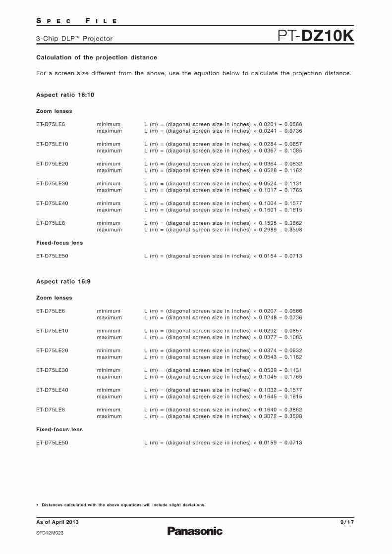
Calculation of the projection distance
For a screen size different from the above, use the equation below to calculate the projection distance.
Aspect ratio 16:10
minimum L (m) = (diagonal screen size in inches) × 0.0201 – 0.0566maximum L (m) = (diagonal screen size in inches) × 0.0241 – 0.0736
minimum L (m) = (diagonal screen size in inches) × 0.0284 – 0.0857maximum L (m) = (diagonal screen size in inches) × 0.0367 – 0.1085
minimum L (m) = (diagonal screen size in inches) × 0.0364 – 0.0832maximum L (m) = (diagonal screen size in inches) × 0.0528 – 0.1162
minimum L (m) = (diagonal screen size in inches) × 0.0524 – 0.1131maximum L (m) = (diagonal screen size in inches) × 0.1017 – 0.1765
minimum L (m) = (diagonal screen size in inches) × 0.1004 – 0.1577maximum L (m) = (diagonal screen size in inches) × 0.1601 – 0.1615
minimum L (m) = (diagonal screen size in inches) × 0.1595 – 0.3862maximum L (m) = (diagonal screen size in inches) × 0.2989 – 0.3598
L (m) = (diagonal screen size in inches) × 0.0154 – 0.0713
Zoom lenses
ET-D75LE6
ET-D75LE10
ET-D75LE20
ET-D75LE30
ET-D75LE40
ET-D75LE8
Fixed-focus lens
ET-D75LE50
Aspect ratio 16:9
minimum L (m) = (diagonal screen size in inches) × 0.0207 – 0.0566maximum L (m) = (diagonal screen size in inches) × 0.0248 – 0.0736
minimum L (m) = (diagonal screen size in inches) × 0.0292 – 0.0857maximum L (m) = (diagonal screen size in inches) × 0.0377 – 0.1085
minimum L (m) = (diagonal screen size in inches) × 0.0374 – 0.0832maximum L (m) = (diagonal screen size in inches) × 0.0543 – 0.1162
minimum L (m) = (diagonal screen size in inches) × 0.0539 – 0.1131maximum L (m) = (diagonal screen size in inches) × 0.1045 – 0.1765
minimum L (m) = (diagonal screen size in inches) × 0.1032 – 0.1577maximum L (m) = (diagonal screen size in inches) × 0.1645 – 0.1615
minimum L (m) = (diagonal screen size in inches) × 0.1640 – 0.3862maximum L (m) = (diagonal screen size in inches) × 0.3072 – 0.3598
L (m) = (diagonal screen size in inches) × 0.0159 – 0.0713
Zoom lenses
ET-D75LE6
ET-D75LE10
ET-D75LE20
ET-D75LE30
ET-D75LE40
ET-D75LE8
Fixed-focus lens
ET-D75LE50
• Distances calculated with the above equations will include slight deviations.

As of April 2013
SFD12M023
1 0 / 1 7
S P E C F I L E
PT-DZ10K3-Chip DLP™ Projector
H(Width of
projected image)
V(H
eig
ht
of
pro
jec
ted
im
ag
e)
0.1
2V
0.5
5V
0.5
5V
0.1
2V
0.2H0.2H
Standard postition of projected image
-15°
+15
°
Shift range
Optical axis shift function allows to shift the position of a projected image as shown below.
Installable angle
Install the projector at an angle within the range shown below.
• Vertical directionThe projector may be installed at a verticalangle of 360°.
• Horizontal directionThe projector may be installed at a horizontalangle of ±15°.
+15°
-15°
-15° +15°
• Vertical direction in portrait mode with theET-LAD320P/LAD320PW mounted
The projector may be installed at a verticalangle of ±15°.
• Horizontal direction in portrait mode withthe ET-LAD320P/LAD320PW mounted
The projector may be installed at a horizontalangle of ±15°.
• When the lens except the ET-D75LE6 is mountedH
(Width ofprojected image)
V(H
eig
ht
of
pro
jec
ted
im
ag
e)
0.1
2V
0.4
4V
0.4
4V
0.1
2V
0.15H0.15H
Standard postition of projected image
• When the ET-D75LE6 is mounted
NOTE: Because the ET-D75LE50 is a fixed short-throw lens, the lens shift function cannot be used with it.
NOTE: The projector cannot be vertically installed all by itself. Also, the terminal side must face downward when vertically installed.
360°

As of April 2013
SFD12M023
1 1 / 1 7
S P E C F I L E
PT-DZ10K3-Chip DLP™ Projector
List of compatible signals
The signals that can be input to this projector are shown in the table below. Horizontal scanning fre-quencies of 15 kHz to 100 kHz, vertical scanning frequencies of 24 Hz to 120 Hz, and a dot clock of162 MHz maximum can be input.
NOTE: The native resolution of this projector is 1,920 × 1,200 pixels. If the display resolution of the input signal is different from thenative resolution, image compression or expansion will be used to convert the input signal to a level within the native resolution.
Display mode Displayresolution(dots)*1
Scanning frequencyH(kHz)
V(kHz)
Dot clockfrequency(MHz)
Format
720 × 480i720 × 576i
720 × 480i
720 × 576i
720 × 483
720 × 576
1280 × 720
1920 × 1080i
1920 × 1080
1920 × 1080i
1920 × 1080
640 × 400
640 × 480
800 × 600
832 × 624
1024 × 768
1152 × 864
1152 × 870
15.7
15.6
15.7
15.6
31.5
31.345.037.5
33.8
28.1
27.0
28.1
33.8
67.5
56.331.5
37.931.5
35.0
37.9
37.5
43.335.2
37.948.146.9
53.7
49.7
39.648.4
56.560.065.5
68.7
81.4
98.853.7
64.0
67.5
76.768.7
59.9
50.0
59.950.0
59.9
50.0
60.050.0
60.0
50.0
24.027.0 48.0
25.0
30.0
60.050.070.185.1
59.966.7
72.875.0
85.0
56.3
60.372.2
75.0
85.1
74.650.0
60.0
70.1
75.081.6
85.0
100.0
120.060.0
70.0
74.9
85.075.1
−
−13.5
13.5
27.0
74.3
148.5
25.2
31.5
25.2
30.231.5
31.536.036.0
40.0
50.0
49.556.3
57.3
51.965.0
75.0
78.8
86.0
94.5113.3
139.1
81.6
94.2108.0
121.5
100.0
NTSC/NTSC4.43/PAL-M/PAL60
PAL/PAL-N/SECAM
525i (480i)
625i (576i)
525p (480p)
625p (576p)
750 (720)/60p
750 (720)/50p1125 (1080)/60i
1125 (1080)/50i
1125 (1080)/24p1125 (1080)/24sF
1125 (1080)/25p
1125 (1080)/30p
1125 (1080)/60p1125 (1080)/50pVGA400
VGA480
SVGA
MAC16
XGA
MXGA
MAC21
VIDEO/S-VIDEO
SDI/RGB/YCBCR
720(1440) × 480i
720(1440) × 576i
15.7
15.6
59.950.0
27.0525i (480i)
625i (576i)
HDMI/DVI-D
HDMI/DVI-D/RGB/YCBCR
SDI/HDMI/DVI-D/
RGB/YPBPR
SDI/HDMI/DVI-D/RGB/YPBPR
HDMI/DVI-D/RGB
*1 The “i” appearing after the resolution indicates an interlaced signal.
*2 Pixel repetition signal only.
*2
*2

As of April 2013
SFD12M023
1 2 / 1 7
S P E C F I L E
PT-DZ10K3-Chip DLP™ Projector
Display mode Displayresolution(dots)
Scanning frequencyH(kHz)
V(kHz)
Dot clockfrequency(MHz)
Format
1280 × 720
1280 × 768
1280 × 768
1280 × 768
1280 × 800
1280 × 800
1280 × 800
1280 × 9601280 × 1024
1366 × 768
1400 × 1050
1440 × 900
1600 × 1200
1680 × 1050
1920 × 1080
1920 × 10801920 × 1080
1920 × 1200
1920 × 1200
1920 × 1200
37.1
44.8
76.3
92.639.6
47.847.460.3
68.6
41.3
49.749.3
62.8
71.6
60.052.4
64.0
72.3
78.280.0
91.1
47.7
39.654.1
64.0
65.2
65.378.8
82.2
55.9
46.375.0
65.3
54.155.6
66.6
67.2
61.874.0
74.6
49.8
59.9100.0
120.049.959.9
60.0
74.9
84.8
50.059.8
59.9
74.9
84.960.0
50.0
60.0
66.3
72.0
75.085.0
59.8
49.9
50.060.0
60.0
60.0
72.0
75.0
59.949.9
60.0
50.049.9
59.9
60.0
49.960.0
59.9
60.5
74.5131.8
161.6
65.3
79.568.3
102.3
117.5
68.083.5
71.0
106.5
122.5108.0
88.0
108.0125.0
135.1
135.0
157.5
85.569.0
99.9108.0122.6
121.8
149.3
155.9106.5
86.8162.0146.3
119.5
141.5
138.5
173.0158.3
154.0
193.3
1280 × 720
1280 × 768
1280 × 800
MSXGASXGA
1366×768
SXGA+
WXGA+
UXGA60
WSXGA+
1920×1080
WUXGA
HDMI/DVI-D/RGB
RGBHDMI/DVI-D/RGB
RGB
*
*
*
*
* Compliant with VESA CVT-RB (Coordinated Video Timing-Reduced Blanking).
60.0

As of April 2013
SFD12M023
1 3 / 1 7
S P E C F I L E
PT-DZ10K3-Chip DLP™ Projector
Serial connector
The serial connector complies with RS-232C. To control the projector from a personal computer, com-mands must be input through communication software, based on the format and satisfying the commu-nication conditions shown below.
Basic format
Transmission from the computer begins with STX, then the ID, command, parameter, and ETX are sentin this order. Add parameters according to the details of control.
Communication conditions (factory setting)
Pin assignments and signal names
D-sub 9-pin (female) Serial input
DescriptionNCSend dataReceive dataNCGround
Signal name–TXDRXD–GND
No.12345
DescriptionNCConnected internallyConnected internallyNC
Signal name–CTSRTS–
No.6789
Pin assignments and signal names
D-sub 9-pin (male) Serial output
DescriptionNCReceive dataSend dataNCGround
Signal name–RXDTXD–GND
No.12345
DescriptionNCConnected internallyConnected internallyNC
Signal name–RTSCTS–
No.6789
CAUTION• It may not be possible to send or receive commands for about 10 to 60 seconds when the lamp is first turned on. If this
occurs, wait for 60 seconds, then try sending or receiving again.• When sending multiple commands, be sure to wait for at least 0.5 second after receiving a response from the projector before
sending the next command.• Additional time is sometimes required for response due to processing inside the projector. Set the time-out period for com-
mand response to 10 seconds or more.• When using two or more units:
1) Set different IDs for each unit.2) Designate only one unit as RESPONSE (ID ALL) ON and the rest as RESPONSE (ID ALL) OFF.3) Each group should have only one RESPONSE (ID GROUP) ON and the rest should be RESPONSE (ID GROUP) OFF.
Start(1 byte)
End(1 byte)
Colon(1 byte)
Semicolon(1 byte)
(2 byte)
ID designator
01 to 64: Address number0A to 0Z: Group IDZZ: All units (ID ALL)
ID: 2 characters (2 bytes) Parameters
(undefined length)Command(3 bytes)(Control and/or query commands)
STX ETXC1 P1 P2 ... PnC2A D I1 I2 C3 : ;
Signal levelSynchronization methodBaud rateParityCharacter lengthStop bitX parameterS parameter
RS-232C-compliantStart-stop synchronization9,600 bpsNone8 bits1 bitNoneNone

As of April 2013
SFD12M023
1 4 / 1 7
S P E C F I L E
PT-DZ10K3-Chip DLP™ Projector
Control commands
Command : Parameter Function Callback
PONPOF
IIS:SD1IIS:HD1IIS:DVIIIS:RG1IIS:RG2IIS:VID
LPM:0LPM:1LPM:2LPM:3
VXX:RYC1=+00000VXX:RYC1=+00001
OLP:0OLP:1VSE:1VSE:2VSE:5VSE:6
VSE:10
OSH:0OSH:1
OPP:0OPP:1OPP:2OPP:3OASVPM:NATVPM:STDVPM:DYNVPM:CINVPM:GRAVPM:DICVXX:DLVI0=+00000VXX:DLVI0=+00001VXX:DLVI0=+00002VXX:DLVI0=+00003OTE:4OTE:9OTE:10OTE:p1p2p3p4TSD:y1y2y3y4m1m2d1d2wTST:h1h2m1m2s1s2OOS:0OOS:1
Standby power onStandby power off
SDI 1HDMIDVIRGB 1RGB 2Video
Dual (two lamps)Single lampLamp 1Lamp 2
RGB/Y・PB・PRS-Video
NormalEco
Standard/VID Auto4:316:9HV fit
V fit
Shutter offShutter on
OffUser 1User 2User 3
NaturalStandardDynamicCinemaGraphicDICOMOff123User 1User 2Default3200 K – 9300 K (100 K steps)Date settingTime settingOn-screen display offOn-screen display on
POWER (STANDBY)
INPUT SELECT
LAMP SELECT
Lamp power
ASPECT RATIO SWITCHING
RGB INPUT SETTING
SHUTTER
P IN P SELECT
AUTO SETUP
PICTURE MODE
SYSTEM DAYLIGHT VIEW
COLOR TEMPERATURE
DATE
TIME
ON SCREEN
PONPOF
IIS:SD1IIS:HD1IIS:DVIIIS:RG1IIS:RG2IIS:VID
LPM:0LPM:1LPM:2LPM:3
VXX:RYC1=+00000VXX:RYC1=+00001
OLP:0OLP:1VSE:1VSE:2VSE:5VSE:6
VSE:9 H fit VSE:9VSE:10
OSH:0OSH:1
OPP:0OPP:1OPP:2OPP:3OASVPM:NATVPM:STDVPM:DYNVPM:CINVPM:GRAVPM:DICVXX:DLVI0=+00000VXX:DLVI0=+00001VXX:DLVI0=+00002VXX:DLVI0=+00003OTE:4OTE:9OTE:10OTE:p1p2p3p4TSD:y1y2y3y4m1m2d1d2wTST:h1h2m1m2s1s2OOS:0OOS:1
Cable specifications
* Do not send PON, POF, OSH, or OLP commands continuously in a short period of time. Doing so may burst the lamp or shorten the lamp
replacement cycle.
* When a command that cannot be executed, the projector will send an ER401 command in reply.

As of April 2013
SFD12M023
1 5 / 1 7
S P E C F I L E
PT-DZ10K3-Chip DLP™ Projector
Status request commands
Command : Parameter Function DescriptionCallbackQPW
QSH
QIN
QOS
QSTQ$L:1Q$L:2
QSL
QPM
QVX:DLVI0
QPP
QTM:0QTM:1QTM:2QGDQGT
Main power status
Shutter function status
Input signal status
On-screen display status
Projector run timeLamp 1 run timeLamp 2 run time
Lamp operation mode status
Picture mode status
System daylight view status
P in P status
Temperature status
Date setting statusTime setting status
OffOnOffOnSDI DVIRGB 1RGB 2Video
OffOn
00000h–99999h0000h–9999h0000h–9999h
Dual (two lamps)Single lamp
NaturalStandardDynamicCinemaGraphicDICOMOff123
OffUser 1User 2User 3
p0 = Intake airp1 = Around lampp2 = Optics moduleyyyymmdd (day of week)*2 hhmmss *3
00000101SD1DVI-DRG1RG2VID
01
NormalEco
0QLP Lamp power mode status1
p1p2p3p4p5p1p2p3p4p1p2p3p4
01
NATSTDDYNCINGRADICDLVI0=+00000DLVI0=+00001DLVI0=+00002DLVI0=+00003
0123
p1p2p3p4/p5p6p7p8 *1
y1y2y3y4m1m2d1d2wh1h2m1m2s1s2
*1 p1p2p3p4: Celsius (°C), p5p6p7p8: Fahrenheit (°F)
*2 Day of week: Monday = 1, Tuesday = 2, ... Sunday = 7
*3 Set the date and time to UTC (universal time coordinated).
* When a wrong command is sent, the projector will send an ER401 or ER402 command in reply.
Command example
To set the on-screen display off, send the command as shown below.
ADZZ OOS : 0; ETX
ID Address Command
STX
Start Parameter End
NOTE: When sending commands without parameters, a colon (:) is not necessary.

As of April 2013
SFD12M023
1 6 / 1 7
S P E C F I L E
PT-DZ10K3-Chip DLP™ Projector
500 mm (19-11/16˝ ) or more 500 mm (19-11/16˝ )or more
500 mm (19-11/16˝ )or more
Do not stack pr Do not supportthe projector unitby its top whileit is in use.
ojector units directly on top of one another.
100 mm (3-15/16 in) or more
Notes on projector placement and operation
The projector uses a high-wattage lamp that becomes very hot during operation. Please observe thefollowing precautions.
1. Never place objects on top of the projector while it is operating.
2. Make sure there is an unobstructed space of 500 mm (19-11/16˝) or more around the projector’sexhaust openings.
3. Do not stack projector units directly on top of one another. If two units must be stacked for backupuse in ordinary projection, use a method as shown below and provide ample space between theunits to ensure that exhaust heat does not accumulate near the intake opening or around the units.Dual stacked projection is not recommended.
4. Make sure that nothing blocks the projector’s air intake and exhaust openings. Also, install the projectorso that cool or hot air from other air conditioning equipment does not flow directly toward theprojector’s air intake or exhaust openings.
5. Do not install the projector in an enclosed space. If it is necessary to install it in an enclosedspace, add a separate ventilation system. If ventilation is insufficient, hot air will accumulate at theintake opening. This may cause the projector’s protective circuit to interrupt projector operation.
6. If the projector is installed in an enclosed space, ensure that the temperature of the air surroundingthe projector is between 0 °C and 45 °C (32 °F and 104 °F). Also make sure that the projector’s intakeand exhaust openings are not blocked. Even though the air surrounding the projector is 40 °C(104 °F) or less, if hot exhaust air accumulates inside the space, it may cause the projector’s protectivecircuit to interrupt projector operation. Pay particular attention to the surrounding temperatureconditions when planning the installation.
7. If the projector is not to be set on the floor using adjuster legs, install it by using the five ceilingmountscrew holes (screw diameter: M6, length of each screw hole in the projector: 16 mm (5/8˝)).Provide a space of 5 to 10 mm (3/16˝ to 13/32˝) between the projector and the mounting surface byinserting metal spacers.
SHUTTERSHUTTER
LENSLENS
ENTERENTER
AUTOAUTO
MENUMENU
SETUPSETUP
VIDEOVIDEO
S-VIDEOS-VIDEO
RGB1RGB1
RGB2RGB2
DVI-D/HDMIDVI-D/HDMI
SDISDI
SHUTTERSHUTTER
LENSLENS
ENTERENTER
AUTOAUTO
MENUMENU
SETUPSETUP
VIDEOVIDEO
S-VIDEOS-VIDEO
RGB1RGB1
RGB2RGB2
DVI-D/HDMIDVI-D/HDMI
SDISDI
SHUTTERSHUTTER
LENSLENS
ENTERENTER
AUTOAUTO
MENUMENU
SETUPSETUP
VIDEOVIDEO
S-VIDEOS-VIDEO
RGB1RGB1
RGB2RGB2
DVI-D/HDMIDVI-D/HDMI
SDISDI
SHUTTERSHUTTER
LENSLENS
ENTERENTER
AUTOAUTO
MENUMENU
SETUPSETUP
VIDEOVIDEO
S-VIDEOS-VIDEO
RGB1RGB1
RGB2RGB2
DVI-D/HDMIDVI-D/HDMI
SDISDI

As of April 2013
SFD12M023
1 7 / 1 7
S P E C F I L E
PT-DZ10K3-Chip DLP™ Projector
Operating the projector continuously
1. If the projector is to be operated continuously one week, use the dual-lamp optical system’s alternating lamp operation (lamp relay) function. The projector cannot be operated continuously one week in dual-lamp mode. Allow a minimum of two hours per day of non-operation time for each lamp if the projector is to be operated continuously for more than one week.
2. The lamp replacement cycle duration becomes shorter if the projector is operated repeatedly for shortperiods.
Weights and dimensions shown are approximate. Specifications and appearance are subject to change without notice.Product availability differs depending on region and country. This product may be subject to export control regulations.
DLP and the DLP logo are trademarks of Texas Instruments.
PHDMI, the HDMI logo and High-Definition Multimedia Interface are trademarks or registered trademarks of HDMI Licensing LLC in the United States and other countries.
JLink is a registered trademark, or a trademark application has been filed, in Japan, the United States, and other countries and regions. All other trademarks are the property of their respective trademark owners.
Direction of air intake and exhaust
Intake
Exhaust
SHUTTERSHUTTER
LENS
LENS
ENTER
ENTER
AUTO
AUTO
MENU
MENU
SETUP
SETUP
VIDEO
VIDEO
S-VIDEO
S-VIDEO
RGB1
RGB1
RGB2
RGB2
DVI-D/HDMI
DVI-D/HDMI
SDI
SDI