Embed Size (px)
Citation preview

Document No. MXH*-OM0056P
Product Name
Compact Slide
Model/Series
MXH-Z Series

- 2 -
Contents
Page
Safety Instructions 3-12
1. Model Indication and How to Order 13 2. Names of Parts 14
3. Specifications 15
4. Model Selection 16-17
5. Auto Switch Mounting 18-19
6. Basic Circuit for Cylinder Operation 20
7. Maintenance 20
8. Troubleshooting 21

- 3 -
MXH-Z Series Safety Instructions
These safety instructions are intended to prevent hazardous situations and/or equipment damage. These instructions indicate the level of potential hazard with the labels of "Caution", "Warning" or "Danger". They are all important notes for safety and must be followed in addition to International Standards (ISO/IEC), Japan Industrial Standards (JIS)*1) and other safety regulations*2).
*1) ISO 4414: Pneumatic fluid power – General rules relating to systems ISO 4413: Hydraulic fluid power -- General rules relating to systems IEC 60204-1: Safety of machinery -- Electrical equipment of machines (Part 1: General requirements) ISO 10218-1992: Manipulating industrial robots -- Safety JIS B 8370: General rules for pneumatic equipment JIS B 8361: General rules for hydraulic equipment JIS B 9960-1: Safety of machinery – Electrical equipment for machines. (Part 1: General requirements) JIS B 8433-1993: Manipulating industrial robots - Safety, etc. *2) Labor Safety and Sanitation Law, etc.
Caution CAUTION indicates a hazard with a low level of risk,
which if not avoided, can result in minor or moderate injury.
Warning WARNING indicates a hazard with a medium level of risk,
which if not avoided, can result in death or serious injury.
Danger Danger indicates a hazard with a high level of risk,
which if not avoided, will result in death or serious injury.
Warning
1. The compatibility of the product is the responsibility of the person who designs the equipment or decides its specifications.
Since the product specified here is used under various operating conditions, its compatibility with specific equipment must be decided by the person who designs the equipment or decides its specifications based on necessary analysis and test results. The expected performance and safety assurance of the equipment will be the responsibility of the person who has determined its compatibility with the product. This person should also continuously review all specifications of the product referring to its latest catalog information, with a view to giving due consideration to any possibility of equipment failure when configuring the equipment.
2. Only personnel with appropriate training should operate machinery and equipment. The product specified here may become unsafe if handled incorrectly. An operator who is appropriately trained and experienced must perform the assembly, operation and maintenance of machines or equipment.
3. Do not service or attempt to remove product and machinery/equipment until safety is confirmed. 1) The inspection and maintenance of machinery/equipment should only be performed after measures to prevent
dropping of driven objects or run-away of machinery/equipment has been confirmed. 2) When the product is to be removed, confirm that the safety measures as mentioned above are implemented and
the power from any appropriate source is cut, and read and understand the specific product precautions of all relevant products carefully.
3) Before machinery/equipment is restarted, take measures to prevent unexpected operation and malfunction. 4. Contact SMC beforehand and take special consideration of safety measures if the product is to be used in
any of the following conditions. 1) Conditions and environments outside of the given specifications, or used outdoors or in a location exposed to
direct sunlight. 2) Installation on equipment in conjunction with atomic energy, railways, air navigation, space, shipping, vehicles,
military, medical treatment, combustion and recreation, or equipment in contact with food and beverages, emergency stop circuits, clutch and brake circuits in press applications, safety equipment or other applications unsuitable for the standard specifications described in the product catalog.
3) An application which could have negative effects on people, property, or animals requiring special safety analysis.
4) Use in an interlock circuit, which requires the provision of double interlock for possible failure by using a mechanical protective function, and periodical checks to confirm proper operation. Furthermore, check the product regularly in order to confirm normal operation.

- 4 -
MXH-Z Series Safety Instructions
Caution
The product is provided for use in manufacturing industries.
The product herein described is basically provided for peaceful use in manufacturing industries. If the product is being considered for use in other applications, consult SMC beforehand and exchange specifications or a contract if necessary. If anything is unclear, contact your nearest sales branch.
Limited Warranty and Disclaimer/ Compliance Requirements The product used is subject to the following “Limited warranty and Disclaimer” and “Compliance Requirements”. Read and accept them before using the product.
[Limited warranty and Disclaimer]
1) The warranty period of the product is 1 year in service or within 1.5 years after the product is delivered.
*3)
Also, the product may have specified durability, performance distance or replacement parts. Please consult your nearest sales branch.
2) For any failure or damage reported within the warranty period which is clearly our
responsibility, a replacement product or necessary parts will be provided. This limited warranty applies only to the SMC product independently, and not to any other damage incurred due to the failure of the product.
3) Prior to using SMC products, please read and understand the warranty terms and disclaimers
noted in the specified catalog for the particular products. *3: Vacuum pads are excluded from this 1 year warranty. A vacuum pad is a consumable part, so it is warranted for a year after it is delivered. Also, even within the warranty period, the wear of a product due to the use of the vacuum
pad or failure due to the deterioration of rubber material are not covered by the limited warranty.
[Compliance Requirements]
When the product is exported, strictly follow the laws required by the Ministry of Economy, Trade and Industry (Foreign Exchange and Foreign Trade Control Law).
The product is provided for use in manufacturing industries. The product herein described is basically provided for peaceful use in manufacturing industries. If the product is being considered for use in other industries, consult SMC beforehand and exchange specifications or a contract if necessary.
The product is provided for use in manufacturing industries. The product herein described is basically provided for peaceful use in manufacturing industries. If the product is being considered for use in other industries, consult SMC beforehand and exchange specifications or a contract if necessary.
- 5 -
Precautions for Design
Warning 1. There is a danger of sudden action by cylinders if sliding parts of machinery
are twisted, etc., and changes in forces occur.
In such cases, injury to personnel may occur; e.g., by catching hands or feet in the machinery, or damage to the machinery itself may occur. Therefore, the machine should be designed to operate smoothly and avoid such dangers.
2. A protective cover is recommended to minimize the risk of personal injury.
If a driven object and moving parts of the product are in close proximity, injury to personnel may occur. Design the system to avoid all contact with the human body.
3. Securely tighten all stationary parts and connected parts so that they will not become loose.
Be certain to adopt a reliable connecting method if the cylinder is used frequently, or if it is used in a location that is exposed to a large amount of vibration.
4. A deceleration circuit or shock absorber etc. may be required.
When a driven object is operated at high speed or the load is heavy, a cylinder ’s cushion will not be sufficient to absorb the shock. Install a deceleration circuit to reduce the speed before cushioning, or install an external shock absorber to relieve the shock. Confirm the rigidity of the equipment after the measure shown above is taken.
5. Consider an air pressure drop that is caused by a power source related malfunction. When a cylinder is used in a clamping mechanism, the work piece may be released due to a decrease in clamping force because of a decrease in the circuit pressure caused by a power failure, etc. Therefore, safety equipment should be installed to prevent damage to machinery and personal injury. Suspension equipment and lifting devices also require measures to prevent dropping.
6. Consider the possibility of power source related malfunctions. Measures should be taken to prevent injury and equipment damage in the event that there is a power malfunction to equipment controlled by air pressure, electricity or hydraulics, etc.
7. Design a circuit to prevent sudden action of a driven object.
Design a circuit and choose equipment to prevent quick extension, which may cause injury to personnel, such as hands or feet getting caught in the machinery, or damage to machinery, in the following cases:- activating the cylinder with the exhaust center type direction control valve- starting after the circuit’s residual pressure has been emitted- pressure is added to one side of the piston from air within a cylinder
8. Consider the behavior of an emergency stop.
Design the system to prevent injury and damage to machinery and equipment when it is stopped by a safety device for a power outage or manual emergency stop.

- 6 -
9. Consider the action when the operation is restarted after an emergency stop or abnormal stop. Design the machinery so that injury to personnel or equipment damage will not occur upon restart of operation. When the cylinder has to be reset at the starting position, install safety manual control equipment.
Selection
Warning 1. Confirm the specifications.
The products presented in the catalog are designed only for use in industrial compressed air systems. Do not operate at pressures or temperatures, etc., beyond the range of specifications, as this can cause damage or malfunction. Please contact SMC if using fluids other than compressed air.
2. Intermediate stops
Due to the compressibility of air, it is difficult for this product to make a piston stop at the required intermediate position accurately and precisely by using a 3 position closed center type directional control valve. Furthermore, since valves and cylinders are not guaranteed for zero air leakage, it may not be possible to hold a stopped position for extended periods of time. Contact SMC if it is necessary to hold the stopped position for an extended period of time.
Caution 1. Operate the product within a range so that the piston will not collide and be
damaged at the stroke end. If the piston with inertia force is stopped by colliding with the cover at the stroke end, operate the cylinder within a range that will not cause damage. Refer to the cylinder model selection table for the range that will not cause damage.
2. Use a speed controller to adjust the cylinder drive speed, gradually increasing from a low speed to the desired speed setting.
Mounting
Caution 1. Do not scratch or dent the sliding parts of the cylinder tube or piston rod etc.,
by striking them with other objects.
Cylinder bores are manufactured to precise tolerances, so that even a slight deformation may cause malfunction. Also, scratches or gouges on the piston rod sliding part may lead to damaged seals and cause air leakage.
2. Do not use the product until you have verified that the equipment can operate
properly. After installation, repair or modification, apply compressed air and power supplies to the equipment and perform appropriate functional and leakage inspections to make sure the equipment is mounted properly.
3. Install and operate only after reading the Operation Manual carefully and understanding the contents. Keep the manual in a safe place for future reference.

- 7 -
Piping
Caution 1. Before piping
Before piping, perform air blow (flushing) or cleaning to remove any cutting chips, cutting oil, dust, etc. from the piping.
2. Sealant tape
When screwing piping or fittings into ports, ensure that chips from the pipe threads or sealing material do not enter the piping. If a sealant tape is used, leave 1.5 to 2 threads exposed at the end.
Lubrication
Caution 1. Lubrication of non-lubricating cylinder
The product has been lubricated for life at the time of manufacture, and does not require lubrication in service. If a lubricant is used in the system, use turbine oil Class 1 (with no additive) ISO VG32. Once lubricant is used in the system, lubrication must be continued because the original lubricant applied during manufacturing will be washed away.
Air supply
Warning 1. Use clean air.
Do not use compressed air which contains chemicals, synthetic oils containing organic solvents, salts or corrosive gases, etc., as this can cause damage or malfunction.
Caution 1. Install an air filter.
Install an air filter upstream near the valve. Select an air filter with a filtration size of 5μm or smaller.
2. Install an aftercooler, air dryer or drain catch before the filter and take appropriate measures. Compressed air that contains excessive foreign material may cause malfunction of valves and other pneumatic equipment. Take appropriate measures to ensure air quality, such as by providing an aftercooler, air dryer, or water separator.
3. Use the product within the specified fluid and ambient temperature range.
When operating at temperatures 5oC or lower, water in the circuit may freeze and cause breakage of seals or malfunction. Measures should be taken to prevent freezing.
For detailed information regarding the quality of the compressed air described above, refer to SMC's "Air Cleaning Systems".
- 8 -
Operating Environment
Warning 1. Do not use in environments where there is a danger of corrosion.
Refer to the component parts list for cylinder materials.
2. Install a cover over the rod if it is used in an area that is dusty, or in an environment in which water or oil splashes on the cylinder.
Maintenance
Warning 1. Maintenance should be performed according to the procedure indicated in the
Operation Manual. Improper handling can cause damage and malfunction of equipment and machinery.
2. Removal of equipment, and supply/exhaust of compressed air When components are removed, first confirm that measures are in place to prevent workpiece from dropping and/or equipment running away, etc. Cut the supply pressure and electric power and exhaust all compressed air from the system. When the machinery is restarted, check that operation is normal with the actuators in the proper positions.
Caution 1. Draining
Remove drainage from air filters regularly.
Auto Switch Mounting Precautions
Caution
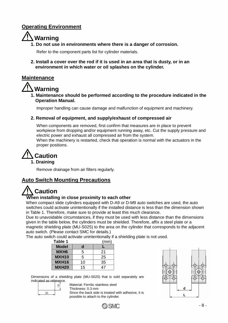
When installing in close proximity to each other When compact slide cylinders equipped with D-A9 or D-M9 auto switches are used, the auto switches could activate unintentionally if the installed distance is less than the dimension shown in Table 1. Therefore, make sure to provide at least this much clearance. Due to unavoidable circumstances, if they must be used with less distance than the dimensions given in the table below, the cylinders must be shielded. Therefore, affix a steel plate or a magnetic shielding plate (MU-S025) to the area on the cylinder that corresponds to the adjacent auto switch. (Please contact SMC for details.) The auto switch could activate unintentionally if a shielding plate is not used.
Table 1 (mm)
Model d L
MXH6 5 21
MXH10 5 25
MXH16 10 35
MXH20 15 47
Dimensions of a shielding plate (MU-S025) that is sold separately are indicated as reference.
Material: Ferritic stainless steel Thickness: 0.3 mm Since the back side is treated with adhesive, it is possible to attach to the cylinder.

- 9 -
Operating Precautions
Warning If an operator smokes after directly handling the grease used in the cylinder, it can generate hazardous gases which will harm the human body. Handle this grease with care.
Caution
1. Do not place your fingers in the clearance between the non-rotating plate and the cylinder tube.
Your fingers could get caught between the table and the cylinder tube when the piston rod retracts. If fingers are caught in a cylinder, there is a danger of injury due to the strong cylinder output, and therefore caution must be exercised.
2. In terms of the work load and moment, operate the cylinder below the
maximum work load and allowable moment. 3. If the output of the compact slide is applied directly to the table, make sure it is
applied along the rod axial line. (Refer to the figure below.)
4. Make sure to connect a speed controller and adjust it to a speed of 500 mm/s or less and to lower than the allowable kinetic energy to operate the cylinder.
5. Vibration of the workpiece due to cylinder operation
If the vibration of the workpiece due to cylinder operation is clearly noticeable, please recheck the operating conditions. Even when the moment applied to the product is under the allowable moment, the vibration width may be increased if a large amount of unbalanced load is applied.

- 10 -
Caution
Operating direction with different pressure ports The compact slide can be mounted in three directions. Check the pressure port and the operating direction. (Refer to the figure below.)
Caution
Backlash in the stroke direction Since the connection between the piston rod and table has a floating construction, the table has a backlash of less than 0.15 mm in the stroke direction. (Refer to the Fig. shown below)
(On both sides)
OUT port
IN port
OUT port
Up to 0.15 mm
IN port
Piston rod
Table
Connecting part of piston rod and table
(On both sides)
- 11 -
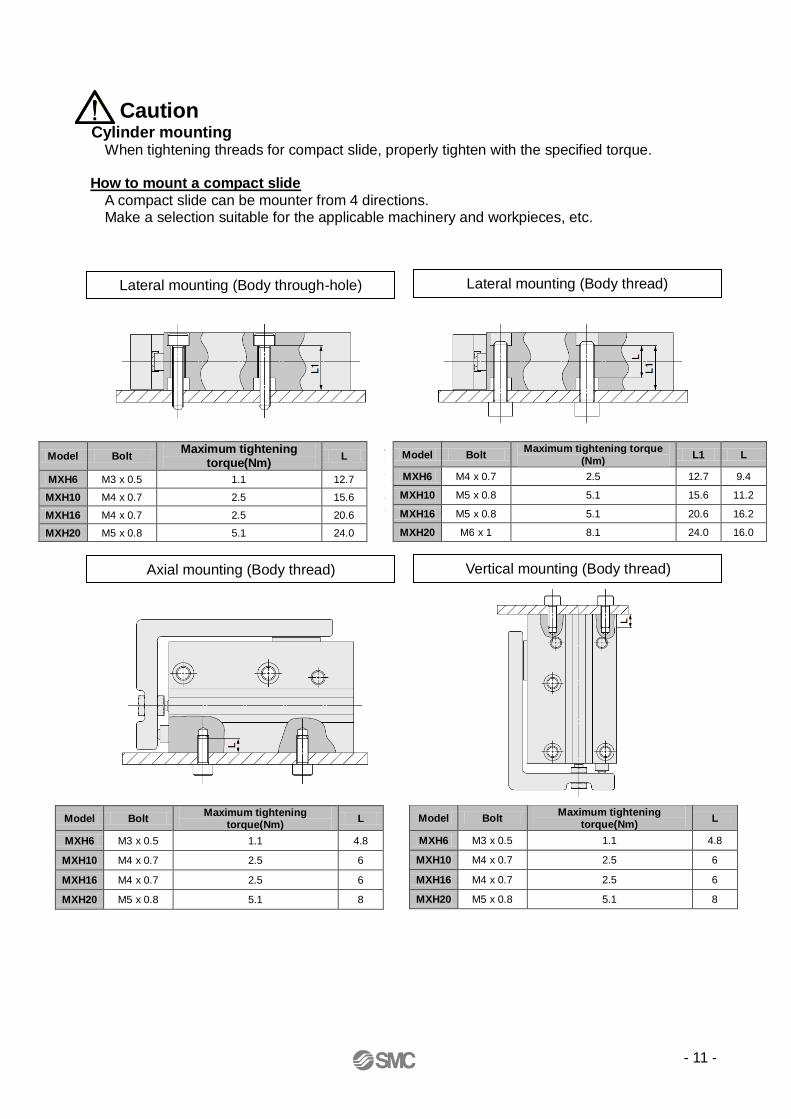
Caution
Cylinder mounting When tightening threads for compact slide, properly tighten with the specified torque.
How to mount a compact slide
A compact slide can be mounter from 4 directions. Make a selection suitable for the applicable machinery and workpieces, etc.
Lateral mounting (Body through-hole) Lateral mounting (Body thread)
Vertical mounting (Body thread) Axial mounting (Body thread)
Model Bolt Maximum tightening torque
(Nm) L1 L
MXH6 M4 x 0.7 2.5 12.7 9.4
MXH10 M5 x 0.8 5.1 15.6 11.2
MXH16 M5 x 0.8 5.1 20.6 16.2
MXH20 M6 x 1 8.1 24.0 16.0
Model Bolt Maximum tightening
torque(Nm) L
MXH6 M3 x 0.5 1.1 12.7
MXH10 M4 x 0.7 2.5 15.6
MXH16 M4 x 0.7 2.5 20.6
MXH20 M5 x 0.8 5.1 24.0
Model Bolt Maximum tightening
torque(Nm) L
MXH6 M3 x 0.5 1.1 4.8
MXH10 M4 x 0.7 2.5 6
MXH16 M4 x 0.7 2.5 6
MXH20 M5 x 0.8 5.1 8
Model Bolt Maximum tightening
torque(Nm) L
MXH6 M3 x 0.5 1.1 4.8
MXH10 M4 x 0.7 2.5 6
MXH16 M4 x 0.7 2.5 6
MXH20 M5 x 0.8 5.1 8

- 12 -
Caution
Workpiece mounting When mounting a workpiece on the top of the table, do not screw a bolt in more deeper than the L dimension shown in the table below. If screwing a bolt in more deeper than the L dimension, the edge of the bolt could reach the linear guide and might damage the linear guide.
How to mount a workpiece Workpiece can be mounted on 2 surfaces of the compact slide.
(1) Since the table is supported by the linear guide, take care not to apply strong impact or large
moment, etc. when mounting workpieces. (2) Hold the table when fastening workpiece to it with bolts etc.
If the body is held while tightening bolts etc., the guide section will be subjected to a large moment, and there many be a loss of precision.
(3) For connection with a load having an external support/guide mechanism, select an appropriate connection method and perform careful alignment.
(4) Use caution, as scratches or nicks, etc. on the sliding parts of the piston rod can cause a malfunction and air leakage.
(5) Please consult with SMC when mounting a workpiece from the rear surface of the table with bolts.
Front mounting Top mounting
(Rear surface of the table)
Model Bolt Maximum tightening
torque(Nm) L
MXH6 M3 x 0.5 1.1 5.5
MXH10 M4 x 0.7 2.5 7.5
MXH16 M4 x 0.7 2.5 10
MXH20 M5 x 0.8 5.1 11
Model Bolt Maximum tightening
torque(Nm) L
MXH6 M3 x 0.5 1.1 6.5
MXH10 M4 x 0.7 2.5 8
MXH16 M4 x 0.7 2.5 9
MXH20 M5 x 0.8 5.1 9.5

- 13 -
1. Model Indication and How to Order
Standard stroke
チューブ内径 標準ストローク6,10,16,20 5,10,15,20,25,30,40,50,60
Applicable auto switches
Number of auto switches
Nil 2 pcs.
S 1 pc.
Auto switch
6 6 mm Nil
10 10 mm
16 16 mm
20 20 mm
Bore size
Without auto switch (Built-in magnet)
Made-to-order
Compact Slide
Cylinder stroke (mm) Refer to "Standard stroke" table.
MXH 10 60 M9BW - - - Z
* Water resistant type auto switches can be mounted on the above models, but in such case SMC cannot guarantee water resistance. Please consult with SMC regarding water resistant types with the above model numbers.
* Lead wire length symbols 0.5 m・・・Nil (Example) M9NW
1 m・・・M (Example) M9NWM
3 m・・・L (Example) M*NWL
5 m・・・Z (Example) M9NWZ
* Solid state auto switches marked with "○" are produced upon receipt of order.
AC 縦取出し 横取出し 0.5(無記号)
1(M)
3(L)
5(Z)
3線(NPN)
M9NV M9N ● ● ● ○ ○
3線(PNP)
M9PV M9P ● ● ● ○ ○
2線 12V M9BV M9B ● ● ● ○ ○ ―
3線(NPN)
M9NWV M9NW ● ● ● ○ ○
3線(PNP)
M9PWV M9PW ● ● ● ○ ○
2線 12V M9BWV M9BW ● ● ● ○ ○ ―
3線(NPN)
※※M9NAV
※※M9NA ○ ○ ● ○ ○
3線(PNP)
※※M9PAV
※※M9PA ○ ○ ● ○ ○
2線 12V ※※M9BAV
※※M9BA ○ ○ ● ○ ○ ―
3線(NPN相当)
― 5V ― A96V A96 ● ― ● ― ―IC
回路―
100V A93V A93 ● ― ● ● ― ―
無100V以下
A90V A90 ● ― ● ― ―IC
回路
種類 特殊機能リード線取出し
表示灯配線
(出力)
負荷電圧
DC
リード線長さ(m)プリワイヤコネクタ
適用負荷オートスイッチ品番
2線
24V
5V12V
5V12V
5V12V
12V24V
有
有グロメット
グロメット
無接点オー
トスイ
ッチ
有接点
オー
ト
スイ
ッチ
IC回路
IC回路
IC回路
―
診断表示(2色表示)
耐水性向上品
(2色表示)
―
―リレーPLC
リレーPLC
Bore size (mm) Standard stroke (mm)
6, 10, 16, 20 5, 10, 15, 20, 25, 30, 40, 50, 60
Type Special
function
Electrical
entry Indicator
light
Wiring
(Output)
Load voltage Auto switch model Lead wire length (m) Pre-wired
connector
Applicable
load DC AC Perpendicular In-line 0.5
(Nil)
1
(M)
3
(L)
5
(Z)
Solid
sta
te a
uto
sw
itch
-
Grommet Yes
3-wire (NPN)
24 V
5 V 12V
-
M9NV M9N ● ● ● ○ ○ IC
circuit
Relay, PLC
3-wire
(PNP) M9PV M9P ● ● ● ○ ○
2-wire 12 V M9BV M9B ● ● ● ○ ○ -
Diagnostic indication (2-color
indication)
3-wire (NPN) 5 V
12 V
M9NWV M9NW ● ● ● ○ ○ IC
circuit 3-wire
(PNP) M9PWV M9PW ● ● ● ○ ○
2-wire 12 V M9BWV M9BW ● ● ● ○ ○ -
Water resistant (2-color
indication)
3-wire
(NPN) 5 V 12 V
**M9NAV **M9NA ○ ○ ● ○ ○ IC
circuit 3-wire (NPN)
**M9PAV **M9PA ○ ○ ● ○ ○
2-wire 12 V **M9BAV **M9BA ○ ○ ● ○ ○ -
Ree
d s
witch
- Grommet
Yes
3-wire
(NPN equivalent)
- 5 V - A96V A96 ● - ● - - IC
circuit -
2-wire 24 V
12 V
100 V A93V A93 ● - ● ● - -
Relay,
PLC No 100 V
or less
A90V A90 ● - ● - - IC
circuit

- 14 -
2. Names of Parts
番号 部品名 材質 備考1 シリンダチューブ アルミニウム合金 硬質アルマイト2 ロッドカバー アルミニウム合金 硬質アルマイト3 ピストンロッド ステンレス鋼4 ガイド 主部品はステンレス鋼5 テーブル アルミニウム合金 硬質アルマイト6 ピストン アルミニウム合金 クロメート7 マグネット 磁石材8 鋼球 炭素鋼9 ダンパ ウレタン
10 ダンパ ウレタン11 皿小ねじ 炭素鋼 ニッケルめっき12 ナット 黄銅 ニッケルめっき13 ロッドパッキン NBR14 ピストンパッキン NBR15 ガスケット NBR16 プラグ 炭素鋼 亜鉛クロメート
注)MXH-Zシリーズは分解できません。
構成部品
Component Parts
No. Description Material Note
1 Cylinder tube Aluminum alloy Hard anodized
2 Rod cover Aluminum alloy Hard anodized
3 Piston rod Stainless steel
4 Guide The main parts are made from stainless steel.
5 Table Aluminum alloy Hard anodized
6 Piston Aluminum alloy Chromated
7 Magnet Magnetic material
8 Steel ball Carbon steel
9 Bumper Urethane
10 Bumper Urethane
11 Screw Carbon steel Nickel plated
12 Nut Brass Nickel plated
13 Rod seal NBR
14 Piston seal NBR
15 Gasket NBR
16 Plug Carbon steel Zinc chromated
*) MXH-Z series cannot be disassembled.

- 15 -
3. Specifications
Theoretical output
チューブ内径(mm) 6 10 16 20
使用流体
作動方式
配管接続口径
最低使用圧力 0.15MPa 0.05MPa
最高使用圧力
保証耐圧力
周囲温度および使用流体温度
使用ピストン速度
許容運動エネルギー [J] 0.0125 0.025 0.05 0.1
給油
クッション
ストローク長さの許容差
オートスイッチ(オプション)
無接点オートスイッチD-M9□,M9□W型有接点オートスイッチD-A9□型
空気
複動形
M5X0.8
両側ラバークッション
無給油
+1.00
50~500mm/s
0.06MPa
0.7MPa
1.05MPa
オートスイッチなし:-10~70℃(ただし、凍結なきこと)オートスイッチ付 :-10~60℃(ただし、凍結なきこと)
Bore size (mm) 6 10 16 20 Fluid Air
Action Double acting
Piping port size M5 x 0.8
Minimum operating pressure 0.15 MPa 0.06 MPa 0.05 MPa
Maximum operating pressure 0.7 MPa
Proof pressure 1.05 MPa
Ambient and fluid temperature Without auto switch: -10 to 70oC (No freezing)
With auto switch: -10 to 60oC (No freezing)
Piston speed 50 to 500 mm/s
Allowable kinetic energy (J) 0.0125 0.025 0.05 0.1
Lubrication Non-lube
Cushion Rubber bumper on both ends
Stroke length tolerance +1.0
0
Auto switch (Option)
Solid state auto switch D-M9[], M9[]W Reed switch D-A9[]
Bore size (mm)
Rod size (mm)
Operating direction Pistonrea
(mm2)
Operating pressure (MPa)
0.3 0.5 0.7
6 3 OUT 28 8 14 19
IN 21 6 10 14
10 4 OUT 78 23 39 55
IN 66 19 33 46
16 6 OUT 201 60 101 141
IN 172 51 86 121
20 8 OUT 314 94 157 220
IN 264 79 132 185

- 16 -
4. Model Selection
Caution Confirmation of theoretical output is required separately. Refer to "Theoretical
Output" on page 15.
Selection Conditions: Follow the tables below in order to determine selection conditions
and choose one selection graph.
* L: Overhang The distance from the cylinder shaft center to the load center of gravity.
The direction of L can also be a diagonal direction. (Refer to the drawing at right.)
* H: The distance from the cylinder shaft center to the table mounting surface.
Mounting orientation
Load eccentricity L1 Selection graph
L1: Load
eccentricity
Load center of gravity
Cylinder shaft center
Selection graph (1) to (3) (Vertical
mounting)
Graph (1) Maximum speed 100 (mm/s) or less Graph (3) Maximum speed 500 (mm/s) or less
Graph (2) Maximum speed 300 (mm/s) or less
Overhang L (mm)
Overhang L (mm)
Overhang L (mm)
We
ight m
(kg)
We
ight m
(kg)
We
ight m
(kg)
Selection example (Vertical mounting) (1) Selection conditions Mounting: Vertical Maximum speed: 500 mm/s Overhang: 40 mm Load mass: 0.1 kg
Refer to Graph (3) based on vertical mounting and a speed of 500 mm/s. In Graph (3), find the intersection of a 40 mm overhang and load mass of 0.1 kg, which results in a determination of φ16.
Horizontal
Maximumspeed(mm/s)
Vertical
MXH6 MXH10 MXH16 MXH20
H dimension (mm) 24.5 30.5 34.5 41.5

- 17 -
Selection graph (4) to (12) (Horizontal mounting)
Maximum speed 100 (mm/s) or less Maximum speed 300 (mm/s) or less Maximum speed 500 (mm/s) or less
Graph (4) Load eccentricity 50 mm Graph (7) Load eccentricity 50 mm Graph (10) Load eccentricity 50 mm
Graph (5) Load eccentricity 100mm Graph (8) Load eccentricity 100mm Graph (11) Load eccentricity 100mm
Graph (6) Load eccentricity 200mm
Graph (9) Load eccentricity 200mm
Graph (12) Load eccentricity 200mm
We
ight
m
(kg)
Overhang L (mm)
Overhang L (mm)
Overhang L (mm)
We
ight
m
(kg)
We
ight
m
(kg)
Overhang L (mm)
We
ight
m
(kg)
Overhang L (mm)
Overhang L (mm)
We
ight
m
(kg)
We
ight
m
(kg)
Overhang L (mm)
Overhang L (mm)
Overhang L (mm)
We
ight
m
(kg)
We
ight
m
(kg)
We
ight
m
(kg)
Graph (6) Load eccentricity 200mm Graph (9) Load eccentricity 200mm Graph (12) Load eccentricity 200mm
Selection example (Horizontal mounting) (2) Selection conditions Mounting: Horizontal Maximum speed: 500 mm/s Load eccentricity: 50 mm
Overhang: 30 mm Load mass: 0.1 kg
Refer to Graph (10) based on horizontal mounting, a speed of 500 mm/s and load eccentricity of 50 mm. In Graph (10), find the intersection of a 30 mm overhang and load mass of 0.1 kg, which results in a determination of φ10.

- 18 -
5. Auto Switch Mounting
● Minimum stroke for auto switch mounting
● Auto switch proper mounting position (detection at stroke end) and its mounting height
Note 1: Negative figures in the table W indicate an auto switch is mounted inward from the edge of the cylinder body.
Note 2: In the case of models with 5 and 10 strokes, the switch may not turn off due to operating range or two switches may
turn on simultaneously.
Fix switches outside 1 to 4 mm further than the values in the above table. (If one switch is used, make sure that it
turns ON and OFF properly; if two switches are used, make sure that both switches turn ON.)
Note 3: ( ) in column W denotes the dimensions of D-A90/A93.
D-A9□D-A9□V
D-M9□D-M9□V
D-M9□WD-M9□WV
D-M9□AD-M9□AV
1ヶ付 5 5 5 5
2ヶ付 10 5 10 10
オートスイッチ取付数
適用オートスイッチ型式
A W B A W B A W B A W B A W B
6 12.5 3.5(6) ― 16.5 7.5 2.5 16.5 5.5 2.5 16.5 9.5 2.5 16.5 7.5 2.5
10 11.0 -2.0(0.5) 3.5 15.0 2.0 7.5 15.0 0 7.5 15.0 4.0 7.5 15.0 2.0 7.5
16 18.0 -2.0(0.5) 4.0 22.0 2.0 8.0 22.0 0 8.0 22.0 4.0 8.0 22.0 2.0 8.0
20 26.0 -4.5(-2) 6.5 30.0 -0.5 10.5 30.0 -2.5 10.5 30.0 1.5 10.5 30.0 -0.5 10.5
D-M9□W・D-M9□ D-M9□WV・D-M9□V D-M9□A D-M9□AVチューブ内径(mm)
D-A9□・D-A9□V
D-M9[] D-M9[]W D-M9[]A D-M9[]
D-M9[]V D-M9[]WV D-M9[]AV D-M9[]V
[ ]: denotes the values of D-M9[]A. ( ): denotes the values of D-90/A93.
( ): denotes the values of D-M9[]AV/A9[]V.
Number of auto switches mounted
Applicable auto switch model
D-A9[] D-A9[]V
D-M9[] D-M9[]V
D-M9[]W D-M9[]WV
D-M9[]A D-MP[]AV
1 pc. 5 5 5 5
2 pcs. 10 5 10 10
Bore size (mm)
D-A9[], D-A9[]V D-M9[]W, D-M9[] D-M9[]WV, D-M9[]V D-M9[]A D-M9[]AV
A W B A W B A W B A W B A W B
6 12.5 3.5 (6) - 16.5 7.5 2.5 16.5 5.5 2.5 16.5 9.5 2.5 16.5 7.5 2.5
10 11 -2.0 (0.5) 3.5 15.0 2.0 7.5 15.0 0 7.5 15.0 4.0 7.5 15.0 2.0 7.5
16 18 -2.0 (0.5) 4 22.0 2.0 8.0 22.0 0 8.0 22.0 4.0 8.0 22.0 2.0 8.0
20 26 -4.5 (-2) 6.5 30.0 -0.5 10.5 30.0 -2.5 10.5 30.0 1.5 10.5 30.0 -0.5 10.5
- 19 -
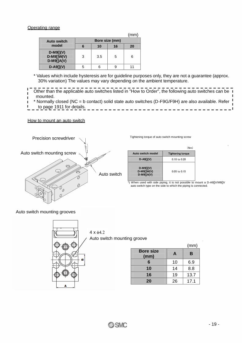
Operating range
How to mount an auto switch
(N・m)オートスイッチ型式 締付トルク
D-A9□(V) 0.10~0.20D-M9□(V)
D-M9□W(V)D-M9□A(V)
0.05~0.15
●オートスイッチ取付ビスを締付ける際には、 握り径5~6mmの時計ドライバを使用して下さい。
オートスイッチ取付ビスの締付トルク
注)側面配管でご使用の場合、配管面にオートスイッチ D-A9□V型、M9□V型は取付けられませんので ご注意ください。
(mm)チューブ内径(mm) A B
6 10 6.910 14 8.816 19 13.720 26 17.1
(mm)
6 10 16 20D-M9□(V)
D-M9□W(V)D-M9□A(V)
3 3.5 5 6
D-A9□(V) 5 6 9 11
オートスイッチ型式チューブ内径(mm)
4 x
Auto switch mounting groove
Auto switch mounting grooves
Precision screwdriver
Auto switch mounting screw
Auto switch
* Values which include hysteresis are for guideline purposes only, they are not a guarantee (approx. 30% variation) The values may vary depending on the ambient temperature.
Other than the applicable auto switches listed in "How to Order", the following auto switches can be mounted.
* Normally closed (NC = b contact) solid state auto switches (D-F9G/F9H) are also available. Refer
to page 1911 for details.
(mm)
Auto switch model
Bore size (mm)
6 10 16 20
D-M9[](V) D-M9[]W(V) D-M9[]A(V)
3 3.5 5 6
D-A9[](V) 5 6 9 11
Tightening torque of auto switch mounting screw
(Nm)
Auto switch model Tightening torque
D-A9[](V) 0.10 to 0.20
D-M9[](V) D-M9[]W(V) D-M9[]A(V)
0.05 to 0.15
*) When used with side piping, it is not possible to mount a D-A9[]V/M9[]V auto switch type on the side to which the piping is connected.
(mm)
Bore size (mm)
A B
6 10 6.9
10 14 8.8
16 19 13.7
20 26 17.1
- 20 -
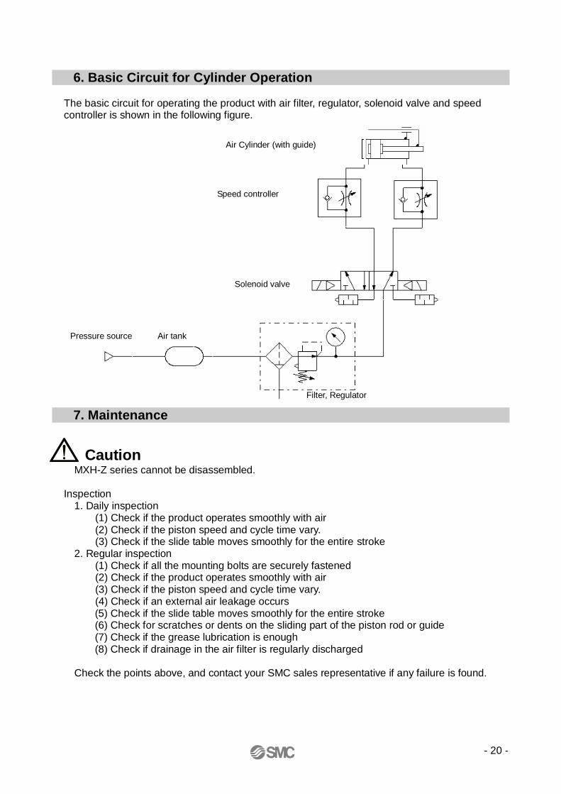
6. Basic Circuit for Cylinder Operation The basic circuit for operating the product with air filter, regulator, solenoid valve and speed controller is shown in the following figure.
7. Maintenance
Caution MXH-Z series cannot be disassembled.
Inspection 1. Daily inspection (1) Check if the product operates smoothly with air (2) Check if the piston speed and cycle time vary. (3) Check if the slide table moves smoothly for the entire stroke 2. Regular inspection (1) Check if all the mounting bolts are securely fastened (2) Check if the product operates smoothly with air (3) Check if the piston speed and cycle time vary. (4) Check if an external air leakage occurs
(5) Check if the slide table moves smoothly for the entire stroke (6) Check for scratches or dents on the sliding part of the piston rod or guide (7) Check if the grease lubrication is enough (8) Check if drainage in the air filter is regularly discharged
Check the points above, and contact your SMC sales representative if any failure is found.
Air Cylinder (with guide)
Speed controller
Solenoid valve
Filter, Regulator
Air tank Pressure source

- 21 -
8. Troubleshooting
Failure Possible causes
Countermeasures Remarks
The product does not operate
smoothly.
The cylinder speed is outside of the specification range.
- Use the products within the specified cylinder speed range.
- Review the bore size of the cylinder tube.
Refer to "4. Model Selection".
The moment of the cylinder is above the allowable range.
- Change the moment to be within the allowable range.
- Review the bore size of the cylinder tube.
Refer to "4. Model Selection".
Speed controller is meter-in control.
- Change it to meter-out control.
Vibration is generated.
- Install the product in a place where it is not subjected to vibration.
- Avoid applying external forces to the product.
- Check the load eccentricity.
Even when the moment applied to the product is under the allowable moment, the vibration width may be increased if a large amount of load eccentricity is applied.
Water or coolant liquid, splash over
the product.
- Protect the cylinder with a cover to avoid liquid splash.
The operation is not checked with air.
- Check the operation of the product by supplying air, not by hand.
If resistance is generated due to preload of the guide, the product may not be operated smoothly by hand, but there is no problem on performance.
Deformation or breakage
Impact applied due to high speed
operation
- Reduce the cylinder speed to be within the allowable specification range.
- Reduce the load. Refer to "4. Model Selection".
- Install an external impact absorbing mechanism.
Auto switch does not operate.
(Malfunction)
The auto switch is not mounted in the proper mounting
position.
- Mount the auto switch in a proper position.
Refer to "5. Auto Switch Mounting".
Multiple cylinders are mounted
horizontally in close proximity.
- When mounting the cylinders, ensurethe specified distance for closeproximity installation is met.
- Affix a magnetic shielding plate (MU-S025) to the area on the cylinder that corresponds to the adjacent auto switch.
Refer to "Caution on Mounting Auto Switches".
(When installing in close proximity to each other)
* The guide has significant rolling resistance from the preload of the ball bearings. A feeling of grinding is felt when it is operated by hand, but there is no problem with performance.

- 22 -
Revision history
4-14-1, Sotokanda, Chiyoda-ku, Tokyo 101-0021 JAPAN Tel: + 81 3 5207 8249 Fax: +81 3 5298 5362 URL http://www.smcworld.com
Note) This manual is subject to change without prior notice.
© 2012 SMC Corporation All Rights Reserved