Embed Size (px)
Citation preview
1
IMPORTANTInstaller: This Manual is the property of the customer and
must be retained with the product formaintenance and operational purposes.
320 cPRODUCT MANUAL
2
INDEXPage
INTRODUCTION 3DESCRIPTION 3SAFETY : WARNINGS 3SPECIFICATION
Important Points 4Normal Operating Conditions 4Operating Parameters 4
- Pressures/Flow Rates 4- Temperatures 5- Connections 5- Standard Inlet Configuration 6- Flow Control 6
DIMENSIONS 6PACK CONTENTS 7INSTALLATION
General 8Outlet position/Reversed inlets 8Installation 9
COMMISSIONINGMaximum Temperature 11Maximum Temperature Setting 11
- For Adjustable Temperature 11- For Locked Temperature 12
Commissioning Checks 13OPERATION 13FAULT DIAGNOSIS 14MAINTENANCE
General 16Planned Maintenance Programmes 16
(Preventative/Precautionary Maintenance)Maintenance Procedures 17
- Lubricants 17- Cartridge Assembly 17- Check Valve Cartridges 19- Inlet Filters 21
SPARE PARTS 22CUSTOMER CARE Back Cover
3
WARNING! Continued use of this product in conditions outside the limits listed inthis section can severely affect the performance and reduce the effective service life,and can present potential risk to users.
Rada products are precision-engineered and should give continued superior andsafe performance, provided:
1. They are installed, commissioned, operated and maintained in accordance withthe recommendations given in this Manual.
2. Periodic attention is given, as necessary, to maintain the product in goodfunctional order. Recommended guidelines are given in the MAINTENANCEsection.
The function of a thermostatic mixing valve is to deliver water consistently at a safetemperature.
In keeping with every other mechanism, it cannot be considered as being functionallyinfallible and as such, cannot totally replace the vigilance of nursing/supervisorystaff where that is necessary.
Provided it is installed, commissioned, operated and maintained within theserecommendations, the risk of failure, if not eliminated, is reduced to the minimumachievable.
SAFETY : WARNINGS
INTRODUCTIONRada Thermoscopic mixing valves are specified to meet the highest standards ofsafety, comfort and economy as demanded by todays users. All Rada products aredesigned, manufactured and supported in accordance with accredited BS EN ISO9001:1994 Quality Systems.
This Manual covers the Rada 320 c valve manufactured from May 1998.
A 3/4" thermostatic mixing valve to suit a wide diversity of applications and installationformats.
Incorporates the Radatherm cartridge, a unique sealed-for-life unit utilising provendurability high-technology materials for extended service-free reliability. This cartridgeemploys the advanced 2nd generation 'thermoscopic' temperature sensor to providewater at safe, accurate temperatures for showering or process requirements.
The mixing valve inlets incorporate integral isolating valves, strainers and checkvalves.
For connection to surface pipework, includes angled checkvalve elbows withintegral isolating ball valve. Supplied with compression type connections.
DESCRIPTION
4
SPECIFICATIONImportant Points:1 The installation, commissioning and maintenance of this product must be carried
out in accordance with instructions given in this Manual, and must be conductedby designated, qualified and competent personnel.
2. Installations must comply with all Local/National Water Supply AuthorityRegulations/Byelaws, and Building and Plumbing (UK: BS6700) Regulations.
3. Rada products are precision-engineered and should give continued superior andsafe performance, provided:-
- they are installed, commissioned, operated and maintained in accordance withthese recommendations
- periodic attention is given as necessary to maintain the product in good functionalorder. Recommended guidelines are given in the MAINTENANCE section.
4. WARNING! Continued use of this product in conditions outside the limits listedin this section can severely affect the performance and reduce the effectiveservice life, and can present potential risk to users.
5. Disinfectants: In applications where system chemical disinfection is practised,chlorine can be used (calculated chlorine concentration of 50mg/l (ppm) maximumin water, per one hour dwell time, at service interval frequency). Such proceduresmust be conducted strictly in accordance with the information supplied with thedisinfectant and with all relevant Guidelines/Approved Codes of Practice.
If in any doubt as to the suitability of chemical solutions, refer to Kohler Mira Ltd,or Local Agent.
Normal Operating Conditions are considered as:
- inlet dynamic pressures nominally balanced to within 10% of each other duringflow.
- a differential of approximately 50oC between the hot and cold inlet temperatures,and with differentials of 15-35oC between the blend setting and either supply.
- daily usage of 1 - 6 hours.- installation and usage environment not subject to extremes of temperature,
unauthorised tampering or wilful abuse.
Operating ParametersPressures/Flow RatesFor optimum performance, dynamic supply pressures should be nominally equal.
5
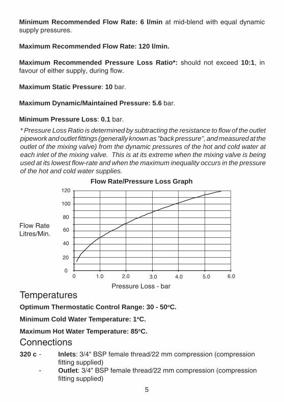
Minimum Recommended Flow Rate: 6 l/min at mid-blend with equal dynamicsupply pressures.
Maximum Recommended Flow Rate: 120 l/min.
Maximum Recommended Pressure Loss Ratio*: should not exceed 10:1, infavour of either supply, during flow.
Maximum Static Pressure: 10 bar.
Maximum Dynamic/Maintained Pressure: 5.6 bar.
Minimum Pressure Loss: 0.1 bar.
Flow Rate/Pressure Loss Graph
TemperaturesOptimum Thermostatic Control Range: 30 - 50oC.
Minimum Cold Water Temperature: 1oC.
Maximum Hot Water Temperature: 85oC.
Connections320 c - Inlets: 3/4" BSP female thread/22 mm compression (compression
fitting supplied)- Outlet: 3/4" BSP female thread/22 mm compression (compression
fitting supplied)
Flow RateLitres/Min.
Pressure Loss - bar
80
0 1.0 3.0 4.02.0
60
40
0
100
120
6.05.0
20
* Pressure Loss Ratio is determined by subtracting the resistance to flow of the outletpipework and outlet fittings (generally known as "back pressure", and measured at theoutlet of the mixing valve) from the dynamic pressures of the hot and cold water ateach inlet of the mixing valve. This is at its extreme when the mixing valve is beingused at its lowest flow-rate and when the maximum inequality occurs in the pressureof the hot and cold water supplies.
6
Standard Inlet Configurationhot - left (marked red)
cold - right (marked blue)
Flow ControlRada 320 c mixing valves do not have integral flow control; appropriate provisionmust be made for this in the outlet pipework.
This can be in the form of stop-cock, mechanical timed-flow controller or solenoid.
The device chosen must be non-concussive in operation.
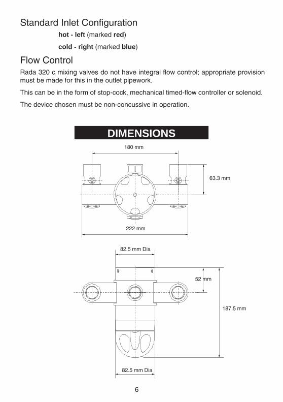
DIMENSIONS180 mm
63.3 mm
222 mm
82.5 mm Dia
187.5 mm
52 mm
82.5 mm Dia
7
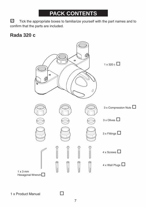
PACK CONTENTS� Tick the appropriate boxes to familiarize yourself with the part names and toconfirm that the parts are included.
Rada 320 c
1 x 320 c �
1 x 3 mmHexagonal Wrench
3 x Olives �
3 x Compression Nuts �
1 x Product Manual �
4 x Screws �
3 x Fittings �
�
4 x Wall Plugs �
�
8
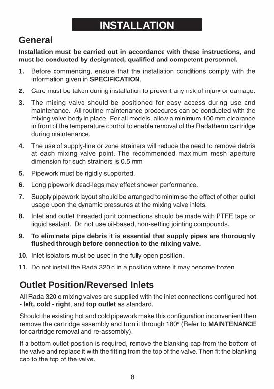
INSTALLATIONGeneralInstallation must be carried out in accordance with these instructions, andmust be conducted by designated, qualified and competent personnel.
1. Before commencing, ensure that the installation conditions comply with theinformation given in SPECIFICATION.
2. Care must be taken during installation to prevent any risk of injury or damage.
3. The mixing valve should be positioned for easy access during use andmaintenance. All routine maintenance procedures can be conducted with themixing valve body in place. For all models, allow a minimum 100 mm clearancein front of the temperature control to enable removal of the Radatherm cartridgeduring maintenance.
4. The use of supply-line or zone strainers will reduce the need to remove debrisat each mixing valve point. The recommended maximum mesh aperturedimension for such strainers is 0.5 mm
5. Pipework must be rigidly supported.
6. Long pipework dead-legs may effect shower performance.
7. Supply pipework layout should be arranged to minimise the effect of other outletusage upon the dynamic pressures at the mixing valve inlets.
8. Inlet and outlet threaded joint connections should be made with PTFE tape orliquid sealant. Do not use oil-based, non-setting jointing compounds.
9. To eliminate pipe debris it is essential that supply pipes are thoroughlyflushed through before connection to the mixing valve.
10. Inlet isolators must be used in the fully open position.
11. Do not install the Rada 320 c in a position where it may become frozen.
Outlet Position/Reversed InletsAll Rada 320 c mixing valves are supplied with the inlet connections configured hot- left, cold - right, and top outlet as standard.
Should the existing hot and cold pipework make this configuration inconvenient thenremove the cartridge assembly and turn it through 180o (Refer to MAINTENANCEfor cartridge removal and re-assembly).
If a bottom outlet position is required, remove the blanking cap from the bottom ofthe valve and replace it with the fitting from the top of the valve. Then fit the blankingcap to the top of the valve.
9
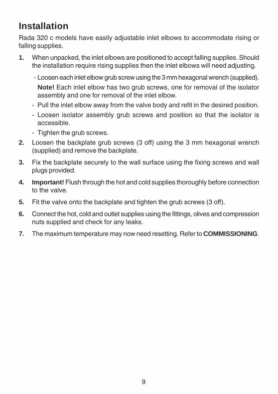
InstallationRada 320 c models have easily adjustable inlet elbows to accommodate rising orfalling supplies.
1. When unpacked, the inlet elbows are positioned to accept falling supplies. Shouldthe installation require rising supplies then the inlet elbows will need adjusting.
- Loosen each inlet elbow grub screw using the 3 mm hexagonal wrench (supplied).
Note! Each inlet elbow has two grub screws, one for removal of the isolatorassembly and one for removal of the inlet elbow.
- Pull the inlet elbow away from the valve body and refit in the desired position.
- Loosen isolator assembly grub screws and position so that the isolator isaccessible.
- Tighten the grub screws.
2. Loosen the backplate grub screws (3 off) using the 3 mm hexagonal wrench(supplied) and remove the backplate.
3. Fix the backplate securely to the wall surface using the fixing screws and wallplugs provided.
4. Important! Flush through the hot and cold supplies thoroughly before connectionto the valve.
5. Fit the valve onto the backplate and tighten the grub screws (3 off).
6. Connect the hot, cold and outlet supplies using the fittings, olives and compressionnuts supplied and check for any leaks.
7. The maximum temperature may now need resetting. Refer to COMMISSIONING.
10
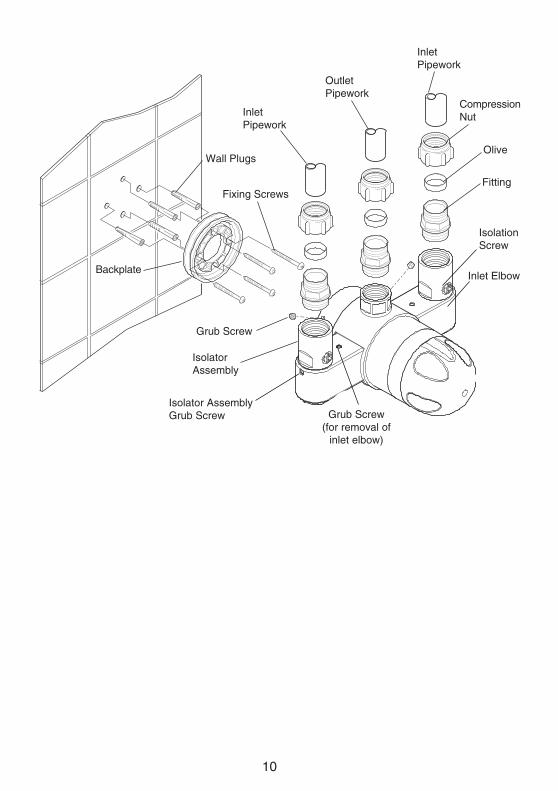
Backplate
IsolationScrew
IsolatorAssembly
CompressionNut
OliveWall Plugs
Fixing Screws
Grub Screw
Fitting
InletPipework
InletPipework
OutletPipework
Inlet Elbow
Grub Screw(for removal of
inlet elbow)
Isolator AssemblyGrub Screw
11
COMMISSIONING
Commissioning must be carried out in accordance with these instructions,and must be conducted by designated, qualified and competent personnel.
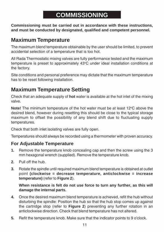
Maximum TemperatureThe maximum blend temperature obtainable by the user should be limited, to preventaccidental selection of a temperature that is too hot.
All Rada Thermostatic mixing valves are fully performance tested and the maximumtemperature is preset to approximately 43oC under ideal installation conditions atthe factory.
Site conditions and personal preference may dictate that the maximum temperaturehas to be reset following installation.
Maximum Temperature SettingCheck that an adequate supply of hot water is available at the hot inlet of the mixingvalve.
Note! The minimum temperature of the hot water must be at least 12oC above thedesired blend, however during resetting this should be close to the typical storagemaximum to offset the possibility of any blend shift due to fluctuating supplytemperatures.
Check that both inlet isolating valves are fully open.
Temperatures should always be recorded using a thermometer with proven accuracy.
For Adjustable Temperature1. Remove the temperature knob concealing cap and then the screw using the 3
mm hexagonal wrench (supplied). Remove the temperature knob.
2. Pull off the hub.
3. Rotate the spindle until required maximum blend temperature is obtained at outletpoint (clockwise = decrease temperature, anticlockwise = increasetemperature) (refer to Figure 2).
When resistance is felt do not use force to turn any further, as this willdamage the internal parts.
4. Once the desired maximum blend temperature is achieved, refit the hub withoutdisturbing the spindle: Position the hub so that the hub stop comes up againstthe cartridge stop (refer to Figure 2) preventing any further rotation in ananticlockwise direction. Check that blend temperature has not altered.
5. Refit the temperature knob. Make sure that the indicator points to 9 o'clock.
12
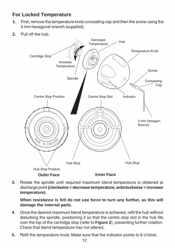
For Locked Temperature1. First, remove the temperature knob concealing cap and then the screw using the
3 mm hexagonal wrench (supplied).
2. Pull off the hub.
3. Rotate the spindle until required maximum blend temperature is obtained atdischarge point (clockwise = decrease temperature, anticlockwise = increasetemperature).
When resistance is felt do not use force to turn any further, as this willdamage the internal parts.
4. Once the desired maximum blend temperature is achieved, refit the hub withoutdisturbing the spindle, positioning it so that the centre stop slot in the hub fitsover the top of the cartridge stop (refer to Figure 2), preventing further rotation.Check that blend temperature has not altered.
5. Refit the temperature knob. Make sure that the indicator points to 6 o'clock.
Temperature Knob
Hub
Screw
3 mm HexagonWrench
Spindle
Cartridge Stop
Centre Stop SlotCentre Stop Position
Hub Stop
Hub Stop Position
Hub Stop
Inner FaceOuter Face
IncreaseTemperature
DecreaseTemperature
Indicator
ConcealingCap
13
OPERATION
For models with knob fitted for adjustable temperature control, adjustment of blendtemperature from preset maximum to cold is achieved by clockwise rotation of theknob.
For models with locked temperature control, no user adjustment is intended.
Control of flow is via separate outlet valve(s), refer Flow Control.
Commissioning Checks(Temperatures should always be recorded using a thermometer with provenaccuracy).
- Check inlet pipework temperatures for correct function of checkvalves.
- Operate the outlet flow control and check:
1. Flow rate is sufficient for purpose.
2. Temperature(s) obtainable are acceptable.
3. All connections and mixer body are water tight.
- It is advisable to establish a performance check at this time, which should benoted for future reference as part of a Planned Maintenance Programme (aMaintenance Record Card has been provided with this Manual).
The procedure should be chosen to imitate both typical and difficult operatingconditions, such as any supply pressure fluctuations that may be likely. Anideal method is to locate another outlet on the common cold water supply closeto the mixing valve (operating this outlet may cause a drop in supply pressure),and subsequently have a temporary effect on blend temperature (should be nomore than 2oC change).
Note! Causing thermal shutdown of the mixer by full closure of the cold supply maynot adequately indicate the practical capability of the mixer, nor its service condition.Consequently this is not a recommended performance check, and repeated suchtesting may ultimately affect service life.
14
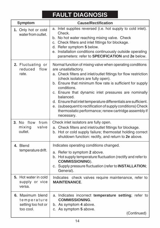
FAULT DIAGNOSISSymptom Cause/Rectification
1. Only hot or coldwater from outlet.
a. Inlet supplies reversed (i.e. hot supply to cold inlet).Check.
b. No hot water reaching mixing valve. Checkc. Check filters and inlet fittings for blockage.d. Refer symptom 5 below.e. Installation conditions continuously outside operating
parameters: refer to SPECIFICATION and 2e below.
2. Fluctuating orreduced flowrate.
3. No flow frommixing valveoutlet.
a. Check filters and inlet/outlet fittings for blockage.b. Hot or cold supply failure; thermostat holding correct
shutdown function: rectify, and return to 2e above.
4. Blendtemperature drift.
Check inlet isolators are fully open.
5. Hot water in coldsupply or viceversa.
Indicates check valves require maintenance, refer toMAINTENANCE.
6. Maximum blendt e m p e r a t u r esetting too hot ortoo cool.
a. Indicates incorrect temperature setting; refer toCOMMISSIONING.
b. As symptom 4 above.c. As symptom 5 above.
Normal function of mixing valve when operating conditionsare unsatisfactory.
Indicates operating conditions changed.
a. Refer to symptom 2 above.b. Hot supply temperature fluctuation (rectify and refer to
COMMISSIONING).c. Supply pressure fluctuation (refer to INSTALLATION;
General).
a. Check filters and inlet/outlet fittings for flow restriction(check isolators are fully open).
b. Ensure that minimum flow rate is sufficient for supplyconditions.
c. Ensure that dynamic inlet pressures are nominallybalanced.
d. Ensure that inlet temperature differentials are sufficient.e. (subsequent to rectification of supply conditions) Check
thermostatic performance; renew cartridge assembly ifnecessary.
(Continued)
15
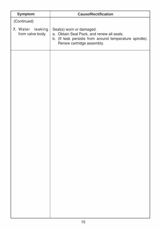
Symptom Cause/Rectification
7. Water leakingfrom valve body.
Seal(s) worn or damaged.a. Obtain Seal Pack, and renew all seals.b. (If leak persists from around temperature spindle).
Renew cartridge assembly.
(Continued)
16
MAINTENANCEGeneralRada products are precision-engineered and should give continued superior andsafe performance, provided:
1. They are installed, commissioned, operated and maintained in accordance withour recommendations.
2. Periodic attention is given as necessary to maintain the product in good functionalorder. Guidelines for frequency are given below.
All functional parts (except the temperature or locking knob) are contained withinservice-free cartridges, so any maintenance requirement is reduced to temperature,performance and functional checks and inspection, with cartridge renewal whennecessary. In larger installations with a number of mixing valves, it is good policy tomaintain a small stock of spare cartridges so that no mixing valve or facility need beout of commission for more than the time it takes to exchange the cartridge, andalso, eventually, a rolling programme of cartridge renewal can be undertaken as partof a planned maintenance procedure. The designed minimum service life of allcartridges is five years under normal operating conditions (refer to SPECIFICATION).
The use of main supply-line or zone strainers (recommended maximum meshaperture dimension is 0.5 mm) will reduce the need to remove debris at each mixingvalve point.
Rada Service Engineers/Agents will call by prior arrangement, if required. ServiceContracts may be undertaken, subject to survey - details upon request.
(Preventative/Precautionary Maintenance)The frequency and extent of attention required will vary according to prevailing siteand operational conditions however, the following guideline schedule is suggestedto cover average duty and site conditions:
Six MonthlyBlend Temperature: check for correct blend setting and/or maximum presettemperature. Reset as necessary.
Performance: check blend stability against known datum (e.g. commissioning check)for an induced pressure or flow change. Renew cartridge assembly when necessary.
Function: check inlet pipework temperature for correct function of checkvalves, andmaintain/renew as necessary. Check and clean filters as appropriate. Lubricateaccessible seals when necessary using silicone-only based lubricant.
Planned Maintenance Programmes
17
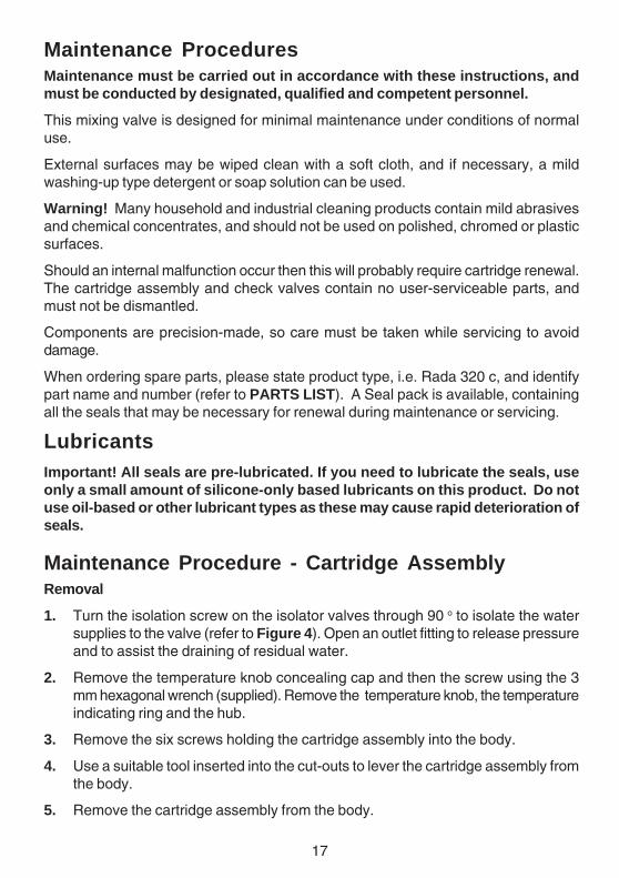
Maintenance ProceduresMaintenance must be carried out in accordance with these instructions, andmust be conducted by designated, qualified and competent personnel.
This mixing valve is designed for minimal maintenance under conditions of normaluse.
External surfaces may be wiped clean with a soft cloth, and if necessary, a mildwashing-up type detergent or soap solution can be used.
Warning! Many household and industrial cleaning products contain mild abrasivesand chemical concentrates, and should not be used on polished, chromed or plasticsurfaces.
Should an internal malfunction occur then this will probably require cartridge renewal.The cartridge assembly and check valves contain no user-serviceable parts, andmust not be dismantled.
Components are precision-made, so care must be taken while servicing to avoiddamage.
When ordering spare parts, please state product type, i.e. Rada 320 c, and identifypart name and number (refer to PARTS LIST). A Seal pack is available, containingall the seals that may be necessary for renewal during maintenance or servicing.
LubricantsImportant! All seals are pre-lubricated. If you need to lubricate the seals, useonly a small amount of silicone-only based lubricants on this product. Do notuse oil-based or other lubricant types as these may cause rapid deterioration ofseals.
Maintenance Procedure - Cartridge AssemblyRemoval
1. Turn the isolation screw on the isolator valves through 90 o to isolate the watersupplies to the valve (refer to Figure 4). Open an outlet fitting to release pressureand to assist the draining of residual water.
2. Remove the temperature knob concealing cap and then the screw using the 3mm hexagonal wrench (supplied). Remove the temperature knob, the temperatureindicating ring and the hub.
3. Remove the six screws holding the cartridge assembly into the body.
4. Use a suitable tool inserted into the cut-outs to lever the cartridge assembly fromthe body.
5. Remove the cartridge assembly from the body.
18
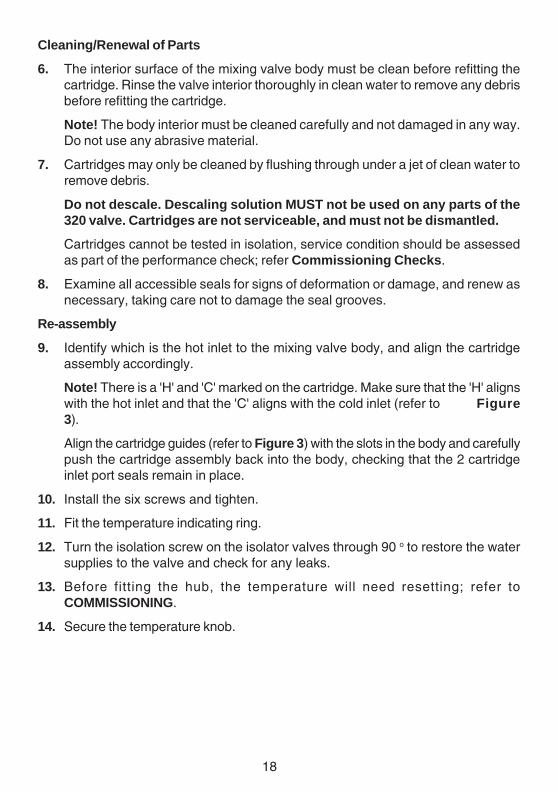
Cleaning/Renewal of Parts
6. The interior surface of the mixing valve body must be clean before refitting thecartridge. Rinse the valve interior thoroughly in clean water to remove any debrisbefore refitting the cartridge.
Note! The body interior must be cleaned carefully and not damaged in any way.Do not use any abrasive material.
7. Cartridges may only be cleaned by flushing through under a jet of clean water toremove debris.
Do not descale. Descaling solution MUST not be used on any parts of the320 valve. Cartridges are not serviceable, and must not be dismantled.
Cartridges cannot be tested in isolation, service condition should be assessedas part of the performance check; refer Commissioning Checks.
8. Examine all accessible seals for signs of deformation or damage, and renew asnecessary, taking care not to damage the seal grooves.
Re-assembly
9. Identify which is the hot inlet to the mixing valve body, and align the cartridgeassembly accordingly.
Note! There is a 'H' and 'C' marked on the cartridge. Make sure that the 'H' alignswith the hot inlet and that the 'C' aligns with the cold inlet (refer to Figure3).
Align the cartridge guides (refer to Figure 3) with the slots in the body and carefullypush the cartridge assembly back into the body, checking that the 2 cartridgeinlet port seals remain in place.
10. Install the six screws and tighten.
11. Fit the temperature indicating ring.
12. Turn the isolation screw on the isolator valves through 90 o to restore the watersupplies to the valve and check for any leaks.
13. Before fitting the hub, the temperature will need resetting; refer toCOMMISSIONING.
14. Secure the temperature knob.
19
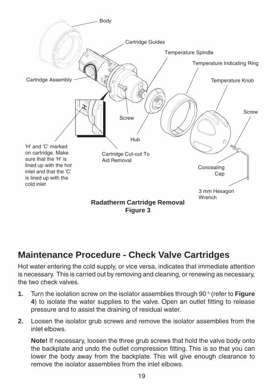
Radatherm Cartridge RemovalFigure 3
Temperature Knob
Temperature Indicating Ring
Hub
ScrewScrew
Cartridge Assembly
3 mm HexagonWrench
Body
Cartridge Cut-out ToAid Removal
'H' and 'C' markedon cartridge. Makesure that the 'H' islined up with the hotinlet and that the 'C'is lined up with thecold inlet
Cartridge Guides
Temperature Spindle
Maintenance Procedure - Check Valve CartridgesHot water entering the cold supply, or vice versa, indicates that immediate attentionis necessary. This is carried out by removing and cleaning, or renewing as necessary,the two check valves.
1. Turn the isolation screw on the isolator assemblies through 90 o (refer to Figure4) to isolate the water supplies to the valve. Open an outlet fitting to releasepressure and to assist the draining of residual water.
2. Loosen the isolator grub screws and remove the isolator assemblies from theinlet elbows.
Note! If necessary, loosen the three grub screws that hold the valve body ontothe backplate and undo the outlet compression fitting. This is so that you canlower the body away from the backplate. This will give enough clearance toremove the isolator assemblies from the inlet elbows.
ConcealingCap
20
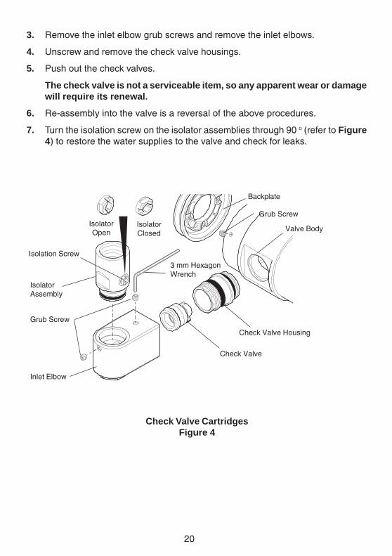
3. Remove the inlet elbow grub screws and remove the inlet elbows.
4. Unscrew and remove the check valve housings.
5. Push out the check valves.
The check valve is not a serviceable item, so any apparent wear or damagewill require its renewal.
6. Re-assembly into the valve is a reversal of the above procedures.
7. Turn the isolation screw on the isolator assemblies through 90 o (refer to Figure4) to restore the water supplies to the valve and check for leaks.
Check Valve CartridgesFigure 4
Backplate
Isolation Screw
IsolatorAssembly
Valve Body
Check Valve Housing
Check Valve
3 mm HexagonWrench
Grub Screw
Grub Screw
Inlet Elbow
IsolatorOpen
IsolatorClosed
21
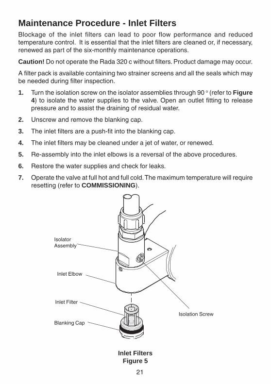
Maintenance Procedure - Inlet FiltersBlockage of the inlet filters can lead to poor flow performance and reducedtemperature control. It is essential that the inlet filters are cleaned or, if necessary,renewed as part of the six-monthly maintenance operations.
Caution! Do not operate the Rada 320 c without filters. Product damage may occur.
A filter pack is available containing two strainer screens and all the seals which maybe needed during filter inspection.
1. Turn the isolation screw on the isolator assemblies through 90 o (refer to Figure4) to isolate the water supplies to the valve. Open an outlet fitting to releasepressure and to assist the draining of residual water.
2. Unscrew and remove the blanking cap.
3. The inlet filters are a push-fit into the blanking cap.
4. The inlet filters may be cleaned under a jet of water, or renewed.
5. Re-assembly into the inlet elbows is a reversal of the above procedures.
6. Restore the water supplies and check for leaks.
7. Operate the valve at full hot and full cold. The maximum temperature will requireresetting (refer to COMMISSIONING).
Isolation Screw
IsolatorAssembly
Blanking Cap
Inlet Filter
Inlet Elbow
Inlet FiltersFigure 5
22
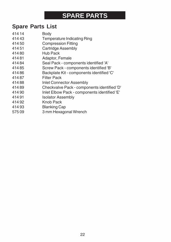
SPARE PARTS
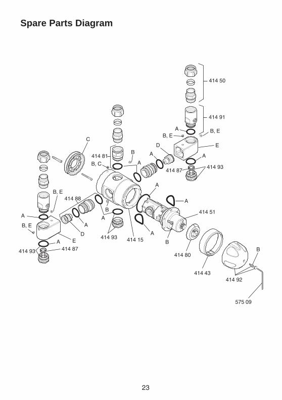
Spare Parts List414 14 Body414 43 Temperature Indicating Ring414 50 Compression Fitting414 51 Cartridge Assembly414 80 Hub Pack414 81 Adaptor, Female414 84 Seal Pack - components identified 'A'414 85 Screw Pack - components identified 'B'414 86 Backplate Kit - components identified 'C'414 87 Filter Pack414 88 Inlet Connector Assembly414 89 Checkvalve Pack - components identified 'D'414 90 Inlet Elbow Pack - components identified 'E'414 91 Isolator Assembly414 92 Knob Pack414 93 Blanking Cap575 09 3 mm Hexagonal Wrench
23
Spare Parts Diagram
E
414 93
414 80
414 43
575 09
414 92
414 15414 93
414 93
414 91
A
A AA
A
A
A
A
A
B, E
B
B, E
BB
B, C
B
B, E
B, E
414 87
C
414 87
D
D
414 81
E
414 51
414 88
A
A
414 50
24
CUSTOMER CARE
GuaranteeThis product is guaranteed against any defect of materials or workmanship for one year from the date ofpurchase, provided that the product has been installed correctly and used in accordance with theinstructions supplied.Any part found to be defective during the guarantee period will be replaced or repaired - at our option -without charge, provided that the product has been properly used and maintained.Routine cleaning and maintenance should be carried out in accordance with the instructions supplied.The product should not be modified or repaired except by a person authorised by Rada.
Your statutory rights are in no way affected by this guarantee.
After Sales Service - how we can help youWe have a network of fully trained staff ready to provide assistance, should you experience any difficultyoperating your Rada equipment.
Spare PartsAll functional parts of Rada products are kept for up to ten years from the date of final manufacture.If during that period, our stock of a particular part is exhausted we will, as an alternative, provide anequivalent new product or part at a price equating to the cost of repair to the old, bearing in mind the ageof the product.
Customer Care PolicyIf within a short time of installation the product does not function correctly, first check with the operationand maintenance advice provided in this Manual to see if the difficulty can be overcome.Failing this, contact your installer to ensure that the product has been installed and commissioned in fullaccord with our detailed installation instructions.If this does not resolve the difficulty, please ring your nearest Rada contact who will give every assistanceand, if appropriate, arrange for the local Service Engineer or Agent to call on a mutually agreeable date.
Contact:
BS EN ISO 9001 : 1994Reg. No. FM 14648
Rada is a registered trade mark ofKohler Mira Limited.The company reserves the right to alterproduct specifications without notice.
Rada ControlsCromwell Road,Cheltenham, England,GL52 5EP, UK.Tel.: + 44 (0)870 600 0221
Fax.: + 44 (0)1242 221925
P3225/2 © Kohler Mira Limited, June 2003