Embed Size (px)
Citation preview

Technical description ........................................ 2Delivery .......................................................... 2Advantages ..................................................... 2Technical data ................................................. 2Construction and function ................................. 2Handling ......................................................... 2Hood operation ................................................ 2Mounting example ............................................ 3Working area ................................................... 3Pressure loss ................................................... 3Alternative system layouts ................................. 4Complementary products and accessories .......... 5Mounting instruction ..................................... 6 - 9Maintenance instruction ............................ 10 - 11Spare part drawing ..................................... 12-13
Product manualJunior LM-2
THIS MANUAL SHOULD BE HANDED OVERAND KEPT BY THE SERVICE DEPARTMENT
AFTER THE INSTALLATION!
Thank you for buying a PlymoVent product.Before you unpack and put it into operation please read
this product manual, and follow the instructions.
USA/CAN010228
Table of contents: Page:
PlymoVent Corp.375 Raritan Center Parkway,Edison New Jersey 08837, USATel: +1 (732) 417 0808Fax: +1 (732) 417 1818
PlymoVent Canada Inc.6615 Ordan Drive, Unit # 3Mississauga, Ontario L5T 1X2, CanadaTel: +1 (905) 564 4748Fax: +1 (905) 564 4609

LM/USA/CAN/2/13
TECHNICAL DESCRIPTIONBSAB no: T0.31Ser.no: LM/TBDate: Sept-97Replace: Jan-95
JuniorLM-2
Junior LM-2
Construction and function
The PlymoVent Junior, LM-2, is an efficient and versatile fume extractor, especially designed forbenchwork. Perfect for schools, small working booths and any area with a low ceiling height.The extraction arm is based on a telescopic tube, allowing it to be extended to give a 2 m, 6,6'working radius and compressed to 1m, 3,3'. The spring-balancing together with the externalcounter-weight ensures that the hood stays exactly where you position it. The arm is fitted with aspring-balance which enables it to be moved from a vertical to a horizontal position in one easymovement.The arm can be turned through 300° due to PlymoVent's renow-ned ball-bearing joint. This is fittedtogether with an adjustable friction brake in the wall mounting bracket. All movement of the armis controlled from the hood. Extension hoses (FSL-1, SLE-20 or SLE-30) can easily be connected tothe arm after releasing the simple catch and removing the hood.
DeliveryThe LM-2 is delivered complete with wall mounting bracket, arm, hose and hood with damper.Advantages• Precise and easy positioning thanks to the counterweight
system which balances the hood.• Spring assisted vertical movement.• Flexible working radius due to the ”telescopic” operation.• Small and compact. Ideal for confined working areas
and low ceiling heights.• The one and only benchwork extractor.• Wide coverage – can easily be turned through 300°.
Technical data
A Wall mounting bracket withball-bearings and inlet spigot Ø160 mm, 6,3".
B Counterweight and counterweight tube.C Arm bracket.D Tensioned spring.E Three-part square-section telescopic tube with plastic bushes.F Joints with friction pads for adjustment of tension.G Flame-proof double skin flexible hose of PVC coated woven polyamide
with internal steel spiral. (Resistant to 85°C when in continous use).H Universal joint.I Hood collar with manual shut-off damper.J Hood constructed from sheet steel, with safety mesh and quick-fit coupling.
Hood opening Ø300 mm, 11,8". Large comfortable circular handle Ø300mm, 11,8".
Hood operationThe black enamelled ano-dised metalhood can be angled 110° forwards,backwards and to the sides. Large,360°, ring handle, Ø300 mm, 11,8".
Handling1. 360° ring handle for positioning of the
hood. Can be reached from all sides.2. Damper control knob.3. Quick-fit catch for simple exchange
of extension hose and hood.4. Switch for light cartridge
(seeaccessories HL-20/24).5. Switch for manual start/stop
of fan or damper (see accessoriesSA-24, ES-90 or ASE-12).
Prod.no:
MaxLength
MinLength
HoseDiameter
Recommended Airflow atthe Hood in m3/h/ cfm
800-1200 m3/h, 470-706 cfm160 mm,6,3"1,0 m,3,3'2,0 m, 6,6'LM-2
LM/USA/CAN/3/13
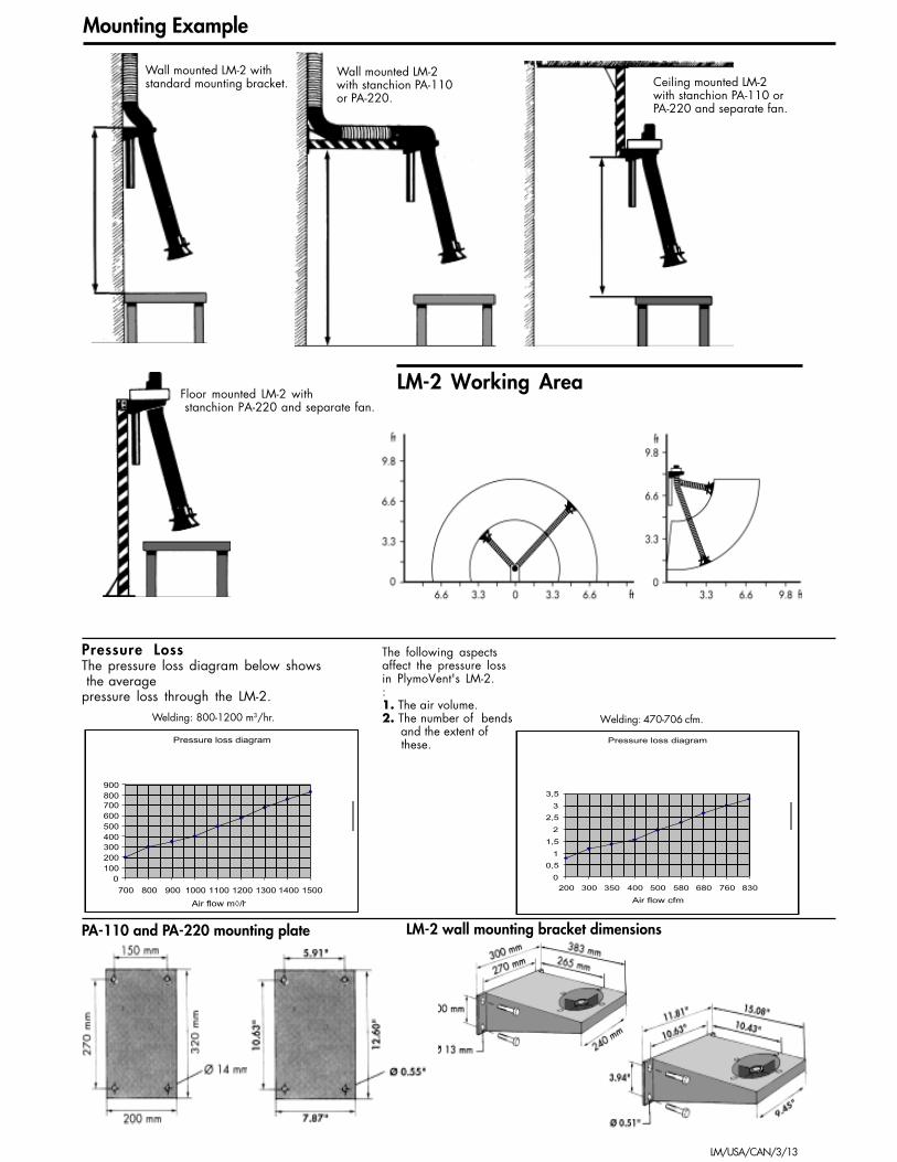
Pressure LossThe pressure loss diagram below shows the averagepressure loss through the LM-2.
Mounting Example
PA-110 and PA-220 mounting plate
Welding: 800-1200 m3/hr.
LM-2 wall mounting bracket dimensions
LM-2 Working Area
Wall mounted LM-2 withstandard mounting bracket.
Wall mounted LM-2with stanchion PA-110or PA-220.
Ceiling mounted LM-2with stanchion PA-110 orPA-220 and separate fan.
Floor mounted LM-2 with stanchion PA-220 and separate fan.
The following aspectsaffect the pressure lossin PlymoVent's LM-2.:1. The air volume.2. The number of bends and the extent of these.Pressure loss diagram
0100200300400500600700800900
700 800 900 1000 1100 1200 1300 1400 1500
Air flow m◊/h
Pressure loss diagram
0
0,5
1
1,5
2
2,5
3
3,5
200 300 350 400 500 580 680 760 830
Air flow cfm
Welding: 470-706 cfm.

LM/USA/CAN/4/13
ES90
ES90
Back draught damper
Interlink 12 V
AC 230/400 V 3
Control unit M 1000
Mainfusebox
´Low pressure fan
ES90
AC 230/400 V 3~
AC 230 V 1~
Interlink 12V
Control unitM-1000
AC 230/400 V 3~
Central fan
Motoriseddamper 24 V
ASE-12 ASE-12ASE-12
Alternative System Layouts
Alt. 4
Alt. 3
Alt. 2
Alt. 1
Central system: 3 X LM-2 with onecentral FS-4700 fan.Recommended fan per no of arms:FS-3000: 2-3 arms.FS-4700: 3-4 arms.FA-6000: 4-5 arms.
Central system: 3 X LM-2 fitted with ASE-12automatic dampers, M-1000 control unitand one central fan.Recommended fan per no. of arms:FS-2100: 2-4 arms.FS-3000: 3-6 arms.FS-4700: 4-8 arms.FA-6000: 4-8 arms.
As every working-place is unique, the aboverecommendations are only applicable fortheoretically calculated examples.
Central system: 3 X LM-2 connectedto one electrostatic filter EF type.Recommended filter per no. of arms:EF-2000: 1-2 arms*EF-3000: 1-3 arms*EF-5000: 2-5 arms*When more stations are required the systemcan be fitted with ASE-12 automatic dampers.
*For continuous use.
Central system: 3 X LM-2 fitted with separatefans and ES-90 energy savers, interlinked toa control unit M-1000 for switching thecentralised low pressure fan.See technical data sheet on energysaver ES-90 for further information.

LM/USA/CAN/5/13
Spiral CableExtendable up to 3 m. To be used when installingswitch assembly for PlymoVent LM-2 andExtractor Cranes ”Plymoth®”.Prod. no: SK-300
Complementary Products and Accessories
FanProdno.
AirflowCFM
Freeblowing
MotorHP/Phase
Airflow CFMat the hood ofthe LM-2
82582510601300
1300
2000
2840
3540
FUA-1300FUA-1301FUA-1800FUA-2100
FUA-2101
FS-3000
FS-4700
FA-6000
1/2 HP, 3 phase1/2 HP, 1 phase3/4 HP, 3 phase1 HP, 3 phase
1 HP, 1 phase
1.5 HP, 3 phase
3 HP, 3 phase
7.5 HP, 3 phase
1 LM = 5901 LM = 5901 LM = 7401 LM = 8252 LM = 380 ea
1 LM = 8252 LM = 380 ea
2 LM = 765 ea3 LM = 500 ea
3 LM = 765 ea4 LM = 560 ea
4 LM = 765 ea5 LM = 620 ea
F S
F U ANOTE: ALL FANS MUST BE FITTED WITH RELEVANTMOTOR OVERLOAD (NOT INCLUDED).
StanchionAccessory for ceiling, flooror wall mounting of LM-2.Length: 3.6 ft. Prod No: PA-110.Length: 7.2 ft. Prod No: PA-220.
Halogen Lamp CartridgeTo be fitted in the hood. Consists of 20W/24Vhalogen lamp, switch assembly and 32.8 ft cable.Must be complemented withtransformer TR-24 or starter SA-24.Prod No. SK-20/24
Transformer115 VAC-24V/sec. Transformer forhalogen lamp cartridge HL-20/24.Prod No. TR-24
Control UnitFor automatic start or stop of a central fan upto 5 HP in a system with several extractors.To be used in conjunction with the EnergySaver or Automatic Damper. Line supply:115 thru 460 VAC.Prod No. M-1000
StarterFor manual start/stop of the fan up to 5 HP via aswitch in the hood. Complete with switch assemblyand 32.8 ft cable. Built-in contactor must be fittedwith relevant fan-motor overload (not included).Line supply: 115 thru 460 VAC.Prod No. SA-24/75 includes 75 VA/24Vtransformer for halogen lamp on one workstation.
Semi-rigid Extension HoseFor all extraction arms 6.30" in diameter. Connectswith quick-fit coupling. Flexible and adjustable,4.92 diameter. Length 3.3 ft.Prod No. FSL-1
Extension HoseØ 6.30" extension hose with quick-fit coupling forconnection to the fume extraction arm. PVCcoated woven glassfibre with inner steel spiralsupport.Hood with double magnetic foot and handlefor easy positioning.Prod No. SLE-20, 6.6 ft in lengthProd No. SLE-30, 9.8 ft in length
Electrostatic FiltersClean the air so efficiently (up to 99.9%) thatyou may recirculate the already heated air intothe workshop. Huge energy savings. Alsoexcellent for filtering oilmist. Are availablein sizes up to 2950 CFM.For more information, see technical datafor oilmist and Electrostatic Filters (EF/EFO).
Fans FUAFUA fans are attached directly to the LM-2 mountingbracket. Available in three sizes with freeblowing airvolumes of 825, 1060 and 1300 CFM. A uniqueanti-spark impeller made from aluminium givesmaximum security. For wall- or ceiling mounted,choose "FS"-fan stand models 1300, 1800 or2100. In a system with more than oneextractor, we recommend the wallmounted FS-3000, 4700 or FA-6000.
Automatic DamperFully automatic motor driven damper for fittingto Ø 6.30" duct. Adjustable overrun periodbetween 7 seconds and 6 minutes, to cap-ture after-fume. Inductive sensor clampwith 16.4 ft of cable is included as stan-dard. Line supply: 115 thru 460 VAC.Also includes switch assembly (S-100)for manual control from the hood.Prod No. ASE-12
Energy SaverFor autom. start/stop of fan. Adjustable overrunperiod of between 7 sec. - 6 min. Incl. inductivesensor clamp with 16.4 ft of cable. Built-in contac-tor for up to 5 HP fan must be fitted with relevantfan-motor overload (not included).Line supply: 115 thru 460 VAC.Prod No. ES-90-005 Incl. 75 VA/24Vtransformer. For one arm with light and one fan.
* Other voltages are available
* Other voltages are available
* Other voltages are available
* Other voltages are available
* Other voltages are available
* Other voltages are available

LM/USA/CAN/6/13
BSAB no: T0.31Ser.no: LM/MADate: Sept-97Replace: Jan-95
MOUNTING INSTRUCTION
JUNIORLM-2
Pos no DESCRIPTION
A Wall mounting bracketB CounterweightC LM-2D Hood collarE HoodF SpigotG Fan
LM/USA/CAN/7/13
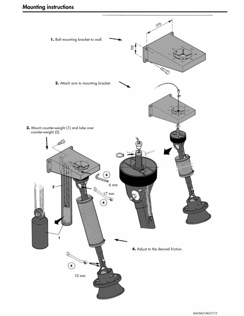
10 mm
17 mm
6 mm
Mounting instructions
1. Bolt mounting bracket to wall.
2. Attach arm to mounting bracket.
3. Mount counter-weight (1) and tube overcounter-weight (2).
4. Adjust to the desired friction.

LM/USA/CAN/8/13
5. Pull over the rubber seal.
6. Fix flexible hose in place, usingjubilee clips as supplied.

LM/USA/CAN/9/13
For individual fan.For central system.
7. Mount spigot Ø 160 mm, 6,3".
LM/USA/CAN/10/13
BSAB no: T0.31Ser.no: LM/DSDate: Sept-97Replace: Jan-95
MAINTENANCEINSTRUCTION
JUNIORLM-2
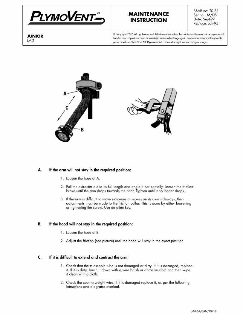
A. If the arm will not stay in the required position:
1. Loosen the hose at A.
2. Pull the extractor out to its full length and angle it horizontally. Loosen the frictionbrake until the arm drops towards the floor. Tighten until it no longer drops.
3. If the arm is difficult to move sideways or moves on its own sideways, thenadjustments must be made to the friction collar. This is done by either looseningor tightening the screw. Use an allen key.
B. If the hood will not stay in the required position:
1. Loosen the hose at B.
2. Adjust the friction (see picture) until the hood will stay in the exact position.
C. If it is difficult to extend and contract the arm:
1. Check that the telescopic tube is not damaged or dirty. If it is damaged, replaceit. If it is dirty, brush it down with a wire brush or abrasive cloth and then wipeit clean with a cloth.
2. Check the counterweight wire. If it is damaged replace it, as per the followingintructions and diagrams overleaf.

LM/USA/CAN/11/13
To change wire
1. Unbolt the counterweight tube.
2. Loosen both jubilee clips and push the hose together in the middle of the telescopic tube.
3. Detach the counterweight.
4. Unscrew the bolt holding the hood attachment to the telescopic tube, and remove thehood attachment carefully. Push the telescopic section together until the old wire comesthrough at the lower end.
5. Put the upper end of the new wire through the eye of the old wire. Pull at the upper endof the old wire until the new wire at the top of the tube. Pull the new wire at the top untilthe eye at the lower end is in line with the hole for the bolt. Push the hood attachmentonto the telescopic tube very carefully and fasten the bolt.
6. Tie the new wire to the counterweight as before.
7. Mount the new wire as shown on picture.
8. Re-position the counterweight tube and the hose.
LM/USA/CAN/12/13
BSAB no: T0.31Ser.no: LM/RRDate: Sept-97Replace: Jan-95
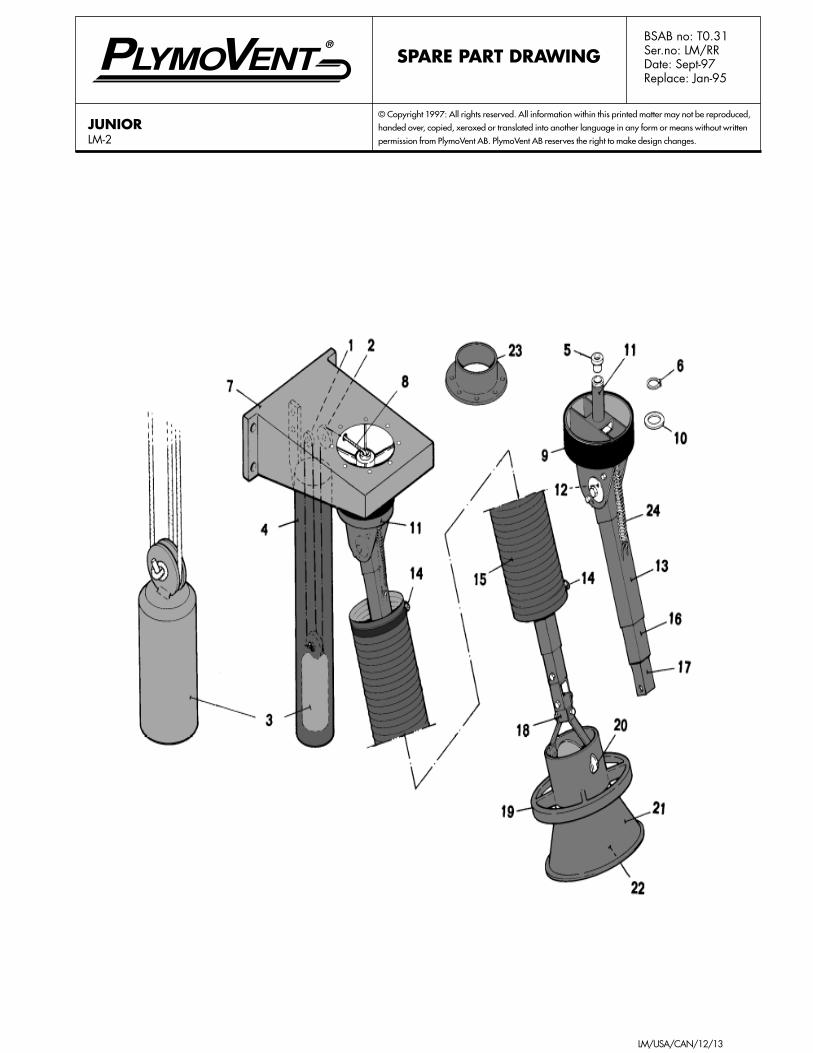
SPARE PART DRAWING
JUNIORLM-2
LM/USA/CAN/13/13
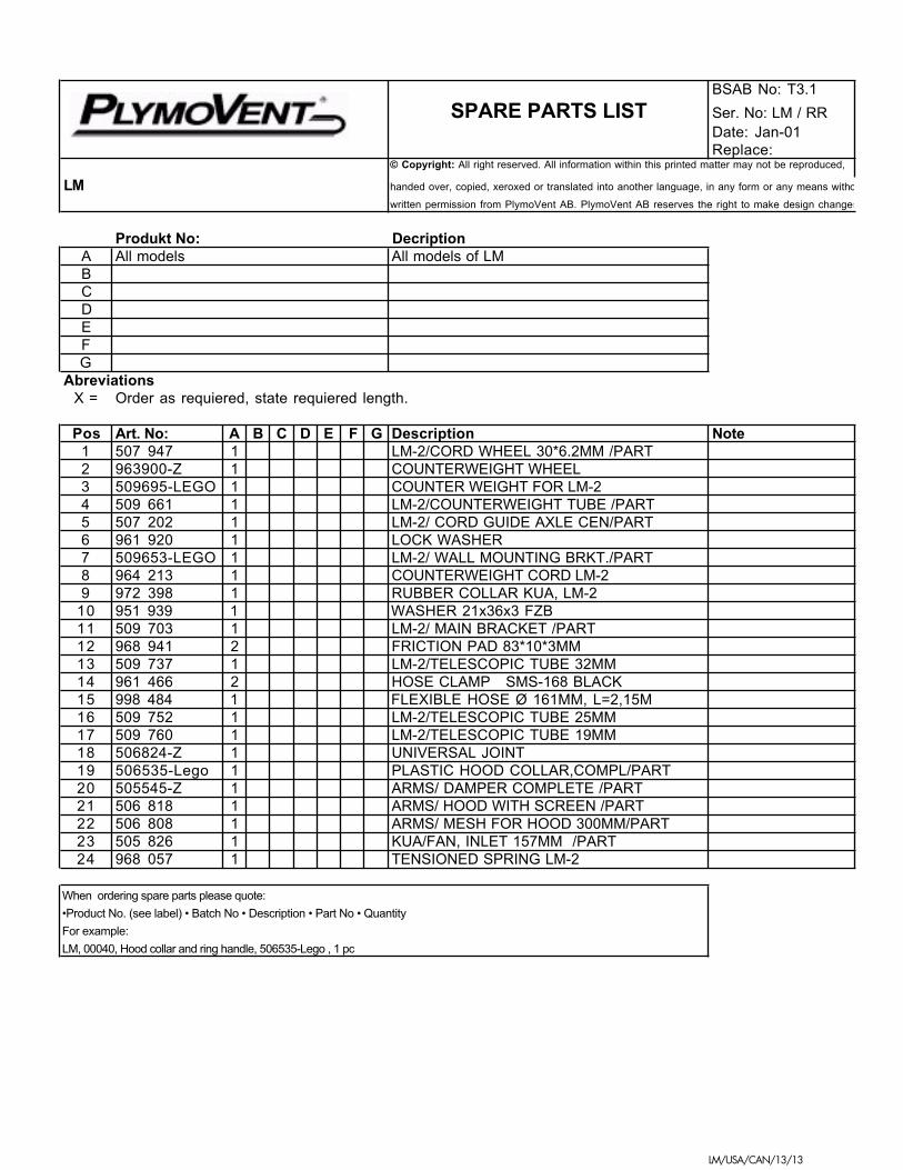
BSAB No: T3.1
SPARE PARTS LIST Ser. No: LM / RRDate: Jan-01Replace:
© Copyright: All right reserved. All information within this printed matter may not be reproduced,
LM handed over, copied, xeroxed or translated into another language, in any form or any means witho
written permission from PlymoVent AB. PlymoVent AB reserves the right to make design changes
Produkt No: DecriptionA All models All models of LMBCDEFG
Abreviations X = Order as requiered, state requiered length.
Pos Art. No: A B C D E F G Description Note1 507 947 1 LM-2/CORD WHEEL 30*6.2MM /PART2 963900-Z 1 COUNTERWEIGHT WHEEL3 509695-LEGO 1 COUNTER WEIGHT FOR LM-24 509 661 1 LM-2/COUNTERWEIGHT TUBE /PART5 507 202 1 LM-2/ CORD GUIDE AXLE CEN/PART6 961 920 1 LOCK WASHER7 509653-LEGO 1 LM-2/ WALL MOUNTING BRKT./PART8 964 213 1 COUNTERWEIGHT CORD LM-29 972 398 1 RUBBER COLLAR KUA, LM-2
10 951 939 1 WASHER 21x36x3 FZB11 509 703 1 LM-2/ MAIN BRACKET /PART12 968 941 2 FRICTION PAD 83*10*3MM13 509 737 1 LM-2/TELESCOPIC TUBE 32MM14 961 466 2 HOSE CLAMP SMS-168 BLACK15 998 484 1 FLEXIBLE HOSE Ø 161MM, L=2,15M16 509 752 1 LM-2/TELESCOPIC TUBE 25MM17 509 760 1 LM-2/TELESCOPIC TUBE 19MM18 506824-Z 1 UNIVERSAL JOINT19 506535-Lego 1 PLASTIC HOOD COLLAR,COMPL/PART20 505545-Z 1 ARMS/ DAMPER COMPLETE /PART21 506 818 1 ARMS/ HOOD WITH SCREEN /PART22 506 808 1 ARMS/ MESH FOR HOOD 300MM/PART23 505 826 1 KUA/FAN, INLET 157MM /PART24 968 057 1 TENSIONED SPRING LM-2
When ordering spare parts please quote:
•Product No. (see label) • Batch No • Description • Part No • Quantity
For example:
LM, 00040, Hood collar and ring handle, 506535-Lego , 1 pc