Embed Size (px)
Citation preview

P R A C T I C A L , E F F I C I E N T & S U S T A I N A B L E B U I L D I N G S E R V I C E S S O L U T I O N S
PRODUCT MANUALT R 2 0 0 0 0 9 . r 2
Stainless Steel RangeSSB, SSI, and SST
Installation, Operation, andMaintenanceManual
P R A C T I C A L , E F F I C I E N T & S U S T A I N A B L E B U I L D I N G S E R V I C E S S O L U T I O N S
Stainless Steel SSB, SSI, SST range - Installation, Operation, and Maintenance Manual 2
WarningsThis manual should be read and understood prior to installation or operation of any Adveco SSB, SSI or SST stainless steel vessel. Failure to read this manual or follow its printed instructions may lead to personal injury, damage to the vessel and damage to the water heating installation. These instructions should be kept in a safe and accessible place near the vessel.
Vessels should be stored in a safe place prior to installation to prevent damage.
Copyright © 2018 Adveco Ltd. All rights reserved. No part of this publication may be copied, reproduced, altered and/or published by any means without the prior written approval of Adveco Ltd. Any brand names mentioned within this publication are registered trademarks of their respective owners.
Adveco Ltd. reserves the right to modify specifications in this manual at any time and without notification.
Adveco Ltd. accepts no liability for third party claims arising from unauthorised use and/or use other than as directed within this manual.
How to Use This ManualAll general information, instructions and specifications listed within this manual applies to the full range of SSB, SSI and SST vessels. Any information relevant to only specific SSI or SST vessels is contained within dedicated sections and is clearly identifiable by section titles.
All information unless otherwise stated is applicable to installations in any country. Any information that is relevant to a particular country only is separated and located within clearly marked sections.
For any queries or issues not covered by the scope of this manual, please contact the Adveco Technical Department using the contact details provided on page 26.
3
ContentsPage
Product Description 4
Installation Instructions 1. Responsibilities of the User 5 2. Responsibilities of the Installer / Designer 6 3. Requirements of the Installation 6 4. Location & Handling 7 5. Tank Connections 8 6. Primary Pipework 9 7. Secondary Pipework 10 8. Discharge Pipework 12 9. Secondary Return Pipework 13 10. Shunt / Destratification Pump 13 11. Multiple Tanks 14 12. Controls 15
Maintenance Operations 16
General Specifications 17
Flange Specifications 18
Further Specification: SSI and SST (Bottom Coil Only) 19
Further Specification: SST (Top Coil Only and Combined Coils) 20
Technical Drawings 1. SSB Buffer Vessel and SSI Indirect Vessel 21 2. SST Twin-Coil Vessel and SST Combined Coil Vessel 22 3. SSB-E Electric Vessel Options 23 4. SSB-D Direct Vessel 24
Spares and Ancillary Items 25
Contact Details & Warranty Information 26
P R A C T I C A L , E F F I C I E N T & S U S T A I N A B L E B U I L D I N G S E R V I C E S S O L U T I O N S
Stainless Steel SSB, SSI, SST range - Installation, Operation, and Maintenance Manual 4
Product DescriptionAdveco Stainless Steel Cylinders: SSB, SSI, SSTAdveco Stainless Steel Cylinders are a versatile, modular range of domestic hot water vessels that can be fitted with up to two high-capacity stainless steel indirect heating coils or specialised flanges and immersion heaters as required by the application. The range is divided into three types of vessel depending on the number of heat exchange coils included:
Stainless Steel Buffer (hereafter “SSB”) vessels are supplied with two blank flanges and zero heat exchange coils, and primarily serve as buffer vessels only.
Stainless Steel Indirect (hereafter “SSI”) vessels are supplied with one heat exchange coil fitted into the lower flange of the tank, with a blank flange fitted into the top.
Stainless Steel Twin-Coil (hereafter “SST”) vessels are supplied with two heat exchange coils that can either operate inde-pendently or be connected together to serve a single high-capacity heat source.
The full range of stainless steel vessels are compatible with direct heating options by the inclusion of the Adveco range of electric immersion heaters.
Two subtypes of the SSB range are also available by substiting one or both standard blank flanges for alternative special-ised flanges:
The Stainless Steel Buffer Electric (hereafter "SSB-E" or "SSB-E2" depending on the number of electric flanges included) feature one to two electric element mounting flanges, each capable of housing one or two Adveco electric immersion elements. This makes it possible for multiple immersion heaters to be combined with a single tank, resulting in a highly adaptable electric water heater to serve domestic hot water systems.
The Stainless Steel Buffer Direct (hereafter "SSB-D") range features a direct vessel connection flange in place of the lowest blank flange, allowing the stainless steel vessel to be used as a buffer with a direct connection to a water heater.
The Technical Drawings located on pages 21-24 can be consulted for a visual reference to the various vessels within the Adveco Stainless Steel Cylinder range.
The Adveco Stainless Steel Cylinder range is designed, manufactured, and tested in the EU to the requirements of:
The Pressure Equipment Directive EN 12897:2016
The scope of EN 12897:2016 covers indirectly heated, mains pressure storage water heaters, with or without immersion heater backup, up to 1000 litres and 10 bar. The SSB, SSI and SST range of stainless steel vessels up to 1000 litres have been produced to the requirements of this standard.
Vessels with storage capacities of 1000 litres and greater have been designed and manufactured within the spirit of this standard, and have been type tested in accordance with section 6.2. Production units in this category are tested to section 6.3. This supports the requirement for sound engineering as prescribed by the Pressure Equipment Directive for vessels covered by Article 3, Paragraph 3.
The full range of stainless steel vessels are WRAS approved products, with approval reference 1605319.
5
Installation Instructions1. Responsibilities of the UserHot water systems pose a potential risk for building occupants regarding temperature and biological risks. It is the responsibility of the building controller to assess the risk to the occupants of scalding or Legionella and put in place suitable steps to protect the occupants.
The risk assessment must be carried out by someone suitably qualified. The following documents offer guidance and assistance on responsibilities:
ACOP L8, 2014 HSG274 Part 2 Health and Safety at Work Act Workplace (Health, Safety and Welfare) Regulations HTM 04 01 Part A and B Building Regulations Part G BS EN 806 All parts CEN/TR 16355
And any other standards, laws, guidelines, or rules in force in the location of the installation, past or future, that are current at the time of installation. This installation manual complements these rules and must not be considered to override them in any way.
Following the commissioning of a system and in compliance with the procedures and advice contained within this manual, responsibility lies with the building controller to maintain a safe standard of operation and regular maintenance procedures as required by the risk assessment. This includes ensuring that the unit is not operated at temperatures or pressures in excess of those stated on the vessel data plate. Nor should the vessel be exposed to a full or partial vacuum, such as can be present during draw-off or drainage of the unit while the cold feed or vent are closed or obstructed.
Failure to maintain a minimum of annual maintenance may void any and all warranties. Full maintenance procedures should only be carried out by a suitably qualified person. Basic maintenance regimes, as determined through risk assessment, should be carried out by the user as directed on page 16.
Adveco Ltd. advise that heating systems in unoccupied premises, or that are subjected to long periods of shutdown, should be drained down according to the procedure on page 16, to remove the risk of failure and/or damage occurring while the system is not being monitored.
P R A C T I C A L , E F F I C I E N T & S U S T A I N A B L E B U I L D I N G S E R V I C E S S O L U T I O N S
Stainless Steel SSB, SSI, SST range - Installation, Operation, and Maintenance Manual 6
Installation Instructions2. Responsibilities of the Installer / DesignerIn compliance with the procedures and advice contained within this manual, responsibility lies with the installer to ensure that the vessels are correctly and safely installed in line with all local regulations and laws. In all cases, the relevant laws and regulations take precedence over the instructions contained within this manual.
3. Requirements of the Installation
The SSB, SSI, and SST range of stainless steel vessels are suitable for use with storage or heating of potable water in installations up to a maximum pressure of 6 bar. Any unvented cylinder installation should be notified to Building Control. This is best done through a Competent Persons Scheme by installers holding a valid unvented domestic hot water ticket.
The following documents set out the standards of installation that must be adhered to: EN 806 All Parts EN 8558:2015
Note that the installation of any electric heating element requires the use of an earthed power supply.
7
Installation Instructions4. Location & HandlingSuitable methods of moving a vessel include the use of a forklift truck where the vessel is securely fixed to a pallet capable of supporting its weight, or by boom crane using adequate textile slings of suitable capacity to lift the weight of the tank. Vessels should not be lifted using the insulation, by chains, or by straps that may damage the insulation, connections, or walls of the tank. Care should be taken when moving or lifting to minimise the risk of damage to the vessel.
The vessel must be located inside the building and positioned on a level base capable of supporting the unit when full. Floor loading calculations should include the total filled weight, being equivalent to the sum of the empty weight of the vessel and the weight of any installed coils or flanges, plus the water volume in litres (where 1 litre of water weighs 1 kg). For tank and coil weights, consult pages 17-18.
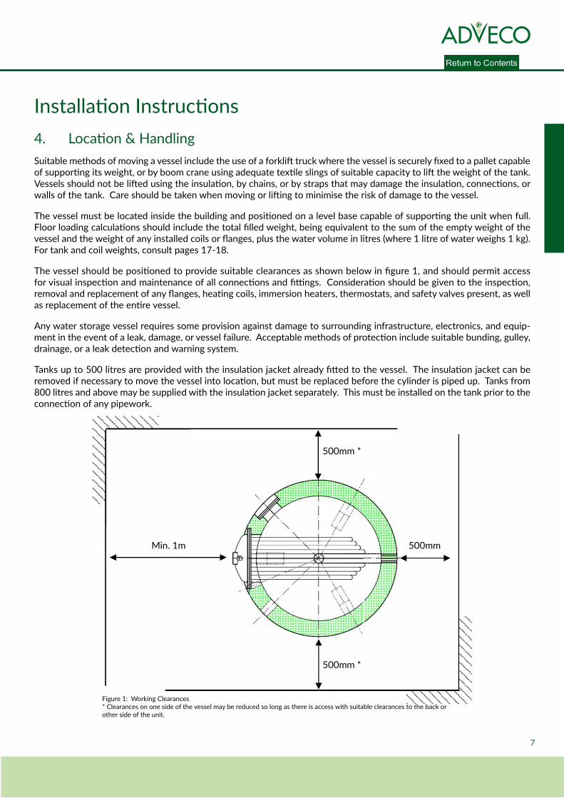
The vessel should be positioned to provide suitable clearances as shown below in figure 1, and should permit access for visual inspection and maintenance of all connections and fittings. Consideration should be given to the inspection, removal and replacement of any flanges, heating coils, immersion heaters, thermostats, and safety valves present, as well as replacement of the entire vessel.
Any water storage vessel requires some provision against damage to surrounding infrastructure, electronics, and equip-ment in the event of a leak, damage, or vessel failure. Acceptable methods of protection include suitable bunding, gulley, drainage, or a leak detection and warning system.
Tanks up to 500 litres are provided with the insulation jacket already fitted to the vessel. The insulation jacket can be removed if necessary to move the vessel into location, but must be replaced before the cylinder is piped up. Tanks from 800 litres and above may be supplied with the insulation jacket separately. This must be installed on the tank prior to the connection of any pipework.
Figure 1: Working Clearances* Clearances on one side of the vessel may be reduced so long as there is access with suitable clearances to the back or other side of the unit.
Min. 1m
500mm *
500mm *
500mm
P R A C T I C A L , E F F I C I E N T & S U S T A I N A B L E B U I L D I N G S E R V I C E S S O L U T I O N S
Stainless Steel SSB, SSI, SST range - Installation, Operation, and Maintenance Manual 8
Installation Instructions5. Tank Connections
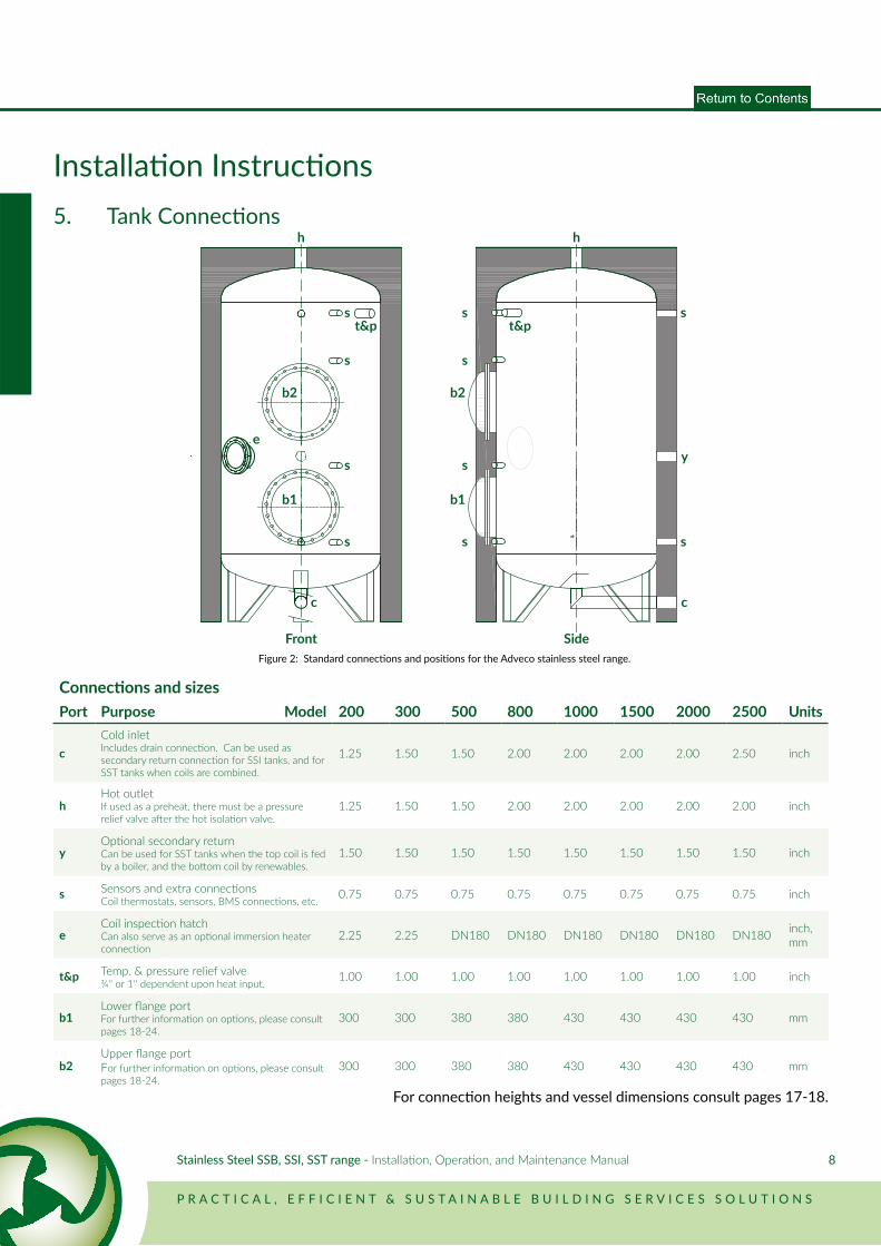
Connections and sizesPort Purpose Model 200 300 500 800 1000 1500 2000 2500 Units
cCold inletIncludes drain connection. Can be used as secondary return connection for SSI tanks, and for SST tanks when coils are combined.
1.25 1.50 1.50 2.00 2.00 2.00 2.00 2.50 inch
hHot outletIf used as a preheat, there must be a pressure relief valve after the hot isolation valve.
1.25 1.50 1.50 2.00 2.00 2.00 2.00 2.00 inch
yOptional secondary returnCan be used for SST tanks when the top coil is fed by a boiler, and the bottom coil by renewables.
1.50 1.50 1.50 1.50 1.50 1.50 1.50 1.50 inch
s Sensors and extra connectionsCoil thermostats, sensors, BMS connections, etc. 0.75 0.75 0.75 0.75 0.75 0.75 0.75 0.75 inch
eCoil inspection hatchCan also serve as an optional immersion heater connection
2.25 2.25 DN180 DN180 DN180 DN180 DN180 DN180 inch, mm
t&p Temp. & pressure relief valve¾'' or 1'' dependent upon heat input. 1.00 1.00 1.00 1.00 1.00 1.00 1.00 1.00 inch
b1Lower flange portFor further information on options, please consult pages 18-24.
300 300 380 380 430 430 430 430 mm
b2Upper flange portFor further information on options, please consult pages 18-24.
300 300 380 380 430 430 430 430 mm
For connection heights and vessel dimensions consult pages 17-18.
Figure 2: Standard connections and positions for the Adveco stainless steel range.
h
s
y
c
h
c
s
s
s
s
s
s
st&p
e
t&ps
s
b1
b2
b1
b2
Front Side
9
Installation Instructions6. Primary PipeworkThe stainless steel range of indirect tanks are produced with flanges for up to two removable coils, leading to three distinct product ranges depending on the number of coils installed. The SSB Stainless Steel Buffer range is provided with blank flanges and no coils installed. The SSI Stainless Steel Indirect range is supplied with a single coil mounted in the lower flange, and the SST Stainless Steel Twin-Coil range is provided with coils fitted into both flanges. As a result, the stainless steel range can cater for most hot water applications. The coils fitted within the SST can be used individually for two different heat sources, or can be combined by external, additional pipework (not supplied) to give a larger capacity system. With these combinations the vessel can be used as a preheater, afterheater, buffer or standalone water heating system.
Connections to the vessel should be made according to the locations and sizes denoted on pages 8 and 17. All pipework should be of an appropriate, non-corrosive material, and should be supported outside of the vessel to prevent excessive load bearing upon the tank connection points. Pipework should be arranged to facilitate suitable access to system components. Any flanged connections to the vessel must be tightened in a diametrically opposed sequence to prevent uneven loads across the connection.
While installing pipework, consideration should be given to removal of the coils for maintenance and cleaning of the tank. Valves and union type fittings are required. A drainage connection should be included downstream of the union fittings.
SST Combined CoilsFor larger capacity systems with one heat source, the two heating coils can be combined. The standard way to do this is in series so that the primary flows through the top coil and then through the bottom coil. To estimate the total kW capacity with both coils, based on an 80°C primary temperature, add the kW capacity for the top coil at 80°C to the kW capacity for the bottom coil at 70°C. For technical details on kW capacities at 70°C, on different temperatures, or if a more accurate calculation is required, please contact the Adveco Design Department.
SST Separate CoilsIn the case of two heat sources, the lower grade heat or less costly energy source should go into the bottom coil to act as a preheat. The more reliable source of high grade heat (usually a boiler) should be piped into the top coil.
Air ReliefEach coil has a 3/8 inch connection for an air bleed point to commission the coils. Air relief valves are not supplied as standard.
P R A C T I C A L , E F F I C I E N T & S U S T A I N A B L E B U I L D I N G S E R V I C E S S O L U T I O N S
Stainless Steel SSB, SSI, SST range - Installation, Operation, and Maintenance Manual 10
Installation Instructions7. Secondary PipeworkGeneralA standard installation will include the stainless steel cylinders as part of a mains-fed system. The pipework should be correctly sized to carry the maximum simultaneous demand of hot water for the building. This may or may not be the same size as the cold feed connection.
Cold FeedAll cold feed pipework must be fitted with safety equipment to prevent overpressure and allow for the expansion of hot water in the system. This must include a check valve and a pressure relief valve set normally to the maximum working pressure of the tank, but no more than 1.5 bar higher than the maximum working pressure in line with the regulations set out in EN 8558 section 4.3.29.1.
All mains-fed systems should additionally include a pressure reducing valve and strainer. The standard kit supplied by Adveco has a variable pressure reducing valve with settings available between 1 bar and 5.5 bar. The domestic hot water pressure must exceed the primary system pressure at all times to protect against contamination of the DHW in the unlikely event of a leak from the coil.
There must not be any type of isolation between the pressure relief valve and the vessel. Safety equipment should be installed at the cold inlet unless otherwise specified.
The cold feed equipment should be supplied as part of an unvented kit by Adveco Ltd., inclusive of an expansion vessel and temperature and pressure relief valve with a pressure setting at least 0.5 bar above the pressure relief valve setting but no more than 1.5 bar higher than the maximum working pressure of the tank, in line with EN 8558 section 4.3.29.1. A 3/4’’ inch valve is suitable for use with most indirect systems.
The expansion vessel should be calculated to be roughly 5% of the total hot water system volume for systems operating at around 3 bar. Please contact the Adveco Design Department to obtain a full calculation if required, or for high pressure applications. The expansion vessel pressure must be set equal to the cold fill pressure of the system, and must be set with no pressure on the wet side of the membrane. The expansion vessel must be situated on the cold feed pipe. For tanks arranged in series, only one expansion vessel should be used at the beginning of the system. Consideration may be given to flow-through type expansion vessels for systems identified as high risk.
The expansion vessel branch can have a lock shield valve so long as the relief valve is not on the same branch.
For further notes on tank and pipework arrangements, please refer to the Technical Drawings found on pages 21-24 of this manual.
11
Installation Instructions7. Secondary PipeworkDrainThe cold feed is located at the lowest part of the cylinder to meet anti-Legionella requirements. A drain should be installed in the cold feed at the lowest point, before the connection to the cylinder. The drain valve shall be of suitable size to allow draining of the tank in a reasonable amount of time. It is recommended that a 1/4 turn lever valve and plug or cap are used and that the valve size be one size smaller than the cold feed connection size. A suitable drain or gulley should be provided to allow draining of the tank.
Vented Installations:In case of a vented system the unvented kit can be omitted. From the hot flow there must be an uninterrupted open vent with no valves, of at least 19mm internal diameter, reaching above the water level of the cold water tank and discharging to a safe place (not into the cold tank). It is considered good practice to fit a temperature and pressure relief valve even on a vented system.
P R A C T I C A L , E F F I C I E N T & S U S T A I N A B L E B U I L D I N G S E R V I C E S S O L U T I O N S
Stainless Steel SSB, SSI, SST range - Installation, Operation, and Maintenance Manual 12
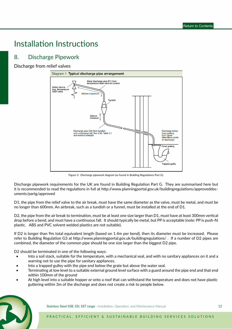
Installation Instructions8. Discharge PipeworkDischarge from relief valves
Discharge pipework requirements for the UK are found in Building Regulation Part G. They are summarised here but it is recommended to read the regulations in full at http://www.planningportal.gov.uk/buildingregulations/approveddoc-uments/partg/approved
D1, the pipe from the relief valve to the air break, must have the same diameter as the valve, must be metal, and must be no longer than 600mm. An airbreak, such as a tundish or a funnel, must be installed at the end of D1.
D2, the pipe from the air break to termination, must be at least one size larger than D1, must have at least 300mm vertical drop before a bend, and must have a continuous fall. It should typically be metal, but PP is acceptable (note: PP is push-fit plastic. ABS and PVC solvent welded plastics are not suitable).
If D2 is longer than 9m total equivalent length (based on 1.4m per bend), then its diameter must be increased. Please refer to Building Regulation G3 at http://www.planningportal.gov.uk/buildingregulations/ . If a number of D2 pipes are combined, the diameter of the common pipe should be one size larger than the biggest D2 pipe.
D2 should be terminated in one of the following ways: • Into a soil stack, suitable for the temperature, with a mechanical seal, and with no sanitary appliances on it and a warning not to use the pipe for sanitary appliances. • Into a trapped gulley with the pipe end below the grate but above the water seal. • Terminating at low level to a suitable external ground level surface with a guard around the pipe end and that end within 100mm of the ground • At high level into a suitable hopper or onto a roof that can withstand the temperature and does not have plastic guttering within 3m of the discharge and does not create a risk to people below.
Figure 3: Discharge pipework diagram (as found in Building Regulations Part G).
13
Installation Instructions9. Secondary Return PipeworkA secondary return is the best way to ensure that there is hot water at the outlets in a short amount of time. In some cases this could be done with trace heating, but the amount of electricity necessary to do this must be considered. In some small systems it is not necessary to use either, and the hot water can flow directly to the taps. The water at the furthest outlet must be 50°C within one minute (55°C in healthcare premises), although this may not be acceptable to all users and a secondary return arrangement should be considered for waiting times of longer than 20 seconds. In all cases, site legionella protection policy takes precedence over this document.
The secondary return pump should be sized to give a suitable flow of hot water around the system to ensure the returning temperature is at least 50°C. The pipework must be insulated. The pump must have a check valve on the positive side of the return pump to prevent cold flow to the hot outlets.
For SSB and SSI vessel applications, the secondary should return into the cold feed of the water heater.
For the SST Twin-Coil range, the secondary should enter the hot water system above any low grade heat sources, just before the final high grade heat source. For a standard indirect water heater installation where both coils are connected together from one heat source, the return should go into the cold feed downstream of the unvented kit / inlet combination safety group. In cases where two heat sources are used, the secondary return should be piped into the centre of the tank.
10. Shunt / Destratification PumpIn installations where the secondary return is piped into the cold feed, it may be considered that all requirements for de-stratification or purging are met. This must be confirmed by site Legionella risk assessment.
In installations without secondary returns, or when it is piped into the centre of the tank, it is advised that the tank is entirely heated to 60°C for at least one hour per day. This should be done with a destratification pump piped from the outlet to the inlet. It should be timed with a clock to run at a low demand period of the day, while the heat source is on, for long enough that the bottom of the tank will achieve 60°C for one hour. In installations with multiple heat sources, a destratification pump should not run permanently.
For buffer vessel applications, the shunt pump between the buffer outlet and the water heater inlet should be timed to be the same as the water heater.
P R A C T I C A L , E F F I C I E N T & S U S T A I N A B L E B U I L D I N G S E R V I C E S S O L U T I O N S
Stainless Steel SSB, SSI, SST range - Installation, Operation, and Maintenance Manual 14
Installation Instructions11. Multiple TanksIn case of a multiple tank system the following must be adhered to:
Series Tanks
Series tanks are used in installations as preheaters and afterheaters. A low grade or renewable heat source is used to heat the preheat and the water is transferred to the afterheater, where the additional energy required will top up the tempera-ture. The afterheater is designed to be able to supply the entire load if necessary, and it is always kept up to temperature while the building is occupied.
1. The unvented kit (with an expansion vessel sized for the entire system) or inlet combination group should be installed on the cold feed side of the preheat vessel. 2. The secondary return should be piped into the inlet of the afterheater. 3. A purge pump should be installed from the afterheater outlet to the preheater inlet to allow for thermal disinfection of the preheat. This can be on a timer or on a controls system to heat the preheat to 60°C as often as required by the risk assessment as referenced on page 5. 4. The afterheater must have a temperature and pressure relief valve. If it is desirable to be able to drain one tank without affecting the others, an isolation valve can be installed between the two tanks only if another pressure relief valve is installed on the afterheater side of the valve. No check valve or expansion vessel should be installed between the preheater and afterheater.
Parallel Tanks
1. All pipework including the secondary return to parallel tanks should be balanced either by pyramid or by reverse return. 2. It is best if each tank has its own unvented kit / inlet combination group to allow for easy servicing of each unit. Consideration should be given to one common pressure reducing valve to ensure equal pressure and flow through each tank. 3. The secondary return should connect into each cold feed.
SSB Buffer Tanks
1. Where a buffer vessel is present, all hot water flow into the building must come from the buffer. 2. The cold feed should connect into the water heater. 3. The output from the water heater should connect into the bottom of the buffer vessel. 4. It is advised to include a shunt pump, from the buffer outlet to the inlet of the water heater. 5. An unvented kit / inlet combination group should be installed on the water heater, with a temperature and pressure relief or inlet combination security group valve on the buffer vessel. 6. The secondary return from the building should pass into the cold feed of the water heater.
15
Installation Instructions12. ControlsEvery hot water vessel must be fitted with a method of temperature control. This can either be a control thermostat in the tank, a sensor, or a differential control between the tank temperature and the heat source. This must be set to ensure a water temperature of at least 60°C throughout the vessel. The temperature control setting should be subject to a risk assessment in accordance with local building regulations. In most cases, it is recommended to fit thermostatic mixing valves on all outlets for personal use.
The temperature control method should be set to provide a water temperature at outlets of at least 50°C (55°C in healthcare premises) within one minute, and a minimum return temperature of 50°C.
Every vessel that contains a heat source must additionally be fitted with a non-self-resetting overheat thermostat capable of preventing heat entering the tank from all sources, by either stopping the primary flow or by turning off the heat source. Stopping the primary flow may be achieved by a spring-loaded zone valve, or by turning off the pump, providing that thermosyphoning cannot occur.
Time control It is acceptable to shut off the hot water system if the building is unoccupied for a short period over night or on the weekends. Following a short shutdown, the hot water system must come on long enough before occupation so that it has been up to temperature for at least one hour.Longer shutdowns must be risk assessed and may require flushing and disinfection before startup.
Frost protection In normal working operation, the tank is protected against frost because it will be maintained at temperature. In situations where it will be shut down because the building is unoccupied, consideration must be given to freezing of the water within the tank and pipework. This is best dealt with by a frost thermostat (not supplied as standard) in the room to bring on the heat source and secondary pump at 5°C.
P R A C T I C A L , E F F I C I E N T & S U S T A I N A B L E B U I L D I N G S E R V I C E S S O L U T I O N S
Stainless Steel SSB, SSI, SST range - Installation, Operation, and Maintenance Manual 16
Maintenance OperationsHot water system maintenance should be determined by the building’s risk assessment and legionella protection policy. While full maintenance and cleaning of tanks should be carried out by a trained operative, there are regular hot water sys-tem maintenance checks that must be carried out more frequently and can be done by the building controller’s nominated person. These include monthly checks of the hot water temperature and regular flushing of low use outlets.
The more involved maintenance regime of a tank will vary from site to site depending on water conditions and use. Main-tenance must take place at least yearly, but more frequent visits may be required depending on the condition of the unit after one year. The main reason for frequent maintenance is due to scale formation in the tank. Consideration should be given to scale control in hard water areas to reduce descale frequency.
The maintenance of a tank involves checking the system and cleaning the tank.
Checks to carry out:
Temperature is correct and above 60°C. Return temperature is above 50°C and in line with relevant local regulations. Furthest outlet temperature is above 50°C (55°C for healthcare) in 60 seconds. Control stat is calibrated and correctly shuts off heat source. Overheat stat is functional and stops heat to the tank. Relief valves operate and discharge correctly. All valves travel free.The system has no leaks.The pressure of any expansion vessel on the cold feed pipework is equal to the cold feed pressure (checked when there is no pressure on the water side of the diaphragm).
Cleaning:
All filters should be cleaned.The tank should be drained down, cleaned and descaled.All heater batteries should be descaled.
Drainage Procedure:
Turn off all direct or indirect heat sources connected to the vessel.Turn off any system pumps and isolate all connections to and from the vessel.Ensure that the vessel drain connection is connected to, or positioned over, a drain or gulley. For pressurised systems, open the drain valve connection to release the pressure within the vessel.Open a safety valve or remove an automatic air vent connection on the tank* to allow air into the unit and prevent neg-ative pressure build-up during drainage. Alternatively, ensure there is no isolation between the DHW outlet of the tank and a draw-off point, and open the tap. Allow the water in the pipework to drain, and leave the tap open to allow ingress of air to the vessel.Allow the vessel to fully drain via the drain valve connection.
*Note that the air vent connections located on the flanges of SSI and SST tanks only connect to the heating coils, not the water cylinder itself.
Note that for SSI and SST vessels, the indirect heating coils may also need to be drained. This should be done via a drainage point included on the primary pipework.
17
General Specifications
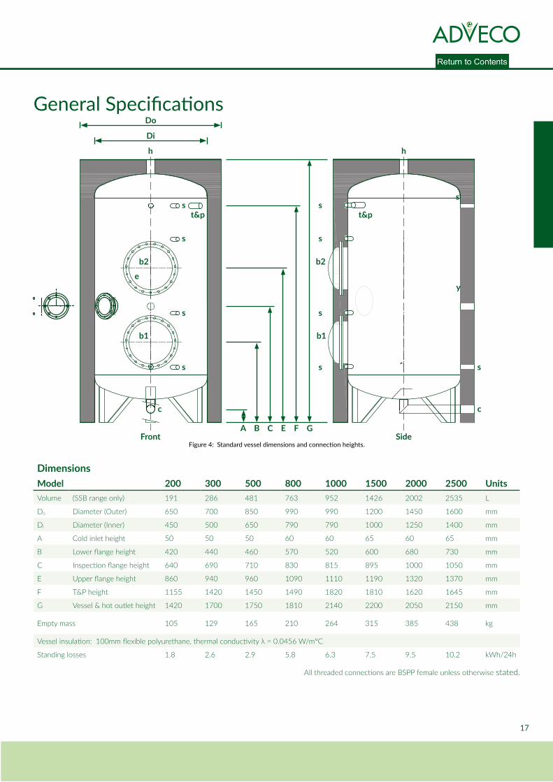
DimensionsModel 200 300 500 800 1000 1500 2000 2500 UnitsVolume (SSB range only) 191 286 481 763 952 1426 2002 2535 L
Do Diameter (Outer) 650 700 850 990 990 1200 1450 1600 mm
Di Diameter (Inner) 450 500 650 790 790 1000 1250 1400 mm
A Cold inlet height 50 50 50 60 60 65 60 65 mm
B Lower flange height 420 440 460 570 520 600 680 730 mm
C Inspection flange height 640 690 710 830 815 895 1000 1050 mm
E Upper flange height 860 940 960 1090 1110 1190 1320 1370 mm
F T&P height 1155 1420 1450 1490 1820 1810 1620 1645 mm
G Vessel & hot outlet height 1420 1700 1750 1810 2140 2200 2050 2150 mm
Empty mass 105 129 165 210 264 315 385 438 kg
Vessel insulation: 100mm flexible polyurethane, thermal conductivity λ = 0.0456 W/m°C
Standing losses 1.8 2.6 2.9 5.8 6.3 7.5 9.5 10.2 kWh/24h
All threaded connections are BSPP female unless otherwise stated.
Figure 4: Standard vessel dimensions and connection heights.
A B C E
h
s
y
c
h
c
s
s
s
s
s
s
st&p
e
t&p
s
s
b1
b2
b1
b2
Front Side
Di
Do
F G
P R A C T I C A L , E F F I C I E N T & S U S T A I N A B L E B U I L D I N G S E R V I C E S S O L U T I O N S
Stainless Steel SSB, SSI, SST range - Installation, Operation, and Maintenance Manual 18
Flange Specifications
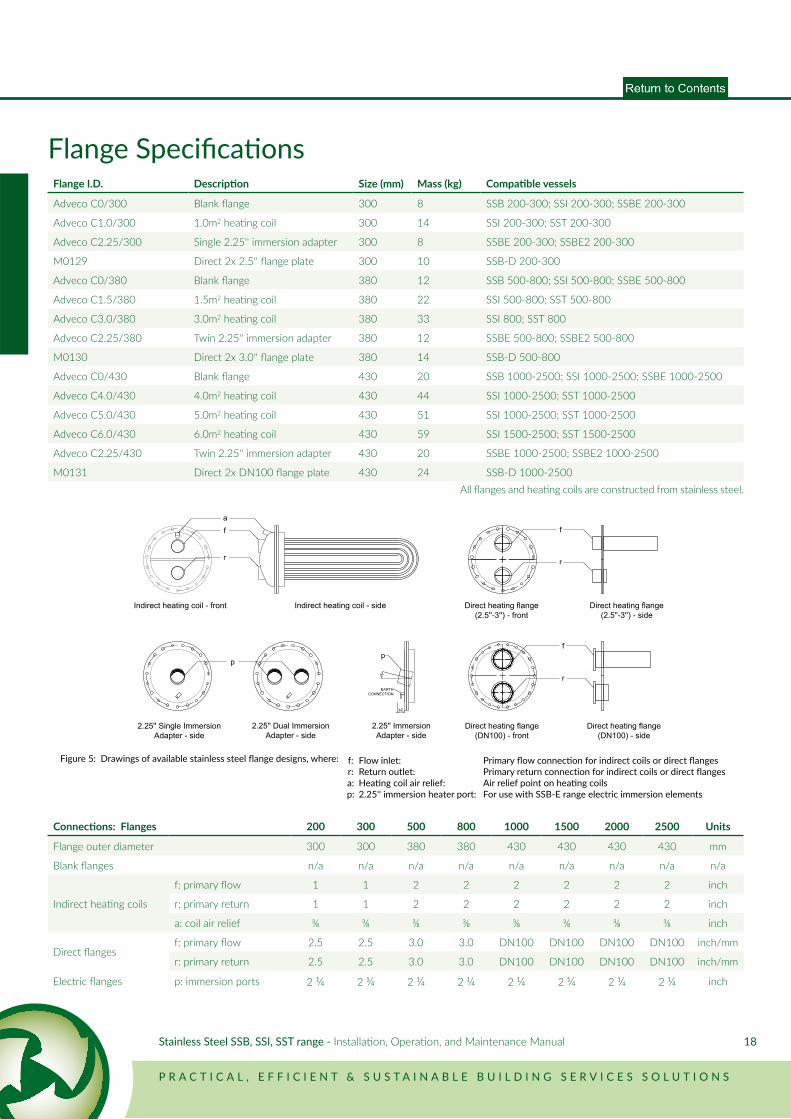
Connections: Flanges 200 300 500 800 1000 1500 2000 2500 Units
Flange outer diameter 300 300 380 380 430 430 430 430 mm
Blank flanges n/a n/a n/a n/a n/a n/a n/a n/a n/a
Indirect heating coils
f: primary flow 1 1 2 2 2 2 2 2 inch
r: primary return 1 1 2 2 2 2 2 2 inch
a: coil air relief ⅜ ⅜ ⅜ ⅜ ⅜ ⅜ ⅜ ⅜ inch
Direct flangesf: primary flow 2.5 2.5 3.0 3.0 DN100 DN100 DN100 DN100 inch/mm
r: primary return 2.5 2.5 3.0 3.0 DN100 DN100 DN100 DN100 inch/mm
Electric flanges p: immersion ports 2 ¼ 2 ¼ 2 ¼ 2 ¼ 2 ¼ 2 ¼ 2 ¼ 2 ¼ inch
Flange I.D. Description Size (mm) Mass (kg) Compatible vessels
Adveco C0/300 Blank flange 300 8 SSB 200-300; SSI 200-300; SSBE 200-300
Adveco C1.0/300 1.0m2 heating coil 300 14 SSI 200-300; SST 200-300
Adveco C2.25/300 Single 2.25'' immersion adapter 300 8 SSBE 200-300; SSBE2 200-300
M0129 Direct 2x 2.5'' flange plate 300 10 SSB-D 200-300
Adveco C0/380 Blank flange 380 12 SSB 500-800; SSI 500-800; SSBE 500-800
Adveco C1.5/380 1.5m2 heating coil 380 22 SSI 500-800; SST 500-800
Adveco C3.0/380 3.0m2 heating coil 380 33 SSI 800; SST 800
Adveco C2.25/380 Twin 2.25'' immersion adapter 380 12 SSBE 500-800; SSBE2 500-800
M0130 Direct 2x 3.0'' flange plate 380 14 SSB-D 500-800
Adveco C0/430 Blank flange 430 20 SSB 1000-2500; SSI 1000-2500; SSBE 1000-2500
Adveco C4.0/430 4.0m2 heating coil 430 44 SSI 1000-2500; SST 1000-2500
Adveco C5.0/430 5.0m2 heating coil 430 51 SSI 1000-2500; SST 1000-2500
Adveco C6.0/430 6.0m2 heating coil 430 59 SSI 1500-2500; SST 1500-2500
Adveco C2.25/430 Twin 2.25'' immersion adapter 430 20 SSBE 1000-2500; SSBE2 1000-2500
M0131 Direct 2x DN100 flange plate 430 24 SSB-D 1000-2500
15°
p
EARTHCONNECTION
42
Indirect heating coil - sideIndirect heating coil - front
2.25'' ImmersionAdapter - side
2.25'' Single ImmersionAdapter - side
2.25'' Dual ImmersionAdapter - side
Direct heating flange(2.5''-3'') - front
Direct heating flange(2.5''-3'') - side
Direct heating flange(DN100) - front
Direct heating flange(DN100) - side
f
r
a
p
f
r
f
r
All flanges and heating coils are constructed from stainless steel.
Figure 5: Drawings of available stainless steel flange designs, where: f: Flow inlet: Primary flow connection for indirect coils or direct flangesr: Return outlet: Primary return connection for indirect coils or direct flangesa: Heating coil air relief: Air relief point on heating coilsp: 2.25'' immersion heater port: For use with SSB-E range electric immersion elements
P R A C T I C A L , E F F I C I E N T & S U S T A I N A B L E B U I L D I N G S E R V I C E S S O L U T I O N S
Stainless Steel SSB, SSI, SST range - Installation, Operation, and Maintenance Manual 19
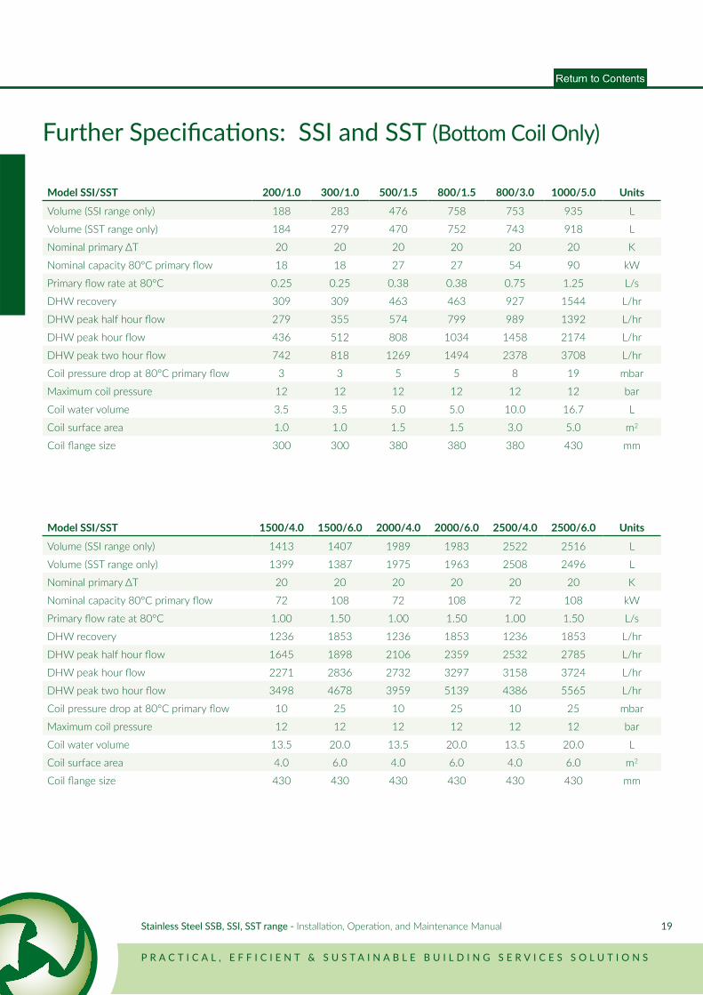
Further Specifications: SSI and SST (Bottom Coil Only)
Model SSI/SST 200/1.0 300/1.0 500/1.5 800/1.5 800/3.0 1000/5.0 Units
Volume (SSI range only) 188 283 476 758 753 935 L
Volume (SST range only) 184 279 470 752 743 918 L
Nominal primary ΔT 20 20 20 20 20 20 K
Nominal capacity 80°C primary flow 18 18 27 27 54 90 kW
Primary flow rate at 80°C 0.25 0.25 0.38 0.38 0.75 1.25 L/s
DHW recovery 309 309 463 463 927 1544 L/hr
DHW peak half hour flow 279 355 574 799 989 1392 L/hr
DHW peak hour flow 436 512 808 1034 1458 2174 L/hr
DHW peak two hour flow 742 818 1269 1494 2378 3708 L/hr
Coil pressure drop at 80°C primary flow 3 3 5 5 8 19 mbar
Maximum coil pressure 12 12 12 12 12 12 bar
Coil water volume 3.5 3.5 5.0 5.0 10.0 16.7 L
Coil surface area 1.0 1.0 1.5 1.5 3.0 5.0 m2
Coil flange size 300 300 380 380 380 430 mm
Model SSI/SST 1500/4.0 1500/6.0 2000/4.0 2000/6.0 2500/4.0 2500/6.0 Units
Volume (SSI range only) 1413 1407 1989 1983 2522 2516 L
Volume (SST range only) 1399 1387 1975 1963 2508 2496 L
Nominal primary ΔT 20 20 20 20 20 20 K
Nominal capacity 80°C primary flow 72 108 72 108 72 108 kW
Primary flow rate at 80°C 1.00 1.50 1.00 1.50 1.00 1.50 L/s
DHW recovery 1236 1853 1236 1853 1236 1853 L/hr
DHW peak half hour flow 1645 1898 2106 2359 2532 2785 L/hr
DHW peak hour flow 2271 2836 2732 3297 3158 3724 L/hr
DHW peak two hour flow 3498 4678 3959 5139 4386 5565 L/hr
Coil pressure drop at 80°C primary flow 10 25 10 25 10 25 mbar
Maximum coil pressure 12 12 12 12 12 12 bar
Coil water volume 13.5 20.0 13.5 20.0 13.5 20.0 L
Coil surface area 4.0 6.0 4.0 6.0 4.0 6.0 m2
Coil flange size 430 430 430 430 430 430 mm
20
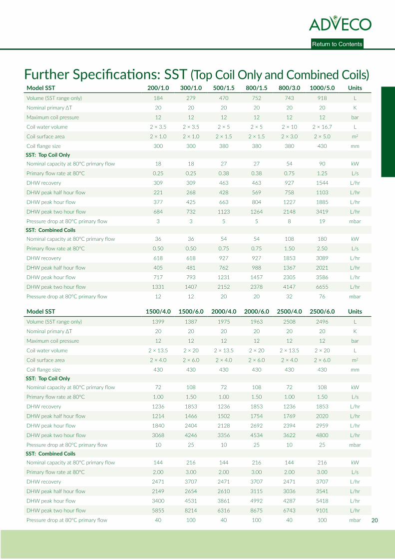
Model SST 200/1.0 300/1.0 500/1.5 800/1.5 800/3.0 1000/5.0 UnitsVolume (SST range only) 184 279 470 752 743 918 L
Nominal primary ΔT 20 20 20 20 20 20 K
Maximum coil pressure 12 12 12 12 12 12 bar
Coil water volume 2 × 3.5 2 × 3.5 2 × 5 2 × 5 2 × 10 2 × 16.7 L
Coil surface area 2 × 1.0 2 × 1.0 2 × 1.5 2 × 1.5 2 × 3.0 2 × 5.0 m2
Coil flange size 300 300 380 380 380 430 mm
SST: Top Coil OnlyNominal capacity at 80°C primary flow 18 18 27 27 54 90 kW
Primary flow rate at 80°C 0.25 0.25 0.38 0.38 0.75 1.25 L/s
DHW recovery 309 309 463 463 927 1544 L/hr
DHW peak half hour flow 221 268 428 569 758 1103 L/hr
DHW peak hour flow 377 425 663 804 1227 1885 L/hr
DHW peak two hour flow 684 732 1123 1264 2148 3419 L/hr
Pressure drop at 80°C primary flow 3 3 5 5 8 19 mbar
SST: Combined CoilsNominal capacity at 80°C primary flow 36 36 54 54 108 180 kW
Primary flow rate at 80°C 0.50 0.50 0.75 0.75 1.50 2.50 L/s
DHW recovery 618 618 927 927 1853 3089 L/hr
DHW peak half hour flow 405 481 762 988 1367 2021 L/hr
DHW peak hour flow 717 793 1231 1457 2305 3586 L/hr
DHW peak two hour flow 1331 1407 2152 2378 4147 6655 L/hr
Pressure drop at 80°C primary flow 12 12 20 20 32 76 mbar
Further Specifications: SST (Top Coil Only and Combined Coils)
Model SST 1500/4.0 1500/6.0 2000/4.0 2000/6.0 2500/4.0 2500/6.0 UnitsVolume (SST range only) 1399 1387 1975 1963 2508 2496 L
Nominal primary ΔT 20 20 20 20 20 20 K
Maximum coil pressure 12 12 12 12 12 12 bar
Coil water volume 2 × 13.5 2 × 20 2 × 13.5 2 × 20 2 × 13.5 2 × 20 L
Coil surface area 2 × 4.0 2 × 6.0 2 × 4.0 2 × 6.0 2 × 4.0 2 × 6.0 m2
Coil flange size 430 430 430 430 430 430 mm
SST: Top Coil OnlyNominal capacity at 80°C primary flow 72 108 72 108 72 108 kW
Primary flow rate at 80°C 1.00 1.50 1.00 1.50 1.00 1.50 L/s
DHW recovery 1236 1853 1236 1853 1236 1853 L/hr
DHW peak half hour flow 1214 1466 1502 1754 1769 2020 L/hr
DHW peak hour flow 1840 2404 2128 2692 2394 2959 L/hr
DHW peak two hour flow 3068 4246 3356 4534 3622 4800 L/hr
Pressure drop at 80°C primary flow 10 25 10 25 10 25 mbar
SST: Combined CoilsNominal capacity at 80°C primary flow 144 216 144 216 144 216 kW
Primary flow rate at 80°C 2.00 3.00 2.00 3.00 2.00 3.00 L/s
DHW recovery 2471 3707 2471 3707 2471 3707 L/hr
DHW peak half hour flow 2149 2654 2610 3115 3036 3541 L/hr
DHW peak hour flow 3400 4531 3861 4992 4287 5418 L/hr
DHW peak two hour flow 5855 8214 6316 8675 6743 9101 L/hr
Pressure drop at 80°C primary flow 40 100 40 100 40 100 mbar
21
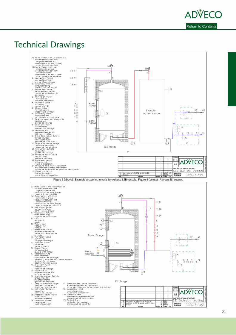
Technical Drawings
Figure 5 (above): Example system schematic for Adveco SSB vessels. Figure 6 (below): Adveco SSI vessels.
P R A C T I C A L , E F F I C I E N T & S U S T A I N A B L E B U I L D I N G S E R V I C E S S O L U T I O N S
Stainless Steel SSB, SSI, SST range - Installation, Operation, and Maintenance Manual 22
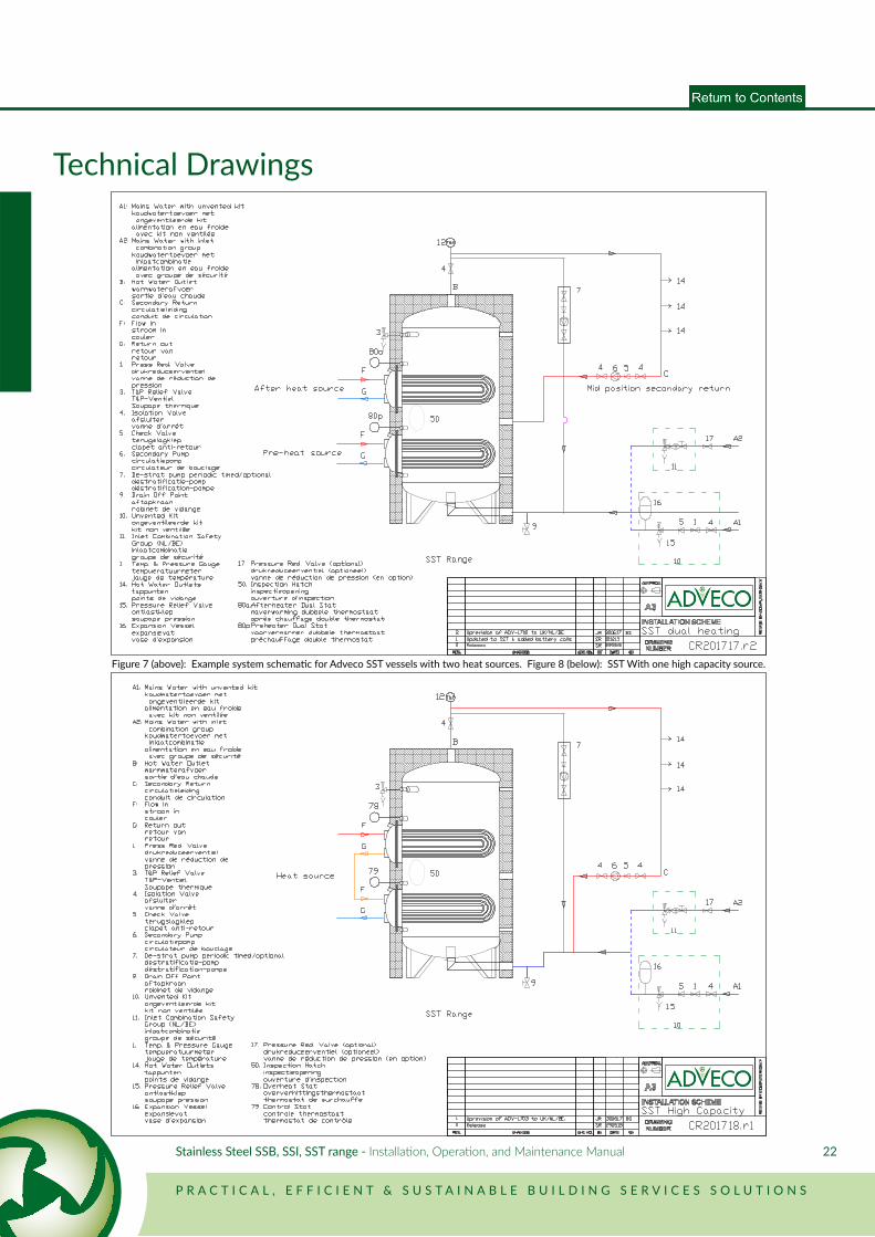
Technical Drawings
Figure 7 (above): Example system schematic for Adveco SST vessels with two heat sources. Figure 8 (below): SST With one high capacity source.
23
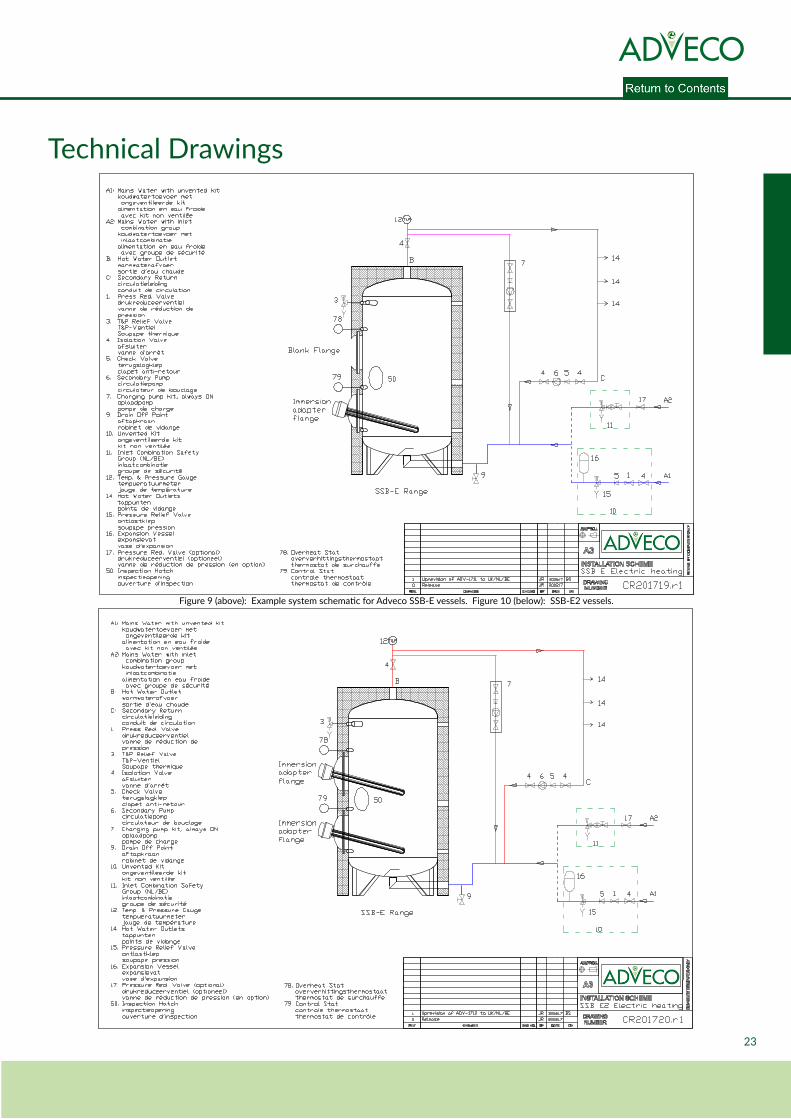
Technical Drawings
Figure 9 (above): Example system schematic for Adveco SSB-E vessels. Figure 10 (below): SSB-E2 vessels.
P R A C T I C A L , E F F I C I E N T & S U S T A I N A B L E B U I L D I N G S E R V I C E S S O L U T I O N S
Stainless Steel SSB, SSI, SST range - Installation, Operation, and Maintenance Manual 24
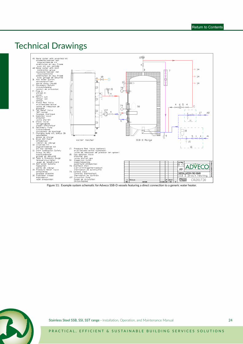
Technical Drawings
Figure 11: Example system schematic for Adveco SSB-D vessels featuring a direct connection to a generic water heater.
25
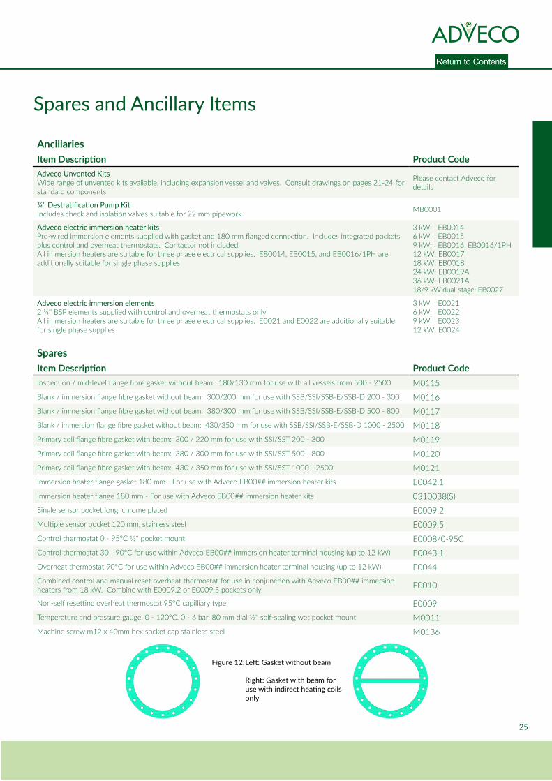
Spares and Ancillary Items
AncillariesItem Description Product CodeAdveco Unvented KitsWide range of unvented kits available, including expansion vessel and valves. Consult drawings on pages 21-24 for standard components
Please contact Adveco for details
¾'' Destratification Pump KitIncludes check and isolation valves suitable for 22 mm pipework MB0001
Adveco electric immersion heater kitsPre-wired immersion elements supplied with gasket and 180 mm flanged connection. Includes integrated pockets plus control and overheat thermostats. Contactor not included.All immersion heaters are suitable for three phase electrical supplies. EB0014, EB0015, and EB0016/1PH are additionally suitable for single phase supplies
3 kW: EB00146 kW: EB00159 kW: EB0016, EB0016/1PH12 kW: EB001718 kW: EB001824 kW: EB0019A36 kW: EB0021A18/9 kW dual-stage: EB0027
Adveco electric immersion elements2 ¼'' BSP elements supplied with control and overheat thermostats onlyAll immersion heaters are suitable for three phase electrical supplies. E0021 and E0022 are additionally suitable for single phase supplies
3 kW: E00216 kW: E00229 kW: E002312 kW: E0024
SparesItem Description Product CodeInspection / mid-level flange fibre gasket without beam: 180/130 mm for use with all vessels from 500 - 2500 M0115Blank / immersion flange fibre gasket without beam: 300/200 mm for use with SSB/SSI/SSB-E/SSB-D 200 - 300 M0116Blank / immersion flange fibre gasket without beam: 380/300 mm for use with SSB/SSI/SSB-E/SSB-D 500 - 800 M0117Blank / immersion flange fibre gasket without beam: 430/350 mm for use with SSB/SSI/SSB-E/SSB-D 1000 - 2500 M0118Primary coil flange fibre gasket with beam: 300 / 220 mm for use with SSI/SST 200 - 300 M0119Primary coil flange fibre gasket with beam: 380 / 300 mm for use with SSI/SST 500 - 800 M0120Primary coil flange fibre gasket with beam: 430 / 350 mm for use with SSI/SST 1000 - 2500 M0121Immersion heater flange gasket 180 mm - For use with Adveco EB00## immersion heater kits E0042.1Immersion heater flange 180 mm - For use with Adveco EB00## immersion heater kits 0310038(S)Single sensor pocket long, chrome plated E0009.2Multiple sensor pocket 120 mm, stainless steel E0009.5Control thermostat 0 - 95°C 1/2'' pocket mount E0008/0-95CControl thermostat 30 - 90°C for use within Adveco EB00## immersion heater terminal housing (up to 12 kW) E0043.1Overheat thermostat 90°C for use within Adveco EB00## immersion heater terminal housing (up to 12 kW) E0044Combined control and manual reset overheat thermostat for use in conjunction with Adveco EB00## immersion heaters from 18 kW. Combine with E0009.2 or E0009.5 pockets only. E0010
Non-self resetting overheat thermostat 95°C capilliary type E0009Temperature and pressure gauge, 0 - 120°C. 0 - 6 bar, 80 mm dial 1/2'' self-sealing wet pocket mount M0011Machine screw m12 x 40mm hex socket cap stainless steel M0136
Figure 12: Left: Gasket without beam
Right: Gasket with beam for use with indirect heating coils only
P R A C T I C A L , E F F I C I E N T & S U S T A I N A B L E B U I L D I N G S E R V I C E S S O L U T I O N S
Stainless Steel SSB, SSI, SST range - Installation, Operation, and Maintenance Manual 26
Contact Details & Warranty InformationThe Adveco SSB, SSI, SST range, this manual, and all information contained within, are supplied by Adveco Ltd.
UKAdveco Ltd. Unit 7&8 Armstrong Mall, Southwood Business Park, Farnborough, Hampshire, GU14 0NR
T: 01252 551 540 [email protected] www.adveco.co
The Adveco SSB, SSI, SST range is provided with a 5 year vessel warranty reliant upon the following conditions: • The vessel is correctly and safely stored, installed, and used as instructed by this manual. • The vessel is filled exclusively with potable water. • The domestic hot water system is kept in a good condition and is suitably maintained, inclusive of maintenance of the vessel as directed on page 16 of this manual. • The vessel has not been altered, tampered with, and has not been subjected to damage from frost, vacuum, or external influence.
Exclusions to warranty conditions include: • Consequential damage arising from malfunction, failure, or leaks associated with the vessel. • Failure or damage of the vessel or domestic hot water system arising from the build up of excessive scale. • Any parts and labour charges associated with maintenance, repair, or replacement of the vessel.
For further information and warranty claims, please contact Adveco Ltd. through the address listed above.
Adveco Sales Department Adveco Spares DepartmentT: 01252 551 540 Option 1 T: 01252 551 540 Option 3E: [email protected] E: [email protected]
Adveco Technical Department Adveco Design DepartmentT: 01252 551 540 Option 4 T: 01252 551 540 Option 5E: [email protected] E: [email protected]
Adveco Service & Commissioning DepartmentT: 01252 551 540 Option 6E: [email protected]
27
Notes
P R A C T I C A L , E F F I C I E N T & S U S T A I N A B L E B U I L D I N G S E R V I C E S S O L U T I O N S
Adveco Ltd. Unit 7&8 Armstrong Mall, Southwood Business Park, Farnborough, Hampshire GU14 0NR Company Reg : 09493966 T : 01252 551 540 E : [email protected] I : www.adveco.co
Adveco also offer the following products and services:
• Bespoke system design • Maintenance and service packages • Buffer tanks • Indirect and direct hot water systems • Off site manufacturing of skids and plant rooms
• Controls Systems • Packaged plate heat exchangers • Solar thermal systems • Gas fired heating systems • Combined heat & power cogeneration systems