Embed Size (px)
Citation preview

Product Manual
STAC MANUAL
AboUT CoMrex 6
WArrANTy ANd diSCLAiMer 6
CopyrighT NoTiCe 6
i. iNTrodUCTioN 7
STAC FeATUreS 7
WhAT CoMeS WiTh STAC 7
ii. MAiNFrAMe diAgrAMS ANd iNSTALLATioN 8
phoNe LiNe CoNNeCTioNS 9
phoNe LiNe piNoUTS 10
xLr piNoUTS 10
dip SWiTCheS 12
iii. CoNTroL SUrFACe diAgrAMS ANd iNSTALLATioN 14
bASiCS 14
CoNFigUrATioN 16
dip SWiTCh SeTTiNgS 17
More AboUT The AUx/NexT bUTToN ANd CoNTACT CLoSUreS 17
iV. CoNTroL SUrFACe operATioN 19
SCreeNer CoNTroL SUrFACe 19
TypiCAL SCreeNer operATioN 19
STUdio CoNTroL SUrFACe 20
TypiCAL STUdio operATioN 20
oTher CoNTroL SUrFACe iNdiCATioNS 21hoLd 21oN Air 21prioriTy 21AUTo ATTeNdANT 21
V. STAC ip 23
AboUT STAC ip 23
SeTUp 23
reqUireMeNTS 23
ip AddreSS CoNFigUrATioN 23
STATiC VS. dyNAMiC ip AddreSSiNg 24
dyNAMiC CoNFigUrATioN 24
STATiC CoNFigUrATioN 24
gAiNiNg ACCeSS 25
STAC ip iNTerFACe 25
MAjor STAC ip FUNCTioNS 26
bUTToN STATUS 28
USiNg STAC ip WiThoUT A MoUSe 28
iNdiVidUAL LiNe CoMMANdS 29
gLobAL CoMMANdS 29
eSCApiNg CoMMANd Mode preMATUreLy 29
oTher FUNCTioNS 29
ASSoCiATiNg STAC ip WiTh A CoNTroL SUrFACe 30
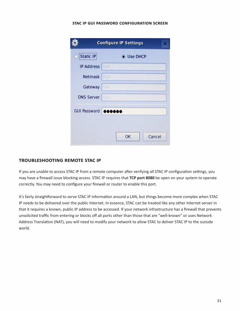
ChANgiNg The STAC ip pASSWord 30
TroUbLeShooTiNg reMoTe STAC ip 31
deLiVeriNg STAC ip oUTSide The LAN eNViroNMeNT 32
Vi. STAC hybrid SeTUp ANd operATioN 33
STAC bLoCK diAgrAM 33
AboUT hybridS iN geNerAL 33
AboUT The STAC hybridS 34
TeLephoNe SepArATioN/NULL 34
AUToMATiC gAiN CoNTroL 35
AUToMATiC Mix-MiNUS 35
CALLer CoNTroL 35
AboUT Mix-MiNUS 35
bUiLdiNg A Mix-MiNUS 36
opTioN A - CoNSoLe proVideS TeLephoNe bUS or AUdiTioN bUS 37
opTioN b - CoNSoLe proVideS Mix-MiNUS ModULe For SeLeCT ChANNeLS 39
opTioN C - CoNNeCTioN oF AN exTerNAL hybrid To proVide TWo iNpUT porTS 40
opTioN d - No AUx bUS or Mix-MiNUS ModULe AVAiLAbLe 41
opTioN e - USiNg AUTo Mix-MiNUS FeATUre 42
TriM poTS 43
Vii. iNdiVidUAL LiNe CoNFigUrATioN ANd CLUSTeriNg 44
iNTrodUCTioN 44
ACCeSSiNg LiNe SeTTiNgS 44
LiNe CoNFigUrATioN 44
LiNe CLUSTeriNg 46
CoNFigUriNg LiNe CLUSTeriNg 46
CLUSTeriNg operATioN 47
Viii. AppeNdix A - CoNForMiTy ANd regULATory iNForMATioN 48
SUppLier’S deCLArATioN oF CoNForMiTy 48
deCLArATioN oF CoNForMiTy For TerMiNAL eqUipMeNT - iN ACCordANCe WiTh iSo/ieC gUide 22 49
eC deCLArATioN oF CoNForMiTy For r&TTe direCTiVe 50
regULATory iNForMATioN 51
ix. AppeNdix b - CoNNeCTiNg AN exTerNAL hybrid To STAC 52
x. AppeNdix C - CreATiNg A prodUCTioN/NeWS exTeNSioN To STAC 56
iNTrodUCTioN 56
reqUireMeNTS 56
CoNNeCTioN 56
operATioN 57

AboUT CoMrex
Comrex has been building reliable, high quality broadcast equipment since 1961. Our products are used daily in every part of the world by networks, stations and program producers.
Every product we manufacture has been carefully designed to function flawlessly, under the harshest conditions, over many years of use. Each unit we ship has been individually and thoroughly tested.
Comrex stands behind its products. We promise that if you call us for technical assistance, you will talk directly with someone who knows about the equipment and will do everything possible to help you.
You can contact Comrex by phone at 978-784-1776. Our toll free number in North America is 800-237-1776. Product information along with engineering notes and user reports are available on our website at www.comrex.com. Our email address is [email protected].
WArrANTy ANd diSCLAiMer
All equipment manufactured by Comrex Corporation is warranted by Comrex against defects in material and workmanship for one year from the date of original purchase, as verified by the return of the Warranty Registration Card. During the warranty period, we will repair or, at our option, replace at no charge a product that proves to be defective, provided you obtain return authorization from Comrex and return the product, shipping prepaid, to Comrex Corporation, 19 Pine Road, Devens, MA 01434 USA. For return authorization, contact Comrex at 978-784-1776 or fax 978-784-1717.
This Warranty does not apply if the product has been damaged by accident or misuse or as the result of service or modification performed by anyone other than Comrex Corporation.
With the exception of the warranties set forth above, Comrex Corporation makes no other warranties, expressed or implied or statutory, including but not limited to warranties of merchantability and fitness for a particular purpose, which are hereby expressly disclaimed. In no event shall Comrex Corporation have any liability for indirect, conse-quential or punitive damages resulting from the use of this product.
CopyrighT NoTiCe
The Comrex proprietary code and licensed, third party proprietary code residing in and otherwise associated with this product are protected by copyright law and international treaties. Unauthorized reproduction or distribution of this product, or any portion of it, may result in civil and criminal sanctions, and will be prosecuted to the fullest extent of the law.
US Government Restricted Rights - Use, duplication, or disclosure by the US Government is subject to restrictions set forth
in subparagraph (c)(1)(ii) of the Rights in Technical Data and Computer Software clause at DFARS (48 CFR) 252.227-7013 or
subparagraphs (c)(1) and (2) of the Commercial Computer Software-Restricted Rights clause at FAR (48 CFR) 52.227-19, as
applicable.

7
i. iNTrodUCTioN
STAC FeATUreS
Comrex STAC (Studio Telephone Access Center) is a multiline on-air telephone system, available for six lines (STAC6) or twelve lines (STAC12). Both versions offer the following features:
• Intuitive, attractive control surfaces with built-in handsets for call screening.
• Mainframe containing two state-of-the-art digital telephone hybrids for natural-sounding caller audio.
• Control surfaces, up to four per system, configurable for Screener or Studio functions.
• All telco and control surface connections via UTP cable and RJ-45 connectors.
• Self-powered control surfaces.
• Telephone line Loop-Thru access.
• Auto-answer and auto-disconnect of phone lines.
• Auto Attendant answers lines and plays your pre-recorded message to caller.
• STAC IP allows mainframe to be used as server for remote control functions.
• STAC IP delivers web page for remote control.
• Shares and transfers lines between multiple STACs.
WhAT CoMeS WiTh STAC
The following items are shipped with a new STAC System:
(1) STAC mainframe with one or two six-line telco cards*
(1) STAC control surface (with sidecar for twelve-line operation)
(1) AC power cord for mainframe
(1) RJ-45 cable for control surface
(1) Operating manual
(1) Warranty card (Please fill out and return.)
*The STAC system is delivered as a six or twelve-line model. A six-line STAC (STAC6) can be upgraded to a twelve-line STAC (STAC12) with one additional telco board and a sidecar for the control surface to allow line control for six more lines.
8
ii. MAiNFrAMe diAgrAMS ANd iNSTALLATioN
1
2
3 4 5 6
9 10 11 12
14
1716
18
1513
197 8
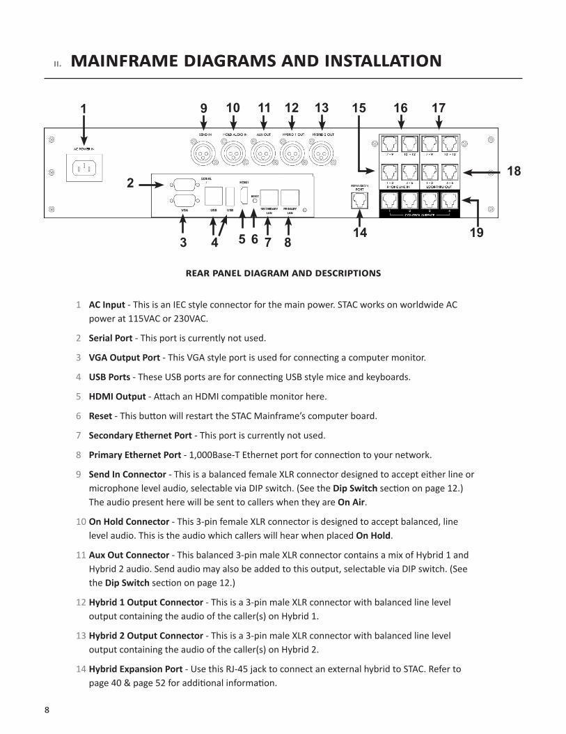
reAr pANeL diAgrAM ANd deSCripTioNS
1 AC Input - This is an IEC style connector for the main power. STAC works on worldwide AC power at 115VAC or 230VAC.
2 Serial Port - This port is currently not used.
3 VGA Output Port - This VGA style port is used for connecting a computer monitor.
4 USB Ports - These USB ports are for connecting USB style mice and keyboards.
5 HDMI Output - Attach an HDMI compatible monitor here.
6 Reset - This button will restart the STAC Mainframe’s computer board.
7 Secondary Ethernet Port - This port is currently not used.
8 Primary Ethernet Port - 1,000Base-T Ethernet port for connection to your network.
9 Send In Connector - This is a balanced female XLR connector designed to accept either line or microphone level audio, selectable via DIP switch. (See the Dip Switch section on page 12.) The audio present here will be sent to callers when they are On Air.
10 On Hold Connector - This 3-pin female XLR connector is designed to accept balanced, line level audio. This is the audio which callers will hear when placed On Hold.
11 Aux Out Connector - This balanced 3-pin male XLR connector contains a mix of Hybrid 1 and Hybrid 2 audio. Send audio may also be added to this output, selectable via DIP switch. (See the Dip Switch section on page 12.)
12 Hybrid 1 Output Connector - This is a 3-pin male XLR connector with balanced line level output containing the audio of the caller(s) on Hybrid 1.
13 Hybrid 2 Output Connector - This is a 3-pin male XLR connector with balanced line level output containing the audio of the caller(s) on Hybrid 2.
14 Hybrid Expansion Port - Use this RJ-45 jack to connect an external hybrid to STAC. Refer to page 40 & page 52 for additional information.
9
15 & 16 Phones Lines - These four RJ-45 jacks provide connection of telephone lines 1-6 and 7-12 to the mainframe. See the Phone Line Pinouts section on page 10 for wiring instructions.
17 & 18 Loop-Thru - These four RJ-45 jacks provide optional Loop-Thru connections for telephone lines 1-6 and 7-12, allowing access to designated telephone lines when STAC is not using them. STAC can also be configured via DIP switches to disable line access when a Loop-Thru device is active on that line. (See the Dip Switch section on page 12.)
Note: A STAC6 System only has phone line and Loop-Thru functions for lines 1-6.
19 Control Surface Jacks - Use these RJ-45 jacks to connect up to four control surfaces to the mainframe with standard four-pair cable (Cat-4 or better).
phoNe LiNe CoNNeCTioNS
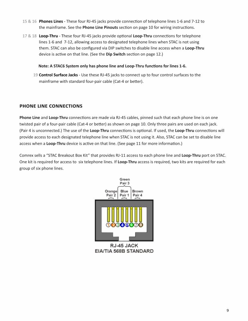
Phone Line and Loop-Thru connections are made via RJ-45 cables, pinned such that each phone line is on one twisted pair of a four-pair cable (Cat-4 or better) as shown on page 10. Only three pairs are used on each jack. (Pair 4 is unconnected.) The use of the Loop-Thru connections is optional. If used, the Loop-Thru connections will provide access to each designated telephone line when STAC is not using it. Also, STAC can be set to disable line access when a Loop-Thru device is active on that line. (See page 11 for more information.)
Comrex sells a “STAC Breakout Box Kit” that provides RJ-11 access to each phone line and Loop-Thru port on STAC. One kit is required for access to six telephone lines. If Loop-Thru access is required, two kits are required for each group of six phone lines.
10
phoNe LiNe piNoUTS
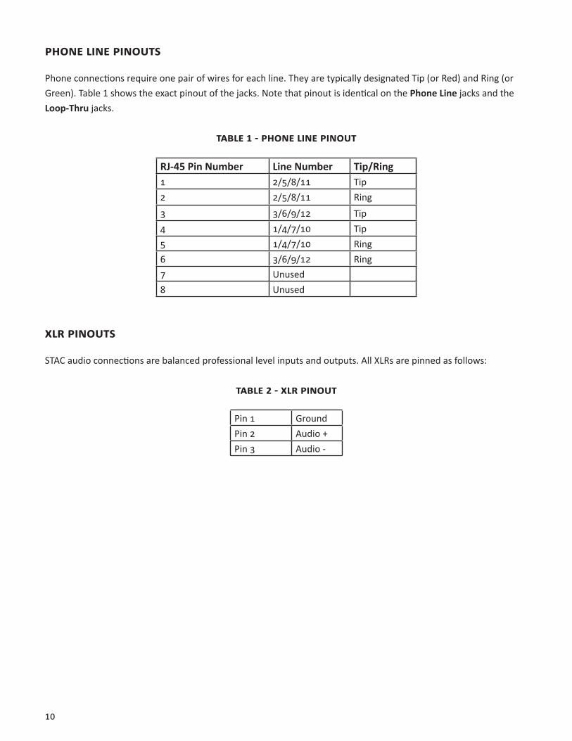
Phone connections require one pair of wires for each line. They are typically designated Tip (or Red) and Ring (or Green). Table 1 shows the exact pinout of the jacks. Note that pinout is identical on the Phone Line jacks and the Loop-Thru jacks.
TAbLe 1 - phoNe LiNe piNoUT
RJ-45 Pin Number Line Number Tip/Ring1 2/5/8/11 Tip2 2/5/8/11 Ring3 3/6/9/12 Tip4 1/4/7/10 Tip5 1/4/7/10 Ring6 3/6/9/12 Ring7 Unused8 Unused
xLr piNoUTS
STAC audio connections are balanced professional level inputs and outputs. All XLRs are pinned as follows:
TAbLe 2 - xLr piNoUT
Pin 1 GroundPin 2 Audio +Pin 3 Audio -
11
FroNT pANeL diAgrAM ANd deSCripTioNS
INPUT HYBRID 1 HYBRID 2
1 2 3 4 5 6 7 8
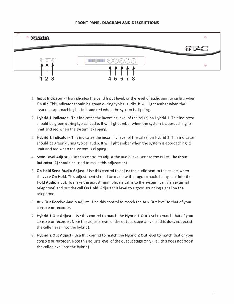
1 Input Indicator - This indicates the Send Input level, or the level of audio sent to callers when On Air. This indicator should be green during typical audio. It will light amber when the system is approaching its limit and red when the system is clipping.
2 Hybrid 1 Indicator - This indicates the incoming level of the call(s) on Hybrid 1. This indicator should be green during typical audio. It will light amber when the system is approaching its limit and red when the system is clipping.
3 Hybrid 2 Indicator - This indicates the incoming level of the call(s) on Hybrid 2. This indicator should be green during typical audio. It will light amber when the system is approaching its limit and red when the system is clipping.
4 Send Level Adjust - Use this control to adjust the audio level sent to the caller. The Input Indicator (1) should be used to make this adjustment.
5 On Hold Send Audio Adjust - Use this control to adjust the audio sent to the callers when they are On Hold. This adjustment should be made with program audio being sent into the Hold Audio input. To make the adjustment, place a call into the system (using an external telephone) and put the call On Hold. Adjust this level to a good sounding signal on the telephone.
6 Aux Out Receive Audio Adjust - Use this control to match the Aux Out level to that of your console or recorder.
7 Hybrid 1 Out Adjust - Use this control to match the Hybrid 1 Out level to match that of your console or recorder. Note this adjusts level of the output stage only (i.e. this does not boost the caller level into the hybrid).
8 Hybrid 2 Out Adjust - Use this control to match the Hybrid 2 Out level to match that of your console or recorder. Note this adjusts level of the output stage only (I.e., this does not boost the caller level into the hybrid).
12
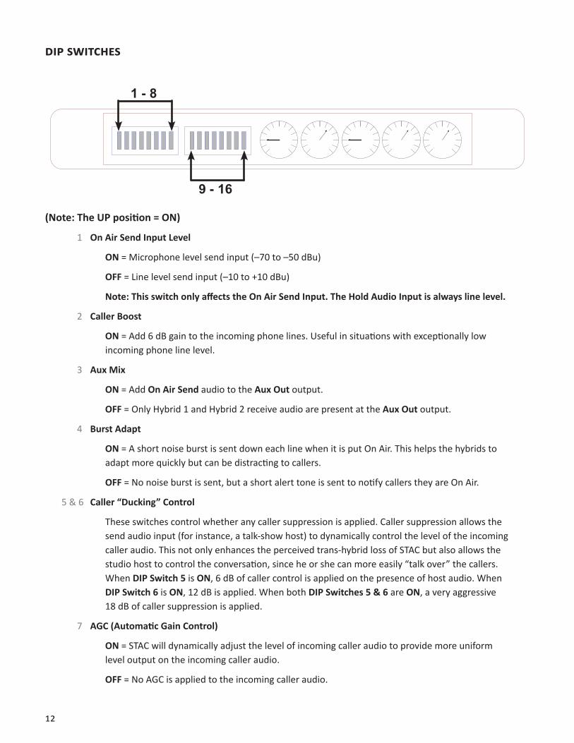
dip SWiTCheS
1 - 8
9 - 16
(Note: The UP position = ON)
1 On Air Send Input Level
ON = Microphone level send input (–70 to –50 dBu)
OFF = Line level send input (–10 to +10 dBu)
Note: This switch only affects the On Air Send Input. The Hold Audio Input is always line level.
2 Caller Boost
ON = Add 6 dB gain to the incoming phone lines. Useful in situations with exceptionally low incoming phone line level.
3 Aux Mix
ON = Add On Air Send audio to the Aux Out output.
OFF = Only Hybrid 1 and Hybrid 2 receive audio are present at the Aux Out output.
4 Burst Adapt
ON = A short noise burst is sent down each line when it is put On Air. This helps the hybrids to adapt more quickly but can be distracting to callers.
OFF = No noise burst is sent, but a short alert tone is sent to notify callers they are On Air.
5 & 6 Caller “Ducking” Control
These switches control whether any caller suppression is applied. Caller suppression allows the send audio input (for instance, a talk-show host) to dynamically control the level of the incoming caller audio. This not only enhances the perceived trans-hybrid loss of STAC but also allows the studio host to control the conversation, since he or she can more easily “talk over” the callers. When DIP Switch 5 is ON, 6 dB of caller control is applied on the presence of host audio. When DIP Switch 6 is ON, 12 dB is applied. When both DIP Switches 5 & 6 are ON, a very aggressive 18 dB of caller suppression is applied.
7 AGC (Automatic Gain Control)
ON = STAC will dynamically adjust the level of incoming caller audio to provide more uniform level output on the incoming caller audio.
OFF = No AGC is applied to the incoming caller audio.

13
8 Auto Mix-Minus
See the Using Auto Mix-Minus section on page 35 for a description of this function. Most applications should leave this switch set OFF.
9 VIP/Hotline Mode
ON = VIP/Hotline Mode is enabled for those lines that have been selected for this mode in the Line Configuration menu. These lines are removed from the Priority Queue and the Auto Attendant will be disabled. For further details see the Line Configuration section page 44.
OFF = All lines will participate in the Priority Queue and Auto Attendant functions even though they have been selected for VIP/Hotline Mode in the Line Configuration menu.
10 Auto Attendant 2/6 Rings
ON = Auto Attendant will answer incoming calls on the sixth ring.
OFF = Auto Attendant will answer incoming calls on the second ring.
11 Loop-Thru Sense Disable
ON = Loop-Thru sensing is ignored.
OFF = Loop-Thru sensing is enabled. When enabled, this function disables access to phone lines that have been picked up downstream of STAC. “Downstream” devices are those connected via the telephone line Loop-Thru ports on STAC. When this function is enabled, a downstream device going off-hook will be indicated by a special light sequence on the control surfaces, and those lines will be disabled on STAC until the downstream device goes on-hook.
Note: When the STAC has taken a line “off hook”, it is always disabled at the Loop-Thru jack.
12 Auto Disconnect Disable
ON = Lines must be dropped manually by control surfaces or STAC IP.
OFF = Lines will drop on sensing of momentary break in battery voltage (calling party disconnect signal).
13 Future
For future use.
14 Split Studio Mode
ON = Changes the Hybrid call assignment sequence required for Split Studio Mode. See page page 52 for details.
OFF = Default Hybrid call assignment of 1-2-2-1.
15 & 16 Future
For future use.
14
iii. CoNTroL SUrFACe diAgrAMS ANd iNSTALLATioN
bASiCS
STAC is delivered with one control surface. Four ports are present on the STAC mainframe, so up to four control surfaces may be used. Additional control surfaces are available from Comrex. Each control surface contains one telephone handset, useful for screening or dialing calls. The control surfaces require Cat-4 (or better) wiring with Ethernet style pinning, using all four pairs on the RJ-45 cable. Avoid underpinned and cross-over cables. The control surfaces are powered over this cable and can be extended to 100 feet.
Before setting up a control surface for use with STAC, you must determine whether the surface will be used as a Screener or a Studio surface. The major differences are listed below:
5 Only Studio control surfaces can put calls On Air.
6 Only Studio control surfaces provide indication of which hybrid is being used for each call.
7 Studio control surfaces share a single button for Answer and On Hold.
8 Screener surfaces have separate buttons for Answer and On Hold.
9 Studio and Screener surfaces have different color lights to indicate the various states of each phone line.
If you plan on using only one control surface (without STAC IP), you must configure the surface for Studio, since this will be the only way to put calls On Air. Studio surfaces can perform all functions of Screener surfaces.Used to screen incoming calls and to make outgoing calls.
15
Top VieW diAgrAM ANd deSCripTioNS
1
23 4 5 6
78
9
10
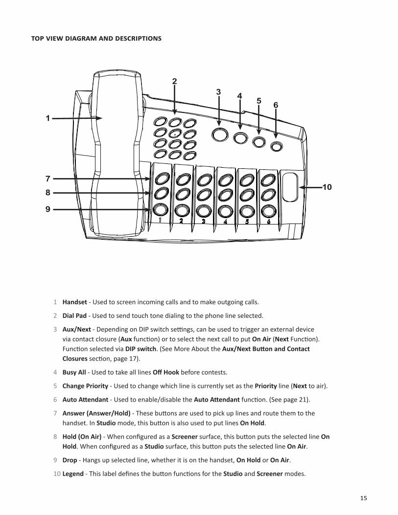
1 Handset - Used to screen incoming calls and to make outgoing calls.
2 Dial Pad - Used to send touch tone dialing to the phone line selected.
3 Aux/Next - Depending on DIP switch settings, can be used to trigger an external device via contact closure (Aux function) or to select the next call to put On Air (Next Function). Function selected via DIP switch. (See More About the Aux/Next Button and Contact Closures section, page 17).
4 Busy All - Used to take all lines Off Hook before contests.
5 Change Priority - Used to change which line is currently set as the Priority line (Next to air).
6 Auto Attendant - Used to enable/disable the Auto Attendant function. (See page 21).
7 Answer (Answer/Hold) - These buttons are used to pick up lines and route them to the handset. In Studio mode, this button is also used to put lines On Hold.
8 Hold (On Air) - When configured as a Screener surface, this button puts the selected line On Hold. When configured as a Studio surface, this button puts the selected line On Air.
9 Drop - Hangs up selected line, whether it is on the handset, On Hold or On Air.
10 Legend - This label defines the button functions for the Studio and Screener modes.
16
reAr VieW diAgrAM ANd deSCripTioNS
11
12 13
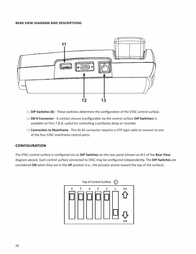
11 DIP Switches (6) - These switches determine the configuration of the STAC control surface.
12 DB-9 Connector - A contact closure (configurable via the control surface DIP Switches) is available on Pins 7 & 8, useful for controlling a profanity delay or recorder.
13 Connection to Mainframe - This RJ-45 connector requires a UTP type cable to connect to one of the four STAC mainframe control ports.
CoNFigUrATioN
The STAC control surface is configured via six DIP Switches on the rear panel (shown as #11 of the Rear View diagram above). Each control surface connected to STAC may be configured independently. The DIP Switches are considered ON when they are in the UP position (I.e., the actuator points toward the top of the surface).
17
dip SWiTCh SeTTiNgS
The DIP Switches have the following functions:
1 Screener/Studio Surface
ON = Screener surface.
OFF = Studio surface.
STAC control surfaces are provided with a removable and reversible legend that shows the functions of the line buttons in each of the two available modes. Make sure the legend follows the setting for DIP Switch 1.
2 & 3 Aux/Next Button & Contact Closures - Configure Aux/Next Button and DB-9 Contact Closure pins on control surface.
Note: For a full description of the Next and Aux functions and Contact Closures, see below.
4 & 5 For Future Use
6 Handset Boost
ON = Handset audio level normal.
OFF = Handset audio increased by 6 dB (for hearing impaired).
Note: The default settings for a control surface (as shipped from the factory) are DIP Switches 2,3,4,5,6 ON and DIP Switch 1 OFF.
More AboUT The AUx/NexT bUTToN ANd CoNTACT CLoSUreS
The Aux/Next button has several functions which are controlled by the settings of DIP Switches 2 & 3 on the control surface. The configuration of these DIP Switches also alters the Contact Closure function (available on Pins 7 & 8 of the control surface DB-9 connector).
Essentially, the button can trigger the contact closure directly (Aux Mode) either in momentary or latching fashion. Alternatively, the button can put the priority line to air (Next Mode).
Note: You cannot manually control the contact closure while using the Next Mode.
While in Next Mode, the contact closure on the control surface works differently. It provides a status indication that can be configured to close when any line is On Air (Record trigger) or when any line is Ringing (Line Ringing Indicator).
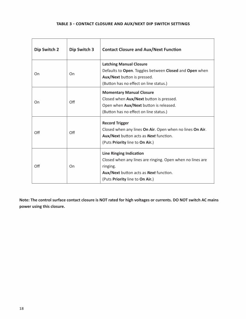
Table 3 on page 18 shows the DIP Switch configuration for each mode. DIP Switches are ON when they are up (actuator points to the top of the control surface).
18
TAbLe 3 - CoNTACT CLoSUre ANd AUx/NexT dip SWiTCh SeTTiNgS
Dip Switch 2 Dip Switch 3 Contact Closure and Aux/Next Function
On On
Latching Manual ClosureDefaults to Open. Toggles between Closed and Open when Aux/Next button is pressed. (Button has no effect on line status.)
On Off
Momentary Manual ClosureClosed when Aux/Next button is pressed. Open when Aux/Next button is released. (Button has no effect on line status.)
Off Off
Record TriggerClosed when any lines On Air. Open when no lines On Air.Aux/Next button acts as Next function.(Puts Priority line to On Air.)
Off On
Line Ringing IndicationClosed when any lines are ringing. Open when no lines are ringing.Aux/Next button acts as Next function.(Puts Priority line to On Air.)
Note: The control surface contact closure is NOT rated for high voltages or currents. DO NOT switch AC mains power using this closure.
19
iV. CoNTroL SUrFACe operATioN
SCreeNer CoNTroL SUrFACe
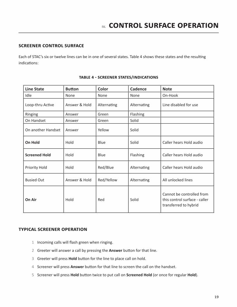
Each of STAC’s six or twelve lines can be in one of several states. Table 4 shows these states and the resulting indications:
TAbLe 4 - SCreeNer STATeS/iNdiCATioNS
Line State Button Color Cadence NoteIdle None None None On-Hook
Loop-thru Active Answer & Hold Alternating Alternating Line disabled for use
Ringing Answer Green FlashingOn Handset Answer Green Solid
On another Handset Answer Yellow Solid
On Hold Hold Blue Solid Caller hears Hold audio
Screened Hold Hold Blue Flashing Caller hears Hold audio
Priority Hold Hold Red/Blue Alternating Caller hears Hold audio
Busied Out Answer & Hold Red/Yellow Alternating All unlocked lines
On Air Hold Red SolidCannot be controlled from this control surface - caller transferred to hybrid
TypiCAL SCreeNer operATioN
1 Incoming calls will flash green when ringing.
2 Greeter will answer a call by pressing the Answer button for that line.
3 Greeter will press Hold button for the line to place call on hold.
4 Screener will press Answer button for that line to screen the call on the handset.
5 Screener will press Hold button twice to put call on Screened Hold (or once for regular Hold).
20
STUdio CoNTroL SUrFACe
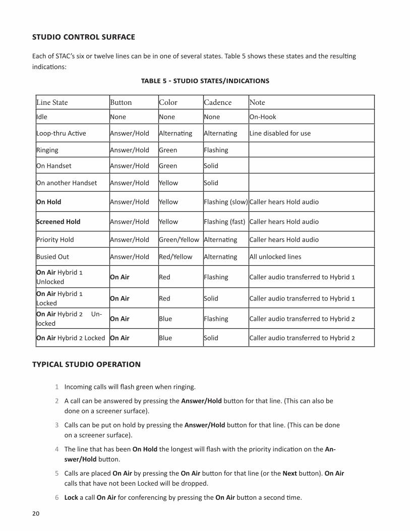
Each of STAC’s six or twelve lines can be in one of several states. Table 5 shows these states and the resulting indications:
TAbLe 5 - STUdio STATeS/iNdiCATioNS
Line State Button Color Cadence Note
Idle None None None On-Hook
Loop-thru Active Answer/Hold Alternating Alternating Line disabled for use
Ringing Answer/Hold Green Flashing
On Handset Answer/Hold Green Solid
On another Handset Answer/Hold Yellow Solid
On Hold Answer/Hold Yellow Flashing (slow) Caller hears Hold audio
Screened Hold Answer/Hold Yellow Flashing (fast) Caller hears Hold audio
Priority Hold Answer/Hold Green/Yellow Alternating Caller hears Hold audio
Busied Out Answer/Hold Red/Yellow Alternating All unlocked lines
On Air Hybrid 1 Unlocked
On Air Red Flashing Caller audio transferred to Hybrid 1
On Air Hybrid 1 Locked
On Air Red Solid Caller audio transferred to Hybrid 1
On Air Hybrid 2 Un-locked
On Air Blue Flashing Caller audio transferred to Hybrid 2
On Air Hybrid 2 Locked On Air Blue Solid Caller audio transferred to Hybrid 2
TypiCAL STUdio operATioN
1 Incoming calls will flash green when ringing.
2 A call can be answered by pressing the Answer/Hold button for that line. (This can also be done on a screener surface).
3 Calls can be put on hold by pressing the Answer/Hold button for that line. (This can be done on a screener surface).
4 The line that has been On Hold the longest will flash with the priority indication on the An-swer/Hold button.
5 Calls are placed On Air by pressing the On Air button for that line (or the Next button). On Air calls that have not been Locked will be dropped.
6 Lock a call On Air for conferencing by pressing the On Air button a second time.
21
oTher CoNTroL SUrFACe iNdiCATioNS
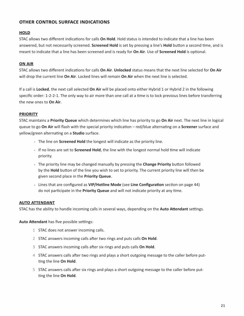
hoLdSTAC allows two different indications for calls On Hold. Hold status is intended to indicate that a line has been answered, but not necessarily screened. Screened Hold is set by pressing a line’s Hold button a second time, and is meant to indicate that a line has been screened and is ready for On Air. Use of Screened Hold is optional.
oN AirSTAC allows two different indications for calls On Air. Unlocked status means that the next line selected for On Air will drop the current line On Air. Locked lines will remain On Air when the next line is selected.
If a call is Locked, the next call selected On Air will be placed onto either Hybrid 1 or Hybrid 2 in the following specific order: 1-2-2-1. The only way to air more than one call at a time is to lock previous lines before transferring the new ones to On Air.
prioriTySTAC maintains a Priority Queue which determines which line has priority to go On Air next. The next line in logical queue to go On Air will flash with the special priority indication – red/blue alternating on a Screener surface and yellow/green alternating on a Studio surface.
• The line on Screened Hold the longest will indicate as the priority line.
• If no lines are set to Screened Hold, the line with the longest normal hold time will indicate priority.
• The priority line may be changed manually by pressing the Change Priority button followed by the Hold button of the line you wish to set to priority. The current priority line will then be given second place in the Priority Queue.
• Lines that are configured as VIP/Hotline Mode (see Line Configuration section on page 44) do not participate in the Priority Queue and will not indicate priority at any time.
AUTo ATTeNdANTSTAC has the ability to handle incoming calls in several ways, depending on the Auto Attendant settings.
Auto Attendant has five possible settings:
1 STAC does not answer incoming calls.
2 STAC answers incoming calls after two rings and puts calls On Hold.
3 STAC answers incoming calls after six rings and puts calls On Hold.
4 STAC answers calls after two rings and plays a short outgoing message to the caller before put-ting the line On Hold.
5 STAC answers calls after six rings and plays a short outgoing message to the caller before put-ting the line On Hold.
22
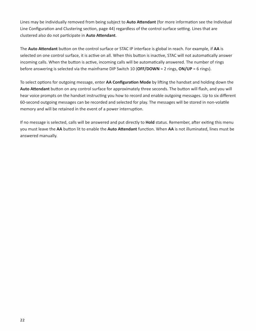
Lines may be individually removed from being subject to Auto Attendant (for more information see the Individual Line Configuration and Clustering section, page 44) regardless of the control surface setting. Lines that are clustered also do not participate in Auto Attendant.
The Auto Attendant button on the control surface or STAC IP interface is global in reach. For example, if AA is selected on one control surface, it is active on all. When this button is inactive, STAC will not automatically answer incoming calls. When the button is active, incoming calls will be automatically answered. The number of rings before answering is selected via the mainframe DIP Switch 10 (OFF/DOWN = 2 rings, ON/UP = 6 rings).
To select options for outgoing message, enter AA Configuration Mode by lifting the handset and holding down the Auto Attendant button on any control surface for approximately three seconds. The button will flash, and you will hear voice prompts on the handset instructing you how to record and enable outgoing messages. Up to six different 60-second outgoing messages can be recorded and selected for play. The messages will be stored in non-volatile memory and will be retained in the event of a power interruption.
If no message is selected, calls will be answered and put directly to Hold status. Remember, after exiting this menu you must leave the AA button lit to enable the Auto Attendant function. When AA is not illuminated, lines must be answered manually.
23
V. STAC ipAboUT STAC ip
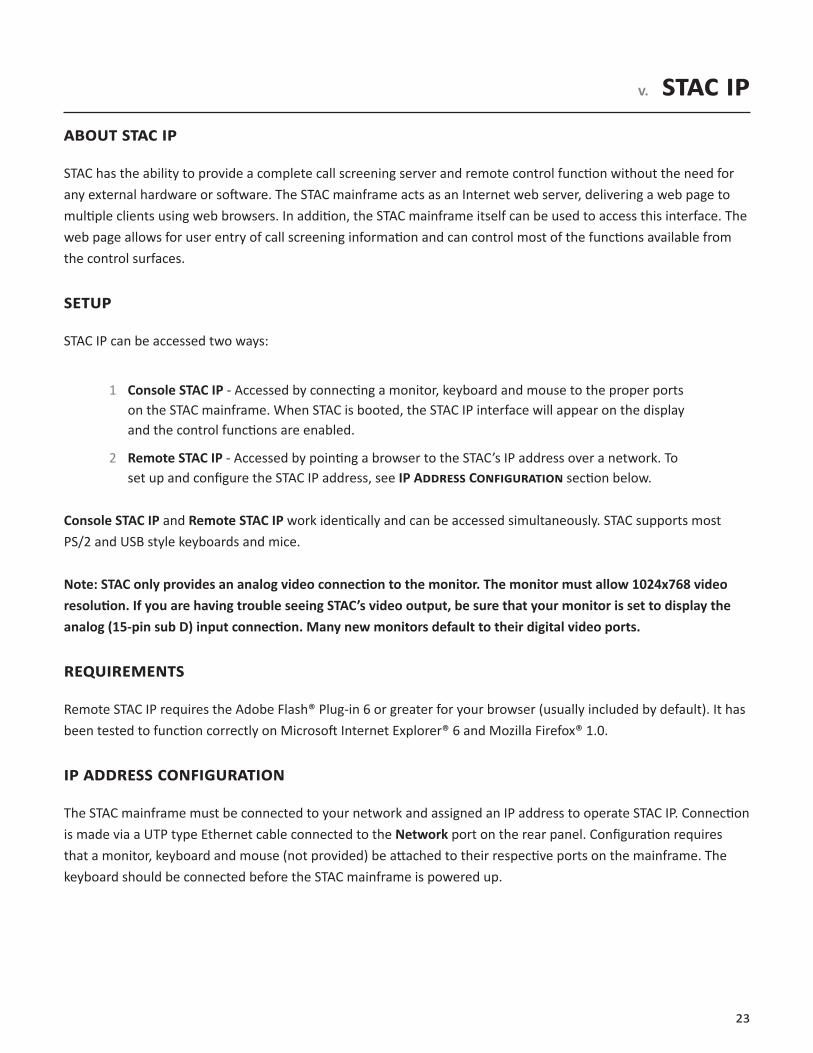
STAC has the ability to provide a complete call screening server and remote control function without the need for any external hardware or software. The STAC mainframe acts as an Internet web server, delivering a web page to multiple clients using web browsers. In addition, the STAC mainframe itself can be used to access this interface. The web page allows for user entry of call screening information and can control most of the functions available from the control surfaces.
SeTUp
STAC IP can be accessed two ways:
1 Console STAC IP - Accessed by connecting a monitor, keyboard and mouse to the proper ports on the STAC mainframe. When STAC is booted, the STAC IP interface will appear on the display and the control functions are enabled.
2 Remote STAC IP - Accessed by pointing a browser to the STAC’s IP address over a network. To set up and configure the STAC IP address, see IP AddreSS CoNFigUrATioN section below.
Console STAC IP and Remote STAC IP work identically and can be accessed simultaneously. STAC supports most PS/2 and USB style keyboards and mice.
Note: STAC only provides an analog video connection to the monitor. The monitor must allow 1024x768 video resolution. If you are having trouble seeing STAC’s video output, be sure that your monitor is set to display the analog (15-pin sub D) input connection. Many new monitors default to their digital video ports.
reqUireMeNTS
Remote STAC IP requires the Adobe Flash® Plug-in 6 or greater for your browser (usually included by default). It has been tested to function correctly on Microsoft Internet Explorer® 6 and Mozilla Firefox® 1.0.
ip AddreSS CoNFigUrATioN
The STAC mainframe must be connected to your network and assigned an IP address to operate STAC IP. Connection is made via a UTP type Ethernet cable connected to the Network port on the rear panel. Configuration requires that a monitor, keyboard and mouse (not provided) be attached to their respective ports on the mainframe. The keyboard should be connected before the STAC mainframe is powered up.
24
STATiC VS. dyNAMiC ip AddreSSiNg
STAC is able to serve web pages to clients using web browsers. In order for the browsers to find STAC on your network, STAC must be assigned an IP address. This address can be a fixed static number or can be assigned dynamically by your network, if a DHCP server is present on your network. We recommend use of STAC with a fixed IP address if possible, since DHCP addresses can change over time.
dyNAMiC CoNFigUrATioN
STAC is factory-configured for dynamic IP assignment and no configuration should be necessary. The IP address assigned to STAC by the network will appear on the Console STAC IP interface. Simply connect a monitor to the video port on the STAC mainframe to retrieve this information.
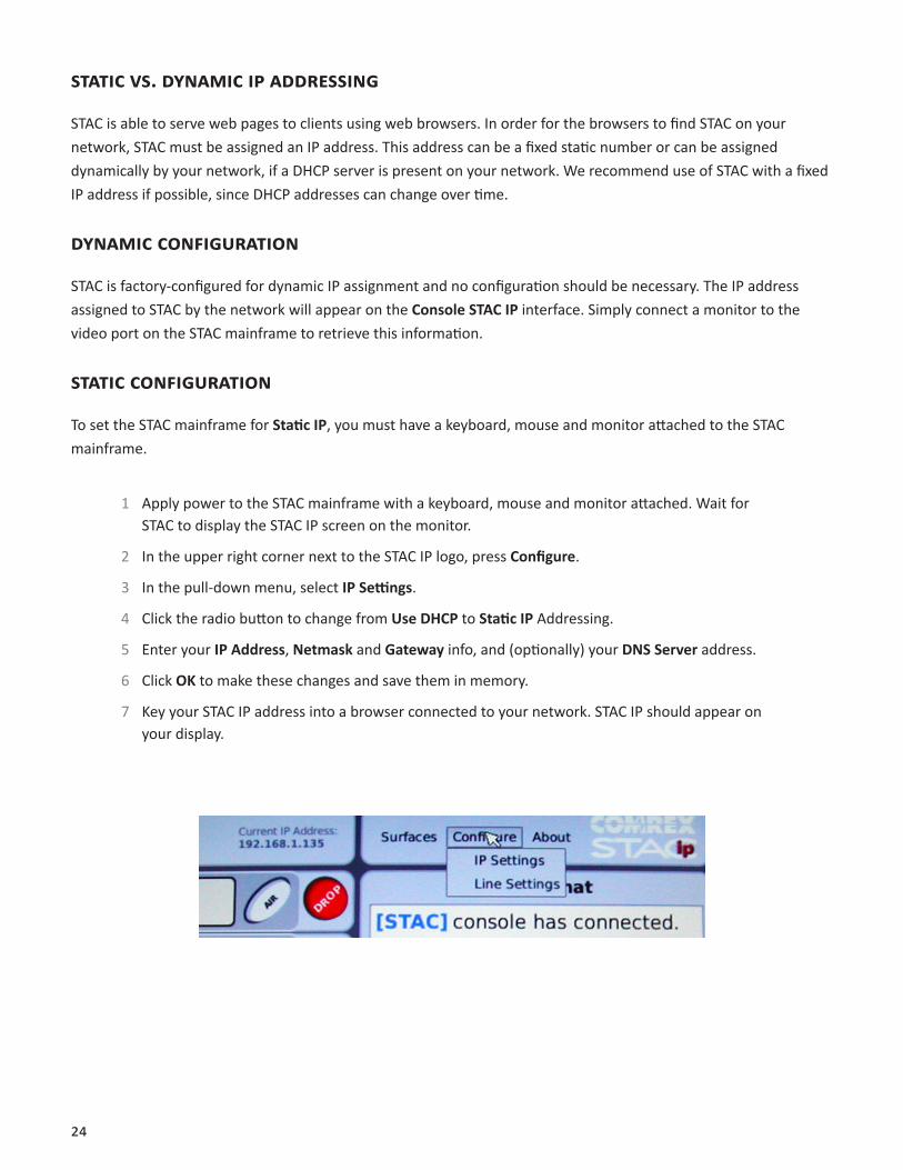
STATiC CoNFigUrATioN
To set the STAC mainframe for Static IP, you must have a keyboard, mouse and monitor attached to the STAC mainframe.
1 Apply power to the STAC mainframe with a keyboard, mouse and monitor attached. Wait for STAC to display the STAC IP screen on the monitor.
2 In the upper right corner next to the STAC IP logo, press Configure.
3 In the pull-down menu, select IP Settings.
4 Click the radio button to change from Use DHCP to Static IP Addressing.
5 Enter your IP Address, Netmask and Gateway info, and (optionally) your DNS Server address.
6 Click OK to make these changes and save them in memory.
7 Key your STAC IP address into a browser connected to your network. STAC IP should appear on your display.

25
STATiC ip NeTWorK CoNFigUrATioN SCreeN
gAiNiNg ACCeSS
When Remote STAC IP is accessed, a password screen is presented. The user may enter any user name, but the case-sensitive password must be the same as that programed into the STAC mainframe. (See page 30 for password programming information.) The default system password is comrex (lower case). The STAC IP chat window will notify all users of anyone logging in or out (by referencing their user name) and all “Studio Chat” text messages will be identified by the same name.
The Remote STAC IP screen is designed to expand automatically to your monitor’s resolution. We recommend a resolution of at least 1024x768 to view Remote STAC IP. Also, the web page is best viewed in full screen mode to make the information easiest to read. F11 toggles full screen mode on/off on most browsers.
STAC ip iNTerFACe
The STAC IP interface is designed to provide almost all the functionality of a control surface with the following exceptions:
1 In order to screen calls using STAC IP, you will need to have a control surface attached to the system. Although you can answer calls using the STAC IP interface, calls will be routed to the handset of the control surface you designate. (See Associating STAC IP With a Control Surface on page 30.)
2 STAC IP cannot dial outgoing calls, either in Answer mode or On Air. You must use a control surface keypad to dial outgoing calls.
The STAC IP screen is shown on page page 26. Note: The figure shown is for a STAC12 system. If you have STAC6, only six line fields will be shown.
26
STAC ip SCreeN
5
41 32
6 87
9
10
11
MAjor STAC ip FUNCTioNS
Here is a description of the major STAC IP functions:
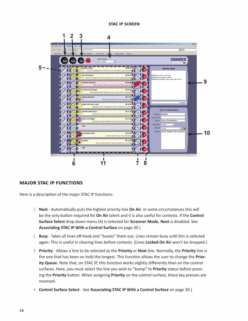
1 Next - Automatically puts the highest priority line On Air. In some circumstances this will be the only button required for On Air talent and it is also useful for contests. If the Control Surface Select drop down menu (4) is selected for Screener Mode, Next is disabled. See Associating STAC IP With a Control Surface on page 30.)
2 Busy - Takes all lines off-hook and “busies” them out. Lines remain busy until this is selected again. This is useful in clearing lines before contests. (Lines Locked On Air won’t be dropped.)
3 Priority - Allows a line to be selected as the Priority or Next line. Normally, the Priority line is the one that has been on hold the longest. This function allows the user to change the Prior-ity Queue. Note that, on STAC IP, this function works slightly differently than on the control surfaces. Here, you must select the line you wish to “bump” to Priority status before press-ing the Priority button. When assigning Priority on the control surface, these key presses are reversed.
4 Control Surface Select - See Associating STAC IP With a Control Surface on page 30.)
27
5 Answer - Functional only after control surface association. Routes a call to the selected con-trol surface handset.
6 Hold - Allows a call to be put in On Hold status. Pressing this button on a line that is already On Hold will change the line to Screened Hold status.
7 On Air - Places a call on one of the internal hybrids so it can be sent to air. Pressing this but-ton after a call is On Air will lock the call onto the hybrid and allow conferencing. Calls will be placed onto the internal hybrids in the following order:
First call: Hybrid 1
Second call: Hybrid 2
Third call: Hybrid 2
Fourth call: Hybrid 1
Up to two calls can be assigned to each of the internal hybrids. Note that if lines are not Locked, previous On Air lines are disconnected when a new one is chosen. If no lines are locked, all calls are routed to Hybrid 1.
Note: The On Air buttons are visible, but disabled, if the STAC IP session is set for Screener or associated with a screener control surface.
8 Drop - Disconnects selected line from the system.
9 Studio Chat Window - Allows text “chat” between all users of the system. Text entered into the entry field will be sent to all users when the Send button is pressed (or when the Enter key on the keyboard is pressed).
10 Line Status Entry Field - When a line is selected in any way (Answered, On Hold, or On Air), the data entry field for that line is activated, and the user is prompted to fill in the relevant information for the caller. Data appears in real time to all those viewing the STAC IP. Pull-down menus are available to select the gender of a caller and to associate the caller with a mood via the available “emotions”. The data entry field for a particular line may also be selected by clicking on the text display for that line or by using the keyboard up arrow () or down arrow () to select a line.
When entering screening text information, note that there are several reserved keys which should not be used. The Adobe Flash interface reserves Function keys (e.g. F1, F2, etc.) at the top of the keyboard for its own uses. Also, the “backtick” (the ` symbol, shared with the tilde ~, and usually just below Esc) is reserved for Command Mode (see page 29).
11 Line Status Fields - Display line status or screening information associated with a particular line.
28
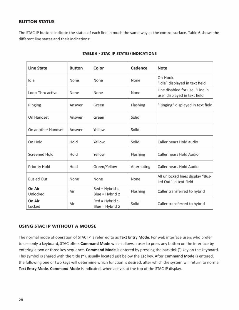
bUTToN STATUS
The STAC IP buttons indicate the status of each line in much the same way as the control surface. Table 6 shows the different line states and their indications:
TAbLe 6 - STAC ip STATeS/iNdiCATioNS
Line State Button Color Cadence Note
Idle None None NoneOn-Hook.“idle” displayed in text field
Loop-Thru active None None NoneLine disabled for use. “Line in use” displayed in text field
Ringing Answer Green Flashing “Ringing” displayed in text field
On Handset Answer Green Solid
On another Handset Answer Yellow Solid
On Hold Hold Yellow Solid Caller hears Hold audio
Screened Hold Hold Yellow Flashing Caller hears Hold Audio
Priority Hold Hold Green/Yellow Alternating Caller hears Hold Audio
Busied Out None None NoneAll unlocked lines display “Bus-ied Out” in text field
On AirUnlocked
AirRed = Hybrid 1Blue = Hybrid 2
Flashing Caller transferred to hybrid
On Air Locked
AirRed = Hybrid 1Blue = Hybrid 2
Solid Caller transferred to hybrid
USiNg STAC ip WiThoUT A MoUSe
The normal mode of operation of STAC IP is referred to as Text Entry Mode. For web interface users who prefer to use only a keyboard, STAC offers Command Mode which allows a user to press any button on the interface by entering a two or three key sequence. Command Mode is entered by pressing the backtick (`) key on the keyboard. This symbol is shared with the tilde (~), usually located just below the Esc key. After Command Mode is entered, the following one or two keys will determine which function is desired, after which the system will return to normal Text Entry Mode. Command Mode is indicated, when active, at the top of the STAC IP display.
29
iNdiVidUAL LiNe CoMMANdS
Functions performed on a particular line require three key presses, including the Command Mode key.
Once Command Mode is entered, press the key for the line of your choice. Lines 1-9 are accessed by pressing their corresponding numerical keys. For example, line 1 is accessed by pressing the one (1) key. Line 10 is selected with the zero (0) key, line 11 is selected with the dash (–) key, and line 12 by the equal (=) key. This is followed by a key to determine which function is to be performed. These are the function keys:
a - Answer call h - Place call On Hold/Screened Hold d - Drop call o - Put call On Air/lock call On Air p - Change Priority of current line
For example, to put line 9 on Hold, you would type `9h and to Drop line 12, you would type `=d
Note that the Answer (a) and On Air (o) commands are sometimes disabled, based on whether you are working as a Screener or Studio surface. (See page 19.)
gLobAL CoMMANdS
Functions that do not specify a particular line require only two key presses, including the Command Mode key.
These are the global commands: n - Put Next Priority line to air (Only if STAC IP is configured for Studio)
t - Toggle Auto Attendant on/off b - Toggle Busy Out
For example, to Busy Out all lines, type `b
eSCApiNg CoMMANd Mode preMATUreLy
Pressing the Tab key anytime from Command Mode will abort this mode and return to Text Entry Mode. The cursor will be placed in the chat window.
oTher FUNCTioNS
While in Text Entry Mode in STAC IP, pressing the Tab key will scroll through the various text boxes.
The up arrow () and down arrow () keys select lines for text entry.
The Control key will move the cursor to the chat field at any time.

30
ASSoCiATiNg STAC ip WiTh A CoNTroL SUrFACe
It is possible to “assign” a STAC IP session, either console or remote, to a control surface port. This allows for screening of calls completely via the STAC IP system. In essence, along with all its usual functions, the STAC IP program will determine which lines get routed to the handset of a control surface.
Control surface assignment is done via the Surfaces menu at the top of the STAC IP screen. This menu has the following options:
TAbLe 7 - CoNTroL SUrFACe ASSigNMeNT MeNU
Option Meaning
NONE:Studio (default)
No control surface association, Answer Buttons non-functional, On Air Buttons functional
NONE:Screener No control surface association, Answer Buttons non-functional, On Air Buttons non-functional
1:Studio1:Screener2:Studio2:Screener3:Studio3:Screener4:Studio4:Screener
Based on number of control surfaces attached (and Studio/Screener settings of each) these options will appear. Selec-tion of one of these options will enable the Answer buttons. Answered calls will be routed to the selected control surface handset. On Air buttons are enabled only if the associated control surface is set for Studio mode.
ChANgiNg The STAC ip pASSWord
To change the STAC IP password, you must have a keyboard, mouse and monitor attached to the STAC mainframe.
1 Apply power to the STAC mainframe with a keyboard, mouse and monitor attached. Wait for STAC to display the STAC IP screen on the monitor.
2 In the upper right corner next to the STAC IP logo, press Configure.
3 In the pull-down menu, select IP Settings.
4 Change the STAC IP password in the field labeled GUI Password.
5 Click OK to make these changes and save them in memory.
31
STAC ip gUi pASSWord CoNFigUrATioN SCreeN
TroUbLeShooTiNg reMoTe STAC ip
If you are unable to access STAC IP from a remote computer after verifying all STAC IP configuration settings, you may have a firewall issue blocking access. STAC IP requires that TCP port 8080 be open on your system to operate correctly. You may need to configure your firewall or router to enable this port.
It’s fairly straightforward to serve STAC IP information around a LAN, but things become more complex when STAC IP needs to be delivered over the public Internet. In essence, STAC can be treated like any other Internet server in that it requires a known, public IP address to be accessed. If your network infrastructure has a firewall that prevents unsolicited traffic from entering or blocks off all ports other than those that are “well-known” or uses Network Address Translation (NAT), you will need to modify your network to allow STAC to deliver STAC IP to the outside world.
32
deLiVeriNg STAC ip oUTSide The LAN eNViroNMeNT
It’s not possible to make specific recommendations on how to alter anyone’s network to allow this. We recommend consultation by an IT professional to set up or make changes to your network. We can, however, make the following general suggestions:
1 If you cannot remotely access STAC IP, don’t assume that it’s always the fault of the network on the STAC side. Double check the STAC IP settings (especially the netmask and gateway settings). Try a different computer. Be sure you have Adobe Flash 6 or higher installed. Try another browser if possible.
2 By definition, Network Address Translation (NAT) and Internet servers are not compatible. If your network uses NAT, you will need to locate STAC in front of the NAT. To obtain a publicly accessible IP, create a DMZ in your router to allow public access to the STAC. STAC uses TCP ports 80 and 8080.
3 If you do suspect firewall issues, try opening port 8080 to TCP traffic on your firewall. You’ll need this port to be open on your client’s firewall as well.
4 If you do find that your network won’t allow a server, investigate a Virtual Private Network (VPN). This will allow you to keep your firewall security settings for the general network, but looser settings for STAC, with the VPN providing its own security.
5 A VPN is a good idea even for those without network access issues. STAC only provides a sim-ple password protection and allowing external access only via VPN increases security dramati-cally.
6 Check the Comrex support page at www.comrex.com/support for updates. We will post any info we get on network compatibility.
33
Vi. STAC hybrid SeTUp ANd operATioNSTAC bLoCK diAgrAM
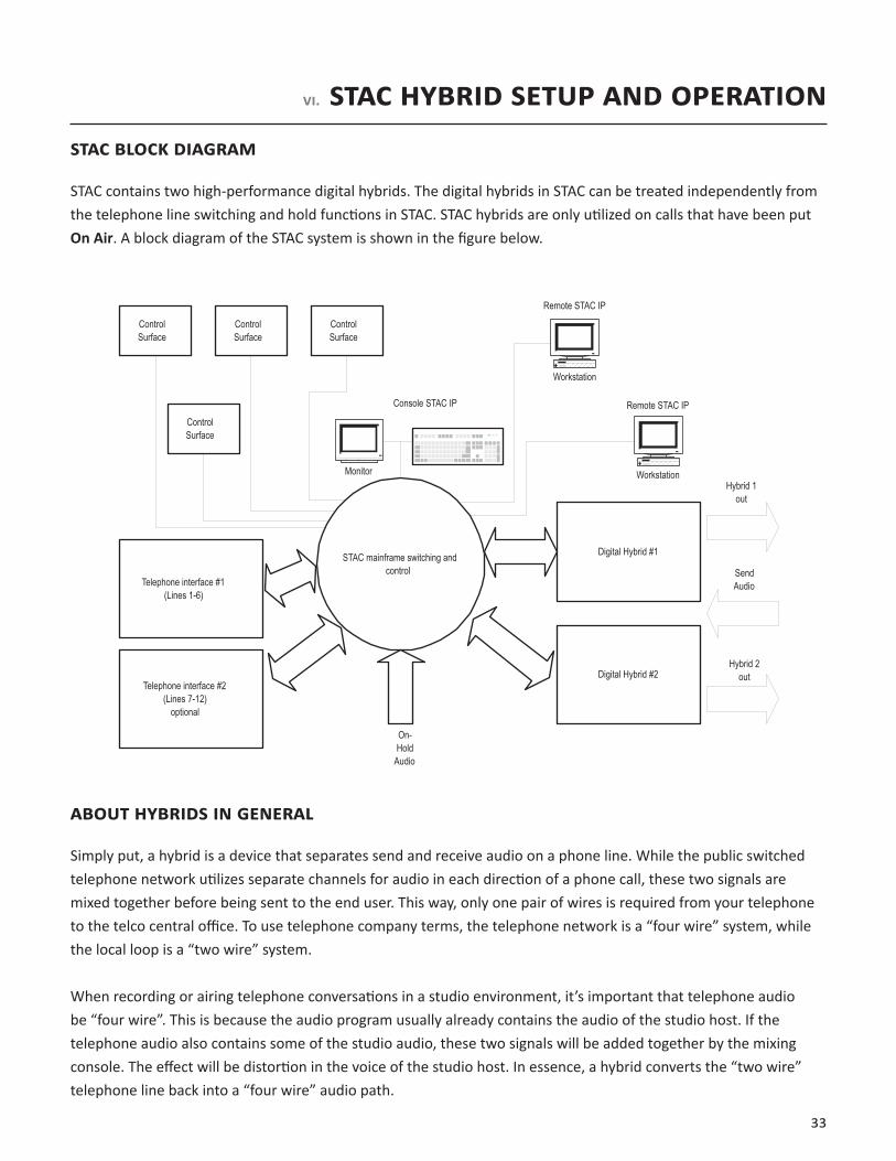
STAC contains two high-performance digital hybrids. The digital hybrids in STAC can be treated independently from the telephone line switching and hold functions in STAC. STAC hybrids are only utilized on calls that have been put On Air. A block diagram of the STAC system is shown in the figure below.
Digital Hybrid #1
Digital Hybrid #2
Telephone interface #1(Lines 1-6)
Telephone interface #2(Lines 7-12)
optional
STAC mainframe switching andcontrol
On-Hold
Audio
ControlSurface
ControlSurface
ControlSurface
ControlSurface
Monitor
Console STAC IP
Workstation
Workstation
Remote STAC IP
Remote STAC IP
SendAudio
Hybrid 1out
Hybrid 2out
AboUT hybridS iN geNerAL
Simply put, a hybrid is a device that separates send and receive audio on a phone line. While the public switched telephone network utilizes separate channels for audio in each direction of a phone call, these two signals are mixed together before being sent to the end user. This way, only one pair of wires is required from your telephone to the telco central office. To use telephone company terms, the telephone network is a “four wire” system, while the local loop is a “two wire” system.
When recording or airing telephone conversations in a studio environment, it’s important that telephone audio be “four wire”. This is because the audio program usually already contains the audio of the studio host. If the telephone audio also contains some of the studio audio, these two signals will be added together by the mixing console. The effect will be distortion in the voice of the studio host. In essence, a hybrid converts the “two wire” telephone line back into a “four wire” audio path.

34
It seems counter intuitive, but the main goal of a studio hybrid is to improve the sound of the people in the studio, not the callers. If the hybrid isn’t working well, people speaking from the studio will sound “hollow” or like they’re “talking into a barrel”. This is due to the strange effect of mixing microphone audio with telephone “bleed-through”. Of course, our hybrids also improve the audio of callers, filtering out hum and noise as well as adjusting levels between loud and soft speakers.
It is our opinion that with the advent of cheap telephones, cordless phones and cellphones, telephone audio has gotten decidedly worse in recent years. While a hybrid can clean up noise to some extent, it cannot remove distortion caused by the far end telephone. If you find some calls sound good on the air and some don’t, it’s probably due to the large disparity in audio quality of today’s telephone sets.
AboUT The STAC hybridS
STAC uses digital signal processing (DSP) technology to continually adapt to telephone-line conditions – providing consistent, high-quality sound and send-to-caller separation. The hybrids help bring uniformity and high quality sound to a broadcast talk show environment.
STAC contains two digital hybrids. Only one STAC hybrid is used in normal use (e.g. contests, requests, interviews). Both hybrids are utilized only when more than one call is on the air at the same time. This is done by Locking one call on the control surface (or STAC IP) and putting another call on the air.
Callers on both hybrids will hear audio applied to the Send Input on the STAC mainframe. Audio from the caller(s) on Hybrid 1 is available on the Hybrid 1 Output port. Audio from the caller(s) on Hybrid 2 is available on the Hybrid 2 Output port. Audio from callers on both hybrids is available on the Aux Output port. Hybrid 1 caller audio is also routed to Hybrid 2 and Hybrid 2 caller audio is routed to Hybrid 1. This allows callers to hear each other as well as the studio-generated audio. This also allows a single “mix-minus” (audio without any callers) to be applied to the Send Input. This function cannot be defeated – i.e. callers always hear the audio from the other hybrid, and two separate “mix-minuses” are not supported. If this function is essential, see Connection of an External Hybrid on page 40 and Appendix B on page 52.
Each hybrid is technically capable of supporting two calls simultaneously. This is done by simply summing the lines together in a “button mashing” fashion. If there are differences in level between these lines, this scenario may not perform very well. For optimal hybrid performance, we recommend one call per hybrid.
TeLephoNe SepArATioN/NULL
Using Digital Signal Processing (DSP) technology and firmware, the interface between a standard analog POTS line and your audio equipment will result in superior quality audio. The primary function of STAC hybrids is to maximize the null by maximizing the separation of send and caller audio. Both hybrids provide >55 dB null between 250 Hz to 3.5 kHz.
35
AUToMATiC gAiN CoNTroL
AGC normalizes the gain of caller audio, augmenting the level of soft callers, and attenuating the level of loud callers. This helps provide more uniform caller audio levels at the caller output of the hybrid. The AGC threshold is -50 dBm. The AGC works to achieve an average caller level of -30 dBm from the telephone circuit.
AUToMATiC Mix-MiNUS
STAC’s Auto Mix-Minus creates a mix-minus for the hybrids when one is not available from the audio console. See the About Mix-Minus section on page 35 for further information.
CALLer CoNTroL
Caller control, also known as ducking, attenuates the caller input audio when send audio is present. The purpose of this attenuation is to allow the talent to dominate their conversation with the callers. The amount of caller control (attenuation) applied to the caller audio is selectable from 0 to 18 dB, in 6 dB increments. For details, see DIP Switches on page 17.
AboUT Mix-MiNUS
Mix-minus refers to the generation of a special audio signal to be fed to callers on the STAC. Essentially, it is a mix of all audio being sent over the air MINUS the callers themselves. This feed is only applied to the Main Send Input on the STAC. The On Hold audio typically contains the entire program feed, including callers.
36
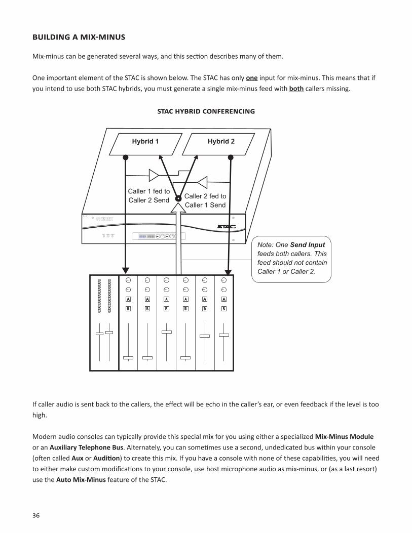
bUiLdiNg A Mix-MiNUS
Mix-minus can be generated several ways, and this section describes many of them.
One important element of the STAC is shown below. The STAC has only one input for mix-minus. This means that if you intend to use both STAC hybrids, you must generate a single mix-minus feed with both callers missing.
STAC hybrid CoNFereNCiNg
INPUT HYBRID 1 HYBRID 2
Hybrid 1 Hybrid 2
Caller 1 fed to Caller 2 Send Caller 2 fed to
Caller 1 Send
Note: One Send Input feeds both callers. This feed should not contain Caller 1 or Caller 2.
If caller audio is sent back to the callers, the effect will be echo in the caller’s ear, or even feedback if the level is too high.
Modern audio consoles can typically provide this special mix for you using either a specialized Mix-Minus Module or an Auxiliary Telephone Bus. Alternately, you can sometimes use a second, undedicated bus within your console (often called Aux or Audition) to create this mix. If you have a console with none of these capabilities, you will need to either make custom modifications to your console, use host microphone audio as mix-minus, or (as a last resort) use the Auto Mix-Minus feature of the STAC.
37
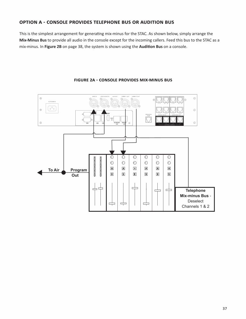
opTioN A - CoNSoLe proVideS TeLephoNe bUS or AUdiTioN bUS
This is the simplest arrangement for generating mix-minus for the STAC. As shown below, simply arrange the Mix-Minus Bus to provide all audio in the console except for the incoming callers. Feed this bus to the STAC as a mix-minus. In Figure 2B on page 38, the system is shown using the Audition Bus on a console.
FigUre 2A - CoNSoLe proVideS Mix-MiNUS bUS
AC POWER IN
SEND IN HOLD AUDIO IN AUX OUT HYBRID 1 OUT HYBRID 2 OUT
EXPANSIONPORT
7 - 9 10 - 12 7 - 9 10 - 12
1 - 3 1 - 34 - 6 4 - 6PHONE LINE IN LOOP-THRU OUT
CONTROL SURFACE1 2 3 4
SERIAL
VGA USB USB
HDMI
RESET
PRIMARYLAN
SECONDARYLAN
Telephone Mix-minus Bus -
Deselect Channels 1 & 2
To Air Program Out
38
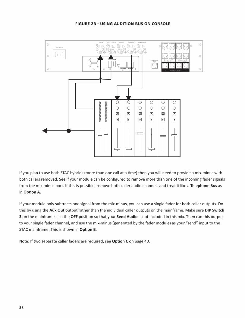
FigUre 2b - USiNg AUdiTioN bUS oN CoNSoLe
AC POWER IN
SEND IN HOLD AUDIO IN AUX OUT HYBRID 1 OUT HYBRID 2 OUT
EXPANSIONPORT
7 - 9 10 - 12 7 - 9 10 - 12
1 - 3 1 - 34 - 6 4 - 6PHONE LINE IN LOOP-THRU OUT
CONTROL SURFACE1 2 3 4
SERIAL
VGA USB USB
HDMI
RESET
PRIMARYLAN
SECONDARYLAN
If you plan to use both STAC hybrids (more than one call at a time) then you will need to provide a mix-minus with both callers removed. See if your module can be configured to remove more than one of the incoming fader signals from the mix-minus port. If this is possible, remove both caller audio channels and treat it like a Telephone Bus as in Option A.
If your module only subtracts one signal from the mix-minus, you can use a single fader for both caller outputs. Do this by using the Aux Out output rather than the individual caller outputs on the mainframe. Make sure DIP Switch 3 on the mainframe is in the OFF position so that your Send Audio is not included in this mix. Then run this output to your single fader channel, and use the mix-minus (generated by the fader module) as your “send” input to the STAC mainframe. This is shown in Option B.
Note: If two separate caller faders are required, see Option C on page 40.
39
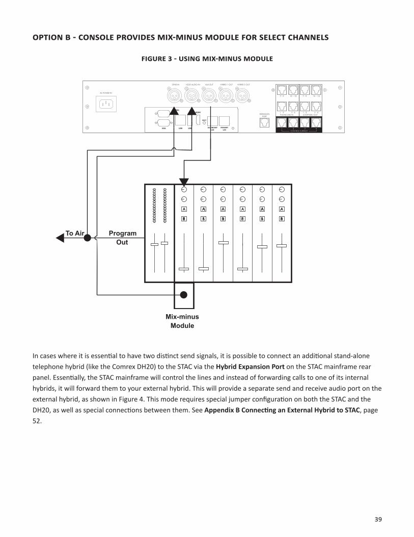
opTioN b - CoNSoLe proVideS Mix-MiNUS ModULe For SeLeCT ChANNeLS
FigUre 3 - USiNg Mix-MiNUS ModULe
AC POWER IN
SEND IN HOLD AUDIO IN AUX OUT HYBRID 1 OUT HYBRID 2 OUT
EXPANSIONPORT
7 - 9 10 - 12 7 - 9 10 - 12
1 - 3 1 - 34 - 6 4 - 6PHONE LINE IN LOOP-THRU OUT
CONTROL SURFACE1 2 3 4
SERIAL
VGA USB USB
HDMI
RESET
PRIMARYLAN
SECONDARYLAN
To Air Program Out
Mix-minus Module
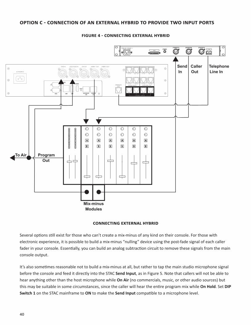
In cases where it is essential to have two distinct send signals, it is possible to connect an additional stand-alone telephone hybrid (like the Comrex DH20) to the STAC via the Hybrid Expansion Port on the STAC mainframe rear panel. Essentially, the STAC mainframe will control the lines and instead of forwarding calls to one of its internal hybrids, it will forward them to your external hybrid. This will provide a separate send and receive audio port on the external hybrid, as shown in Figure 4. This mode requires special jumper configuration on both the STAC and the DH20, as well as special connections between them. See Appendix B Connecting an External Hybrid to STAC, page 52.
40
opTioN C - CoNNeCTioN oF AN exTerNAL hybrid To proVide TWo iNpUT porTS
FigUre 4 - CoNNeCTiNg exTerNAL hybrid
SEND IN CALLER OUT AUX OUT
AC POWER IN
SEND IN HOLD AUDIO IN AUX OUT HYBRID 1 OUT HYBRID 2 OUT
EXPANSIONPORT
7 - 9 10 - 12 7 - 9 10 - 12
1 - 3 1 - 34 - 6 4 - 6PHONE LINE IN LOOP-THRU OUT
CONTROL SURFACE1 2 3 4
SERIAL
VGA USB USB
HDMI
RESET
PRIMARYLAN
SECONDARYLAN
To Air Program Out
Mix-minus Modules
Send Caller Telephone In Out Line In
CoNNeCTiNg exTerNAL hybrid
Several options still exist for those who can’t create a mix-minus of any kind on their console. For those with electronic experience, it is possible to build a mix-minus “nulling” device using the post-fade signal of each caller fader in your console. Essentially, you can build an analog subtraction circuit to remove these signals from the main console output.
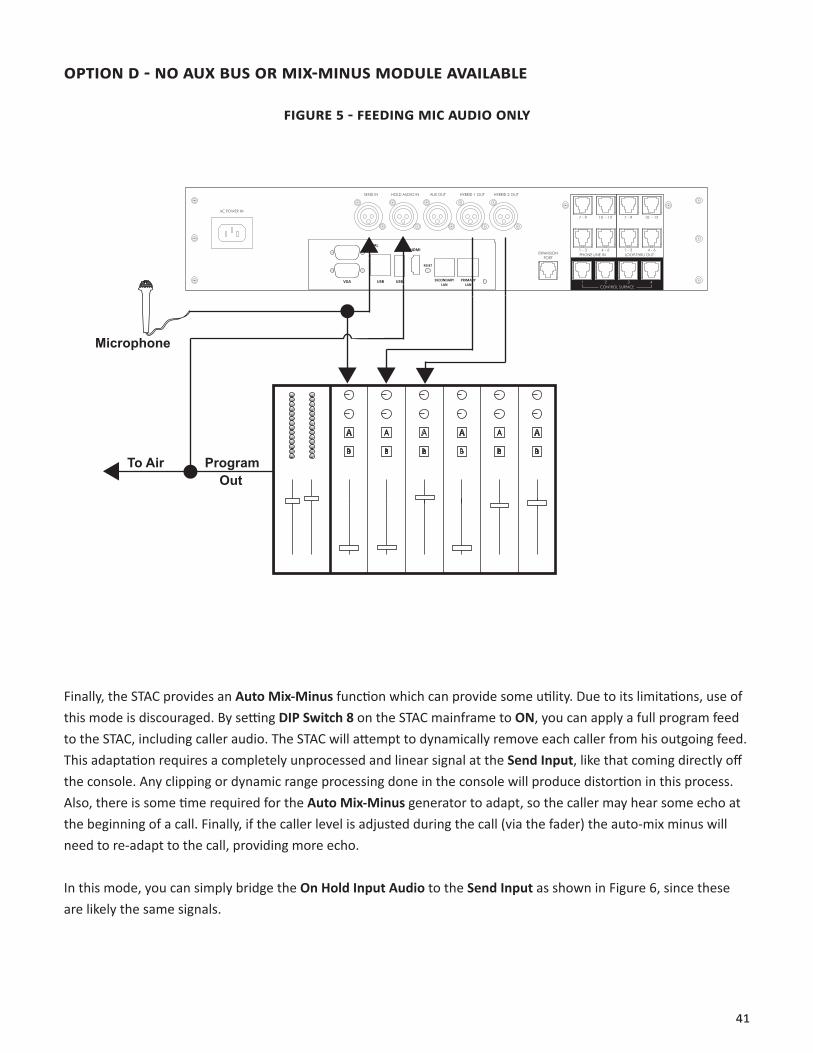
It’s also sometimes reasonable not to build a mix-minus at all, but rather to tap the main studio microphone signal before the console and feed it directly into the STAC Send Input, as in Figure 5. Note that callers will not be able to hear anything other than the host microphone while On Air (no commercials, music, or other audio sources) but this may be suitable in some circumstances, since the caller will hear the entire program mix while On Hold. Set DIP Switch 1 on the STAC mainframe to ON to make the Send Input compatible to a microphone level.
41
opTioN d - No AUx bUS or Mix-MiNUS ModULe AVAiLAbLe
FigUre 5 - FeediNg MiC AUdio oNLy
AC POWER IN
SEND IN HOLD AUDIO IN AUX OUT HYBRID 1 OUT HYBRID 2 OUT
EXPANSIONPORT
7 - 9 10 - 12 7 - 9 10 - 12
1 - 3 1 - 34 - 6 4 - 6PHONE LINE IN LOOP-THRU OUT
CONTROL SURFACE1 2 3 4
SERIAL
VGA USB USB
HDMI
RESET
PRIMARYLAN
SECONDARYLAN
To Air Program Out
Microphone
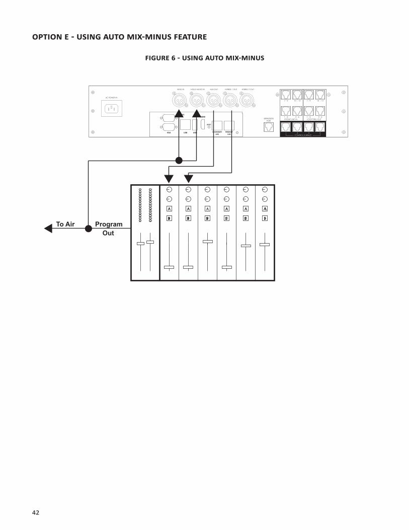
Finally, the STAC provides an Auto Mix-Minus function which can provide some utility. Due to its limitations, use of this mode is discouraged. By setting DIP Switch 8 on the STAC mainframe to ON, you can apply a full program feed to the STAC, including caller audio. The STAC will attempt to dynamically remove each caller from his outgoing feed. This adaptation requires a completely unprocessed and linear signal at the Send Input, like that coming directly off the console. Any clipping or dynamic range processing done in the console will produce distortion in this process. Also, there is some time required for the Auto Mix-Minus generator to adapt, so the caller may hear some echo at the beginning of a call. Finally, if the caller level is adjusted during the call (via the fader) the auto-mix minus will need to re-adapt to the call, providing more echo.
In this mode, you can simply bridge the On Hold Input Audio to the Send Input as shown in Figure 6, since these are likely the same signals.
42
opTioN e - USiNg AUTo Mix-MiNUS FeATUre
FigUre 6 - USiNg AUTo Mix-MiNUS
AC POWER IN
SEND IN HOLD AUDIO IN AUX OUT HYBRID 1 OUT HYBRID 2 OUT
EXPANSIONPORT
7 - 9 10 - 12 7 - 9 10 - 12
1 - 3 1 - 34 - 6 4 - 6PHONE LINE IN LOOP-THRU OUT
CONTROL SURFACE1 2 3 4
SERIAL
VGA USB USB
HDMI
RESET
PRIMARYLAN
SECONDARYLAN
To Air Program Out

43
TriM poTS
The front panel trim pots provide level adjustments of the Send, Aux Send, Aux Out and Caller Out audio connections. Separate audio level controls let you optimize the audio level(s) of STAC to match the audio levels required by the interfaced audio equipment.
In order to optimize the audio levels, have someone call the hybrid from another location. Answer the line on a control surface and make adjustments to the Send In, Hold Audio, and Caller Output controls. Be aware that some suppression and/or echo may be heard while calibrating the audio levels. Disregard this and continue until the end of the procedure. When the hybrid is properly calibrated there will be no echo or suppression.
INPUT HYBRID 1 HYBRID 2
1 2 3 4 5
1 Send Level Adjust - This pot adjusts the audio sent to callers when they are On Air. Adjust this pot along with your console audio control until callers verify that the audio level they are receiving is at a comfortable listening level. With comfortable listening levels, the Send LED should illuminate solid green with an occasional flash of amber on audio peaks. If the Send LED illuminates red, the audio levels are clipping and should be decreased via the send level adjustments.
2 On Hold Send Audio Adjust - This pot adjusts the level of the audio sent to callers when they are placed On Hold. This is usually a complete, undelayed program feed. Adjust this pot along with your console audio control until callers verify that the audio level they are receiving is at a comfortable listening level.
3 Aux Out Receive Audio Adjust - This pot adjusts the level of send and caller audio at the Aux Out connector. Adjust this pot along with your console audio control to set the proper level for your recording device or other external devices.
4 Hybrid 1 Out - This pot adjusts the Hybrid 1 Out audio. Adjust this pot along with your console audio control to set the caller’s voice/audio to a comfortable listening level.
5 Hybrid 2 Out - This pot adjusts the Hybrid 2 Out audio. Adjust this pot along with your console audio control to set the caller’s voice/audio to a comfortable listening level.
Note: The caller trim pots have no effect on the caller LEDs. The caller LEDs indicate actual level from the telephone lines only. If the caller LED flashes green only occasionally with caller audio, the level from the tele- phone line is too low and you should activate Caller Boost by setting DIP Switch 2 to ON. (See DIP Switches on page 12.)
44
Vii. iNdiVidUAL LiNe CoNFigUrATioN ANd CLUSTeriNg
iNTrodUCTioN
For users with advanced requirements, STAC has the capability of configuring lines for some features on an individual basis. It also has the ability to enable “Clustering” or sharing of individual lines between multiple STAC mainframes. Line Configuration and Clustering are both configured in the STAC IP Line Settings menu.
ACCeSSiNg LiNe SeTTiNgS
To configure the STAC Line Settings, you must have a keyboard, mouse and monitor attached to the STAC mainframe.
1 Apply power to the STAC mainframe with a keyboard, mouse and monitor attached. Wait for STAC to display the STAC IP screen on the monitor.
2 In the upper right corner next to the STAC IP logo, press Configure.
3 In the pull-down menu, select Line Settings.
LiNe CoNFigUrATioN
Set the Line Configuration as desired. Note:12 lines are always shown, regardless of whether you have a STAC6 or STAC12. STAC6 users may ignore the lines 7-12 settings. The choices for each line are:
1 Normal/AA Enabled (default setting) – This line will participate in Auto Attendant (if enabled) and will participate in the Priority Queue. It will provide the priority indication and be sent to On Air state with the Next Button.
2 Normal/No AA - This line will not participate in the Auto Attendant function (it will never auto-answer) but will participate in the Priority Queue.
3 VIP/Hotline - This line will not participate in the Auto Attendant or the Priority Queue. This mode is useful in dedicating a line for studio “Hotline” use, or to provide a special phone number for guests to call in to be put On Air. In order for this feature to be fully enabled DIP Switch 9 must be in the UP/ON position.
If you never intend to utilize the Auto Attendant function, we recommend configuring all lines to Normal/No AA mode to globally disable AA, regardless of the control surface setting.
When you have finished the Line Configuration, press OK to save the changes to memory.

45
STAC LiNe CoNFigUrATioN SCreeN
46
LiNe CLUSTeriNg
If you own multiple STACs, you can share lines and transfer calls between them using Clustering Mode. This is done by routing the phone line(s) of interest to both STAC mainframes, and configuring STACs to share status information about these lines across the IP network. In this mode, STACs act very much like legacy key telephone systems, allowing calls to be put On Hold on one STAC, and then picked up by another STAC. The main features of STAC Clustering Mode are:
• Shared lines are indicated as In Use (on Handset or On Air), Ringing or Available on all STACs.
• Lines that are In Use on one STAC are locked out of all other clustered STACs.
• Lines that are put On Hold on one STAC are indicated as On Hold on all clustered STACs.
• Lines indicated as On Hold may be utilized by any clustered STAC.
• Up to 12 STACs can be configured to the clustered lines across a network.
The limitations of STAC Clustering Mode are:
• Clustered lines must be assigned to the same line number in all STACs. For example, line 3 on STAC A must be applied to line 3 on STAC B.
• All STACs must be visible to each other across the LAN, and must have IP addresses within the subnet mask set on each device (I.e., they must be on the same LAN).
• Up to 256 different STAC clusters may exist on a single LAN.
• Clustered lines are automatically removed from Auto Attendant.
• It is not necessary to know the IP address of other STACs in a cluster; STACs programmed for the same cluster will find each other over the network and share information automatically.
CoNFigUriNg LiNe CLUSTeriNg
Line Clustering is enabled in the STAC IP Line Settings Menu. Enter the Line Settings menu as detailed in the Accessing Line Settings section on page 44.
Select Clustering Enabled in this menu. You will need to designate a cluster ID (if you intend to have only one cluster on your network, leave the default value of 100). This is to allow multiple clusters to exist on the same network. Allowable values are 0-255. Note: All STACs clustered together must have the same cluster number applied. Lines can not be shared across cluster numbers.
Next, use the Line pull-down menus to individually enable Clustering. Choose which lines are to be clustered and select Cluster from the pull-down menu.
When you have completed configuring Clustering Mode, click OK to save the changes to memory.

47
CLUSTeriNg operATioN
Operating a control surface or STAC IP on clustered lines is very similar to normal operation. If a line is In Use (either On Handset or On Air) on another clustered STAC, it will indicate as solid yellow (remote handset) and no control is possible. If a line is put On Hold on any STAC in the cluster, it will be indicated as On Hold on all control surfaces and STAC IP screens. The line status field of STAC IP also notes that the line has been put On Hold remotely if it was not done locally.

48
Viii. AppeNdix A - CoNForMiTy ANd regULATory iNForMATioN
SUppLier’S deCLArATioN oF CoNForMiTy
Place of Issue: Devens, Massachusetts
Date of Issue: October 31, 2011
Comrex Corporation, located at 19 Pine Road, Devens, MA in the United States of America hereby certifies that the Comrex STAC Classic System bearing identification number US:DXDKF08BSTAC complies with the Federal Communications Commission’s (“FCC”) Rules and Regulations 47 CFR Part 68, and the Administrative Council on Terminal Attachments (“ACTA”)-adopted technical criteria TIA/EIA/IS-968, Telecommunications – Telephone Terminal Equipment – Technical Requirements for Connection of Terminal Equipment To the Telephone Network, July 2001.
Comrex Corporation hereby asserts that the Comrex STAC System complies with §68.316 of the FCC Rules and Regulations defining Hearing Aid Compatible (“HAC”) and, as such, is deemed compatible with hearing aids.
___________________________________Thomas O. Hartnett, Vice President, Comrex Corporation
Note: This equipment has been tested and found to comply with the limits for a Class A digital device, pursuant to part 15 of the FCC Rules. These limits are designed to provide reasonable protection against harmful interference when the equipment is operated in a commercial environment. This equipment generates, uses, and can radiate radio frequency energy and, if not installed and used in accordance with the instruction manual, may cause harmful interference to radio communications. Operation of this equipment in a residential area is likely to cause harmful interference in which case the user will be required to correct the interference at his own expense.
49
deCLArATioN oF CoNForMiTy For TerMiNAL eqUipMeNT - iN ACCordANCe WiTh iSo/ieC gUide 22
No. 62-4323
Declaring Party: Comrex CorporationAddress: 19 Pine Road Devens, MA 01434
Terminal Equipment: Comrex STAC Classic System
The product described above is in conformity with: Document No.: ICES-03, Part I Title: Harmonized Requirements for Terminal Equipment, Terminal Systems, and Certified Protection Circuitry Edition/Date of Issue: Issue 8, March 5, 2001
Additional Information: Telephone talk show system designed for use in radio/TV stations or audio production facilities.
Place of Issue: 19 Pine Road, Devens, MA 01434 Date of Issue: October 31, 2011
Thomas O. Hartnett, Vice President
(Name & Function) (Signature)
50
eC deCLArATioN oF CoNForMiTy For r&TTe direCTiVe
We:
Manufacturer’s Name: Comrex Corporation
Manufacturer’s Address: 19 Pine Road Devens, MA 01434
hereby declare on our sole responsibility that the product:
Comrex STAC Classic SystemTelephone Talk Show System
to which this declaration relates is in conformity with the essential requirements and other relevant requirements of the R&TTE Directive (1999/5/EC). This product is compliant with the following standards and other normative documents:
European EMC Directive (89/336/EEC) EN 55103-1; 2009 (Emissions) EN 55103-2; 2009 (Immunity)Low Voltage Directive (2006/95/EG) EN 60950
Information regarding configuration of this equipment for operation on the telephone networks of the EC countries may be found in the STAC System product manual.
Contact person: Thomas O. Hartnett, V.P., Engineering
Signed:____________________________________________________
Date: October 31, 2011
51
regULATory iNForMATioN
This equipment complies with Part 68 of the FCC rules and the requirements adopted by the ACTA, as well as the applicable Industry Canada technical specifications. On the bottom of this equipment is a label that contains, among other information, a product identifier in the format US:DXDKF08BSTAC. If requested, this number must be provided to a U.S. telephone company.
Telephone line connections to the Comrex STAC are made via 8-pin modular connectors wired as described in this manual. Customers needing RJ-11C terminations should contact Comrex Corporation or one of its dealers to order STAC “break-out” adapters.
The REN is used to determine the number of devices that may be connected to a telephone line. Excessive RENs on a telephone line may result in the devices not ringing in response to an incoming call. The sum of RENs should not exceed five (5.0). To be certain of the number of devices that may be connected to a line, as determined by the total RENs, contact the local telephone company. The REN for the Comrex STAC is 0.8, and is shown as the digits represented by 08 in the product identifier US:DXDKF08BSTAC.
If the Comrex STAC causes harm to the telephone network, the telephone company will notify you in advance that temporary discontinuance of service may be required. But if advance notice isn’t practical, the telephone company will notify the customer as soon as possible. Also, you will be advised of your right to file a complaint with the FCC if you believe it is necessary.
The telephone company may make changes in its facilities, equipment, operations, or procedures that could affect the operation of this equipment. If this happens the telephone company will provide advance notice in order for you to make necessary modifications to maintain uninterrupted service.
If trouble is experienced with the Comrex STAC, please contact Comrex Corporation at 978-784-1776 for repair or warranty information. If the equipment is causing harm to the telephone network, the telephone company may request that you disconnect the equipment until the problem is solved.No user serviceable parts are contained in this product. If damage or malfunction occurs, contact Comrex Corporation for instructions on its repair or return.
Connection to party line service is subject to state tariffs. Contact the state public utility commission, public service commission or corporation commission for information. This equipment cannot be used on telephone company provided coin service.
If you have specially wired alarm equipment connected to the telephone line, ensure the installation of the Comrex STAC does not disable your alarm equipment. If you have questions about what will disable alarm equipment, consult your telephone company or a qualified installer.
Warning: The STAC’s receiver handset has a sufficient external magnetic field that it might attract and hold objects that might cause injury to the user.
52
ix. AppeNdix b - CoNNeCTiNg AN exTerNAL hybrid To STACComrex’s STAC system integrates two digital telephone hybrids along with control functions, audio on hold, and other conveniences. STAC has a single audio input for both hybrids. This is designed for a single mix-minus input (i.e. an audio feed with both callers removed). STAC provides an audio path between the hybrids so callers can hear one another.
Some circumstances may require the use of two hybrids with independent audio inputs, without the facility for the callers to hear each other from within STAC. STAC does not support this by default, but an external hybrid (such as the Comrex DH20) can be added to facilitate this by providing the ability to configure STAC for either Split Hybrid Mode or Split Studio Mode.
Split Hybrid Mode - In this mode, you essentially bypass one of STAC’s internal hybrids and substitute an external, discrete hybrid. This will provide an independent audio input for that hybrid. An example of this would be a console that only provides a single mix-minus for each fader, with no facility to subtract two signals from its mix-minus feed. It is not possible in Split Hybrid Mode to assign selected phone lines to individual hybrids. The hybrids are always assigned to calls on the default 1-2-2-1 order.
Split Studio Mode - This mode also provides a method to bypass one of STAC’s internal hybrids and substitute an external, discrete hybrid. The primary difference is that selected phone lines are assigned to the individual hybrids. This mode is useful when two independent studios require a single hybrid telephone system. All calls placed to air by studio 1 are routed to one of STAC’s internal hybrid. All calls placed to air by studio 2 are routed to the external hybrid. Studio 1 would control lines 1-6 and studio 2 controls lines 7-12 of STAC with twelve line operation. STAC6’s internal hybrid would control lines 1-3 and the external hybrid controls lines 4-6.
The instructions assume you will be connecting a Comrex DH20 to STAC. The DH20 hybrid processing is identical to STAC, so both hybrids should sound identical. Only North American versions of DH20 may be connected this way (Pan Euro and Australian models don’t support Dry Mode).
To configure STAC for Split Hybrid and Split Studio Modes:
1 Determine whether you want to bypass Hybrid 1 (the first hybrid assigned) or Hybrid 2 (only used during conferencing), or both in STAC.
2 Open the top cover on STAC. Remove the one or two telephone interface boards from the unit, noting cable connections.
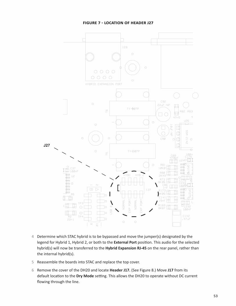
3 Locate Header J27 on the main PC board in the bottom of the chassis. Note this is located partially under the embedded PC board, and you may need to remove this as well for clear ac-cess. (You can typically pull the embedded PC board out of the way without removing all the cables.)
53
FigUre 7 - LoCATioN oF heAder j27
J27
4 Determine which STAC hybrid is to be bypassed and move the jumper(s) designated by the legend for Hybrid 1, Hybrid 2, or both to the External Port position. This audio for the selected hybrid(s) will now be transferred to the Hybrid Expansion RJ-45 on the rear panel, rather than the internal hybrid(s).
5 Reassemble the boards into STAC and replace the top cover.
6 Remove the cover of the DH20 and locate Header J17. (See Figure 8.) Move J17 from its default location to the Dry Mode setting. This allows the DH20 to operate without DC current flowing through the line.

54
FigUre 8 - LoCATioN oF heAder j17
J17
7 Connect Pins 1 & 25 on the DB-25 Connector located on the DH20 rear panel. This allows the DH20 to remain On Line at all times.
8 Create a cable to connect between STAC and the DH20. STAC connection will require an RJ-45 (8 position) plug and the DH20 will require an RJ-11 (6 position) plug. This can often be built easily by grafting a telephone cable to an Ethernet style CAT5 cable. Note: If bypassing both hybrids, a pigtail-style cable can be created, connecting the RJ-45 jack to two RJ-11 jacks. This cable is available from Comrex. Contact us for details.
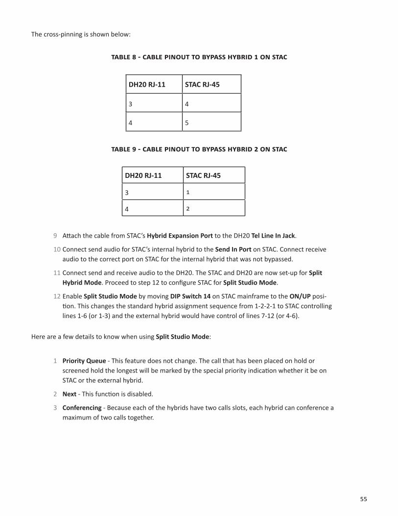
55
The cross-pinning is shown below:
TAbLe 8 - CAbLe piNoUT To bypASS hybrid 1 oN STAC
DH20 RJ-11 STAC RJ-45
3 4
4 5
TAbLe 9 - CAbLe piNoUT To bypASS hybrid 2 oN STAC
DH20 RJ-11 STAC RJ-45
3 1
4 2
9 Attach the cable from STAC’s Hybrid Expansion Port to the DH20 Tel Line In Jack.
10 Connect send audio for STAC’s internal hybrid to the Send In Port on STAC. Connect receive audio to the correct port on STAC for the internal hybrid that was not bypassed.
11 Connect send and receive audio to the DH20. The STAC and DH20 are now set-up for Split Hybrid Mode. Proceed to step 12 to configure STAC for Split Studio Mode.
12 Enable Split Studio Mode by moving DIP Switch 14 on STAC mainframe to the ON/UP posi-tion. This changes the standard hybrid assignment sequence from 1-2-2-1 to STAC controlling lines 1-6 (or 1-3) and the external hybrid would have control of lines 7-12 (or 4-6).
Here are a few details to know when using Split Studio Mode:
1 Priority Queue - This feature does not change. The call that has been placed on hold or screened hold the longest will be marked by the special priority indication whether it be on STAC or the external hybrid.
2 Next - This function is disabled.
3 Conferencing - Because each of the hybrids have two calls slots, each hybrid can conference a maximum of two calls together.
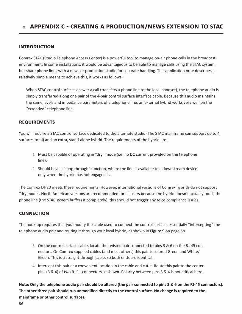
56
x. AppeNdix C - CreATiNg A prodUCTioN/NeWS exTeNSioN To STAC
iNTrodUCTioN
Comrex STAC (Studio Telephone Access Center) is a powerful tool to manage on-air phone calls in the broadcast environment. In some installations, it would be advantageous to be able to manage calls using the STAC system, but share phone lines with a news or production studio for separate handling. This application note describes a relatively simple means to achieve this, it works as follows:
When STAC control surfaces answer a call (transfers a phone line to the local handset), the telephone audio is simply transferred along one pair of the 4-pair control surface interface cable. Because this audio maintains the same levels and impedance parameters of a telephone line, an external hybrid works very well on the “extended” telephone line.
reqUireMeNTS
You will require a STAC control surface dedicated to the alternate studio (The STAC mainframe can support up to 4 surfaces total) and an extra, stand-alone hybrid. The requirements of the hybrid are:
1 Must be capable of operating in “dry” mode (i.e. no DC current provided on the telephone line).
2 Should have a “loop through” function, where the line is available to a downstream device only when the hybrid has not engaged it.
The Comrex DH20 meets these requirements. However, international versions of Comrex hybrids do not support “dry mode”. North American versions are recommended for all users because the hybrid doesn’t actually touch the phone line (the STAC system buffers it completely), this should not trigger any telco compliance issues.
CoNNeCTioN
The hook-up requires that you modify the cable used to connect the control surface, essentially “intercepting” the telephone audio pair and routing it through your local hybrid, as shown in Figure 9 on page 58.
3 On the control surface cable, locate the twisted pair connected to pins 3 & 6 on the RJ-45 con-nectors. On Comrex supplied cables (and most others) this pair is colored Green and White/Green. This is a straight-through cable, so both ends are identical.
4 Intercept this pair at a convenient location in the cable and cut it. Route this pair to the center pins (3 & 4) of two RJ-11 connectors as shown. Polarity between pins 3 & 4 is not critical here.
Note: Only the telephone audio pair should be altered (the pair connected to pins 3 & 6 on the RJ-45 connectors). The other three pair should run unmodified directly to the control surface. No change is required to the mainframe or other control surfaces.
57
operATioN
It is recommended that the control surface used in the alternate studio be configured for screener mode to avoid inadvertently putting calls to on-air state in the main studio. When the hybrid is off-line (not “seized”) the control surface will function as normal, with the ability to dial out on any available line, answer any call, and put them on hold. To transfer calls to the local hybrid, simply make sure the call is first in answer mode on the control surface (i.e. you can speak to the caller through the handset) by pressing the top button for that line, then engage the hybrid. The handset will go dead and the call will be available on the hybrid. If the handset is returned to the control surface cradle, the call will be dropped. When the hybrid is disengaged, the call will return to the handset. During this entire procedure the call will be locked out of other control surfaces and cannot be put on-air by the main studio.
Note: If a call is put On Hold in the alternate studio, the caller will hear the main On Hold audio, will participate in the Priority queue, and be subject to going On Air via the Next button if they reaches the top of the queue.

58
FigUre 9 - hooK-Up diAgrAM For prodUCTioN/NeWS exTeNSioN
AC POWER IN
SEND IN HOLD AUDIO IN AUX OUT HYBRID 1 OUT HYBRID 2 OUT
EXPANSIONPORT
7 - 9 10 - 12 7 - 9 10 - 12
1 - 3 1 - 34 - 6 4 - 6PHONE LINE IN LOOP-THRU OUT
CONTROL SURFACE1 2 3 4
SERIAL
VGA USB USB
HDMI
RESET
PRIMARYLAN
SECONDARYLAN
STAC Mainframe
RJ-45 to STAC Mainframe
8-WireEthernetCable
2-WireTelephoneCable
RJ-11to DH20“Line” Jack
Pin 4 Pin 3 Pin 4 Pin 3
RJ-11to DH20“Set” Jack
Line Set RJ-45 to STAC Control Surface
Pin 6 Pin 3
STAC Control Surface
DH20