Embed Size (px)
Citation preview
ISO 14001Registered
EnvironmentalManagement 015
ISO 9001Registered
QualityManagement 015
PRODUCT MANUAL
©AG
D S
yste
ms
Lim
ited
2016
Doc
. Ref
. 307
PM IS
S4
2
INTRODUCTION Product & technology 3
Key features 3 Product range 3 Typical applications 4 Product overview 4
INSTALLATION Mounting height, angles, clearance 5
Connecting power 6 Power & wiring 6-7 Power on test 7
USER CONFIGURATION Setting switch parameters 8 Rotary switch functions 8 Dip switch functions 9 Switch functions 10 RS422 Version - connecting the radar to a computer 11 RS422 Preparing the connection 11 Terminal setup 12-15 RS422 Test connection 16 RS422 Command examples 16 RS422 Command structure 17 RS422 Command list 18 RS422 Command details 19-21
TECHNICAL SPECIFICATIONS Product specification 22
HELP Troubleshooting 23-24
TRIAL AND EVALUATION Set up tools 25
MANUFACTURING TEST PROCESS Saturn test equipment 26
IMPORTANT SAFETY INFORMATION Safety precautions 27 Low power non-ionising radio transmission and safety 28
DISCLAIMER 32 Warranty 32
TABLE OF CONTENTS
3
INTRODUCTION
PRODUCT & TECHNOLOGY
KEY FEATURES
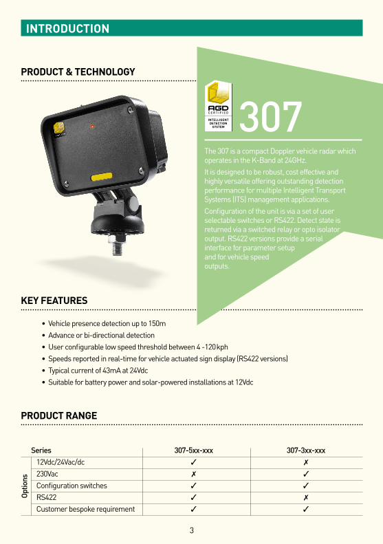
• Vehicle presence detection up to 150m • Advance or bi-directional detection • User configurable low speed threshold between 4 -120kph • Speeds reported in real-time for vehicle actuated sign display (RS422 versions) • Typical current of 43mA at 24Vdc • Suitable for battery power and solar-powered installations at 12Vdc
PRODUCT RANGE
Series 307-5xx-xxx 307-3xx-xxx12Vdc/24Vac/dc ✓ ✗
230Vac ✗ ✓
Configuration switches ✓ ✓
RS422 ✓ ✗
Customer bespoke requirement ✓ ✓
307The 307 is a compact Doppler vehicle radar which operates in the K-Band at 24GHz. It is designed to be robust, cost effective and highly versatile offering outstanding detection performance for multiple Intelligent Transport Systems (ITS) management applications. Configuration of the unit is via a set of user selectable switches or RS422. Detect state is returned via a switched relay or opto isolator output. RS422 versions provide a serial interface for parameter setup and for vehicle speed outputs.
Optio
ns
4
INTRODUCTION
TYPICAL APPLICATIONS
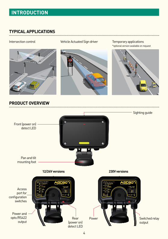
Intersection control Vehicle Actuated Sign driver Temporary applications *optional version available on request
PRODUCT OVERVIEW
Sighting guide
Rear (power on) detect LED
Front (power on)detect LED
Pan and tilt mounting foot
Access port for
configuration switches
Power and opto /RS422
output Power
230V versions12/24V versions
Switched relay output
5
INSTALLATION
MOUNTING HEIGHT, ANGLES, CLEARANCE
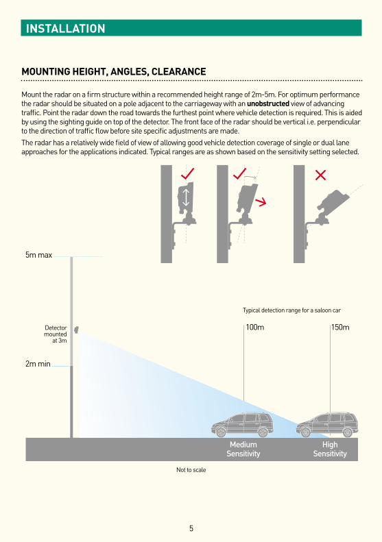
Mount the radar on a firm structure within a recommended height range of 2m-5m. For optimum performance the radar should be situated on a pole adjacent to the carriageway with an unobstructed view of advancing traffic. Point the radar down the road towards the furthest point where vehicle detection is required. This is aided by using the sighting guide on top of the detector. The front face of the radar should be vertical i.e. perpendicular to the direction of traffic flow before site specific adjustments are made.The radar has a relatively wide field of view of allowing good vehicle detection coverage of single or dual lane approaches for the applications indicated. Typical ranges are as shown based on the sensitivity setting selected.
5m max
2m min
100m 150m
MediumSensitivity
HighSensitivity
Typical detection range for a saloon car
Not to scale
Detectormounted
at 3m
6
POWER & WIRING
6 WAY 12/24Vdc & 24Vac
Wire Colour Function Power Off Power On No Detect Power On Detect
Red 12/24Vdc 24Vac
Black 0V 24Vac
White Opto Common
Yellow Opto N/O N/C N/O
Blue Opto N/C N/O N/C
10 WAY RS422 12/24Vdc & 24VacWire Colour Function Power Off Power On No Detect Power On Detect
Red 12/24Vdc 24Vac
Black 0V 24Vac
Green Ground
White Opto Common
Yellow Opto N/O N/C N/O
Blue Opto N/C N/O N/C
Brown RS422 RXA
Violet RS422 RXB
Orange RS422 TXZ
Pink RS422 TXY
INSTALLATION
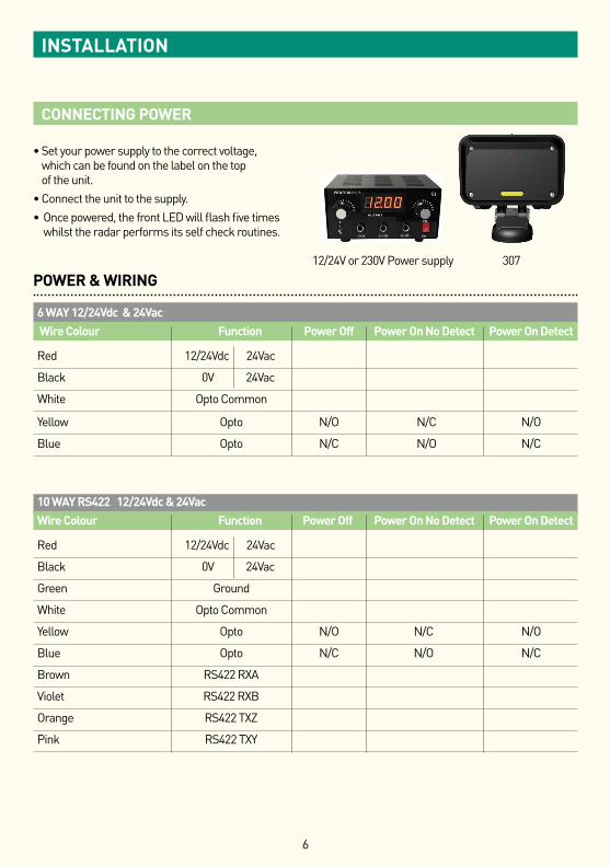
CONNECTING POWER
• Set your power supply to the correct voltage, which can be found on the label on the top of the unit.
• Connect the unit to the supply. • Once powered, the front LED will flash five times
whilst the radar performs its self check routines.
12/24V or 230V Power supply 307
7
POWER & WIRING (CONTINUED)
3+2 WAY 230VacWire Colour Function Power Off Power On No Detect Power On Detect
Brown 230Vac live
Blue 230Vac neutral
Red Relay common
Green Relay N/O N/C N/O
Blue Relay N/C N/O N/C
N/O = High Impedance switched output N/C = Low Impedance switched output Power Options 12Vdc 24Vdc 24Vac 230Vac*Switch only versions 84mA 43mA 35mA 16mARS422 plus switch versions 100mA 50mA 42mA N/ASupply Tolerances 10V -14Vdc 19V - 29Vdc 19V - 29Vac 90V - 264Vac
*Standard product safety rating 100 - 240Vac
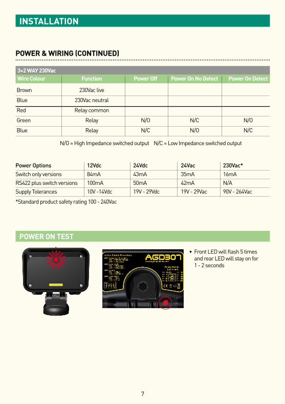
POWER ON TEST
• Front LED will flash 5 times and rear LED will stay on for 1 - 2 secondsZ
INSTALLATION
8
USER CONFIGURATION
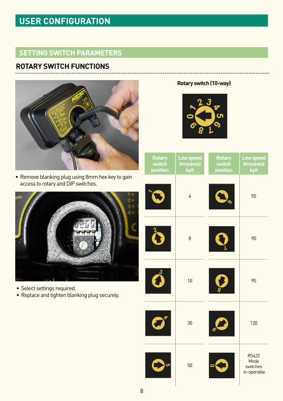
ROTARY SWITCH FUNCTIONS
Rotary switch (10-way)
01 2 3 4
56789
01 2 3 4
56789
01 2 3 4
56789
01 2 3 4
56789
01 2 3 4
56789
01 2 3 4
56789
01 2 3 4
56789
01 2 3 4
56789
01 2 3 4
56789
01 2 3 4
56789
01 2 3 4
56789
Rotary switch
position
Low speed threshold
kph
4
8
10
30
50
Rotary switch
position
Low speed threshold
kph
55
90
95
120
RS422 Mode
switches in-operable
01 2 3 4
56789
01 2 3 4
56789
01 2 3 4
56789
01 2 3 4
56789
01 2 3 4
56789
01 2 3 4
56789
01 2 3 4
56789
01 2 3 4
56789
01 2 3 4
56789
01 2 3 4
56789
01 2 3 4
56789
01 2 3 4
56789
01 2 3 4
56789
01 2 3 4
56789
01 2 3 4
56789
01 2 3 4
56789
01 2 3 4
56789
01 2 3 4
56789
01 2 3 4
56789
01 2 3 4
56789
01 2 3 4
56789
01 2 3 4
56789
01 2 3 4
56789
01 2 3 4
56789
01 2 3 4
56789
01 2 3 4
56789
01 2 3 4
56789
01 2 3 4
56789
01 2 3 4
56789
01 2 3 4
56789
01 2 3 4
56789
01 2 3 4
56789
01 2 3 4
56789
01 2 3 4
56789
01 2 3 4
56789
01 2 3 4
56789
01 2 3 4
56789
01 2 3 4
56789
01 2 3 4
56789
01 2 3 4
56789
01 2 3 4
56789
01 2 3 4
56789
01 2 3 4
56789
01 2 3 4
56789
01 2 3 4
56789
01 2 3 4
56789
01 2 3 4
56789
01 2 3 4
56789
01 2 3 4
56789
01 2 3 4
56789
01 2 3 4
56789
01 2 3 4
56789
01 2 3 4
56789
01 2 3 4
56789
01 2 3 4
56789
01 2 3 4
56789
01 2 3 4
56789
01 2 3 4
56789
01 2 3 4
56789
01 2 3 4
56789
01 2 3 4
56789
01 2 3 4
56789
01 2 3 4
56789
01 2 3 4
56789
01 2 3 4
56789
01 2 3 4
56789
01 2 3 4
56789
01 2 3 4
56789
01 2 3 4
56789
01 2 3 4
56789
01 2 3 4
56789
01 2 3 4
56789
01 2 3 4
56789
01 2 3 4
56789
01 2 3 4
56789
01 2 3 4
56789
01 2 3 4
56789
01 2 3 4
56789
01 2 3 4
56789
01 2 3 4
56789
01 2 3 4
56789
01 2 3 4
56789
01 2 3 4
56789
01 2 3 4
56789
01 2 3 4
56789
01 2 3 4
56789
01 2 3 4
56789
01 2 3 4
56789
01 2 3 4
56789
01 2 3 4
56789
01 2 3 4
56789
01 2 3 4
56789
01 2 3 4
56789
01 2 3 4
56789
01 2 3 4
56789
01 2 3 4
56789
01 2 3 4
56789
01 2 3 4
56789
01 2 3 4
56789
01 2 3 4
56789
01 2 3 4
56789
01 2 3 4
56789
01 2 3 4
56789
01 2 3 4
56789
01 2 3 4
56789
01 2 3 4
56789
01 2 3 4
56789
01 2 3 4
56789
01 2 3 4
56789
01 2 3 4
56789
SETTING SWITCH PARAMETERS
• Remove blanking plug using 8mm hex key to gain access to rotary and DIP switches.
• Select settings required. • Replace and tighten blanking plug securely.
9
USER CONFIGURATION
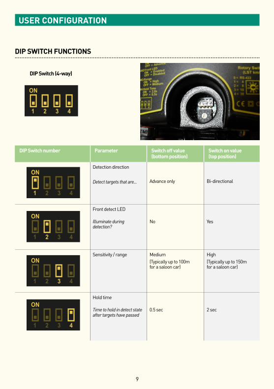
DIP SWITCH FUNCTIONS
DIP Switch (4-way)
DIP Switch number Parameter Switch off value (bottom position)
Switch on value (top position)
Detection direction
Detect targets that are... Advance only Bi-directional
Front detect LED Illuminate during detection?
No
Yes
Sensitivity / range Medium(Typically up to 100m for a saloon car)
High(Typically up to 150m for a saloon car)
Hold time Time to hold in detect state after targets have passed
0.5 sec
2 sec
ON
1 2 3 4
ON
1 2 3 4
ON
1 2 3 4
ON
ON
1 2 3 4
ON
1 2 3 4
1 2 3 4
ON
1 2 3 4
ON
1 2 3 4
ON
1 2 3 4
ON
1 2 3 4
ON
ON
1 2 3 4
ON
1 2 3 4
1 2 3 4
ON
1 2 3 4
ON
1 2 3 4
ON
1 2 3 4
ON
1 2 3 4
ON
ON
1 2 3 4
ON
1 2 3 4
1 2 3 4
ON
1 2 3 4
ON
1 2 3 4
ON
1 2 3 4
ON
1 2 3 4
ON
ON
1 2 3 4
ON
1 2 3 4
1 2 3 4
ON
1 2 3 4
ON
1 2 3 4
ON
1 2 3 4
ON
1 2 3 4
ON
ON
1 2 3 4
ON
1 2 3 4
1 2 3 4
ON
1 2 3 4
10
USER CONFIGURATION
SWITCH FUNCTIONS
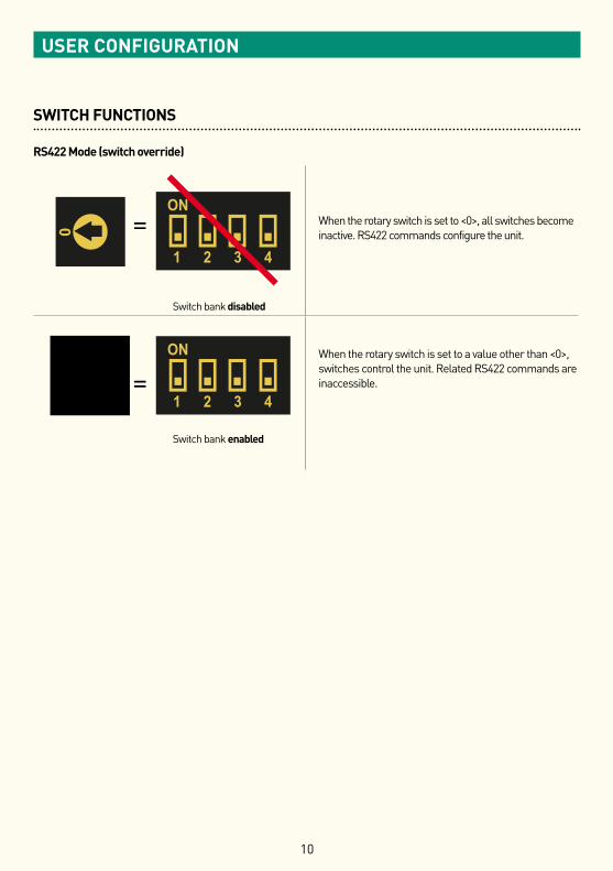
RS422 Mode (switch override)
=
Switch bank disabled
When the rotary switch is set to <0>, all switches become inactive. RS422 commands configure the unit.
=
Switch bank enabled
When the rotary switch is set to a value other than <0>, switches control the unit. Related RS422 commands are inaccessible.
ON
1 2 3 4
ON
1 2 3 4
ON
1 2 3 4
ON
ON
1 2 3 4
ON
1 2 3 4
1 2 3 4
ON
1 2 3 4
ON
1 2 3 4
ON
1 2 3 4
ON
1 2 3 4
ON
ON
1 2 3 4
ON
1 2 3 4
1 2 3 4
ON
1 2 3 4
01 2 3 4
56789
01 2 3 4
56789
01 2 3 4
56789
01 2 3 4
56789
01 2 3 4
56789
01 2 3 4
56789
01 2 3 4
56789
01 2 3 4
56789
01 2 3 4
56789
01 2 3 4
56789
01 2 3 4
56789
01 2 3 4
56789
01 2 3 4
56789
01 2 3 4
56789
01 2 3 4
56789
01 2 3 4
56789
01 2 3 4
56789
01 2 3 4
56789
01 2 3 4
56789
01 2 3 4
56789
01 2 3 4
56789
01 2 3 4
56789
11
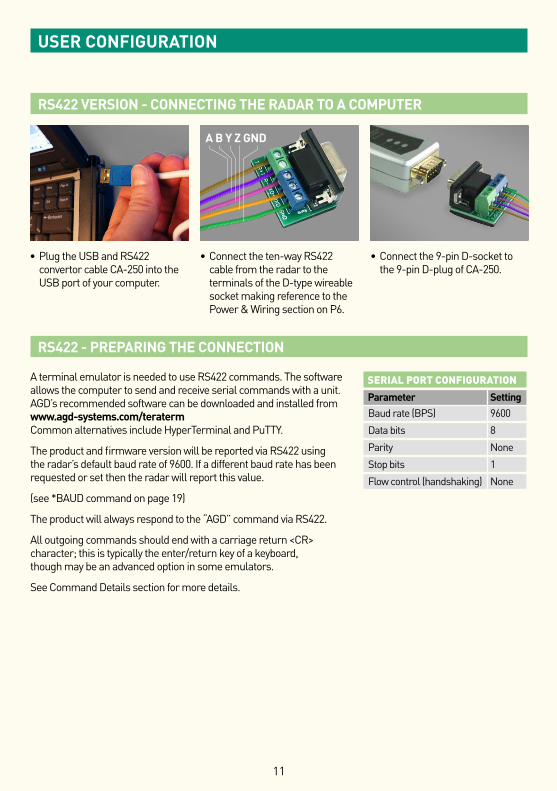
RS422 VERSION - CONNECTING THE RADAR TO A COMPUTER
RS422 - PREPARING THE CONNECTION
A terminal emulator is needed to use RS422 commands. The software allows the computer to send and receive serial commands with a unit. AGD’s recommended software can be downloaded and installed from www.agd-systems.com/teraterm Common alternatives include HyperTerminal and PuTTY.
The product and firmware version will be reported via RS422 using the radar’s default baud rate of 9600. If a different baud rate has been requested or set then the radar will report this value.
(see *BAUD command on page 19)
The product will always respond to the “AGD” command via RS422.
All outgoing commands should end with a carriage return <CR> character; this is typically the enter/return key of a keyboard, though may be an advanced option in some emulators.
See Command Details section for more details.
USER CONFIGURATION
A B Y Z GND
SERIAL PORT CONFIGURATION
Parameter Setting Baud rate (BPS) 9600
Data bits 8
Parity None
Stop bits 1
Flow control (handshaking) None
• Plug the USB and RS422 convertor cable CA-250 into the USB port of your computer.
• Connect the ten-way RS422 cable from the radar to the terminals of the D-type wireable socket making reference to the Power & Wiring section on P6.
• Connect the 9-pin D-socket to the 9-pin D-plug of CA-250.
12
USER CONFIGURATION
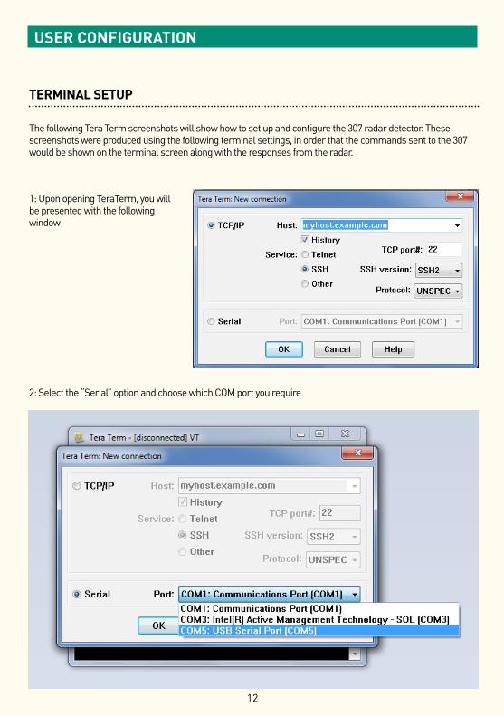
TERMINAL SETUP
The following Tera Term screenshots will show how to set up and configure the 307 radar detector. These screenshots were produced using the following terminal settings, in order that the commands sent to the 307 would be shown on the terminal screen along with the responses from the radar.
1: Upon opening TeraTerm, you will be presented with the following window
2: Select the “Serial” option and choose which COM port you require
13
USER CONFIGURATION
TERMINAL SETUP
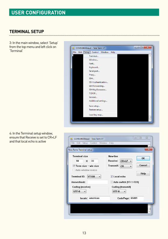
3: In the main window, select ‘Setup’ from the top menu and left click on ‘Terminal’
4: In the Terminal setup window, ensure that Receive is set to CR+LF and that local echo is active
14
USER CONFIGURATION
TERMINAL SETUP
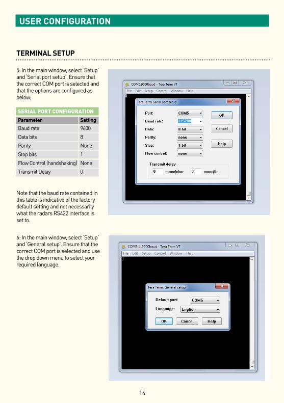
5: In the main window, select ‘Setup’ and ‘Serial port setup’. Ensure that the correct COM port is selected and that the options are configured as below;
Note that the baud rate contained in this table is indicative of the factory default setting and not necessarily what the radars RS422 interface is set to.
6: In the main window, select ‘Setup’ and ‘General setup’. Ensure that the correct COM port is selected and use the drop down menu to select your required language.
SERIAL PORT CONFIGURATION
Parameter Setting Baud rate 9600
Data bits 8
Parity None
Stop bits 1
Flow Control (handshaking) None
Transmit Delay 0
15
USER CONFIGURATION
TERMINAL SETUP
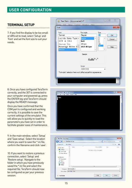
7: If you find the display to be too small or difficult to read, select ‘Setup’ and ‘Font’ and set the font size to suit your needs.
8: Once you have configured TeraTerm correctly, and the 307 is connected to your computer and powered up, press the ENTER key and TeraTerm should display the READY message.Once you have confirmed that the COM port is configured and working correctly, it is possible to save the current settings of the emulator. This will allow you to quickly re-load the parameters you have set in order to facilitate greater ease of maintenance.
9: In the main window, select ‘Setup’ and ‘Save setup’. Select the location where you want to save the *.ini file, confirm the filename and click ‘save’.
10: If you want to restore a previous connection, select ‘Setup’ and ‘Restore setup’. Navigate to the folder in which you have previously saved the *.ini file and select the required file. TeraTerm should now be configured as per your previous session.
16
USER CONFIGURATION
TEST CONNECTION
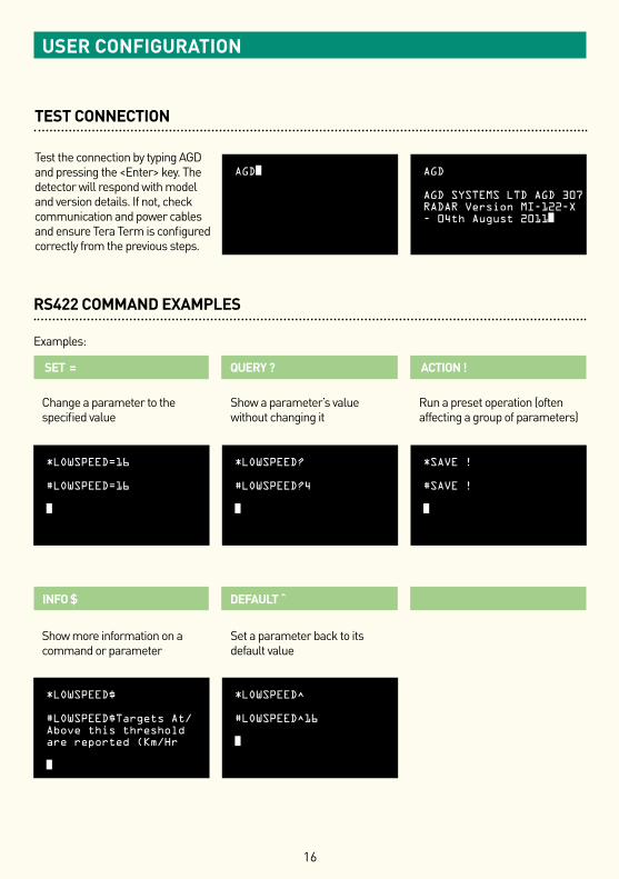
Test the connection by typing AGD and pressing the <Enter> key. The detector will respond with model and version details. If not, check communication and power cables and ensure Tera Term is configured correctly from the previous steps.
AGD■ AGD
AGD SYSTEMS LTD AGD 307 RADAR Version MI-122-X - 04th August 2011■
RS422 COMMAND EXAMPLES
Examples:
SET = QUERY ? ACTION !
INFO $ DEFAULT
Change a parameter to the specified value
Show more information on a command or parameter
Show a parameter’s value without changing it
Set a parameter back to its default value
Run a preset operation (often affecting a group of parameters)
*LOWSPEED=16
#LOWSPEED=16
■
*LOWSPEED$
#LOWSPEED$Targets At/Above this threshold are reported (Km/Hr
■
*LOWSPEED?
#LOWSPEED?4
■
*LOWSPEED^
#LOWSPEED^16
■
*SAVE !
#SAVE !
■
17
USER CONFIGURATION
RS422 COMMAND STRUCTURE
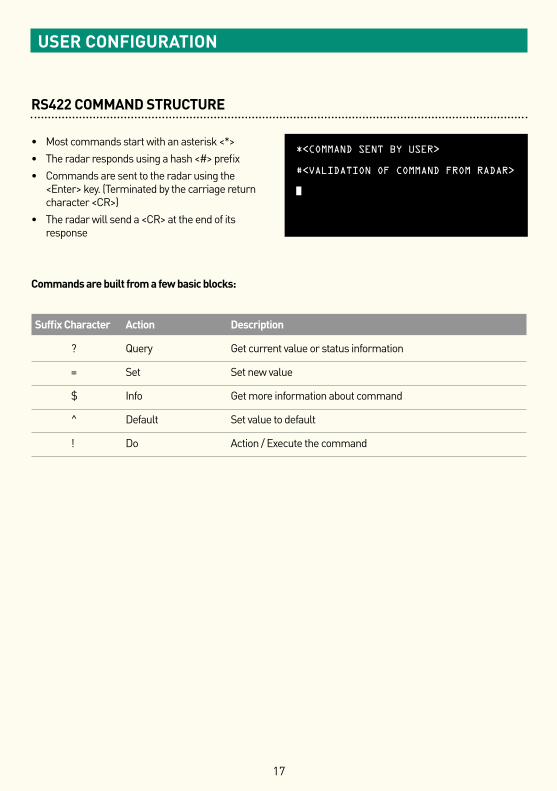
• Most commands start with an asterisk <*> • The radar responds using a hash <#> prefix• Commands are sent to the radar using the
<Enter> key. (Terminated by the carriage return character <CR>)
• The radar will send a <CR> at the end of its response
Commands are built from a few basic blocks:
Suffix Character Action Description
? Query Get current value or status information
= Set Set new value
$ Info Get more information about command
Default Set value to default
! Do Action / Execute the command
*<COMMAND SENT BY USER>
#<VALIDATION OF COMMAND FROM RADAR>
■
18
USER CONFIGURATION
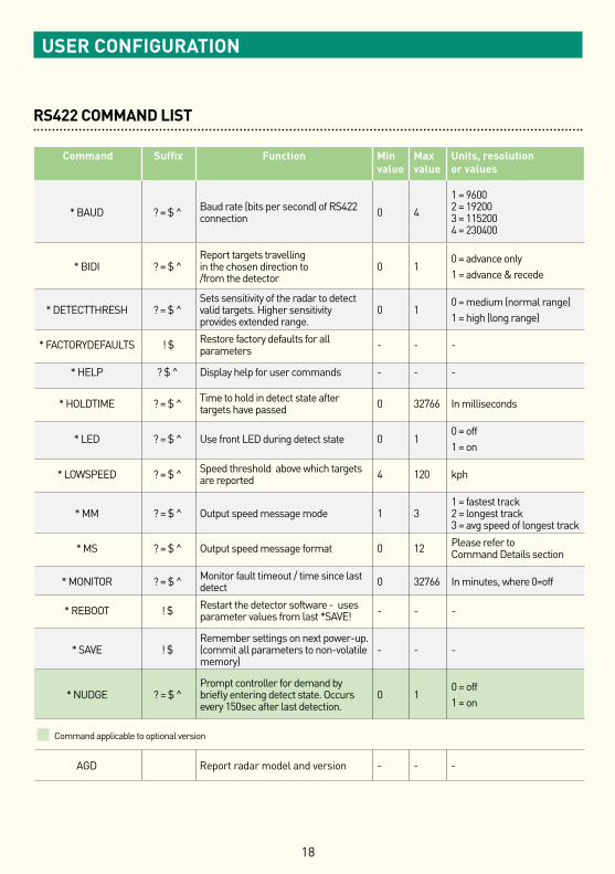
RS422 COMMAND LIST
Command Suffix Function Minvalue
Maxvalue
Units, resolution or values
* BAUD ? = $ Baud rate (bits per second) of RS422 connection 0 4
1 = 9600 2 = 19200 3 = 115200 4 = 230400
* BIDI ? = $ Report targets travelling in the chosen direction to /from the detector
0 10 = advance only1 = advance & recede
* DETECTTHRESH ? = $ Sets sensitivity of the radar to detect valid targets. Higher sensitivity provides extended range.
0 10 = medium (normal range)1 = high (long range)
* FACTORYDEFAULTS ! $ Restore factory defaults for all parameters - - -
* HELP ? $ Display help for user commands - - -
* HOLDTIME ? = $ Time to hold in detect state after targets have passed 0 32766 In milliseconds
* LED ? = $ Use front LED during detect state 0 10 = off1 = on
* LOWSPEED ? = $ Speed threshold above which targets are reported 4 120 kph
* MM ? = $ Output speed message mode 1 31 = fastest track 2 = longest track 3 = avg speed of longest track
* MS ? = $ Output speed message format 0 12 Please refer to Command Details section
* MONITOR ? = $ Monitor fault timeout / time since last detect 0 32766 In minutes, where 0=off
* REBOOT ! $ Restart the detector software - uses parameter values from last *SAVE! - - -
* SAVE ! $Remember settings on next power-up. (commit all parameters to non-volatile memory)
- - -
* NUDGE ? = $ Prompt controller for demand by briefly entering detect state. Occurs every 150sec after last detection.
0 10 = off1 = on
n Command applicable to optional version
AGD Report radar model and version - - -
19
USER CONFIGURATION
RS422 COMMAND DETAILS
AGDAll AGD detectors respond to the basic AGD command. Each unit will respond with specific model details and firmware version.
Typical response – AGD SYSTEMS LTD 307 Radar Version MI-122-X 30th August 2011
*BAUDThe RS422 output can operate at a number of baud rates. When setting a new baud rate, the unit will acknowledge the request at the current baud rate, before switching to the new value. A power-cycle or *REBOOT! command is not normally required after the *BAUD= command.
Typical response – #BAUD?1
*BIDIAn advancing target is one that travels towards the front-face of the detector. A receding target is one that travels away from the front-face. The 307 can be configured to report advancing targets only, or both advancing and receding targets. Note that this parameter is also accessible via the switch settings.
Typical response – #BIDI?0
*DETECTTHRESHSelect ‘0’ = medium setting (less sensitive i.e. shorter range typically 100m for a saloon car) or alternatively select ‘1’ = high setting (more sensitive i.e. longer range typically up to 150m for a saloon car). Note these settings are synonymous with the RS422 commands if using this option.
Typical response – #DETECTTHRESH?0
*FACTORYDEFAULTSThis command will set all parameters back to their default values and commit them to flash memory. A *SAVE! command is not required after issuing this command.
Typical response – #FACTORYDEFAULTS!Done
*HELPThis displays a table of valid commands along with a short description of each.
Typical response – #HELP...
*HOLDTIMEHold Time states how long the unit stays in detect after the target has left its field of view. Hold Time is expressed in milliseconds, where 1000ms = 1s. Note that this parameter is also accessible via the switch settings.
Typical response – #HOLDTIME?500
20
USER CONFIGURATION
RS422 COMMAND DETAILS
*LEDThis command will determine whether the front LED is illuminated during a detect state. Note that this parameter is also accessible via the switch settings.
Typical response – #LED?0 where 0 = off and 1 = on
*LOWSPEEDThis command accesses the Low Speed threshold/cutoff in kph. The radar will ignore targets travelling below this value, and respond when a target is detected above this speed.
Typical response – #LOWSPEED?33
*MMThis command states which value to output over an RS422 connection, where:1 = Instantaneous speed of the fastest target 2 = Current speed of the oldest/longest target tracked (recommended) 3 = Average speed of the of the oldest/longest target tracked
Typical response – #MM?1
*MSThis command dictates how the radar reports targets over an RS422 connection. It offers a number of speed message formats at varying Frames Per Second (fps), or one per detect state. Note that ‘d’ represents a decimal digit and ‘x’, a Hex character: 0 none 1 DCFMSxx.xx 20 fps 2 dd 20 fps 3 *Sddd 20 fps 4 DCFMSxx.xx 10 fps 5 dd 10 fps 6 *Sddd 10 fps 7 DCFMSxx.xx 5 fps 8 dd 5 fps 9 *Sddd 5 fps 10 DCFMSxx.xx one per detect state 11 dd one per detect state 12 000,0000000000,A,ddd,-,-,-,-,-,-,- once per second
21
USER CONFIGURATION
RS422 COMMAND DETAILS
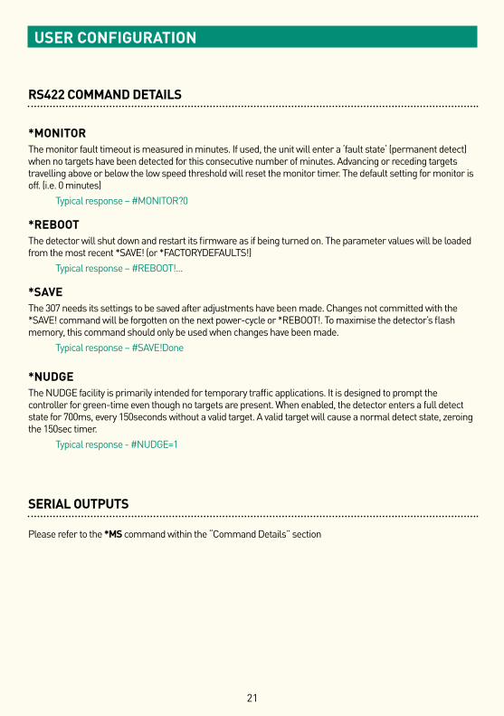
*MONITORThe monitor fault timeout is measured in minutes. If used, the unit will enter a ‘fault state‘ (permanent detect) when no targets have been detected for this consecutive number of minutes. Advancing or receding targets travelling above or below the low speed threshold will reset the monitor timer. The default setting for monitor is off. (i.e. 0 minutes)
Typical response – #MONITOR?0
*REBOOTThe detector will shut down and restart its firmware as if being turned on. The parameter values will be loaded from the most recent *SAVE! (or *FACTORYDEFAULTS!)
Typical response – #REBOOT!...
*SAVEThe 307 needs its settings to be saved after adjustments have been made. Changes not committed with the *SAVE! command will be forgotten on the next power-cycle or *REBOOT!. To maximise the detector’s flash memory, this command should only be used when changes have been made.
Typical response – #SAVE!Done
*NUDGEThe NUDGE facility is primarily intended for temporary traffic applications. It is designed to prompt the controller for green-time even though no targets are present. When enabled, the detector enters a full detect state for 700ms, every 150seconds without a valid target. A valid target will cause a normal detect state, zeroing the 150sec timer.
Typical response - #NUDGE=1
SERIAL OUTPUTS
Please refer to the *MS command within the “Command Details” section
RoHS COMPLIANTRestriction on Hazardous Substances
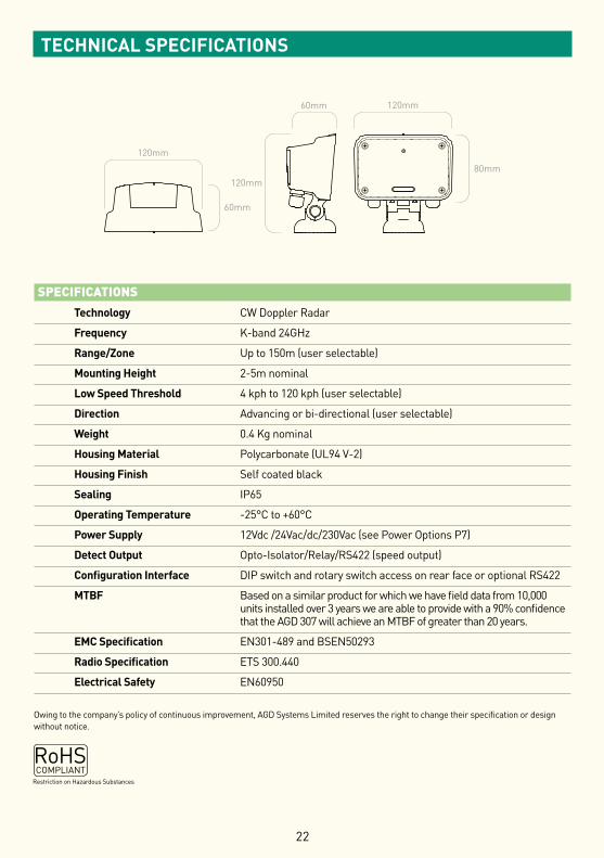
SPECIFICATIONS
Technology CW Doppler Radar
Frequency K-band 24GHz
Range/Zone Up to 150m (user selectable)
Mounting Height 2-5m nominal
Low Speed Threshold 4 kph to 120 kph (user selectable)
Direction Advancing or bi-directional (user selectable)
Weight 0.4 Kg nominal
Housing Material Polycarbonate (UL94 V-2)
Housing Finish Self coated black
Sealing IP65
Operating Temperature -25°C to +60°C
Power Supply 12Vdc /24Vac/dc/230Vac (see Power Options P7)
Detect Output Opto-Isolator/Relay/RS422 (speed output)
Configuration Interface DIP switch and rotary switch access on rear face or optional RS422
MTBF Based on a similar product for which we have field data from 10,000 units installed over 3 years we are able to provide with a 90% confidence that the AGD 307 will achieve an MTBF of greater than 20 years.
EMC Specification EN301-489 and BSEN50293
Radio Specification ETS 300.440
Electrical Safety EN60950
Owing to the company’s policy of continuous improvement, AGD Systems Limited reserves the right to change their specification or design without notice.
60mm
120mm
120mm
80mm120mm
60mm
22
TECHNICAL SPECIFICATIONS
23
HELP
TROUBLESHOOTING
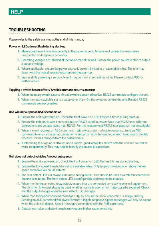
Please refer to the safety warning at the end of this manual.
Power on LEDs do not flash during start-up1. Make sure the unit is wired correctly to the power source. An incorrect connection may cause
unexpected or dangerous behaviour.2. Operating voltages are labelled at the top or rear of the unit. Ensure the power source is able to output
a suitable voltage.3. Where applicable, ensure the power source is current limited to a reasonable value. The unit may
draw twice the typical operating current during start-up.4. Successfully powering a servicable unit may confirm a fault with another. Please contact AGD for
further advice.
Toggling a switch has no effect / A valid command returns an error1. When the rotary switch is set to <0>, all switches become inactive. RS422 commands configure the unit.2. When the rotary switch is set to a value other than <0>, the switches control the unit. Related RS422
commands are inaccessible.
Unit will not output on RS422 connection1. Ensure the unit is powered on. Check the front power-on LED flashes 5 times during start-up.2. Ensure the detector is wired correctly into an RS422 serial interface. Note that RS232 uses different
connections and voltage levels than RS422. For this reason most RS232 interfaces will not be suitable.3. When the unit receives an AGD command it will always return a legible response. Send an AGD
command to ensure the serial connection is setup correctly. Try sending at each baud rate to identify whether unit has changed from the default value.
4. If interfacing to a sign or controller, use a known-good laptop to confirm both the unit and controller work independently. This may help to identify the source of a problem.
Unit does not detect vehicles / not output speeds1. Ensure the unit is powered on. Check the front power-on LED flashes 5 times during start-up.2. Ensure the low speed threshold is set to a suitable value. Only targets travelling at or above the low
speed threshold will cause detects.3. The rear detect LED will always illuminate during detect. This should be used as a reference for when
the unit is in detect. The front detect LED is configurable and may not be enabled.4. When monitoring an opto / relay output, ensure they are connected correctly to external equipment.
The common line must always be used whether normally open or normally closed is required. Check that the outputs toggle when the rear detect LED changes.
5. When monitoring RS422 speed message outputs, ensure the serial connection is setup correctly. Sending an AGD command will always prompt a legible response. Speed messages will only be output when the unit is in detect. Speed messages are enabled with the *MS command.
6. Detecting smaller or distant targets may require higher radar sensitivity.
24
HELP
TROUBLESHOOTING
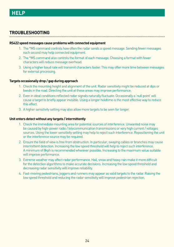
RS422 speed messages cause problems with connected equipment1. The *MS command controls how often the radar sends a speed message. Sending fewer messages
each second may help connected equipment.2. The *MS command also controls the format of each message. Choosing a format with fewer
characters will reduce message overhead.3. Using a higher baud rate will transmit characters faster. This may offer more time between messages
for external processing.
Targets occasionally drop / gap during approach1. Check the mounting height and alignment of the unit. Radar sensitivity might be reduced at dips or
bends in the road. Directing the unit at these areas may improve performance.2. Even in ideal conditions reflected radar signals naturally fluctuate. Occasionally a ‘null point’ will
cause a target to briefly appear invisible. Using a longer holdtime is the most effective way to reduce this effect.
3. A higher sensitivity setting may also allow more targets to be seen for longer.
Unit enters detect without any targets / intermittently1. Check the immediate mounting area for potential sources of interference. Unwanted noise may
be caused by high-power radio / telecommunication transmissions or very high current / voltages sources. Using the lower sensitivity setting may help to reject such interference. Repositioning the unit or the interference source may be required.
2. Ensure the field of view is free from obstruction. In particular, swaying cables or branches may cause intermittent detection. Increasing the low speed threshold will help to reject such interference. A minimum of 8kph is recommended wherever possible. Increasing to the maximum value suitable will improve performance.
3. Extreme weather may affect radar performance. Hail, snow and heavy rain make it more difficult for the detection algorithms to make accurate decisions. Increasing the low speed threshold and decreasing radar sensitivity will improve reliability.
4. Fast-moving pedestrians, joggers and runners may appear as valid targets to the radar. Raising the low speed threshold and reducing the radar sensitivity will improve pedestrian rejection.
25
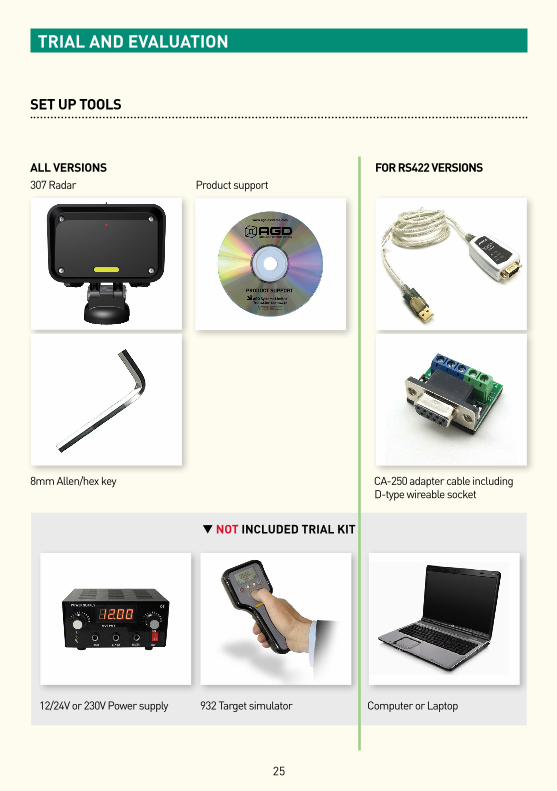
SET UP TOOLS
ALL VERSIONS FOR RS422 VERSIONS307 Radar Product support
8mm Allen/hex key CA-250 adapter cable including D-type wireable socket
▼ NOT INCLUDED TRIAL KIT
12/24V or 230V Power supply 932 Target simulator Computer or Laptop
TRIAL AND EVALUATION
26
MANUFACTURING TEST PROCESS
LIFETIME PRODUCT TRACEABILITY There are clearly defined pass and fail criteria at all stages within the Saturn test process. The test results in association with the product build revision are recorded on a product serial number basis. The full suite of test measurements is instantly sent to the dedicated product database within the AGD secure server facility, providing full traceability during the product lifetime.
The AGD Certified symbol is your mark of assured performance.
TEST EQUIPMENT:
TEST FUNCTION:
PRODUCT TEST: SATURN was designed and developed by AGD Systems
SATURN INTELLIGENT DETECTION SYSTEMS
307 | 308 | 330
• Simulated speed range 4-200 kph• Signal size and direction control
• Optimisation of frequency signals• Test cycle time 7 minutes
• Simulated speed range 4-200 kph• Signal size and direction control
• Optimisation of frequency signals• Test cycle time 7 minutes
SATURN was designed and developed by AGD Systems
TM
SATURNTM
307 | 308 | 330
TEST EQUIPMENT:
TEST FUNCTION:
PRODUCT TEST:
INTELLIGENT DETECTION SYSTEMS
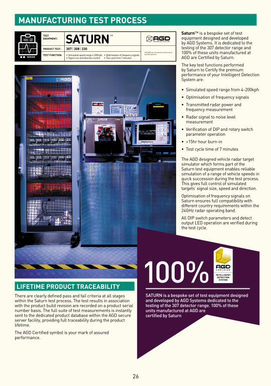
Saturn™ is a bespoke set of test equipment designed and developed by AGD Systems. It is dedicated to the testing of the 307 detector range and 100% of these units manufactured at AGD are Certified by Saturn.
The key test functions performed by Saturn to Certify the premium performance of your Intelligent Detection System are:
• Simulated speed range from 4-200kph
• Optimisation of frequency signals
• Transmitted radar power and frequency measurement
• Radar signal to noise level measurement
• Verification of DIP and rotary switch parameter operation
• >15hr hour burn-in
• Test cycle time of 7 minutes
The AGD designed vehicle radar target simulator which forms part of the Saturn test equipment enables reliable simulation of a range of vehicle speeds in quick succession during the test process. This gives full control of simulated targets’ signal size, speed and direction.
Optimisation of frequency signals on Saturn ensures full compatibility with different country requirements within the 24GHz radar operating band.
All DIP switch parameters and detect output LED operation are verified during the test cycle.
100%SATURN is a bespoke set of test equipment designed and developed by AGD Systems dedicated to the testing of the 307 detector range. 100% of these units manufactured at AGD are certified by Saturn
27
IMPORTANT SAFETY INFORMATION
SAFETY PRECAUTIONS
All work must be performed in accordance with company working practices, in-line with adequate risk assessments. Only skilled and instructed persons should carry out work with the product. Experience and safety procedures in the following areas may be relevant:
• Working with mains power • Working with modern electronic/electrical equipment • Working at height • Working at the roadside or highways
1. This product is compliant to the Restriction of Hazardous Substances (RoHS - European Union directive 2011/65/EU).
2. Should the product feature user-accessible switches, an access port will be provided. Only the specified access port should be used to access switches. Only non-conductive tools are to be used when operating switches.
3. The product must be correctly connected to the specified power supply. All connections must be made whilst the power supply is off or suitably isolated. Safety must take always take precedence and power must only be applied when deemed safe to do so.
4. No user-maintainable parts are contained within the product. Removing or opening the outer casing is deemed dangerous and will void all warranties.
5. Under no circumstances should a product suspected of damage be powered on. Internal damage may be suggested by unusual behaviour, an unusual odour or damage to the outer casing. Please contact AGD for further advice.
28
IMPORTANT SAFETY INFORMATION
LOW POWER NON-IONISING RADIO TRANSMISSION AND SAFETY
Concern has been expressed in some quarters that low power radio frequency transmission may constitute a health hazard. The transmission characteristics of low power radio devices is a highly regulated environment for the assurance of safe use.
There are strict limits on continuous emission power levels and these are reflected in the testing specifications that the products are approved to. These type approval limits are reflected in the product specifications required for a typical geographic area such as those for the EU (ETS300:440), for the USA (FCC part 15c) and for Australia/New Zealand (AS/NZS 4268). The limits adopted in these specifications are typically replicated in many other localized specifications.
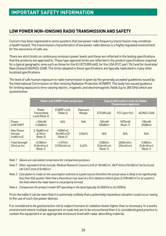
The level of safe human exposure to radio transmission is given by the generally accepted guidelines issued by the International Commission on Non-Ionizing Radiation Protection (ICNIRP). This body has issued guidance for limiting exposure to time-varying electric, magnetic and electromagnetic fields (up to 300 GHz) which are quoted below.
Note 1 Values are calculated conversions for comparison purposes.
Note 2 Other equivalent limits include; Medical Research Council Limit of 10mW/cm2, IACP limit of 5mW/cm2 (at 5cm) and UK CAST limit of 5mW/cm2
Note 3 Calculation is made on the assumption antenna is a point source therefore the actual value is likely to be significantly less than that quoted. Note that a theoretical max level at a 5cm distance (which gives 0.318mW/cm2) is at a point in the field where the radar beam is not properly formed.
Note 4 Comparison for product model 307 operating in the band typically 24.050GHz to 24.250GHz
From the table it can be seen that it is extremely unlikely that a potentially hazardous situation could occur owing to the use of such low power devices.
It is considered to be good practice not to subject humans to radiation levels higher than is necessary. In a works environment where multiple equipment on soak test are to be encountered then it is considered good practice to contain the equipment in an appropriate enclosure lined with radar absorbing material.
Radar and ICNIRP limit comparison Typical Informative Limits for Radar Transmission Approval
Radar Transmitted
Level (Note 4)
ICNIRP Limit (Table 6)
Exposure Margin
ETS300:440
FCC (part15c)
AS/NZS 4268
Power (mW EIRP)
<100mW (<20dBm)
N/A N/A 100mW (20dBm)
1875mW (Note 1)
100mW (20dBm)
Max Power Density (mW/cm2)
3.18µW/cm2 at 50cm (Note 3)
<50W/m2 (5mW/cm2)
(Note 2)
0.064%
N/A
N/A
N/A
Field Strength (V/m) at 3m
<0.58V/m (5.8mV/cm)
(Note 1)
<137V/m (1370mV/cm)
0.42%
0.58V/m (5.8mV/cm)
(Note 1)
2500mV/m (25mV/cm)
0.58V/m (5.8mV/cm)
(Note 1)

NOTES

NOTES

NOTES
DISCLAIMER
While we (AGD Systems) endeavour to keep the information in this manual correct at the time of print, we make no representations or warranties of any kind, express or implied, about the completeness, accuracy, reliability, suitability or availability with respect to the information, products, services, or related graphics contained herein for any purpose.
Any reliance you place on such information is therefore strictly at your own risk. In no event will we be liable for any loss or damage including without limitation, indirect or consequential loss or damage, or any loss or damage whatsoever arising from loss of data or profits arising out of, or in connection with, the use of this manual.
WARRANTY
All AGD products are covered by a 12 month return to factory warranty. Products falling outside this period may be returned to AGD Systems for evaluation, repair, update or re-calibration, any of which may be chargeable.
AGD Systems LimitedWhite Lion House T: +44 (0)1452 854212 Gloucester Road, F: +44 (0)1452 854213Staverton, Cheltenham E: [email protected], GL51 0TF, UK W: agd-systems.com
ISO 14001Registered
EnvironmentalManagement 015
ISO 9001Registered
QualityManagement 015 ©
AGD
Sys
tem
s Li
mite
d 20
16 D
oc. R
ef. 3
07 P
M IS
S4