Embed Size (px)
Citation preview
Product Manual ABB i-bus® EIBEIB Power Supply UnitsSV/S 30.320.5SV/S 30.640.5SU/S 30.640.1
Intelligent Installation Systems
2
Contents
Page
1 EIB Power Supply Units
1.1 Introduction . . . . . . . . . . . . . . . . . . . . . . . . . . . . . . . . . . . . . . . . . 41.2 The ABB product range . . . . . . . . . . . . . . . . . . . . . . . . . . . . . . . 4
2 SV/S 30.320.5EIB Power Supply, 320 mA, MDRC
2.1 General . . . . . . . . . . . . . . . . . . . . . . . . . . . . . . . . . . . . . . . . . . . . . 62.1.1 Product and functional description . . . . . . . . . . . . . . . . . . . . . . . . 6
2.2 Device technology . . . . . . . . . . . . . . . . . . . . . . . . . . . . . . . . . . . . 62.2.1 Technical data . . . . . . . . . . . . . . . . . . . . . . . . . . . . . . . . . . . . . . . . 62.2.2 Device connection . . . . . . . . . . . . . . . . . . . . . . . . . . . . . . . . . . . . . 72.2.3 Dimension drawing . . . . . . . . . . . . . . . . . . . . . . . . . . . . . . . . . . . . 72.2.4 Installation and commissioning . . . . . . . . . . . . . . . . . . . . . . . . . . . 7
2.3 Planning and application . . . . . . . . . . . . . . . . . . . . . . . . . . . . . . 82.3.1 Device application . . . . . . . . . . . . . . . . . . . . . . . . . . . . . . . . . . . . . 8
2.4 Function and operation . . . . . . . . . . . . . . . . . . . . . . . . . . . . . . . 82.4.1 Reset . . . . . . . . . . . . . . . . . . . . . . . . . . . . . . . . . . . . . . . . . . . . . . . 82.4.2 Fault . . . . . . . . . . . . . . . . . . . . . . . . . . . . . . . . . . . . . . . . . . . . . . . . 8
3 SV/S 30.640.5EIB Power Supply, 640 mA, MDRC
3.1 General . . . . . . . . . . . . . . . . . . . . . . . . . . . . . . . . . . . . . . . . . . . . . 103.1.1 Product and functional description . . . . . . . . . . . . . . . . . . . . . . . . 10
3.2 Device technology . . . . . . . . . . . . . . . . . . . . . . . . . . . . . . . . . . . . 103.2.1 Technical data . . . . . . . . . . . . . . . . . . . . . . . . . . . . . . . . . . . . . . . . 103.2.2 Device connection . . . . . . . . . . . . . . . . . . . . . . . . . . . . . . . . . . . . . 113.2.3 Dimension drawing . . . . . . . . . . . . . . . . . . . . . . . . . . . . . . . . . . . . 113.2.4 Installation and commissioning . . . . . . . . . . . . . . . . . . . . . . . . . . . 11
3.3 Planning and application . . . . . . . . . . . . . . . . . . . . . . . . . . . . . . 123.3.1 Device application . . . . . . . . . . . . . . . . . . . . . . . . . . . . . . . . . . . . . 123.3.2 Application example . . . . . . . . . . . . . . . . . . . . . . . . . . . . . . . . . . . 12
3.4 Function and operation . . . . . . . . . . . . . . . . . . . . . . . . . . . . . . . 133.4.1 Reset . . . . . . . . . . . . . . . . . . . . . . . . . . . . . . . . . . . . . . . . . . . . . . . 133.4.2 Fault . . . . . . . . . . . . . . . . . . . . . . . . . . . . . . . . . . . . . . . . . . . . . . . . 13
4 SU/S 30.640.1Uninterruptible EIB Power Supply, 640 mA, MDRC
4.1 General . . . . . . . . . . . . . . . . . . . . . . . . . . . . . . . . . . . . . . . . . . . . . 144.1.1 Product and functional description . . . . . . . . . . . . . . . . . . . . . . . . 14
4.2 Device technology . . . . . . . . . . . . . . . . . . . . . . . . . . . . . . . . . . . . 144.2.1 Technical data . . . . . . . . . . . . . . . . . . . . . . . . . . . . . . . . . . . . . . . . 144.2.2 Device connection . . . . . . . . . . . . . . . . . . . . . . . . . . . . . . . . . . . . . 154.2.3 Dimension drawing . . . . . . . . . . . . . . . . . . . . . . . . . . . . . . . . . . . . 164.2.4 Installation and commissioning . . . . . . . . . . . . . . . . . . . . . . . . . . . 16
3
Contents
Page
4.3 Planning and application . . . . . . . . . . . . . . . . . . . . . . . . . . . . . . 174.3.1 Device application . . . . . . . . . . . . . . . . . . . . . . . . . . . . . . . . . . . . . 174.3.2 Backup supply . . . . . . . . . . . . . . . . . . . . . . . . . . . . . . . . . . . . . . . . 174.3.3 Installation and connection of the Battery Module AM/S 12.1 . . . 184.3.4 Installation and connection of the sealed lead acid batteries
SAK7, SAK12, SAK17 . . . . . . . . . . . . . . . . . . . . . . . . . . . . . . . . . . 184.3.5 Connection of the potential-free changeover contact . . . . . . . . . . 19
4.4 Function and operation . . . . . . . . . . . . . . . . . . . . . . . . . . . . . . . 204.4.1 Reset . . . . . . . . . . . . . . . . . . . . . . . . . . . . . . . . . . . . . . . . . . . . . . . 204.4.2 Battery Life . . . . . . . . . . . . . . . . . . . . . . . . . . . . . . . . . . . . . . . . . . . 204.4.3 Fault . . . . . . . . . . . . . . . . . . . . . . . . . . . . . . . . . . . . . . . . . . . . . . . . 204.4.4 Diagnostics table . . . . . . . . . . . . . . . . . . . . . . . . . . . . . . . . . . . . . . 22
5 AM/S 12.1 Battery Module, 12 V DC, MDRC
5.1 General . . . . . . . . . . . . . . . . . . . . . . . . . . . . . . . . . . . . . . . . . . . . . 245.1.1 Product and functional description . . . . . . . . . . . . . . . . . . . . . . . . 24
5.2 Device technology . . . . . . . . . . . . . . . . . . . . . . . . . . . . . . . . . . . . 245.2.1 Technical data . . . . . . . . . . . . . . . . . . . . . . . . . . . . . . . . . . . . . . . . 245.2.2 Device connection . . . . . . . . . . . . . . . . . . . . . . . . . . . . . . . . . . . . . 255.2.3 Dimension drawing . . . . . . . . . . . . . . . . . . . . . . . . . . . . . . . . . . . . 25
5.3 Planning and application . . . . . . . . . . . . . . . . . . . . . . . . . . . . . . 265.3.1 Device application . . . . . . . . . . . . . . . . . . . . . . . . . . . . . . . . . . . . . 26
6 Sealed Lead Acid BatteriesSAK7, SAK12, SAK17
6.1 General . . . . . . . . . . . . . . . . . . . . . . . . . . . . . . . . . . . . . . . . . . . . . 286.1.1 Product and functional description . . . . . . . . . . . . . . . . . . . . . . . . 286.2 Device technology . . . . . . . . . . . . . . . . . . . . . . . . . . . . . . . . . . . . 286.2.1 Technical data for SAK7 . . . . . . . . . . . . . . . . . . . . . . . . . . . . . . . . 286.2.2 Technical data for SAK12 . . . . . . . . . . . . . . . . . . . . . . . . . . . . . . . 286.2.3 Technical data for SAK17 . . . . . . . . . . . . . . . . . . . . . . . . . . . . . . . 28
7 KS/K 4.1 and KS/K 2.1Cable Sets
7.1 General . . . . . . . . . . . . . . . . . . . . . . . . . . . . . . . . . . . . . . . . . . . . . 297.1.1 Product and functional description . . . . . . . . . . . . . . . . . . . . . . . . 29
7.2 Device technology . . . . . . . . . . . . . . . . . . . . . . . . . . . . . . . . . . . . 297.2.1 Technical data for Cable Set Basic KS/K 4.1 . . . . . . . . . . . . . . . . 297.2.2 Technical data for Cable Set Extension KS/K 2.1 . . . . . . . . . . . . . 29
8 Appendix
8.1 Ordering information . . . . . . . . . . . . . . . . . . . . . . . . . . . . . . . . . . 308.1.1 EIB power supply units . . . . . . . . . . . . . . . . . . . . . . . . . . . . . . . . . 308.1.2 Batteries and accessories . . . . . . . . . . . . . . . . . . . . . . . . . . . . . . . 30
4
ABB i-bus® EIB EIB Power Supply Units
1 EIB Power SupplyUnits
1.1 Introduction
1.2 The ABB product range
EIB power supply units produce the EIB system voltage to supply theconnected EIB components with power and over which EIB telegrams aretransmitted.
To isolate the telegram traffic from the supply voltage, the EIB power supply units are decoupled from the bus line by an integrated choke. The busline is disconnected from the supply with a reset during which all the devicesconnected to the bus line are returned to their initial state.
Fluctuations and failure of the bus voltage can lead to the loss of telegramsand faults in the installation. The EIB bus voltage should therefore alwayshave a backup supply in critical applications, e.g., security functions.
ABB offers a co-ordinated range of EIB power supply units and batteries toprovide a professional back-up supply, whether for small systems in detachedhouses, for larger installations in trade and commercial applications or forsophisticated requirements in office buildings, industrial premises, hotels andhospitals.
All the EIB power supply units from ABB contain an integrated choke.The connection to the ABB i-bus® EIB is established via a bus connectionterminal.
ABB offers three different EIB power supply units as DIN rail mounted devi-ces for various applications:
1. SV/S 30.320.5EIB Power Supply, 320 mA, MDRC
2. SV/S 30.640.5EIB Power Supply, 640 mA, MDRC
3. SU/S 30.640.1Uninterruptible EIB Power Supply, 640 mA, MDRC
These three EIB power supply units are compared in the following table.
5
ABB i-bus® EIB EIB Power Supply Units
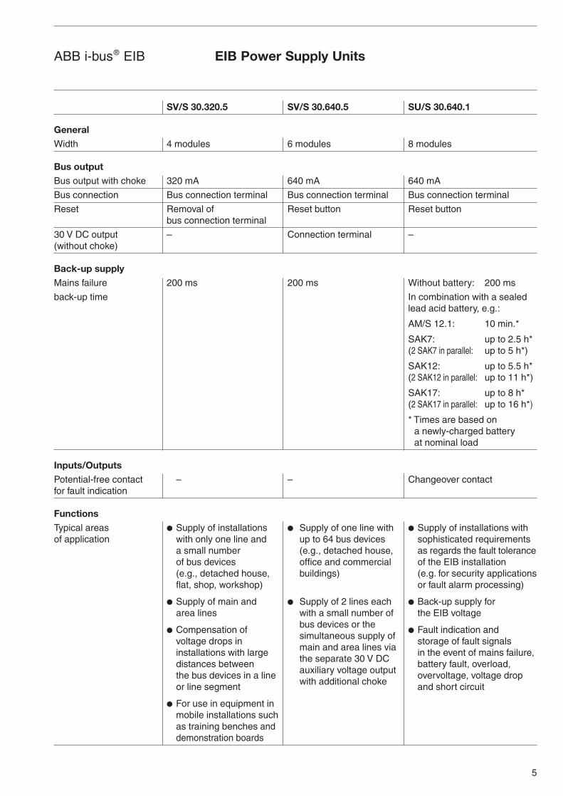
SV/S 30.320.5 SV/S 30.640.5 SU/S 30.640.1
GeneralWidth 4 modules 6 modules 8 modules
Bus outputBus output with choke 320 mA 640 mA 640 mA
Bus connection Bus connection terminal Bus connection terminal Bus connection terminal
Reset Removal of Reset button Reset buttonbus connection terminal
30 V DC output – Connection terminal –(without choke)
Back-up supplyMains failure 200 ms 200 ms Without battery: 200 ms
back-up time In combination with a sealed lead acid battery, e.g.:
AM/S 12.1: 10 min.*
SAK7: up to 2.5 h*(2 SAK7 in parallel: up to 5 h*)
SAK12: up to 5.5 h*(2 SAK12 in parallel: up to 11 h*)
SAK17: up to 8 h*(2 SAK17 in parallel: up to 16 h*)
* Times are based ona newly-charged batteryat nominal load
Inputs/OutputsPotential-free contact – – Changeover contactfor fault indication
FunctionsTypical areas ● Supply of installations ● Supply of one line with ● Supply of installations withof application with only one line and up to 64 bus devices sophisticated requirements
a small number (e.g., detached house, as regards the fault toleranceof bus devices office and commercial of the EIB installation(e.g., detached house, buildings) (e.g. for security applicationsflat, shop, workshop) or fault alarm processing)
● Supply of main and ● Supply of 2 lines each ● Back-up supply forarea lines with a small number of the EIB voltage
● Compensation of bus devices or the ● Fault indication and
voltage drops in simultaneous supply of storage of fault signalsinstallations with large main and area lines via in the event of mains failure,distances between the separate 30 V DC battery fault, overload,the bus devices in a line auxiliary voltage output overvoltage, voltage dropor line segment with additional choke and short circuit
● For use in equipment inmobile installations such as training benches and demonstration boards
6
ABB i-bus® EIB
2 SV/S 30.320.5EIB Power Supply,320 mA, MDRC
2.1 General
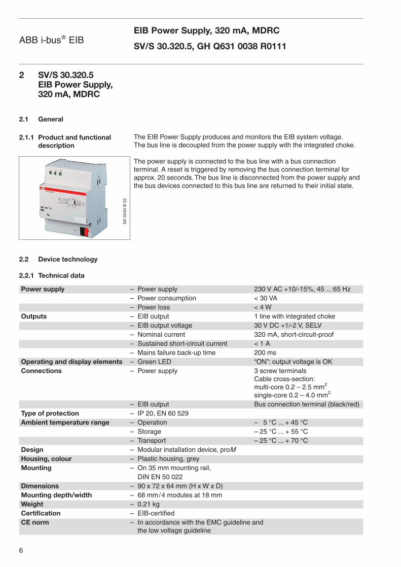
2.1.1 Product and functionaldescription
2.2 Device technology
2.2.1 Technical data
The EIB Power Supply produces and monitors the EIB system voltage.The bus line is decoupled from the power supply with the integrated choke.
The power supply is connected to the bus line with a bus connection terminal. A reset is triggered by removing the bus connection terminal forapprox. 20 seconds. The bus line is disconnected from the power supply andthe bus devices connected to this bus line are returned to their initial state.
Power supply – Power supply 230 V AC +10/-15%, 45 ... 65 Hz– Power consumption < 30 VA– Power loss < 4 W
Outputs – EIB output 1 line with integrated choke– EIB output voltage 30 V DC +1/-2 V, SELV– Nominal current 320 mA, short-circuit-proof– Sustained short-circuit current < 1 A– Mains failure back-up time 200 ms
Operating and display elements – Green LED “ON”: output voltage is OKConnections – Power supply 3 screw terminals
Cable cross-section:multi-core 0.2 – 2.5 mm2
single-core 0.2 – 4.0 mm2
– EIB output Bus connection terminal (black/red)Type of protection – IP 20, EN 60 529Ambient temperature range – Operation – 5 °C ... + 45 °C
– Storage – 25 °C ... + 55 °C– Transport – 25 °C ... + 70 °C
Design – Modular installation device, proMHousing, colour – Plastic housing, greyMounting – On 35 mm mounting rail,
DIN EN 50 022Dimensions – 90 x 72 x 64 mm (H x W x D)Mounting depth/width – 68 mm/4 modules at 18 mmWeight – 0.21 kgCertification – EIB-certifiedCE norm – In accordance with the EMC guideline and
the low voltage guideline
EIB Power Supply, 320 mA, MDRC
SV/S 30.320.5, GH Q631 0038 R0111
SK
00
40
B 0
2
7
ABB i-bus® EIB
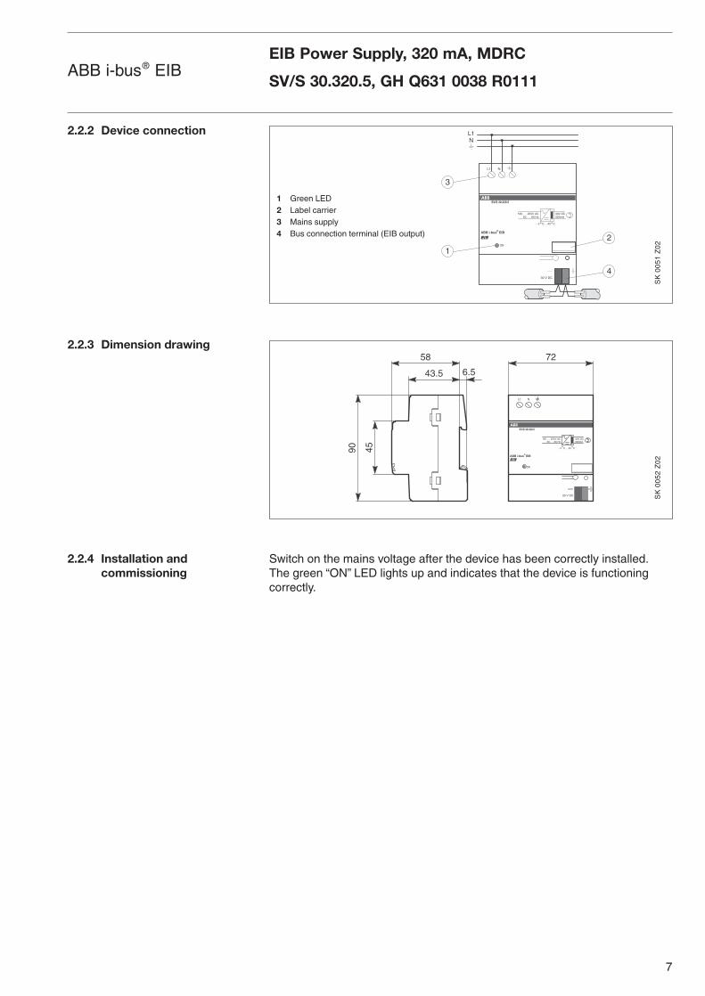
2.2.2 Device connection
2.2.3 Dimension drawing
2.2.4 Installation and commissioning
EIB Power Supply, 320 mA, MDRC
SV/S 30.320.5, GH Q631 0038 R0111
Switch on the mains voltage after the device has been correctly installed.The green “ON” LED lights up and indicates that the device is functioningcorrectly.
ABB i-bus® EIB
SV/S 30.320.5
30V DC320mA
195 . . . 255V AC
- 5 C. . .45 C
30 V DC
50 . . . 60 Hz
ON
L1 N
L1N
2
3
1
4
SK
00
51
Z0
2
1 Green LED2 Label carrier3 Mains supply4 Bus connection terminal (EIB output)
ABB i-bus® EIB
SV/S 30.320.5
30V DC320mA
195 . . . 255V AC
- 5 C. . .45 C
30 V DC
50 . . . 60 Hz
ON
L1 N
4558
43.5 6.5
9072
SK
00
52
Z0
2
8
ABB i-bus® EIB
The EIB Power Supply SV/S 30.320.5 is particularly suitable for the supply of:
– lines with a small number of devices
– small EIB installations with only one line, e.g., detached houses, flats,shops, workshops
– main lines and area lines
– installations with large distances between the bus devices of a line or linesegment to compensate for the voltage drop
– mobile installations, e.g., training benches, demonstration boards
To carry out a reset, remove the bus connection terminal for approx. 20 se-conds from the EIB power supply.
During normal operation, the green “ON” LED lights up. If it does not light up,a fault is present. Check whether the connected EIB line has experienced ashort circuit and whether the mains voltage is OK. If the green “ON” LED stilldoes not light up, the number of bus devices connected to the EIB line shouldbe reduced until an overload is no longer present and the green “ON” LEDlights up.
Once the fault has been rectified, carry out a reset by removing the busconnection terminal for approx. 20 seconds.
2.3 Planning and application
2.3.1 Device application
2.4 Function and operation
2.4.1 Reset
2.4.2 Fault
EIB Power Supply, 320 mA, MDRC
SV/S 30.320.5, GH Q631 0038 R0111

9
ABB i-bus® EIBEIB Power Supply, 320 mA, MDRC
SV/S 30.320.5, GH Q631 0038 R0111
10
ABB i-bus® EIB
3 SV/S 30.640.5 EIB Power Supply,640 mA, MDRC
3.1 General
3.1.1 Product and functionaldescription
3.2 Device technology
3.2.1 Technical data
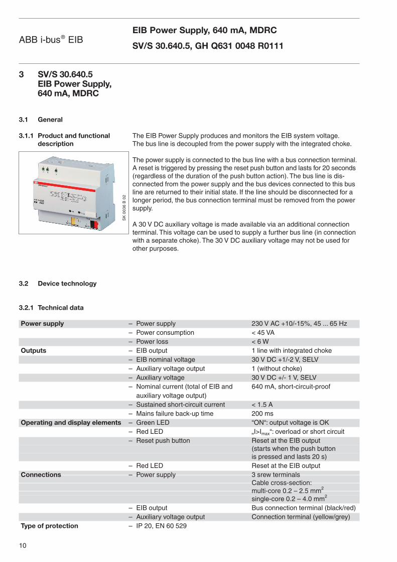
The EIB Power Supply produces and monitors the EIB system voltage.The bus line is decoupled from the power supply with the integrated choke.
The power supply is connected to the bus line with a bus connection terminal.A reset is triggered by pressing the reset push button and lasts for 20 seconds(regardless of the duration of the push button action). The bus line is dis-connected from the power supply and the bus devices connected to this busline are returned to their initial state. If the line should be disconnected for alonger period, the bus connection terminal must be removed from the powersupply.
A 30 V DC auxiliary voltage is made available via an additional connectionterminal. This voltage can be used to supply a further bus line (in connectionwith a separate choke). The 30 V DC auxiliary voltage may not be used forother purposes.
EIB Power Supply, 640 mA, MDRC
SV/S 30.640.5, GH Q631 0048 R0111
Power supply – Power supply 230 V AC +10/-15%, 45 ... 65 Hz– Power consumption < 45 VA– Power loss < 6 W
Outputs – EIB output 1 line with integrated choke– EIB nominal voltage 30 V DC +1/-2 V, SELV– Auxiliary voltage output 1 (without choke)– Auxiliary voltage 30 V DC +/- 1 V, SELV– Nominal current (total of EIB and 640 mA, short-circuit-proof
auxiliary voltage output)– Sustained short-circuit current < 1.5 A– Mains failure back-up time 200 ms
Operating and display elements – Green LED “ON“: output voltage is OK– Red LED „I>Imax“: overload or short circuit– Reset push button Reset at the EIB output
(starts when the push button is pressed and lasts 20 s)
– Red LED Reset at the EIB outputConnections – Power supply 3 srew terminals
Cable cross-section:multi-core 0.2 – 2.5 mm2
single-core 0.2 – 4.0 mm2
– EIB output Bus connection terminal (black/red)– Auxiliary voltage output Connection terminal (yellow/grey)
Type of protection – IP 20, EN 60 529
SK
00
36
B 0
2
11
ABB i-bus® EIB
3.2.2 Device connection
3.2.3 Dimension drawing
3.2.4 Installation andcommissioning
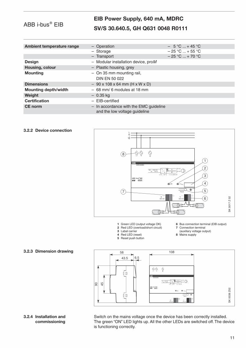
1 Green LED (output voltage OK) 6 Bus connection terminal (EIB output)2 Red LED (overload/short circuit) 7 Connection terminal3 Label carrier (auxiliary voltage output)4 Red LED (reset) 8 Mains supply5 Reset push button
Switch on the mains voltage once the device has been correctly installed.The green “ON” LED lights up. All the other LEDs are switched off. The deviceis functioning correctly.
EIB Power Supply, 640 mA, MDRC
SV/S 30.640.5, GH Q631 0048 R0111
Ambient temperature range – Operation – 5 °C ... + 45 °C– Storage – 25 °C ... + 55 °C– Transport – 25 °C ... + 70 °C
Design – Modular installation device, proMHousing, colour – Plastic housing, greyMounting – On 35 mm mounting rail,
DIN EN 50 022Dimensions – 90 x 108 x 64 mm (H x W x D)Mounting depth/width – 68 mm/ 6 modules at 18 mmWeight – 0.35 kgCertification – EIB-certifiedCE norm – In accordance with the EMC guideline
and the low voltage guideline
ABB i-bus® EIBR
LN
L1 N
2 31
SV/S 30.640.5
30V DC195 . . . 255V AC
- 5 C. . .45 C
50 . . . 60 HzI130V DCI2
1
2I1 I2+ 640 mA<_
ON I >Imax
30V DC1
30V DC2
Reset
6
2
1
3
4
5
8
7
SK
00
17
Z 0
2
ABB i-bus® EIBR
L1 N
2 31
SV/S 30.640.5
30V DC195 . . . 255V AC
- 5 C. . .45 C
50 . . . 60 HzI130V DCI2
1
2
I1 I2+ 640 mA<_
ON I >Imax
30V DC1
30V DC2
Reset
108
45
58
43.5 6.5
90
SK
00
38
Z0
2
12
3.3 Planning and application
3.3.1 Device application
3.3.2 Application example
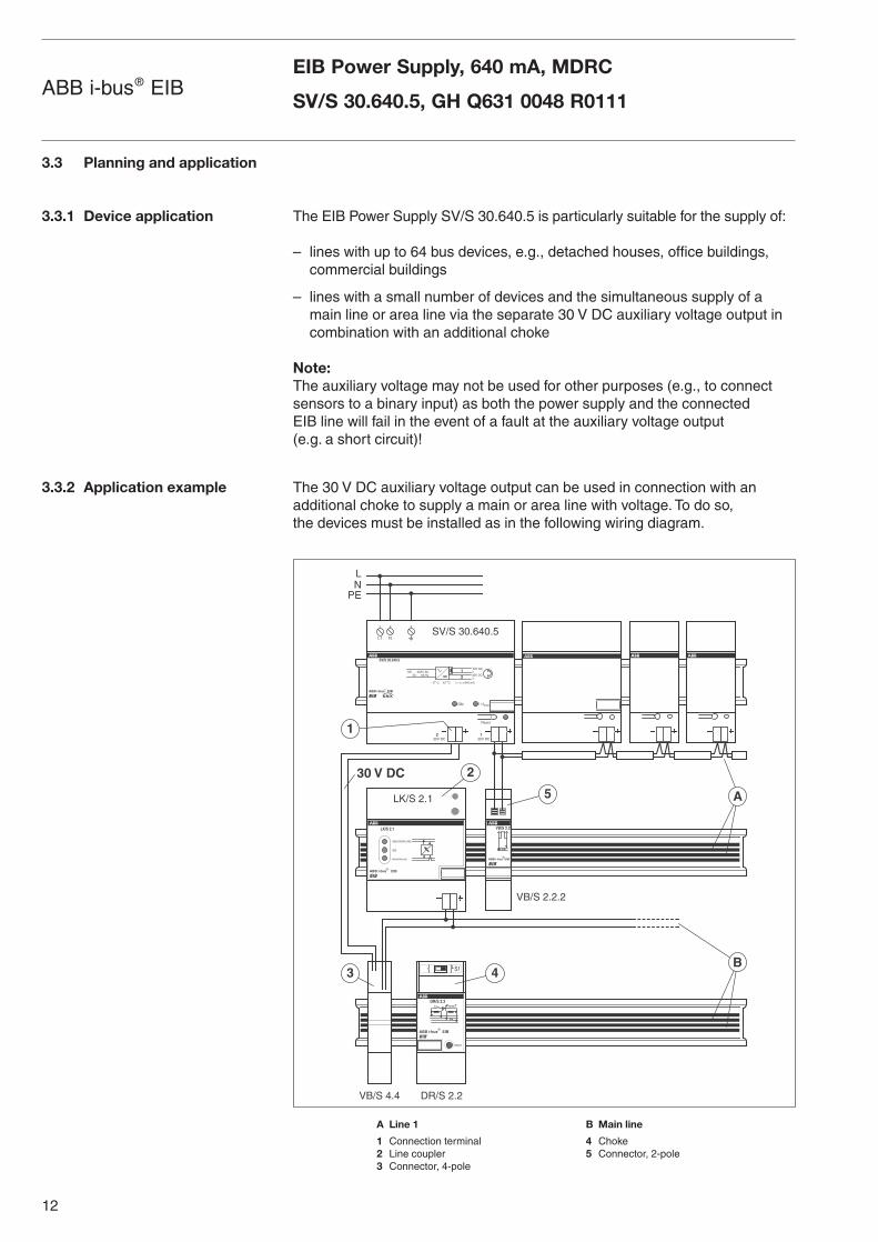
The EIB Power Supply SV/S 30.640.5 is particularly suitable for the supply of:
– lines with up to 64 bus devices, e.g., detached houses, office buildings, commercial buildings
– lines with a small number of devices and the simultaneous supply of amain line or area line via the separate 30 V DC auxiliary voltage output incombination with an additional choke
Note:The auxiliary voltage may not be used for other purposes (e.g., to connectsensors to a binary input) as both the power supply and the connected EIB line will fail in the event of a fault at the auxiliary voltage output (e.g. a short circuit)!
The 30 V DC auxiliary voltage output can be used in connection with anadditional choke to supply a main or area line with voltage. To do so, the devices must be installed as in the following wiring diagram.
A Line 1 B Main line
1 Connection terminal 4 Choke2 Line coupler 5 Connector, 2-pole3 Connector, 4-pole
EIB Power Supply, 640 mA, MDRC
SV/S 30.640.5, GH Q631 0048 R0111ABB i-bus® EIB
ABB i-bus EIB
EIB
VB/S 2.2
LN
L1 N
2 31
ABB i-bus EIB
SV/S 30.640.5
30V DC195 . . . 255V AC
- 5 C. . .45 C
50 . . . 60 HzI130V DCI2
12
I1 I2+ 640 mA<_
ON I >Imax
30V DC1
30V DC2
Reset
ABB i-bus®
EIB
LK/S 2.1
SEKUNDÄRLINIE
ON
PRIMÄRLINIE
DR/S 2.2
EIB
S1
RESET
RESET
S1
ABB i-bus®
EIB
SV/S 30.640.5
LK/S 2.1
VB/S 2.2.2
VB/S 4.4 DR/S 2.2
PE
1
2
3 4
5
30 V DC
A
B
R
®
®
13
3.4 Function and operation
3.4.1 Reset
3.4.2 Fault
To carry out a reset, press the reset push button. The red “Reset” LED lightsup. The reset lasts approx. 20 seconds, regardless of the duration of the pushbutton action. The bus line is disconnected from the power supply and thebus devices connected to the bus line are returned to their initial state.The “Reset” LED extinguishs when the reset has finished.
If the line should be disconnected for a longer period, remove the busconnection terminal from the EIB power supply.
During normal operation, the green “ON” LED lights up.
If only the red LED “I>Imax” lights up, the EIB output has experienced anoverload or short circuit. Rectify the short circuit or reduce the number of busdevices if necessary until an overload is no longer present and only the green“ON” LED lights up.
If the green “ON” LED and the red LED “I>Imax” light up simultaneously, thebus line has experienced an overload and the correct function cannot beguaranteed. Reduce the number of bus devices until the overload is no longer present and only the green “ON” LED lights up.
If neither LED lights up, the mains voltage is disconnected. Connect thevoltage to the system and carry out a reset.
Once the fault has been rectified, carry out a reset by pressing the reset pushbutton.
EIB Power Supply, 640 mA, MDRC
SV/S 30.640.5, GH Q631 0048 R0111ABB i-bus® EIB
14
4 SU/S 30.640.1UninterruptibleEIB Power Supply,640 mA, MDRC
4.1 General
4.1.1 Product and functionaldescription
4.2 Device technology
4.2.1 Technical data
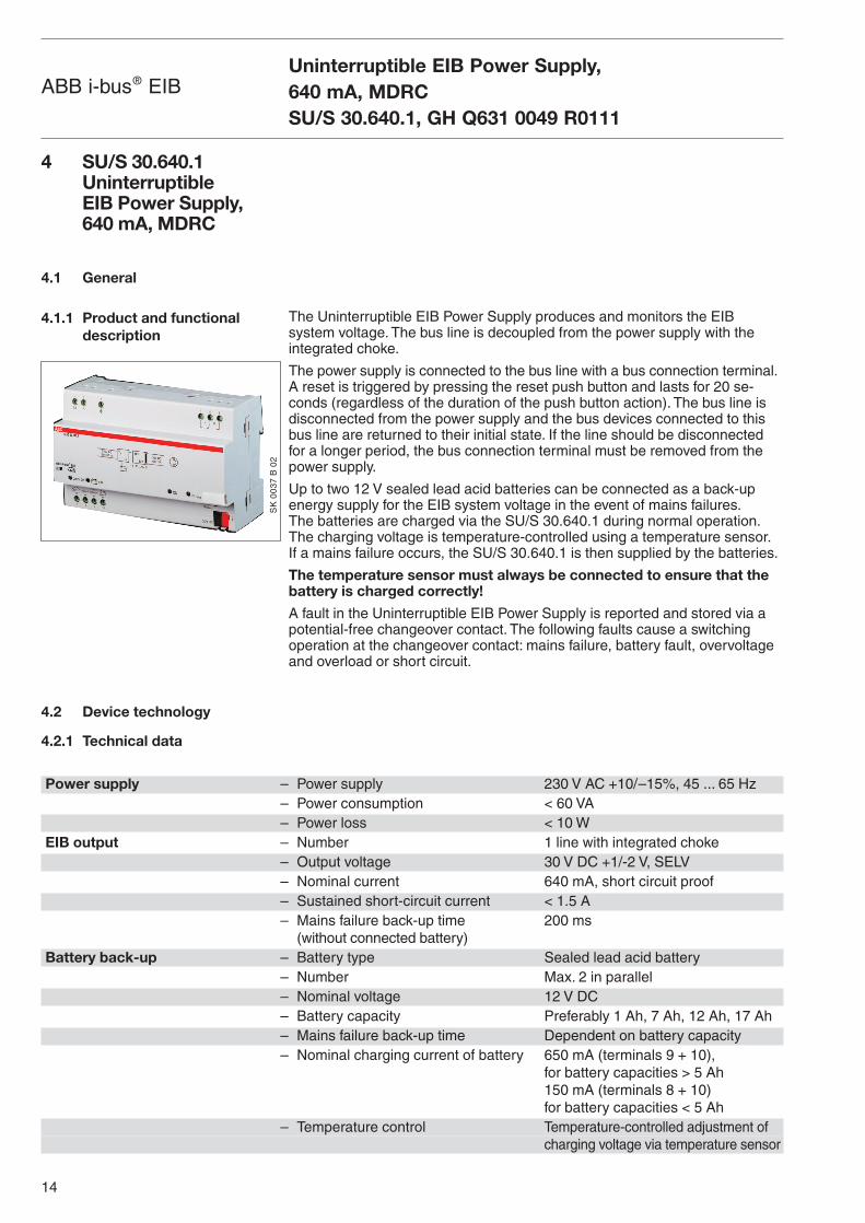
The Uninterruptible EIB Power Supply produces and monitors the EIB system voltage. The bus line is decoupled from the power supply with theintegrated choke.
The power supply is connected to the bus line with a bus connection terminal.A reset is triggered by pressing the reset push button and lasts for 20 se-conds (regardless of the duration of the push button action). The bus line isdisconnected from the power supply and the bus devices connected to thisbus line are returned to their initial state. If the line should be disconnectedfor a longer period, the bus connection terminal must be removed from thepower supply.
Up to two 12 V sealed lead acid batteries can be connected as a back-upenergy supply for the EIB system voltage in the event of mains failures.The batteries are charged via the SU/S 30.640.1 during normal operation.The charging voltage is temperature-controlled using a temperature sensor.If a mains failure occurs, the SU/S 30.640.1 is then supplied by the batteries.
The temperature sensor must always be connected to ensure that thebattery is charged correctly!
A fault in the Uninterruptible EIB Power Supply is reported and stored via apotential-free changeover contact. The following faults cause a switchingoperation at the changeover contact: mains failure, battery fault, overvoltageand overload or short circuit.
Uninterruptible EIB Power Supply, 640 mA, MDRCSU/S 30.640.1, GH Q631 0049 R0111
ABB i-bus® EIB
Power supply – Power supply 230 V AC +10/–15%, 45 ... 65 Hz– Power consumption < 60 VA– Power loss < 10 W
EIB output – Number 1 line with integrated choke– Output voltage 30 V DC +1/-2 V, SELV– Nominal current 640 mA, short circuit proof– Sustained short-circuit current < 1.5 A– Mains failure back-up time 200 ms
(without connected battery)Battery back-up – Battery type Sealed lead acid battery
– Number Max. 2 in parallel– Nominal voltage 12 V DC– Battery capacity Preferably 1 Ah, 7 Ah, 12 Ah, 17 Ah– Mains failure back-up time Dependent on battery capacity– Nominal charging current of battery 650 mA (terminals 9 + 10),
for battery capacities > 5 Ah150 mA (terminals 8 + 10)for battery capacities < 5 Ah
– Temperature control Temperature-controlled adjustment ofcharging voltage via temperature sensor
SK
00
37
B 0
2
15
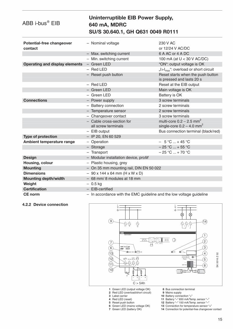
4.2.2 Device connection
1 Green LED (output voltage OK) 8 Bus connection terminal2 Red LED (overload/short circuit) 9 Mains supply3 Label carrier 10 Battery connection “+”4 Red LED (reset) 11 Battery “–” 650 mA/Temp. sensor “–”5 Reset push button 12 Battery “–” 150 mA/Temp. sensor “–”6 Green LED (mains voltage OK) 13 Connection for temperature sensor “+”7 Green LED (battery OK) 14 Connection for potential-free changeover contact
Uninterruptible EIB Power Supply, 640 mA, MDRCSU/S 30.640.1, GH Q631 0049 R0111
ABB i-bus® EIB
ABB i-bus® EIBR
87 109 30V DC
Reset
5 6
µ
4
µL1 N
2 31
�
LN
LN
OK
9
6
7
13
12
4
8
2
5
1
3
14
SU/S 30.640.1
30V DC230V AC
- 5 C. . .45 C
50 / 60 Hz
230V OK
12V
30V640 mA
ON I > ImaxOK
11
10
C > 5Ah
12V
�
Code /650 mA150 mA
SK
00
16
Z 0
2
Potential-free changeover – Nominal voltage 230 V AC contact or 12/24 V AC/DC
– Max. switching current 6 A AC or 4 A DC– Min. switching current 100 mA (at U < 30 V AC/DC)
Operating and display elements – Green LED “ON“: output voltage is OK– Red LED „I>Imax“: overload or short circuit– Reset push button Reset starts when the push button
is pressed and lasts 20 s– Red LED Reset at the EIB output– Green LED Main voltage is OK– Green LED Battery is OK
Connections – Power supply 3 screw terminals– Battery connection 2 screw terminals– Temperature sensor 2 screw terminals– Changeover contact 3 screw terminals– Cable cross-section for multi-core 0.2 – 2.5 mm2
all screw terminals single-core 0.2 – 4.0 mm2
– EIB output Bus connection terminal (black/red)Type of protection – IP 20, EN 60 529Ambient temperature range – Operation – 5 °C ... + 45 °C
– Storage – 25 °C ... + 55 °C– Transport – 25 °C ... + 70 °C
Design – Modular installation device, proMHousing, colour – Plastic housing, greyMounting – On 35 mm mounting rail, DIN EN 50 022Dimensions – 90 x 144 x 64 mm (H x W x D)Mounting depth/width – 68 mm/ 8 modules at 18 mmWeight – 0.5 kgCertification – EIB-certifiedCE norm – In accordance with the EMC guideline and the low voltage guideline
16
ABB i-bus® EIB
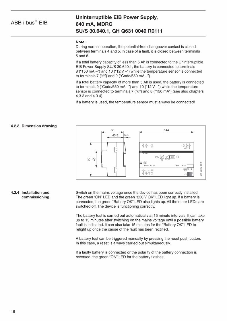
Note:During normal operation, the potential-free changeover contact is closedbetween terminals 4 and 5. In case of a fault, it is closed between terminals 5 and 6.
If a total battery capacity of less than 5 Ah is connected to the Uninterruptible EIB Power Supply SU/S 30.640.1, the battery is connected to terminals 8 (“150 mA –”) and 10 (“12 V +”) while the temperature sensor is connectedto terminals 7 (“ϑ”) and 9 (“Code/650 mA –”).
If a total battery capacity of more than 5 Ah is used, the battery is connectedto terminals 9 (“Code/650 mA –”) and 10 (“12 V +”) while the temperaturesensor is connected to terminals 7 (“ϑ”) and 8 (“150 mA”) (see also chapters4.3.3 and 4.3.4).
If a battery is used, the temperature sensor must always be connected!
Switch on the mains voltage once the device has been correctly installed.The green “ON” LED and the green “230 V OK” LED light up. If a battery isconnected, the green “Battery OK” LED also lights up. All the other LEDs areswitched off. The device is functioning correctly.
The battery test is carried out automatically at 15 minute intervals. It can takeup to 15 minutes after switching on the mains voltage until a possible batteryfault is indicated. It can also take 15 minutes for the “Battery OK” LED torelight up once the cause of the fault has been rectified.
A battery test can be triggered manually by pressing the reset push button.In this case, a reset is always carried out simultaneously.
If a faulty battery is connected or the polarity of the battery connection isreversed, the green “ON” LED for the battery flashes.
4.2.3 Dimension drawing
4.2.4 Installation and commissioning
Uninterruptible EIB Power Supply, 640 mA, MDRCSU/S 30.640.1, GH Q631 0049 R0111
45
58
43.5 6.5
90
ABB i-bus® EIBR
87 109 30V DC
Reset
5 6
µ
4
µL1 N
2 31
OKSU/S 30.640.1
30V DC230V AC
- 5 C. . .45 C
50 / 60 Hz
230V OK
12V
30V640 mA
ON I > ImaxOK
Code /650 mA150 mA
12V
144
�
SK
00
36
Z0
2
17
ABB i-bus® EIB
4.3 Planning and application
4.3.1 Device application
4.3.2 Back-up supply
The Uninterruptible EIB Power Supply SU/S 30.640.1 is particularly suitablefor the supply of:– installations with sophisticated requirements as regards the functional reli-
ability of the EIB installation (e.g., for security applications or fault monitoring)
– installations requiring a back-up supply for the EIB voltage for up to 16 hours
– installations with fault reporting and storage of fault signals in the event ofmains failure, battery fault, overload, short circuit, overvoltage and voltagedrop
The SU/S 30.640.1 can buffer the connected EIB line for at least 200 mswithout a connected battery in the event of a mains failure.
To bridge longer periods of mains failure, the SU/S 30.640.1 can be providedwith a back-up supply using a 12 V DC battery. The mains failure back-up timeis dependent on the load connected to the EIB line and the battery capacity.
ABB offers four different batteries with various capacity. The battery moduleAM/S 12.1 is a DIN rail mounted device, while the sealed lead acid batteriesSAK7, SAK12 and SAK17 can be installed in a separate, universal distributionboard.
When the Uninterruptible EIB Power Supply SU/S 30.640.1 is used at fullcapacity (64 bus devices), the sealed lead acid batteries buffer the EIB system voltage for the following mains failure back-up times:
Battery Module, 12 V DC, MDRC, AM/S 12.1Battery capacity: 1 AhMains failure back-up time: 10 min.*
Sealed Lead Acid Battery, SAK7Battery capacity: 7 AhMains failure back-up time: up to 2.5 h* (1 x SAK7)
up to 5 h* (2 x SAK7 in parallel)
Sealed Lead Acid Battery, SAK12Battery capacity: 12 AhMains failure back-up time: up to 5.5 h* (1 x SAK12)
up to 11 h* (2 x SAK12 in parallel)
Sealed Lead Acid Battery, SAK17Battery capacity: 17 AhMains failure back-up time: up to 8 h* (1 x SAK17)
up to 16 h* (2 x SAK17 in parallel)* The periods are based on a newly-charged batteries at full capacity utilisation of the
Uninterruptible EIB Power Supply SU/S 30.640.1
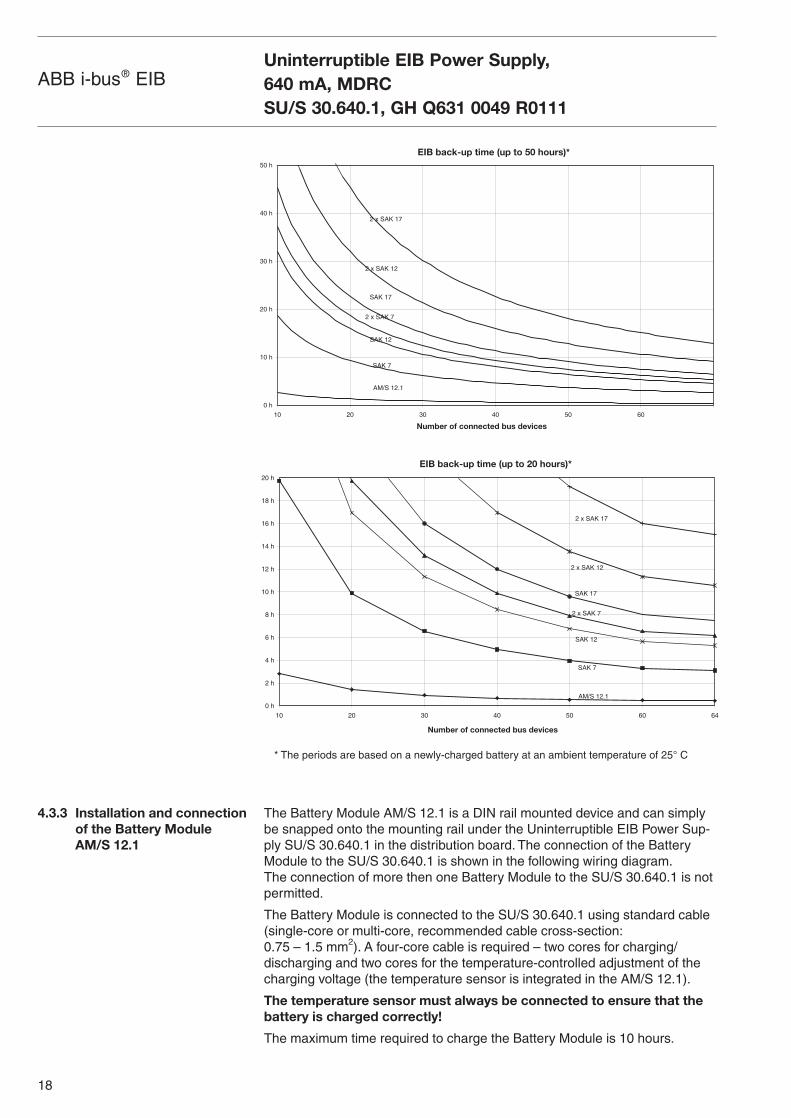
The minimum back-up times are displayed in the following diagrams depen-dent on the number of supplied EIB devices. The first diagram shows back-uptimes on a large scale (back-up supply for up to 50 hours). The second diagram shows back-up times on a smaller scale (up to 20 hours).
Uninterruptible EIB Power Supply, 640 mA, MDRCSU/S 30.640.1, GH Q631 0049 R0111
18
ABB i-bus® EIB
The Battery Module AM/S 12.1 is a DIN rail mounted device and can simplybe snapped onto the mounting rail under the Uninterruptible EIB Power Sup-ply SU/S 30.640.1 in the distribution board. The connection of the BatteryModule to the SU/S 30.640.1 is shown in the following wiring diagram.The connection of more then one Battery Module to the SU/S 30.640.1 is notpermitted.
The Battery Module is connected to the SU/S 30.640.1 using standard cable(single-core or multi-core, recommended cable cross-section:0.75 – 1.5 mm2). A four-core cable is required – two cores for charging/discharging and two cores for the temperature-controlled adjustment of thecharging voltage (the temperature sensor is integrated in the AM/S 12.1).
The temperature sensor must always be connected to ensure that thebattery is charged correctly!
The maximum time required to charge the Battery Module is 10 hours.
4.3.3 Installation and connectionof the Battery Module AM/S 12.1
Uninterruptible EIB Power Supply, 640 mA, MDRCSU/S 30.640.1, GH Q631 0049 R0111
EIB back-up time (up to 50 hours)*
0 h
10 h
20 h
30 h
40 h
50 h
10 20 30 40 50 60
AM/S 12.1
SAK 7
SAK 12
2 x SAK 7
SAK 17
2 x SAK 12
2 x SAK 17
Number of connected bus devices
* The periods are based on a newly-charged battery at an ambient temperature of 25° C
EIB back-up time (up to 20 hours)*
0 h
2 h
4 h
6 h
8 h
10 h
12 h
14 h
16 h
18 h
20 h
10 20 30 40 50 60 64
Number of connected bus devices
AM/S 12.1
SAK 7
SAK 12
2 x SAK 7
SAK 17
2 x SAK 12
2 x SAK 17
19
ABB i-bus® EIB
4.3.4 Installation and connectionof the sealed lead acid batteries SAK7, SAK12,SAK17
4.3.5 Connection of the potential-free changeover contact
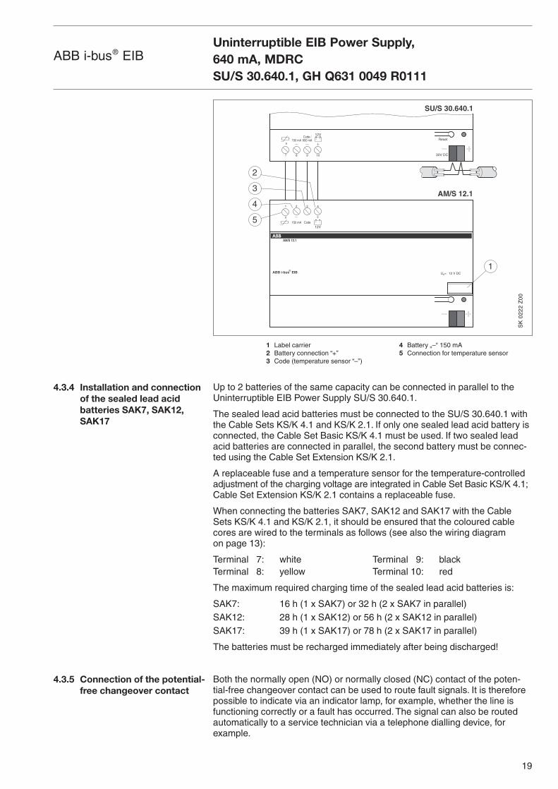
1 Label carrier 4 Battery „–“ 150 mA2 Battery connection “+” 5 Connection for temperature sensor3 Code (temperature sensor “–”)
Up to 2 batteries of the same capacity can be connected in parallel to theUninterruptible EIB Power Supply SU/S 30.640.1.
The sealed lead acid batteries must be connected to the SU/S 30.640.1 withthe Cable Sets KS/K 4.1 and KS/K 2.1. If only one sealed lead acid battery isconnected, the Cable Set Basic KS/K 4.1 must be used. If two sealed leadacid batteries are connected in parallel, the second battery must be connec-ted using the Cable Set Extension KS/K 2.1.
A replaceable fuse and a temperature sensor for the temperature-controlledadjustment of the charging voltage are integrated in Cable Set Basic KS/K 4.1;Cable Set Extension KS/K 2.1 contains a replaceable fuse.
When connecting the batteries SAK7, SAK12 and SAK17 with the CableSets KS/K 4.1 and KS/K 2.1, it should be ensured that the coloured cablecores are wired to the terminals as follows (see also the wiring diagram on page 13):
Terminal 7: white Terminal 9: blackTerminal 8: yellow Terminal 10: red
The maximum required charging time of the sealed lead acid batteries is:
SAK7: 16 h (1 x SAK7) or 32 h (2 x SAK7 in parallel)SAK12: 28 h (1 x SAK12) or 56 h (2 x SAK12 in parallel)SAK17: 39 h (1 x SAK17) or 78 h (2 x SAK17 in parallel)
The batteries must be recharged immediately after being discharged!
Both the normally open (NO) or normally closed (NC) contact of the poten-tial-free changeover contact can be used to route fault signals. It is thereforepossible to indicate via an indicator lamp, for example, whether the line isfunctioning correctly or a fault has occurred. The signal can also be routedautomatically to a service technician via a telephone dialling device, for example.
Uninterruptible EIB Power Supply, 640 mA, MDRCSU/S 30.640.1, GH Q631 0049 R0111
2 41 3
12VCode150 mA
ABB i-bus EIB
AM/S 12.1 OK
SU/S 30.640.1
AM/S 12.1
1
2
Un= 12 V DC
12V
87 109 30V DC
ResetCode /650 mA150 mA
3
4
5
®
�
�
SK
02
22
Z0
0
20
ABB i-bus® EIB
Press the reset pushbutton to carry out a reset.The red “Reset” LED lights up.The reset lasts approx. 20 seconds, regardless of the duration of the pushbutton action. The bus line is disconnected from the power supply and thebus devices connected to the bus line are returned to their initial state.The “Reset” LED is extinguished when the reset has finished.
Due to the service life of the batteries, they should be replaced approx. everyfour years to guarantee the minimum specified mains failure back-up time.
The Uninterruptible EIB Power Supply permanently monitors the bus line, themains power supply and the battery voltage. The green “ON” LED is extin-guished when a fault occurs. The cause of the fault is indicated by the LEDsdirectly on the device and routed via the potential-free changeover contact.
In the event of an overload or overvoltage at the EIB output, the fault signal isstored, i.e., the potential-free changeover contact and the corresponding LEDremain in the fault state, even if the cause for the fault signal is no longerpresent and the EIB line is again supplied with voltage. In this case, theinstallation will continue to function correctly but a service technician musteliminate the problem as otherwise faults may continue to occur in the future.
If the fault is rectified, the stored alarm can be acknowledged and deleted bypressing the reset pushbutton once. The potential-free contact returns to thenormal position and the LED lights for normal operation. A bus reset is car-ried out when the reset push button is pressed a second time.
If the fault is not rectified, pressing the reset push button will indeed carry outa bus reset, however the fault remains stored and the potential-free change-over contact and the LED remain in the fault state.
Monitoring the bus line
Overload/short circuit: In the event of an overload of the bus line, the redLED “I>Imax” lights up. If the overload generates bus currents of more than 1.2 A (e.g. during a short circuit), the output voltage is automatically limitedand the green “ON” LED is extinguished. A transient overload generally doesnot lead to problems in the installation. If the bus line experiences an overlo-ad or short circuit for longer than 10 seconds, the potential-free changeovercontact also switches to the fault state. The fault signal is stored.
Overvoltage: If an overvoltage occurs on the bus line, the red LED “I>Imax”starts to flash. The potential-free changeover contact goes into the fault state.The Uninterruptible EIB Power Supply automatically carrys out a bus reset.The red “Reset” LED lights up during the reset. The fault signal is stored.
If an overload and overvoltage occur simultaneously, the signal for overvolta-ge has higher priority, i.e., the LED “I>Imax” flashes and a bus reset is carriedout automatically. The fault signal is stored.
4.4 Function and operation
4.4.1 Reset
4.4.2 Battery life span
4.4.3 Fault
Uninterruptible EIB Power Supply, 640 mA, MDRCSU/S 30.640.1, GH Q631 0049 R0111
21
ABB i-bus® EIB
Monitoring the power supply
During a mains failure, the bus line is supplied by the connected battery, i.e.,no faults occur in the installation. If the mains voltage fails, the potential-freechangeover contact switches to the fault state and the LED “230 V AC OK”extinguishes. If the mains voltage recovers, the potential-free changeovercontact reverts to the normal position and the LED lights up green. The faultsignal is not stored.
Monitoring the battery voltage
A battery test is carried out automatically at 15 minute intervals. It is alsopossible to manually trigger a battery test by pressing the reset push button.If a battery fault is present, the potential-free changeover contact switches tothe fault state and the “Battery OK” LED for the battery is extinguished.If the polarity of the battery connection is reversed, the “Battery OK” LEDflashes. Once the cause of the fault is rectified, the potential-free changeovercontact reverts to the normal position and the LED lights up green. The faultsignal is not stored.
If no batteries are connected, the “OK” LED for the battery does not light.
Note:It can take up to 15 minutes after the connection of the mains supply before apossible battery fault is indicated. Once the fault has been rectified, it canalso take 15 minutes for the potential-free changeover contact to revert to thenormal position and the LED to extinguish.
Uninterruptible EIB Power Supply, 640 mA, MDRCSU/S 30.640.1, GH Q631 0049 R0111
22
ABB i-bus® EIB
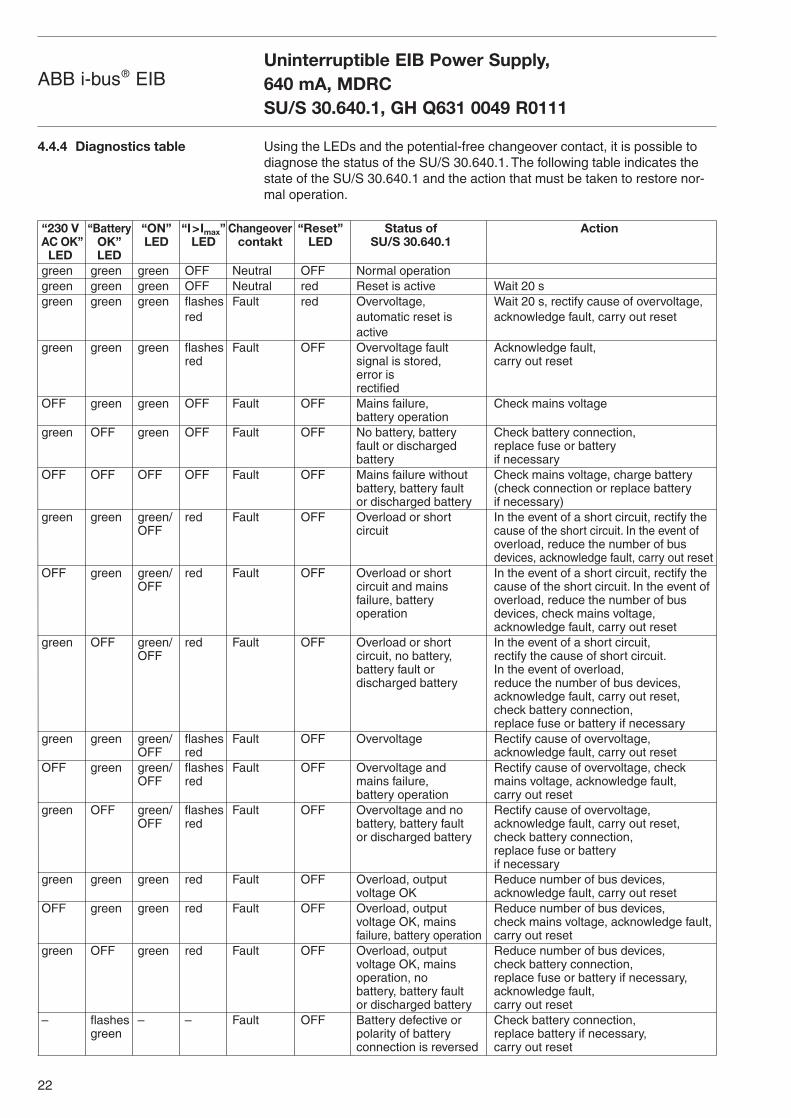
Using the LEDs and the potential-free changeover contact, it is possible todiagnose the status of the SU/S 30.640.1. The following table indicates thestate of the SU/S 30.640.1 and the action that must be taken to restore nor-mal operation.
4.4.4 Diagnostics table
Uninterruptible EIB Power Supply, 640 mA, MDRCSU/S 30.640.1, GH Q631 0049 R0111
“230 V “Battery “ON” “I>Imax” Changeover “Reset” Status of ActionAC OK” OK” LED LED contakt LED SU/S 30.640.1LED LED
green green green OFF Neutral OFF Normal operationgreen green green OFF Neutral red Reset is active Wait 20 sgreen green green flashes Fault red Overvoltage, Wait 20 s, rectify cause of overvoltage,
red automatic reset is acknowledge fault, carry out resetactive
green green green flashes Fault OFF Overvoltage fault Acknowledge fault, red signal is stored, carry out reset
error isrectified
OFF green green OFF Fault OFF Mains failure, Check mains voltagebattery operation
green OFF green OFF Fault OFF No battery, battery Check battery connection, fault or discharged replace fuse or battery battery if necessary
OFF OFF OFF OFF Fault OFF Mains failure without Check mains voltage, charge battery battery, battery fault (check connection or replace batteryor discharged battery if necessary)
green green green/ red Fault OFF Overload or short In the event of a short circuit, rectify the OFF circuit cause of the short circuit. In the event of
overload, reduce the number of busdevices, acknowledge fault, carry out reset
OFF green green/ red Fault OFF Overload or short In the event of a short circuit, rectify theOFF circuit and mains cause of the short circuit. In the event of
failure, battery overload, reduce the number of bus operation devices, check mains voltage,
acknowledge fault, carry out resetgreen OFF green/ red Fault OFF Overload or short In the event of a short circuit,
OFF circuit, no battery, rectify the cause of short circuit.battery fault or In the event of overload, discharged battery reduce the number of bus devices,
acknowledge fault, carry out reset, check battery connection,replace fuse or battery if necessary
green green green/ flashes Fault OFF Overvoltage Rectify cause of overvoltage, OFF red acknowledge fault, carry out reset
OFF green green/ flashes Fault OFF Overvoltage and Rectify cause of overvoltage, check OFF red mains failure, mains voltage, acknowledge fault,
battery operation carry out resetgreen OFF green/ flashes Fault OFF Overvoltage and no Rectify cause of overvoltage,
OFF red battery, battery fault acknowledge fault, carry out reset, or discharged battery check battery connection,
replace fuse or battery if necessary
green green green red Fault OFF Overload, output Reduce number of bus devices, voltage OK acknowledge fault, carry out reset
OFF green green red Fault OFF Overload, output Reduce number of bus devices, voltage OK, mains check mains voltage, acknowledge fault, failure, battery operation carry out reset
green OFF green red Fault OFF Overload, output Reduce number of bus devices, voltage OK, mains check battery connection,operation, no replace fuse or battery if necessary, battery, battery fault acknowledge fault, or discharged battery carry out reset
– flashes – – Fault OFF Battery defective or Check battery connection, green polarity of battery replace battery if necessary,
connection is reversed carry out reset
23
ABB i-bus® EIBUninterruptible EIB Power Supply, 640 mA, MDRCSU/S 30.640.1, GH Q631 0049 R0111

24
ABB i-bus® EIBBattery Module, 12 V DC, MDRC
AM/S 12.1, GH Q631 0062 R0111
5 AM/S 12.1Battery Module, 12 V DC, MDRC
5.1 General
5.1.1 Product description
5.2 Device technology
5.2.1 Technical data
The Battery Module is a sealed lead acid battery which acts as a back-upenergy source for the ABB i-bus® EIB system voltage during mains failures.The Battery Module can only be used in combination with the UninterruptibleEIB Power Supply SU/S 30.640.1. The Battery Module is a DIN rail mounteddevice and can simply be snapped onto the mounting rail under the SU/S30.640.1 in the distribution board.
The back-up time is dependent on the bus load, however, a minimum of 10 minutes is guaranted when the EIB line is at capacity (64 bus devices).It is not permitted to connect several Battery Modules in parallel to the SU/S 30.640.1 or to connect the Battery Module in combination with otherbatteries.A temperature sensor for a temperature-controlled adjustment of the char-ging voltage is integrated in the battery module. An integrated fuse protectsthe Battery Module from short circuits.
The temperature sensor must always be connected to ensure that thebattery is charged correctly!
Power supply – Power supply May only be connected to the UninterruptibleEIB Power SupplySU/S 30.640.1
– Nominal voltage 12 V DC– Battery capacity 1 Ah– Charging current 150 mA– Charging time max. 10 h– Mains failure back-up time min. 10 minutes (dependent on
bus load; the back-up timecan be reduced due to aging ofthe battery module)
Safety – Temperature sensor Integrated– Fuse Self-healing (integrated)
Operating and display elements – NoneConnections – Power supply 2 screw terminals
– Temperature sensor 2 screw terminalsCable cross-section:multi-core 0.2 – 2.5 mm2
single-core 0.2 – 4.0 mm2
Type of protection – IP 20, EN 60 529Ambient temperature range – Operation + 5 °C ... + 45 °C
– Storage – 25 °C ... + 20 °C– Transport – 25 °C ... + 50 °C
Design – Modular installation device, pro M
SK
00
38
B 0
2
25
ABB i-bus® EIBBattery Module, 12 V DC, MDRC
AM/S 12.1, GH Q631 0062 R0111
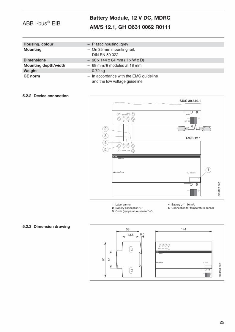
5.2.2 Device connection
5.2.3 Dimension drawing
1 Label carrier 4 Battery „–“ 150 mA2 Battery connection “+” 5 Connection for temperature sensor3 Code (temperature sensor “–”)
Housing, colour – Plastic housing, greyMounting – On 35 mm mounting rail,
DIN EN 50 022Dimensions – 90 x 144 x 64 mm (H x W x D)Mounting depth/width – 68 mm/8 modules at 18 mmWeight – 0.72 kgCE norm – In accordance with the EMC guideline
and the low voltage guideline
2 41 3
12VCode150 mA
ABB i-bus EIB
AM/S 12.1 OK
SU/S 30.640.1
AM/S 12.1
1
2
Un= 12 V DC
12V
87 109 30V DC
ResetCode /650 mA150 mA
3
4
5
®
�
�
45
58
43.5 6.5
90
144
2 41 3
12VCode150 mA
ABB i-bus® EIB
AM/S 12.1 OK
Un= 12 V DC
�
SK
02
22
Z0
2S
K 0
03
4 Z
02
26
ABB i-bus® EIB
The following guidelines should be noted when using the Battery ModuleAM/S 12.1:
1. The Battery Module may only be connected to the Uninterruptible EIBPower Supply SU/S 30.640.1
2. The Battery Module may only be installed on a horizontal mounting rail (35 mm, EN 50 022) in a wall-mounted distribution board.
3. The Battery Module may not be connected in series or in parallel to otherBattery Modules or other sealed lead acid batteries.
4. In the supplied state, the Battery Module is charged or partially charged.The Battery Module must not be stored in a discharged state. If the Battery Module is stored for longer periods without connection to the SU/S 30.640.1, it must be fully charged at least every 6 months. The Battery Module can be stored for max. 2 years at a storage temperature of 20°C.
5. Once the Battery Module has been discharged during normal operation, it must be recharged as soon as possible.
6. Due to the life span of the sealed lead acid battery, it is advisable to replace the Battery Module with a new device approx. every four years.Used Battery Modules can be returned to your EIB representive for disposal.
5.3 Planning and application
5.3.1 Device implementation
Battery Module, 12 V DC, MDRC
AM/S 12.1, GH Q631 0062 R0111

Battery Module, 12 V DC, MDRC
AM/S 12.1, GH Q631 0062 R0111
27
ABB i-bus® EIB

28
6 SAK7, SAK12, SAK17Sealed Lead Acid Batteries
6.1 General
6.1.1 Product and functionaldescription
6.2 Device technology
6.2.1 Technical data for SAK7
N
6.2.2 Technical data for SAK12
6.2.3 Technical data for SAK17
The sealed lead acid batteries SAK7, SAK12 and SAK17 are used to bufferthe EIB system voltage in combination with the Uninterruptible EIB PowerSupply SU/S 30.640.1. A maximum of two sealed lead acid batteries can beconnected in parallel to the SU/S 30.640.1. In this case, two identical sealedlead acid batteries must be used.
When connecting a sealed lead acid battery to the SU/S 30.640.1, the CableSet Basic KS/K 4.1 must be used. When connecting two sealed lead acidbatteries, the Cable Set Basic KS/K 4.1 must be used for the first batterywhile the Cable Set Extension KS/K 2.1 must be used for the second battery.
The service life of the sealed lead acid batteries is 5 years.
Sealed Lead Acid Batteries
SAK7, SAK12, SAK17ABB i-bus® EIB
Nominal voltage – 12 V DCCapacity – 7 AhDimensions – 94 x 151 x 65 (H x W x D)Weight – 2.6 kgService life – 5 yearsAmbient temperature range – Operation – 20 °C ... + 50 °C
– Storage – 20 °C ... + 50 °C– Transport – 20 °C ... + 50 °C
Nominal voltage – 12 V DCCapacity – 12 AhDimensions – 94 x 151 x 98 (H x W x D)Weight – 4.2 kgService life – 5 yearsAmbient temperature range – Operation – 20 °C ... + 50 °C
– Storage – 20 °C ... + 50 °C– Transport – 20 °C ... + 50 °C
Nominal voltage – 12 V DCCapacity – 17 AhDimensions – 167 x 181 x 76 (H x W x D)Weight – 6.8 kgService life – 5 yearsAmbient temperature range – Operation – 20 °C ... + 50 °C
– Storage – 20 °C ... + 50 °C– Transport – 20 °C ... + 50 °C
SK 0252 B 02
29
ABB i-bus® EIB
7 KS/K 4.1 and KS/K 2.1Cable Sets
7.1 General
7.1.1 Product and functionaldescription
7.2 Device technology
7.2.1 Technical data for KS/K 4.1
7.2.2 Technical data for KS/K 2.1
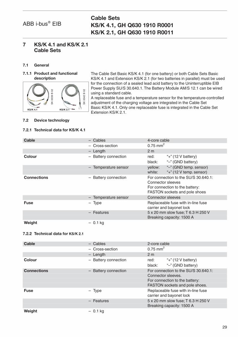
The Cable Set Basic KS/K 4.1 (for one battery) or both Cable Sets BasicKS/K 4.1 and Extension KS/K 2.1 (for two batteries in parallel) must be usedfor the connection of a sealed lead acid battery to the Uninterruptible EIBPower Supply SU/S 30.640.1. The Battery Module AM/S 12.1 can be wiredusing a standard cable.A replaceable fuse and a temperature sensor for the temperature-controlledadjustment of the charging voltage are integrated in the Cable Set Basic KS/K 4.1. Only one replaceable fuse is integrated in the Cable SetExtension KS/K 2.1.
Cable SetsKS/K 4.1, GH Q630 1910 R0001KS/K 2.1, GH Q630 1910 R0011
Cable – Cables 4-core cable– Cross-section 0.75 mm2
– Length 2 mColour – Battery connection red: “+” (12 V battery)
black: “–” (GND battery)– Temperature sensor yellow: “–” (GND temp. sensor)
white: “+” (12 V temp. sensor)Connections – Battery connection For connection to the SU/S 30.640.1:
Connector sleevesFor connection to the battery:FASTON sockets and pole shoes
– Temperature sensor Connector sleevesFuse – Type Replaceable fuse with in-line fuse
carrier and bayonet lock– Features 5 x 20 mm slow fuse; T 6.3 H 250 V
Breaking capacity: 1500 AWeight – 0.1 kg
Cable – Cables 2-core cable– Cross-section 0.75 mm2
– Length 2 mColour – Battery connection red: “+” (12 V battery)
black: “–” (GND battery)Connections – Battery connection For connection to the SU/S 30.640.1:
Connector sleeves.For connection to the battery:FASTON sockets and pole shoes.
Fuse – Type Replaceable fuse with in-line fuse carrier and bayonet lock
– Features 5 x 20 mm slow fuse; T 6.3 H 250 VBreaking capacity: 1500 A
Weight – 0.1 kg
SK
00
39
B 0
2
KS/K 4.1
SK
00
42
B 0
2
KS/K 2.1
30
ABB i-bus® EIB Appendix
8 Appendix
8.1 Ordering information
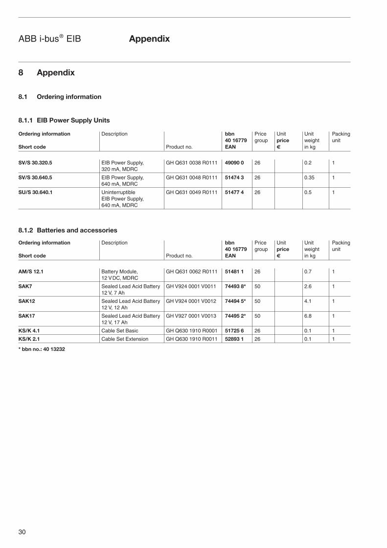
8.1.1 EIB Power Supply Units
8.1.2 Batteries and accessories
SV/S 30.320.5 EIB Power Supply, GH Q631 0038 R0111 49090 0 26 0.2 1320 mA, MDRC
SV/S 30.640.5 EIB Power Supply, GH Q631 0048 R0111 51474 3 26 0.35 1640 mA, MDRC
SU/S 30.640.1 Uninterruptible GH Q631 0049 R0111 51477 4 26 0.5 1EIB Power Supply, 640 mA, MDRC
Ordering information Description bbn Price Unit Unit Packing 40 16779 group price weight unit
Short code Product no. EAN € in kg
AM/S 12.1 Battery Module, GH Q631 0062 R0111 51481 1 26 0.7 112 VDC, MDRC
SAK7 Sealed Lead Acid Battery GH V924 0001 V0011 74493 8* 50 2.6 112 V, 7 Ah
SAK12 Sealed Lead Acid Battery GH V924 0001 V0012 74494 5* 50 4.1 112 V, 12 Ah
SAK17 Sealed Lead Acid Battery GH V927 0001 V0013 74495 2* 50 6.8 112 V, 17 Ah
KS/K 4.1 Cable Set Basic GH Q630 1910 R0001 51725 6 26 0.1 1
KS/K 2.1 Cable Set Extension GH Q630 1910 R0011 52893 1 26 0.1 1
* bbn no.: 40 13232
Ordering information Description bbn Price Unit Unit Packing 40 16779 group price weight unit
Short code Product no. EAN € in kg

The information in this leaflet is subject to change without further notice. Pub
No.
2CD
C 5
01 0
05 D
0201
Your EIB-Partner