Embed Size (px)
Citation preview
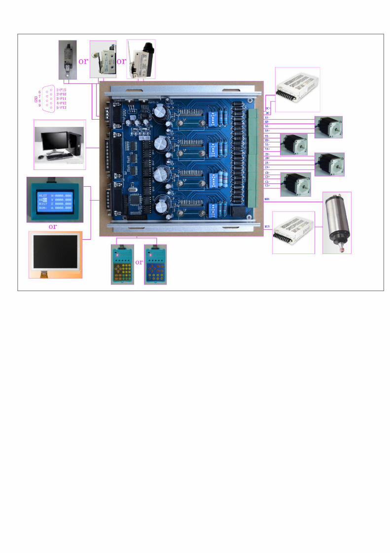
HY-TB4DV-T professional-type four-axis drive board manual
Product Link:
http://www.thanksbuyer.com/cnc-professional-4-a
xis-tb6600-5a-lathe-stepper-motor-driver-contro
ller-for-engraving-machine-24894
Thank you for choosing our company's products, the use of CNC
products better and faster for you, please read this manuaI
Features: Features
1: integrated high-speed microcomputer intelligent control chip, with plug-in
LCD display and hand, automatically detect the computer to automatically control
the movement of the shield handle control functions, digital can simultaneously
track record computer data and handle control mobile data
2: the path of the computer tracking records, time records can be run in
the computer processing to save the processed data off-line automatic repeat
the processing run
3: Manually move the processing and record keeping, traceability records
manually move the machine data, and automatically repeat the process run
manually move the path.
4: manual data input processing path, and run automatically enter the
path .
5: The driver XYZ-axis or Z axis of the knife can be done automatically,
without complex computer software operation
6: up to 5A stepper motor drive current, adjustable.
7: up to 16 segments, more accurate, run more smoothly.
8: overload automatic protection function of the flow through the warm,
protect your computer and peripherals .
9: bipolar constant-current chopper drive, low speed creeping phenomenon,
noise, non-resonant region.
10: a closed optical isolation, two-stage signal processing, to fully
protect your computer and equipment.
11:1 the road 0-10V/PWM governor signal output .
12: Rd input control, you can set the limit stop, which is divided into
the knife.
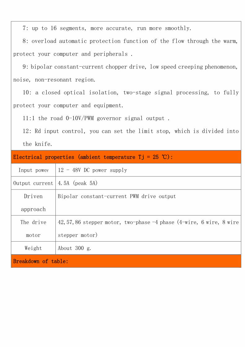
Electrical properties (ambient temperature Tj = 25 ℃):
Input power 12 - 48V DC power supply
Output current 4.5A (peak 5A)
Driven
approach
Bipolar constant-current PWM drive output
The drive
motor
42,57,86 stepper motor, two-phase -4 phase (4-wire, 6 wire, 8 wire
stepper motor)
Weight About 300 g.
Breakdown of table:
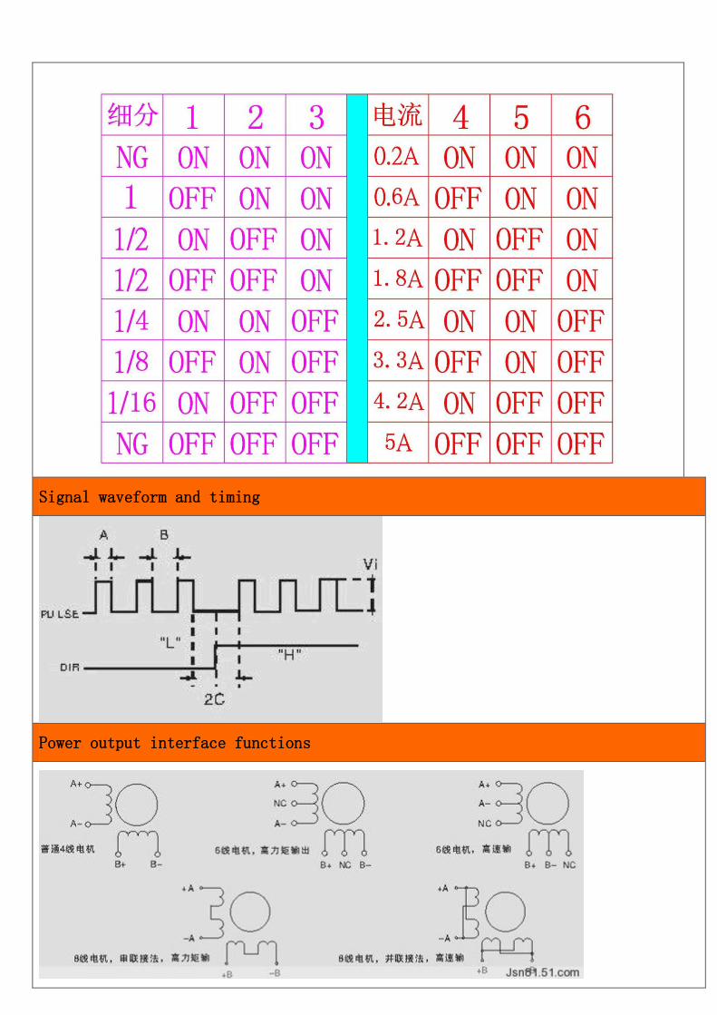
Signal waveform and timing
Power output interface functions
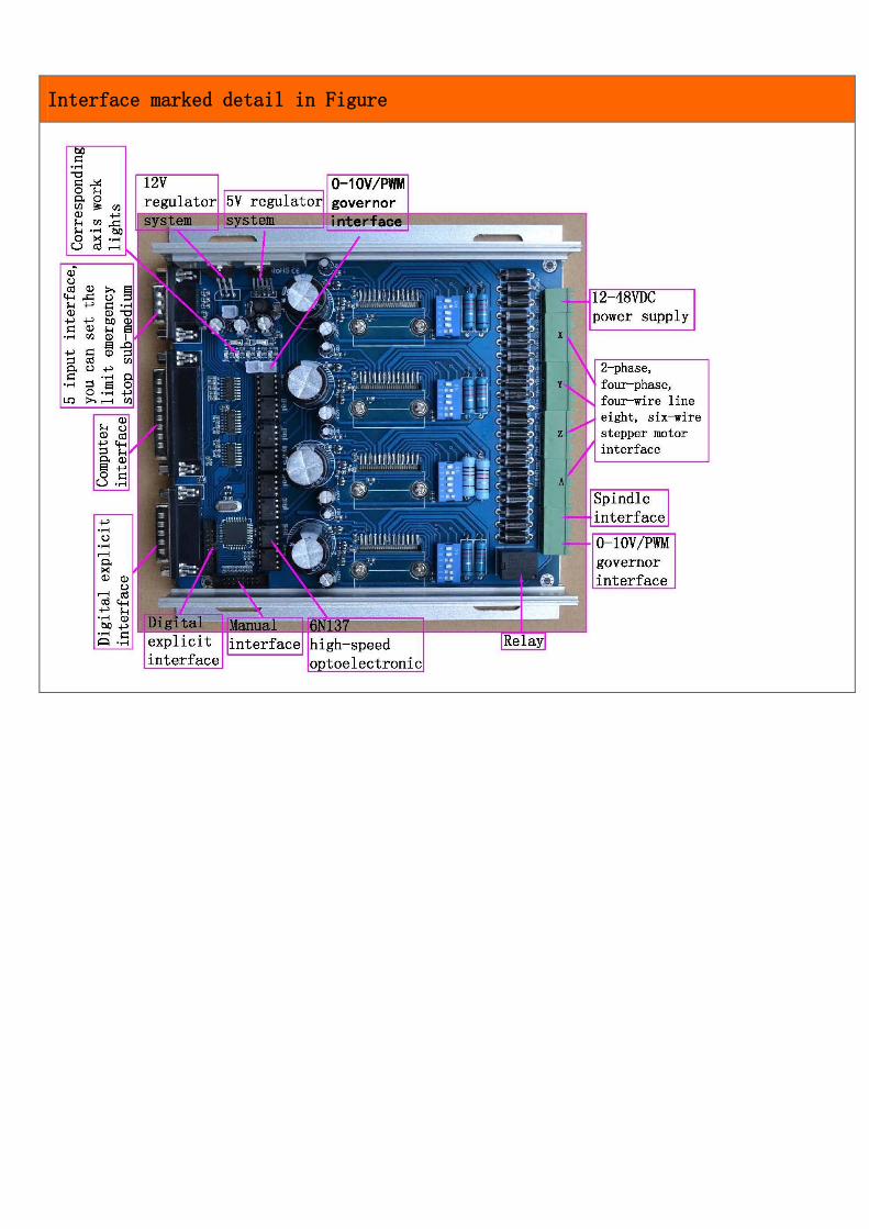
Interface marked detail in Figure
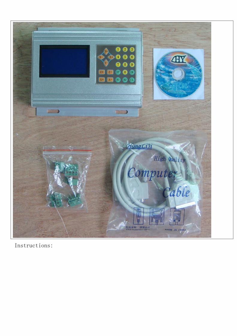
Instructions:
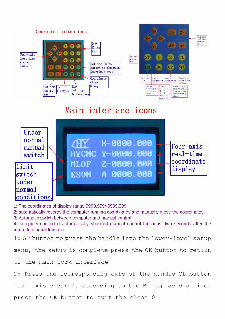
1: The coordinates of display range 9999.999/-9999.999
2: automatically records the computer running coordinates and manually move the coordinates
3: Automatic switch between computer and manual control
4: computer-controlled automatically shielded manual control functions, two seconds after the
return to manual function
1: ST button to press the handle into the lower-level setup
menu, the setup is complete press the OK button to return
to the main work interface
2: Press the corresponding axis of the handle CL button
four axis clear 0, according to the B1 replaced a line,
press the OK button to exit the clear 0
3: The four-axis real-time recording computer running
coordinates and manually move the coordinate value of the
computer running data + manually move data
===================================================
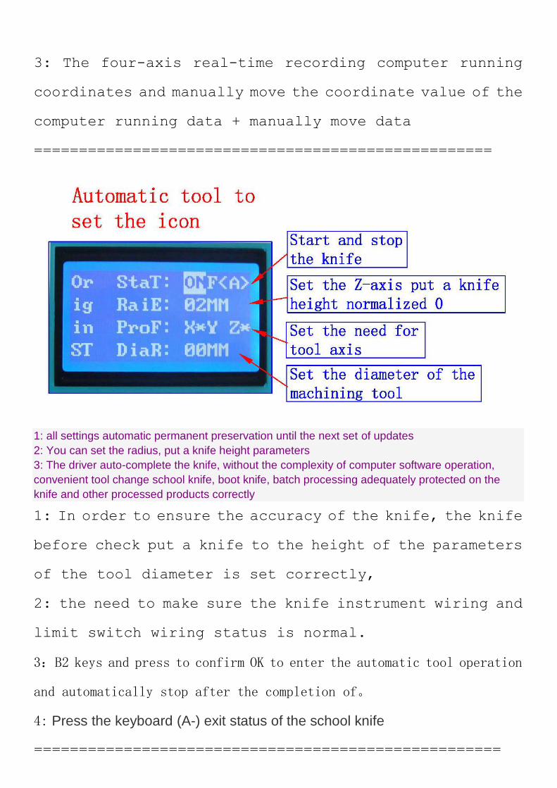
1: all settings automatic permanent preservation until the next set of updates
2: You can set the radius, put a knife height parameters
3: The driver auto-complete the knife, without the complexity of computer software operation,
convenient tool change school knife, boot knife, batch processing adequately protected on the
knife and other processed products correctly
1: In order to ensure the accuracy of the knife, the knife
before check put a knife to the height of the parameters
of the tool diameter is set correctly,
2: the need to make sure the knife instrument wiring and
limit switch wiring status is normal.
3:B2 keys and press to confirm OK to enter the automatic tool operation
and automatically stop after the completion of。
4: Press the keyboard (A-) exit status of the school knife
====================================================
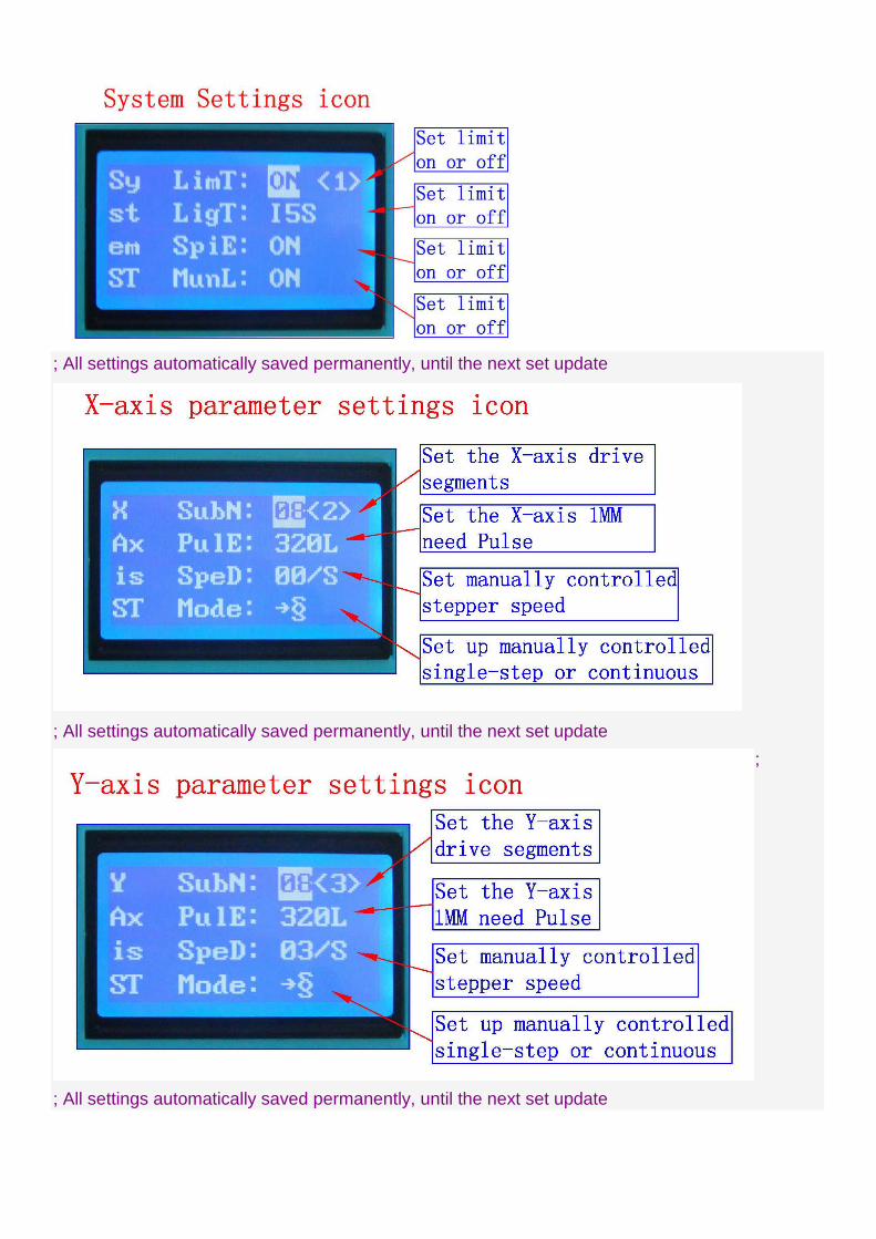
; All settings automatically saved permanently, until the next set update
; All settings automatically saved permanently, until the next set update
;
; All settings automatically saved permanently, until the next set update
; All settings automatically saved permanently, until the next set update
; All settings automatically saved permanently, until the next set update
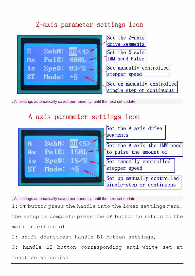
1: ST button press the handle into the lower settings menu,
the setup is complete press the OK button to return to the
main interface of
2: shift downstream handle B1 button settings,
3: handle B2 button corresponding anti-white set at
function selection
4: input handles digital keys to set the digital parameters
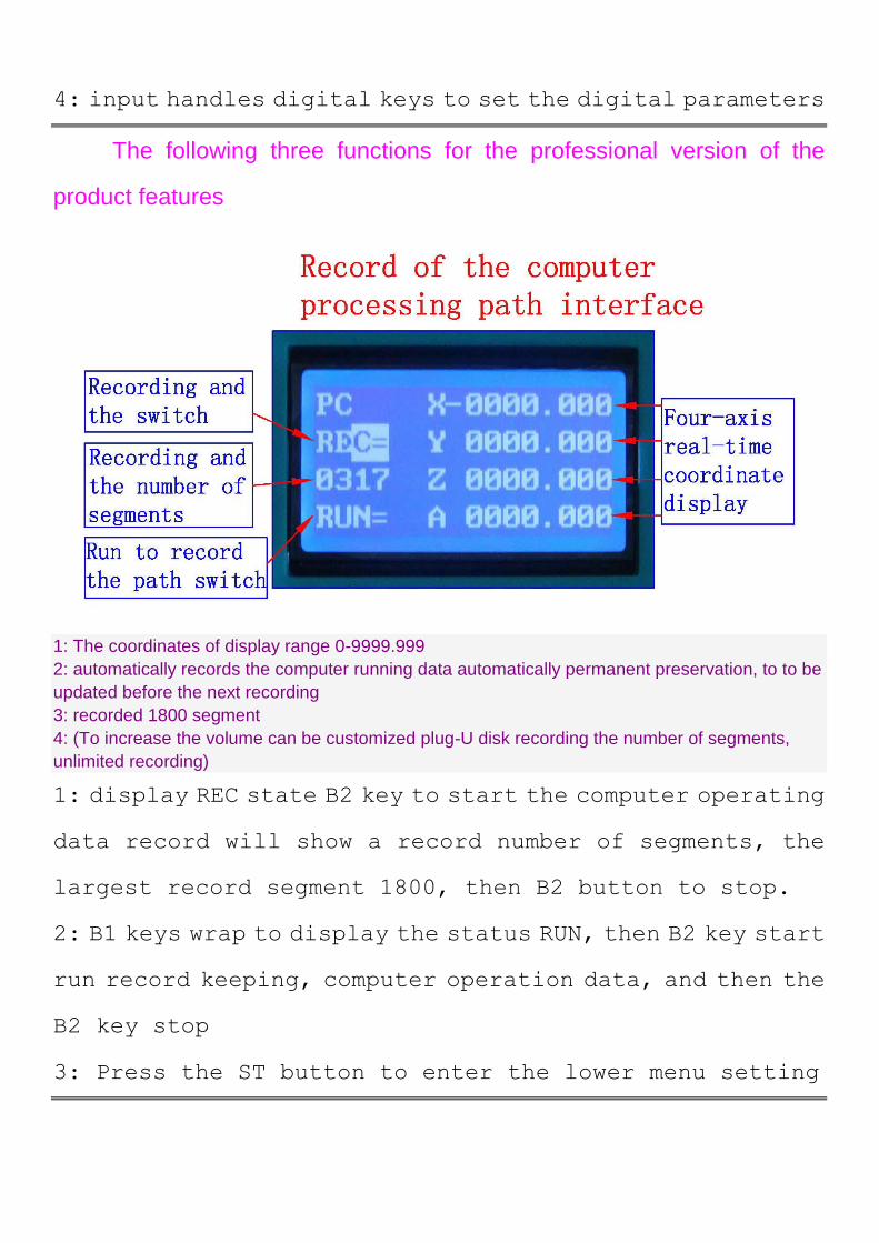
The following three functions for the professional version of the
product features
1: The coordinates of display range 0-9999.999
2: automatically records the computer running data automatically permanent preservation, to to be
updated before the next recording
3: recorded 1800 segment
4: (To increase the volume can be customized plug-U disk recording the number of segments,
unlimited recording)
1: display REC state B2 key to start the computer operating
data record will show a record number of segments, the
largest record segment 1800, then B2 button to stop.
2: B1 keys wrap to display the status RUN, then B2 key start
run record keeping, computer operation data, and then the
B2 key stop
3: Press the ST button to enter the lower menu setting
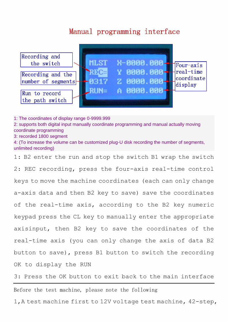
1: The coordinates of display range 0-9999.999
2: supports both digital input manually coordinate programming and manual actually moving
coordinate programming
3: recorded 1800 segment
4: (To increase the volume can be customized plug-U disk recording the number of segments,
unlimited recording)
1: B2 enter the run and stop the switch B1 wrap the switch
2: REC recording, press the four-axis real-time control
keys to move the machine coordinates (each can only change
a-axis data and then B2 key to save) save the coordinates
of the real-time axis, according to the B2 key numeric
keypad press the CL key to manually enter the appropriate
axisinput, then B2 key to save the coordinates of the
real-time axis (you can only change the axis of data B2
button to save), press B1 button to switch the recording
OK to display the RUN
3: Press the OK button to exit back to the main interface
Before the test machine, please note the following
1,A test machine first to 12V voltage test machine, 42-step,
please with 12-16V/DC power 57 stepper choose 16-24V/DC
power, 86 stepper election 24-36V/DC power
2,the stepper motor power and current (model)
3, to determine the wiring of the stepper motor
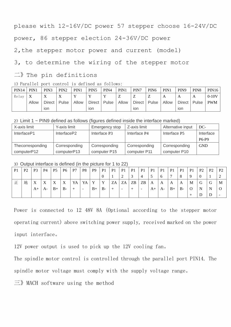
二》The pin definitions
1》Parallel port control is defined as follows:
PIN14 PIN1 PIN3 PIN2 PIN1 PIN5 PIN4 PIN1 PIN7 PIN6 PIN1 PIN9 PIN8 PIN16
Relay X
Allow
X
Direct
ion
X
Pulse
Y
Allow
Y
Direct
ion
Y
Pulse
Z
Allow
Z
Direct
ion
Z
Pulse
A
Allow
A
Direct
ion
A
Pulse
0-10V
PWM
2》Limit 1 ~ PIN9 defined as follows (figures defined inside the interface marked)
X-axis limit Y-axis limit Emergency stop Z-axis limit Alternative input DC-
InterfaceP1 InterfaceP2 Interface P3 Interface P4 Interface P5 Interface
P6-P9
Thecorresponding
computerP12
Corresponding
computerP13
Corresponding
computer P15
Corresponding
computer P11
Corresponding
computer P10
GND
3》Output interface is defined (in the picture for 1 to 22)
P1 P2 P3 P4 P5 P6 P7 P8 P9 P1
0
P1
1
P1
2
P1
3
P1
4
P1
5
P1
6
P1
7
P1
8
P1
9
P2
0
P2
1
P2
2
正 地 X
A+
X
A-
X
B+
X
B-
YA
+
YA
-
Y
B+
Y
B-
ZA
+
ZA
-
ZB
+
ZB
-
A
A+
A
A-
A
B+
A
B-
M
O
+
G
N
D
G
N
D
M
O
-
Power is connected to 12 48V 8A (Optional according to the stepper motor
operating current) above switching power supply, received marked on the power
input interface。
12V power output is used to pick up the 12V cooling fan。
The spindle motor control is controlled through the parallel port PIN14. The
spindle motor voltage must comply with the supply voltage range。
三》MACH software using the method
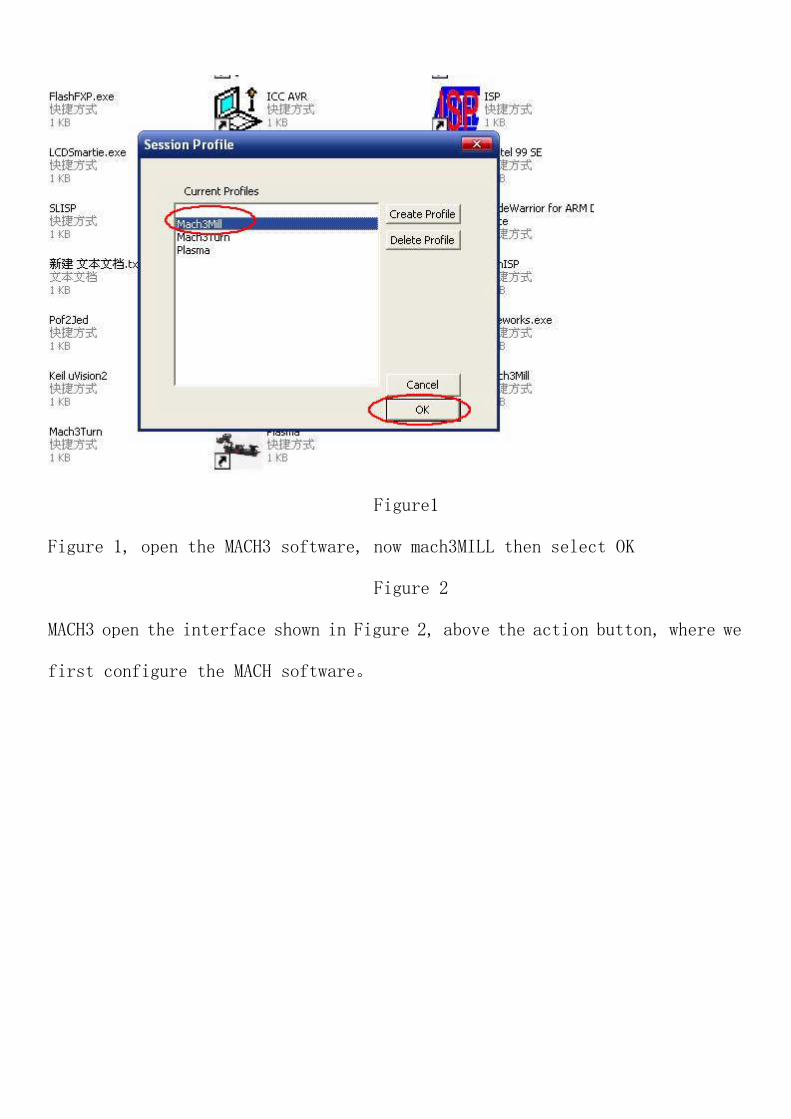
Figure1
Figure 1, open the MACH3 software, now mach3MILL then select OK
Figure 2
MACH3 open the interface shown in Figure 2, above the action button, where we
first configure the MACH software。
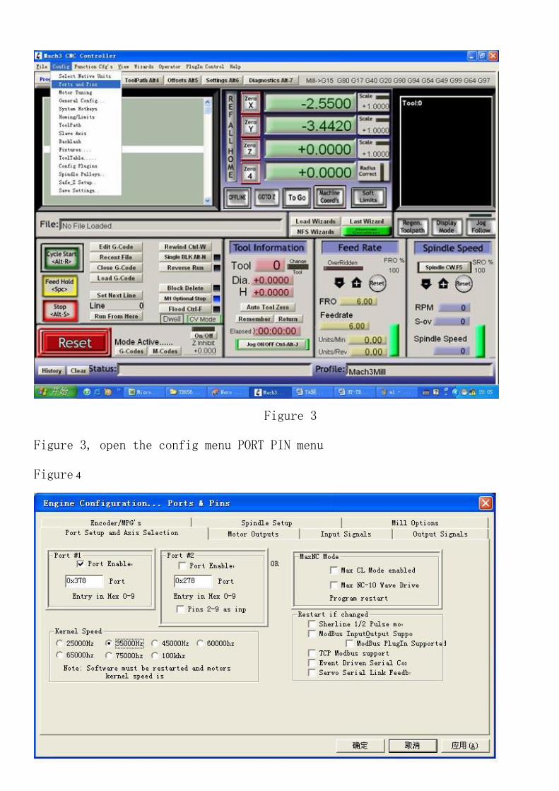
Figure 3
Figure 3, open the config menu PORT PIN menu
Figure 4
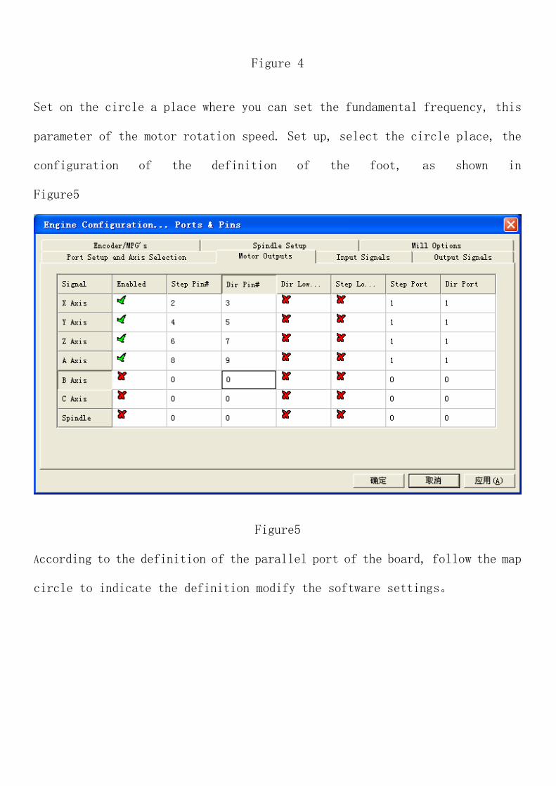
Figure 4
Set on the circle a place where you can set the fundamental frequency, this
parameter of the motor rotation speed. Set up, select the circle place, the
configuration of the definition of the foot, as shown in
Figure5
Figure5
According to the definition of the parallel port of the board, follow the map
circle to indicate the definition modify the software settings。
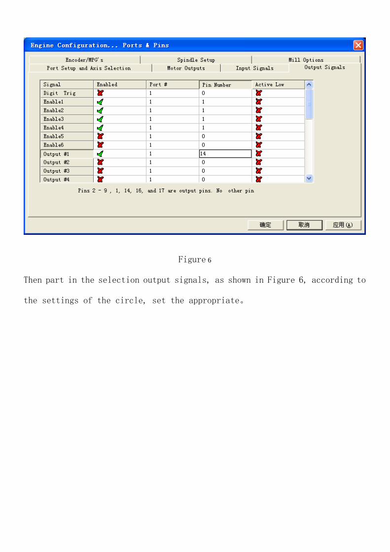
Figure 6
Then part in the selection output signals, as shown in Figure 6, according to
the settings of the circle, set the appropriate。
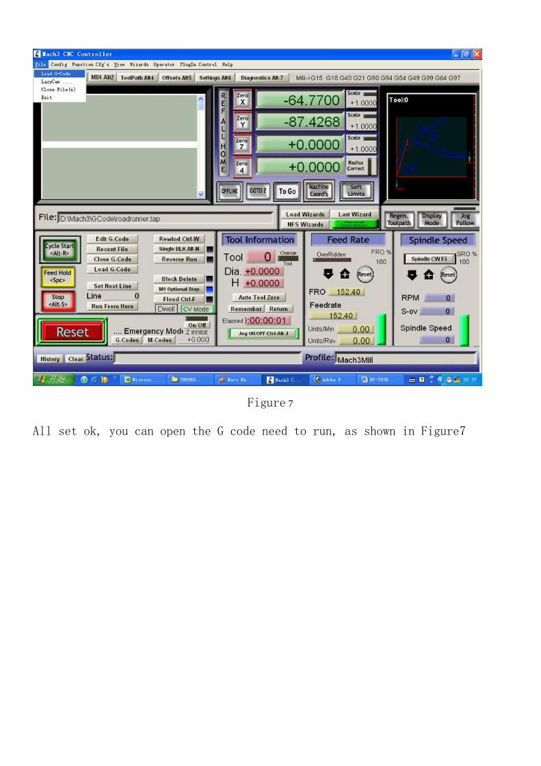
Figure 7
All set ok, you can open the G code need to run, as shown in Figure7
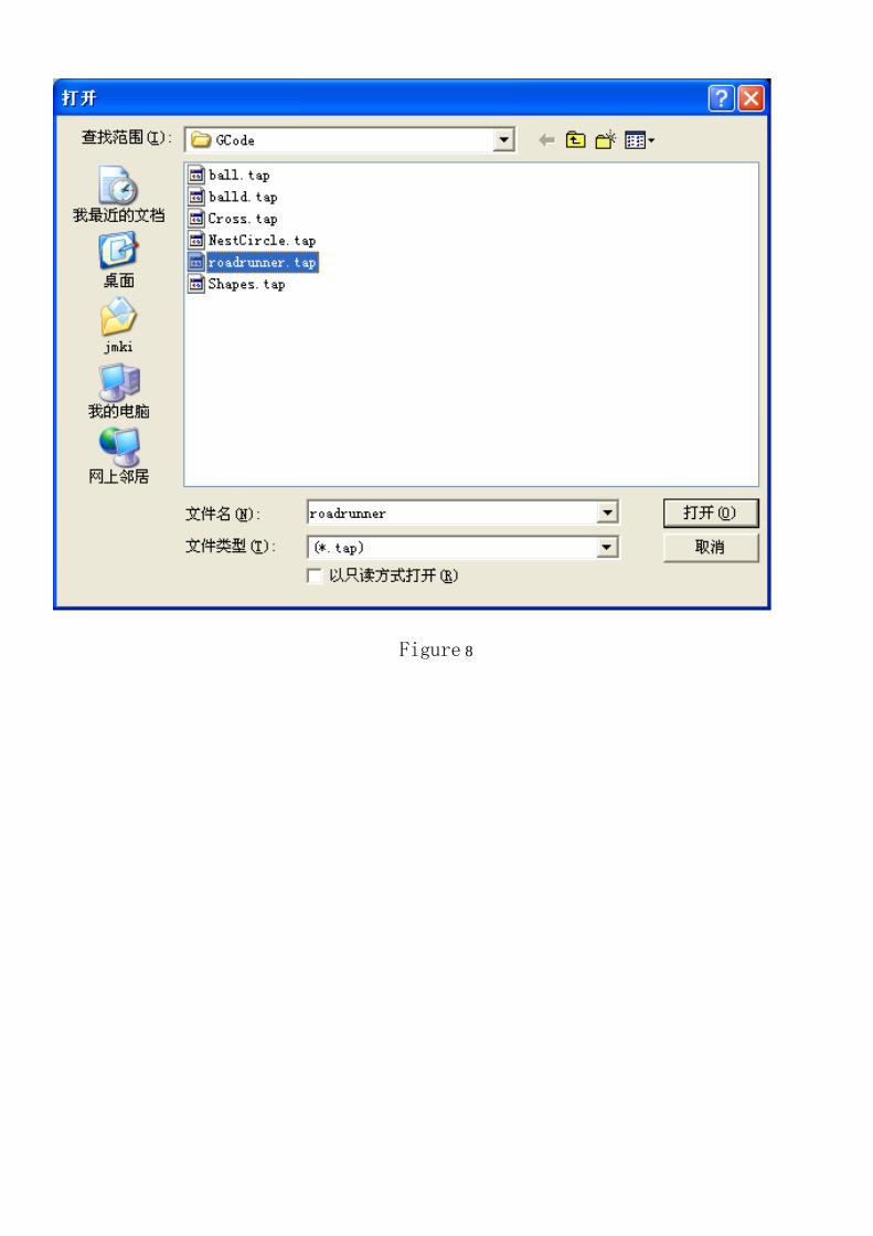
Figure 8
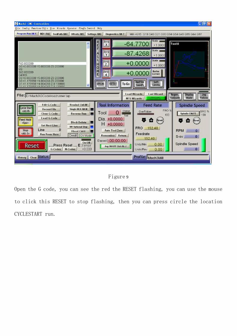
Figure 9
Open the G code, you can see the red the RESET flashing, you can use the mouse
to click this RESET to stop flashing, then you can press circle the location
CYCLESTART run.


![Traditional pest contro]: A retrospection](https://img.pdfslide.us/doc/110x75/61b345feb0fb065107790ef8/traditional-pest-contro-a-retrospection.jpg)