Embed Size (px)
Citation preview
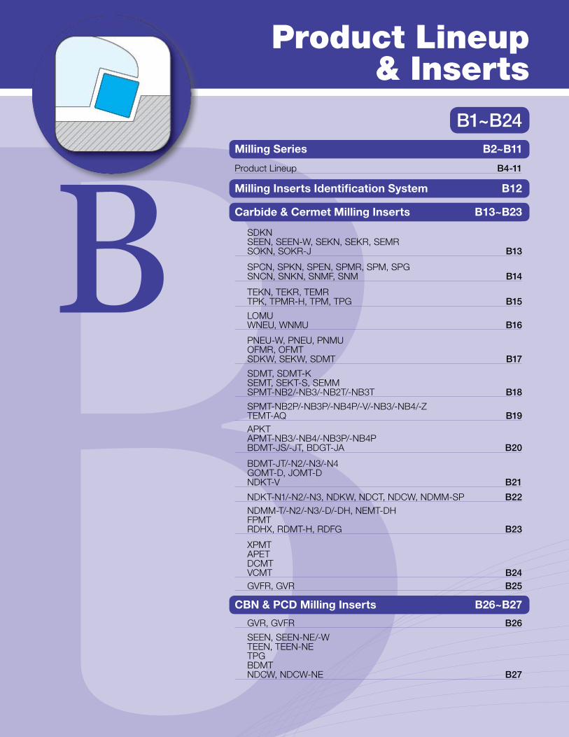
B1~B24
Product Lineup& Inserts
Milling Series B2~B11
Product Lineup B4-11
SDKN SEEN, SEEN-W, SEKN, SEKR, SEMR SOKN, SOKR-J B13
SPCN, SPKN, SPEN, SPMR, SPM, SPG SNCN, SNKN, SNMF, SNM B14
TEKN, TEKR, TEMR TPK, TPMR-H, TPM, TPG B15
LOMU WNEU, WNMU B16
PNEU-W, PNEU, PNMUOFMR, OFMT SDKW, SEKW, SDMT B17
SDMT, SDMT-KSEMT, SEKT-S, SEMMSPMT-NB2/-NB3/-NB2T/-NB3T B18
SPMT-NB2P/-NB3P/-NB4P/-V/-NB3/-NB4/-ZTEMT-AQ B19APKTAPMT-NB3/-NB4/-NB3P/-NB4P BDMT-JS/-JT, BDGT-JA B20
BDMT-JT/-N2/-N3/-N4GOMT-D, JOMT-D NDKT-V B21
NDKT-N1/-N2/-N3, NDKW, NDCT, NDCW, NDMM-SP B22NDMM-T/-N2/-N3/-D/-DH, NEMT-DH FPMT RDHX, RDMT-H, RDFG B23
XPMTAPETDCMTVCMT B24GVFR, GVR B25
GVR, GVFR B26
SEEN, SEEN-NE/-WTEEN, TEEN-NETPGBDMTNDCW, NDCW-NE B27
Milling Inserts Identification System B12
Carbide & Cermet Milling Inserts B13~B23
CBN & PCD Milling Inserts B26~B27

B2 B3
B
Pro
duct
Lin
eup
& In
sert
s
B
Pro
duct
Lin
eup
& In
sert
s
M-FOUR (MEW) M-SIX (MFWN)
1. Economical 4-edge Insert2. Kyocera’s unique mold technology reduces cutting force
1. Economical 6-edge Insert2. Tough Cutting Edge due to Thick Edge DesignRef. page E2 Ref. page E10
� High Efficiency Endmill MECX
New Face Mills are now available
� Helical Endmill MECH
High efficiency cutting is achieved with large axial D.O.C.'s
MECH solves problems with heavy cutting
Endmill & Shell Mill Designs, Intergral Arbor Styles, and Head Exchangable
Designs Available
Low cutting force JS chipbreaker
Expanded Lineup
PR1225 for Stainless Steel(Fine grain carbide material)
JA Chipbreaker for Aluminum cutting
Low Cutting Forces
Superior Wall Surface
True 90º Shoulders
Superior Wall Surface
Enable high efficiency cutting on turning mills and small machining centers
Multi-Flute Face Mills Available for Improved Efficiency Expanded Insert Lineup
Ref. page E32
Ref. page E20 Ref. page E36
Head exchangeable design
Improved Productivity with Notched Inserts!
Double-sided 4-edge insert, Newly Developed Endmill Double-sided 6-edge insert, Low Cutting Force 0°-Lead Cutter
� High Efficiency Endmill MEC
Product Lineup
B2 B3
B
Pro
duct
Lin
eup
& In
sert
s
B
Pro
duct
Lin
eup
& In
sert
s
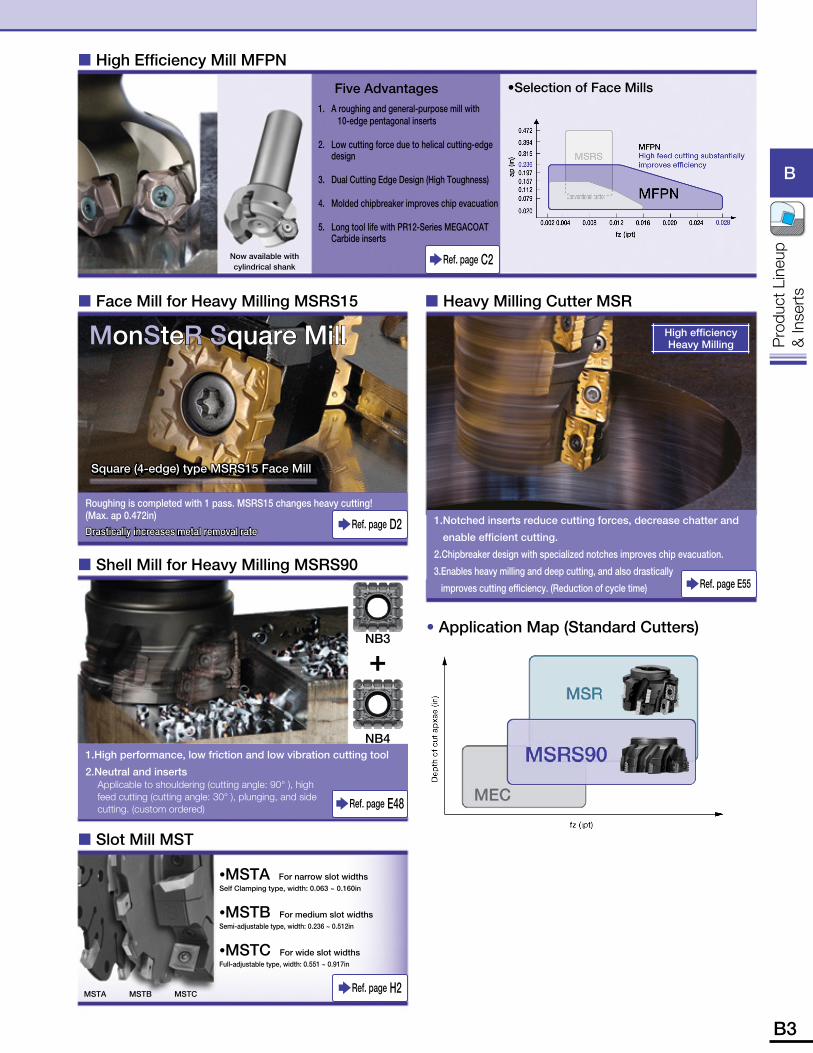
� Slot Mill MST
•MSTA For narrow slot widthsSelf Clamping type, width: 0.063 ~ 0.160in
•MSTB For medium slot widthsSemi-adjustable type, width: 0.236 ~ 0.512in
•MSTC For wide slot widthsFull-adjustable type, width: 0.551 ~ 0.917in
Ref. page H2MSTA MSTB MSTC
� Face Mill for Heavy Milling MSRS15
Square (4-edge) type MSRS15 Face Mill
Roughing is completed with 1 pass. MSRS15 changes heavy cutting!(Max. ap 0.472in)Drastically increases metal removal rate
MonSteR Square Mill
Ref. page D2
� Heavy Milling Cutter MSR
High efficiency Heavy Milling
1. Notched inserts reduce cutting forces, decrease chatter and
enable efficient cutting.
2. Chipbreaker design with specialized notches improves chip evacuation.
3. Enables heavy milling and deep cutting, and also drastically
improves cutting efficiency. (Reduction of cycle time) Ref. page E55� Shell Mill for Heavy Milling MSRS90
� High Efficiency Mill MFPN
•Selection of Face Mills
Ref. page C2
1. A roughing and general-purpose mill with 10-edge pentagonal inserts
2. Low cutting force due to helical cutting-edge design
3. Dual Cutting Edge Design (High Toughness)
4. Molded chipbreaker improves chip evacuation
5. Long tool life with PR12-Series MEGACOAT Carbide inserts
Five Advantages
Now available with cylindrical shank
NB3
+
NB41. High performance, low friction and low vibration cutting tool
2. Neutral and insertsApplicable to shouldering (cutting angle: 90° ), high feed cutting (cutting angle: 30° ), plunging, and side cutting. (custom ordered) Ref. page E48
• Application Map (Standard Cutters)
B4 B5
B
Pro
duct
Lin
eup
& In
sert
s
B
Pro
duct
Lin
eup
& In
sert
s
D9
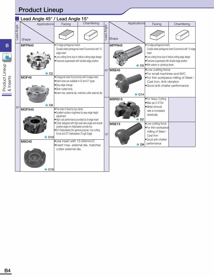
� Lead Angle 45° / Lead Angle 15°Applications
Shape
Facing Chamfering
MFPN45 • 10-edge pentagonal insertsDouble-sided pentagonal insert Economical with 10-edge insert
• Low cutting force due to helical cutting-edge design• Fractures suppressed with double-edge position• With weldon or cylindrical shank
MSE45 • Low cutting force• For small machines and M/C• For thin workpiece milling of Steel /
Cast Iron, Anti-vibration• Good anti-chatter performance
MSRS15 • For Heavy Cutting•Max ap 0.472in•Metal removal
rate is increased drastically
MSE15 • Low cutting force• For thin workpiece
milling of Steel / Cast Iron
• Good anti-chatter performance
C12
C9
C15
C14
D2
C2
C5
Applications
Shape
Facing Chamfering
MFPN45 • 10-edge pentagonal insertsDouble-sided pentagonal insert Economical with 10-edge insert
• Low cutting force due to helical cutting-edge design• Fractures suppressed with double-edge position
MOF45 • Octagonal Insert Economical with 8-edge insert• Insert sizes are available in 05 and 07 types• Easy edge change• Silver coated body• Insert max. external dia. matches cutter external dia.
MOFX45 • The insert is fixed by top clamp• Excellent surface roughness by easy edge height
adjustment• High cost performance provided by 8-edge insert• Cutter designed with high axial rake angle and double
positive angle on chipbreaker provide low• SH Chipbreakers (for general purpose / low cutting
force) and GT chipbreakers (Tough Edge)
MSO45 • Use insert with 13.494mm/C• Insert max. external dia. matches
cutter external dia.
Lead
Ang
le
45°Le
ad A
ngle
45°
15°
Product Lineup
B4 B5
B
Pro
duct
Lin
eup
& In
sert
s
B
Pro
duct
Lin
eup
& In
sert
s
Applications
Shape
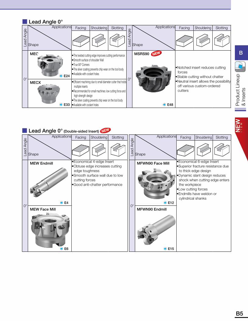
Facing Shouldering Slotting
MSRS90
• Notched insert reduces cutting forces
• Stable cutting without chatter• Neutral insert allows the possibility
off various custom-ordered cutters
Applications
Shape
Facing Shouldering Slotting
MEC • The twisted cutting edge improves cutting performance• Smooth surface of shoulder Wall• True 90º Corners• The silver coating prevents chip wear on the tool body• Available with coolant holes
MECX • Efficient machining due to small diameter cutter that holds multiple inserts
• Recommended for small machines: low cutting force and high strength design
• The silver coating prevents chip wear on the tool body• Available with coolant holes
� Lead Angle 0°
� Lead Angle 0° (Double-sided Insert)
E24
E33 E48
Lead
Ang
le
0°
Lead
Ang
le
0°
Applications
Shape
Facing Shouldering Slotting
MEW Endmill
E4
•Economical 4-edge Insert• Obtuse edge increases cutting
edge toughness • Smooth surface wall due to low
cutting forces•Good anti-chatter performance
MEW Face Mill
E6
Lead
Ang
le
0°
Applications
Shape
Facing Shouldering Slotting
MFWN90 Face Mill
E12
•Economical 6-edge Insert• Superior fracture resistance due
to thick edge design• Dynamic slant design reduces
shock when cutting edge enters the workpiece
• Low cutting forces• Endmills have weldon or
cylindrical shanks
MFWN90 Endmill
E15
Lead
Ang
le
0°
B6 B7
B
Pro
duct
Lin
eup
& In
sert
s
B
Pro
duct
Lin
eup
& In
sert
s
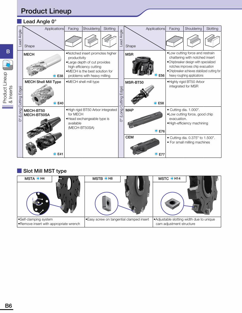
Applications
Shape
Facing Shouldering Slotting
• Notched insert promotes higher productivity
• Large depth of cut provides high efficiency cutting
• MECH is the best solution for problems with heavy milling
•MECH shell mill type
• High rigid BT50 Arbor integrated for MECH
•Head exchangeable type is available (MECH-BT50SA)
E56
MSR
E77
CEM
E58
MSR-BT50
Applications
Shape
Facing Shouldering Slotting
• Low cutting force and restrain chattering with notched insert
• Chipbreaker design with specialized notches improves chip evacuation
• Chipbreaker achieves stabilized cutting for heavy roughing applications
• Highly rigid BT50 Arbor integrated for MSR
• Cutting dia. 1.000".• Low cutting force, good chip
evacuation.• High-efficiency machining
• Cutting dia. 0.375" to 1.500".• For small milling machines
E76
MAP
Lead
Ang
le0°
(Lon
g C
uttin
g Ed
ge)
Lead
Ang
le0°
(Lon
g C
uttin
g Ed
ge)
MSTA H4 MSTB H8 MSTC H14
•Self-clamping system•Remove insert with appropriate wrench
• Easy screw on tangential clamped insert • Adjustable slotting width due to unique cam adjustment structure
� Slot Mill MST type
E40
MECH Shell Mill Type
E41
MECH-BT50MECH-BT50SA
� Lead Angle 0°
E38
MECH
Product Lineup
B6 B7
B
Pro
duct
Lin
eup
& In
sert
s
B
Pro
duct
Lin
eup
& In
sert
s
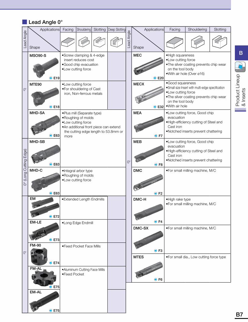
Applications
Shape
Facing Shouldering Slotting
MEC • High squareness•Low cutting force• The silver coating prevents chip wear on the tool body
•With air hole (Over ø16)
MECX •Good squareness• Small size Insert with multi-edge specification•Low cutting force• The silver coating prevents chip wear on the tool body
•With air hole
MEA • Low cutting force, Good chip evacuation
• High-efficiency cutting of Steel and Cast iron
• Notched inserts prevent chattering
MEB • Low cutting force, Good chip evacuation
• High-efficiency cutting of Steel and Cast iron
• Notched inserts prevent chattering
DMC •For small milling machine, M/C
DMC-H •High rake type•For small milling machine, M/C
DMC-SX • For small milling machine, M/C
MTES •For small dia., Low cutting force type
Applications
Shape
Facing Shouldering Slotting Deep Slotting
• Screw clamping & 4-edge insert reduces cost
•Good chip evacuation•Low cutting force
• Low cutting force• For shouldering of Cast
iron, Non-ferrous metals
• Plus mill (Separate type)•Roughing of molds•Low cutting force• An additional front piece can extend
the cutting edge length to 53.8mm or more
•Integral arbor type•Roughing of molds•Low cutting force
� Lead Angle 0°Le
ad A
ngle
0° (L
ong
Cut
ting
Edge
)
0°
E19
E18
E63
E63
E63
MHD-C
MHD-SB
MHD-SA
MTE90
E75
Lead
Ang
le
0°
E20
E32
F7
F8
F2
F4
E75
F3
F6
MSO90-S
• Extended Length Endmills
• Long Edge Endmill
• Fixed Pocket Face Mills
•Aluminum Cutting Face Mills•Fixed Pocket
0°
E72
E73
E74
FM-AL
EM-AL
EM
EM-LE
FM-90
B8 B9
B
Pro
duct
Lin
eup
& In
sert
s
B
Pro
duct
Lin
eup
& In
sert
s
Applications
Shape
Facing Shouldering Slotting Deep Slotting Pocketing DrillingLead
Angle and Max ap
Cutting Dia. øD
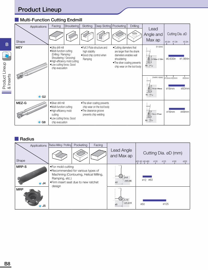
• Ultra drill mill• Multi-function cutting
(Drilling / Ramping / Shouldering / Grooving)
• High-efficiency mold cutting• Low cutting force, Good
chip evacuation
• Full 2-Flute structure and high stability
• Good chip control when Ramping
• Cutting diameters that are larger than the shank diameters enables wall shouldering
• The silver coating prevents chip wear on the tool body
MEZ-G • Silver drill mill• Multi-function cutting• High-efficiency mold
cutting• Low cutting force, Good
chip evacuation
• The silver coating prevents chip wear on the tool body
• The clearance groove prevents chip welding
Applications
Shape
Radius Milling / Profiling Pocketing Facing
Lead Angle and Max ap
Cutting Dia. øD (mm)
MRP-S •For mold cutting• Recommended for various types of
Machining (Contouring, Helical Milling, Ramping, etc.)
•Firm insert seat due to new ratchet design
MRP
� Multi-Function Cutting Endmill
MEY
ø2.0inø1.0inø0.5in
ø50mmø25mmø10mm
ø16mm ø50mm
ø0.630in ø1.984in
ø16mm ø49mm
G2
G8
� Radius
ø50 ø125
ø32 ø80 ø125 ø200
J4
J5
ø12 ø63
ø50 ø160ø63 ø100
(in sizes)
(metric sizes)
Product Lineup
B8 B9
B
Pro
duct
Lin
eup
& In
sert
s
B
Pro
duct
Lin
eup
& In
sert
s
� Chamfering
Applications
Shape
Contouring / Profiling Pocketing
Lead Angle and Max ap
Cutting Dia. ØD (mm)
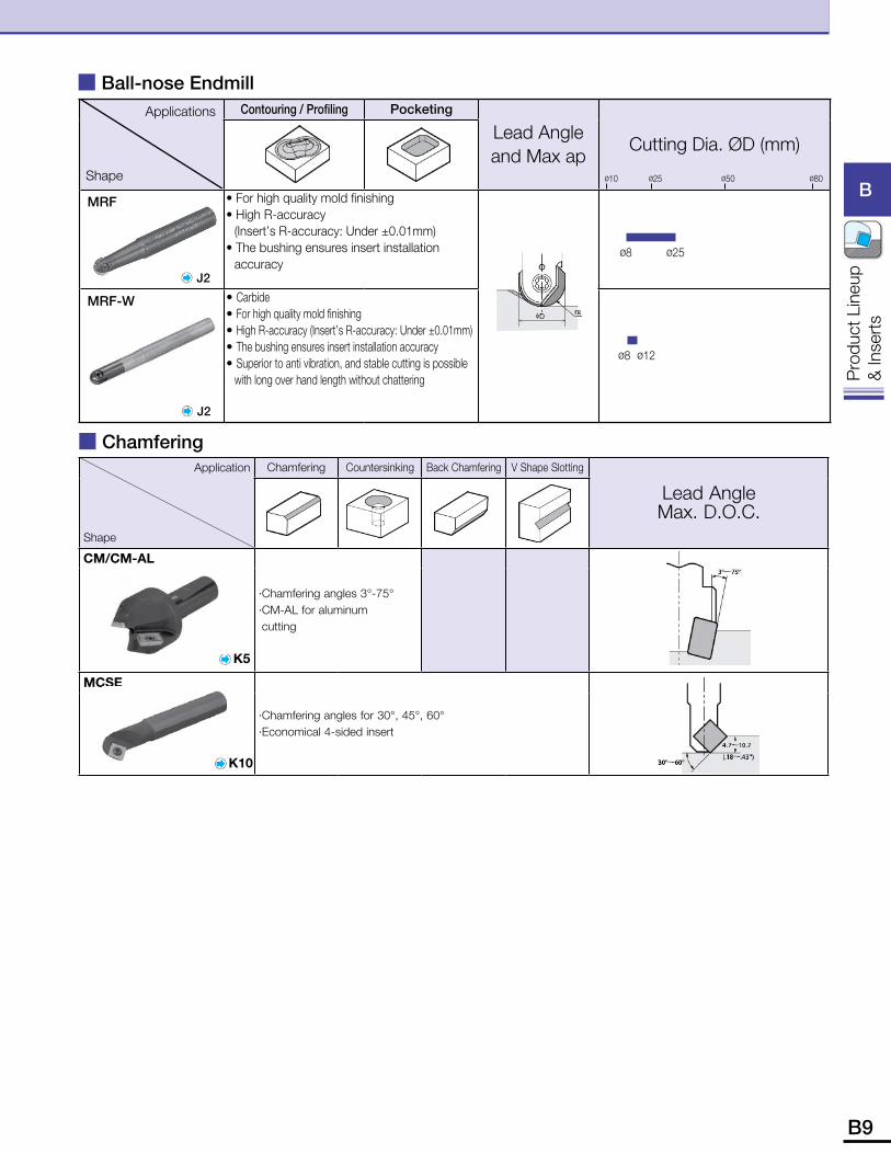
MRF • For high quality mold finishing• High R-accuracy
(Insert’s R-accuracy: Under ±0.01mm)• The bushing ensures insert installation
accuracy
MRF-W • Carbide• For high quality mold finishing• High R-accuracy (Insert’s R-accuracy: Under ±0.01mm)• The bushing ensures insert installation accuracy• Superior to anti vibration, and stable cutting is possible
with long over hand length without chattering
� Ball-nose Endmill
J2
ø8 ø25
ø8 ø12
ø10 ø25 ø50 ø80
J2
Application
Shape
Chamfering Countersinking Back Chamfering V Shape Slotting
Lead Angle Max. D.O.C.
CM/CM-AL
· Chamfering angles 3°-75°· CM-AL for aluminum cutting
K5
MCSE
· Chamfering angles for 30°, 45°, 60°· Economical 4-sided insert
K10
B10 B11
B
Pro
duct
Lin
eup
& In
sert
s
B
Pro
duct
Lin
eup
& In
sert
s
Applications
Shape
Bolt Countersinking Facing Shouldering
Lead Angle and Max ap
Cutting Dia. øD (mm)
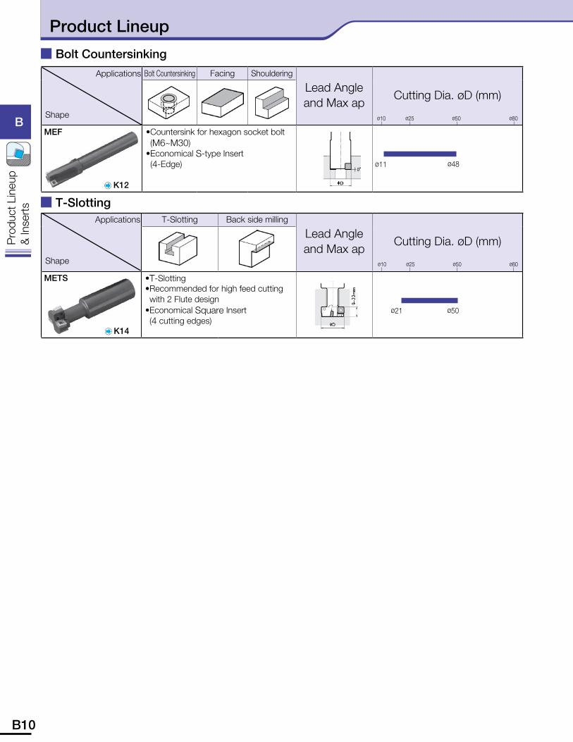
MEF • Countersink for hexagon socket bolt (M6~M30)
• Economical S-type Insert (4-Edge)
� Bolt Countersinking
K12
ø11 ø48
ø10 ø25 ø50 ø80
Applications
Shape
T-Slotting Back side milling
Lead Angle and Max ap
Cutting Dia. øD (mm)
METS •T-Slotting• Recommended for high feed cutting with 2 Flute design
• Economical Square Insert (4 cutting edges)
� T-Slotting
K14
ø21 ø50
ø10 ø25 ø50 ø80
Product Lineup
B10 B11
B
Pro
duct
Lin
eup
& In
sert
s
B
Pro
duct
Lin
eup
& In
sert
s
Application
Shape
API Ring Grooving
Application
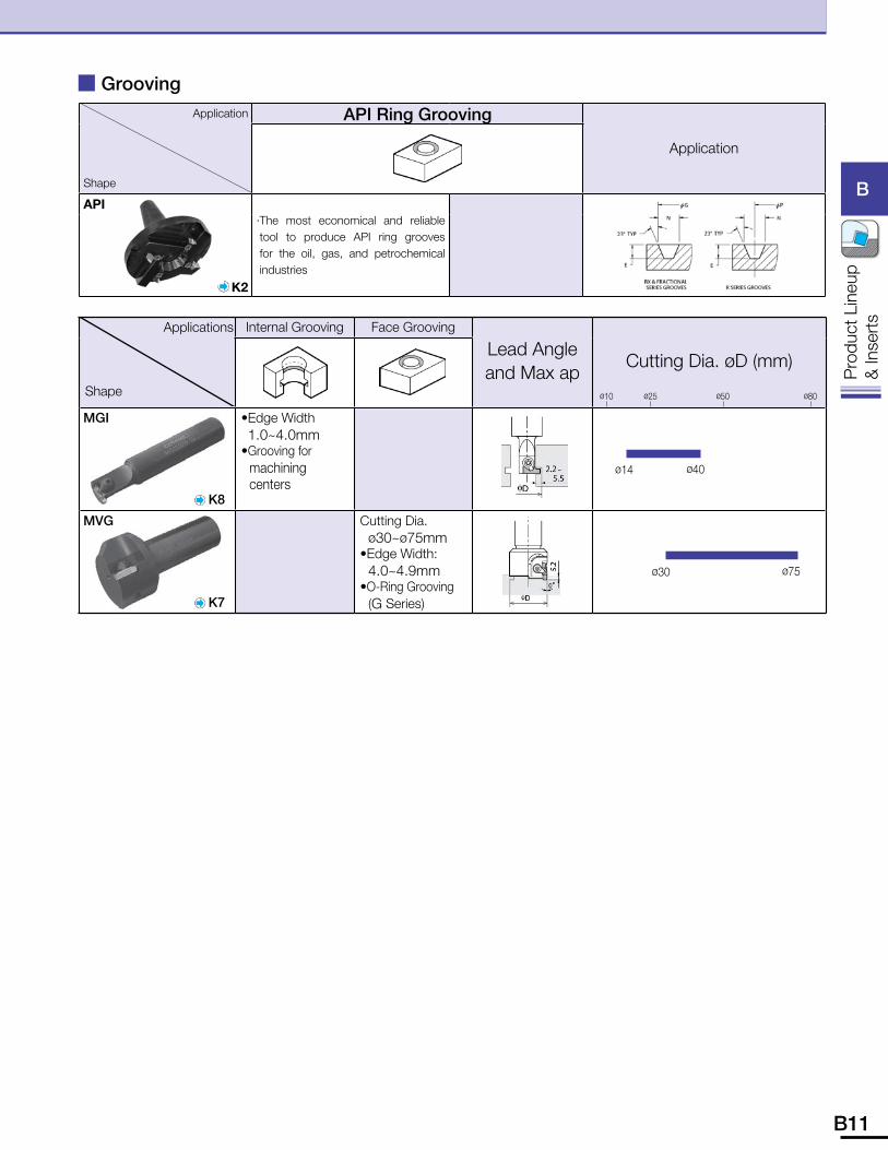
API· The most economical and reliable tool to produce API ring grooves for the oil, gas, and petrochemical industries
K2
Applications
Shape
Internal Grooving Face Grooving
Lead Angle and Max ap
Cutting Dia. øD (mm)
MGI • Edge Width•1.0~4.0mm• Grooving for
machining centers
MVG Cutting Dia.ø30~ø75mm
• Edge Width:4.0~4.9mm
• O-Ring Grooving (G Series)
� Grooving
ø14 ø40
ø30 ø75
ø10 ø25 ø50 ø80
K8
K7
B12 B13
B
Pro
duct
Lin
eup
& In
sert
s
B
Pro
duct
Lin
eup
& In
sert
s
S
T
E
F
tEdge Length yThickness
06
Symbol
02
T3
03
05
04
6.35
2.38
T
3.18
3.97
5.56
4.76
86° Rhombic
87° Rhombic
80° Rhombic
82° Parallelogram
85° Parallelogram
T Triangle
Tq
qShape
Symbol
R
S
P
O
N
M
L
H
C
B
A
Round
Square
Pentagon
Octagon
Hexagon
Shape
S 11-20
e
K
wRelief Angle
w
Pr
N
11-17
11-14
0-20
0-17
0-14
L
R
M
N
A
B
P
D
E
F
J
H
K
G
C .5 (1)
.6
1 (2)
1.2
1.5 (3)
2
2.5
3
3.5
4
5
6
7
8
Symbol
1/32
.040
1/16
5.64
3/32
1/8
5/32
3/16
7/32
1/4
5/16
3/8
7/16
1/2
Size
0
3
6
11
15
20
25
30
0-11
7
uiCutting Edge Angle / Relief Angle / Corner-R
uiCorner-R
0.4
0.8
2.0
1.6
1.2
04
08
16
20
12
uCutting Edge Angle
X
D
A
F
E
P
H
65°
45°
60°
87°
90°
75°
85°
22°
23°
iRelief Angle
30°
25°
20°
N
R
P
U
T
S
A
B
C
D
F
G
E
0°
10°
11°
14°
3°
5°
7°
15°
P
yThickness
1.2 (5)
1.5 (6)
1.8 (7)
2
2.5
3
3.5
4
4.5
5
5.5
6
7
8
10
Symbol
5/32
3/16
7/32
1/4
5/16
3/8
7/16
1/2
9/16
5/8
11/16
3/4
7/8
1
11/4
IC
tIC Size
t
16y
03
Symbol Shape
Symbol Shape
A
D
rType
iu o
T
M
R
N
F L
R
Symbol Hand
Right
Left
N Without Hand
!0Tool Hand
!0
R
T
ISO
ANSIq e
Kw
PrN– P
t
3y
2 3iu o !0
R
Chamfer+ R-honed
2-side Chipbreakers,Without Hole
No Chipbreaker,Without Hole
1-side Chipbreaker,Without Hole
1-side Chipbreaker,With Hole
No Chipbreaker,With Hole
oEdge Preparation
Chamfer
R-honed
Sharp Edge
Relief Angle(°)Symbol
eTolerance
A
B
C
D
E
G
K
M
U
R
S
0.0002
0.0002
0.0005
0.0005
0.001
0.001
0.0005
0.003 to 0.008
.005 to .015
-Blank with grind stock on allsurfaces.-Blank with grind stock on topand bottom surfaces only.
0.001
0.001
0.001
0.001
0.001
0.001
0.002 to 0.006
.002 to .006
.003 to .010
B(±) IC(±)
0.001
0.005
0.001
0.001
0.001
0.005
0.001
0.005
0.005
T(±)
Corner Height IC Size Thickness
Tolerance
Rectangle
o
OtherCondition
iCutting Point Size
NR
C
R
R
R
R
T
R
S
2
T
3
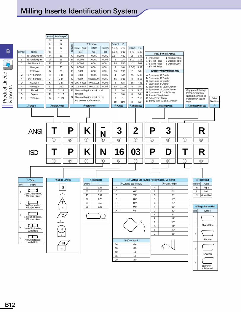
Only appears following a letter in sixth position. Number of 1/64ths of an inch in primary faceted edge.
uCutting Point
INSERT WITH RADIUS
INSERTS WITH WIPER FLATS
Sharp Corner1/64 Inch Radius1/32 Inch Radius3/64 Inch Radius
0-1-2-3-
Square Insert 45° ChamferSquare Insert 30° ChamferSquare Insert 15° ChamferSquare Insert 3° ChamferSquare Insert 30° Double ChamferSquare Insert 15° Double ChamferSquare Insert 3° Double ChamferTruncated Triangle InsertFlatted Corner TriangleTriangle Insert 15° Double Chamfer
A-D-E-F-K-L-M-N-P-X-
1/16 Inch Radius3/32 Inch Radius1/8 Inch Radius
4-6-8-
Sym
bol
Milling Inserts Identification System
B12 B13
B
Pro
duct
Lin
eup
& In
sert
s
B
Pro
duct
Lin
eup
& In
sert
s
ZX
β
α
A
γT
Classification of usage PCarbon Steel / Alloy Steel � � � � �
Ref
. Pag
e fo
r App
licab
le
Tool
hold
ers
Mold Steel � � � � �
� : Roughing / 1st Choice� : Roughing / 2nd Choice� : Finishing / 1st Choice� : Finishing / 2nd Choice(In case hardness is under 45HRC)
M Stainless Steel � � �
KGray Cast Iron � � �Nodular Cast Iron � �
N Non-ferrous Metals �
SHeat-resistant Alloys � � �Titanium Alloys � �
H Hard Materials � � �
InsertHanded Insert shows Right-hand
Description
Dimension (inch) Angle(°) Cermet MEGACOAT PVD Coated Carbide Carbide
A T X Z r� � � �
TN60
TN10
0MTC
60M
PR
1225
PR
1210
PR
630
PR
730
PR
830
PR
1025
PR
660
PR
905
PW
30K
W10
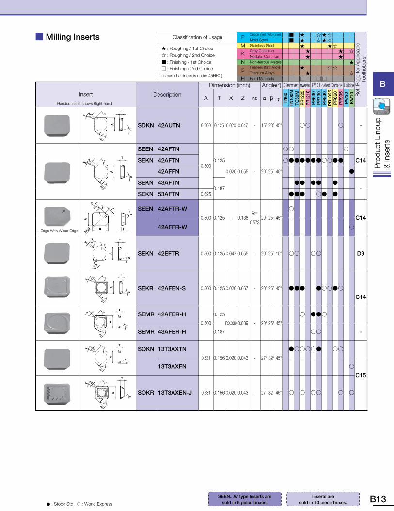
SDKN 42AUTN 0.500 0.125 0.020 0.047 - 15° 23° 45° �� � -
SEEN 42AFTN
0.5000.125
0.020 0.055 - 20° 25° 45°
�� �
C14SEKN 42AFTN �����������
42AFFN �
SEKN 43AFTN0.187
�� �� � -
SEKN 53AFTN 0.625 ��� �� �
1-Edge With Wiper Edge
SEEN 42AFTR-W
0.500 0.125 - 0.138B=
0.57320° 25° 45°
�
C14
42AFFR-W �
SEKN 42EFTR 0.500 0.125 0.047 0.055 - 20° 25° 15° �� �� D9
SEKR 42AFEN-S 0.500 0.125 0.020 0.067 - 20° 25° 45° ��� �����
C14
SEMR 42AFER-H0.500
0.125
R0.039 0.039 - 20° 25° 45°
� ���
SEMR 43AFER-H 0.187 �� -
SOKN 13T3AXTN0.531 0.156 0.020 0.043 - 27° 32° 45°
������ ��
C1513T3AXFN �
SOKR 13T3AXEN-J 0.531 0.156 0.020 0.043 - 27° 32° 45° � � �� � �
� Milling Inserts
SEEN...W type Inserts are sold in 5 piece boxes.� : Stock Std. � : World Express
Inserts are sold in 10 piece boxes.
B14 B15
B
Pro
duct
Lin
eup
& In
sert
s
B
Pro
duct
Lin
eup
& In
sert
s
� Milling Inserts
A
TZ
X
γ
� : Stock Std. � : World Express
Inserts are sold in 10 piece boxes.
Classification of usage PCarbon Steel / Alloy Steel � � �
Ref
. Pag
e fo
r App
licab
le
Tool
hold
ers
Mold Steel � � �
� : Roughing / 1st Choice� : Roughing / 2nd Choice� : Finishing / 1st Choice� : Finishing / 2nd Choice(In case hardness is under 45HRC)
M Stainless Steel � �
KGray Cast Iron � � �Nodular Cast Iron � �
N Non-ferrous Metals �
SHeat-resistant Alloys � �Titanium Alloys � �
H Hard Materials � �
InsertHanded Insert shows Right-hand
Description
Dimension (inch) Angle(°) Cermet MEGACOAT PVD Coated Carbide Carbide
A T X Z r� � � �
TN60
TN10
0MTC
60M
PR
1225
PR
1210
PR
630
PR
730
PR
830
PR
1025
PR
660
PR
905
PW
30K
W10
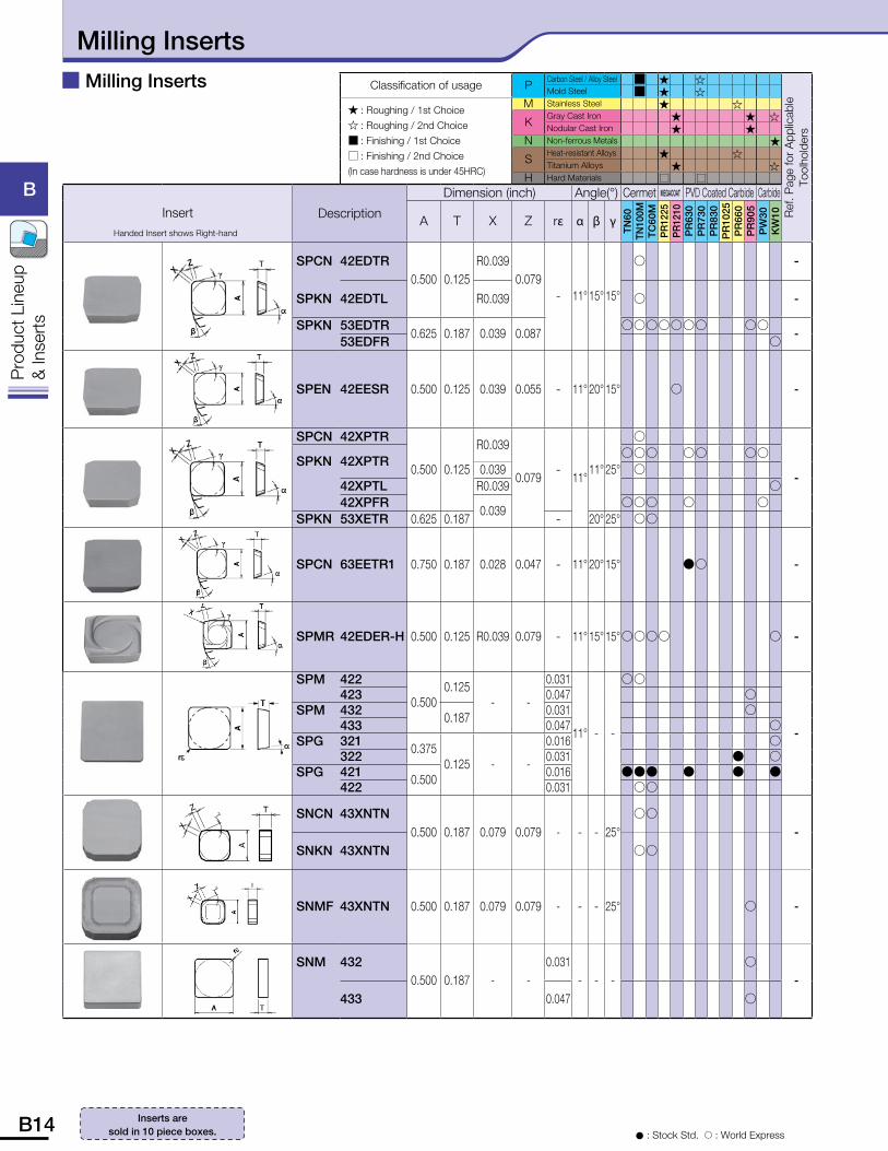
SPCN 42EDTR0.500 0.125
R0.0390.079
- 11° 15° 15°
� -
SPKN 42EDTL R0.039 � -
SPKN 53EDTR0.625 0.187 0.039 0.087
������� �� -
53EDFR �
SPEN 42EESR 0.500 0.125 0.039 0.055 - 11° 20° 15° � -
SPCN 42XPTR
0.500 0.125
R0.039
0.079-
11°11° 25°
�
-SPKN 42XPTR
��� �� �� 0.039 �
42XPTL R0.039 �42XPFR
0.039��� � �
SPKN 53XETR 0.625 0.187 - 20° 25° ��
SPCN 63EETR1 0.750 0.187 0.028 0.047 - 11° 20° 15° �� -
SPMR 42EDER-H 0.500 0.125 R0.039 0.079 - 11° 15° 15°���� � -
SPM 422
0.5000.125
- -
0.031
11° - -
��
-
423 0.047 � SPM 432 0.187 0.031 �
433 0.047 �SPG 321 0.375
0.125 - -
0.016 �322 0.031 � �
SPG 421 0.500 0.016 ��� � � �422 0.031 ��
SNCN 43XNTN0.500 0.187 0.079 0.079 - - - 25°
��
-
SNKN 43XNTN ��
SNMF 43XNTN 0.500 0.187 0.079 0.079 - - - 25° � -
SNM 4320.500 0.187 - -
0.031- - -
�
-
433 0.047 �
Milling Inserts
B14 B15
B
Pro
duct
Lin
eup
& In
sert
s
B
Pro
duct
Lin
eup
& In
sert
s
Classification of usage PCarbon Steel / Alloy Steel � � ���
Ref.
Page
for A
pplic
able
Too
lhol
ders
Mold Steel � � ���
� : Roughing / 1st Choice� : Roughing / 2nd Choice� : Finishing / 1st Choice� : Finishing / 2nd Choice(In case hardness is under 45HRC)
M Stainless Steel � ��
KGray Cast Iron � � �Nodular Cast Iron � �
N Non-ferrous Metals �
SHeat-resistant Alloys � ��Titanium Alloys � �
H Hard Materials � � �
InsertHanded Insert shows Right-hand
Description
Dimension (inch) Angle(°) Cermet MEGACOAT PVD Coated Carbide Carbide
A T X Z r� � � �
TN60
TN10
0MTC
60M
PR
1225
PR
1210
PR
630
PR
730
PR
830
PR
1025
PR
660
PR
905
PW
30K
W10
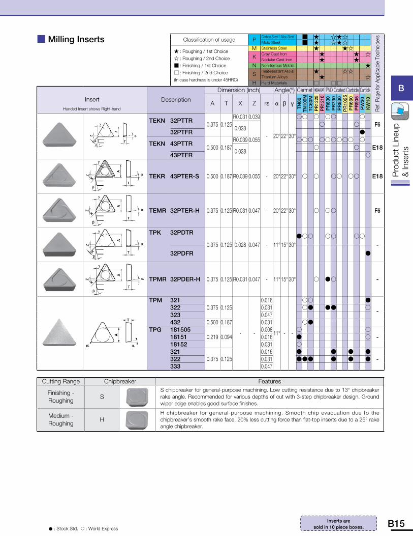
TEKN 32PTTR0.375 0.125
R0.031 0.039
- 20° 22° 30°
�� � �� �F6
0.028
0.055
� �32PTFR �
TEKN 43PTTR0.500 0.187
R0.039 ��� ������ �E18
0.028� �
43PTFR �
TEKR 43PTER-S 0.500 0.187 R0.039 0.055 - 20° 22° 30° � � �� �� E18
TEMR 32PTER-H 0.375 0.125 R0.031 0.047 - 20° 22° 30° � �� F6
TPK 32PDTR
0.375 0.125 0.028 0.047 - 11° 15° 30°��� �� ��
-32PDFR �
TPMR 32PDER-H 0.375 0.125 R0.031 0.047 - 11° 15° 30° � �� -
TPM 3210.375 0.125
- -
0.016
11° - -
�� �
-322 0.031 �� �� �323 0.047 432 0.500 0.187 0.031 ��
TPG 1815050.219 0.094
0.008 � �-18151 0.016 � �
18152 0.031 � 321
0.375 0.1250.016 � � � �
-322 0.031 ��� � � �333 0.047
Cutting Range Chipbreaker Features
Finishing - Roughing
SS chipbreaker for general-purpose machining. Low cutting resistance due to 13° chipbreaker rake angle. Recommended for various depths of cut with 3-step chipbreaker design. Ground wiper edge enables good surface finishes.
Medium - Roughing
HH chipbreaker for general-purpose machining. Smooth chip evacuation due to the chipbreaker’s smooth rake face. 20% less cutting force than flat-top inserts due to a 25° rake angle chipbreaker.
� Milling Inserts
� : Stock Std. � : World Express
Inserts are sold in 10 piece boxes.
B16 B17
B
Pro
duct
Lin
eup
& In
sert
s
B
Pro
duct
Lin
eup
& In
sert
s
Classification of usage PCarbon Steel / Alloy Steel �
Ref
. Pag
e fo
r App
licab
le T
oolh
olde
rs
Mold Steel �
� : Roughing / 1st Choice� : Roughing / 2nd Choice� : Finishing / 1st Choice� : Finishing / 2nd Choice(In case hardness is under 45HRC)
M Stainless Steel �
KGray Cast Iron �Nodular Cast Iron �
N Non-ferrous Metals
SHeat-resistant Alloys �Titanium Alloys �
H Hard Materials �
Insert
Handed Insert shows Right-hand
Description
Dimension (inch) Angle(°)MEGACOAT
NANO
A T ød W Z r� � � �
PR
1525
PR
1510
General Purpose
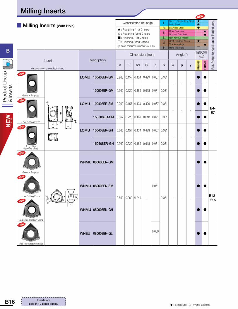
LOMU 100408ER-GM 0.260 0.157 0.134 0.429 0.067 0.031
- - -
� �
E4-E7
150508ER-GM 0.362 0.220 0.189 0.618 0.071 0.031 � �
Low Cutting Force
LOMU 100408ER-SM 0.260 0.157 0.134 0.429 0.067 0.031
- - -
� �
150508ER-SM 0.362 0.220 0.189 0.618 0.071 0.031 � �
Tough Edge (For Heavy Milling)
LOMU 100408ER-GH 0.260 0.157 0.134 0.429 0.067 0.031
- - -
� �
150508ER-GH 0.362 0.220 0.189 0.618 0.071 0.031 � �
General Purpose
WNMU 080608EN-GM
0.552 0.262 0.244 -
0.051
0.031 - - -
� �
E12-E15
Low Cutting Force
WNMU 080608EN-SM � �
Tough Edge (For Heavy Milling)
WNMU 080608EN-GH � �
Surface-Finish Oriented (Precision Class)
WNEU 080608EN-GL0.059
� �
� Milling Inserts (With Hole)
� : Stock Std. � : World Express
Inserts are sold in 10 piece boxes.
Milling Inserts
B16 B17
B
Pro
duct
Lin
eup
& In
sert
s
B
Pro
duct
Lin
eup
& In
sert
s
Classification of usage PCarbon Steel / Alloy Steel � � � ��
Ref.
Page
for A
pplic
able
Too
lhol
ders
Mold Steel � � � ��
� : Roughing / 1st Choice� : Roughing / 2nd Choice� : Finishing / 1st Choice� : Finishing / 2nd Choice(In case hardness is under 45HRC)
M Stainless Steel � � �
KGray Cast Iron � � � �Nodular Cast Iron � � �
N Non-ferrous Metals � �
SHeat-resistant Alloys � � �Titanium Alloys � � �
H Hard Materials � � ��
InsertHanded Insert shows Right-hand
Description
Dimension (inch) Angle(°) MEGACOATNANO Cermet MEGACOAT PVD Coated Carbide Carbide
A T ødW(X)
r�(Z)
� � �
PR
1525
PR
1510
TN10
0MTC
60M
PR
1225
PR
1230
PR
1210
PR
630
PR
730
PR
830
PR
1025
PR
660
PR
905
PW
30K
W10
Wiper Edge
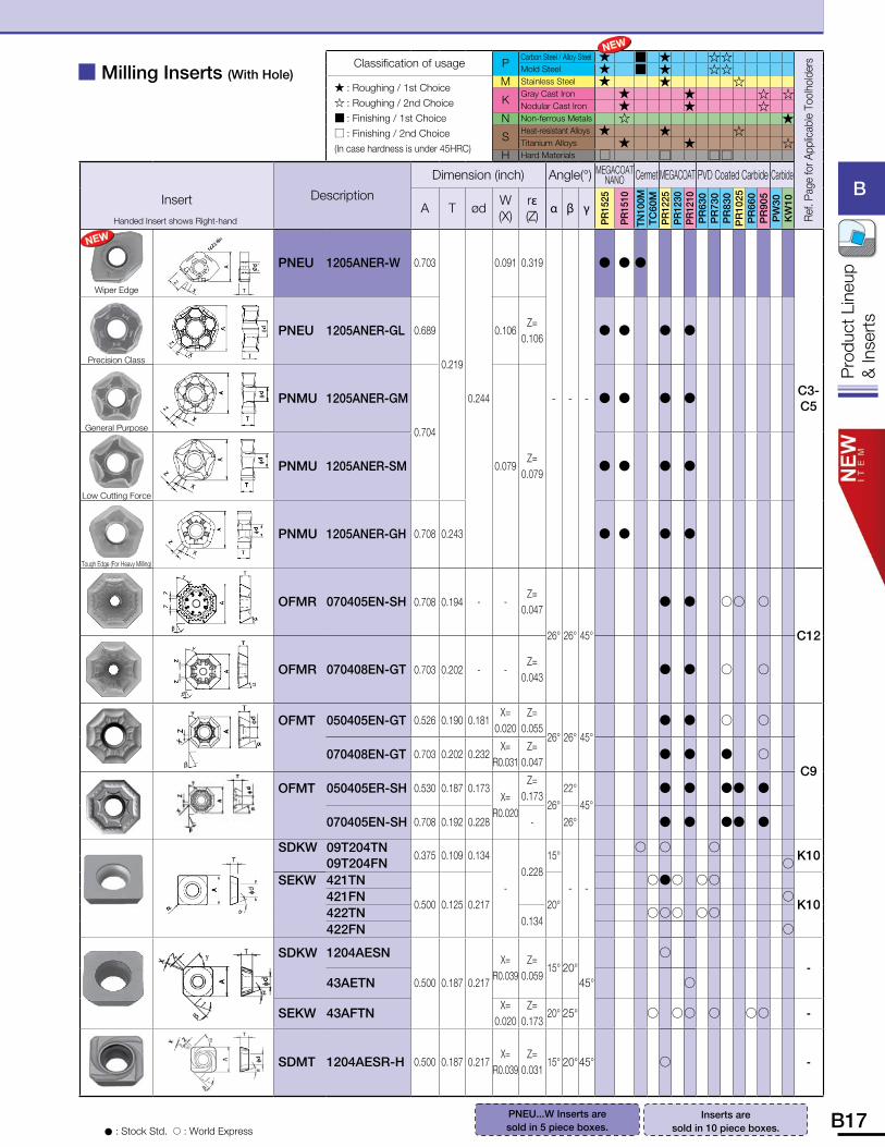
PNEU 1205ANER-W 0.703
0.219
0.244
0.091 0.319
- - -
� � �
C3-C5
Precision Class
PNEU 1205ANER-GL 0.689 0.106Z=
0.106� � � �
General Purpose
PNMU 1205ANER-GM
0.704
0.079Z=
0.079
� � � �
Low Cutting Force
PNMU 1205ANER-SM � � � �
Tough Edge (For Heavy Milling)
PNMU 1205ANER-GH 0.708 0.243 � � � �
OFMR 070405EN-SH 0.708 0.194 - -Z=
0.047
26° 26° 45°
� � �� �
C12
OFMR 070408EN-GT 0.703 0.202 - -Z=
0.043 � � � �
OFMT 050405EN-GT 0.526 0.190 0.181X=
0.020Z=
0.05526° 26° 45°
� � � �
C9070408EN-GT 0.703 0.202 0.232
X=R0.031
Z=0.047
� � � �
OFMT 050405ER-SH 0.530 0.187 0.173X=
R0.020
Z=0.173
26°22°
45° � � �� �
070405EN-SH 0.708 0.192 0.228 - 26° � � �� �
SDKW 09T204TN09T204FN
0.375 0.109 0.134
-0.228
15°
- -
� � � K10
�SEKW 421TN
0.500 0.125 0.217 20°
��� ��
K10421FN �422TN
0.134 ��� ��
422FN �
SDKW 1204AESN
0.500 0.187 0.217
X=R0.039
Z=0.059
15° 20°45°
� -
43AETN �
SEKW 43AFTNX=
0.020Z=
0.17320° 25° � �� � �� -
SDMT 1204AESR-H 0.500 0.187 0.217X=
R0.039Z=
0.03115° 20° 45° � -
� Milling Inserts (With Hole)
� : Stock Std. � : World Express
PNEU...W Inserts are sold in 5 piece boxes.
Inserts are sold in 10 piece boxes.
B18 B19
B
Pro
duct
Lin
eup
& In
sert
s
B
Pro
duct
Lin
eup
& In
sert
s
Classification of usage PCarbon Steel / Alloy Steel � �� ��
Ref.
Page
for A
pplic
able
Too
lhol
ders
Mold Steel � �� ��
� : Roughing / 1st Choice� : Roughing / 2nd Choice� : Finishing / 1st Choice� : Finishing / 2nd Choice(In case hardness is under 45HRC)
M Stainless Steel �� ��
KGray Cast Iron � � �Nodular Cast Iron � �
N Non-ferrous Metals �
SHeat-resistant Alloys �� ��Titanium Alloys � �
H Hard Materials �� ��
Insert
Handed Insert shows Right-hand
Description
Dimension (inch) Angle(°) Cermet MEGACOAT PVD Coated Carbide Carbide
A T ødW(X)
r�(Z)
� � �
TN10
0MTC
60M
PR
1225
PR
1230
PR
1210
PR
630
PR
730
PR
830
PR
1025
PR
660
PR
905
PW
30K
W10
Low Cutting Force
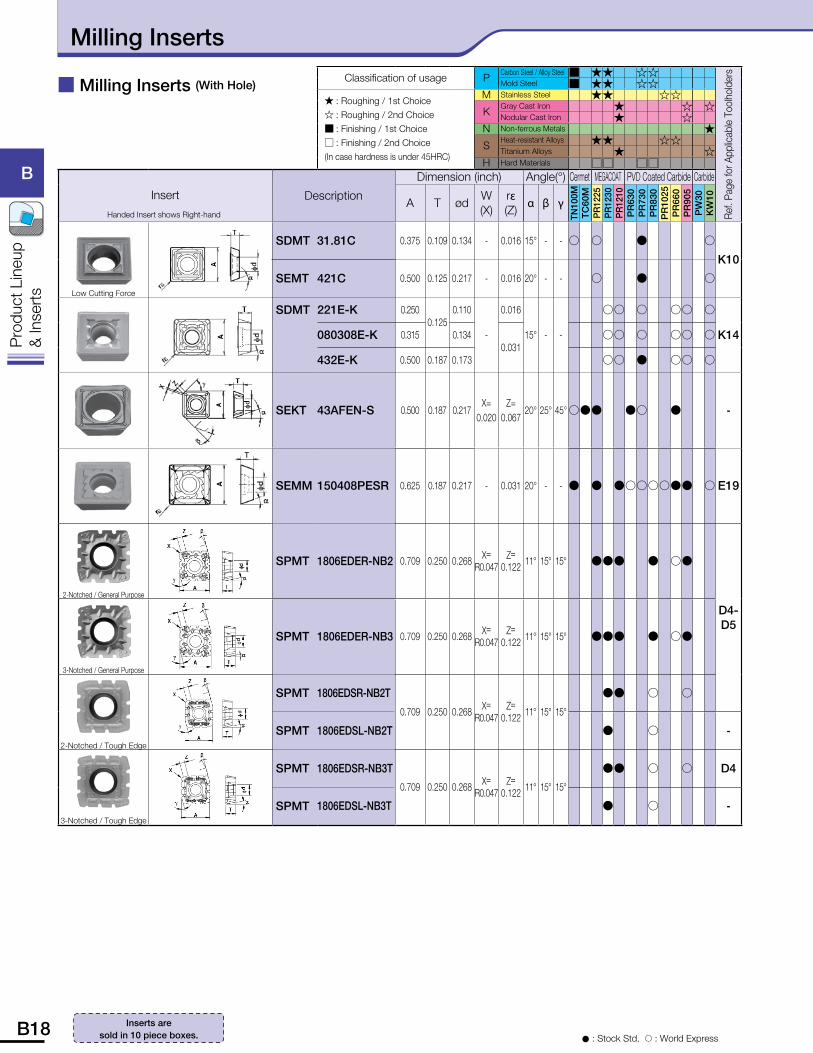
SDMT 31.81C 0.375 0.109 0.134 - 0.016 15° - - � � � �
K10
SEMT 421C 0.500 0.125 0.217 - 0.016 20° - - � � �
SDMT 221E-K 0.2500.125
0.110
-
0.016
15° - -
�� � �� �
K14080308E-K 0.315 0.1340.031
�� � �� �
432E-K 0.500 0.187 0.173 �� � �� �
SEKT 43AFEN-S 0.500 0.187 0.217X=
0.020Z=
0.06720° 25° 45° ��� �� � -
SEMM 150408PESR 0.625 0.187 0.217 - 0.031 20° - - � � ������� � E19
2-Notched / General Purpose
SPMT 1806EDER-NB2 0.709 0.250 0.268 X=R0.047
Z=0.122 11° 15° 15° ��� � ��
D4-D5
3-Notched / General Purpose
SPMT 1806EDER-NB3 0.709 0.250 0.268 X=R0.047
Z=0.122 11° 15° 15° ��� � ��
2-Notched / Tough Edge
SPMT 1806EDSR-NB2T
0.709 0.250 0.268 X=R0.047
Z=0.122 11° 15° 15°
�� � �
SPMT 1806EDSL-NB2T � � -
3-Notched / Tough Edge
SPMT 1806EDSR-NB3T
0.709 0.250 0.268 X=R0.047
Z=0.122 11° 15° 15°
�� � � D4
SPMT 1806EDSL-NB3T � � -
� Milling Inserts (With Hole)
� : Stock Std. � : World Express
Inserts are sold in 10 piece boxes.
Milling Inserts
B18 B19
B
Pro
duct
Lin
eup
& In
sert
s
B
Pro
duct
Lin
eup
& In
sert
s
Classification of usage PCarbon Steel / Alloy Steel �� ��
Ref.
Page
for A
pplic
able
Too
lhol
ders
Mold Steel �� ��
� : Roughing / 1st Choice� : Roughing / 2nd Choice� : Finishing / 1st Choice� : Finishing / 2nd Choice(In case hardness is under 45HRC)
M Stainless Steel �� ��
KGray Cast Iron � � �Nodular Cast Iron � �
N Non-ferrous Metals �
SHeat-resistant Alloys �� ��Titanium Alloys � �
H Hard Materials �� ��
Insert
Handed Insert shows Right-hand
Description
Dimension (inch) Angle(°) Cermet MEGACOAT PVD Coated Carbide Carbide
A T ødW(X)
r�(Z)
� � �
TN10
0MTC
60M
PR
1225
PR
1230
PR
1210
PR
630
PR
730
PR
830
PR
1025
PR
660
PR
905
PW
30K
W10
4-Notched / Low cutting force
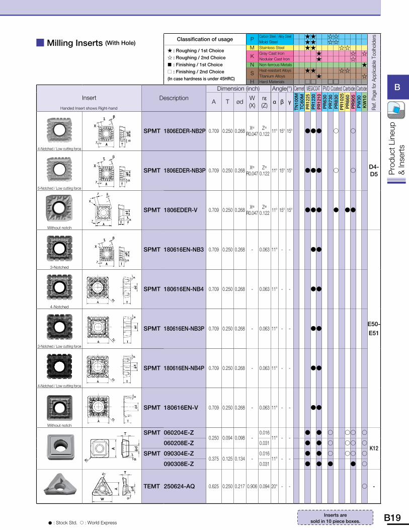
SPMT 1806EDER-NB2P 0.709 0.250 0.268 X=R0.047
Z=0.122 11° 15° 15° ��� � �
D4-D5
5-Notched / Low cutting force
SPMT 1806EDER-NB3P 0.709 0.250 0.268 X=R0.047
Z=0.122 11° 15° 15° ��� � �
Without notch
SPMT 1806EDER-V 0.709 0.250 0.268 X=R0.047
Z=0.122 11° 15° 15° ��� � ��
3-Notched
SPMT 180616EN-NB3 0.709 0.250 0.268 - 0.063 11° - - ��
E50-E51
4-Notched
SPMT 180616EN-NB4 0.709 0.250 0.268 - 0.063 11° - - ��
3-Notched / Low cutting force
SPMT 180616EN-NB3P 0.709 0.250 0.268 - 0.063 11° - - ��
4-Notched / Low cutting force
SPMT 180616EN-NB4P 0.709 0.250 0.268 - 0.063 11° - - ��
Without notch
SPMT 180616EN-V 0.709 0.250 0.268 - 0.063 11° - - ��
SPMT 060204E-Z0.250 0.094 0.098 -
0.01611° - -
� � � �� �
K12060208E-Z 0.031 � � � �� �
SPMT 090304E-Z0.375 0.125 0.134 -
0.01611° - -
� � � �� �
090308E-Z 0.031 � � � � �
TEMT 250624-AQ 0.625 0.250 0.217 0.906 0.094 20° - - � -
� Milling Inserts (With Hole)
� : Stock Std. � : World Express
Inserts are sold in 10 piece boxes.
B20 B21
B
Pro
duct
Lin
eup
& In
sert
s
B
Pro
duct
Lin
eup
& In
sert
s
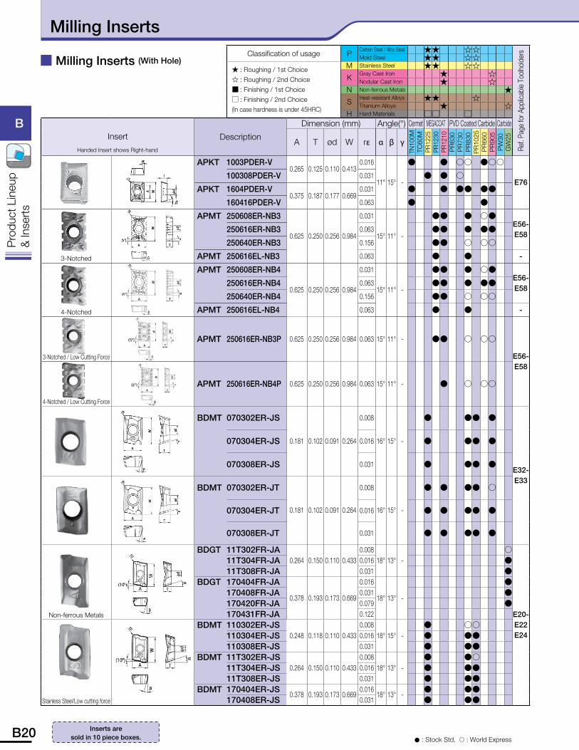
� Milling Inserts (With Hole)
� : Stock Std. � : World Express
Inserts are sold in 10 piece boxes.
Classification of usage PCarbon Steel / Alloy Steel �� ��
Ref.
Page
for A
pplic
able
Tool
hold
ers
Mold Steel �� ��� : Roughing / 1st Choice� : Roughing / 2nd Choice� : Finishing / 1st Choice� : Finishing / 2nd Choice(In case hardness is under 45HRC)
M Stainless Steel �� ��
KGray Cast Iron � �Nodular Cast Iron � �
N Non-ferrous Metals �
SHeat-resistant Alloys �� �Titanium Alloys � �
H Hard Materials �� �
InsertHanded Insert shows Right-hand
Description
Dimension (mm) Angle(°) Cermet MEGACOAT PVD Coated Carbide Carbide
A T ød W r� � � �
TN10
0MTC
60M
PR12
25PR
1230
PR12
10P
R63
0P
R73
0P
R83
0P
R10
25P
R66
0P
R90
5P
W30
GW
25
APKT 1003PDER-V0.265 0.125 0.110 0.413
0.016
11° 15° -
� � �� ���
E76100308PDER-V 0.031 � � �
APKT 1604PDER-V0.375 0.187 0.177 0.669
0.031 � � �� ��
160416PDER-V 0.063 � �
3-Notched
APMT 250608ER-NB3
0.625 0.250 0.256 0.984
0.031
15° 11° -
�� � �� E56-E58
250616ER-NB3 0.063 �� � ��
250640ER-NB3 0.156 �� � ��
APMT 250616EL-NB3 0.063 � � -
4-Notched
APMT 250608ER-NB4
0.625 0.250 0.256 0.984
0.031
15° 11° -
�� � �� E56-E58
250616ER-NB4 0.063 �� � ��
250640ER-NB4 0.156 �� � ��
APMT 250616EL-NB4 0.063 � � -
3-Notched / Low Cutting Force
APMT 250616ER-NB3P 0.625 0.250 0.256 0.984 0.063 15° 11° - �� � ��
E56-E58
4-Notched / Low Cutting Force
APMT 250616ER-NB4P 0.625 0.250 0.256 0.984 0.063 15° 11° - � � ��
BDMT 070302ER-JS
0.181 0.102 0.091 0.264
0.008
16° 15° -
� �� �
E32-E33
070304ER-JS 0.016 � �� �
070308ER-JS 0.031 � �� �
BDMT 070302ER-JT
0.181 0.102 0.091 0.264
0.008
16° 15° -
� � �� �
070304ER-JT 0.016 � � �� �
070308ER-JT 0.031 � � �� �
Non-ferrous Metals
BDGT 11T302FR-JA0.264 0.150 0.110 0.433
0.00818° 13° -
�
E20-E22E24
11T304FR-JA 0.016 �11T308FR-JA 0.031 �
BDGT 170404FR-JA
0.378 0.193 0.173 0.669
0.016
18° 13° -
�170408FR-JA 0.031 �170420FR-JA 0.079 �170431FR-JA 0.122
Stainless Steel/Low cutting force
BDMT 110302ER-JS0.248 0.118 0.110 0.433
0.00818° 15° -
� �� 110304ER-JS 0.016 � �� 110308ER-JS 0.031 � ��
BDMT 11T302ER-JS0.264 0.150 0.110 0.433
0.00818° 13° -
� �� 11T304ER-JS 0.016 � �� 11T308ER-JS 0.031 � ��
BDMT 170404ER-JS0.378 0.193 0.173 0.669
0.01618° 13° -
� �� 170408ER-JS 0.031 � ��
Milling Inserts
B20 B21
B
Pro
duct
Lin
eup
& In
sert
s
B
Pro
duct
Lin
eup
& In
sert
s
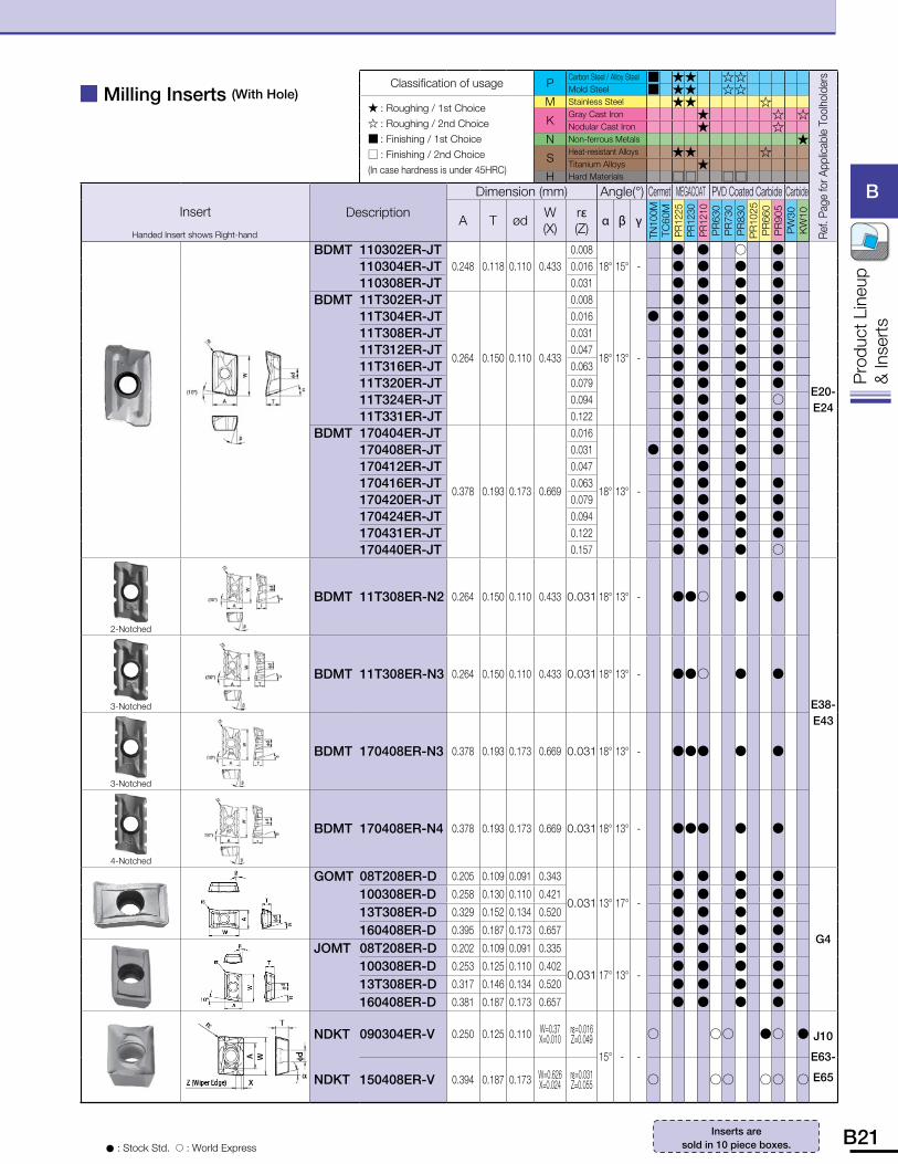
� Milling Inserts (With Hole)
� : Stock Std. � : World Express
Inserts are sold in 10 piece boxes.
Classification of usage PCarbon Steel / Alloy Steel � �� ��
Ref.
Page
for A
pplic
able
Too
lhol
ders
Mold Steel � �� ��
� : Roughing / 1st Choice� : Roughing / 2nd Choice� : Finishing / 1st Choice� : Finishing / 2nd Choice(In case hardness is under 45HRC)
M Stainless Steel �� �
KGray Cast Iron � � �Nodular Cast Iron � �
N Non-ferrous Metals �
SHeat-resistant Alloys �� �Titanium Alloys �
H Hard Materials �� ��
Insert
Handed Insert shows Right-hand
Description
Dimension (mm) Angle(°) Cermet MEGACOAT PVD Coated Carbide Carbide
A T ødW(X)
r�(Z)
� � �
TN10
0MTC
60M
PR12
25PR
1230
PR12
10P
R63
0P
R73
0P
R83
0P
R10
25P
R66
0P
R90
5P
W30
KW
10
BDMT 110302ER-JT0.248 0.118 0.110 0.433
0.00818° 15° -
� � � �
E20-E24
110304ER-JT 0.016 � � � � 110308ER-JT 0.031 � � � �
BDMT 11T302ER-JT
0.264 0.150 0.110 0.433
0.008
18° 13° -
� � � � 11T304ER-JT 0.016 � � � � � 11T308ER-JT 0.031 � � � � 11T312ER-JT 0.047 � � � � 11T316ER-JT 0.063 � � � � 11T320ER-JT 0.079 � � � � 11T324ER-JT 0.094 � � � � 11T331ER-JT 0.122 � � � �
BDMT 170404ER-JT
0.378 0.193 0.173 0.669
0.016
18° 13° -
� � � � 170408ER-JT 0.031 � � � � � 170412ER-JT 0.047 � � � 170416ER-JT 0.063 � � � � 170420ER-JT 0.079 � � � � 170424ER-JT 0.094 � � � � 170431ER-JT 0.122 � � � � 170440ER-JT 0.157 � � � �
2-Notched
BDMT 11T308ER-N2 0.264 0.150 0.110 0.433 0.031 18° 13° - ��� � �
E38-E43
3-Notched
BDMT 11T308ER-N3 0.264 0.150 0.110 0.433 0.031 18° 13° - ��� � �
3-Notched
BDMT 170408ER-N3 0.378 0.193 0.173 0.669 0.031 18° 13° - ��� � �
4-Notched
BDMT 170408ER-N4 0.378 0.193 0.173 0.669 0.031 18° 13° - ��� � �
GOMT 08T208ER-D 0.205 0.109 0.091 0.343
0.031 13° 17° -
� � � �
G4
100308ER-D 0.258 0.130 0.110 0.421 � � � �
13T308ER-D 0.329 0.152 0.134 0.520 � � � �
160408ER-D 0.395 0.187 0.173 0.657 � � � �
JOMT 08T208ER-D 0.202 0.109 0.091 0.335
0.031 17° 13° -
� � � �
100308ER-D 0.253 0.125 0.110 0.402 � � � �
13T308ER-D 0.317 0.146 0.134 0.520 � � � �
160408ER-D 0.381 0.187 0.173 0.657 � � � �
NDKT 090304ER-V 0.250 0.125 0.110 W=0.37X=0.010
r�=0.016Z=0.049
15° - -
� �� �� � J10
E63-
E65NDKT 150408ER-V 0.394 0.187 0.173 W=0.626X=0.024
r�=0.031Z=0.055 � �� �� �
B22 B23
B
Pro
duct
Lin
eup
& In
sert
s
B
Pro
duct
Lin
eup
& In
sert
s
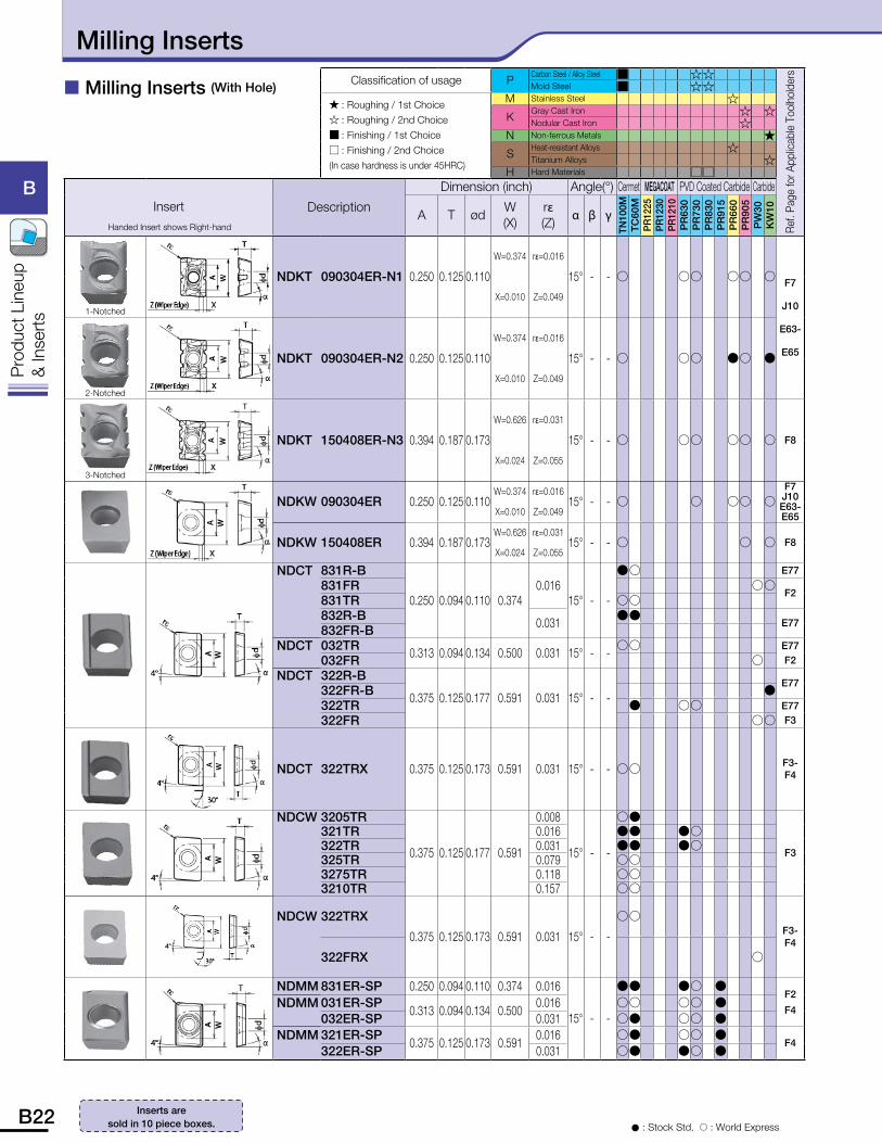
� Milling Inserts (With Hole)
� : Stock Std. � : World Express
Inserts are sold in 10 piece boxes.
Classification of usage PCarbon Steel / Alloy Steel � ��
Ref.
Page
for A
pplic
able
Too
lhol
ders
Mold Steel � ��
� : Roughing / 1st Choice� : Roughing / 2nd Choice� : Finishing / 1st Choice� : Finishing / 2nd Choice(In case hardness is under 45HRC)
M Stainless Steel �
KGray Cast Iron � �Nodular Cast Iron �
N Non-ferrous Metals �
SHeat-resistant Alloys �Titanium Alloys �
H Hard Materials ��
InsertHanded Insert shows Right-hand
Description
Dimension (inch) Angle(°) Cermet MEGACOAT PVD Coated Carbide Carbide
A T ødW(X)
r�(Z)
� � �
TN10
0MTC
60M
PR12
25PR
1230
PR12
10P
R63
0P
R73
0P
R83
0P
R91
5P
R66
0P
R90
5P
W30
KW
10
1-Notched
NDKT 090304ER-N1 0.250 0.125 0.110
W=0.374 r�=0.016
15° - - � �� �� � F7
J10
E63-
E65
X=0.010 Z=0.049
2-Notched
NDKT 090304ER-N2 0.250 0.125 0.110
W=0.374 r�=0.016
15° - - � �� �� �
X=0.010 Z=0.049
3-Notched
NDKT 150408ER-N3 0.394 0.187 0.173
W=0.626 r�=0.031
15° - - � �� �� � F8
X=0.024 Z=0.055
NDKW 090304ER 0.250 0.125 0.110W=0.374 r�=0.016
15° - - � � �� �F7J10E63-E65X=0.010 Z=0.049
NDKW 150408ER 0.394 0.187 0.173W=0.626 r�=0.031
15° - - � � � F8X=0.024 Z=0.055
NDCT 831R-B
0.250 0.094 0.110 0.3740.016
15° - -
�� E77
831FR ��F2
831TR ��832R-B 0.031
��E77
832FR-BNDCT 032TR 0.313 0.094 0.134 0.500 0.031 15° - -
�� E77F2032FR �
NDCT 322R-B
0.375 0.125 0.177 0.591 0.031 15° - -E77
322FR-B �322TR � �� E77
F3322FR ��
NDCT 322TRX 0.375 0.125 0.173 0.591 0.031 15° - - �� F3-F4
NDCW 3205TR
0.375 0.125 0.177 0.591
0.008
15° - -
��
F3
321TR 0.016 �� �� 322TR 0.031 �� �� 325TR 0.079 �� 3275TR 0.118 �� 3210TR 0.157 ��
NDCW 322TRX
0.375 0.125 0.173 0.591 0.031 15° - -
�� F3-F4
322FRX �
NDMM 831ER-SP 0.250 0.094 0.110 0.374 0.016
15° - -
�� �� � F2
F4NDMM 031ER-SP
0.313 0.094 0.134 0.5000.016 �� �� �
032ER-SP 0.031 �� �� � NDMM 321ER-SP
0.375 0.125 0.173 0.5910.016 �� �� �
F4322ER-SP 0.031 �� �� �
Milling Inserts
B22 B23
B
Pro
duct
Lin
eup
& In
sert
s
B
Pro
duct
Lin
eup
& In
sert
s
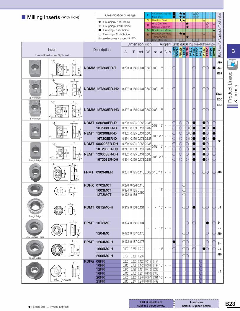
RDFG Inserts are sold in 2 piece boxes.
� Milling Inserts (With Hole)
� : Stock Std. � : World Express
Inserts are sold in 10 piece boxes.
Classification of usage PCarbon Steel / Alloy Steel � �� ��
Ref.
Page
for A
pplic
able
Too
lhol
ders
Mold Steel � �� ��
� : Roughing / 1st Choice� : Roughing / 2nd Choice� : Finishing / 1st Choice� : Finishing / 2nd Choice(In case hardness is under 45HRC)
M Stainless Steel �� �
KGray Cast Iron � � �Nodular Cast Iron � �
N Non-ferrous Metals �
SHeat-resistant Alloys �� �Titanium Alloys � �
H Hard Materials �� ��
InsertHanded Insert shows Right-hand
Description
Dimension (inch) Angle(°) Cermet MEGACOAT PVD Coated Carbide Carbide
A T ød W r� � � �
TN10
0MTC
60M
PR12
25PR
1230
PR12
10P
R63
0P
R73
0P
R83
0P
R91
5P
R66
0P
R90
5P
W30
KW
10
NDMM 12T308ER-T 0.298 0.156 0.134 0.500 0.031 15° - - � � �� �
J10
E63-
E65
2-Notched
NDMM 12T308ER-N2 0.307 0.156 0.134 0.500 0.031 15° - - � � �� �
E63-
E65
E68
3-Notched
NDMM 12T308ER-N3 0.307 0.156 0.134 0.500 0.031 15° - - � � �� �
NDMT 080208ER-D 0.200 0.094 0.087 0.3350.031 15° - -
� � � � �� �
G8
10T208ER-D 0.247 0.109 0.110 0.402 � � ��� �� �
NEMT 120308ER-D 0.302 0.125 0.134 0.5000.031 20° - -
� � ��� �� �
16T308ER-D 0.364 0.156 0.173 0.638 � � ��� �� �
Tough Edge
NDMT 080208ER-DH 0.200 0.094 0.087 0.3350.031 15° - -
� � � � ��
10T208ER-DH 0.247 0.109 0.110 0.402 � � � � �� �
NEMT 120308ER-DH 0.302 0.125 0.134 0.5000.031 20° - -
� � � � �� �
16T308ER-DH 0.364 0.156 0.173 0.638 � � � � �� �
FPMT 090340ER 0.261 0.125 0.110 0.362 0.157 11° - - � �� � J10
RDHX 0702M0T 0.276 0.094 0.110- - 15° - -
� -1003M0T 0.394 0.125
0.150 �
12T3M0T 0.472 0.156 �
Tough Edge
RDMT 08T2M0-H 0.315 0.109 0.134 - - 15° - - �� � �� � J4
Low Cutting Force
RPMT 10T3M0 0.394 0.156 0.134- - 11° - -
� � � � J4-
J5
J101204M0 0.472 0.187 0.173 �� � �
Tough Edge
RPMT 1204M0-H 0.472 0.187 0.173
- - 11° - -
� �� � � J4-
J5
J10
1606M0-H 0.630 0.250 0.217 � �� � �� �
2006M0-H 0.787 0.250 0.256 ��
RDFG 08FR 0.260 0.083 0.122 0.315 0.15715° - -
�
J2
10FR 0.315 0.106 0.142 0.394 0.197 � 12FR 0.370 0.126 0.161 0.472 0.236 � 16FR 0.445 0.165 0.201 0.630 0.315
10° - - �
20FR 0.555 0.205 0.240 0.787 0.394 � 25FR 0.610 0.244 0.240 0.984 0.492 �
B24 B25
B
Pro
duct
Lin
eup
& In
sert
s
B
Pro
duct
Lin
eup
& In
sert
s
� : Stock Std. � : World Express
Classification of usage PCarbon Steel / Alloy Steel � � � �
Ref
. Pag
e fo
r A
pplic
able
Too
lhol
der
Mold Steel � � � �
� : Roughing / 1st Choice� : Roughing / 2nd Choice� : Finishing / 1st Choice� : Finishing / 2nd Choice(In case hardness is under 45HRC)
M Stainless Steel � �
KGray Cast Iron �
Nodular Cast Iron �N Non-ferrous Metals �
SHeat-resistant Alloys � �
Titanium Alloys �H Hard Materials �
Insert
Handed Insert shows Right-hand
Description
Dimension (inch)Angle
(°)
Insert Grade
Cermet CVD
Coat
ed
PVD Coated
Carb
ide
A T Ød W r� � � �
TN10
0M
TC60
20
TC60
CA
2335
PR
660
PR
830
PR
905
PR
930
KW
10
CW
12
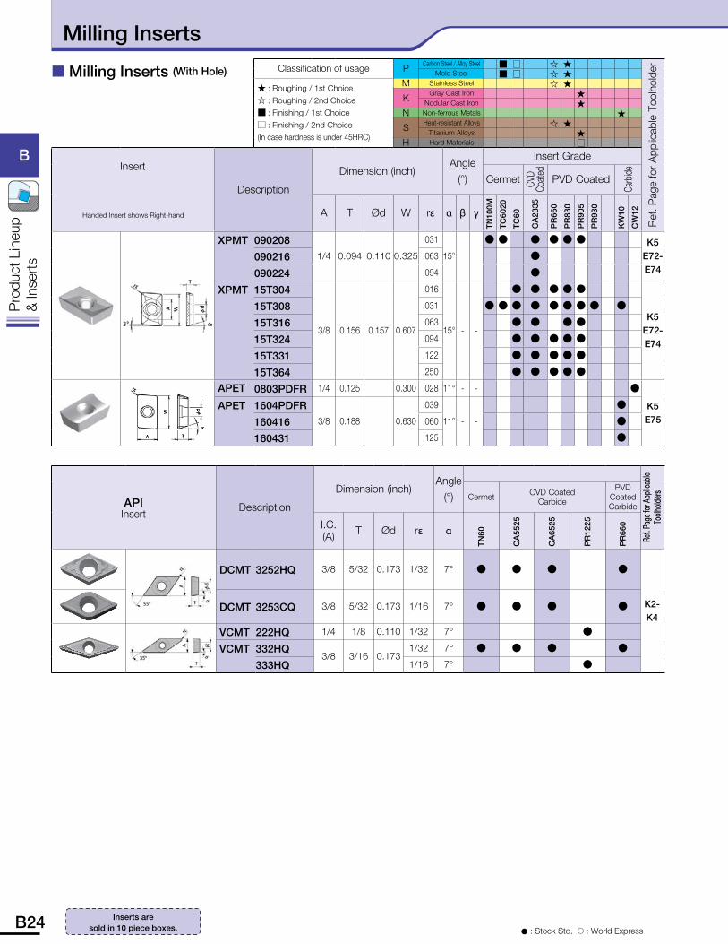
XPMT 0902081/4 0.094 0.110 0.325
.031
15°
� � � � � � K5E72-E74
090216 .063 �
090224 .094 �
XPMT 15T304
3/8 0.156 0.157 0.607
.016
15° - -
� � � � �
K5E72-E74
15T308 .031 � � � � � � � � �
15T316 .063 � � � �
15T324 .094 � � � � �
15T331 .122 � � � � �
15T364 .250 � � � � �
APET 0803PDFR 1/4 0.125 0.300 .028 11° - - �
K5E75
APET 1604PDFR3/8 0.188 0.630
.039
11° - -
�
160416 .060 �
160431 .125 �
APIInsert
Description
Dimension (inch)Angle
(°)
Ref. P
age f
or A
pplic
able
Toolh
oldersCermet CVD Coated
Carbide
PVDCoatedCarbide
I.C.(A) T Ød r� �
TN60
CA
5525
CA
6525
PR
1225
PR
660
DCMT 3252HQ 3/8 5/32 0.173 1/32 7° � � � �
K2-K4
DCMT 3253CQ 3/8 5/32 0.173 1/16 7° � � � �
VCMT 222HQ 1/4 1/8 0.110 1/32 7° �
VCMT 332HQ3/8 3/16 0.173
1/32 7° � � � �
333HQ 1/16 7° �
� Milling Inserts (With Hole)
Inserts are sold in 10 piece boxes.
Milling Inserts
B24 B25
B
Pro
duct
Lin
eup
& In
sert
s
B
Pro
duct
Lin
eup
& In
sert
s
� : Stock Std. � : World Express
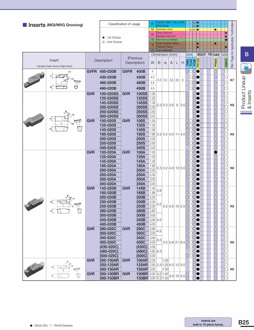
� Inserts (MGI/MVG Grooving)
Inserts are sold in 10 piece boxes.
Classification of usage PCarbon Steel / Alloy Steel � �
Ref.
Page
for A
pplic
able
Too
lhol
ders
Mold Steel � �
� : 1st Choice� : 2nd Choice
M Stainless Steel � � � �
KGray Cast Iron �Nodular Cast Iron �
N Non-ferrous Metals �
SHeat-resistant Alloys � �Titanium Alloys � �
H Hard Materials
InsertHanded Insert shows Right-hand
Description(Previous
Description)
Dimension (mm) Cermet MEGACOAT PVD Coated Carbide
W B r� A L H
TN90
TC40
TC60
PR12
25
PR
660
KW
10
GVFR 400-020B GVFR 400B 4
5.3 0.2 5.8 20 5
���� � �
K7430-020B 430B 4.3 ��� � �
460-020B 460B 4.6 ��� � �
490-020B 490B 4.9 ��� � �
GVR 100-020SS GVR 100SS 1.00
2.3 0.2 3.6 9 3.0
� �� � �
K8
125-020SS 125SS 1.25 � �� � �145-020SS 145SS 1.45 � �� � �200-020SS 200SS 2.00 � �� � �250-020SS 250SS 2.50 � �� � �300-020SS 300SS 3.00 � �� � �
GVR 100-020S GVR 100S 1.00
2.3 0.2 4.0 11 4.0
���� � �
K8
125-020S 125S 1.25 ���� � �145-020S 145S 1.45 ���� � �185-020S 185S 1.85 ���� � �200-020S 200S 2.00 ���� � �250-020S 250S 2.50 ���� � �340-020S 340S 3.40 ��� � �
GVR 100-020A GVR 100A 1.00
2.3 0.2 4.0 12 5.0
���� � �
K8
125-020A 125A 1.25 ���� � �145-020A 145A 1.45 ���� � �185-020A 185A 1.85 ���� � �200-020A 200A 2.00 ���� � �250-020A 250A 2.50 ���� � �300-020A 300A 3.00 ���� � �340-020A 340A 3.40 ���� � �
GVR 145-020B GVR 145B 1.452.8
0.2 4.5 15 5.5
���� � �
K8
185-020B 185B 1.85 ���� � �200-020B 200B 2.00
3.2
���� � �230-020B 230B 2.30 ���� � �250-020B 250B 2.50 ���� � �280-020B 280B 2.80 ���� � �300-020B 300B 3.00
4.2���� � �
340-020B 340B 3.40 ���� � �400-020B 400B 4.00 ���� � �
GVR 280-020C GVR 280C 2.804.5
0.2 5.8 21 6.5
���� � �
K8
300-020C 300C 3.00 ���� � �340-020C 340C 3.40
5.5���� � �
400-020C 400C 4.00 ���� � �(430-020C) (430C) 4.30
6.3���� � �
(460-020C) (460C) 4.60 ��� � �(500-020C) (500C) 5.00 ���� � �
GVR 200-100AR GVR 100AR 2.002.3
1.004.0 12 5.0
�� � �
K8250-125AR 125AR 2.50 1.25 �� � �300-150AR 150AR 3.00 1.50 �� � �
GVR 200-100BR GVR 100BR 2.00 3.2 1.004.5 15 5.5
� �� � �300-150BR 150BR 3.00 4.2 1.50 � �� � �
B26 B27
B
Pro
duct
Lin
eup
& In
sert
s
B
Pro
duct
Lin
eup
& In
sert
s
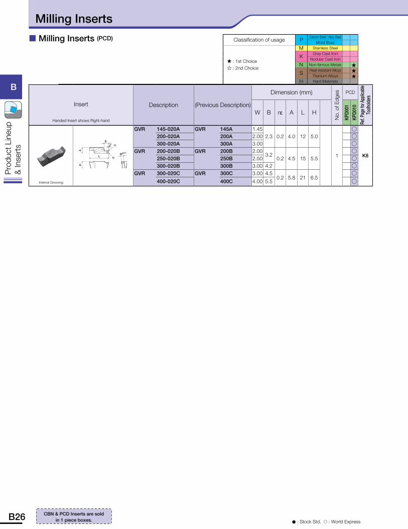
� Milling Inserts (PCD)
Insert
Handed Insert shows Right-hand
Description (Previous Description)
Dimension (mm)
No.
of E
dges PCD
Ref. P
age f
or A
pplic
able
Toolh
olders
W B r� A L H
KPD0
01KP
D010
Internal Grooving
GVR 145-020A GVR 145A 1.452.3 0.2 4.0 12 5.0
1
�
K8
200-020A 200A 2.00 �300-020A 300A 3.00 �
GVR 200-020B GVR 200B 2.003.2
0.2 4.5 15 5.5�
250-020B 250B 2.50 �300-020B 300B 3.00 4.2 �
GVR 300-020C GVR 300C 3.00 4.50.2 5.8 21 6.5
�400-020C 400C 4.00 5.5 �
� : Stock Std. � : World Express
CBN & PCD Inserts are sold in 1 piece boxes.
Classification of usage PCarbon Steel / Alloy Steel
Mold Steel
� : 1st Choice� : 2nd Choice
M Stainless Steel
KGray Cast Iron
Nodular Cast Iron
N Non-ferrous Metals �
SHeat-resistant Alloys �
Titanium Alloys �H Hard Materials
Milling Inserts
B26 B27
B
Pro
duct
Lin
eup
& In
sert
s
B
Pro
duct
Lin
eup
& In
sert
s
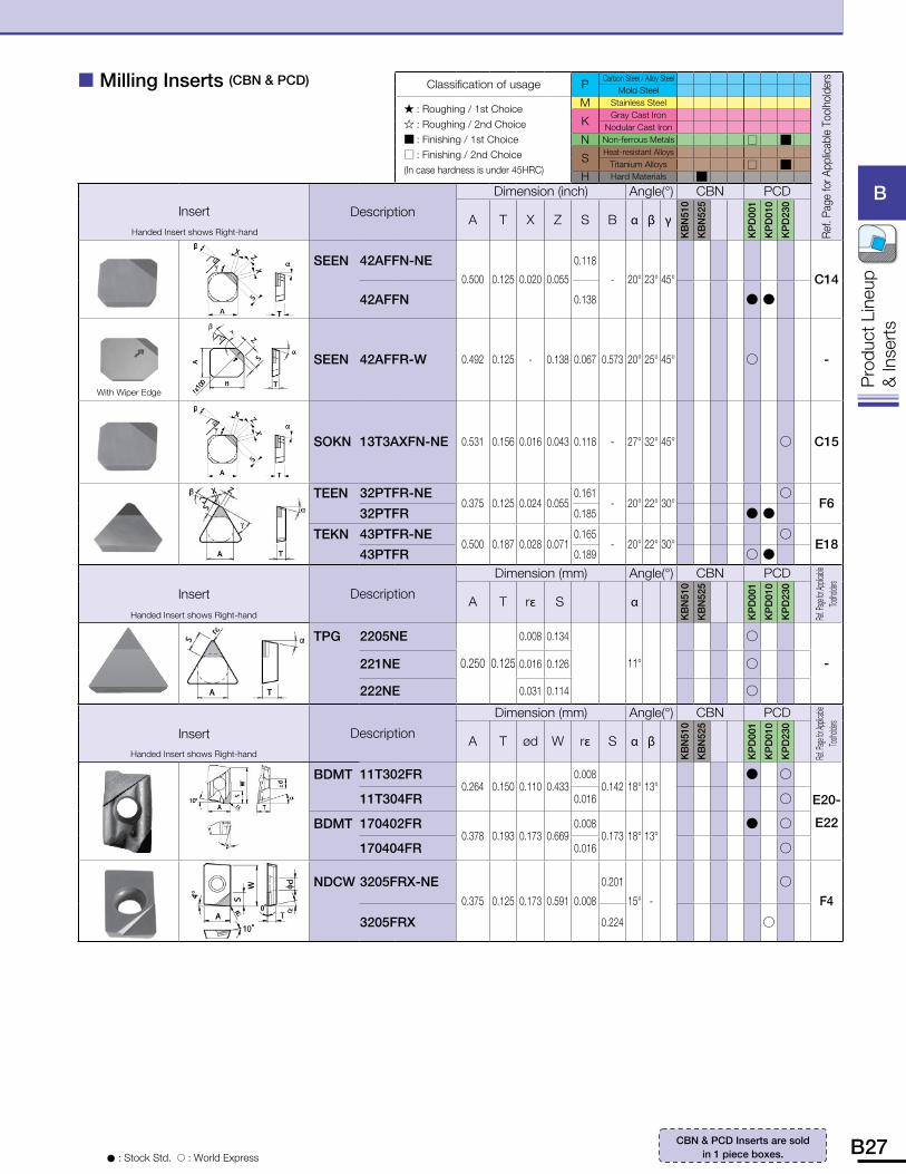
� Milling Inserts (CBN & PCD)
� : Stock Std. � : World Express
CBN & PCD Inserts are sold in 1 piece boxes.
Classification of usage PCarbon Steel / Alloy Steel
Ref.
Page
for A
pplic
able
Too
lhol
ders
Mold Steel
� : Roughing / 1st Choice� : Roughing / 2nd Choice� : Finishing / 1st Choice� : Finishing / 2nd Choice(In case hardness is under 45HRC)
M Stainless Steel
KGray Cast Iron
Nodular Cast Iron
N Non-ferrous Metals � �
SHeat-resistant Alloys
Titanium Alloys � �H Hard Materials �
InsertHanded Insert shows Right-hand
Description
Dimension (inch) Angle(°) CBN PCD
A T X Z S B � � �
KB
N51
0
KB
N52
5
KP
D00
1
KP
D01
0
KP
D23
0
SEEN 42AFFN-NE0.500 0.125 0.020 0.055
0.118
- 20° 23° 45°
C14
42AFFN 0.138 � �
With Wiper Edge
SEEN 42AFFR-W 0.492 0.125 - 0.138 0.067 0.573 20° 25° 45° � -
SOKN 13T3AXFN-NE 0.531 0.156 0.016 0.043 0.118 - 27° 32° 45° � C15
TEEN 32PTFR-NE0.375 0.125 0.024 0.055
0.161- 20° 22° 30°
�F6
32PTFR 0.185 � �
TEKN 43PTFR-NE0.500 0.187 0.028 0.071
0.165- 20° 22° 30°
�E18
43PTFR 0.189 � �
InsertHanded Insert shows Right-hand
Description
Dimension (mm) Angle(°) CBN PCD
Ref. Pa
ge for
Applica
ble
Toolho
lders
A T r� S �
KB
N51
0
KB
N52
5
KP
D00
1
KP
D01
0
KP
D23
0
TPG 2205NE
0.250 0.125
0.008 0.134
11°
�
-221NE 0.016 0.126 �
222NE 0.031 0.114 �
InsertHanded Insert shows Right-hand
Description
Dimension (mm) Angle(°) CBN PCD
Ref. Pa
ge for
Applica
ble
Toolho
lders
A T ød W r� S � �
KB
N51
0
KB
N52
5
KP
D00
1
KP
D01
0
KP
D23
0BDMT 11T302FR
0.264 0.150 0.110 0.4330.008
0.142 18° 13° � �
E20-
E22
11T304FR 0.016 �
BDMT 170402FR0.378 0.193 0.173 0.669
0.0080.173 18° 13°
� �
170404FR 0.016 �
NDCW 3205FRX-NE0.375 0.125 0.173 0.591 0.008
0.201
15° -
�
F4
3205FRX 0.224 �


![[Product Monograph Template - Standard]€¦ · PRODUCT MONOGRAPH PrVagifem® 10 Estradiol vaginal inserts USP, 10 µg estradiol Vaginal inserts with applicators Estrogen Novo Nordisk](https://img.pdfslide.us/doc/110x75/5b53a0e67f8b9ae30b8c320e/product-monograph-template-standard-product-monograph-prvagifem-10-estradiol.jpg)