Embed Size (px)
Citation preview

Product information
www.DrakaMOG.com
Marine, Oil & Gas

DRAKA Product information MOG 2010

For more than 100 years, Draka has met and exceeded challenging marine and offshore demands for electrical and data solutions. As a leading provider of cabling solutions, we are backed by quality manufacturing and local inventory in every key marine and offshore market. By focusing on customer needs, Draka employees deliver trusted, timely and dependable service for ships, oil rigs, subsea and offshore wind farms.
We take pleasure in presenting this catalog with our Shipboard cables.
The ShipLine Plus range is our standard range suitable for all ships including dredging vessels, marine vessels and FPSO’s.The cables have an innersheet and circular non-compacted conductors for increased flexibility and ease of installation.
For applications in less harsh environment like yachts and cruise vessels, we have the ShipLine range. This range is lighter and more compact.
For use in emergency systems where Fire Resistant cables (IEC 60331) is needed, we have our ShipLine FR cables available from stock.
In addition to these ranges we supply an extensive range of data cables, medium voltage cables, offshore cables and special cables.
You will find members of the Draka team working all around the globe, with strong presence in your home market. They represent literally hundreds of years of experience with product development, quality management and on-time project delivery. This unique expertise and understanding of the market enables Draka to provide you with the services you need to meet your toughest marine and offshore challenge.
Please visit www.DrakaMOG.com to learn more about what Draka can do to help you and for more the most recent information about our products.
Yours sincerely,
Draka
ShipLine Plus•halogen-free•internationalstandards•circularconductors•easytoinstall
ShipLine•halogen-free•internationalstandards•light-weight•cost-saving
ShipLine Fire Resistant•halogen-free•internationalstandards•fireresistant
Draka ShipLine range; the choice for reliability and flexibility
3DRAKA Product information MOG 2010

Sheath colours
Power black
Instrument/signal grey
Fire resistant green
Standards applied
IEC 60092-3 Electrical installations in ships – Construction, testing and installation
IEC 60092-350 Low voltage shipboard power cables
IEC 60092-351 Insulating materials for shipboard power cables
IEC 60092-353 Single and multicore cables with extruded solid insulation for rated voltages 0.6/ 1 kV
IEC 60092-359 Sheating materials for shipboard power and telecommunication cables
IEC 60092-375 Shipboard telecommunication cables and radio frequency cables General instrumentation, control and communication cables
IEC 60092-376 Shipboard multicore cables for control circuits
IEC 60331 Tests for electric cables under fire conditions – Circuit integrity
IEC 60332-1 Tests on electric cables under fire conditions – Single vertical insulated wire or cable
IEC 60332-3A Tests on electric cables under fire conditions – Vertical flame spread of vertically mounted bunched wires and cables, category A
IEC 60754-1,2 Tests on gases evolved during combustion of materials from cables Determination of the amount of halogen acid gas Determination of degree of acidity by measuring Ph and conductivity
IEC 61034-1,2 Measurement of smoke density of cables burning under defined conditions Test apparatus, test procedures and requirements
Core identification
1 core black
2 cores blue – brown
3 cores brown – black – grey
4 cores blue - brown – black – grey
5 cores blue - brown – black – grey – black
6 cores and above white with black numbers
Earth core yellow/ green (optional)
Approvals
American Bureau of Shipping
Bureau Veritas
Det Norske Veritas
Germanischer Lloyd
Lloyd’s Register of Shipping
Certification by other classification bureaus at request.
4 DRAKA Product information MOG 2010

For more information about these cables please visit www.DrakaMOG.com
Index
ShipLine Plus Page
TFXI 0.6/1 kV (HUSK) Power cable, unarmoured 6
TIOI 0.6/1 kV (HUSO) Power cable, armoured 8
TIOI (c) 250 V (HUCOM) Instrumentation cable, screened 11
ShipLine
TI 0.6/1 kV Power cable, unarmoured 12
TXOI 0.6/1 kV Power cable, armoured 14
TXOI 250 V Instrumentation cable, screened 16
ShipLine Fire Resistant
BI FR 0.6/1 kV Power cable, Fire Resistant, unarmoured 17
BXOI FR 0.6/1 kV Power cable, Fire Resistant, armoured 18
BXOI FR 250 V Instrumentation cable, Fire resistant, screened 19
Data cables
Overview Data, FR, Video/Audio, CATV 20
Electrical characteristics of cables 21
Also available on request
Offshore cables
RFOU (NEK606) LV, MV, instrumentation (Mud resistant)
BFOU (NEK606) LV, MV, instrumentation (Fire/Mud resistant)
RFCU (UKOOA) LV, MV, instrumentation (Mud resistant)
BFCU (UKOOA) LV, MV, instrumentation (Fire/Mud resistant)
Type P (IEEE45) LV, MV, instrumentation (Mud resistant)
HXXM (IEEE45/IEC) LV, MV, instrumentation (Fire resistant)
Special cables
Flexible EMC Dredging cable 0,6/1 kV and 1,8/3,6 kV
NEK606 HCF 1100C
NEK606 Artic Grade (Cold bend/Cold impact)
TFOI 6/10 kV (also other Voltage rates on request)
Down hole Pump cable
VFD cables
Hulto EMC
ShipLine Plus Fire Resistant
BFXI 0.6/1 kV (HUSK FR) Power cable, Fire Resistant, not braided
BIOI 0.6/1 kV (HUSO FR) Power cable, Fire Resistant, braided
BIOI 250 V (HUCOM FR) Instrumentation cable, Fire resistant, braided
5DRAKA Product information MOG 2010
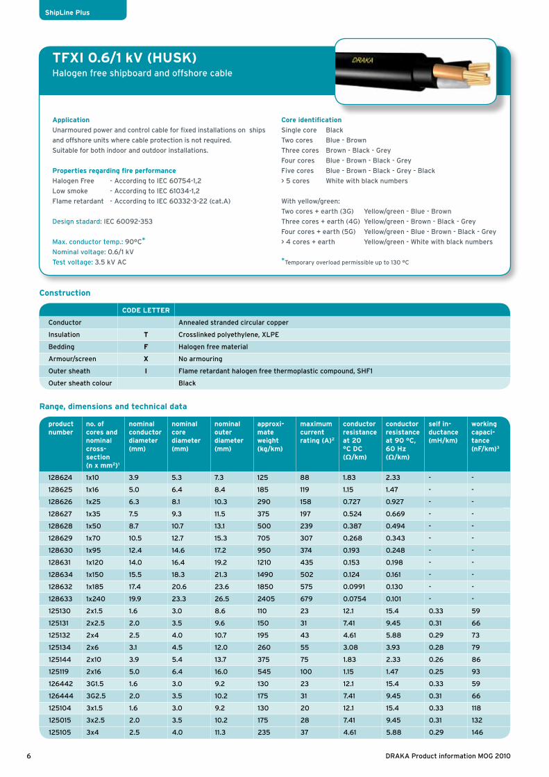
TFXI 0.6/1 kV (HUSK)Halogen free shipboard and offshore cable
Application
Unarmoured power and control cable for fixed installations on ships
and offshore units where cable protection is not required.
Suitable for both indoor and outdoor installations.
Properties regarding fire performance
Halogen Free - According to IEC 60754-1,2
Low smoke - According to IEC 61034-1,2
Flame retardant - According to IEC 60332-3-22 (cat.A)
Design stadard: IEC 60092-353
Max. conductor temp.: 90°C*
Nominal voltage: 0.6/1 kV
Test voltage: 3.5 kV AC
Core identification
Single core Black
Two cores Blue - Brown
Three cores Brown - Black - Grey
Four cores Blue - Brown - Black - Grey
Five cores Blue - Brown - Black - Grey - Black
> 5 cores White with black numbers
With yellow/green:
Two cores + earth (3G) Yellow/green - Blue - Brown
Three cores + earth (4G) Yellow/green - Brown - Black - Grey
Four cores + earth (5G) Yellow/green - Blue - Brown - Black - Grey
> 4 cores + earth Yellow/green - White with black numbers
*Temporary overload permissible up to 130 °C
CODE LETTER
Conductor Annealed stranded circular copper
Insulation T Crosslinked polyethylene, XLPE
Bedding F Halogen free material
Armour/screen X No armouring
Outer sheath I Flame retardant halogen free thermoplastic compound, SHF1
Outer sheath colour Black
Construction
Range, dimensions and technical data
product number
no. of cores and nominal cross- section (n x mm2)1
nominal conductor diameter (mm)
nominal core diameter (mm)
nominal outer diameter (mm)
approxi- mate weight (kg/km)
maximum current rating (A)2
conductor resistance at 20 °C DC (Ω/km)
conductor resistance at 90 °C, 60 Hz (Ω/km)
self in-ductance (mH/km)
working capaci-tance (nF/km)3
128624 1x10 3.9 5.3 7.3 125 88 1.83 2.33 - -
128625 1x16 5.0 6.4 8.4 185 119 1.15 1.47 - -
128626 1x25 6.3 8.1 10.3 290 158 0.727 0.927 - -
128627 1x35 7.5 9.3 11.5 375 197 0.524 0.669 - -
128628 1x50 8.7 10.7 13.1 500 239 0.387 0.494 - -
128629 1x70 10.5 12.7 15.3 705 307 0.268 0.343 - -
128630 1x95 12.4 14.6 17.2 950 374 0.193 0.248 - -
128631 1x120 14.0 16.4 19.2 1210 435 0.153 0.198 - -
128634 1x150 15.5 18.3 21.3 1490 502 0.124 0.161 - -
128632 1x185 17.4 20.6 23.6 1850 575 0.0991 0.130 - -
128633 1x240 19.9 23.3 26.5 2405 679 0.0754 0.101 - -
125130 2x1.5 1.6 3.0 8.6 110 23 12.1 15.4 0.33 59
125131 2x2.5 2.0 3.5 9.6 150 31 7.41 9.45 0.31 66
125132 2x4 2.5 4.0 10.7 195 43 4.61 5.88 0.29 73
125134 2x6 3.1 4.5 12.0 260 55 3.08 3.93 0.28 79
125144 2x10 3.9 5.4 13.7 375 75 1.83 2.33 0.26 86
125119 2x16 5.0 6.4 16.0 545 100 1.15 1.47 0.25 93
126442 3G1.5 1.6 3.0 9.2 130 23 12.1 15.4 0.33 59
126444 3G2.5 2.0 3.5 10.2 175 31 7.41 9.45 0.31 66
125104 3x1.5 1.6 3.0 9.2 130 20 12.1 15.4 0.33 118
125015 3x2.5 2.0 3.5 10.2 175 28 7.41 9.45 0.31 132
125105 3x4 2.5 4.0 11.3 235 37 4.61 5.88 0.29 146
6 DRAKA Product information MOG 2010
ShipLine Plus

Range, dimensions and technical data
Installation recommendations
Minimum bending radius during installation
Minimum bending radius fixed installed
Maximum tensile load during installation
Minimum installation temperature
8 x D 6 x D 50 N * total cross section conductors -20 °C
TFXI 0.6/1 kV (HUSK)Halogen free shipboard and offshore cable
Other cross-sections and numbers of cores are available on request.
1 G = including green/yellow2 The current rating is based on an ambient temperature of 45 °C and a
maximum operating temperature of 90 °C, according to IEC 60092-
352 Table A.4:
I. For singel core cables, Method G: 3 cores spaced in free air
II. For multi-core cables, Method E: Multi-core cables in free air
- For 3G core cables, the values for 2 loaded cores are given.
- For 4 en 5 core cables, the values for 3 loaded cores are given.
Correction factors for different ambient temperatures are
given on page 21.3 Working capacitance for one-phase asymmetrical or three-phase
symmetrical system. The working capacitance of multicore types n>5
depends on the way the wires are connected.
product number
no. of cores and nominal cross- section (n x mm2)1
nominal conductor diameter (mm)
nominal core diameter (mm)
nominal outer diameter (mm)
approxi- mate weight (kg/km)
maximum current rating (A)2
conductor resistance at 20 °C DC (Ω/km)
conductor resistance at 90 °C, 60 Hz (Ω/km)
self in-ductance (mH/km)
working capaci-tance (nF/km)3
125106 3x6 3.1 4.5 12.7 315 47 3.08 3.93 0.28 158
125107 3x10 3.9 5.4 14.7 470 65 1.83 2.33 0.26 172
125109 3x16 5.0 6.4 17.0 680 87 1.15 1.47 0.25 186
125088 3x25 6.3 8.1 21.1 1060 110 0.727 0.927 0.25 199
125110 3x35 7.5 9.4 23.9 1390 137 0.524 0.669 0.24 208
125089 3x50 8.7 10.8 28.3 1925 167 0.387 0.494 0.24 218
124994 3x70 10.5 12.8 33.1 2710 214 0.268 0.343 0.23 228
125090 3x95 12.4 14.7 37.8 3670 259 0.193 0.248 0.22 237
125112 3x120 14.0 16.5 42.0 4600 301 0.153 0.198 0.22 244
125111 3x150 15.5 18.4 46.3 5625 347 0.124 0.161 0.22 250
126443 4G1.5 1.6 3.0 10.0 155 20 12.1 15.4 0.35 135
126445 4G2.5 2.0 3.5 11.1 205 28 7.41 9.45 0.33 150
126446 4G6 3.1 4.5 13.9 385 47 3.08 3.93 0.30 176
125135 4x1.5 1.6 3.0 10.0 155 20 12.1 15.4 0.35 135
125140 4x2.5 2.0 3.5 11.1 205 28 7.41 9.45 0.33 150
125141 4x4 2.5 4.0 12.6 290 37 4.61 5.88 0.31 164
125143 4x6 3.1 4.5 13.9 385 47 3.08 3.93 0.30 176
125145 4x10 3.9 5.4 16.1 580 65 1.83 2.33 0.29 192
125146 4x16 5.0 6.4 18.9 860 87 1.15 1.47 0.28 206
127385 5G1.5 1.6 3.0 10.9 185 20 12.1 15.4 - 140
127386 5G2.5 2.0 3.5 12.3 250 28 7.41 9.45 - 155
125441 5x1.5 1.6 3.0 10.9 185 20 12.1 15.4 - 140
125440 5x2.5 2.0 3.5 12.3 250 28 7.41 9.45 - 155
128639 6x1.5 1.6 3.0 11.4 175 15 12.1 15.4 - ≤155
128640 7x1.5 1.6 3.0 11.5 185 14 12.1 15.4 - ≤155
128647 8G1.5 1.6 3.0 12.7 220 14 12.1 15.4 - ≤155
128641 8x1.5 1.6 3.0 12.7 220 13 12.1 15.4 - ≤155
128642 10x1.5 1.6 3.0 14.6 265 12 12.1 15.4 - ≤155
128643 12x1.5 1.6 3.0 15.3 315 11 12.1 15.4 - ≤155
128644 16x1.5 1.6 3.0 17.0 400 10 12.1 15.4 - ≤155
128645 19x1.5 1.6 3.0 18.1 470 9 12.1 15.4 - ≤155
128646 24x1.5 1.6 3.0 21.3 620 8 12.1 15.4 - ≤155
7DRAKA Product information MOG 2010
ShipLine Plus

TIOI 0.6/1 kV (HUSO)Armoured halogen free shipboard and offshore cable
Application
Armoured power-, control- and lighting cable for fixed installations
on ships and offshore units where cable protection is required.
Suitable for both indoor and outdoor installations.
Properties regarding fire performance
Halogen Free - According to IEC 60754-1,2
Low smoke - According to IEC 61034-1,2
Flame retardant - According to IEC 60332-3-22 (cat.A)
Design standard: IEC 60092-353
Max. conductor temp.: 90°C*
Nominal voltage: 0.6/1 kV
Test voltage: 3.5 kV AC
Core identification
Single core Black
Two cores Blue - Brown
Three cores Brown - Black - Grey
Four cores Blue - Brown - Black - Grey
Five cores Blue - Brown - Black - Grey - Black
> 5 cores White with black numbers
With yellow/green.
Two cores + earth (3G) Yellow/green - Blue - Brown
Three cores + earth (4G) Yellow/green - Brown - Black - Grey
Four cores + earth (5G) Yellow/green - Blue - Brown - Black - Grey
*Temporary overload permissible up to 130 °C
CODE LETTER
Conductor Annealed stranded circular copper
Insulation T Crosslinked polyethylene, XLPE
Inner sheath I Flame retardant halogen free thermoplastic compound, SHF1
Armour/screen O Tinned copper wire braiding
Outer sheath I Flame retardant halogen free thermoplastic compound, SHF1
Outer sheath colour Black
Construction
Range, dimensions and technical data
pro
du
ct
nu
mber
no.
of
core
s an
d n
om
inal
cros
s-se
ctio
n
(n x
mm
2)1
nom
inal cr
oss-
sect
ion
al are
a
of t
he
eart
h
lead (
mm
2)
nom
inal
con
du
ctor
dia
met
er
(mm
)
nom
inal
core
dia
met
er
(mm
)
nom
inal
ou
ter
dia
met
er
(mm
)
appro
xim
ate
w
eight
(k
g/k
m)
maxim
um
cu
rren
t
rati
ng
(A)2
con
du
ctor
resi
stan
ce
at
20
°C
DC
(Ω
/km
)
con
du
ctor
resi
stan
ce a
t 9
0 °
C, 6
0 H
z
(Ω/k
m)
self
in
du
ctan
ce
(mH
/km
)
work
ing
capaci
tan
ce
(nF/
km)3
125043 1x10 2.5 3.9 5.4 10.0 210 88 1.83 2.33 - -
125044 1x16 2.5 5.0 6.4 11.0 280 119 1.15 1.47 - -
125047 1x25 4 6.3 8.1 13.1 410 158 0.727 0.927 - -
125048 1x35 6 7.5 9.4 14.8 545 197 0.524 0.669 - -
125050 1x50 6 8.7 10.8 16.4 690 239 0.387 0.494 - -
125058 1x70 6 10.5 12.8 18.8 935 307 0.268 0.343 - -
125059 1x95 10 12.4 14.7 20.7 1205 374 0.193 0.248 - -
125051 1x120 10 14.0 16.5 22.9 1500 435 0.153 0.198 - -
125053 1x150 16 15.5 18.4 25.0 1810 502 0.124 0.162 - -
125055 1x185 16 17.4 20.7 27.6 2225 575 0.0991 0.131 - -
125056 1x240 16 19.9 23.4 30.5 2825 679 0.0754 0.102 - -
127296 1x300 25 22.3 26.0 34.0 3540 785 0.0601 0.0831 - -
125061 2x1.5 4 1.6 3.0 11.3 205 23 12.1 15.4 0.36 99
125078 2x2.5 4 2.0 3.5 12.4 255 31 7.41 9.45 0.34 118
125080 2x4 6 2.5 4.0 13.9 345 43 4.61 5.88 0.32 135
127302 2x6 6 3.1 4.5 15.2 430 55 3.08 3.93 0.30 150
125034 2x10 10 3.9 5.4 17.0 570 75 1.83 2.33 0.29 169
125035 2x16 16 5.0 6.4 19.8 815 100 1.15 1.47 0.27 186
127321 2x25 16 6.3 8.1 23.2 1135 130 0.727 0.927 0.27 203
127328 2x35 16 7.5 9.4 26.0 1415 161 0.524 0.669 0.25 215
127379 3G1.5 4 1.6 3.0 12.0 235 23 12.1 15.4 0.36 60
8 DRAKA Product information MOG 2010
ShipLine Plus

TIOI 0.6/1 kV (HUSO)Armoured halogen free shipboard and offshore cable
Range, dimensions and technical data
pro
du
ct
nu
mber
no.
of
core
s an
d n
om
inal
cros
s-se
ctio
n
(n x
mm
2)1
nom
inal cr
oss-
sect
ion
al are
a
of t
he
eart
h
lead (
mm
2)
nom
inal
con
du
ctor
dia
met
er (
mm
)
nom
inal
core
dia
met
er
(mm
)
nom
inal
ou
ter
dia
met
er
(mm
)
appro
xim
ate
w
eight
(k
g/k
m)
maxim
um
cu
rren
t
rati
ng
(A)2
con
du
ctor
resi
stan
ce
at
20
°C
DC
(Ω
/km
)
con
du
ctor
resi
stan
ce a
t 9
0 °
C, 6
0 H
z
(Ω/k
m)
self
in
du
c tan
ce
(mH
/km
)
work
ing
capaci
tan
ce
(nF/
km)3
127380 3G2.5 4 2.0 3.5 13.0 290 31 7.4 19.45 0.34 70
125020 3x1.5 4 1.6 3.0 12.0 235 20 2.1 15.4 0.36 121
125016 3x2.5 4 2.0 3.5 13.0 290 28 7.41 9.45 0.34 140
125021 3x4 4 2.5 4.0 14.5 400 37 4.61 5.88 0.32 157
125022 3x6 6 3.1 4.5 15.9 485 47 3.08 3.93 0.30 172
125019 3x10 10 3.9 5.4 18.0 685 65 1.83 2.33 0.29 191
125024 3x16 16 5.0 6.4 20.8 960 87 1.15 1.47 0.27 209
125023 3x25 16 6.3 8.1 24.6 1365 110 0.727 0.927 0.27 225
125069 3x35 16 7.5 9.4 27.7 1755 137 0.524 0.669 0.25 238
125067 3x50 25 8.7 10.8 32.7 2440 167 0.387 0.494 0.25 251
124995 3x70 35 10.5 12.8 37.7 3370 214 0.268 0.343 0.24 264
125032 3x95 50 12.4 14.7 43.3 4585 259 0.193 0.248 0.23 275
125026 3x120 60 14.0 16.5 47.7 5705 301 0.153 0.198 0.23 284
125030 3x150 70 15.5 18.4 52.2 6805 347 0.124 0.162 0.23 292
127381 4G1.5 4 1.6 3.0 12.8 265 20 12.1 15.4 0.39 129
127382 4G2.5 6 2.0 3.5 14.3 360 28 7.41 9.45 0.36 149
125082 4x1.5 4 1.6 3.0 12.8 265 20 12.1 15.4 0.39 129
125092 4x2.5 6 2.0 3.5 14.3 360 28 7.41 9.45 0.36 149
125094 4x4 6 2.5 4.0 15.8 465 37 4.61 5.88 0.34 166
125095 4x6 6 3.1 4.5 17.2 585 47 3.08 3.93 0.33 181
125036 4x10 10 3.9 5.4 19.4 805 65 1.83 2.33 0.31 200
125040 4x16 16 5.0 6.4 22.9 1165 87 1.15 1.47 0.30 218
125041 4x25 16 6.3 8.1 26.9 1680 110 0.727 0.927 0.30 235
128022 4x35 16 7.5 9.3 29.7 2090 137 0.524 0.669 0.28 247
128024 4x50 25 8.7 10.7 35.5 2975 167 0.387 0.494 0.27 261
128023 4x70 35 10.5 12.7 40.8 4050 214 0.268 0.343 0.26 273
128025 4x95 50 12.4 14.6 47.0 5540 259 0.193 0.248 0.25 285
127383 5G1.5 4 1.6 3.0 13.8 305 20 12.1 15.4 - 134
127384 5G2.5 2.5 2.0 3.5 15.5 420 28 7.41 9.45 - 154
125407 5x1.5 4 1.6 3.0 13.8 305 20 12.1 15.4 - 134
125408 5x2.5 2.5 2.0 3.5 15.5 420 28 7.41 9.45 - 154
125096 6x1.5 6 1.6 3.0 14.6 340 15 12.1 15.4 - ≤145
125100 6x2.5 6 2.0 3.5 16.1 425 20 7.41 9.45 - ≤165
125099 7x1.5 6 1.6 3.0 14.7 355 14 12.1 15.4 - ≤145
125117 7x2.5 6 2.0 3.5 16.1 445 19 7.41 9.45 - ≤165
125118 8x1.5 6 1.6 3.0 15.9 400 13 12.1 15.4 - ≤145
125122 10x1.5 10 1.6 3.0 17.9 470 12 12.1 15.4 - ≤145
125123 12x1.5 10 1.6 3.0 18.6 525 11 12.1 15.4 - ≤145
125126 16x1.5 10 1.6 3.0 20.3 645 10 12.1 15.4 - ≤145
125127 19x1.5 10 1.6 3.0 21.6 730 9 12.1 15.4 - ≤145
125128 24x1.5 16 1.6 3.0 24.8 925 8 12.1 15.4 - ≤145
9DRAKA Product information MOG 2010
ShipLine Plus

TIOI 0.6/1 kV (HUSO)Armoured halogen free shipboard and offshore cable
Other cross-sections and numbers of cores are available on request.
1 G = including green/yellow2 The current rating is based on an ambient temperature of 45 °C and a
maximum operating temperature of 90 °C, according to IEC 60092-
352 Table A.4:
I. For singel core cables, Method G: 3 cores spaced in free air
II. For multi-core cables, Method E: Multi-core cables in free air
- For 3G core cables, the values for 2 loaded cores are given.
- For 4 en 5 core cables, the values for 3 loaded cores are given.
Correction factors for different ambient temperatures are
given on page 21.3 Working capacitance for one-phase asymmetrical or three-phase
symmetrical system. The working capacitance of multicore types n>5
depends on the way the wires are connected.
Installation recommendations
Minimum bending radius during installation
Minimum bending radius fixed installed
Maximum tensile load during installation
Minimum installation temperature
8 x D 6 x D 50 N * total cross section conductors -20 °C
10 DRAKA Product information MOG 2010
ShipLine Plus

TIOI (c) 250 V (HUCOM)Armoured halogen free shipboard and offshore cable
Application
Armoured instrumentation and communication cable for fixed
installations on ships and offshore units where cable protection is
required.
Suitable for both indoor and outdoor installations.
Properties regarding fire performance
Halogen Free - According to IEC 60754-1,2
Low smoke - According to IEC 61034-1,2
Flame retardant - According to IEC 60332-3-22(cat.A)
Design standard: IEC 60092-376
Max. conductor temp.: 90°C
Nominal voltage: 250V
Test voltage: 1.5 kV AC
Core identification
The pairs have the following number identification:
Pair no. 1 core no. 1 and 2
Pair no. 2 core no. 3 and 4
Pair no. 3 core no. 5 and 6
Pair no. 4 etc.
1x3 cores (triple) is identified with no. 1, 2 and 3
1x4 cores (quad):
Pair no.1 core no. 1 and 2
Pair no.2 core no. 3 and 4
CODE LETTER
Conductor Annealed stranded circular copper
Insulation T Crosslinked polyethylene, XLPE
Lay up Numbered cores twisted to pair/triple/quad and wrapped with polyester tape. Pairs/triple/quad are laid up and collectively screened by aluminium polyester tape with tinned copper drain wire 0,5 mm2.
Inner sheath I Flame retardant halogen free thermoplastic compound, SHF1
Armour/screen O Tinned copper wire braid. PETP-tape.
Outer sheath I Flame retardant halogen free thermoplastic compound, SHF1
Outer sheath colour Grey
Construction
Range, dimensions and technical data
Installation recommendations
Minimum bending radius during installation
Minimum bending radius fixed installed
Maximum tensile load during installation
Minimum installation temperature
8 x D 6 x D 50 N * total cross section conductors -20 °C
Type Capacitance approx. (nF/km) Loop inductance approx. (mH/km) Resistance at 20°C max. (Ω/km)
Single pair/triple 0.75 70 0.8 26.0
Single quad 0.75 60 0.8 26.0
Multi pair 0.75 60 0.8 26.0
Electrical characteristics
product number no. of cores and no-minal cross-section (n x mm2)
nominal conductor diameter (mm)
nominal core diameter (mm)
nominal outer diameter (mm)
approximate weight (kg/km)
125154 1x2x0.75 1.10 2.1 8.5 120
125156 1x4x0.75 1.10 2.1 9.5 155
125157 4x2x0.75 1.10 2.1 14.5 300
125159 7x2x0.75 1.10 2.1 17 405
125160 10x2x0.75 1.10 2.1 20.5 560
125161 14x2x0.75 1.10 2.1 22.5 700
125162 19x2x0.75 1.10 2.1 24.5 835
125163 24x2x0.75 1.10 2.1 28 1030
11DRAKA Product information MOG 2010
ShipLine Plus

TI 0.6/1 kVHalogen free shipboard and offshore cable
Application
Unarmoured power and control cable for fixed installations on
ships and offshore units where cable protection is not required.
Suitable for both indoor and outdoor installations.
Properties regarding fire performance
Halogen Free - According to IEC 60754-1,2
Low smoke - According to IEC 61034-1,2
Flame retardant - According to IEC 60332-3-22(cat.A)
Design standard: IEC 60092-353
Max. conductor temp.: 90 °C (temporary overload permissible up
to 130 °C)
Nominal voltage: 0.6/1 kV
Test voltage: 3.5 kV AC
Core identification
Two cores Blue - Brown
Three cores Brown - Black - Grey
Four cores Blue - Brown - Black - Grey
Five cores Blue - Brown - Black - Grey - Black
With yellow/green.
Two cores + earth (3G) Yellow/green - Blue - Brown
Three cores + earth (4G) Yellow/green - Brown - Black - Grey
Four cores + earth (5G) Yellow/green - Blue - Brown - Black - Grey
CODE LETTER
Conductor Annealed stranded copper, 3-core cables ≥ 50 mm2 sector shaped, other types circular
Insulation T Crosslinked polyethylene, XLPE
Outer sheath I Flame retardant halogen free thermoplastic compound, SHF1
Outer sheath colour Black
Range, dimensions and technical data
Construction
pro
du
ct
nu
mber
no.
of
core
s an
d n
om
inal
cros
s-se
ctio
n
(n x
mm
2)1
nom
inal
con
du
ctor
dia
met
er
(mm
)
nom
inal
core
dia
met
er
(mm
)
nom
inal
ou
ter
dia
met
er
(mm
)
appro
xim
ate
w
eight
(k
g/k
m)
maxim
um
cu
rren
t ra
tin
g
(A)2
con
du
ctor
resi
stan
ce
at
20
°C
DC
(Ω
/km
)
con
du
ctor
resi
stan
ce a
t 9
0 °
C, 6
0 H
z
(Ω/k
m)
self
in
du
ctan
ce
(mH
/km
)
work
ing
capaci
tan
ce
(nF/
km)3
124841 2x1.5 1.6 3.0 8.4 80 23 12.1 15.4 0.33 52
124842 2x2.5 2.0 3.5 9.2 100 31 7.41 9.45 0.31 59
124843 2x4 2.5 4.0 10.3 135 43 4.61 5.88 0.29 65
124844 2x6 3.1 4.5 11.6 185 55 3.08 3.93 0.28 70
124845 2x10 3.9 5.4 13.3 275 75 1.83 2.33 0.26 76
124846 2x16 5.0 6.4 15.6 400 100 1.15 1.47 0.25 82
124850 3G1.5 1.6 3.0 8.8 100 23 12.1 15.4 0.33 51
125526 3G2.5 2.0 3.5 9.8 130 31 7.41 9.45 0.31 58
127213 3G4 2.5 4.0 11.1 190 43 4.61 5.88 0.29 64
127215 3G6 3.1 4.5 12.3 250 55 3.08 3.93 0.28 70
124849 3x1.5 1.6 3.0 8.8 100 20 12.1 15.4 0.33 101
124851 3x2.5 2.0 3.5 9.8 130 28 7.41 9.45 0.31 115
124852 3x4 2.5 4.0 11.1 190 37 4.61 5.88 0.29 128
124853 3x6 3.1 4.5 12.3 250 47 3.08 3.93 0.28 139
124854 3x10 3.9 5.4 14.3 385 65 1.83 2.33 0.26 154
124855 3x16 5.0 6.4 16.6 560 87 1.15 1.47 0.25 167
124856 3x25 6.3 8.1 20.7 880 110 0.727 0.927 0.25 179
124857 3x35 7.5 9.4 23.5 1220 137 0.524 0.669 0.24 188
124858 3x50 SS 6.8/12.2 8.9/14.3 22.8 1530 167 0.387 0.494 0.18 203
124859 3x70 SS 8.2/14.6 10.5/16.9 26.7 2155 214 0.268 0.343 0.18 211
124860 3x95 SS 10.9/17.3 13.5/21.9 30.2 2900 259 0.193 0.248 0.17 219
124861 3x120 SS 12.2/21.7 15.2/24.7 34 3680 301 0.153 0.198 0.17 224
124864 4G1.5 1.6 3.0 9.6 120 20 12.1 15.4 0.35 116
127212 4G2.5 2.0 3.5 10.7 165 28 7.41 9.45 0.33 131
127214 4G4 2.5 4.0 12.2 240 37 4.61 5.88 0.31 144
12 DRAKA Product information MOG 2010
ShipLine
Range, dimensions and technical data
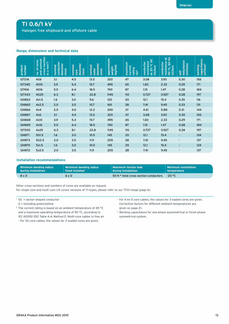
Installation recommendations
Minimum bending radius during installation
Minimum bending radius fixed installed
Maximum tensile load during installation
Minimum installation temperature
8 x D 6 x D 50 N * total cross section conductors -20 °C
TI 0.6/1 kVHalogen free shipboard and offshore cable
Other cross-sections and numbers of cores are available on request.
For single core and multi core (>5 cores) versions of TI-types, please refer to our TFXI-range (page 6).
1 SS = sector-shaped conductor
G = including green/yellow2 The current rating is based on an ambient temperature of 45 °C
and a maximum operating temperature of 90 °C, according to
IEC 60092-352 Table A.4: Method E: Multi-core cables in free air
- For 3G core cables, the values for 2 loaded cores are given.
- For 4 en 5 core cables, the values for 3 loaded cores are given.
Correction factors for different ambient temperatures are
given on page 21.3 Working capacitance for one-phase asymmetrical or three-phase
symmetrical system.
pro
du
ct
nu
mber
no.
of
core
s an
d n
om
inal
cros
s-se
ctio
n
(n x
mm
2)1
nom
inal
con
du
ctor
dia
met
er
(mm
)
nom
inal
core
dia
met
er
(mm
)
nom
inal
ou
ter
dia
met
er
(mm
)
appro
xim
ate
w
eight
(k
g/k
m)
maxim
um
cu
rren
t ra
tin
g
(A)2
con
du
ctor
resi
stan
ce
at
20
°C
DC
(Ω
/km
)
con
du
ctor
resi
stan
ce a
t 9
0 °
C, 6
0 H
z
(Ω/k
m)
self
in
du
ctan
ce
(mH
/km
)
work
ing
capaci
tan
ce
(nF/
km)3
127216 4G6 3.1 4.5 13.5 320 47 3.08 3.93 0.30 156
127345 4G10 3.9 5.4 15.7 495 65 1.83 2.33 0.29 171
127416 4G16 5.0 6.4 18.5 740 87 1.15 1.47 0.28 184
127343 4G25 6.3 8.1 22.8 1145 110 0.727 0.927 0.28 197
124863 4x1.5 1.6 3.0 9.6 120 20 12.1 15.4 0.35 116
124865 4x2.5 2.0 3.5 10.7 165 28 7.41 9.45 0.33 131
124866 4x4 2.5 4.0 12.2 240 37 4.61 5.88 0.31 144
124867 4x6 3.1 4.5 13.5 320 47 3.08 3.93 0.30 156
124868 4x10 3.9 5.4 15.7 495 65 1.83 2.33 0.29 171
124869 4x16 5.0 6.4 18.5 740 87 1.15 1.47 0.28 184
127200 4x25 6.3 8.1 22.8 1145 110 0.727 0.927 0.28 197
124871 5G1.5 1.6 3.0 10.5 145 20 12.1 15.4 - 124
124873 5G2.5 2.0 3.5 11.9 205 28 7.41 9.45 - 137
124870 5x1.5 1.6 3.0 10.5 145 20 12.1 15.4 - 124
124872 5x2.5 2.0 3.5 11.9 205 28 7.41 9.45 - 137
13DRAKA Product information MOG 2010
ShipLine
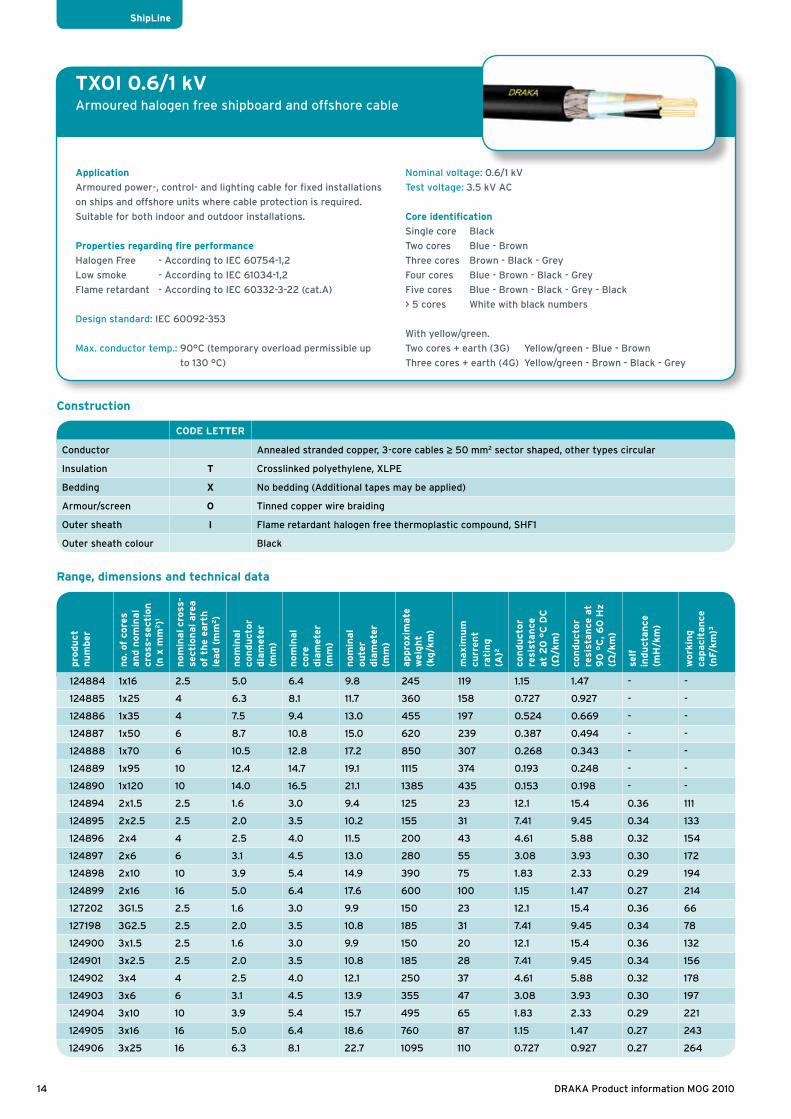
TXOI 0.6/1 kVArmoured halogen free shipboard and offshore cable
Application
Armoured power-, control- and lighting cable for fixed installations
on ships and offshore units where cable protection is required.
Suitable for both indoor and outdoor installations.
Properties regarding fire performance
Halogen Free - According to IEC 60754-1,2
Low smoke - According to IEC 61034-1,2
Flame retardant - According to IEC 60332-3-22 (cat.A)
Design standard: IEC 60092-353
Max. conductor temp.: 90°C (temporary overload permissible up
to 130 °C)
Nominal voltage: 0.6/1 kV
Test voltage: 3.5 kV AC
Core identification
Single core Black
Two cores Blue - Brown
Three cores Brown - Black - Grey
Four cores Blue - Brown - Black - Grey
Five cores Blue - Brown - Black - Grey - Black
> 5 cores White with black numbers
With yellow/green.
Two cores + earth (3G) Yellow/green - Blue - Brown
Three cores + earth (4G) Yellow/green - Brown - Black - Grey
CODE LETTER
Conductor Annealed stranded copper, 3-core cables ≥ 50 mm2 sector shaped, other types circular
Insulation T Crosslinked polyethylene, XLPE
Bedding X No bedding (Additional tapes may be applied)
Armour/screen O Tinned copper wire braiding
Outer sheath I Flame retardant halogen free thermoplastic compound, SHF1
Outer sheath colour Black
Range, dimensions and technical data
Construction
pro
du
ct
nu
mber
no.
of
core
s an
d n
om
inal
cros
s-se
ctio
n
(n x
mm
2)1
nom
inal cr
oss-
sect
ion
al are
a
of t
he
eart
h
lead (
mm
2)
nom
inal
con
du
ctor
dia
met
er
(mm
)
nom
inal
core
dia
met
er
(mm
)
nom
inal
ou
ter
dia
met
er
(mm
)
appro
xim
ate
w
eight
(k
g/k
m)
maxim
um
cu
rren
t
rati
ng
(A)2
con
du
ctor
resi
stan
ce
at
20
°C
DC
(Ω
/km
)
con
du
ctor
resi
stan
ce a
t 9
0 °
C, 6
0 H
z
(Ω/k
m)
self
in
du
ctan
ce
(mH
/km
)
work
ing
capaci
tan
ce
(nF/
km)3
124884 1x16 2.5 5.0 6.4 9.8 245 119 1.15 1.47 - -
124885 1x25 4 6.3 8.1 11.7 360 158 0.727 0.927 - -
124886 1x35 4 7.5 9.4 13.0 455 197 0.524 0.669 - -
124887 1x50 6 8.7 10.8 15.0 620 239 0.387 0.494 - -
124888 1x70 6 10.5 12.8 17.2 850 307 0.268 0.343 - -
124889 1x95 10 12.4 14.7 19.1 1115 374 0.193 0.248 - -
124890 1x120 10 14.0 16.5 21.1 1385 435 0.153 0.198 - -
124894 2x1.5 2.5 1.6 3.0 9.4 125 23 12.1 15.4 0.36 111
124895 2x2.5 2.5 2.0 3.5 10.2 155 31 7.41 9.45 0.34 133
124896 2x4 4 2.5 4.0 11.5 200 43 4.61 5.88 0.32 154
124897 2x6 6 3.1 4.5 13.0 280 55 3.08 3.93 0.30 172
124898 2x10 10 3.9 5.4 14.9 390 75 1.83 2.33 0.29 194
124899 2x16 16 5.0 6.4 17.6 600 100 1.15 1.47 0.27 214
127202 3G1.5 2.5 1.6 3.0 9.9 150 23 12.1 15.4 0.36 66
127198 3G2.5 2.5 2.0 3.5 10.8 185 31 7.41 9.45 0.34 78
124900 3x1.5 2.5 1.6 3.0 9.9 150 20 12.1 15.4 0.36 132
124901 3x2.5 2.5 2.0 3.5 10.8 185 28 7.41 9.45 0.34 156
124902 3x4 4 2.5 4.0 12.1 250 37 4.61 5.88 0.32 178
124903 3x6 6 3.1 4.5 13.9 355 47 3.08 3.93 0.30 197
124904 3x10 10 3.9 5.4 15.7 495 65 1.83 2.33 0.29 221
124905 3x16 16 5.0 6.4 18.6 760 87 1.15 1.47 0.27 243
124906 3x25 16 6.3 8.1 22.7 1095 110 0.727 0.927 0.27 264
14 DRAKA Product information MOG 2010
ShipLine

Range, dimensions and technical data
Installation recommendations
Minimum bending radius during installation
Minimum bending radius fixed installed
Maximum tensile load during installation
Minimum installation temperature
8 x D 6 x D 50 N * total cross section conductors -20 °C
ShipLine
TXOI 0.6/1 kVArmoured halogen free shipboard and offshore cable
Other cross-sections and numbers of cores are available on request
1 SS = sector-shaped conductor
G = including green/yellow2 The current rating is based on an ambient temperature of 45 °C
and a maximum operating temperature of 90 °C, according to IEC
60092-352 Table A.4:
I. For singel core cables, Method G: 3 cores spaced in free air
II. For multi-core cables, Method E: Multi-core cables in free air
- For 3G core cables, the values for 2 loaded cores are given.
- For 4 en 5 core cables, the values for 3 loaded cores are given.
Correction factors for different ambient temperatures are
given on page 23 Working capacitance for one-phase asymmetrical or three-phase
symmetrical system. The working capacitance of multicore types
n>5 depends on the way the wires are connected.
pro
du
ct
nu
mber
no.
of
core
s an
d n
om
inal
cros
s-se
ctio
n
(n x
mm
2)1
nom
inal cr
oss-
sect
ion
al are
a
of t
he
eart
h
lead (
mm
2)
nom
inal
con
du
ctor
dia
met
er
(mm
)
nom
inal
core
dia
met
er
(mm
)
nom
inal
ou
ter
dia
met
er
(mm
)
appro
xim
ate
w
eight
(k
g/k
m)
maxim
um
cu
rren
t
rati
ng
(A)2
con
du
ctor
resi
stan
ce
at
20
°C
DC
(Ω
/km
)
con
du
ctor
resi
stan
ce a
t 9
0 °
C, 6
0 H
z
(Ω/k
m)
self
in
du
ctan
ce
(mH
/km
)
work
ing
capaci
tan
ce
(nF/
km)3
124907 3x35 16 7.5 9.4 24.9 1340 137 0.524 0.669 0.25 279
124908 3x50 SS 25 6.8/12.2 8.9/14.3 24.8 1820 167 0.387 0.494 0.19 317
124909 3x70 SS 35 8.2/14.6 10.5/16.9 29.7 2580 214 0.268 0.343 0.19 336
124910 3x95 SS 50 9.7/17.3 12.1/19.7 33.1 3435 259 0.193 0.248 0.18 353
127205 3x120 SS 25 10.9/19.3 13.5/21.9 36.0 4075 301 0.153 0.198 0.18 366
127347 3x150 SS 25 12.2/21.7 15.2/24.7 39.1 4950 347 0.124 0.161 0.18 379
127203 4G1.5 2.5 1.6 3.0 10.6 175 20 12.1 15.4 0.39 135
127199 4G2.5 2.5 2.0 3.5 11.9 230 28 7.41 9.45 0.36 159
124913 4x1.5 2.5 1.6 3.0 10.6 175 20 12.1 15.4 0.39 135
124914 4x2.5 2.5 2.0 3.5 11.9 230 28 7.41 9.45 0.36 159
124915 4x4 6 2.5 4.0 13.8 340 37 4.61 5.88 0.34 181
124916 4x6 6 3.1 4.5 15.1 435 47 3.08 3.93 0.33 200
124917 4x10 10 3.9 5.4 17.3 630 65 1.83 2.33 0.31 224
124918 4x16 16 5.0 6.4 20.5 940 87 1.15 1.47 0.30 246
124919 4x25 16 6.3 8.1 24.4 1345 110 0.727 0.927 0.30 267
124920 5x1.5 2.5 1.6 3.0 11.8 210 16 12.1 15.4 - 136
124921 5x2.5 2.5 2.0 3.5 12.9 270 22 7.41 9.45 - 161
126759 6x1.5 4 1.6 3.0 12.7 240 15 12.1 15.4 - ≤145
124924 7x1.5 4 1.6 3.0 12.7 260 14 12.1 15.4 - ≤145
126760 8x1.5 6 1.6 3.0 15.5 340 13 12.1 15.4 - ≤145
124926 10x1.5 6 1.6 3.0 16.2 390 12 12.1 15.4 - ≤145
124927 12x1.5 6 1.6 3.0 16.9 440 11 12.1 15.4 - ≤145
124928 16x1.5 6 1.6 3.0 18.6 550 10 12.1 15.4 - ≤145
124929 19x1.5 6 1.6 3.0 19.7 620 9 12.1 15.4 - ≤145
124930 24x1.5 10 1.6 3.0 22.9 800 8 12.1 15.4 - ≤145
15DRAKA Product information MOG 2010
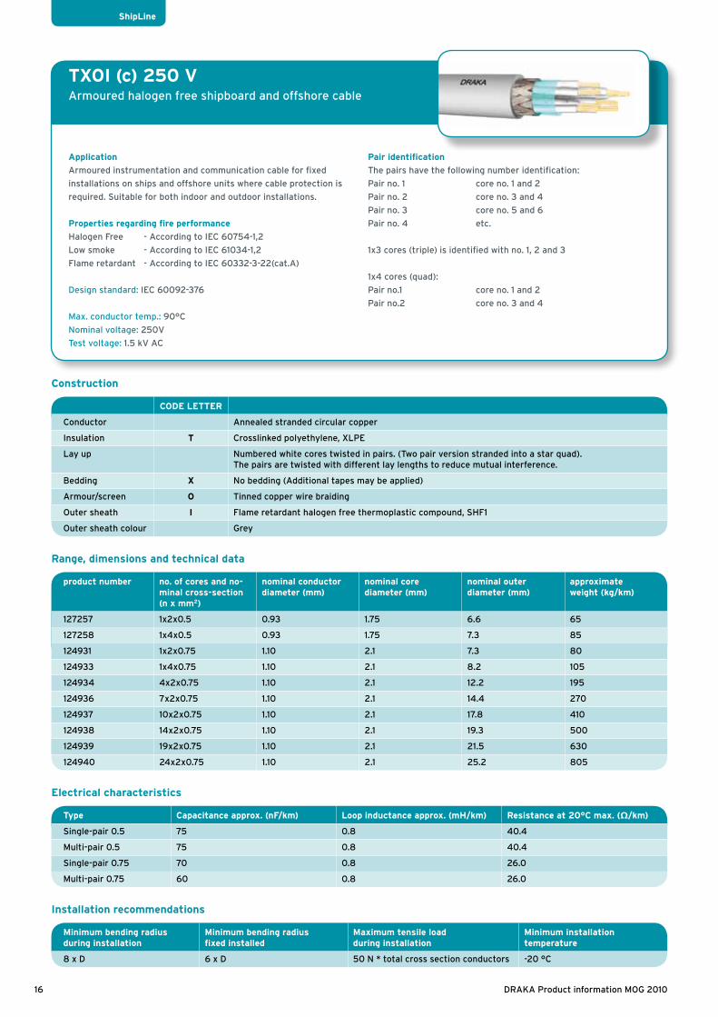
TXOI (c) 250 VArmoured halogen free shipboard and offshore cable
Application
Armoured instrumentation and communication cable for fixed
installations on ships and offshore units where cable protection is
required. Suitable for both indoor and outdoor installations.
Properties regarding fire performance
Halogen Free - According to IEC 60754-1,2
Low smoke - According to IEC 61034-1,2
Flame retardant - According to IEC 60332-3-22(cat.A)
Design standard: IEC 60092-376
Max. conductor temp.: 90°C
Nominal voltage: 250V
Test voltage: 1.5 kV AC
Pair identification
The pairs have the following number identification:
Pair no. 1 core no. 1 and 2
Pair no. 2 core no. 3 and 4
Pair no. 3 core no. 5 and 6
Pair no. 4 etc.
1x3 cores (triple) is identified with no. 1, 2 and 3
1x4 cores (quad):
Pair no.1 core no. 1 and 2
Pair no.2 core no. 3 and 4
CODE LETTER
Conductor Annealed stranded circular copper
Insulation T Crosslinked polyethylene, XLPE
Lay up Numbered white cores twisted in pairs. (Two pair version stranded into a star quad). The pairs are twisted with different lay lengths to reduce mutual interference.
Bedding X No bedding (Additional tapes may be applied)
Armour/screen O Tinned copper wire braiding
Outer sheath I Flame retardant halogen free thermoplastic compound, SHF1
Outer sheath colour Grey
Range, dimensions and technical data
Installation recommendations
Minimum bending radius during installation
Minimum bending radius fixed installed
Maximum tensile load during installation
Minimum installation temperature
8 x D 6 x D 50 N * total cross section conductors -20 °C
Type Capacitance approx. (nF/km) Loop inductance approx. (mH/km) Resistance at 20°C max. (Ω/km)
Single-pair 0.5 75 0.8 40.4
Multi-pair 0.5 75 0.8 40.4
Single-pair 0.75 70 0.8 26.0
Multi-pair 0.75 60 0.8 26.0
Electrical characteristics
Construction
product number no. of cores and no-minal cross-section(n x mm2)
nominal conductor diameter (mm)
nominal core diameter (mm)
nominal outer diameter (mm)
approximate weight (kg/km)
127257 1x2x0.5 0.93 1.75 6.6 65
127258 1x4x0.5 0.93 1.75 7.3 85
124931 1x2x0.75 1.10 2.1 7.3 80
124933 1x4x0.75 1.10 2.1 8.2 105
124934 4x2x0.75 1.10 2.1 12.2 195
124936 7x2x0.75 1.10 2.1 14.4 270
124937 10x2x0.75 1.10 2.1 17.8 410
124938 14x2x0.75 1.10 2.1 19.3 500
124939 19x2x0.75 1.10 2.1 21.5 630
124940 24x2x0.75 1.10 2.1 25.2 805
ShipLine
16 DRAKA Product information MOG 2010

BI FR 0.6/1 kVHalogen free shipboard and offshore cable, fire resistant
Application
Unarmoured power and control cable for fixed installations on
ships and offshore units where cable protection is not required.
For instrumentation, communication, control, alarm, emergency and
critical systems. Suitable for both indoor and outdoor installations.
Properties regarding fire performance
Halogen Free - According to IEC 60754-1,2
Low smoke - According to IEC 61034-1,2
Flame retardant - According to IEC 60332-3-22 (cat.A)
Fire resistant - According to IEC 60331
Design standard: IEC 60092-353
Max. conductor temp.: 90°C (temporary overload permissible up
to 130 °C)
Nominal voltage: 0.6/1 kV
Test voltage: 3.5 kV AC
Core identification
Two cores Blue - Brown
Three cores Brown - Black - Grey
Four cores Blue - Brown - Black - Grey
CODE LETTER
Conductor Annealed stranded circular copper
Insulation B Mica-tape/crosslinked polyethylene, XLPE
Outer sheath I Flame retardant halogen free thermoplastic compound, SHF1
Outer sheath colour Green
Construction
Range, dimensions and technical data
Installation recommendations
Minimum bending radius during installation
Minimum bending radius fixed installed
Maximum tensile load during installation
Minimum installation temperature
8 x D 6 x D 50 N * total cross section conductors -20 °C
ShipLine Fire Resistant
Other cross-sections and numbers of cores are available on request
1 The current rating is based on an ambient temperature of 45 °C
and a maximum operating temperature of 90 °C, according to
IEC 60092-352 Table A.4: Method E: Multi-core cables in free air
- For 4 core cables, the values for 3 loaded cores are given.
Correction factors for different ambient temperatures and cables laid
in bundles are given on page 21.2 Working capacitance for one-phase asymmetrical or three-phase
symmetrical system.
pro
du
ct
nu
mber
no.
of
core
s an
d n
om
inal
cros
s-se
ctio
n
(n x
mm
2)
nom
inal
con
du
ctor
dia
met
er
(mm
)
nom
inal
core
dia
met
er
(mm
)
nom
inal
ou
ter
dia
met
er
(mm
)
appro
xim
ate
w
eight
(k
g/k
m)
maxim
um
cu
rren
t ra
tin
g (
A)1
con
du
ctor
resi
stan
ce
at
20
°C
DC
(Ω
/km
)
con
du
ctor
resi
stan
ce a
t 9
0 °
C, 6
0 H
z
(Ω/k
m)
self
in
du
ctan
ce
(mH
/km
)
work
ing
capaci
tan
ce
(nF/
km)2
126458 2x1.5 1.6 3.3 8.5 85 23 12.1 15.4 0.36 54
126461 2x2.5 2.0 3.8 9.5 110 31 7.41 9.45 0.34 59
126459 3x1.5 1.6 3.3 9.5 110 20 12.1 15.4 0.36 108
126462 3x2.5 2.0 3.8 10.0 145 28 7.41 9.45 0.34 118
126463 3x4 2.5 4.3 11.5 205 37 4.61 5.88 0.32 130
126460 4x1.5 1.6 3.3 10.0 135 20 12.1 15.4 0.39 128
127061 4x6 3.1 4.8 14.5 340 47 3.08 3.93 0.32 161
17DRAKA Product information MOG 2010

BXOI FR 0.6/1 kVArmoured halogen free shipboard and offshore cable, fire resistant
Application
Armoured power-, control- and lighting cable for fixed installations
on ships and offshore units where cable protection is required. For
instrumentation, communication, control, alarm, emergency and
critical systems in both EX- and safe areas. Suitable for both indoor
and outdoor installations.
Properties regarding fire performance
Halogen Free - According to IEC 60754-1,2
Low smoke - According to IEC 61034-1,2
Flame retardant - According to IEC 60332-3-22 (cat.A)
Fire resistant - According to IEC 60331
Design standard: IEC 60092-353
Max. conductor temp.: 90°C (temporary overload permissible up
to 130 °C)
Nominal voltage: 0.6/1 kV
Test voltage: 3.5 kV AC
Pair identification
Two cores Blue - Brown
Three cores Brown - Black - Grey
Five cores Blue - Brown - Black - Grey - Black
> 5 cores White with black numbers
CODE LETTER
Conductor Annealed stranded circular copper
Insulation B Mica-tape/crosslinked polyethylene, XLPE
Inner sheath X No bedding (Additional tapes may be applied)
Armour/screen O Tinned copper wire braiding
Outer sheath I Flame retardant halogen free thermoplastic compound, SHF1
Outer sheath colour Green
Range, dimensions and technical data
Construction
Installation recommendations
Minimum bending radius during installation
Minimum bending radius fixed installed
Maximum tensile load during installation
Minimum installation temperature
8 x D 6 x D 50 N * total cross section conductors -20 °C
ShipLine Fire Resistant
Other cross-sections and numbers of cores are available on request
1 The current rating is based on an ambient temperature of 45 °C
and a maximum operating temperature of 90 °C, according to
IEC 60092-352 Table A.4: Method E: Multi-core cables in free air
- For 5 core cables, the values for 3 loaded cores are given.
Correction factors for different ambient temperatures are
given on page 21.
2 Working capacitance for one-phase asymmetrical or three-phase
symmetrical system. The working capacitance of multicore types n>5
depends on the way the wires are connected
pro
du
ct
nu
mber
no.
of
core
s an
d n
om
inal
cros
s-se
ctio
n
(n x
mm
2)
nom
inal cr
oss-
sect
ion
al are
a
of t
he
eart
h
lead (
mm
2)
nom
inal
con
du
ctor
dia
met
er
(mm
)
nom
inal
core
dia
met
er
(mm
)
nom
inal
ou
ter
dia
met
er
(mm
)
appro
xim
ate
w
eight
(k
g/k
m)
maxim
um
cu
rren
t
rati
ng
(A)1
con
du
ctor
resi
stan
ce
at
20
°C
DC
(Ω
/km
)
con
du
ctor
resi
stan
ce a
t 9
0 °
C, 6
0 H
z
(Ω/k
m)
self
in
du
ctan
ce
(mH
/km
)
work
ing
capaci
tan
ce
(nF/
km)2
125758 2x1.5 2.5 1.6 3.3 10.0 135 23 12.1 15.4 0.39 130
125764 2x2.5 2.5 2.0 3.8 10.5 160 31 7.41 9.45 0.36 144
125760 3x1.5 2.5 1.6 3.3 10.5 160 20 12.1 15.4 0.39 145
125763 3x2.5 2.5 2.0 3.8 11.0 205 28 7.41 9.45 0.36 162
126457 3x4 4 2.5 4.3 12.5 275 37 4.61 5.88 0.34 185
126986 3x6 6 3.1 4.8 14.5 380 47 3.08 3.93 0.32 208
125765 3x10 10 4.4 5.8 16.8 535 65 1.83 2.33 0.30 219
126456 5x1.5 4 1.6 3.3 12.5 230 16 12.1 15.4 - 161
125761 7x1.5 6 1.6 3.3 13.5 290 14 12.1 15.4 - > 165
125762 12x1.5 6 1.6 3.3 18.0 480 11 12.1 15.4 - >165
18 DRAKA Product information MOG 2010

Installation recommendations
Minimum bending radius during installation
Minimum bending radius fixed installed
Maximum tensile load during installation
Minimum installation temperature
8 x D 6 x D 50 N * total cross section conductors -20 °C
Type Capacitance approx. (nF/km) Loop inductance approx. (mH/km) Resistance at 20°C max. (Ω/km)
Single/multi-pair 0.75 80 0.8 26.0
Single-pair 1.5 90 0.8 12.8
Electrical characteristics
BXOI FR 250 VArmoured halogen free shipboard and offshore cable, fire resistant
Application
Armoured instrumentation and communication cable for fixed
installations on ships and offshore units where cable protection
is required. For instrumentation, communication, control, alarm,
emergency and critical systems in both EX- and safe areas. Suitable
for both indoor and outdoor installations.
Properties regarding fire performance
Halogen Free - According to IEC 60754-1,2
Low smoke - According to IEC 61034-1,2
Flame retardant - According to IEC 60332-3-22 (cat.A)
Fire resistant - According to IEC 60331
Design standard: IEC 60092-353
Max. conductor temp.: 90°C
Nominal voltage: 250V
Test voltage: 1.5 kV AC
Core identification
The pairs have the following number identification:
Pair no. 1 core no. 1 and 2
Pair no. 2 core no. 3 and 4
Pair no. 3 core no. 5 and 6
Pair no. 4 etc
CODE LETTER
Conductor Annealed stranded circular copper
Insulation B Mica-tape/crosslinked polyethylene, XLPE
Lay up Colour coded cores twisted together and wrapped with polyester tape. The pairs are twisted with different lay length to reduce mutual interference. Pairs are identified by numbered tape.
Bedding X No bedding (Additional tapes may be applied)
Armour/screen O Tinned copper wire braiding
Outer sheath I Flame retardant halogen free thermoplastic compound, SHF1
Outer sheath colour Green
Construction
Range, dimensions and technical data
ShipLine Fire Resistant
product number no. of cores and no-minal cross-section (n x mm2)
nominal conductor diameter (mm)
nominal core diameter (mm)
nominal outer diameter (mm)
approximate weight (kg/km)
125560 1x2x0.75 1.10 2.5 8.5 95
125766 2x2x0.75 1.10 2.5 13.0 170
127139 4x2x0.75 1.10 2.5 15.5 240
125767 7x2x0.75 1.10 2.5 18.5 390
130049 19x2x0.75 1.10 2.5 23.5 1040
127041 1x2x1.5 1.60 3.0 9.5 115
19DRAKA Product information MOG 2010

Data cables
Data cables of the Universal Cable series UC are always in
use wherever it is a question of high-speed data transmission
in local networks (LAN). Whether Cat5e (Class D), Cat6 (Class
E), Cat6a (Class Ea), Cat7 (Class Fa), Class7+ or multimedia
- all data cables are in accordance with ISO/IEC 11801, EN
50173 and EIA/TIA 568A.
On ships, data cables of the UC series are used for
standarized and manufacturer-independent networks - Token
Ring, Ethernet, ISDN, TPDDI, Fast-Ethernet 100BaseTX, ATM,
Gigabit-Ethernet 1000Base T or 10 GbE.
RF cables
The radio-frequency cables are used in transmitter and
receiver installations in radio communication as well as in the
entire field of commercial radio-frequency technology and
electronics.
RG cables of the American standard according to MIL-C-17G
have become the global standard. They are always applied
where high quality is required.
On ships, they serve as cables for transmitters and receivers
in the radio technology and as connection cables in the
navigation technology.
Video and Audio cables
Audio cables are a perfect basis for digital and analogue
transmission of audio signals. The digital audio cables are in
accordance with the AES/EBU standard.
Video cables are used as coaxial cables with a charcteristic
impendence of 75Ω for the connection of recording and
intermediate amplifiers as well as monitors and cameras.
The specified frequency range up to 5000 MHz permits the
application of the video cables for serial digital transmission,
HDTV and future transmission technology.
In the ship’s own television studio for example, audio and
video cables are applied in order to enable the transmission
from the studio to the cabin.
CATV cables
CATV cables are used in private and commercial trunk lines
and TV signal distribution networks. They can be applied
from the headend. Drop cables are used in private and
commercial TV signal distribution networks and as antenna
cables for terrestric and satellite broadcast systems.
On ships, CATV cables are applied for example for the
transmission of TV channels which are received via satellite
TV or terrestric antennas and transmitted to the cabins.
Overview
Data cables
20 DRAKA Product information MOG 2010

Electrical characteristics of cables
Data cables
Ambient temp. °C 25 30 35 40 45 50 55 60 65 70 75
Rating factor 1.2 1.15 1.11 1.05 1 0.94 0.88 0.82 0.74 0.67 0.58
Maximum resistance of copper conductors according to IEC 60228 Class 2
Conductor resistance
Influence of temperature on the conductor resistance
Correction factors for ambient temperatures other than 45 ˚C, according to IEC 60092
Current ratings for continuous load
Minimum number of strands
mm2 Circular Conductor
Sector-shaped Conductor
Ω/km
1.5 7 - 12.1
2.5 7 - 7.41
4 7 - 4.61
6 7 - 3.08
10 7 - 1.83
16 7 - 1.15
25 7 - 0.727
35 19 (7) - 0.524
50 19 (19) 19 (6) 0.387
70 37 (19) 37 (12) 0.268
95 37(19) 37 (15) 0.193
120 61 (37) 37 (18) 0.153
150 61 (37) 37 (18) 0.124
Temp. °C Correction factor
20 1.000
25 1.020
30 1.039
35 1.059
40 1.079
45 1.098
50 1.118
55 1.138
60 1.157
65 1.177
70 1.196
75 1.216
80 1.236
85 1.255
90 1.275
Short circuit currentThe maximum permissible short circuit current for
different cables is given in the figure aside.
This figure is based on the formula:
lk = 143·S/√t
lk = the maximum permissible short circuit current
S = the cross-section of the conductor in mm2
t = the duration of the short circuit in seconds
Tk start = 90 ˚C
Tk end = 250 ˚C
The formula is applicable for an increase in temperature
from 90 ˚C at the start to 250 ˚C at the end of the
short circuit, when the duration of the short circuit is
less than 5 seconds.
100,0
10,0
1,0
0,1
0,00,1 1,0 10,0
1,5
2,5
4
6
10
16
25
35
50
70
95
120
150
Permissible short circuit current
Sh
ort
cir
cuit
cu
rre
nt
in k
A
Cro
ss-s
ect
ion
of
the
co
nd
uct
or
in m
m2
Duration of the short circuit in seconds
Table 1 Table 2
Table 3
21DRAKA Product information MOG 2010

Electrical characteristics of cables
Data cables
The calculation of the working capacitance
Number of cores Cable type Voltage type Working capacitance
2 unscreened AC C12
screened AC symmetricalAC asymmetrical, screen grounded
C12 + ½.C11
C12 + C11
3 unscreened 3 phase AC symmetrical2 phase AC symmetrical, one core grounded
3.C12
1½.C12
screened 3 phase AC symmetrical2 phase AC symmetrical, one core grounded
3.C12 + C11
1½.C12 + ½.C11
4 unscreened 3 phase AC, one core grounded CS = 3.C12 + C13
CR,T = 2½.C12 + 3.C13
screened 3 phase AC, one core and screen grounded CS = C11 + 3.C12 + C13
CR,T = C11 + 2½.C12 + 3.C13
Working capacitance
The actual value of the working capacitance of cables depends on the
cable type, the electrical circuit in which the cable functions and, for
unscreened and unarmoured cables, the method of installation.
The working capacitance of a cable can be calculated by substitution
of the partial capacitances in the formulas of table 4 by the value of
table 5 and 6.
As the theoretical calculation of the working capacitance of multicore
cables, 1.5 or 2.5 mm2, is very complex, no partial capacitances have
been indicated. Generally, the value of the working capacitance will,
in the case, be less than 100 nF/km.
CS = working capacitance of phase S
CR,T = working capacitance of phases R and T
screen
C 22
C 23
C 14
C 13
C 24
C 33
C 11 C 44
C 12 C 34
2 3
1 4
screen
C 22
C 13C 11 C 33
C 12 C 23
2
1 4
screen
C 11 C 22C 12
1 2
C 23
C 14
C 13
C 24C 12 C 34
2 3
1 4C 13
C 12 C 23
2
1 4
C 12
1 2
The partial capacitance are defined as follows:
Capacitance of Draka marine cables
Table 4
22 DRAKA Product information MOG 2010
Electrical characteristics of cables
Data cables
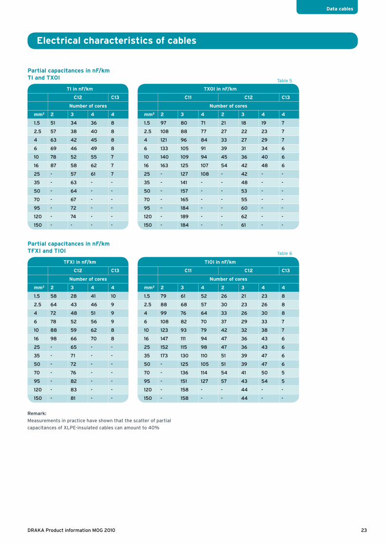
Partial capacitances in nF/kmTI and TXOI
Partial capacitances in nF/kmTFXI and TIOI
TI in nF/km
C12 C13
Number of cores
mm2 2 3 4 4
1.5 51 34 36 8
2.5 57 38 40 8
4 63 42 45 8
6 69 46 49 8
10 78 52 55 7
16 87 58 62 7
25 - 57 61 7
35 - 63 - -
50 - 64 - -
70 - 67 - -
95 - 72 - -
120 - 74 - -
150 - - - -
TFXI in nF/km
C12 C13
Number of cores
mm2 2 3 4 4
1.5 58 28 41 10
2.5 64 43 46 9
4 72 48 51 9
6 78 52 56 9
10 88 59 62 8
16 98 66 70 8
25 - 65 - -
35 - 71 - -
50 - 72 - -
70 - 76 - -
95 - 82 - -
120 - 83 - -
150 - 81 - -
TXOI in nF/km
C11 C12 C13
Number of cores
mm2 2 3 4 2 3 4 4
1.5 97 80 71 21 18 19 7
2.5 108 88 77 27 22 23 7
4 121 96 84 33 27 29 7
6 133 105 91 39 31 34 6
10 140 109 94 45 36 40 6
16 163 125 107 54 42 48 6
25 - 127 108 - 42 - -
35 - 141 - - 48 - -
50 - 157 - - 53 - -
70 - 165 - - 55 - -
95 - 184 - - 60 - -
120 - 189 - - 62 - -
150 - 184 - - 61 - -
TIOI in nF/km
C11 C12 C13
Number of cores
mm2 2 3 4 2 3 4 4
1.5 79 61 52 26 21 23 8
2.5 88 68 57 30 23 26 8
4 99 76 64 33 26 30 8
6 108 82 70 37 29 33 7
10 123 93 79 42 32 38 7
16 147 111 94 47 36 43 6
25 152 115 98 47 36 43 6
35 173 130 110 51 39 47 6
50 - 125 105 51 39 47 6
70 - 136 114 54 41 50 5
95 - 151 127 57 43 54 5
120 - 158 - - 44 - -
150 - 158 - - 44 - -
Remark:
Measurements in practice have shown that the scatter of partial
capacitances of XLPE-insulated cables can amount to 40%
Table 5
Table 6
23DRAKA Product information MOG 2010

Draka Kabel B.V. Hamerstraat 2-4 | 1021 JV Amsterdam | Postbus 1013 | 1000 BA Amsterdam
T. 020 637 99 11 | F. 020 637 93 63 | [email protected] | www.drakaservice.nl