Embed Size (px)
Citation preview
TMS500-2Product Guide
ASME B30.5Imperial 85%
Metric 85%
Features• 36,3 t (40 USt) capacity
• 8,8 m – 29 m (29 ft – 95 ft) four-section full-power boom
• 9,8 m – 31 m (32 ft – 102 ft) four-section full-power boom
• 7,9 m – 13,7 m (26 ft – 45 ft) offsettable telescopic swingaway extension
• Crane Control System (CCS)
• 261 kW (350 bhp) Cummins ISL9 engine
2 Grove TMS500-2
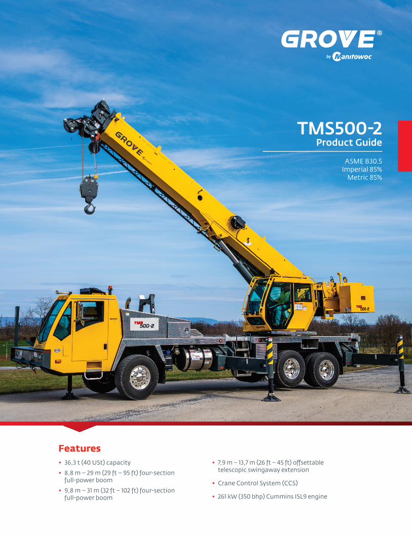
The TMS500-2 is designed for superior roadability and fast setup.
Two four-section boom options for flexibility• 8,8 m – 29,0 m (29 ft – 95 ft) four-section, synchronized,
full-power boom • 9,8 m – 31,0 m (32 ft – 102 ft) four-section, synchronized,
full-power boom
Optional extension• 7,9 m – 13,7m (26 ft – 45 ft) telescoping swingaway lattice extension with manual offsets at 0°, 15° and 30° • Maximum tip height: 39,1 m (128.2 ft) with 29 m (95 ft) boom • Maximum tip height: 42,0 m (134.8 ft) with 31 m (102 ft) boom
Outriggers• Three outrigger position settings (0%, 50% and 100%)• Inverted outrigger jacks• Removable aluminum outrigger floats• Standard auto leveling system• Equipped with smart length sensing outrigger extension cylinders. This replaces traditional string pots measuring system to improve serviceability and increase accuracy.
Counterweight• Removable counterweight inserts for a lightweight travel configuration• Two counterweight packages available: 3629 kg (8000 lb) and 2495 kg (5500 lb)
CraneSTAR is an exclusive and innovative crane asset management system
that helps improve your profitability and reduce costs by remotely monitoring critical crane data. Visit www.cranestar.com for more information.
Features
Crane Control System (CCS)• Hardware and software that integrates the Crane Control with the Rated Capacity Limiter (RCL) to create one system• Tilting, full-color, high-resolution Operating and RCL displays for improved visibility• Designed for maximum operator comfort• Parts commonality across Grove, Manitowoc and Potain product lines to enhance operator familiarization and serviceability• Working range limiter• Programmable function speeds and ramps
GROVE TMS500-2
3Grove TMS500-2
Manitowoc Crane Care when you need it. The assurance of the world’s most advanced crane service and support to get you back to work fast.
Manitowoc Finance helps you get right to work generating profits for your business. Financial tools that help you capitalize on opportunity with solutions that fit your needs.
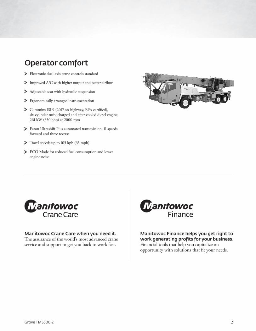
Operator comfortElectronic dual-axis crane controls standard
Improved A/C with higher output and better airflow
Adjustable seat with hydraulic suspension
Ergonomically arranged instrumentation
Cummins ISL9 (2017 on-highway, EPA certified), six-cylinder turbocharged and after-cooled diesel engine, 261 kW (350 bhp) at 2000 rpm
Eaton Ultrashift Plus automated transmission, 11 speeds forward and three reverse
Travel speeds up to 105 kph (65 mph)
ECO Mode for reduced fuel consumption and lower engine noise
4 Grove TMS500-2
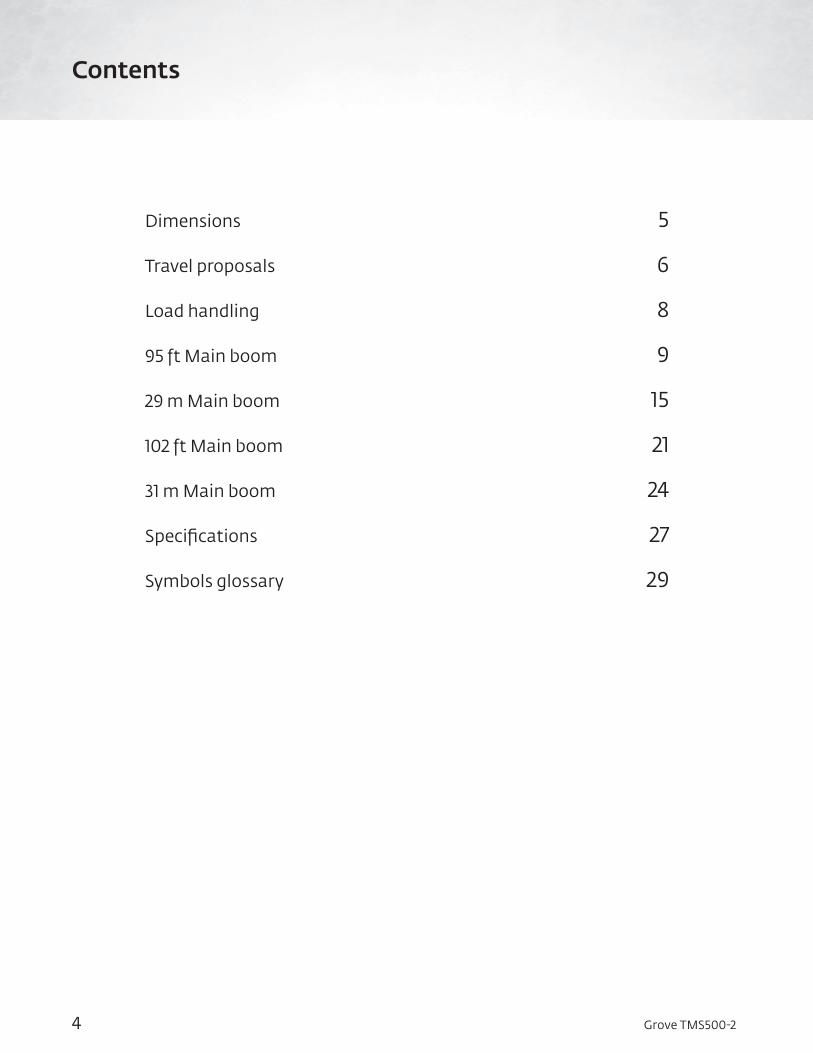
Dimensions 5
Travel proposals 6
Load handling 8
95 ft Main boom 9
29 m Main boom 15
102 ft Main boom 21
31 m Main boom 24
Specifications 27
Symbols glossary 29
Contents
5Grove TMS500-2
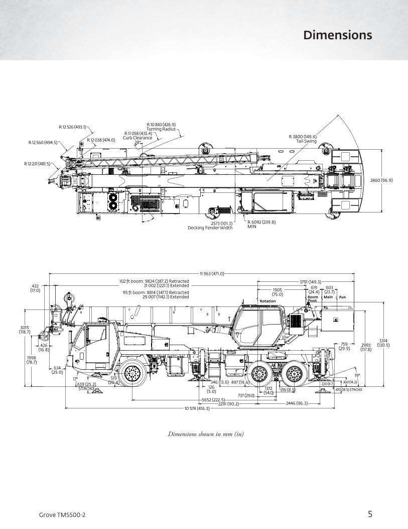
Dimensions shown in mm (in)
Dimensions
10 574 (416.3)2291 (90.2)
5652 (222.5)
126 (5.0)
346 (13.6) 497 (19.6)
2446 (96.3)
216 (8.5)737 (29.0)
1372 (54.0)
220 (8.7)
470 (18.5) STROKE
360 (14.2)
19°
759 (29.9)
2993 (117.8)
3314 (130.5)
3015 (118.7)
1998 (78.7)
634 (25.0)
426 (16.8)
432 (17.0)
11 963 (471.0)
102 ft boom: 9834 (387.2) Retracted 31 002 (1221.1) Extended
17°639 (25.2) STROKE
519 (20.4)
1905 (75.0)
3791 (149.3)603
(23.7)619
(24.4)95 ft boom: 8814 (347.1) Retracted 29 007 (1142.1) Extended C
LCL
CL
CL
RotationBoom Pivot
Main Aux
2573 (101.3)Decking Fender Width
R 6092 (239.8)MIN
R 3800 (149.6)Tail Swing
2460 (96.9)
R 10 843 (426.9)Turning Radius
R 11 058 (435.4)Curb Clearance
28°
R 12 526 (493.1)
R 12 038 (474.0)R 12 560 (494.5)
R 12 231 (481.5)
38°
6 Grove TMS500-2
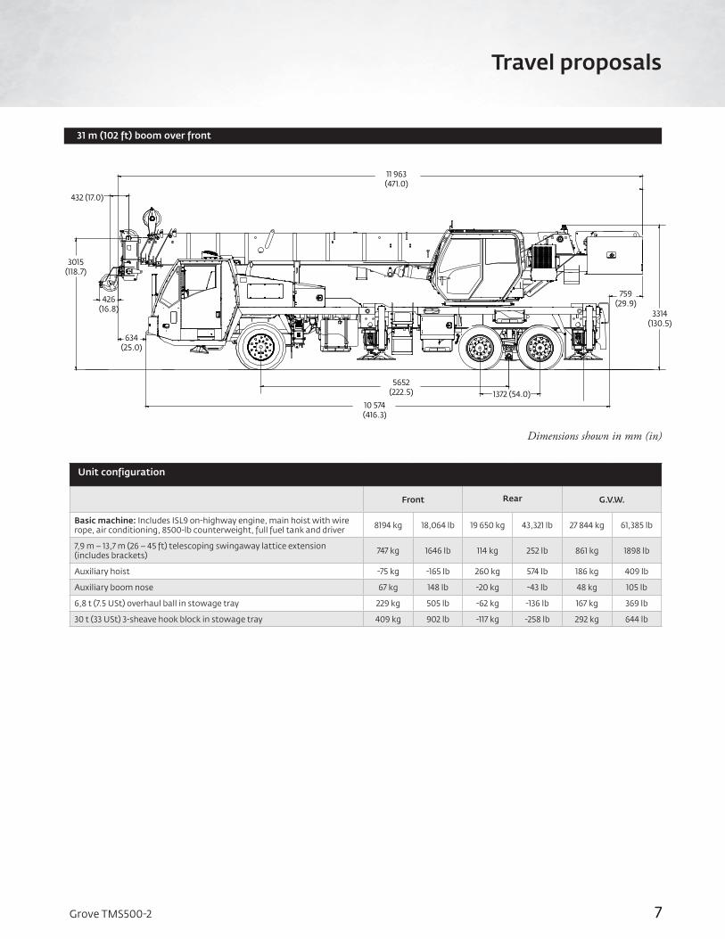
426 (16.8)
432 (17.0)
1998 (78.7)
47 (1.9) 10 574 (416.3)
5652 (222.5)
1372 (54.0)
759 (29.9)
3314 (130.5)
10 942 (430.8)
Dimensions shown in mm (in)
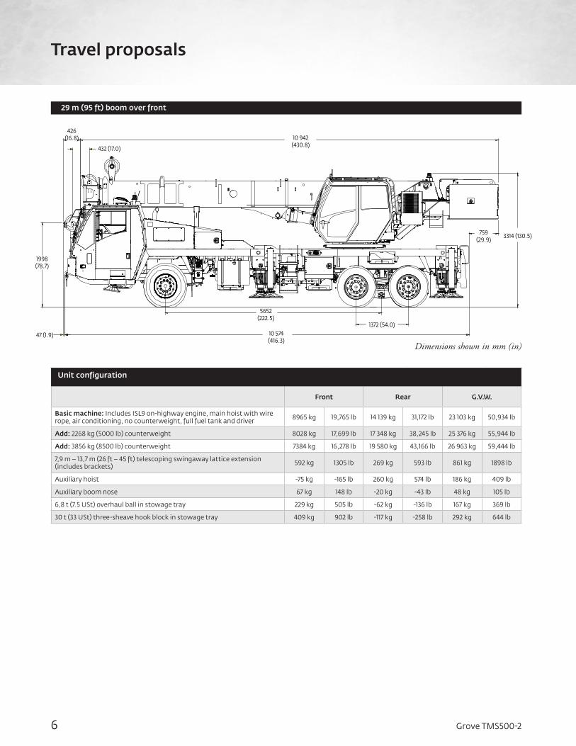
Unit configuration
Front Rear G.V.W.
Basic machine: Includes ISL9 on-highway engine, main hoist with wire rope, air conditioning, no counterweight, full fuel tank and driver 8965 kg 19,765 lb 14 139 kg 31,172 lb 23 103 kg 50,934 lb
Add: 2268 kg (5000 lb) counterweight 8028 kg 17,699 lb 17 348 kg 38,245 lb 25 376 kg 55,944 lb
Add: 3856 kg (8500 lb) counterweight 7384 kg 16,278 lb 19 580 kg 43,166 lb 26 963 kg 59,444 lb
7,9 m – 13,7 m (26 ft – 45 ft) telescoping swingaway lattice extension (includes brackets) 592 kg 1305 lb 269 kg 593 lb 861 kg 1898 lb
Auxiliary hoist -75 kg -165 lb 260 kg 574 lb 186 kg 409 lb
Auxiliary boom nose 67 kg 148 lb -20 kg -43 lb 48 kg 105 lb
6,8 t (7.5 USt) overhaul ball in stowage tray 229 kg 505 lb -62 kg -136 lb 167 kg 369 lb
30 t (33 USt) three-sheave hook block in stowage tray 409 kg 902 lb -117 kg -258 lb 292 kg 644 lb
Travel proposals
29 m (95 ft) boom over front
7Grove TMS500-2
Dimensions shown in mm (in)
10 574 (416.3)
5652 (222.5) 1372 (54.0)
759 (29.9)
3314 (130.5)
634 (25.0)
426 (16.8)
432 (17.0)
11 963 (471.0)
3015 (118.7)
7
Travel proposals
Unit configuration
Front Rear G.V.W.
Basic machine: Includes ISL9 on-highway engine, main hoist with wire rope, air conditioning, 8500-lb counterweight, full fuel tank and driver 8194 kg 18,064 lb 19 650 kg 43,321 lb 27 844 kg 61,385 lb
7,9 m – 13,7 m (26 – 45 ft) telescoping swingaway lattice extension (includes brackets) 747 kg 1646 lb 114 kg 252 lb 861 kg 1898 lb
Auxiliary hoist -75 kg -165 lb 260 kg 574 lb 186 kg 409 lb
Auxiliary boom nose 67 kg 148 lb -20 kg -43 lb 48 kg 105 lb
6,8 t (7.5 USt) overhaul ball in stowage tray 229 kg 505 lb -62 kg -136 lb 167 kg 369 lb
30 t (33 USt) 3-sheave hook block in stowage tray 409 kg 902 lb -117 kg -258 lb 292 kg 644 lb
31 m (102 ft) boom over front
8 Grove TMS500-2
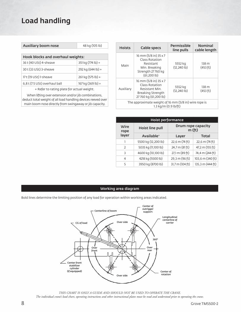
Over front
Center front stabilizer cylinder
(if equipped)
Over side
Center of rotation
Over rear
360°
Over side
Longitudinal centerline of
carrier
Center of outrigger supportCenterline of boom
CG of load
THIS CHART IS ONLY A GUIDE AND SHOULD NOT BE USED TO OPERATE THE CRANE. The individual crane’s load chart, operating instructions and other instructional plates must be read and understood prior to operating the crane.
Bold lines determine the limiting position of any load for operation within working areas indicated.
Working area diagram
Auxiliary boom nose 48 kg (105 lb)
Hook blocks and overhaul weights:
36 t (40 USt) 4-sheave 351 kg (774 lb) +
30 t (33 USt) 3-sheave 292 kg (644 lb) +
17 t (19 USt) 1-sheave 261 kg (575 lb) +
6,8 t (7.5 USt) overhaul ball 167 kg (369 lb) +
+ Refer to rating plate for actual weight.
When lifting over extension and/or jib combinations, deduct total weight of all load handling devices reeved over
main boom nose directly from swingaway or jib capacity.
Hoists Cable specs Permissible line pulls
Nominal cable length
Main
16 mm (5/8 in) 35 x 7 Class Rotation
Resistant Min. Breaking
Strength 27 760 kg (61,200 lb)
5552 kg(12,240 lb)
138 m(453 ft)
Auxiliary
16 mm (5/8 in) 35 x 7 Class Rotation Resistant Min.
Breaking Strength 27 760 kg (61,200 lb)
5552 kg (12,240 lb)
138 m (453 ft)
The approximate weight of 16 mm (5/8 in) wire rope is 1.3 kg/m (0.9 lb/ft)
Hoist performance
Wire rope layer
Hoist line pull Drum rope capacitym (ft)
Available* Layer Total
1 5500 kg (12,200 lb) 22,6 m (74 ft) 22,6 m (74 ft)
2 5035 kg (11,100 lb) 24,7 m (81 ft) 47,2 m (155 ft)
3 4600 kg (10,100 lb) 27,1 m (89 ft) 74,4 m (244 ft)
4 4218 kg (9300 lb) 29,3 m (96 ft) 103,6 m (340 ft)
5 3950 kg (8700 lb) 31,7 m (104 ft) 135,3 m (444 ft)
Load handling
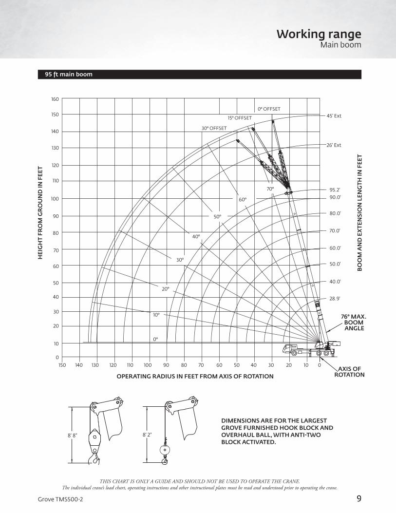
9Grove TMS500-2
95 ft main boom
THIS CHART IS ONLY A GUIDE AND SHOULD NOT BE USED TO OPERATE THE CRANE. The individual crane’s load chart, operating instructions and other instructional plates must be read and understood prior to operating the crane.
OPERATING RADIUS IN FEET FROM AXIS OF ROTATION
BO
OM
AN
D E
XTE
NSI
ON
LEN
GTH
IN F
EET
HEI
GH
T FR
OM
GR
OU
ND
IN F
EET
76° MAX. BOOM ANGLE
AXIS OFROTATION
9
Working rangeMain boom
DIMENSIONS ARE FOR THE LARGEST GROVE FURNISHED HOOK BLOCK AND OVERHAUL BALL, WITH ANTI-TWO BLOCK ACTIVATED.
20
30
40
50
60
70
80
90
100
110
120
140
130
150
10
0
160
102030506070 40130 120 110 100 90 80150 140
10°
0°
30°
40°
50°
60°
70°
20°
30° OFFSET
15° OFFSET
0° OFFSET
95.2'90.0'
80.0'
70.0'
60.0'
50.0'
40.0'
28.9'
26' Ext
45' Ext
0
8' 8" 8' 2"
10 Grove TMS500-2
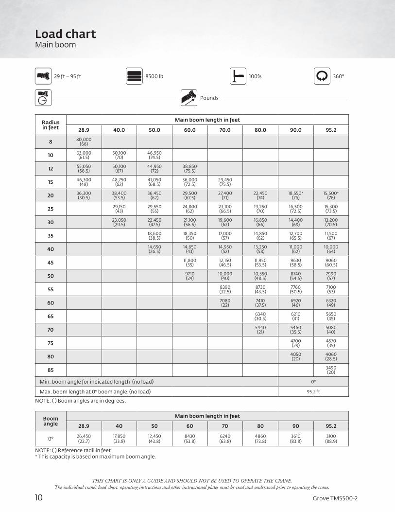
Load chartMain boom
Radius in feet
Main boom length in feet
28.9 40.0 50.0 60.0 70.0 80.0 90.0 95.2
8 80,000 (66)
10 63,000 (61.5)
50,100 (70)
46,950 (74.5)
12 55,050 (56.5)
50,100 (67)
44,950 (72)
38,850 (75.5)
15 46,300 (48)
48,750 (62)
41,050 (68.5)
36,000 (72.5)
29,450 (75.5)
20 36,300 (30.5)
38,400 (53.5)
36,450 (62)
29,500 (67.5)
27,400 (71)
22,450 (74)
18,550* (76)
15,500* (76)
25 29,150 (43)
29,550 (55)
24,800 (62)
23,100 (66.5)
19,250 (70)
16,500 (72.5)
15,300 (73.5)
30 23,050 (29.5)
23,450 (47.5)
21,100 (56.5)
19,600 (62)
16,850 (66)
14,400 (69)
13,200 (70.5)
35 18,600 (38.5)
18,350 (50)
17,000 (57)
14,850 (62)
12,700 (65.5)
11,500 (67)
40 14,650 (26.5)
14,650 (43)
14,950 (52)
13,250 (58)
11,000 (62)
10,000 (64)
45 11,800 (35)
12,150 (46.5)
11,950 (53.5)
9630 (58.5)
9060 (60.5)
50 9710 (24)
10,000 (40)
10,350 (48.5)
8740 (54.5)
7990 (57)
55 8390 (32.5)
8730 (43.5)
7760 (50.5)
7100 (53)
60 7080 (22)
7410 (37.5)
6920 (46)
6320 (49)
65 6340 (30.5)
6210 (41)
5650 (45)
70 5440 (21)
5460 (35.5)
5080 (40)
75 4700 (29)
4570 (35)
80 4050 (20)
4060 (28.5)
85 3490 (20)
Min. boom angle for indicated length (no load) 0°
Max. boom length at 0° boom angle (no load) 95.2 ft
NOTE: ( ) Boom angles are in degrees.
Boom angle
Main boom length in feet
28.9 40 50 60 70 80 90 95.2
0° 26,450 (22.7)
17,850 (33.8)
12,450 (43.8)
8430 (53.8)
6240 (63.8)
4860 (73.8)
3610 (83.8)
3100 (88.9)
NOTE: ( ) Reference radii in feet.* This capacity is based on maximum boom angle.
8500 lb 100% 360°
Pounds
29 ft – 95 ft
THIS CHART IS ONLY A GUIDE AND SHOULD NOT BE USED TO OPERATE THE CRANE. The individual crane’s load chart, operating instructions and other instructional plates must be read and understood prior to operating the crane.
11Grove TMS500-2
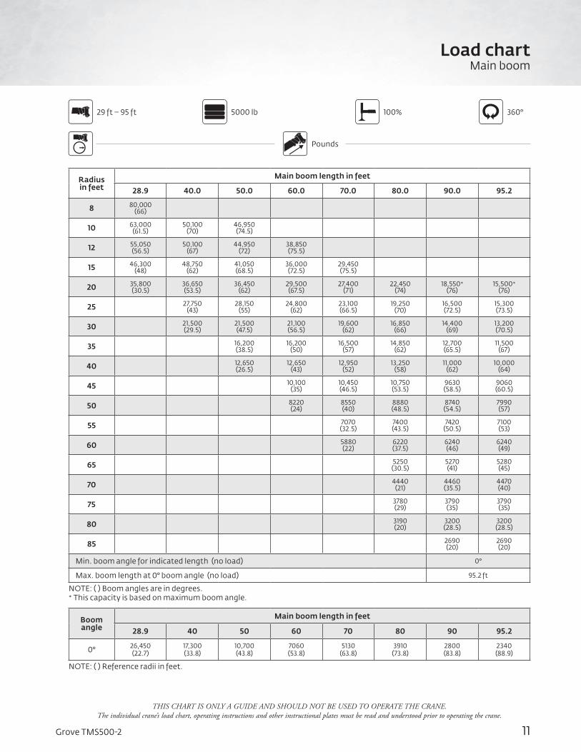
5000 lb 100% 360°
Pounds
29 ft – 95 ft
Radius in feet
Main boom length in feet
28.9 40.0 50.0 60.0 70.0 80.0 90.0 95.2
8 80,000 (66)
10 63,000 (61.5)
50,100 (70)
46,950 (74.5)
12 55,050 (56.5)
50,100 (67)
44,950 (72)
38,850 (75.5)
15 46,300 (48)
48,750 (62)
41,050 (68.5)
36,000 (72.5)
29,450 (75.5)
20 35,800 (30.5)
36,650 (53.5)
36,450 (62)
29,500 (67.5)
27,400 (71)
22,450 (74)
18,550* (76)
15,500* (76)
25 27,750 (43)
28,150 (55)
24,800 (62)
23,100 (66.5)
19,250 (70)
16,500 (72.5)
15,300 (73.5)
30 21,500 (29.5)
21,500 (47.5)
21,100 (56.5)
19,600 (62)
16,850 (66)
14,400 (69)
13,200 (70.5)
35 16,200 (38.5)
16,200 (50)
16,500 (57)
14,850 (62)
12,700 (65.5)
11,500 (67)
40 12,650 (26.5)
12,650 (43)
12,950 (52)
13,250 (58)
11,000 (62)
10,000 (64)
45 10,100 (35)
10,450 (46.5)
10,750 (53.5)
9630 (58.5)
9060 (60.5)
50 8220 (24)
8550 (40)
8880 (48.5)
8740 (54.5)
7990 (57)
55 7070 (32.5)
7400 (43.5)
7420 (50.5)
7100 (53)
60 5880 (22)
6220 (37.5)
6240 (46)
6240 (49)
65 5250 (30.5)
5270 (41)
5280 (45)
70 4440 (21)
4460 (35.5)
4470 (40)
75 3780 (29)
3790 (35)
3790 (35)
80 3190 (20)
3200 (28.5)
3200 (28.5)
85 2690 (20)
2690 (20)
Min. boom angle for indicated length (no load) 0°
Max. boom length at 0° boom angle (no load) 95.2 ft
NOTE: ( ) Boom angles are in degrees. * This capacity is based on maximum boom angle.
Boom angle
Main boom length in feet
28.9 40 50 60 70 80 90 95.2
0° 26,450 (22.7)
17,300 (33.8)
10,700 (43.8)
7060 (53.8)
5130 (63.8)
3910 (73.8)
2800 (83.8)
2340 (88.9)
NOTE: ( ) Reference radii in feet.
THIS CHART IS ONLY A GUIDE AND SHOULD NOT BE USED TO OPERATE THE CRANE. The individual crane’s load chart, operating instructions and other instructional plates must be read and understood prior to operating the crane.
Load chartMain boom
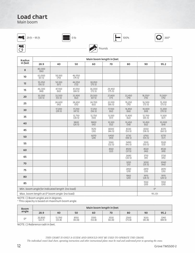
12 Grove TMS500-2
Radius in feet
Main boom length in feet
28.9 40 50 60 70 80 90 95.2
8 80,000 (66)
10 63,000 (61.5)
50,100 (70)
46,950 (74.5)
12 55,050 (56.5)
50,100 (67)
44,950 (72)
38,850 (75.5)
15 46,300 (48)
47,550 (62)
41,050 (68.5)
36,000 (72.5)
29,450 (75.5)
20 30,200 (30.5)
33,500 (53.5)
33,900 (62)
29,500 (67.5)
27,400 (71)
22,450 (74)
18,550* (76)
15,500* (76)
25 24,600 (43)
24,650 (55)
24,700 (62)
23,100 (66.5)
19,250 (70)
16,500 (72.5)
15,300 (73.5)
30 17,200 (29.5)
17,250 (47.5)
17,250 (56.5)
17,550 (62)
16,850 (66)
14,400 (69)
13,200 (70.5)
35 12,750 (38.5)
12,750 (50)
13,100 (57)
13,400 (62)
12,700 (65.5)
11,500 (67)
40 9820 (26.5)
9800 (43)
10,100 (52)
10,450 (58)
10,450 (62)
10,000 (64)
45 7670 (35)
8000 (46.5)
8330 (53.5)
8350 (58.5)
8370 (60.5)
50 6070 (24)
6400 (40)
6730 (48.5)
6760 (54.5)
6770 (57)
55 5160 (32.5)
5490 (43.5)
5510 (50.5)
5520 (53)
60 4160 (22)
4500 (37.5)
4520 (46)
4530 (49)
65 3680 (30.5)
3710 (41)
3720 (45)
70 3010 (21)
3030 (35.5)
3040 (40)
75 2450 (29)
2470 (35)
2470 (35)
80 1960 (20)
1970 (28.5)
1970 (28.5)
85 1550 (20)
1550 (20)
Min. boom angle for indicated length (no load) 0°
Max. boom length at 0° boom angle (no load) 95.2 ft
NOTE: ( ) Boom angles are in degrees.* This capacity is based on maximum boom angle.
Boom angle
Main boom length in feet
28.9 40 50 60 70 80 90 95.2
0° 20,800 (22.7)
13,700 (33.8)
8150 (43.8)
5100 (53.8)
3530 (63.8)
2560 (73.8)
1630 (83.8)
1240 (88.9)
NOTE: ( ) Reference radii in feet.
0 lb 100% 360°
Pounds
29 ft – 95 ft
THIS CHART IS ONLY A GUIDE AND SHOULD NOT BE USED TO OPERATE THE CRANE. The individual crane’s load chart, operating instructions and other instructional plates must be read and understood prior to operating the crane.
Load chartMain boom
13Grove TMS500-2
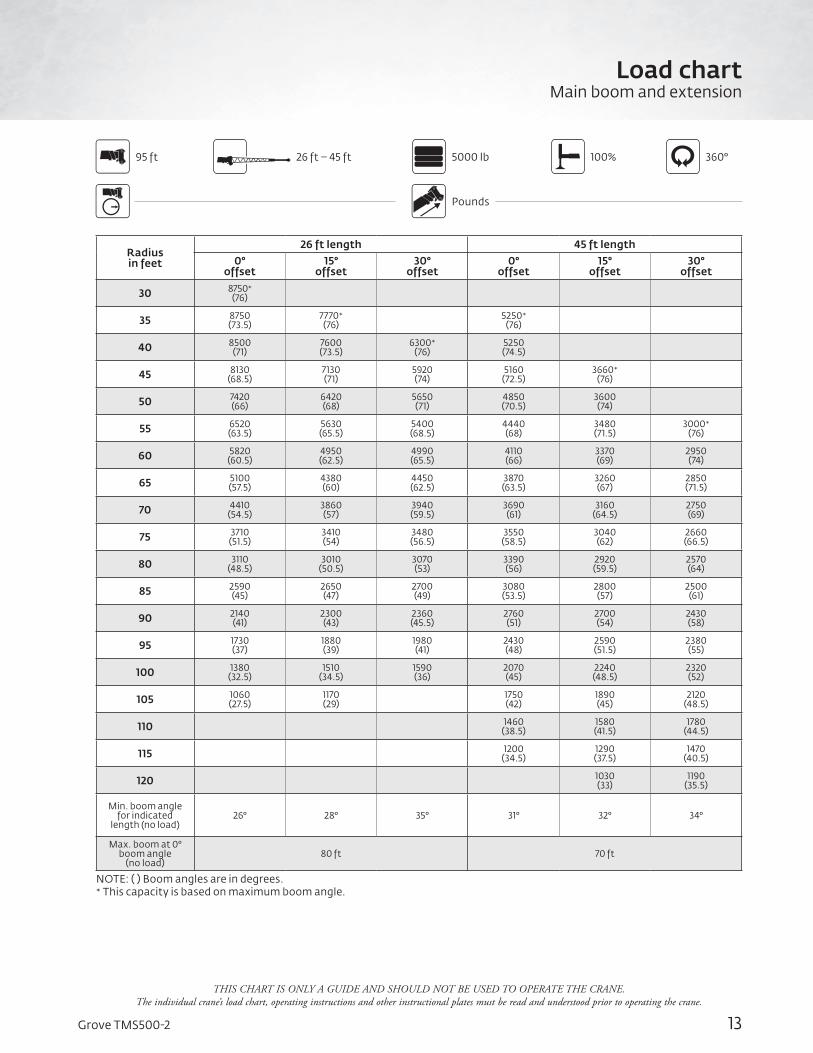
Load chartMain boom and extension
5000 lb 100% 360°26 ft – 45 ft
Pounds
95 ft
THIS CHART IS ONLY A GUIDE AND SHOULD NOT BE USED TO OPERATE THE CRANE. The individual crane’s load chart, operating instructions and other instructional plates must be read and understood prior to operating the crane.
Radius in feet
26 ft length 45 ft length0°
offset15°
offset30°
offset0°
offset15°
offset30°
offset
30 8750* (76)
35 8750 (73.5)
7770* (76)
5250* (76)
40 8500 (71)
7600 (73.5)
6300* (76)
5250 (74.5)
45 8130 (68.5)
7130 (71)
5920 (74)
5160 (72.5)
3660* (76)
50 7420 (66)
6420 (68)
5650 (71)
4850 (70.5)
3600 (74)
55 6520 (63.5)
5630 (65.5)
5400 (68.5)
4440 (68)
3480 (71.5)
3000* (76)
60 5820 (60.5)
4950 (62.5)
4990 (65.5)
4110 (66)
3370 (69)
2950 (74)
65 5100 (57.5)
4380 (60)
4450 (62.5)
3870 (63.5)
3260 (67)
2850 (71.5)
70 4410 (54.5)
3860 (57)
3940 (59.5)
3690 (61)
3160 (64.5)
2750 (69)
75 3710 (51.5)
3410 (54)
3480 (56.5)
3550 (58.5)
3040 (62)
2660 (66.5)
80 3110 (48.5)
3010 (50.5)
3070 (53)
3390 (56)
2920 (59.5)
2570 (64)
85 2590 (45)
2650 (47)
2700 (49)
3080 (53.5)
2800 (57)
2500 (61)
90 2140 (41)
2300 (43)
2360 (45.5)
2760 (51)
2700 (54)
2430 (58)
95 1730 (37)
1880 (39)
1980 (41)
2430 (48)
2590 (51.5)
2380 (55)
100 1380 (32.5)
1510 (34.5)
1590 (36)
2070 (45)
2240 (48.5)
2320 (52)
105 1060 (27.5)
1170 (29)
1750 (42)
1890 (45)
2120 (48.5)
110 1460 (38.5)
1580 (41.5)
1780 (44.5)
115 1200 (34.5)
1290 (37.5)
1470 (40.5)
120 1030 (33)
1190 (35.5)
Min. boom angle for indicated
length (no load)26° 28° 35° 31° 32° 34°
Max. boom at 0° boom angle
(no load)80 ft 70 ft
NOTE: ( ) Boom angles are in degrees. * This capacity is based on maximum boom angle.
14 Grove TMS500-2
Load chartMain boom and extension
8500 lb 100% 360°26 ft – 45 ft
Pounds
29 ft – 95 ft
Radius in feet
26 ft length 45 ft length0°
offset15°
offset30°
offset0°
offset15°
offset30°
offset
30 8750* (76)
35 8750 (73.5)
7770* (76)
5250* (76)
40 8500 (71)
7600 (73.5)
6300* (76)
5250 (74.5)
45 8130 (68.5)
7130 (71)
5920 (74)
5160 (72.5)
3660* (76)
50 7420 (66)
6420 (68)
5650 (71)
4850 (70.5)
3600 (74)
55 6520 (63.5)
5630 (65.5)
5400 (68.5)
4440 (68)
3480 (71.5)
3000* (76)
60 5820 (60.5)
4950 (62.5)
4990 (65.5)
4110 (66)
3370 (69)
2950 (74)
65 5100 (57.5)
4380 (60)
4450 (62.5)
3870 (63.5)
3260 (67)
2850 (71.5)
70 4500 (54.5)
3860 (57)
3940 (59.5)
3690 (61)
3160 (64.5)
2750 (69)
75 3910 (51.5)
3410 (54)
3480 (56.5)
3550 (58.5)
3040 (62)
2660 (66.5)
80 3480 (48.5)
3010 (50.5)
3070 (53)
3390 (56)
2920 (59.5)
2570 (64)
85 3050 (45)
2650 (47)
2700 (49)
3080 (53.5)
2800 (57)
2500 (61)
90 2650 (41)
2330 (43)
2360 (45.5)
2760 (51)
2700 (54)
2430 (58)
95 2310 (37)
2040 (39)
2070 (41)
2470 (48)
2590 (51.5)
2380 (55)
100 2000 (32.5)
1780 (34.5)
1700 (36)
2200 (45)
2360 (48.5)
2320 (52)
105 1690 (27.5)
1510 (29)
1960 (42)
2140 (45)
2210 (48.5)
110 1370 (20.5)
1740 (38.5)
1930 (41.5)
1990 (44.5)
115 1560 (34.5)
1740 (37.5)
1790 (40.5)
120 1440 (30.5)
1470 (33)
1400 (35.5)
125 1240 (25.5)
1280 (28)
130 1040 (18.5)
Min. boom angle for indicated
length (no load)19° 28° 35° 17° 27° 34°
Max. boom at 0° boom angle
(no load)90 ft 80 ft
NOTE: ( ) Boom angles are in degrees. * This capacity is based on maximum boom angle.
THIS CHART IS ONLY A GUIDE AND SHOULD NOT BE USED TO OPERATE THE CRANE. The individual crane’s load chart, operating instructions and other instructional plates must be read and understood prior to operating the crane.
15Grove TMS500-2
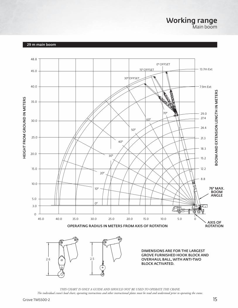
29 m main boom
THIS CHART IS ONLY A GUIDE AND SHOULD NOT BE USED TO OPERATE THE CRANE. The individual crane’s load chart, operating instructions and other instructional plates must be read and understood prior to operating the crane.
Working rangeMain boom
OPERATING RADIUS IN METERS FROM AXIS OF ROTATION
BO
OM
AN
D E
XTE
NSI
ON
LEN
GTH
IN M
ETER
S
HEI
GH
T FR
OM
GR
OU
ND
IN M
ETER
S
76° MAX. BOOM ANGLE
AXIS OFROTATION
DIMENSIONS ARE FOR THE LARGEST GROVE FURNISHED HOOK BLOCK AND OVERHAUL BALL, WITH ANTI-TWO BLOCK ACTIVATED.
5.0
10.0
15.0
20.0
25.0
30.0
40.0
35.0
45.0
3.0
0
48.8
5.010.015.020.035.0 30.0 25.045.0 40.0
10°
0°
30°
40°
50°
60°
70°
20°
30° OFFSET
15° OFFSET
0° OFFSET
29.027.4
24.4
21.3
18.3
15.2
12.2
8.8
7.9m Ext
13.7m Ext
0
2.6 2.5
16 Grove TMS500-2
Load chartMain boom
Radius in meters
Main boom length in meters
8,8 12,2 15,2 18,3 21,3 24,4 27,4 29
2,2 40 000 (67,5)
3 30 000 (61,5)
22 725 (70,5)
21 300 (75)
3,5 25 900 (57,5)
22 725 (68)
20 625 (73)
17 625* (76)
4 23 475 (53,5)
22 725 (65)
19 725 (70,5)
17 125 (74,5)
4,5 21 300 (49)
22 200 (62,5)
18 750 (68,5)
16 425 (72,5)
13 350 (75,5)
5 19 725 (44)
20 975 (59,5)
18 025 (66,5)
15 500 (71)
13 100 (74)
6 16 725 (32)
17 750 (54)
16 650 (62,5)
13 550 (67,5)
12 475 (71,5)
10 175 (74)
8435* (76)
7030* (76)
7 14 700 (47,5)
14 875 (58)
12 100 (64)
11 250 (68,5)
9330 (71,5)
7870 (74)
6975 (75)
8 12 425 (40,5)
12 625 (53,5)
10 825 (60,5)
10 075 (65,5)
8465 (69)
7245 (71,5)
6700 (73)
9 10 675 (31)
10 875 (48)
9745 (57)
9030 (62,5)
7755 (66,5)
6630 (69,5)
6075 (70,5)
10 9300 (17,5)
9475 (42,5)
8890 (53)
8225 (59,5)
7145 (64)
6100 (67)
5555 (68,5)
12 6845 (28)
6840 (44)
6985 (52,5)
6115 (58,5)
5085 (62,5)
4620 (64,5)
14 5165 (33)
5315 (45)
5325 (52,5)
4295 (57,5)
4020 (60)
16 4010 (15,5)
4160 (36,5)
4310 (46)
3745 (52,5)
3420 (55)
18 3315 (24,5)
3465 (38,5)
3210 (47)
2935 (50)
20 2820 (29,5)
2780 (40,5)
2530 (44,5)
22 2310 (15)
2320 (33)
2200 (38)
24 1905 (22,5)
1910 (30)
26 1570 (19,5)
Min. boom angle for indicated length (no load) 0°
Max. boom length at 0° boom angle (no load) 29 m
NOTE: ( ) Boom angles are in degrees.* This capacity is based on maximum boom angle.
Boom angle
Main boom length in meters
8,8 12,2 15,2 18,3 21,3 24,4 27,4 29
0° 11 975 (6,9)
8090 (10,3)
5655 (13,3)
3820 (16,4)
2830 (19,4)
2205 (22,5)
1640 (25,5)
1405 (27,1)
NOTE: ( ) Reference radii in meters.
3900 kg 100% 360°
Meters
8,8 m – 29 m
THIS CHART IS ONLY A GUIDE AND SHOULD NOT BE USED TO OPERATE THE CRANE. The individual crane’s load chart, operating instructions and other instructional plates must be read and understood prior to operating the crane.
17Grove TMS500-2
Radius in meters
Main boom length in meters
8,8 12,2 15,2 18,3 21,3 24,4 27,4 29
2,2 40 000 (67,5)
3 30 000 (61,5)
22 725 (70,5)
21 300 (75)
3,5 25 900 (57,5)
22 725 (68)
20 625 (73)
17 625* (76)
4 23 475 (53,5)
22 725 (65)
19 725 (70,5)
17 125 (74,5)
4,5 21 300 (49)
22 200 (62,5)
18 750 (68,5)
16 425 (72,5)
13 350 (75,5)
5 19 725 (44)
20 975 (59,5)
18 025 (66,5)
15 500 (71)
13 100 (74)
6 16 425 (32)
16 825 (54)
16 650 (62,5)
13 550 (67,5)
12 475 (71,5)
10 175 (74)
8435* (76)
7030* (76)
7 13 900 (47,5)
14 100 (58)
12 100 (64)
11 250 (68,5)
9330 (71,5)
7870 (74)
6975 (75)
8 11 750 (40,5)
11 925 (53,5)
10 825 (60,5)
10 075 (65,5)
8465 (69)
7245 (71,5)
6700 (73)
9 10 050 (31)
10 050 (48)
9745 (57)
9030 (62,5)
7755 (66,5)
6630 (69,5)
6075 (70,5)
10 8285 (17,5)
8285 (42,5)
8290 (53)
8225 (59,5)
7145 (64)
6100 (67)
5555 (68,5)
12 5925 (28)
5920 (44)
6065 (52,5)
6115 (58,5)
5085 (62,5)
4620 (64,5)
14 4410 (33)
4560 (45)
4710 (52,5)
4295 (57,5)
4020 (60)
16 3370 (15,5)
3525 (36,5)
3675 (46)
3680 (52,5)
3420 (55)
18 2760 (24,5)
2915 (38,5)
2920 (47)
2925 (50)
20 2335 (29,5)
2340 (40,5)
2345 (44,5)
22 1875 (15)
1880 (33)
1885 (38)
24 1510 (22,5)
1515 (30)
26 1210 (19,5)
Min. boom angle for indicated length (no load) 0°
Max. boom length at 0° boom angle (no load) 29 m
NOTE: ( ) Boom angles are in degrees.* This capacity is based on maximum boom angle.
Boom angle
Main boom length in meters
8,8 12,2 15,2 18,3 21,3 24,4 27,4 29
0° 11 975 (6,9)
7860 (10,3)
4850 (13,3)
3205 (16,4)
2325 (19,4)
1775 (22,5)
1270 (25,5)
1060 (27,1)
NOTE: ( ) Reference radii in meters.
2300 kg 100% 360°
Meters
8,8 m – 29 m
THIS CHART IS ONLY A GUIDE AND SHOULD NOT BE USED TO OPERATE THE CRANE. The individual crane’s load chart, operating instructions and other instructional plates must be read and understood prior to operating the crane.
Load chartMain boom

18 Grove TMS500-2
Load chartMain boom
Radius in meters
Main boom length in meters
8,8 12,2 15,2 18,3 21,3 24,4 27,4 29
2,2 36 275 (67,5)
3 30 000 (61,5)
22 725 (70,5)
21 300 (75)
3,5 25 900 (57,5)
22 725 (68)
20 625 (73)
17 625* (76)
4 23 475 (53,5)
22 725 (65)
19 725 (70,5)
17 125 (74,5)
4,5 21 300 (49)
21 975 (62,5)
18 750 (68,5)
16 425 (72,5)
13 350 (75,5)
5 18 950 (44)
19 375 (59,5)
18 025 (66,5)
15 500 (71)
13 100 (74)
6 14 350 (32)
15 500 (54)
15 675 (62,5)
13 550 (67,5)
12 475 (71,5)
10 175 (74)
8435* (76)
7030* (76)
7 12 775 (47,5)
12 950 (58)
12 100 (64)
11 250 (68,5)
9330 (71,5)
7870 (74)
6975 (75)
8 10 125 (40,5)
10 150 (53,5)
10 175 (60,5)
10 075 (65,5)
8465 (69)
7245 (71,5)
6700 (73)
9 8060 (31)
8070 (48)
8075 (57)
8225 (62,5)
7755 (66,5)
6630 (69,5)
6075 (70,5)
10 6575 (17,5)
6580 (42,5)
6580 (53)
6730 (59,5)
6875 (64)
6100 (67)
5555 (68,5)
12 4600 (28)
4590 (44)
4740 (52,5)
4890 (58,5)
4900 (62,5)
4620 (64,5)
14 3330 (33)
3480 (45)
3630 (52,5)
3640 (57,5)
3645 (60)
16 2455 (15,5)
2605 (36,5)
2755 (46)
2765 (52,5)
2770 (55)
18 1965 (24,5)
2120 (38,5)
2130 (47)
2135 (50)
20 1630 (29,5)
1640 (40,5)
1645 (44,5)
22 1245 (15)
1255 (33)
1260 (38)
24 945 (22,5)
950 (30)
26 690 (19,5)
Min. boom angle for indicated length (no load) 0°
Max. boom length at 0° boom angle (no load) 29 m
NOTE: ( ) Boom angles are in degrees.* This capacity is based on maximum boom angle.
Boom angle
Main boom length in meters
8,8 12,2 15,2 18,3 21,3 24,4 27,4 29
0° 9455 (6,9)
6215 (10,3)
3695 (13,3)
2315 (16,4)
1600 (19,4)
1160 (22,5)
740 (25,5)
565 (27,1)
NOTE: ( ) Reference radii in meters.
THIS CHART IS ONLY A GUIDE AND SHOULD NOT BE USED TO OPERATE THE CRANE. The individual crane’s load chart, operating instructions and other instructional plates must be read and understood prior to operating the crane.
0 kg 100% 360°
Meters
8,8 m – 29 m
19Grove TMS500-2
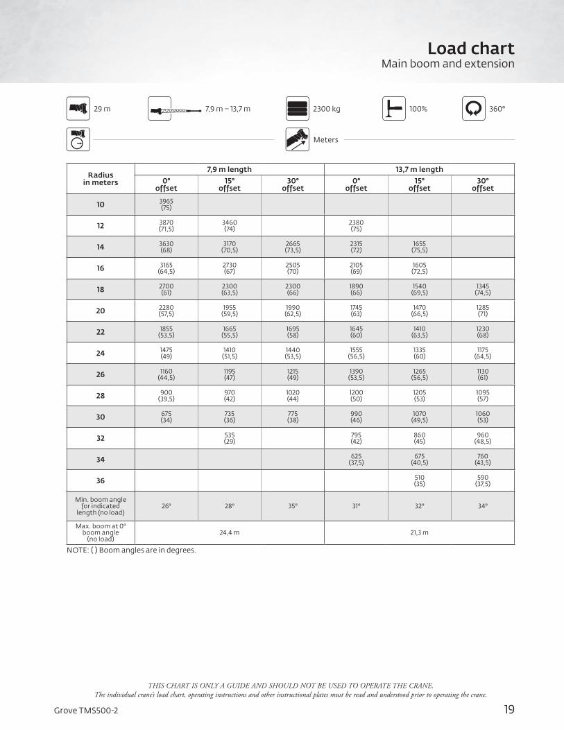
Radius in meters
7,9 m length 13,7 m length0°
offset15°
offset30°
offset0°
offset15°
offset30°
offset
10 3965 (75)
12 3870 (71,5)
3460 (74)
2380 (75)
14 3630 (68)
3170 (70,5)
2665 (73,5)
2315 (72)
1655 (75,5)
16 3165 (64,5)
2730 (67)
2505 (70)
2105 (69)
1605 (72,5)
18 2700 (61)
2300 (63,5)
2300 (66)
1890 (66)
1540 (69,5)
1345 (74,5)
20 2280 (57,5)
1955 (59,5)
1990 (62,5)
1745 (63)
1470 (66,5)
1285 (71)
22 1855 (53,5)
1665 (55,5)
1695 (58)
1645 (60)
1410 (63,5)
1230 (68)
24 1475 (49)
1410 (51,5)
1440 (53,5)
1555 (56,5)
1335 (60)
1175 (64,5)
26 1160 (44,5)
1195 (47)
1215 (49)
1390 (53,5)
1265 (56,5)
1130 (61)
28 900 (39,5)
970 (42)
1020 (44)
1200 (50)
1205 (53)
1095 (57)
30 675 (34)
735 (36)
775 (38)
990 (46)
1070 (49,5)
1060 (53)
32 535 (29)
795 (42)
860 (45)
960 (48,5)
34 625 (37,5)
675 (40,5)
760 (43,5)
36 510 (35)
590 (37,5)
Min. boom angle for indicated
length (no load)26° 28° 35° 31° 32° 34°
Max. boom at 0° boom angle
(no load)24,4 m 21,3 m
NOTE: ( ) Boom angles are in degrees.
2300 kg 100% 360°7,9 m – 13,7 m
Meters
29 m
THIS CHART IS ONLY A GUIDE AND SHOULD NOT BE USED TO OPERATE THE CRANE. The individual crane’s load chart, operating instructions and other instructional plates must be read and understood prior to operating the crane.
Load chartMain boom and extension
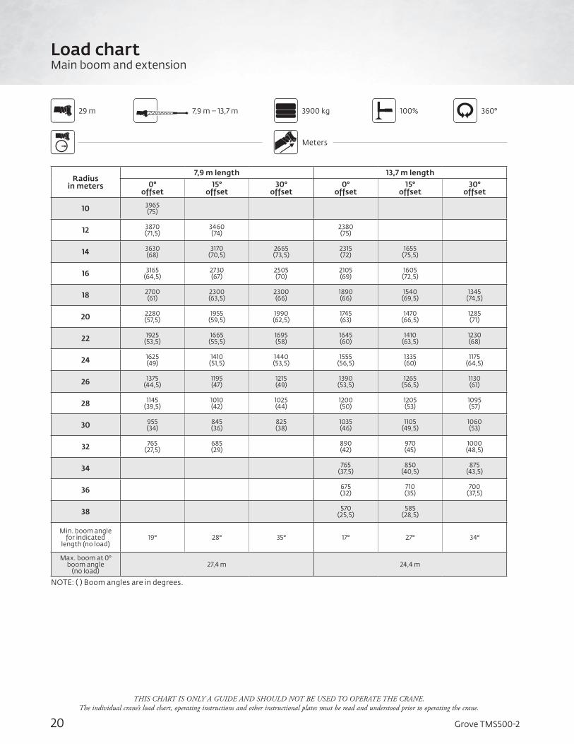
20 Grove TMS500-2
Load chartMain boom and extension
Radius in meters
7,9 m length 13,7 m length0°
offset15°
offset30°
offset0°
offset15°
offset30°
offset
10 3965 (75)
12 3870 (71,5)
3460 (74)
2380 (75)
14 3630 (68)
3170 (70,5)
2665 (73,5)
2315 (72)
1655 (75,5)
16 3165 (64,5)
2730 (67)
2505 (70)
2105 (69)
1605 (72,5)
18 2700 (61)
2300 (63,5)
2300 (66)
1890 (66)
1540 (69,5)
1345 (74,5)
20 2280 (57,5)
1955 (59,5)
1990 (62,5)
1745 (63)
1470 (66,5)
1285 (71)
22 1925 (53,5)
1665 (55,5)
1695 (58)
1645 (60)
1410 (63,5)
1230 (68)
24 1625 (49)
1410 (51,5)
1440 (53,5)
1555 (56,5)
1335 (60)
1175 (64,5)
26 1375 (44,5)
1195 (47)
1215 (49)
1390 (53,5)
1265 (56,5)
1130 (61)
28 1145 (39,5)
1010 (42)
1025 (44)
1200 (50)
1205 (53)
1095 (57)
30 955 (34)
845 (36)
825 (38)
1035 (46)
1105 (49,5)
1060 (53)
32 765 (27,5)
685 (29)
890 (42)
970 (45)
1000 (48,5)
34 765 (37,5)
850 (40,5)
875 (43,5)
36 675 (32)
710 (35)
700 (37,5)
38 570 (25,5)
585 (28,5)
Min. boom angle for indicated
length (no load)19° 28° 35° 17° 27° 34°
Max. boom at 0° boom angle
(no load)27,4 m 24,4 m
NOTE: ( ) Boom angles are in degrees.
3900 kg 100% 360°7,9 m – 13,7 m
Meters
29 m
THIS CHART IS ONLY A GUIDE AND SHOULD NOT BE USED TO OPERATE THE CRANE. The individual crane’s load chart, operating instructions and other instructional plates must be read and understood prior to operating the crane.
21Grove TMS500-2
THIS CHART IS ONLY A GUIDE AND SHOULD NOT BE USED TO OPERATE THE CRANE. The individual crane’s load chart, operating instructions and other instructional plates must be read and understood prior to operating the crane.
102 ft main boom
OPERATING RADIUS IN FEET FROM AXIS OF ROTATION
BO
OM
AN
D E
XTE
NSI
ON
LEN
GTH
IN F
EET
HEI
GH
T FR
OM
GR
OU
ND
IN F
EET
21
Working rangeMain boom
DIMENSIONS ARE FOR THE LARGEST GROVE FURNISHED HOOK BLOCK AND OVERHAUL BALL, WITH ANTI-TWO BLOCK ACTIVATED.
76° MAX. BOOM ANGLE
AXIS OFROTATION
20
30
40
50
60
70
80
90
100
110
120
140
130
150
10
0
160
102030506070 40130 120 110 100 90 80150 140
10°
0°
30°
40°
50°
60°
70°
20°
30° OFFSET
15° OFFSET
0° OFFSET
101.7'
90.0'
80.0'
70.0'
60.0'
50.0'
40.0'
32.3'
26' Ext
45' Ext
0
8' 8" 8' 2"
22 Grove TMS500-2
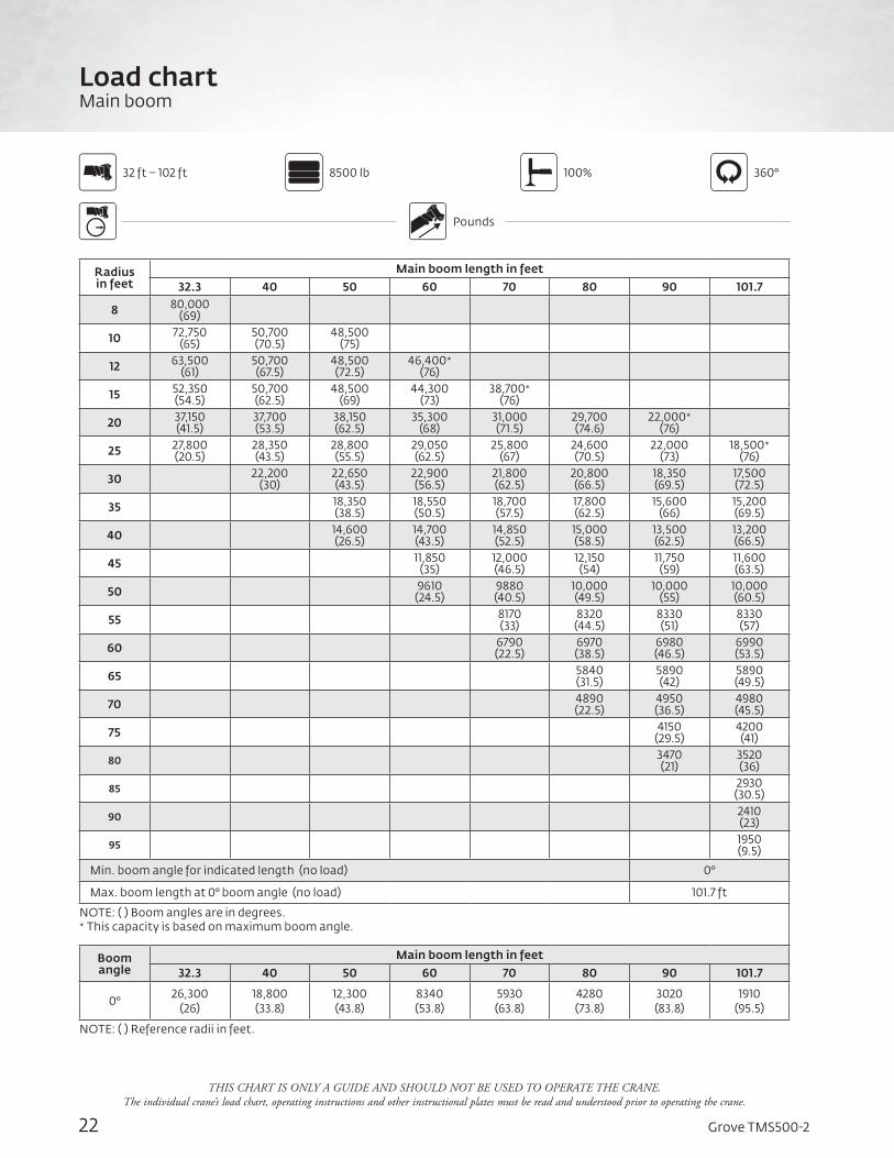
Load chartMain boom
8500 lb 100% 360°
Pounds
32 ft – 102 ft
Radius in feet
Main boom length in feet32.3 40 50 60 70 80 90 101.7
8 80,000(69)
10 72,750(65)
50,700(70.5)
48,500(75)
12 63,500(61)
50,700(67.5)
48,500(72.5)
46,400*(76)
15 52,350(54.5)
50,700(62.5)
48,500(69)
44,300(73)
38,700*(76)
20 37,150(41.5)
37,700(53.5)
38,150(62.5)
35,300(68)
31,000(71.5)
29,700(74.6)
22,000*(76)
25 27,800(20.5)
28,350(43.5)
28,800(55.5)
29,050(62.5)
25,800(67)
24,600(70.5)
22,000(73)
18,500*(76)
30 22,200(30)
22,650(43.5)
22,900(56.5)
21,800(62.5)
20,800(66.5)
18,350(69.5)
17,500(72.5)
35 18,350(38.5)
18,550(50.5)
18,700(57.5)
17,800(62.5)
15,600(66)
15,200(69.5)
40 14,600 (26.5)
14,700(43.5)
14,850(52.5)
15,000(58.5)
13,500(62.5)
13,200(66.5)
45 11,850(35)
12,000(46.5)
12,150(54)
11,750(59)
11,600(63.5)
50 9610(24.5)
9880(40.5)
10,000(49.5)
10,000(55)
10,000(60.5)
55 8170(33)
8320(44.5)
8330(51)
8330(57)
60 6790(22.5)
6970 (38.5)
6980(46.5)
6990(53.5)
65 5840(31.5)
5890(42)
5890(49.5)
70 4890(22.5)
4950(36.5)
4980(45.5)
75 4150(29.5)
4200(41)
80 3470(21)
3520(36)
85 2930(30.5)
90 2410(23)
95 1950(9.5)
Min. boom angle for indicated length (no load) 0°
Max. boom length at 0° boom angle (no load) 101.7 ft
NOTE: ( ) Boom angles are in degrees. * This capacity is based on maximum boom angle.
Boom angle
Main boom length in feet32.3 40 50 60 70 80 90 101.7
0° 26,300(26)
18,800(33.8)
12,300(43.8)
8340(53.8)
5930(63.8)
4280(73.8)
3020(83.8)
1910(95.5)
NOTE: ( ) Reference radii in feet.
THIS CHART IS ONLY A GUIDE AND SHOULD NOT BE USED TO OPERATE THE CRANE. The individual crane’s load chart, operating instructions and other instructional plates must be read and understood prior to operating the crane.
23Grove TMS500-2
THIS CHART IS ONLY A GUIDE AND SHOULD NOT BE USED TO OPERATE THE CRANE. The individual crane’s load chart, operating instructions and other instructional plates must be read and understood prior to operating the crane.
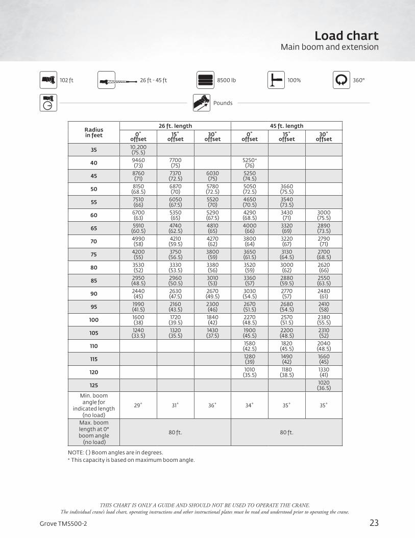
Load chartMain boom and extension
8500 lb 100% 360°
Pounds
102 ft
Radius in feet
26 ft. length 45 ft. length0˚
offset15˚
offset30˚
offset0˚
offset15˚
offset30˚
offset
35 10,200(75.5)
40 9460(73)
7700(75)
5250*(76)
45 8760(71)
7370(72.5)
6030(75)
5250(74.5)
50 8150(68.5)
6870(70)
5780(72.5)
5050(72.5)
3660(75.5)
55 7510(66)
6050(67.5)
5520(70)
4650(70.5)
3540(73.5)
60 6700(63)
5350(65)
5290(67.5)
4290(68.5)
3430(71)
3000(75.5)
65 5910(60.5)
4740(62.5)
4810(65)
4000(66)
3320(69)
2890(73.5)
70 4990(58)
4210(59.5)
4270(62)
3800(64)
3220(67)
2790(71)
75 4200(55)
3750(56.5)
3800 (59)
3650(61.5)
3130(64.5)
2700(68.5)
80 3530(52)
3330(53.5)
3380(56)
3520(59)
3000(62)
2620(66)
85 2950(48.5)
2960(50.5)
3010(53)
3360(57)
2880(59.5)
2550(63.5)
90 2440(45)
2630(47.5)
2670(49.5)
3030(54.5)
2770(57)
2480(61)
95 1990(41.5)
2160(43.5)
2300(46)
2670(51.5)
2680(54.5)
2410 (58)
100 1600(38)
1720(39.5)
1840(42)
2270(48.5)
2570(51.5)
2380(55.5)
105 1240(33.5)
1320(35.5)
1430(37.5)
1900(45.5)
2200(48.5)
2310(52)
110 1580(42.5)
1820(45.5)
2040(48.5)
115 1280(39)
1490(42)
1660(45)
120 1010(35.5)
1180(38.5)
1330(41)
125 1020(36.5)
Min. boom angle for
indicated length (no load)
29˚ 31˚ 36˚ 34˚ 35˚ 35˚
Max. boom length at 0° boom angle
(no load)
80 ft. 80 ft.
NOTE: ( ) Boom angles are in degrees. * This capacity is based on maximum boom angle.
26 ft - 45 ft
24 Grove TMS500-2
Working rangeMain boom
31 m main boom
THIS CHART IS ONLY A GUIDE AND SHOULD NOT BE USED TO OPERATE THE CRANE. The individual crane’s load chart, operating instructions and other instructional plates must be read and understood prior to operating the crane.
OPERATING RADIUS IN METERS FROM AXIS OF ROTATION
BO
OM
AN
D E
XTE
NSI
ON
LEN
GTH
IN M
ETER
S
HEI
GH
T FR
OM
GR
OU
ND
IN M
ETER
S
76° MAX. BOOM ANGLE
AXIS OFROTATION
DIMENSIONS ARE FOR THE LARGEST GROVE FURNISHED HOOK BLOCK AND OVERHAUL BALL, WITH ANTI-TWO BLOCK ACTIVATED.
5.0
10.0
15.0
20.0
25.0
30.0
40.0
35.0
45.0
3.0
0
48.8
5.0 3.010.015.020.035.0 30.0 25.045.0 40.0
10°
0°
30°
40°
50°
60°70°
20°
30° OFFSET
15° OFFSET
0° OFFSET
31.0
27.4
24.4
21.3
18.3
15.2
12.2
9.8
7.9 Ext
13.7 Ext
0
2.6m 2.5m
25Grove TMS500-2
Load chartMain boom
Radius in meters
Main boom length in meters
9,8 12,2 15,2 18,3 21,3 24,4 27,4 31
2,2 40 000 (71)
3 32 725 (65,5)
22 975 (71)
21 975 (75,5)
3,5 29 875 (62)
22 975 (68,5)
21 975 (73,5)
4 27 350 (58,5)
22 975 (65,5)
21 975 (71,5)
21 025 (75)
4,5 24 175 (55)
22 975 (63)
21 975 (69,5)
20 150 (73,5)
5 21 425 (51)
21 675 (60)
21 025 (67)
18 925 (71,5)
17 550 (75)
6 17 200 (42,5)
17 450 (54)
17 650 (63)
16 250 (68)
14 275 (72)
13 450 (74,5)
7 14 100 (31)
14 350 (47,5)
14 575 (58,5)
14 400 (64,5)
12 650 (69)
12 075 (72)
9975 (74,5)
8 12 075 (40,5)
12 275 (53,5)
12 375 (61)
11 250 (66)
10 725 (69,5)
9530 (72,5)
8375 (74,5)
9 10 300 (31,5)
10 500 (48,5)
10 625 (57)
10 025 (63)
9585 (67)
8470 (70)
7980 (72,5)
10 8905 (17,5)
9115 (43)
9220 (53)
9045 (60)
8625 (64,5)
7625 (67,5)
7350 (71)
12 6825 (28,5)
6875 (44,5)
6945 (53)
7015 (59)
6245 (63)
6100 (67)
14 5170 (33,5)
5250 (45,5)
5310 (53)
5220 (58,5)
5140 (63)
16 3970 (16)
4070 (37)
4135 (47)
4135 (53)
4140 (58,5)
18 3190 (25)
3270 (39,5)
3275 (47,5)
3275 (54)
20 2590 (30,5)
2615 (41)
2615 (49)
22 2055 (15,5)
2080 (33,5)
2100 (43,5)
24 1645 (23,5)
1670 (37,5)
26 1310 (30)
28 1010 (19,5)
Min. boom angle for indicated length (no load) 0°
Max. boom length at 0° boom angle (no load) 31 m
NOTE: ( ) Boom angles are in degrees.
Boom angle
Main boom length in meters
9,8 12,2 15,2 18,3 21,3 24,4 27,4 31
0° 11 925 (7,9)
8540 (10,3)
5590 (13,3)
3785 (16,4)
2690 (19,4)
1945 (22,5)
1370 (25,5)
865 (29,1)
NOTE: ( ) Reference radii in meters.
THIS CHART IS ONLY A GUIDE AND SHOULD NOT BE USED TO OPERATE THE CRANE. The individual crane’s load chart, operating instructions and other instructional plates must be read and understood prior to operating the crane.
3900 kg 100% 360°
Meters
9,8 m – 31 m
26 Grove TMS500-2
Load chartMain boom and extension
Radius in meters
7,9 m length 13,7 m length0°
offset15°
offset30°
offset0°
offset15°
offset30°
offset
12 4335 (73,5)
3525 (75,5)
14 3925 (70,5)
3300 (72)
2735 (75)
2360 (74,5)
16 3550 (67)
2930 (69)
2565 (71,5)
2200 (71,5)
1630 (74,5)
18 3105 (63,5)
2485 (65,5)
2420 (68)
1975 (69)
1565 (71,5)
1360 (76)
20 2625 (60)
2120 (62)
2150 (64,5)
1800 (66)
1500 (68,5)
1305 (73)
22 2100 (56,5)
1820 (58,5)
1845 (60,5)
1690 (63)
1440 (65,5)
1250 (70)
24 1675 (52,5)
1560 (54,5)
1580 (57)
1610 (60)
1375 (62,5)
1200 (66,5)
26 1325 (48,5)
1335 (50,5)
1355 (52,5)
1515 (56,5)
1305 (59,5)
1155 (63,5)
28 1030 (44)
1115 (46)
1155 (48,5)
1320 (53,5)
1240 (56)
1115 (60)
30 780 (39)
840 (41)
900 (43,5)
1085 (49,5)
1180 (52,5)
1085 (56)
32 565 (33,5)
600 (35,5)
650 (37,5)
865 (45,5)
995 (48,5)
1045 (52)
34 670 (41,5)
780 (44,5)
870 (47,5)
36 500 (37)
585 (40)
660 (42,5)
Min. boom angle for indicated
length (no load)29° 31° 36° 34° 35° 35°
Max. boom at 0° boom angle
(no load)24,4 m 24,4 m
NOTE: ( ) Boom angles are in degrees.
3900 kg 100% 360°7,9 m – 13,7 m
Meters
31 m
THIS CHART IS ONLY A GUIDE AND SHOULD NOT BE USED TO OPERATE THE CRANE. The individual crane’s load chart, operating instructions and other instructional plates must be read and understood prior to operating the crane.
27Grove TMS500-2 *Denotes optional equipment
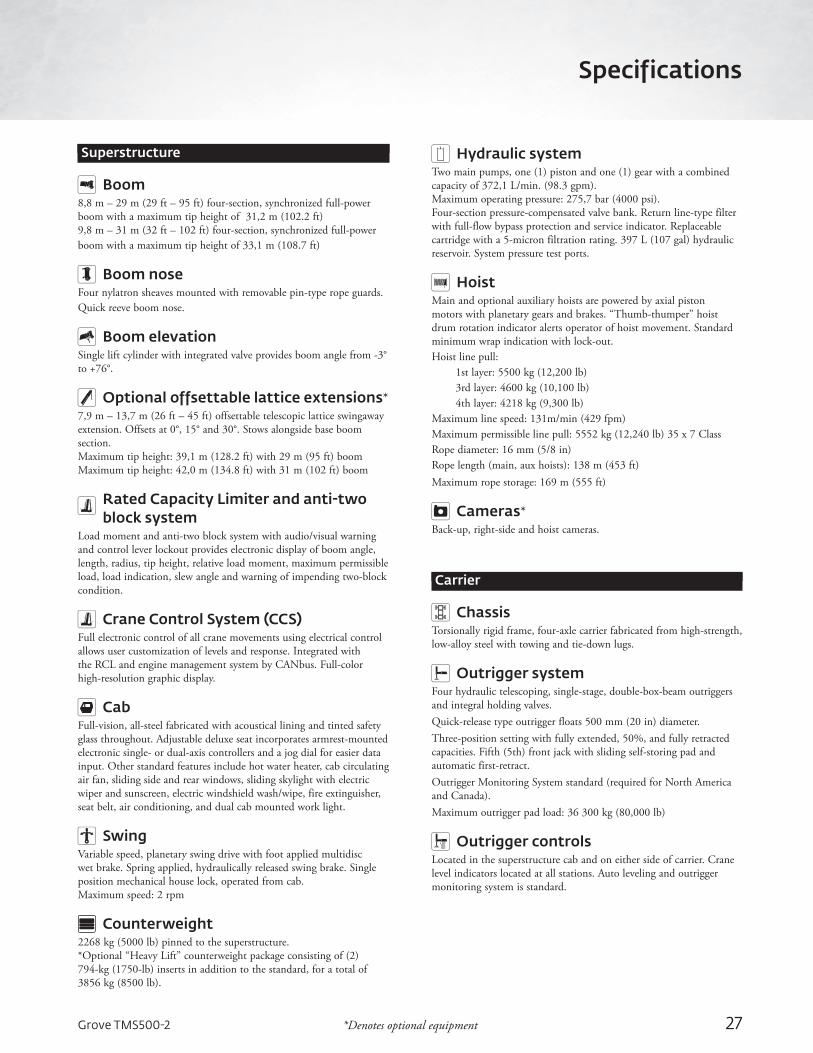
Superstructure
Boom8,8 m – 29 m (29 ft – 95 ft) four-section, synchronized full-power boom with a maximum tip height of 31,2 m (102.2 ft)9,8 m – 31 m (32 ft – 102 ft) four-section, synchronized full-power boom with a maximum tip height of 33,1 m (108.7 ft)
Boom noseFour nylatron sheaves mounted with removable pin-type rope guards. Quick reeve boom nose.
Boom elevationSingle lift cylinder with integrated valve provides boom angle from -3° to +76°.
Optional offsettable lattice extensions*7,9 m – 13,7 m (26 ft – 45 ft) offsettable telescopic lattice swingaway extension. Offsets at 0°, 15° and 30°. Stows alongside base boom section. Maximum tip height: 39,1 m (128.2 ft) with 29 m (95 ft) boomMaximum tip height: 42,0 m (134.8 ft) with 31 m (102 ft) boom
Rated Capacity Limiter and anti-two block system
Load moment and anti-two block system with audio/visual warning and control lever lockout provides electronic display of boom angle, length, radius, tip height, relative load moment, maximum permissible load, load indication, slew angle and warning of impending two-block condition.
Crane Control System (CCS)Full electronic control of all crane movements using electrical control allows user customization of levels and response. Integrated with the RCL and engine management system by CANbus. Full-color high-resolution graphic display.
CabFull-vision, all-steel fabricated with acoustical lining and tinted safety glass throughout. Adjustable deluxe seat incorporates armrest-mounted electronic single- or dual-axis controllers and a jog dial for easier data input. Other standard features include hot water heater, cab circulating air fan, sliding side and rear windows, sliding skylight with electric wiper and sunscreen, electric windshield wash/wipe, fire extinguisher, seat belt, air conditioning, and dual cab mounted work light.
SwingVariable speed, planetary swing drive with foot applied multidisc wet brake. Spring applied, hydraulically released swing brake. Single position mechanical house lock, operated from cab.Maximum speed: 2 rpm
Counterweight2268 kg (5000 lb) pinned to the superstructure.*Optional “Heavy Lift” counterweight package consisting of (2) 794-kg (1750-lb) inserts in addition to the standard, for a total of 3856 kg (8500 lb).
Hydraulic systemTwo main pumps, one (1) piston and one (1) gear with a combined capacity of 372,1 L/min. (98.3 gpm). Maximum operating pressure: 275,7 bar (4000 psi). Four-section pressure-compensated valve bank. Return line-type filter with full-flow bypass protection and service indicator. Replaceable cartridge with a 5-micron filtration rating. 397 L (107 gal) hydraulic reservoir. System pressure test ports.
HoistMain and optional auxiliary hoists are powered by axial piston motors with planetary gears and brakes. “Thumb-thumper” hoist drum rotation indicator alerts operator of hoist movement. Standard minimum wrap indication with lock-out.Hoist line pull:
1st layer: 5500 kg (12,200 lb)3rd layer: 4600 kg (10,100 lb)4th layer: 4218 kg (9,300 lb)
Maximum line speed: 131m/min (429 fpm)Maximum permissible line pull: 5552 kg (12,240 lb) 35 x 7 ClassRope diameter: 16 mm (5/8 in)Rope length (main, aux hoists): 138 m (453 ft)Maximum rope storage: 169 m (555 ft)
Cameras*Back-up, right-side and hoist cameras.
Carrier
ChassisTorsionally rigid frame, four-axle carrier fabricated from high-strength, low-alloy steel with towing and tie-down lugs.
Outrigger systemFour hydraulic telescoping, single-stage, double-box-beam outriggers and integral holding valves.Quick-release type outrigger floats 500 mm (20 in) diameter.Three-position setting with fully extended, 50%, and fully retracted capacities. Fifth (5th) front jack with sliding self-storing pad and automatic first-retract.Outrigger Monitoring System standard (required for North America and Canada).Maximum outrigger pad load: 36 300 kg (80,000 lb)
Outrigger controlsLocated in the superstructure cab and on either side of carrier. Crane level indicators located at all stations. Auto leveling and outrigger monitoring system is standard.
Specifications
28
Engine Cummins ISL9 six-cylinder, turbocharged and after-cooled diesel engine. 9 L 261 kW (350 bhp) at 2000 rpm. Maximum torque 1159 Nm (1150 lb-ft) at 1400 rpm. “On Highway” EPA, CARB compliant.Equipped with engine compression brake, ether start aid and 110 V block heater.Fuel requirement: Maximum of 15 ppm sulfur content (Ultra Low Sulfur Diesel). Diesel exhaust fluid required.
Fuel tank capacity244 L (64.5 gal)
TransmissionEaton Fuller Ultrashift® PLUS Transmission: 11 speeds forward, 3 reverse, automated.
SteeringFront-axle, single-circuit, mechanical steering with hydraulic power assist. Turning radius: 10,8 m (35.6 ft).
AxlesFront: (1) tube-type steering axle, 2,34 m (92.29 in) track.Rear: (2) single reduction drive axles, 1,85 m (73.0 in) track. Inter-axle differential locks.Drive: 6 x 4 x 2 in
BrakesS-cam, dual air split system operating on all wheels. Spring-applied, air-released parking brake acting on rear axles. Air dryer. ABS with traction control.
SuspensionFront: Multi-leaf spring.Rear: Walking beam with air bags and shock absorbers.
TiresFront: 425/65R22.5 tubeless, mounted on aluminum disc wheels.Rear: 11R22.5 tubeless, mounted on aluminum disc wheels.
LightsLighting package including turn indicators; head, tail, brake and hazard warning lights.
CabSingle-driver design, aluminum fabricated with acoustical lining and tinted safety glass. Air conditioning. Fabric-covered seat with air adjustment. Driving controls and engine instrumentation including tilt telescope multifunction steering wheel, tachometer, speedometer, trip meter, voltmeter, water temp., oil, fuel level, air pressure gauge, engine high temp./low oil pressure A/V warning. Other standard items include display for back-up and passenger side cameras, hot water heater/defroster, electric windshield wash/wipe, fire extinguisher, wireless rigging remote with battery charging station, seat belt and door lock.
Electrical systemTwo (2) maintenance-free batteries provide 24 V electrical system. Standard lockable battery disconnect.
Maximum speed105 kph (65 mph)
Gradeability (theoretical)79.7%, 1st gear
Miscellaneous standard equipmentAluminum fenders; dual rear view mirrors; electronic back-up alarm; two sling/tool boxes; tire inflation kit; air cleaner restriction indicator; headache ball and hook block stowage trays; air conditioning; air horn; hoist access platform
Optional equipment*• 360° mechanical swing lock• Aluminum outrigger pads• Auxiliary hoist package includes Model HP15C-17G auxiliary hoist
with electronic hoist drum rotation indicator, hoist drum cable follower, hoist mirror, 137 m (450 ft) of 16 mm (5/8 in) 35 x 7 class wire rope and auxiliary single-sheave boom nose.
• Auxiliary lighting package includes carrier cab and superstructure-mounted amber flashing beacons, dual base boom-mounted floodlights, in-cab RCL light bar.
• Bluetooth/AM/FM radios• Counterweight package• CraneSTAR asset management system• Cross axle differential locks• Hook blocks• Pintle hook (rear)• Single-axis joysticks• Vertical RCL light tower• Wind speed indicator• Winterfront radiator cover• Wireless rigging remote control• 610 mm (24 x 24 x 24) in toolbox
*Denotes optional equipment
Specifications
Grove TMS500-2
29Grove TMS500-2
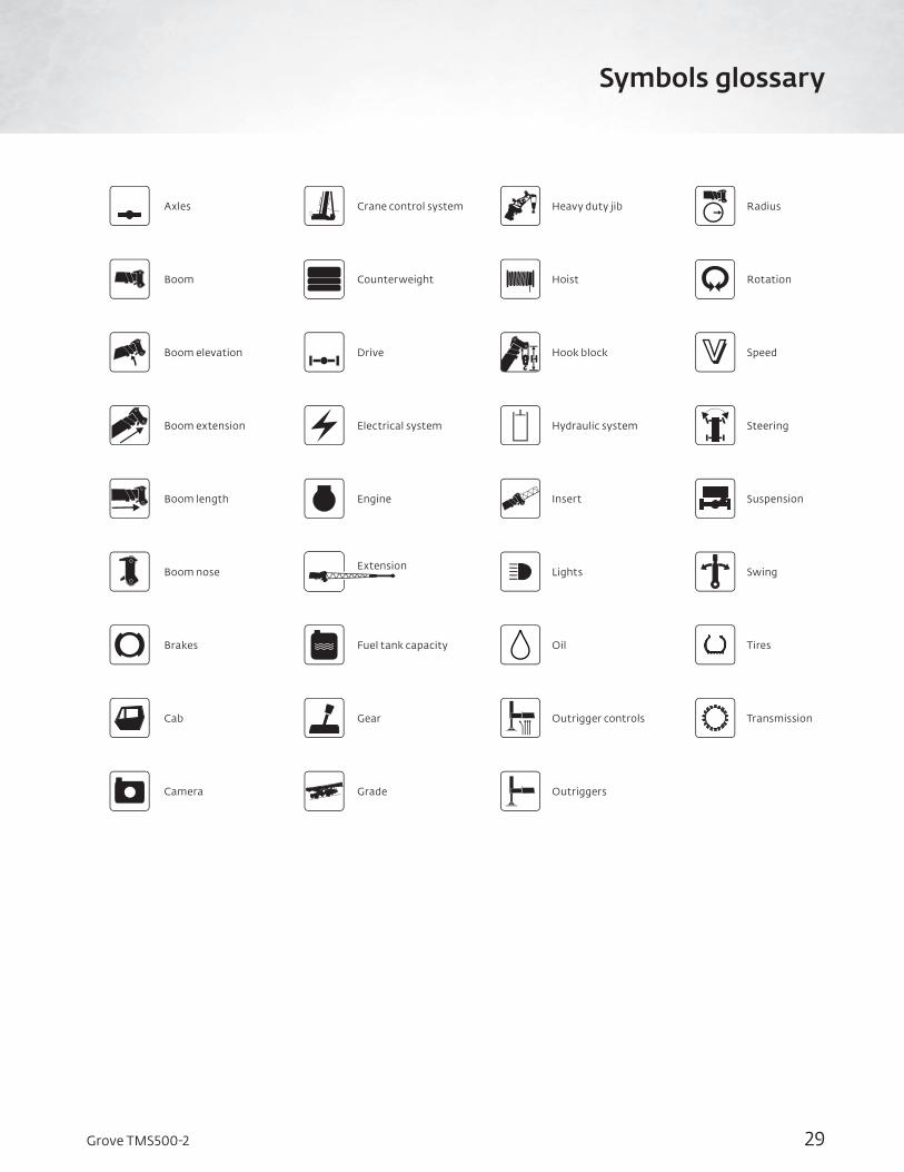
Symbols glossary
Transmission
Speed
Tires
Radius
Rotation
Steering
Suspension
Swing
Outrigger controls
Hook block
Oil
Heavy duty jib
Hoist
Hydraulic system
Insert
Lights
Outriggers
Cab
Boom elevation
Brakes
Axles
Boom
Boom extension
Boom length
Boom nose
Camera
Gear
Drive
Fuel tank capacity
Crane control system
Counterweight
Electrical system
Engine
Extension
Grade

30 Grove TMS500-2
Notes

31Grove TMS500-2
Notes
www.manitowoc.com
This document is non-contractual. Constant improvement and engineering progress make it necessary that we reserve the right to make specification, equipment, and price changes without notice. Illustrations shown may include optional equipment and accessories and may not include all standard equipment.
©2019 The Manitowoc Company, Inc.Form No. TMS500-2 PGPart No. 19-005/1M/0719
ChinaShanghai, China Tel: +86 21 6457 0066
Middle East and Greater Asia-Pacific Singapore Tel: +65 6264 1188
Dubai, UAETel: +971 4 8862677
Europe, Middle East, Africa Dardilly, France - TOWERSTel: +33 (0)4 72 18 20 20
Wilhelmshaven, Germany - MOBILETel: +49 (0) 4421 294 0
Americas Manitowoc, Wisconsin, USA Tel: +1 920 684 4410
Shady Grove, Pennsylvania, USA Tel: +1 717 597 8121
Manitowoc Cranes
Regional headquarters