Embed Size (px)
Citation preview

#20 Setting Tool Assembly Product Family No. 41‐21(20)
TECHNICAL UNIT
Page 1 ‐ Revised 01/10/10
BRICO OIL TOOLS provides a dependable line of Wireline Pressure Setting Tools for the Wireline industry worldwide. Our engineering, high quality and service provides a cost effective Alternative. BT #20 Introduction The BT #20 Setting Tool Assembly is devised for setting of equipment in the well bore on electric Wireline. Products of combustion are utilized for the gradual development of force through pressure thus hydraulic force is transferred through the tool, through the Wireline Adapter Kit to a packer, bridge plugs, cement retainers, frac plugs to fully set the slips and pack off the sealing element of these products. This motive force operates the various working parts of the BT# 20 setting tool in a proper sequence to ensure a force in excess of 60,000 lbs. / 26.6 daN. The tool may be used in multiple tasks on highly deviated well bores via a well bore tractor, e-coil and can incorporate a casing collar for depth correlation. A wide range of firing head adapters and Wireline accessories are available from BRICO Oil Tools. The high pressure required within the tool is built up through the burning of a Slow Set Power Charge, or a Standard Power Charge. For specifics on all Power Charges and Igniters refer to BRICO Tech info on Power Charges and Igniters Manuals. The setting pressure is confined to the proper area of the setting tool through the use of o-ring seals or chevron seals on the high temperature tool. It is of extreme importance that all of these o-rings and seals be maintained in perfect condition and all tool internals are completely cleaned prior to assembly. The standard BT #20 Setting Tool Assembly incorporates a Disk Bleeder Valve to provide a safe, easy method of bleeding off trapped pressure from inside the tool after it has been run and before being back loaded for transport. The tool should be bled off once the tool has been pulled from the well bore. This tool should never be transported without the tool pressure released or bled off. Pressure Features / Benefits at Setting Depth
Use to set Bridge Plugs, Cement Retainers, and Production Packers on Electric Wireline.
Use in conjunction with a Casing Collar Locator for correlation of exact setting depth.
Uses the advantage of the fast running capability of Wireline.
Proven design has been the “Industry Standard “.
BT# 20 size tool for setting equipment inside 5” / 127mm tubing / casing up to 30” / 762mm casing.
#20 Setting Tool Assembly Product Family No. 41‐21(20)
TECHNICAL UNIT
Page 2 ‐ Revised 01/10/10
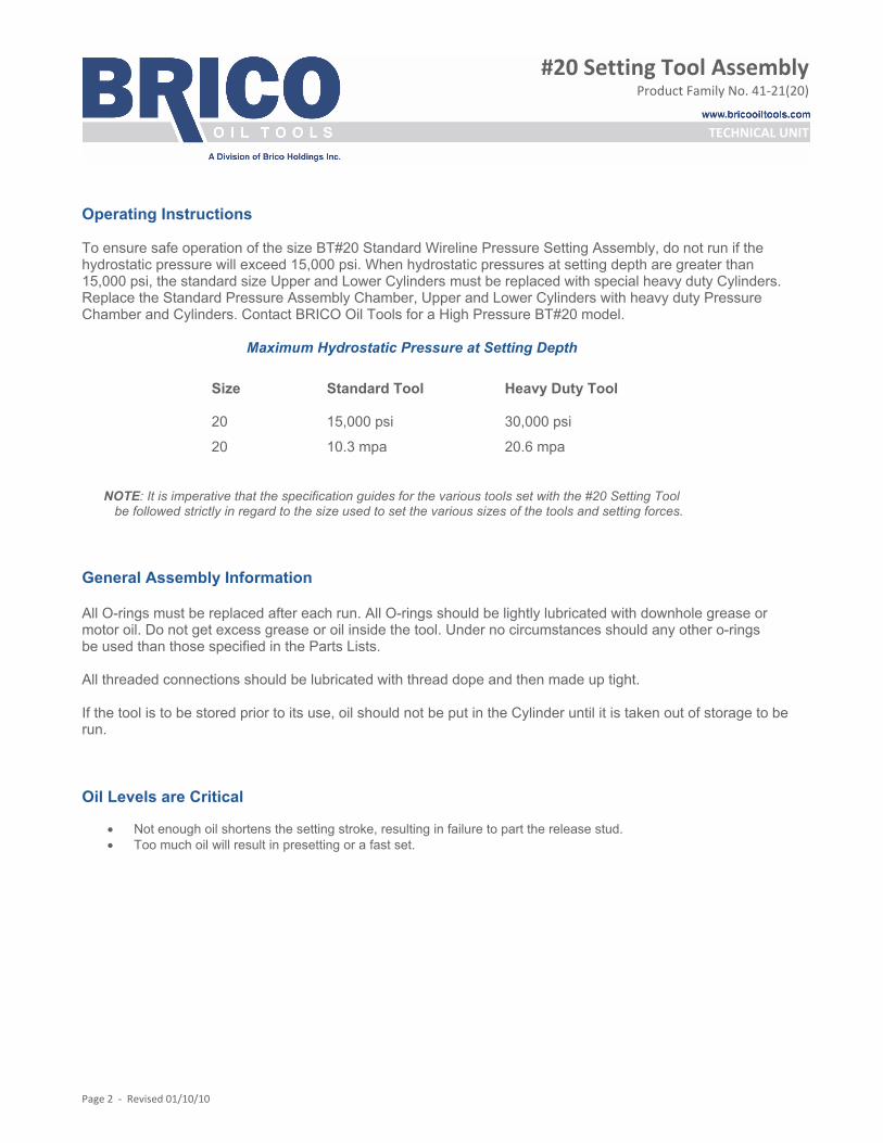
Operating Instructions To ensure safe operation of the size BT#20 Standard Wireline Pressure Setting Assembly, do not run if the hydrostatic pressure will exceed 15,000 psi. When hydrostatic pressures at setting depth are greater than 15,000 psi, the standard size Upper and Lower Cylinders must be replaced with special heavy duty Cylinders. Replace the Standard Pressure Assembly Chamber, Upper and Lower Cylinders with heavy duty Pressure Chamber and Cylinders. Contact BRICO Oil Tools for a High Pressure BT#20 model. Maximum Hydrostatic Pressure at Setting Depth NOTE: It is imperative that the specification guides for the various tools set with the #20 Setting Tool be followed strictly in regard to the size used to set the various sizes of the tools and setting forces. General Assembly Information All O-rings must be replaced after each run. All O-rings should be lightly lubricated with downhole grease or motor oil. Do not get excess grease or oil inside the tool. Under no circumstances should any other o-rings be used than those specified in the Parts Lists. All threaded connections should be lubricated with thread dope and then made up tight. If the tool is to be stored prior to its use, oil should not be put in the Cylinder until it is taken out of storage to be run. Oil Levels are Critical
Not enough oil shortens the setting stroke, resulting in failure to part the release stud. Too much oil will result in presetting or a fast set.
Size Standard Tool
Heavy Duty Tool
20 15,000 psi 30,000 psi
20 10.3 mpa 20.6 mpa

#20 Setting Tool Assembly Product Family No. 41‐21(20)
TECHNICAL UNIT
Page 3 ‐ Revised 01/10/10
Instructions Invert cylinder and push Piston to bottom, using wooden dowel. Fill cylinder with oil to level “A” as shown in chart according to maximum well temperature expected on run.
*Dimension “A” - Distance from cylinder to oil level
Oil Level Filling Information Oil Any medium to light weight petroleum based motor oil or hydraulic oil may be used in the BRICO BT#20 Setting Tools. This includes all motor oils between 5W and 30W, automotive transmission fluid or high temperature hydraulic oil. BRICO Oil Tools recommends the use of automatic transmission fluid.
Temperature
Dimension “A” (Inches/MM)* BT#20 MM
200oF or Less 4 101.6
201oF – 275oF 4 ½ 114.3
276oF – 350oF 5 127
351oF – 400oF 5 ½ 139.7
#20 Setting Tool Assembly Product Family No. 41‐21(20)
TECHNICAL UNIT
Page 4 ‐ Revised 01/10/10
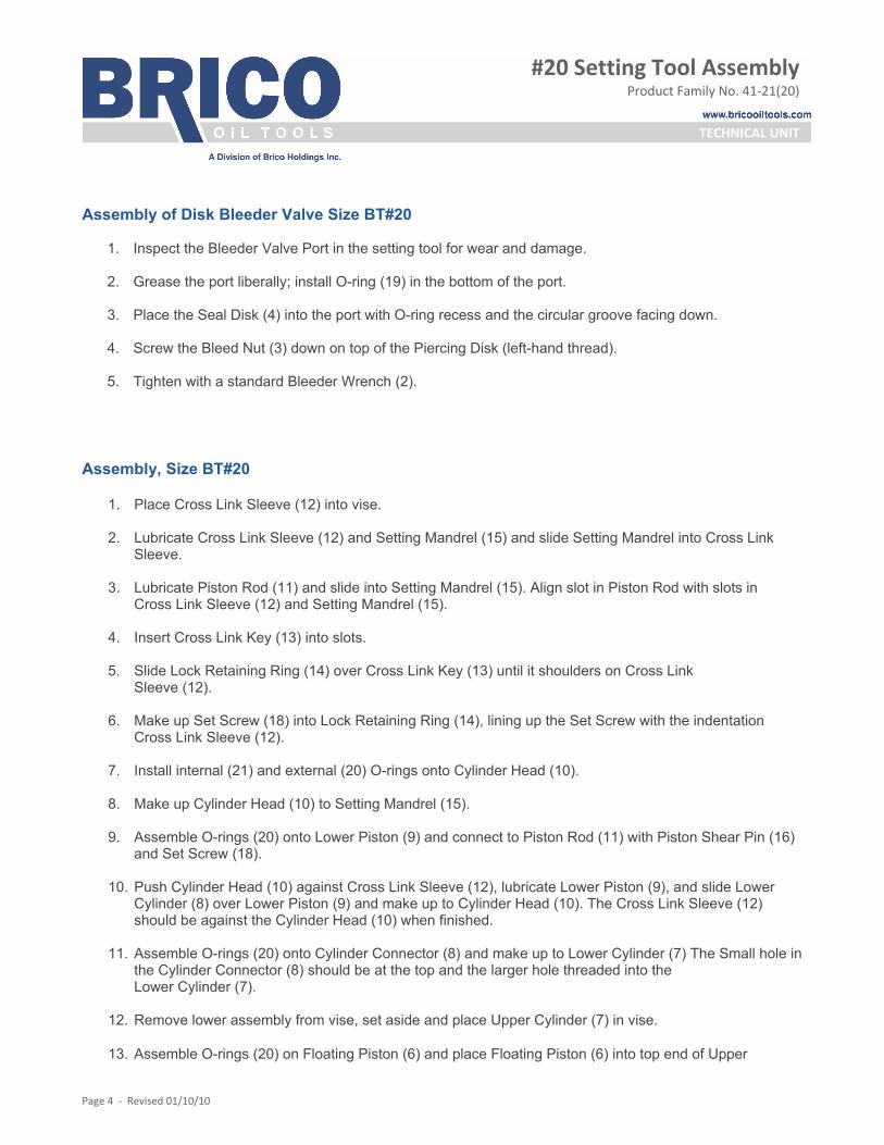
Assembly of Disk Bleeder Valve Size BT#20
1. Inspect the Bleeder Valve Port in the setting tool for wear and damage.
2. Grease the port liberally; install O-ring (19) in the bottom of the port.
3. Place the Seal Disk (4) into the port with O-ring recess and the circular groove facing down.
4. Screw the Bleed Nut (3) down on top of the Piercing Disk (left-hand thread).
5. Tighten with a standard Bleeder Wrench (2). Assembly, Size BT#20
1. Place Cross Link Sleeve (12) into vise.
2. Lubricate Cross Link Sleeve (12) and Setting Mandrel (15) and slide Setting Mandrel into Cross Link Sleeve.
3. Lubricate Piston Rod (11) and slide into Setting Mandrel (15). Align slot in Piston Rod with slots in
Cross Link Sleeve (12) and Setting Mandrel (15). 4. Insert Cross Link Key (13) into slots.
5. Slide Lock Retaining Ring (14) over Cross Link Key (13) until it shoulders on Cross Link
Sleeve (12).
6. Make up Set Screw (18) into Lock Retaining Ring (14), lining up the Set Screw with the indentation Cross Link Sleeve (12).
7. Install internal (21) and external (20) O-rings onto Cylinder Head (10).
8. Make up Cylinder Head (10) to Setting Mandrel (15).
9. Assemble O-rings (20) onto Lower Piston (9) and connect to Piston Rod (11) with Piston Shear Pin (16)
and Set Screw (18).
10. Push Cylinder Head (10) against Cross Link Sleeve (12), lubricate Lower Piston (9), and slide Lower Cylinder (8) over Lower Piston (9) and make up to Cylinder Head (10). The Cross Link Sleeve (12) should be against the Cylinder Head (10) when finished.
11. Assemble O-rings (20) onto Cylinder Connector (8) and make up to Lower Cylinder (7) The Small hole in the Cylinder Connector (8) should be at the top and the larger hole threaded into the Lower Cylinder (7).
12. Remove lower assembly from vise, set aside and place Upper Cylinder (7) in vise.
13. Assemble O-rings (20) on Floating Piston (6) and place Floating Piston (6) into top end of Upper
#20 Setting Tool Assembly Product Family No. 41‐21(20)
TECHNICAL UNIT
Page 5 ‐ Revised 01/10/10
Cylinder (7). This will have to be tapped in to the Upper Cylinder (7) with a soft dowel of wood or aluminum. The Floating Piston should only be installed to just past the threads to allow the Bleeder Pressure Chamber (5) to be threaded in.
14. Make up the Bleeder Pressure Chamber (5) to top of Upper Cylinder (7) – ensure this connection is tight. Use the soft dowel tool and push the Floating Piston to the top and bottom out on the Bleeder Pressure Chamber pin end. The Floating Piston (6) should now be making contact with the Bleeder Pressure Chamber and bottomed out at the top of the Upper Cylinder (7).
15. Set this upper half of the tool on end on the floor (bleeder end down) and fill with clean oil. Pick up the lower section and mate to the upper section. The two sections may now be made up hand tight in the vise for storage. Oil should not be installed for storage. Always clean and install new O-rings and seals after long term storage.
Note: See Oil Level Filling Information on page 3
Size BT # 20 Setting Tool - Filling Oil, Installing Charges and Tools
1. Remove the Upper Cylinder (7) from the Cylinder Connector (8). Stand the upper section of the setting tool on a clean surface with the Cylinder facing upward. Use a clean wooden dowel or broom handle to check that the Floating Piston (6) is completely bottomed out against the Bleeder Pressure Chamber (5).
2. Fill the Upper Cylinder (7) with clean oil to the proper level for the temperature at your setting depth as shown in Chart above using the Dip Stick or ruler to measure depth of Oil in the Upper Cylinder (7). Pick up the lower section of the WLPSA and make it back up into the Upper Cylinder (7) and tighten the connection.
3. Check the Bleeder Valve for proper installation and tightness. Use the Bleeder Wrench (2) to check that the Bleed Nut (3) is tight (this is a left-hand thread).
Refer to manufacture of Power Charges and Igniters for the proper selection of Power Charges
and Igniters
4. Take the Firing Head and remove the Cartridge Seat from the Head. Notice that this is a left-hand thread. Install a Secondary Igniter into the bottom end of the Cartridge Seat and use the Truarc Ring provided to retain the Secondary. Notice that no groove is provided for the Truarc Ring to snap into. The ring is held in place by friction alone and is blown out when the Igniter fires.
5. Install an Igniter into the top of the Cartridge Seat and retain with the Cartridge Seat Cap. Be sure that
the O-ring is in place between the Igniter and the Cartridge Seat and that the Cartridge Seat Cap is tightened enough to provide a good ground for the Igniter.
6. Use an Ohmmeter to check the Firing Head for electrical continuity (should read near 0 ohms resistance) from the Connector to the Firing Pin. Check for shorting (should read infinite ohms) from
the firing Pin to the Head.
7. Make up the Wireline Adapter Kit and the product to be set to the #20 Setting Tool. Refer to the Tech Unit of the specific product being set for assembly instructions.

#20 Setting Tool Assembly Product Family No. 41‐21(20)
TECHNICAL UNIT
Page 6 ‐ Revised 01/10/10
8. Remove the plastic cap from a Power Charge and place the Power Charge into the Pressure Chamber with the open end of the Power Charge facing the open end of the Pressure Chamber.
9. Remove the Firing Head from the Collar Locator or Cable Head. Install and tighten the Cartridge Seat into the Head. Then install and tighten the Firing Head into the Pressure Chamber.
10. Use a safety meter to check the resistance from the Firing Head Connector to the Head. This checks the resistance of the Igniter which should be 2.5-5 ohms for a BP-3S Igniter and confirms that the Firing Head and Igniter are installed correctly. (Other Igniters will read different and refer to Manufacturer’s Manual for correct check and equipment to be used.) Make the Firing Head back up to the Collar Locator Cable Head.
11. Pick up the tools, check zero and run in the hole at a speed no higher than 300 feet per minute, being careful to slow down when approaching the fluid level. Continue running several feet past setting depth
if possible. Check odometer and weight indicator and pick up slowly to setting depth.
12. Fire Igniter: Depending on depth, well fluid and other conditions as many as three distinct impulses can be felt manually on the electric line or observed on the weight indicator as the tools set and shear off.
13. Wait approximately one [1] minute after the last weight indicator flickers to be sure that the tool is set. Then, if possible, slack off a few feet and watch the weight indicator for a drop to indicate that the tool has set. With some tools, slacking off will re-engage the Wireline Adapter Kit and could cause you to hang up and not be able to pull free. Pick up slowly and note the setting depth by the weight increase, remembering that the #20 Setting Tool has increased about one [1] foot in length due to stroking out.
14. Retrieve the tools at a rate no higher than 300 feet per minute. A much slower rate should be used if there is any doubt about the tool being sheared off.
As soon as the Setting Tool is removed from the well, trapped pressure in the tool should be bled off through the Bleeder Valve. Bleed in an open, well-ventilated area. Place the tool so that the Bleeder Valve faces up. Locate the Bleeder Valve Vent Hole next to the Bleeder Valve. Make sure this vent hole is pointed away from all personnel. Stand on the side of the tool away from the vent hole. Bleed as follows: When using Disk Bleeder Valve, screw the Bleeder Wrench Piercing Screw in until the Piercing Disk is punctured. Do not make a full circle with the wrench. Keep hands away from the vent hole at all times. When the tool starts to
WARNING
After the Firing Head and #20 Setting have been run and fired, gas under very high pressure will be trapped inside the tool. THIS PRESSURE MUST BE BLED OFF BEFORE TRANSPORTING AND DISASSEMBLY HAS BEGUN. FAILURE TO COMPLY WITH THE FOLLOWING BLEEDING INSTRUCTIONS MAY RESULT IN SERIOUS INJURY. DO NOT TRANSPORT THE TOOL UNTIL THE PRESSURE HAS BEEN BLED OFF. PPE / Safety glasses, gloves and long sleeves must be worn while bleeding pressure off of the Setting Tool. The Setting Tool should always be bled in a well-ventilated area.

#20 Setting Tool Assembly Product Family No. 41‐21(20)
TECHNICAL UNIT
Page 7 ‐ Revised 01/10/10
bleed, make an additional half a turn and then stop. Do not screw the Piercing Screw in tight. It can seal against the Piercing Disk and pre-vent bleeding. Do not turn the Piercing Screw to the right until the tool is completely bled off. If the tool does not bleed off when the Piercing Screw is bottomed out, carefully turn it back 1/4 turn, watching to be sure that the Bleed Nut does not turn. If the tool still will not bleed off, do not remove the Piercing Screw, use the “Secondary Bleeding Procedure” described below.
15. Redress the Setting Tool before running again. Secondary Bleeding Procedure The Disk Bleeder Valve can be run in the Heavy Duty Setting Tool, but the Manual Bleeder Valve cannot. If you do not have a Disk Bleeder Valve for the heavy duty tool, a Pressure Chamber less Bleeder Valve must be run. The following bleeding procedure must then be used. This procedure can also be used on any tool if either Bleeder Valve fails to bleed pressure off the tool. Safety glasses, gloves and long sleeves must be worn while bleeding pressure off of the Setting Tool. The Setting Tool should be bled in a well-ventilated area. Before attempting the secondary bleed-off procedure, allow 6 to 8 hours for the tool to cool down, this cool down period will reduce the high pressure within the tool. Clean any debris from the bleed hole in the top end of the Upper Cylinder (7). Hold back up on pressure chamber. Position bleeder hole in pressure chamber away from you and slowly unscrew firing head a maximum of 1-1/4" from pressure chamber. If pressure does not bleed off position bleeder holes in upper cylinder away from you and slowly unscrew pressure chamber until pressure escapes. Do not back off pressure chamber more than 1-1/4” from cylinder at this point. If pressure still does not bleed off, back off firing head exactly 1-1/4” from pressure chamber. If the tool cannot be bled off, contact the BRICO OIL TOOLS representative. In Case of Accident Power Charge products of combustion are:
Potassium Chloride Strontium Oxide Oxides of Nitrogen both nitrous and nitric Carbon Dioxide Carbon Nitrogen-based hydrocarbons Unburned asphalt Acetic fraction and paraffin
The above information is provided for use in administering medical attention only.
#20 Setting Tool Assembly Product Family No. 41‐21(20)
TECHNICAL UNIT
Page 8 ‐ Revised 01/10/10
Running in Extreme Temperatures When running in temperatures expected to be in excess of 350 degrees F, it is suggested that the Gage Ring, Wireline Feeler and Junk Catcher be run on the Firing Head with an Igniter in place. After the run, check the Firing Head for leaks and high temperature firing of the Igniter. If the Igniter has been fired by high well temperatures, it will be impossible to run the Setting Tool to the setting depth without danger of premature setting. If any fluid is found inside the Firing Head, all parts must be dried, sealing surfaces examined and all O-rings inspected and replaced. It is very important that all new O-rings be used when the Setting Tool is run, as fluid around the Pin would prevent the Firing Head from operating. Do not reuse the Igniter! Discard and use a new Igniter. It is a good idea to find the setting depth on the Gage Ring run and flag the Wireline at setting depth. Then run in the hole as fast as possible for the tools being run and fire the setting tool as soon as the flag is reached and the Wireline has quit oscillating. This will minimize the temperature that the Power Charge and Igniters will heat up to before being fired. Disassembly BT#20
1. Lay tools down, being careful not to damage Adapter kit. Place in a well-ventilated area and bleed as follows: a) Disk Bleeder Valve: Place the tool so that the Bleeder Valve faces up. Locate the Bleeder Valve Vent Hole
next to the Bleeder Valve. Make sure this vent hole is pointed away from all personnel. Stand on the side of the tool away from the vent hole. Screw the threaded portion of the Bleeder Wrench (2) into the Bleed Nut until the Piercing Disk is punctured. Do not make a full circle with the wrench, keep hands away from the vent hole at all times. When the tool starts to bleed, make an additional half turn and then stop. Do not screw the threaded portion of the Bleeder Wrench in tight. It can seal against the Piercing Disk and prevent bleeding. Do not turn the Bleeder Wrench to the right until the tool is completely bled off. If the tool does not bleed off when the threaded portion of the Bleeder Wrench is bottomed out, carefully turn it back 1/4 turn, watching to be sure that the Disk Retainer does not turn. If the tool still will not bleed off, do not remove the Piercing Screw, use the “Secondary Bleeding Procedure”.
2. Unscrew Cable Head. Important: If the Cable Head is tight, indicating that pressure has leaked into it,
follow “Secondary Bleeding Procedure” under Operating Instructions. All Pressurized gas must be exhausted before disassembly is begun.
3. Clean out bleed holes in the Cylinders (7).
WARNING
After the Firing Head and #20 Setting Tool have been run and fired, gas under very high pressure will be trapped inside the tools. THIS PRESSURE MUST BE BLED OFF BEFORE TRANSPORTING and DISASSEMBLY HAS BEGUN. FAILURE TO COMPLY WITH THE FOLLOWING BLEEDING INSTRUCTIONS MAY RESULT IN SERIOUS INJURY. PPE / Safety glasses, gloves and long sleeves must be worn while bleeding pressure off of the Setting Tool. The Setting Tool should always be bled in a well-ventilated area.

#20 Setting Tool Assembly Product Family No. 41‐21(20)
TECHNICAL UNIT
Page 9 ‐ Revised 01/10/10
4. Place in vise on Cylinder (7), position the bleed hole away from you and slowly unscrew the Pressure Chamber (5) a distance of no more than 1-1/4" from the Cylinder to allow any pressure that may still be in Cylinder to escape.
5. Reposition in vise on Cylinder (7) position the bleed hole away from you and slowly unscrew Cylinder Head (8) until any trapped pressure escapes through the bleed hole. Do not back off Cylinder Head from Cylinder more than 1-1/ 4" at this point.
6. Once all pressure has been bled off, unscrew and remove Firing Head.
7. Remove the Adapter Kit from the Setting Tool.
8. Remove the Bleeder Valve. Use Bleeder Wrench (2) to remove Bleed Nut 3 (left-hand thread). Use a small screwdriver or similar tool to remove Seal Disk (4).
9. Remove Power Chamber (5) 10. Remove Cylinder (7). 11. Using an aluminum tube, dowel rod, or broomstick, push burnt Power Charge from the Cylinder (7). 12. Push Piston (6) out of lower end of Cylinder (7).
13. Remove Set Screw and slide Link Retaining Ring (14) up off of Cross Link Sleeve (12).
14. Remove Cross Link (13).
15. Remove Cross Link Sleeve (12) and Lock Retaining Ring (14).
16. Remove Set Screw and remove Setting Mandrel (15).
17. Unscrew Cylinder Head (10) and remove along with Piston (9) and Piston Rod (11). Catch and discard
oil from tool.
18. Remove Retaining Pin and separate Piston (9) from Piston Rod (11).
19. Pull Piston Rod (11) from lower end of Cylinder Head (10).
20. Remove Cylinder Connector (8).
21. Remove and discard all O-rings.
22. Clean and inspect all parts for wear or damage. NOTE: For field clean up following the use of the Setting Tool go through Step 12. Wash parts with water, kerosene, or by swabbing with oil rags, reassemble these parts hand tight without O-rings as soon as possible. The tool should be completely disassembled and thoroughly cleaned before being reassembled and run again.
#20 Setting Tool Assembly Product Family No. 41‐21(20)
TECHNICAL UNIT
Page 10 ‐ Revised 01/10/10
#20 Setting Tool - 10.5" / 266.7mm Setting Stroke Item QTY Description Part Number 1 #20 Setting Tool 41-2109720-00 1 1 Adjuster Sub 41-2109720-01 2 1 Bleed Wrench 41-2109720-02 3 1 Bleed Nut 41-2109720-03 4 1 Seal Disc 41-2109720-04 5 1 Pressure Chamber w/Bleeder Valve 41-2109720-05 6 1 Floating Piston 41-2109720-06 7 2 Hydraulic Cylinder 41-2109720-07 8 1 Cylinder Connector 41-2109720-08 9 1 Bottom Piston 41-2109720-09 10 1 Cylinder Head 41-2109720-10 11 1 Piston Rod 41-2109720-11 12 1 Crosslink Sleeve 41-2109720-12 13 1 Crosslink Key 41-2109720-13 14 1 Lock Retaining Ring 41-2109720-14 15 1 Setting Mandrel 41-2109720-15 16 1 Shear Pin Set Screw 41-2109720-21 17 1 Set Screw 3/8" - 16 x 5/8" 82-3863160-00 18 2 Set Screw 3/8" - 16 x 3/8" 82-3838160-00 Redress Kit 19 1 O-Ring 81-0213000-02 20 14 O-Ring 81-0334000-02 21 2 O-Ring 81-0216000-02 Ballistics #20 Standard Power Charge 66-1220100-00 #20 Slow Set Power Charge 66-1220200-00 Secondary Igniters 66-2200020-00 Primary Igniter (PB3 Style) 66-2200010-00

#20 Setting Tool Assembly Product Family No. 41‐21(20)
TECHNICAL UNIT
Page 11 ‐ Revised 01/10/10