Embed Size (px)
Citation preview

OceanStor 2200 V3 Storage SystemV300R006
Product Description
Issue 01
Date 2017-02-28
HUAWEI TECHNOLOGIES CO., LTD.

Copyright © Huawei Technologies Co., Ltd. 2017. All rights reserved.No part of this document may be reproduced or transmitted in any form or by any means without prior writtenconsent of Huawei Technologies Co., Ltd. Trademarks and Permissions
and other Huawei trademarks are trademarks of Huawei Technologies Co., Ltd.All other trademarks and trade names mentioned in this document are the property of their respectiveholders. NoticeThe purchased products, services and features are stipulated by the contract made between Huawei and thecustomer. All or part of the products, services and features described in this document may not be within thepurchase scope or the usage scope. Unless otherwise specified in the contract, all statements, information,and recommendations in this document are provided "AS IS" without warranties, guarantees orrepresentations of any kind, either express or implied.
The information in this document is subject to change without notice. Every effort has been made in thepreparation of this document to ensure accuracy of the contents, but all statements, information, andrecommendations in this document do not constitute a warranty of any kind, express or implied.
Huawei Technologies Co., Ltd.Address: Huawei Industrial Base
Bantian, LonggangShenzhen 518129People's Republic of China
Website: http://www.huawei.com
Email: [email protected]
Issue 01 (2017-02-28) Huawei Proprietary and ConfidentialCopyright © Huawei Technologies Co., Ltd.
i

About This Document
PurposeThis document describes the orientation, features, architecture, technical specifications,product configuration, environment requirements, standard compliance and grantedcertifications of the OceanStor 2200 V3 storage system.
Intended AudienceThis document is intended for: All readers
Symbol ConventionsThe symbols that may be found in this document are defined as follows.
Symbol Description
DANGERIndicates an imminently hazardous situation which, if notavoided, will result in death or serious injury.
WARNINGIndicates a potentially hazardous situation which, if notavoided, could result in death or serious injury.
Indicates a potentially hazardous situation which, if notavoided, may result in minor or moderate injury.
Indicates a potentially hazardous situation which, if notavoided, could result in equipment damage, data loss,performance deterioration, or unanticipated results.NOTICE is used to address practices not related topersonal injury.
OceanStor 2200 V3 Storage SystemProduct Description About This Document
Issue 01 (2017-02-28) Huawei Proprietary and ConfidentialCopyright © Huawei Technologies Co., Ltd.
ii

Symbol Description
NOTE Calls attention to important information, best practices andtips.NOTE is used to address information not related topersonal injury, equipment damage, and environmentdeterioration.
Change HistoryChanges between document issues are cumulative. The latest document issue contains all thechanges made in earlier issues.
Issue 01 (2017-02-28)This issue is the first official release.
OceanStor 2200 V3 Storage SystemProduct Description About This Document
Issue 01 (2017-02-28) Huawei Proprietary and ConfidentialCopyright © Huawei Technologies Co., Ltd.
iii

Contents
About This Document.....................................................................................................................ii
1 Product Positioning.......................................................................................................................1
2 Product Features.............................................................................................................................3
3 Typical Applications.....................................................................................................................93.1 High-Performance Applications................................................................................................................................... 103.2 High-Availability Applications.....................................................................................................................................113.3 High-Density and Multi-Service Applications............................................................................................................. 13
4 Hardware Architecture............................................................................................................... 164.1 Device Composition..................................................................................................................................................... 174.2 2 U Controller Enclosure .............................................................................................................................................174.2.1 Overview................................................................................................................................................................... 174.2.2 Component Description.............................................................................................................................................214.2.2.1 System Enclosure................................................................................................................................................... 214.2.2.2 Controller................................................................................................................................................................224.2.2.3 Power Module.........................................................................................................................................................254.2.2.4 Disk Module........................................................................................................................................................... 274.2.2.5 10GE Electrical Interface Module..........................................................................................................................284.2.2.6 GE Electrical Interface Module..............................................................................................................................304.2.2.7 SmartIO Interface Module......................................................................................................................................314.2.3 Indicator Introduction................................................................................................................................................ 334.3 2 U Disk Enclosure (2.5-Inch Disks)............................................................................................................................394.3.1 Overview................................................................................................................................................................... 394.3.2 Component Description.............................................................................................................................................404.3.2.1 System Enclosure................................................................................................................................................... 404.3.2.2 Expansion Module..................................................................................................................................................414.3.2.3 Power Module.........................................................................................................................................................434.3.2.4 Disk Module........................................................................................................................................................... 444.3.3 Indicator Introduction................................................................................................................................................ 454.4 4 U Disk Enclosure (3.5-Inch Disks)............................................................................................................................484.4.1 Overview................................................................................................................................................................... 484.4.2 Component Description.............................................................................................................................................504.4.2.1 System Enclosure................................................................................................................................................... 50
OceanStor 2200 V3 Storage SystemProduct Description Contents
Issue 01 (2017-02-28) Huawei Proprietary and ConfidentialCopyright © Huawei Technologies Co., Ltd.
iv

4.4.2.2 Expansion Module..................................................................................................................................................514.4.2.3 Power Module.........................................................................................................................................................524.4.2.4 Fan Module.............................................................................................................................................................534.4.2.5 Disk Module........................................................................................................................................................... 544.4.3 Indicator Introduction................................................................................................................................................ 564.5 Device Cables............................................................................................................................................................... 584.5.1 Power Cables............................................................................................................................................................. 594.5.2 Ground Cables........................................................................................................................................................... 604.5.3 Network Cables......................................................................................................................................................... 604.5.4 Serial Cables.............................................................................................................................................................. 614.5.5 Mini SAS HD Cables................................................................................................................................................ 614.5.5.1 Mini SAS HD Electrical Cables............................................................................................................................. 614.5.5.2 Mini SAS HD optical cables.................................................................................................................................. 624.5.6 Optical Fibers............................................................................................................................................................ 63
5 Software Architecture................................................................................................................. 64
6 Product Specifications................................................................................................................ 716.1 Hardware Specifications...............................................................................................................................................726.2 Software Specifications................................................................................................................................................ 77
7 Environmental Requirements................................................................................................... 837.1 Temperature, Humidity, and Altitude........................................................................................................................... 847.2 Vibration and Shock..................................................................................................................................................... 857.3 Particle Contaminants...................................................................................................................................................857.4 Corrosive Airborne Contaminants................................................................................................................................867.5 Heat Dissipation and Noise.......................................................................................................................................... 89
8 Standards Compliance................................................................................................................91
9 Certifications................................................................................................................................ 96
10 Operation and Maintenance....................................................................................................99
A How to Obtain Help.................................................................................................................101A.1 Preparations for Contacting Huawei..........................................................................................................................102A.1.1 Collecting Troubleshooting Information................................................................................................................ 102A.1.2 Making Debugging Preparations............................................................................................................................ 102A.2 How to Use the Document.........................................................................................................................................102A.3 How to Obtain Help from Website............................................................................................................................ 102A.4 Ways to Contact Huawei............................................................................................................................................103
B Glossary...................................................................................................................................... 104
C Acronyms and Abbreviations................................................................................................ 105
OceanStor 2200 V3 Storage SystemProduct Description Contents
Issue 01 (2017-02-28) Huawei Proprietary and ConfidentialCopyright © Huawei Technologies Co., Ltd.
v

1 Product Positioning
The OceanStor 2200 V3 storage system is storage product newly developed by HuaweiTechnologies Co., Ltd (Huawei for short). This series is ideal for processing existing storageapplications and follows the development trend of storage technologies. It meets medium- andlarge-sized enterprises' storage requirements for massive data storage, fast data access, highavailability, high utilization, energy saving, and ease-of-use.
Business development leads to a great amount of service data, which poses high demands onstorage systems. Traditional storage systems fail to meet these demands and encounter thefollowing bottlenecks: inflexible storage performance expansion, complex management ofvarious devices, failure to utilize legacy devices, and increasing maintenance costs occupyinga large part of Total Cost of Ownership (TCO). To eliminate these bottlenecks, Huawei haslaunched the OceanStor 2200 V3 storage system.
The OceanStor 2200 V3 storage system offers comprehensive and superb solutions byproviding industry-leading performance, diverse efficiency boost mechanisms, as well as file-level and block-level data storage and various storage protocols on a single platform. Thosesolutions help customers maximize their return on investment (ROI) and meet therequirements of different application scenarios such as Online Transaction Processing (OLTP)and Online Analytical Processing (OLAP) of large databases, high-performance computing(HPC), digital media, Internet operation, centralized storage, backup, disaster recovery, anddata migration.
In addition to providing high-performance storage services for application servers, theOceanStor 2200 V3 storage system supports advanced data backup and disaster recoverytechnologies, ensuring the secure and smooth running of data services. Also, the OceanStor2200 V3 storage system offers easy-to-use management modes and convenient local/remotemaintenance modes, greatly decreasing the management and maintenance costs.
Position and Application of the Storage System on a SAN NetworkFigure 1-1 shows the position and application of the OceanStor 2200 V3 storage system on aSAN network.
OceanStor 2200 V3 Storage SystemProduct Description 1 Product Positioning
Issue 01 (2017-02-28) Huawei Proprietary and ConfidentialCopyright © Huawei Technologies Co., Ltd.
1
Figure 1-1 Position and application of the storage system on a SAN network
FC SAN/IP SAN application Block R/W
Connecting through the Ethernet/Management and maintenance through the visualized management tool
Backup medium
Local backup/Remote backup
Administrator
Service Engineer
Backup Server
Storage SystemRemote maintenance/Local maintenance
Remote storage devices
SAN Application Hosts
Backup management
Remote disaster recovery application/SAN remote mirroring
OceanStor 2200 V3 Storage SystemProduct Description 1 Product Positioning
Issue 01 (2017-02-28) Huawei Proprietary and ConfidentialCopyright © Huawei Technologies Co., Ltd.
2

2 Product Features
Powered by a superior hardware structure, an integrated block and file software architecture,as well as advanced data applications and protection technologies, the OceanStor 2200 V3storage system provides high performance, superb scalability, robust reliability, and highavailability, meeting medium- and large-sized enterprises' different storage requirements.
High Performance
The OceanStor 2200 V3 storage system offers a three-level performance accelerationtechnology, and delivers hierarchical performance for different applications. The three levelsare:
1. Superior hardware
The OceanStor 2200 V3 storage system is equipped with multi-core processors, high-speed and large-capacity caches, and various high-speed interface modules. The superiorhardware allows the OceanStor 2200 V3 storage system to offer better storageperformance than tradition storage systems.
2. SmartTier
The SmartTier technology identifies hotspot data and periodically promotes them tohigh-performance storage medium for a performance boost. In addition, SmartTiersupports solid state drive (SSD) data caching, accelerating access to hotspot data.
3. SSDs
The OceanStor 2200 V3 storage system can be fully configured with SSDs to providepeak performance for the most-demanding applications.
Flexible Scalability
The OceanStor 2200 V3 storage system has an outstanding scalability. It supports varioustypes of disks and host interface modules. Also, the interface modules have a high density.The supported multiple types and high-density interface modules bring a high systemscalability.
The OceanStor 2200 V3 storage system supports the following types of disks and interfacemodules:
l Types of disks:
SAS disks, NL-SAS disks, and SSDs.
OceanStor 2200 V3 Storage SystemProduct Description 2 Product Features
Issue 01 (2017-02-28) Huawei Proprietary and ConfidentialCopyright © Huawei Technologies Co., Ltd.
3

l Types of host interface modules:GE, 10GE and SmartIO.
NOTE
SmartIO interface modules support various ports including 16 Gbit/s Fibre Channel ports, 8 Gbit/sFibre Channel ports, 10 Gbit/s FCoE (VN2VF) ports, 10 Gbit/s Ethernet ports, and iWARP(interconnection between Scale-out nodes).
Proven ReliabilityThe OceanStor 2200 V3 storage system offers protection measures against component failuresand power failure, and uses advanced technologies to minimize risks of disk failures and dataloss. This ensures the proven reliability of the storage system.
l Against component failuresThe storage system components are in 1+1 redundancy and work in active-active mode.Normally, every two components work simultaneously and share loads. If onecomponent fails or gets offline, the other one takes over all loads and speeds up tocompensate. The whole process is transparent to applications.
l RAID 2.0+ underlying virtualizationThe storage system employs innovative RAID 2.0+ underlying virtualization technologyfor automatic load balancing. If a disk encounters a fault, all the other disks in the samedisk domain help construct the faulty disk's service data, achieving a 20-fold fasterreconstruction speed than traditional RAID technology. In addition, RAID 2.0+significantly reduces the possibility of multi-disk failure.
l Against unexpected downtimeThe storage system is equipped with backup power modules that provide power for thecontroller enclosure in the event of a power failure. This protects the data in the cacheand dumps it to the build-in disks of the controllers to avoid data loss.
l Bad sector repairThe storage system is prone to bad sectors of disks. The OceanStor 2200 V3 storagesystem adopts the bad sector repair technology to proactively detect and repair badsectors, reduce the disk failure rate by 50%, and prolong the service life of disks.
l Disk pre-copyThe disk pre-copy technology enables the storage system to routinely check the hardwarestatus and migrate data from any failing disk to minimize the risks of data loss.
High AvailabilityThe OceanStor 2200 V3 storage system uses TurboModule, online capacity expansion, anddisk roaming technologies to provide high availability for applications and nonstop systemrunning during maintenance. The functions of TurboModule, online capacity expansion, anddisk roaming are as follows:l TurboModule enables controllers, fans, power modules, interface modules, BBUs, and
disks to be hot-swapped without restarting the storage system, allowing onlineoperations.
l Dynamic capacity expansion enables users to add disks to a disk domain in an online andeasy manner.
l Disk roaming enables a storage system to automatically identify relocated disks andresume their services.
OceanStor 2200 V3 Storage SystemProduct Description 2 Product Features
Issue 01 (2017-02-28) Huawei Proprietary and ConfidentialCopyright © Huawei Technologies Co., Ltd.
4
The OceanStor 2200 V3 storage system provides multiple advanced data protectiontechnologies to protect data integrity and continuous system running even when catastrophicdisasters happen. Advanced data protection technologies of the OceanStor storage system aresnapshot, LUN copy, remote replication, clone and HyperMirror:l Snapshot generates multiple point-in-time images for the source LUN (Logical Unit
Number) or source file system data. The snapshot images can be used to recover dataquickly when needed.
l LUN copy backs up data among heterogeneous storage systems for data protection.l Remote replication backs up local data onto a remote storage system for disaster
recovery.l Clone preserves a real-time physical copy of a source LUN for the high availability of
local data.l HyperMirror backs up data in real time. If the source data becomes unavailable,
applications can automatically use the data copy, ensuring high data security andapplication continuity.
The OceanStor 2200 V3 storage system employs multiple resource application technologiesand provides flexible resource management to protect customers' storage investments. Theresource application technologies include SmartVirtualization, and SmartMigration.l SmartVirtualization enables a local storage system to centrally manage storage resources
of third-party storage systems, simplifying storage system management and reducingmaintenance costs.
l SmartMigration migrates LUNs in or between storage systems, adjusting and allocatingresources along with business development.
The OceanStor 2200 V3 storage system supports memory upgrade so that storageperformance matches service development.
High System Security
Storage Network Securityl Security of management channels
The management operations from physical ports are controlled by the accessauthentication mechanism of the storage system, and only authorized users are allowedto manage the storage system.
l Anti-attack protection for protocols and portsThe storage system provides only necessary ports to the external for system operationsand maintenance. All the ports used are listed in the Communication Matrix. Dynamiclistening ports are functioning in the proper scope, and no unopened port exists.
l Service ports are isolated from management portsThe Access Control List (ACL) mechanism is adopted to isolate Ethernet ports frominternal heartbeat network ports, management network ports, and maintenance networkports.
NOTE
Internal heartbeat links are established between controllers for these controllers to detect eachother's working status. You do not need to separately connect cables.
Storage Service Securityl Security of the operating system
OceanStor 2200 V3 Storage SystemProduct Description 2 Product Features
Issue 01 (2017-02-28) Huawei Proprietary and ConfidentialCopyright © Huawei Technologies Co., Ltd.
5

The storage system uses a dedicated operating system. Security of the operating systemhas been hardened before the storage system is delivered. The storage systems updatesecurity patches for their operating systems and open-source software based on siterequirements, safeguarding users' data.
l Data storage encryptionThe storage system supports data encryption by using a network password manager. Thenetwork password manager employs the standard cryptographic algorithm supported bythe State Encryption Administration of China. It allows only the hosts that comply withsecurity policies to access storage system data by auditing access control policies andcontrolling access attempts from hosts. After the network password manager is deployed,all mutual information between the hosts and storage system will pass the networkpassword manager to enable read/write data encryption and decryption and ensure datasecurity of the storage system.
l Data destructionWhen deleting unwanted data, the system erases the specified LUN to make the deleteddata unable to be restored, preventing critical data leaks.
Storage Management Security
The operations of users can be allowed and denied. All management operations are logged bythe system.
Virtualization, Intelligence, and EfficiencyThe OceanStor 2200 V3 storage system absorbs the concept of "Virtualization, Intelligence,and Efficiency", which fits the up-to-date storage design idea and wins a leading position forthe storage system. Compared with traditional storage systems, the OceanStor 2200 V3storage system achieves a higher storage space usage, faster data reconstruction speed,smarter performance allocation technology, and finer service quality control. To obtain theprevious achievements, the following technologies contribute:l RAID 2.0+ underlying virtualization
RAID 2.0+ underlying virtualization technology divides disk storage space into small-sized data blocks and uses the blocks to create RAID groups for fine-grained resourcemanagement. The technology realizes automatic load balancing, higher storageperformance, better storage space utilization, faster disk reconstruction, and delicatestorage space management. RAID 2.0+ serves as a basis for a number of other advancedstorage technologies.
l SmartTier (intelligent storage tiering)Enables a storage system to automatically analyze data access frequency per unit timeand relocate data to disks of different performance levels based on the analysis result.(High-performance disks store hot data, performance disks store warm data, and large-capacity disks store cold data.) In this way, the optimal overall performance is achievedand the IOPS cost is reduced.
l SmartQoS (intelligent service quality control)Enables a storage system to categorize service data based on data characteristics (eachcategory represents a type of application) and set a priority and performance objectivefor each category. In this way, resources are provided for services properly, ensuringmission-critical services' performance.
l Thin provisioningAllows on-demand allocation of storage space rather than the traditional method of pre-allocating all storage space at the initial stage. It is more efficient because the amount of
OceanStor 2200 V3 Storage SystemProduct Description 2 Product Features
Issue 01 (2017-02-28) Huawei Proprietary and ConfidentialCopyright © Huawei Technologies Co., Ltd.
6

resources used is close to the amount of resources allocated. In this way, the initialpurchase cost and total cost of ownership are reduced.
l SmartCache (intelligent storage cache)Uses SSDs as cache resources to significantly promote system read performance whenrandom, small I/Os with hot data require more read operations than write operations.
Economy and Ease-of-Use
The OceanStor 2200 V3 storage system employs intelligent CPU frequency control, delicatefan speed control, deduplication and compression to improve economy. It also provides aseries of management and maintenance tools to simplify operation and maintenance tasks.
l Economy– Intelligent CPU frequency control
Automatically changes the CPU frequency based on the system loads. It decreasesthe CPU frequency and power consumption during off-peak hours for a lowoperation cost and long CPU service life.
– Delicate fan speed controlDynamically adjusts the fan speed based on the storage system's temperature. Itlowers the noise and power consumption and cuts the operation cost.
– Deduplication and compressionChecks and processes duplicate data in disks based on deduplication, and minimizesspace occupied by data based on compression to improve disk utilization.
– OceanStor 2200 V3 storage system can be configured with one controller, meetingcustomers' requirements for low-cost storage systems.
l Ease-of-use– DeviceManager
DeviceManager is a storage system management tool based on a graphical userinterface (GUI) and enables you to efficiently manage storage systems by wizard-based operations in batch.
– Storage resource configuration tool: SmartConfigInstalled on application servers, SmartConfig is a piece of software providing easymanagement of storage systems. With this tool, only three steps are needed toeasily, flexibly, and effectively divide storage resources into disks and mount themto servers.
– Integrated managementImplements convenient device management by integrating a management plug-ininto mainstream management software such as VMware vCenter plug-in, Hyper-VSystem Center, vSphere API for Storage Awareness (VASA), vSphere Storage APIsfor Array Integration (VAAI), and Volume Shadow Copy Service (VSS) Provider.
– Pad managementSupports flexible storage system management on a pad.
– Various alarm notification methodsProvides alarm notification by sound, indicator, short message service (SMS), oremail.
– One-click upgrade tool
OceanStor 2200 V3 Storage SystemProduct Description 2 Product Features
Issue 01 (2017-02-28) Huawei Proprietary and ConfidentialCopyright © Huawei Technologies Co., Ltd.
7

Provides one-click upgrade for controllers. It simplifies the upgrade operation andmakes the procedure transparent to users.
OceanStor 2200 V3 Storage SystemProduct Description 2 Product Features
Issue 01 (2017-02-28) Huawei Proprietary and ConfidentialCopyright © Huawei Technologies Co., Ltd.
8

3 Typical Applications
About This Chapter
The OceanStor 2200 V3 storage system offers industry-leading hardware specifications, aflexible and reliable hardware design, a virtualized underlying architecture, and a variety ofdata protection technologies, addressing the needs of differentiated storage applications. Thetypical applications of the OceanStor 2200 V3 storage system include but are not limited tohigh-performance, high-availability, or multi-service applications.
3.1 High-Performance ApplicationsThe OceanStor 2200 V3 storage system incorporates various technologies to boost the systemperformance. Its high-performance hardware delivers outstanding data access performance.The virtualization technology can improve the storage performance continuously and itshatters performance bottlenecks caused by data explosion. The intelligent data tieringtechnology SmartTier automatically detects and prioritizes hotspot data. Therefore, theOceanStor 2200 V3 storage system is a great choice for the high-performance applications.
3.2 High-Availability ApplicationsThe OceanStor 2200 V3 storage system has a highly reliable design, achieving a long meantime between failures (MTBF), and ensuring high availability of storage applications. It alsoincorporates a variety of data protection technologies, and protects data integrity and servicecontinuity against catastrophic disasters.
3.3 High-Density and Multi-Service ApplicationsThe OceanStor 2200 V3 storage system delivers industry-leading density of interface modulesin an enclosure and a flexible configuration of interface modules and hard disks of differenttypes. This design makes the OceanStor 2200 V3 storage system suitable for high-density andmulti-service applications.
OceanStor 2200 V3 Storage SystemProduct Description 3 Typical Applications
Issue 01 (2017-02-28) Huawei Proprietary and ConfidentialCopyright © Huawei Technologies Co., Ltd.
9

3.1 High-Performance ApplicationsThe OceanStor 2200 V3 storage system incorporates various technologies to boost the systemperformance. Its high-performance hardware delivers outstanding data access performance.The virtualization technology can improve the storage performance continuously and itshatters performance bottlenecks caused by data explosion. The intelligent data tieringtechnology SmartTier automatically detects and prioritizes hotspot data. Therefore, theOceanStor 2200 V3 storage system is a great choice for the high-performance applications.
On-Demand System Performance BoostThe performance of a storage system was provisioned to meet the initial applicationrequirements. However, the future growth of applications is always beyond expectation, andthe performance of a traditional storage system is gradually consumed up and finally restrictsthe system functionality. The virtualization technology of the OceanStor 2200 V3 storagesystem can address this issue. It dynamically increases storage performance based on theapplication requirement. This prolongs the system service life and lowers customers' total costof ownership (TCO).
After the initial purchase, the storage system is equipped with affordable hard disk drives(HDDs) to deliver data storage services. As the service requirements increase and the storagesystem performance becomes insufficient, administrators can add HDDs of high speeds orSSDs to boost the system performance. When the service requirements reach a new peak andare starved of storage system performance, administrators can replace all the existing HDDswith SSDs to further adapt the system performance to the new requirements.
This on-demand system performance boost brings the following benefits:l The system performance is improved gradually, balancing the return on investment
(ROI) and the system service life.l Components for upgrade are available, following the Moore's Law to reduce the
purchase cost and the TCO.
Dynamic Storage Tiering for Hotspot DataIn media and website applications, the hot news are of high access frequency and generatehotspot data. Those hotspot data receive simultaneous read and write requests from a largenumber of servers, and pose a demanding requirement on storage system performance.Traditional storage systems fail to address such a storage requirement.
The OceanStor 2200 V3 storage system uses its resident intelligent data tiering technology,SmartTier, to identify hotspot data and promote them to high-performance SAS disks orSSDs. If SmartTier later finds out that the hotspot data becomes cold (receiving less accessrequests), it demotes the data to low-performance disks and clear storage space for newhotspot data. Figure 3-1 depicts the working principle of the SmartTier.
OceanStor 2200 V3 Storage SystemProduct Description 3 Typical Applications
Issue 01 (2017-02-28) Huawei Proprietary and ConfidentialCopyright © Huawei Technologies Co., Ltd.
10

Figure 3-1 SmartTier working principle
Data server Mail server Video server File server
SmartTier
Network Network
Hotspot Data flow
Storage pool
High-performance Tier disks (SSD)
Performance Tier disks (SAS)
Capacity Tier disks (NL-SAS)
SmartTier
SmartTier
3.2 High-Availability ApplicationsThe OceanStor 2200 V3 storage system has a highly reliable design, achieving a long meantime between failures (MTBF), and ensuring high availability of storage applications. It alsoincorporates a variety of data protection technologies, and protects data integrity and servicecontinuity against catastrophic disasters.
In-Service Routine Maintenance
In traditional storage systems, routine maintenance tasks, such as component replacement andcapacity expansion, must be implemented in offline mode. The OceanStor 2200 V3 storagesystem, however, assembles advanced technologies for in-service routine maintenance:
l TurboModule
Enables online replacement of components and requires no system restart.
l Online capacity expansion
Allows online addition of disks and expansion of storage pools.
OceanStor 2200 V3 Storage SystemProduct Description 3 Typical Applications
Issue 01 (2017-02-28) Huawei Proprietary and ConfidentialCopyright © Huawei Technologies Co., Ltd.
11

Tolerance of Single Points of FailuresThe OceanStor 2200 V3 storage system incorporates a hierarchical redundancy design toeliminate the impact of single points of failure:l Hardware redundancy
All components of the OceanStor 2200 V3 storage system are in redundancy and work inactive-active mode. If one component fails, the other speeds up to compensate so that thestorage system can continue operating.
l Link redundancyIf there is only one link between the storage system and an application server, thedisconnection of the link terminates their communication in between. To eliminate thisfailure, the OceanStor 2200 V3 storage system uses two or more links to communicatewith the application server. Therefore, if one link is down, the other links take over theservices to continue the data transmission.
l Application server clusteringIf the storage system cooperates with only one application server, the failure of theapplication server interrupts services. Application server clustering can address thisissue. A cluster consists of two or more application servers that share loads. If oneapplication server in the cluster fails, the other application servers take over its loads, andthe whole process is transparent to users. Application server clustering supported by theOceanStor 2200 V3 storage system ensures business continuity.
Based on the previous protection mechanisms, the OceanStor 2200 V3 storage system hasproven tolerance of single points of failure, as shown in Figure 3-2.
Figure 3-2 Tolerance of single points of failure
Application server A
Cluster
Storage array
Controller A Controller B
Heartbeat cable
Normal
Failure point
Abnormal
Data flow in normal cases
Data flow in abnormal cases
Application server B
Application server A
Controller A Controller B
Heartbeat cable
Data channel
Network
Application server B
Network
Data channel
Cluster
Storage array
Physical link
OceanStor 2200 V3 Storage SystemProduct Description 3 Typical Applications
Issue 01 (2017-02-28) Huawei Proprietary and ConfidentialCopyright © Huawei Technologies Co., Ltd.
12

In the example in Figure 3-2, application server A and controller A are faulty, so a linkbetween the cluster and the storage system is down. Under this circumstance, the redundantcomponents and links compensate for the failed ones. This ensures the nonstop systemoperations and greatly improves the service availability.
Resilience Against DisastersThe OceanStor 2200 V3 storage system compliments various data protection methods forbackup and disaster recovery. Those methods eliminate the risks of unexpected downtime anddata loss caused by natural disasters, serious device failures, or man-made misoperations.
The supported data protection methods include:l Backup
The storage system processes a huge amount of data, and the loss of any data can lead toa disastrous result. Therefore, enterprises are used to periodically backing up theircritical data. The following backup technologies are most commonly used because theycomplete data backup in a hitless manner:– Snapshot: locally generates a virtual duplicate for a source LUN at a specified point
in time. The duplicate is immediately usable and any access to it will have noimpact on the source LUN data.
– Clone: locally generates a complete copy for a source LUN at a specified point intime. After the clone task, the destination LUN stores the same data as the sourceLUN, and their relationship can be split. Then any access to the destination LUNhas no impact on the source LUN data.
– LUN copy: replicates data from the source LUN to the destination LUN at blocklevel. A LUN copy task can be performed within a storage system or among storagesystems (even if they are heterogeneous).
– HyperMirror: backs up data in real time. If the source data becomes unavailable,applications can automatically use the data copy, ensuring high data security andapplication continuity.
l Disaster recoveryDisaster recovery is essential for critical applications that must continue operating evenduring catastrophic disasters. Disaster recovery technologies involve many aspects suchas storage systems, application servers, application software, and technicians. From thestorage system aspect, the remote replication technology is usually used for disasterrecovery because it backs up data in real time.The remote replication technology duplicates backup data in real time across sites, andutilizes the long distance between sites to eliminate data loss. This ensures that data isreadily available on other sites if one site is destroyed.
3.3 High-Density and Multi-Service ApplicationsThe OceanStor 2200 V3 storage system delivers industry-leading density of interface modulesin an enclosure and a flexible configuration of interface modules and hard disks of differenttypes. This design makes the OceanStor 2200 V3 storage system suitable for high-density andmulti-service applications.
High-Density Virtual Machine ApplicationsThe virtual machine technology greatly improves application servers' utilization, and lowersservices' deployment and operating expense. Therefore, it is popular in many application
OceanStor 2200 V3 Storage SystemProduct Description 3 Typical Applications
Issue 01 (2017-02-28) Huawei Proprietary and ConfidentialCopyright © Huawei Technologies Co., Ltd.
13

scenarios. However, virtual machines are now facing a challenge, that is, they are equippedwith an increasing number of application systems and virtual desktops, leading to the highdensity of virtual machines. Compared with a single server, high-density virtual machinesgenerate more service data, consume more bandwidth, and pose more demandingrequirements on performance and scalability.
Excellent in both performance and compatibility, the OceanStor 2200 V3 storage system isideal for high-density virtual machine applications:
l The three-level performance acceleration technology provides robust storageperformance for high-density virtual machine applications.
l The proprietary TurboModule technology significantly improves the density of interfacemodules in a single enclosure. This high-density design translates into a capability tosupport hundreds of virtual machines.
l Various virtual machine applications are supported, including VMware, Hyper-V, andCitrix Xen.
Figure 3-3 shows a high-density virtual machine application scenario.
Figure 3-3 High-density virtual machine application scenario
Virtual storage pool
High-performance Tier disks (SSD)
Performance Tier disks (SAS)
Capacity Tier disks (NL-SAS)
Data server Mail server Video server File server
NetworkNetwork
Citrix XenVMware
Data server Mail server
Hyper-V
Multi-Service Applications
It is a tendency nowadays for one storage system to process diversified applications.However, those applications have differentiated requirements on storage. Therefore, thestorage system must have high flexibility in performance and networking.
Each type of services has its specific requirements for storage system:
OceanStor 2200 V3 Storage SystemProduct Description 3 Typical Applications
Issue 01 (2017-02-28) Huawei Proprietary and ConfidentialCopyright © Huawei Technologies Co., Ltd.
14

l Database servers (featuring unstructured data): high requirements on storageperformance, data integrity, and system stability.
l Mail servers (featuring high randomicity of concurrent accesses): high requirements onstorage performance, data integrity, and system stability.
l Video servers: high requirements on storage capacity, data access continuity, andcontinuous bandwidths.
l Backup servers: low requirements on performance and bandwidths.
The OceanStor 2200 V3 storage system supports an intermixed configuration of SSDs, SASdisks, and NL-SAS disks to deliver optimal performance.l SSDs: deliver the highest performance among these three types of disk, and are suitable
for application servers such as busy database servers and mail servers that requiresuperior storage performance.
l SAS disks: deliver performance lower than SSDs but higher than NL-SAS disks, and aresuitable for application servers such as common database servers, mail servers, and high-definition (HD) video servers that have a moderate storage performance requirement.
l NL-SAS disks: deliver the lowest performance among these three types of disk, and aresuitable for application servers such as low-end video servers and backup servers thathave a low storage performance requirement.
The OceanStor 2200 V3 storage system has a flexible configuration of front-end interfacemodules with customizable transmission rates, respectively addressing the storagerequirements in Fibre Channel networks and Ethernet networks, or of Fibre Channel datatransmission in Ethernet networks.
Figure 3-4 shows a multi-service application scenario.
Figure 3-4 Multi-service application scenario
Storage pool
High-performance Tier disks (SSD)
Performance Tier disks (SAS)
Capacity Tier disks (NL-SAS)
Data server Mail server Video server Backup server
NetworkNetwork
Data flow
OceanStor 2200 V3 Storage SystemProduct Description 3 Typical Applications
Issue 01 (2017-02-28) Huawei Proprietary and ConfidentialCopyright © Huawei Technologies Co., Ltd.
15

4 Hardware Architecture
About This Chapter
The storage system hardware is the basis of data storage. A storage unit typically consists of acontroller enclosure or a controller enclosure plus disk enclosures.
4.1 Device CompositionA storage system consists of a controller enclosure and one or more disk enclosures, and itprovides an intelligent storage platform that features robust reliability, high performance, andlarge capacity.
4.2 2 U Controller EnclosureThis chapter describes a controller enclosure in terms of its hardware structure, componentfunctions, front and rear views, and indicators.
4.3 2 U Disk Enclosure (2.5-Inch Disks)This chapter describes a disk enclosure in terms of its hardware structure, componentfunctions, front and rear views, and indicators.
4.4 4 U Disk Enclosure (3.5-Inch Disks)This chapter describes a disk enclosure in terms of its hardware structure, componentfunctions, front and rear views, and indicators.
4.5 Device CablesDevice cables used in the storage system include power cables, ground cables, and signalcables. This chapter displays the views and describes the functions and specifications ofvarious cables.
OceanStor 2200 V3 Storage SystemProduct Description 4 Hardware Architecture
Issue 01 (2017-02-28) Huawei Proprietary and ConfidentialCopyright © Huawei Technologies Co., Ltd.
16

4.1 Device CompositionA storage system consists of a controller enclosure and one or more disk enclosures, and itprovides an intelligent storage platform that features robust reliability, high performance, andlarge capacity.
Different product models are configured with different types of controller enclosures and diskenclosures. Table 4-1 lists the controller enclosures and disk enclosures used by differentproduct models.
Table 4-1 Controller enclosures and disk enclosures used by different product models
ProductModel
Controller Enclosure Disk Enclosure
OceanStor2200 V3
l 2 U controller enclosurewith 12 disk slots
l 2 U controller enclosurewith 25 disk slots
l 2 U disk enclosure with 25 diskslots
l 4 U disk enclosure with 24 diskslots
4.2 2 U Controller EnclosureThis chapter describes a controller enclosure in terms of its hardware structure, componentfunctions, front and rear views, and indicators.
4.2.1 OverviewThe controller enclosure adopts a modular design and consists of a system enclosure,controllers, power modules, and disk modules.
The 2 U controller enclosure of 2200 V3 supports AC power modules only, and a 2 Ucontroller enclosure supports a single controller and dual controllers. The following figureshows the structure of 2200 V3 with dual controllers and AC power modules.
Overall StructureFigure 4-1 shows the overall structure of a 2 U 25-disk controller enclosure, Figure 4-2shows the overall structure of a 2 U 12-disk controller enclosure.
OceanStor 2200 V3 Storage SystemProduct Description 4 Hardware Architecture
Issue 01 (2017-02-28) Huawei Proprietary and ConfidentialCopyright © Huawei Technologies Co., Ltd.
17

Figure 4-1 Overall structure of a 2 U 25-disk controller enclosure
1 System enclosure 2 Disk module
3 Power module 4 Controller
Figure 4-2 Overall structure of a 2 U 12-disk controller enclosure
1 System enclosure 2 Disk module
3 Power module 4 Controller
OceanStor 2200 V3 Storage SystemProduct Description 4 Hardware Architecture
Issue 01 (2017-02-28) Huawei Proprietary and ConfidentialCopyright © Huawei Technologies Co., Ltd.
18

NOTE
In the rear view of a controller enclosure, controller A is above controller B.
Front ViewFigure 4-3 shows the front view of a 2 U 25-disk controller enclosure, Figure 4-4 shows thefront view of a 2 U 12-disk controller enclosure.
Figure 4-3 Front view of a 2 U 25-disk controller enclosure
1 Coffer disk label 2 Disk module handle
3 Disk module latch 4 Information plate (with ESN)
5 ID display of the controller enclosure 6 Power indicator/Power button
Figure 4-4 Front view of a 2 U 12-disk controller enclosure
1 Disk module handle 2 Coffer disk label
3 Information plate (with ESN) 4 ID display of the controller enclosure
5 Power indicator/Power button 6 Disk module latch
OceanStor 2200 V3 Storage SystemProduct Description 4 Hardware Architecture
Issue 01 (2017-02-28) Huawei Proprietary and ConfidentialCopyright © Huawei Technologies Co., Ltd.
19

NOTE
l The disk slots of a 2 U 25-disk controller enclosure are numbered 0 to 24 from left to right. The fourcoffer disks are located in slot 0 to slot 3.
l The disk slots of a 2 U 12-disk controller enclosure are numbered 0 to 11 from left to right and fromtop to bottom. The four coffer disks are located in slot 0 to slot 3.
l SAS, NL-SAS, and SSD disks can be used as coffer disks. The type of the four coffer disks must bethe same.
l Slots are used to accommodate and secure disks, interface modules, controller modules, fanmodules, and power modules.
l The information plate records device information.
Rear View
Figure 4-5 and Figure 4-6 show the rear view of a controller enclosure.
NOTICEDo not connect the management network port and maintenance network port to the sameswitch.
NOTE
l 2200 V3 supports a single controller and dual controllers. Each controller can house one interfacemodule.
l 2200 V3 provides onboard GE and mini SAS HD ports.
l The controller enclosure of 2200 V3 supports GE electrical interface modules, 10GE electricalinterface modules, and SmartI/O interface modules.
l When the maintenance network port is used for management and maintenance, the maintenancenetwork port can only be used by Huawei technical support for emergency maintenance and cannotbe connected to the same network with the management network port. Otherwise, a networkloopback may occur, causing a network storm. The initial value for the IP address of themaintenance network port is 172.31.128.101 or 172.31.128.102. The default subnet mask is255.255.0.0. You are advised to only connect the management network port to the network.
l Figure 4-5 shows the 2 U controller enclosure of 2200 V3, with a single controller, AC powersupply, and SmartIO interface modules. Figure 4-6 shows the 2 U controller enclosure of OceanStor2200 V3, with dual controllers, AC power supply, and SmartIO interface modules.
Figure 4-5 Rear view of the 2200 V3 controller enclosure (with AC power modules and asingle controller)
IOM 0 IOM 1
CTM
1Gb ETH
1Gb ETHX4 X4
H4 H5
FC ETH
OceanStor 2200 V3 Storage SystemProduct Description 4 Hardware Architecture
Issue 01 (2017-02-28) Huawei Proprietary and ConfidentialCopyright © Huawei Technologies Co., Ltd.
20

Figure 4-6 Rear view of the 2200 V3 controller enclosure (with AC power modules and dualcontrollers)
IOM 0 IOM 1
CTM
1Gb ETH
1Gb ETHX4 X4
H4 H5
FC ETH
IOM 0 IOM 1
CTM
1Gb ETH
1Gb ETHX4 X4
H4 H5
FC ETH
1
9 7
65 4 3 2
8 10 11 12
1 Power module 2 Power module handle
3 Power module latch 4 GE electrical port
5 Interface module handle 6 SmartIO port
7 Power socket 8 Serial port
9 Maintenance network port 10 Management network port
11 Mini SAS HD expansion port 12 Controller handle
4.2.2 Component DescriptionThis section provides the illustration and description of each component of the storagesystem.
4.2.2.1 System EnclosureThe system enclosure integrates a midplane in order to provide reliable connections forinterface modules and to distribute power and signals to inner modules.
AppearanceFigure 4-7 shows the appearance of a system enclosure.
OceanStor 2200 V3 Storage SystemProduct Description 4 Hardware Architecture
Issue 01 (2017-02-28) Huawei Proprietary and ConfidentialCopyright © Huawei Technologies Co., Ltd.
21

Figure 4-7 System enclosure
4.2.2.2 Controller
A controller is the core component of a storage system. It processes storage services, receivesconfiguration management commands, saves configuration data, connects to disk enclosures,and saves critical data onto coffer disks.
NOTE
Each controller has one in-house disk. The disk is used to store the configuration data of the storagesystem, data in cache after a power failure, and OceanStorOS data. The disks in controller and those inanother are redundant for each other.
Appearance
Each controller supports one interface module.
Figure 4-8 shows the appearance of a controller.
Figure 4-8 Controller
OceanStor 2200 V3 Storage SystemProduct Description 4 Hardware Architecture
Issue 01 (2017-02-28) Huawei Proprietary and ConfidentialCopyright © Huawei Technologies Co., Ltd.
22

PortsFigure 4-9 describes the ports of a controller.
Figure 4-9 Ports of a controller
1 Controller handle 2 GE electrical port
3 Power indicator of the interface module/Hot Swapbutton of the module
4 Interface module handle
5 Link/Active/Mode indicator of the SmartIO port 6 SmartIO port
7 Port mode silkscreen of SmartIO port 8 Serial port
9 Maintenance network port 10 Link/Active indicator of the managementnetwork port
11 Management network port 12 Speed indicator of the management networkport
13 Running/Alarm indicator of the backup power module 14 Power indicator of the controller
15 Alarm indicator of the controller 16 Mini SAS HD expansion port
17 Indicator of the mini SAS HD expansion port 18 Link/Active indicator of the GE electricalport
19 Speed indicator of the GE electrical port
IndicatorsTable 4-2 describes the states and corresponding meanings of indicators on a controller afterit is powered on.
OceanStor 2200 V3 Storage SystemProduct Description 4 Hardware Architecture
Issue 01 (2017-02-28) Huawei Proprietary and ConfidentialCopyright © Huawei Technologies Co., Ltd.
23

Table 4-2 Checklist for indicators on a controller
No. Indicator Status and Description
3 Power indicator of theinterface module/Hot Swapbutton of the module
l Steady green: The interface module is runningproperly.
l Blinking green: The interface module receives ahot swap request.
l Steady red: The interface module is faulty.l Off: The interface module is powered off or can
be hot-swapped.
5 Link/Active/Modeindicator of the SmartIOport
l Blinking blue slowly: The interface module isworking in FC mode, and the port link is down.
l Blinking blue quickly: The interface module isworking in FC mode, and data is beingtransmitted.
l Steady blue: The interface module is working inFC mode, the port link is up, and no data is beingtransmitted.
l Blinking green slowly: The interface module isworking in ETH mode, and the port link is down.
l Blinking green quickly: The interface module isworking in ETH mode, and data is beingtransmitted.
l Steady green: The interface module is workingin ETH mode, the port link is up, and no data isbeing transmitted.
l Steady red: The port is faulty.l Blinking red: The port is being located.l Off: The port is not powered on.
10 Link/Active indicator ofthe management networkport
l Steady green: The port is connected properly.l Blinking green: Data is being transferred.l Off: The port is connected abnormally.
12 Speed indicator of themanagement network port
l Steady orange: Data is being transferred at thehighest rate.
l Off: The data transfer speed is lower than thehighest speed.
13 Running/Alarm indicatorof the backup powermodule
l Steady green: The backup power module is fullycharged.
l Blinking green (1 Hz): The backup powermodule is being charged.
l Blinking green (4 Hz): The backup powermodule is being discharged.
l Steady red: The backup power module is faulty.
OceanStor 2200 V3 Storage SystemProduct Description 4 Hardware Architecture
Issue 01 (2017-02-28) Huawei Proprietary and ConfidentialCopyright © Huawei Technologies Co., Ltd.
24

No. Indicator Status and Description
14 Power indicator of thecontroller
l Steady green: The controller is powered on.l Blinking green (0.5 Hz): The controller
enclosure is powered on and in the BIOS bootprocess.
l Blinking green (2 Hz): The controller is in theoperating system boot process, or the controlleris in the power-off process.
l Off: The controller is absent or powered off.
15 Alarm indicator of thecontroller
l Steady red: An alarm is generated on thecontroller.
l The Alarm indicator blinking red and the Powerindicator blinking green: The controller is beinglocated.
l Off: The controller is working correctly.
17 Indicator of the mini SASHD expansion port
l Steady blue: Data is transferred to the upstreamdisk enclosure at the rate of 4 x 12 Gbit/s.
l Blinking blue: Data is being transferred to theupstream disk enclosure at the rate of 4 x 12Gbit/s.
l Steady green: Data is transferred to thedownstream disk enclosure at the rate of 4 x 6Gbit/s or 4 x 3 Gbit/s.
l Blinking green: Data is being transferred to theupstream disk enclosure at the rate of 4 x 6Gbit/s or 4 x 3 Gbit/s.
l Steady red: The port is faulty.l Off: The link to the port is down.
18 Link/Active indicator ofthe GE electrical port
l Steady green: The link to the application serveris normal.
l Blinking green: Data is being transferred.l Off: The link to the application server is down or
no link exists.
19 Speed indicator of the GEelectrical port
l Steady orange: The data transfer rate betweenthe storage system and the application server is 1Gbit/s.
l Off: The data transfer rate between the storagesystem and the application server is less than 1Gbit/s.
4.2.2.3 Power ModulePower modules can ensure that the controller enclosure works correctly in maximum powerconsumption mode.
OceanStor 2200 V3 Storage SystemProduct Description 4 Hardware Architecture
Issue 01 (2017-02-28) Huawei Proprietary and ConfidentialCopyright © Huawei Technologies Co., Ltd.
25

AppearanceFigure 4-10 shows the front view of an AC power module.
Figure 4-10 Front view of an AC power module
1 Fan built in the power module 2 Power module handle
3 Power module latch 4 Power module socket
5 Running/Alarm indicator of the power module
IndicatorsTable 4-3 describes indicators on a power module of a powered-on storage system.
Table 4-3 Indicators on a power module
No. Indicator Status and Description
5 Running/Alarm indicatorof the power module
l Steady green: The power supply is correct.l Green blinking: The power input is normal
but the enclosure is powered off.l Steady red: The power supply is faulty.l Off: No external power input is found.
OceanStor 2200 V3 Storage SystemProduct Description 4 Hardware Architecture
Issue 01 (2017-02-28) Huawei Proprietary and ConfidentialCopyright © Huawei Technologies Co., Ltd.
26

4.2.2.4 Disk ModuleDisk modules provide storage capacity for a storage system. Disk modules can be used as asystem safe disk, and can save service data, system data, and cache data.
AppearanceFigure 4-11 shows the appearance of a 2.5-inch disk module. Figure 4-12 shows theappearance of a 3.5-inch disk module.
Figure 4-11 2.5-inch disk module
1 Running indicator of the disk module 2 Alarm/Location indicator of the disk module
3 Disk module latch 4 Disk module handle
5 Disk module label 6 Disk
7 Disk tray
OceanStor 2200 V3 Storage SystemProduct Description 4 Hardware Architecture
Issue 01 (2017-02-28) Huawei Proprietary and ConfidentialCopyright © Huawei Technologies Co., Ltd.
27

Figure 4-12 3.5-inch disk module
1 Disk module label 2 Disk module handle
3 Disk module latch 4 Alarm/Location indicator of the disk module
5 Running indicator of the disk module 6 Disk tray
7 Disk
IndicatorsTable 4-4 describes indicators on a disk module of a powered-on storage system.
Table 4-4 Indicators on a disk module
No. Indicator Status and Description
1 (for a 2.5-inchdisk module)
Running indicator ofthe disk module
l Steady green: The disk module isworking correctly.
l Blinking green: Data is being read andwritten on the disk module.
l Off: The disk module is powered off orpowered on incorrectly.
5 (for a 3.5-inchdisk module)
2 (for a 2.5-inchdisk module)
Alarm/Locationindicator of the diskmodule
l Steady red: The disk module is faulty.l Blinking red: The disk module is being
located.l Off: The disk module is working
correctly or hot swappable.
4 (for a 3.5-inchdisk module)
4.2.2.5 10GE Electrical Interface ModuleInterface modules connect storage devices to application servers.
OceanStor 2200 V3 Storage SystemProduct Description 4 Hardware Architecture
Issue 01 (2017-02-28) Huawei Proprietary and ConfidentialCopyright © Huawei Technologies Co., Ltd.
28

Function
A 10GE electrical interface module has four 10 Gbit/s electrical ports. These ports are theservice ports used to connect the storage system to application servers and to receive dataread/write requests from application servers.
Ports
Figure 4-13 shows the appearance of a 10GE electrical interface module. 10GE electricalinterface modules of the storage system support GE/10GE auto-sensing.
Figure 4-13 10GE electrical interface module
1 Power indicator/Hot Swap button on the interface module 2 10GE electrical port
3 Link/Active indicator of the 10GE electrical port 4 Speed indicator of the 10GE electrical port
5 Interface module handle
Indicators
Table 4-5 describes indicators on a 10GE electrical interface module of a powered-on storagesystem.
Table 4-5 Indicators on a 10GE electrical interface module
No. Indicator Status and Description
1 Power indicator/HotSwap button on theinterface module
l Steady green: The interface module isworking correctly.
l Blinking green: There is a hot swap request tothe module.
l Steady red: The module is faulty.l Off: The module is powered off or hot
swappable.
OceanStor 2200 V3 Storage SystemProduct Description 4 Hardware Architecture
Issue 01 (2017-02-28) Huawei Proprietary and ConfidentialCopyright © Huawei Technologies Co., Ltd.
29

No. Indicator Status and Description
3 Link/Active indicator ofthe 10GE electrical port
l Steady green: The link to the applicationserver is normal.
l Blinking green: Data is being transferred.l Off: The link to the application server is down
or no link exists.
4 Speed indicator of the10GE electrical port
l Steady orange: The data transfer rate betweenthe storage system and the application serveris 10 Gbit/s.
l Off: The data transfer rate between thestorage system and the application server isless than 10 Gbit/s.
4.2.2.6 GE Electrical Interface Module
Interface modules connect storage devices to application servers.
Function
A GE electrical interface module has four 1 Gbit/s electrical ports. These ports are the serviceports used to connect the storage system to application servers and to receive data read/writerequests from application servers.
Ports
Figure 4-14 shows the appearance of a GE electrical interface module.
Figure 4-14 GE electrical interface module
1 Power indicator/Hot Swap button on the interface module 2 GE electrical port
3 Link/Active indicator of the GE electrical port 4 Speed indicator of the GE electrical port
OceanStor 2200 V3 Storage SystemProduct Description 4 Hardware Architecture
Issue 01 (2017-02-28) Huawei Proprietary and ConfidentialCopyright © Huawei Technologies Co., Ltd.
30

5 Interface module handle
IndicatorsTable 4-6 describes indicators on a GE electrical interface module of a powered-on storagesystem.
Table 4-6 Indicators on a GE electrical interface module
No. Indicator Status and Description
1 Power indicator/HotSwap button on theinterface module
l Steady green: The interface module isworking correctly.
l Blinking green: There is a hot swap request tothe module.
l Steady red: The module is faulty.l Off: The interface module is powered off or
hot swappable.
3 Link/Active indicator ofthe GE electrical port
l Steady green: The link to the applicationserver is normal.
l Blinking green: Data is being transferred.l Off: The link to the application server is down
or no link exists.
4 Speed indicator of the GEelectrical port
l Steady orange: The data transfer rate betweenthe storage system and the application serveris 1 Gbit/s.
l Off: The data transfer rate between thestorage system and the application server isless than 1 Gbit/s.
4.2.2.7 SmartIO Interface ModuleInterface modules are mainly used to connect storage devices to application servers.
FunctionA SmartIO interface module provides 16 Gbit/s, 8 Gbit/s and 10 Gbit/s optical transceiver.They are the service ports used to connect to application servers and to receive data read/writerequests from application servers.
InterfaceFigure 4-15 shows the components of a SmartIO interface module.
OceanStor 2200 V3 Storage SystemProduct Description 4 Hardware Architecture
Issue 01 (2017-02-28) Huawei Proprietary and ConfidentialCopyright © Huawei Technologies Co., Ltd.
31

Figure 4-15 SmartIO interface module
1 Module Power/Hot Swap indicator 2 SmartIO port
3 Port Link/Active/Mode indicator 4 Port mode silkscreen
5 Module handle
IndicatorsTable 4-7 describes the states of indicators and their meanings on a SmartIO interface moduleafter the storage device is powered on.
Table 4-7 Indicator status description for a SmartIO interface module
No. Indicator Status Description
1 Module Power/Hot Swapbutton
l Steady green: The interface module isrunning properly.
l Blinking green: The interface modulereceives a hot swap request.
l Steady red: The interface module is faulty.l Off: The interface module is not powered on
or can be hot-swapped.
OceanStor 2200 V3 Storage SystemProduct Description 4 Hardware Architecture
Issue 01 (2017-02-28) Huawei Proprietary and ConfidentialCopyright © Huawei Technologies Co., Ltd.
32

No. Indicator Status Description
3 Port Link/Active/Modeindicator
l Blinking blue slowly: The interface module isworking in FC mode, and the port link isdown.
l Blinking blue quickly: The interface moduleis working in FC mode, and data is beingtransmitted.
l Steady blue: The interface module is workingin FC mode, the port link is up, and no data isbeing transmitted.
l Blinking green slowly: The interface moduleis working in ETH mode, and the port link isdown.
l Blinking green quickly: The interface moduleis working in ETH mode, and data is beingtransmitted.
l Steady green: The interface module isworking in ETH mode, the port link is up, andno data is being transmitted.
l Steady red: The port is faulty.l Blinking red: The port is being located.l Off: The port is not powered on.
NOTE
l If the mode of the SmartIO port is set to FCoE/iSCSI or Cluster on the software interface, the portindicator is in ETH mode. The SmartIO port need to configure with 10 Gbit/s optical modules.
l If the mode of the SmartIO port is set to FC on the software interface, the port indicator is in FCmode. The SmartIO port need to configure with 8 Gbit/s or 16 Gbit/s optical modules.
l Connect a network only through FCoE switches when the SmartIO interface module is set to FCoE/iSCSI and the host uses the FCoE protocol. The SmartIO port need to configure with 10 Gbit/soptical modules.
4.2.3 Indicator IntroductionAfter a controller enclosure is powered on, you can check the current operating status of thecontroller enclosure by viewing its indicators.
Indicators on the Front PanelFigure 4-16 shows the indicators on the front panel of a 2 U 25-disk controller enclosure andFigure 4-17 shows the indicators on the front panel of a 2 U 12-disk controller enclosure.
OceanStor 2200 V3 Storage SystemProduct Description 4 Hardware Architecture
Issue 01 (2017-02-28) Huawei Proprietary and ConfidentialCopyright © Huawei Technologies Co., Ltd.
33

Figure 4-16 Indicators on the front panel of a 2 U 25-disk controller enclosure
1 Running indicator of the disk module 2 Location/Alarm indicator of the disk module
3 Location indicator of the controller enclosure 4 Alarm indicator of the controller enclosure
5 Power indicator/Power button of the controller enclosure
Figure 4-17 Indicators on the front panel of a 2 U 12-disk controller enclosure
1 Running indicator of the disk module 2 Location/Alarm indicator of the disk module
3 Location indicator of the controller enclosure 4 Alarm indicator of the controller enclosure
5 Power indicator/Power button of the controller enclosure
Table 4-8 describes the indicators on the front panel of the controller enclosure.
Table 4-8 Description of the indicators on the front panel of a controller enclosure
Module No. Indicator Status and Description
Diskmodule
1 Running indicator of thedisk module
l Steady green: The disk module isworking correctly.
l Blinking green: Data is beingread and written on the diskmodule.
l Off: The disk module is poweredoff or powered on incorrectly.
OceanStor 2200 V3 Storage SystemProduct Description 4 Hardware Architecture
Issue 01 (2017-02-28) Huawei Proprietary and ConfidentialCopyright © Huawei Technologies Co., Ltd.
34
Module No. Indicator Status and Description
2 Location/Alarm indicator ofthe disk module
l Steady red: The disk module isfaulty.
l Blinking red: The disk module isbeing located.
l Off: The disk module is workingcorrectly or hot swappable.
Systemenclosure
3 Location indicator of thecontroller enclosure
l Blinking blue: The controllerenclosure is being located.
l Off: The controller enclosure isnot located.
4 Alarm indicator of thecontroller enclosure
l Steady red: An alarm isgenerated on the controllerenclosure.
l Off: The controller enclosure isworking correctly.
5 Power indicator/Powerbutton of the controllerenclosure
l Steady green: The controllerenclosure is powered on.
l Blinking green (0.5 Hz): Thecontroller enclosure is beingpowered on.
l Blinking green (1 Hz): Thecontroller enclosure is in theburn-in test.
l Blinking green (2 Hz): Thecontroller enclosure is in theoperating system boot process,or is being powered off.
l Off: The controller enclosure ispowered off or powered by theBBUs.
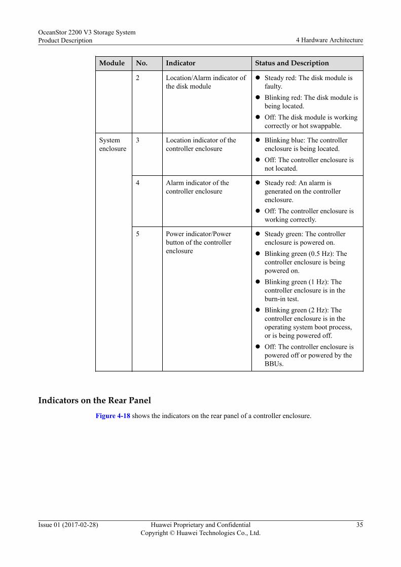
Indicators on the Rear PanelFigure 4-18 shows the indicators on the rear panel of a controller enclosure.
OceanStor 2200 V3 Storage SystemProduct Description 4 Hardware Architecture
Issue 01 (2017-02-28) Huawei Proprietary and ConfidentialCopyright © Huawei Technologies Co., Ltd.
35

Figure 4-18 Indicators on the rear panel of a controller enclosure
1 Power indicator of the interface module/Hot Swapbutton of the module
2 Link/Active/Mode indicator of the SmartIOport
3 Running/Alarm indicator of the power module 4 Link/Active indicator of the managementnetwork port
5 Speed indicator of the management network port 6 Running/Alarm indicator of the backup powermodule
7 Power indicator of the controller 8 Alarm indicator of the controller
9 Indicator of the mini SAS HD expansion port 10 Link/Active indicator of the GE electrical port
11 Speed indicator of the GE electrical port
Table 4-9 describes the indicators on the rear panel of the controller enclosure.
Table 4-9 Description of the indicators on the rear panel of a controller enclosure
Module No. Indicator Status and Description
Interfacemodule
1 Powerindicator ofthe interfacemodule/HotSwap buttonof themodule
l Steady green: The interface module is runningproperly.
l Blinking green: The interface module receives ahot swap request.
l Steady red: The interface module is faulty.l Off: The interface module is powered off or can
be hot-swapped.
OceanStor 2200 V3 Storage SystemProduct Description 4 Hardware Architecture
Issue 01 (2017-02-28) Huawei Proprietary and ConfidentialCopyright © Huawei Technologies Co., Ltd.
36

Module No. Indicator Status and Description
2 Link/Active/Modeindicator ofthe SmartIOport
l Blinking blue slowly: The interface module isworking in FC mode, and the port link is down.
l Blinking blue quickly: The interface module isworking in FC mode, and data is beingtransmitted.
l Steady blue: The interface module is working inFC mode, the port link is up, and no data isbeing transmitted.
l Blinking green slowly: The interface module isworking in ETH mode, and the port link isdown.
l Blinking green quickly: The interface module isworking in ETH mode, and data is beingtransmitted.
l Steady green: The interface module is workingin ETH mode, the port link is up, and no data isbeing transmitted.
l Steady red: The port is faulty.l Blinking red: The port is being located.l Off: The port is not powered on.
Powermodule
3 Running/Alarmindicator ofthe powermodule
l Steady green: The power supply is correct.l Blinking green: The power input is normal but
the disk enclosure is powered off.l Steady red: The power module is faulty.l Off: No external power input is found.
Controller 4 Link/Activeindicator ofthemanagementnetwork port
l Steady green: The port is connected properly.l Blinking green: Data is being transferred.l Off: The port is connected abnormally.
5 Speedindicator ofthemanagementnetwork port
l Steady orange: Data is being transferred at thehighest rate.
l Off: The data transfer speed is lower than thehighest speed.
6 Running/Alarmindicator ofthe backuppowermodule
l Steady green: The backup power module isfully charged.
l Blinking green (1 Hz): The backup powermodule is being charged.
l Blinking green (4 Hz): The backup powermodule is being discharged.
l Steady red: The backup power module is faulty.
OceanStor 2200 V3 Storage SystemProduct Description 4 Hardware Architecture
Issue 01 (2017-02-28) Huawei Proprietary and ConfidentialCopyright © Huawei Technologies Co., Ltd.
37

Module No. Indicator Status and Description
7 Powerindicator ofthe controller
l Steady green: The controller is powered on.l Blinking green (0.5 Hz): The controller
enclosure is powered on and in the BIOS bootprocess.
l Blinking green (2 Hz): The controller is in theoperating system boot process, or the controlleris in the power-off process.
l Off: The controller is absent or powered off.
8 Alarmindicator ofthe controller
l Steady red: An alarm is generated on thecontroller.
l The Alarm indicator blinking red and the Powerindicator blinking green: The controller is beinglocated.
l Off: The controller is working correctly.
9 Indicator ofthe mini SASHDexpansionport
l Steady blue: Data is transferred to thedownstream disk enclosure at the rate of 4 x 12Gbit/s.
l Blinking blue: Data is being transferred to thedownstream disk enclosure at the rate of 4 x 12Gbit/s.
l Steady green: Data is transferred to thedownstream disk enclosure at the rate of 4 x 6Gbit/s or 4 x 3 Gbit/s.
l Blinking green: Data is being transferred to thedownstream disk enclosure at the rate of 4 x 6Gbit/s or 4 x 3 Gbit/s.
l Steady red: The port is faulty.l Off: The link to the port is down.
10 Link/Activeindicator ofthe GEelectricalport
l Steady green: The link to the application serveris normal.
l Blinking green: Data is being transferred.l Off: The link to the application server is down
or no link exists.
11 Speedindicator ofthe GEelectricalport
l Steady orange: The data transfer rate betweenthe storage system and the application server is1 Gbit/s.
l Off: The data transfer rate between the storagesystem and the application server is less than 1Gbit/s.
OceanStor 2200 V3 Storage SystemProduct Description 4 Hardware Architecture
Issue 01 (2017-02-28) Huawei Proprietary and ConfidentialCopyright © Huawei Technologies Co., Ltd.
38

4.3 2 U Disk Enclosure (2.5-Inch Disks)This chapter describes a disk enclosure in terms of its hardware structure, componentfunctions, front and rear views, and indicators.
4.3.1 OverviewThe disk enclosure consists of a system enclosure, expansion modules, disk modules, andpower modules.
Overall StructureFigure 4-19 shows the overall structure of a 2 U SAS disk enclosure.
Figure 4-19 Overall structure of a 2 U SAS disk enclosure with AC power modules
1 System enclosure 2 Disk module
3 Power module 4 Expansion module
Front viewFigure 4-20 shows the front view of a 2 U disk enclosure.
OceanStor 2200 V3 Storage SystemProduct Description 4 Hardware Architecture
Issue 01 (2017-02-28) Huawei Proprietary and ConfidentialCopyright © Huawei Technologies Co., Ltd.
39

Figure 4-20 Front view of a 2 U disk enclosure
1 Disk module latch 2 Disk module handle
3 ID display of the disk enclosure
NOTE
The disk slots are numbered 0 to 24 from left to right.
Rear ViewFigure 4-21 shows the rear view of a disk enclosure with the AC power module.
Figure 4-21 Rear view of a disk enclosure with the AC power module
1 Power module 2 Power module latch
3 Power module handle 4 Expansion module handle
5 Expansion module 6 Serial port
7 Mini SAS HD PRI expansion port 8 Mini SAS HD EXP expansion port
9 Disk enclosure ID display
4.3.2 Component DescriptionThis section provides the illustration and description of each component of the storagesystem.
4.3.2.1 System EnclosureThe system enclosure integrates a midplane in order to provide reliable connections forinterface modules and to distribute power and signals to inner modules.
AppearanceFigure 4-22 shows the appearance of a system enclosure.
OceanStor 2200 V3 Storage SystemProduct Description 4 Hardware Architecture
Issue 01 (2017-02-28) Huawei Proprietary and ConfidentialCopyright © Huawei Technologies Co., Ltd.
40

Figure 4-22 System enclosure
4.3.2.2 Expansion Module
An expansion module provides expansion ports for communication between the diskenclosure and the controller enclosure. Each expansion module provides a PRI expansion portand an EXP expansion port.
Appearance
Figure 4-23 shows the appearance of an expansion module.
Figure 4-23 Expansion module
OceanStor 2200 V3 Storage SystemProduct Description 4 Hardware Architecture
Issue 01 (2017-02-28) Huawei Proprietary and ConfidentialCopyright © Huawei Technologies Co., Ltd.
41

Ports
Figure 4-24 shows the ports of an expansion module.
Figure 4-24 Interfaces of an expansion module
1 Expansion module handle 2 Serial port
3 Alarm indicator of the expansion module 4 Power indicator of the expansion module
5 Indicator of the mini SAS HD expansion port 6 Mini SAS HD PRI expansion port
7 Mini SAS HD EXP expansion port 8 Disk enclosure ID display
Indicators
Table 4-10 describes indicators on an expansion module of a powered-on storage system.
Table 4-10 Indicators on an expansion module
No. Indicator Status and Description
3 Alarm indicator of theexpansion module
l Steady red: An alarm is generated in theexpansion module.
l Off: The expansion module is workingcorrectly.
4 Power indicator of theexpansion module
l Steady green: The expansion module ispowered on.
l Off: The expansion module is powered off.
5 Indicator of the miniSAS HD expansion port
l Steady blue: Data is transferred to thedownstream disk enclosure at the rate of 4 x12 Gbit/s.
l Blinking blue: Data is being transferred to thedownstream disk enclosure at the rate of 4 x12 Gbit/s.
l Steady green: Data is transferred to thedownstream disk enclosure at the rate of 4 x 6Gbit/s or 4 x 3 Gbit/s.
l Blinking green: Data is being transferred tothe downstream disk enclosure at the rate of 4x 6 Gbit/s or 4 x 3 Gbit/s.
l Steady red: The port is faulty.l Off: The link to the port is down.
OceanStor 2200 V3 Storage SystemProduct Description 4 Hardware Architecture
Issue 01 (2017-02-28) Huawei Proprietary and ConfidentialCopyright © Huawei Technologies Co., Ltd.
42

4.3.2.3 Power ModulePower modules can ensure that the disk enclosure works correctly in maximum powerconsumption mode.
AppearanceFigure 4-25 shows the appearance of an AC power module.
Figure 4-25 AC power module
1 Power module handle 2 Power module latch
3 Fan built in the power module 4 Power module socket
5 Running/Alarm indicator of the power module
IndicatorsTable 4-11 describes indicators on a power module of a powered-on storage system.
OceanStor 2200 V3 Storage SystemProduct Description 4 Hardware Architecture
Issue 01 (2017-02-28) Huawei Proprietary and ConfidentialCopyright © Huawei Technologies Co., Ltd.
43

Table 4-11 Indicators on a power module
No. Indicator Status and Description
5 Running/Alarm indicatorof the power module
l Steady green: The power supply is correct.l Blinking green: The power input is normal
but the disk enclosure is powered off.l Steady red: The power module is faulty.l Off: No external power input is found.
4.3.2.4 Disk Module
Disk modules provide storage capacity for a storage system. Disk modules can be used as asystem safe disk, and can save service data, system data, and cache data.
Appearance
Figure 4-26 shows the appearance of a disk module.
Figure 4-26 Disk module
1 Running indicator of the disk module 2 Alarm/Location indicator of the disk module
OceanStor 2200 V3 Storage SystemProduct Description 4 Hardware Architecture
Issue 01 (2017-02-28) Huawei Proprietary and ConfidentialCopyright © Huawei Technologies Co., Ltd.
44

3 Disk module latch 4 Disk module handle
5 Disk module label 6 Disk
7 Disk tray
Indicators
Table 4-12 describes indicators on a disk module of a powered-on storage system.
Table 4-12 Indicators on a disk module
No. Indicator Status and Description
1 Running indicator of thedisk module
l Steady green: The disk module is workingcorrectly.
l Blinking green: Data is being read and writtenon the disk module.
l Off: The disk module is powered off orpowered on incorrectly.
2 Alarm/Location indicatorof the disk module
l Steady red: The disk module is faulty.l Blinking red: The disk module is being
located.l Off: The disk module is working correctly or
hot swappable.
4.3.3 Indicator IntroductionAfter a disk enclosure is powered on, you can check the current operating status of the diskenclosure by viewing its indicators.
Indicators on the Front Panel
Figure 4-27 shows the indicators on the front panel of a disk enclosure.
Figure 4-27 Indicators on the front panel of a disk enclosure
1 Running indicator of the disk module 2 Location/Alarm indicator of the disk module
3 Location indicator of the disk enclosure 4 Alarm indicator of the disk enclosure
OceanStor 2200 V3 Storage SystemProduct Description 4 Hardware Architecture
Issue 01 (2017-02-28) Huawei Proprietary and ConfidentialCopyright © Huawei Technologies Co., Ltd.
45

5 Power indicator of the disk enclosure
Table 4-13 describes the indicators on the front panel of the disk enclosure.
Table 4-13 Description of the indicators on the front panel of a disk enclosure
Module No. Indicator Status and Description
Diskmodule
1 Running indicator of thedisk module
l Steady green: The disk moduleis working correctly.
l Blinking green: Data is beingread and written on the diskmodule.
l Off: The disk module ispowered off or powered onincorrectly.
2 Alarm/Location indicatorof the disk module
l Steady red: The disk module isfaulty.
l Blinking red: The disk moduleis being located.
l Off: The disk module isworking correctly or hotswappable.
Systemenclosure
3 Location indicator of thedisk enclosure
l Blinking blue: The diskenclosure is being located.
l Off: The disk enclosure is notlocated.
4 Alarm indicator of the diskenclosure
l Steady red: An alarm isgenerated in the disk enclosure.
l Off: The disk enclosure isworking correctly.
5 Power indicator of the diskenclosure
l Steady green: The diskenclosure is powered on.
l Off: The disk enclosure ispowered off.
Indicators on the Rear PanelFigure 4-28 shows the indicators on the rear panel of a disk enclosure.
OceanStor 2200 V3 Storage SystemProduct Description 4 Hardware Architecture
Issue 01 (2017-02-28) Huawei Proprietary and ConfidentialCopyright © Huawei Technologies Co., Ltd.
46

Figure 4-28 Indicators on the rear panel of a disk enclosure
1 Alarm indicator of the expansion module 2 Power indicator of the expansion module
3 Indicator of the mini SAS HD expansionport
4 Running/Alarm indicator of the powermodule
Table 4-14 describes the indicators on the rear panel of the disk enclosure.
Table 4-14 Description of the indicators on the rear panel of a disk enclosure
Module No. Indicator Status and Description
Expansionmodule
1 Alarmindicator oftheexpansionmodule
l Steady red: An alarm is generated on theexpansion module.
l Off: The expansion module is workingcorrectly.
2 Powerindicator oftheexpansionmodule
l Steady green: The expansion module ispowered on.
l Off: The expansion module is powered off.
3 Indicator ofthe miniSAS HDexpansionport
l Steady blue: Data is transferred to thedownstream disk enclosure at the rate of 4 x12 Gbit/s.
l Blinking blue: Data is being transferred to thedownstream disk enclosure at the rate of 4 x12 Gbit/s.
l Steady green: Data is transferred to thedownstream disk enclosure at the rate of 4 x 6Gbit/s or 4 x 3 Gbit/s.
l Blinking green: Data is being transferred tothe downstream disk enclosure at the rate of 4x 6 Gbit/s or 4 x 3 Gbit/s.
l Steady red: The port is faulty.l Off: The link to the port is down.
OceanStor 2200 V3 Storage SystemProduct Description 4 Hardware Architecture
Issue 01 (2017-02-28) Huawei Proprietary and ConfidentialCopyright © Huawei Technologies Co., Ltd.
47

Module No. Indicator Status and Description
Powermodule
4 Running/Alarmindicator ofthe powermodule
l Steady green: The power supply is correct.l Blinking green: The power input is normal but
the disk enclosure is powered off.l Steady red: The power supply is faulty.l Off: No external power input is found.
4.4 4 U Disk Enclosure (3.5-Inch Disks)This chapter describes a disk enclosure in terms of its hardware structure, componentfunctions, front and rear views, and indicators.
4.4.1 OverviewThe disk enclosure consists of a system enclosure, expansion modules, disk modules, andpower modules.
Overall Structure
Figure 4-29 shows the overall structure of a 4 U disk enclosure.
Figure 4-29 Overall structure of a 4 U disk enclosure
1 System enclosure 2 Disk module
3 Fan module 4 Power module
OceanStor 2200 V3 Storage SystemProduct Description 4 Hardware Architecture
Issue 01 (2017-02-28) Huawei Proprietary and ConfidentialCopyright © Huawei Technologies Co., Ltd.
48
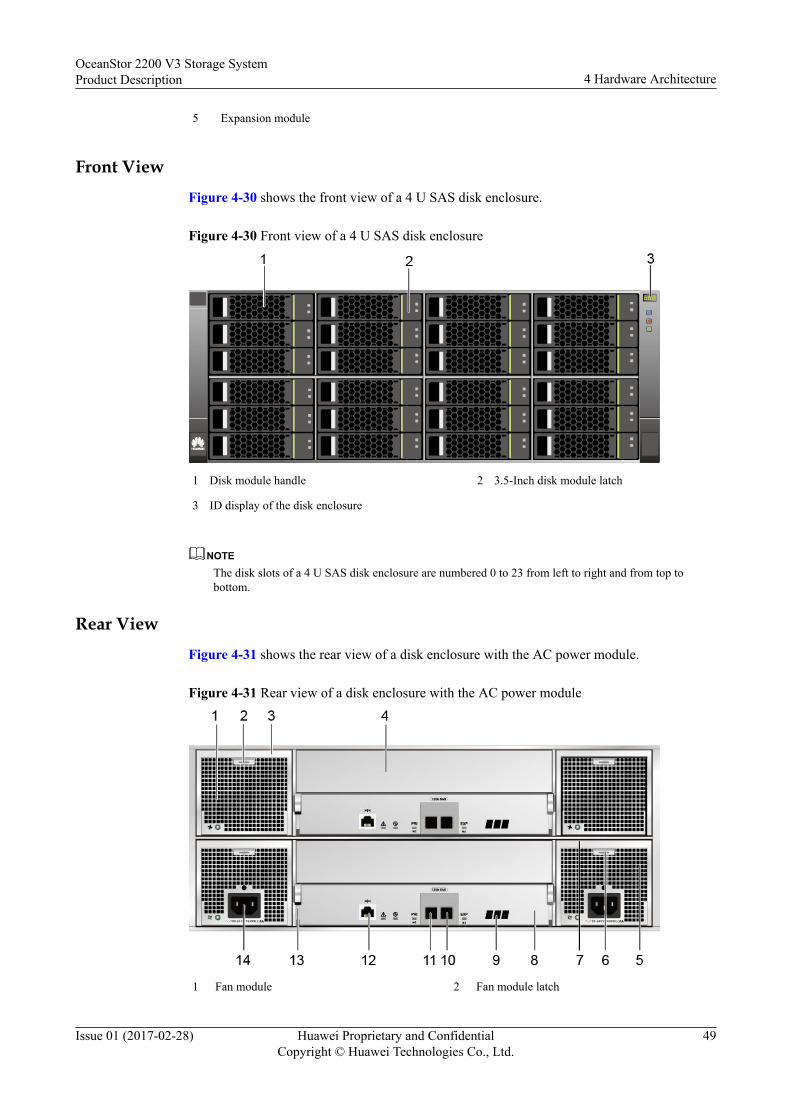
5 Expansion module
Front View
Figure 4-30 shows the front view of a 4 U SAS disk enclosure.
Figure 4-30 Front view of a 4 U SAS disk enclosure
1 Disk module handle 2 3.5-Inch disk module latch
3 ID display of the disk enclosure
NOTEThe disk slots of a 4 U SAS disk enclosure are numbered 0 to 23 from left to right and from top tobottom.
Rear View
Figure 4-31 shows the rear view of a disk enclosure with the AC power module.
Figure 4-31 Rear view of a disk enclosure with the AC power module
1 Fan module 2 Fan module latch
OceanStor 2200 V3 Storage SystemProduct Description 4 Hardware Architecture
Issue 01 (2017-02-28) Huawei Proprietary and ConfidentialCopyright © Huawei Technologies Co., Ltd.
49

3 Fan module handle 4 Filler panel
5 Power module 6 Power module latch
7 Power module handle 8 Expansion module
9 Disk enclosure ID display 10 Mini SAS HD EXP expansion port
11 Mini SAS HD PRI expansion port 12 Serial port
13 Expansion module handle 14 Power socket
4.4.2 Component DescriptionThis section provides the illustration and description of each component of the storagesystem.
4.4.2.1 System EnclosureThe system enclosure integrates a midplane in order to provide reliable connections forinterface modules and to distribute power and signals to inner modules.
AppearanceFigure 4-32 shows the appearance of a system enclosure.
Figure 4-32 System enclosure
OceanStor 2200 V3 Storage SystemProduct Description 4 Hardware Architecture
Issue 01 (2017-02-28) Huawei Proprietary and ConfidentialCopyright © Huawei Technologies Co., Ltd.
50

4.4.2.2 Expansion ModuleAn expansion module provides expansion ports for communication between the diskenclosure and the controller enclosure. Each expansion module provides a PRI expansion portand an EXP expansion port.
AppearanceFigure 4-33 shows the appearance of an expansion module.
Figure 4-33 Expansion module
PortsFigure 4-34 shows the ports of an expansion module.
Figure 4-34 Interfaces of an expansion module
1 Expansion module handle 2 Serial port
3 Alarm indicator of the expansion module 4 Power indicator of the expansion module
5 Indicator of the mini SAS HD expansion port 6 Mini SAS HD PRI expansion port
7 Mini SAS HD EXP expansion port 8 Disk enclosure ID display
IndicatorsTable 4-15 describes indicators on an expansion module of a powered-on storage system.
OceanStor 2200 V3 Storage SystemProduct Description 4 Hardware Architecture
Issue 01 (2017-02-28) Huawei Proprietary and ConfidentialCopyright © Huawei Technologies Co., Ltd.
51

Table 4-15 Indicators on an expansion module
No. Indicator Status and Description
3 Alarm indicator of theexpansion module
l Steady red: An alarm is generated in theexpansion module.
l Off: The expansion module is workingcorrectly.
4 Power indicator of theexpansion module
l Steady green: The expansion module ispowered on.
l Off: The expansion module is powered off.
5 Indicator of the miniSAS HD expansion port
l Steady blue: Data is transferred to thedownstream disk enclosure at the rate of 4 x12 Gbit/s.
l Blinking blue: Data is being transferred to thedownstream disk enclosure at the rate of 4 x12 Gbit/s.
l Steady green: Data is transferred to thedownstream disk enclosure at the rate of 4 x 6Gbit/s or 4 x 3 Gbit/s.
l Blinking green: Data is being transferred tothe downstream disk enclosure at the rate of 4x 6 Gbit/s or 4 x 3 Gbit/s.
l Steady red: The port is faulty.l Off: The link to the port is down.
4.4.2.3 Power ModulePower modules can ensure that the disk enclosure works correctly in maximum powerconsumption mode.
AppearanceFigure 4-35 shows the appearance of an AC power module.
OceanStor 2200 V3 Storage SystemProduct Description 4 Hardware Architecture
Issue 01 (2017-02-28) Huawei Proprietary and ConfidentialCopyright © Huawei Technologies Co., Ltd.
52

Figure 4-35 AC power module
1 Power module handle 2 Power module latch
3 Fan built in the power module 4 Power module socket
5 Running/Alarm indicator of the power module
Indicators
Table 4-16 describes indicators on a power module of a powered-on storage system.
Table 4-16 Indicators on a power module
No. Indicator Status and Description
5 Running/Alarm indicatorof the power module
l Steady green: The power supply is correct.l Blinking green: The power input is normal
but the disk enclosure is powered off.l Steady red: The power module is faulty.l Off: No external power input is found.
4.4.2.4 Fan Module
A fan module provides heat dissipation and supports the normal running of the disk enclosurein maximum power consumption mode.
OceanStor 2200 V3 Storage SystemProduct Description 4 Hardware Architecture
Issue 01 (2017-02-28) Huawei Proprietary and ConfidentialCopyright © Huawei Technologies Co., Ltd.
53
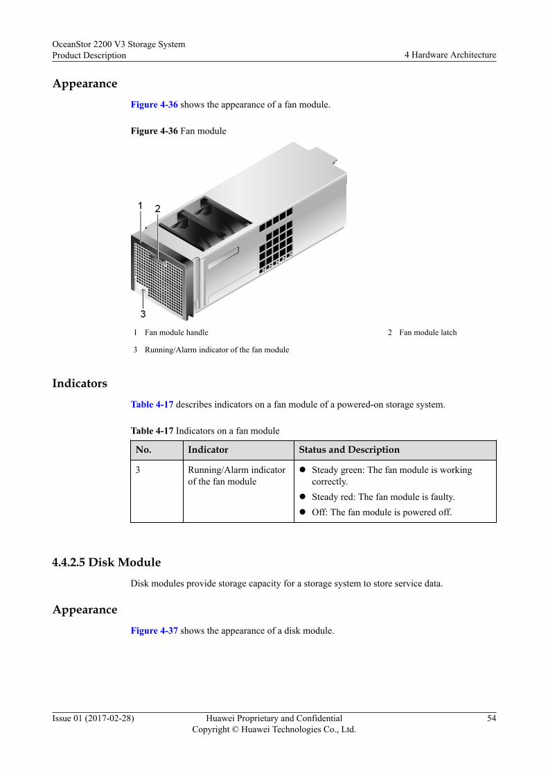
AppearanceFigure 4-36 shows the appearance of a fan module.
Figure 4-36 Fan module
1 Fan module handle 2 Fan module latch
3 Running/Alarm indicator of the fan module
IndicatorsTable 4-17 describes indicators on a fan module of a powered-on storage system.
Table 4-17 Indicators on a fan module
No. Indicator Status and Description
3 Running/Alarm indicatorof the fan module
l Steady green: The fan module is workingcorrectly.
l Steady red: The fan module is faulty.l Off: The fan module is powered off.
4.4.2.5 Disk ModuleDisk modules provide storage capacity for a storage system to store service data.
AppearanceFigure 4-37 shows the appearance of a disk module.
OceanStor 2200 V3 Storage SystemProduct Description 4 Hardware Architecture
Issue 01 (2017-02-28) Huawei Proprietary and ConfidentialCopyright © Huawei Technologies Co., Ltd.
54

Figure 4-37 Disk module
1 Disk module label 2 Disk module handle
3 Disk module latch 4 Alarm/Location indicator of the disk module
5 Running indicator of the disk module 6 Disk tray
7 Disk
IndicatorsTable 4-18 describes indicators on a disk module of a powered-on storage system.
Table 4-18 Indicators on a disk module
No. Indicator Status and Description
4 Alarm/Location indicatorof the disk module
l Steady red: The disk module is faulty.l Blinking red: The disk module is being
located.l Off: The disk module is working correctly or
hot swappable.
5 Running indicator of thedisk module
l Steady green: The disk module is workingcorrectly.
l Blinking green: Data is being read and writtenon the disk module.
l Off: The disk module is powered off orpowered on incorrectly.
OceanStor 2200 V3 Storage SystemProduct Description 4 Hardware Architecture
Issue 01 (2017-02-28) Huawei Proprietary and ConfidentialCopyright © Huawei Technologies Co., Ltd.
55

4.4.3 Indicator IntroductionAfter a disk enclosure is powered on, you can check the current operating status of the diskenclosure by viewing its indicators.
Indicators on the Front Panel
Figure 4-38 shows the indicators on the front panel of a disk enclosure.
Figure 4-38 Indicators on the front panel of a disk enclosure
1 Running indicator of the disk module 2 Location/Alarm indicator of the disk module
3 Location indicator of the disk enclosure 4 Alarm indicator of the disk enclosure
5 Power indicator of the disk enclosure
Table 4-19 describes the indicators on the front panel of the disk enclosure.
Table 4-19 Description of the indicators on the front panel of a disk enclosure
Module No. Indicator Status and Description
Diskmodule
1 Running indicator of thedisk module
l Steady green: The disk moduleis working correctly.
l Blinking green: Data is beingread and written on the diskmodule.
l Off: The disk module is poweredoff or powered on incorrectly.
2 Alarm/Location indicator ofthe disk module
l Steady red: The disk module isfaulty.
l Blinking red: The disk module isbeing located.
l Off: The disk module is workingcorrectly or hot swappable.
OceanStor 2200 V3 Storage SystemProduct Description 4 Hardware Architecture
Issue 01 (2017-02-28) Huawei Proprietary and ConfidentialCopyright © Huawei Technologies Co., Ltd.
56

Module No. Indicator Status and Description
Systemenclosure
3 Location indicator of thedisk enclosure
l Blinking blue: The diskenclosure is being located.
l Off: The disk enclosure is notlocated.
4 Alarm indicator of the diskenclosure
l Steady red: An alarm isgenerated in the disk enclosure.
l Off: The disk enclosure isworking correctly.
5 Power indicator of the diskenclosure
l Steady green: The disk enclosureis powered on.
l Off: The disk enclosure ispowered off.
Indicators on the Rear PanelFigure 4-39 shows the indicators on the rear panel of a disk enclosure.
Figure 4-39 Indicators on the rear panel of a disk enclosure
1 Running/Alarm indicator of the fan module 2 Running/Alarm indicator of the power module
3 Mini SAS HD expansion port indicator 4 Power indicator of the expansion module
5 Alarm indicator of the expansion module
Table 4-20 describes the indicators on the rear panel of the disk enclosure.
OceanStor 2200 V3 Storage SystemProduct Description 4 Hardware Architecture
Issue 01 (2017-02-28) Huawei Proprietary and ConfidentialCopyright © Huawei Technologies Co., Ltd.
57

Table 4-20 Description of the indicators on the rear panel of a disk enclosure
Module No. Indicator Status and Description
Fanmodule
1 Running/Alarmindicator ofthe fanmodule
l Steady green: The fan module is workingcorrectly.
l Steady red: The fan module is faulty.l Off: The fan module is powered off.
Powermodule
2 Running/Alarmindicator ofthe powermodule
l Steady green: The power supply is correct.l Blinking green: The power input is normal but
the disk enclosure is powered off.l Steady red: The power supply is faulty.l Off: No external power input is found.
Expansionmodule
3 Indicator ofthe miniSAS HDexpansionport
l Steady blue: Data is transferred to thedownstream disk enclosure at the rate of 4 x 12Gbit/s.
l Blinking blue: Data is being transferred to thedownstream disk enclosure at the rate of 4 x 12Gbit/s.
l Steady green: Data is transferred to thedownstream disk enclosure at the rate of 4 x 6Gbit/s or 4 x 3 Gbit/s.
l Blinking green: Data is being transferred to thedownstream disk enclosure at the rate of 4 x 6Gbit/s or 4 x 3 Gbit/s.
l Steady red: The port is faulty.l Off: The link to the port is down.
4 Powerindicator oftheexpansionmodule
l Steady green: The expansion module ispowered on.
l Off: The expansion module is powered off.
5 Alarmindicator oftheexpansionmodule
l Steady red: An alarm is generated on theexpansion module.
l Off: The expansion module is workingcorrectly.
4.5 Device CablesDevice cables used in the storage system include power cables, ground cables, and signalcables. This chapter displays the views and describes the functions and specifications ofvarious cables.
OceanStor 2200 V3 Storage SystemProduct Description 4 Hardware Architecture
Issue 01 (2017-02-28) Huawei Proprietary and ConfidentialCopyright © Huawei Technologies Co., Ltd.
58

4.5.1 Power CablesPower cables are classified into DC power cables, AC power cables and PDU power cables.Power cables supply power to devices in a cabinet. One end of a power cable is connected tothe power socket of the storage system, and the other end to an external power supply.
DC power scenarioEach DC power module is equipped with two DC power cables. Power cables supply powerto devices in a cabinet. One end of a power cable is connected to the power socket of a device,and the other end to an external power supply. Figure 4-40 shows the appearance of DCpower cables.
Figure 4-40 DC power cable
NOTE
Connect the black cable to the positive pole of the battery (+) and the blue cable to the negative pole (-).
AC power scenario
l Each AC power module is equipped with one AC power cable. Power cables supplypower to devices in a cabinet. One end of a power cable is connected to the power socketof a device, and the other end to an external power supply. Figure 4-41 shows theappearance of an AC power cable.
Figure 4-41 AC power cable
l If a cabinet is equipped with power distribution units (PDUs), use PDU power cables to
supply power to devices in the cabinet. Figure 4-42 shows the appearance of a PDUpower cable.
OceanStor 2200 V3 Storage SystemProduct Description 4 Hardware Architecture
Issue 01 (2017-02-28) Huawei Proprietary and ConfidentialCopyright © Huawei Technologies Co., Ltd.
59
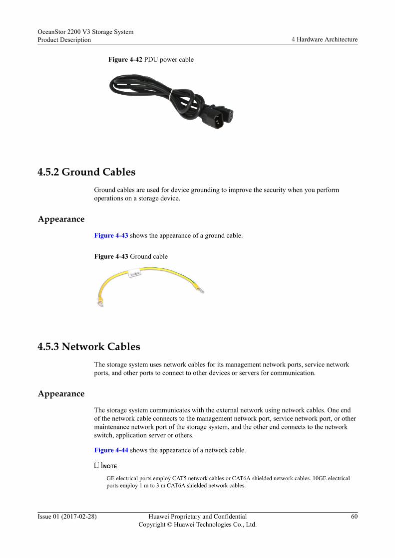
Figure 4-42 PDU power cable
4.5.2 Ground CablesGround cables are used for device grounding to improve the security when you performoperations on a storage device.
Appearance
Figure 4-43 shows the appearance of a ground cable.
Figure 4-43 Ground cable
4.5.3 Network CablesThe storage system uses network cables for its management network ports, service networkports, and other ports to connect to other devices or servers for communication.
Appearance
The storage system communicates with the external network using network cables. One endof the network cable connects to the management network port, service network port, or othermaintenance network port of the storage system, and the other end connects to the networkswitch, application server or others.
Figure 4-44 shows the appearance of a network cable.
NOTE
GE electrical ports employ CAT5 network cables or CAT6A shielded network cables. 10GE electricalports employ 1 m to 3 m CAT6A shielded network cables.
OceanStor 2200 V3 Storage SystemProduct Description 4 Hardware Architecture
Issue 01 (2017-02-28) Huawei Proprietary and ConfidentialCopyright © Huawei Technologies Co., Ltd.
60

Figure 4-44 Network cable
4.5.4 Serial CablesSerial cables are used to connect the serial ports of the storage system to other devices.
Appearance
A serial cable connects the serial port of the storage system to the port of the maintenanceterminal.
One end of a serial cable is the RJ-45 port used to connect to the serial port of a storagesystem. The other end is a DB-9 port used to connect to the port of the maintenance terminal.
Figure 4-45 shows the appearance of a serial cable.
Figure 4-45 Serial cable
4.5.5 Mini SAS HD CablesMini SAS HD cables are used to connect expansion ports. Mini SAS HD cables are dividedinto mini SAS HD electrical cables and mini SAS HD optical cables.
4.5.5.1 Mini SAS HD Electrical Cables
Mini SAS HD electrical cables are used to connect a controller enclosure to a disk enclosureor connect two disk enclosures.
Figure 4-46 shows the appearance of a mini SAS HD electrical cable.
OceanStor 2200 V3 Storage SystemProduct Description 4 Hardware Architecture
Issue 01 (2017-02-28) Huawei Proprietary and ConfidentialCopyright © Huawei Technologies Co., Ltd.
61
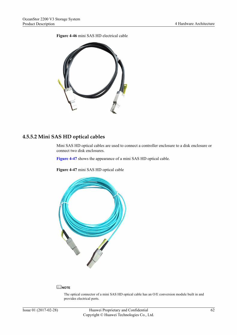
Figure 4-46 mini SAS HD electrical cable
4.5.5.2 Mini SAS HD optical cablesMini SAS HD optical cables are used to connect a controller enclosure to a disk enclosure orconnect two disk enclosures.
Figure 4-47 shows the appearance of a mini SAS HD optical cable.
Figure 4-47 mini SAS HD optical cable
NOTE
The optical connector of a mini SAS HD optical cable has an O/E conversion module built in andprovides electrical ports.
OceanStor 2200 V3 Storage SystemProduct Description 4 Hardware Architecture
Issue 01 (2017-02-28) Huawei Proprietary and ConfidentialCopyright © Huawei Technologies Co., Ltd.
62

4.5.6 Optical FibersThe storage system communicates with Fibre Channel switches through optical fibers. Oneend of the optical fiber connects to the Fibre Channel host bus adapter (HBA), and the otherend connects to the Fibre Channel switch or the application server. The two ends of the opticalfiber are LC connectors.
Figure 4-48 shows the appearance of optical fiber.
NOTE
When connecting cables, select proper cables according to site requirements and label information.
Figure 4-48 Optical Fiber
OceanStor 2200 V3 Storage SystemProduct Description 4 Hardware Architecture
Issue 01 (2017-02-28) Huawei Proprietary and ConfidentialCopyright © Huawei Technologies Co., Ltd.
63

5 Software Architecture
Storage system software manages the storage devices and the data stored, and assistsapplication servers in data operations.
The software suite provided by OceanStor 2200 V3 storage system consists of softwarerunning on a storage system, software running on a maintenance terminal, and softwarerunning on an application server. These three types of software work jointly to deliver storage,backup, and disaster recovery services in a smart, efficient, and cost-effective manner.
Figure 5-1 shows the storage system software architecture.
OceanStor 2200 V3 Storage SystemProduct Description 5 Software Architecture
Issue 01 (2017-02-28) Huawei Proprietary and ConfidentialCopyright © Huawei Technologies Co., Ltd.
64

Figure 5-1 Storage system software architecture
Software running on a maintenance terminal
Software running on a storage system
Operating system layer of a storage system
Value-added function control softwareBasic function control software
Software running on an application server (SAN)
Management network port/serial port
Fibre Channel/iSCSI channel
Cache
SCSI
Operating system layer of a management host
Operating system layer of a SAN host
SRAID
SPool
OceanStorToolkit
OceanStorSystemReporter
OceanStorCloud Service
OceanStorReplicationDirector
UItraPath
eSDK OceanStor
Snapshot
SmartThin
Remote replication
SmartQoS
LUN copy
SmartTier
Clone Consistency group
SmartMotion SmartCache
SmartErase
SmartMigration SmartVirtualization
HyperMirror
Management function control software
OceanStor DeviceManager SNMP CLI Syslog
Table 5-1 describes the storage system software architecture.
Table 5-1 Description of storage system software architecture
Software Function
Software runningon a storagesystem
The dedicated operating system manages storage system hardwareand supports the running of storage service software. The basicfunction control software provides basic data storage and accessfunctions. The value-added function control software providesadvanced functions such as backup, disaster recovery, andperformance tuning. The management function control softwareprovides the management utilities to the storage system.
OceanStor 2200 V3 Storage SystemProduct Description 5 Software Architecture
Issue 01 (2017-02-28) Huawei Proprietary and ConfidentialCopyright © Huawei Technologies Co., Ltd.
65

Software Function
Software runningon a maintenanceterminal
Configures and maintains the storage system. The software includesOceanStor Toolkit, OceanStor SystemReporter and OceanStor CloudService.
Software runningon an applicationserver (SAN)
On a SAN network, software running on an application server enablesthe application server to communicate and cooperate with the storagesystem. This software category includes BCManager, UltraPath, andeSDK OceanStor.
Table 5-2 describes the software running on a storage system.
Table 5-2 Description of software running on a storage system
Software Set Software Function
Storage systemoperating system
- Manages storage system hardware andsupports the running of storage servicesoftware.
Managementfunction controlsoftware
DeviceManager The DeviceManager is an integrated storagemanagement platform developed byHuawei. The DeviceManager provides easyconfiguration, management, andmaintenance of storage devices.
SNMPab The storage system can be connected tothird-party management software using theSNMP protocol. In addition, the storagesystem provides the functions supported bythe third-party management software usingthe MIB interface. A variety of networkmanagement software supports SNMP.Users can choose the software based on theirrequirements.
CLIc The OceanStor 2200 V3 storage systemsupports CLI-based management andconfiguration. Users can use a third-partyterminal software to log in to the OceanStor2200 V3 storage system through its serialport or management network port (overSSH), and manage the storage system on theCLI.
Syslog The storage system can send alarminformation to a third party. Syslog softwareis used to receive and save the information.There are a variety of third-party Syslogsoftware, and users can choose one based onsite requirements.
OceanStor 2200 V3 Storage SystemProduct Description 5 Software Architecture
Issue 01 (2017-02-28) Huawei Proprietary and ConfidentialCopyright © Huawei Technologies Co., Ltd.
66
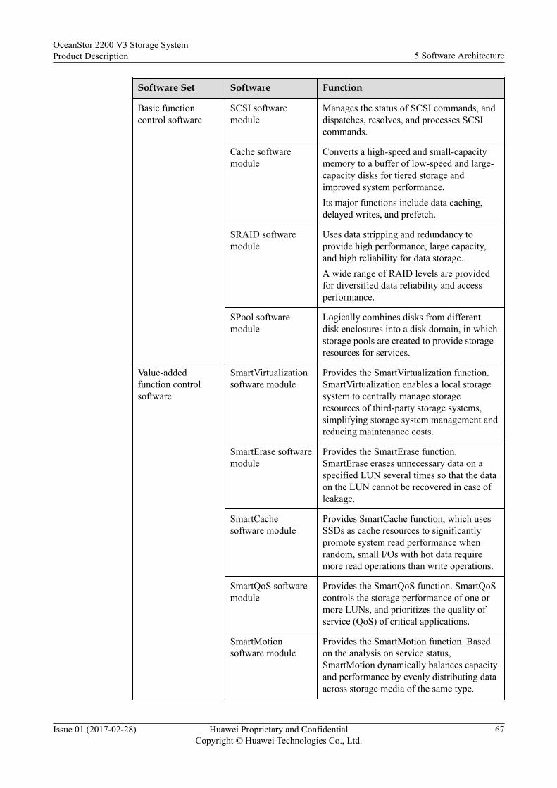
Software Set Software Function
Basic functioncontrol software
SCSI softwaremodule
Manages the status of SCSI commands, anddispatches, resolves, and processes SCSIcommands.
Cache softwaremodule
Converts a high-speed and small-capacitymemory to a buffer of low-speed and large-capacity disks for tiered storage andimproved system performance.Its major functions include data caching,delayed writes, and prefetch.
SRAID softwaremodule
Uses data stripping and redundancy toprovide high performance, large capacity,and high reliability for data storage.A wide range of RAID levels are providedfor diversified data reliability and accessperformance.
SPool softwaremodule
Logically combines disks from differentdisk enclosures into a disk domain, in whichstorage pools are created to provide storageresources for services.
Value-addedfunction controlsoftware
SmartVirtualizationsoftware module
Provides the SmartVirtualization function.SmartVirtualization enables a local storagesystem to centrally manage storageresources of third-party storage systems,simplifying storage system management andreducing maintenance costs.
SmartErase softwaremodule
Provides the SmartErase function.SmartErase erases unnecessary data on aspecified LUN several times so that the dataon the LUN cannot be recovered in case ofleakage.
SmartCachesoftware module
Provides SmartCache function, which usesSSDs as cache resources to significantlypromote system read performance whenrandom, small I/Os with hot data requiremore read operations than write operations.
SmartQoS softwaremodule
Provides the SmartQoS function. SmartQoScontrols the storage performance of one ormore LUNs, and prioritizes the quality ofservice (QoS) of critical applications.
SmartMotionsoftware module
Provides the SmartMotion function. Basedon the analysis on service status,SmartMotion dynamically balances capacityand performance by evenly distributing dataacross storage media of the same type.
OceanStor 2200 V3 Storage SystemProduct Description 5 Software Architecture
Issue 01 (2017-02-28) Huawei Proprietary and ConfidentialCopyright © Huawei Technologies Co., Ltd.
67

Software Set Software Function
SmartThin softwaremoduled
Provides the SmartThin function. SmartThinachieves the on-demand space allocation. Itallocates free storage space in quota toapplication servers only as needed,increasing the storage space usage.
SmartTier softwaremoduled
Provides the SmartTier function. SmartTierperiodically detects hotspot data per unittime, and promotes them from low-speedstorage media to high-speed one, boostingthe system performance at an affordablecost.
SmartMigrationsoftware moduled
Provides the SmartMigration function.SmartMigration migrates services on asource LUN transparently to a target LUNwithout interrupting host services. After themigration, the target LUN can replace thesource LUN to carry the services.
HyperMirrormoduled
Provides the HyperMirror function.HyperMirror backs up data in real time. Ifthe source data becomes unavailable,applications can automatically use the datacopy, ensuring high data security andapplication continuity.
Snapshot softwaremoduled
Provides the snapshot function. Snapshotdoes not provide a complete physicalduplicate but only an image of the sourcedata, and locates the image through amapping table.
Remote replicationsoftware moduled
Provides the remote replication function.Remote replication creates an available dataduplicate almost in real time on a storagesystem that resides in a different region fromthe local storage system. The duplicate canbe used immediately without data recovery,protecting service continuity and dataavailability to the maximum.
LUN copy softwaremoduled
Provides the LUN copy function. LUN copycopies the source LUN data onto the targetLUN, addressing the requirements ofapplications such as tiered storage,application upgrade, and remote backup.
Clone softwaremoduled
Provides the clone function. Clone generatesa full data copy of the source data in thelocal storage system.
OceanStor 2200 V3 Storage SystemProduct Description 5 Software Architecture
Issue 01 (2017-02-28) Huawei Proprietary and ConfidentialCopyright © Huawei Technologies Co., Ltd.
68

Software Set Software Function
Consistency groupsoftware moduled
Provides the consistency group function. Aconsistency group manages remotereplication tasks in batches. Any operationto the consistency group is also applied tothe remote replication tasks in the group,ensuring data consistency throughout thoseremote replication tasks.
a: Simple Network Management Protocolb: The supported character encoding is UTF-8.c: Command Line Interfaced: The single-controller OceanStor 2200 V3 not supported
Table 5-3 describes the software running on a maintenance terminal.
Table 5-3 Description of software running on a maintenance terminal
Software Function
OceanStor Toolkit OceanStor Toolkit helps service engineers and O&M engineersdeploy, maintain, and upgrade devices.
OceanStor CloudService
OceanStor Cloud Service is a piece of remote maintenance andmanagement software used for device monitoring, alarm reporting,and device inspection.
OceanStorSystemReporter
OceanStor SystemReporter is a dedicated performance and capacityreport analysis tool for the storage system.
Table 5-4 describes the software running on an application server.
Table 5-4 Description of software running on an application server (SAN)
Software Function
BCManager Provides data protection and disaster recovery for applicationservers based on the related storage system value-added features(synchronous/asynchronous remote replication, snapshot, LUNcopy, clone, HyperMetro, and HyperVault). It centrally managesthe requirements for data protection and disaster recoverybetween the storage system and application servers.
OceanStor 2200 V3 Storage SystemProduct Description 5 Software Architecture
Issue 01 (2017-02-28) Huawei Proprietary and ConfidentialCopyright © Huawei Technologies Co., Ltd.
69

Software Function
UltraPath A storage system driver program installed on application servers.When multiple data channels are set up between an applicationserver and a storage system, the UltraPath selects an optimalchannel for the application server to access the storage system.Therefore, UltraPath is an easy and efficient path managementsolution for proven data transmission reliability and high pathsecurity.
eSDK OceanStor eSDK OceanStor is a Huawei-developed integration platform forstorage devices. It has open capabilities and provides standardinterfaces and preinstalled plug-ins. The plug-ins and providersof eSDK OceanStor enable the storage system to interconnectwith vCenter and System Center so that customers can use theirexisting network management systems to manage Huawei'sstorage devices.
OceanStor 2200 V3 Storage SystemProduct Description 5 Software Architecture
Issue 01 (2017-02-28) Huawei Proprietary and ConfidentialCopyright © Huawei Technologies Co., Ltd.
70

6 Product Specifications
About This Chapter
This chapter describes the hardware specifications and software specifications of the storagesystem.
6.1 Hardware SpecificationsHardware specifications cover the hardware configuration, port specifications, diskspecifications, dimensions, weight, electrical specifications, and reliability specifications.
6.2 Software SpecificationsThe software specifications include the basic specifications, feature specifications,performance specifications, supported operating systems, and license control.
OceanStor 2200 V3 Storage SystemProduct Description 6 Product Specifications
Issue 01 (2017-02-28) Huawei Proprietary and ConfidentialCopyright © Huawei Technologies Co., Ltd.
71

6.1 Hardware SpecificationsHardware specifications cover the hardware configuration, port specifications, diskspecifications, dimensions, weight, electrical specifications, and reliability specifications.
Table 6-1 describes the hardware specification categories to help you quickly find out thespecification information you need.
Table 6-1 Description of hardware specification categories
Category Description
Hardwareconfiguration
Describes the configuration of major hardware components, such asprocessors, memory capacity, hard disks, and ports.
Portspecifications
Describes the port specifications, such as the maximum number ofports provided by each type of interface module and the maximumnumber of interface modules supported by each controller.
Diskspecifications
Describes the dimensions, rotational speed, capacity, and weight ofeach type of disk.
Dimensions andweight
Describes the dimensions and weight of controller enclosures and diskenclosures.
Electricalspecifications
Describes the electrical specifications of controller enclosures anddisk enclosures.
Reliabilityspecifications
Describes the reliability specifications of the storage system.
Hardware Configuration
Item Value
Processors per controller 1 x 16-core processor
Cache size per controller l 8 GBl 16 GB
Maximum number of controllers perenclosure
2 (single controller is available)
Maximum number of IP Scale-outcontrollers
2
Maximum number of disks 300
Controller enclosure configuration l 2 U controller enclosure with twenty-five2.5-inch disks
l 2 U controller enclosure with twelve 3.5-inch disks
OceanStor 2200 V3 Storage SystemProduct Description 6 Product Specifications
Issue 01 (2017-02-28) Huawei Proprietary and ConfidentialCopyright © Huawei Technologies Co., Ltd.
72
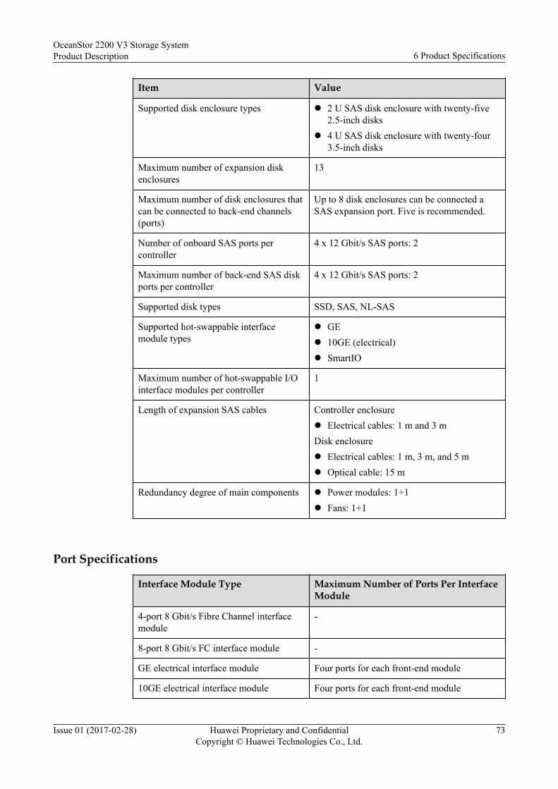
Item Value
Supported disk enclosure types l 2 U SAS disk enclosure with twenty-five2.5-inch disks
l 4 U SAS disk enclosure with twenty-four3.5-inch disks
Maximum number of expansion diskenclosures
13
Maximum number of disk enclosures thatcan be connected to back-end channels(ports)
Up to 8 disk enclosures can be connected aSAS expansion port. Five is recommended.
Number of onboard SAS ports percontroller
4 x 12 Gbit/s SAS ports: 2
Maximum number of back-end SAS diskports per controller
4 x 12 Gbit/s SAS ports: 2
Supported disk types SSD, SAS, NL-SAS
Supported hot-swappable interfacemodule types
l GEl 10GE (electrical)l SmartIO
Maximum number of hot-swappable I/Ointerface modules per controller
1
Length of expansion SAS cables Controller enclosurel Electrical cables: 1 m and 3 mDisk enclosurel Electrical cables: 1 m, 3 m, and 5 ml Optical cable: 15 m
Redundancy degree of main components l Power modules: 1+1l Fans: 1+1
Port Specifications
Interface Module Type Maximum Number of Ports Per InterfaceModule
4-port 8 Gbit/s Fibre Channel interfacemodule
-
8-port 8 Gbit/s FC interface module -
GE electrical interface module Four ports for each front-end module
10GE electrical interface module Four ports for each front-end module
OceanStor 2200 V3 Storage SystemProduct Description 6 Product Specifications
Issue 01 (2017-02-28) Huawei Proprietary and ConfidentialCopyright © Huawei Technologies Co., Ltd.
73

Interface Module Type Maximum Number of Ports Per InterfaceModule
SmartIO interface module Four ports per module for each front-end ornodes-interconnection module a
a: SmartIO interface modules support various ports including 16 Gbit/s Fibre Channelports, 8 Gbit/s Fibre Channel ports, 10 Gbit/s FCoE (VN2VF) ports, 10 Gbit/s Ethernetports, and iWARP (interconnection between scale-out nodes).
Port Type Max. Number of Ports Per Controller
8 Gbit/s Fibre Channel port 8
16 Gbit/s Fibre Channel port 4
GE porta 10b
10GE port 4
12 Gbit/s SAS expansion port 2
a: Onboard ports of the 2200 V3 are GE ports.b: includes two ports that can function as maintenance and service network ports, fouronboard front-end host ports, and four hot-swappable front-end host ports.
Disk Specifications
Disk Typea Dimensions
RotationalSpeed
Weight Capacity
SAS 2.5-inch 10,000 rpm 0.21 kg (0.46lb)
l 600 GBl 900 GBl 1.2 TBl 1.8 TB
15,000 rpm 0.21 kg (0.46lb)
l 600 GB
NL-SAS 3.5-inch 7200 rpm 0.72 kg (1.59lb)
l 2 TBl 4 TBl 6 TBl 8 TB
SSD 2.5-inch - 0.19 kg (0.42lb)
l 600 GBl 900 GBl 1.8 TBl 3.6 TB
3.5-inch 0.38 kg (0.84lb)
OceanStor 2200 V3 Storage SystemProduct Description 6 Product Specifications
Issue 01 (2017-02-28) Huawei Proprietary and ConfidentialCopyright © Huawei Technologies Co., Ltd.
74

Disk Typea Dimensions
RotationalSpeed
Weight Capacity
a: Restricted by the storage principles, SSDs and mechanical disks such as NL-SAS andSAS disks cannot be preserved for a long term while they are powered off.l SSDs where no data is stored can be preserved for a maximum of 12 months while they
are powered off. SSDs where data has been stored can be preserved for a maximum of 3months while they are powered off. If the maximum preservation time is exceeded, dataloss or SSD failure may occur.
l Packed mechanical disks can be preserved for a maximum of six months. Unpackedmechanical disks that are powered off can be preserved for a maximum of six monthstoo. If the maximum preservation time is exceeded, data loss or disk failure may occur.The maximum preservation time is determined based on the disk preservationspecifications provided by the mechanical disk vendor. For details about thespecifications, see the manual provided by the vendor.
Dimensions and Weight (unpackaged)
Module Parameter Value
Controller enclosure Dimensions l Depth: 488 mm (19.21 in.)l Width: 447 mm (17.60 in.)l Height: 86.1 mm (3.39 in.)
Weight (without disks) 15.9 kg (35.05 lb)
2 U SAS disk enclosure Dimensions l Depth: 488 mm (19.21 in.)l Width: 447 mm (17.60 in.)l Height: 86.1 mm (3.39 in.)
Weight (without disks) 13.3 kg (29.32 lb)
4 U SAS disk enclosure Dimensions l Depth: 488 mm (19.21 in.)l Width: 447 mm (17.60 in.)l Height: 175 mm (6.89 in.)
Weight (without disks) 26.5 kg (58.42 lb)
OceanStor 2200 V3 Storage SystemProduct Description 6 Product Specifications
Issue 01 (2017-02-28) Huawei Proprietary and ConfidentialCopyright © Huawei Technologies Co., Ltd.
75

Electrical Specifications
Item Value
Power consumption Controller enclosure 12 disk slotsl Max: 393 Wl Typical: 305 Wl Min: 284 W25 disk slotsl Max: 429 Wl Typical: 329 Wl Minimum: 212 W
2 U disk enclosure l Max: 268 Wl Typical: 215 Wl Minimum: 205 W
4 U disk enclosure l Max: 472 Wl Typical: 360 Wl Minimum: 340 W
Power voltage and ratedcurrency
Controller enclosure l AC: 100 V to 240 V, ±10%, 800W, 10 A
l High voltage DC (N/A for NorthAmerica and Canada): 240 V, 800W, 10 A
Disk enclosure l AC: 100 V to 240 V, ±10%, 800W, 10 A
l High voltage DC (N/A for NorthAmerica and Canada): 240 V, 800W, 10 A
AC power input type(socket type)
l AC: IEC60320-C14l High voltage DC: IEC60320-C14
Reliability Specifications
Item Value
Solution reliability 99.9999%
Mean Time Between Failures (MTBF) 1,000,000 hours
Mean Time To Repair (MTTR) 2 hours
OceanStor 2200 V3 Storage SystemProduct Description 6 Product Specifications
Issue 01 (2017-02-28) Huawei Proprietary and ConfidentialCopyright © Huawei Technologies Co., Ltd.
76
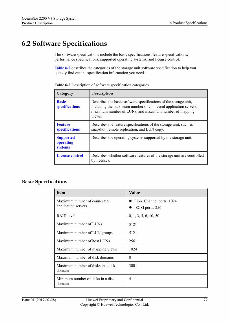
6.2 Software SpecificationsThe software specifications include the basic specifications, feature specifications,performance specifications, supported operating systems, and license control.
Table 6-2 describes the categories of the storage unit software specification to help youquickly find out the specification information you need.
Table 6-2 Description of software specification categories
Category Description
Basicspecifications
Describes the basic software specifications of the storage unit,including the maximum number of connected application servers,maximum number of LUNs, and maximum number of mappingviews.
Featurespecifications
Describes the feature specifications of the storage unit, such assnapshot, remote replication, and LUN copy.
Supportedoperatingsystems
Describes the operating systems supported by the storage unit.
License control Describes whether software features of the storage unit are controlledby licenses.
Basic Specifications
Item Value
Maximum number of connectedapplication servers
l Fibre Channel ports: 1024l iSCSI ports: 256
RAID level 0, 1, 3, 5, 6, 10, 50
Maximum number of LUNs 512a
Maximum number of LUN groups 512
Maximum number of host LUNs 256
Maximum number of mapping views 1024
Maximum number of disk domains 8
Maximum number of disks in a diskdomain
300
Minimum number of disks in a diskdomain
4
OceanStor 2200 V3 Storage SystemProduct Description 6 Product Specifications
Issue 01 (2017-02-28) Huawei Proprietary and ConfidentialCopyright © Huawei Technologies Co., Ltd.
77

Item Value
Maximum number of storage pools 8
Maximum number of LUNs in a storagepool
512a
Minimum capacity of a LUN 512 KB
Maximum capacity of a LUN 256 TB
a: the maximum number of LUNs, writable snapshots of LUNs, and VVols (PE LUNs andVVol LUNs)
Feature Specifications
Feature Parameter Value
HyperSnapa Maximum number of LUNsnapshots
256
Maximum number of sourceLUNs
128
Maximum number ofsnapshots for a source LUN
64
Maximum number of LUNsthat can be batch activated
64
LUN copy Maximum number of LUNcopies
32
Maximum number of targetLUNs for each source LUN
32
HyperClonea Maximum number of primaryLUNs
128
Maximum number ofsecondary LUNs
128
Maximum number ofsecondary LUNs in a clonegroup
8
Maximum number ofconsistent split pairs
64
HyperReplicationa Maximum number of pairs ina remote replication(synchronous +asynchronous)
128
OceanStor 2200 V3 Storage SystemProduct Description 6 Product Specifications
Issue 01 (2017-02-28) Huawei Proprietary and ConfidentialCopyright © Huawei Technologies Co., Ltd.
78

Feature Parameter Value
Maximum number ofsecondary LUNs in a pair
l Synchronous: 1:1l Asynchronous: 1:2
Maximum number ofconnected remote storagedevices
32
Maximum number of remotereplication consistencygroups
32 (synchronous+asynchronous)
Maximum number of pairs ina remote replicationconsistency group
32
SmartQoS Maximum number ofSmartQoS policies
128
Maximum number of LUNssupported by a policy
64
Number of priority levels 3
SmartTiera Maximum number of tiers 3
Migration granularity(configurable)
512 KB/1 MB/2 MB/4 MB/8MB/16 MB/32 MB/64 MB (4 MBby default)
SmartMotion Granularity 64 MB
SmartThina Maximum number of thinLUNs
512
Maximum capacity of a thinLUN
256 TB
Granularity of a thin LUN l WithoutSmartDedupe&SmartCompression: 64 KB fixed
l WithSmartDedupe&SmartCompression: 64 KB by default, 4 KB/8KB/16 KB/32 KB/64 KBadjustable on CLI
SmartMigrationa Maximum number of LUNsthat can be simultaneouslymigrated by a controller
8
Maximum number of LUNsfor which migration can beconfigured at a time
64
OceanStor 2200 V3 Storage SystemProduct Description 6 Product Specifications
Issue 01 (2017-02-28) Huawei Proprietary and ConfidentialCopyright © Huawei Technologies Co., Ltd.
79

Feature Parameter Value
Maximum number of LUNsfor which consistency splitcan be performed
64
SmartErase Maximum number of LUNswhose data can besimultaneously destructed byeach controller
8
SmartVirtualization Maximum number of externalLUNs
256
Maximum number of externalstorage arrays
32
Maximum number of pathsfor each external LUN
8
Maximum number ofmasqueraded external LUNs
512
Maximum number of externallinks that connect to arrays
256
Maximum number of externallinks that connect to arrays ona controller
128
HyperMirrora Maximum number of volumemirrors
64
Number of copies per volumemirror
2
SmartCache Total SSD cache capacity percontroller
200 GB (8 GB per controller)
Number of SSD cachepartitions for two controllersa
8 user partitions and a defaultcache partition
Data block granularity ofSSD cache
4 KB/8 KB/16 KB/32 KB/64KB/128 KB auto-adjust
a: The single-controller OceanStor 2200 V3 not supported
Performance Specifications
Item (For block service) Value
Maximum IOPS (full cache read hit) 600,000
Maximum bandwidth (MB/s) 4000
OceanStor 2200 V3 Storage SystemProduct Description 6 Product Specifications
Issue 01 (2017-02-28) Huawei Proprietary and ConfidentialCopyright © Huawei Technologies Co., Ltd.
80

Supported Operating Systems
Only the common operating systems supported by the storage systems are listed. For details,contact Huawei technical support engineers.
Operating System Version
Windows Mainstream Windows operating systems aresupported, including but not limited to thefollowing:l Windows Server 2003 R2 Standard SP2l Windows Server 2003 R2 Datacenter SP2l Windows Server 2003 R2 Enterprise
Edition SP2l Windows Server 2008 R2 Standard SP1l Windows Server 2008 R2 Datacenter SP1l Windows Server 2008 R2 Enterprise
Edition SP1l Windows Server 2012 Standardl Windows Server 2012 Datacenterl Windows Server 2012 Essentialsl Windows Server 2012 Foundation X64
Edition
Linux Mainstream Linux operating systems aresupported, including but not limited to thefollowing:l SUSE Linux Enterprise Server 10l SUSE Linux Enterprise Server 11l Red Hat Enterprise Server AS 5l Red Hat Enterprise Server AS 6
Other mainstream operating systems l HP-UX 11i v2l HP-UX 11i v3l AIX 6.1l AIX 7.1l Solaris 10 for Sparcl Solaris 11 for Sparcl VMware ESXi 4.1l VMware ESXi 5.0l Citrix XenServer 5.6l Citrix XenServer 6.0l MAC OS X 10.7l Other mainstream operating systems
OceanStor 2200 V3 Storage SystemProduct Description 6 Product Specifications
Issue 01 (2017-02-28) Huawei Proprietary and ConfidentialCopyright © Huawei Technologies Co., Ltd.
81

License Control
Function Requiring License Control or Not
HyperSnap (Snapshot) √a
HyperClone (Clone) √
HyperCopy (LUN Copy) √
HyperReplication (Remotereplication)
√b
SmartQoS √
SmartTier √
SmartMotion √
SmartThin √
SmartMigration √
SmartErase √
SmartVirtualization √
HyperMirror √
SmartCache √
a: HyperSnap for block and file services requires the same license. After purchasing andimporting the license file for the HyperSnap feature, a user can create snapshots for bothblock and file services.b: HyperReplication for block and file services requires the same license. After purchasingand importing the license file for the HyperReplication feature, a user can create remotereplications for both block and file services.
NOTE
As the OceanStor SystemReporter and OceanStor UltraPath are not deployed on a storage system, youcannot check them on the license management page of the storage system. To view purchased features,you can obtain the product authorization certificate from your dealer, which shows the purchasedfeatures.
Interoperability and Host ConnectivityYou can obtain the documentation for the interoperability and host connectivity of the storagesystem in the following ways:l Interoperability Navigator: In the OceanStor Interoperability Navigator, click the
components which you want to query to get the compatibility information.l Host Connectivity Guide: Visit the HUAWEI enterprise support website http://
support.huawei.com/enterprise and search Host Connectivity Guide.
OceanStor 2200 V3 Storage SystemProduct Description 6 Product Specifications
Issue 01 (2017-02-28) Huawei Proprietary and ConfidentialCopyright © Huawei Technologies Co., Ltd.
82
7 Environmental Requirements
About This Chapter
Environmental requirements cover the following aspects: temperature, humidity, particlecontaminants, corrosive airborne contaminants, heat dissipation, and noise.
7.1 Temperature, Humidity, and AltitudeTemperature, humidity, and altitude requirements must be met so that storage systems cancorrectly work or be properly preserved.
7.2 Vibration and ShockVibration and shock requirements must be met so that storage systems can correctly work orbe properly preserved.
7.3 Particle ContaminantsParticle contaminants and other negative environmental factors (such as abnormaltemperature and humidity) may expose IT equipment to a higher risks of corrosive failure.This clause specifies the limitation on particle contaminants with the aim at avoiding suchrisks.
7.4 Corrosive Airborne ContaminantsCorrosive airborne contaminants and other negative environmental factors (such as abnormaltemperature and humidity) may expose IT equipment to higher risks of corrosive failure. Thisarticle specifies the limitation on corrosive airborne contaminants with an aim at avoidingsuch risks.
7.5 Heat Dissipation and NoiseA storage system can run steadily using the heat dissipation system carried in its own fanmodules. An external device is necessary to remove the hot air discharged from a storagesystem into the equipment room to ensure proper air circulation.
OceanStor 2200 V3 Storage SystemProduct Description 7 Environmental Requirements
Issue 01 (2017-02-28) Huawei Proprietary and ConfidentialCopyright © Huawei Technologies Co., Ltd.
83

7.1 Temperature, Humidity, and AltitudeTemperature, humidity, and altitude requirements must be met so that storage systems cancorrectly work or be properly preserved.
Table 7-1 lists the temperature, humidity, and altitude requirements of the storage systems.
Table 7-1 Temperature, humidity, and altitude requirements of the storage systems
Parameter Condition Requirement
Temperature Operating temperature l 5°C to 40°C (41°F to 104°F) when thealtitude is between -60 m and +1800 m(-196.85 ft. and +5905.51 ft.)
l At altitudes between 1800 m and 3000 m(5905.51 ft. and 9842.52 ft.), thetemperature drops by 1°C (1.8°F) for 220 m(721.78 ft.) of altitude increase.
Operating temperaturechange rate
1°C (1.8°F)/minute
Non-operatingambient temperature
-40°C to +70°C (-40°F to +158°F)
Storage temperature(during transportationand storage withpackages)
-40°C to +70°C (-40°F to +158°F)
Humidity Operating humidity 10% RHa to 90% RH
Non-operatinghumidity
5% RH to 95% RH
Maximum humiditychange rate
10%/hour
Storage humidity(during transportationand storage withpackages)
5% RH to 95% RH
Altitude Operating altitude ofdisks
l HDDs: -304.8 m to +3048 m (-999.99 ft. to+9999.99 ft.)
l SSDs: -305 m to +3048 m (-1000.64 ft. to+9999.99 ft.)
Non-operating altitudeof disks
l HDDs: -305 m to +12192 m (-1000.64 ft. to+39999.51 ft.)
l SSDs: -305 m to +12192 m (-1000.64 ft. to+39999.51 ft.)
OceanStor 2200 V3 Storage SystemProduct Description 7 Environmental Requirements
Issue 01 (2017-02-28) Huawei Proprietary and ConfidentialCopyright © Huawei Technologies Co., Ltd.
84

Parameter Condition Requirement
a: RH, Relative Humidity
7.2 Vibration and ShockVibration and shock requirements must be met so that storage systems can correctly work orbe properly preserved.
Table 7-2 shows the vibration and shock requirements of storage systems.
Table 7-2 Vibration and shock requirements of storage systems
Parameter Requirement
Operating vibration 5 to 350 Hz, PSD: 0.0002 g2/Hz, 350 to 500 Hz, -3 dB,0.3 Grms, axial direction: 3 axes
Non-operating vibration 10 to 500 Hz, 1.49 Grms, 3 axes, 15 min/axisPSD:
l 10 [email protected]/HZ
l 20 [email protected]/HZ
l 50 [email protected]/HZ
l 100 [email protected]/HZ
l 500 [email protected]/HZ
Non-operating shock Half sine, 70 Gs/2 ms, 1 shock/face, total 6 faces
7.3 Particle ContaminantsParticle contaminants and other negative environmental factors (such as abnormaltemperature and humidity) may expose IT equipment to a higher risks of corrosive failure.This clause specifies the limitation on particle contaminants with the aim at avoiding suchrisks.
The concentration level of particle contaminants in a data center should meet the requirementslisted in the white paper entitled Gaseous and Particulate Contamination Guidelines for DataCenters published in 2011 by American Society of Heating Refrigerating and Air-conditioning Engineers (ASHRAE) Technical Committee (TC) 9.9.
ASHRAE, affiliated to International Organization for Standardization (ISO), is aninternational organization operated for the exclusive purpose of advancing the arts andsciences of heating, ventilation, air-conditioning, and refrigeration (HVAC & R). The Gaseousand Particulate Contamination Guidelines for Data Centers is widely accepted, which isprepared by the members of ASHRAE TC 9.9, AMD, Cisco, Cray, Dell, EMC, Hitachi, HP,IBM, Intel, Seagate, SGI, and Sun.
OceanStor 2200 V3 Storage SystemProduct Description 7 Environmental Requirements
Issue 01 (2017-02-28) Huawei Proprietary and ConfidentialCopyright © Huawei Technologies Co., Ltd.
85

According to the Guidelines, particle contaminants in a data center shall reach the cleanlinessof ISO 14664-1 Class 8:l Each cubic meter contains not more than 3,520,000 particles that are equal to or greater
than 0.5 μm.l Each cubic meter contains not more than 832,000 particles that are equal to or greater
than 1 μm.l Each cubic meter contains not more than 29,300 particles that are equal to or greater than
5 μm.It is recommended that you use an effective filter to process air flowing into the data center aswell as a filtering system to periodically clean the air already in the data center.
ISO 14644-1, Cleanrooms and Associated Controlled Environments - Part 1: Classification ofAir Cleanliness, is the primary global standard on air cleanliness classification. Table 7-3gives the air cleanliness classification by particle concentration.
Table 7-3 Air cleanliness classification by particle concentration of ISO 14664-1
ISOClass
Maximum allowable concentrations (particles/m3) for particles equalto and greater than the considered sizes shown below
≥ 0.1 μm ≥ 0.2 μm ≥ 0.3 μm ≥ 0.5 μm ≥ 1 μm ≥ 5 μm
Class 1 10 2 - - - -
Class 2 100 24 10 4 - -
Class 3 1000 237 102 35 8 -
Class 4 10,000 2,370 1,020 352 83 -
Class 5 100,000 23,700 10,200 3,520 832 29
Class 6 1,000,000 237,000 102,000 35,200 8,320 293
Class 7 - - - 352,000 83,200 2,930
Class 8 - - - 3,520,000 832,000 29,300
Class 9 - - - - 8,320,000 293,000
7.4 Corrosive Airborne ContaminantsCorrosive airborne contaminants and other negative environmental factors (such as abnormaltemperature and humidity) may expose IT equipment to higher risks of corrosive failure. Thisarticle specifies the limitation on corrosive airborne contaminants with an aim at avoidingsuch risks.
Table 7-4 lists common corrosive airborne contaminants and their sources.
OceanStor 2200 V3 Storage SystemProduct Description 7 Environmental Requirements
Issue 01 (2017-02-28) Huawei Proprietary and ConfidentialCopyright © Huawei Technologies Co., Ltd.
86

Table 7-4 Common corrosive airborne contaminants and their sources
Symbol Sources
H2S Geothermal emissions, microbiological activities, fossil fuelprocessing, wood rot, sewage treatment
SO2, SO3 Coal combustion, petroleum products, automobileemissions, ore smelting, sulfuric acid manufacture
S Foundries, sulfur manufacture, volcanoes
HF Fertilizer manufacture, aluminum manufacture, ceramicsmanufacture, steel manufacture, electronics devicemanufacture
NOX Automobile emissions, fossil fuel combustion, chemicalindustry
NH3 Microbiological activities, sewage, fertilizer manufacture,geothermal emissions, refrigeration equipment
C Incomplete combustion (aerosol constituent), foundry
CO Combustion, automobile emissions, microbiologicalactivities, tree rot
Cl2, ClO2 Chlorine manufacture, aluminum manufacture, zincmanufacture, refuse decomposition
HCl Automobile emissions, combustion, forest fire, oceanicprocesses, polymer combustion
HBr, HI Automobile emissions
O3 Atmospheric photochemical processes mainly involvingnitrogen oxides and oxygenated hydrocarbons
CNHN Automobile emissions, animal waste, sewage, tree rot
The concentration level of corrosive airborne contaminants in a data center should meet therequirements listed in the white paper entitled Gaseous and Particulate ContaminationGuidelines for Data Centers published in 2011 by the American Society of HeatingRefrigerating and Air-conditioning Engineers (ASHRAE) Technical Committee (TC) 9.9.
According to the Guidelines, corrosive airborne contaminants in a data center should meet thefollowing requirements:
l Copper corrosion rate
Less than 300 Å/month per ANSI/ISA-71.04-1985 severity level G1.
l Silver corrosion rate
Less than 200 Å/month.
NOTE
Å is a unit of length. One Å is equal to 1/10,000,000,000 meter.
OceanStor 2200 V3 Storage SystemProduct Description 7 Environmental Requirements
Issue 01 (2017-02-28) Huawei Proprietary and ConfidentialCopyright © Huawei Technologies Co., Ltd.
87

According to ANSI/ISA-71.04-1985 Environmental Conditions for Process Measurement andControl Systems: Airborne Contaminants, the gaseous corrosivity levels are G1 (mild), G2(moderate), G3 (harsh), and GX (severe), as described in Table 7-5.
Table 7-5 Gaseous corrosivity levels per ANSI/ISA-71.04-1985
SeverityLevel
Copper ReactivityLevel
Description
G1 (mild) 300 Å/month An environment sufficiently well-controlledsuch that corrosion is not a factor indetermining equipment reliability.
G2 (moderate) 300 Å/month to 1000Å/month
An environment in which the effects ofcorrosion are measurable and may be a factorin determining equipment reliability.
G3 (Harsh) 1000 Å/month to 2000Å/month
An environment in which there is highprobability that corrosion will occur.
GX (severe) > 2000 Å/month An environment in which only speciallydesigned and packaged equipment would beexpected to survive.
See Table 7-6 for the copper and silver corrosion rate requirements.
Table 7-6 Concentration limitation of corrosive airborne contaminants in a data center
Group Gas Unit Concentration
Group A H2S ppba < 3
SO2 ppb < 10
Cl2 ppb < 1
NO2 ppb < 50
Group B HF ppb < 1
NH3 ppb < 500
O3 ppb < 2
a: Parts per billion (ppb) is the number of units of mass of a contaminant per 1000 millionunits of total mass.
Group A and group B are common gas groups in a data center. The concentration limits ofGroup A or group B that correspond to copper reactivity level G1 are calculated based on thepremise that relative humidity in the data center is lower than 50% and that the gases in thegroup interact with each other. A 10% of increase in the relative humidity will heighten thegaseous corrosivity level by 1.
OceanStor 2200 V3 Storage SystemProduct Description 7 Environmental Requirements
Issue 01 (2017-02-28) Huawei Proprietary and ConfidentialCopyright © Huawei Technologies Co., Ltd.
88

Corrosion is not determined by a single factor, but by comprehensive environmental factorssuch as temperature, relative humidity, corrosive airborne contaminants, and ventilation. Anyof the environmental factors may affect the gaseous corrosivity level. Therefore, theconcentration limitation values specified in the previous table are for reference only.
7.5 Heat Dissipation and NoiseA storage system can run steadily using the heat dissipation system carried in its own fanmodules. An external device is necessary to remove the hot air discharged from a storagesystem into the equipment room to ensure proper air circulation.
Heat DissipationTraditional heat dissipation modes are as follows:l Air goes into a controller enclosure from the front end and out of its back end.
Cooling air enters through small holes on the interface modules. After dissipating theheat of interface modules, controllers, and power modules, the air is discharged by fans.The controller enclosure dynamically adjusts rotational speed of the fans based on theoperational temperature of the storage system.
l Air goes into a disk enclosure from the front end and out of its back end.Cooling air enters through the space between disks, passing the midplane, into the powermodules and expansion modules. After dissipating the heat, the air is discharged by fans.The disk enclosure dynamically adjusts rotational speed of the fans based on theoperational temperature of the storage system.
For better maintenance, ventilation, and heat dissipation, pay attention to the following wheninstalling the storage system in the cabinet:
l To ensure smooth ventilation, the cabinet should be at least 100 cm (39.4 inches) awayfrom the equipment room walls and at least 120 cm (47.24 inches) away from othercabinets (that are in front of or behind).
l To keep air convection between the cabinet and the equipment room, no enclosed spaceis allowed in the cabinet. 1 U (44.45 mm, 1.75 inches) space should be left above andbelow each device.
The airflow parameters of the storage system are shown in Table 7-7.
Table 7-7 Airflow parameters of storage systems
Device System Airflow
Controller enclosure l 75 CFMa (at max. fan speed)l 24 CFM (25℃)
2 U disk enclosure l 117 CFM (at max. fan speed)l 38 CFM (25℃)
4 U disk enclosure l 151 CFM (at max. fan speed)l 52 CFM (25℃)
a: CFM, Cubic Feet per Minute
OceanStor 2200 V3 Storage SystemProduct Description 7 Environmental Requirements
Issue 01 (2017-02-28) Huawei Proprietary and ConfidentialCopyright © Huawei Technologies Co., Ltd.
89
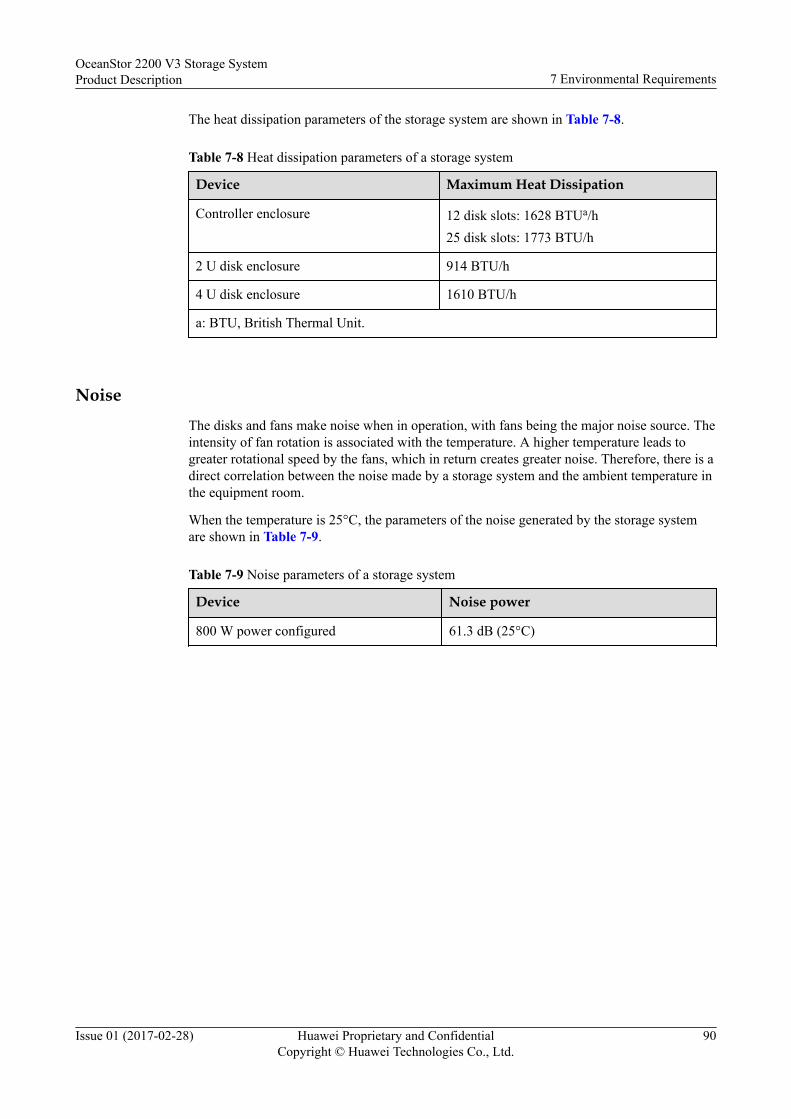
The heat dissipation parameters of the storage system are shown in Table 7-8.
Table 7-8 Heat dissipation parameters of a storage system
Device Maximum Heat Dissipation
Controller enclosure 12 disk slots: 1628 BTUa/h25 disk slots: 1773 BTU/h
2 U disk enclosure 914 BTU/h
4 U disk enclosure 1610 BTU/h
a: BTU, British Thermal Unit.
NoiseThe disks and fans make noise when in operation, with fans being the major noise source. Theintensity of fan rotation is associated with the temperature. A higher temperature leads togreater rotational speed by the fans, which in return creates greater noise. Therefore, there is adirect correlation between the noise made by a storage system and the ambient temperature inthe equipment room.
When the temperature is 25°C, the parameters of the noise generated by the storage systemare shown in Table 7-9.
Table 7-9 Noise parameters of a storage system
Device Noise power
800 W power configured 61.3 dB (25°C)
OceanStor 2200 V3 Storage SystemProduct Description 7 Environmental Requirements
Issue 01 (2017-02-28) Huawei Proprietary and ConfidentialCopyright © Huawei Technologies Co., Ltd.
90
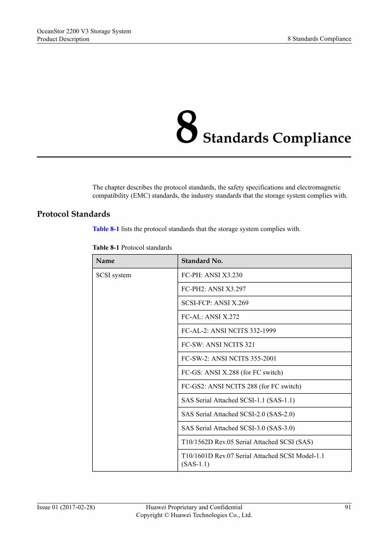
8 Standards Compliance
The chapter describes the protocol standards, the safety specifications and electromagneticcompatibility (EMC) standards, the industry standards that the storage system complies with.
Protocol StandardsTable 8-1 lists the protocol standards that the storage system complies with.
Table 8-1 Protocol standards
Name Standard No.
SCSI system FC-PH: ANSI X3.230
FC-PH2: ANSI X3.297
SCSI-FCP: ANSI X.269
FC-AL: ANSI X.272
FC-AL-2: ANSI NCITS 332-1999
FC-SW: ANSI NCITS 321
FC-SW-2: ANSI NCITS 355-2001
FC-GS: ANSI X.288 (for FC switch)
FC-GS2: ANSI NCITS 288 (for FC switch)
SAS Serial Attached SCSI-1.1 (SAS-1.1)
SAS Serial Attached SCSI-2.0 (SAS-2.0)
SAS Serial Attached SCSI-3.0 (SAS-3.0)
T10/1562D Rev.05 Serial Attached SCSI (SAS)
T10/1601D Rev.07 Serial Attached SCSI Model-1.1(SAS-1.1)
OceanStor 2200 V3 Storage SystemProduct Description 8 Standards Compliance
Issue 01 (2017-02-28) Huawei Proprietary and ConfidentialCopyright © Huawei Technologies Co., Ltd.
91
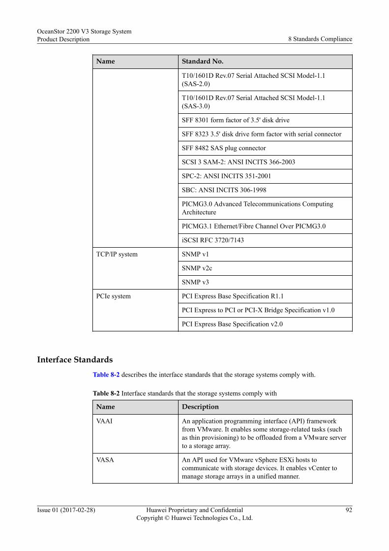
Name Standard No.
T10/1601D Rev.07 Serial Attached SCSI Model-1.1(SAS-2.0)
T10/1601D Rev.07 Serial Attached SCSI Model-1.1(SAS-3.0)
SFF 8301 form factor of 3.5' disk drive
SFF 8323 3.5' disk drive form factor with serial connector
SFF 8482 SAS plug connector
SCSI 3 SAM-2: ANSI INCITS 366-2003
SPC-2: ANSI INCITS 351-2001
SBC: ANSI INCITS 306-1998
PICMG3.0 Advanced Telecommunications ComputingArchitecture
PICMG3.1 Ethernet/Fibre Channel Over PICMG3.0
iSCSI RFC 3720/7143
TCP/IP system SNMP v1
SNMP v2c
SNMP v3
PCIe system PCI Express Base Specification R1.1
PCI Express to PCI or PCI-X Bridge Specification v1.0
PCI Express Base Specification v2.0
Interface StandardsTable 8-2 describes the interface standards that the storage systems comply with.
Table 8-2 Interface standards that the storage systems comply with
Name Description
VAAI An application programming interface (API) frameworkfrom VMware. It enables some storage-related tasks (suchas thin provisioning) to be offloaded from a VMware serverto a storage array.
VASA An API used for VMware vSphere ESXi hosts tocommunicate with storage devices. It enables vCenter tomanage storage arrays in a unified manner.
OceanStor 2200 V3 Storage SystemProduct Description 8 Standards Compliance
Issue 01 (2017-02-28) Huawei Proprietary and ConfidentialCopyright © Huawei Technologies Co., Ltd.
92

Name Description
SRA An interface between VMware Site Recovery Manager(SRM) and a storage system. It enables SRM to perform thefollowing operations: discovery of storage systems, non-disruptive failover test, emergency or planned failover,reverse replication, backup, and restoration.
SMI-S A storage standard developed and maintained by the StorageNetworking Industry Association (SNIA). It aims tosimplify the management of a storage area network (SAN)that contains devices from various manufacturers. Itprovides a universal management interface for all types ofnetwork elements and simplifies the management of aheterogeneous SAN environment.NOTE
Log in to http://support.huawei.com/enterprise/, in the searchfield, enter eSDK Storage, and select a path from the paths that areautomatically displayed to go to the document page. Search,browse, and download the SMI-S Provider documents of thecorresponding version to get more information.
ODX Offloaded data transfer (ODX) is a feature of WindowsServer 2012. The feature unloads files into storage arraysfor transmission. High transmission bandwidth betweenstorage arrays to largely shorten the data transmission delayand improve the data copy speed, while reduce the hostserver resource utilization rate.
Safety Specifications and EMC Standards
Table 8-3 lists the safety specifications and EMC standards that the storage system complieswith.
Table 8-3 Safety specifications and EMC standards
Name Standard No.
China safety standard GB 4943
North America safetystandard
UL 60950-1
European safety directive LVD 2006/95/EC
European safety standard EN 60950-1
China EMC standard GB9254-2008 (idt CISPR 22: 2006)
GB17625.1-2003 (idt IEC 61000-3-2: 2001)
Canada EMC standard ICES-003: 2004
CAN/CSA-CEI/IEC CISPR 22:02
OceanStor 2200 V3 Storage SystemProduct Description 8 Standards Compliance
Issue 01 (2017-02-28) Huawei Proprietary and ConfidentialCopyright © Huawei Technologies Co., Ltd.
93

Name Standard No.
North America EMCstandard
FCC, CFR 47 Part 15, Subpart B
European EMC directive EMC Directive 2004/108/EC
European EMC standard EN 55022
EN 55024
Industry Standards
Table 8-4 lists the industry standards that the storage system complies with.
Table 8-4 Industry standards
Name Standard No.
Ethernet IEEE 802.3
Fast Ethernet IEEE 802.3u
Gigabit Ethernet IEEE 802.3z
IEEE 802.3ab
10-Gigabit Ethernet IEEE 802.3ae
VLAN IEEE 802.1q
IEEE standard test accessport and boundary-scanarchitecture
IEEE 1149.1-2001
Procedure for failure modesand effects analysis(FMEA)
IEC 812
Presentation of reliability,maintainability andavailability predictions
IEC 863
ETSI standard(environment)
ETS 300 019
ETSI standard (power) ETS 300 132
ETSI standard (noise) ETS 300 753
ETSI standard(environment)
ETS 300 119
ETSI standard (grounding) ETS 300 253
ITUT standard (grounding) ITUT K.27
OceanStor 2200 V3 Storage SystemProduct Description 8 Standards Compliance
Issue 01 (2017-02-28) Huawei Proprietary and ConfidentialCopyright © Huawei Technologies Co., Ltd.
94

Name Standard No.
Environmental protection ECMA TR/70
Reliability GR-929, Telcordia SR-332
Clean room and relatedcontrolled environments
ISO 14664-1 Class8
Airborne contaminants andenvironment standards
ANSI/ISA-71.04-1985 severity level G1
OceanStor 2200 V3 Storage SystemProduct Description 8 Standards Compliance
Issue 01 (2017-02-28) Huawei Proprietary and ConfidentialCopyright © Huawei Technologies Co., Ltd.
95

9 Certifications
The chapter describes the certifications that the storage system passes.
Table 9-1 lists the certifications that the storage system passes.
Table 9-1 Certifications
Name Description
CB The IEC System for Conformity Testing and Certification of ElectricalEquipment (IECEE) is based on the use of specific IEC standards forelectrical equipment. The Certification Bodies (CB) Scheme is applicable toelectrical equipment within the scope of IEC standards for safety, acceptedfor use in the IECEE. The Scheme becomes operative for such standards assoon as at least one National Certification Body has declared their recognitionof CB Test Certificates. The CB scheme is designed for eliminating theinternational commerce barriers resulted from the compliance withcertifications and approval guidelines of different countries.The IEC System for Conformity Testing to Standards for Safety of ElectricalEquipment (referred to as the IECEE) is based on the use of specific IECstandards for electrical equipment. The CB Scheme is applicable to electricalequipment within the scope of IEC standards for safety, accepted for use inthe IECEE. The Scheme becomes operative for such standards as soon as atleast one National Certification Body has declared their recognition of CBTest Certificates.
CCC China Compulsory Certification (CCC) is a three-in-one authoritativecertification incorporating the Conformity Certification of ElectricalEquipment (CCEE), the certificate for the safe license of import granted byChina Commodity Inspection Bureau (CCIB), and Safety and ElectroMagnetic Compatibility (EMC).The China Compulsory Certificate (CCC) mainly involves the productsrelated to human health and security, animal and plant life and health,environmental protection, and public security.
OceanStor 2200 V3 Storage SystemProduct Description 9 Certifications
Issue 01 (2017-02-28) Huawei Proprietary and ConfidentialCopyright © Huawei Technologies Co., Ltd.
96

Name Description
FCC Federal Communications Commission (FCC) authorizes and manages all RFtransmission facilities and devices except for those used by the federalgovernment. It is also responsible for the environmental damages generatedby the facilities and devices it approves.
IC Industry Canada (IC) sets up the test standards for analog and digital terminaldevices and specifies corresponding EMC certificates that all importelectronic products must obtain.
UL Underwriters Laboratories Inc. (UL): The UL is a non-profit agency engagedin product safety testing.UL has its own certification system for the entire system, components, andmaterials. All electric products that are exported to the USA must pass the ULcertification.The UL safety certification is classified into the following three methods:l Labeling
The UL labeling service is the best known service of the UL safetycertification. The UL label on the product indicates that UL has tested thesample of the product according to the safety standards approved by theUSA. The sample does not cause fire, creepage, or other dangers ifpredictable.
l ClassificationUL tests the product according to different features, in the specifieddanger range, or under specific cases. In general, the classified productsare mostly construction materials or industrial instruments. The classifiedproducts include industrial or commercial products. Some specifiedfeatures must be tested, such as inflammability, hazardous performance, orspecifications specified by the government.
l ApprovalUL tests parts of the product or unfinished product. These parts will beused in the UL labeled product list. This service covers millions ofplastics, wires, circuit boards, various finished products, and even somelarge components, such as motorcycles or power supplies.
CE Conformite Europeenne (CE): Products marked with CE conform to EMC(2004/108/EC) and low-voltage (2006/95/EC) specifications published byEU.If this product has telecommunication functionality, the R_TTE Directive(1999/5/EC) that complies with the directives mentioned previously impliesconformity to the following European norms (in parentheses are theequivalent international standards and regulations):l EN 55022 (CISPR 22)-Electro Magnetic Interferencel EN 55024 (IEC61000-4-2, 3, 4, 5, 6, 8, 11)-Electro Magnetic Immunityl EN 60950 (IEC 60950)-Product Safety
OceanStor 2200 V3 Storage SystemProduct Description 9 Certifications
Issue 01 (2017-02-28) Huawei Proprietary and ConfidentialCopyright © Huawei Technologies Co., Ltd.
97

Name Description
REACH REACH is a set of comprehensive regulations that require all chemicalproducts that are both imported and produced in Europe must be registered,assessed, authorized, and restricted. In this way, customers can easilyrecognize the chemical elements. Thus, both humans and environment areprotected.
RoHS The restriction of the use of certain hazardous substances in electrical andelectronic equipment (RoHS) is the directive that restricts the use of certainhazardous substances in the electrical, electronic equipment.RoHS is an European Union (EU) compulsory standard that is designed toregulate the materials and the technical standard of the electrical andelectronic products. In this way, it does good to human health andenvironment protection. That is, the six hazardous substances of lead (Pb),mercury (Hg), cadmium (Cd), hexavalent chromium (Cr6+), polybrominatedbiphenyl (PBB), polybrominated diphenyl ethers (PBDE) can not exceed thespecified limits.
WEEE The EU Directive on Waste of Electric and Electronic Equipment. Electricaland electronic products sold in the EU market must comply with this directiveand have the mark of cross out wheeled bin.
GOST The national standard certification of Russia. Based on Russian ConsumerProtection Law, certain consumable products that are sold to Russia mustmeet the security, Electro Magnetic Interference (EMI), and sanitationrequirements. Based on the product certification and service laws, theproducts should be awarded the GOST certification.
C-TICK A mandatory certification issued by Australian Communications Authority(ACA) for communication equipment, mainly concerning EMC requirements.
SONCAP A certification issued by Standards Organization of Nigeria. The products inthe certification item list must acquire SONCAP for the entrance to Nigeriamarket.
OceanStor 2200 V3 Storage SystemProduct Description 9 Certifications
Issue 01 (2017-02-28) Huawei Proprietary and ConfidentialCopyright © Huawei Technologies Co., Ltd.
98

10 Operation and Maintenance
The storage systems can be operated and maintained by using the DeviceManager and thecommand-line interface (CLI), adapting to different environments and user habits.
Introduction to the DeviceManagerFigure 10-1 shows the DeviceManager main window.
Figure 10-1 DeviceManager main window
1
2
3
45
Table 10-1 describes the components of the DeviceManager main window.
OceanStor 2200 V3 Storage SystemProduct Description 10 Operation and Maintenance
Issue 01 (2017-02-28) Huawei Proprietary and ConfidentialCopyright © Huawei Technologies Co., Ltd.
99

Table 10-1 Components of the DeviceManager main window
No. Name Description
1 Function pane The function pane shows a page associated with thecurrent operation.
2 Status bar The status bar shows information such as the user namecurrently logged in and the login time.
3 Navigation bar The navigation bar shows the function modules of astorage system. Users can click a function module toconfigure the corresponding functions.
4 Exit, help, andlanguage selectionarea
This area displays an exit button, a help button, and alanguage selection button.
5 Fault statistics area The fault statistics area shows the number of each levelof system faults, helping users learn about the runningstatus of a storage system.
Users can log in to the DeviceManager by using a common browser.
To master GUI-based operations, you are advised to read this document and practice theoperations using the DeviceManager Demo. As a simulation program of storage systemmanagement software, the DeviceManager Demo simulates configuration and managementoperations on a storage system.
Introduction to the CLIThe CLI enables users to manage and maintain the V3 series storage systems using commandlines.
Users need to log in to the CLI by using terminal software, such as the HyperTerminalprovided by Windows, or PuTTY.
There are two ways to log in to the CLI.l Log in through a serial port of a storage system. To connect to a serial port, the
maintenance terminal must be located next to the storage system. Therefore, this loginmode is applicable to the scenario where a user does not know the management IPaddress of a storage system or a storage system is faulty.
l Log in through a management network port of a storage system. When there arereachable routes, a user can log in to the CLI by entering the IP address of themanagement network port of a storage system in the terminal software. IP networks areeasily accessible. Therefore, a user can log in to a storage system remotely, and this loginmode is more popular.
OceanStor 2200 V3 Storage SystemProduct Description 10 Operation and Maintenance
Issue 01 (2017-02-28) Huawei Proprietary and ConfidentialCopyright © Huawei Technologies Co., Ltd.
100

A How to Obtain Help
If a tough or critical problem persists in routine maintenance or troubleshooting, contactHuawei for technical support.
A.1 Preparations for Contacting HuaweiTo better solve the problem, you need to collect troubleshooting information and makedebugging preparations before contacting Huawei.
A.2 How to Use the DocumentHuawei provides guide documents shipped with the device. The guide documents can be usedto handle the common problems occurring in daily maintenance or troubleshooting.
A.3 How to Obtain Help from WebsiteHuawei provides users with timely and efficient technical support through the regionaloffices, secondary technical support system, telephone technical support, remote technicalsupport, and onsite technical support.
A.4 Ways to Contact HuaweiHuawei Technologies Co., Ltd. provides customers with comprehensive technical support andservice. For any assistance, contact our local office or company headquarters.
OceanStor 2200 V3 Storage SystemProduct Description A How to Obtain Help
Issue 01 (2017-02-28) Huawei Proprietary and ConfidentialCopyright © Huawei Technologies Co., Ltd.
101

A.1 Preparations for Contacting HuaweiTo better solve the problem, you need to collect troubleshooting information and makedebugging preparations before contacting Huawei.
A.1.1 Collecting Troubleshooting InformationYou need to collect troubleshooting information before troubleshooting.
You need to collect the following information:l Name and address of the customerl Contact person and telephone numberl Time when the fault occurredl Description of the fault phenomenal Device type and software versionl Measures taken after the fault occurs and the related resultsl Troubleshooting level and required solution deadline
A.1.2 Making Debugging PreparationsWhen you contact Huawei for help, the technical support engineer of Huawei might assist youto do certain operations to collect information about the fault or rectify the fault directly.
Before contacting Huawei for help, you need to prepare the boards, port modules,screwdrivers, screws, cables for serial ports, network cables, and other required materials.
A.2 How to Use the DocumentHuawei provides guide documents shipped with the device. The guide documents can be usedto handle the common problems occurring in daily maintenance or troubleshooting.
To better solve the problems, use the documents before you contact Huawei for technicalsupport.
A.3 How to Obtain Help from WebsiteHuawei provides users with timely and efficient technical support through the regionaloffices, secondary technical support system, telephone technical support, remote technicalsupport, and onsite technical support.
Contents of the Huawei technical support system are as follows:l Huawei headquarters technical support departmentl Regional office technical support centerl Customer service centerl Technical support website: http://support.huawei.com/enterprise/
You can query how to contact the regional offices at http://support.huawei.com/enterprise/.
OceanStor 2200 V3 Storage SystemProduct Description A How to Obtain Help
Issue 01 (2017-02-28) Huawei Proprietary and ConfidentialCopyright © Huawei Technologies Co., Ltd.
102
A.4 Ways to Contact HuaweiHuawei Technologies Co., Ltd. provides customers with comprehensive technical support andservice. For any assistance, contact our local office or company headquarters.
Huawei Technologies Co., Ltd.
Address: Huawei Industrial Base Bantian, Longgang Shenzhen 518129 People's Republic ofChina
Website: http://enterprise.huawei.com/
OceanStor 2200 V3 Storage SystemProduct Description A How to Obtain Help
Issue 01 (2017-02-28) Huawei Proprietary and ConfidentialCopyright © Huawei Technologies Co., Ltd.
103

B Glossary
If you want to obtain information about glossaries, visit http://support.huawei.com/enterprise/. In the search field, enter product model (such as 5500 V3), and select a path fromthe paths that are automatically displayed to go to the document page of the product. Browseor download the OceanStor V3 Series Storage Systems V300R006 Glossary.
OceanStor 2200 V3 Storage SystemProduct Description B Glossary
Issue 01 (2017-02-28) Huawei Proprietary and ConfidentialCopyright © Huawei Technologies Co., Ltd.
104

C Acronyms and Abbreviations
A
ANSI American National Standards Institute
B
BBU Backup Battery Unit
C
CLI Command Line Interface
E
ESN Equipment Serial Number
F
FC Fiber Channel
FC-AL Fiber Channel Arbitrated Loop
FCoE Fibre Channel over Ethernet
G
GUI Graphical User Interface
GE Gigabit Ethernet
H
HBA Host Bus Adapter
OceanStor 2200 V3 Storage SystemProduct Description C Acronyms and Abbreviations
Issue 01 (2017-02-28) Huawei Proprietary and ConfidentialCopyright © Huawei Technologies Co., Ltd.
105

HD High Density
I
IP Internet Protocol
ISA Instrument Society of America
iSCSI Internet Small Computer Systems Interface
ISO International Organization for Standardization
L
LUN Logical Unit Number
M
MTBF Mean Time Between Failure
MTTR Mean Time to Failure
N
NL-SAS Near Line Serial Attached SCSI
P
PDU Power Distribution Unit
U
USB Universal Serial Bus
R
RAID Redundant Array of Independent Disks
RSCN Registered State Change Notification
S
SAN Storage Area Network
SAS Serial Attached SCSI
SCSI Small Computer System Interface
OceanStor 2200 V3 Storage SystemProduct Description C Acronyms and Abbreviations
Issue 01 (2017-02-28) Huawei Proprietary and ConfidentialCopyright © Huawei Technologies Co., Ltd.
106

SSD Solid State Drive
V
VLAN Virtual LAN
VPN Virtual Private Network
OceanStor 2200 V3 Storage SystemProduct Description C Acronyms and Abbreviations
Issue 01 (2017-02-28) Huawei Proprietary and ConfidentialCopyright © Huawei Technologies Co., Ltd.
107