Embed Size (px)
Citation preview
PRODUCT DATA
Sound Sources and Impact Sound Source for Building Acoustics: Sound Sources: OmniSource™ Type 4295 and OmniPower™ Type 4292-LImpact Sound Source: Tapping Machine Type 3207Power Amplifiers Type 2734-A and 2734-BFor proper building acoustics measurements, a sound source whichfulfils the relevant standards (for example, ISO 140) is required.Brüel & Kjær offers a complete range of sound sources for buildingacoustics measurements, including Tapping Machine Type 3207,single-speaker omnidirectional OmniSource™ Type 4295 and 12-speaker omnidirectional OmniPower™ Type 4292-L. PowerAmplifier Type 2734 can drive both OmniPower and OmniSource.Optional carrying cases for the sound sources are available, as wellas wireless control systems for use with Hand-held Analyzer Type2250 and the dual channel Type 2270.
Uses and Features
Uses• Architectural and building acoustics• Measurement of:
– Airborne sound insulation– Reverberation time – Impact sound level
Features• Part of a complete building acoustics system featuring
Brüel & Kjær’s Hand-held Analyzer Type 2250 or 2270• Two omnidirectional noise sources• Tapping machine for impact sound level measurements• Remote operation via cable or wireless remote control• Satisfies national and international standards• Robust• Easily portable
Introduction
Architectural and building acoustic measurements require a range of noise sources for airborne noise andimpact noise transmission measurements.
For airborne noise transmission measurements, an omnidirectional sound source is needed. Brüel & Kjæroffers two solutions: OmniPower Sound Source Type 4292-L and OmniSource Sound Source Type 4295.
For impact sound measurements, Brüel & Kjær offers Tapping Machine Type 3207, a robust and portabledevice that fulfils national and international standards.
For a complete measurement system, combine the sound sources with a driving amplifier (such as Type2734-A or 2734-B), a sound level analyzer (such as Type 2250 or 2270), and a PC with Building Acousticanalysis and reporting software.
Brüel & Kjær supplies all of these items and a range of carrying cases for storage and transportation:• OmniPower Type 4292-L, 12-speaker high-power omnidirectional sound source• OmniSource Type 4295, lightweight single-speaker omnidirectional sound source• Tapping Machine Type 3207• Power Amplifier Type 2734-A or 2734-B, amplifiers for driving sound sources• Flight Case KE-0449 and Carrying Cases KE-0364 and KE-0392 for packing and transportation• Cables and Wireless Remote Control accessories• Battery Kit UA-1477 for Type 3207
Omnidirectional Sound Sources
For most building acoustics measurements, the sound source must radiate sound evenly in all directions togive reproducible and reliable results; therefore, the relevant building acoustics measurements standards(ISO 140 and ISO 3382) require the use of an omnidirectional sound source.
OmniPower Sound Source Type 4292-L
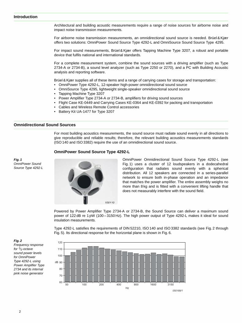
Fig. 1 OmniPower Sound Source Type 4292-L
OmniPower Omnidirectional Sound Source Type 4292-L (seeFig. 1) uses a cluster of 12 loudspeakers in a dodecahedralconfiguration that radiates sound evenly with a sphericaldistribution. All 12 speakers are connected in a series-parallelnetwork to ensure both in-phase operation and an impedancethat matches the power amplifier. The entire assembly weighs nomore than 8 kg and is fitted with a convenient lifting handle thatdoes not measurably interfere with the sound field.
Powered by Power Amplifier Type 2734-A or 2734-B, the Sound Source can deliver a maximum soundpower of 122 dB re 1 pW (100 – 3150 Hz). The high power output of Type 4292-L makes it ideal for soundinsulation measurements.
Type 4292-L satisfies the requirements of DIN 52210, ISO 140 and ISO 3382 standards (see Fig. 2 throughFig. 5). Its directional response for the horizontal plane is shown in Fig. 6.
Fig. 2 Frequency response for 1/3-octave sound power levels for OmniPower Type 4292-L using Power Amplifier Type 2734 and its internal pink noise generator
60
70
80
90
100
110
120
50 100 200 400 800 1600 3150
dB
050189/1Hz
2
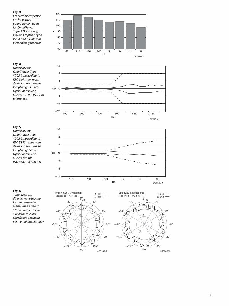
Fig. 3 Frequency response for 1/1-octave sound power levels for OmniPower Type 4292-L using Power Amplifier Type 2734 and its internal pink noise generator
Fig. 4 Directivity for OmniPower Type 4292-L according to ISO 140: maximum deviation from mean for ‘gliding’ 30arc. Upper and lower curves are the ISO 140 tolerances
Fig. 5 Directivity for OmniPower Type 4292-L according to ISO 3382: maximum deviation from mean for ‘gliding’ 30arc. Upper and lower curves are the ISO 3382 tolerances
Fig. 6 Type 4292-L’s directional response for the horizontal plane, measured in 1/3- octaves. Below 1 kHz there is no significant deviation from omnidirectionality
050190/1
60
70
80
90
100
110
120
63 125 250 500 1k 2k 4k 8kHz
dB
050191/1
–12
–8
–4
0
4
8
12
100 200 400 800 1.6k 3.15kHz
dB
050192/1
–12
–8
–4
0
4
8
12
125 250 500 1k 2k 4kHz
dB
–15
–5
5 dB0°
30°
60°
90°–90°
120°
150°180°
–150°
–120°
–60°
–30°
1 kHz2 kHz
Type 4292-L Directional Response – 1/3 oct.
050199/2
–15
–5
5 dB0°
30°
60°
90°–90°
120°
150°180°
–150°
–120°
–60°
–30°
4 kHz8 kHz
Type 4292-L Directional Response – 1/3 oct.
050200/2
3
OmniSource Sound Source Type 4295
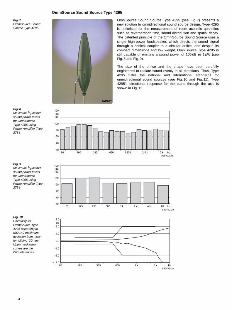
Fig. 7 OmniSource Sound Source Type 4295
OmniSource Sound Source Type 4295 (see Fig. 7) presents anew solution to omnidirectional sound source design. Type 4295is optimised for the measurement of room acoustic quantitiessuch as reverberation time, sound distribution and spatial decay.The patented principle of the OmniSource Sound Source uses asingle high-power loudspeaker, which directs the sound signalthrough a conical coupler to a circular orifice, and despite itscompact dimensions and low weight, OmniSource Type 4295 isstill capable of emitting a sound power of 105 dB re 1 pW (seeFig. 8 and Fig. 9).
The size of the orifice and the shape have been carefullyengineered to radiate sound evenly in all directions. Thus, Type4295 fulfils the national and international standards foromnidirectional sound sources (see Fig. 10 and Fig. 11). Type4295’s directional response for the plane through the axis isshown in Fig. 12.
Fig. 8 Maximum 1/3-octave sound power levels for OmniSource Type 4295 using Power Amplifier Type 2734
Fig. 9 Maximum 1/1-octave sound power levels for OmniSource Type 4295 using Power Amplifier Type 2734
Fig. 10 Directivity for OmniSource Type 4295 according to ISO 140 maximum deviation from mean for ‘gliding’ 30arc. Upper and lower curves are the ISO tolerances
120
110dB
80 5 k Hz2.5 k1.25 k630315160
100
90
80
70
60
980422/2e
120
110dB
63 125 Hz
100
90
80
70
60
980423/2e8 k4 k2 k1 k500250
12.0dB8.0
63 125 315 800 2 k 5 k Hz980415/2e
4.0
0.0
–4.0
–8.0
–12.0
4
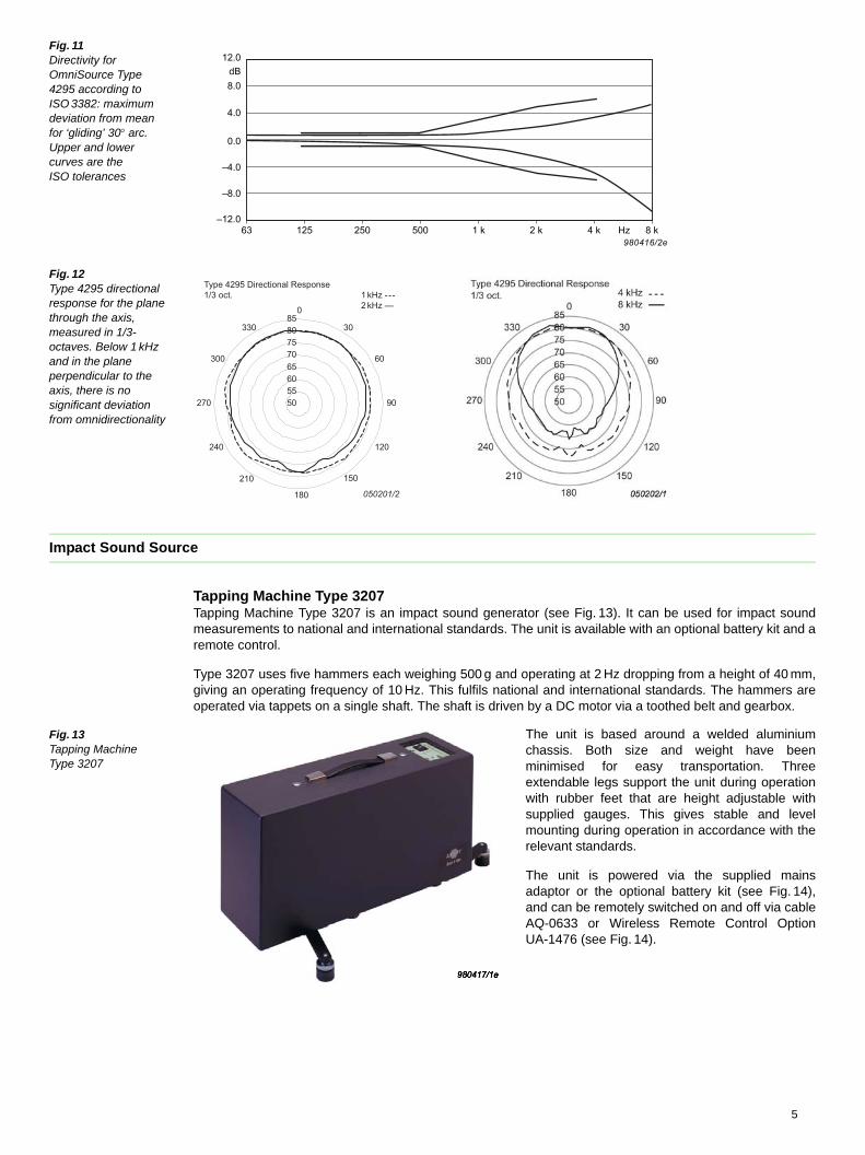
Fig. 11 Directivity for OmniSource Type 4295 according to ISO 3382: maximum deviation from mean for ‘gliding’ 30arc. Upper and lower curves are the ISO tolerances
Fig. 12 Type 4295 directional response for the plane through the axis, measured in 1/3- octaves. Below 1 kHz and in the plane perpendicular to the axis, there is no significant deviation from omnidirectionality
Impact Sound Source
Tapping Machine Type 3207Tapping Machine Type 3207 is an impact sound generator (see Fig. 13). It can be used for impact soundmeasurements to national and international standards. The unit is available with an optional battery kit and aremote control.
Type 3207 uses five hammers each weighing 500 g and operating at 2 Hz dropping from a height of 40 mm,giving an operating frequency of 10 Hz. This fulfils national and international standards. The hammers areoperated via tappets on a single shaft. The shaft is driven by a DC motor via a toothed belt and gearbox.
Fig. 13 Tapping Machine Type 3207
The unit is based around a welded aluminiumchassis. Both size and weight have beenminimised for easy transportation. Threeextendable legs support the unit during operationwith rubber feet that are height adjustable withsupplied gauges. This gives stable and levelmounting during operation in accordance with therelevant standards.
The unit is powered via the supplied mainsadaptor or the optional battery kit (see Fig. 14),and can be remotely switched on and off via cableAQ-0633 or Wireless Remote Control OptionUA-1476 (see Fig. 14).
12.0dB8.0
63 125 250 500 1 k 2 k Hz4 k 8 k
4.0
0.0
–4.0
–8.0
–12.0
980416/2e
5055606570758085
0
30
60
90
120
150
180
210
240
270
300
330
Type 4295 Directional Response1/3 oct. 1 kHz --- 2 kHz —
050201/2
5
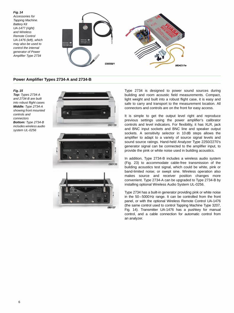
Fig. 14 Accessories for Tapping Machine. Battery Kit UA-1477 (right) and Wireless Remote Control UA-1476 (left), which may also be used to control the internal generator of Power Amplifier Type 2734
Power Amplifier Types 2734-A and 2734-B
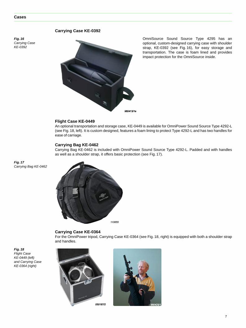
Fig. 15 Top: Types 2734-A and 2734-B are built into robust flight casesMiddle: Type 2734-A showing front mounted controls and connectorsBottom: Type 2734-B includes wireless audio system UL-0256
Type 2734 is designed to power sound sources duringbuilding and room acoustic field measurements. Compact,light weight and built into a robust flight case, it is easy andsafe to carry and transport to the measurement location. Allconnectors and controls are on the front for easy access.
It is simple to get the output level right and reproduceprevious settings using the power amplifier’s calibratorcontrols and level indicators. For flexibility, it has XLR, jackand BNC input sockets and BNC line and speaker outputsockets. A sensitivity selector in 10 dB steps allows theamplifier to adapt to a variety of source signal levels andsound source ratings. Hand-held Analyzer Type 2250/2270’sgenerator signal can be connected to the amplifier input, toprovide the pink or white noise used in building acoustics.
In addition, Type 2734-B includes a wireless audio system(Fig. 23) to accommodate cable-free transmission of thebuilding acoustics test signal, which could be white, pink orband-limited noise; or swept sine. Wireless operation alsomakes source and receiver position changes moreconvenient. Type 2734-A can be upgraded to Type 2734-B byinstalling optional Wireless Audio System UL-0256.
Type 2734 has a built-in generator providing pink or white noisein the 50–5000Hz range. It can be controlled from the frontpanel, or with the optional Wireless Remote Control UA-1476(the same control used to control Tapping Machine Type 3207,Fig. 14). Transmitter UA-1476 has a pushkey for manualcontrol, and a cable connection for automatic control froman analyzer.
6
Cases
Carrying Case KE-0392
Fig. 16 Carrying CaseKE-0392
OmniSource Sound Source Type 4295 has anoptional, custom-designed carrying case with shoulderstrap, KE-0392 (see Fig. 16), for easy storage andtransportation. The case is foam lined and providesimpact protection for the OmniSource inside.
Flight Case KE-0449 An optional transportation and storage case, KE-0449 is available for OmniPower Sound Source Type 4292-L(see Fig. 18, left). It is custom designed, features a foam lining to protect Type 4292-L and has two handles forease of carriage.
Carrying Bag KE-0462Carrying Bag KE-0462 is included with OmniPower Sound Source Type 4292-L. Padded and with handlesas well as a shoulder strap, it offers basic protection (see Fig. 17).
Fig. 17 Carrying Bag KE-0462
Carrying Case KE-0364For the OmniPower tripod, Carrying Case KE-0364 (see Fig. 18, right) is equipped with both a shoulder strapand handles.
Fig. 18 Flight Case KE-0449 (left) and Carrying Case KE-0364 (right)
7
Complete Systems
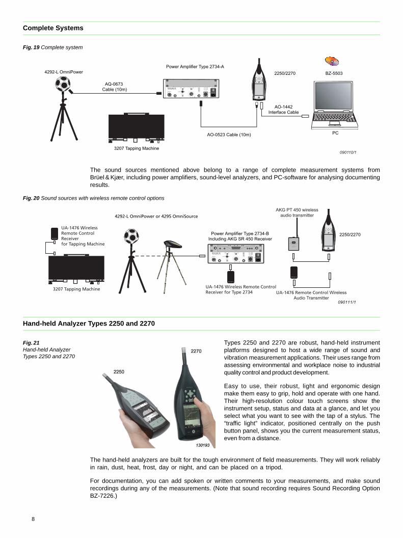
Fig. 19 Complete system
The sound sources mentioned above belong to a range of complete measurement systems fromBrüel & Kjær, including power amplifiers, sound-level analyzers, and PC-software for analysing documentingresults.
Fig. 20 Sound sources with wireless remote control options
Hand-held Analyzer Types 2250 and 2270
Fig. 21 Hand-held Analyzer Types 2250 and 2270
Types 2250 and 2270 are robust, hand-held instrumentplatforms designed to host a wide range of sound andvibration measurement applications. Their uses range fromassessing environmental and workplace noise to industrialquality control and product development.
Easy to use, their robust, light and ergonomic designmake them easy to grip, hold and operate with one hand.Their high-resolution colour touch screens show theinstrument setup, status and data at a glance, and let youselect what you want to see with the tap of a stylus. The“traffic light” indicator, positioned centrally on the pushbutton panel, shows you the current measurement status,even from a distance.
The hand-held analyzers are built for the tough environment of field measurements. They will work reliablyin rain, dust, heat, frost, day or night, and can be placed on a tripod.
For documentation, you can add spoken or written comments to your measurements, and make soundrecordings during any of the measurements. (Note that sound recording requires Sound Recording OptionBZ-7226.)
Power Amplifier Type 2734-A
3207 Tapping Machine
2250/2270
AO-0523 Cable (10m)
AO-1442Interface Cable
PC
BZ-5503 4292-L OmniPower
090110/1
AQ-0673 Cable (10m)
4292-L OmniPower or 4295 OmniSource
3207 Tapping Machine
UA-1476 WirelessRemote ControlReceiver for Tapping Machine
UA-1476 Wireless Remote ControlReceiver for Type 2734
090111/1
2250/2270
AKG PT 450 wirelessaudio transmitter
Power Amplifier Type 2734-BIncluding AKG SR 450 Receiver
UA-1476 Remote Control WirelessAudio Transmitter
8
Type 2250 is a single-channel analyzer, while Type 2270 is dual-channel and has additional features suchas a built-in camera allowing you to attach photos to your measurements and a LAN interface.
The high precision hand-held analyzers offer a wide range of optional software application modules,including prominent applications such as Reverberation Time Software and Building Acoustics Software.
Reverberation Time and Building Acoustics
Reverberation TimeReverberation time is an important feature of spaces where sound level, the intelligibility of speech, orperception of music is important. It is the time that it takes for a sound to decay by 60 dB. Usually, the timetaken for the signal to drop 20 or 30 dB is measured and extrapolated to find the time that it would take thesignal to dissipate by 60 dB.
Fig. 22 Reverberation Time measurement –measured using the interrupted noise method
Reverberation time is measured, using an impulse or aninterrupted noise, at several positions, which are thenaveraged together.
To measure reverberation time, simply press the Start/Pausepush button on the hand-held analyzer and, if you are usingimpulse excitation, burst the balloon.
A yellow ‘smiley’ icon indicates that you may be able to improvethe measurement at one (or more) frequency bands, a redsmiley indicates that the measurement should be retaken. Tapthe relevant smiley icon to read the explanation.
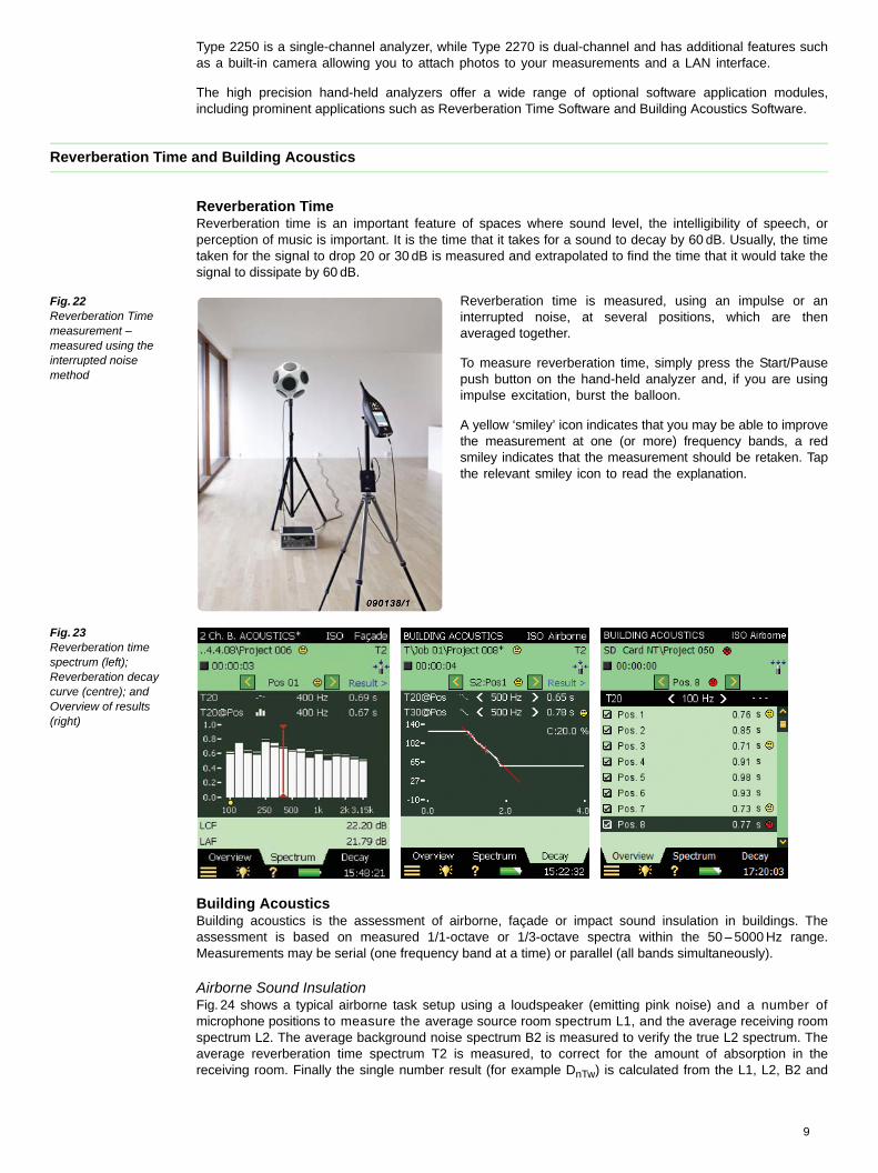
Fig. 23 Reverberation time spectrum (left); Reverberation decay curve (centre); andOverview of results (right)
Building AcousticsBuilding acoustics is the assessment of airborne, façade or impact sound insulation in buildings. Theassessment is based on measured 1/1-octave or 1/3-octave spectra within the 50 – 5000 Hz range.Measurements may be serial (one frequency band at a time) or parallel (all bands simultaneously).
Airborne Sound InsulationFig. 24 shows a typical airborne task setup using a loudspeaker (emitting pink noise) and a number ofmicrophone positions to measure the average source room spectrum L1, and the average receiving roomspectrum L2. The average background noise spectrum B2 is measured to verify the true L2 spectrum. Theaverage reverberation time spectrum T2 is measured, to correct for the amount of absorption in thereceiving room. Finally the single number result (for example DnTw) is calculated from the L1, L2, B2 and
9
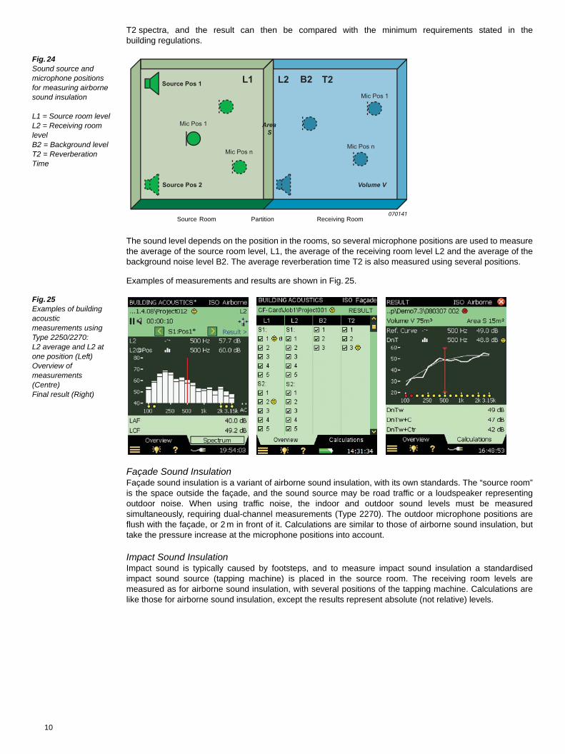
T2 spectra, and the result can then be compared with the minimum requirements stated in thebuilding regulations.
Fig. 24 Sound source and microphone positions for measuring airborne sound insulation
L1 = Source room levelL2 = Receiving room levelB2 = Background levelT2 = Reverberation Time
The sound level depends on the position in the rooms, so several microphone positions are used to measurethe average of the source room level, L1, the average of the receiving room level L2 and the average of thebackground noise level B2. The average reverberation time T2 is also measured using several positions.
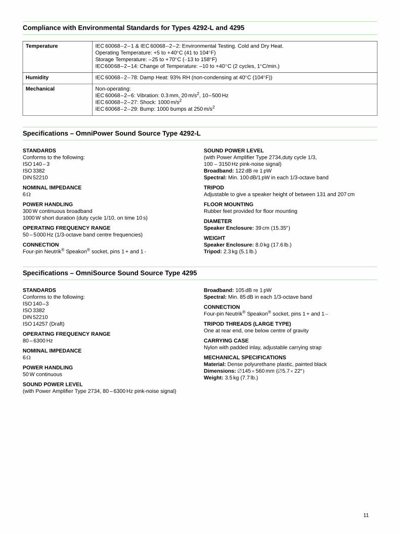
Examples of measurements and results are shown in Fig. 25.
Fig. 25 Examples of building acoustic measurements using Type 2250/2270:L2 average and L2 at one position (Left)Overview of measurements (Centre)Final result (Right)
Façade Sound InsulationFaçade sound insulation is a variant of airborne sound insulation, with its own standards. The “source room”is the space outside the façade, and the sound source may be road traffic or a loudspeaker representingoutdoor noise. When using traffic noise, the indoor and outdoor sound levels must be measuredsimultaneously, requiring dual-channel measurements (Type 2270). The outdoor microphone positions areflush with the façade, or 2 m in front of it. Calculations are similar to those of airborne sound insulation, buttake the pressure increase at the microphone positions into account.
Impact Sound InsulationImpact sound is typically caused by footsteps, and to measure impact sound insulation a standardisedimpact sound source (tapping machine) is placed in the source room. The receiving room levels aremeasured as for airborne sound insulation, with several positions of the tapping machine. Calculations arelike those for airborne sound insulation, except the results represent absolute (not relative) levels.
Source Pos 1
Source Pos 2 Volume V
Mic Pos 1
Mic Pos nMic Pos n
B2L1 L2 T2
Mic Pos 1
070141
Area S
Source Room Partition Receiving Room
10
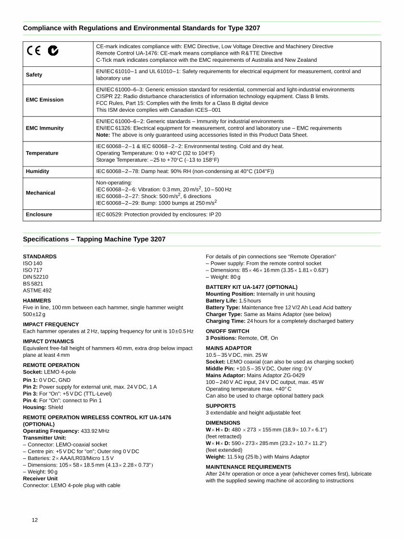
Compliance with Environmental Standards for Types 4292-L and 4295
Specifications – OmniPower Sound Source Type 4292-L
STANDARDSConforms to the following:ISO 140 – 3ISO 3382DIN 52210
NOMINAL IMPEDANCE6
POWER HANDLING300 W continuous broadband1000 W short duration (duty cycle 1/10, on time 10 s)
OPERATING FREQUENCY RANGE50 – 5000 Hz (1/3-octave band centre frequencies)
CONNECTIONFour-pin Neutrik® Speakon® socket, pins 1 + and 1 -
SOUND POWER LEVEL(with Power Amplifier Type 2734,duty cycle 1/3, 100 – 3150 Hz pink-noise signal)Broadband: 122 dB re 1 pWSpectral: Min. 100 dB/1 pW in each 1/3-octave band
TRIPODAdjustable to give a speaker height of between 131 and 207 cm
FLOOR MOUNTINGRubber feet provided for floor mounting
DIAMETERSpeaker Enclosure: 39 cm (15.35)
WEIGHTSpeaker Enclosure: 8.0 kg (17.6 lb.)Tripod: 2.3 kg (5.1 lb.)
Specifications – OmniSource Sound Source Type 4295
STANDARDSConforms to the following:ISO 140–3 ISO 3382 DIN 52210 ISO 14257 (Draft)
OPERATING FREQUENCY RANGE80 – 6300 Hz
NOMINAL IMPEDANCE6
POWER HANDLING50 W continuous
SOUND POWER LEVEL(with Power Amplifier Type 2734, 80 – 6300 Hz pink-noise signal)
Broadband: 105 dB re 1 pWSpectral: Min. 85 dB in each 1/3-octave band
CONNECTIONFour-pin Neutrik® Speakon® socket, pins 1 + and 1
TRIPOD THREADS (LARGE TYPE)One at rear end, one below centre of gravity
CARRYING CASENylon with padded inlay, adjustable carrying strap
MECHANICAL SPECIFICATIONSMaterial: Dense polyurethane plastic, painted blackDimensions: 145 560 mm (5.7 22Weight: 3.5 kg (7.7 lb.)
Temperature IEC 60068–2–1 & IEC 60068–2–2: Environmental Testing. Cold and Dry Heat.Operating Temperature: +5 to +40C (41 to 104F)Storage Temperature: –25 to +70C (13 to 158F)IEC60068–2–14: Change of Temperature: –10 to +40C (2 cycles, 1C/min.)
Humidity IEC 60068–2–78: Damp Heat: 93% RH (non-condensing at 40C (104F))
Mechanical Non-operating:IEC 60068–2–6: Vibration: 0.3 mm, 20 m/s2, 10–500 HzIEC 60068–2–27: Shock: 1000 m/s2
IEC 60068–2–29: Bump: 1000 bumps at 250 m/s2
11
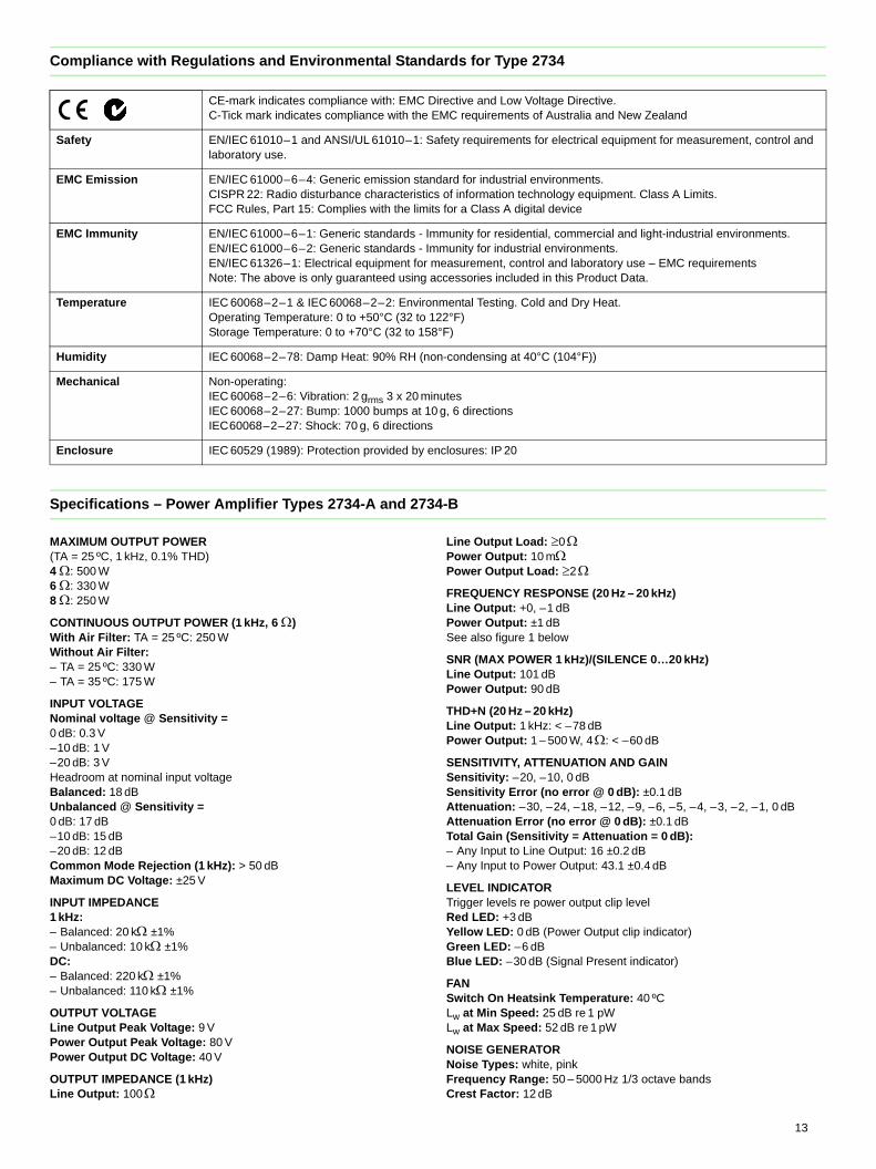
Compliance with Regulations and Environmental Standards for Type 3207
Specifications – Tapping Machine Type 3207
STANDARDSISO 140 ISO 717DIN 52210BS 5821ASTME 492
HAMMERSFive in line, 100 mm between each hammer, single hammer weight 500±12 g
IMPACT FREQUENCYEach hammer operates at 2 Hz, tapping frequency for unit is 10±0.5 Hz
IMPACT DYNAMICSEquivalent free-fall height of hammers 40 mm, extra drop below impact plane at least 4 mm
REMOTE OPERATIONSocket: LEMO 4-pole
Pin 1: 0 V DC, GNDPin 2: Power supply for external unit, max. 24 V DC, 1 APin 3: For “On”: +5 V DC (TTL-Level)Pin 4: For “On”: connect to Pin 1Housing: Shield
REMOTE OPERATION WIRELESS CONTROL KIT UA-1476 (OPTIONAL)Operating Frequency: 433.92 MHzTransmitter Unit:– Connector: LEMO-coaxial socket– Centre pin: +5 V DC for “on”; Outer ring 0 V DC– Batteries: 2 AAA/LR03/Micro 1.5 V– Dimensions: 105 58 18.5 mm (4.13 2.28 0.73– Weight: 90 gReceiver UnitConnector: LEMO 4-pole plug with cable
For details of pin connections see “Remote Operation”– Power supply: From the remote control socket– Dimensions: 85 46 16 mm (3.35 1.81 0.63)– Weight: 80 g
BATTERY KIT UA-1477 (OPTIONAL)Mounting Position: Internally in unit housingBattery Life: 1.5 hours Battery Type: Maintenance free 12 V/2 Ah Lead Acid batteryCharger Type: Same as Mains Adaptor (see below)Charging Time: 24 hours for a completely discharged battery
ON/OFF SWITCH 3 Positions: Remote, Off, On
MAINS ADAPTOR10.5 – 35 V DC, min. 25 WSocket: LEMO coaxial (can also be used as charging socket)Middle Pin: +10.5 – 35 V DC, Outer ring: 0 VMains Adaptor: Mains Adaptor ZG-0429100 – 240 V AC input, 24 V DC output, max. 45 WOperating temperature max. +40° CCan also be used to charge optional battery pack
SUPPORTS3 extendable and height adjustable feet
DIMENSIONSW H D: 480 273 155 mm (18.9 10.7 6.1)(feet retracted)W H D: 590 273 285 mm (23.2 10.7 11.2)(feet extended)Weight: 11.5 kg (25 lb.) with Mains Adaptor
MAINTENANCE REQUIREMENTSAfter 24 hr operation or once a year (whichever comes first), lubricate with the supplied sewing machine oil according to instructions
CE-mark indicates compliance with: EMC Directive, Low Voltage Directive and Machinery DirectiveRemote Control UA-1476: CE-mark means compliance with R&TTE DirectiveC-Tick mark indicates compliance with the EMC requirements of Australia and New Zealand
SafetyEN/IEC 61010–1 and UL 61010–1: Safety requirements for electrical equipment for measurement, control and laboratory use
EMC Emission
EN/IEC 61000–6–3: Generic emission standard for residential, commercial and light-industrial environmentsCISPR 22: Radio disturbance characteristics of information technology equipment. Class B limits. FCC Rules, Part 15: Complies with the limits for a Class B digital deviceThis ISM device complies with Canadian ICES–001
EMC ImmunityEN/IEC 61000–6–2: Generic standards – Immunity for industrial environmentsEN/IEC 61326: Electrical equipment for measurement, control and laboratory use – EMC requirementsNote: The above is only guaranteed using accessories listed in this Product Data Sheet.
TemperatureIEC 60068–2–1 & IEC 60068–2–2: Environmental testing. Cold and dry heat.Operating Temperature: 0 to +40C (32 to 104F)Storage Temperature: –25 to +70C (13 to 158F)
Humidity IEC 60068–2–78: Damp heat: 90% RH (non-condensing at 40°C (104°F))
Mechanical
Non-operating:IEC 60068–2–6: Vibration: 0.3 mm, 20 m/s2, 10 – 500 HzIEC 60068–2–27: Shock: 500 m/s2, 6 directionsIEC 60068–2–29: Bump: 1000 bumps at 250 m/s2
Enclosure IEC 60529: Protection provided by enclosures: IP 20
12
Compliance with Regulations and Environmental Standards for Type 2734
Specifications – Power Amplifier Types 2734-A and 2734-B
MAXIMUM OUTPUT POWER(TA = 25 ºC, 1 kHz, 0.1% THD)4 : 500 W6 : 330 W8 : 250 W
CONTINUOUS OUTPUT POWER (1 kHz, 6 )With Air Filter: TA = 25 ºC: 250 WWithout Air Filter: – TA = 25 ºC: 330 W– TA = 35 ºC: 175 W
INPUT VOLTAGENominal voltage @ Sensitivity = 0 dB: 0.3 V–10 dB: 1 V–20 dB: 3 VHeadroom at nominal input voltageBalanced: 18 dBUnbalanced @ Sensitivity = 0 dB: 17 dB–10 dB: 15 dB–20 dB: 12 dBCommon Mode Rejection (1 kHz): > 50 dB Maximum DC Voltage: ±25 V
INPUT IMPEDANCE1 kHz: – Balanced: 20 k ±1% – Unbalanced: 10 k ±1% DC: – Balanced: 220 k ±1% – Unbalanced: 110 k ±1%
OUTPUT VOLTAGELine Output Peak Voltage: 9 VPower Output Peak Voltage: 80 V Power Output DC Voltage: 40 V
OUTPUT IMPEDANCE (1 kHz)Line Output: 100
Line Output Load: 0Power Output: 10 mPower Output Load: 2
FREQUENCY RESPONSE (20 Hz – 20 kHz)Line Output: +0, –1 dBPower Output: ±1 dBSee also figure 1 below
SNR (MAX POWER 1 kHz)/(SILENCE 0…20 kHz)Line Output: 101 dBPower Output: 90 dB
THD+N (20 Hz – 20 kHz)Line Output: 1 kHz: < –78 dBPower Output: 1 – 500 W, 4: < –60 dB
SENSITIVITY, ATTENUATION AND GAINSensitivity: –20, –10, 0 dBSensitivity Error (no error @ 0 dB): ±0.1 dBAttenuation: –30, –24, –18, –12, –9, –6, –5, –4, –3, –2, –1, 0 dBAttenuation Error (no error @ 0 dB): ±0.1 dBTotal Gain (Sensitivity = Attenuation = 0 dB): – Any Input to Line Output: 16 ±0.2 dB– Any Input to Power Output: 43.1 ±0.4 dB
LEVEL INDICATORTrigger levels re power output clip levelRed LED: +3 dBYellow LED: 0 dB (Power Output clip indicator)Green LED: –6 dBBlue LED: –30 dB (Signal Present indicator)
FANSwitch On Heatsink Temperature: 40 ºCLw at Min Speed: 25 dB re 1 pWLw at Max Speed: 52 dB re 1 pW
NOISE GENERATORNoise Types: white, pinkFrequency Range: 50 – 5000 Hz 1/3 octave bandsCrest Factor: 12 dB
CE-mark indicates compliance with: EMC Directive and Low Voltage Directive.C-Tick mark indicates compliance with the EMC requirements of Australia and New Zealand
Safety EN/IEC 61010–1 and ANSI/UL 61010–1: Safety requirements for electrical equipment for measurement, control and laboratory use.
EMC Emission EN/IEC 61000–6–4: Generic emission standard for industrial environments.CISPR 22: Radio disturbance characteristics of information technology equipment. Class A Limits.FCC Rules, Part 15: Complies with the limits for a Class A digital device
EMC Immunity EN/IEC 61000–6–1: Generic standards - Immunity for residential, commercial and light-industrial environments.EN/IEC 61000–6–2: Generic standards - Immunity for industrial environments.EN/IEC 61326–1: Electrical equipment for measurement, control and laboratory use – EMC requirementsNote: The above is only guaranteed using accessories included in this Product Data.
Temperature IEC 60068–2–1 & IEC 60068–2–2: Environmental Testing. Cold and Dry Heat.Operating Temperature: 0 to +50°C (32 to 122°F)Storage Temperature: 0 to +70°C (32 to 158°F)
Humidity IEC 60068–2–78: Damp Heat: 90% RH (non-condensing at 40°C (104°F))
Mechanical Non-operating: IEC 60068–2–6: Vibration: 2 grms 3 x 20 minutesIEC 60068–2–27: Bump: 1000 bumps at 10 g, 6 directionsIEC60068–2–27: Shock: 70 g, 6 directions
Enclosure IEC 60529 (1989): Protection provided by enclosures: IP 20
13
Period Time: 22.5 sThird Octave Spectral Error: ±0.3 dBLine Output Voltage (Sensitivity = Attenuation = 0 dB): 2.16 VrmsSwitch Off: Equivalent RT in 1/3 octaves: <50 ms @ 50 Hz, <4 ms @ 5 kHz
CONNECTORSBalanced Input Socket: Neutrik® Combo XLR-type: 3-pin and ¼” jackUnbalanced Input Socket: BNCUnbalanced Line Output Socket: BNCPower (Speaker) Output Socket: Neutrik® 4-pole Speakon® typeMains Power Inlet: IEC type
CONTROLSGenerator Button: Toggling between On and OffGenerator Slide Switch: 2-state, White/Pink noise Sensitivity slide switch: 3-state, –20, –10, 0 dB Attenuation Rotary Knob: 12-state, –30, –24, –18, –12, –9, –6, –5, –4, –3, –2, –1, 0 dBMains Power Rocker Switch: 2-pole
STATUS INDICATORSProtect Indicator: Red LED, power output over-current, overheat, overload or long-term high frequencyPower On Indicator: Green LED
MAINS POWERVoltage Selector (Rear Panel): 230/115 VMains Voltage Range: – @ 230 V: 200 - 240 V– @ 115 V: 100 - 125 VMains Frequency Range: 45 – 65 HzFuse: Wickmann/Littlefuse series 215 (or 181)– @ 230 V: T 3.15 AH 250 V– @ 115 V: T 6.3 AH 125 V
Maximum Power Consumption: 650 W
MECHANICALWeight (including mains cord in lid): – Type 2734-A: 6.0 kg– Type 2734-B: 7.0 kgDimensions W H D: 330 130 310 mm (13 5.1 12 “)
TRANSMITTER AKG PT 450 (OPTIONAL)Specifications from manufacturer's technical dataRF Carrier Frequency Ranges: 7 channels over 650 – 865 MHzModulation: FMAudio Bandwidth: 35 to 20000 HzTHD (typical at rated deviation/1 kHz): <0.7% S/N Ratio: 120 dB(A)RF Output: 50 mW max. (ERP)Battery Life: 1.5 V AA Dry Battery: 6 hours; 1.2 V NiMH, 2100 mAh AA sizeRechargeable Battery: 8 hrs– Size: 60 73.5 30 mm (2.4 2.9 1.2")– Net weight: 90 g (3.2 oz.)
RECEIVER AKG SR 450 (OPTIONAL)Specifications from manufacturer's technical dataRF Carrier Frequency Ranges: 7 channels over 650 – 865 MHzModulation: FMAudio Bandwidth: 35 to 20000 HzTHD at 1 kHz: <0.3%S/N Ratio: 120 dB(A)Audio Outputs: Balanced XLR and unbalanced TS 1/4" jack, balanced level switchable to –30 or 0 dBm
MECHANICALDimensions: 200 44 190 mm (7.8 1.7 7.4")Weight: 972 g (2.2 lbs)
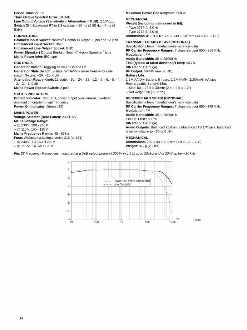
Fig. 27 Frequency Responses measured at a 0 dB output power of 300 W into 6 up to 20 kHz and of 20 W up from 20 kHz
-12
-10
-8
-6
-4
-2
0
2
10 100 1k 10k 100k120411Hz
Power Out into 6 Ohms [dB]Line Out [dB]
14
15
Ordering Information
Type 4292-L OmniPower Sound SourceType 4295 OmniSource Sound SourceType 3207 Tapping Machine
Included Accessories
ACCESSORIES INCLUDED WITH TYPE 4292-L• KE-0462 Carrying Bag for Type 4292-L• UA-1690 Tripod
ACCESSORIES INCLUDED WITH TYPE 3207• ZG-0429 Mains adaptor (mains cable country dependent)• 2 Gauges for drop height adjustment• Oil canister for maintenance
OPTIONAL ACCESSORIESType 2734-A Power AmplifierType 2734-B Power Amplifier with built-in UL-0256 Wireless Audio
SystemUL-0256 Wireless Audio SystemKE-0392 Carrying Case for Type 4295KE-0449 Flight Case for Type 4292-LKE-0364 Carrying Case for Type 4292 Tripod (UA-1690)UA-0801 Lightweight TripodAO-0523 Signal cable from Hand-held analyzer to Power
Amplifier, 10 m (32.8 ft)AO-0524 Signal cable from Hand-held Analyzer to BNC, 10 m
(32.8 ft)AQ-0673 Speaker cable from Type 2734 to Types 4292, 4295
or equivalent, 10 m (32.8 ft)Type 2250-F Hand-held Analyzer Type 2250 with Sound Level
Meter Software BZ-7222 and Reverberation Time Software BZ-7227
Type 2270-F Hand-held Analyzer Type 2270 with Sound Level Meter Software BZ-7222 and Reverberation Time Software BZ-7227
Type 2250-J Hand-held Analyzer Type 2250 with Sound Level Meter Software BZ-7222 and Building Acoustics Software BZ-7228
Type 2270-J Hand-held Analyzer Type 2270 with Sound Level Meter Software BZ-7222 and Building Acoustics Software BZ-7228
Type 2270-K Hand-held Analyzer Type 2270 with Sound Level Meter Software BZ-7222 and Dual-channel Building Acoustics Software BZ-7229
Type 2250-J-001 Building Acoustics System including Type 2250-J, OmniPower Sound Source Type 4292 and Power Amplifier Type 2734-A
Type 2270-J-001 Building Acoustics System including Type 2270-J, OmniPower Sound Source Type 4292 and Power Amplifier Type 2734-A
Type 2270-K-001 Dual-channel Building Acoustics System including Type 2270-K, OmniPower Sound Source Type 4292 and Power Amplifier Type 2734-A
BZ-7228-200 Building Acoustics Kit as per Type 2250-J-001, or Type 2270-J-001, excluding Hand-held Analyzer (for Types 2250 and 2270 users intending to upgrade to a full Building Acoustics measurement system)
BZ-7229-200 Dual-channel Building Acoustics Kit as per Type 2270-K-001, excluding Type 2270 (for Type 2270 users intending to upgrade to a full Dual-channel Building Acoustics measurement system)
Type 8780 PULSE Reflex Building Acoustics SoftwareType 7830 Qualifier PC Software for Building Acoustics reportingType 7831 Qualifier Light PC Software for reverberation time
reporting
Go to www.bksv.com for more information on Types 2250 and 2270 and Brüel & Kjær’s Buidling Acoustics applications.
OPTIONAL ACCESSORIES FOR TYPE 3207AQ-0633 Remote Cable connecting Type 2260 Investigator to
Type 3207, 10 m (32.8 ft)UA-1476 Wireless Remote Control (includes AO-1439 Cable
for Hand-held Analzyer Types 2250 and 2270)UA-1477 Battery KitQB-0055 Replacement battery

HEADQUARTERS: Brüel & Kjær Sound & Vibration Measurement A/S · DK-2850 Nærum · DenmarkTelephone: +45 7741 2000 · Fax: +45 4580 1405 · www.bksv.com · [email protected]
Local representatives and service organisations worldwide
ËBP-1689---zÎ
BP
1689
–24
201
3-05
Brüel & Kjær reserves the right to change specifications and accessories without notice. © Brüel & Kjær. All rights reserved.