Embed Size (px)
Citation preview
Product Data Sheet 00813-0100-4697
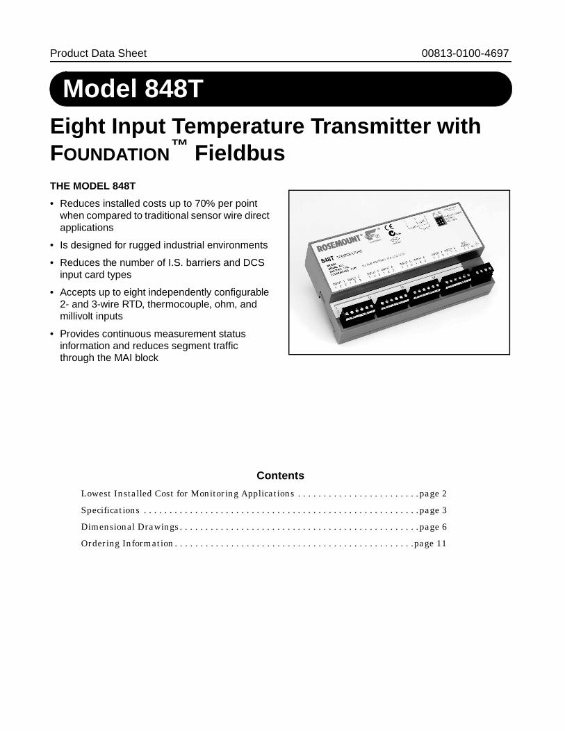
Model 848TEight Input Temperature Transmitter withFOUNDATION™ FieldbusTHE MODEL 848T
• Reduces installed costs up to 70% per pointwhen compared to traditional sensor wire directapplications
• Is designed for rugged industrial environments
• Reduces the number of I.S. barriers and DCSinput card types
• Accepts up to eight independently configurable2- and 3-wire RTD, thermocouple, ohm, andmillivolt inputs
• Provides continuous measurement statusinformation and reduces segment trafficthrough the MAI block
Contents
Lowest Installed Cost for Monitoring Applications . . . . . . . . . . . . . . . . . . . . . . . .page 2
Specifications . . . . . . . . . . . . . . . . . . . . . . . . . . . . . . . . . . . . . . . . . . . . . . . . . . . . . .page 3
Dimensional Drawings. . . . . . . . . . . . . . . . . . . . . . . . . . . . . . . . . . . . . . . . . . . . . . .page 6
Ordering Information. . . . . . . . . . . . . . . . . . . . . . . . . . . . . . . . . . . . . . . . . . . . . . .page 11
2 www.rosemount.comwww.rosemount.com
Lowest Installed Cost for Monitoring Applications
The Model 848T Eight Input Temperature Transmitter will simplify and reduce the cost of a plant’s processcontrol architecture. Traditional temperature monitoring methods (wire direct and multiplexers) will beeliminated with the introduction of this intrinsically safe, eight input transmitter that mounts beside theprocess. The use of FOUNDATION fieldbus enables this quantum leap in temperature monitoring.
LOWEST COST SOLUTION
The Model 848T offers the lowest cost solution fortemperature monitoring measurements. (e.g.distillation columns, tanks, reactors, boilers, etc.).This transmitter can reduce installed costs by asmuch as 70% per point when compared totraditional sensor wire direct applications.
REDUCES I.S. BARRIER COSTS
For intrinsically safe installations, only one barrieris needed to safely power several Model 848Ttransmitters. As a result, one barrier can support atleast 24 temperature measurement points–resulting in significant savings.
EIGHT INDEPENDENT SENSOR INPUTS
The Model 848T accepts eight independentlyconfigurable sensor inputs (2- and 3-wire RTDs,thermocouples, mV, and ohm).
MOUNTS VIRTUALLY ANYWHERE
The Model 848T’s ambient temperature limits, RFIimmunity compliance, intrinsic safety approvals,and ability to mount in industrial environmentsprovides optimum mounting flexibility.
DIAGNOSTICS AND MAI FUNCTIONBLOCKS
FOUNDATION fieldbus offers inherent diagnosticsthat provide continuous measurement status (good,bad, or uncertain) as well as sensor failureindication. Also, the Model 848T offers theMultiplexed Analog Input (MAI) function block. TheMAI block allows all eight sensor inputs to bebrought directly into one function block, reducingmessage traffic on the fieldbus network.
Rosemount Temperature Solutions
Model 3144 and 3244MV Temperature TransmittersField mount style available in HART,FOUNDATION fieldbus, and Profibus-PA protocols.
Model 644 Smart Temperature TransmitterHead or rail mount styles available with HARTprotocol
Model 848T Eight Input Temperature TransmitterEight input transmitter available withFOUNDATION fieldbus protocol.
Model 244E Temperature TransmittersHead or rail mount styles that arePC-programmable.
Model 144H Temperature TransmittersHead mount style for 2- and 3-wire RTD sensorinputs. PC-programmable.
Rosemount sensors, thermowells, and extensionsRosemount has a broad offering of RTD andthermocouple solutions designed meet any plantrequirement.
Rosemount Inc.
3www.rosemount.comwww.rosemount.com
Specifications
FUNCTIONAL
InputsEight independently configurable channelsincluding combinations of 2- and 3-wireRTDs, thermocouples, mV, and inputs.Sensor terminals are rated to 42.4 VDC.
OutputsManchester-encoded digital signal thatconforms to IEC 1158-2 and ISA 50.02.
StatusIf self-diagnostics detect a sensor burnoutor a transmitter failure, the status of themeasurement will be updated accordingly.
Ambient Temperature Limits–40 to 185 °F (–40 to 85 °C)
IsolationInput/output isolation tested to 500 VAC rms(707 VDC). Isolation between sensor pairsis tested to 500 VAC rms (707 VDC).Rosemount Inc. does not recommend theuse of two independently groundedthermocouples within a sensor pair.
Power SupplyPowered over FOUNDATION fieldbus withstandard fieldbus power supplies. Thetransmitter operates between 9.0 and32.0 V dc, 22 mA maximum. (Transmitterpower terminals are rated to 42.4 V dc.)
Transient ProtectionThe transient protector (option code T1)helps to prevent damage to the transmitterfrom transients induced on the loop wiringby lightening, welding, heavy electricalequipment, or switch gears. This option isinstalled at the factory for the Model 848Tand is not intended for field installation.
ASME B 16.5 (ANSI)/IEEE C62.41-1991
(IEEE 587), Location Categories A2, B3.
1 kV peak (10 x 1000 S Wave)
6 kV / 3 kA peak (1.2 x 50 S Wave 8 x 20mS Combination Wave)
6 kV / 0.5 kA peak (100 kHz Ring Wave)
4 kV peak EFT (5 x 50 nS ElectricalFast Transient)
Update TimeApproximately 1.5 seconds to read alleight sensors
Humidity Limits0–100% non-condensing relative humidity
AlarmsThe AI and ISEL blocks allow the user toconfigure the alarms to HI-HI, HI, LO, orLO-LO with a variety of priority levels andhysteresis settings.
Turn-on TimePerformance within specifications isachieved less than 50.0 seconds afterpower is applied to the transmitter.
FOUNDATION Fieldbus
Backup Link Active Scheduler (LAS)The transmitter is classified as a device linkmaster, which means it can function as aLink Active Scheduler (LAS) if the currentlink master device fails or is removed fromthe segment.
The host or other configuration tool is usedto download the schedule for the applicationto the link master device. In the absence ofa primary link master, the transmitter willclaim the LAS and provide permanentcontrol for the H1 segment.
PHYSICAL
Entries for Optional Junction BoxNo entry
• Used for custom fittings
Cable Gland• 9 x M20 glands for 8-13 mm
unarmored cable
Conduit• 5 plugged 0.86-in. diameter holes
suitable for installing 1/2-in. NPT fittings.
Materials of Construction forOptional Junction Box
Weight
MountingThe Model 848T can be mounted directlyonto a DIN rail or it can be ordered with anoptional junction box. When using theoptional junction box, the transmitter can bemounted onto a panel or to a 2-in. pipestand (with option code B6).
Environmental RatingsNEMA 4X, CSA Enclosure Type 4X,and IP66 with optional junction box.
FUNCTION BLOCKSAnalog Input (AI)
• Processes the measurementand makes it available on thefieldbus segment.
• Allows filtering, alarming, andengineering unit changes.
Input Selector (ISEL)• Used to select between inputs and
generate an output using specificselection strategies such as minimum,maximum, midpoint, or averagetemperature.
• Since the temperature value alwayscontains the measurement status, thisblock allows the selection to berestricted to the first “good”measurement.
Multiplexer AI Block (MAI)• The MAI block allows the eight AI
blocks to be multiplexed together sothey serve as one function block on theH1 segment, resulting in reducedmessage traffic.
Instantiable Function Blocks• All the function blocks used by the
transmitter are instantiable, meaningthat there is no specified limit to thenumber of function blocks that can be inuse at any given time.
• The only limitation to the number ofblocks in use is the amount of physicalmemory available to the transmitter. Asa result, the function blocks can beconfigured so that only necessaryblocks use transmitter memory.
Schedule Entries 25Links 30Virtual CommunicationsRelationships (VCR)
20
Junction Box Type Paint
Aluminum (1)
(1) Plastic cable glands
PolyurethanePlastic(1) NAStainless Steel (2)
(2) Nickel-plated brass cable glands
NA
Assembly Weight
oz lb kg
Model 848T only 9.60 0.60 0.27Aluminum 78.2 4.89 2.22Plastic 58.1 3.68 1.65Stainless Steel (1)
(1) Add 11.0 oz (0.688 lb, 0.312 kg) forbrass glands
77.0 4.81 2.18
Rosemount Model 848T Eight Input Temperature Transmitter with FOUNDATION Fieldbus
4 www.rosemount.comwww.rosemount.com
PERFORMANCEThe transmitter maintains a specificationconformance of at least 3� .
Stability• ±0.1% of reading or 0.1 °C (0.18 °F),
whichever is greater, for 2 yearsfor RTDs.
• ±0.1% of reading or 0.1 °C (0.18 °F),whichever is greater, for 1 year forthermocouples.
Self CalibrationThe transmitter’s analog-to-digital circuitryautomatically self-calibrates for eachtemperature update by comparing thedynamic measurement to extremely stableand accurate internal reference elements.
Vibration EffectTransmitters tested to the following with noeffect on performance:
CE Electromagnetic CompatibilityCompliance TestingMeets the criteria under IEC 61326Amendment 1, 2000:
AccuracyRefer to Table 1
Accuracy NotesDifferential capability exists between anytwo sensor types:
For all differential configurations, the inputrange is X to +Y where
Accuracy for differential configurations:If sensor types are similar (for example,both RTDs or both thermocouples),the accuracy = 1.5 times worst caseaccuracy of either sensor type. If sensortypes are dissimilar (for example, one RTDand one thermocouple), the accuracy= Sensor 1 Accuracy + Sensor 2 Accuracy.
Using Grounded Thermocouples inmonitoring and differential temperatureapplications:Independently-grounded thermocouplescould create ground loops and could resultin measurement errors. Rosemount Inc.does not recommend the use of twoindependently grounded thermocoupleswithin a sensor pair.
Frequency Acceleration
10 - 60 Hz 0.21 mm peak displacement60 - 2000 Hz 3 g
Emissions
• 30–230 MHz, 30 dB (uV/m) at 10 m
• 230–1000 MHz, 37 dB (uV/m) at 10 m
Susceptibility
• ESD • 4 kV contact discharge• 8 kV air discharge
• Radiated • 80 – 1000 MHz at10 V/m AM
• Burst • 1 kV
• Surge • 1 kV line–to-ground
• Conducted • 150 kHz to 80 MHzat 3V
• Magnetic • 50 Hz at 30 A/m
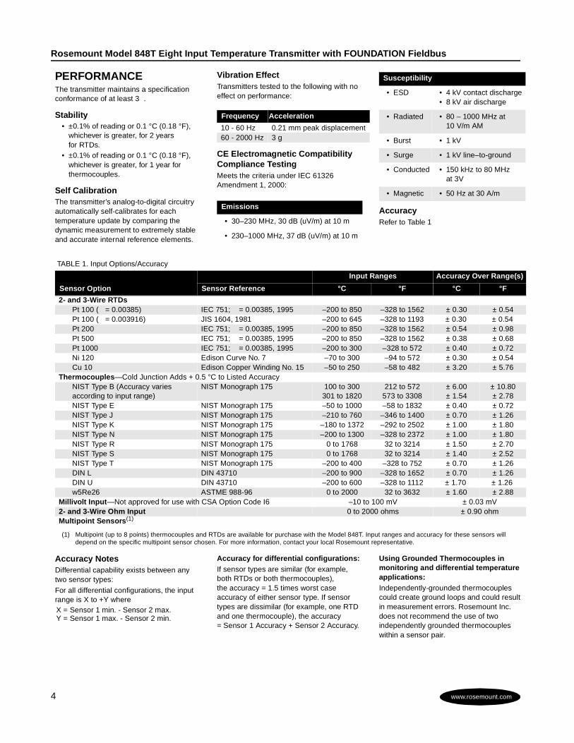
TABLE 1. Input Options/Accuracy
Sensor Option
Input Ranges Accuracy Over Range(s)
Sensor Reference °C °F °C °F
2- and 3-Wire RTDsPt 100 ( � = 0.00385) IEC 751; � = 0.00385, 1995 –200 to 850 –328 to 1562 ± 0.30 ± 0.54Pt 100 ( � = 0.003916) JIS 1604, 1981 –200 to 645 –328 to 1193 ± 0.30 ± 0.54Pt 200 IEC 751; � = 0.00385, 1995 –200 to 850 –328 to 1562 ± 0.54 ± 0.98Pt 500 IEC 751; � = 0.00385, 1995 –200 to 850 –328 to 1562 ± 0.38 ± 0.68Pt 1000 IEC 751; � = 0.00385, 1995 –200 to 300 –328 to 572 ± 0.40 ± 0.72Ni 120 Edison Curve No. 7 –70 to 300 –94 to 572 ± 0.30 ± 0.54Cu 10 Edison Copper Winding No. 15 –50 to 250 –58 to 482 ± 3.20 ± 5.76
Thermocouples—Cold Junction Adds + 0.5 °C to Listed AccuracyNIST Type B (Accuracy variesaccording to input range)
NIST Monograph 175 100 to 300301 to 1820
212 to 572573 to 3308
± 6.00± 1.54
± 10.80± 2.78
NIST Type E NIST Monograph 175 –50 to 1000 –58 to 1832 ± 0.40 ± 0.72NIST Type J NIST Monograph 175 –210 to 760 –346 to 1400 ± 0.70 ± 1.26NIST Type K NIST Monograph 175 –180 to 1372 –292 to 2502 ± 1.00 ± 1.80NIST Type N NIST Monograph 175 –200 to 1300 –328 to 2372 ± 1.00 ± 1.80NIST Type R NIST Monograph 175 0 to 1768 32 to 3214 ± 1.50 ± 2.70NIST Type S NIST Monograph 175 0 to 1768 32 to 3214 ± 1.40 ± 2.52NIST Type T NIST Monograph 175 –200 to 400 –328 to 752 ± 0.70 ± 1.26DIN L DIN 43710 –200 to 900 –328 to 1652 ± 0.70 ± 1.26DIN U DIN 43710 –200 to 600 –328 to 1112 ± 1.70 ± 1.26w5Re26 ASTME 988-96 0 to 2000 32 to 3632 ± 1.60 ± 2.88
Millivolt Input—Not approved for use with CSA Option Code I6 –10 to 100 mV ± 0.03 mV2- and 3-Wire Ohm Input 0 to 2000 ohms ± 0.90 ohmMultipoint Sensors(1)
(1) Multipoint (up to 8 points) thermocouples and RTDs are available for purchase with the Model 848T. Input ranges and accuracy for these sensors willdepend on the specific multipoint sensor chosen. For more information, contact your local Rosemount representative.
X = Sensor 1 min. - Sensor 2 max.Y = Sensor 1 max. - Sensor 2 min.
Rosemount Inc.
5www.rosemount.comwww.rosemount.com
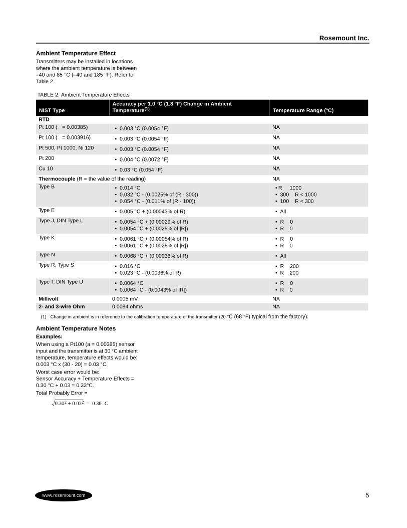
Ambient Temperature EffectTransmitters may be installed in locationswhere the ambient temperature is between–40 and 85 °C (–40 and 185 °F). Refer toTable 2.
Ambient Temperature NotesExamples:When using a Pt100 (a = 0.00385) sensorinput and the transmitter is at 30 °C ambienttemperature, temperature effects would be:0.003 °C x (30 - 20) = 0.03 °C.
Worst case error would be:Sensor Accuracy + Temperature Effects =0.30 °C + 0.03 = 0.33°C.
Total Probably Error =
TABLE 2. Ambient Temperature Effects
NIST TypeAccuracy per 1.0 °C (1.8 °F) Change in AmbientTemperature(1)C Temperature Range (°C)
RTDPt 100 ( = 0.00385) • 0.003 °C (0.0054 °F) NA
Pt 100 ( = 0.003916) • 0.003 °C (0.0054 °F) NA
Pt 500, Pt 1000, Ni 120 • 0.003 °C (0.0054 °F) NA
Pt 200 • 0.004 °C (0.0072 °F) NA
Cu 10 • 0.03 °C (0.054 °F) NA
Thermocouple (R = the value of the reading) NA
Type B • 0.014 °C• 0.032 °C - (0.0025% of (R - 300))• 0.054 °C - (0.011% of (R - 100))
• R 1000• 300 R < 1000• 100 R < 300
Type E • 0.005 °C + (0.00043% of R) • All
Type J, DIN Type L • 0.0054 °C + (0.00029% of R)• 0.0054 °C + (0.0025% of |R|)
• R 0• R 0
Type K • 0.0061 °C + (0.00054% of R)• 0.0061 °C + (0.0025% of |R|)
• R 0• R 0
Type N • 0.0068 °C + (0.00036% of R) • All
Type R, Type S • 0.016 °C• 0.023 °C - (0.0036% of R)
• R 200• R 200
Type T, DIN Type U • 0.0064 °C• 0.0064 °C - (0.0043% of |R|)
• R 0• R 0
Millivolt 0.0005 mV NA
2- and 3-wire Ohm 0.0084 ohms NA
(1) Change in ambient is in reference to the calibration temperature of the transmitter (20 °C (68 °F) typical from the factory).
0.302 0.032+ 0.30 C=
Rosemount Model 848T Eight Input Temperature Transmitter with FOUNDATION Fieldbus
6 www.rosemount.comwww.rosemount.com
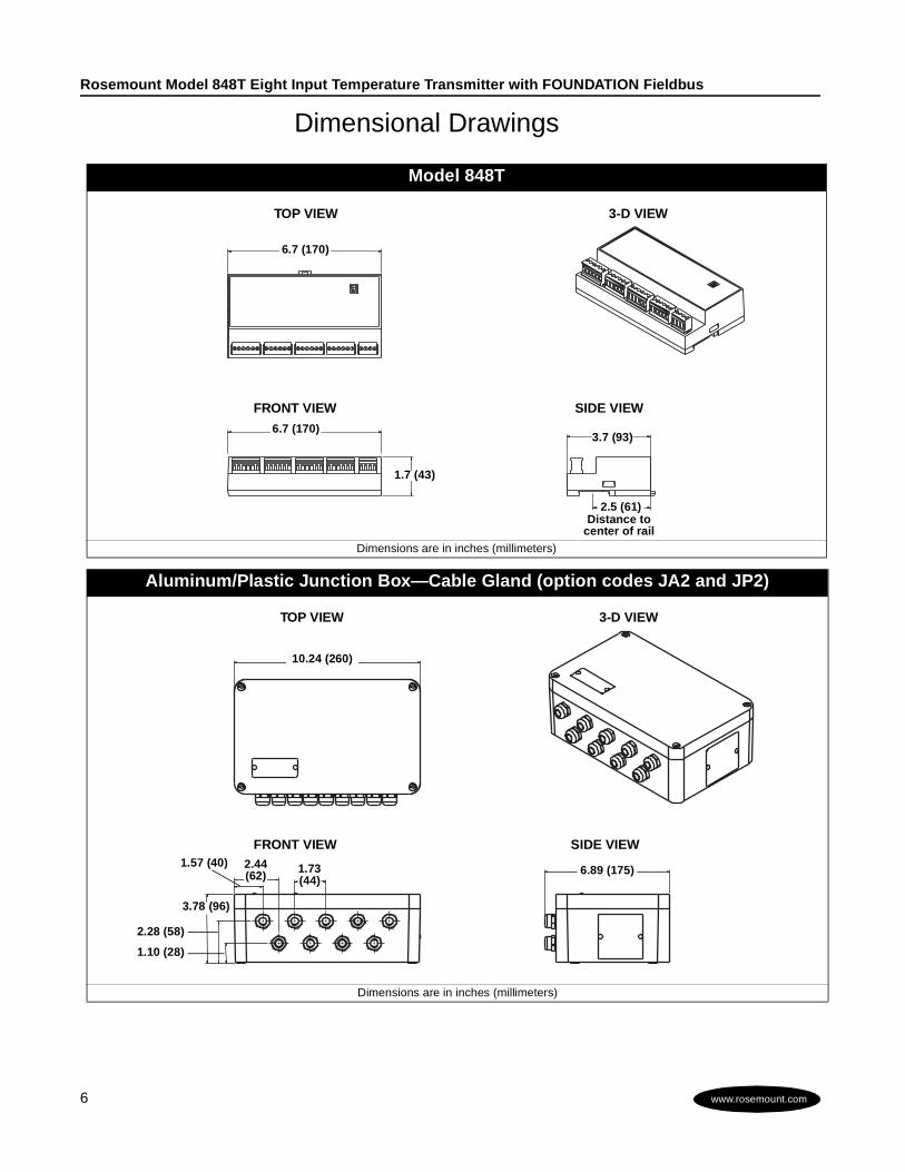
Dimensional Drawings
Model 848T
Dimensions are in inches (millimeters)
Aluminum/Plastic Junction Box—Cable Gland (option codes JA2 and JP2)
Dimensions are in inches (millimeters)
1.7 (43)
3.7 (93)
6.7 (170)
6.7 (170)
TOP VIEW
FRONT VIEW SIDE VIEW
3-D VIEW
2.5 (61)Distance to
center of rail
TOP VIEW
FRONT VIEW SIDE VIEW
3-D VIEW
10.24 (260)
6.89 (175)2.44(62)
1.57 (40) 1.73(44)
3.78 (96)
2.28 (58)
1.10 (28)
Rosemount Inc.
7www.rosemount.comwww.rosemount.com
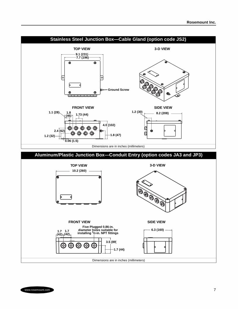
Stainless Steel Junction Box—Cable Gland (option code JS2)
Dimensions are in inches (millimeters)
Aluminum/Plastic Junction Box—Conduit Entry (option codes JA3 and JP3)
Dimensions are in inches (millimeters)
TOP VIEW
FRONT VIEW SIDE VIEW
3-D VIEW
7.7 (196)
1.2 (30)1.8(46)
1.1 (28)1.73 (44)
2.4 (62)
1.2 (32)
9.1 (231)
4.0 (102)
1.8 (47)
0.06 (1.5)
Ground Screw
8.2 (208)
TOP VIEW
FRONT VIEW SIDE VIEW
3-D VIEW
6.3 (160)1.7(42)
1.7(42)
10.2 (260)
1.7 (44)
Five Plugged 0.86-in.diameter holes suitable forinstalling 1/2-in. NPT fittings
3.5 (89)
Rosemount Model 848T Eight Input Temperature Transmitter with FOUNDATION Fieldbus
8 www.rosemount.comwww.rosemount.com
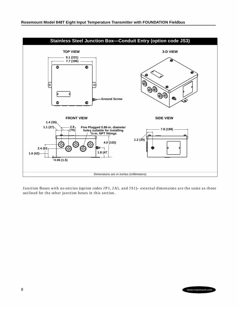
Junction Boxes with no entries (option codes JP1, JA1, and JS1)– external dimensions are the same as thoseoutlined for the other junction boxes in this section.
Stainless Steel Junction Box—Conduit Entry (option code JS3)
Dimensions are in inches (millimeters)
TOP VIEW
FRONT VIEW SIDE VIEW
3-D VIEW
1.1 (27)
9.1 (231)7.7 (196)
2.8(70)
1.6 (42)
0.06 (1.5)
7.8 (198)
1.2 (30)
1.4 (35)
Five Plugged 0.86-in. diameterholes suitable for installing
1/2-in. NPT fittings
4.0 (102)
Ground Screw
2.4 (62)1.8 (47)
Rosemount Inc.
9www.rosemount.comwww.rosemount.com
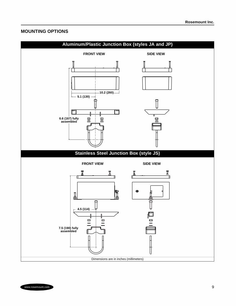
MOUNTING OPTIONS
Aluminum/Plastic Junction Box (styles JA and JP)
Stainless Steel Junction Box (style JS)
Dimensions are in inches (millimeters)
FRONT VIEW SIDE VIEW
10.2 (260)5.1 (130)
6.6 (167) fullyassembled
FRONT VIEW SIDE VIEW
4.5 (114)
7.5 (190) fullyassembled
Rosemount Model 848T Eight Input Temperature Transmitter with FOUNDATION Fieldbus
10 www.rosemount.comwww.rosemount.com
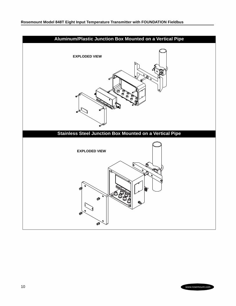
Aluminum/Plastic Junction Box Mounted on a Vertical Pipe
Stainless Steel Junction Box Mounted on a Vertical Pipe
EXPLODED VIEW
EXPLODED VIEW
Rosemount Inc.
11www.rosemount.comwww.rosemount.com
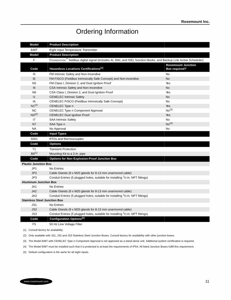
Ordering Information
Model Product Description
848T Eight Input Temperature Transmitter
Model Product Description
F FOUNDATION™ fieldbus digital signal (includes AI, MAI, and ISEL function blocks, and Backup Link Active Scheduler)
Code Hazardous Locations Certifications(1)
(1) Consult factory for availability.
Rosemount JunctionBox required?
I5 FM Intrinsic Safety and Non-Incendive No
IE FM FISCO (Fieldbus Intrinsically Safe Concept) and Non-incendive No
N5 FM Class I, Division 2, and Dust Ignition Proof Yes
I6 CSA Intrinsic Safety and Non-Incendive No
N6 CSA Class I, Division 2, and Dust Ignition Proof Yes
I1 CENELEC Intrinsic Safety No
IA CENELEC FISCO (Fieldbus Intrinsically Safe Concept) No
N1(2)
(2) Only available with JS1, JS2 and JS3 Stainless Steel Junction Boxes. Consult factory for availability with other junction boxes.
CENELEC Type n Yes
NC CENELEC Type n Component Approval No(3)
(3) The Model 848T with CENELEC Type n Component Approval is not approved as a stand-alone unit. Additional system certification is required.
ND(2) CENELEC Dust Ignition Proof Yes
I7 SAA Intrinsic Safety No
N7 SAA Type n No(4)
(4) The Model 848T must be installed such that it is protected to at least the requirements of IP54; All listed Junction Boxes fulfill this requirement.
NA No Approval No
Code Input Types
S001 RTDs and thermocouples
Code Options
T1 Transient Protection
B6(1) Mounting Kit to a 2-in. pipe
Code Options for Non Explosion-Proof Junction Box
Plastic Junction Box
JP1 No Entries
JP2 Cable Glands (9 x M20 glands for 8-13 mm unarmored cable)
JP3 Conduit Entries (5 plugged holes, suitable for installing 1/2-in. NPT fittings)
Aluminum Junction Box
JA1 No Entries
JA2 Cable Glands (9 x M20 glands for 8-13 mm unarmored cable)
JA3 Conduit Entries (5 plugged holes, suitable for installing 1/2-in. NPT fittings)
Stainless Steel Junction Box
JS1 No Entries
JS2 Cable Glands (9 x M20 glands for 8-13 mm unarmored cable)
JS3 Conduit Entries (5 plugged holes, suitable for installing 1/2-in. NPT fittings)
Code Configuration Options(5)
(5) Default configuration is the same for all eight inputs.
F5 50 Hz Line Voltage Filter
¢00813-0100-4697,¤00813-0100-4697, Rev. AA, 6/01
Product documentation available at...www.rosemount.com
PR
INTED
INU.S. A.
Rosemount Temperature GmbHFrankenstrasse 2163791 KarlsteinGermanyTel 49 (6188) 992 0Fax 49 (6188) 992 286
Fisher-RosemountSingapore Pte Ltd.1 Pandan CrescentSingapore 128461Tel (65) 777-8211Fax (65) [email protected]
Rosemount and the Rosemount logotype are registered trademarks of Rosemount Inc.PlantWeb is a mark of one of the Emerson Process Management companies.FOUNDATION is a trademark of the Fieldbus Foundation.DeltaV is a trademark of the Fisher-Rosemount group of companies.All other marks are the property of their respective owner.
Rosemount Inc.8200 Market BoulevardChanhassen, MN 55317USATel 1-800-999-9307Fax (952) 949-7001© 2000 Rosemount, Inc.
Transmitter TagHardware
• Tagged in accordance withcustomer requirements
• Permanently attached to the transmitterSoftware
• The transmitter can store up to 30characters. If no characters arespecified, the first 30 characters of thehardware tag will be used.
Sensor TagHardware
• Plastic tag to record identification ofeight sensors.
• Can be removed, printed onto, andreattached
Software• The transmitter can store up to 30
characters. If no characters arespecified, the first 30 characters of thehardware tag will be used.
Transmitter ConfigurationThe transmitter is available with thestandard configuration setting. Theconfiguration settings and blockconfiguration may be changed in the fieldwith the Fisher-Rosemount SystemsDeltaV®, with AMSinside®, or otherFOUNDATION fieldbus host orconfiguration tool.
Custom ConfigurationCustom configurations are to be specifiedwhen ordering. This configuration must bethe same for all eight sensors.
Standard ConfigurationUnless otherwise specified, the transmitterwill be shipped as follows for all eightsensors:
Standard Configuration Settings
Sensor Type(1)
(1) For all eight sensors
Pt 100 ( = 0.00385),3-wire RTD
Damping(1) 2 secondsMeasurementUnits(1)
°C
Output(1) Linear withTemperature
Line VoltageFilter(1)
60 Hz
TemperatureSpecific Blocks
• MeasurementTransducer Block (1)
• Sensor TransducerBlock (8)
• DifferentialTransducer Block (4)
FOUNDATION
fieldbusFunctionBlocks
• Analog Input (8)• Multiplexed Analog
Input (1)• Input Selector (4)