Embed Size (px)
Citation preview

48TCGas Heat/Electric CoolingPackaged Rooftop3 to 15 Nominal Tons
Product Data
C08613
the environmentally sound refrigerant

2
TABLE OF CONTENTSPAGE
FEATURES AND BENEFITS 3. . . . . . . . . . . . . . . . . . . .
MODEL NUMBER NOMENCLATURE 4. . . . . . . . . . . .
FACTORY OPTIONS AND/OR ACCESSORIES 6. . . . .
AHRI COOLING RATING TABLES 9. . . . . . . . . . . . . . .
HEAT RATING TABLE 10. . . . . . . . . . . . . . . . . . . . . . . .
SOUND PERFORMANCE TABLE 11. . . . . . . . . . . . . . .
PHYSICAL DATA 13. . . . . . . . . . . . . . . . . . . . . . . . . . . . .
CURBS & WEIGHTS DIMENSIONS 19. . . . . . . . . . . . .
PAGE
APPLICATION DATA 31. . . . . . . . . . . . . . . . . . . . . . . . .
COOLING TABLES 34. . . . . . . . . . . . . . . . . . . . . . . . . . .
STATIC PRESSURE ADDERS 55. . . . . . . . . . . . . . . . . .
FAN PERFORMANCE 59. . . . . . . . . . . . . . . . . . . . . . . . .
ELECTRICAL INFORMATION 72. . . . . . . . . . . . . . . . .
SEQUENCE OF OPERATION 102. . . . . . . . . . . . . . . . . .
GUIDE SPECIFICATIONS 105. . . . . . . . . . . . . . . . . . . . .
The Carrier rooftop unit (RTU) was designed by customers for customers. With “no--strip screw” collars, handled accesspanels, and more we’ve made your unit easy to install, easy to maintain and easy to use.
Easy to install:
All WeatherMakerr units are field--convertible to horizontal air flow which makes it easy to adjust to unexpected job sitecomplications. Lighter units make easy replacement. Most Carrier 48TC rooftops fit on existing Carrier curbs dating backto 1989. Also, our large control box gives you room to work and room to mount Carrier accessory controls.
Easy to maintain:
Easy access handles by Carrier provide quick and easy access to all normally serviced components. Our “no--strip” screwsystem has superior holding power and guides screws into position while preventing the screw from stripping the unit’smetal. Take accurate pressure readings by reading condenser pressure with panels on. Simply remove the black, compositeplug, route your gauge line(s) through the hole, and connect them to the refrigeration service valve(s).
Easy to use:
The newly designed, central terminal board by Carrier puts all your connections and troubleshooting points in oneconvenient place, standard. Most low voltage connections are made to the same board and make it easy to find what you’relooking for and easy to access it. Carrier rooftops have high and low pressure switches, a filter drier, and 2--in (51mm)filters standard.

3
FEATURES AND BENEFITSS Single cooling stage models are available from 3 -- 10 ton.
S Two cooling stage models are available from 7.5 -- 15 ton.
S SEER up to 13.0.
S EER’s up to 11.1.
S IEER’s up to 11.8 with single speed indoor fan motor and up to 12.8 with 2--speed/VFD indoor fan motor.
S Up to 28% lighter than similar industry units. Lighter rooftops make easier replacement jobs.
S Utility connections are the same because 3 -- 12.5 ton units fit on existing Carrier rooftop curbs. This saves time andmoney on replacement jobs.
S Standardized components and layout. Standardized components and controls make service and stocking parts easier.
S Scroll compressors on all units. This makes service, stocking parts, replacement, and troubleshooting easier.
S Field convertible airflow (3 -- 15 ton). Being able to convert a unit from vertical airflow to horizontal makes it easy toovercome job site complications. 15 ton models require a simple supply duct cover to field convert from factory verticalto horizontal.
S Easy--adjust, belt--drive motor available.
S Provisions for bottom or side condensate drain.
S Capable of thru--the--base or thru--the--curb gas line routing.
S Single--point gas / electrical connection.
S Sloped, composite drain pan sheds water; and won’t rust.
S Standardized controls & control box layout. Standardized components & controls make stocking parts & service easier.
S Tool--less filter access door.
S Clean, large, easy to use control box.
S Color--coded wiring.
S Large, laminated wiring and power wiring drawings which are affixed to unit make troubleshooting easy.
S Single, central terminal board for test and wiring connections.
S Fast--access, handled, panels for easy access on normally accessed service panels.
S “No--strip” screw system guides screws into the panel & captures them tightly without stripping the screw, the panel, or
the unit.
S Mechanical cooling (115_F to 40_F or 46_C to 4_C) standard on all models. Winter Start Kit allows cooling operationdown to 25_F (--4_C) and MotorMaster to --20_F (--29_C).
S High efficiency, gas heat with induced--draft flue exhaust design.
S Induced draft motor ensures no flue gas can escape into the indoor air stream.
S Carrier designed naturally draining heat exchanger, unlike positive pressure heat exchangers, do not need to beperiodically, manually drained. This saves labor and maintenance expense.
S 2--in (51mm) disposable filters on all units.
S Refrigerant filter--drier on each circuit.
S Each circuit is protected with a high and low pressure switch.
S Many factory--installed options ranging from air management economizers, 2 position dampers, plus convenienceoutlets, disconnect switches and smoke detectors.
S Standard (parts only) Warranty: 10 yr. aluminized heat exchanger, 5 yr. compressor, 3 yr. Novation condenser coil, 1 yr.parts.
S Factory--installed Humidi--MiZerr adaptive dehumidification system on all sizes with round tube / plate fin condensercoils, includes MotorMaster I controller.
S Optional Staged Air Volume (SAV) system utilizes a Variable Frequency Drive (VFD) to automatically adjust the indoor
fan motor speed between cooling stages. Available on 2--stage cooling models 08--16 with electromechanical controls orRTU Open.

4
MODEL NUMBER NOMENCLATURE
4 8 T C D A 0 4 A 1 A 5 --- 0 A 0 A 0
Unit Heat Type Packaging & Seismic
48 = Gas heat pkg. rooftop 0 = Standard1 = LTL3 = CA seismic compliant
Series Model 4 = LTL & CA seismic compliantTC = Standard Efficiency
Heat Size Electrical OptionsD = Low heat A = NoneE = Med heat C = Non---fused disconnectF = High heat D = Thru the base connL = Low NOx, Low heat F = Non fused disc & thru the baseM = Low NOx, Med heat G = 2 speed indoor fan (VFD) contrN = Low NOx, High heat J = 2 speed fan cntr (VFD) & non fused discS = Stainless steel, Low heat K = 2 spd fan cntr (VFD) & thru the base connR = Stainless steel, Med heat M = 2 speed fan (VFD) & non fused disc &T = Stainless steel, High heat thru the base conn
Refrigerant Systems Options Service OptionsA = Standard 1 stage cooling models 0 = NoneB = Standard 1 stg. Cooling w/Humidi---MiZer
(04---07 models only)1 = Unpowered conveniece oulet2 = Powered conveniece outlet
D = 2 stage cooling models (08---16 models only) 3 = Hinged panelsE = 2 stage cooling models w/ Al ---CU cond coil 4 = Hinged panels, unpowered C.O.& Humidi---MiZer (08---16 models only) 5 = Hinged panels, powered C.O
Cooling Tons04 = 3 Ton 09 = 8.5 Ton Intake / Exhaust Options05 = 4 Ton 12 = 10 Ton A = None06 = 5 Ton 14 = 12.5 Ton B = Temp Economizer w/ barometric relief07 = 6 Ton 16 = 15 Ton F = Enthalpy Econo w/ baro relief08 = 7.5 Ton K = 2 position damper
U = Temp ultra low leak econo w/baro reliefSensor Options W = Enthalpy ultra low leak econo w/baro reliefA = NoneB = RA smoke detector Base unit controlsC = SA smoke Detector 0 = Base electromechanical controlsD = RA + SA smoke detector 1 = PremierLink ControllerE = CO2 sensor 2 = RTU open multi---protocol controllerF = RA smoke detector & CO2 sensor 6 = Electromechanical with 2 speed fan & W7720 econo cntl.G = SA smoke detector & CO2 sensorH = RA + SA smoke detector & CO2 sensor Design Revision
Factory AssignedIndoor Fan Options1 = Standard static option Voltage2 = Medium static option 1 = 575/3/60 5 = 208---230/3/603 = High static option 3 = 208---230/1/60 6 = 460/3/60C = High Static option w/high efficiency motor (size 16 only)
Coil Options for Round Tube/Plate Fin Cond Coil Models Only(outdoor--- indoor---hailguard)A = Al/Cu --- Al/Cu M = Al/Cu --- Al/Cu --- Louvered hail guard
Note: On single phase (---3 voltage code) models, the following B = Precoat Al/Cu--- Al/Cu N = Precoat Al/Cu---Al/Cu---Louvered hail guardare not available as a factory installed option: C = Ecoat Al/Cu --- Al/Cu P = Ecoat Al/Cu --- Al/Cu --- Louvered hail guard--- Humidi---MiZer D=EcoatAl/Cu EcoatAl/Cu Q=Ecoat Al/Cu---Ecoat Al/Cu louvered hail guard--- Coated Coils or Cu Fin Coils E = Cu/Cu --- Al/Cu R = Cu/Cu --- Al/Cu --- Louvered hail guard--- Louvered Hail Guards F = Cu/Cu --- Cu/Cu S = Cu/Cu --- Cu/Cu --- Louvered hail guard--- Economizer or 2 Position Damper Coil Options for All Aluminum Novation Cond Coil Models Only--- Powered 115 Volt Convenience Outlet (outdoor--- indoor---hailguard)
G = Al/Al --- Al/Cu T = Al/Al --- Al/Cu, louvered hail guardH = Al/Al --- Cu/Cu U = Al/Al --- Al/Cu, louvered hail guardJ = Al/Al --- Ecoat Al/Cu V = Al/Al --- Ecoat Al/Cu, louvered hail guardK = Ecoat Al/Al --- Al/Cu W = Ecoat Al/Al --- Al/Cu, louvered hail guardL=Ecoat Al/Al---Ecoat Al/Cu X=Ecoat Al/Al --- Ecoat Al/Cu louvered hail guard
Not all possible options can be displayed above --- see price pages or contact your Carrier Expert for more details.

5
Table 1 – FACTORY--INSTALLED OPTIONS AND FIELD--INSTALLED ACCESSORIES
CATEGORY ITEMFACTORYINSTALLEDOPTION
FIELDINSTALLEDACCESSORY
Cabinet
Thru--- the---base electrical or gas--- line connections X XSupply Duct Cover (16 size only) XCalifornia Seismic Compliant Labeling XHinged Access Panels X
Coil OptionsCu/Cu indoor and/or outdoor coils1, 6 XPre---coated outdoor coils1, 6 XPremium, E---coated outdoor coils1, 6 X
Humidity Control Humidi---MiZer Adaptive Dehumidification System6 XCondenser Protection Condenser coil hail guard (louvered design)6 X X
Controls
Thermostats, temperature sensors, and subbases XPremierLink DDC communicating controller X XRTU Open---protocol controller XSmoke detector (supply and/or return air) XTime Guard II compressor delay control circuit XPhase Monitor X
Economizers& Outdoor AirDampers
EconoMi$ert IV (for electro---mechanical controlled RTUs)6 X XEconoMi$ert2 (for DDC controlled RTUs)6 X XMotorized 2 position outdoor air damper6 X XManual outdoor air damper (25% and 50%) XBarometric relief2 X XPower exhaust XUltra Low Leak EconoMi$er X (for 2---speed SAV system only08 to 16 sizes with 2 stages of cooling), vertical supply andreturn air only.
X X
EconomizerSensors&
IAQ Devices
Single dry bulb temperature sensors3 X XDifferential dry bulb temperature sensors3 XSingle enthalpy sensors3 X XDifferential enthalpy sensors3 XWall or duct mounted CO2 sensor3 XUnit mounted CO2 sensor3 X
Gas Heat
Propane conversion kit XStainless steel heat exchanger XHigh altitude conversion kit XFlue Shield (04---14 sizes only) XFlue Discharge Deflector (04---14 sizes only) X
Indoor Motor& Drive
Multiple motor and drive packages XStaged Air Vol (SAV) system w/VFD controller (2---stage coolonly with electrical mechanical and RTU Open controls) X
Display Kit for SAV system with VFD XLow AmbientControl
Winter start kit4 XMotormaster head pressure controller4 X
PowerOptions
Convenience outlet (powered)6 XConvenience outlet (un---powered) XNon--- fused disconnect5 XDisconnect Switch Bracket (16 size only) X
Roof CurbsRoof curb 14--- in (356mm) XRoof curb 24--- in (610mm) X
NOTES:1. Novation coated coils only available with E---coat.2. Included with economizer.3. Sensors used to optimize economizer performance.4. See application data for assistance.5. Available on units with MOCP’s of 80 amps or less.6. Not available as factory installed option on single phase (208/230/1/60) models. Use field--- installed accessory where available.

6
FACTORY OPTIONS AND/OR ACCESSORIESEconomizer (dry--bulb or enthalpy)
Economizers save money. They bring in fresh, outside airfor ventilation; and provide cool, outside air to cool yourbuilding. This is the preferred method of low ambientcooling. When coupled to CO2 sensors, economizers canprovide even more savings by coupling the ventilation airto only that amount required.
Economizers are available, installed and tested by thefactory, with either enthalpy or dry--bulb temperatureinputs. There are also models for electromechanical aswell as direct digital controllers. Additional sensors areavailable as accessories to optimize the economizers.
Economizers include gravity controlled, barometric reliefwhich equalizes building pressure and ambient airpressures. This can be a cost effective solution to preventbuilding pressurization.
CO2 Sensor
Improves productivity and saves money by working withthe economizer to intake only the correct amount ofoutside air for ventilation. As occupants fill your building,the CO2 sensor detects their presence through increasingCO2 levels, and opens the economizer appropriately.
When the occupants leave, the CO2 levels decrease, andthe sensor appropriately closes the economizer. Thisintelligent control of the ventilation air, called DemandControl Ventilation (DCV) reduces the overall load on therooftop, saving money.
Smoke Detectors
Trust the experts. Smoke detectors make your applicationsafer and your job easier. Carrier smoke detectorsimmediately shut down the rooftop unit when smoke isdetected. They are available, installed by the factory, forsupply air, return air, or both.
Louvered Hail Guards
Sleek, louvered panels protect the condenser coil fromhail damage, foreign objects, and incidental contact.
Convenience Outlet (powered or un--powered)
Reduce service and/or installation costs by including aconvenience outlet in your specification. Carrier willinstall this service feature at our factory. Provides aconvenient, 15 amp, 115v GFCI receptacle with “Wet inUse” cover. The “powered” option allows the installer topower the outlet from the line side of the disconnect orload side as required by code. The “un--powered” option isto be powered from a separate 115/120v power source.
Non--fused Disconnect
This OSHA--compliant, factory installed, safety switchallows a service technician to locally secure power to therooftop.
Disconnect Switch Bracket
Provides a pre--engineered and sized mounting bracket forapplications requiring a unit mounted fused and non--fuseddisconnect of greater than 100 amps. Bracket assures thatno damage will occur to coils when mounting with screwsand other fasteners (16 size only).
Power Exhaust with Barometric Relief
Superior internal building pressure control. This fieldinstalled accessory may eliminate the need for costly,external pressure control fans.
PremierLink, DDC Controller
This CCN controller regulates your rooftop’s performanceto tighter tolerances and expanded limits, as well asfacilitates zoning systems and digital accessories. It alsounites your Carrier HVAC equipment together on one,coherent CCN network. The PremierLink can be factoryinstalled, or easily field installed. Not available with2--speed Staged Air Volume (SAV) system.
RTU Open, Multi--Protocol Controller
Connect the rooftop to an existing BAS without needingcomplicated translators or adapter modules using the RTUOpen controller. This new controller speaks the 4 mostcommon building automation system languages (Bacnet,Modbus, N2, and Lonworks). Use this controller whenyou have an existing BAS.
Time Guard II Control Circuit
This accessory protects your compressor by preventingshort--cycling in the event of some other failure, preventsthe compressor from restarting for 30 seconds afterstopping. Not required with PremierLink, RTU Open, orauthorized commercial thermostats.
Motorized 2--Position Damper
The new Carrier 2--position, motorized outdoor air damperadmits up to 100% outside air. Using reliable, gear--driventechnology, the 2--position damper opens to allowventilation air and closes when the rooftop stops, stoppingunwanted infiltration.
Manual OA Damper
Manual outdoor air dampers are an economical way tobring in ventilation air. The dampers are available in 25%and 50% versions.
Optional Humidi--MiZer AdaptiveDehumidification System
Carrier’s Humidi--MiZer Adaptive DehumidificationSystem is an all--inclusive factory installed option that canbe ordered with any WeatherMaker 48TC**04--16 rooftopunit.
7
FACTORY OPTIONS AND/OR ACCESSORIES (cont.)
Opt. Humidi--MiZer Adap. Dehum. Sys. (cont.)This system expands the envelope of operation ofCarrier’s WeatherMaker rooftop products to provideunprecedented flexibility to meet year round comfortconditions.
The Humidi--MiZer adaptive dehumidification system hasthe industry’s only dual dehumidification mode setting.The Humidi--MiZer system includes two new modes ofoperation.
The WeatherMaker 48TC**04--16 rooftop coupled withthe Humidi--MiZer system is capable of operating innormal design cooling mode, subcooling mode, and hotgas reheat mode. Normal design cooling mode is when theunit will operate under its normal sequence of operationby cycling compressors to maintain comfort conditions.
Subcooling mode will operate to satisfy part load typeconditions when the space requires combined sensible anda higher proportion of latent load control. Hot Gas Reheatmode will operate when outdoor temperatures diminishand the need for latent capacity is required for solehumidity control. Hot Gas Reheat mode will provideneutral air for maximum dehumidification operation.
Staged Air Volume (SAV) Indoor Fan SpeedSystem
Carrier’s Staged Air Volume (SAV) system saves energyand installation time by utilizing a Variable FrequencyDrive (VFD) to automatically adjust the indoor fan motorspeed in sequence with the units cooling operation. PerASHRAE 90.1 2010 standard section 6.4.3.10.b, duringthe first stage of cooling operation the VFD will adjust thefan motor to provide 2/3rd of the total cfm established forthe unit. When a call for the second stage of cooling isrequired, the VFD will allow the total cfm for the unitestablished (100%). During the heating mode the VFDwill allow total design cfm (100%) operation and duringthe ventilation mode the VFD will allow operation to2/3rd of total cfm.
Compared to single speed indoor fan motor systems,Carrier’s SAV system can save substantial energy, 25%+*,versus single speed indoor fan motor systems.
The VFD used in Carrier’s SAV system has soft startcapabilities to slowly ramp up the speeds, thus eliminatingany high inrush air volume during initial start--up. It alsohas internal over--current protection for the fan motor anda field installed display kit that allows adjustment and indepth diagnostics of the VFD.
This SAV system is available on models with 2--stagecooling operation with electromechanical or RTU Open,Multi Protocol controls. Both space sensor andconventional thermostats/controls can be used to provideaccurate control in any application.
The SAV system is very flexible for initial fanperformance set up and adjustment. The standard factoryshipped VFD is pre--programmed to automatically stagethe fan speed between the first and second stage ofcooling. The unit fan performance static pressure and cfmcan be easily adjusted using the traditional means ofpulley adjustments. The other means to adjust the unitstatic and cfm performance is to utilize the field installedDisplay Kit and adjust the frequency and voltage in theVFD to performance requirements. In either case, once setup, the VFD will automatically adjust the speed betweenthe cooling stage operations.*Data based on .10 ($/kWh) in an office applicationutilizing Carrier’s HAP 4.6 simulation software program
Motormaster Head Pressure Controller
The Motormaster motor controller is a low ambient, headpressure controller kit that is designed to maintain theunit’s condenser head pressure during periods of lowambient cooling operation. This device should be used asan alternative to economizer free cooling wheneconomizer usage is either not appropriate or desired. TheMotormaster will either cycle the outdoor fan motors oroperate them at reduced speed to maintain the unitoperation, depending on the model.
Winter Start Kit
The winter start kit by Carrier extends the low ambientlimit of your rooftop to 25_F (--4_C). The kit bypasses thelow pressure switch, preventing nuisance tripping of thelow pressure switch. Other low ambient precautions maystill be prudent.
Propane Heating
Convert your gas heat rooftop from standard natural gasoperation to propane using this field installed kit.
High Altitude Heating
High altitudes have less oxygen, which means heatexchangers need less fuel. The new gas orifices in thisfield installed kit make the necessary adjustment for highaltitude applications. They restore the optimal fuel to airmixture and maintain healthy combustion at altitudesabove 2000 ft (610m). Kits may not be required in allareas.
Hinged Access Panels
Allows access to unit’s major components withspecifically designed hinged access panels. Panels are:filter, control box, fan motor, and compressor.

8
FACTORY OPTIONS AND/OR ACCESSORIES (cont.)Flue Discharge Deflector
The flue discharge deflector is a useful accessory whenflue gas recirculation is a concern. By venting the fluedischarge upwards, the deflector minimizes the chance fora neighboring unit to intake the flue exhaust (04--14 sizesonly).
Optional Stainless Steel Heat Exchanger
The stainless steel heat exchanger option provides thetubular heat exchanger be made out of a minimum 20gauge type 409 stainless steel for applications where themixed air to the heat exchanger is expected to drop below45_F (7_C). Stainless steel may be specified onapplications where the presence of airborne contaminantsrequire its use (applications such as paper mills) or inareas with very high outdoor humidity that may result insevere condensation in the heat exchanger during coolingoperation.
Flue Discharge Heat Shield
The flue discharge heat shield keeps people from touchingthe rooftop unit’s potentially hot flue discharge. This isespecially useful for ground level applications, wheremore, untrained people could have access to the unit’sexterior (04--14 sizes only).
Alternate Motors and Drives
Some applications need larger horsepower motors, someneed more airflow, and some need both. Regardless of thecase, your Carrier expert has a factory installedcombination to meet your application. A wide selection ofmotors and pulleys (drives) are available, factoryinstalled, to handle nearly any application.
Thru--the--Base Connections
Thru--the--base connections, available as either anaccessory or as a factory option, are necessary to ensureproper connection and seal when routing wire and pipingthrough the rooftop’s basepan and curb. These couplingseliminate roof penetration and should be considered forgas lines, main power lines, as well as control power.
Supply Duct Cover
This supply duct cover is required when field convertingthe factory standard vertical duct supply to horizontal ductsupply configuration. One required per unit (16 size only).
California OSHPD Seismic CertificationLabel
Units meet the seismic requirements of the InternationalCode Council Evaluation Service (ICC--ES) documentAC156 (Acceptance Criteria for Seismic Qualification byShake--Table Testing of Nonstructural Components andSystems) and per International Building Code (IBC 2009)at an SDS (g) value of 2.00 z/h=1.0, Ip=1.5 and certifiedby independent structural engineers. A certification labelis applied to the unit that meets the CA OSHPD SpecialSeismic Certification pre--approval labeling requirementson the external chassis of the unit.

9
Table 2 – AHRI COOLING RATING TABLE
UNIT COOLINGSTAGES
NOM.CAPACITY(TONS)
NETCOOLINGCAPACITY(MBH)
TOTALPOWER (KW) SEER EER IEER
A04 1 3 34.6 3.1 13.0 11.00 N/AA05 1 4 45.0 4.0 13.0 11.00 N/AA06 1 5 59.0 5.5 13.0 10.75 N/AA07 1 6 70.0 6.4 N/A 11.00 11.2A08 1 7.5 88.0 8.0 N/A 11.00 11.2A09 1 8.5 97.0 8.8 N/A 11.00 11.2A12 1 10 117.0 10.6 N/A 11.00 11.2
UNIT COOLINGSTAGES
NOM.CAPACITY(TONS)
NETCOOLINGCAPACITY(MBH)
TOTALPOWER(KW)
EER
IEER WITHSINGLE SPEEDINDOOR FANMOTOR
IEER WITH2 SPEED
INDOOR FANMOTOR
D08 2 7.5 83.0 7.5 11.00 11.7 12.8D09 2 8.5 97.0 9.0 11.00 11.2 12.8D12 2 10 114.0 10.3 11.10 11.8 12.8D14 2 12.5 140.0 12.9 10.80 11.0 11.8D16 2 15 174.0 16.1 10.80 11.7 12.4
LEGENDAHRI --- Air Conditioning, Heating and Refrigeration
Institute Test StandardASHRAE --- American Society of Heating, Refrigerating
and Air Conditioning, Inc.EER --- Energy Efficiency RatioIEER --- Integrated Energy Efficiency RatioN/A --- Not ApplicableSEER --- Seasonal Energy Efficiency Ratio
Use of the AHRI CertifiedTM Mark indicates amanufacturer’s participation in the program For verification of certification for individual products, go to www.ahridirectory.org.
NOTES:1. Rated in accordance with AHRI Standard 210/240 or340/360, as appropriate.
2. Ratings are based on:Cooling Standard: 80_F (27_C) db, 67_F (19_C) wb indoorair temp and 95_F (35_C) db outdoor air temp.IEER Standard: A measure that expresses cooling part---load EER efficiency for commercial unitary air conditioningand heat pump equipment on the basis of weighted opera-tion at various load capacities.
3. All 48TC units comply with ASHRAE 90.1 Energy Standardfor minimum SEER and EER requirements.
4. 48TC units comply with US Energy Policy Act (2005). To eval-uate code compliance requirements, refer to state and localcodes.

10
Table 3 – HEATING RATING TABLE -- NATURAL GAS & PROPANE
UNITS GAS HEATAL/SS HEAT EXCHANGER
TEMP RISE(DEG F)
THERMALEFFICIENCY
(%)
AFUE(%)INPUT / OUTPUT
STAGE 1 (MBH)INPUT / OUTPUTSTAGE 2 (MBH)
SinglePhase
04LOW --- 72 / 56 25 --- 55 82% 79.1%MED --- 115 / 89 55 --- 85 80% 78.5%HIGH --- --- --- --- ---
05LOW --- 72 / 56 25 --- 55 82% 79.1%MED --- 115 / 90 35 --- 65 81% 79%HIGH --- 150 / 117 50 --- 80 80% 78.8%
06LOW --- 72 / 56 20 --- 55 82% 79.1%MED --- 115 / 90 30 --- 65 81% 79%HIGH --- 150 / 117 40 --- 80 80% 78.8%
ThreePhase
04LOW --- 72 / 56 25 --- 55 82% N/AMED 82 / 66 115 / 89 55 --- 85 80% N/AHIGH --- --- --- --- ---
05LOW --- 72 / 56 25 --- 55 82% N/AMED --- 115 / 90 35 --- 65 81% N/AHIGH 120 / 96 150 / 117 50 --- 80 80% N/A
06LOW --- 72 / 56 20 --- 55 82% N/AMED --- 115 / 90 30 --- 65 81% N/AHIGH 120 / 96 150 / 117 40 --- 80 80% N/A
07LOW --- 72 / 59 15 --- 55 82% N/AMED --- 115 / 93 25 --- 65 81% N/AHIGH 120 / 96 150 / 120 35 --- 80 80% N/A
08LOW --- 125 / 103 20 --- 50 82% N/AMED 120 / 98 180 / 148 35 --- 65 82% N/AHIGH 180 / 147 224 / 184 45 --- 75 82% N/A
09LOW --- 125 / 103 20 --- 50 82% N/AMED 120 / 98 180 / 148 30 --- 65 82% N/AHIGH 180 / 147 224 / 184 40 --- 75 82% N/A
12LOW 120 / 98 180 / 148 25 --- 65 82% N/AMED 180 / 147 224 / 184 30 --- 65 82% N/AHIGH 200 / 160 250 / 205 35 --- 70 80% N/A
14LOW 120 / 98 180 / 148 20 --- 65 82% N/AMED 180 / 147 224 / 184 25 --- 65 82% N/AHIGH 200 / 160 250 / 205 25 --- 70 80% N/A
16LOW 144 / 118 180 / 146 15 --- 55 81% N/AMED 192 / 156 240 / 195 20 --- 60 81% N/AHIGH 280 / 224 350 / 280 35 --- 65 80% N/A
NOTES:Heat ratings are for natural gas heat exchangers operated at or below 2000 ft (610 m). For information on propane or altitudes above 2000ft (610 m), see the Application Data section of this book. Accessory Propane/High Altitude kits are also available.
In the USA the input rating for altitudes above 2000 ft (610m) must be derated by 4% for each 1000 ft (305 m) above sea level. In Canada,the input rating must be derated by 10% for altitudes of 2000 ft (610 m) to 4500 ft (1372 m) above sea level.

11
Table 4 – HEATING RATING TABLE -- LOW NOX1
UNIT GASHEAT
LOW NOx HEAT EXCHANGERTEMP RISE(DEG F)
THERMALEFFICIENCY (%)
AFUE(%)INPUT / OUTPUT
STAGE 1 (MBH)INPUT / OUTPUTSTAGE 2 (MBH)
SinglePhase
04LOW --- 60 / 47 20 --- 50 81% 80.6%MED --- 90 / 72 30 --- 60 81% 80.6%HIGH --- --- --- --- ---
05LOW --- 60 / 47 20 --- 50 81% 80.6%MED --- 90 / 72 30 --- 60 81% 80.6%HIGH --- 120 / 97 40 --- 70 81% 81.5%
06LOW --- 60 / 47 15 --- 50 81% 80.6%MED --- 90 / 72 25 --- 60 80% 80.6%HIGH --- 120 / 97 35 --- 70 80% 81.5%
ThreePhase
04LOW --- 60 / 47 20 --- 50 81% N/AMED --- 90 / 72 30 --- 60 81% N/AHIGH --- --- --- --- ---
05LOW --- 60 / 47 20 --- 50 81% N/AMED --- 90 / 72 30 --- 60 81% N/AHIGH --- 120 / 97 40 --- 70 81% N/A
06LOW --- 60 / 47 15 --- 50 81% N/AMED --- 90 / 72 25 --- 60 80% N/AHIGH --- 120 / 97 35 --- 70 80% N/A
NOTE:1. Units meet California’s South Coast Air Quality Management District (SCAQMD) Low---NOx emissions requirement of 40 nanograms perjoule or less.
--- Not Applicable
Table 5 – SOUND PERFORMANCE TABLE
UNIT COOLINGSTAGES
OUTDOOR SOUND (dB)A---WEIGHTED 63 125 250 500 1000 2000 4000 8000
A04 1 80 90.6 80.9 80.2 76 74.6 71.3 68.5 63.9A05 1 81 90.9 84.6 79.5 77.9 76.5 71.1 66.9 62.5A06 1 78 84.0 82.2 76.3 74.8 72.5 68.8 65.6 61.8A07 1 78 88.8 81.8 76.9 74.4 73.3 69.8 66.3 62.7A08 1 82 90.1 82.6 81.0 79.4 77.0 73.0 70.4 66.7D08 2 82 85.8 84.3 80.5 78.7 76.4 72.7 68.3 65.1A09 1 83 91.2 86.4 81.9 81.0 78.3 73.9 71.4 67.3D09 2 82 88.6 85.0 81.6 79.5 77.4 74.1 71.0 66.3A12 1 82 88.6 85.0 81.6 79.5 77.4 74.1 71.0 66.3D12 2 82 89.0 83.1 80.5 78.5 75.5 71.6 69.6 69.3D14 2 87 87.0 85.2 84.6 84.9 82.2 78.4 75.3 72.9D16 2 87 87.0 85.2 84.6 84.9 82.2 78.4 75.3 72.9
LEGENDdB --- Decibel
NOTES:1. Outdoor sound data is measure in accordance with AHRIstandard 270---2008.
2. Measurements are expressed in terms of sound power. Donot compare these values to sound pressure values becausesound pressure depends on specific environmental factorswhich normally do not match individual applications. Soundpower values are independent of the environment and there-fore more accurate.
3. A---weighted sound ratings filter out very high and very lowfrequencies, to better approximate the response of “average”human ear. A---weighted measurements for Carrier units aretaken in accordance with AHRI standard 270---2008.

12
Table 6 – MINIMUM -- MAXIMUM AIRFLOW RATINGS -- NATURAL GAS & PROPANE
UNIT HEAT LEVEL
COOLING HEATING
MinimumSingle SpeedFan Motor
Minimum2---speed FanMotor (at highspeed)
Minimum2---speed FanMotor (at lowspeed)
Maximum Minimum Minimum
48TC**04LOW
900 --- --- 1500990 2190
MED 1000 1550HIGH --- ---
48TC**05LOW
1200 --- --- 2000990 2190
MED 1330 2460HIGH 1390 2220
48TC**06LOW
1500 --- --- 2500990 2730
MED 1330 2880HIGH 1390 2780
48TC**07LOW
1800 --- --- 3000990 3640
MED 1330 3450HIGH 1390 3170
48TC**08LOW
2250 2250 1485 37501900 4750
MED 2100 3900HIGH 2270 3780
48TC**09LOW
2550 2873 1896 42501900 4750
MED 2100 4560HIGH 2270 4250
48TC**12LOW
3000 3380 2231 50002100 5470
MED 2620 5670HIGH 2650 5290
48TC**14LOW
3600 4225 2789 60002100 6830
MED 2620 6800HIGH 2650 7410
48TC**16LOW
4500 5625 3713 75002450 7500
MED 3000 6750HIGH 3990 7200
13
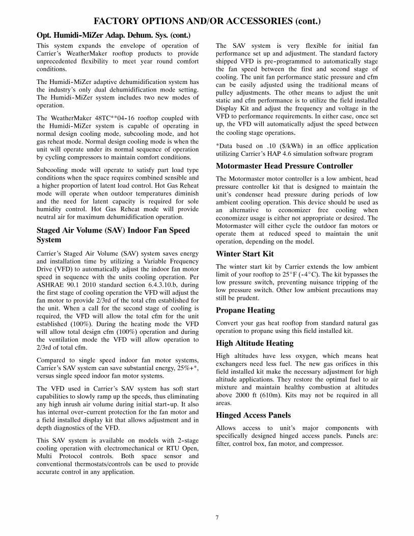
Table 7 – PHYSICAL DATA (COOLING) 3 -- 6 TONS48TC*A04 48TC*A05 48TC*A06 48TC*A07
Refrigeration System# Circuits / # Comp. / Type 1 / 1 / Scroll 1 / 1 / Scroll 1 / 1 / Scroll 1 / 1 / Scroll
Puronr refrig. (R---410A) (lbs---oz) 5---10 8---8 10---11 14---2Humidi---MiZer Puronr refrig. charge A/B (lbs --- oz) 8---11 14---13 16---0 22---5
Metering Device Acutrol Acutrol Acutrol AcutrolHigh---press. Trip / Reset (psig) 630 / 505 630 / 505 630 / 505 630 / 505Low---press. Trip / Reset (psig) 54 / 117 54 / 117 54 / 117 54 / 117
Compressor Capacity Staging (%) 100% 100% 100% 100%Evap. Coil
Material (Tube/Fin) Cu / Al Cu / Al Cu / Al Cu / AlCoil type 3/8--- in RTPF 3/8--- in RTPF 3/8--- in RTPF 3/8--- in RTPFRows / FPI 2 / 15 2 / 15 4 / 15 4 / 15
Total Face Area (ft2) 5.5 5.5 5.5 7.3Condensate Drain Conn. Size 3/4--- in 3/4--- in 3/4--- in 3/4--- in
Evap. Fan and Motor
StandardStatic
1phase
Motor Qty / Drive Type 1 / Belt 1 / Belt 1 / Belt ---Max BHP 1.2 1.2 1.2 ---
RPM Range 560---854 560---854 770---1175 ---Motor Frame Size 48 48 48 ---Fan Qty / Type 1 / Centrifugal 1 / Centrifugal 1 / Centrifugal ---
Fan Diameter (in) 10 x 10 10 x 10 10 x 10 ---
MediumStatic
1phase
Motor Qty / Drive Type 1 / Belt 1 / Belt 1 / Belt ---Max BHP 1.2 1.2 1.5 ---
RPM Range 770---1175 770---1175 1035---1466 ---Motor Frame Size 48 48 56 ---Fan Qty / Type 1 / Centrifugal 1 / Centrifugal 1 / Centrifugal ---
Fan Diameter (in) 10 x 10 10 x 10 10 x 10 ---
StandardStatic
3phase
Motor Qty / Drive Type 1 / Belt 1 / Belt 1 / Belt 1 / BeltMax BHP 1.2 1.2 1.5 2.4
RPM Range 560---854 560---854 770---1175 1073---1457Motor Frame Size 48 48 48 56Fan Qty / Type 1 / Centrifugal 1 / Centrifugal 1 / Centrifugal 1 / Centrifugal
Fan Diameter (in) 10 x 10 10 x 10 10 x 10 10 x 10
MediumStatic
3phase
Motor Qty / Drive Type 1 / Belt 1 / Belt 1 / Belt 1 / BeltMax BHP 1.2 1.2 2.4 2.9*
RPM Range 770---1175 770---1175 1035---1466 1173---1518Motor Frame Size 48 48 56 56Fan Qty / Type 1 / Centrifugal 1 / Centrifugal 1 / Centrifugal 1 / Centrifugal
Fan Diameter (in) 10 x 10 10 x 10 10 x 10 10 x 10
HighStatic
3phase
Motor Qty / Drive Type 1 / Belt 1 / Belt 1 / Belt 1 / BeltMax BHP 2.4 2.4 2.9 3.7
RPM Range 1035---1466 1035---1466 1303---1687 1474---1788Motor Frame Size 56 56 56 56Fan Qty / Type 1 / Centrifugal 1 / Centrifugal 1 / Centrifugal 1 / Centrifugal
Fan Diameter (in) 10 x 10 10 x 10 10 x 10 10 x 10
Cond. CoilMaterial (Tube/Fin) Cu / Al Cu / Al Cu / Al Cu / Al
Coil type 3/8--- in RTPF 3/8--- in RTPF 3/8--- in RTPF 3/8--- in RTPFRows / FPI 1 / 17 2 / 17 2 / 17 2 / 17
Total Face Area (ft2) 14.6 16.5 16.5 21.3Humidi---MiZer Coil
Material (Tube/Fin) Cu / Al Cu / Al Cu / Al Cu / AlRows..Fins/in. 1 / 17 2 / 17 2 / 17 2 / 17
Total Face Area (ft2) 3.9 3.9 3.9 5.2Cond. fan / motor
Qty / Motor Drive Type 1/ Direct 1/ Direct 1/ Direct 1/ DirectMotor HP / RPM 1/4 / 1100 1/4 / 1100 1/4 / 1100 1/4 / 1100Fan diameter (in) 22 22 22 22
FiltersRA Filter # / Size (in) 2 / 16 x 25 x 2 2 / 16 x 25 x 2 2 / 16 x 25 x 2 4 / 16 x 16 x 2
OA inlet screen # / Size (in) 1 / 20 x 24 x 1 1 / 20 x 24 x 1 1 / 20 x 24 x 1 1 / 20 x 24 x 1NOTE: Humidi---MiZer is not available with Novation condenser coil models, only Round Tube / Plate Fin (RTPF).* 575V motor utilizes 3.7 BHP.--- Not applicable

14
Table 8 – PHYSICAL DATA (HEATING) 3 -- 6 TONS48TC**04 48TC**05 48TC**06 48TC**07
Gas Connection# of Gas Valves 1 1 1 1
Nat. gas supply line press (in. w.g.)/ (PSIG) 4 ---13 / 0.18 --- 0.47 4 ---13 / 0.18 --- 0.47 4 ---13 / 0.18 --- 0.47 4 ---13 / 0.18 --- 0.47LP supply line press (in. w.g.) / (PSIG) 11 ---13 / 0.40 --- 0.47 11 ---13 / 0.40 --- 0.47 11 ---13 / 0.40 --- 0.47 11 ---13 / 0.40 --- 0.47
Heat Anticipator setting (Amps)1st stage 0.14 0.14 0.14 0.142nd stage 0.14 0.14 0.14 0.14
Natural Gas Heat
LOW
# of stages / # of burners (total) 1 / 2 1 / 2 1 / 2 1 / 2Connection Size 1/2--- in NPT 1/2--- in NPT 1/2--- in NPT 1/2--- in NPT
Rollout switch opens / closes 195 / 115 195 / 115 195 / 115 195 / 115Temperature Rise 25 --- 55 25 --- 55 20 --- 55 15 --- 55
MED
# of stages / # of burners (total) 1 or 2 / 3 1 / 3 1 / 3 1 / 3Connection Size 1/2--- in NPT 1/2--- in NPT 1/2--- in NPT 1/2--- in NPT
Rollout switch opens / closes 195 / 115 195 / 115 195 / 115 195 / 115Temperature Rise 55 --- 85 35 --- 65 30 --- 65 25 --- 65
HIGH
# of stages / # of burners (total) --- 1 or 2 / 3 1 or 2 / 3 2 / 3Connection Size --- 1/2--- in NPT 1/2--- in NPT 1/2--- in NPT
Rollout switch opens / closes --- 195 / 115 195 / 115 195 / 115Temperature Rise --- 50 --- 80 40 --- 80 35 --- 80
Liquid Propane Heat
LOW
# of stages / # of burners (total) 1 / 2 1 / 2 1 / 2 1 / 2Connection Size 1/2--- in NPT 1/2--- in NPT 1/2--- in NPT 1/2--- in NPT
Rollout switch opens / closes 195 / 115 195 / 115 195 / 115 195 / 115Temperature Rise 25 --- 55 25 --- 55 20 --- 55 15 --- 55
MED
# of stages / # of burners (total) 1 or 2 / 3 1 / 3 1 / 3 1 / 3Connection Size 1/2--- in NPT 1/2--- in NPT 1/2--- in NPT 1/2--- in NPT
Rollout switch opens / closes 195 / 115 195 / 115 195 / 115 195 / 115Temperature Rise 55 --- 85 35 --- 65 30 --- 65 25 --- 65
HIGH
# of stages / # of burners (total) --- 1 or 2 / 3 1 or 2 / 3 2 / 3Connection Size --- 1/2--- in NPT 1/2--- in NPT 1/2--- in NPT
Rollout switch opens / closes --- 195 / 115 195 / 115 195 / 115Temperature Rise --- 50 --- 80 40 --- 80 35 --- 80
Low NOx Gas Heat
LOW
# of stages / # of burners (total) 1 / 2 1 / 2 1 / 2 ---Connection Size 1/2--- in NPT 1/2--- in NPT 1/2--- in NPT ---
Rollout switch opens / closes 195 / 115 195 / 115 195 / 115 ---Temperature Rise 20 --- 50 20 --- 50 15 --- 50 ---
MED
# of stages / # of burners (total) 1 / 3 1 / 3 1 / 3 ---Connection Size 1/2--- in NPT 1/2--- in NPT 1/2--- in NPT ---
Rollout switch opens / closes 195 / 115 195 / 115 195 / 115 ---Temperature Rise 30 --- 60 30 --- 60 25 --- 60 ---
HIGH
# of stages / # of burners (total) --- 1 / 3 1 / 3 ---Connection Size --- 1/2--- in NPT 1/2--- in NPT ---
Rollout switch opens / closes --- 195 / 115 195 / 115 ---Temperature Rise --- 40 --- 70 35 --- 70 ---
--- Not applicable

15
Table 9 – PHYSICAL DATA (COOLING) 7.5 -- 8.5 TONS48TC*A08 48TC*D08 48TC*A09 48TC*D09
Refrigeration System# Circuits / # Comp. / Type 1 / 1 / Scroll 2 / 2 / Scroll 1 / 1 / Scroll 2 / 2 / Scroll
RTPF models R---410a charge A/B (lbs --- oz) 13 --- 12 8 --- 5 / 8 --- 2 15 --- 4 10 --- 5 / 10 --- 12Alternate (MCHX) R---410a charge A/B (lbs --- oz) 4 --- 6 / 4 --- 6
Alternate (Humidi---MiZer) R---410a charge A/B (lbs --- oz) 13 --- 3 / 13 --- 3 16 --- 13 / 16 --- 13Metering device Acutrol Acutrol Acutrol Acutrol
High---press. Trip / Reset (psig) 630 / 505 630 / 505 630 / 505 630 / 505Low---press. Trip / Reset (psig) 54 / 117 54 / 117 54 / 117 54 / 117
Compressor Capacity Staging (%) 100% 50% / 100% 100% 50% / 100%Evap. Coil
Material Cu / Al Cu / Al Cu / Al Cu / AlCoil type 3/8--- in RTPF 3/8--- in RTPF 3/8--- in RTPF 3/8--- in RTPFRows / FPI 3 / 15 3 / 15 3 / 15 3 / 15
Total face area (ft2) 8.9 8.9 11.1 11.1Condensate drain conn. size 3/4--- in 3/4--- in 3/4--- in 3/4--- in
Humidi---MiZer CoilMaterial --- Cu / Al --- Cu / AlCoil type --- 3/8--- in RTPF --- 3/8--- in RTPFRows / FPI --- 2 / 17 --- 2 / 17
Total face area (ft2) --- 6.3 --- 8.4Evap. fan and motor
StandardStatic
3phase
Motor Qty / Drive Type 1 / Belt 1 / Belt 1 / Belt 1 / BeltMax BHP 1.7 1.7 1.7 1.7RPM range 489---747 489---747 518---733 518---733
Motor frame size 56 56 56 56Fan Qty / Type 1 / Centrifugal 1 / Centrifugal 1 / Centrifugal 1 / Centrifugal
Fan Diameter (in) 15 x 15 15 x 15 15 x 15 15 x 15
MediumStatic
3phase
Motor Qty / Drive type 1 / Belt 1 / Belt 1 / Belt 1 / BeltMax BHP 2.9* 2.9* 2.4 2.4RPM range 733---949 733---949 690---936 690---936
Motor frame size 56 56 56 56Fan Qty / Type 1 / Centrifugal 1 / Centrifugal 1 / Centrifugal 1 / Centrifugal
Fan Diameter (in) 15 x 15 15 x 15 15 x 15 15 x 15
HighStatic
3phase
Motor Qty / Drive type 1 / Belt 1 / Belt 1 / Belt 1 / BeltMax BHP 4.7 4.7 3.7 3.7RPM range 909---1102 909---1102 838---1084 838---1084
Motor frame size 14 14 56 56Fan Qty / Type 1 / Centrifugal 1 / Centrifugal 1 / Centrifugal 1 / Centrifugal
Fan Diameter (in) 15 x 15 15 x 15 15 x 15 15 x 15
Cond. CoilMaterial Cu / Al Cu / Al Cu / Al Cu / AlCoil type 3/8--- in RTPF 3/8--- in RTPF 3/8--- in RTPF 3/8--- in RTPFRows / FPI 2 / 17 2 / 17 2 / 17 2 / 17
Total face area (ft2) 20.5 20.5 21.4 25.1Alternate (MCHX) Cond. Coil
Material --- Al / Al --- ---Coil type --- Novation™ --- ---Rows / FPI --- 1 / 20 --- ---
Total face area (ft2) --- 20.5 --- ---Cond. fan / motor
Qty / Motor drive type 2 / direct 2 / direct 2 / direct 2 / directMotor HP / RPM 1/4 / 1100 1/4 / 1100 1/4 / 1100 1/4 / 1100Fan diameter (in) 22 22 22 22
FiltersRA Filter # / Size (in) 4 / 16 x 20 x 2 4 / 16 x 20 x 2 4 / 16 x 20 x 2 4 / 16 x 20 x 2
OA inlet screen # / Size (in) 1 / 20 x 24 x 1 1 / 20 x 24 x 1 1 / 20 x 24 x 1 1 / 20 x 24 x 1
NOTE: Humidi---MiZer is not available with Novation condenser coil models, only Round Tube/Plate Fin (RTPF).* 575V motor utilizes 3.7 BHP--- Not applicable

16
Table 10 – PHYSICAL DATA (COOLING) 10 -- 15 TONS48TC*A12 48TC*D12 48TC*D14 48TC*D16
Refrigeration System# Circuits / # Comp. / Type 1 / 1 / Scroll 2 / 2 / Scroll 2 / 2 / Scroll 2 / 2 / Scroll
RTPF models R---410a charge A/B (lbs --- oz) 20 --- 0 10 --- 5 / 10 --- 3 11 --- 0 / 11 --- 6 15---14/16---12Alternate (MCHX) R---410a charge A/B (lbs --- oz) --- 6 --- 0 / 6 --- 0 7 --- 6 / 8 --- 0 ---
Alternate (Humidi---MiZer) R---410a charge A/B (lbs --- oz) --- 16 --- 10 / 16 --- 0 17 --- 10 / 18 --- 3 ---Metering device Acutrol Acutrol Acutrol Acutrol
High---press. Trip / Reset (psig) 630 / 505 630 / 505 630 / 505 630 / 505Low---press. Trip / Reset (psig) 54 / 117 54 / 117 54 / 117 54 / 117
Compressor Capacity Staging (%) 100% 50% / 100% 50% / 100% 50% / 100%Evap. Coil
Material Cu / Al Cu / Al Cu / Al Cu / AlCoil type 3/8--- in RTPF 3/8--- in RTPF 3/8--- in RTPF 3/8--- in RTPFRows / FPI 4 / 15 4 / 15 4 / 15 3 / 15
Total face area (ft2) 11.1 11.1 11.1 17.5Condensate drain conn. size 3/4--- in 3/4--- in 3/4--- in 3/4--- in
Humidi---MiZer CoilMaterial --- Cu / Al Cu / Al Cu / AlCoil type --- 3/8--- in RTPF 3/8--- in RTPF 3/8--- in RTPFRows / FPI --- 2 / 17 2 / 17 1 / 17
Total face area (ft2) --- 8.4 8.4 13.8Evap. fan and motor
StandardStatic
3phase
Motor Qty / Drive type 1 / Belt 1 / Belt 1 / Belt 1 / BeltMax BHP 2.4 2.4 2.9* 2.9*RPM range 591---838 591---838 652---843 507---676
Motor frame size 56 56 56 56Fan Qty / Type 1 / Centrifugal 1 / Centrifugal 1 / Centrifugal 1 / Centrifugal
Fan Diameter (in) 15 x 15 15 x 15 15 x 15 18 x 18
MediumStatic
3phase
Motor Qty / Drive type 1 / Belt 1 / Belt 1 / Belt 1 / BeltMax BHP 3.7 3.7 3.7 3.7RPM range 838---1084 838---1084 838---1084 627---851
Motor frame size 56 56 56 56Fan Qty / Type 1 / Centrifugal 1 / Centrifugal 1 / Centrifugal 1 / Centrifugal
Fan Diameter (in) 15 x 15 15 x 15 15 x 15 18 x 18
HighStatic
3phase
Motor Qty / Drive type 1 / Belt 1 / Belt 1 / Belt 1 / BeltMax BHP 4.7 4.7 4.7 6.1RPM range 1022---1240 1022---1240 1022---1240 776---955
Motor frame size 14 14 14 S184TFan Qty / Type 1 / Centrifugal 1 / Centrifugal 1 / Centrifugal 1 / Centrifugal
Fan Diameter (in) 15 x 15 15 x 15 15 x 15 18 x 18
Cond. CoilMaterial Cu / Al Cu / Al Cu / Al Cu / AlCoil type 3/8--- in RTPF 3/8--- in RTPF 3/8--- in RTPF 3/8--- in RTPFRows / FPI 2 / 17 2 / 17 3 / 17 2 / 17
Total face area (ft2) 25.1 25.1 25.1 2 @ 23.1Alternate (MCHX) Cond. Coil
Material --- Al / Al Al / Al ---Coil type --- Novation™ Novation™ ---Rows / FPI --- 1 / 20 2 / 20 ---
Total face area (ft2) --- 25.1 25.1 ---Cond. fan / motor
Qty / Motor drive type 2 / direct 2 / direct 1 / direct 3 / directMotor HP / RPM 1/4 / 1100 1/4 / 1100 1 / 1175 1/4 / 1100Fan diameter (in) 22 22 30 22
FiltersRA Filter # / Size (in) 4 / 20 x 20 x 2 4 / 20 x 20 x 2 4 / 20 x 20 x 2 6 / 18 x 24 x 2
2 / 24 x 27 x 1 (vert.)OA inlet screen # / Size (in) 1 / 20 x 24 x 1 1 / 20 x 24 x 1 1 / 20 x 24 x 1 1 / 30 x 39 x 1 (horiz)
NOTE: Humidi---MiZer is not available with Novation condenser coil models, only Round Tube/Plate Fin (RTPF) up to 16 size.* 575V motor utilizes 3.7 BHP--- Not applicable

17
Table 11 – PHYSICAL DATA (HEATING) 7.5 -- 10 TONS48TC**08 48TC**09 48TC**12
Gas Connection# of Gas Valves 1 1 1
Nat. gas supply line press (in. w.g.)/ (PSIG) 4 ---13 / 0.18 --- 0.47 4 ---13 / 0.18 --- 0.47 4 ---13 / 0.18 --- 0.47LP supply line press (in. w.g.) / (PSIG) 11 ---13 / 0.40 --- 0.47 11 ---13 / 0.40 --- 0.47 11 ---13 / 0.40 --- 0.47
Heat Anticipator setting (Amps)1st stage 0.14 0.14 0.142nd stage 0.14 0.14 0.14
Natural Gas Heat
LOW
# of stages / # of burners (total) 1 / 3 1 / 3 2 / 4Connection Size 1/2--- in NPT 1/2--- in NPT 3/4--- in NPT
Rollout switch opens / closes 195 / 115 195 / 115 195 / 115Temperature Rise 20 --- 50 20 --- 50 25 --- 65
MED
# of stages / # of burners (total) 2 / 4 2 / 4 2 / 5Connection Size 3/4--- in NPT 3/4--- in NPT 3/4--- in NPT
Rollout switch opens / closes 195 / 115 195 / 115 195 / 115Temperature Rise 35 --- 65 30 --- 65 30 --- 65
HIGH
# of stages / # of burners (total) 2 / 5 2 / 5 2 / 5Connection Size 3/4--- in NPT 3/4--- in NPT 3/4--- in NPT
Rollout switch opens / closes 195 / 115 195 / 115 195 / 115Temperature Rise 45 --- 75 40 --- 75 35 --- 70
Liquid Propane Heat
LOW
# of stages / # of burners (total) 1 / 3 1 / 3 2 / 4Connection Size 1/2--- in NPT 1/2--- in NPT 3/4--- in NPT
Rollout switch opens / closes 195 / 115 195 / 115 195 / 115Temperature Rise 20 --- 50 20 --- 50 25 --- 65
MED
# of stages / # of burners (total) 2 / 4 2 / 4 2 / 5Connection Size 3/4--- in NPT 3/4--- in NPT 3/4--- in NPT
Rollout switch opens / closes 195 / 115 195 / 115 195 / 115Temperature Rise 35 --- 65 30 --- 65 30 --- 65
HIGH
# of stages / # of burners (total) 2 / 5 2 / 5 2 / 5Connection Size 3/4--- in NPT 3/4--- in NPT 3/4--- in NPT
Rollout switch opens / closes 195 / 115 195 / 115 195 / 115Temperature Rise 45 --- 75 40 --- 75 35 --- 70
Low NOx Gas Heat
LOW
# of stages / # of burners (total) --- --- ---Connection Size --- --- ---
Rollout switch opens / closes --- --- ---Temperature Rise --- --- ---
MED
# of stages / # of burners (total) --- --- ---Connection Size --- --- ---
Rollout switch opens / closes --- --- ---Temperature Rise --- --- ---
HIGH
# of stages / # of burners (total) --- --- ---Connection Size --- --- ---
Rollout switch opens / closes --- --- ---Temperature Rise --- --- ---
--- Not applicable

18
Table 12 – PHYSICAL DATA (HEATING) 12.5 -- 15TONS48TC**14 48TC**16
Gas Connection# of Gas Valves 1 1
Nat. gas supply line press (in. w.g.)/ (PSIG) 4 ---13 / 0.18 --- 0.47 5 --- 13 / 0.18 --- 0.47LP supply line press (in. w.g.) / (PSIG) 11 ---13 / 0.40 --- 0.47 11 ---13 / 0.40 --- 0.47
Heat Anticipator setting (Amps)1st stage 0.14 0.142nd stage 0.14 0.14
Natural Gas Heat
LOW
# of stages / # of burners (total) 2 / 4 2 / 6Connection Size 3/4--- in NPT 3/4--- in NPT
Rollout switch opens / closes 195 / 115 225 / 145Temperature Rise 25 --- 65 20 --- 55
MED
# of stages / # of burners (total) 2 / 5 2 / 8Connection Size 3/4--- in NPT 3/4--- in NPT
Rollout switch opens / closes 195 / 115 225 / 145Temperature Rise 30 --- 65 25 --- 60
HIGH
# of stages / # of burners (total) 2 / 5 2 / 10Connection Size 3/4--- in NPT 3/4--- in NPT
Rollout switch opens / closes 195 / 115 225 / 145Temperature Rise 35 --- 70 35 --- 65
Liquid Propane Heat
LOW
# of stages / # of burners (total) 2 / 4 2 / 6Connection Size 3/4--- in NPT 3/4--- in NPT
Rollout switch opens / closes 195 / 115 225 / 145Temperature Rise 25 --- 65 20 --- 55
MED
# of stages / # of burners (total) 2 / 5 2 / 8Connection Size 3/4--- in NPT 3/4--- in NPT
Rollout switch opens / closes 195 / 115 225 / 145Temperature Rise 30 --- 65 25 --- 60
HIGH
# of stages / # of burners (total) 2 / 5 2 / 10Connection Size 3/4--- in NPT 3/4--- in NPT
Rollout switch opens / closes 195 / 115 225 / 145Temperature Rise 35 --- 70 35 --- 65
Low NOx Gas Heat
LOW
# of stages / # of burners (total) --- ---Connection Size --- ---
Rollout switch opens / closes --- ---Temperature Rise --- ---
MED
# of stages / # of burners (total) --- ---Connection Size --- ---
Rollout switch opens / closes --- ---Temperature Rise --- ---
HIGH
# of stages / # of burners (total) --- ---Connection Size --- ---
Rollout switch opens / closes --- ---Temperature Rise --- ---
--- Not applicable

19
CURBS, WEIGHTS & DIMENSIONS
25636[ ]
18-1/8459[ ]
12-1/4312[ ]
14-1/4363[ ]
16-1/8411[ ]
21-1/4539[ ]
26-3/4681[ ]
7177[ ]
RETURNAIR
25-1/8638[ ]
10-1/2265[ ]
SUPPLY AIR
16-3/4427[ ]
11-3/8289[ ]
J
30-1/8764[ ]
8-3/8213[ ]
19-1/2494[ ]
6-5/8168[ ]
4-5/8118[ ]
K
SUPPLYAIR
17-3/4451[ ]
12-1/8307[ ]
10-7/8277[ ]
RETURN AIR
25-5/8652[ ]
33-3/8848[ ]
16406[ ]
6-1/8155[ ]
6152[ ]
31-1/4793[ ]
74-3/81888[ ]
46-3/41187[ ]
441117[ ]
26-1/2673[ ]
6-1/4157[ ]
29-3/8747[ ]
32-1/4818[ ]
2-5/867[ ]
3-3/885[ ]
6-5/8168[ ]
18-1/2470[ ]
1-1/432[ ]
3-3/495[ ]
4100[ ]
UNIT J K
48TC-A04 33 3/8[847]
18 5/8[472]
48TC-A05 33 3/8[847]
14 7/8[377]
48TC-A06 33 3/8[847]
14 7/8[377]
48TC-A07 41 3/8[1051]
14 7/8[377]
THRU-THE-BASE CHARTTHESE HOLES REQUIRED FOR USE
CRBTMPWR001A01, 003A01
THREADEDCONDUIT SIZE
WIREUSE
REQ'D HOLESIZES (MAX.)
W 1/2" ACC. 7/8" [22.2]
X 1/2" 24V 7/8" [22.2]
Y * 3/4" (001,003) POWER 1 1/8" [28.4]
Z** (003) 1/2" FPT GAS 1 3/16" [30.0]
FOR "THRU-THE-BASEPAN" FACTORY OPTION, FITTINGS FOR ONLY X,Y, & Z ARE PROVIDED
* SELECT EITHER 3/4" OR 1/2"FOR POWER, DEPENDING ON WIRE SIZE
** (001) PROVIDES 3/4" FPT THRU CURB FLANGE & FITTING.
NOTES: 1. DIMENSIONS ARE IN INCHES, DIMENSIONS IN [ ] ARE IN MILLIMETERS. 2. CENTER OF GRAVITY
3. DIRECTION OF AIR FLOW
INDOOR BLOWERACCESS
CONTROL BOXACCESS PANEL
FRONT
CONDENSERCOIL
ECONOMIZER HOOD (OPTIONAL)
RETURNAIR
SUPPLYAIR
RETURNAIR
SUPPLYAIR
LEFT
RIGHT
TOP
BACK
INDOOR COILACCESS PANEL
FILTER ACCESS PANEL(TOOL-LESS)
TYPCURBWIDTH
COMP.ACCESSPANEL
CONDENSERCOIL
OUTSIDEAIR
BAROMETRICRELIEFFLOW
ELECTRICALDISCONNECTLOCATION
A,B,G
D
OPTIONALFACTORY
INSTALLEDCONVENIENCE
OUTLET
FOPTIONAL
FACTORYINSTALLED
DISCONNECT
HANDLE
HANDLE
SEE THRU THEBASE CHART
E ALT. CONDENSATE
DRAIN OPENINGIN BASEPAN
C
FLUEHOOD
WXYZ
E STD.CONDENSATE
DRAIN
FILTER
CONNECTION SIZES
A 1 3/8" [35] DIA FIELD POWER SUPPLY HOLE
B 2" [50] DIA POWER SUPPLY KNOCKOUT
C 1 3/4" [51] DIA GAUGE ACCESS PLUG
D 7/8" [22] DIA FIELD CONTROL WIRING HOLE
E 3/4"-14 NPT CONDENSATE DRAIN
F 1/2"-14 NPT GAS CONNECTION
G 2 1/2 " [64] DIA POWER SUPPLY KNOCK-OUT
A10484
Fig. 1 -- Dimensions 48TC 04--07

20
CURBS, WEIGHTS & DIMENSIONS (cont.)
X
Y
Z
UNITSTD. UNIT
WEIGHTCORNER
WEIGHT (A)CORNER
WEIGHT (B)CORNER
WEIGHT (C)CORNER
WEIGHT (D) C.G. HEIGHT
LBS. KG. LBS. KG. LBS. KG. LBS. KG. LBS. KG. X Y Z
48TC-A04 483 219 111 50 125 57 131 59 116 53 39 [991] 23 [584] 16 3/8 [416]
48TC-A05 537 244 124 56 139 63 145 66 129 59 39 [991] 23 [584] 17 [432]
48TC-A06 569 258 131 59 147 67 154 70 137 62 39 [991] 23 [584] 17 1/4 [438]
48TC-A07 652 296 150 68 169 76 176 80 157 71 39 [991] 23 [584] 20 1/8 [511]
CORNER A CORNER B
CORNER CCORNER D FRONT
TOP
A10485A
Fig. 2 -- Dimensions 48TC 04--07
C
BA
D
C08337
Fig. 3 -- Service Clearance
LOC DIMENSION CONDITION
A
48--- in (1219 mm) Unit disconnect is mounted on panel18--- in (457 mm) No disconnect, convenience outlet option18--- in (457 mm) Recommended service clearance12--- in (305 mm) Minimum clearance
B42--- in (1067 mm) Surface behind servicer is grounded (e.g., metal, masonry wall)36--- in (914 mm) Surface behind servicer is electrically non---conductive (e.g., wood, fiberglass)Special Check for sources of flue products within 10--- ft of unit fresh air intake hood
C36--- in (914 mm) Side condensate drain is used18--- in (457 mm) Minimum clearance
D
48--- in (1219 mm) No flue discharge accessory installed, surface is combustible material42--- in (1067 mm) Surface behind servicer is grounded (e.g., metal, masonry wall, another unit)36--- in (914 mm) Surface behind servicer is electrically non---conductive (e.g., wood, fiberglass)Special Check for adjacent units or building fresh air intakes within 10--- ft of this unit’s flue outlet
NOTE: Unit not designed to have overhead obstruction. Contact Application Engineering for guidance on any application planning overheadobstruction or vertical clearances.

21
CURBS, WEIGHTS & DIMENSIONS (cont.)
CE
RTI
FIE
D D
RA
WIN
G
DRAF
TER
-
-
DATE
--
-
MM
C
DRAW
ING
REL
EASE
LEV
EL:
PROD
UCTI
ON
TH
IRD
ANG
LEPR
OJE
CTIO
N
UNLE
SS O
THER
WIS
E SP
ECIF
IED
DIM
ENSI
ONS
ARE
IN M
ILLI
MET
ERS
TOLE
RANC
ES O
N:
0 DE
C1
DEC
2 DE
CAN
GM
ATER
IAL
±1
± 1.0
±±
20.
50AU
THO
RIZA
TIO
N NU
MBE
RTI
TLE
1041
738
CURB
ASY
, RO
OF
ENG
INEE
RING
MAN
UFAC
TURI
NG(0
04-0
07)
ENG
INEE
RING
REQ
UIRE
MEN
TS
°
SIZE
REV
DRAW
ING
NUM
BER
T-00
5, Y
-002
CHEC
KER
06/1
7/11
48TC
4004
27D
WEI
GHT
:M
MC
06/1
7/11
SHEE
T 5
OF
5A
MFG
/PUR
CHM
ODE
LSU
RFAC
E FI
NISH
NEXT
DRA
WIN
GSC
ALE
DIST
RIBU
TIO
N
PURC
H-
N/A
MM
C
(INT
ERNA
L US
E O
NLY)
REV
REVI
SIO
N RE
CORD
NPCA
NO
.
NEW
PAR
TS A
ND D
RAW
ING
S
CHK
' DBY
APP
' D
1041
738
-
A-
-M
MC
12/0
8/11
1052
748
CRRF
CURB
001A
01, 0
02A0
1 W
AS A
02
CR
BTM
PW
R00
1A01
3/4"
[19]
NP
T3/
4" [1
9] N
PT
1/2"
[12.
7] N
PT
CR
RFC
UR
B00
2A01
CO
NN
EC
TOR
PK
G. A
CC
.G
AS
CO
NN
EC
TIO
N T
YP
EG
AS
FIT
TIN
GP
OW
ER
WIR
ING
FI
TTIN
GC
ON
TRO
L W
IRIN
G
FITT
ING
AC
CE
CC
OR
Y C
ON
VE
NIE
CE
O
UTL
ET
WIR
ING
CO
NN
EC
TOR
THR
U T
HE
CU
RB
1/2"
[12.
7] N
PT
1/2"
[12.
7] N
PT
CR
BTM
PW
R00
3A01
THR
U T
HE
BO
TTO
M
RO
OF
CU
RB
AC
CE
SS
OR
Y #
A
CR
RFC
UR
B00
1A01
14"
[356
]
24"
[610
]
NO
TES
:1.
RO
OFC
UR
B A
CC
ES
SO
RY
IS S
HIP
PE
D D
ISA
SS
EM
BLE
D.
2. IN
SU
LATE
D P
AN
ELS
: 25.
4 [1
"] TH
K. P
OLY
UR
ETH
AN
E F
OA
M, 4
4.5
[1-3
/4] #
DE
NS
ITY
.3.
DIM
EN
SIO
NS
IN [
] A
RE
IN M
ILLI
ME
TER
S.
4. R
OO
FCU
RB
: 16
GA
GE
STE
EL.
5. A
TTA
CH
DU
CTW
OR
K T
O C
UR
B. (
FLA
NG
ES
OF
DU
CT
RE
ST
ON
CU
RB
).6.
SE
RV
ICE
CLE
AR
AN
CE
4 F
EE
T O
N E
AC
H S
IDE
.7.
D
IRE
CTI
ON
OF
AIR
FLO
W.
8. C
ON
NE
CTO
R P
AC
KA
GE
CR
BTM
PW
R00
1A01
IS F
OR
TH
RU
-TH
E-C
UR
B G
AS
TY
PE
P
AC
KA
GE
CR
BTM
PW
R00
3A01
IS F
OR
TH
RU
-TH
E-B
OTT
OM
TY
PE
GA
S C
ON
NE
CTI
ON
S.
EE
7/16
"[1
1]
4 9/
16"
[115
.5]
1/4"
[7.0
]
5' 7
-7/8
"[1
723.
9]
1' 4
-13/
16"
[4
27] I
NS
IDE
1-3/
4"[4
4.4]
2-3/
8"[6
1]
1-3/
4"[4
4.5]
1.00
"[2
5.4]
"A"
1-3/
4"[4
4.4]
21.7
4"[5
52.2
]5.42
"[1
37.7
]11
.96"
[303
.8]
4.96
"[1
26.0
]70
.87"
[180
0.2]
40.6
9"[1
033.
5]
21.8
4"[5
54.7
]
16.0
3"[4
07.2
]
1.75
"[4
4.5]
20.4
1"[5
18.3
]3.
00"
[76.
2]13
.78"
[350
.0]
14.0
0"[3
55.6
]
3.00
"[7
6.2]
15.1
9"[3
85.8
]
32.1
9"[8
17.6
]
3'-1
3/1
6"[9
44.6
]
"A"
1-3/
4"[4
4.5]
TYP
ICA
L (4
) SID
ES
SU
PP
LY A
IRR
ETU
RN
AIR
RO
OFI
NG
MA
TER
IAL
(FIE
LD S
UP
PLI
ED
)
CA
NT
STR
IP(F
IELD
SU
PP
LIE
D)
RO
OFI
NG
FE
LT(F
IELD
SU
PP
LIE
D)
CO
UN
TER
FLA
SH
ING
(FIE
LD S
UP
PLI
ED
)
UN
ITG
AS
KE
T(S
UP
PLI
ED
WIT
H C
UR
B)
RIG
ID IN
SU
LATI
ON
(FIE
LD S
UP
PLI
ED
)
DU
CT
(FIE
LD S
UP
PLI
ED
)
NA
IL (S
UP
PLI
ED
WIT
H C
UR
B)
VIE
W "B
"C
OR
NE
R D
ETA
IL
SE
E V
IEW
"B"
RE
TUR
N A
IRS
UP
PLY
AIR
SU
PP
LY A
IRO
PE
NIN
G
RE
TUR
N A
IRO
PE
NIN
G
GA
S S
ER
VIC
E P
LATE
TH
RU
TH
E C
UR
B
DR
ILL
HO
LE
2"
[50.
8] @
A
SS
EM
BLY
(IF
RE
QU
IRE
D)
(SE
E N
OTE
#8)
SE
E N
OTE
#2
11 3
/4"[2
98.5
] WID
EIN
SU
LATE
D D
EC
K P
AN
ELS
8 9/
16"[2
17.5
] WID
EIN
SU
LATE
D D
EC
K P
AN
EL
1/3/
4"[4
4.5]
SC
ALE
0.2
50E
-ES
EC
TIO
N
C12596
Fig. 4 -- Roof Curb Details -- 48TC 04--07

22
CURBS, WEIGHTS & DIMENSIONS (cont.)
C10298
Fig. 5 -- Dimensions 48TC 08--12

23
CURBS, WEIGHTS & DIMENSIONS (cont.)
C10299
Fig. 6 -- 48TC 08--12
C
D
AB
C11247
Fig. 7 -- Service ClearanceLOC DIMENSION CONDITION
A
48--- in (1219 mm) Unit disconnect is mounted on panel36--- in (914 mm) If dimension---B is 12--- in (305 mm)18--- in (457 mm) No disconnect, convenience outlet option18--- in (457 mm) Recommended service clearance (use electric screwdriver)12--- in (305 mm) Minimum clearance (use manual ratchet screwdriver)
B36--- in (914 mm) Unit has economizer12--- in (305 mm) If dimension---A is 36--- in (914 mm)Special Check for sources of flue products within 10--- ft of unit fresh air intake hood
C36--- in (914 mm) Side condensate drain is used18--- in (457 mm) Minimum clearance
D
48--- in (1219 mm) No flue discharge accessory installed, surface is combustible material42--- in (1067 mm) Surface behind servicer is grounded (e.g., metal, masonry wall, another unit)36--- in (914 mm) Surface behind servicer is electrically non---conductive (e.g., wood, fiberglass)Special Check for adjacent units or building fresh air intakes within 10--- ft of this unit’s flue outlet
NOTE: Unit not designed to have overhead obstruction. Contact Application Engineering for guidance on any application planning overheadobstruction or vertical clearances.
24
CURBS, WEIGHTS & DIMENSIONS (cont.)
CR
BTM
PW
R00
2A01
3/4"
[19]
NP
T1
1/4"
[31.
7] N
PT
CR
RFC
UR
B00
4A01
CO
NN
EC
TOR
PK
G. A
CC
.G
AS
CO
NN
EC
TIO
N T
YP
EG
AS
FIT
TIN
GP
OW
ER
WIR
ING
FI
TTIN
GC
ON
TRO
L W
IRIN
G
FITT
ING
AC
CE
CC
OR
Y C
ON
VE
NIE
CE
O
UTL
ET
WIR
ING
CO
NN
EC
TOR
THR
U T
HE
CU
RB
1/2"
[12.
7] N
PT
1/2"
[12.
7] N
PT
CR
BTM
PW
R00
4A01
THR
U T
HE
BO
TTO
M
RO
OF
CU
RB
AC
CE
SS
OR
Y #
A
CR
RFC
UR
B00
3A01
14"
[356
]
24"
[610
]
NO
TES
:1.
RO
OFC
UR
B A
CC
ES
SO
RY
IS S
HIP
PE
D D
ISA
SS
EM
BLE
D.
2. IN
SU
LATE
D P
AN
ELS
: 25.
4 [1
"] TH
K. P
OLY
UR
ETH
AN
E F
OA
M, 4
4.5
[1-3
/4] #
DE
NS
ITY
.3.
DIM
EN
SIO
NS
IN [
] A
RE
IN M
ILLI
ME
TER
S.
4. R
OO
FCU
RB
: 16
GA
GE
STE
EL.
5. A
TTA
CH
DU
CTW
OR
K T
O C
UR
B. (
FLA
NG
ES
OF
DU
CT
RE
ST
ON
CU
RB
).6.
SE
RV
ICE
CLE
AR
AN
CE
4 F
EE
T O
N E
AC
H S
IDE
.7.
D
IRE
CTI
ON
OF
AIR
FLO
W.
8. C
ON
NE
CTO
R P
AC
KA
GE
CR
BTM
PW
R00
2A01
IS F
OR
TH
RU
-TH
E-C
UR
B G
AS
TY
PE
P
AC
KA
GE
CR
BTM
PW
R00
4A01
IS F
OR
TH
RU
-TH
E-B
OTT
OM
TY
PE
GA
S C
ON
NE
CTI
ON
S.
CE
RTI
FIE
D D
RA
WIN
G
DRAF
TER
-
A
DATE
--
-
MM
C
DRAW
ING
RELE
ASE L
EVEL
:PR
ODUC
TION
THIR
D AN
GLE
PROJ
ECTI
ON
UNLE
SS O
THER
WIS
E SPE
CIFIE
DDI
MEN
SIONS
ARE
IN M
ILLIM
ETER
STO
LERA
NCES
ON:
0 DEC
1 DE
C2 D
ECAN
GM
ATER
IAL
±1
± 1.0
±±
20.5
0AU
THOR
IZAT
ION
NUM
BER
TITL
E
1029
120
CURB
ASY
, RO
OFEN
GINE
ERIN
GM
ANUF
ACTU
RING
(008
-014
)EN
GINE
ERIN
G RE
QUIR
EMEN
TS
°
SIZE
REV
DRAW
ING
NUM
BER
T-00
5, Y-
002
CHEC
KER
11/1
0/11
50HJ
4050
12D
WEIG
HT:
MMC
12/1
6/09
SHEE
T 5
OF
5A
MFG
/PUR
CHM
ODEL
SURF
ACE F
INISH
NEXT
DRA
WIN
GSC
ALE
DIST
RIBU
TION
PURC
H-
N/A
-
(INT
ERNA
L USE
ONL
Y)
REV
REVI
SION
RECO
RDNP
CA N
O.
ADDE
D TH
IS S
HEET
CHK
' DBY
APP '
D
1052
748
-
7/16
"[1
1]
4 9/
16"
[115
.5]
1/4"
[7.0
]
"A"
1 3/
4"[4
4.5]
1 3/
4"[4
4.4]
20-3
/4"
[513
]IN
SID
E
"A"
81 3
/4"
[207
6.3]
53 1
/2"
[135
8.9]
1 3/
4"[4
4.5]
40 3
/16"
[102
0.8]
2 1/
4"[5
7.2]
26"
[660
.4]
4 3/
16"
[106
.0]
6 3/
64"
[153
.5]
32 9
/16"
[827
.1]
23 1
/16"
[585
.8]
31 1
7/32
"[8
00.9
]1
3/4"
[44.
5]
15 1
5/16
"[4
01.6
]
11.4
2"[2
90.0
]
1 3/
4"[4
4.4]
3"[7
6.2]
2-3/
8"[6
1]
14 3
/4"
[374
.7]
6' 7
-1/1
6"[2
008.
4]
1-3
/4"
TY
P [4
4.5]
4' 2
-13/
16"
[129
0.8]
1.00
"[2
5.4]
TYP
ICA
L (4
) SID
ES
SU
PP
LY A
IRR
ETU
RN
AIR
RO
OFI
NG
MA
TER
IAL
(FIE
LD S
UP
PLI
ED
)
CA
NT
STR
IP(F
IELD
SU
PP
LIE
D)
RO
OFI
NG
FE
LT(F
IELD
SU
PP
LIE
D)
CO
UN
TER
FLA
SH
ING
(FIE
LD S
UP
PLI
ED
)
UN
ITG
AS
KE
T(S
UP
PLI
ED
WIT
H C
UR
B)
RIG
ID IN
SU
LATI
ON
(FIE
LD S
UP
PLI
ED
)
DU
CT
(FIE
LD S
UP
PLI
ED
)
NA
IL (S
UP
PLI
ED
WIT
H C
UR
B)
VIE
W "B
"C
OR
NE
R D
ETA
IL
SE
CTI
ON
TH
RU
SID
E
SE
E V
IEW
"B
"
GA
S S
ER
VIC
E P
LATE
TH
RU
TH
E C
UR
B
DR
ILL
HO
LE
2"
[50.
8] @
A
SS
EM
BLY
(IF
RE
QU
IRE
D)
(SE
E N
OTE
#8)
SE
E N
OTE
#2
12-1
/2" [
317.
5] W
IDE
INS
ULA
TED
DE
CK
PA
NE
LS
9-15
/16"
[252
.4] W
IDE
INS
ULA
TED
DE
CK
PA
NE
L
SU
PP
LY A
IRR
ETU
RN
AIR
SU
PP
LY A
IRO
PE
NIN
G
RE
TUR
N A
IRO
PE
NIN
G
C12597
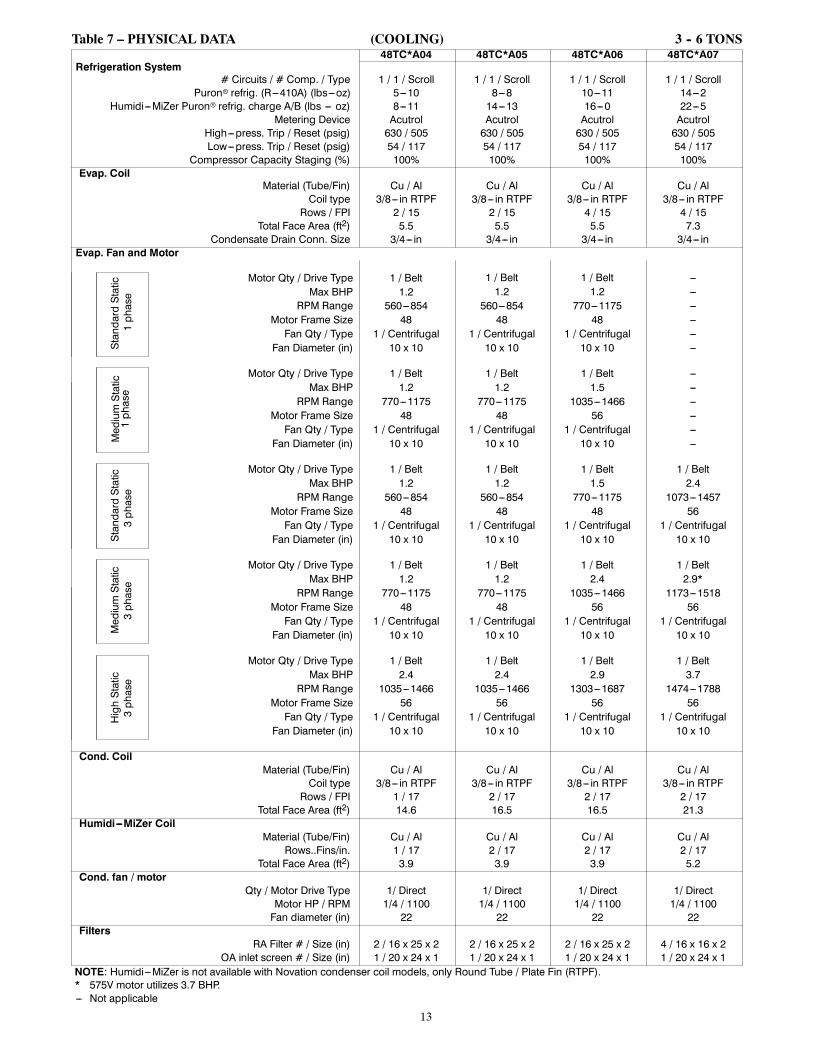
Fig. 8 -- Roof Curb Details 48TC 08--14

25
CURBS, WEIGHTS & DIMENSIONS (cont.)
UN
ITO
UTD
OO
R C
OIL
TY
PE
H
48TC
-D14
MC
HX
11 3
/8[2
89]
48TC
-D14
RTP
F15
7/8
[403
]R
TPF
- RO
UN
D T
UB
E, P
LATE
FIN
(CO
PP
ER
/ALU
M)
MC
HX
- N
OV
ATI
ON
(ALU
M/A
LUM
)
CO
NN
EC
TIO
N S
IZE
S
A1
3/8"
[35]
DIA
FIE
LD P
OW
ER
SU
PP
LY H
OLE
B2
1/2"
[64]
DIA
PO
WE
R S
UP
PLY
KN
OC
KO
UT
C1
3/4"
[51]
DIA
GA
UG
E A
CC
ES
S P
LUG
D7/
8" [2
2] D
IA F
IELD
CO
NTR
OL
WIR
ING
HO
LE
E3/
4"-1
4 N
PT
CO
ND
EN
SA
TE D
RA
IN
F3/
4"-1
4 N
PT
GA
S C
ON
NE
CTI
ON
G2"
[51]
DIA
PO
WE
R S
UP
PLY
KN
OC
K-O
UT
(004
) 3/4
" FP
TG
AS
1 5/
8" [4
1.3]
*
THR
U-T
HE
-BA
SE
CH
AR
TTH
ES
E H
OLE
S R
EQ
UIR
ED
FO
R U
SE
CR
BTM
PW
R00
2A01
,004
A01
THR
EA
DE
DC
ON
DU
IT S
IZE
WIR
EU
SE
RE
Q'D
HO
LES
IZE
S (M
AX
.)
W1/
2"A
CC
.7/
8" [2
2.2]
X1/
2"24
V7/
8" [2
2.2]
Y1
1/4"
(002
,004
)P
OW
ER
1 3/
4" [4
4.4]
Z *FO
R "T
HR
U-T
HE
-BA
SE
PA
N" F
AC
TOR
Y O
PTI
ON
, FI
TTIN
GS
FO
R O
NLY
X, Y
, & Z
AR
E P
RO
VID
ED
(002
) PR
OV
IDE
S 3
/4" F
PT
THR
U C
UR
B
FLA
NG
E &
FIT
TIN
G.
BA
CK
IND
OO
R C
OIL
AC
CE
SS
PA
NE
L
FILT
ER
AC
CE
SS
PA
NE
L(D
ISP
OS
AB
LE F
ILTE
RS
)
CO
ND
EN
SE
RC
OIL
NO
TES
:
1. D
IME
NS
ION
S A
RE
IN IN
CH
ES
, DIM
EN
SIO
NS
IN
[ ]
AR
E IN
MIL
LIM
ETE
RS
.
2.
3.
11 [279
]
14 [355
]
16 [412
]
18 [469
]
29-5
/8[7
51]
25-1
/2[6
46]
37-5
/8[9
55]
36-3
/8[9
25]
RE
TUR
N A
IR
12-5
/8[3
21]
40-3
/8[1
027]
6-1/
4[1
59]
20-3
/4[5
26]
40-3
/8[1
026]
3-1/
4[8
3]14 [3
56]
28-3
/4[7
31]
SU
PP
LYA
IR
4 [100
]
EC
ON
OM
IZE
R H
OO
D (O
PTI
ON
AL)
RE
TUR
NA
IR SU
PP
LYA
IR
E A
LT.
CO
ND
EN
SA
TED
RA
IN O
PE
NIN
G
SE
ETH
RU
-TH
E-B
AS
EC
HA
RT
W X Y -
28-3
/8[7
20]
SU
PP
LY A
IR
13-7
/8[3
53]
12-5
/8[3
21]
26 [649
]
5-3/
4[1
46]
6-3/
8[1
61]
7 [177
]
37-7
/8[9
63]
42 [106
6]
5-3/
4[1
46]
36-3
/8[9
25]
RE
TUR
NA
IR
RE
TUR
NA
IR
RIG
HT
OU
TSID
EA
IR
BA
RO
ME
TRIC
RE
LIE
FFL
OW
E S
TD.
CO
ND
EN
SA
TED
RA
INFI
LTE
R
FLU
EH
OO
D
2-7/
8[7
3]IN
BA
SE
PA
N
88-1
/8[2
238]
2-5/
8[6
7] TYP
CU
RB
WID
TH
37 [940
]
8-3/
8[2
14]
49-3
/8[1
253]
F
IND
OO
R B
LOW
ER
AC
CE
SS
FRO
NT
HA
ND
LEH
AN
DLE
OP
TIO
NA
LFA
CTO
RY
INS
TALL
ED
DIS
CO
NN
EC
T
CO
NTR
OL
BO
XA
CC
ES
S P
AN
EL
59-1
/2[1
510]
6-5/
8[1
68]
36 [913
]
3-3/
4[9
5]
CO
ND
EN
SE
RC
OIL
LEFT
DC
OP
TIO
NA
LFA
CTO
RY
INS
TALL
ED
CO
NV
EN
IEN
CE
OU
TLE
T
4-5/
8[1
18]
H A,
B,
G
ELE
CTR
ICA
LD
ISC
ON
NE
CT
LOC
ATI
ON
A10486
Fig. 9 -- Dimensions 48TC 14

26
CURBS, WEIGHTS & DIMENSIONS (cont.)
Z
FRONT
Y
X
CORNER ACORNER B
CORNER CCORNER D
TOP
48TC-D14RTPF - ROUND TUBE, PLATE FIN (COPPER/ALUM)MCHX - MICROCHANNEL (ALUM/ALUM)
OUTDOOR COIL TYPE
MCHXRTPF 1167 530 349 159 167 76 211 96 440 200 31 3/8 [797] 34 3/4 [883] 21 7/8 [556]
UNITSTD. UNIT WEIGHT***
CORNERWEIGHT (A)
CORNERWEIGHT (B)
CORNERWEIGHT (C)
CORNERWEIGHT (D) C.G.
LBS. KG. LBS. KG. LBS. KG. LBS. KG. LBS. KG. X Y Z48TC-D14 1116 506 297 135 157 71 229 104 434 197 29 1/2 [749] 34 1/4 [870] 20 1/4 [514]
A10487A
Fig. 10 -- Dimensions 48TC 14
C
BA
D
C08337
Fig. 11 -- Service Clearance
LOC DIMENSION CONDITION
A
48--- in (1219 mm) Unit disconnect is mounted on panel36--- in (914 mm) If dimension---B is 12--- in (305 mm)18--- in (457 mm) No disconnect, convenience outlet option18--- in (457 mm) Recommended service clearance (use electric screwdriver)12--- in (305 mm) Minimum clearance (use manual ratchet screwdriver)
B36--- in (914 mm) Unit has economizer12--- in (305 mm) If dimension---A is 36--- in (914 mm)Special Check for sources of flue products within 10--- ft of unit fresh air intake hood
C36--- in (914 mm) Side condensate drain is used18--- in (457 mm) Minimum clearance
D
48--- in (1219 mm) No flue discharge accessory installed, surface is combustible material42--- in (1067 mm) Surface behind servicer is grounded (e.g., metal, masonry wall, another unit)36--- in (914 mm) Surface behind servicer is electrically non---conductive (e.g., wood, fiberglass)Special Check for adjacent units or building fresh air intakes within 10--- ft of this unit’s flue outlet
NOTE: Unit not designed to have overhead obstruction. Contact Application Engineering for guidance on any application planning overheadobstruction or vertical clearances.
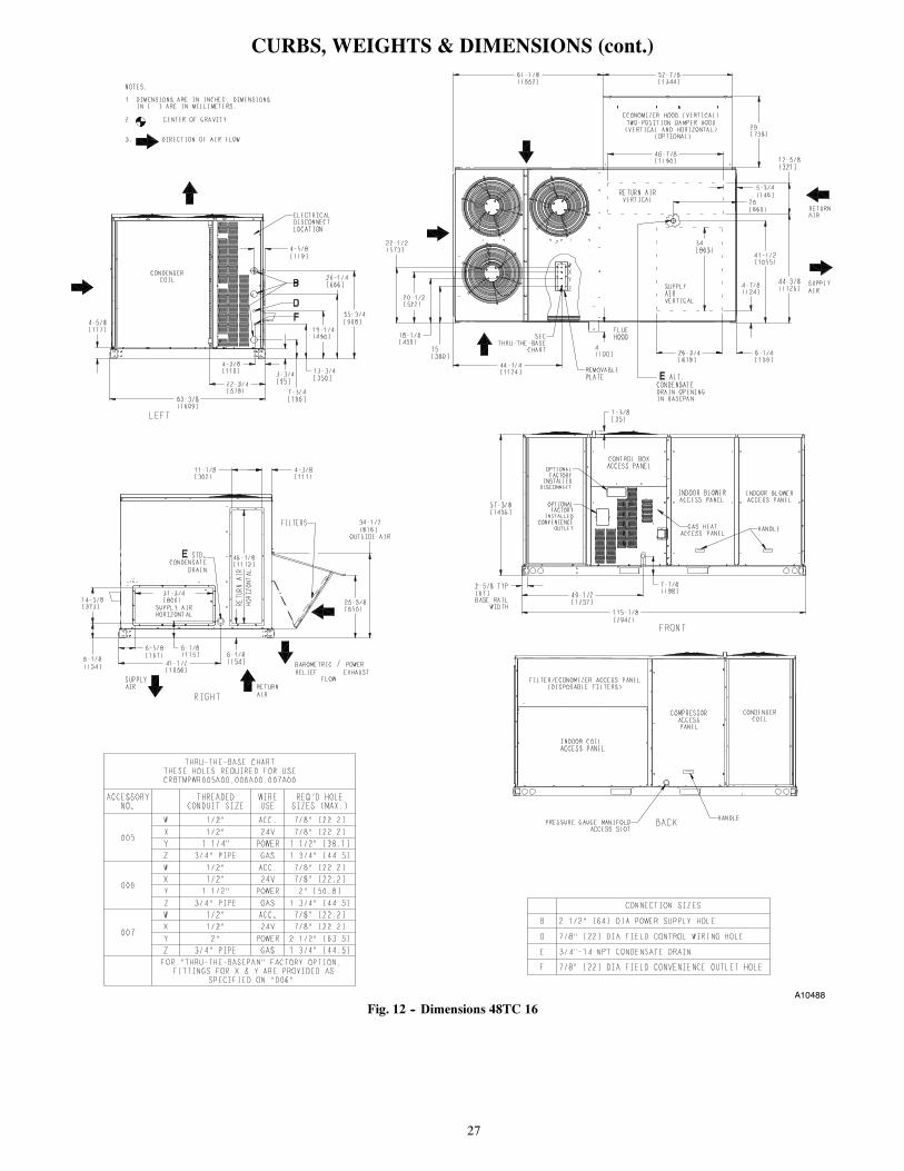
27
CURBS, WEIGHTS & DIMENSIONS (cont.)
A10488
Fig. 12 -- Dimensions 48TC 16

28
CURBS, WEIGHTS & DIMENSIONS (cont.)
C10862B
Fig. 13 -- Dimensions 48TC 16
C
BA
D
C10578B
Fig. 14 -- Service Clearance
LOC DIMENSION CONDITION
A
48--- in (1219 mm) Unit disconnect is mounted on panel18--- in (457 mm) No disconnect, convenience outlet option18--- in (457 mm) Recommended service clearance12--- in (305 mm) Minimum clearance
B42--- in (1067 mm) Surface behind servicer is grounded (e.g., metal, masonry wall)36--- in (914 mm) Surface behind servicer is electrically non---conductive (e.g., wood, fiberglass)Special Check for sources of flue products within 10--- ft of unit fresh air intake hood
C36--- in (914 mm) Side condensate drain is used18--- in (457 mm) Minimum clearance
D
48--- in (1219 mm) No flue discharge accessory installed, surface is combustible material42--- in (1067 mm) Surface behind servicer is grounded (e.g., metal, masonry wall, another unit)36--- in (914 mm) Surface behind servicer is electrically non---conductive (e.g., wood, fiberglass)Special Check for adjacent units or building fresh air intakes within 10--- ft of this unit’s flue outlet
NOTE: Unit not designed to have overhead obstruction. Contact Application Engineering for guidance on any application planning overheadobstruction or vertical clearances.

29
CURBS, WEIGHTS & DIMENSIONS (cont.)
C10772B
Fig. 15 -- Roof Curb Details 48TC 16
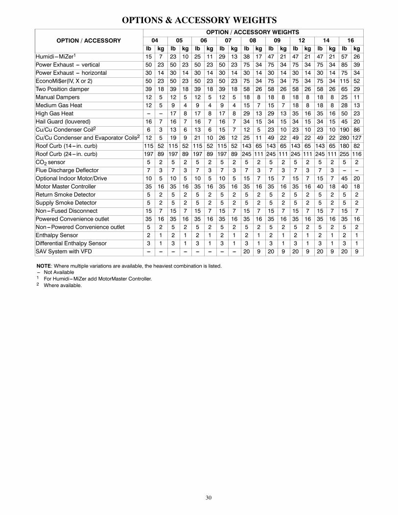
30
OPTIONS & ACCESSORY WEIGHTS
OPTION / ACCESSORYOPTION / ACCESSORY WEIGHTS
04 05 06 07 08 09 12 14 16lb kg lb kg lb kg lb kg lb kg lb kg lb kg lb kg lb kg
Humidi---MiZer1 15 7 23 10 25 11 29 13 38 17 47 21 47 21 47 21 57 26Power Exhaust --- vertical 50 23 50 23 50 23 50 23 75 34 75 34 75 34 75 34 85 39Power Exhaust --- horizontal 30 14 30 14 30 14 30 14 30 14 30 14 30 14 30 14 75 34EconoMi$er(IV, X or 2) 50 23 50 23 50 23 50 23 75 34 75 34 75 34 75 34 115 52Two Position damper 39 18 39 18 39 18 39 18 58 26 58 26 58 26 58 26 65 29Manual Dampers 12 5 12 5 12 5 12 5 18 8 18 8 18 8 18 8 25 11Medium Gas Heat 12 5 9 4 9 4 9 4 15 7 15 7 18 8 18 8 28 13High Gas Heat --- --- 17 8 17 8 17 8 29 13 29 13 35 16 35 16 50 23Hail Guard (louvered) 16 7 16 7 16 7 16 7 34 15 34 15 34 15 34 15 45 20Cu/Cu Condenser Coil2 6 3 13 6 13 6 15 7 12 5 23 10 23 10 23 10 190 86Cu/Cu Condenser and Evaporator Coils2 12 5 19 9 21 10 26 12 25 11 49 22 49 22 49 22 280 127Roof Curb (14--- in. curb) 115 52 115 52 115 52 115 52 143 65 143 65 143 65 143 65 180 82Roof Curb (24--- in. curb) 197 89 197 89 197 89 197 89 245 111 245 111 245 111 245 111 255 116CO2 sensor 5 2 5 2 5 2 5 2 5 2 5 2 5 2 5 2 5 2Flue Discharge Deflector 7 3 7 3 7 3 7 3 7 3 7 3 7 3 7 3 --- ---Optional Indoor Motor/Drive 10 5 10 5 10 5 10 5 15 7 15 7 15 7 15 7 45 20Motor Master Controller 35 16 35 16 35 16 35 16 35 16 35 16 35 16 40 18 40 18Return Smoke Detector 5 2 5 2 5 2 5 2 5 2 5 2 5 2 5 2 5 2Supply Smoke Detector 5 2 5 2 5 2 5 2 5 2 5 2 5 2 5 2 5 2Non---Fused Disconnect 15 7 15 7 15 7 15 7 15 7 15 7 15 7 15 7 15 7Powered Convenience outlet 35 16 35 16 35 16 35 16 35 16 35 16 35 16 35 16 35 16Non---Powered Convenience outlet 5 2 5 2 5 2 5 2 5 2 5 2 5 2 5 2 5 2Enthalpy Sensor 2 1 2 1 2 1 2 1 2 1 2 1 2 1 2 1 2 1Differential Enthalpy Sensor 3 1 3 1 3 1 3 1 3 1 3 1 3 1 3 1 3 1SAV System with VFD --- --- --- --- --- --- --- --- 20 9 20 9 20 9 20 9 20 9
NOTE: Where multiple variations are available, the heaviest combination is listed.--- Not Available1 For Humidi---MiZer add MotorMaster Controller.2 Where available.

31
APPLICATION DATAMin operating ambient temp (cooling):
In mechanical cooling mode, your Carrier rooftop unit cansafely operate down to an outdoor ambient temperature of40_F (4_C) and 25_F (--4_C), with an accessory winterstart kit. It is possible to provide cooling at lower outdoorambient temperatures by using less outside air,economizers, and/or accessory low ambient kits.
Max operating ambient temp (cooling):
The maximum operating ambient temperature for coolingmode is 115_F (46_C). While cooling operation above115_F (46_C) may be possible, it could cause either areduction in performance, reliability, or a protective actionby the unit’s internal safety devices.
Min mixed air temp (heating):
Using the factory settings, the minimum temperatures forthe mixed air (the combined temperature of the warmreturn air and the cold outdoor air) entering the dimpled,gas heat exchangers are:
Aluminized Stainless Steel50_F (10_C) continuous
45_F (7_C) intermittent
40_F (4_C) continuous
35_F (2_C) intermittent
Operating at lower mixed--air temperatures may bepossible, if a field supplied, outdoor air thermostatinitiates both heat stages when the temperature is less thanthe minimum temperatures listed above. Please contactyour local Carrier representative for assistance.
Min and max airflow (heating and cooling):
To maintain safe and reliable operation of your rooftop,operate within the heating airflow limits during heatingmode and cooling airflow limits during cooling mode.Operating above the max may cause blow--off, undesiredairflow noise, or airflow related problems with the rooftopunit. Operating below the min may cause problems withcoil freeze--up and unsafe heating operation. Heating andcooling limitations differ when evaluating operating cfm,the minimum value is the HIGHER of the cooling andheating minimum cfm values published in Table 6 and themaximum value is the LOWER of the cooling and heatingmaximum values published in Table 6.
Heating--to--cooling changeover:
Your unit will automatically change from heating tocooling mode when using a thermostat with anauto--changeover feature.
Airflow:
All units are draw--through in cooling mode andblow--through in heating mode.
Outdoor air application strategies:
Economizers reduce operating expenses and compressorrun time by providing a free source of cooling and ameans of ventilation to match application changing needs.In fact, they should be considered for most applications.Also, consider the various economizer control methodsand their benefits, as well as sensors required toaccomplish your application goals. Please contact yourlocal Carrier representative for assistance.
Motor limits, Brake horsepower (BHP):
Due to internal design of Carrier units, the air path, andspecially designed motors, the full horsepower (maximumcontinuous BHP) band, as listed in Table 8 and 10, can beused with the utmost confidence. There is no need forextra safety factors, as Carrier motors are designed andrigorously tested to use the entire, listed BHP rangewithout either nuisance tripping or premature motorfailure.
Propane heating:
Propane has different physical qualities than natural gas.As a result, propane requires different fuel to air mixture.To optimize the fuel/air mixture for propane, Carrier sellsdifferent burner orifices in an easy to install accessory kit.To select the correct burner orifices or determine the heatcapacity for a propane application, use either the selectionsoftware, or the unit’s service manual.
High altitude heating:
High altitudes have less oxygen, which affects the fuel/airmixture in heat exchangers. In order to maintain a properfuel/air mixture, heat exchangers operating in altitudesabove 2000 ft (610 m) require different orifices. To selectthe correct burner orifices or determine the heat capacityfor a high altitude application, use either the selectionsoftware, or the unit’s service manual.
High altitudes have less oxygen, which means heatexchangers need less fuel. The new gas orifices in thisfield installed kit make the necessary adjustment for highaltitude applications. They restore the optimal fuel to airmixture and maintain healthy combustion on altitudesabove 2000 ft (610 m).
NOTE: Typical natural gas heating value ranges from975 to 1050 Btu/ft3 at sea level nationally. The heatingvalue goes down approximately 1.7% per every thousandfeet elevation. Standard factory orifices can typically beused up to 2000 ft (610m) elevation without anyoperational issues.
NOTE: For installations in Canada, the input ratingshould be derated by 10% for altitudes from 2000 ft(610m) to 4500 ft (1372m) above sea level.

32
APPLICATION DATA (cont.)Sizing a rooftop
Bigger isn’t necessarily better. While an air conditionerneeds to have enough capacity to meet the design loads, itdoesn’t need excess capacity. In fact, excess capacitytypically results in very poor part load performance andhumidity control.
Using higher design temperatures than ASHRAErecommends for your location, adding “safety factors” tothe calculated load, are all signs of oversizing airconditioners. Oversizing the air conditioner leads to poorhumidity control, reduced efficiency, higher utility bills,larger indoor temperature swings, excessive noise, andincreased wear and tear on the air conditioner.
Rather than oversizing an air conditioner, engineersshould “right size” or even slightly undersize airconditioners. Correctly sizing an air conditioner controlshumidity better; promotes efficiency; reduces utility bills;extends equipment life, and maintains even, comfortabletemperatures. Please contact your local Carrierrepresentative for assistance.
Low ambient applications
The optional Carrier economizer can adequately cool yourspace by bringing in fresh, cool outside air. In fact, whenso equipped, accessory low ambient kit may not benecessary. In low ambient conditions, unless the outdoorair is excessively humid or contaminated, economizerbased “free cooling” is the preferred less costly andenergy conscious method.
In low ambient applications where outside air might notbe desired (such as contaminated or excessively humidoutdoor environments), your Carrier rooftop can operateat ambient temperatures down to --20_F (--29_C) using therecommended accessory Motormaster low ambientcontroller.
Staged Air Volume (SAV) with VariableFrequency Drive (VFD)
Carrier’s Staged Air Volume (SAV) system utilizes aVariable Frequency Drive (VFD) to automatically adjustthe indoor fan motor speed in sequence with the unitscooling operation. Per ASHRAE 90.1 2010 standardsection 6.4.3.10.b, during the first stage of coolingoperation the VFD will adjust the fan motor to provide2/3rd of the total cfm established for the unit. When a callfor the second stage of cooling is required, the VFD willallow the total cfm for the unit established (100%).During the heating mode, the VFD will allow total designcfm (100%) operation and during the ventilation mode theVFD will allow operation to 2/3rd of total cfm.
The VFD used in Carrier’s SAV system has soft startcapabilities to slowly ramp up the speeds, thus eliminatingany high inrush air volume during initial start--up. It alsohas internal over current protection for the fan motor anda field installed display kit that allows adjustment and indepth diagnostics of the VFD.
This SAV system is available on models with 2--stagecooling operation with electrical mechanical or RTU Open(multi Protocol) controls. Both space sensor andconventional thermostats/controls can be used to provideaccurate control in any application.
The SAV system is very flexible for initial fanperformance set up and adjustment. The standard factoryshipped VFD is pre programmed to automatically stagethe fan speed between the first and second stage ofcooling. The unit fan performance static pressure and cfmcan be easily adjusted using the traditional means ofpulley adjustments. The other means to adjust the unitstatic and cfm performance is to utilize the field installeddisplay module and adjust the frequency and voltage inthe VFD to required performance requirements. In eithercase, once set up the VFD will automatically adjust thespeed between the cooling stage operation.

33
SELECTION PROCEDURE (WITH 48TC*A07 EXAMPLE)1
I. Determine cooling and heating loads.
Given:Mixed air dry bulb 80_F (27_C)Mixed air wet bulb 67_F (19_C)Ambient dry bulb 95_F (35_C)TCLoad 72.0 MBHSHCLoad 54.0 MBHVertical supply air 2100 CFMHeating load 85.0 MBHExternal static pressure 0.67 in. wgElectrical characteristics 230--3--60
II. Make an initial guess at cooling tons.
Refrig. tons = TCLoad / 12 MBH per tonRefrig. tons = 72.0 / 12 = 6.0 tonsIn this case, start by looking at the 48TC**07.
III. Look up the rooftop’s TC and SHC.
Table 19 shows that, at the application’s supply airCFM, mixed air and ambient temperatures, the48TC*A07 supplies:TC = 73.7 MBH2
SHC = 54.4 MBH2
IV. Calculate the building latent heat load.
LCLoad = TCLoad -- SHCLoadLCLoad = 72.0 MBH -- 54.0 MBH = 18.0 MBH
V. Calculate RTU latent heat capacity.
LC = TC -- SHCLC = 73.7 MBH -- 54.4 MBH = 19.3 MBH
VI. Compare RTU capacities to loads.3
Compare the rooftop’s SHC and LC to thebuilding’s sensible and latent heat loads.
VII. Select factory options (FIOP)
Local code requires an economizer for any unit withTC greater than 65.0 MBH.
VIII.Calculate the total static pressure.External static pressure 0.67 in. wgSum of FIOP / Accessory static +0.13 in. wg
Total Static Pressure 0.80 in. wg
IX. Look up the indoor fan RPM & BHP.
Table 47 shows, at 2100 CFM & ESP= 0.8,RPM = 1358 & BHP = 1.52
X. Convert BHP (Step VIII) into fan motor heat.
Fan motor heat = 2.546* BHP/Motor Eff.4
Fan motor heat = 4.9 MBH
XI. Calculate RTU heating capacity.
Building heating load 85.0 MBHFan motor heat --4.9 MBH
Required heating capacity 80.1 MBH
XII. Select a gas heater.
Table 3 shows the heating capacities of the48TCEA07 = 93.0 MBH. Select the 48TCEA07
XIII.Determine electrical requirements.
The MCA and MOCP tables show 48TC*A07(without convenience outlet) as:MCA = 30.5 amps & MOCP = 45.0 ampsMin. disconnect size: FLA = 30 & LRA = 157.
LegendBHP — Brake horsepowerFLA — Full load ampsLC — Latent capacityLRA — Lock rotor ampMBH — (1,000) BTUHMCA — Min. circuit ampacityMOCP — Max. over---current protectionRPM — Revolutions per minuteRTU — Rooftop unitSHC — Sensible heat capacityTC — Total capacity
NOTES:1. Selection software by Carrier saves time by performing manyof the steps above. Contact your Carrier sales representativefor assistance.
2. Unit ratings are gross capacities and do not include the effectof evaporator fan motor heat. See Step X. for determiningamount of evaporator fan motor heat to subtract from totaland sensible capacities to obtain net cooling and net sens-ible capacities.
3. Selecting a unit with a SHC slightly lower than the SHCLoad isoften better than oversizing. Slightly lower SHC’s will helpcontrol indoor humidity, and prevent temperature swings.
4. Indoor fan motor efficiency is available in Table 83. Use thedecimal form in the equation, eg. 80% = .8.
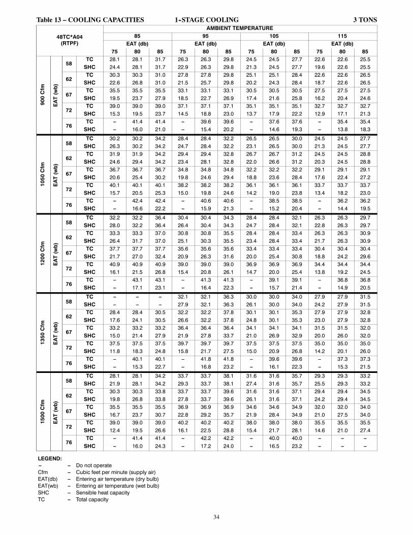
34
Table 13 – COOLING CAPACITIES 1--STAGE COOLING 3 TONS
48TC*A04(RTPF)
AMBIENT TEMPERATURE85 95 105 115
EAT (db) EAT (db) EAT (db) EAT (db)75 80 85 75 80 85 75 80 85 75 80 85
900Cfm
EAT(wb)
58TC 28.1 28.1 31.7 26.3 26.3 29.8 24.5 24.5 27.7 22.6 22.6 25.5SHC 24.4 28.1 31.7 22.9 26.3 29.8 21.3 24.5 27.7 19.6 22.6 25.5
62TC 30.3 30.3 31.0 27.8 27.8 29.8 25.1 25.1 28.4 22.6 22.6 26.5SHC 22.6 26.8 31.0 21.5 25.7 29.8 20.2 24.3 28.4 18.7 22.6 26.5
67TC 35.5 35.5 35.5 33.1 33.1 33.1 30.5 30.5 30.5 27.5 27.5 27.5SHC 19.5 23.7 27.9 18.5 22.7 26.9 17.4 21.6 25.8 16.2 20.4 24.6
72TC 39.0 39.0 39.0 37.1 37.1 37.1 35.1 35.1 35.1 32.7 32.7 32.7SHC 15.3 19.5 23.7 14.5 18.8 23.0 13.7 17.9 22.2 12.9 17.1 21.3
76TC --- 41.4 41.4 --- 39.6 39.6 --- 37.6 37.6 --- 35.4 35.4SHC --- 16.0 21.0 --- 15.4 20.2 --- 14.6 19.3 --- 13.8 18.3
1050Cfm
EAT(wb)
58TC 30.2 30.2 34.2 28.4 28.4 32.2 26.5 26.5 30.0 24.5 24.5 27.7SHC 26.3 30.2 34.2 24.7 28.4 32.2 23.1 26.5 30.0 21.3 24.5 27.7
62TC 31.9 31.9 34.2 29.4 29.4 32.8 26.7 26.7 31.2 24.5 24.5 28.8SHC 24.6 29.4 34.2 23.4 28.1 32.8 22.0 26.6 31.2 20.3 24.5 28.8
67TC 36.7 36.7 36.7 34.8 34.8 34.8 32.2 32.2 32.2 29.1 29.1 29.1SHC 20.6 25.4 30.2 19.8 24.6 29.4 18.8 23.6 28.4 17.6 22.4 27.2
72TC 40.1 40.1 40.1 38.2 38.2 38.2 36.1 36.1 36.1 33.7 33.7 33.7SHC 15.7 20.5 25.3 15.0 19.8 24.6 14.2 19.0 23.8 13.4 18.2 23.0
76TC --- 42.4 42.4 --- 40.6 40.6 --- 38.5 38.5 --- 36.2 36.2SHC --- 16.6 22.2 --- 15.9 21.3 --- 15.2 20.4 --- 14.4 19.5
1200Cfm
EAT(wb)
58TC 32.2 32.2 36.4 30.4 30.4 34.3 28.4 28.4 32.1 26.3 26.3 29.7SHC 28.0 32.2 36.4 26.4 30.4 34.3 24.7 28.4 32.1 22.8 26.3 29.7
62TC 33.3 33.3 37.0 30.8 30.8 35.5 28.4 28.4 33.4 26.3 26.3 30.9SHC 26.4 31.7 37.0 25.1 30.3 35.5 23.4 28.4 33.4 21.7 26.3 30.9
67TC 37.7 37.7 37.7 35.6 35.6 35.6 33.4 33.4 33.4 30.4 30.4 30.4SHC 21.7 27.0 32.4 20.9 26.3 31.6 20.0 25.4 30.8 18.8 24.2 29.6
72TC 40.9 40.9 40.9 39.0 39.0 39.0 36.9 36.9 36.9 34.4 34.4 34.4SHC 16.1 21.5 26.8 15.4 20.8 26.1 14.7 20.0 25.4 13.8 19.2 24.5
76TC --- 43.1 43.1 --- 41.3 41.3 --- 39.1 39.1 --- 36.8 36.8SHC --- 17.1 23.1 --- 16.4 22.3 --- 15.7 21.4 --- 14.9 20.5
1350Cfm
EAT(wb)
58TC --- --- --- 32.1 32.1 36.3 30.0 30.0 34.0 27.9 27.9 31.5SHC --- --- --- 27.9 32.1 36.3 26.1 30.0 34.0 24.2 27.9 31.5
62TC 28.4 28.4 30.5 32.2 32.2 37.8 30.1 30.1 35.3 27.9 27.9 32.8SHC 17.6 24.1 30.5 26.6 32.2 37.8 24.8 30.1 35.3 23.0 27.9 32.8
67TC 33.2 33.2 33.2 36.4 36.4 36.4 34.1 34.1 34.1 31.5 31.5 32.0SHC 15.0 21.4 27.9 21.9 27.8 33.7 21.0 26.9 32.9 20.0 26.0 32.0
72TC 37.5 37.5 37.5 39.7 39.7 39.7 37.5 37.5 37.5 35.0 35.0 35.0SHC 11.8 18.3 24.8 15.8 21.7 27.5 15.0 20.9 26.8 14.2 20.1 26.0
76TC --- 40.1 40.1 --- 41.8 41.8 --- 39.6 39.6 --- 37.3 37.3SHC --- 15.3 22.7 --- 16.8 23.2 --- 16.1 22.3 --- 15.3 21.5
1500Cfm
EAT(wb)
58TC 28.1 28.1 34.2 33.7 33.7 38.1 31.6 31.6 35.7 29.3 29.3 33.2SHC 21.9 28.1 34.2 29.3 33.7 38.1 27.4 31.6 35.7 25.5 29.3 33.2
62TC 30.3 30.3 33.8 33.7 33.7 39.6 31.6 31.6 37.1 29.4 29.4 34.5SHC 19.8 26.8 33.8 27.8 33.7 39.6 26.1 31.6 37.1 24.2 29.4 34.5
67TC 35.5 35.5 35.5 36.9 36.9 36.9 34.6 34.6 34.9 32.0 32.0 34.0SHC 16.7 23.7 30.7 22.8 29.2 35.7 21.9 28.4 34.9 21.0 27.5 34.0
72TC 39.0 39.0 39.0 40.2 40.2 40.2 38.0 38.0 38.0 35.5 35.5 35.5SHC 12.4 19.5 26.6 16.1 22.5 28.8 15.4 21.7 28.1 14.6 21.0 27.4
76TC --- 41.4 41.4 --- 42.2 42.2 --- 40.0 40.0 --- --- ---SHC --- 16.0 24.3 --- 17.2 24.0 --- 16.5 23.2 --- --- ---
LEGEND:--- --- Do not operateCfm --- Cubic feet per minute (supply air)EAT(db) --- Entering air temperature (dry bulb)EAT(wb) --- Entering air temperature (wet bulb)SHC --- Sensible heat capacityTC --- Total capacity

35
Table 14 – COOLING CAPACITIES 1--STAGE COOLING 3 TONS
48TC04 (3 TONS) --- UNIT WITH HUMIDI---MIZER SYSTEM IN SUBCOOLING MODEAir Entering Evaporator --- CFM
Temp (F) Air EntCondenser (Edb)
80 dry bulb 80 dry bulb 80 dry bulb72 wet bulb 67 wet bulb 62 wet bulb
900 1200 1500 900 1200 1500 900 1200 1500
75TC 40.6 43.2 45.3 37.0 39.4 41.3 33.4 35.6 37.4SHC 21.6 23.9 25.6 25.6 27.7 29.3 29.6 31.6 33.1kW 2.0 2.0 2.0 2.0 2.0 2.0 2.0 2.0 2.0
85TC 37.0 39.6 41.7 33.6 36.0 37.9 30.2 32.3 34.1SHC 17.7 20.2 22.2 22.7 25.0 26.9 27.7 29.9 31.6kW 2.3 2.3 2.3 2.3 2.3 2.3 2.3 2.3 2.3
95TC 33.5 36.0 38.1 30.2 32.5 34.4 26.9 29.1 30.8SHC 13.7 16.6 18.8 19.7 22.4 24.4 25.7 28.2 30.1kW 2.6 2.6 2.6 2.5 2.5 2.5 2.5 2.5 2.5
105TC 29.9 32.4 34.5 26.8 29.1 31.0 23.6 25.8 27.5SHC 9.8 12.9 15.3 16.8 19.7 22.0 23.8 26.5 28.6kW 2.9 2.9 2.9 2.8 2.8 2.8 2.8 2.8 2.8
115TC 26.3 28.8 30.9 23.3 25.7 27.5 20.4 22.5 24.2SHC 5.8 9.2 11.9 13.8 17.0 19.5 21.9 24.8 27.1kW 3.2 3.2 3.2 3.1 3.1 3.1 3.1 3.1 3.1
48TC04 (3 TONS) --- UNIT WITH HUMIDI---MIZER SYSTEM IN HOT GAS REHEAT MODEAir Entering Evaporator --- CFM
Temp (F) Air EntCondenser (Edb)
75 dry bulb 75 dry bulb 75 dry bulb62.5 wet bulb (50% relative) 64 wet bulb (55% relative) 65.3 wet bulb (60% relative)1050 1200 1350 1050 1200 1350 1050 1200 1350
80TC 14.7 15.5 16.2 15.9 16.7 17.4 16.9 17.7 18.4SHC 6.7 7.6 8.5 4.8 5.7 6.6 3.2 4.1 5.0kW 2.0 2.0 2.0 2.0 2.0 2.0 2.0 2.0 2.0
75TC 15.1 15.8 16.4 16.2 17.0 17.6 17.2 18.0 18.6SHC 7.5 8.4 9.2 5.8 6.7 7.5 4.4 5.2 6.0kW 1.9 1.9 1.9 2.0 2.0 2.0 2.0 2.0 2.0
70TC 15.5 16.1 16.7 16.6 17.3 17.9 17.5 18.2 18.8SHC 8.4 9.3 10.0 6.9 7.7 8.5 5.5 6.4 7.1kW 1.9 1.9 1.9 1.9 1.9 1.9 1.9 1.9 1.9
60TC 16.2 16.8 17.3 17.2 17.8 18.3 18.1 18.7 19.2SHC 10.2 10.9 11.6 8.9 9.7 10.4 7.8 8.6 9.3kW 1.8 1.8 1.8 1.8 1.8 1.8 1.9 1.9 1.9
50TC 17.0 17.5 17.9 17.9 18.4 18.8 18.7 19.2 19.6SHC 11.9 12.6 13.2 11.0 11.6 12.2 10.1 10.8 11.4kW 1.7 1.7 1.7 1.8 1.8 1.8 1.8 1.8 1.8
40TC 17.7 18.1 18.5 18.6 19.0 19.3 19.3 19.7 20.1SHC 13.7 14.3 14.8 13.0 13.6 14.1 12.4 13.0 13.5kW 1.7 1.7 1.7 1.7 1.7 1.7 1.7 1.7 1.7
LEGENDEdb --- Entering Dry---BulbEwb --- Entering Wet---BulbkW --- Compressor Motor Power InputIdb --- Leaving Dry---BulbIwb --- Leaving Wet---BulbSHC --- Sensible Heat Capacity (1000 Btuh) GrossTC --- Total Capacity (1000 Btuh) Gross
NOTES:1. Direct interpolation is permissible. Do not extrapolate.2. The following formulas may be used:
tldb = tedb –sensible capacity (Btuh)
1.10 x cfmtlwb = Wet---bulb temperature corresponding to enthalpy of airleaving evaporator coil (hlwb)
hlwb = hewb –total capacity (Btuh)
4.5 x cfmWhere: hewb = Enthalpy of air entering evaporator coil

36
Table 15 – COOLING CAPACITIES 1--STAGE COOLING 4 TONS
48TC*A05(RTPF)
AMBIENT TEMPERATURE85 95 105 115
EAT (db) EAT (db) EAT (db) EAT (db)75 80 85 75 80 85 75 80 85 75 80 85
1200Cfm
EAT(wb)
58TC --- --- --- --- --- --- 36.1 36.1 40.7 34.3 34.3 38.6SHC --- --- --- --- --- --- 31.5 36.1 40.7 29.9 34.3 38.6
62TC 43.1 43.1 43.1 40.8 40.8 40.8 38.4 38.4 39.4 35.9 35.9 38.2SHC 31.2 36.4 41.7 30.1 35.3 40.6 28.9 34.1 39.4 27.8 33.0 38.2
67TC 47.4 47.4 47.4 45.2 45.2 45.2 42.9 42.9 42.9 40.3 40.3 40.3SHC 25.9 31.2 36.4 25.0 30.2 35.5 23.9 29.2 34.4 22.9 28.2 33.4
72TC 51.1 51.1 51.1 49.1 49.1 49.1 46.8 46.8 46.8 43.9 43.9 43.9SHC 20.1 25.5 30.9 19.4 24.7 30.1 18.4 23.7 29.0 17.4 22.7 28.0
76TC --- 53.3 53.3 --- 51.5 51.5 --- 49.2 49.2 --- 45.9 45.9SHC --- 20.8 27.4 --- 20.2 26.8 --- 19.3 25.7 --- 18.3 24.6
1400cfm
EAT(wb)
58TC 41.9 41.9 47.3 40.1 40.1 45.3 38.2 38.2 43.2 36.3 36.3 41.0SHC 36.6 41.9 47.3 35.0 40.1 45.3 33.3 38.2 43.2 31.7 36.3 41.0
62TC 44.6 44.6 45.4 42.3 42.3 44.2 39.8 39.8 42.9 37.3 37.3 41.6SHC 33.4 39.4 45.4 32.3 38.3 44.2 31.0 37.0 42.9 29.8 35.7 41.6
67TC 48.7 48.7 48.7 46.6 46.6 46.6 44.2 44.2 44.2 41.4 41.4 41.4SHC 27.3 33.2 39.2 26.4 32.3 38.3 25.3 31.3 37.3 24.2 30.2 36.2
72TC 52.2 52.2 52.2 50.3 50.3 50.3 47.8 47.8 47.8 44.8 44.8 44.8SHC 20.6 26.7 32.7 19.9 25.9 32.0 18.9 24.9 30.9 17.9 23.8 29.7
76TC --- 54.1 54.1 --- 52.3 52.3 --- 49.9 49.9 --- 46.4 46.4SHC --- 21.5 29.0 --- 20.8 28.0 --- 19.9 26.9 --- 18.8 25.7
1600Cfm
EAT(wb)
58TC 44.0 44.0 49.6 42.1 42.1 47.4 40.1 40.1 45.2 38.1 38.1 43.0SHC 38.3 44.0 49.6 36.7 42.1 47.4 34.9 40.1 45.2 33.2 38.1 43.0
62TC 45.7 45.7 48.6 43.5 43.5 47.5 41.0 41.0 46.0 38.5 38.5 44.4SHC 35.3 42.0 48.6 34.2 40.8 47.5 32.9 39.4 46.0 31.6 38.0 44.4
67TC 49.8 49.8 49.8 47.6 47.6 47.6 45.1 45.1 45.1 42.3 42.3 42.3SHC 28.4 35.0 41.6 27.6 34.2 40.9 26.5 33.2 39.9 25.4 32.1 38.7
72TC 53.0 53.0 53.0 51.1 51.1 51.1 48.6 48.6 48.6 45.4 45.4 45.4SHC 21.0 27.6 34.3 20.3 27.0 33.6 19.4 26.0 32.6 18.3 24.8 31.3
76TC --- 54.6 54.6 --- 52.8 52.8 --- 50.4 50.4 --- 46.8 46.8SHC --- 22.0 29.9 --- 21.3 29.0 --- 20.3 27.9 --- 19.2 26.6
1800Cfm
EAT(wb)
58TC 44.0 44.0 50.3 42.1 42.1 48.1 40.1 40.1 45.9 38.0 38.0 43.5SHC 37.6 44.0 50.3 36.0 42.1 48.1 34.3 40.1 45.9 32.6 38.0 43.5
62TC 45.7 45.7 49.5 43.5 43.5 48.3 41.0 41.0 46.8 38.4 38.4 45.2SHC 34.5 42.0 49.5 33.4 40.8 48.3 32.1 39.4 46.8 30.8 38.0 45.2
67TC 49.8 49.8 49.8 47.6 47.6 47.6 45.1 45.1 45.1 42.3 42.3 42.3SHC 27.6 35.0 42.5 26.8 34.2 41.7 25.7 33.2 40.7 24.6 32.1 39.5
72TC 53.0 53.0 53.0 51.1 51.1 51.1 48.6 48.6 48.6 45.4 45.4 45.4SHC 20.2 27.6 35.1 19.5 27.0 34.4 18.5 26.0 33.4 17.5 24.8 32.1
76TC --- 54.6 54.6 --- 52.8 52.8 --- 50.4 50.4 --- 46.8 46.8SHC --- 22.0 30.9 --- 21.3 30.0 --- 20.3 28.9 --- 19.2 27.5
2000Cfm
EAT(wb)
58TC 46.9 46.9 52.9 45.0 45.0 50.8 42.9 42.9 48.4 40.7 40.7 45.9SHC 40.9 46.9 52.9 39.3 45.0 50.8 37.4 42.9 48.4 35.5 40.7 45.9
62TC 47.5 47.5 54.0 45.3 45.3 52.5 43.0 43.0 50.3 40.7 40.7 47.7SHC 38.5 46.3 54.0 37.3 44.9 52.5 35.6 43.0 50.3 33.8 40.7 47.7
67TC 51.2 51.2 51.2 49.1 49.1 49.1 46.5 46.5 46.5 43.5 43.5 43.5SHC 30.5 38.3 46.0 29.8 37.6 45.5 28.7 36.6 44.5 27.5 35.4 43.2
72TC 54.0 54.0 54.0 52.1 52.1 52.1 49.7 49.7 49.7 46.2 46.2 46.2SHC 21.7 29.2 36.8 21.1 28.7 36.4 20.1 27.8 35.4 18.9 26.4 33.9
76TC --- 55.2 55.2 --- 53.5 53.5 --- 51.0 51.0 --- 47.3 47.3SHC --- 22.7 31.4 --- 22.0 30.6 --- 21.1 29.6 --- 19.9 28.1
LEGEND:--- --- Do not operateCfm --- Cubic feet per minute (supply air)EAT(db) --- Entering air temperature (dry bulb)EAT(wb) --- Entering air temperature (wet bulb)SHC --- Sensible heat capacityTC --- Total capacity

37
Table 16 – COOLING CAPACITIES 1--STAGE COOLING 4 TONS
48TC05 (4 TONS) --- UNIT WITH HUMIDI---MIZER SYSTEM IN SUBCOOLING MODEAir Entering Evaporator --- CFM
Temp (F) Air EntCondenser (Edb)
80 dry bulb 80 dry bulb 80 dry bulb72 wet bulb 67 wet bulb 62 wet bulb
1200 1600 2000 1200 1600 2000 1200 1600 2000
75TC 52.5 55.9 58.6 47.1 50.2 52.7 41.7 44.5 46.8SHC 22.6 25.5 27.8 27.1 29.9 32.0 31.6 34.2 36.2kW 2.5 2.5 2.5 2.5 2.5 2.5 2.5 2.5 2.5
85TC 48.7 52.2 54.9 43.4 46.5 49.0 38.0 40.8 43.1SHC 18.0 21.3 23.9 23.6 26.8 29.2 29.3 32.2 34.4kW 2.9 2.9 2.9 2.9 2.9 2.9 2.9 2.9 2.9
95TC 44.9 48.4 51.2 39.6 42.8 45.3 34.3 37.1 39.4SHC 13.4 17.2 20.0 20.2 23.7 26.4 27.0 30.2 32.7kW 3.4 3.4 3.4 3.3 3.3 3.3 3.3 3.3 3.3
105TC 41.1 44.7 47.5 35.9 39.1 41.7 30.6 33.5 35.8SHC 8.8 13.0 16.1 16.7 20.6 23.6 24.6 28.2 31.0kW 3.8 3.8 3.8 3.7 3.7 3.7 3.7 3.7 3.7
115TC 37.4 41.0 43.9 32.1 35.4 38.0 26.8 29.8 32.1SHC 4.3 8.8 12.2 13.3 17.5 20.7 22.3 26.2 29.2kW 4.2 4.2 4.2 4.2 4.2 4.2 4.1 4.1 4.1
48TC05 (4 TONS) --- UNIT WITH HUMIDI---MIZER SYSTEM IN HOT GAS REHEAT MODEAir Entering Evaporator --- CFM
Temp (F) Air EntCondenser (Edb)
75 dry bulb 75 dry bulb 75 dry bulb62.5 wet bulb (50% relative) 64 wet bulb (55% relative) 65.3 wet bulb (60% relative)1200 1600 2000 1200 1600 2000 1200 1600 2000
80TC 11.6 13.8 15.5 13.5 15.8 17.6 15.2 17.5 19.3SHC ---1.0 1.2 3.0 ---3.1 ---0.8 0.9 ---4.8 ---2.6 ---0.9kW 2.5 2.5 2.5 2.5 2.5 2.5 2.5 2.5 2.5
75TC 12.5 14.6 16.2 14.3 16.4 18.1 15.9 18.1 19.8SHC ---0.7 1.4 3.0 ---2.7 ---0.6 1.1 ---4.3 ---2.2 ---0.6kW 2.5 2.5 2.5 2.5 2.5 2.5 2.5 2.5 2.5
70TC 13.4 15.3 16.8 15.1 17.1 18.7 16.6 18.7 20.3SHC ---0.5 1.5 3.0 ---2.3 ---0.3 1.2 ---3.8 ---1.9 ---0.3kW 2.5 2.5 2.5 2.5 2.5 2.5 2.5 2.5 2.5
60TC 15.1 16.8 18.1 16.7 18.4 19.8 18.1 19.9 21.2SHC 0.0 1.7 3.1 ---1.5 0.2 1.5 ---2.8 ---1.1 0.2kW 2.6 2.6 2.6 2.6 2.6 2.6 2.6 2.6 2.6
50TC 16.9 18.3 19.4 18.3 19.8 20.9 19.6 21.0 22.2SHC 0.6 2.0 3.1 ---0.7 0.7 1.8 ---1.8 ---0.4 0.7kW 2.6 2.6 2.6 2.6 2.6 2.6 2.6 2.6 2.6
40TC 18.7 19.8 20.7 19.9 21.1 22.0 21.0 22.2 23.2SHC 1.1 2.2 3.1 0.1 1.2 2.1 ---0.8 0.4 1.3kW 2.6 2.6 2.6 2.7 2.7 2.7 2.7 2.7 2.7
LEGENDEdb --- Entering Dry---BulbEwb --- Entering Wet---BulbkW --- Compressor Motor Power InputIdb --- Leaving Dry---BulbIwb --- Leaving Wet---BulbSHC --- Sensible Heat Capacity (1000 Btuh) GrossTC --- Total Capacity (1000 Btuh) Gross
NOTES:1. Direct interpolation is permissible. Do not extrapolate.2. The following formulas may be used:
tldb = tedb –sensible capacity (Btuh)
1.10 x cfmtlwb = Wet---bulb temperature corresponding to enthalpy of airleaving evaporator coil (hlwb)
hlwb = hewb –total capacity (Btuh)
4.5 x cfmWhere: hewb = Enthalpy of air entering evaporator coil

38
Table 17 – COOLING CAPACITIES 1--STAGE COOLING 5 TONS
48TC*A06(RTPF)
AMBIENT TEMPERATURE85 95 105 115
EAT (db) EAT (db) EAT (db) EAT (db)75 80 85 75 80 85 75 80 85 75 80 85
1500Cfm
EAT(wb)
58TC 52.9 52.9 60.0 49.9 49.9 56.6 46.6 46.6 52.9 43.1 43.1 48.9SHC 45.8 52.9 60.0 43.2 49.9 56.6 40.4 46.6 52.9 37.3 43.1 48.9
62TC 56.2 56.2 57.6 52.2 52.2 55.7 47.8 47.8 53.5 43.2 43.2 51.0SHC 41.8 49.7 57.6 39.9 47.8 55.7 37.8 45.6 53.5 35.5 43.2 51.0
67TC 62.4 62.4 62.4 58.8 58.8 58.8 54.4 54.4 54.4 49.5 49.5 49.5SHC 34.8 42.8 50.7 33.2 41.2 49.1 31.4 39.3 47.3 29.4 37.3 45.3
72TC 68.2 68.2 68.2 64.8 64.8 64.8 60.8 60.8 60.8 56.2 56.2 56.2SHC 27.2 35.2 43.2 25.9 33.9 41.9 24.4 32.4 40.4 22.6 30.6 38.6
76TC --- 71.1 71.1 --- 69.0 69.0 --- 65.4 65.4 --- 60.9 60.9SHC --- 28.4 36.6 --- 27.6 35.9 --- 26.3 34.6 --- 24.8 33.0
1750Cfm
EAT(wb)
58TC 56.5 56.5 64.0 53.3 53.3 60.4 49.8 49.8 56.5 46.1 46.1 52.3SHC 48.9 56.5 64.0 46.1 53.3 60.4 43.1 49.8 56.5 39.9 46.1 52.3
62TC 58.5 58.5 63.4 54.4 54.4 61.3 49.9 49.9 58.9 46.1 46.1 54.4SHC 45.2 54.3 63.4 43.2 52.2 61.3 41.0 49.9 58.9 37.9 46.1 54.4
67TC 64.3 64.3 64.3 60.5 60.5 60.5 56.2 56.2 56.2 51.3 51.3 51.3SHC 36.9 46.1 55.2 35.3 44.5 53.7 33.6 42.8 51.9 31.6 40.8 49.9
72TC 69.5 69.5 69.5 66.5 66.5 66.5 62.4 62.4 62.4 57.7 57.7 57.7SHC 27.8 36.9 45.9 26.7 35.9 45.1 25.2 34.5 43.7 23.5 32.8 42.0
76TC --- 72.2 72.2 --- 70.1 70.1 --- 66.6 66.6 --- --- ---SHC --- 29.3 38.9 --- 28.6 38.2 --- 27.4 36.8 --- --- ---
2000Cfm
EAT(wb)
58TC 59.3 59.3 67.3 56.1 56.1 63.6 52.5 52.5 59.5 48.6 48.6 55.1SHC 51.4 59.3 67.3 48.6 56.1 63.6 45.4 52.5 59.5 42.1 48.6 55.1
62TC 60.1 60.1 68.5 56.2 56.2 66.3 52.5 52.5 62.0 48.7 48.7 57.4SHC 48.1 58.3 68.5 46.2 56.2 66.3 43.1 52.5 62.0 39.9 48.7 57.4
67TC 65.7 65.7 65.7 61.9 61.9 61.9 57.5 57.5 57.5 52.6 52.6 54.4SHC 38.8 49.1 59.5 37.3 47.7 58.1 35.6 46.0 56.4 33.6 44.0 54.4
72TC 70.1 70.1 70.1 67.6 67.6 67.6 63.6 63.6 63.6 58.9 58.9 58.9SHC 28.3 38.1 48.0 27.4 37.7 48.0 26.0 36.4 46.7 24.3 34.7 45.2
76TC --- 72.9 72.9 --- 70.8 70.8 --- 67.4 67.4 --- --- ---SHC --- 30.1 40.7 --- 29.3 39.9 --- 28.2 38.7 --- --- ---
2250Cfm
EAT(wb)
58TC 61.5 61.5 69.8 58.4 58.4 66.2 54.8 54.8 62.1 50.8 50.8 57.6SHC 53.2 61.5 69.8 50.5 58.4 66.2 47.4 54.8 62.1 43.9 50.8 57.6
62TC 61.6 61.6 72.6 58.4 58.4 68.9 54.8 54.8 64.6 50.8 50.8 59.9SHC 50.6 61.6 72.6 47.9 58.4 68.9 45.0 54.8 64.6 41.7 50.8 59.9
67TC 66.8 66.8 66.8 63.0 63.0 63.0 58.5 58.5 60.6 53.6 53.6 58.6SHC 40.5 52.0 63.4 39.1 50.7 62.3 37.4 49.0 60.6 35.5 47.0 58.6
72TC 70.8 70.8 70.8 68.5 68.5 68.5 64.5 64.5 64.5 59.8 59.8 59.8SHC 28.7 39.5 50.2 28.0 39.3 50.5 26.7 38.1 49.6 25.0 36.6 48.1
76TC --- 73.4 73.4 --- 71.2 71.2 --- 67.9 67.9 --- --- ---SHC --- 30.7 42.1 --- 30.0 41.4 --- 28.9 40.4 --- --- ---
2500Cfm
EAT(wb)
58TC 63.3 63.3 71.8 60.1 60.1 68.2 56.5 56.5 64.1 52.6 52.6 59.6SHC 54.8 63.3 71.8 52.1 60.1 68.2 49.0 56.5 64.1 45.5 52.6 59.6
62TC 63.4 63.4 74.7 60.2 60.2 71.0 56.6 56.6 66.7 52.6 52.6 62.1SHC 52.0 63.4 74.7 49.4 60.2 71.0 46.5 56.6 66.7 43.2 52.6 62.1
67TC 67.6 67.6 67.6 63.8 63.8 66.2 59.3 59.3 64.6 54.4 54.4 62.5SHC 42.1 54.6 67.1 40.9 53.5 66.2 39.2 51.9 64.6 37.2 49.8 62.5
72TC 71.3 71.3 71.3 69.0 69.0 69.0 65.1 65.1 65.1 60.4 60.4 60.4SHC 29.1 40.7 52.2 28.5 40.7 52.9 27.3 39.7 52.2 25.7 38.3 50.9
76TC --- 73.8 73.8 --- 71.4 71.4 --- 68.3 68.3 --- --- ---SHC --- 31.2 43.3 --- 30.5 42.6 --- 29.6 41.9 --- --- ---
LEGEND:--- --- Do not operateCfm --- Cubic feet per minute (supply air)EAT(db) --- Entering air temperature (dry bulb)EAT(wb) --- Entering air temperature (wet bulb)SHC --- Sensible heat capacityTC --- Total capacity

39
Table 18 – COOLING CAPACITIES 1--STAGE COOLING 5 TONS
48TC06 (5 TONS) --- UNIT WITH HUMIDI---MIZER SYSTEM IN SUBCOOLING MODEAir Entering Evaporator --- CFM
Temp (F) Air EntCondenser (Edb)
80 dry bulb 80 dry bulb 80 dry bulb72 wet bulb 67 wet bulb 62 wet bulb
1750 2000 2250 1750 2000 2250 1750 2000 2250
75TC 73.1 78.7 84.5 63.2 66.9 70.8 53.2 55.1 57.1SHC 35.3 37.2 38.8 42.0 43.7 45.3 48.7 50.3 51.8kW 3.3 3.3 3.3 3.3 3.3 3.3 3.3 3.3 3.3
85TC 67.6 71.2 75.0 59.1 61.2 63.3 50.6 51.1 51.5SHC 27.9 30.0 31.9 36.3 38.3 40.1 44.8 46.6 48.2kW 3.8 3.8 3.8 3.8 3.8 3.8 3.8 3.8 3.8
95TC 62.1 63.8 65.5 55.1 55.4 55.8 48.0 47.0 46.0SHC 20.5 22.9 24.9 30.7 32.9 34.8 40.9 42.9 44.7kW 4.3 4.3 4.3 4.3 4.3 4.3 4.3 4.3 4.3
105TC 56.6 56.3 56.0 51.0 49.6 48.3 45.4 43.0 40.5SHC 13.1 15.7 18.0 25.0 27.5 29.6 36.9 39.2 41.2kW 4.8 4.8 4.8 4.8 4.8 4.8 4.7 4.7 4.7
115TC 51.1 48.8 46.5 46.9 43.9 40.7 42.8 39.0 35.0SHC 5.8 8.6 11.0 19.4 22.0 24.4 33.0 35.5 37.7kW 5.3 5.3 5.3 5.3 5.3 5.3 5.2 5.2 5.2
48TC06 (5 TONS) --- UNIT WITH HUMIDI---MIZER SYSTEM IN HOT GAS REHEAT MODEAir Entering Evaporator --- CFM
Temp (F) Air EntCondenser (Edb)
75 dry bulb 75 dry bulb 75 dry bulb62.5 wet bulb (50% relative) 64 wet bulb (55% relative) 65.3 wet bulb (60% relative)1750 2000 2250 1750 2000 2250 1750 2000 2250
80TC 23.0 24.4 25.6 24.7 26.2 27.4 26.3 27.7 29.0SHC 5.3 6.1 6.8 3.2 4.0 4.7 1.4 2.2 2.9kW 2.9 2.9 2.9 2.9 2.9 2.9 2.9 2.9 2.9
75TC 23.3 24.6 25.7 25.0 26.3 27.5 26.4 27.8 29.0SHC 5.1 5.8 6.5 3.1 3.9 4.5 1.4 2.2 2.8kW 2.9 2.9 2.9 2.9 2.9 2.9 2.9 2.9 2.9
70TC 23.5 24.8 25.9 25.2 26.4 27.5 26.6 27.9 29.0SHC 4.8 5.5 6.2 3.0 3.7 4.3 1.4 2.1 2.8kW 3.0 3.0 3.0 3.0 3.0 3.0 3.0 3.0 3.0
60TC 24.1 25.2 26.1 25.6 26.7 27.7 26.9 28.0 29.0SHC 4.3 5.0 5.5 2.8 3.4 3.9 1.4 2.0 2.6kW 3.0 3.0 3.0 3.0 3.0 3.0 3.0 3.0 3.0
50TC 24.7 25.6 26.4 26.1 27.0 27.8 27.2 28.2 29.0SHC 3.8 4.4 4.8 2.5 3.1 3.5 1.4 2.0 2.4kW 3.1 3.1 3.1 3.1 3.1 3.1 3.1 3.1 3.1
40TC 25.3 26.0 26.7 26.5 27.3 27.9 27.6 28.3 29.0SHC 3.3 3.8 4.2 2.3 2.8 3.1 1.4 1.9 2.3kW 3.1 3.1 3.1 3.2 3.2 3.2 3.2 3.2 3.2
LEGENDEdb --- Entering Dry---BulbEwb --- Entering Wet---BulbkW --- Compressor Motor Power InputIdb --- Leaving Dry---BulbIwb --- Leaving Wet---BulbSHC --- Sensible Heat Capacity (1000 Btuh) GrossTC --- Total Capacity (1000 Btuh) Gross
NOTES:1. Direct interpolation is permissible. Do not extrapolate.2. The following formulas may be used:
tldb = tedb –sensible capacity (Btuh)
1.10 x cfmtlwb = Wet---bulb temperature corresponding to enthalpy of airleaving evaporator coil (hlwb)
hlwb = hewb –total capacity (Btuh)
4.5 x cfmWhere: hewb = Enthalpy of air entering evaporator coil

40
Table 19 – COOLING CAPACITIES 1--STAGE COOLING 6 TONS
48TC*A07(RTPF)
AMBIENT TEMPERATURE85 95 105 115
EAT (db) EAT (db) EAT (db) EAT (db)75 80 85 75 80 85 75 80 85 75 80 85
1800Cfm
EAT(wb)
58TC 64.9 64.9 73.3 62.1 62.1 70.0 58.9 58.9 66.4 55.6 55.6 62.7SHC 56.6 64.9 73.3 54.1 62.1 70.0 51.4 58.9 66.4 48.5 55.6 62.7
62TC 68.7 68.7 70.3 64.9 64.9 68.5 60.8 60.8 66.4 56.4 56.4 64.0SHC 51.7 61.0 70.3 49.9 59.2 68.5 47.9 57.2 66.4 45.7 54.9 64.0
67TC 75.6 75.6 75.6 71.7 71.7 71.7 67.4 67.4 67.4 62.5 62.5 62.5SHC 42.8 52.2 61.5 41.2 50.5 59.8 39.3 48.6 58.0 37.2 46.5 55.8
72TC 82.6 82.6 82.6 78.5 78.5 78.5 73.7 73.7 73.7 67.8 67.8 67.8SHC 33.5 42.8 52.2 31.9 41.3 50.6 30.0 39.3 48.6 27.8 36.9 45.9
76TC --- 87.5 87.5 --- 83.3 83.3 --- 77.7 77.7 --- 70.9 70.9SHC --- 35.0 44.9 --- 33.5 43.4 --- 31.6 41.5 --- 29.3 39.1
2100Cfm
EAT(wb)
58TC 68.9 68.9 77.7 65.9 65.9 74.3 62.5 62.5 70.5 58.7 58.7 66.2SHC 60.1 68.9 77.7 57.4 65.9 74.3 54.5 62.5 70.5 51.2 58.7 66.2
62TC 70.9 70.9 76.9 67.1 67.1 75.0 63.0 63.0 72.5 58.7 58.7 68.7SHC 55.6 66.3 76.9 53.8 64.4 75.0 51.6 62.1 72.5 48.7 58.7 68.7
67TC 77.8 77.8 77.8 73.7 73.7 73.7 69.2 69.2 69.2 64.0 64.0 64.0SHC 45.4 56.1 66.8 43.7 54.4 65.2 41.8 52.5 63.2 39.6 50.2 60.7
72TC 84.5 84.5 84.5 80.3 80.3 80.3 75.1 75.1 75.1 68.8 68.8 68.8SHC 34.5 45.2 55.9 32.9 43.5 54.2 30.9 41.4 52.0 28.5 38.7 48.9
76TC --- 89.2 89.2 --- 84.7 84.7 --- 78.8 78.8 --- 71.6 71.6SHC --- 36.3 47.8 --- 34.7 46.0 --- 32.6 43.7 --- 30.1 40.9
2400Cfm
EAT(wb)
58TC 72.0 72.0 81.2 68.7 68.7 77.5 65.2 65.2 73.5 61.1 61.1 68.9SHC 62.8 72.0 81.2 60.0 68.7 77.5 56.9 65.2 73.5 53.3 61.1 68.9
62TC 72.8 72.8 82.8 68.9 68.9 80.7 65.2 65.2 76.4 61.2 61.2 71.6SHC 59.1 71.0 82.8 57.2 68.9 80.7 54.1 65.2 76.4 50.7 61.2 71.6
67TC 79.4 79.4 79.4 75.2 75.2 75.2 70.5 70.5 70.5 65.1 65.1 65.3SHC 47.7 59.8 71.8 46.0 58.1 70.2 44.0 56.0 68.1 41.6 53.5 65.3
72TC 86.0 86.0 86.0 81.6 81.6 81.6 76.1 76.1 76.1 69.6 69.6 69.6SHC 35.3 47.2 59.2 33.7 45.6 57.5 31.7 43.3 55.0 29.1 40.3 51.4
76TC --- 90.3 90.3 --- 85.7 85.7 --- 79.6 79.6 --- 72.1 72.1SHC --- 37.3 49.8 --- 35.6 48.0 --- 33.5 45.6 --- 30.8 42.5
2700Cfm
EAT(wb)
58TC 60.3 60.3 74.1 71.1 71.1 80.2 67.4 67.4 76.0 63.0 63.0 71.1SHC 46.4 60.3 74.1 62.0 71.1 80.2 58.8 67.4 76.0 55.0 63.0 71.1
62TC 65.4 65.4 69.3 71.2 71.2 83.3 67.5 67.5 79.0 63.1 63.1 73.8SHC 41.0 55.1 69.3 59.0 71.2 83.3 55.9 67.5 79.0 52.3 63.1 73.8
67TC 72.7 72.7 72.7 76.3 76.3 76.3 71.5 71.5 72.6 65.8 65.8 69.4SHC 33.8 48.0 62.2 48.2 61.6 74.9 46.1 59.3 72.6 43.5 56.5 69.4
72TC 79.7 79.7 79.7 82.5 82.5 82.5 76.9 76.9 76.9 70.1 70.1 70.1SHC 25.8 40.2 54.6 34.5 47.5 60.5 32.3 45.0 57.7 29.7 41.7 53.8
76TC --- 85.1 85.1 --- 86.4 86.4 --- 80.2 80.2 --- 72.5 72.5SHC --- 33.5 48.4 --- 36.5 49.9 --- 34.3 47.3 --- 31.5 44.0
3000Cfm
EAT(wb)
58TC 64.9 64.9 78.8 73.1 73.1 82.5 69.2 69.2 78.0 64.5 64.5 72.7SHC 51.1 64.9 78.8 63.8 73.1 82.5 60.3 69.2 78.0 56.2 64.5 72.7
62TC 68.7 68.7 76.5 73.2 73.2 85.7 69.2 69.2 81.0 64.5 64.5 75.5SHC 45.5 61.0 76.5 60.7 73.2 85.7 57.4 69.2 81.0 53.5 64.5 75.5
67TC 75.6 75.6 75.6 77.2 77.2 79.4 72.2 72.2 76.8 66.3 66.3 73.0SHC 36.6 52.2 67.7 50.2 64.8 79.4 48.0 62.4 76.8 45.1 59.1 73.0
72TC 82.6 82.6 82.6 83.3 83.3 83.3 77.5 77.5 77.5 70.5 70.5 70.5SHC 27.2 42.8 58.5 35.1 49.2 63.3 32.9 46.6 60.3 30.2 43.0 55.9
76TC --- 87.5 87.5 --- 86.9 86.9 --- 80.6 80.6 --- 72.8 72.8SHC --- 35.0 51.5 --- 37.3 51.6 --- 35.0 48.9 --- 32.1 45.3
LEGEND:--- --- Do not operate in this regionCfm --- Cubic feet per minute (supply air)EAT(db) --- Entering air temperature (dry bulb)EAT(wb) --- Entering air temperature (wet bulb)SHC --- Sensible heat capacityTC --- Total capacity
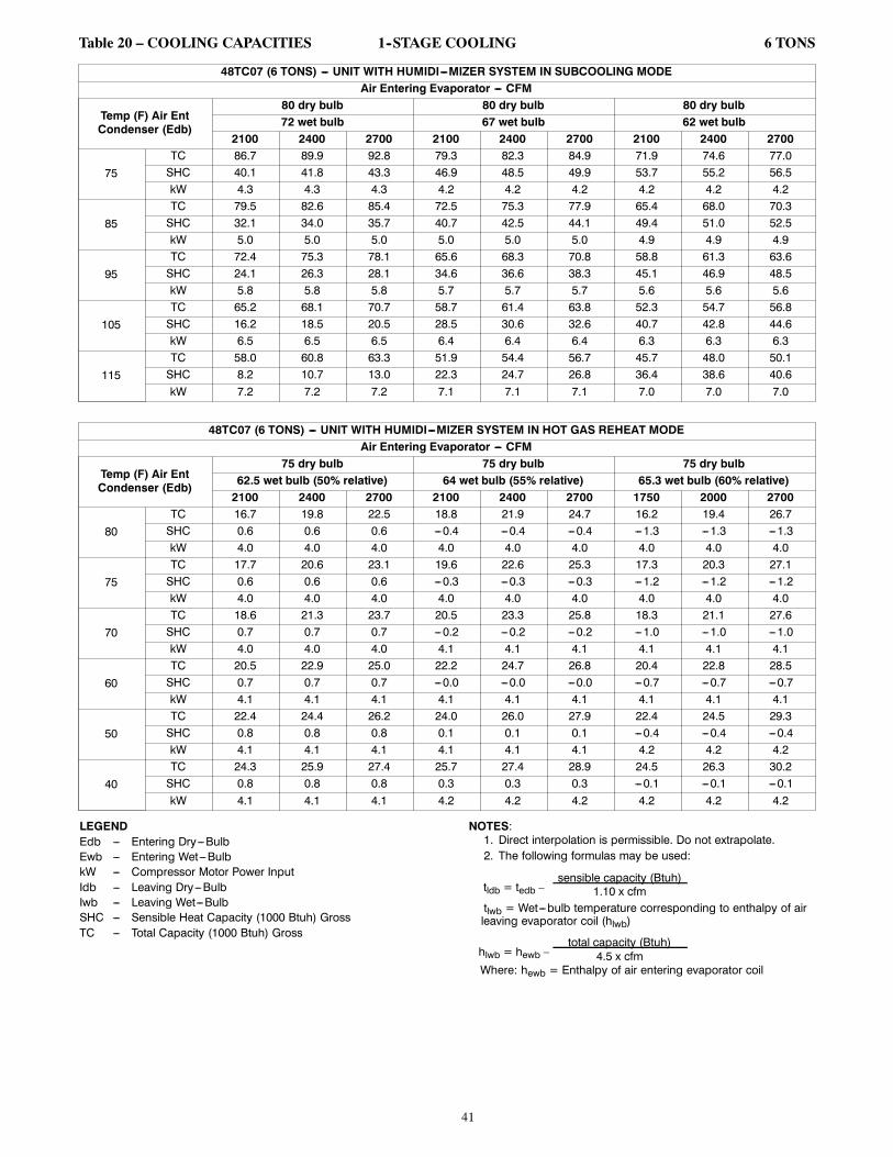
41
Table 20 – COOLING CAPACITIES 1--STAGE COOLING 6 TONS
48TC07 (6 TONS) --- UNIT WITH HUMIDI---MIZER SYSTEM IN SUBCOOLING MODEAir Entering Evaporator --- CFM
Temp (F) Air EntCondenser (Edb)
80 dry bulb 80 dry bulb 80 dry bulb72 wet bulb 67 wet bulb 62 wet bulb
2100 2400 2700 2100 2400 2700 2100 2400 2700
75TC 86.7 89.9 92.8 79.3 82.3 84.9 71.9 74.6 77.0SHC 40.1 41.8 43.3 46.9 48.5 49.9 53.7 55.2 56.5kW 4.3 4.3 4.3 4.2 4.2 4.2 4.2 4.2 4.2
85TC 79.5 82.6 85.4 72.5 75.3 77.9 65.4 68.0 70.3SHC 32.1 34.0 35.7 40.7 42.5 44.1 49.4 51.0 52.5kW 5.0 5.0 5.0 5.0 5.0 5.0 4.9 4.9 4.9
95TC 72.4 75.3 78.1 65.6 68.3 70.8 58.8 61.3 63.6SHC 24.1 26.3 28.1 34.6 36.6 38.3 45.1 46.9 48.5kW 5.8 5.8 5.8 5.7 5.7 5.7 5.6 5.6 5.6
105TC 65.2 68.1 70.7 58.7 61.4 63.8 52.3 54.7 56.8SHC 16.2 18.5 20.5 28.5 30.6 32.6 40.7 42.8 44.6kW 6.5 6.5 6.5 6.4 6.4 6.4 6.3 6.3 6.3
115TC 58.0 60.8 63.3 51.9 54.4 56.7 45.7 48.0 50.1SHC 8.2 10.7 13.0 22.3 24.7 26.8 36.4 38.6 40.6kW 7.2 7.2 7.2 7.1 7.1 7.1 7.0 7.0 7.0
48TC07 (6 TONS) --- UNIT WITH HUMIDI---MIZER SYSTEM IN HOT GAS REHEAT MODEAir Entering Evaporator --- CFM
Temp (F) Air EntCondenser (Edb)
75 dry bulb 75 dry bulb 75 dry bulb62.5 wet bulb (50% relative) 64 wet bulb (55% relative) 65.3 wet bulb (60% relative)2100 2400 2700 2100 2400 2700 1750 2000 2700
80TC 16.7 19.8 22.5 18.8 21.9 24.7 16.2 19.4 26.7SHC 0.6 0.6 0.6 ---0.4 ---0.4 ---0.4 ---1.3 ---1.3 ---1.3kW 4.0 4.0 4.0 4.0 4.0 4.0 4.0 4.0 4.0
75TC 17.7 20.6 23.1 19.6 22.6 25.3 17.3 20.3 27.1SHC 0.6 0.6 0.6 ---0.3 ---0.3 ---0.3 ---1.2 ---1.2 ---1.2kW 4.0 4.0 4.0 4.0 4.0 4.0 4.0 4.0 4.0
70TC 18.6 21.3 23.7 20.5 23.3 25.8 18.3 21.1 27.6SHC 0.7 0.7 0.7 ---0.2 ---0.2 ---0.2 ---1.0 ---1.0 ---1.0kW 4.0 4.0 4.0 4.1 4.1 4.1 4.1 4.1 4.1
60TC 20.5 22.9 25.0 22.2 24.7 26.8 20.4 22.8 28.5SHC 0.7 0.7 0.7 ---0.0 ---0.0 ---0.0 ---0.7 ---0.7 ---0.7kW 4.1 4.1 4.1 4.1 4.1 4.1 4.1 4.1 4.1
50TC 22.4 24.4 26.2 24.0 26.0 27.9 22.4 24.5 29.3SHC 0.8 0.8 0.8 0.1 0.1 0.1 ---0.4 ---0.4 ---0.4kW 4.1 4.1 4.1 4.1 4.1 4.1 4.2 4.2 4.2
40TC 24.3 25.9 27.4 25.7 27.4 28.9 24.5 26.3 30.2SHC 0.8 0.8 0.8 0.3 0.3 0.3 ---0.1 ---0.1 ---0.1kW 4.1 4.1 4.1 4.2 4.2 4.2 4.2 4.2 4.2
LEGENDEdb --- Entering Dry---BulbEwb --- Entering Wet---BulbkW --- Compressor Motor Power InputIdb --- Leaving Dry---BulbIwb --- Leaving Wet---BulbSHC --- Sensible Heat Capacity (1000 Btuh) GrossTC --- Total Capacity (1000 Btuh) Gross
NOTES:1. Direct interpolation is permissible. Do not extrapolate.2. The following formulas may be used:
tldb = tedb –sensible capacity (Btuh)
1.10 x cfmtlwb = Wet---bulb temperature corresponding to enthalpy of airleaving evaporator coil (hlwb)
hlwb = hewb –total capacity (Btuh)
4.5 x cfmWhere: hewb = Enthalpy of air entering evaporator coil

42
Table 21 – COOLING CAPACITIES 1--STAGE COOLING 7.5 TONS
48TC*A08(RTPF)
AMBIENT TEMPERATURE85 95 105 115
EAT (db) EAT (db) EAT (db) EA (db)75 80 85 75 80 85 75 80 85 75 80 85
2250Cfm
EAT(wb)
58TC 81.2 81.2 91.8 77.5 77.5 87.7 73.6 73.6 83.3 69.5 69.5 78.7SHC 70.5 81.2 91.8 67.3 77.5 87.7 63.9 73.6 83.3 60.4 69.5 78.7
62TC 86.9 86.9 86.9 82.3 82.3 84.0 77.2 77.2 81.5 71.9 71.9 78.8SHC 63.6 74.9 86.2 61.4 72.7 84.0 58.9 70.2 81.5 56.3 67.6 78.8
67TC 95.2 95.2 95.2 90.7 90.7 90.7 85.7 85.7 85.7 79.9 79.9 79.9SHC 52.8 64.2 75.6 50.9 62.2 73.6 48.8 60.1 71.5 46.3 57.6 68.9
72TC 103.5 103.5 103.5 98.9 98.9 98.9 93.8 93.8 93.8 87.3 87.3 87.3SHC 41.5 53.1 64.6 39.7 51.2 62.7 37.7 49.2 60.6 35.3 46.6 57.8
76TC --- 109.6 109.6 --- 104.8 104.8 --- 99.1 99.1 --- 91.6 91.6SHC --- 43.7 56.0 --- 42.0 54.3 --- 40.0 52.4 --- 37.4 49.8
2625Cfm
EAT(wb)
58TC 85.9 85.9 97.2 82.2 82.2 93.1 78.1 78.1 88.4 73.9 73.9 83.6SHC 74.6 85.9 97.2 71.4 82.2 93.1 67.9 78.1 88.4 64.1 73.9 83.6
62TC 89.6 89.6 94.1 85.1 85.1 91.7 80.1 80.1 89.1 74.6 74.6 86.0SHC 68.1 81.1 94.1 65.9 78.8 91.7 63.4 76.3 89.1 60.6 73.3 86.0
67TC 97.9 97.9 97.9 93.2 93.2 93.2 88.1 88.1 88.1 82.0 82.0 82.0SHC 55.7 68.7 81.7 53.7 66.7 79.8 51.6 64.6 77.6 49.0 62.0 74.9
72TC 106.0 106.0 106.0 101.3 101.3 101.3 95.9 95.9 95.9 89.0 89.0 89.0SHC 42.7 55.8 68.9 40.9 53.9 67.0 38.8 51.8 64.7 36.2 48.9 61.7
76TC --- 111.8 111.8 --- 106.9 106.9 --- 100.7 100.7 --- 92.7 92.7SHC --- 45.3 59.8 --- 43.6 58.0 --- 41.4 55.6 --- 38.7 52.6
3000Cfm
EAT(wb)
58TC 89.6 89.6 101.4 85.9 85.9 97.2 81.7 81.7 92.5 77.0 77.0 87.1SHC 77.9 89.6 101.4 74.6 85.9 97.2 71.0 81.7 92.5 66.9 77.0 87.1
62TC 91.8 91.8 101.1 87.2 87.2 98.6 82.3 82.3 95.5 77.1 77.1 90.6SHC 72.2 86.7 101.1 69.9 84.3 98.6 67.2 81.3 95.5 63.5 77.1 90.6
67TC 99.9 99.9 99.9 95.2 95.2 95.2 89.9 89.9 89.9 83.6 83.6 83.6SHC 58.3 72.9 87.5 56.4 71.0 85.5 54.2 68.8 83.4 51.6 66.1 80.5
72TC 107.9 107.9 107.9 103.0 103.0 103.0 97.3 97.3 97.3 90.1 90.1 90.1SHC 43.7 58.3 72.8 41.9 56.4 70.9 39.7 54.1 68.4 37.0 51.0 65.0
76TC --- 113.8 113.8 --- 108.4 108.4 --- 102.0 102.0 --- 93.4 93.4SHC --- 46.7 62.5 --- 44.8 60.4 --- 42.6 57.9 --- 39.6 54.7
3375Cfm
EAT(wb)
58TC 92.7 92.7 104.9 88.8 88.8 100.5 84.6 84.6 95.7 79.6 79.6 90.0SHC 80.5 92.7 104.9 77.1 88.8 100.5 73.4 84.6 95.7 69.1 79.6 90.0
62TC 93.7 93.7 107.3 89.1 89.1 104.7 84.6 84.6 99.5 79.6 79.6 93.6SHC 75.8 91.6 107.3 73.5 89.1 104.7 69.8 84.6 99.5 65.6 79.6 93.6
67TC 101.5 101.5 101.5 96.7 96.7 96.7 91.3 91.3 91.3 84.8 84.8 85.7SHC 60.8 76.9 93.0 58.8 74.9 91.0 56.7 72.8 88.9 53.9 69.8 85.7
72TC 109.4 109.4 109.4 104.3 104.3 104.3 98.4 98.4 98.4 90.9 90.9 90.9SHC 44.6 60.5 76.4 42.8 58.6 74.4 40.5 56.2 71.8 37.7 52.8 68.0
76TC --- 115.1 115.1 --- 109.5 109.5 --- 102.8 102.8 --- 94.0 94.0SHC --- 47.8 64.9 --- 45.9 62.7 --- 43.5 60.1 --- 40.4 56.5
3750Cfm
EAT(wb)
58TC 95.3 95.3 107.8 91.3 91.3 103.3 86.9 86.9 98.3 81.7 81.7 92.4SHC 82.7 95.3 107.8 79.3 91.3 103.3 75.5 86.9 98.3 70.9 81.7 92.4
62TC 95.5 95.5 112.2 91.3 91.3 107.4 87.0 87.0 102.2 81.7 81.7 96.0SHC 78.7 95.5 112.2 75.3 91.3 107.4 71.7 87.0 102.2 67.4 81.7 96.0
67TC 102.8 102.8 102.8 97.9 97.9 97.9 92.3 92.3 94.0 85.7 85.7 90.5SHC 63.1 80.6 98.2 61.2 78.7 96.3 59.0 76.5 94.0 56.0 73.2 90.5
72TC 110.6 110.6 110.6 105.4 105.4 105.4 99.2 99.2 99.2 91.5 91.5 91.5SHC 45.5 62.7 79.9 43.5 60.7 77.8 41.3 58.1 75.0 38.3 54.5 70.7
76TC --- 116.1 116.1 --- 110.3 110.3 --- 103.5 103.5 --- 94.5 94.5SHC --- 48.9 67.0 --- 46.8 64.8 --- 44.4 62.0 --- 41.1 58.1
LEGEND:--- --- Do not operate in this regionCfm --- Cubic feet per minute (supply air)EAT(db) --- Entering air temperature (dry bulb)EAT(wb) --- Entering air temperature (wet bulb)SHC --- Sensible heat capacityTC --- Total capacity

43
Table 22 – COOLING CAPACITIES 2--STAGE COOLING 7.5 TONS
48TC*D08(RTPF & Novation)
AMBIENT TEMPERATURE85 95 105 115
EAT (db) EAT (db) EAT (db) EA (db)75 80 85 75 80 85 75 80 85 75 80 85
2250Cfm
EAT(wb)
58TC 77.4 77.4 87.8 73.8 73.8 83.8 70.1 70.1 79.5 66.0 66.0 74.9SHC 66.9 77.4 87.8 63.9 73.8 83.8 60.6 70.1 79.5 57.1 66.0 74.9
62TC 82.2 82.2 83.9 77.5 77.5 81.7 72.6 72.6 79.2 67.3 67.3 76.4SHC 60.8 72.4 83.9 58.6 70.1 81.7 56.3 67.7 79.2 53.6 65.0 76.4
67TC 90.1 90.1 90.1 86.0 86.0 86.0 81.4 81.4 81.4 75.9 75.9 75.9SHC 50.2 61.8 73.3 48.5 60.1 71.6 46.5 58.1 69.7 44.2 55.8 67.4
72TC 98.0 98.0 98.0 94.0 94.0 94.0 89.5 89.5 89.5 84.3 84.3 84.3SHC 39.1 50.7 62.4 37.5 49.2 60.9 35.8 47.5 59.2 33.8 45.5 57.2
76TC --- 104.3 104.3 --- 100.4 100.4 --- 95.9 95.9 --- 90.7 90.7SHC --- 41.7 54.0 --- 40.3 52.7 --- 38.7 51.0 --- 36.8 49.0
2625Cfm
EAT(wb)
58TC 82.1 82.1 93.2 78.4 78.4 89.0 74.4 74.4 84.4 70.0 70.0 79.5SHC 71.0 82.1 93.2 67.8 78.4 89.0 64.3 74.4 84.4 60.6 70.0 79.5
62TC 84.9 84.9 91.8 80.4 80.4 89.5 75.4 75.4 86.7 70.2 70.2 82.9SHC 65.4 78.6 91.8 63.2 76.3 89.5 60.6 73.7 86.7 57.6 70.2 82.9
67TC 92.5 92.5 92.5 88.3 88.3 88.3 83.6 83.6 83.6 78.3 78.3 78.3SHC 53.0 66.3 79.5 51.3 64.6 78.0 49.4 62.8 76.1 47.2 60.6 73.9
72TC 100.4 100.4 100.4 96.4 96.4 96.4 91.7 91.7 91.7 86.4 86.4 86.4SHC 40.2 53.5 66.7 38.7 52.0 65.3 36.9 50.3 63.7 35.0 48.4 61.8
76TC --- 106.5 106.5 --- 102.6 102.6 --- 98.0 98.0 --- 92.7 92.7SHC --- 43.3 57.6 --- 41.8 55.9 --- 40.2 54.1 --- 38.4 52.2
3000Cfm
EAT(wb)
58TC 85.7 85.7 97.3 82.2 82.2 93.3 78.0 78.0 88.6 73.5 73.5 83.4SHC 74.1 85.7 97.3 71.1 82.2 93.3 67.5 78.0 88.6 63.6 73.5 83.4
62TC 86.9 86.9 98.7 82.8 82.8 96.4 78.2 78.2 92.3 73.6 73.6 86.9SHC 69.3 84.0 98.7 67.2 81.8 96.4 64.1 78.2 92.3 60.3 73.6 86.9
67TC 94.3 94.3 94.3 90.1 90.1 90.1 85.2 85.2 85.2 79.8 79.8 80.1SHC 55.6 70.5 85.4 54.0 68.9 83.9 52.1 67.1 82.2 49.9 65.0 80.1
72TC 102.2 102.2 102.2 98.1 98.1 98.1 93.3 93.3 93.3 87.9 87.9 87.9SHC 41.2 56.0 70.7 39.7 54.6 69.5 38.0 53.0 68.0 36.0 51.1 66.2
76TC --- 108.1 108.1 --- 104.2 104.2 --- 99.5 99.5 --- 94.2 94.2SHC --- 44.5 60.2 --- 43.2 58.7 --- 41.6 57.0 --- 39.8 55.2
3375Cfm
EAT(wb)
58TC 88.5 88.5 100.4 85.0 85.0 96.4 81.0 81.0 92 76.5 76.5 86.8SHC 76.5 88.5 100.4 73.5 85.0 96.4 70.1 81.0 92 66.1 76.5 86.8
62TC 88.9 88.9 103.9 85.1 85.1 100.4 81.1 81.1 95.7 76.5 76.5 90.3SHC 72.3 88.1 103.9 69.7 85.1 100.4 66.5 81.1 95.7 62.7 76.5 90.3
67TC 95.8 95.8 95.8 91.5 91.5 91.5 86.6 86.6 87.9 81.1 81.1 85.8SHC 58.0 74.4 90.9 56.4 73.0 89.6 54.6 71.3 87.9 52.4 69.1 85.8
72TC 103.6 103.6 103.6 99.4 99.4 99.4 94.6 94.6 94.6 89.1 89.1 89.1SHC 42.0 58.3 74.5 40.6 57.0 73.4 38.9 55.5 72.0 37.0 53.7 70.3
76TC --- 109.2 109.2 --- 105.4 105.4 --- 100.7 100.7 --- 95.3 95.3SHC --- 45.6 62.6 --- 44.4 61.3 --- 42.8 59.7 --- 41.0 58.0
3750Cfm
EAT(wb)
58TC 90.8 90.8 103.0 87.3 87.3 99.1 83.3 83.3 94.5 78.8 78.8 89.4SHC 78.5 90.8 103.0 75.5 87.3 99.1 72.0 83.3 94.5 68.2 78.8 89.4
62TC 90.9 90.9 107.2 87.4 87.4 103.1 83.3 83.3 98.4 78.9 78.9 93.1SHC 74.5 90.9 107.2 71.6 87.4 103.1 68.3 83.3 98.4 64.7 78.9 93.1
67TC 97.0 97.0 97.0 92.6 92.6 95.1 87.6 87.6 93.4 82.1 82.1 91.2SHC 60.3 78.2 96.2 58.8 76.9 95.1 56.9 75.2 93.4 54.8 73.0 91.2
72TC 104.7 104.7 104.7 100.5 100.5 100.5 95.6 95.6 95.6 90.1 90.1 90.1SHC 42.9 60.5 78.1 41.4 59.3 77.1 39.8 57.8 75.9 37.9 56.1 74.3
76TC --- 110.2 110.2 --- 106.2 106.2 --- 101.6 101.6 --- 96.1 96.1SHC --- 46.7 64.8 --- 45.4 63.6 --- 44.0 62.3 --- 42.2 60.6
* See Minimum---Maximum Airflow Ratings in Table 6. Do not operate outside these limits.LEGEND:--- --- Do not operate in this regionCfm --- Cubic feet per minute (supply air)EAT(db) --- Entering air temperature (dry bulb)EAT(wb) --- Entering air temperature (wet bulb)SHC --- Sensible heat capacityTC --- Total capacity

44
Table 23 – COOLING CAPACITIES 2--STAGE COOLING 7.5 TONS48TC08 COOLING CAPACITIES, UNIT WITH HUMIDI---MIZER SYSTEM IN SUBCOOLING MODE
TEMP (F) AIR ENTCONDENSER (Edb)
AIR ENTERING EVAPORATOR --- CFM2250/0.05 3000/0.07 3750/0.09
Air Entering Evaporator --- Ewb (F)72 67 62 72 67 62 72 67 62
75TC 103.05 93.02 83.60 109.77 99.52 90.08 114.01 103.69 95.19SHC 43.66 55.34 67.09 50.99 66.29 81.31 57.49 76.27 92.20kW 4.90 4.83 4.77 4.82 4.88 4.96 4.99 4.91 4.85
85TC 95.39 85.83 76.88 101.59 91.89 82.95 105.53 95.76 87.77SHC 36.42 48.47 60.60 43.24 58.99 74.40 49.44 68.68 84.90kW 5.49 5.42 5.36 5.40 5.47 5.54 5.58 5.50 5.44
95TC 87.48 78.44 69.97 93.21 84.05 75.61 96.84 87.63 80.14SHC 28.98 41.46 53.97 35.32 51.53 67.34 41.21 60.92 77.41kW 6.16 6.09 6.03 6.08 6.14 6.21 6.24 6.17 6.11
105TC 79.35 70.83 62.84 84.57 75.96 68.04 87.88 79.23 72.26SHC 21.34 34.26 47.18 27.17 43.86 60.08 32.73 52.95 69.70kW 6.93 6.86 6.81 6.85 6.91 6.97 7.00 6.93 6.88
115TC 70.87 62.89 55.42 75.58 67.54 60.15 78.56 70.51 64.06SHC 13.40 26.79 40.14 18.70 35.89 52.54 23.94 44.68 61.67kW 7.79 7.74 7.69 7.73 7.78 7.83 7.86 7.80 7.76
48TC08 COOLING CAPACITIES, UNIT WITH HUMIDI---MIZER SYSTEM IN HOT GAS REHEAT MODE
TEMP (F) AIR ENTCONDENSER (Edb)
AIR ENTERING EVAPORATOR --- Ewb (F)75 Dry Bulb62.5 Wet Bulb(50% Relative)
75 Dry Bulb64 Wet Bulb(56% Relative)
75 Dry Bulb65.3 Wet Bulb(60% Relative)
Air Entering Evaporator --- Cfm2250 3000 3750 2250 3000 3750 2250 3000 3750
80TC 27.60 32.75 30.19 40.09 39.43 37.73 45.06 45.25 44.25SHC ---3.12 5.20 6.71 3.75 5.24 6.75 3.77 5.26 6.78kW 4.56 4.51 4.46 4.63 4.60 4.56 4.70 4.67 4.64
75TC 35.40 33.78 31.20 41.14 40.51 38.80 46.15 46.37 45.38SHC 4.67 6.17 7.69 4.71 6.21 7.73 4.74 6.24 7.76kW 4.41 4.36 4.39 4.41 4.36 4.36 4.41 4.39 4.36
70TC 36.36 34.71 32.18 42.10 41.47 39.77 47.08 47.31 46.32SHC 5.63 7.14 8.66 5.67 7.18 8.71 5.70 7.21 8.74kW 4.43 4.49 4.41 4.44 4.40 4.39 4.49 4.47 4.44
60TC 38.25 36.64 34.15 43.97 43.37 41.72 48.98 49.22 48.26SHC 7.56 9.09 10.62 7.60 9.13 10.66 7.62 9.15 10.69kW 4.56 4.55 4.43 4.57 4.53 4.46 4.56 4.55 4.50
50TC 40.15 38.60 36.14 45.95 45.37 43.73 50.57 50.97 49.56SHC 9.48 11.03 12.58 9.52 11.07 12.62 9.54 11.10 12.64kW 4.63 4.52 4.38 4.45 4.41 4.33 5.25 4.91 5.60
40TC 42.18 40.62 38.11 47.80 47.25 45.43 52.65 52.75 51.83SHC 11.41 12.98 14.54 11.45 13.02 14.58 11.47 13.04 14.60kW 4.32 4.37 4.37 4.65 4.60 4.89 4.96 5.20 5.12
LEGENDEdb --- Entering Dry---BulbEwb --- Entering Wet---BulbkW --- Compressor Motor Power InputIdb --- Leaving Dry---BulbIwb --- Leaving Wet---BulbSHC --- Sensible Heat Capacity (1000 Btuh) GrossTC --- Total Capacity (1000 Btuh) Gross
NOTES:1. Direct interpolation is permissible. Do not extrapolate.2. The following formulas may be used:
tldb = tedb –sensible capacity (Btuh)
1.10 x cfmtlwb = Wet---bulb temperature corresponding to enthalpy of airleaving evaporator coil (hlwb)
hlwb = hewb –total capacity (Btuh)
4.5 x cfmWhere: hewb = Enthalpy of air entering evaporator coil

45
Table 24 – COOLING CAPACITIES 1--STAGE COOLING 8.5 TONS
48TC*A09(RTPF)
AMBIENT TEMPERATURE85 95 105 115
EAT (db) EAT (db) EAT (db) EAT (db)75 80 85 75 80 85 75 80 85 75 80 85
2550Cfm
EAT(wb)
58TC 88.1 88.1 99.9 84.1 84.1 95.3 79.6 79.6 90.3 74.9 74.9 84.9SHC 76.4 88.1 99.9 72.8 84.1 95.3 69.0 79.6 90.3 64.9 74.9 84.9
62TC 93.9 93.9 95.2 88.6 88.6 92.6 82.8 82.8 89.7 76.6 76.6 86.5SHC 69.4 82.3 95.2 66.8 79.7 92.6 64.1 76.9 89.7 61.0 73.8 86.5
67TC 103.8 103.8 103.8 98.7 98.7 98.7 93.0 93.0 93.0 86.7 86.7 86.7SHC 57.8 70.7 83.6 55.6 68.5 81.4 53.1 66.1 79.0 50.5 63.4 76.4
72TC 113.1 113.1 113.1 108.0 108.0 108.0 102.4 102.4 102.4 96.1 96.1 96.1SHC 45.2 58.3 71.3 43.2 56.3 69.3 41.1 54.1 67.1 38.7 51.7 64.7
76TC --- 119.9 119.9 --- 114.7 114.7 --- 109.0 109.0 --- 102.7 102.7SHC --- 47.9 61.9 --- 46.0 60.1 --- 44.1 58.1 --- 41.9 55.8
2975Cfm
EAT(wb)
58TC 93.6 93.6 106.1 89.3 89.3 101.2 84.6 84.6 96.0 79.6 79.6 90.3SHC 81.1 93.6 106.1 77.4 89.3 101.2 73.3 84.6 96.0 69.0 79.6 90.3
62TC 97.5 97.5 104.3 92.0 92.0 101.4 86.1 86.1 98.3 79.8 79.8 94.1SHC 74.7 89.5 104.3 72.0 86.7 101.4 69.1 83.7 98.3 65.6 79.8 94.1
67TC 106.7 106.7 106.7 101.5 101.5 101.5 95.7 95.7 95.7 89.2 89.2 89.2SHC 61.0 75.8 90.6 58.8 73.6 88.5 56.4 71.3 86.1 53.8 68.7 83.6
72TC 115.8 115.8 115.8 110.6 110.6 110.6 104.9 104.9 104.9 98.4 98.4 98.4SHC 46.5 61.3 76.2 44.5 59.4 74.2 42.3 57.2 72.1 40.0 54.8 69.7
76TC --- 122.4 122.4 --- 117.0 117.0 --- 111.1 111.1 --- 104.5 104.5SHC --- 49.8 66.1 --- 47.8 63.9 --- 45.7 61.6 --- 43.4 59.0
3400Cfm
EAT(wb)
58TC 98.1 98.1 111.3 93.7 93.7 106.2 88.9 88.9 100.8 83.7 83.7 94.9SHC 85.0 98.1 111.3 81.2 93.7 106.2 77.0 88.9 100.8 72.5 83.7 94.9
62TC 100.0 100.0 112.3 94.9 94.9 108.6 89.1 89.1 104.9 83.8 83.8 98.7SHC 79.3 95.8 112.3 76.3 92.5 108.6 73.2 89.1 104.9 68.8 83.8 98.7
67TC 109.0 109.0 109.0 103.6 103.6 103.6 97.6 97.6 97.6 91.0 91.0 91.0SHC 63.9 80.5 97.2 61.8 78.5 95.2 59.4 76.1 92.9 56.8 73.5 90.3
72TC 117.9 117.9 117.9 112.5 112.5 112.5 106.6 106.6 106.6 100.0 100.0 100.0SHC 47.6 64.1 80.6 45.6 62.1 78.7 43.4 60.0 76.6 41.1 57.6 74.2
76TC --- 124.2 124.2 --- 118.6 118.6 --- 112.5 112.5 --- 105.7 105.7SHC --- 51.2 69.0 --- 49.2 66.7 --- 47.0 64.4 --- 44.7 61.9
3825Cfm
EAT(wb)
58TC 101.6 101.6 115.1 97.2 97.2 110.1 92.3 92.3 104.6 87.0 87.0 98.6SHC 88.0 101.6 115.1 84.2 97.2 110.1 80.0 92.3 104.6 75.4 87.0 98.6
62TC 101.9 101.9 120.0 97.3 97.3 114.6 92.4 92.4 108.9 87.1 87.1 102.6SHC 83.7 101.8 120.0 79.9 97.3 114.6 75.9 92.4 108.9 71.6 87.1 102.6
67TC 110.7 110.7 110.7 105.3 105.3 105.3 99.2 99.2 99.3 92.5 92.5 96.7SHC 66.7 85.0 103.4 64.6 83.0 101.5 62.2 80.8 99.3 59.6 78.2 96.7
72TC 119.4 119.4 119.4 114.0 114.0 114.0 108.0 108.0 108.0 101.3 101.3 101.3SHC 48.5 66.6 84.6 46.6 64.7 82.7 44.4 62.6 80.7 42.1 60.2 78.4
76TC --- 125.5 125.5 --- 119.8 119.8 --- 113.6 113.6 --- 106.7 106.7SHC --- 52.4 71.5 --- 50.4 69.3 --- 48.2 67.0 --- 45.9 64.4
4250Cfm
EAT(wb)
58TC 104.4 104.4 118.3 99.9 99.9 113.2 95.0 95.0 107.6 89.5 89.5 101.5SHC 90.4 104.4 118.3 86.6 99.9 113.2 82.3 95.0 107.6 77.6 89.5 101.5
62TC 104.4 104.4 123.0 99.9 99.9 117.8 95.0 95.0 112.0 89.6 89.6 105.6SHC 85.8 104.4 123.0 82.1 99.9 117.8 78.1 95.0 112.0 73.6 89.6 105.6
67TC 112.1 112.1 112.1 106.6 106.6 107.5 100.4 100.4 105.3 93.6 93.6 102.7SHC 69.2 89.2 109.2 67.2 87.3 107.5 64.9 85.1 105.3 62.3 82.5 102.7
72TC 120.7 120.7 120.7 115.1 115.1 115.1 109.0 109.0 109.0 102.2 102.2 102.2SHC 49.4 68.9 88.4 47.4 67.0 86.5 45.3 64.9 84.6 42.9 62.6 82.3
76TC --- 126.6 126.6 --- 120.8 120.8 --- 114.5 114.5 --- 107.4 107.4SHC --- 53.5 73.9 --- 51.5 71.7 --- 49.3 69.4 --- 46.9 66.8
LEGEND:--- --- Do not operate in this regionCfm --- Cubic feet per minute (supply air)EAT(db) --- Entering air temperature (dry bulb)EAT(wb) --- Entering air temperature (wet bulb)SHC --- Sensible heat capacityTC --- Total capacity

46
Table 25 – COOLING CAPACITIES 2--STAGE COOLING 8.5 TONS
48TC*D09(RTPF)
AMBIENT TEMPERATURE85 95 105 115
EA (dB) EA (dB) EA (dB) EA (dB)75 80 85 75 80 85 75 80 85 75 80 85
2550Cfm
EAT(wb)
58TC 89.7 89.7 101.6 85.2 85.2 96.5 79.6 79.6 90.1 73.8 73.8 83.6SHC 77.8 89.7 101.6 73.9 85.2 96.5 69.0 79.6 90.1 64.0 73.8 83.6
62TC 94.3 94.3 97.9 88.7 88.7 95.2 81.3 81.3 91.5 74.3 74.3 86.5SHC 71.0 84.4 97.9 68.2 81.7 95.2 64.7 78.1 91.5 60.6 73.6 86.5
67TC 105.0 105.0 105.0 99.3 99.3 99.3 92.2 92.2 92.2 84.1 84.1 84.1SHC 59.0 72.6 86.1 56.6 70.1 83.7 53.6 67.1 80.7 50.3 63.8 77.3
72TC 115.9 115.9 115.9 110.4 110.4 110.4 104.2 104.2 104.2 96.0 96.0 96.0SHC 46.4 60.0 73.6 44.3 57.9 71.5 41.9 55.5 69.1 38.8 52.4 65.9
76TC --- 123.7 123.7 --- 118.3 118.3 --- 112.4 112.4 --- 105.7 105.7SHC --- 49.3 63.3 --- 47.3 61.4 --- 45.3 59.3 --- 42.9 56.7
2975Cfm
EAT(wb)
58TC 95.3 95.3 107.9 90.7 90.7 102.7 84.8 84.8 96.1 78.7 78.7 89.1SHC 82.6 95.3 107.9 78.6 90.7 102.7 73.5 84.8 96.1 68.2 78.7 89.1
62TC 97.9 97.9 107.8 92.1 92.1 104.7 85.4 85.4 99.4 78.8 78.8 92.8SHC 76.7 92.2 107.8 73.9 89.3 104.7 69.6 84.5 99.4 64.8 78.8 92.8
67TC 108.5 108.5 108.5 102.6 102.6 102.6 95.4 95.4 95.4 86.9 86.9 86.9SHC 62.8 78.4 94.1 60.4 76.0 91.7 57.4 73.1 88.8 54.0 69.7 85.3
72TC 119.1 119.1 119.1 113.5 113.5 113.5 107.2 107.2 107.2 99.2 99.2 99.2SHC 47.9 63.5 79.2 45.8 61.5 77.1 43.5 59.2 74.9 40.6 56.3 72.0
76TC --- 126.4 126.4 --- 120.8 120.8 --- 114.8 114.8 --- 108.2 108.2SHC --- 51.1 67.4 --- 49.2 65.3 --- 47.0 63.0 --- 44.8 60.7
3400Cfm
EAT(wb)
58TC 100.0 100.0 113.3 95.2 95.2 107.9 89.3 89.3 101.1 82.9 82.9 93.9SHC 86.7 100.0 113.3 82.6 95.2 107.9 77.4 89.3 101.1 71.8 82.9 93.9
62TC 101.1 101.1 115.8 95.7 95.7 111.7 89.4 89.4 105.3 83.0 83.0 97.7SHC 81.5 98.7 115.8 78.2 94.9 111.7 73.5 89.4 105.3 68.2 83.0 97.7
67TC 111.1 111.1 111.1 105.1 105.1 105.1 97.8 97.8 97.8 89.1 89.1 93.0SHC 66.2 83.9 101.6 63.9 81.6 99.3 61.0 78.7 96.5 57.5 75.3 93.0
72TC 121.3 121.3 121.3 115.6 115.6 115.6 109.4 109.4 109.4 101.5 101.5 101.5SHC 49.2 66.7 84.3 47.1 64.7 82.3 44.9 62.5 80.2 42.1 59.9 77.7
76TC --- 128.3 128.3 --- 122.6 122.6 --- 116.3 116.3 --- 109.7 109.7SHC --- 52.7 70.7 --- 50.7 68.6 --- 48.6 66.4 --- 46.4 64.2
3825Cfm
EAT(wb)
58TC 104.0 104.0 117.8 99.1 99.1 112.3 93.2 93.2 105.5 86.5 86.5 97.9SHC 90.2 104.0 117.8 86.0 99.1 112.3 80.8 93.2 105.5 75.0 86.5 97.9
62TC 104.2 104.2 122.7 99.3 99.3 116.9 93.3 93.3 109.8 86.6 86.6 101.9SHC 85.7 104.2 122.7 81.7 99.3 116.9 76.7 93.3 109.8 71.2 86.6 101.9
67TC 113.1 113.1 113.1 107.1 107.1 107.1 99.9 99.9 103.8 91.0 91.0 100.3SHC 69.4 89.1 108.8 67.1 86.8 106.5 64.3 84.1 103.8 60.9 80.6 100.3
72TC 123.0 123.0 123.0 117.2 117.2 117.2 110.9 110.9 110.9 103.3 103.3 103.3SHC 50.3 69.7 89.0 48.3 67.7 87.1 46.1 65.6 85.2 43.5 63.3 83.0
76TC --- 129.7 129.7 --- 124.0 124.0 --- 117.5 117.5 --- 110.8 110.8SHC --- 54.0 73.7 --- 52.1 71.7 --- 50.0 69.5 --- 47.8 67.4
4250Cfm
EAT(wb)
58TC 107.4 107.4 121.7 102.5 102.5 116.1 96.5 96.5 109.3 89.5 89.5 101.4SHC 93.1 107.4 121.7 88.9 102.5 116.1 83.7 96.5 109.3 77.6 89.5 101.4
62TC 107.5 107.5 126.6 102.6 102.6 120.8 96.6 96.6 113.7 89.6 89.6 105.5SHC 88.4 107.5 126.6 84.4 102.6 120.8 79.5 96.6 113.7 73.7 89.6 105.5
67TC 114.7 114.7 115.6 108.7 108.7 113.5 101.7 101.7 110.8 92.6 92.6 107.2SHC 72.5 94.0 115.6 70.2 91.8 113.5 67.5 89.2 110.8 64.0 85.6 107.2
72TC 124.3 124.3 124.3 118.5 118.5 118.5 112.1 112.1 112.1 104.7 104.7 104.7SHC 51.3 72.4 93.4 49.3 70.5 91.7 47.2 68.5 89.9 44.7 66.4 88.1
76TC --- 130.7 130.7 --- 125.0 125.0 --- 118.5 118.5 --- 111.6 111.6SHC --- 55.3 76.5 --- 53.5 74.6 --- 51.3 72.4 --- 49.2 70.3
* See Minimum---Maximum Airflow Ratings in Table 6. Do not operate outside these limits.LEGEND:--- --- Do not operate in this regionCfm --- Cubic feet per minute (supply air)EAT(db) --- Entering air temperature (dry bulb)EAT(wb) --- Entering air temperature (wet bulb)SHC --- Sensible heat capacityTC --- Total capacity

47
Table 26 – COOLING CAPACITIES 2--STAGE COOLING 8.5 TONS48TC09 COOLING CAPACITIES, UNIT WITH HUMIDI---MIZER SYSTEM IN SUBCOOLING MODE
TEMP (F) AIR ENTCONDENSER (Edb)
AIR ENTERING EVAPORATOR --- CFM2550/0.04 3400/0.05 4250/0.07
Air Entering Evaporator --- Ewb (F)72 67 62 72 67 62 72 67 62
75TC 119.20 107.44 96.41 126.95 114.98 103.92 131.87 119.81 109.54SHC 50.63 63.94 77.40 59.17 76.72 94.21 66.80 88.44 108.22kW 5.67 5.57 5.47 5.54 5.63 5.74 5.79 5.68 5.59
85TC 110.40 99.22 88.76 117.63 106.26 95.77 122.21 110.77 101.07SHC 42.39 56.16 70.07 50.42 68.45 86.38 57.71 79.86 99.95kW 6.33 6.23 6.14 6.20 6.30 6.40 6.45 6.34 6.25
95TC 101.37 90.79 80.86 108.07 97.31 87.39 112.29 101.47 92.38SHC 33.97 48.22 62.56 41.46 60.01 78.39 48.40 71.09 91.47kW 7.08 6.99 6.90 6.96 7.05 7.16 7.20 7.09 7.01
105TC 92.04 82.06 72.71 98.19 88.05 78.72 102.07 91.86 83.40SHC 25.31 40.06 54.88 32.24 51.33 70.17 38.85 62.06 82.67kW 7.94 7.85 7.77 7.83 7.91 8.01 8.06 7.95 7.87
115TC 82.37 73.01 64.24 87.95 78.45 69.73 91.46 81.90 74.09SHC 16.38 31.65 46.95 22.71 42.37 61.69 28.94 52.74 73.52kW 8.92 8.84 8.77 8.82 8.89 8.98 9.02 8.93 8.86
48TC09 COOLING CAPACITIES, UNIT WITH HUMIDI---MIZER SYSTEM IN HOT GAS REHEAT MODE
TEMP (F) AIR ENTCONDENSER (Edb)
AIR ENTERING EVAPORATOR --- Ewb (F)75 Dry Bulb62.5 Wet Bulb(50% Relative)
75 Dry Bulb64 Wet Bulb(56% Relative)
75 Dry Bulb65.3 Wet Bulb(60% Relative)
Air Entering Evaporator --- Cfm2550 3400 4250 2550 3400 4250 2550 3400 4250
80TC 37.61 33.13 26.77 44.74 41.60 36.46 50.96 48.99 44.93SHC ---0.52 ---0.63 ---0.73 ---0.46 ---0.57 ---0.67 ---0.42 ---0.53 ---0.62kW 5.88 5.68 5.44 6.13 5.97 5.76 6.35 6.24 6.06
75TC 38.71 34.24 27.86 45.84 42.73 37.59 52.05 50.11 46.06SHC 0.45 0.34 0.25 0.50 0.40 0.31 0.54 0.44 0.36kW 5.68 5.47 5.22 5.94 5.78 5.56 6.18 6.07 5.88
70TC 39.70 35.25 28.83 46.80 43.70 38.59 52.97 51.04 47.02SHC 1.41 1.32 1.23 1.47 1.37 1.29 1.50 1.41 1.34kW 5.65 5.42 5.24 5.97 5.79 5.53 6.26 6.13 5.91
60TC 41.77 37.33 30.76 48.86 45.80 40.71 55.00 53.10 49.12SHC 3.34 3.26 3.18 3.40 3.32 3.25 3.43 3.36 3.29kW 5.42 5.15 5.17 5.80 5.59 5.30 6.16 6.01 5.75
50TC 43.83 39.27 32.61 50.92 47.89 42.70 57.04 55.16 51.22SHC 5.27 5.21 5.14 5.32 5.27 5.21 5.36 5.31 5.25kW 5.18 5.15 5.17 5.62 5.39 5.05 6.04 5.87 5.59
40TC 45.75 41.13 34.50 53.08 50.00 44.64 59.24 57.40 53.44SHC 7.20 7.15 6.95 7.26 7.21 7.16 7.29 7.25 7.21kW 4.79 4.98 4.80 5.25 5.01 5.23 5.68 5.51 5.21
LEGENDEdb --- Entering Dry---BulbEwb --- Entering Wet---BulbkW --- Compressor Motor Power InputIdb --- Leaving Dry---BulbIwb --- Leaving Wet---BulbSHC --- Sensible Heat Capacity (1000 Btuh) GrossTC --- Total Capacity (1000 Btuh) Gross
NOTES:1. Direct interpolation is permissible. Do not extrapolate.2. The following formulas may be used:
tldb = tedb –sensible capacity (Btuh)
1.10 x cfmtlwb = Wet---bulb temperature corresponding to enthalpy of airleaving evaporator coil (hlwb)
hlwb = hewb –total capacity (Btuh)
4.5 x cfmWhere: hewb = Enthalpy of air entering evaporator coil

48
Table 27 – COOLING CAPACITIES 1--STAGE COOLING 10 TONS
48TC*A12(RTPF)
AMBIENT TEMPERATURE85 95 105 115
EAT (db) EAT (db) EAT (db) EAT (db)75 80 85 75 80 85 75 80 85 75 80 85
3000Cfm
EAT(wb)
58TC 106.3 106.3 120.5 101.7 101.7 115.2 96.6 96.6 109.4 91.0 91.0 103.1SHC 92.2 106.3 120.5 88.2 101.7 115.2 83.8 96.6 109.4 78.9 91.0 103.1
62TC 112.5 112.5 115.2 106.5 106.5 112.3 99.9 99.9 109.0 92.7 92.7 105.2SHC 83.8 99.5 115.2 81.0 96.6 112.3 77.8 93.4 109.0 74.2 89.7 105.2
67TC 123.5 123.5 123.5 117.8 117.8 117.8 111.3 111.3 111.3 104.0 104.0 104.0SHC 69.2 85.0 100.7 66.8 82.5 98.3 64.1 79.8 95.5 61.0 76.8 92.5
72TC 134.3 134.3 134.3 128.5 128.5 128.5 122.0 122.0 122.0 114.7 114.7 114.7SHC 53.8 69.6 85.5 51.6 67.4 83.2 49.1 64.9 80.7 46.3 62.1 77.9
76TC --- 142.4 142.4 --- 136.3 136.3 --- 129.5 129.5 --- 121.8 121.8SHC --- 56.8 73.3 --- 54.7 71.2 --- 52.3 68.8 --- 49.7 66.2
3500Cfm
EAT(wb)
58TC 112.9 112.9 127.8 108.0 108.0 122.3 102.7 102.7 116.3 96.8 96.8 109.7SHC 97.9 112.9 127.8 93.6 108.0 122.3 89.0 102.7 116.3 83.9 96.8 109.7
62TC 116.3 116.3 126.2 110.5 110.5 123.3 103.8 103.8 119.5 97.1 97.1 114.3SHC 90.2 108.2 126.2 87.4 105.3 123.3 84.0 101.8 119.5 79.8 97.1 114.3
67TC 126.9 126.9 126.9 120.9 120.9 120.9 114.3 114.3 114.3 106.8 106.8 106.8SHC 73.2 91.3 109.4 70.8 88.9 107.1 68.1 86.2 104.4 65.0 83.2 101.3
72TC 137.5 137.5 137.5 131.4 131.4 131.4 124.7 124.7 124.7 117.2 117.2 117.2SHC 55.3 73.4 91.5 53.1 71.1 89.2 50.6 68.7 86.7 47.8 65.9 83.9
76TC --- 145.1 145.1 --- 138.8 138.8 --- 131.7 131.7 --- 123.6 123.6SHC --- 59.0 78.2 --- 56.7 75.8 --- 54.3 73.1 --- 51.5 70.0
4000Cfm
EAT(wb)
58TC 117.8 117.8 133.5 113.0 113.0 128.0 107.5 107.5 121.8 101.5 101.5 115.0SHC 102.2 117.8 133.5 98.0 113.0 128.0 93.3 107.5 121.8 88.0 101.5 115.0
62TC 119.1 119.1 136.0 113.5 113.5 132.5 107.7 107.7 126.7 101.6 101.6 119.6SHC 95.8 115.9 136.0 92.8 112.6 132.5 88.6 107.7 126.7 83.6 101.6 119.6
67TC 129.4 129.4 129.4 123.3 123.3 123.3 116.5 116.5 116.5 108.9 108.9 109.8SHC 76.9 97.3 117.7 74.5 95.0 115.4 71.8 92.3 112.8 68.8 89.3 109.8
72TC 139.7 139.7 139.7 133.5 133.5 133.5 126.6 126.6 126.6 118.8 118.8 118.8SHC 56.7 76.8 97.0 54.4 74.6 94.7 51.9 72.1 92.3 49.1 69.3 89.5
76TC --- 147.0 147.0 --- 140.5 140.5 --- 133.2 133.2 --- 124.9 124.9SHC --- 60.6 81.7 --- 58.4 79.3 --- 55.8 76.5 --- 53.0 73.5
4500Cfm
EAT(wb)
58TC 121.7 121.7 137.9 116.8 116.8 132.3 111.2 111.2 126.0 105.0 105.0 118.9SHC 105.6 121.7 137.9 101.3 116.8 132.3 96.4 111.2 126.0 91.0 105.0 118.9
62TC 121.8 121.8 143.4 116.9 116.9 137.6 111.3 111.3 131.0 105.1 105.1 123.7SHC 100.2 121.8 143.4 96.1 116.9 137.6 91.6 111.3 131.0 86.5 105.1 123.7
67TC 131.3 131.3 131.3 125.1 125.1 125.1 118.2 118.2 120.8 110.5 110.5 117.7SHC 80.3 102.9 125.5 78.0 100.7 123.3 75.3 98.0 120.8 72.3 95.0 117.7
72TC 141.5 141.5 141.5 135.1 135.1 135.1 128.0 128.0 128.0 120.1 120.1 120.1SHC 57.9 80.0 102.1 55.6 77.7 99.9 53.1 75.2 97.4 50.3 72.4 94.6
76TC --- 148.3 148.3 --- 141.8 141.8 --- 134.3 134.3 --- 125.8 125.8SHC --- 62.1 84.9 --- 59.8 82.5 --- 57.3 79.7 --- 54.4 76.6
5000Cfm
EAT(wb)
58TC 125.0 125.0 141.6 120.0 120.0 135.9 114.3 114.3 129.5 107.9 107.9 122.3SHC 108.4 125.0 141.6 104.0 120.0 135.9 99.1 114.3 129.5 93.6 107.9 122.3
62TC 125.1 125.1 147.2 120.1 120.1 141.4 114.4 114.4 134.7 108.0 108.0 127.2SHC 102.9 125.1 147.2 98.8 120.1 141.4 94.1 114.4 134.7 88.9 108.0 127.2
67TC 132.8 132.8 133.0 126.5 126.5 130.8 119.6 119.6 128.2 111.8 111.8 125.1SHC 83.6 108.3 133.0 81.2 106.0 130.8 78.6 103.4 128.2 75.6 100.3 125.1
72TC 142.8 142.8 142.8 136.3 136.3 136.3 129.1 129.1 129.1 121.1 121.1 121.1SHC 59.0 82.9 106.9 56.7 80.7 104.7 54.1 78.2 102.2 51.3 75.4 99.4
76TC --- 149.4 149.4 --- 142.8 142.8 --- 135.1 135.1 --- 126.5 126.5SHC --- 63.4 87.9 --- 61.2 85.5 --- 58.6 82.7 --- 55.6 79.4
LEGEND:--- --- Do not operate in this regionCfm --- Cubic feet per minute (supply air)EAT(db) --- Entering air temperature (dry bulb)EAT(wb) --- Entering air temperature (wet bulb)SHC --- Sensible heat capacityTC --- Total capacity

49
Table 28 – COOLING CAPACITIES 2--STAGE COOLING 10 TONS
48TC*D12(RTPF & Novation)
AMBIENT TEMPERATURE85 95 105 115
EAT (db) EAT (db) EAT (db) EAT (db)75 80 85 75 80 85 75 80 85 75 80 85
3000Cfm
EAT(wb)
58TC 107.6 107.6 121.9 102.5 102.5 116.2 96.8 96.8 109.7 90.5 90.5 102.6SHC 93.2 107.6 121.9 88.8 102.5 116.2 83.9 96.8 109.7 78.4 90.5 102.6
62TC 113.6 113.6 116.5 107.1 107.1 113.4 99.7 99.7 109.8 91.8 91.8 104.9SHC 84.6 100.6 116.5 81.5 97.4 113.4 78.0 93.9 109.8 73.7 89.3 104.9
67TC 124.4 124.4 124.4 118.4 118.4 118.4 111.5 111.5 111.5 103.3 103.3 103.3SHC 69.7 85.7 101.7 67.1 83.2 99.2 64.3 80.3 96.3 60.8 76.8 92.8
72TC 135.8 135.8 135.8 129.7 129.7 129.7 122.8 122.8 122.8 115 115 115SHC 54.3 70.4 86.6 52.0 68.1 84.2 49.3 65.4 81.6 46.4 62.5 78.6
76TC --- 145.3 145.3 --- 139 139 --- 131.9 131.9 --- 124.1 124.1SHC --- 57.8 74.3 --- 55.6 72.1 --- 53.1 69.6 --- 50.4 66.9
3500Cfm
EAT(wb)
58TC 114.2 114.2 129.4 108.9 108.9 123.4 102.9 102.9 116.6 96.3 96.3 109.1SHC 98.9 114.2 129.4 94.3 108.9 123.4 89.1 102.9 116.6 83.4 96.3 109.1
62TC 117.2 117.2 127.9 111.0 111.0 124.7 104.0 104.0 119.5 96.5 96.5 113.7SHC 91.1 109.5 127.9 88.1 106.4 124.7 83.9 101.7 119.5 79.3 96.5 113.7
67TC 127.8 127.8 127.8 121.7 121.7 121.7 114.5 114.5 114.5 106.6 106.6 106.6SHC 73.8 92.3 110.8 71.3 89.8 108.3 68.4 87.0 105.5 65.2 83.8 102.3
72TC 139.4 139.4 139.4 133.0 133.0 133 125.8 125.8 125.8 117.9 117.9 117.9SHC 56.0 74.6 93.1 53.7 72.2 90.8 51.0 69.6 88.2 48.1 66.7 85.4
76TC --- 148.8 148.8 --- 142.2 142.2 --- 134.9 134.9 --- 126.8 126.8SHC --- 60.2 79.5 --- 58.0 77.1 --- 55.4 74.5 --- 52.7 71.6
4000Cfm
EAT(wb)
58TC 119.0 119.0 134.9 114.0 114.0 129.2 108.0 108.0 122.4 101.1 101.1 114.6SHC 103.1 119.0 134.9 98.7 114.0 129.2 93.6 108.0 122.4 87.6 101.1 114.6
62TC 120.3 120.3 137.1 114.7 114.7 132.8 108.2 108.2 127.5 101.3 101.3 119.3SHC 96.5 116.8 137.1 93.0 112.9 132.8 88.9 108.2 127.5 83.2 101.3 119.3
67TC 130.5 130.5 130.5 124.1 124.1 124.1 116.8 116.8 116.8 108.7 108.7 111.1SHC 77.7 98.6 119.5 75.2 96.2 117.2 72.3 93.3 114.4 69.1 90.1 111.1
72TC 142.1 142.1 142.1 135.5 135.5 135.5 128.2 128.2 128.2 120.0 120.0 120.0SHC 57.6 78.4 99.3 55.2 76.1 97.1 52.5 73.6 94.6 49.7 70.7 91.8
76TC --- 151.4 151.4 --- 144.7 144.7 --- 137.1 137.1 --- --- ---SHC --- 62.3 83.8 --- 60.0 81.4 --- 57.5 78.8 --- --- ---
4500Cfm
EAT(wb)
58TC 123.0 123.0 139.5 117.8 117.8 133.6 111.9 111.9 126.9 105.3 105.3 119.3SHC 106.6 123.0 139.5 102.1 117.8 133.6 97.0 111.9 126.9 91.2 105.3 119.3
62TC 123.4 123.4 144.4 117.9 117.9 139.0 112.0 112.0 132.0 105.4 105.4 124.2SHC 100.9 122.7 144.4 96.9 117.9 139 92.1 112.0 132 86.6 105.4 124.2
67TC 132.6 132.6 132.6 126.0 126 126.0 118.7 118.7 122.9 110.4 110.4 119.6SHC 81.4 104.6 127.9 78.9 102.3 125.7 76.1 99.5 122.9 72.9 96.2 119.6
72TC 144.2 144.2 144.2 137.4 137.4 137.4 129.9 129.9 129.9 121.6 121.6 121.6SHC 59.0 82.1 105.2 56.6 79.8 103.1 54.0 77.3 100.7 51.1 74.5 98
76TC --- 153.4 153.4 --- 146.6 146.6 --- 138.9 138.9 --- --- ---SHC --- 64.1 87.8 --- 61.9 85.6 --- 59.4 83 --- --- ---
5000Cfm
EAT(wb)
58TC 126.5 126.5 143.3 121.2 121.2 137.4 115.1 115.1 130.5 108.4 108.4 122.8SHC 109.6 126.5 143.3 105.0 121.2 137.4 99.8 115.1 130.5 93.9 108.4 122.8
62TC 126.5 126.5 149.1 121.3 121.3 142.9 115.2 115.2 135.8 108.5 108.5 127.8SHC 104.0 126.5 149.1 99.7 121.3 142.9 94.7 115.2 135.8 89.1 108.5 127.8
67TC 134.2 134.2 135.9 127.5 127.5 133.8 120.1 120.1 131.0 111.9 111.9 127.6SHC 84.9 110.4 135.9 82.4 108.1 133.8 79.6 105.3 131 76.4 102.0 127.6
72TC 145.8 145.8 145.8 139.0 139.0 139.0 131.3 131.3 131.3 122.9 122.9 122.9SHC 60.3 85.6 110.8 57.9 83.4 108.9 55.3 81.0 106.6 52.5 78.2 104
76TC --- 155.1 155.1 --- 148.2 148.2 --- --- --- --- --- ---SHC --- 65.9 91.5 --- 63.7 89.5 --- --- --- --- --- ---
* See Minimum---Maximum Airflow Ratings in Table 6. Do not operate outside these limits.LEGEND:--- --- Do not operate in this regionCfm --- Cubic feet per minute (supply air)EAT(db) --- Entering air temperature (dry bulb)EAT(wb) --- Entering air temperature (wet bulb)SHC --- Sensible heat capacityTC --- Total capacity

50
Table 29 – COOLING CAPACITIES 2--STAGE COOLING 10 TONS48TC12 COOLING CAPACITIES, UNIT WITH HUMIDI---MIZER SYSTEM IN SUBCOOLING MODE
TEMP (F) AIR ENTCONDENSER (Edb)
AIR ENTERING EVAPORATOR --- CFM3000/0.04 4000/0.06 5000/0.07
Air Entering Evaporator --- Ewb (F)72 67 62 72 67 62 72 67 62
75TC 142.85 129.44 116.93 152.09 138.44 125.76 157.99 144.23 132.06SHC 58.38 74.88 91.58 67.96 89.45 111.02 76.63 102.94 127.93kW 7.19 6.97 6.79 6.92 7.12 7.35 7.45 7.22 7.02
85TC 132.33 119.68 107.86 140.92 128.03 116.10 146.41 133.41 121.98SHC 48.44 65.56 82.83 57.37 79.50 101.68 65.65 92.58 118.12kW 7.98 7.77 7.58 7.72 7.92 8.14 8.25 8.01 7.82
95TC 121.41 109.52 98.43 129.35 117.22 106.04 134.43 122.20 111.50SHC 38.19 55.92 73.78 46.47 69.22 92.01 54.34 81.92 107.96kW 8.87 8.66 8.48 8.61 8.80 9.03 9.14 8.90 8.71
105TC 110.04 98.92 88.56 117.27 105.94 95.53 121.88 110.46 100.54SHC 27.59 45.94 64.39 35.16 58.57 81.98 42.56 70.82 97.40kW 9.86 9.66 9.48 9.61 9.79 10.02 10.12 9.89 9.70
115TC 98.09 87.74 78.13 104.62 94.08 84.45 108.76 98.13 89.01SHC 16.52 35.47 54.53 23.37 47.44 71.46 30.32 59.25 86.31kW 10.95 10.76 10.60 10.72 10.89 11.10 11.19 10.98 10.81
48TC12 COOLING CAPACITIES, UNIT WITH HUMIDI---MIZER SYSTEM IN HOT GAS REHEAT MODE
TEMP (F) AIR ENTCONDENSER (Edb)
AIR ENTERING EVAPORATOR --- Ewb (F)75 Dry Bulb62.5 Wet Bulb(50% Relative)
75 Dry Bulb64 Wet Bulb(56% Relative)
75 Dry Bulb65.3 Wet Bulb(60% Relative)
Air Entering Evaporator --- Cfm3000 4000 5000 3000 4000 5000 3000 4000 5000
80TC 44.78 39.41 31.89 53.22 49.44 43.38 60.56 58.12 53.32SHC ---0.44 ---0.57 ---0.69 ---0.37 ---0.51 ---0.61 ---0.33 ---0.46 ---0.56kW 6.96 6.77 6.52 7.26 7.13 6.91 7.54 7.45 7.27
75TC 45.84 40.46 32.86 54.28 50.51 44.45 61.61 59.19 54.40SHC 0.53 0.40 0.29 0.60 0.47 0.37 0.64 0.52 0.42kW 6.77 6.56 6.29 7.11 6.95 6.72 7.41 7.31 7.12
70TC 46.91 41.48 33.50 55.36 51.59 45.50 62.69 60.28 55.49SHC 1.51 1.38 1.27 1.57 1.45 1.35 1.61 1.50 1.40kW 6.54 6.32 6.02 6.90 6.74 6.49 7.23 7.13 6.92
60TC 48.88 43.42 35.76 57.29 53.56 47.48 64.56 62.16 57.42SHC 3.44 3.34 3.24 3.51 3.40 3.31 3.55 3.45 3.37kW 6.45 6.16 6.70 6.93 6.72 6.39 7.38 7.24 6.96
50TC 50.83 45.28 37.67 59.22 55.52 49.43 66.05 64.03 59.34SHC 5.38 5.29 5.20 5.45 5.36 5.28 5.48 5.40 5.33kW 6.46 6.01 6.34 6.98 6.71 6.29 8.15 7.38 7.02
40TC 52.82 47.29 39.50 61.14 57.48 51.39 68.23 65.88 61.25SHC 7.32 7.24 7.20 7.38 7.31 7.24 7.43 7.36 7.29kW 6.29 6.09 6.12 7.05 6.72 6.29 7.78 7.55 7.10
LEGENDEdb --- Entering Dry---BulbEwb --- Entering Wet---BulbkW --- Compressor Motor Power InputIdb --- Leaving Dry---BulbIwb --- Leaving Wet---BulbSHC --- Sensible Heat Capacity (1000 Btuh) GrossTC --- Total Capacity (1000 Btuh) Gross
NOTES:1. Direct interpolation is permissible. Do not extrapolate.2. The following formulas may be used:
tldb = tedb –sensible capacity (Btuh)
1.10 x cfmtlwb = Wet---bulb temperature corresponding to enthalpy of airleaving evaporator coil (hlwb)
hlwb = hewb –total capacity (Btuh)
4.5 x cfmWhere: hewb = Enthalpy of air entering evaporator coil

51
Table 30 – COOLING CAPACITIES 2--STAGE COOLING 12.5 TONS
48TC*D14(RTPF & Novation)
AMBIENT TEMPERATURE85 95 105 115
EAT (db) EAT (db) EAT (db) EAT (db)75 80 85 75 80 85 75 80 85 75 80 85
3600Cfm
EAT(wb)
58TC 127.6 127.6 142.9 121.7 121.7 137.6 115.0 115.0 130 108.3 108.3 122.6SHC 110.3 126.6 142.9 105.8 121.7 137.6 99.9 115.0 130 94.1 108.3 122.6
62TC 136.1 136.1 136.1 131.1 131.1 131.1 123.8 123.8 124.5 114.9 114.9 120.3SHC 96.6 112.8 129.0 94.7 111.2 127.7 91.4 108.0 124.5 87.3 103.8 120.3
67TC 146.2 146.2 146.2 142.0 142.0 142.0 136.2 136.2 136.2 128.8 128.8 128.8SHC 78.5 94.4 110.3 76.9 93.1 109.2 74.7 91.0 107.3 71.7 88.1 104.6
72TC 155.9 155.9 155.9 152.4 152.4 152.4 147.2 147.2 147.2 140.1 140.1 140.1SHC 60.1 76.6 93.2 58.7 75.2 91.7 56.8 73.3 89.7 54.2 70.6 87.0
76TC --- 163.0 163 --- 160.0 160 --- 155.1 155.1 --- 148.2 148.2SHC --- 62.0 81.8 --- 61.1 80.9 --- 59.5 79.3 --- 57.0 76.3
4200Cfm
EAT(wb)
58TC 132.2 132.2 149.5 128.2 128.2 144.9 121.9 121.9 137.8 115.0 115.0 130.1SHC 115.0 132.2 149.5 111.5 128.2 144.9 106.0 121.9 137.8 99.9 115.0 130.1
62TC 139.6 139.6 139.6 134.7 134.7 138 128.0 128.0 135.6 119.1 119.1 131.2SHC 102.5 120.8 139 100.8 119.4 138 98.1 116.8 135.6 93.9 112.6 131.2
67TC 149.5 149.5 149.5 145.4 145.4 145.4 139.6 139.6 139.6 132.1 132.1 132.1SHC 81.8 99.6 117.4 80.6 98.7 116.8 78.5 96.9 115.2 75.7 94.3 112.8
72TC 159.0 159.0 159.0 155.5 155.5 155.5 150.3 150.3 150.3 143.1 143.1 143.1SHC 61.4 79.6 97.8 60.2 78.5 96.8 58.3 76.7 95 55.8 74.2 92.5
76TC --- 165.7 165.7 --- 162.8 162.8 --- 157.8 157.8 --- 150.8 150.8SHC --- 64.6 87.7 --- 63.5 86.3 --- 61.5 83.3 --- 58.9 79.9
4800Cfm
EAT(wb)
58TC 136.7 136.7 154.5 133.0 133.0 150.3 127.7 127.7 144.3 120.6 120.6 136.4SHC 118.9 136.7 154.5 115.7 133.0 150.3 111.0 127.7 144.3 104.9 120.6 136.4
62TC 142.2 142.2 147.8 137.4 137.4 147.1 131.0 131.0 144.7 122.8 122.8 140.3SHC 107.7 127.8 147.8 106.2 126.7 147.1 103.6 124.2 144.7 99.3 119.8 140.3
67TC 152.1 152.1 152.1 148.0 148 148 142.2 142.2 142.2 134.6 134.6 134.6SHC 84.8 104.3 123.7 83.8 103.8 123.7 82.0 102.3 122.6 79.4 99.9 120.4
72TC 161.3 161.3 161.3 157.8 157.8 157.8 152.5 152.5 152.5 145.4 145.4 145.4SHC 62.6 82.2 101.9 61.4 81.4 101.3 59.7 79.7 99.8 57.2 77.3 97.5
76TC --- 167.7 167.7 --- 164.9 164.9 --- 159.9 159.9 --- 152.8 152.8SHC --- 66.4 91.4 --- 65 89.2 --- 63.1 86.4 --- 60.5 83.1
5400Cfm
EAT(wb)
58TC 140.5 140.5 158.8 136.9 136.9 154.7 131.8 131.8 149 125.2 125.2 141.6SHC 122.2 140.5 158.8 119 136.9 154.7 114.7 131.8 149 108.9 125.2 141.6
62TC 144.3 144.3 155.7 139.6 139.6 155 133.5 133.5 152.4 125.8 125.8 147.8SHC 112.2 133.9 155.7 110.9 132.9 155 108.1 130.2 152.4 103.9 125.8 147.8
67TC 154.2 154.2 154.2 150.0 150.0 150.0 144.2 144.2 144.2 136.7 136.7 136.7SHC 87.6 108.6 129.6 86.8 108.5 130.1 85.2 107.3 129.4 82.8 105.1 127.4
72TC 163.1 163.1 163.1 159.7 159.7 159.7 154.3 154.3 154.3 147.1 147.1 147.1SHC 63.6 84.6 105.6 62.5 83.9 105.4 60.8 82.5 104.2 58.4 80.2 102
76TC --- 169.3 169.3 --- 166.5 166.5 --- 161.5 161.5 --- 154.2 154.2SHC --- 67.6 93.7 --- 66.4 91.7 --- 64.5 89.2 --- 61.9 86.1
6000Cfm
EAT(wb)
58TC 143.6 143.6 162.3 140.1 140.1 158.3 135.1 135.1 152.7 128.7 128.7 145.5SHC 124.9 143.6 162.3 121.8 140.1 158.3 117.5 135.1 152.7 111.9 128.7 145.5
62TC 146.1 146.1 162.4 141.7 141.7 161.5 135.6 135.6 159.2 128.8 128.8 151.2SHC 116.1 139.3 162.4 114.7 138.1 161.5 112.1 135.6 159.2 106.4 128.8 151.2
67TC 155.8 155.8 155.8 151.6 151.6 151.6 145.9 145.9 145.9 138.3 138.3 138.3SHC 90.1 112.6 135 89.6 112.8 136 88.3 112.0 135.8 85.9 110.0 134.1
72TC 164.5 164.5 164.5 161.2 161.2 161.2 155.8 155.8 155.8 148.5 148.5 148.5SHC 64.5 86.7 108.9 63.5 86.3 109.1 61.9 85.1 108.2 59.6 82.9 106.3
76TC --- 170.6 170.6 --- 167.8 167.8 --- 162.8 162.8 --- 155.5 155.5SHC --- 68.7 95.8 --- 67.5 94.1 --- 65.7 91.8 --- 63.3 88.8
* See Minimum---Maximum Airflow Ratings in Table 6. Do not operate outside these limits.LEGEND:--- --- Do not operate in this regionCfm --- Cubic feet per minute (supply air)EAT(db) --- Entering air temperature (dry bulb)EAT(wb) --- Entering air temperature (wet bulb)SHC --- Sensible heat capacityTC --- Total capacity

52
Table 31 – COOLING CAPACITIES 2--STAGE COOLING 12.5 TONS48TC14 COOLING CAPACITIES, UNIT WITH HUMIDI---MIZER SYSTEM IN SUBCOOLING MODE
TEMP (F) AIR ENTCONDENSER (Edb)
AIR ENTERING EVAPORATOR --- CFM3750/0.02 5000/0.06 6250/0.05
Air Entering Evaporator --- Ewb (F)72 67 62 72 67 62 72 67 62
75TC 183.66 166.86 151.43 194.90 177.83 162.05 201.97 184.84 170.53SHC 79.39 100.52 121.91 91.70 119.42 147.05 102.94 137.00 166.71kW 9.82 9.63 9.46 9.58 9.76 9.96 10.04 9.84 9.67
85TC 172.71 156.78 142.09 183.32 167.13 152.17 189.98 173.73 160.25SHC 69.03 90.92 112.95 80.69 109.17 137.51 91.49 126.33 156.65kW 10.82 10.63 10.45 10.57 10.76 10.96 11.04 10.84 10.67
95TC 161.37 146.24 132.38 171.36 156.04 141.86 177.62 162.22 149.50SHC 58.44 81.04 103.77 69.42 98.67 127.71 79.83 115.45 146.15kW 11.92 11.73 11.56 11.68 11.86 12.05 12.14 11.93 11.77
105TC 149.57 135.32 122.21 158.89 144.45 131.10 164.74 150.27 138.35SHC 47.57 70.92 94.32 57.85 87.91 117.61 67.79 104.26 135.30kW 13.12 12.94 12.77 12.89 13.06 13.24 13.32 13.13 12.97
115TC 137.22 123.88 111.55 145.85 132.33 119.84 151.27 137.71 126.67SHC 36.31 60.47 84.57 45.87 76.77 107.19 55.34 92.66 123.98kW 14.41 14.25 14.10 14.20 14.35 14.53 14.59 14.42 14.28
48TC14 COOLING CAPACITIES, UNIT WITH HUMIDI---MIZER SYSTEM IN HOT GAS REHEAT MODE
TEMP (F)AIR ENTCONDENSER(Edb)
AIR ENTERING EVAPORATOR --- Ewb (F)75 Dry Bulb62.5 Wet Bulb(50% Relative)
75 Dry Bulb64 Wet Bulb(56% Relative)
75 Dry Bulb65.3 Wet Bulb(60% Relative)
Air Entering Evaporator --- Cfm3750 5000 6250 3750 5000 6250 3750 5000 6250
80TC 52.42 45.88 36.99 62.64 58.07 51.07 71.56 68.64 63.23SHC ---0.39 ---0.54 ---0.67 ---0.31 ---0.46 ---0.58 ---0.26 ---0.40 ---0.52kW 9.65 9.39 9.07 9.97 9.77 9.50 10.25 10.11 9.89
75TC 53.45 46.63 36.10 63.77 59.11 51.87 72.76 69.80 64.31SHC 0.59 0.44 0.30 0.67 0.52 0.40 0.72 0.58 0.47kW 9.09 8.83 8.49 9.39 9.20 8.94 9.67 9.53 9.32
70TC 54.33 46.91 37.58 64.77 60.01 52.30 73.80 70.80 65.24SHC 1.56 1.41 1.29 1.64 1.50 1.38 1.70 1.56 1.45kW 8.81 8.53 8.62 9.15 8.94 8.65 9.46 9.31 9.08
60TC 55.47 49.48 40.48 66.62 62.07 54.88 75.68 72.76 67.28SHC 3.50 3.38 3.27 3.59 3.47 3.36 3.65 3.52 3.42kW 8.36 8.84 8.98 9.88 9.56 9.10 9.83 9.64 9.31
50TC 58.33 51.72 42.81 68.72 63.93 55.84 77.74 74.77 69.24SHC 5.47 5.35 5.24 5.54 5.43 5.32 5.60 5.49 5.39kW 8.98 9.25 9.43 9.33 8.97 8.73 9.55 9.33 9.70
40TC 60.33 53.69 46.89 70.67 65.93 49.83 79.46 76.62 71.24SHC 7.42 7.31 7.22 7.49 7.39 7.23 7.55 7.45 7.37kW 9.16 9.88 9.06 9.50 9.05 9.47 10.31 10.00 9.48
LEGENDEdb --- Entering Dry---BulbEwb --- Entering Wet---BulbkW --- Compressor Motor Power InputIdb --- Leaving Dry---BulbIwb --- Leaving Wet---BulbSHC --- Sensible Heat Capacity (1000 Btuh) GrossTC --- Total Capacity (1000 Btuh) Gross
NOTES:1. Direct interpolation is permissible. Do not extrapolate.2. The following formulas may be used:
tldb = tedb –sensible capacity (Btuh)
1.10 x cfmtlwb = Wet---bulb temperature corresponding to enthalpy of airleaving evaporator coil (hlwb)
hlwb = hewb –total capacity (Btuh)
4.5 x cfmWhere: hewb = Enthalpy of air entering evaporator coil

53
Table 32 – COOLING CAPACITIES 2--STAGE COOLING 15 TONS
48TC*D16 (RTPF)
Ambient Temperature85 95 105 115
EA (dB) EA (dB) EA (dB) EA (dB)75 80 85 75 80 85 75 80 85 75 80 85
4500Cfm
EAT(wb)
58THC 156.6 156.6 175.2 149.4 149.4 169.1 141.6 141.6 160.2 133.3 133.3 150.9SHC 134.7 154.9 175.2 129.8 149.4 169.1 123.0 141.6 160.2 115.7 133.3 150.9
62THC 166.7 166.7 166.9 158.0 158.0 162.6 147.6 147.6 157.2 136.8 136.8 150.3SHC 122.8 144.9 166.9 118.6 140.6 162.6 113.5 135.3 157.2 107.4 128.8 150.3
67THC 184.1 184.1 184.1 175.6 175.6 175.6 165.6 165.6 165.6 154.5 154.5 154.5SHC 101.6 123.7 145.7 98.1 120.2 142.3 94.0 116.1 138.2 89.4 111.5 133.6
72THC 200.3 200.3 200.3 192.0 192.0 192.0 182.9 182.9 182.9 172.2 172.2 172.2SHC 78.7 101.1 123.5 75.5 97.9 120.2 72.1 94.4 116.7 68.2 90.5 112.7
76THC - 211.4 211.4 - 203.1 203.1 - 193.8 193.8 - 183.9 183.9SHC - 82.2 107.0 - 79.3 103.8 - 76.0 100.2 - 72.6 96.5
5250Cfm
EAT(wb)
58THC 165.2 165.2 186.9 158.2 158.2 179.0 150.0 150.0 169.7 141.3 141.3 160.0SHC 143.5 165.2 186.9 137.4 158.2 179.0 130.2 150.0 169.7 122.7 141.3 160.0
62THC 172.3 172.3 181.7 163.4 163.4 176.9 153.1 153.1 169.3 143.4 143.4 161.4SHC 131.6 156.6 181.7 127.1 152.0 176.9 120.5 144.9 169.3 114.1 137.8 161.4
67THC 189.5 189.5 189.5 180.9 180.9 180.9 170.7 170.7 170.7 159.1 159.1 159.1SHC 107.2 132.4 157.5 103.8 129.0 154.1 99.9 125.1 150.4 95.3 120.6 145.8
72THC 205.0 205.0 205.0 196.5 196.5 196.5 187.1 187.1 187.1 176.4 176.4 176.4SHC 80.9 106.1 131.3 77.7 102.9 128.1 74.4 99.5 124.7 70.6 95.8 121.0
76THC - 215.4 215.4 - 206.8 206.8 - 197.1 197.1 - 186.9 186.9SHC - 85.0 113.0 - 82.0 109.8 - 78.8 106.4 - 75.4 102.8
6000Cfm
EAT(wb)
58THC 172.7 172.7 195.4 165.5 165.5 187.3 157.1 157.1 177.8 148.1 148.1 167.7SHC 150.0 172.7 195.4 143.8 165.5 187.3 136.4 157.1 177.8 128.6 148.1 167.7
62THC 176.6 176.6 195.7 168.1 168.1 187.6 158.9 158.9 180.2 148.9 148.9 172.1SHC 139.6 167.7 195.7 133.2 160.4 187.6 127.1 153.7 180.2 120.7 146.4 172.1
67THC 193.6 193.6 193.6 184.8 184.8 184.8 174.7 174.7 174.7 162.7 162.7 162.7SHC 112.3 140.3 168.3 108.9 137.0 165.2 105.2 133.5 161.7 100.7 129.0 157.3
72THC 208.4 208.4 208.4 199.6 199.6 199.6 190.2 190.2 190.2 179.5 179.5 179.5SHC 82.7 110.5 138.3 79.6 107.3 135.1 76.2 104.0 131.8 72.6 100.6 128.5
76THC - 218.2 218.2 - 209.5 209.5 - 199.5 199.5 - 189.0 189.0SHC - 87.5 118.6 - 84.5 115.2 - 81.1 111.3 - 77.5 107.3
6750Cfm
EAT(wb)
58THC 178.8 178.8 202.4 171.6 171.6 194.2 163.1 163.1 184.6 153.8 153.8 174.1SHC 155.3 178.8 202.4 149.0 171.6 194.2 141.6 163.1 184.6 133.5 153.8 174.1
62THC 181.0 181.0 203.6 173.0 173.0 197.5 163.8 163.8 190.1 153.9 153.9 181.1SHC 144.1 173.9 203.6 139.1 168.3 197.5 133.3 161.7 190.1 126.7 153.9 181.1
67THC 196.8 196.8 196.8 187.9 187.9 187.9 177.7 177.7 177.7 165.5 165.5 167.9SHC 117.0 147.7 178.4 113.7 144.5 175.4 110.1 141.1 172.2 105.6 136.8 167.9
72THC 211.0 211.0 211.0 202.2 202.2 202.2 192.5 192.5 192.5 181.8 181.8 181.8SHC 84.3 114.5 144.7 81.2 111.5 141.7 77.9 108.1 138.4 74.4 104.9 135.4
76THC - 220.2 220.2 - 211.5 211.5 - 201.3 201.3 - 190.6 190.6SHC - 89.5 122.8 - 86.4 119.4 - 83.0 115.4 - 79.4 111.5
7500Cfm
EAT(wb)
58THC 183.9 183.9 208.2 176.6 176.6 199.8 168.2 168.2 190.3 158.6 158.6 179.5SHC 159.7 183.9 208.2 153.3 176.6 199.8 146.0 168.2 190.3 137.7 158.6 179.5
62THC 185.1 185.1 212.5 177.1 177.1 206.2 168.3 168.3 197.9 158.7 158.7 186.7SHC 149.5 181.0 212.5 144.5 175.4 206.2 138.7 168.3 197.9 130.8 158.7 186.7
67THC 199.3 199.3 199.3 190.3 190.3 190.3 180.0 180.0 181.7 167.8 167.8 177.8SHC 121.3 154.6 187.9 118.1 151.6 185.1 114.4 148.1 181.7 110.1 144.0 177.8
72THC 213.0 213.0 213.0 204.1 204.1 204.1 194.2 194.2 194.2 183.5 183.5 183.5SHC 85.8 118.2 150.5 82.7 115.2 147.7 79.4 111.9 144.4 76.0 108.8 141.6
76THC - 221.9 221.9 - 213.0 213.0 - 202.7 202.7 - 191.8 191.8SHC - 91.2 126.5 - 88.2 123.1 - 84.7 119.2 - 81.2 115.3
* See Minimum---Maximum Airflow Ratings in Table 6. Do not operate outside these limits.LEGEND:--- --- Do not operate in this regionCfm --- Cubic feet per minute (supply air)EAT(db) --- Entering air temperature (dry bulb)EAT(wb) --- Entering air temperature (wet bulb)SHC --- Sensible heat capacityTC --- Total capacity

54
Table 33 – COOLING CAPACITIES 2--STAGE COOLING 15 TONS48TC*E16 Cooling Capacities, Subcooling Mode
TEMP (F) AIR ENTCONDENSER (Edb)
AIR ENTERING EVAPORATOR --- CFM4500/0.02 6000/0.06 7500/0.05
Air Entering Evaporator --- Ewb (F)72 67 62 72 67 62 72 67 62
75
TC 204.4 186.3 168.2 218.4 199.6 180.9 229.6 210.4 191.2SHC 98.9 118.1 137.2 114.8 133.7 152.6 127.6 146.2 164.9kW 11.57 11.22 10.77 11.78 11.45 11.00 12.06 11.64 11.35
85
TC 189.2 171.7 154.1 203.0 184.8 166.7 214.1 195.5 176.9SHC 79.5 103.4 127.3 96.5 120.2 144.0 110.2 133.7 157.3kW 12.59 12.24 11.81 12.81 12.50 12.03 13.05 12.66 12.47
95
TC 174.0 157.0 140.0 187.6 170.1 152.5 198.6 180.6 162.7SHC 60.0 88.7 117.5 78.2 106.8 135.3 92.9 121.3 149.7kW 13.68 13.35 12.86 13.91 13.57 13.05 14.15 13.75 13.47
105
TC 158.8 142.3 125.8 172.2 155.3 138.3 183.1 165.7 148.4SHC 40.5 74.1 107.7 59.9 93.3 126.7 75.5 108.8 142.0kW 14.67 14.41 13.88 14.90 14.55 14.10 15.15 14.73 14.53
115
TC 143.6 127.6 111.7 156.8 140.5 124.1 167.6 150.9 134.2SHC 21.0 59.4 97.8 41.6 79.9 118.1 58.1 96.3 134.2kW 15.77 15.38 14.88 15.88 15.65 15.10 16.12 15.84 15.54
48TC*E 16 COOLING CAPACITIES, HOT GAS REHEAT MODE
TEMP (F) AIR ENTCONDENSER Edb)
AIR ENTERING EVAPORATOR --- Ewb (F)
75 Dry Bulb62.5 Wet Bulb(50% Relative)
75 Dry Bulb64 Wet Bulb(56% Relative)
75 Dry Bulb65.3 Wet Bulb(60% Relative)
Air Entering Evaporator --- Cfm4500 6000 7500 4500 6000 7500 4500 6000 7500
80
TC 83.75 84.85 88.95 86.65 91.90 92.90 87.90 91.75 96.30SHC 37.50 42.80 55.10 30.90 40.40 44.50 24.80 29.30 34.10kW 10.50 11.49 11.60 10.56 10.65 11.70 11.60 11.72 11.77
75
TC 85.00 86.00 90.50 88.05 93.60 94.65 89.20 93.45 97.85SHC 40.00 45.00 57.30 33.20 42.30 46.90 26.90 31.50 36.30kW 10.16 11.15 11.25 10.21 10.31 11.33 11.26 11.35 11.42
70
TC 86.15 87.35 91.50 89.20 94.30 96.10 90.40 94.10 98.95SHC 42.10 47.50 59.80 35.50 45.30 49.50 29.50 33.90 38.70kW 9.84 10.83 10.94 10.02 10.13 11.03 10.95 11.05 11.12
60
TC 88.90 90.10 94.25 92.00 97.10 98.20 93.20 96.90 101.75SHC 46.80 52.30 64.60 40.20 50.10 54.10 34.10 38.60 43.40kW 9.37 10.36 10.44 9.42 9.52 10.55 10.45 10.57 10.64
50
TC 91.70 92.80 97.00 94.80 99.90 101.00 96.10 99.70 104.20SHC 51.50 57.10 69.40 44.80 54.80 58.90 38.70 43.20 49.00kW 9.12 10.09 10.16 9.17 9.28 10.26 10.17 10.26 10.32
40
TC 94.45 95.60 99.80 97.45 102.55 103.70 98.65 102.35 107.00SHC 56.30 61.40 73.70 49.70 59.20 63.30 43.60 48.10 52.90kW 9.05 10.02 10.10 9.10 9.21 10.18 10.11 10.20 10.26
LEGENDEdb --- Entering Dry---BulbEwb --- Entering Wet---BulbkW --- Compressor Motor Power InputIdb --- Leaving Dry---BulbIwb --- Leaving Wet---BulbSHC --- Sensible Heat Capacity (1000 Btuh) GrossTC --- Total Capacity (1000 Btuh) Gross
NOTES:1. Direct interpolation is permissible. Do not extrapolate.2. The following formulas may be used:
tldb = tedb –sensible capacity (Btuh)
1.10 x cfmtlwb = Wet---bulb temperature corresponding to enthalpy of airleaving evaporator coil (hlwb)
hlwb = hewb –total capacity (Btuh)
4.5 x cfmWhere: hewb = Enthalpy of air entering evaporator coil

55
Table 34 – STATIC PRESSURE ADDERS (IN. WG) (FACTORY OPTIONS AND/OR ACCESSORIES)
Humidi--MiZer
3---6 TONSCFM 1000 1250 1500 1750 2000 2250 2500 2750 30003 Tons 0.04 0.052 0.07 --- --- --- --- --- ---4 Tons --- 0.106 0.138 0.172 0.21 --- --- --- ---5 Tons --- --- 0.138 0.172 0.21 0.252 0.30 --- ---6 Tons --- --- --- 0.112 0.125 0.161 0.19 0.22 0.25
7.5---12.5 TONSCFM 2250 2500 2750 3000 3250 3500 3750 4000 4250 4500 4750 5000 5250 5500 5750 6000
7.5 Tons 0.12 0.14 0.16 0.19 0.21 0.23 0.26 --- --- --- --- --- --- --- --- ---8.5 Tons --- 0.11 0.12 0.13 0.15 0.17 0.18 0.20 0.22 --- --- --- --- --- --- ---10 Tons --- --- --- 0.13 0.15 0.17 0.18 0.20 0.22 0.24 0.26 0.28 --- --- --- ---12.5 Tons --- --- --- --- --- 0.17 0.18 0.20 0.22 0.24 0.26 0.28 0.31 0.33 0.36 0.39
15 TONSCFM 4000 4250 4500 4750 5000 5250 5500 5750 6000 6250 6500 6750 7000 7250
15 Tons 0.06 0.07 0.07 0.08 0.08 0.09 0.10 0.10 0.11 0.12 0.12 0.13 0.14 0.15

56
ECONOMIZER, BAROMETRIC RELIEF AND PE PERFORMANCE
Vertical Application
0
500
1000
1500
2000
2500
3000
0.0 0.1 0.2
RE
TU
RN
AIR
FLO
W (
CFM
)
RETURN DUCT STATIC PRESSURE DROP (in. wg)
VERTICAL ECONOMIZER
3-6 TON
C11238
Fig. 16 -- Return Air Pressure Drop
0
1000
2000
3000
4000
5000
6000
0.0 0.1 0.2 0.3 0.4 0.5
RE
TU
RN
AIR
FLO
W (
CFM
)
VERTICAL ECONOMIZER
RETURN DUCT STATIC PRESSURE DROP (in. wg)7.5 - 12.5 TON
C11240
Fig. 17 -- Return Air Pressure Drop
2,800
3,300
3,800
4,300
4,800
5,300
5,800
6,300
6,800
7,300
0.01 0.02 0.03 0.04 0.05 0.06 0.07 0.08
RE
TU
RN
AIR
LO
W (
CE
M)
RETURN DUCT STATIC PRESSURE DROP (in. wg)
VERTICAL ECONOMIZER STATIC PRESSURE ADDER
C11257
Fig. 18 -- Return Air Pressure Drop--Vertical 15 Tons
0
500
1000
1500
2000
2500
0 0.05 0.1 0.15 0.2 0.25 0.3RETURN DUCT STATIC PRESSURE (in. wg)
RE
LIE
F FL
OW
(CFM
)
3 -6 Ton7½ - 12½ Ton
Vertical Economizers
C08073
Fig. 19 -- Barometric Relief Flow Capacity
0
500
1000
1500
2000
2500
0 0.05 0.1 0.15 0.2 0.25 0.3
RE
LIE
F FL
OW
(CFM
)
RETURN DUCT STATIC PRESSURE (in. wg)
15 -Ton
Vertical Economizers
C101122
Fig. 20 -- Barometric Relief Flow--Vertical 15 Ton
0
1000
2000
3000
4000
5000
0 0.1 0.2 0.3 0.4 0.5
RETURN DUCT STATIC PRESSURE (in. wg)
EXH
AU
ST A
IRFL
OW
(cfm
)
Vertical Power Exhaust
3 - 6 Ton
7.5 - 15 Ton
C11248
Fig. 21 -- Vertical Power Exhaust Performance
All above data for both standard and ultra low leak models, where available.

57
ECONOMIZER, BAROMETRIC RELIEF AND PE PERFORMANCE (cont.)
Horizontal Application
0
500
1000
1500
2000
2500
3000
0.0 0.1 0.2
RE
TU
RN
AIR
FLO
W (
CFM
)
RETURN DUCT STATIC PRESSURE DROP (in. wg)
HORIZONTAL ECONOMIZER
3 - 6 TON
C11239
Fig. 22 -- Return Air Pressure Drop
0
1000
2000
3000
4000
5000
6000
0.0 0.1 0.2 0.3 0.4 0.5 0.6
RE
TU
RN
AIR
FLO
W (
CFM
)
HORIZONTAL ECONOMIZER
RETURN DUCT STATIC PRESSURE DROP (in. wg)7.5 - 12.5 TON
C11241
Fig. 23 -- Return Air Pressure Drop
2,800
3,300
3,800
4,300
4,800
5,300
5,800
6,300
6,800
7,300
0.05 0.15 0.25 0.35 0.45
RE
TU
RN
AIR
LO
W (
CFM
)
RETURN DUCT STATIC PRESSURE DROP (in. wg)
HORIZONTAL ECONOMIZER STATIC PRESSURE ADDER
C11258
Fig. 24 -- Return Air Pressure Drop--Horizontal 15 Ton
0
500
1000
1500
2000
2500
0 0.05 0.1 0.15 0.2 0.25 0.3RETURN DUCT STATIC PRESSURE (in. wg)
RE
LIE
F FL
OW
(CFM
)
3 -6 Ton7½ - 12½ Ton
Horizontal Economizers
C08070
Fig. 25 -- Barometric Relief Flow Capacity
0
500
1000
1500
2000
2500
0 0.05 0.1 0.15 0.2 0.25 0.3
RE
LIE
F FL
OW
(CFM
)
RETURN DUCT STATIC PRESSURE (in. wg)
15 -Ton
Horizontal Economizers
C101120
Fig. 26 -- Barometric Relief Flow--Horizontal 15 Ton
0
500
1000
1500
2000
2500
0 0.1 0.2 0.3 0.4 0.5
EXH
AU
ST A
IRFL
OW
(cfm
)
RETURN DUCT STATIC PRESSURE (in. wg)
Horizontal Power Exhaust
3 - 15 TON
C08012
Fig. 27 -- Horizontal Power Exhaust Performance

58
GENERAL FAN PERFORMANCE NOTES1. Interpolation is permissible. Do not extrapolate.2. External static pressure is the static pressure difference between the return duct and the supply duct plus the staticpressure caused by any FIOPs or accessories.
3. Tabular data accounts for pressure loss due to clean filters, unit casing, and wet coils. Factory options and accessoriesmay add static pressure losses. Selection software is available, through your salesperson, to help you select the bestmotor/drive combination for your application.
4. The Fan Performance tables offer motor/drive recommendations. In cases when two motor/drive combinations wouldwork, Carrier recommended the lower horsepower option.
5. For information on the electrical properties of Carrier motors, please see the Electrical information section of thisbook.
6. For more information on the performance limits of Carrier motors, see the application data section of this book.7. The EPACT (Energy Policy Act of 1992) regulates energy requirements for specific types of indoor fan motors. Mo-tors regulated by EPACT include any general purpose, T--frame (three--digit, 143 and larger), single--speed, footmounted, polyphase, squirrel cage induction motors of NEMA (National Electrical Manufacturers Association) designA and B, manufactured for use in the United States. Ranging from 1 to 200 Hp, these continuous--duty motors operateon 230 and 460 volt, 60 Hz power. If a motor does not fit into these specifications, the motor does not have to bereplaced by an EPACT compliant energy efficient motor. Variable speed motors are exempt from EPACT compliancerequirements. Therefore, the indoor fan motors for Carrier 48TC**04--16 units are exempt from these requirements.
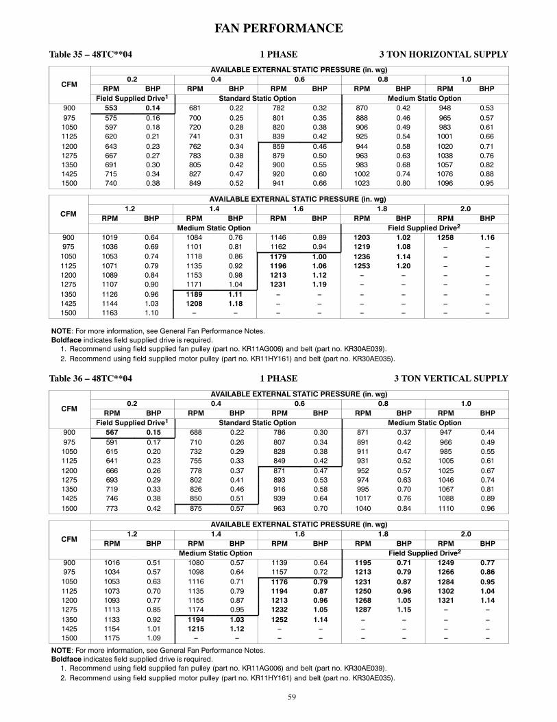
59
FAN PERFORMANCE
Table 35 – 48TC**04 1 PHASE 3 TON HORIZONTAL SUPPLY
CFM
AVAILABLE EXTERNAL STATIC PRESSURE (in. wg)0.2 0.4 0.6 0.8 1.0
RPM BHP RPM BHP RPM BHP RPM BHP RPM BHPField Supplied Drive1 Standard Static Option Medium Static Option
900 553 0.14 681 0.22 782 0.32 870 0.42 948 0.53975 575 0.16 700 0.25 801 0.35 888 0.46 965 0.571050 597 0.18 720 0.28 820 0.38 906 0.49 983 0.611125 620 0.21 741 0.31 839 0.42 925 0.54 1001 0.661200 643 0.23 762 0.34 859 0.46 944 0.58 1020 0.711275 667 0.27 783 0.38 879 0.50 963 0.63 1038 0.761350 691 0.30 805 0.42 900 0.55 983 0.68 1057 0.821425 715 0.34 827 0.47 920 0.60 1002 0.74 1076 0.881500 740 0.38 849 0.52 941 0.66 1023 0.80 1096 0.95
CFM
AVAILABLE EXTERNAL STATIC PRESSURE (in. wg)1.2 1.4 1.6 1.8 2.0
RPM BHP RPM BHP RPM BHP RPM BHP RPM BHPMedium Static Option Field Supplied Drive2
900 1019 0.64 1084 0.76 1146 0.89 1203 1.02 1258 1.16975 1036 0.69 1101 0.81 1162 0.94 1219 1.08 --- ---1050 1053 0.74 1118 0.86 1179 1.00 1236 1.14 --- ---1125 1071 0.79 1135 0.92 1196 1.06 1253 1.20 --- ---1200 1089 0.84 1153 0.98 1213 1.12 --- --- --- ---1275 1107 0.90 1171 1.04 1231 1.19 --- --- --- ---1350 1126 0.96 1189 1.11 --- --- --- --- --- ---1425 1144 1.03 1208 1.18 --- --- --- --- --- ---1500 1163 1.10 --- --- --- --- --- --- --- ---
NOTE: For more information, see General Fan Performance Notes.Boldface indicates field supplied drive is required.1. Recommend using field supplied fan pulley (part no. KR11AG006) and belt (part no. KR30AE039).2. Recommend using field supplied motor pulley (part no. KR11HY161) and belt (part no. KR30AE035).
Table 36 – 48TC**04 1 PHASE 3 TON VERTICAL SUPPLY
CFM
AVAILABLE EXTERNAL STATIC PRESSURE (in. wg)0.2 0.4 0.6 0.8 1.0
RPM BHP RPM BHP RPM BHP RPM BHP RPM BHPField Supplied Drive1 Standard Static Option Medium Static Option
900 567 0.15 688 0.22 786 0.30 871 0.37 947 0.44975 591 0.17 710 0.26 807 0.34 891 0.42 966 0.491050 615 0.20 732 0.29 828 0.38 911 0.47 985 0.551125 641 0.23 755 0.33 849 0.42 931 0.52 1005 0.611200 666 0.26 778 0.37 871 0.47 952 0.57 1025 0.671275 693 0.29 802 0.41 893 0.53 974 0.63 1046 0.741350 719 0.33 826 0.46 916 0.58 995 0.70 1067 0.811425 746 0.38 850 0.51 939 0.64 1017 0.76 1088 0.891500 773 0.42 875 0.57 963 0.70 1040 0.84 1110 0.96
CFM
AVAILABLE EXTERNAL STATIC PRESSURE (in. wg)1.2 1.4 1.6 1.8 2.0
RPM BHP RPM BHP RPM BHP RPM BHP RPM BHPMedium Static Option Field Supplied Drive2
900 1016 0.51 1080 0.57 1139 0.64 1195 0.71 1249 0.77975 1034 0.57 1098 0.64 1157 0.72 1213 0.79 1266 0.861050 1053 0.63 1116 0.71 1176 0.79 1231 0.87 1284 0.951125 1073 0.70 1135 0.79 1194 0.87 1250 0.96 1302 1.041200 1093 0.77 1155 0.87 1213 0.96 1268 1.05 1321 1.141275 1113 0.85 1174 0.95 1232 1.05 1287 1.15 --- ---1350 1133 0.92 1194 1.03 1252 1.14 --- --- --- ---1425 1154 1.01 1215 1.12 --- --- --- --- --- ---1500 1175 1.09 --- --- --- --- --- --- --- ---
NOTE: For more information, see General Fan Performance Notes.Boldface indicates field supplied drive is required.1. Recommend using field supplied fan pulley (part no. KR11AG006) and belt (part no. KR30AE039).2. Recommend using field supplied motor pulley (part no. KR11HY161) and belt (part no. KR30AE035).

60
FAN PERFORMANCE (cont.)Table 37 – 48TC**04 3 PHASE 3 TON HORIZONTAL SUPPLY
CFM
AVAILABLE EXTERNAL STATIC PRESSURE (in. wg)0.2 0.4 0.6 0.8 1.0
RPM BHP RPM BHP RPM BHP RPM BHP RPM BHPField Supplied Drive1 Standard Static Option Medium Static Option
900 553 0.14 681 0.22 782 0.32 870 0.42 948 0.53975 575 0.16 700 0.25 801 0.35 888 0.46 965 0.571050 597 0.18 720 0.28 820 0.38 906 0.49 983 0.611125 620 0.21 741 0.31 839 0.42 925 0.54 1001 0.661200 643 0.23 762 0.34 859 0.46 944 0.58 1020 0.711275 667 0.27 783 0.38 879 0.50 963 0.63 1038 0.761350 691 0.30 805 0.42 900 0.55 983 0.68 1057 0.821425 715 0.34 827 0.47 920 0.60 1002 0.74 1076 0.881500 740 0.38 849 0.52 941 0.66 1023 0.80 1096 0.95
CFM
AVAILABLE EXTERNAL STATIC PRESSURE (in. wg)1.2 1.4 1.6 1.8 2.0
RPM BHP RPM BHP RPM BHP RPM BHP RPM BHPMedium Static Option High Static Option
900 1019 0.64 1084 0.76 1146 0.89 1203 1.02 1258 1.16975 1036 0.69 1101 0.81 1162 0.94 1219 1.08 1274 1.221050 1053 0.74 1118 0.86 1179 1.00 1236 1.14 1290 1.281125 1071 0.79 1135 0.92 1196 1.06 1253 1.20 1307 1.351200 1089 0.84 1153 0.98 1213 1.12 1270 1.27 1324 1.421275 1107 0.90 1171 1.04 1231 1.19 1287 1.34 1341 1.501350 1126 0.96 1189 1.11 1249 1.26 1305 1.42 1358 1.581425 1144 1.03 1208 1.18 1267 1.34 1323 1.50 1376 1.661500 1163 1.10 1226 1.25 1285 1.41 1341 1.58 1394 1.75
NOTE: For more information, see General Fan Performance Notes.1. Recommend using field supplied drive (part no. KR11AG006) and belt (part no. KR30AE039)
Table 38 – 48TC**04 3 PHASE 3 TON VERTICAL SUPPLY
CFM
AVAILABLE EXTERNAL STATIC PRESSURE (in. wg)0.2 0.4 0.6 0.8 1.0
RPM BHP RPM BHP RPM BHP RPM BHP RPM BHPField Supplied Drive1 Standard Static Option Medium Static Option
900 567 0.15 688 0.22 786 0.30 871 0.37 947 0.44975 591 0.17 710 0.26 807 0.34 891 0.42 966 0.491050 615 0.20 732 0.29 828 0.38 911 0.47 985 0.551125 641 0.23 755 0.33 849 0.42 931 0.52 1005 0.611200 666 0.26 778 0.37 871 0.47 952 0.57 1025 0.671275 693 0.29 802 0.41 893 0.53 974 0.63 1046 0.741350 719 0.33 826 0.46 916 0.58 995 0.70 1067 0.811425 746 0.38 850 0.51 939 0.64 1017 0.76 1088 0.891500 773 0.42 875 0.57 963 0.70 1040 0.84 1110 0.96
CFM
AVAILABLE EXTERNAL STATIC PRESSURE (in. wg)1.2 1.4 1.6 1.8 2.0
RPM BHP RPM BHP RPM BHP RPM BHP RPM BHPMedium Static Option High Static Option
900 1016 0.51 1080 0.57 1139 0.64 1195 0.71 1249 0.77975 1034 0.57 1098 0.64 1157 0.72 1213 0.79 1266 0.861050 1053 0.63 1116 0.71 1176 0.79 1231 0.87 1284 0.951125 1073 0.70 1135 0.79 1194 0.87 1250 0.96 1302 1.041200 1093 0.77 1155 0.87 1213 0.96 1268 1.05 1321 1.141275 1113 0.85 1174 0.95 1232 1.05 1287 1.15 1339 1.251350 1133 0.92 1194 1.03 1252 1.14 1307 1.25 1358 1.351425 1154 1.01 1215 1.12 1272 1.24 1326 1.35 1378 1.461500 1175 1.09 1235 1.22 1292 1.34 1346 1.46 1397 1.58
NOTE: For more information, see General Fan Performance Notes.Boldface indicates field supplied drive is required.1. Recommend using field supplied fan pulley (part no. KR11AG006) and belt (part no. KR30AE039).

61
FAN PERFORMANCE (cont.)Table 39 – 48TC**05 1 PHASE 4 TON HORIZONTAL SUPPLY
CFM
AVAILABLE EXTERNAL STATIC PRESSURE (in. wg)0.2 0.4 0.6 0.8 1.0
RPM BHP RPM BHP RPM BHP RPM BHP RPM BHPStandard Static Option Medium Static Option
1200 643 0.23 762 0.34 859 0.46 944 0.58 1020 0.711300 675 0.28 790 0.40 886 0.52 969 0.65 1044 0.781400 707 0.33 819 0.45 913 0.58 996 0.72 1070 0.861500 740 0.38 849 0.52 941 0.66 1023 0.80 1096 0.951600 773 0.45 879 0.59 970 0.73 1050 0.88 1123 1.041700 807 0.52 910 0.67 999 0.82 1078 0.98 1150 1.141800 841 0.59 942 0.75 1029 0.91 1106 1.08 1177 1.251900 875 0.68 974 0.85 1059 1.02 1135 1.19 1205 1.372000 910 0.77 1006 0.95 1090 1.13 1165 1.31 1234 1.49
CFM
AVAILABLE EXTERNAL STATIC PRESSURE (in. wg)1.2 1.4 1.6 1.8 2.0
RPM BHP RPM BHP RPM BHP RPM BHP RPM BHPMedium Static Option Field Supplied Drive1
1200 1089 0.84 1153 0.98 1213 1.12 --- --- --- ---1300 1113 0.92 1177 1.06 --- --- --- --- --- ---1400 1138 1.01 1201 1.15 --- --- --- --- --- ---1500 1163 1.10 --- --- --- --- --- --- --- ---1600 1189 1.20 --- --- --- --- --- --- --- ---1700 --- --- --- --- --- --- --- --- --- ---1800 --- --- --- --- --- --- --- --- --- ---1900 --- --- --- --- --- --- --- --- --- ---2000 --- --- --- --- --- --- --- --- --- ---
NOTE: For more information, see General Fan Performance Notes.Boldface indicates field supplied drive is required.1. Recommend using field supplied motor pulley (part no. KR11HY161) and belt (part no. KR30AE035).
Table 40 – 48TC**05 1 PHASE 4 TON VERTICAL SUPPLY
CFM
AVAILABLE EXTERNAL STATIC PRESSURE (in. wg)0.2 0.4 0.6 0.8 1.0
RPM BHP RPM BHP RPM BHP RPM BHP RPM BHPStandard Static Option Medium Static Option
1200 666 0.26 778 0.37 871 0.47 952 0.57 1025 0.671300 701 0.31 810 0.43 901 0.54 981 0.65 1053 0.761400 737 0.36 842 0.49 931 0.62 1010 0.74 1081 0.861500 773 0.42 875 0.57 963 0.70 1040 0.84 1110 0.961600 810 0.49 909 0.65 994 0.79 1070 0.94 1140 1.081700 847 0.57 943 0.73 1027 0.89 1101 1.05 1170 1.201800 885 0.66 978 0.83 1060 1.00 1133 1.16 1200 1.321900 923 0.75 1014 0.94 1093 1.11 1165 1.29 1231 1.462000 962 0.85 1049 1.05 1127 1.24 1198 1.42 1263 1.61
CFM
AVAILABLE EXTERNAL STATIC PRESSURE (in. wg)1.2 1.4 1.6 1.8 2.0
RPM BHP RPM BHP RPM BHP RPM BHP RPM BHPMedium Static Option Field Supplied Drive1
1200 1093 0.77 1155 0.87 1213 0.96 1268 1.05 1321 1.141300 1119 0.87 1181 0.98 1239 1.08 1294 1.18 --- ---1400 1147 0.98 1208 1.09 --- --- --- --- --- ---1500 1175 1.09 --- --- --- --- --- --- --- ---1600 --- --- --- --- --- --- --- --- --- ---1700 --- --- --- --- --- --- --- --- --- ---1800 --- --- --- --- --- --- --- --- --- ---1900 --- --- --- --- --- --- --- --- --- ---2000 --- --- --- --- --- --- --- --- --- ---
NOTE: For more information, see General Fan Performance Notes.Boldface indicates field supplied drive is required.1. Recommend using field supplied motor pulley (part no. KR11HY161) and belt (part no. KR30AE035).

62
FAN PERFORMANCE (cont.)Table 41 – 48TC**05 3 PHASE 4 TON HORIZONTAL SUPPLY
CFM
AVAILABLE EXTERNAL STATIC PRESSURE (in. wg)0.2 0.4 0.6 0.8 1.0
RPM BHP RPM BHP RPM BHP RPM BHP RPM BHPStandard Static Option Medium Static Option
1200 643 0.23 762 0.34 859 0.46 944 0.58 1020 0.711300 675 0.28 790 0.40 886 0.52 969 0.65 1044 0.781400 707 0.33 819 0.45 913 0.58 996 0.72 1070 0.861500 740 0.38 849 0.52 941 0.66 1023 0.80 1096 0.951600 773 0.45 879 0.59 970 0.73 1050 0.88 1123 1.041700 807 0.52 910 0.67 999 0.82 1078 0.98 1150 1.141800 841 0.59 942 0.75 1029 0.91 1106 1.08 1177 1.251900 875 0.68 974 0.85 1059 1.02 1135 1.19 1205 1.372000 910 0.77 1006 0.95 1090 1.13 1165 1.31 1234 1.49
CFM
AVAILABLE EXTERNAL STATIC PRESSURE (in. wg)1.2 1.4 1.6 1.8 2.0
RPM BHP RPM BHP RPM BHP RPM BHP RPM BHPMedium Static Option High Static Option
1200 1089 0.84 1153 0.98 1213 1.12 1270 1.27 1324 1.421300 1113 0.92 1177 1.06 1237 1.21 1293 1.36 1347 1.521400 1138 1.01 1201 1.15 1261 1.31 1317 1.47 1370 1.631500 1163 1.10 1226 1.25 1285 1.41 1341 1.58 1394 1.751600 1189 1.20 1252 1.36 1310 1.53 1365 1.70 1418 1.871700 1216 1.31 1277 1.48 1335 1.65 1390 1.83 1442 2.011800 1242 1.42 1303 1.60 1361 1.78 1415 1.96 1467 2.151900 1270 1.55 1330 1.73 1387 1.92 1441 2.11 1493 2.302000 1297 1.68 1357 1.87 1414 2.07 1467 2.26 --- ---
NOTE: For more information, see General Fan Performance Notes.Boldface indicates field supplied drive is required.1. Recommend using field supplied fan pulley (part no. KR11AZ506), motor pulley (part no. KR11HY181) and belt (part no. KR30AE041).
Table 42 – 48TC**05 3 PHASE 4 TON VERTICAL SUPPLY
CFM
AVAILABLE EXTERNAL STATIC PRESSURE (in. wg)0.2 0.4 0.6 0.8 1.0
RPM BHP RPM BHP RPM BHP RPM BHP RPM BHPStandard Static Option Medium Static Option
1200 666 0.26 778 0.37 871 0.47 952 0.57 1025 0.671300 701 0.31 810 0.43 901 0.54 981 0.65 1053 0.761400 737 0.36 842 0.49 931 0.62 1010 0.74 1081 0.861500 773 0.42 875 0.57 963 0.70 1040 0.84 1110 0.961600 810 0.49 909 0.65 994 0.79 1070 0.94 1140 1.081700 847 0.57 943 0.73 1027 0.89 1101 1.05 1170 1.201800 885 0.66 978 0.83 1060 1.00 1133 1.16 1200 1.321900 923 0.75 1014 0.94 1093 1.11 1165 1.29 1231 1.462000 962 0.85 1049 1.05 1127 1.24 1198 1.42 1263 1.61
CFM
AVAILABLE EXTERNAL STATIC PRESSURE (in. wg)1.2 1.4 1.6 1.8 2.0
RPM BHP RPM BHP RPM BHP RPM BHP RPM BHPMedium Static Option High Static Option
1200 1093 0.77 1155 0.87 1213 0.96 1268 1.05 1321 1.141300 1119 0.87 1181 0.98 1239 1.08 1294 1.18 1346 1.281400 1147 0.98 1208 1.09 1265 1.21 1320 1.32 1371 1.431500 1175 1.09 1235 1.22 1292 1.34 1346 1.46 1397 1.581600 1204 1.21 1263 1.35 1320 1.48 1373 1.61 1424 1.741700 1233 1.34 1292 1.49 1348 1.63 1401 1.77 1451 1.911800 1262 1.48 1321 1.64 1376 1.79 1428 1.94 1479 2.091900 1293 1.63 1350 1.79 1405 1.96 1457 2.12 1506 2.282000 1323 1.79 1380 1.96 1434 2.13 1486 2.31 --- ---
NOTE: For more information, see General Fan Performance Notes.Boldface indicates field supplied drive is required.1. Recommend using field supplied fan pulley (part no. KR11AZ506), motor pulley (part no. KR11HY181) and belt (part no. KR30AE041).

63
FAN PERFORMANCE (cont.)Table 43 – 48TC**06 1 PHASE 5 TON HORIZONTAL SUPPLY
CFM
AVAILABLE EXTERNAL STATIC PRESSURE (in. wg)0.2 0.4 0.6 0.8 1.0
RPM BHP RPM BHP RPM BHP RPM BHP RPM BHPStandard Static Option
1500 800 0.39 904 0.49 999 0.60 1087 0.72 1169 0.851625 849 0.48 947 0.59 1038 0.70 1122 0.83 1201 0.961750 899 0.59 992 0.70 1078 0.82 1159 0.95 1235 1.081875 950 0.70 1038 0.82 1120 0.95 1198 1.08 1271 1.222000 1001 0.84 1085 0.96 1163 1.09 1238 1.23 1309 1.382125 1053 0.99 1133 1.12 1208 1.26 1280 1.40 --- ---2250 1106 1.16 1182 1.29 1254 1.44 --- --- --- ---2375 1159 1.34 1231 1.49 --- --- --- --- --- ---2500 --- --- --- --- --- --- --- --- --- ---
CFM
AVAILABLE EXTERNAL STATIC PRESSURE (in. wg)1.2 1.4 1.6 1.8 2.0
RPM BHP RPM BHP RPM BHP RPM BHP RPM BHPMedium Static Option
1500 1247 0.98 1320 1.13 1390 1.28 1457 1.44 --- ---1625 1276 1.10 1348 1.24 1416 1.40 --- --- --- ---1750 1308 1.22 1377 1.38 --- --- --- --- --- ---1875 1342 1.37 --- --- --- --- --- --- --- ---2000 --- --- --- --- --- --- --- --- --- ---2125 --- --- --- --- --- --- --- --- --- ---2250 --- --- --- --- --- --- --- --- --- ---2375 --- --- --- --- --- --- --- --- --- ---2500 --- --- --- --- --- --- --- --- --- ---
NOTE: For more information, see General Fan Performance Notes.
Table 44 – 48TC**06 1 PHASE 5 TON VERTICAL SUPPLY
CFM
AVAILABLE EXTERNAL STATIC PRESSURE (in. wg)0.2 0.4 0.6 0.8 1.0
RPM BHP RPM BHP RPM BHP RPM BHP RPM BHPStandard Static Option Medium Static Option
1500 848 0.42 968 0.55 1069 0.68 1158 0.80 1238 0.941625 897 0.51 1013 0.65 1111 0.79 1198 0.93 1277 1.071750 947 0.61 1059 0.76 1155 0.91 1240 1.06 1318 1.211875 997 0.72 1105 0.89 1199 1.05 1283 1.21 1359 1.372000 1048 0.85 1153 1.03 1244 1.20 1326 1.37 --- ---2125 1100 1.00 1201 1.19 1290 1.37 --- --- --- ---2250 1152 1.16 1250 1.36 --- --- --- --- --- ---2375 1205 1.34 --- --- --- --- --- --- --- ---2500 --- --- --- --- --- --- --- --- --- ---
CFM
AVAILABLE EXTERNAL STATIC PRESSURE (in. wg)1.2 1.4 1.6 1.8 2.0
RPM BHP RPM BHP RPM BHP RPM BHP RPM BHPMedium Static Option Field---Supplied Drive1
1500 1312 1.07 1380 1.20 1445 1.34 1506 1.48 --- ---1625 1350 1.21 1418 1.35 1482 1.50 --- --- --- ---1750 1390 1.36 --- --- --- --- --- --- --- ---1875 --- --- --- --- --- --- --- --- --- ---2000 --- --- --- --- --- --- --- --- --- ---2125 --- --- --- --- --- --- --- --- --- ---2250 --- --- --- --- --- --- --- --- --- ---2375 --- --- --- --- --- --- --- --- --- ---2500 --- --- --- --- --- --- --- --- --- ---
NOTE: For more information, see General Fan Performance Notes.Boldface indicates field supplied drive is required.1. Recommend using field supplied motor pulley (part no. KR11HY171) and belt (part no. KR30AE039).

64
FAN PERFORMANCE (cont.)Table 45 – 48TC**06 3 PHASE 5 TON HORIZONTAL SUPPLY
CFM
AVAILABLE EXTERNAL STATIC PRESSURE (in. wg)0.2 0.4 0.6 0.8 1.0
RPM BHP RPM BHP RPM BHP RPM BHP RPM BHPStandard Static Option
1500 800 0.39 904 0.49 999 0.60 1087 0.72 1169 0.851625 849 0.48 947 0.59 1038 0.70 1122 0.83 1201 0.961750 899 0.59 992 0.70 1078 0.82 1159 0.95 1235 1.081875 950 0.70 1038 0.82 1120 0.95 1198 1.08 1271 1.222000 1001 0.84 1085 0.96 1163 1.09 1238 1.23 1309 1.382125 1053 0.99 1133 1.12 1208 1.26 1280 1.40 1348 1.552250 1106 1.16 1182 1.29 1254 1.44 1323 1.59 1389 1.742375 1159 1.34 1231 1.49 1300 1.64 1367 1.80 1430 1.962500 1212 1.55 1281 1.70 1348 1.86 1412 2.02 1473 2.19
CFM
AVAILABLE EXTERNAL STATIC PRESSURE (in. wg)1.2 1.4 1.6 1.8 2.0
RPM BHP RPM BHP RPM BHP RPM BHP RPM BHPMedium Static Option High Static Option
1500 1247 0.98 1320 1.13 1390 1.28 1457 1.44 1522 1.611625 1276 1.10 1348 1.24 1416 1.40 1481 1.56 1544 1.731750 1308 1.22 1377 1.38 1444 1.53 1507 1.70 1569 1.871875 1342 1.37 1409 1.52 1473 1.69 1536 1.86 1596 2.032000 1377 1.53 1442 1.69 1505 1.86 1565 2.03 1624 2.212125 1414 1.71 1477 1.87 1538 2.04 1597 2.22 1654 2.402250 1452 1.91 1514 2.08 1573 2.25 1630 2.43 1686 2.622375 1492 2.12 1551 2.30 1609 2.48 1665 2.66 1719 2.852500 1533 2.36 1591 2.54 1647 2.73 --- --- --- ---
NOTE: For more information, see General Fan Performance Notes.Boldface indicates field supplied drive is required.1. Recommend using field supplied fan pulley (part no. KR11AZ506), motor pulley (part no. KR11HY191) and belt (part no. KR30AE042).
Table 46 – 48TC**06 3 PHASE 5 TON VERTICAL SUPPLY
CFM
AVAILABLE EXTERNAL STATIC PRESSURE (in. wg)0.2 0.4 0.6 0.8 1.0
RPM BHP RPM BHP RPM BHP RPM BHP RPM BHPStandard Static Option Medium Static Option
1500 848 0.42 968 0.55 1069 0.68 1158 0.80 1238 0.941625 897 0.51 1013 0.65 1111 0.79 1198 0.93 1277 1.071750 947 0.61 1059 0.76 1155 0.91 1240 1.06 1318 1.211875 997 0.72 1105 0.89 1199 1.05 1283 1.21 1359 1.372000 1048 0.85 1153 1.03 1244 1.20 1326 1.37 1401 1.542125 1100 1.00 1201 1.19 1290 1.37 1370 1.55 1444 1.732250 1152 1.16 1250 1.36 1336 1.55 1415 1.75 1487 1.942375 1205 1.34 1299 1.55 1384 1.76 1460 1.96 1532 2.172500 1258 1.54 1349 1.76 1431 1.98 1506 2.20 1576 2.41
CFM
AVAILABLE EXTERNAL STATIC PRESSURE (in. wg)1.2 1.4 1.6 1.8 2.0
RPM BHP RPM BHP RPM BHP RPM BHP RPM BHPMedium Static Option High Static Option
1500 1312 1.07 1380 1.20 1445 1.34 1506 1.48 1564 1.621625 1350 1.21 1418 1.35 1482 1.50 1542 1.64 1600 1.791750 1390 1.36 1457 1.51 1520 1.67 1580 1.83 1637 1.981875 1430 1.53 1496 1.69 1559 1.86 1618 2.02 1675 2.192000 1471 1.72 1536 1.89 1598 2.06 1657 2.24 1713 2.412125 1513 1.92 1577 2.10 1638 2.28 1696 2.47 1752 2.652250 1555 2.13 1619 2.33 1679 2.52 1736 2.72 --- ---2375 1598 2.37 1661 2.57 1720 2.78 --- --- --- ---2500 1642 2.63 1704 2.84 --- --- --- --- --- ---
NOTE: For more information, see General Fan Performance Notes.Boldface indicates field supplied drive is required.1. Recommend using field supplied fan pulley (part no. KR11AZ506), motor pulley (part no. KR11HY191) and belt (part no. KR30AE042).
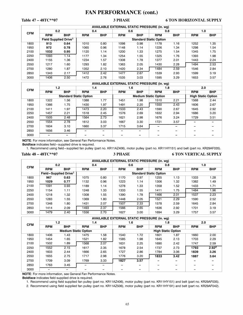
65
FAN PERFORMANCE (cont.)Table 47 – 48TC**07 3 PHASE 6 TON HORIZONTAL SUPPLY
CFM
AVAILABLE EXTERNAL STATIC PRESSURE (in. wg)0.2 0.4 0.6 0.8 1.0
RPM BHP RPM BHP RPM BHP RPM BHP RPM BHPField Supplied Drive1 Standard Static Option
1800 913 0.64 1010 0.80 1098 0.98 1178 1.16 1252 1.351950 972 0.78 1065 0.96 1148 1.14 1226 1.34 1298 1.542100 1032 0.95 1120 1.14 1200 1.33 1275 1.54 1345 1.752250 1093 1.14 1177 1.34 1254 1.55 1325 1.76 1393 1.982400 1155 1.36 1234 1.57 1308 1.78 1377 2.01 1443 2.242550 1217 1.60 1293 1.82 1363 2.05 1430 2.28 1494 2.532700 1280 1.87 1352 2.10 1420 2.34 1484 2.59 1546 2.842850 1343 2.17 1412 2.42 1477 2.67 1539 2.93 1599 3.193000 1406 2.50 1472 2.76 1535 3.03 1595 3.29 1653 3.57
CFM
AVAILABLE EXTERNAL STATIC PRESSURE (in. wg)1.2 1.4 1.6 1.8 2.0
RPM BHP RPM BHP RPM BHP RPM BHP RPM BHPStandard Static Option Medium Static Option High Static Option
1800 1322 1.56 1388 1.77 1451 1.98 1510 2.21 1568 2.441950 1366 1.75 1430 1.97 1491 2.20 1550 2.43 1606 2.672100 1411 1.97 1473 2.20 1533 2.43 1590 2.67 1645 2.922250 1457 2.21 1518 2.45 1576 2.69 1632 2.94 1686 3.202400 1505 2.48 1564 2.73 1621 2.98 1676 3.24 1729 3.512550 1554 2.78 1612 3.03 1667 3.30 1721 3.57 --- ---2700 1604 3.10 1660 3.37 1715 3.64 --- --- --- ---2850 1656 3.46 --- --- --- --- --- --- --- ---3000 --- --- --- --- --- --- --- --- --- ---
NOTE: For more information, see General Fan Performance Notes.Boldface indicates field---supplied drive is required.1. Recommend using field---supplied fan pulley (part no. KR11AZ406), motor pulley (part no. KR11HY151) and belt (part no. KR29AF035).
Table 48 – 48TC**07 3 PHASE 6 TON VERTICAL SUPPLY
CFM
AVAILABLE EXTERNAL STATIC PRESSURE (in. wg)0.2 0.4 0.6 0.8 1.0
RPM BHP RPM BHP RPM BHP RPM BHP RPM BHPField---Supplied Drive1 Standard Static Option
1800 967 0.63 1075 0.80 1170 0.97 1255 1.13 1333 1.281950 1029 0.77 1132 0.96 1223 1.14 1306 1.32 1382 1.492100 1091 0.93 1189 1.14 1278 1.33 1358 1.52 1433 1.712250 1154 1.11 1248 1.33 1333 1.55 1411 1.75 1484 1.962400 1218 1.32 1308 1.55 1390 1.78 1466 2.01 1537 2.232550 1283 1.55 1369 1.80 1448 2.05 1521 2.29 1590 2.522700 1348 1.80 1431 2.07 1507 2.33 1578 2.59 1645 2.842850 1414 2.09 1493 2.37 1566 2.65 1636 2.92 1701 3.193000 1479 2.40 1556 2.70 1627 3.00 1694 3.29 1757 3.57
CFM
AVAILABLE EXTERNAL STATIC PRESSURE (in. wg)1.2 1.4 1.6 1.8 2.0
RPM BHP RPM BHP RPM BHP RPM BHP RPM BHPMedium Static Option High Static Option
1800 1406 1.43 1475 1.58 1540 1.72 1601 1.87 1660 2.001950 1454 1.65 1521 1.82 1585 1.98 1645 2.13 1703 2.292100 1502 1.89 1568 2.07 1631 2.25 1690 2.42 1747 2.592250 1552 2.15 1617 2.35 1678 2.54 1737 2.73 1793 2.9222400 1603 2.44 1666 2.65 1727 2.86 1784 3.06 1839 3.262550 1655 2.75 1717 2.98 1776 3.20 1833 3.42 1887 3.642700 1709 3.09 1769 3.33 1827 3.57 --- --- --- ---2850 1763 3.45 --- --- --- --- --- --- --- ---3000 --- --- --- --- --- --- --- --- --- ---
NOTE: For more information, see General Fan Performance Notes.Boldface indicates field supplied drive is required.1. Recommend using field supplied fan pulley (part no. KR11AZ406), motor pulley (part no. KR11HY151) and belt (part no. KR29AF035).2. Recommend using field supplied fan pulley (part no. KR11AZ506), motor pulley (part no. KR11HY191) and belt (part no. KR29AF042).
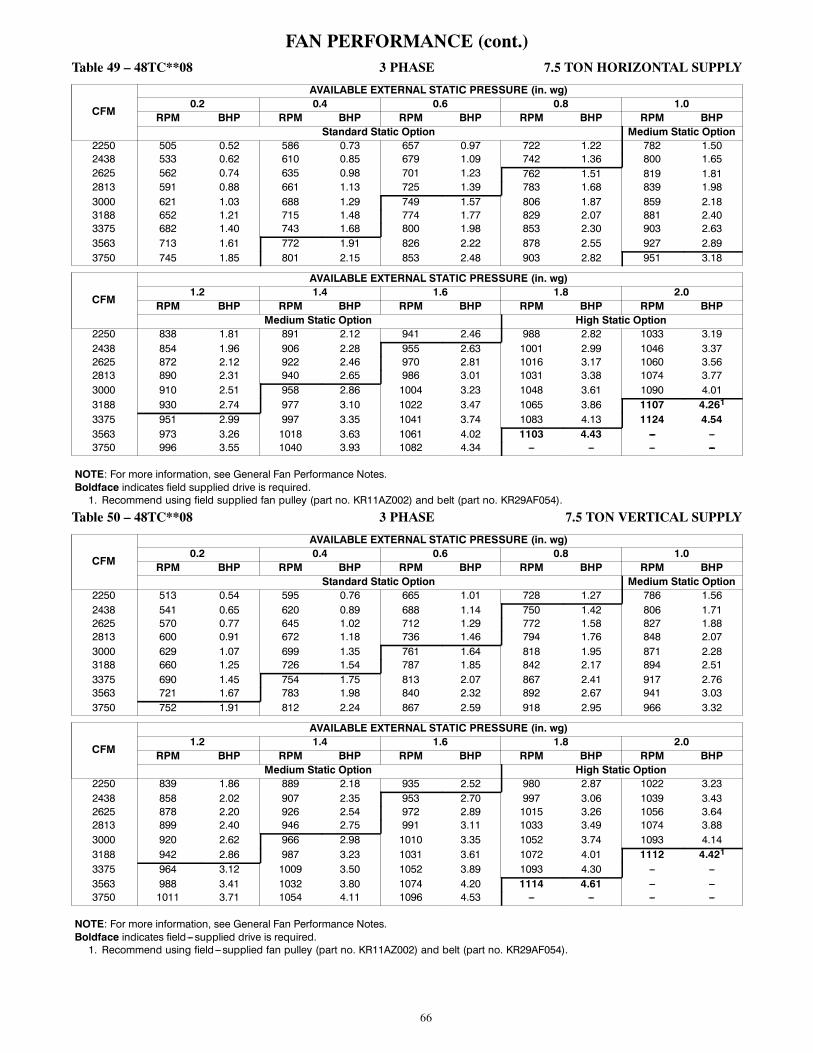
66
FAN PERFORMANCE (cont.)Table 49 – 48TC**08 3 PHASE 7.5 TON HORIZONTAL SUPPLY
CFM
AVAILABLE EXTERNAL STATIC PRESSURE (in. wg)0.2 0.4 0.6 0.8 1.0
RPM BHP RPM BHP RPM BHP RPM BHP RPM BHPStandard Static Option Medium Static Option
2250 505 0.52 586 0.73 657 0.97 722 1.22 782 1.502438 533 0.62 610 0.85 679 1.09 742 1.36 800 1.652625 562 0.74 635 0.98 701 1.23 762 1.51 819 1.812813 591 0.88 661 1.13 725 1.39 783 1.68 839 1.983000 621 1.03 688 1.29 749 1.57 806 1.87 859 2.183188 652 1.21 715 1.48 774 1.77 829 2.07 881 2.403375 682 1.40 743 1.68 800 1.98 853 2.30 903 2.633563 713 1.61 772 1.91 826 2.22 878 2.55 927 2.893750 745 1.85 801 2.15 853 2.48 903 2.82 951 3.18
CFM
AVAILABLE EXTERNAL STATIC PRESSURE (in. wg)1.2 1.4 1.6 1.8 2.0
RPM BHP RPM BHP RPM BHP RPM BHP RPM BHPMedium Static Option High Static Option
2250 838 1.81 891 2.12 941 2.46 988 2.82 1033 3.192438 854 1.96 906 2.28 955 2.63 1001 2.99 1046 3.372625 872 2.12 922 2.46 970 2.81 1016 3.17 1060 3.562813 890 2.31 940 2.65 986 3.01 1031 3.38 1074 3.773000 910 2.51 958 2.86 1004 3.23 1048 3.61 1090 4.013188 930 2.74 977 3.10 1022 3.47 1065 3.86 1107 4.261
3375 951 2.99 997 3.35 1041 3.74 1083 4.13 1124 4.543563 973 3.26 1018 3.63 1061 4.02 1103 4.43 --- ---3750 996 3.55 1040 3.93 1082 4.34 --- --- --- ---
NOTE: For more information, see General Fan Performance Notes.Boldface indicates field supplied drive is required.1. Recommend using field supplied fan pulley (part no. KR11AZ002) and belt (part no. KR29AF054).
Table 50 – 48TC**08 3 PHASE 7.5 TON VERTICAL SUPPLY
CFM
AVAILABLE EXTERNAL STATIC PRESSURE (in. wg)0.2 0.4 0.6 0.8 1.0
RPM BHP RPM BHP RPM BHP RPM BHP RPM BHPStandard Static Option Medium Static Option
2250 513 0.54 595 0.76 665 1.01 728 1.27 786 1.562438 541 0.65 620 0.89 688 1.14 750 1.42 806 1.712625 570 0.77 645 1.02 712 1.29 772 1.58 827 1.882813 600 0.91 672 1.18 736 1.46 794 1.76 848 2.073000 629 1.07 699 1.35 761 1.64 818 1.95 871 2.283188 660 1.25 726 1.54 787 1.85 842 2.17 894 2.513375 690 1.45 754 1.75 813 2.07 867 2.41 917 2.763563 721 1.67 783 1.98 840 2.32 892 2.67 941 3.033750 752 1.91 812 2.24 867 2.59 918 2.95 966 3.32
CFM
AVAILABLE EXTERNAL STATIC PRESSURE (in. wg)1.2 1.4 1.6 1.8 2.0
RPM BHP RPM BHP RPM BHP RPM BHP RPM BHPMedium Static Option High Static Option
2250 839 1.86 889 2.18 935 2.52 980 2.87 1022 3.232438 858 2.02 907 2.35 953 2.70 997 3.06 1039 3.432625 878 2.20 926 2.54 972 2.89 1015 3.26 1056 3.642813 899 2.40 946 2.75 991 3.11 1033 3.49 1074 3.883000 920 2.62 966 2.98 1010 3.35 1052 3.74 1093 4.143188 942 2.86 987 3.23 1031 3.61 1072 4.01 1112 4.421
3375 964 3.12 1009 3.50 1052 3.89 1093 4.30 --- ---3563 988 3.41 1032 3.80 1074 4.20 1114 4.61 --- ---3750 1011 3.71 1054 4.11 1096 4.53 --- --- --- ---
NOTE: For more information, see General Fan Performance Notes.Boldface indicates field---supplied drive is required.1. Recommend using field---supplied fan pulley (part no. KR11AZ002) and belt (part no. KR29AF054).

67
FAN PERFORMANCE (cont.)Table 51 – 48TC**09 3 PHASE 8.5 TON HORIZONTAL SUPPLY
CFM
AVAILABLE EXTERNAL STATIC PRESSURE (in. wg)0.2 0.4 0.6 0.8 1.0
RPM BHP RPM BHP RPM BHP RPM BHP RPM BHPField---Supplied Drive1 Standard Static Option Medium Static Option
2550 497 0.48 579 0.61 651 0.75 717 0.90 777 1.052763 524 0.58 602 0.72 671 0.87 735 1.03 794 1.192975 551 0.70 626 0.86 693 1.01 754 1.18 812 1.353188 580 0.84 651 1.00 716 1.17 775 1.34 831 1.523400 609 1.00 677 1.17 739 1.35 797 1.53 851 1.713613 638 1.17 703 1.35 763 1.54 819 1.73 871 1.933825 668 1.37 730 1.56 788 1.76 842 1.96 893 2.164038 698 1.59 758 1.79 813 2.00 866 2.20 915 2.424250 728 1.83 786 2.04 839 2.26 890 2.47 938 2.70
CFM
AVAILABLE EXTERNAL STATIC PRESSURE (in. wg)1.2 1.4 1.6 1.8 2.0
RPM BHP RPM BHP RPM BHP RPM BHP RPM BHPMedium Static Option High Static Option
2550 833 1.21 886 1.38 936 1.56 984 1.74 1029 1.932763 849 1.36 900 1.53 950 1.72 996 1.90 1041 2.102975 865 1.52 916 1.70 964 1.89 1010 2.09 1054 2.293188 883 1.70 933 1.89 980 2.09 1025 2.29 1068 2.503400 902 1.90 950 2.10 996 2.30 1041 2.51 1083 2.733613 921 2.13 969 2.33 1014 2.54 1057 2.76 1099 2.982
3825 941 2.37 988 2.58 1032 2.80 1075 3.02 1116 3.254038 963 2.63 1008 2.86 1051 3.08 1093 3.31 1133 3.554250 984 2.92 1029 3.15 1071 3.39 1112 3.63 1152 3.87
NOTE: For more information, see General Fan Performance Notes.Boldface indicates field---supplied drive is required.1. Recommend using field---supplied fan pulley (part no. KR11AK012) and belt (part no. KR29AF055).2. Recommend using field---supplied motor pulley (part no. KR11HY310), fan pulley (part no. KR11AZ002) and belt (part no. KR29AF054).
Table 52 – 48TC**09 3 PHASE 8.5 TON VERTICAL SUPPLY
CFM
AVAILABLE EXTERNAL STATIC PRESSURE (in. wg)0.2 0.4 0.6 0.8 1.0
RPM BHP RPM BHP RPM BHP RPM BHP RPM BHPStandard Static Option Medium Static Option
2550 526 0.51 600 0.65 666 0.79 727 0.93 783 1.072763 557 0.62 627 0.77 690 0.92 749 1.08 804 1.232975 588 0.75 655 0.91 716 1.08 772 1.24 825 1.403188 621 0.90 684 1.07 743 1.25 797 1.42 848 1.603400 653 1.06 714 1.25 770 1.44 822 1.62 872 1.813613 687 1.25 744 1.45 798 1.65 849 1.84 897 2.043825 720 1.45 775 1.67 827 1.88 876 2.09 922 2.304038 754 1.69 807 1.91 856 2.13 904 2.35 949 2.574250 788 1.94 839 2.17 886 2.41 932 2.64 976 2.88
CFM
AVAILABLE EXTERNAL STATIC PRESSURE (in. wg)1.2 1.4 1.6 1.8 2.0
RPM BHP RPM BHP RPM BHP RPM BHP RPM BHPMedium Static Option High Static Option
2550 836 1.20 886 1.34 934 1.48 979 1.61 1022 1.742763 855 1.37 904 1.52 950 1.67 995 1.82 1037 1.972975 875 1.56 923 1.72 968 1.88 1012 2.04 1053 2.203188 897 1.77 943 1.94 987 2.11 1030 2.29 1071 2.463400 919 1.99 964 2.18 1007 2.36 1049 2.55 1089 2.731
3613 943 2.24 986 2.44 1029 2.63 1069 2.83 1108 3.023825 967 2.51 1010 2.71 1051 2.92 1090 3.13 1129 3.344038 992 2.80 1034 3.02 1074 3.24 1112 3.46 1150 3.684250 1018 3.11 1058 3.34 1097 3.57 --- --- --- ---
NOTE: For more information, see General Fan Performance Notes.Boldface indicates field supplied drive is required.1. Recommend using field supplied motor pulley (part no. KR11HY310), fan pulley (part no. KR11AZ002) and belt (part no. KR29AF054).

68
FAN PERFORMANCE (cont.)Table 53 – 48TC**12 3 PHASE 10 TON HORIZONTAL SUPPLY
CFM
AVAILABLE EXTERNAL STATIC PRESSURE (in. wg)0.2 0.4 0.6 0.8 1.0
RPM BHP RPM BHP RPM BHP RPM BHP RPM BHPField Supplied Drive1 Standard Static Option Medium Static Option
3000 579 0.70 660 0.89 732 1.09 799 1.29 860 1.503250 613 0.85 690 1.06 760 1.27 823 1.49 883 1.713500 648 1.03 721 1.25 788 1.48 850 1.71 907 1.953750 683 1.23 753 1.47 817 1.71 877 1.96 933 2.214000 719 1.45 786 1.71 848 1.97 905 2.23 959 2.504250 756 1.71 819 1.98 879 2.26 934 2.53 987 2.814500 792 1.99 853 2.28 910 2.57 964 2.87 1015 3.164750 830 2.31 888 2.62 943 2.92 995 3.23 1044 3.545000 867 2.66 923 2.98 976 3.30 1026 3.63 1074 3.95
CFM
AVAILABLE EXTERNAL STATIC PRESSURE (in. wg)1.2 1.4 1.6 1.8 2.0
RPM BHP RPM BHP RPM BHP RPM BHP RPM BHPMedium Static Option High Static Option
3000 917 1.70 970 1.91 1021 2.13 1070 2.34 1117 2.563250 938 1.93 991 2.16 1041 2.38 1089 2.61 1134 2.853500 961 2.18 1013 2.42 1062 2.66 1108 2.91 1153 3.153750 985 2.46 1035 2.71 1083 2.97 1129 3.23 1173 3.494000 1011 2.76 1059 3.03 1106 3.30 1151 3.58 1194 3.854250 1037 3.09 1084 3.38 1130 3.66 1174 3.95 1216 4.244500 1064 3.46 1110 3.76 1155 4.06 1198 4.36 1239 4.664750 1091 3.85 1137 4.16 1180 4.48 --- --- --- ---5000 1120 4.28 1164 4.61 --- --- --- --- --- ---
NOTE: For more information, see General Fan Performance Notes.Boldface indicates field supplied drive is required.1. Recommend using field supplied fan pulley (part no. KR11AD912) and belt (part no. KR29AF051).
Table 54 – 48TC**12 3 PHASE 10 TON VERTICAL SUPPLY
CFM
AVAILABLE EXTERNAL STATIC PRESSURE (in. wg)0.2 0.4 0.6 0.8 1.0
RPM BHP RPM BHP RPM BHP RPM BHP RPM BHPStandard Static Option Medium Static Option
3000 616 0.79 689 0.97 757 1.16 821 1.36 882 1.573250 655 0.96 724 1.16 788 1.37 849 1.58 907 1.803500 695 1.17 760 1.38 821 1.60 879 1.83 934 2.063750 736 1.41 797 1.63 855 1.86 910 2.10 963 2.354000 777 1.68 834 1.91 889 2.16 942 2.41 993 2.674250 818 1.98 873 2.23 925 2.49 976 2.75 1025 3.024500 860 2.32 912 2.58 962 2.85 1010 3.13 1057 3.414750 902 2.69 951 2.97 999 3.26 1046 3.55 1091 3.845000 944 3.11 991 3.40 1037 3.70 1082 4.00 1125 4.31
CFM
AVAILABLE EXTERNAL STATIC PRESSURE (in. wg)1.2 1.4 1.6 1.8 2.0
RPM BHP RPM BHP RPM BHP RPM BHP RPM BHPMedium Static Option High Static Option
3000 939 1.79 994 2.01 1047 2.24 1098 2.47 1147 2.713250 962 2.03 1015 2.26 1066 2.50 1115 2.75 1163 3.003500 987 2.30 1038 2.54 1088 2.80 1135 3.05 1181 3.323750 1014 2.60 1063 2.86 1111 3.12 1157 3.39 1202 3.664000 1042 2.93 1090 3.20 1136 3.48 1180 3.76 1224 4.044250 1072 3.30 1118 3.58 1162 3.87 1205 4.16 --- ---4500 1103 3.70 1147 4.00 1190 4.29 1232 4.60 --- ---4750 1135 4.14 1177 4.45 --- --- --- --- --- ---5000 1167 4.63 --- --- --- --- --- --- --- ---
NOTE: For more information, see General Fan Performance Notes.Boldface indicates field supplied drive is required.

69
FAN PERFORMANCE (cont.)Table 55 – 48TC**14 3 PHASE 12.5 TON HORIZONTAL SUPPLY
CFM
AVAILABLE EXTERNAL STATIC PRESSURE (in. wg)0.2 0.4 0.6 0.8 1.0
RPM BHP RPM BHP RPM BHP RPM BHP RPM BHPStandard Static Option Medium Static Option
3438 639 0.98 713 1.20 781 1.43 843 1.65 901 1.883750 683 1.23 753 1.47 817 1.71 877 1.96 933 2.214063 728 1.52 794 1.78 855 2.04 912 2.31 966 2.574375 774 1.85 836 2.13 894 2.41 949 2.70 1001 2.984688 820 2.23 879 2.53 935 2.83 987 3.14 1037 3.445000 867 2.66 923 2.98 976 3.30 1026 3.63 1074 3.955313 914 3.15 967 3.49 1018 3.83 1066 4.17 1112 4.525625 962 3.69 1012 4.05 1061 4.42 --- --- --- ---5938 1009 4.30 1058 4.68 --- --- --- --- --- ---6250 --- --- --- --- --- --- --- --- --- ---
CFM
AVAILABLE EXTERNAL STATIC PRESSURE (in. wg)1.2 1.4 1.6 1.8 2.0
RPM BHP RPM BHP RPM BHP RPM BHP RPM BHPMedium Static Option High Static Option
3438 955 2.12 1007 2.35 1056 2.59 1103 2.83 1148 3.083750 985 2.46 1035 2.71 1083 2.97 1129 3.23 1173 3.494063 1017 2.84 1066 3.12 1112 3.39 1157 3.67 1200 3.954375 1050 3.27 1097 3.56 1142 3.86 1186 4.15 1228 4.454688 1084 3.75 1130 4.06 1174 4.37 1216 4.68 1257 5.005000 1120 4.28 1164 4.61 --- --- 1248 5.27 1288 5.605313 --- --- --- --- --- --- --- --- --- ---5625 --- --- --- --- --- --- --- --- ---5938 --- --- --- --- --- --- --- --- --- ---6250 --- --- --- --- --- --- --- --- --- ---
NOTE: For more information, see General Fan Performance Notes.Boldface indicates field supplied drive is required.Table 56 – 48TC**14 3 PHASE 12.5 TON VERTICAL SUPPLY
CFM
AVAILABLE EXTERNAL STATIC PRESSURE (in. wg)0.2 0.4 0.6 0.8 1.0
RPM BHP RPM BHP RPM BHP RPM BHP RPM BHPStandard Static Option Medium Static Option
3438 685 1.12 751 1.32 813 1.54 871 1.76 927 1.993750 736 1.41 797 1.63 855 1.86 910 2.10 963 2.354063 787 1.75 844 1.99 898 2.24 951 2.49 1001 2.754375 839 2.14 892 2.40 943 2.67 993 2.94 1041 3.214688 891 2.60 941 2.87 990 3.15 1037 3.44 1082 3.735000 944 3.11 991 3.40 1037 3.70 1082 4.00 1125 4.315313 997 3.69 1042 4.00 1085 4.32 1128 4.64 --- ---5625 1051 4.34 1093 4.67 --- --- --- --- --- ---5938 --- --- --- --- --- --- --- --- --- ---6250 --- --- --- --- --- --- --- --- --- ---
CFM
AVAILABLE EXTERNAL STATIC PRESSURE (in. wg)1.2 1.4 1.6 1.8 2.0
RPM BHP RPM BHP RPM BHP RPM BHP RPM BHPMedium Static Option High Static Option
3438 981 2.23 1032 2.47 1082 2.72 1130 2.97 1177 3.233750 1014 2.60 1063 2.86 1111 3.12 1157 3.39 1202 3.664063 1049 3.02 1097 3.29 1142 3.57 1186 3.85 1230 4.144375 1087 3.49 1132 3.78 1176 4.08 1218 4.37 1260 4.684688 1126 4.03 1169 4.33 1211 4.64 --- --- --- ---5000 1167 4.63 --- --- --- --- --- --- --- ---5313 --- --- --- --- --- --- --- --- --- ---5625 --- --- --- --- --- --- --- --- --- ---5938 --- --- --- --- --- --- --- --- --- ---6250 --- --- --- --- --- --- --- --- --- ---
NOTE: For more information, see General Fan Performance Notes.Boldface indicates field supplied drive is required.
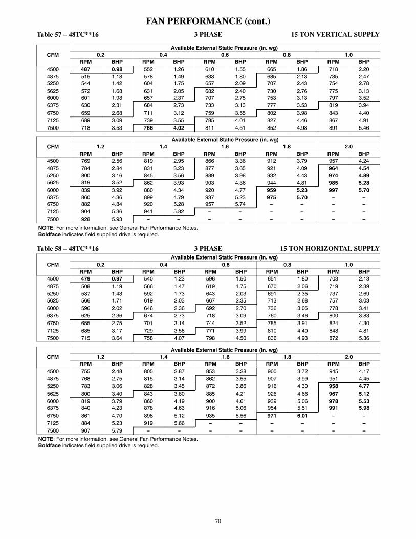
70
FAN PERFORMANCE (cont.)Table 57 – 48TC**16 3 PHASE 15 TON VERTICAL SUPPLY
CFMAvailable External Static Pressure (in. wg)
0.2 0.4 0.6 0.8 1.0RPM BHP RPM BHP RPM BHP RPM BHP RPM BHP
4500 487 0.98 552 1.26 610 1.55 665 1.86 718 2.204875 515 1.18 578 1.49 633 1.80 685 2.13 735 2.475250 544 1.42 604 1.75 657 2.09 707 2.43 754 2.785625 572 1.68 631 2.05 682 2.40 730 2.76 775 3.136000 601 1.98 657 2.37 707 2.75 753 3.13 797 3.526375 630 2.31 684 2.73 733 3.13 777 3.53 819 3.946750 659 2.68 711 3.12 759 3.55 802 3.98 843 4.407125 689 3.09 739 3.55 785 4.01 827 4.46 867 4.917500 718 3.53 766 4.02 811 4.51 852 4.98 891 5.46
CFMAvailable External Static Pressure (in. wg)
1.2 1.4 1.6 1.8 2.0RPM BHP RPM BHP RPM BHP RPM BHP RPM BHP
4500 769 2.56 819 2.95 866 3.36 912 3.79 957 4.244875 784 2.84 831 3.23 877 3.65 921 4.09 964 4.545250 800 3.16 845 3.56 889 3.98 932 4.43 974 4.895625 819 3.52 862 3.93 903 4.36 944 4.81 985 5.286000 839 3.92 880 4.34 920 4.77 959 5.23 997 5.706375 860 4.36 899 4.79 937 5.23 975 5.70 --- ---6750 882 4.84 920 5.28 957 5.74 --- --- --- ---7125 904 5.36 941 5.82 --- --- --- --- --- ---7500 928 5.93 --- --- --- --- --- --- --- ---
NOTE: For more information, see General Fan Performance Notes.Boldface indicates field supplied drive is required.
Table 58 – 48TC**16 3 PHASE 15 TON HORIZONTAL SUPPLY
CFMAvailable External Static Pressure (in. wg)
0.2 0.4 0.6 0.8 1.0RPM BHP RPM BHP RPM BHP RPM BHP RPM BHP
4500 479 0.97 540 1.23 596 1.50 651 1.80 703 2.134875 508 1.19 566 1.47 619 1.75 670 2.06 719 2.395250 537 1.43 592 1.73 643 2.03 691 2.35 737 2.695625 566 1.71 619 2.03 667 2.35 713 2.68 757 3.036000 596 2.02 646 2.36 692 2.70 736 3.05 778 3.416375 625 2.36 674 2.73 718 3.09 760 3.46 800 3.836750 655 2.75 701 3.14 744 3.52 785 3.91 824 4.307125 685 3.17 729 3.58 771 3.99 810 4.40 848 4.817500 715 3.64 758 4.07 798 4.50 836 4.93 872 5.36
CFMAvailable External Static Pressure (in. wg)
1.2 1.4 1.6 1.8 2.0RPM BHP RPM BHP RPM BHP RPM BHP RPM BHP
4500 755 2.48 805 2.87 853 3.28 900 3.72 945 4.174875 768 2.75 815 3.14 862 3.55 907 3.99 951 4.455250 783 3.06 828 3.45 872 3.86 916 4.30 958 4.775625 800 3.40 843 3.80 885 4.21 926 4.66 967 5.126000 819 3.79 860 4.19 900 4.61 939 5.06 978 5.536375 840 4.23 878 4.63 916 5.06 954 5.51 991 5.986750 861 4.70 898 5.12 935 5.56 971 6.01 --- ---7125 884 5.23 919 5.66 --- --- --- --- --- ---7500 907 5.79 --- --- --- --- --- --- --- ---
NOTE: For more information, see General Fan Performance Notes.Boldface indicates field supplied drive is required.

71
FAN PERFORMANCE (cont.)
Table 59 – PULLEY ADJUSTMENT
UNITMOTOR/DRIVECOMBO
MOTOR PULLEY TURNS OPEN (RPM)0.0 0.5 1.0 1.5 2.0 2.5 3.0 3.5 4.0 4.5 5.0
04
1phase Standard Static 854 825 795 766 736 707 678 648 619 589 560
Medium Static 1175 1135 1094 1054 1013 973 932 892 851 811 770
High Static --- --- --- --- --- --- --- --- --- --- ---
3phase Standard Static 854 825 795 766 736 707 678 648 619 589 560
Medium Static 1175 1135 1094 1054 1013 973 932 892 851 811 770
High Static 1466 1423 1380 1337 1294 1251 1207 1164 1121 1078 1035
05
1phase Standard Static 854 825 795 766 736 707 678 648 619 589 560
Medium Static 1175 1135 1094 1054 1013 973 932 892 851 811 770
High Static --- --- --- --- --- --- --- --- --- --- ---
3phase Standard Static 854 825 795 766 736 707 678 648 619 589 560
Medium Static 1175 1135 1094 1054 1013 973 932 892 851 811 770
High Static 1466 1423 1380 1337 1294 1251 1207 1164 1121 1078 1035
06
1phase Standard Static 1175 1135 1094 1054 1013 973 932 892 851 811 770
Medium Static 1466 1423 1380 1337 1294 1251 1207 1164 1121 1078 1035
High Static --- --- --- --- --- --- --- --- --- --- ---
3phase Standard Static 1175 1135 1094 1054 1013 973 932 892 851 811 770
Medium Static 1466 1423 1380 1337 1294 1251 1207 1164 1121 1078 1035
High Static 1687 1649 1610 1572 1533 1495 1457 1418 1380 1341 1303
07
3phase Standard Static 1457 1419 1380 1342 1303 1265 1227 1188 1150 1111 1073
Medium Static 1518 1484 1449 1415 1380 1346 1311 1277 1242 1208 1173
High Static 1788 1757 1725 1694 1662 1631 1600 1568 1537 1505 1474
08
3phase Standard Static 747 721 695 670 644 618 592 566 541 515 489
Medium Static 949 927 906 884 863 841 819 798 776 755 733
High Static 1102 1083 1063 1044 1025 1006 986 967 948 928 909
09
3phase Standard Static 733 712 690 669 647 626 604 583 561 540 518
Medium Static 936 911 887 862 838 813 788 764 739 715 690
High Static 1084 1059 1035 1010 986 961 936 912 887 863 838
12
3phase Standard Static 838 813 789 764 739 715 690 665 640 616 591
Medium Static 1084 1059 1035 1010 986 961 936 912 887 863 838
High Static 1240 1218 1196 1175 1153 1131 1109 1087 1066 1044 1022
14
3phase Standard Static 843 824 805 786 767 748 728 709 690 671 652
Medium Static 1084 1059 1035 1010 986 961 936 912 887 863 838
High Static 1240 1218 1196 1175 1153 1131 1109 1087 1066 1044 1022
16
3phase Standard Static 676 659 642 625 608 592 575 558 541 524 507
Medium Static 851 829 806 784 761 739 717 694 672 649 627
High Static 955 937 919 901 883 866 848 830 812 794 776
NOTE: Do not adjust pulley further than 5 turns open.--- Factory settings

72
ELECTRICAL DATA FOR UNITSPRODUCED ON OR AFTER JULY 30, 2012
NOTE: Check the serial number of unit to verify production date.
To confirm the date of manufacture, locate the unit nameplate and check the first four digits of the Serial Number. If thenumber listed in the first 4 digits of the Serial Number is 3112 or higher, the unit was produced on or after July 30, 2012.
Week of manufacture(fiscal calendar)
Manufacturing location
Sequence number
Year of manufacture ("12" = 2012)
Position:Example:
1 2 3 4 5 6 7 8 9 103 1 1 2 U 1 2 3 4 5
C12562A

73
ELECTRICAL INFORMATION(UNITS PRODUCED ON OR AFTER JULY 30, 2012)
Table 60 – 48TC**04 SINGLE STAGE COOLING WITH SINGLE SPEED INDOOR FAN MOTOR 3 TONS
V---Ph---HzVOLTAGERANGE
COMP (ea) OFM (ea) IFM
RLA LRA WATTS FLA TYPE EFF atFull Load
FLAMIN MAX
208---1---60 187 253 16.6 79325 1.5 STD 67% 4.9325 1.5 MED 67% 4.9
230---1---60 187 253 16.6 79325 1.5 STD 67% 4.9325 1.5 MED 67% 4.9
208---3---60 187 253 10.4 73325 1.5 STD 75% 5.2325 1.5 MED 75% 5.2325 1.5 HIGH 87% 6.9
230---3---60 187 253 10.4 73325 1.5 STD 75% 5.2325 1.5 MED 75% 5.2325 1.5 HIGH 87% 6.7
460---3---60 414 506 5.8 38325 0.8 STD 75% 2.6325 0.8 MED 75% 2.6325 0.8 HIGH 87% 3.4
575---3---60 518 633 3.8 37325 0.6 STD 73% 2.4325 0.6 MED 73% 2.4325 0.6 HIGH 78% 2.0
Table 61 – 48TC**05 SINGLE STAGE COOLING WITH SINGLE SPEED INDOOR FAN MOTOR 4 TONS
V---Ph---HzVOLTAGERANGE
COMP (ea) OFM (ea) IFM
RLA LRA WATTS FLA TYPE EFF atFull Load
FLAMIN MAX
208---1---60 187 253 21.8 117325 1.5 STD 67% 4.9325 1.5 MED 67% 4.9
230---1---60 187 253 21.8 117325 1.5 STD 67% 4.9325 1.5 MED 67% 4.9
208---3---60 187 253 13.7 83325 1.5 STD 75% 5.2325 1.5 MED 75% 5.2325 1.5 HIGH 87% 6.9
230---3---60 187 253 13.7 83325 1.5 STD 75% 5.2325 1.5 MED 75% 5.2325 1.5 HIGH 87% 6.7
460---3---60 414 506 6.2 41325 0.8 STD 75% 2.6325 0.8 MED 75% 2.6325 0.8 HIGH 87% 3.4
575---3---60 518 633 4.8 33325 0.6 STD 73% 2.4325 0.6 MED 73% 2.4325 0.6 HIGH 78% 2.0
Table 62 – 48TC**06 SINGLE STAGE COOLING WITH SINGLE SPEED INDOOR FAN MOTOR 5 TONS
V---Ph---HzVOLTAGERANGE
COMP (ea) OFM (ea) IFM
RLA LRA WATTS FLA TYPE EFF atFull Load
FLAMIN MAX
208---1---60 187 253 26.2 134325 1.5 STD 67% 4.9325 1.5 MED 76% 7.0
230---1---60 187 253 26.2 134325 1.5 STD 67% 4.9325 1.5 MED 76% 7.0
208---3---60 187 253 15.6 110325 1.5 STD 75% 5.2325 1.5 MED 87% 6.9325 1.5 HIGH 89% 8.4
230---3---60 187 253 15.6 110325 1.5 STD 75% 5.2325 1.5 MED 87% 6.7325 1.5 HIGH 89% 8.3
460---3---60 414 506 7.7 52325 0.8 STD 75% 2.6325 0.8 MED 87% 3.4325 0.8 HIGH 89% 4.2
575---3---60 518 633 5.8 39325 0.6 STD 73% 2.4325 0.6 MED 78% 2.0325 0.6 HIGH 77% 2.8
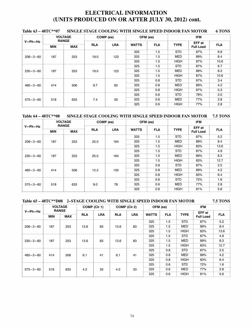
74
ELECTRICAL INFORMATION(UNITS PRODUCED ON OR AFTER JULY 30, 2012) cont.
Table 63 – 48TC**07 SINGLE STAGE COOLING WITH SINGLE SPEED INDOOR FAN MOTOR 6 TONS
V---Ph---HzVOLTAGERANGE
COMP (ea) OFM (ea) IFM
RLA LRA WATTS FLA TYPE EFF atFull Load FLAMIN MAX
208---3---60 187 253 19.0 123325 1.5 STD 87% 6.9325 1.5 MED 89% 8.4325 1.5 HIGH 87% 10.6
230---3---60 187 253 19.0 123325 1.5 STD 87% 6.7325 1.5 MED 89% 8.3325 1.5 HIGH 87% 10.6
460---3---60 414 506 9.7 62325 0.8 STD 87% 3.4325 0.8 MED 89% 4.2325 0.8 HIGH 87% 5.3
575---3---60 518 633 7.4 50325 0.6 STD 78% 2.0325 0.6 MED 77% 2.8325 0.6 HIGH 77% 2.8
Table 64 – 48TC**08 SINGLE STAGE COOLING WITH SINGLE SPEED INDOOR FAN MOTOR 7.5 TONS
V---Ph---HzVOLTAGERANGE
COMP (ea) OFM (ea) IFM
RLA LRA WATTS FLA TYPE EFF atFull Load FLAMIN MAX
208---3---60 187 253 25.0 164325 1.5 STD 87% 5.2325 1.5 MED 89% 8.4325 1.5 HIGH 83% 13.6
230---3---60 187 253 25.0 164325 1.5 STD 87% 4.9325 1.5 MED 89% 8.3325 1.5 HIGH 83% 12.7
460---3---60 414 506 12.2 100325 0.8 STD 87% 2.5325 0.8 MED 89% 4.2325 0.8 HIGH 83% 6.4
575---3---60 518 633 9.0 78325 0.6 STD 72% 1.6325 0.6 MED 77% 2.8325 0.6 HIGH 81% 5.6
Table 65 – 48TC**D08 2--STAGE COOLING WITH SINGLE SPEED INDOOR FAN MOTOR 7.5 TONS
V---Ph---HzVOLTAGERANGE
COMP (Cir 1) COMP (Cir 2) OFM (ea) IFM
RLA LRA RLA LRA WATTS FLA TYPE EFF atFull Load FLAMIN MAX
208---3---60 187 253 13.6 83 13.6 83325 1.5 STD 87% 5.2325 1.5 MED 89% 8.4325 1.5 HIGH 83% 13.6
230---3---60 187 253 13.6 83 13.6 83325 1.5 STD 87% 4.9325 1.5 MED 89% 8.3325 1.5 HIGH 83% 12.7
460---3---60 414 506 6.1 41 6.1 41325 0.8 STD 87% 2.5325 0.8 MED 89% 4.2325 0.8 HIGH 83% 6.4
575---3---60 518 633 4.2 33 4.2 33325 0.6 STD 72% 1.6325 0.6 MED 77% 2.8325 0.6 HIGH 81% 5.6

75
ELECTRICAL INFORMATION(UNITS PRODUCED ON OR AFTER JULY 30, 2012) cont.
Table 66 – 48TC*D08 2--STAGE COOLING WITH 2 SPEED INDOOR FAN MOTOR 7.5 TONS
V---Ph---HzVOLTAGERANGE
COMP 1 COMP 2 OFM (ea) IFM
RLA LRA RLA LRA WATTS FLA TYPE EFF atFull Load FLAMIN MAX
208---3---60 187 253 13.6 83 13.6 83325 1.5 STD 0.84 5.8325 1.5 MED 0.85 8.6325 1.5 HIGH 0.84 13.6
230---3---60 187 253 13.6 83 13.6 83325 1.5 STD 0.84 5.6325 1.5 MED 0.85 7.8325 1.5 HIGH 0.84 12.7
460---3---60 414 506 6.1 41 6.1 41325 0.8 STD 0.79 2.9325 0.8 MED 0.85 3.8325 0.8 HIGH 0.84 6.4
575---3---60 518 633 4.2 33 4.2 33325 0.6 STD 0.81 2.8325 0.6 MED 0.84 4.5325 0.6 HIGH 0.83 6.2
Table 67 – 48TC**09 SINGLE STAGE COOLING WITH SINGLE SPEED INDOOR FAN MOTOR 8.5 TONS
V---Ph---HzVOLTAGERANGE
COMP (ea) OFM (ea) IFM
RLA LRA WATTS FLA TYPE EFF atFull Load FLAMIN MAX
208---3---60 187 253 29.5 195325 1.5 STD 87% 5.2325 1.5 MED 87% 6.9325 1.5 HIGH 87% 10.6
230---3---60 187 253 29.5 195325 1.5 STD 87% 4.9325 1.5 MED 87% 6.7325 1.5 HIGH 87% 10.6
460---3---60 414 506 14.7 95325 0.8 STD 87% 2.5325 0.8 MED 87% 3.4325 0.8 HIGH 87% 5.3
575---3---60 518 633 12.2 80325 0.6 STD 72% 1.6325 0.6 MED 78% 2.0325 0.6 HIGH 77% 2.8
Table 68 – 48TC**09 2--STAGE COOLING WITH SINGLE SPEED INDOOR FAN MOTOR 8.5 TONS
V---Ph---HzVOLTAGERANGE
COMP (Cir 1) COMP (Cir 2) OFM (ea) IFM
RLA LRA RLA LRA WATTS FLA TYPE EFF atFull Load FLAMIN MAX
208---3---60 187 253 14.5 98 13.7 83325 1.5 STD 87% 5.2325 1.5 MED 87% 6.9325 1.5 HIGH 87% 10.6
230---3---60 187 253 14.5 98 13.7 83325 1.5 STD 87% 4.9325 1.5 MED 87% 6.7325 1.5 HIGH 87% 10.6
460---3---60 414 506 6.3 55 6.2 41325 0.8 STD 87% 2.5325 0.8 MED 87% 3.4325 0.8 HIGH 87% 5.3
575---3---60 518 633 6.0 41 4.8 33325 0.6 STD 72% 1.6325 0.6 MED 78% 2.0325 0.6 HIGH 77% 2.8

76
ELECTRICAL INFORMATION(UNITS PRODUCED ON OR AFTER JULY 30, 2012) cont.
Table 69 – 48TC*D09 2--STAGE COOLING WITH 2 SPEED INDOOR FAN MOTOR 8.5 TONS
V---Ph---HzVOLTAGERANGE
COMP 1 COMP 2 OFM (ea) IFM
RLA LRA RLA LRA WATTS FLA TYPE EFF atFull Load FLAMIN MAX
208---3---60 187 253 14.5 98 13.7 83325 1.5 STD 0.84 5.8325 1.5 MED 0.77 7.1325 1.5 HIGH 0.82 10.8
230---3---60 187 253 14.5 98 13.7 83325 1.5 STD 0.84 5.6325 1.5 MED 0.77 6.8325 1.5 HIGH 0.82 9.8
460---3---60 414 506 6.3 55 6.2 41325 0.8 STD 0.79 2.9325 0.8 MED 0.77 3.8325 0.8 HIGH 0.82 4.9
575---3---60 518 633 6.0 41 4.8 33325 0.6 STD 0.81 2.8325 0.6 MED 0.80 3.5325 0.6 HIGH 0.84 4.5
Table 70 – 48TC**12 SINGLE STAGE COOLING WITH SINGLE SPEED INDOOR FAN MOTOR 10 TONS
V---Ph---HzVOLTAGERANGE
COMP (ea) OFM (ea) IFM
RLA LRA WATTS FLA TYPE EFF atFull Load FLAMIN MAX
208---3---60 187 253 30.1 225325 1.5 STD 87% 6.9325 1.5 MED 87% 10.6325 1.5 HIGH 83% 13.6
230---3---60 187 253 30.1 225325 1.5 STD 87% 6.7325 1.5 MED 87% 10.6325 1.5 HIGH 83% 12.7
460---3---60 414 506 16.7 114325 0.8 STD 87% 3.4325 0.8 MED 87% 5.3325 0.8 HIGH 83% 6.4
575---3---60 518 633 12.2 80325 0.6 STD 78% 2.0325 0.6 MED 77% 2.8325 0.6 HIGH 81% 5.6
Table 71 – 48TC**12 2--STAGE COOLING WITH SINGLE SPEED INDOOR FAN MOTOR 10 TONS
V---Ph---HzVOLTAGERANGE
COMP (Cir 1) COMP (Cir 2) OFM (ea) IFM
RLA LRA RLA LRA WATTS FLA TYPE EFF atFull Load FLAMIN MAX
208---3---60 187 253 15.6 110 15.9 110325 1.5 STD 87% 6.9325 1.5 MED 87% 10.6325 1.5 HIGH 83% 13.6
230---3---60 187 253 15.6 110 15.9 110325 1.5 STD 87% 6.7325 1.5 MED 87% 10.6325 1.5 HIGH 83% 12.7
460---3---60 414 506 7.7 52 7.7 52325 0.8 STD 87% 3.4325 0.8 MED 87% 5.3325 0.8 HIGH 83% 6.4
575---3---60 518 633 5.8 39 5.7 39325 0.6 STD 78% 2.0325 0.6 MED 77% 2.8325 0.6 HIGH 81% 5.6

77
ELECTRICAL INFORMATION(UNITS PRODUCED ON OR AFTER JULY 30, 2012) cont.
Table 72 – 48TC*D12 2--STAGE COOLING WITH 2 SPEED INDOOR FAN MOTOR 10 TONS
V---Ph---HzVOLTAGERANGE
COMP 1 COMP 2 OFM (ea) IFM
RLA LRA RLA LRA WATTS FLA TYPE EFF atFull Load FLAMIN MAX
208---3---60 187 253 15.6 110 15.9 110325 1.5 STD 0.77 7.1325 1.5 MED 0.82 10.8325 1.5 HIGH 0.84 13.6
230---3---60 187 253 15.6 110 15.9 110325 1.5 STD 0.77 6.8325 1.5 MED 0.82 9.8325 1.5 HIGH 0.84 12.7
460---3---60 414 506 7.7 52 7.7 52325 0.8 STD 0.77 3.8325 0.8 MED 0.82 4.9325 0.8 HIGH 0.84 6.4
575---3---60 518 633 5.8 39 5.7 39325 0.6 STD 0.80 3.5325 0.6 MED 0.84 4.5325 0.6 HIGH 0.83 6.2
Table 73 – 48TC**14 2--STAGE COOLING WITH SINGLE SPEED INDOOR FAN MOTOR 12.5 TONS
V---Ph---HzVOLTAGERANGE
COMP (Cir 1) COMP (Cir 2) OFM (ea) IFM
RLA LRA RLA LRA WATTS FLA TYPE EFF atFull Load FLAMIN MAX
208---3---60 187 253 19.0 123 22.4 1491070 6.2 STD 89% 8.41070 6.2 MED 87% 10.61070 6.2 HIGH 83% 13.6
230---3---60 187 253 19.0 123 22.4 1491070 6.2 STD 89% 8.31070 6.2 MED 87% 10.61070 6.2 HIGH 83% 12.7
460---3---60 414 506 9.7 62 10.6 751070 3.1 STD 89% 4.21070 3.1 MED 87% 5.31070 3.1 HIGH 83% 6.4
575---3---60 518 633 7.4 50 7.7 541070 2.5 STD 77% 2.81070 2.5 MED 77% 2.81070 2.5 HIGH 81% 5.6
Table 74 – 48TC*D14 2--STAGE COOLING WITH 2 SPEED INDOOR FAN MOTOR 12.5 TONS
V---Ph---HzVOLTAGERANGE
COMP 1 COMP 2 OFM (ea) IFM
RLA LRA RLA LRA WATTS FLA TYPE EFF atFull Load FLAMIN MAX
208---3---60 187 253 19.0 123 22.4 1491070 6.2 STD 0.85 8.61070 6.2 MED 0.82 10.81070 6.2 HIGH 0.84 13.6
230---3---60 187 253 19.0 123 22.4 1491070 6.2 STD 0.85 7.81070 6.2 MED 0.82 9.81070 6.2 HIGH 0.84 12.7
460---3---60 414 506 9.7 62 10.6 751070 3.1 STD 0.85 3.81070 3.1 MED 0.82 4.91070 3.1 HIGH 0.84 6.4
575---3---60 518 633 7.4 50 7.7 541070 2.5 STD 0.84 4.51070 2.5 MED 0.84 4.51070 2.5 HIGH 0.83 6.2

78
ELECTRICAL INFORMATION(UNITS PRODUCED ON OR AFTER JULY 30, 2012) cont.
Table 75 – 48TC*D16 2--STAGE COOLING WITH SINGLE SPEED INDOOR FAN MOTOR 15 TONS
V---Ph---HzVOLTAGERANGE
COMP (Cir 1) COMP (Cir 2) OFM (ea) IFM
RLA LRA RLA LRA WATTS FLA TYPE EFF atFull Load FLAMIN MAX
208---3---60 187 253 25.0 164 25.0 164280 1.5 STD 89% 8.4280 1.5 MED 87% 10.6280 1.5 HIGH 90% 20.4
230---3---60 187 253 25.0 164 25.0 164280 1.5 STD 89% 8.3280 1.5 MED 87% 10.6280 1.5 HIGH 90% 20.4
460---3---60 414 506 12.2 100 12.8 100280 0.8 STD 89% 4.2280 0.8 MED 87% 5.3280 0.8 HIGH 90% 10.2
575---3---60 518 633 9.8 78 9.6 78280 0.6 STD 77% 2.8280 0.6 MED 77% 2.8280 0.6 HIGH 94% 9.0
Table 76 – 48TC*D16 2--STAGE COOLING WITH 2 SPEED INDOOR FAN MOTOR 15 TONS
V---Ph---HzVOLTAGERANGE
COMP 1 COMP 2 OFM (ea) IFM
RLA LRA RLA LRA WATTS FLA TYPE EFF atFull Load FLAMIN MAX
208---3---60 187 253 25.0 164 25.0 164280 1.5 STD 0.85 8.6280 1.5 MED 0.82 10.8280 1.5 HIGH 0.90 20.4
230---3---60 187 253 25.0 164 25.0 164280 1.5 STD 0.85 7.8280 1.5 MED 0.82 9.8280 1.5 HIGH 0.90 20.4
460---3---60 414 506 12.2 100 12.8 100280 0.8 STD 0.85 3.8280 0.8 MED 0.82 4.9280 0.8 HIGH 0.90 10.2
575---3---60 518 633 9.8 78 9.6 78280 0.6 STD 0.84 4.5280 0.6 MED 0.84 4.5280 0.6 HIGH 0.94 9

79
ELECTRICALINFORMATION
(UNITSPRODUCEDONORAFTERJU
LY30,2012)cont.
Table77
–UNIT
WIRE/FUSE
ORHACRBREAKERSIZINGDATAWITHSINGLESPEEDINDOORFA
NMOTOR
UNIT
NOM.
V---Ph---Hz
IFMTYPE
NOC.O.orUNPWRC.O.
w/PWRDC.O.
NOP.E.
w/P.E.(pwrdfr/unit)
NOP.E.
w/P.E.(pwrdfr/unit)
MCA
MAX
FUSEor
HACR
BRKR
DISC.SIZE
MCA
MAX
FUSEor
HACR
BRKR
DISC.SIZE
MCA
MAX
FUSEor
HACR
BRKR
DISC.SIZE
MCA
MAX
FUSEor
HACR
BRKR
DISC.SIZE
FLA
LRA
FLA
LRA
FLA
LRA
FLA
LRA
48TC**04
208/230---1---60
STD
2840
2695
3045
2997
3245
32100
3450
34102
MED
2840
2695
3045
2997
3245
32100
3450
34102
208/230---3---60
STD
2030
2096
2230
2298
2530
25101
2730
27103
MED
2030
2096
2230
2298
2530
25101
2730
27103
HIGH
22/22
30/30
22/21
134
24/24
30/30
24/24
136
27/26
30/30
27/27
139
29/28
35/35
29/29
141
460---3---60
STD
1115
1149
1215
1250
1315
1351
1420
1452
MED
1115
1149
1215
1250
1315
1351
1420
1452
HIGH
1215
1268
1315
1369
1420
1470
1520
1571
575---3---60
STD
815
846
1015
1048
1015
1048
1215
1250
MED
815
846
1015
1048
1015
1048
1215
1250
HIGH
815
750
1015
1052
1015
952
1115
1254
48TC**05
208/230---1---60
STD
3450
32133
3650
35135
3960
38138
4160
40140
MED
3450
32133
3650
35135
3960
38138
4160
40140
208/230---3---60
STD
2430
23106
2630
26108
2940
29111
3140
31113
MED
2430
23106
2630
26108
2940
29111
3140
31113
HIGH
26/26
30/30
25/25
144
28/28
40/40
28/27
146
31/31
40/40
31/31
149
33/32
45/45
33/33
151
460---3---60
STD
1215
1152
1315
1253
1415
1454
1520
1555
MED
1215
1152
1315
1253
1415
1454
1520
1555
HIGH
1215
1271
1315
1372
1520
1473
1620
1674
575---3---60
STD
915
942
1115
1144
1115
1144
1315
1346
MED
915
942
1115
1144
1115
1144
1315
1346
HIGH
915
946
1115
1148
1115
1048
1315
1350

80
ELECTRICALINFORMATION
(UNITSPRODUCEDONORAFTERJU
LY30,2012)cont.
Table77
--UNIT
WIRE/FUSE
ORHACRBREAKERSIZINGDATAWITHSINGLESPEEDINDOORFA
NMOTOR(cont.)
UNIT
NOM.
V---Ph---Hz
IFMTYPE
NOC.O.orUNPWRC.O.
w/PWRDC.O.
NOP.E.
w/P.E.(pwrdfr/unit)
NOP.E.
w/P.E.(pwrdfr/unit)
MCA
MAX
FUSEor
HACR
BRKR
DISC.SIZE
MCA
MAX
FUSEor
HACR
BRKR
DISC.SIZE
MCA
MAX
FUSEor
HACR
BRKR
DISC.SIZE
MCA
MAX
FUSEor
HACR
BRKR
DISC.SIZE
FLA
LRA
FLA
LRA
FLA
LRA
FLA
LRA
48TC**06
208/230---1---60
STD
4060
37150
4260
40152
4460
43155
4660
45157
MED
4260
40175
4460
42177
4760
45180
4860
48182
208/230---3---60
STD
2740
26133
2940
28135
3145
31138
3345
33140
MED
28/28
40/40
28/27
171
30/30
45/45
30/30
173
33/33
45/45
33/33
176
35/35
50/50
35/35
178
HIGH
30/30
45/40
29/29
186
32/32
45/45
32/31
188
35/35
45/45
35/35
191
37/36
50/50
37/37
193
460---3---60
STD
1320
1363
1420
1464
1620
1565
1720
1666
MED
1420
1482
1520
1583
1620
1684
1720
1785
HIGH
1520
1590
1620
1691
1720
1792
1825
1893
575---3---60
STD
1115
1048
1315
1250
1215
1250
1420
1452
MED
1015
1052
1215
1254
1215
1254
1415
1456
HIGH
1115
1163
1315
1365
1315
1365
1520
1567
48TC**07
208/230---3---60
STD
33/32
50/50
32/31
184
35/34
50/50
34/33
186
37/37
50/50
37/37
189
39/39
50/50
39/39
191
MED
34/34
50/50
33/33
199
36/36
50/50
35/35
201
39/39
50/50
39/39
204
41/41
50/50
41/41
206
HIGH
3650
36213
3850
38215
4150
41218
4360
43220
460---3---60
STD
1725
1692
1825
1793
1925
1994
2025
2095
MED
1825
17100
1925
18101
2025
19102
2130
21103
HIGH
1925
18107
2025
19108
2130
21109
2230
22110
575---3---60
STD
1215
1263
1420
1465
1420
1365
1620
1667
MED
1320
1274
1520
1576
1520
1476
1720
1778
HIGH
1320
1274
1520
1576
1520
1476
1720
1778
48TC*A08
208/230---3---60
STD
40/40
60/60
38/38
208
44/43
60/60
43/42
212
45/44
60/60
44/43
213
49/48
60/60
48/48
217
MED
43/43
60/60
42/42
244
47/47
60/60
46/46
248
48/48
60/60
47/47
249
52/52
60/60
52/52
253
HIGH
48/47
60/60
48/47
260
52/51
60/60
52/51
264
53/52
60/60
53/52
265
57/56
80/80
58/57
269
460---3---60
STD
2030
19122
2230
21124
2230
21124
2430
23126
MED
2230
21140
2330
23142
2430
23142
2630
25144
HIGH
2430
23148
2630
25150
2630
26150
2835
28152
575---3---60
STD
1520
1489
1825
1893
1620
1691
2025
2095
MED
1620
15104
2025
19108
1725
17106
2125
21110
HIGH
1925
18118
2230
23122
2025
20120
2430
24124

81
ELECTRICALINFORMATION
(UNITSPRODUCEDONORAFTERJU
LY30,2012)cont.
Table77
--UNIT
WIRE/FUSE
ORHACRBREAKERSIZINGDATAWITHSINGLESPEEDINDOORFA
NMOTOR(cont.)
UNIT
NOM.
V---Ph---Hz
IFMTYPE
NOC.O.orUNPWRC.O.
w/PWRDC.O.
NOP.E.
w/P.E.(pwrdfr/unit)
NOP.E.
w/P.E.(pwrdfr/unit)
MCA
MAX
FUSEor
HACR
BRKR
DISC.SIZE
MCA
MAX
FUSEor
HACR
BRKR
DISC.SIZE
MCA
MAX
FUSEor
HACR
BRKR
DISC.SIZE
MCA
MAX
FUSEor
HACR
BRKR
DISC.SIZE
FLA
LRA
FLA
LRA
FLA
LRA
FLA
LRA
48TC*D08
208/230---3---60
STD
39/39
50/50
41/40
210
43/43
50/50
45/45
214
44/44
50/50
46/46
215
48/48
60/60
51/50
219
MED
42/42
50/50
44/44
246
46/46
50/50
49/49
250
47/47
60/60
50/50
251
51/51
60/60
54/54
255
HIGH
48/47
60/50
50/49
262
51/51
60/60
55/54
266
52/52
60/60
56/55
267
56/55
60/60
60/59
271
460---3---60
STD
1820
19104
2025
21106
2025
21106
2225
23108
MED
2025
21122
2225
23124
2225
23124
2430
25126
HIGH
2225
23130
2430
25132
2430
26132
2630
28134
575---3---60
STD
1315
1377
1720
1781
1415
1579
1820
1983
MED
1415
1492
1820
1996
1620
1694
1925
2198
HIGH
1720
17106
2125
22110
1920
19108
2325
24112
48TC*A09
208/230---3---60
STD
46/45
60/60
43/43
239
49/49
60/60
48/47
243
50/50
60/60
49/49
244
54/54
80/80
53/53
248
MED
47/47
60/60
45/45
260
51/51
60/60
50/49
264
52/52
60/60
51/51
265
56/56
80/80
55/55
269
HIGH
5160
50289
5580
54293
5680
55294
6080
59298
460---3---60
STD
2330
22117
2530
24119
2530
24119
2740
26121
MED
2430
23127
2630
25129
2630
25129
2840
27131
HIGH
2630
25142
2840
27144
2840
27144
3040
29146
575---3---60
STD
1930
1791
2230
2295
2030
1993
2430
2497
MED
1930
1895
2330
2299
2130
2097
2430
24101
HIGH
2030
19106
2430
23110
2130
21108
2530
25112
48TC*D09
208/230---3---60
STD
40/40
50/50
42/42
225
44/44
50/50
46/46
229
45/45
50/50
47/47
230
49/49
60/60
52/51
234
MED
42/42
50/50
44/44
246
46/46
60/50
48/48
250
47/47
60/60
49/49
251
51/51
60/60
54/53
255
HIGH
4650
48275
5060
52279
5160
54280
5460
58284
460---3---60
STD
1920
19118
2025
21120
2125
22120
2325
24122
MED
2025
20128
2125
22130
2225
23130
2425
25132
HIGH
2125
22143
2325
24145
2425
25145
2530
27147
575---3---60
STD
1620
1685
1925
2089
1720
1887
2125
2291
MED
1620
1689
2025
2093
1820
1891
2125
2295
HIGH
1720
17100
2125
21104
1820
19102
2225
23106

82
ELECTRICALINFORMATION
(UNITSPRODUCEDONORAFTERJU
LY30,2012)cont.
Table77
--UNIT
WIRE/FUSE
ORHACRBREAKERSIZINGDATAWITHSINGLESPEEDINDOORFA
NMOTOR(cont.)
UNIT
NOM.
V---Ph---Hz
IFMTYPE
NOC.O.orUNPWRC.O.
w/PWRDC.O.
NOP.E.
w/P.E.(pwrdfr/unit)
NOP.E.
w/P.E.(pwrdfr/unit)
MCA
MAX
FUSEor
HACR
BRKR
DISC.SIZE
MCA
MAX
FUSEor
HACR
BRKR
DISC.SIZE
MCA
MAX
FUSEor
HACR
BRKR
DISC.SIZE
MCA
MAX
FUSEor
HACR
BRKR
DISC.SIZE
FLA
LRA
FLA
LRA
FLA
LRA
FLA
LRA
48TC*A12
208/230---3---60
STD
48/48
60/60
46/46
290
52/52
60/60
50/50
294
53/53
60/60
52/51
295
57/56
80/80
56/56
299
MED
5260
50319
5580
55323
5680
56324
6080
60328
HIGH
55/54
80/80
54/53
321
58/58
80/80
58/57
325
59/59
80/80
59/58
326
63/62
80/80
64/63
330
460---3---60
STD
2640
25146
2840
27148
2940
27148
3045
30150
MED
2840
27161
3045
29163
3045
30163
3245
32165
HIGH
2945
28162
3145
30164
3245
31164
3345
33166
575---3---60
STD
1930
1895
2330
2299
2130
2097
2430
24101
MED
2030
19106
2430
23110
2130
21108
2530
25112
HIGH
2330
22120
2630
26124
2430
24122
2835
28126
48TC*D12
208/230---3---60
STD
46/46
60/60
48/47
285
50/49
60/60
52/52
289
51/50
60/60
53/53
290
54/54
60/60
58/57
294
MED
5060
52314
5360
56318
5460
57319
5870
62323
HIGH
53/52
60/60
55/54
316
56/55
60/60
60/59
320
57/56
70/60
61/60
321
61/60
70/70
65/64
325
460---3---60
STD
2330
23136
2530
26138
2530
26138
2730
28140
MED
2530
26151
2630
28153
2730
28153
2935
30155
HIGH
2630
27152
2830
29154
2830
29154
3035
32156
575---3---60
STD
1720
1793
2025
2197
1820
1995
2225
2399
MED
1720
18104
2125
22108
1925
20106
2325
24110
HIGH
2025
21118
2430
25122
2225
23120
2630
27124
48TC*D14
208/230---3---60
STD
62/62
80/80
64/64
376
66/66
80/80
69/69
380
67/67
80/80
70/70
381
71/71
80/80
74/74
385
MED
6480
67390
6880
71394
6980
72395
7380
77399
HIGH
67/66
80/80
70/69
392
71/70
80/80
75/74
396
460---3---60
STD
3140
32189
3340
34191
3340
34191
3540
36193
MED
3240
33196
3440
35198
3440
36198
3645
38200
HIGH
3340
34197
3540
36199
3545
37199
3745
39201
575---3---60
STD
2330
23142
2730
28146
2430
25144
2830
30148
MED
2330
23142
2730
28146
2430
25144
2830
30148
HIGH
2630
27156
2935
31160
2730
29158
3135
33162
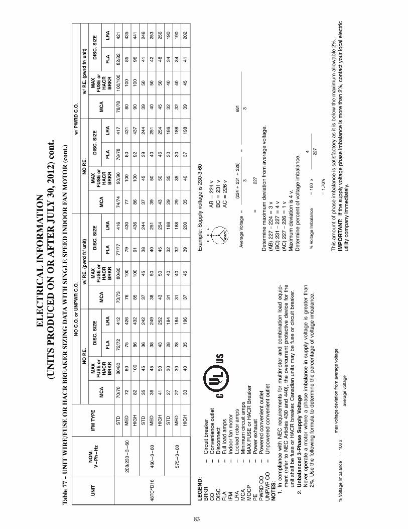
83
ELECTRICALINFORMATION
(UNITSPRODUCEDONORAFTERJU
LY30,2012)cont.
Table77
--UNIT
WIRE/FUSE
ORHACRBREAKERSIZINGDATAWITHSINGLESPEEDINDOORFA
NMOTOR(cont.)
UNIT
NOM.
V---Ph---Hz
IFMTYPE
NOC.O.orUNPWRC.O.
w/PWRDC.O.
NOP.E.
w/P.E.(pwrdfr/unit)
NOP.E.
w/P.E.(pwrdfr/unit)
MCA
MAX
FUSEor
HACR
BRKR
DISC.SIZE
MCA
MAX
FUSEor
HACR
BRKR
DISC.SIZE
MCA
MAX
FUSEor
HACR
BRKR
DISC.SIZE
MCA
MAX
FUSEor
HACR
BRKR
DISC.SIZE
FLA
LRA
FLA
LRA
FLA
LRA
FLA
LRA
48TC*D16
208/230---3---60
STD
70/70
80/80
72/72
412
73/73
80/80
77/77
416
74/74
90/90
78/78
417
78/78
100/100
82/82
421
MED
7280
75426
76100
79430
77100
80431
80100
85435
HIGH
82100
86432
85100
91436
86100
92437
90100
96441
460---3---60
STD
3545
36242
3745
38244
3745
39244
3950
41246
MED
3645
38249
3850
40251
3950
40251
4050
42253
HIGH
4150
43252
4350
45254
4350
46254
4550
48256
575---3---60
STD
2730
28184
3140
32188
2935
30186
3240
34190
MED
2730
28184
3140
32188
2935
30186
3240
34190
HIGH
3340
35196
3745
39200
3540
37198
3945
41202
LEGEND:
BRKR
---Circuitbreaker
CO
---Convenienceoutlet
DISC
---Disconnect
FLA
---Fullloadamps
IFM
---Indoorfanmotor
LRA
---Lockedrotoramps
MCA
---Minimumcircuitamps
MOCP
---MAXFUSEorHACRBreaker
PE
---Powerexhaust
PWRDCO
---Poweredconvenientoutlet
UNPWRCO
---Unpoweredconvenientoutlet
NOTES:
1.IncompliancewithNECrequirementsformultimotorandcombinationloadequip-
ment(refertoNECArticles430and440),theovercurrentprotectivedeviceforthe
unitshallbefuseorHACRbreaker.Canadianunitsmaybefuseorcircuitbreaker.
2.Unbalanced3-PhaseSupplyVoltage
Neveroperateamotorwhereaphaseimbalanceinsupplyvoltageisgreaterthan
2%.Usethefollowingformulatodeterminethepercentageofvoltageimbalance.
%VoltageImbalance=100x
maxvoltagedeviationfromaveragevoltage
averagevoltage
Example:Supplyvoltageis230-3-60
AB=224v
BC=231v
AC=226v
AverageVoltage=
(224+231+226)
=681
33
=227
Determinemaximumdeviationfromaveragevoltage.
(AB)227–224=3v
(BC)231–227=4v
(AC)227–226=1v
Maximumdeviationis4v.
Determinepercentofvoltageimbalance.
%VoltageImbalance
=100x
4 227
=1.76%
Thisamountofphaseimbalanceissatisfactoryasitisbelowthemaximumallowable2%.
IMPORTANT:Ifthesupplyvoltagephaseimbalanceismorethan2%,contactyourlocalelectric
utilitycompanyimmediately.

84
ELECTRICALINFORMATION
(UNITSPRODUCEDONORAFTERJU
LY30,2012)cont.
Table78
–UNIT
WIRE/FUSE
ORHACRBREAKERSIZINGDATAWITH2SPEEDINDOORFA
NMOTOR
UNIT
NOM.
V---Ph---Hz
IFMTYPE
NOC.O.orUNPWRC.O.
w/PWRDC.O.
NOP.E.
w/P.E.(pwrdfr/unit)
NOP.E.
w/P.E.(pwrdfr/unit)
MCA
MAX
FUSEor
HACR
BRKR
DISC.SIZE
MCA
MAX
FUSEor
HACR
BRKR
DISC.SIZE
MCA
MAX
FUSEor
HACR
BRKR
DISC.SIZE
MCA
MAX
FUSEor
HACR
BRKR
DISC.SIZE
FLA
LRA
FLA
LRA
FLA
LRA
FLA
LRA
48TC*D08
208/230---3---60
STD
40/40
50/50
41/41
197
44/43
50/50
46/46
201
45/44
50/50
47/47
202
48/48
60/60
51/51
206
MED
43/42
50/50
45/44
227
46/46
50/50
49/48
231
47/47
60/50
50/49
232
51/50
60/60
55/54
236
HIGH
48/47
60/50
50/49
262
51/51
60/60
55/54
266
52/52
60/60
56/55
267
56/55
60/60
60/59
271
460---3---60
STD
1920
1997
2025
2199
2125
2299
2325
24101
MED
2025
20113
2125
22115
2225
23115
2425
25117
HIGH
2225
23130
2430
25132
2430
26132
2630
28134
575---3---60
STD
1415
1479
1820
1983
1620
1681
1925
2185
MED
1620
1692
1925
2196
1720
1894
2125
2398
HIGH
1820
18106
2225
23110
2025
20108
2325
24112
48TC*D09
208/230---3---60
STD
41/41
50/50
43/42
212
45/45
50/50
47/47
216
46/46
50/50
48/48
217
50/49
60/60
52/52
221
MED
42/42
50/50
44/44
216
46/46
60/50
48/48
220
47/47
60/60
50/49
221
51/51
60/60
54/54
225
HIGH
46/45
60/50
48/47
266
50/49
60/60
53/52
270
51/50
60/60
54/53
271
55/54
60/60
58/57
275
460---3---60
STD
1925
20111
2125
22113
2125
22113
2325
24115
MED
2025
21114
2225
23116
2225
23116
2430
25118
HIGH
2125
22139
2325
24141
2325
24141
2530
26143
575---3---60
STD
1720
1787
2125
2191
1820
1989
2225
2393
MED
1720
1891
2125
2295
1925
2093
2325
2497
HIGH
1820
19100
2225
23104
2025
21102
2430
25106
48TC*D12
208/230---3---60
STD
46/46
60/60
48/47
255
50/50
60/60
52/52
259
51/51
60/60
53/53
260
55/54
60/60
58/57
264
MED
50/49
60/60
52/51
305
54/53
60/60
56/55
309
55/54
60/60
58/56
310
58/57
70/70
62/61
314
HIGH
53/52
60/60
55/54
316
56/55
60/60
60/59
320
57/56
70/60
61/60
321
61/60
70/70
65/64
325
460---3---60
STD
2330
24122
2530
26124
2530
26124
2730
29126
MED
2430
25147
2630
27149
2630
28149
2830
30151
HIGH
2630
27152
2830
29154
2830
29154
3035
32156
575---3---60
STD
1820
1995
2225
2399
2025
2197
2425
25101
MED
1925
20104
2325
24108
2125
22106
2530
26110
HIGH
2125
22118
2530
26122
2325
24120
2630
28124

85
ELECTRICALINFORMATION
(UNITSPRODUCEDONORAFTERJU
LY30,2012)cont.
Table78
--UNIT
WIRE/FUSE
ORHACRBREAKERSIZINGDATAWITH2SPEEDINDOORFA
NMOTOR(cont.)
UNIT
NOM.
V---Ph---Hz
IFMTYPE
NOC.O.orUNPWRC.O.
w/PWRDC.O.
NOP.E.
w/P.E.(pwrdfr/unit)
NOP.E.
w/P.E.(pwrdfr/unit)
MCA
MAX
FUSEor
HACR
BRKR
DISC.SIZE
MCA
MAX
FUSEor
HACR
BRKR
DISC.SIZE
MCA
MAX
FUSEor
HACR
BRKR
DISC.SIZE
MCA
MAX
FUSEor
HACR
BRKR
DISC.SIZE
FLA
LRA
FLA
LRA
FLA
LRA
FLA
LRA
48TC*D14
208/230---3---60
STD
62/61
80/80
65/64
357
66/65
80/80
69/68
361
67/66
80/80
70/69
362
71/70
80/80
75/74
366
MED
64/63
80/80
67/66
381
68/67
80/80
72/70
385
69/68
80/80
73/72
386
73/72
80/80
77/76
390
HIGH
67/66
80/80
70/69
392
71/70
80/80
75/74
396
Modelnotavailableduetohighamperagedraw.
460---3---60
STD
3040
31180
3240
33182
3340
34182
3440
36184
MED
3140
33192
3340
35194
3440
35194
3545
37196
HIGH
3340
34197
3540
36199
3545
37199
3745
39201
575---3---60
STD
2430
25142
2830
30146
2630
27144
3035
32148
MED
2430
25142
2830
30146
2630
27144
3035
32148
HIGH
2630
27156
3035
32160
2830
29158
3235
34162
48TC*D16
208/230---3---60
STD
70/69
80/80
73/72
393
74/73
80/80
77/76
397
75/74
90/80
78/77
398
78/78
100/100
82/82
402
MED
72/71
80/80
75/74
417
76/75
100/90
79/78
421
77/76
100/100
81/79
422
81/80
100/100
85/84
426
HIGH
82100
86432
85100
91436
86100
92437
90100
96441
460---3---60
STD
3545
36233
3745
38235
3745
38235
3950
40237
MED
3645
37245
3850
39247
3850
40247
4050
42249
HIGH
4150
43252
4350
45254
4350
46254
4550
48256
575---3---60
STD
2935
30184
3240
34188
3035
32186
3440
36190
MED
2935
30184
3240
34188
3035
32186
3440
36190
HIGH
3340
35196
3745
39200
3540
37198
3945
41202

86
ELECTRICALINFORMATION
(UNITSPRODUCEDONORAFTERJU
LY30,2012)cont.
Table79
–UNIT
WIRE/FUSE
ORHACRBREAKERSIZINGDATAFOR2STAGECOOLINGWITH2SPEEDINDOORFA
NMOTOR
UNIT
NOM.
V---Ph---Hz
IFMTYPE
NOC.O.orUNPWRC.O.
w/PWRDC.O.
NOP.E.
w/P.E.(pwrdfr/unit)
NOP.E.
w/P.E.(pwrdfr/unit)
MCA
MAX
FUSEor
HACR
BRKR
DISC.SIZE
MCA
MAX
FUSEor
HACR
BRKR
DISC.SIZE
MCA
MAX
FUSEor
HACR
BRKR
DISC.SIZE
MCA
MAX
FUSEor
HACR
BRKR
DISC.SIZE
FLA
LRA
FLA
LRA
FLA
LRA
FLA
LRA
48TC*D08
208/
230---3---60
STD
39.4/39.2
50/50
41/41
197
43.2/43.0
50/50
46/46
201
44.2/44.0
50/50
47/47
202
48.0/47.8
60/60
51/51
206
MED
42.2/41.4
50/50
45/44
227
46.0/45.2
50/50
49/48
231
47.0/46.2
60/50
50/49
232
50.8/50.0
60/60
55/54
236
HIGH
47.2/46.3
60/50
50/49
262
51.0/50.1
60/60
55/54
266
52.0/51.1
60/60
56/55
267
55.8/54.9
60/60
60/59
271
460---3---60
STD
18.2
2019
9720.0
2521
9920.4
2522
9922.2
2524
101
MED
19.1
2520
113
20.9
2522
115
21.3
2523
115
23.1
2525
117
HIGH
21.8
2523
130
23.6
3025
132
24.0
3026
132
25.8
3028
134
575---3---60
STD
13.5
1514
7917.3
2019
8315.2
2016
8119.0
2521
85
MED
15.2
2016
9219.0
2521
9616.9
2018
9420.7
2523
98
HIGH
17.4
2018
106
21.2
2523
110
19.1
2520
108
22.9
2524
112
48TC*D09
208/
230---3---60
STD
40.6/40.4
50/50
43/42
212
44.4/44.2
50/50
47/47
216
45.4/45.2
50/50
48/48
217
49.2/49.0
60/60
52/52
221
MED
41.9/41.6
50/50
44/44
216
45.7/45.4
60/50
48/48
220
46.7/46.4
60/60
50/49
221
50.5/50.2
60/60
54/54
225
HIGH
45.6/44.6
60/50
48/47
266
49.4/48.4
60/60
53/52
270
50.4/49.4
60/60
54/53
271
54.2/53.2
60/60
58/57
275
460---3---60
STD
18.6
2520
111
20.4
2522
113
20.8
2522
113
22.6
2524
115
MED
19.5
2521
114
21.3
2523
116
21.7
2523
116
23.5
3025
118
HIGH
20.6
2522
139
22.4
2524
141
22.8
2524
141
24.6
3026
143
575---3---60
STD
16.3
2017
8720.1
2521
9118.0
2019
8921.8
2523
93
MED
17.0
2018
9120.8
2522
9518.7
2520
9322.5
2524
97
HIGH
18.0
2019
100
21.8
2523
104
19.7
2521
102
23.5
3025
106
48TC*D12
208/
230---3---60
STD
45.6/45.3
60/60
48/47
255
49.4/49.1
60/60
52/52
259
50.4/50.1
60/60
53/53
260
54.2/53.9
60/60
58/57
264
MED
49.3/48.3
60/60
52/51
305
53.1/52.1
60/60
56/55
309
54.1/53.1
60/60
58/56
310
57.9/56.9
70/70
62/61
314
HIGH
52.1/51.2
60/60
55/54
316
55.9/55.0
60/60
60/59
320
56.9/56.0
70/60
61/60
321
60.7/59.8
70/70
65/64
325
460---3---60
STD
22.7
3024
122
24.5
3026
124
24.9
3026
124
26.7
3029
126
MED
23.8
3025
147
25.6
3027
149
26.0
3028
149
27.8
3030
151
HIGH
25.3
3027
152
27.1
3029
154
27.5
3029
154
29.3
3532
156
575---3---60
STD
17.7
2019
9521.5
2523
9919.4
2521
9723.2
2525
101
MED
18.7
2520
104
22.5
2524
108
20.4
2522
106
24.2
3026
110
HIGH
20.5
2522
118
24.3
3026
122
22.2
2524
120
26.0
3028
124

87
ELECTRICALINFORMATION
(UNITSPRODUCEDONORAFTERJU
LY30,2012)cont.
Table79
--UNIT
WIRE/FUSE
ORHACRBREAKERSIZINGDATAFOR2STAGECOOLINGWITH2SPEEDINDOORFA
NMOTOR(cont.)
UNIT
NOM.
V---Ph---Hz
IFMTYPE
NOC.O.orUNPWRC.O.
w/PWRDC.O.
NOP.E.
w/P.E.(pwrdfr/unit)
NOP.E.
w/P.E.(pwrdfr/unit)
MCA
MAX
FUSEor
HACR
BRKR
DISC.SIZE
MCA
MAX
FUSEor
HACR
BRKR
DISC.SIZE
MCA
MAX
FUSEor
HACR
BRKR
DISC.SIZE
MCA
MAX
FUSEor
HACR
BRKR
DISC.SIZE
FLA
LRA
FLA
LRA
FLA
LRA
FLA
LRA
48TC*D14
208/
230---3---60
STD
61.8/61.0
80/80
65/64
357
65.6/64.8
80/80
69/68
361
66.6/65.8
80/80
70/69
362
70.4/69.6
80/80
75/74
366
MED
64.0/63.0
80/80
67/66
381
67.8/66.8
80/80
72/70
385
68.8/67.8
80/80
73/72
386
72.6/71.6
80/80
77/76
390
HIGH
66.8/65.9
80/80
70/69
392
70.6/69.7
80/80
75/74
396
Modelnotavailableduetohighamperagedraw.
460---3---60
STD
29.9
4031
180
31.7
4033
182
32.1
4034
182
33.9
4036
184
MED
31.0
4033
192
32.8
4035
194
33.2
4035
194
35.0
4537
196
HIGH
32.5
4034
197
34.3
4036
199
34.7
4537
199
36.5
4539
201
575---3---60
STD
24.0
3025
142
27.8
3030
146
25.7
3027
144
29.5
3532
148
MED
24.0
3025
142
27.8
3030
146
25.7
3027
144
29.5
3532
148
HIGH
25.7
3027
156
29.5
3532
160
27.4
3029
158
31.2
3534
162
48TC*D16
208/
230---3---60
STD
69.4/68.6
80/80
73/72
393
73.2/72.4
80/80
77/76
397
74.2/73.4
90/80
78/77
398
78.0/77.2100/100
82/82
402
MED
71.6/70.6
80/80
75/74
417
75.4/74.4
100/90
79/78
421
76.4/75.4100/100
81/79
422
80.2/79.2100/100
85/84
426
HIGH
81.2
100
86432
85.0
100
91436
86.0
100
92437
89.8
100
96441
460---3---60
STD
34.4
4536
233
36.2
4538
235
36.6
4538
235
38.4
5040
237
MED
35.5
4537
245
37.3
5039
247
37.7
5040
247
39.5
5042
249
HIGH
40.8
5043
252
42.6
5045
254
43.0
5046
254
44.8
5048
256
575---3---60
STD
28.2
3530
184
32.0
4034
188
29.9
3532
186
33.7
4036
190
MED
28.2
3530
184
32.0
4034
188
29.9
3532
186
33.7
4036
190
HIGH
32.7
4035
196
36.5
4539
200
34.4
4037
198
38.2
4541
202

88
ELECTRICAL DATA FOR UNITSPRODUCED PRIOR TO JULY 30, 2012
NOTE: Check the serial number of unit to verify production date.
To confirm the date of manufacture, locate the unit nameplate and check the first four digits of the Serial Number. If thenumber listed in the first 4 digits of the Serial Number is 3111 or lower, the unit was produced prior to July 30, 2012.
Week of manufacture(fiscal calendar)
Manufacturing location
Sequence number
Year of manufacture ("12" = 2012)
Position:Example:
1 2 3 4 5 6 7 8 9 103 1 1 2 U 1 2 3 4 5
C12562A

89
ELECTRICAL INFORMATION(UNITS PRODUCED PRIOR TO JULY 30, 2012)
Table 80 – 48TC**04 SINGLE STAGE COOLING WITH SINGLE SPEED INDOOR FAN MOTOR 3 TONS
V---Ph---HzVOLTAGERANGE
COMP (ea) OFM (ea) IFM
RLA LRA WATTS FLA TYPE EFF atFull Load
FLAMIN MAX
208---1---60 187 253 16.6 79 325 1.5STD 70% 4.9MED 70% 4.9
230---1---60 187 253 16.6 79 325 1.5STD 70% 4.9MED 70% 4.9
208---3---60 187 253 10.4 73 325 1.5STD 70% 4.9MED 70% 4.9HIGH 80% 5.2
230---3---60 187 253 10.4 73 325 1.5STD 70% 4.9MED 70% 4.9HIGH 80% 5.2
460---3---60 414 506 5.8 38 325 0.8STD 70% 2.1MED 70% 2.1HIGH 80% 2.6
575---3---60 518 633 3.8 37 325 0.6STD 71% 1.9MED 71% 1.9HIGH 80% 2.0
Table 81 – 48TC**05 SINGLE STAGE COOLING WITH SINGLE SPEED INDOOR FAN MOTOR 4 TONS
V---Ph---HzVOLTAGERANGE
COMP (ea) OFM (ea) IFM
RLA LRA WATTS FLA TYPE EFF atFull Load
FLAMIN MAX
208---1---60 187 253 21.8 117 325 1.5STD 70% 4.9MED 78% 7.0
230---1---60 187 253 21.8 117 325 1.5STD 70% 4.9MED 78% 7.0
208---3---60 187 253 13.7 83 325 1.5STD 70% 4.9MED 70% 4.9HIGH 80% 5.2
230---3---60 187 253 13.7 83 325 1.5STD 70% 4.9MED 70% 4.9HIGH 80% 5.2
460---3---60 414 506 6.2 41 325 0.8STD 70% 2.1MED 70% 2.1HIGH 80% 2.6
575---3---60 518 633 4.8 37 325 0.6STD 71% 1.9MED 71% 2.1HIGH 80% 2.0
Table 82 – 48TC*06 SINGLE STAGE COOLING WITH SINGLE SPEED INDOOR FAN MOTOR 5 TONS
V---Ph---HzVOLTAGERANGE
COMP (ea) OFM (ea) IFM
RLA LRA WATTS FLA TYPE EFF atFull Load
FLAMIN MAX
208---1---60 187 253 26.2 134 325 1.5STD 70% 4.9MED 78% 7.0
230---1---60 187 253 26.2 134 325 1.5STD 70% 4.9MED 78% 7.0
208---3---60 187 253 15.6 110 325 1.5STD 70% 4.9MED 80% 5.2HIGH 81% 7.5
230---3---60 187 253 15.6 110 325 1.5STD 70% 4.9MED 80% 5.2HIGH 81% 7.5
460---3---60 414 506 7.7 52 325 0.8STD 70% 2.1MED 80% 2.6HIGH 81% 3.4
575---3---60 518 633 5.8 39 325 0.6STD 71% 1.9MED 81% 2.0HIGH 81% 2.8
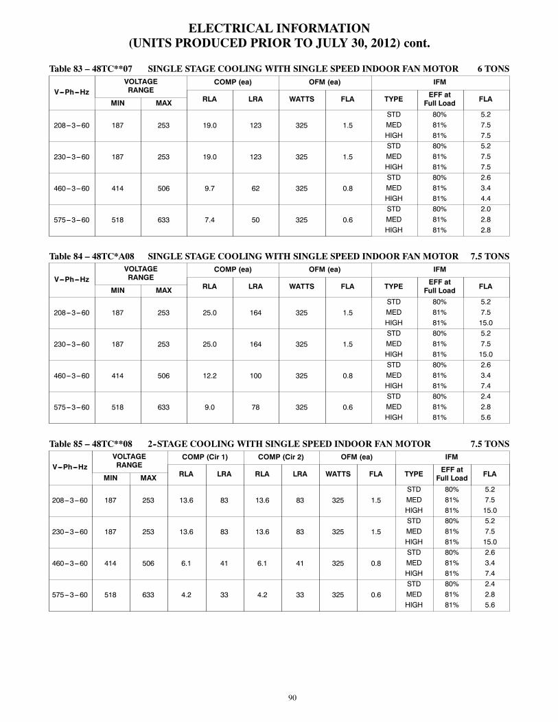
90
ELECTRICAL INFORMATION(UNITS PRODUCED PRIOR TO JULY 30, 2012) cont.
Table 83 – 48TC**07 SINGLE STAGE COOLING WITH SINGLE SPEED INDOOR FAN MOTOR 6 TONS
V---Ph---HzVOLTAGERANGE
COMP (ea) OFM (ea) IFM
RLA LRA WATTS FLA TYPE EFF atFull Load FLAMIN MAX
208---3---60 187 253 19.0 123 325 1.5STD 80% 5.2MED 81% 7.5HIGH 81% 7.5
230---3---60 187 253 19.0 123 325 1.5STD 80% 5.2MED 81% 7.5HIGH 81% 7.5
460---3---60 414 506 9.7 62 325 0.8STD 80% 2.6MED 81% 3.4HIGH 81% 4.4
575---3---60 518 633 7.4 50 325 0.6STD 80% 2.0MED 81% 2.8HIGH 81% 2.8
Table 84 – 48TC*A08 SINGLE STAGE COOLING WITH SINGLE SPEED INDOOR FAN MOTOR 7.5 TONS
V---Ph---HzVOLTAGERANGE
COMP (ea) OFM (ea) IFM
RLA LRA WATTS FLA TYPE EFF atFull Load FLAMIN MAX
208---3---60 187 253 25.0 164 325 1.5STD 80% 5.2MED 81% 7.5HIGH 81% 15.0
230---3---60 187 253 25.0 164 325 1.5STD 80% 5.2MED 81% 7.5HIGH 81% 15.0
460---3---60 414 506 12.2 100 325 0.8STD 80% 2.6MED 81% 3.4HIGH 81% 7.4
575---3---60 518 633 9.0 78 325 0.6STD 80% 2.4MED 81% 2.8HIGH 81% 5.6
Table 85 – 48TC**08 2--STAGE COOLING WITH SINGLE SPEED INDOOR FAN MOTOR 7.5 TONS
V---Ph---HzVOLTAGERANGE
COMP (Cir 1) COMP (Cir 2) OFM (ea) IFM
RLA LRA RLA LRA WATTS FLA TYPE EFF atFull Load FLAMIN MAX
208---3---60 187 253 13.6 83 13.6 83 325 1.5STD 80% 5.2MED 81% 7.5HIGH 81% 15.0
230---3---60 187 253 13.6 83 13.6 83 325 1.5STD 80% 5.2MED 81% 7.5HIGH 81% 15.0
460---3---60 414 506 6.1 41 6.1 41 325 0.8STD 80% 2.6MED 81% 3.4HIGH 81% 7.4
575---3---60 518 633 4.2 33 4.2 33 325 0.6STD 80% 2.4MED 81% 2.8HIGH 81% 5.6

91
ELECTRICAL INFORMATION(UNITS PRODUCED PRIOR TO JULY 30, 2012) cont.
Table 86 – 48TC**08 2--STAGE COOLING WITH 2 SPEED INDOOR FAN MOTOR 7.5 TONS
V---Ph---HzVOLTAGERANGE
COMP 1 COMP 2 OFM (ea) IFM
RLA LRA RLA LRA WATTS FLA TYPE EFF atFull Load FLAMIN MAX
208---3---60 187 253 13.6 83 13.6 83325 1.5 STD 84% 5.8325 1.5 MED 85% 8.6325 1.5 HIGH 84% 13.6
230---3---60 187 253 13.6 83 13.6 83325 1.5 STD 84% 5.6325 1.5 MED 85% 7.8325 1.5 HIGH 84% 12.7
460---3---60 414 506 6.1 41 6.1 41325 0.8 STD 79% 2.9325 0.8 MED 85% 3.8325 0.8 HIGH 84% 6.4
575---3---60 518 633 4.2 33 4.2 33325 0.6 STD 81% 2.8325 0.6 MED 84% 4.5325 0.6 HIGH 83% 6.2
Table 87 – 48TC**09 SINGLE STAGE COOLING WITH SINGLE SPEED INDOOR FAN MOTOR 8.5 TONS
V---Ph---HzVOLTAGERANGE
COMP (ea) OFM (ea) IFM
RLA LRA WATTS FLA TYPE EFF atFull Load FLAMIN MAX
208---3---60 187 253 29.5 195 325 1.5STD 80% 5.2MED 80% 5.2HIGH 80% 10.0
230---3---60 187 253 29.5 195 325 1.5STD 80% 5.2MED 80% 5.2HIGH 80% 10.0
460---3---60 414 506 14.7 95 325 0.8STD 80% 2.6MED 80% 2.6HIGH 80% 4.4
575---3---60 518 633 12.2 80 325 0.6STD 80% 2.4MED 80% 2.0HIGH 81% 2.8
Table 88 – 48TC**09 2--STAGE COOLING WITH SINGLE SPEED INDOOR FAN MOTOR 8.5 TONS
V---Ph---HzVOLTAGERANGE
COMP (Cir 1) COMP (Cir 2) OFM (ea) IFM
RLA LRA RLA LRA WATTS FLA TYPE EFF atFull Load FLAMIN MAX
208---3---60 187 253 14.5 98 13.7 83 325 1.5STD 80% 5.2MED 80% 5.2HIGH 80% 10.0
230---3---60 187 253 14.5 98 13.7 83 325 1.5STD 80% 5.2MED 80% 5.2HIGH 80% 10.0
460---3---60 414 506 6.3 55 6.2 41 325 0.8STD 80% 2.6MED 80% 2.6HIGH 80% 4.4
575---3---60 518 633 6.0 41 4.8 33 325 0.6STD 80% 2.4MED 80% 2.0HIGH 81% 2.8

92
ELECTRICAL INFORMATION(UNITS PRODUCED PRIOR TO JULY 30, 2012) cont.
Table 89 – 48TC**09 2--STAGE COOLING WITH 2 SPEED INDOOR FAN MOTOR 8.5 TONS
V---Ph---HzVOLTAGERANGE
COMP 1 COMP 2 OFM (ea) IFM
RLA LRA RLA LRA WATTS FLA TYPE EFF atFull Load FLAMIN MAX
208---3---60 187 253 14.5 98 13.7 83325 1.5 STD 84% 5.8325 1.5 MED 77% 7.1325 1.5 HIGH 82% 10.8
230---3---60 187 253 14.5 98 13.7 83325 1.5 STD 84% 5.6325 1.5 MED 77% 6.8325 1.5 HIGH 82% 9.8
460---3---60 414 506 6.3 55 6.2 41325 0.8 STD 79% 2.9325 0.8 MED 77% 3.8325 0.8 HIGH 82% 4.9
575---3---60 518 633 6.0 41 4.8 33325 0.6 STD 81% 2.8325 0.6 MED 80% 3.5325 0.6 HIGH 84% 4.5
Table 90 – 48TC**12 SINGLE STAGE COOLING WITH SINGLE SPEED INDOOR FAN MOTOR 10 TONS
V---Ph---HzVOLTAGERANGE
COMP (ea) OFM (ea) IFM
RLA LRA WATTS FLA TYPE EFF atFull Load FLAMIN MAX
208---3---60 187 253 30.1 225 325 1.5STD 80% 5.2MED 81% 10.0HIGH 81% 15.0
230---3---60 187 253 30.1 225 325 1.5STD 80% 5.2MED 81% 10.0HIGH 81% 15.0
460---3---60 414 506 16.7 114 325 0.8STD 80% 2.6MED 81% 4.4HIGH 81% 7.4
575---3---60 518 633 12.2 80 325 0.6STD 80% 2.0MED 81% 2.8HIGH 81% 5.6
Table 91 – 48TC**12 2--STAGE COOLING WITH SINGLE SPEED INDOOR FAN MOTOR 10 TONS
V---Ph---HzVOLTAGERANGE
COMP (Cir 1) COMP (Cir 2) OFM (ea) IFM
RLA LRA RLA LRA WATTS FLA TYPE EFF atFull Load FLAMIN MAX
208---3---60 187 253 15.6 110 15.9 110 325 1.5STD 80% 5.2MED 81% 10.0HIGH 81% 15.0
230---3---60 187 253 15.6 110 15.9 110 325 1.5STD 80% 5.2MED 81% 10.0HIGH 81% 15.0
460---3---60 414 506 7.7 52 7.7 52 325 0.8STD 80% 2.6MED 81% 4.4HIGH 81% 7.4
575---3---60 518 633 5.8 39 5.7 39 325 0.6STD 80% 2.0MED 81% 2.8HIGH 81% 5.6

93
ELECTRICAL INFORMATION(UNITS PRODUCED PRIOR TO JULY 30, 2012) cont.
Table 92 – 48TC**12 2--STAGE COOLING WITH 2 SPEED INDOOR FAN MOTOR 10 TONS
V---Ph---HzVOLTAGERANGE
COMP 1 COMP 2 OFM (ea) IFM
RLA LRA RLA LRA WATTS FLA TYPE EFF atFull Load FLAMIN MAX
208---3---60 187 253 15.6 110 15.9 110325 1.5 STD 77% 7.1325 1.5 MED 82% 10.8325 1.5 HIGH 84% 13.6
230---3---60 187 253 15.6 110 15.9 110325 1.5 STD 77% 6.8325 1.5 MED 82% 9.8325 1.5 HIGH 84% 12.7
460---3---60 414 506 7.7 52 7.7 52325 0.8 STD 77% 3.8325 0.8 MED 82% 4.9325 0.8 HIGH 84% 6.4
575---3---60 518 633 5.8 39 5.7 39325 0.6 STD 80% 3.5325 0.6 MED 84% 4.5325 0.6 HIGH 83% 6.2
Table 93 – 48TC**14 2--STAGE COOLING WITH SINGLE SPEED INDOOR FAN MOTOR 12.5 TONS
V---Ph---HzVOLTAGERANGE
COMP (Cir 1) COMP (Cir 2) OFM (ea) IFM
RLA LRA RLA LRA WATTS FLA TYPE EFF atFull Load FLAMIN MAX
208---3---60 187 253 19.0 123 22.4 149 1288 6.2STD 81% 7.5MED 81% 10.0HIGH 81% 15.0
230---3---60 187 253 19.0 123 22.4 149 1288 6.2STD 81% 7.5MED 81% 10.0HIGH 81% 15.0
460---3---60 414 506 9.7 62 10.6 75 1288 3.1STD 81% 3.4MED 81% 4.4HIGH 81% 7.4
575---3---60 518 633 7.4 50 7.7 54 1288 2.5STD 81% 2.8MED 81% 2.8HIGH 81% 5.6
Table 94 – 48TC**14 2--STAGE COOLING WITH 2 SPEED INDOOR FAN MOTOR 12.5 TONS
V---Ph---HzVOLTAGERANGE
COMP 1 COMP 2 OFM (ea) IFM
RLA LRA RLA LRA WATTS FLA TYPE EFF atFull Load FLAMIN MAX
208---3---60 187 253 19.0 123 22.4 1491070 6.2 STD 85% 8.61070 6.2 MED 82% 10.81070 6.2 HIGH 84% 13.6
230---3---60 187 253 19.0 123 22.4 1491070 6.2 STD 85% 7.81070 6.2 MED 82% 9.81070 6.2 HIGH 84% 12.7
460---3---60 414 506 9.7 62 10.6 751070 3.1 STD 85% 3.81070 3.1 MED 82% 4.91070 3.1 HIGH 84% 6.4
575---3---60 518 633 7.4 50 7.7 541070 2.5 STD 84% 4.51070 2.5 MED 84% 4.51070 2.5 HIGH 83% 6.2

94
ELECTRICAL INFORMATION(UNITS PRODUCED PRIOR TO JULY 30, 2012) cont.
Table 95 – 48TC**16 2--STAGE COOLING WITH SINGLE SPEED INDOOR FAN MOTOR 15 TONS
V---Ph---HzVOLTAGERANGE
COMP (Cir 1) COMP (Cir 2) OFM (ea) IFM
RLA LRA RLA LRA WATTS FLA TYPE EFF atFull Load FLAMIN MAX
208-3-60 187 253 25.0 164 25.0 164 1288 1.5STD 81% 7.5MED 81% 10.0HIGH 89.5% 20.4
230-3-60 187 253 25.0 164 25.0 164 1288 1.5STD 81% 7.5MED 81% 10.0HIGH 89.5% 20.4
460-3-60 414 506 12.2 100 12.8 100 1288 0.8STD 81% 3.4MED 81% 4.4HIGH 89.5% 10.2
575-3-60 518 633 9.8 78 9.6 78 1288 0.6STD 81% 2.8MED 81% 2.8HIGH 89.5% 9.0
Table 96 – 48TC**16 2--STAGE COOLING WITH 2 SPEED INDOOR FAN MOTOR 15 TONS
V---Ph---HzVOLTAGERANGE
COMP 1 COMP 2 OFM (ea) IFM
RLA LRA RLA LRA WATTS FLA TYPE EFF atFull Load FLAMIN MAX
208---3---60 187 253 25.0 164 25.0 164280 1.5 STD 85% 8.6280 1.5 MED 82% 10.8280 1.5 HIGH 90% 20.4
230---3---60 187 253 25.0 164 25.0 164280 1.5 STD 85% 7.8280 1.5 MED 82% 9.8280 1.5 HIGH 90% 20.4
460---3---60 414 506 12.2 100 12.8 100280 0.8 STD 85% 3.8280 0.8 MED 82% 4.9280 0.8 HIGH 90% 10.2
575---3---60 518 633 9.8 78 9.6 78280 0.6 STD 84% 4.5280 0.6 MED 84% 4.5280 0.6 HIGH 94% 9.0

95
ELECTRICALINFORMATION
(UNITSPRODUCEDPRIORTOJU
LY30,2012)cont.
Table97
–UNIT
WIRE/FUSE
ORHACRBREAKERSIZINGDATA
UNIT
NOM.
V---Ph---Hz
IFMTYPE
NOC.O.orUNPWRC.O.
w/PWRDC.O.
NOP.E.
w/P.E.(pwrdfr/unit)
NOP.E.
w/P.E.(pwrdfr/unit)
MCA
MAX
FUSEor
HACR
BRKR
DISC.SIZE
MCA
MAX
FUSEor
HACR
BRKR
DISC.SIZE
MCA
MAX
FUSEor
HACR
BRKR
DISC.SIZE
MCA
MAX
FUSEor
HACR
BRKR
DISC.SIZE
FLA
LRA
FLA
LRA
FLA
LRA
FLA
LRA
48TC*A04
208/230---1---60
STD
27.2
4026
9529.1
4529
9732.0
4532
100
33.9
5034
102
MED
27.2
4026
9529.1
4529
9732.0
4532
100
33.9
5034
102
208/230---3---60
STD
19.4
2519
8921.3
3022
9124.2
3025
9426.1
3027
96MED
19.4
2519
8921.3
3022
9124.2
3025
9426.1
3027
96HIGH
19.7
3020
107
21.6
3022
109
24.5
3025
112
26.4
3027
114
460---3---60
STD
10.2
1510
4611.2
1511
4712.4
1513
4813.4
1514
49MED
10.2
1510
4611.2
1511
4712.4
1513
4813.4
1514
49HIGH
10.7
1511
5511.7
1512
5612.9
1513
5713.9
2014
58
575---3---60
STD
7.3
157
449.2
159
469.0
159
4610.9
1511
48MED
7.3
157
449.2
159
469.0
159
4610.9
1511
48HIGH
7.4
157
509.3
1510
529.1
159
5211.0
1512
54
48TC*A05
208/230---1---60
STD
33.7
5032
133
35.6
5035
135
38.5
6038
138
40.4
6040
140
MED
33.7
5032
133
35.6
5035
135
38.5
6038
138
40.4
6040
140
208/230---3---60
STD
23.5
3023
9925.4
3025
101
28.3
4029
104
30.2
4031
106
MED
23.5
3023
9925.4
3025
101
28.3
4029
104
30.2
4031
106
HIGH
23.8
3023
117
25.7
3026
119
28.6
4029
122
30.5
4031
124
460---3---60
STD
10.7
1510
4911.7
1512
5012.9
1513
5113.9
2014
52MED
10.7
1510
4911.7
1512
5012.9
1513
5113.9
2014
52HIGH
11.2
1511
5812.2
1512
5913.4
1514
6014.4
2015
61
575---3---60
STD
8.5
158
4010.4
1511
4210.2
1510
4212.1
1513
44MED
8.5
158
4010.4
1511
4210.2
1510
4212.1
1513
44HIGH
8.6
159
4610.5
1511
4810.3
1510
4812.2
1513
50

96
ELECTRICALINFORMATION
(UNITSPRODUCEDPRIORTOJU
LY30,2012)cont.
Table97
--UNIT
WIRE/FUSE
ORHACRBREAKERSIZINGDATA(cont)
UNIT
NOM.
V---Ph---Hz
IFMTYPE
NOC.O.orUNPWRC.O.
w/PWRDC.O.
NOP.E.
w/P.E.(pwrdfr/unit)
NOP.E.
w/P.E.(pwrdfr/unit)
MCA
MAX
FUSEor
HACR
BRKR
DISC.SIZE
MCA
MAX
FUSEor
HACR
BRKR
DISC.SIZE
MCA
MAX
FUSEor
HACR
BRKR
DISC.SIZE
MCA
MAX
FUSEor
HACR
BRKR
DISC.SIZE
FLA
LRA
FLA
LRA
FLA
LRA
FLA
LRA
48TC*A06
208/230---1---60
STD
39.2
6037
150
41.1
6040
152
44.0
6043
155
45.9
6045
157
MED
41.3
6040
175
43.2
6042
177
46.1
6045
180
48.0
6048
182
208/230---3---60
STD
25.9
3025
126
27.8
4027
128
30.7
4531
131
32.6
4533
133
MED
26.2
4026
144
28.1
4028
146
31.0
4531
149
32.9
4533
151
HIGH
28.5
4028
170
30.4
4530
172
33.3
4534
175
35.2
5036
177
460---3---60
STD
12.5
2012
6013.5
2013
6114.7
2015
6215.7
2016
63MED
13.0
2013
6914.0
2014
7015.2
2015
7116.2
2016
72HIGH
13.8
2014
8214.8
2015
8316.0
2016
8417.0
2017
85
575---3---60
STD
9.8
1510
4611.7
1512
4811.5
1512
4813.4
1514
50MED
9.9
1510
5211.8
1512
5411.6
1512
5413.5
1514
56HIGH
10.7
1511
6312.6
1513
6512.4
1513
6514.3
2015
67
48TC*A07
208/230---3---60
STD
30.5
4530
157
32.4
5032
159
35.3
5035
162
37.2
5037
164
MED
32.8
5032
183
34.7
5034
185
37.6
5038
188
39.5
5040
190
HIGH
32.8
5032
183
34.7
5034
185
37.6
5038
188
39.5
5040
190
460---3---60
STD
15.5
2515
7916.5
2516
8017.7
2518
8118.7
2519
82MED
16.3
2516
9217.3
2517
9318.5
2519
9419.5
2520
95HIGH
17.3
2517
101
18.3
2518
102
19.5
2520
103
20.5
3021
104
575---3---60
STD
11.9
1512
6313.8
2014
6513.6
2013
6515.5
2016
67MED
12.7
2012
7414.6
2015
7614.4
2014
7616.3
2017
78HIGH
12.7
2012
7414.6
2015
7614.4
2014
7616.3
2017
78
48TC*A08
208/230---3---60
STD
39.5
6038
191
43.3
6043
195
44.3
6044
196
48.1
6048
200
MED
41.8
6041
228
45.6
6045
232
46.6
6046
233
50.4
6051
237
HIGH
49.3
6049
254
53.1
6054
258
54.1
7055
259
57.9
8059
263
460---3---60
STD
19.5
3019
113
21.3
3021
115
21.7
3021
115
23.5
3023
117
MED
20.3
3020
132
22.1
3022
134
22.5
3022
134
24.3
3024
136
HIGH
24.3
3024
145
26.1
3026
147
26.5
3027
147
28.3
4029
149
575---3---60
STD
14.9
2014
8918.7
2519
9316.6
2516
9120.4
2521
95MED
15.3
2015
104
19.1
2519
108
17.0
2517
106
20.8
2521
110
HIGH
18.1
2518
118
21.9
3023
122
19.8
2520
120
23.6
3024
124

97
ELECTRICALINFORMATION
(UNITSPRODUCEDPRIORTOJU
LY30,2012)cont.
Table97
--UNIT
WIRE/FUSE
ORHACRBREAKERSIZINGDATA(cont.)
UNIT
NOM.
V---Ph---Hz
IFMTYPE
NOC.O.orUNPWRC.O.
w/PWRDC.O.
NOP.E.
w/P.E.(pwrdfr/unit)
NOP.E.
w/P.E.(pwrdfr/unit)
MCA
MAX
FUSEor
HACR
BRKR
DISC.SIZE
MCA
MAX
FUSEor
HACR
BRKR
DISC.SIZE
MCA
MAX
FUSEor
HACR
BRKR
DISC.SIZE
MCA
MAX
FUSEor
HACR
BRKR
DISC.SIZE
FLA
LRA
FLA
LRA
FLA
LRA
FLA
LRA
48TC*A09
208/230---3---60
STD
45.1
6043
222
48.9
6048
226
49.9
6049
227
53.7
8053
231
MED
45.1
6043
233
48.9
6048
237
49.9
6049
238
53.7
8053
242
HIGH
49.9
6049
276
53.7
8053
280
54.7
8054
281
58.5
8059
285
460---3---60
STD
22.6
3022
108
24.4
3024
110
24.8
3024
110
26.6
4026
112
MED
22.6
3022
114
24.4
3024
116
24.8
3024
116
26.6
4026
118
HIGH
24.4
3024
136
26.2
3026
138
26.6
4026
138
28.4
4028
140
575---3---60
STD
18.9
3018
9122.7
3023
9520.6
3020
9324.4
3024
97MED
18.5
3018
9522.3
3022
9920.2
3020
9724.0
3024
101
HIGH
19.3
3019
106
23.1
3023
110
21.0
3021
108
24.8
3025
112
48TC*A12
208/230---3---60
STD
45.8
6044
263
49.6
6048
267
50.6
6050
268
54.4
8054
272
MED
50.6
6050
306
54.4
8054
310
55.4
8055
311
59.2
8059
315
HIGH
55.6
8055
315
59.4
8060
319
60.4
8061
320
64.2
8065
324
460---3---60
STD
25.1
3024
133
26.9
4026
135
27.3
4027
135
29.1
4529
137
MED
26.9
4026
155
28.7
4528
157
29.1
4529
157
30.9
4531
159
HIGH
29.9
4530
159
31.7
4532
161
32.1
4532
161
33.9
5034
163
575---3---60
STD
18.5
3018
9522.3
3022
9920.2
3020
9724.0
3024
101
MED
19.3
3019
106
23.1
3023
110
21.0
3021
108
24.8
3025
112
HIGH
22.1
3022
120
25.9
3026
124
23.8
3024
122
27.6
3528
126
LEGEND:
BRKR
---Circuitbreaker
CO
---Convenienceoutlet
DISC
---Disconnect
FLA
---Fullloadamps
IFM
---Indoorfanmotor
LRA
---Lockedrotoramps
MCA
---Minimumcircuitamps
MOCP
---MAXFUSEorHACRBreaker
PE
---Powerexhaust
PWRDCO
---Poweredconvenientoutlet
UNPWRCO
---Unpoweredconvenientoutlet
NOTES:
1.IncompliancewithNECrequirementsformultimotorandcombinationloadequip-
ment(refertoNECArticles430and440),theovercurrentprotectivedeviceforthe
unitshallbefuseorHACRbreaker.Canadianunitsmaybefuseorcircuitbreaker.
2.Unbalanced3-PhaseSupplyVoltage
Neveroperateamotorwhereaphaseimbalanceinsupplyvoltageisgreaterthan
2%.Usethefollowingformulatodeterminethepercentageofvoltageimbalance.
%VoltageImbalance=100x
maxvoltagedeviationfromaveragevoltage
averagevoltage
Example:Supplyvoltageis230-3-60
AB=224v
BC=231v
AC=226v
AverageVoltage=
(224+231+226)
=681
33
=227
Determinemaximumdeviationfromaveragevoltage.
(AB)227–224=3v
(BC)231–227=4v
(AC)227–226=1v
Maximumdeviationis4v.
Determinepercentofvoltageimbalance.
%VoltageImbalance
=100x
4 227
=1.76%
Thisamountofphaseimbalanceissatisfactoryasitisbelowthemaximumallowable2%.
IMPORTANT:Ifthesupplyvoltagephaseimbalanceismorethan2%,contactyourlocalelectric
utilitycompanyimmediately.

98
ELECTRICALINFORMATION
(UNITSPRODUCEDPRIORTOJU
LY30,2012)cont.
Table98
–UNIT
WIRE/FUSE
ORHACRBREAKERSIZINGDATAWITH2SPEEDINDOORFA
NMOTOR
UNIT
NOM.
V---Ph---Hz
IFMTYPE
NOC.O.orUNPWRC.O.
w/PWRDC.O.
NOP.E.
w/P.E.(pwrdfr/unit)
NOP.E.
w/P.E.(pwrdfr/unit)
MCA
MAX
FUSEor
HACR
BRKR
DISC.SIZE
MCA
MAX
FUSEor
HACR
BRKR
DISC.SIZE
MCA
MAX
FUSEor
HACR
BRKR
DISC.SIZE
MCA
MAX
FUSEor
HACR
BRKR
DISC.SIZE
FLA
LRA
FLA
LRA
FLA
LRA
FLA
LRA
48TC*D08
208/230---3---60
STD
38.8
5041
193
42.6
5045
197
43.6
5046
198
47.4
6051
202
MED
41.1
5043
230
44.9
5048
234
45.9
5049
235
49.7
6053
239
HIGH
49.0
6052
256
52.8
6056
260
53.8
6058
261
57.6
7062
265
460---3---60
STD
17.9
2019
9519.7
2521
9720.1
2521
9721.9
2523
99MED
18.7
2520
114
20.5
2522
116
20.9
2522
116
22.7
2524
118
HIGH
23.1
3024
127
24.9
3026
129
25.3
3027
129
27.1
3029
131
575---3---60
STD
13.1
1514
7716.9
2018
8114.8
2016
7918.6
2020
83MED
13.5
1514
9217.3
2019
9615.2
2016
9419.0
2521
98HIGH
16.6
2017
106
20.4
2522
110
18.3
2019
108
22.1
2524
112
48TC*D09
208/230---3---60
STD
40.0
5042
208
43.8
5046
212
44.8
5047
213
48.6
6052
217
MED
40.0
5042
219
43.8
5046
223
44.8
5047
224
48.6
6052
228
HIGH
44.8
5047
262
48.6
6052
266
49.6
6053
267
53.4
6057
271
460---3---60
STD
18.3
2019
109
20.1
2521
111
20.5
2522
111
22.3
2524
113
MED
18.3
2019
115
20.1
2521
117
20.5
2522
117
22.3
2524
119
HIGH
20.1
2521
137
21.9
2523
139
22.3
2524
139
24.1
3026
141
575---3---60
STD
15.9
2017
8519.7
2521
8917.6
2019
8721.4
2523
91MED
15.5
2016
8919.3
2520
9317.2
2018
9121.0
2522
95HIGH
16.3
2017
100
20.1
2521
104
18.0
2019
102
21.8
2523
106
48TC*D12
208/230---3---60
STD
43.7
5046
258
47.5
6050
262
48.5
6051
263
52.3
6056
267
MED
48.5
6051
301
52.3
6056
305
53.3
6057
306
57.1
7061
310
HIGH
53.5
6057
310
57.3
7061
314
58.3
7062
315
62.1
7067
319
460---3---60
STD
21.5
2523
123
23.3
3025
125
23.7
3025
125
25.5
3027
127
MED
23.3
3025
145
25.1
3027
147
25.5
3027
147
27.3
3029
149
HIGH
26.3
3028
149
28.1
3530
151
28.5
3531
151
30.3
3533
153
575---3---60
STD
16.2
2017
9320.0
2521
9717.9
2019
9521.7
2523
99MED
17.0
2018
104
20.8
2522
108
18.7
2520
106
22.5
2524
110
HIGH
19.8
2521
118
23.6
3025
122
21.5
2523
120
25.3
3027
124

99
ELECTRICALINFORMATION
(UNITSPRODUCEDPRIORTOJU
LY30,2012)cont.
Table98
--UNIT
WIRE/FUSE
ORHACRBREAKERSIZINGDATAWITH2SPEEDINDOORFA
NMOTOR(cont.)
UNIT
NOM.
V---Ph---Hz
IFMTYPE
NOC.O.orUNPWRC.O.
w/PWRDC.O.
NOP.E.
w/P.E.(pwrdfr/unit)
NOP.E.
w/P.E.(pwrdfr/unit)
MCA
MAX
FUSEor
HACR
BRKR
DISC.SIZE
MCA
MAX
FUSEor
HACR
BRKR
DISC.SIZE
MCA
MAX
FUSEor
HACR
BRKR
DISC.SIZE
MCA
MAX
FUSEor
HACR
BRKR
DISC.SIZE
FLA
LRA
FLA
LRA
FLA
LRA
FLA
LRA
48TC*D14
208/230---3---60
STD
60.7
8063
360
64.5
8068
364
65.5
8069
365
69.3
8073
369
MED
63.2
8066
377
67.0
8071
381
68.0
8072
382
71.8
8076
386
HIGH
68.2
8072
386
72.0
8076
390
Modelnotavailableduetohighamperagedraw.
460---3---60
STD
29.5
4031
181
31.3
4033
183
31.7
4033
183
33.5
4035
185
MED
30.5
4032
190
32.3
4034
192
32.7
4035
192
34.5
4537
194
HIGH
33.5
4035
194
35.3
4537
196
35.7
4538
196
37.5
4540
198
575---3---60
STD
22.3
3023
142
26.1
3028
146
24.0
3025
144
27.8
3030
148
MED
22.3
3023
142
26.1
3028
146
24.0
3025
144
27.8
3030
148
HIGH
25.1
3027
156
28.9
3531
160
26.8
3029
158
30.6
3533
162
48TC*D16
208/230---3---60
STD
68.3
8071
396
72.1
8076
400
73.1
8077
401
76.9
100
81405
MED
70.8
8074
413
74.6
9079
417
75.6
100
80418
79.4
100
84422
HIGH
81.2
100
86432
85.0
100
91436
86.0
100
92437
89.8
100
96441
460---3---60
STD
34.0
4535
234
35.8
4537
236
36.2
4538
236
38.0
5040
238
MED
35.0
4537
243
36.8
4539
245
37.2
5039
245
39.0
5041
247
HIGH
40.8
5043
252
42.6
5045
254
43.0
5046
254
44.8
5048
256
575---3---60
STD
26.5
3028
184
30.3
4032
188
28.2
3530
186
32.0
4034
190
MED
26.5
3028
184
30.3
4032
188
28.2
3530
186
32.0
4034
190
HIGH
32.7
4035
196
36.5
4539
200
34.4
4037
198
38.2
4541
202

100
ELECTRICALINFORMATION
(UNITSPRODUCEDPRIORTOJU
LY30,2012)cont.
Table99
–UNIT
WIRE/FUSE
ORHACRBREAKERSIZINGDATAFOR2STAGECOOLINGWITH2SPEEDINDOORFA
NMOTOR
UNIT
NOM.
V---Ph---Hz
IFMTYPE
NOC.O.orUNPWRC.O.
w/PWRDC.O.
NOP.E.
w/P.E.(pwrdfr/unit)
NOP.E.
w/P.E.(pwrdfr/unit)
MCA
MAX
FUSEor
HACR
BRKR
DISC.SIZE
MCA
MAX
FUSEor
HACR
BRKR
DISC.SIZE
MCA
MAX
FUSEor
HACR
BRKR
DISC.SIZE
MCA
MAX
FUSEor
HACR
BRKR
DISC.SIZE
FLA
LRA
FLA
LRA
FLA
LRA
FLA
LRA
48TC*D08
208/
230---3---60
STD
39.4/39.2
50/50
41/41
197
43.2/43.0
50/50
46/46
201
44.2/44.0
50/50
47/47
202
48.0/47.8
60/60
51/51
206
MED
42.2/41.4
50/50
45/44
227
46.0/45.2
50/50
49/48
231
47.0/46.2
60/50
50/49
232
50.8/50.0
60/60
55/54
236
HIGH
47.2/46.3
60/50
50/49
262
51.0/50.1
60/60
55/54
266
52.0/51.1
60/60
56/55
267
55.8/54.9
60/60
60/59
271
460---3---60
STD
18.2
2019
9720.0
2521
9920.4
2522
9922.2
2524
101
MED
19.1
2520
113
20.9
2522
115
21.3
2523
115
23.1
2525
117
HIGH
21.8
2523
130
23.6
3025
132
24.0
3026
132
25.8
3028
134
575---3---60
STD
13.5
1514
7917.3
2019
8315.2
2016
8119.0
2521
85
MED
15.2
2016
9219.0
2521
9616.9
2018
9420.7
2523
98
HIGH
17.4
2018
106
21.2
2523
110
19.1
2520
108
22.9
2524
112
48TC*D09
208/
230---3---60
STD
40.6/40.4
50/50
43/42
212
44.4/44.2
50/50
47/47
216
45.4/45.2
50/50
48/48
217
49.2/49.0
60/60
52/52
221
MED
41.9/41.6
50/50
44/44
216
45.7/45.4
60/50
48/48
220
46.7/46.4
60/60
50/49
221
50.5/50.2
60/60
54/54
225
HIGH
45.6/44.6
60/50
48/47
266
49.4/48.4
60/60
53/52
270
50.4/49.4
60/60
54/53
271
54.2/53.2
60/60
58/57
275
460---3---60
STD
18.6
2520
111
20.4
2522
113
20.8
2522
113
22.6
2524
115
MED
19.5
2521
114
21.3
2523
116
21.7
2523
116
23.5
3025
118
HIGH
20.6
2522
139
22.4
2524
141
22.8
2524
141
24.6
3026
143
575---3---60
STD
16.3
2017
8720.1
2521
9118.0
2019
8921.8
2523
93
MED
17.0
2018
9120.8
2522
9518.7
2520
9322.5
2524
97
HIGH
18.0
2019
100
21.8
2523
104
19.7
2521
102
23.5
3025
106
48TC*D12
208/
230---3---60
STD
45.6/45.3
60/60
48/47
255
49.4/49.1
60/60
52/52
259
50.4/50.1
60/60
53/53
260
54.2/53.9
60/60
58/57
264
MED
49.3/48.3
60/60
52/51
305
53.1/52.1
60/60
56/55
309
54.1/53.1
60/60
58/56
310
57.9/56.9
70/70
62/61
314
HIGH
52.1/51.2
60/60
55/54
316
55.9/55.0
60/60
60/59
320
56.9/56.0
70/60
61/60
321
60.7/59.8
70/70
65/64
325
460---3---60
STD
22.7
3024
122
24.5
3026
124
24.9
3026
124
26.7
3029
126
MED
23.8
3025
147
25.6
3027
149
26.0
3028
149
27.8
3030
151
HIGH
25.3
3027
152
27.1
3029
154
27.5
3029
154
29.3
3532
156
575---3---60
STD
17.7
2019
9521.5
2523
9919.4
2521
9723.2
2525
101
MED
18.7
2520
104
22.5
2524
108
20.4
2522
106
24.2
3026
110
HIGH
20.5
2522
118
24.3
3026
122
22.2
2524
120
26.0
3028
124

101
ELECTRICALINFORMATION
(UNITSPRODUCEDPRIORTOJU
LY30,2012)cont.
Table99
--UNIT
WIRE/FUSE
ORHACRBREAKERSIZINGDATAFOR2STAGECOOLINGWITH2SPEEDINDOORFA
NMOTOR(cont.)
UNIT
NOM.
V---Ph---Hz
IFMTYPE
NOC.O.orUNPWRC.O.
w/PWRDC.O.
NOP.E.
w/P.E.(pwrdfr/unit)
NOP.E.
w/P.E.(pwrdfr/unit)
MCA
MAX
FUSEor
HACR
BRKR
DISC.SIZE
MCA
MAX
FUSEor
HACR
BRKR
DISC.SIZE
MCA
MAX
FUSEor
HACR
BRKR
DISC.SIZE
MCA
MAX
FUSEor
HACR
BRKR
DISC.SIZE
FLA
LRA
FLA
LRA
FLA
LRA
FLA
LRA
48TC*D14
208/
230---3---60
STD
61.8/61.0
80/80
65/64
357
65.6/64.8
80/80
69/68
361
66.6/65.8
80/80
70/69
362
70.4/69.6
80/80
75/74
366
MED
64.0/63.0
80/80
67/66
381
67.8/66.8
80/80
72/70
385
68.8/67.8
80/80
73/72
386
72.6/71.6
80/80
77/76
390
HIGH
66.8/65.9
80/80
70/69
392
70.6/69.7
80/80
75/74
396
Modelnotavailableduetohighamperagedraw.
460---3---60
STD
29.9
4031
180
31.7
4033
182
32.1
4034
182
33.9
4036
184
MED
31.0
4033
192
32.8
4035
194
33.2
4035
194
35.0
4537
196
HIGH
32.5
4034
197
34.3
4036
199
34.7
4537
199
36.5
4539
201
575---3---60
STD
24.0
3025
142
27.8
3030
146
25.7
3027
144
29.5
3532
148
MED
24.0
3025
142
27.8
3030
146
25.7
3027
144
29.5
3532
148
HIGH
25.7
3027
156
29.5
3532
160
27.4
3029
158
31.2
3534
162
48TC*D16
208/
230---3---60
STD
69.4/68.6
80/80
73/72
393
73.2/72.4
80/80
77/76
397
74.2/73.4
90/80
78/77
398
78.0/77.2100/100
82/82
402
MED
71.6/70.6
80/80
75/74
417
75.4/74.4
100/90
79/78
421
76.4/75.4100/100
81/79
422
80.2/79.2100/100
85/84
426
HIGH
81.2
100
86432
85.0
100
91436
86.0
100
92437
89.8
100
96441
460---3---60
STD
34.4
4536
233
36.2
4538
235
36.6
4538
235
38.4
5040
237
MED
35.5
4537
245
37.3
5039
247
37.7
5040
247
39.5
5042
249
HIGH
40.8
5043
252
42.6
5045
254
43.0
5046
254
44.8
5048
256
575---3---60
STD
28.2
3530
184
32.0
4034
188
29.9
3532
186
33.7
4036
190
MED
28.2
3530
184
32.0
4034
188
29.9
3532
186
33.7
4036
190
HIGH
32.7
4035
196
36.5
4539
200
34.4
4037
198
38.2
4541
202

102
SEQUENCE OF OPERATION
GeneralThe sequence below describes the sequence of operationfor an electromechanical unit with and without a factoryinstalled EconoMi$er IV and X (called “economizer” inthis sequence). For information regarding a direct digitalcontroller, see the start--up, operations, andtroubleshooting manual for the applicable controller.
Electromechanical units with no economizer
Cooling (Single speed indoor fan motor) —
When the thermostat calls for cooling, terminals G and Y1are energized. As a result, the indoor fan contactor (IFC)and the compressor contactor (C1) are energized, causingthe indoor fan motor (IFM), compressor #1, and outdoorfan to start. If the unit has 2 stages of cooling, thethermostat will additionally energize Y2. The Y2 signalwill energize compressor contactor #2 (C2), causingcompressor #2 to start. Regardless of the number ofstages, the outdoor fan motor runs continuously while unitis cooling. When SAV system is utilized, indoor fan motorruns at design CFM (full speed) during the heatingoperation.
Cooling (2--speed indoor fan motor) —
Per ASHRAE 90.1 2010 standard section 6.4.3.10.b,during the first stage of cooling operation the VFD willadjust the fan motor to provide 2/3rd of the total cfmestablished for the unit. When a call for the second stageof cooling is required, the VFD will allow the total cfmfor the unit established (100%).
Heating (Single or 2--speed indoor fan motor) —
NOTE: WeatherMaker (48TC) units have either 1 or 2stages of gas heat. When SAV system is utilized, indoorfan motor runs at design cfm (full speed) during theheating operation.
When the thermostat calls for heating, power is sent to Won the Integrated Gas Controller (IGC) board. An LED(light--emitting diode) on the IGC board turns on andremains on during normal operation. A check is made toensure that the rollout switch and limit switch are closed.If the check was successful, the induced--draft motor isenergized, and when its speed is satisfactory, as proven bythe “hall effect” sensor, the ignition activation periodbegins. The burners will ignite within 5 seconds. If theburners do not light, there is a 22--second delay beforeanother 5--second attempt. This sequence is repeated for15 minutes or until the burners light. If, after the 15minutes, the burners still have not lit, heating is lockedout. To reset the control, break 24--v power to thethermostat.
When ignition occurs, the IGC board will continue tomonitor the condition of the rollout switch, the limitswitches, the “hall effect” sensor, as well as the flamesensor. 45 seconds after ignition occurs, assuming the unitis controlled through a room thermostat set for fan auto,the indoor fan motor will energize (and the outdoor airdampers will open to their minimum position). If, for
some reason, the over--temperature limit opens prior to thestart of the indoor fan blower, the unit will shorten the45--second delay to 5 seconds less than the time frominitiation of heat to when the limit tripped. Gas will not beinterrupted to the burners and heating will continue. Oncethe fan--on delay has been modified, it will not changeback to 45 seconds until power is reset to the control.
On units with 2 stages of heat, when additional heat isrequired, W2 closes and initiates power to the secondstage of the main gas valve. When the thermostat issatisfied, W1 and W2 open and the gas valve closes,interrupting the flow of gas to the main burners.
If the call for W1 lasted less than 1 minute, the heatingcycle will not terminate until 1 minute after W1 becameactive. If the unit is controlled through a room thermostatset for fan auto, the indoor fan motor will continue tooperate for an additional 45 seconds then stop. If theover--temperature limit opens after the indoor motor isstopped, but within 10 minutes of W1 becoming inactive,on the next cycle the time will be extended by 15 seconds.The maximum delay is 3 minutes. Once modified, the fanoff delay will not change back to 45 seconds unless poweris reset to the control. A LED indicator is provided on theIGC to monitor operation.
Electromechanical units with an economizer
Cooling —
When free cooling is not available, the compressors willbe controlled by the zone thermostat. When free cooling isavailable, the outdoor air damper is modulated by theEconoMi$er IV and X control to provide a 50_F (10_C) to55_F (13_C) mixed air temperature into the zone. As themixed air temperature fluctuates above 55_F (13_C)orbelow 50_F (10_C) dampers will be modulated (open orclose) to bring the mixed air temperature back withincontrol. If mechanical cooling is utilized with freecooling, the outdoor air damper will maintain its currentposition at the time the compressor is started. If theincrease in cooling capacity causes the mixed airtemperature to drop below 45_F (7_C), then the outdoorair damper position will be decreased to the minimumposition. If the mixed air temperature continues to fall, theoutdoor air damper will close. Control returns to normalonce the mixed air temperature rises above 48_F (9_C).The power exhaust fans will be energized andde--energized, if installed, as the outdoor air damper opensand closes.
If field installed accessory CO2 sensors are connected tothe EconoMi$er IV and X control, a demand controlledventilation strategy will begin to operate. As the CO2level in the zone increases above the CO2 setpoint, theminimum position of the damper will be increasedproportionally. As the CO2 level decreases because of theincrease in fresh air, the outdoor air damper will beproportionally closed. For EconoMi$er IV and Xoperation, there must be a thermostat call for the fan (G).

103
SEQUENCE OF OPERATION (cont.)If the unit is occupied and the fan is on, the damper willoperate at minimum position. Otherwise, the damper willbe closed.
If field installed accessory CO2 sensors are connected tothe EconoMi$er IV and X control, a demand controlledventilation strategy will begin to operate. As the CO2level in the zone increases above the CO2 setpoint, theminimum position of the damper will be increasedproportionally. As the CO2 level decreases because of theincrease in fresh air, the outdoor air damper will beproportionally closed. For EconoMi$er IV and Xoperation, there must be a thermostat call for the fan (G).If the unit is occupied and the fan is on, the damper willoperate at minimum position. Otherwise, the damper willbe closed.
When the EconoMi$er IV and X control is in the occupiedmode and a call for cooling exists (Y1 on the thermostat),the control will first check for indoor fan operation. If thefan is not on, then cooling will not be activated. If the fanis on, then the control will open the EconoMi$er IV and Xdamper to the minimum position.
On the initial power to the EconoMi$er IV and X control,it will take the damper up to 2 1/2 minutes before itbegins to position itself. After the initial power--up,further changes in damper position can take up to 30seconds to initiate. Damper movement from full closed tofull open (or vice versa) will take between 1 1/2 and 2 1/2minutes. If free cooling can be used as determined fromthe appropriate changeover command (switch, dry bulb,enthalpy curve, differential dry bulb, or differentialenthalpy), then the control will modulate the dampersopen to maintain the mixed air temperature setpoint at50_F (10_C) to 55_F (13_C). If there is a further demandfor cooling (cooling second stage -- Y2 is energized), thenthe control will bring on compressor stage 1 to maintainthe mixed air temperature setpoint. The EconoMi$er IVand X damper will be open at maximum position.
2--Speed Note: When operating in ventilation mode only,the indoor fan motor will automatically adjust to 2/3rd ofthe total cfm established.
Heating
The sequence of operation for the heating is the same asan electromechanical unit with no economizer. The onlydifference is how the economizer acts. The economizerwill stay at the Economizer Minimum Position while theevaporator fan is operating. The outdoor air damper isclosed when the indoor fan is not operating.
Optional Humidi--MiZer Dehumidification System
Units with the factory equipped Humidi--MiZer option arecapable of providing multiple modes of improveddehumidification as a variation of the normal coolingcycle. The Humidi--MiZer option includes additionalvalves in the liquid line and discharge line of eachrefrigerant circuit, a small reheat condenser coildownstream of the evaporator, and Motormastervariable--speed control of some or all outdoor fans.Operation of the revised refrigerant circuit for each modeis described below.
The Humidi--MiZer system provides three sub--modes ofoperation: Cool, Reheat1, and Reheat2.
Cool mode -- provides a normal ratio of Sensible andLatent Cooling effect from the evaporator coil.
Reheat1 -- provides increased Latent Cooling whileslightly reducing the Sensible Cooling effect.
Reheat2 -- provides normal Latent Cooling but with nullor minimum Sensible Cooling effect delivered to thespace.
The Reheat1 and Reheat2 modes are available when theunit is not in a Heating mode and when the Low AmbientLockout switch is closed.
The following diagrams depict piping for Single Stagecooling units.

104
SEQUENCE OF OPERATION (cont.)
CONDENSER COIL HUMIDI-MIZER COIL
EVAPORATOR COIL
COMPRESSOR
OUTDOOR AIR
INDOOR LEAVING AIR
INDOOR ENTERING AIR
DSVxVALVE
CSVxVALVE
ACUTROLMETERING
DEVICE
REHEAT MODEMETERING
DEVICE (TXV)
= CLOSED VALVE
= OPEN VALVE
C12647
Normal Cooling Mode -- Humidi--MiZer System with Single Stage Cooling
CONDENSER COIL HUMIDI-MIZER COIL
EVAPORATOR COIL
COMPRESSOR
OUTDOOR AIR
INDOOR LEAVING AIR
INDOOR ENTERING AIR
DSVxVALVE
CSVxVALVE
ACUTROLMETERING
DEVICE
REHEAT MODEMETERING
DEVICE (TXV)
= CLOSED VALVE= OPEN VALVE
C12648
Subcooling Mode (Reheat 1) -- Humidi--MiZer System with Single Stage Cooling
HUMIDI-MIZER COIL
COMPRESSOR
OUTDOOR AIR
INDOOR LEAVING AIR
INDOOR ENTERING AIR
DSVxVALVE
CSVxVALVE
ACUTROLMETERING
DEVICE
REHEAT MODEMETERING
DEVICE (TXV)
= CLOSED VALVE= OPEN VALVE
EVAPORATOR COIL
CONDENSER COIL
C12649
Hot Gas Reheat Mode (Reheat 2) -- Humidi--MiZer System with Single Stage Cooling

105
GUIDE SPECIFICATIONS -- 48TC**04--16
Gas Heat/Electric Cooling Packaged RooftopHVAC Guide Specifications
Size Range: 3 to 15 Nominal Tons
Section Description
23 06 80 Schedules for Decentralized HVAC Equipment
23 06 80.13 Decentralized Unitary HVAC Equipment Schedule23 06 80.13.A. Rooftop unit schedule
1. Schedule is per the project specification requirements.
23 07 16 HVAC Equipment Insulation
23 07 16.13 Decentralized, Rooftop Units:23 07 16.13.A. Evaporator fan compartment:
1. Interior cabinet surfaces shall be insulated with a minimum 1/2--in. thick, minimum 1 1/2 lb density, flexiblefiberglass insulation bonded with a phenolic binder, neoprene coated on the air side.
2. Insulation and adhesive shall meet NFPA 90A requirements for flame spread and smoke generation.23 07 16.13.B. Gas heat compartment:
1. Aluminum foil--faced fiberglass insulation shall be used.2. Insulation and adhesive shall meet NFPA 90A requirements for flame spread and smoke generation.
23 09 13 Instrumentation and Control Devices for HVAC
23 09 13.23 Sensors and Transmitters23 09 13.23.A. Thermostats
1. Thermostat musta. energize both “W” and “G” when calling for heat.b. have capability to energize 2 different stages of cooling, and 2 different stages of heating.c. include capability for occupancy scheduling.
23 09 23 Direct--digital Control system for HVAC
23 09 23.13 Decentralized, Rooftop Units:23 09 23.13.A. PremierLink controller
1. Shall be ASHRAE 62--2001 compliant.2. Shall accept 18--32 VAC input power.3. Shall have an operating temperature range from --40_F (--40_C) to 158_F (70_C), 10% -- 95% RH (non--condens-
ing).4. Shall include an integrated economizer controller to support an economizer with 4 to 20 mA actuator input and
no microprocessor controller.5. Controller shall accept the following inputs: space temperature, setpoint adjustment, outdoor air temperature,
indoor air quality, outdoor air quality, indoor relative humidity, compressor lock--out, fire shutdown, enthalpy, fanstatus, remote time clock/door switch.
6. Shall accept a CO2 sensor in the conditioned space, and be Demand Control Ventilation (DCV) ready.7. Shall provide the following outputs: economizer, fan, cooling stage 1, cooling stage 2, heat stage 1, heat stage 2,
heat stage 3/ exhaust/ reversing valve/ dehumidify/ occupied.8. Unit shall provide surge protection for the controller through a circuit breaker.9. Shall be Internet capable, and communicate at a Baud rate of 38.4K or faster10. Shall have an LED display independently showing the status of activity on the communication bus, and processor
operation.11. Shall include an EIA--485 protocol communication port, an access port for connection of either a computer or a
Carrier technician tool, an EIA--485 port for network communication to intelligent space sensors and displays,and a port to connect an optional LonWorks plug--in communications card.
12. Shall have built--in Carrier Comfort Networkt (CCN) protocol, and be compatible with other CCN devices,including ComfortLinkt and ComfortVIEWt controllers.
13. Shall have built--in support for Carrier technician tool.

106
14. Software upgrades will be accomplished by local download. Software upgrades through chip replacements arenot allowed.
15. Shall be shock resistant in all planes to 5G peak, 11ms during operation, and 100G peak, 11ms during storage.16. Shall be vibration resistant in all planes to 1.5G @ 20--300 Hz.17. Shall support a bus length of 4000 ft (1219m) max, 60 devices per 1000 ft (305m) section, and 1 RS--485 repeat-
er per 1000 ft (305m) sections.23 09 23.13.B. RTU Open -- Open protocol, direct digital controller:
1. Shall be ASHRAE 62--2001 compliant.2. Shall accept 18--30VAC, 50--60Hz, and consumer 15VA or less power.3. Shall have an operating temperature range from --40_F (--40_C) to 130_F (54_C), 10% -- 90% RH (non--condens-
ing).4. Shall include built--in protocol for BACNET (MS/TP and PTP modes), Modbus (RTU and ASCII), Johnson N2
and LonWorks. LonWorks Echelon processor required for all Lon applications shall be contained in separatecommunication board.
5. Shall allow access of up to 62 network variables (SNVT). Shall be compatible with all open controllers.6. Baud rate Controller shall be selectable using a dipswitch.7. Shall have an LED display independently showing the status of serial communication, running, errors, power, all
digital outputs, and all analog inputs.8. Shall accept the following inputs: space temperature, setpoint adjustment, outdoor air temperature, indoor air
quality, outdoor air quality, compressor lock--out, fire shutdown, enthalpy switch, and fan status/filter status/humidity/ remote occupancy.
9. Shall provide the following outputs: economizer, variable frequency drive, fan, cooling stage 1, cooling stage 2,heat stage 1, heat stage 2, exhaust reversing valve/high fan speed.
10. Shall have built--in surge protection circuitry through solid state polyswitches. Polyswitches shall be used onincoming power and network connections. Polyswitches will return to normal when the “trip” condition clears.
11. Shall have a battery back--up capable of a minimum of 10,000 hours of data and time clock retention duringpower outages.
12. Shall have built--in support for Carrier technician tool.13. Shall include an EIA--485 protocol communication port, an access port for connection of either a computer or a
Carrier technician tool, an EIA--485 port for network communication to intelligent space sensors and displays,and a port to connect an optional LonWorks communications card.
14. Software upgrades will be accomplished by either local or remote download. No software upgrades through chipreplacements are allowed.
23 09 33 Electric and Electronic Control System for HVAC
23 09 33.13 Decentralized, Rooftop Units:23 09 33.13.A. General:
1. Shall be complete with self--contained low--voltage control circuit protected by a resettable circuit breaker on the24--v transformer side. Transformer shall have 75VA capability.
2. Shall utilize color--coded wiring.3. Shall include a central control terminal board to conveniently and safely provide connection points for vital
control functions such as: smoke detectors, phase monitor, gas controller, economizer, thermostat, DDC controloptions, and low and high pressure switches.
4. The heat exchanger shall be controlled by an integrated gas controller (IGC) microprocessor. See heat exchangersection of this specification.
5. Unit shall include a minimum of one 8--pin screw terminal connection board for connection of control wiring.23 09 33.23.B. Safeties:
1. Compressor over--temperature, over--current. High internal pressure differential.2. Low pressure switch.
a. Units with 2 compressors shall have different sized connectors for the circuit 1 and circuit 2 low and highpressure switches. They shall physically prevent the cross--wiring of the safety switches between circuits 1and 2.
b. Low pressure switch shall use different color wire than the high pressure switch. The purpose is to assist theinstaller and service technician to correctly wire and or troubleshoot the rooftop unit.

107
3. High pressure switch.a. Units with 2 compressors shall have different sized connectors for the circuit 1 and circuit 2 low and high
pressure switches. They shall physically prevent the cross--wiring of the safety switches between circuits 1and 2.
b. High pressure switch shall use different color wire than the low pressure switch. The purpose is to assist theinstaller and service technician to correctly wire and or troubleshoot the rooftop unit.
4. Automatic reset, motor thermal overload protector.5. Heating section shall be provided with the following minimum protections:
a. High temperature limit switches.b. Induced draft motor speed sensor.c. Flame rollout switch.d. Flame proving controls.
23 09 93 Sequence of Operations for HVAC Controls
23 09 93.13 Decentralized, Rooftop Units:23 09 93.13 INSERT SEQUENCE OF OPERATION
23 40 13 Panel Air Filters
23 40 13.13 Decentralized, Rooftop Units:23 40 13.13.A. Standard filter section
1. Shall consist of factory installed, low velocity, disposable 2--in. thick fiberglass filters of commercially availablesizes.
2. Unit shall use only one filter size. Multiple sizes are not acceptable.3. Filters shall be accessible through an access panel with “no--tool” removal as described in the unit cabinet section
of this specification (23 81 19.13.H).
23 81 19 Self--Contained Air Conditioners
23 81 19.13 Small--Capacity Self--Contained Air Conditioners (48TC**04--16)23 81 19.13.A. General
1. Outdoor, rooftop mounted, electrically controlled, heating and cooling unit utilizing a fully hermetic scroll com-pressor(s) for cooling duty and gas combustion for heating duty.
2. Factory assembled, single--piece heating and cooling rooftop unit. Contained within the unit enclosure shall beall factory wiring, piping, controls, and special features required prior to field start--up.
3. Unit shall use environmentally sound, Puron refrigerant.4. Unit shall be installed in accordance with the manufacturer’s instructions.5. Unit must be selected and installed in compliance with local, state, and federal codes.
23 81 19.13.B. Quality Assurance1. Unit meets ASHRAE 90.1 minimum efficiency requirements.2. Unit shall be rated in accordance with AHRI Standards 210/240 and 340/360.3. Unit shall be designed to conform to ASHRAE 15, 2001.4. Unit shall be UL--tested and certified in accordance with ANSI Z21.47 Standards and UL--listed and certified
under Canadian standards as a total package for safety requirements.5. Insulation and adhesive shall meet NFPA 90A requirements for flame spread and smoke generation.6. Unit casing shall be capable of withstanding 500--hour salt spray exposure per ASTM B117 (scribed specimen).7. Unit casing shall be capable of withstanding Federal Test Method Standard No. 141 (Method 6061) 5000--hour
salt spray.8. Unit shall be designed in accordance with ISO 9001, and shall be manufactured in a facility registered by ISO
9001.9. Roof curb shall be designed to conform to NRCA Standards.10. Unit shall be subjected to a completely automated run test on the assembly line. The data for each unit will be
stored at the factory, and must be available upon request.11. Unit shall be designed in accordance with UL Standard 1995, including tested to withstand rain.12. Unit shall be constructed to prevent intrusion of snow and tested to prevent snow intrusion into the control box
up to 40 mph.13. Unit shake tested to assurance level 1, ASTM D4169 to ensure shipping reliability.14. High Efficient Motors listed shall meet section 313 of the Energy Independence and Security Act of 2007 (EISA
2007)

108
23 81 19.13.C. Delivery, Storage, and Handling1. Unit shall be stored and handled per manufacturer’s recommendations.2. Lifted by crane requires either shipping top panel or spreader bars.3. Unit shall only be stored or positioned in the upright position.
23 81 19.13.E. Project Conditions1. As specified in the contract.
23 81 19.13.F. Operating Characteristics1. Unit shall be capable of starting and running at 115_F (46_C) ambient outdoor temperature, meeting maximum
load criteria of AHRI Standard 210/240 or 340/360 at ± 10% voltage.2. Compressor with standard controls shall be capable of operation down to 40_F (4_C), ambient outdoor temperat-
ures. Accessory winter start kit is necessary if mechanically cooling at ambient temperatures down to 25_F(--4_C).
3. Unit shall discharge supply air vertically or horizontally as shown on contract drawings.4. Unit shall be factory configured for vertical supply & return configurations.5. Unit shall be field convertible from vertical to horizontal airflow on all models. No special kit required on 04--14
models. Supply duct kit required for 16 size model only.6. Unit shall be capable of mixed operation: vertical supply with horizontal return or horizontal supply with vertical
return.23 81 19.13.G. Electrical Requirements
1. Main power supply voltage, phase, and frequency must match those required by the manufacturer.23 81 19.13.H. Unit Cabinet
1. Unit cabinet shall be constructed of galvanized steel, and shall be bonderized and coated with a prepainted bakedenamel finish on all externally exposed surfaces.
2. Unit cabinet exterior paint shall be: film thickness, (dry) 0.003 inches minimum, gloss (per ASTM D523, 60_F /16_C): 60, Hardness: H--2H Pencil hardness.
3. Evaporator fan compartment interior cabinet insulation shall conform to AHRI Standards 210/240 or 340/360minimum exterior sweat criteria. Interior surfaces shall be insulated with a minimum 1/2--in. thick, 1 lb density,flexible fiberglass insulation, neoprene coated on the air side. Aluminum foil--faced fiberglass insulation shall beused in the gas heat compartment.
4. Base of unit shall have a minimum of four locations for thru--the--base gas and electrical connections (factoryinstalled or field installed), standard.
5. Base Raila. Unit shall have base rails on a minimum of 2 sides.b. Holes shall be provided in the base rails for rigging shackles to facilitate maneuvering and overhead rig-
ging.c. Holes shall be provided in the base rail for moving the rooftop by fork truck.d. Base rail shall be a minimum of 16 gauge thickness.
6. Condensate pan and connections:a. Shall be a sloped condensate drain pan made of a non--corrosive material.b. Shall comply with ASHRAE Standard 62.c. Shall use a 3/4” --14 NPT drain connection, possible either through the bottom or side of the drain pan.
Connection shall be made per manufacturer’s recommendations.7. Top panel:
a. Shall be a single piece top panel on 04 thru 12 sizes, two piece on 14 and 16 sizes.8. Gas Connections:
a. All gas piping connecting to unit gas valve shall enter the unit cabinet at a single location on side of unit(horizontal plane).
b. Thru--the--base capability(1.) Standard unit shall have a thru--the--base gas--line location using a raised, embossed portion of the unit
basepan.(2.) Optional, factory approved, water--tight connection method must be used for thru--the--base gas connec-
tions.(3.) No basepan penetration, other than those authorized by the manufacturer, is permitted.
9. Electrical Connectionsa. All unit power wiring shall enter unit cabinet at a single, factory prepared, knockout location.
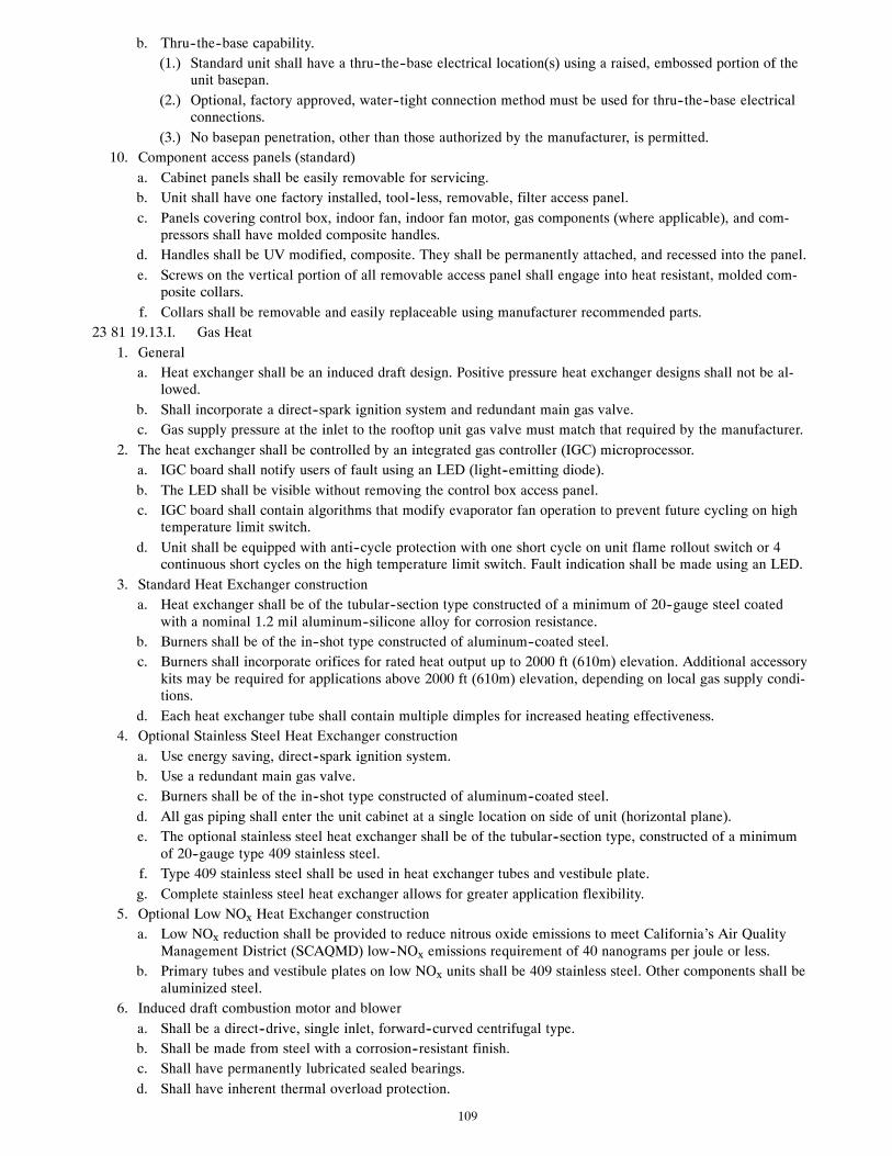
109
b. Thru--the--base capability.(1.) Standard unit shall have a thru--the--base electrical location(s) using a raised, embossed portion of the
unit basepan.(2.) Optional, factory approved, water--tight connection method must be used for thru--the--base electrical
connections.(3.) No basepan penetration, other than those authorized by the manufacturer, is permitted.
10. Component access panels (standard)a. Cabinet panels shall be easily removable for servicing.b. Unit shall have one factory installed, tool--less, removable, filter access panel.c. Panels covering control box, indoor fan, indoor fan motor, gas components (where applicable), and com-
pressors shall have molded composite handles.d. Handles shall be UV modified, composite. They shall be permanently attached, and recessed into the panel.e. Screws on the vertical portion of all removable access panel shall engage into heat resistant, molded com-
posite collars.f. Collars shall be removable and easily replaceable using manufacturer recommended parts.
23 81 19.13.I. Gas Heat1. General
a. Heat exchanger shall be an induced draft design. Positive pressure heat exchanger designs shall not be al-lowed.
b. Shall incorporate a direct--spark ignition system and redundant main gas valve.c. Gas supply pressure at the inlet to the rooftop unit gas valve must match that required by the manufacturer.
2. The heat exchanger shall be controlled by an integrated gas controller (IGC) microprocessor.a. IGC board shall notify users of fault using an LED (light--emitting diode).b. The LED shall be visible without removing the control box access panel.c. IGC board shall contain algorithms that modify evaporator fan operation to prevent future cycling on high
temperature limit switch.d. Unit shall be equipped with anti--cycle protection with one short cycle on unit flame rollout switch or 4
continuous short cycles on the high temperature limit switch. Fault indication shall be made using an LED.3. Standard Heat Exchanger construction
a. Heat exchanger shall be of the tubular--section type constructed of a minimum of 20--gauge steel coatedwith a nominal 1.2 mil aluminum--silicone alloy for corrosion resistance.
b. Burners shall be of the in--shot type constructed of aluminum--coated steel.c. Burners shall incorporate orifices for rated heat output up to 2000 ft (610m) elevation. Additional accessory
kits may be required for applications above 2000 ft (610m) elevation, depending on local gas supply condi-tions.
d. Each heat exchanger tube shall contain multiple dimples for increased heating effectiveness.4. Optional Stainless Steel Heat Exchanger construction
a. Use energy saving, direct--spark ignition system.b. Use a redundant main gas valve.c. Burners shall be of the in--shot type constructed of aluminum--coated steel.d. All gas piping shall enter the unit cabinet at a single location on side of unit (horizontal plane).e. The optional stainless steel heat exchanger shall be of the tubular--section type, constructed of a minimum
of 20--gauge type 409 stainless steel.f. Type 409 stainless steel shall be used in heat exchanger tubes and vestibule plate.g. Complete stainless steel heat exchanger allows for greater application flexibility.
5. Optional Low NOx Heat Exchanger constructiona. Low NOx reduction shall be provided to reduce nitrous oxide emissions to meet California’s Air Quality
Management District (SCAQMD) low--NOx emissions requirement of 40 nanograms per joule or less.b. Primary tubes and vestibule plates on low NOx units shall be 409 stainless steel. Other components shall be
aluminized steel.6. Induced draft combustion motor and blower
a. Shall be a direct--drive, single inlet, forward--curved centrifugal type.b. Shall be made from steel with a corrosion--resistant finish.c. Shall have permanently lubricated sealed bearings.d. Shall have inherent thermal overload protection.

110
e. Shall have an automatic reset feature.23 81 19.13.J. Coils
1. Standard Aluminum Fin -- Copper Tube Coils:a. Standard evaporator and condenser coils shall have aluminum lanced plate fins mechanically bonded to
seamless internally grooved copper tubes with all joints brazed.b. Evaporator coils shall be leak tested to 150 psig, pressure tested to 450 psig, and qualified to UL 1995 burst
test at 1775 psig.c. Condenser coils shall be leak tested to 150 psig, pressure tested to 650 psig, and qualified to UL 1995 burst
test at 1980 psig.2. Optional Pre--coated aluminum--fin condenser coils (3 Phase Models Only):
a. Shall have a durable epoxy--phenolic coating to provide protection in mildly corrosive coastal environ-ments.
b. Coating shall be applied to the aluminum fin stock prior to the fin stamping process to create an inert barri-er between the aluminum fin and copper tube.
c. Epoxy--phenolic barrier shall minimize galvanic action between dissimilar metals.3. Optional Copper--fin evaporator and condenser coils (3 Phase Models Only):
a. Shall be constructed of copper fins mechanically bonded to copper tubes and copper tube sheets.b. Galvanized steel tube sheets shall not be acceptable.c. A polymer strip shall prevent coil assembly from contacting the sheet metal coil pan to minimize potential
for galvanic corrosion between coil and pan.4. Optional E--coated aluminum--fin evaporator and condenser coils (3 Phase Models Only):
a. Shall have a flexible epoxy polymer coating uniformly applied to all coil surface areas without materialbridging between fins.
b. Coating process shall ensure complete coil encapsulation of tubes, fins and headers.c. Color shall be high gloss black with gloss per ASTM D523--89.d. Uniform dry film thickness from 0.8 to 1.2 mil on all surface areas including fin edges.e. Superior hardness characteristics of 2H per ASTM D3363--92A and cross--hatch adhesion of 4B--5B per
ASTM D3359--93.f. Impact resistance shall be up to 160 in.--lb (ASTM D2794--93).g. Humidity and water immersion resistance shall be up to minimum 1000 and 250 hours respectively (ASTM
D2247--92 and ASTM D870--92).h. Corrosion durability shall be confirmed through testing to be no less than 1000 hours salt spray per ASTM
B117--90.5. Standard All Aluminum Novation Coils:
a. Standard condenser coils shall have all aluminum NOVATION Heat Exchanger Technology design consist-ing of aluminum multi port flat tube design and aluminum fin. Coils shall be a furnace brazed design andcontain epoxy lined shrink wrap on all aluminum to copper connections.
b. Condenser coils shall be leak tested to 150 psig, pressure tested to 650 psig, and qualified to UL 1995 bursttest at 1980 psig.
6. Optional E--coated aluminum--fin, aluminum tube condenser coils:a. Shall have a flexible epoxy polymer coating uniformly applied to all coil external surface areas without
material bridging between fins or louvers.b. Coating process shall ensure complete coil encapsulation, including all exposed fin edges.c. E--coat thickness of 0.8 to 1.2 mil with top coat having a uniform dry film thickness from 1.0 to 2.0 mil on
all external coil surface areas, including fin edges, shall be provided.d. Shall have superior hardness characteristics of 2H per ASTM D3363--00 and cross--hatch adhesion of
4B--5B per ASTM D3359--02.e. Shall have superior impact resistance with no cracking, chipping or peeling per NSF/ANSI 51--2002 Method
10.2.23 81 19.13.K. Refrigerant Components
1. Refrigerant circuit shall include the following control, safety, and maintenance features:a. Fixed orifice metering system shall prevent mal--distribution of two--phase refrigerant by including multiple
fixed orifice devices in each refrigeration circuit. Each orifice is to be optimized to the coil circuit it serves.b. Refrigerant filter drier -- Solid core design.c. Service gauge connections on suction and discharge lines.d. Pressure gauge access through a specially designed access port in the top panel of the unit.

111
2. There shall be gauge line access port in the skin of the rooftop, covered by a black, removable plug.a. The plug shall be easy to remove and replace.b. When the plug is removed, the gauge access port shall enable maintenance personnel to route their pressure
gauge lines.c. This gauge access port shall facilitate correct and accurate condenser pressure readings by enabling the
reading with the compressor access panel on.d. The plug shall be made of a leak proof, UV--resistant, composite material.
3. Compressorsa. Unit shall use fully hermetic, scroll compressor for each independent refrigeration circuit.b. Compressor motors shall be cooled by refrigerant gas passing through motor windings.c. Compressors shall be internally protected from high discharge temperature conditions.d. Compressors shall be protected from an over--temperature and over--amperage conditions by an internal,
motor overload device.e. Compressor shall be factory mounted on rubber grommets.f. Compressor motors shall have internal line break thermal, current overload and high pressure differential
protection.g. Crankcase heaters shall not be required for normal operating range, unless required by compressor manufac-
turer due to refrigerant charge limits.23 81 19.13.L. Filter Section
1. Filters access is specified in the unit cabinet section of this specification.2. Filters shall be held in place by a pivoting filter tray, facilitating easy removal and installation.3. Shall consist of factory installed, low velocity, throw--away 2--in. thick fiberglass filters.4. Filters shall be standard, commercially available sizes.5. Only one size filter per unit is allowed.
23 81 19.13.M. Evaporator Fan and Motor1. Evaporator fan motor:
a. Shall have permanently lubricated bearings.b. Shall have inherent automatic--reset thermal overload protection or circuit breaker.c. Shall have a maximum continuous bhp rating for continuous duty operation; no safety factors above that
rating shall be required.2. Belt--driven Evaporator Fan:
a. Belt drive shall include an adjustable pitch motor pulley.b. Shall use sealed, permanently lubricated ball--bearing type.c. Blower fan shall be double--inlet type with forward--curved blades.d. Shall be constructed from steel with a corrosion resistant finish and dynamically balanced.
23 81 19.13.N. Condenser Fans and Motors1. Condenser fan motors:
a. Shall be a totally enclosed motor.b. Shall use permanently lubricated bearings.c. Shall have inherent thermal overload protection with an automatic reset feature.d. Shall use a shaft--down design on 04 to 12 and 16 models and shaft--up on 14 size with rain shield.
2. Condenser Fans:a. Shall be a direct--driven propeller type fan.b. Shall have aluminum blades riveted to corrosion--resistant steel spiders and shall be dynamically balanced.
23 81 19.13.O. Special Features Options and Accessories1. Staged Air Volume System (SAV) for 2--stage cooling models only:
a. Evaporator fan motor:(1.) Shall have permanently lubricated bearings.(2.) Shall have a maximum continuous bhp rating for continuous duty operation; no safety factors above
that rating.(3.) Shall be Variable Frequency duty and 2--speed control.(4.) Shall contain motor shaft grounding ring to prevent electrical bearing fluting damage by safely divert-
ing harmful shaft voltages and bearing currents to ground.
112
2. Variable Frequency Drive (VFD). Only available on 2--speed indoor fan motor option (SAV):a. Shall be installed inside the unit cabinet, mounted, wired and tested.b. Shall contain Electromagnetic Interference (EMI) frequency protection.c. Insulated Gate Bi--Polar Transistors (IGBT) used to produce the output pulse width modulated (PWM)
waveform, allowing for quiet motor operation.d. Self diagnostics with fault and power code LED indicator. Field accessory Display Kit available for further
diagnostics and special setup applications.e. RS485 capability standard.f. Electronic thermal overload protection.g. 5% swinging chokes for harmonic reduction and improved power factor.h. All printed circuit boards shall be conformal coated.
3. Standard Integrated Economizers (Factory installed on 3 Phase Models Only. Field installed on all 3 and 1 PhaseModels):a. Integrated, gear--driven opposing modulating blade design type capable of simultaneous economizer and
compressor operation.b. Independent modules for vertical or horizontal return configurations shall be available. Vertical return mod-
ules shall be available as a factory installed option.c. Damper blades shall be galvanized steel with composite gears. Plastic or composite blades on intake or re-
turn shall not be acceptable.d. Shall include all hardware and controls to provide free cooling with outdoor air when temperature and/or
humidity are below setpoints.e. Shall be equipped with gear driven dampers for both the outdoor ventilation air and the return air for posit-
ive air stream control.f. Standard models shall be equipped with low--leakage dampers, not to exceed 2% leakage at 1 in. wg pres-
sure differential. Economizer controller on electromechanical units shall be Honeywell W7212 thatprovides:(1.) Combined minimum and DCV maximum damper position potentiometers with compressor staging re-
lay.(2.) Functions with solid state analog enthalpy or dry bulb changeover control sensing.(3.) Contain LED indicates for:
when free cooling is availablewhen module is in DCV modewhen exhaust fan contact is closed
g. Ultra low leak EconoMi$er X system shall be available on models with SAV 2--speed Variable FrequencyDrive (VFD) systems. Only available on 2--speed indoor fan motor systems with electromechanical controlsor RTU Open.(1.) Maximum damper leakage rate to be equal to or less than 4.0 cfm/sq. ft. at 1.0 in. w.g., meeting or
exceeding ASHRAE 90.1 requirements. Economizer controller on electromechanical units shall beHoneywell W7220 that provides:
(2.) 2--line LCD interface screen for setup, configuration and troubleshooting(3.) On--board fault detection and diagnostics(4.) Sensor failure loss of communication identification(5.) Automatic sensor detection(6.) Capabilities for use with multiple--speed indoor fan systems(7.) Utilize digital sensors: Dry bulb and Enthalpy
h. Shall be capable of introducing up to 100% outdoor air.i. Shall be equipped with a barometric relief damper capable of relieving up to 100% return air.j. Shall be designed to close damper(s) during loss--of--power situations with spring return built into motor.k. Dry bulb outdoor air temperature sensor shall be provided as standard. Outdoor air sensor setpoint shall be
adjustable and shall range from 40 to 100_F / 4 to 38_C. Additional sensor options shall be available asaccessories.
l. The economizer controller shall also provide control of an accessory power exhaust unit function. Factoryset at 100%, with a range of 0% to 100%.
m. The economizer shall maintain minimum airflow into the building during occupied period and providedesign ventilation rate for full occupancy. A remote potentiometer may be used to override the damper set-point.

113
n. Dampers shall be completely closed when the unit is in the unoccupied mode.o. Economizer controller shall accept a 2--10 Vdc CO2 sensor input for IAQ/DCV control. In this mode,
dampers shall modulate the outdoor air damper to provide ventilation based on the sensor input.p. Compressor lockout sensor shall open at 35_F (2_C) and close closes at 50_F (10_C).q. Actuator shall be direct coupled to economizer gear. No linkage arms or control rods shall be acceptable.r. Economizer controller shall provide indications when in free cooling mode, in the DCV mode, or the ex-
haust fan contact is closed.4. Two--Position Damper (Factory installed on 3 Phase Models Only. Field installed on all 3 and 1 Phase Models)
a. Damper shall be a Two--Position Damper. Damper travel shall be from the full closed position to the fieldadjustable %--open setpoint.
b. Damper shall include adjustable damper travel from 25% to 100% (full open).c. Damper shall include single or dual blade, gear driven dampers and actuator motor.d. Actuator shall be direct coupled to damper gear. No linkage arms or control rods shall be acceptable.e. Damper will admit up to 100% outdoor air for applicable rooftop units.f. Damper shall close upon indoor (evaporator) fan shutoff and/or loss of power.g. The damper actuator shall plug into the rooftop unit’s wiring harness plug. No hard wiring shall be re-
quired.h. Outside air hood shall include aluminum water entrainment filter.
5. Manual dampera. Manual damper package shall consist of damper, air inlet screen, and rain hood which can be preset to ad-
mit up to 25 or 50% outdoor air for year round ventilation.6. Humidi--MiZer Adaptive Dehumidification System (3 Phase Models Only):
a. The Humidi--MiZer Adaptive Dehumidification System shall be factory installed in single stage 48TC04--07and 2--stage 48TC08--16 models with RTPF (round tube plate tin) condenser coils, and shall provide greaterdehumidification of the occupied space by two modes of dehumidification operations in addition to its nor-mal design cooling mode:(1.) Subcooling mode further sub cools the hot liquid refrigerant leaving the condenser coil when both tem-
perature and humidity in the space are not satisfied.(2.) Hot gas reheat mode shall mix a portion of the hot gas from the discharge of the compressor with the
hot liquid refrigerant leaving the condenser coil to create a two--phase heat transfer in the system, res-ulting in a neutral leaving air temperature when only humidity in the space is not satisfied.
(3.) Includes head pressure controller.7. Head Pressure Control Package
a. Controller shall control coil head pressure by condenser fan speed modulation or condenser fan cycling andwind baffles.
b. Shall consist of solid--state control and condenser coil temperature sensor to maintain condensing temperat-ure between 90_F (32_C) and 110_F (43_C) at outdoor ambient temperatures down to --20_F (--29_C).
8. Propane Conversion Kita. Package shall contain all the necessary hardware and instructions to convert a standard natural gas unit for
use with liquefied propane, up to 2000 ft (610m) elevation.b. Additional accessory kits may be required for applications above 2000 ft (610m) elevation.
9. Flue Shield (04--14 sizes only)a. Flue shield shall provide protection from the hot sides of the gas flue hood.
10. Condenser Coil Hail Guard Assembly (Factory installed on 3 Phase Models Only. Field installed on all 3 and 1Phase Models)a. Shall protect against damage from hail.b. Shall be either hood style or louvered.
11. Unit--Mounted, Non--Fused Disconnect Switch (Available on units with MOCP’s of 80 amps or less):a. Switch shall be factory installed, internally mounted.b. National Electric Code (NEC) and UL approved non--fused switch shall provide unit power shutoff.c. Shall be accessible from outside the unit.d. Shall provide local shutdown and lockout capability.
12. Convenience Outlet:a. Powered convenience outlet. (3 Phase Models Only)
(1.) Outlet shall be powered from main line power to the rooftop unit.

114
(2.) Outlet shall be powered from line side or load side of disconnect by installing contractor, as requiredby code. If outlet is powered from load side of disconnect, unit electrical ratings shall be UL certifiedand rated for additional outlet amperage.
(3.) Outlet shall be factory installed and internally mounted with easily accessible 115--v female receptacle.(4.) Outlet shall include 15 amp GFI receptacles with independent fuse protection.(5.) Voltage required to operate convenience outlet shall be provided by a factory installed step--down
transformer.(6.) Outlet shall be accessible from outside the unit.(7.) Outlet shall include a field installed “Wet in Use” cover.
b. Non--Powered convenience outlet.(1.) Outlet shall be powered from a separate 115/120v power source.(2.) A transformer shall not be included.(3.) Outlet shall be factory installed and internally mounted with easily accessible 115--v female receptacle.(4.) Outlet shall include 15 amp GFI receptacles with independent fuse protection.(5.) Outlet shall be accessible from outside the unit.(6.) Outlet shall include a field installed “Wet in Use” cover.
13. Flue Discharge Deflector (04--14 sizes only):a. Flue discharge deflector shall direct unit exhaust vertically instead of horizontally.b. Deflector shall be defined as a “natural draft” device by the National Fuel and Gas (NFG) code.
14. Thru--the--Base Connectors:a. Kits shall provide connectors to permit gas and electrical connections to be brought to the unit through the
unit basepan.b. Minimum of four connection locations per unit.
15. Supply Duct Cover: (16 size only.)a. Required when field converting the factory standard vertical duct supply to horizontal duct supply configur-
ation. One required per unit.16. Propeller Power Exhaust:
a. Power exhaust shall be used in conjunction with an integrated economizer.b. Independent modules for vertical or horizontal return configurations shall be available.c. Horizontal power exhaust is shall be mounted in return ductwork.d. Power exhaust shall be controlled by economizer controller operation. Exhaust fans shall be energized when
dampers open past the 0--100% adjustable setpoint on the economizer control.17. Roof Curbs (Vertical):
a. Full perimeter roof curb with exhaust capability providing separate air streams for energy recovery from theexhaust air without supply air contamination.
b. Formed galvanized steel with wood nailer strip and shall be capable of supporting entire unit weight.c. Permits installation and securing of ductwork to curb prior to mounting unit on the curb.
18. High Altitude Gas Conversion Kit:a. Package shall contain all the necessary hardware and instructions to convert a standard natural gas unit to
operate from 2000--7000 ft (610 to 2134m) elevation with natural gas or from 0--7000 ft (90--2134m) eleva-tion with liquefied propane.
19. Outdoor Air Enthalpy Sensor:a. The outdoor air enthalpy sensor shall be used to provide single enthalpy control. When used in conjunction
with a return air enthalpy sensor, the unit will provide differential enthalpy control. The sensor allows theunit to determine if outside air is suitable for free cooling.
20. Return Air Enthalpy Sensor:a. The return air enthalpy sensor shall be used in conjunction with an outdoor air enthalpy sensor to provide
differential enthalpy control.21. Indoor Air Quality (CO2) Sensor:
a. Shall be able to provide demand ventilation indoor air quality (IAQ) control.b. The IAQ sensor shall be available in duct mount, wall mount, or wall mount with LED display. The set-
point shall have adjustment capability.22. Smoke detectors (factory installed only):
a. Shall be a Four--Wire Controller and Detector.b. Shall be environmental compensated with differential sensing for reliable, stable, and drift--free sensitivity.

115
c. Shall use magnet--activated test/reset sensor switches.d. Shall have tool--less connection terminal access.e. Shall have a recessed momentary switch for testing and resetting the detector.f. Controller shall include:
(1.) One set of normally open alarm initiation contacts for connection to an initiating device circuit on afire alarm control panel.
(2.) Two Form--C auxiliary alarm relays for interface with rooftop unit or other equipment.(3.) One Form--C supervision (trouble) relay to control the operation of the Trouble LED on a remote test/
reset station.(4.) Capable of direct connection to two individual detector modules.(5.) Can be wired to up to 14 other duct smoke detectors for multiple fan shutdown applications
23. Winter start kita. Shall contain a bypass device around the low pressure switch.b. Shall be required when mechanical cooling is required down to 25_F (--4_C).c. Shall not be required to operate on an economizer when below an outdoor ambient of 40_F (4_C).
24. Time Guarda. Shall prevent compressor short--cycling by providing a 5--minute delay (±2 minutes) before restarting a
compressor after shutdown for any reason.b. One device shall be required per compressor.
25. Disconnect Switch Bracket (16 size only)a. Provides a pre--engineered and sized mounting bracket for applications requiring a unit mounted fused and
non--fused disconnect of greater than 100 amps. Bracket assures that no damage will occur to coils whenmounting with screws and other fasteners.
26. California OSHPD Seismic Certification Labela. Units meet the seismic capacity requirements of the International Code Council Evaluation Service (ICC--
ES) document AC156 (Acceptance Criteria for Seismic Qualification by Shake--Table Testing of Nonstruc-tural Components and Systems) and per International Building Code (IBC 2009) at an SDS (g) value of2.00 z/h=1.0, Ip=1.5 and certified by independent structural engineers.
b. Units shall include a certification label that meets the CA OSHPD Special Seismic Certification pre--ap-proval labeling requirements on the external chassis of the unit.
27. Hinged Access Panelsa. Shall provide easy access through integrated quarter turn latches.b. Shall be on major panels of: filter, control box, fan motor, and compressor.
28. Display Kit for Variable Frequency Drivea. Kit allows the ability to access the VFD controller programs to provide special setup capabilities and dia-
gnostics.b. Kit contains display module, mounting bracket and communication cable.c. Display Kit can be permanently installed in the unit or used on any SAV system VFD controller as needed.

116
Copyright 2012 Carrier Corp. S 7310 W. Morris St. S Indianapolis, IN 46231 Edition Date: 08/12
Manufacturer reserves the right to change, at any time, specifications and designs without notice and without obligations.
Catalog No: 48TC---19PD
Replaces: 48TC---17PD