Embed Size (px)
Citation preview
1
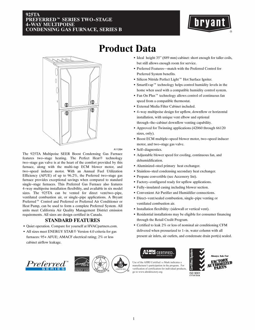
925TAPREFERREDt SERIES TWO--STAGE4--WAY MULTIPOISECONDENSING GAS FURNACE, SERIES B
Product Data
A11264
The 925TA Multipoise SEER Boost Condensing Gas Furnacefeatures two--stage heating. The Perfect HeatR technologytwo--stage gas valve is at the heart of the comfort provided by thisfurnace, along with the multi--tap ECM blower motor, andtwo--speed inducer motor. With an Annual Fuel UtilizationEfficiency (AFUE) of up to 96.2%, the Preferred two--stage gasfurnace provides exceptional savings when compared to standardsingle--stage furnaces. This Preferred Gas Furnace also features4--way multipoise installation flexibility, and available in six modelsizes. The 925TA can be vented for direct vent/two--pipe,ventilated combustion air, or single--pipe applications. A BryantPreferred Control and Preferred or Preferred Air Conditioner orHeat Pump, can be used to form a complete Preferred System. Allunits meet California Air Quality Management District emissionrequirements. All sizes are design certified in Canada.
STANDARD FEATURESS Quiet operation. Compare for yourself at HVACpartners.com.
S All sizes meet ENERGY STARR Version 4.0 criteria for gas
furnaces: 95+ AFUE; AMACF electrical rating; 2% or less
cabinet airflow leakage.
S Ideal height 35” (889 mm) cabinet: short enough for taller coils,
but still allows enough room for service.
S Preferred Features—match with the Preferred Control for
Preferred System benefits.
S Silicon Nitride Perfect Light Hot Surface Igniter.
S SmartEvap technology helps control humidity levels in the
home when used with a compatible humidity control system.
S Fan On Plus technology allows control of continuous fan
speed from a compatible thermostat.
S External Media Filter Cabinet included.
S 4--way multipoise design for upflow, downflow or horizontal
installation, with unique vent elbow and optional
through--the--cabinet downflow venting capability.
S Approved for Twinning applications (42060 through 66120
sizes, only).
S Boost ECM multiple--speed blower motor, two--speed inducer
motor, and two--stage gas valve.
S Self--diagnostics.
S Adjustable blower speed for cooling, continuous fan, and
dehumidification.
S Aluminized--steel primary heat exchanger.
S Stainless--steel condensing secondary heat exchanger.
S Propane convertible (see Accessory list).
S Factory--configured ready for upflow applications.
S Fully--insulated casing including blower section.
S Convenient Air Purifier and Humidifier connections.
S Direct--vent/sealed combustion, single--pipe venting or
ventilated combustion air.
S Installation flexibility: (sidewall or vertical vent).
S Residential installations may be eligible for consumer financing
through the Retail Credit Program.
S Certified to leak 2% or less of nominal air conditioning CFM
delivered when pressurized to 1--in. water column with all
present air inlets, air outlets, and condensate drain port(s) sealed.
CERTIFIED
Always Ask For
Use of the AHRI Certified TM Mark indicates amanufacturer’s participation in the program. Forverification of certification for individual products,go to www.ahridirectory.org.
2
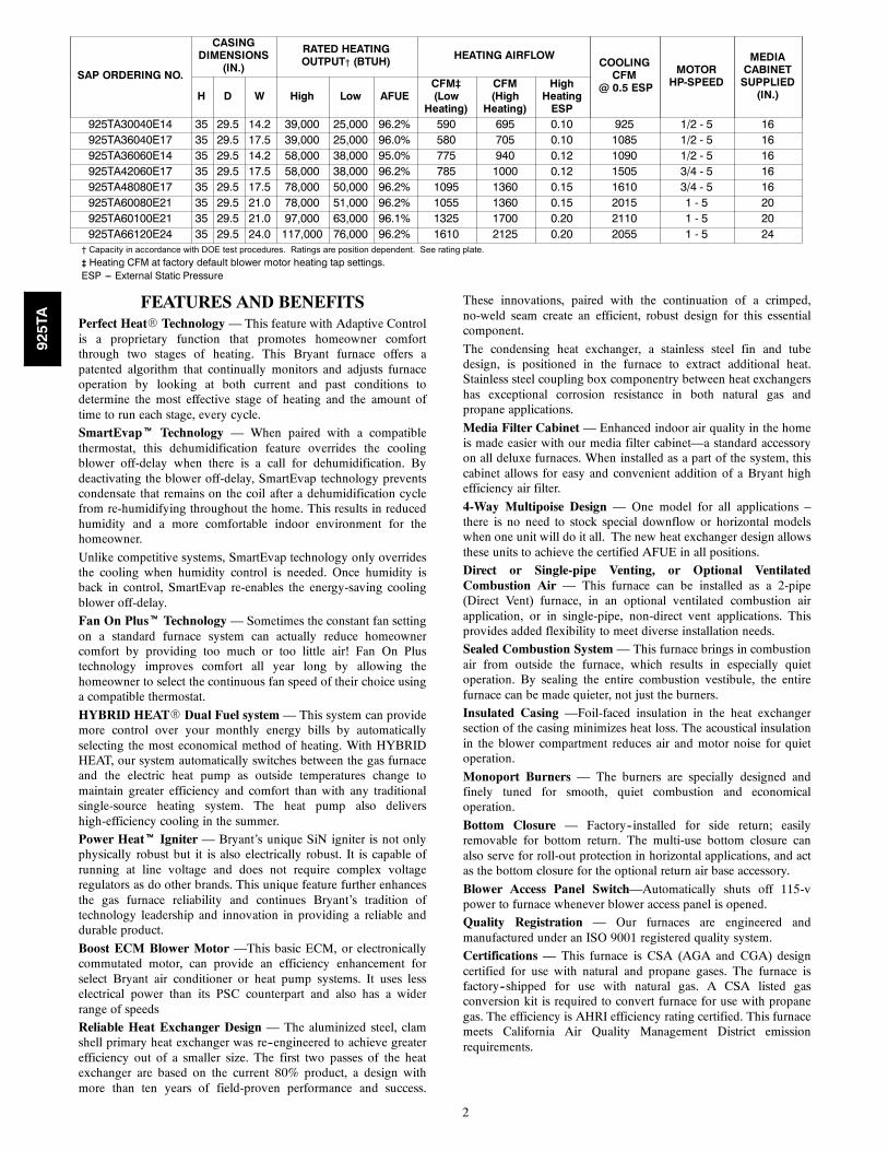
SAP ORDERING NO.
CASINGDIMENSIONS
(IN.)
RATED HEATINGOUTPUT† (BTUH) HEATING AIRFLOW
COOLINGCFM
@ 0.5 ESP
MOTORHP-SPEED
MEDIACABINETSUPPLIED(IN.)H D W High Low AFUE
CFM‡(LowHeating)
CFM(HighHeating)
HighHeatingESP
925TA30040E14 35 29.5 14.2 39,000 25,000 96.2% 590 695 0.10 925 1/2 - 5 16925TA36040E17 35 29.5 17.5 39,000 25,000 96.0% 580 705 0.10 1085 1/2 - 5 16925TA36060E14 35 29.5 14.2 58,000 38,000 95.0% 775 940 0.12 1090 1/2 - 5 16925TA42060E17 35 29.5 17.5 58,000 38,000 96.2% 785 1000 0.12 1505 3/4 - 5 16925TA48080E17 35 29.5 17.5 78,000 50,000 96.2% 1095 1360 0.15 1610 3/4 - 5 16925TA60080E21 35 29.5 21.0 78,000 51,000 96.2% 1055 1360 0.15 2015 1 - 5 20925TA60100E21 35 29.5 21.0 97,000 63,000 96.1% 1325 1700 0.20 2110 1 - 5 20925TA66120E24 35 29.5 24.0 117,000 76,000 96.2% 1610 2125 0.20 2055 1 - 5 24
† Capacity in accordance with DOE test procedures. Ratings are position dependent. See rating plate.
‡ Heating CFM at factory default blower motor heating tap settings.ESP --- External Static Pressure
FEATURES AND BENEFITSPerfect HeatR Technology — This feature with Adaptive Controlis a proprietary function that promotes homeowner comfortthrough two stages of heating. This Bryant furnace offers apatented algorithm that continually monitors and adjusts furnaceoperation by looking at both current and past conditions todetermine the most effective stage of heating and the amount oftime to run each stage, every cycle.
SmartEvapt Technology — When paired with a compatiblethermostat, this dehumidification feature overrides the coolingblower off-delay when there is a call for dehumidification. Bydeactivating the blower off-delay, SmartEvap technology preventscondensate that remains on the coil after a dehumidification cyclefrom re-humidifying throughout the home. This results in reducedhumidity and a more comfortable indoor environment for thehomeowner.
Unlike competitive systems, SmartEvap technology only overridesthe cooling when humidity control is needed. Once humidity isback in control, SmartEvap re-enables the energy-saving coolingblower off-delay.
Fan On Plust Technology — Sometimes the constant fan settingon a standard furnace system can actually reduce homeownercomfort by providing too much or too little air! Fan On Plustechnology improves comfort all year long by allowing thehomeowner to select the continuous fan speed of their choice usinga compatible thermostat.
HYBRID HEATR Dual Fuel system — This system can providemore control over your monthly energy bills by automaticallyselecting the most economical method of heating. With HYBRIDHEAT, our system automatically switches between the gas furnaceand the electric heat pump as outside temperatures change tomaintain greater efficiency and comfort than with any traditionalsingle-source heating system. The heat pump also delivershigh-efficiency cooling in the summer.
Power Heatt Igniter — Bryant’s unique SiN igniter is not onlyphysically robust but it is also electrically robust. It is capable ofrunning at line voltage and does not require complex voltageregulators as do other brands. This unique feature further enhancesthe gas furnace reliability and continues Bryant’s tradition oftechnology leadership and innovation in providing a reliable anddurable product.
Boost ECM Blower Motor —This basic ECM, or electronicallycommutated motor, can provide an efficiency enhancement forselect Bryant air conditioner or heat pump systems. It uses lesselectrical power than its PSC counterpart and also has a widerrange of speeds
Reliable Heat Exchanger Design — The aluminized steel, clamshell primary heat exchanger was re--engineered to achieve greaterefficiency out of a smaller size. The first two passes of the heatexchanger are based on the current 80% product, a design withmore than ten years of field-proven performance and success.
These innovations, paired with the continuation of a crimped,no-weld seam create an efficient, robust design for this essentialcomponent.
The condensing heat exchanger, a stainless steel fin and tubedesign, is positioned in the furnace to extract additional heat.Stainless steel coupling box componentry between heat exchangershas exceptional corrosion resistance in both natural gas andpropane applications.
Media Filter Cabinet — Enhanced indoor air quality in the homeis made easier with our media filter cabinet—a standard accessoryon all deluxe furnaces. When installed as a part of the system, thiscabinet allows for easy and convenient addition of a Bryant highefficiency air filter.
4-Way Multipoise Design — One model for all applications –there is no need to stock special downflow or horizontal modelswhen one unit will do it all. The new heat exchanger design allowsthese units to achieve the certified AFUE in all positions.
Direct or Single-pipe Venting, or Optional VentilatedCombustion Air — This furnace can be installed as a 2-pipe(Direct Vent) furnace, in an optional ventilated combustion airapplication, or in single-pipe, non-direct vent applications. Thisprovides added flexibility to meet diverse installation needs.
Sealed Combustion System — This furnace brings in combustionair from outside the furnace, which results in especially quietoperation. By sealing the entire combustion vestibule, the entirefurnace can be made quieter, not just the burners.
Insulated Casing —Foil-faced insulation in the heat exchangersection of the casing minimizes heat loss. The acoustical insulationin the blower compartment reduces air and motor noise for quietoperation.
Monoport Burners — The burners are specially designed andfinely tuned for smooth, quiet combustion and economicaloperation.
Bottom Closure — Factory--installed for side return; easilyremovable for bottom return. The multi-use bottom closure canalso serve for roll-out protection in horizontal applications, and actas the bottom closure for the optional return air base accessory.
Blower Access Panel Switch—Automatically shuts off 115-vpower to furnace whenever blower access panel is opened.
Quality Registration — Our furnaces are engineered andmanufactured under an ISO 9001 registered quality system.
Certifications — This furnace is CSA (AGA and CGA) designcertified for use with natural and propane gases. The furnace isfactory--shipped for use with natural gas. A CSA listed gasconversion kit is required to convert furnace for use with propanegas. The efficiency is AHRI efficiency rating certified. This furnacemeets California Air Quality Management District emissionrequirements.
925TA
3
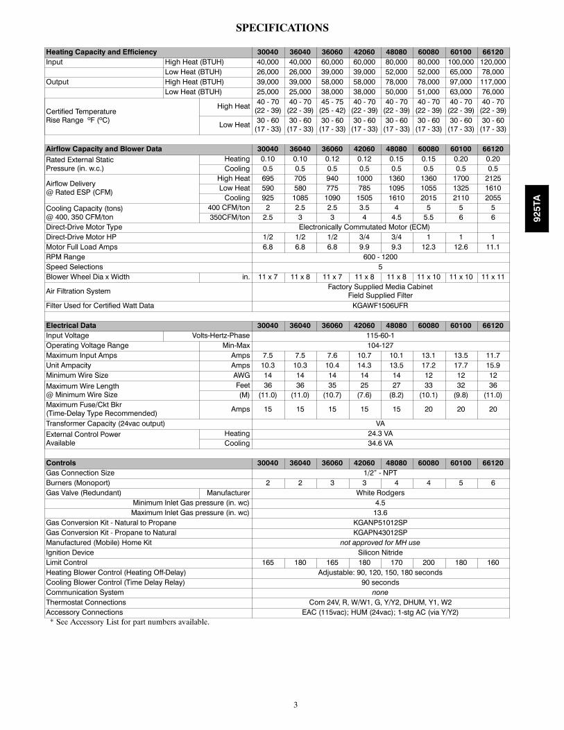
SPECIFICATIONS
Heating Capacity and Efficiency 30040 36040 36060 42060 48080 60080 60100 66120Input High Heat (BTUH) 40,000 40,000 60,000 60,000 80,000 80,000 100,000 120,000
Low Heat (BTUH) 26,000 26,000 39,000 39,000 52,000 52,000 65,000 78,000Output High Heat (BTUH) 39,000 39,000 58,000 58,000 78,000 78,000 97,000 117,000
Low Heat (BTUH) 25,000 25,000 38,000 38,000 50,000 51,000 63,000 76,000
Certified TemperatureRise Range ºF (ºC)
High Heat 40 - 70(22 - 39)40 - 70(22 - 39)
45 - 75(25 - 42)
40 - 70(22 - 39)
40 - 70(22 - 39)
40 - 70(22 - 39)
40 - 70(22 - 39)
40 - 70(22 - 39)
Low Heat 30 - 60(17 - 33)30 - 60(17 - 33)
30 - 60(17 - 33)
30 - 60(17 - 33)
30 - 60(17 - 33)
30 - 60(17 - 33)
30 - 60(17 - 33)
30 - 60(17 - 33)
Airflow Capacity and Blower Data 30040 36040 36060 42060 48080 60080 60100 66120Rated External StaticPressure (in. w.c.)
Heating 0.10 0.10 0.12 0.12 0.15 0.15 0.20 0.20Cooling 0.5 0.5 0.5 0.5 0.5 0.5 0.5 0.5
Airflow Delivery@ Rated ESP (CFM)
High Heat 695 705 940 1000 1360 1360 1700 2125Low Heat 590 580 775 785 1095 1055 1325 1610Cooling 925 1085 1090 1505 1610 2015 2110 2055
Cooling Capacity (tons)@ 400, 350 CFM/ton
400 CFM/ton 2 2.5 2.5 3.5 4 5 5 5350CFM/ton 2.5 3 3 4 4.5 5.5 6 6
Direct-Drive Motor Type Electronically Commutated Motor (ECM)Direct-Drive Motor HP 1/2 1/2 1/2 3/4 3/4 1 1 1Motor Full Load Amps 6.8 6.8 6.8 9.9 9.3 12.3 12.6 11.1RPM Range 600 - 1200Speed Selections 5Blower Wheel Dia x Width in. 11 x 7 11 x 8 11 x 7 11 x 8 11 x 8 11 x 10 11 x 10 11 x 11
Air Filtration System Factory Supplied Media CabinetField Supplied Filter
Filter Used for Certified Watt Data KGAWF1506UFR
Electrical Data 30040 36040 36060 42060 48080 60080 60100 66120Input Voltage Volts-Hertz-Phase 115-60-1Operating Voltage Range Min-Max 104-127Maximum Input Amps Amps 7.5 7.5 7.6 10.7 10.1 13.1 13.5 11.7Unit Ampacity Amps 10.3 10.3 10.4 14.3 13.5 17.2 17.7 15.9Minimum Wire Size AWG 14 14 14 14 14 12 12 12Maximum Wire Length@ Minimum Wire Size
Feet 36 36 35 25 27 33 32 36(M) (11.0) (11.0) (10.7) (7.6) (8.2) (10.1) (9.8) (11.0)
Maximum Fuse/Ckt Bkr(Time-Delay Type Recommended) Amps 15 15 15 15 15 20 20 20
Transformer Capacity (24vac output) VAExternal Control PowerAvailable
Heating 24.3 VACooling 34.6 VA
Controls 30040 36040 36060 42060 48080 60080 60100 66120Gas Connection Size 1/2” - NPTBurners (Monoport) 2 2 3 3 4 4 5 6Gas Valve (Redundant) Manufacturer White Rodgers
Minimum Inlet Gas pressure (in. wc) 4.5Maximum Inlet Gas pressure (in. wc) 13.6
Gas Conversion Kit - Natural to Propane KGANP51012SPGas Conversion Kit - Propane to Natural KGAPN43012SPManufactured (Mobile) Home Kit not approved for MH useIgnition Device Silicon NitrideLimit Control 165 180 165 180 170 200 180 160Heating Blower Control (Heating Off-Delay) Adjustable: 90, 120, 150, 180 secondsCooling Blower Control (Time Delay Relay) 90 secondsCommunication System noneThermostat Connections Com 24V, R, W/W1, G, Y/Y2, DHUM, Y1, W2Accessory Connections EAC (115vac); HUM (24vac); 1-stg AC (via Y/Y2)* See Accessory List for part numbers available.
925TA
4
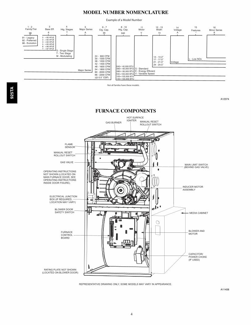
MODEL NUMBER NOMENCLATURE
98 6 T A 30 040 V 14 A -- A
S - Single StageT - Two StageM - Modulating
S - StandardE - Energy EfficientV - Variable Speed
14 - 14.2”17 - 17.5”21 - 21.0”24 - 24.5”
91 - Legacy92 - Preferred98 - Evolution
VoltageL - Low NOx
1 - 2Family/Tier
3Base Eff. Htg. Stages
4 5Major Series
6 - 7Clg. Cap. Htg. Cap.
8 - 10Motor
11 12 - 13Width
14Voltage
15Features Minor Series
16
Major Series
24 - 800 CFM30 - 1000 CFM36 - 1200 CFM42 - 1400 CFM48 - 1600 CFM54 - 1800 CFM60 - 2000 CFM66 - 2200 CFM(@ 0.5” ESP)
040= 40,000 BTU 060= 60,000 BTU 080= 80,000 BTU 100=100,000 BTU 120=120,000 BTU140=140,000 BTU
Not all familes have these models.
0 - +90 AFUE2 - +92 AFUE3 - +93 AFUE5 - +95 AFUE6 - +96 AFUE7 - +97 AFUE
Example of a Model Number
A12374
FURNACE COMPONENTS
RATING PLATE NOT SHOWN(LOCATED ON BLOWER DOOR)
GAS VALVEMAIN LIMIT SWITCH(BEHIND GAS VALVE)
REPRESENTATIVE DRAWING ONLY, SOME MODELS MAY VARY IN APPEARANCE.
ELECTRICAL JUNCTIONBOX (IF REQUIRED, LOCATION MAY VARY)
MEDIA CABINET
OPERATING INSTRUCTIONSNOT SHOWN (LOCATED ONMAIN FURNACE DOOR, SEE OPERATING INSTRUCTIONS INSIDE DOOR FIGURE).
FURNACECONTROLBOARD
MANUAL RESETROLLOUT SWITCH
FLAMESENSOR
MANUAL RESETROLLOUT SWITCH
GAS BURNER
HOT SURFACEIGNITER
INDUCER MOTORASSEMBLY
BLOWER ANDMOTOR
CAPACITOR/POWER CHOKE(IF USED)
BLOWER DOORSAFETY SWITCH
A11408
925TA
5
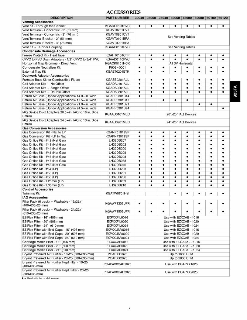
ACCESSORIESDESCRIPTION PART NUMBER 30040 36060 36040 42060 48080 60080 60100 66120
Venting AccessoriesVent Kit - Through the Cabinet KGADC0101BVC D D D D D D D D
Vent Terminal - Concentric - 2” (51 mm) KGAVT0701CVT
See Venting TablesVent Terminal - Concentric - 3” (76 mm) KGAVT0801CVTVent Terminal Bracket - 2” (51 mm) KGAVT0101BRAVent Terminal Bracket - 3” (76 mm) KGAVT0201BRAVent Kit --- Rubber Coupling KGAAC0101RVC See Venting TablesCondensate Drainage AccessoriesFreeze Protect Kit - Heat Tape KGAHT0101CFP D D D D D D D D
CPVC to PVC Drain Adapters - 1/2” CPVC to 3/4” PVC KGAAD0110PVC D D D D D D D D
Horizontal Trap Grommet - Direct Vent KGACK0101HCK All DV HorizontalCondensate Neutralizer Kit P908---0001 D D D D D D D D
External Trap Kit KGAET0201ETK D D D D D D D D
Ductwork Adapter AccessoriesFurnace Base Kit for Combustible Floors KGASB0201ALL D D D D D D D D
Coil Adapter Kits --- No Offset KGADA0101ALL D D D D D D D D
Coil Adapter Kits --- Single Offset KGADA0201ALL D D D D D D D D
Coil Adapter Kits --- Double Offset KGADA0301ALL D D D D D D D D
Return Air Base (Upflow Applications) 14.0--- in. wide KGARP0301B14 D D
Return Air Base (Upflow Applications) 17.5--- in. wide KGARP0301B17 D D D
Return Air Base (Upflow Applications) 21.0--- in. wide KGARP0301B21 D D
Return Air Base (Upflow Applications) 24.5--- in. wide KGARP0301B24 D
IAQ Device Duct Adapters 20.0--- in. IAQ to 16 in. SideReturn KGAAD0101MEC 20”x25” IAQ Devices
IAQ Device Duct Adapters 24.0--- in. IAQ to 16 in. SideReturn KGAAD0201MEC 24”x25” IAQ Devices
Gas Conversion AccessoriesGas Conversion Kit - Nat to LP KGANP51012SP D D D D D D D D
Gas Conversion Kit - LP to Nat KGAPN43012SP D D D D D D D D
Gas Orifice Kit - #42 (Nat Gas) LH32DB207 D D D D D D D D
Gas Orifice Kit - #43 (Nat Gas) LH32DB202 D D D D D D D D
Gas Orifice Kit - #44 (Nat Gas) LH32DB200 D D D D D D D D
Gas Orifice Kit - #45 (Nat Gas) LH32DB205 D D D D D D D D
Gas Orifice Kit - #46 (Nat Gas) LH32DB208 D D D D D D D D
Gas Orifice Kit - #47 (Nat Gas) LH32DB078 D D D D D D D D
Gas Orifice Kit - #48 (Nat Gas) LH32DB076 D D D D D D D D
Gas Orifice Kit - #54 (LP) LH32DB203 D D D D D D D D
Gas Orifice Kit - #55 (LP) LH32DB201 D D D D D D D D
Gas Orifice Kit - #56 (LP) LH32DB206 D D D D D D D D
Gas Orifice Kit - 1.25mm (LP) LH32DB209 D D D D D D D D
Gas Orifice Kit - 1.30mm (LP) LH32DB210 D D D D D D D D
Control AccessoriesTwinning Kit KGATW0701HSI D D D D D
IAQ AccessoriesFilter Pack (6 pack) --- Washable - 16x25x1(406x635x25 mm) KGAWF1306UFR D D D D D D D D
Filter Pack (6 pack) --- Washable - 24x25x1(610x635x25 mm) KGAWF1506UFR D D D D D D D D
EZ-Flex Filter - 16” (406 mm) EXPXXFIL0016 Use with EZXCAB---1016EZ-Flex Filter - 20” (508 mm) EXPXXFIL0020 Use with EZXCAB---1020EZ-Flex Filter - 24” (610 mm) EXPXXFIL0024 Use with EZXCAB---1024EZ-Flex Filter with End Caps - 16” (406 mm) EXPXXUNV0016 Use with EZXCAB---1016EZ-Flex Filter with End Caps - 20” (508 mm) EXPXXUNV0020 Use with EZXCAB---1020EZ-Flex Filter with End Caps - 24” (610 mm) EXPXXUNV0024 Use with EZXCAB---1024Cartridge Media Filter - 16” (406 mm) FILXXCAR0016 Use with FILCABXL---1016Cartridge Media Filter - 20” (508 mm) FILXXCAR0020 Use with FILCABXL---1020Cartridge Media Filter - 24” (610 mm) FILXXCAR0024 Use with FILCABXL---1024Bryant Preferred Air Purifier - 16x25 (508x635 mm) PGAPXX1625 Up to 1600 CFMBryant Preferred Air Purifier - 20x25 (508x635 mm) PGAPXX2025 Up to 2000 CFMBryant Preferred Air Purifier Repl Filter - 16x25(406x635 mm) PGAPAXXCAR1625 Use with PGAPXX1625
Bryant Preferred Air Purifier Repl. Filter - 20x25(508x635 mm) PGAPAXXCAR2025 Use with PGAPXX2025
D = Used with the model furnace
925TA
6
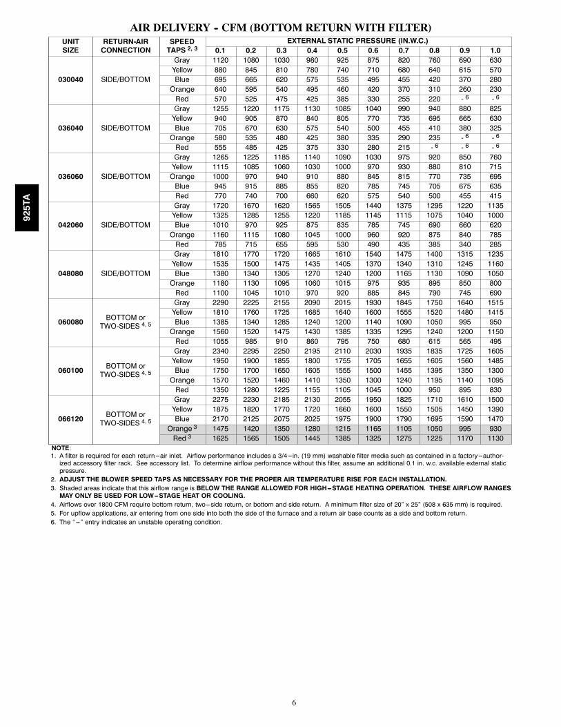
AIR DELIVERY -- CFM (BOTTOM RETURN WITH FILTER)UNITSIZE
RETURN-AIRCONNECTION
SPEEDTAPS 2, 3
EXTERNAL STATIC PRESSURE (IN.W.C.)0.1 0.2 0.3 0.4 0.5 0.6 0.7 0.8 0.9 1.0
030040 SIDE/BOTTOM
Gray 1120 1080 1030 980 925 875 820 760 690 630Yellow 880 845 810 780 740 710 680 640 615 570Blue 695 665 620 575 535 495 455 420 370 280Orange 640 595 540 495 460 420 370 310 260 230Red 570 525 475 425 385 330 255 220 - 6 - 6
036040 SIDE/BOTTOM
Gray 1255 1220 1175 1130 1085 1040 990 940 880 825Yellow 940 905 870 840 805 770 735 695 665 630Blue 705 670 630 575 540 500 455 410 380 325Orange 580 535 480 425 380 335 290 235 - 6 - 6
Red 555 485 425 375 330 280 215 - 6 - 6 - 6
036060 SIDE/BOTTOM
Gray 1265 1225 1185 1140 1090 1030 975 920 850 760Yellow 1115 1085 1060 1030 1000 970 930 880 810 715Orange 1000 970 940 910 880 845 815 770 735 695Blue 945 915 885 855 820 785 745 705 675 635Red 770 740 700 660 620 575 540 500 455 415
042060 SIDE/BOTTOM
Gray 1720 1670 1620 1565 1505 1440 1375 1295 1220 1135Yellow 1325 1285 1255 1220 1185 1145 1115 1075 1040 1000Blue 1010 970 925 875 835 785 745 690 660 620Orange 1160 1115 1080 1045 1000 960 920 875 840 785Red 785 715 655 595 530 490 435 385 340 285
048080 SIDE/BOTTOM
Gray 1810 1770 1720 1665 1610 1540 1475 1400 1315 1235Yellow 1535 1500 1475 1435 1405 1370 1340 1310 1245 1160Blue 1380 1340 1305 1270 1240 1200 1165 1130 1090 1050Orange 1180 1130 1095 1060 1015 975 935 895 850 800Red 1100 1045 1010 970 920 885 845 790 745 690
060080 BOTTOM orTWO-SIDES 4, 5
Gray 2290 2225 2155 2090 2015 1930 1845 1750 1640 1515Yellow 1810 1760 1725 1685 1640 1600 1555 1520 1480 1415Blue 1385 1340 1285 1240 1200 1140 1090 1050 995 950Orange 1560 1520 1475 1430 1385 1335 1295 1240 1200 1150Red 1055 985 910 860 795 750 680 615 565 495
060100 BOTTOM orTWO-SIDES 4, 5
Gray 2340 2295 2250 2195 2110 2030 1935 1835 1725 1605Yellow 1950 1900 1855 1800 1755 1705 1655 1605 1560 1485Blue 1750 1700 1650 1605 1555 1500 1455 1395 1350 1300Orange 1570 1520 1460 1410 1350 1300 1240 1195 1140 1095Red 1350 1280 1225 1155 1105 1045 1000 950 895 830
066120 BOTTOM orTWO-SIDES 4, 5
Gray 2275 2230 2185 2130 2055 1950 1825 1710 1610 1500Yellow 1875 1820 1770 1720 1660 1600 1550 1505 1450 1390Blue 2170 2125 2075 2025 1975 1900 1790 1695 1590 1470
Orange 3 1475 1420 1350 1280 1215 1165 1105 1050 995 930Red 3 1625 1565 1505 1445 1385 1325 1275 1225 1170 1130
NOTE:1. A filter is required for each return ---air inlet. Airflow performance includes a 3/4---in. (19 mm) washable filter media such as contained in a factory---author-ized accessory filter rack. See accessory list. To determine airflow performance without this filter, assume an additional 0.1 in. w.c. available external staticpressure.
2. ADJUST THE BLOWER SPEED TAPS AS NECESSARY FOR THE PROPER AIR TEMPERATURE RISE FOR EACH INSTALLATION.3. Shaded areas indicate that this airflow range is BELOW THE RANGE ALLOWED FOR HIGH---STAGE HEATING OPERATION. THESE AIRFLOW RANGESMAY ONLY BE USED FOR LOW---STAGE HEAT OR COOLING.
4. Airflows over 1800 CFM require bottom return, two---side return, or bottom and side return. A minimum filter size of 20” x 25” (508 x 635 mm) is required.5. For upflow applications, air entering from one side into both the side of the furnace and a return air base counts as a side and bottom return.6. The “---” entry indicates an unstable operating condition.
925TA
7
MAXIMUM ALLOWABLE EXPOSED VENT LENGTHS INSULATION TABLE -- FT. / M
Two StageFurnace HighHeat Input
Winter DesignTemp ° F (° C)
PipeLength inFt. & M
No Insulation 3/8-in. (9.5 mm) 1/2-in. (12.7 mm)
Pipe Diameter-inches (mm) Pipe Diameter-inches (mm) Pipe Diameter-inches (mm)
1.5 2.0 2.5 3.0 4.0 1.5 2.0 2.5 3.0 4.0 1.5 2.0 2.5 3.0 4.0
(38) (51) (64) (76) (102) (38) (51) (64) (76) (102) (38) (51) (64) (76) (102)
40000*
20 (-10)Ft. 40.0 35.0 35.0 N/A N/A 50.0 104.0 94.0 N/A N/A 50.0 122.0 110.0 N/A N/A
M 12.2 10.7 10.7 N/A N/A 15.2 31.7 28.7 N/A N/A 15.2 37.2 33.5 N/A N/A
0 (-20)Ft. 19.0 14.0 12.0 N/A N/A 50.0 61.0 54.0 N/A N/A 50.0 74.0 65.0 N/A N/A
M 5.8 4.3 3.7 N/A N/A 15.2 18.6 16.5 N/A N/A 15.2 22.6 19.8 N/A N/A
-20 (-30)Ft. 9.0 3.0 1.0 N/A N/A 50.0 41.0 35.0 N/A N/A 50.0 51.0 43.0 N/A N/A
M 2.7 0.9 0.3 N/A N/A 15.2 12.5 10.7 N/A N/A 15.2 15.5 13.1 N/A N/A
-40 (-40)Ft. 3.0 0.0 0.0 N/A N/A 39.0 29.0 23.0 N/A N/A 48.0 37.0 30.0 N/A N/A
M 0.9 0.0 0.0 N/A N/A 11.9 8.8 7.0 N/A N/A 14.6 11.3 9.1 N/A N/A
60000
20 (-10)Ft. 30.0 51.0 51.0 45.0 N/A 30.0 135.0 138.0 120.0 N/A 30.0 135.0 162.0 141.0 N/A
M 9.1 15.5 15.5 13.7 N/A 9.1 41.1 42.1 36.6 N/A 9.1 41.1 49.4 43.0 N/A
0 (-20)Ft. 30.0 24.0 23.0 16.0 N/A 30.0 93.0 82.0 69.0 N/A 30.0 111.0 98.0 83.0 N/A
M 9.1 7.3 7.0 4.9 N/A 9.1 28.3 25.0 21.0 N/A 9.1 33.8 29.9 25.3 N/A
-20 (-30)Ft. 18.0 11.0 9.0 1.0 N/A 30.0 65.0 56.0 44.0 N/A 30.0 79.0 68.0 55.0 N/A
M 5.5 3.4 2.7 0.3 N/A 9.1 19.8 17.1 13.4 N/A 9.1 24.1 20.7 16.8 N/A
-40 (-40)Ft. 10.0 3.0 0.0 0.0 N/A 30.0 48.0 40.0 29.0 N/A 30.0 59.0 50.0 38.0 N/A
M 3.0 0.9 0.0 0.0 N/A 9.1 14.6 12.2 8.8 N/A 9.1 18.0 15.2 11.6 N/A
80000
20 (-10)Ft. 20.0 64.0 64.0 56.0 47.0 20.0 70.0 173.0 150.0 125.0 20.0 70.0 175.0 177.0 147.0
M 6.1 19.5 19.5 17.1 14.3 6.1 21.3 52.7 45.7 38.1 6.1 21.3 53.3 53.9 44.8
0 (-20)Ft. 20.0 32.0 30.0 22.0 11.0 20.0 70.0 104.0 87.0 67.0 20.0 70.0 124.0 104.0 82.0
M 6.1 9.8 9.1 6.7 3.4 6.1 21.3 31.7 26.5 20.4 6.1 21.3 37.8 31.7 25.0
-20 (-30)Ft. 20.0 17.0 14.0 6.0 0.0 20.0 70.0 71.0 57.0 40.0 20.0 70.0 86.0 71.0 52.0
M 6.1 5.2 4.3 1.8 0.0 6.1 21.3 21.6 17.4 12.2 6.1 21.3 26.2 21.6 15.8
-40 (-40)Ft. 15.0 7.0 5.0 0.0 0.0 20.0 61.0 52.0 40.0 24.0 20.0 70.0 64.0 50.0 33.0
M 4.6 2.1 1.5 0.0 0.0 6.1 18.6 15.8 12.2 7.3 6.1 21.3 19.5 15.2 10.1
100000
20 (-10)Ft. N/A 25.0 79.0 70.0 59.0 N/A 25.0 110.0 186.0 155.0 N/A 25.0 110.0 219.0 182.0
M N/A 7.6 24.1 21.3 18.0 N/A 7.6 33.5 56.7 47.2 N/A 7.6 33.5 66.8 55.5
0 (-20)Ft. N/A 25.0 40.0 31.0 19.0 N/A 25.0 110.0 109.0 86.0 N/A 25.0 110.0 131.0 104.0
M N/A 7.6 12.2 9.4 5.8 N/A 7.6 33.5 33.2 26.2 N/A 7.6 33.5 39.9 31.7
-20 (-30)Ft. N/A 23.0 21.0 13.0 0.0 N/A 25.0 91.0 74.0 54.0 N/A 25.0 110.0 90.0 68.0
M N/A 7.0 6.4 4.0 0.0 N/A 7.6 27.7 22.6 16.5 N/A 7.6 33.5 27.4 20.7
-40 (-40)Ft. N/A 13.0 10.0 1.0 0.0 N/A 25.0 68.0 53.0 35.0 N/A 25.0 83.0 66.0 46.0
M N/A 4.0 3.0 0.3 0.0 N/A 7.6 20.7 16.2 10.7 N/A 7.6 25.3 20.1 14.0
120000
20 (-10)Ft. N/A N/A 15.0 85.0 73.0 N/A N/A 15.0 100.0 190.0 N/A N/A 15.0 100.0 224.0
M N/A N/A 4.6 25.9 22.3 N/A N/A 4.6 30.5 57.9 N/A N/A 4.6 30.5 68.3
0 (-20)Ft. N/A N/A 15.0 41.0 29.0 N/A N/A 15.0 100.0 109.0 N/A N/A 15.0 100.0 131.0
M N/A N/A 4.6 12.5 8.8 N/A N/A 4.6 30.5 33.2 N/A N/A 4.6 30.5 39.9
-20 (-30)Ft. N/A N/A 15.0 20.0 7.0 N/A N/A 15.0 94.0 71.0 N/A N/A 15.0 114.0 88.0
M N/A N/A 4.6 6.1 2.1 N/A N/A 4.6 28.7 21.6 N/A N/A 4.6 34.7 26.8
-40 (-40)Ft. N/A N/A 15.0 7.0 0.0 N/A N/A 15.0 69.0 48.0 N/A N/A 15.0 85.0 62.0
M N/A N/A 4.6 2.1 0.0 N/A N/A 4.6 21.0 14.6 N/A N/A 4.6 25.9 18.9* Not all families have these models.* Pipe length (ft) specified for maximum pipe lengths located in unconditioned spaces. Pipes located in unconditioned space cannot exceed total allowable pipelength calculated from Table 1 or 3.
† Insulation thickness based on R value of 3.5 per in.
925TA
8
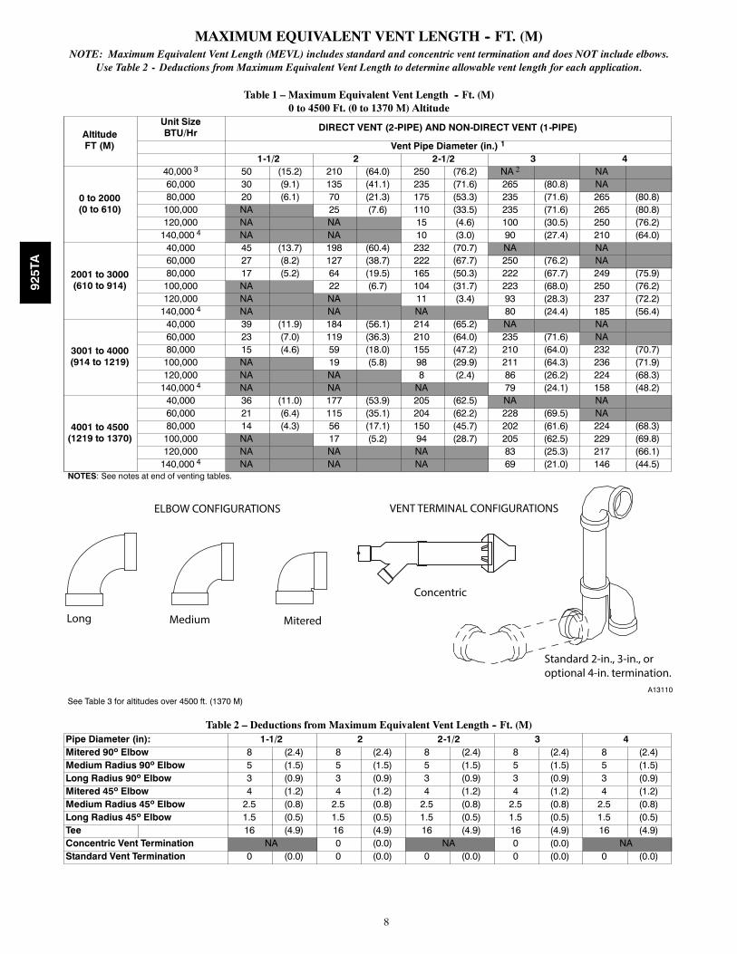
MAXIMUM EQUIVALENT VENT LENGTH -- FT. (M)NOTE: Maximum Equivalent Vent Length (MEVL) includes standard and concentric vent termination and does NOT include elbows.
Use Table 2 - Deductions from Maximum Equivalent Vent Length to determine allowable vent length for each application.
Table 1 – Maximum Equivalent Vent Length -- Ft. (M)0 to 4500 Ft. (0 to 1370 M) Altitude
AltitudeFT (M)
Unit SizeBTU/Hr DIRECT VENT (2-PIPE) AND NON-DIRECT VENT (1-PIPE)
Vent Pipe Diameter (in.) 1
1-1/2 2 2-1/2 3 4
0 to 2000(0 to 610)
40,000 3 50 (15.2) 210 (64.0) 250 (76.2) NA 2 NA60,000 30 (9.1) 135 (41.1) 235 (71.6) 265 (80.8) NA80,000 20 (6.1) 70 (21.3) 175 (53.3) 235 (71.6) 265 (80.8)100,000 NA 25 (7.6) 110 (33.5) 235 (71.6) 265 (80.8)120,000 NA NA 15 (4.6) 100 (30.5) 250 (76.2)140,000 4 NA NA 10 (3.0) 90 (27.4) 210 (64.0)
2001 to 3000(610 to 914)
40,000 45 (13.7) 198 (60.4) 232 (70.7) NA NA60,000 27 (8.2) 127 (38.7) 222 (67.7) 250 (76.2) NA80,000 17 (5.2) 64 (19.5) 165 (50.3) 222 (67.7) 249 (75.9)100,000 NA 22 (6.7) 104 (31.7) 223 (68.0) 250 (76.2)120,000 NA NA 11 (3.4) 93 (28.3) 237 (72.2)140,000 4 NA NA NA 80 (24.4) 185 (56.4)
3001 to 4000(914 to 1219)
40,000 39 (11.9) 184 (56.1) 214 (65.2) NA NA60,000 23 (7.0) 119 (36.3) 210 (64.0) 235 (71.6) NA80,000 15 (4.6) 59 (18.0) 155 (47.2) 210 (64.0) 232 (70.7)100,000 NA 19 (5.8) 98 (29.9) 211 (64.3) 236 (71.9)120,000 NA NA 8 (2.4) 86 (26.2) 224 (68.3)140,000 4 NA NA NA 79 (24.1) 158 (48.2)
4001 to 4500(1219 to 1370)
40,000 36 (11.0) 177 (53.9) 205 (62.5) NA NA60,000 21 (6.4) 115 (35.1) 204 (62.2) 228 (69.5) NA80,000 14 (4.3) 56 (17.1) 150 (45.7) 202 (61.6) 224 (68.3)100,000 NA 17 (5.2) 94 (28.7) 205 (62.5) 229 (69.8)120,000 NA NA NA 83 (25.3) 217 (66.1)140,000 4 NA NA NA 69 (21.0) 146 (44.5)
NOTES: See notes at end of venting tables.
Long Medium Mitered
Concentric
Standard 2-in., 3-in., or optional 4-in. termination.
ELBOW CONFIGURATIONS VENT TERMINAL CONFIGURATIONS
A13110
See Table 3 for altitudes over 4500 ft. (1370 M)
Table 2 – Deductions from Maximum Equivalent Vent Length -- Ft. (M)Pipe Diameter (in): 1-1/2 2 2-1/2 3 4Mitered 90º Elbow 8 (2.4) 8 (2.4) 8 (2.4) 8 (2.4) 8 (2.4)Medium Radius 90º Elbow 5 (1.5) 5 (1.5) 5 (1.5) 5 (1.5) 5 (1.5)Long Radius 90º Elbow 3 (0.9) 3 (0.9) 3 (0.9) 3 (0.9) 3 (0.9)Mitered 45º Elbow 4 (1.2) 4 (1.2) 4 (1.2) 4 (1.2) 4 (1.2)Medium Radius 45º Elbow 2.5 (0.8) 2.5 (0.8) 2.5 (0.8) 2.5 (0.8) 2.5 (0.8)Long Radius 45º Elbow 1.5 (0.5) 1.5 (0.5) 1.5 (0.5) 1.5 (0.5) 1.5 (0.5)Tee 16 (4.9) 16 (4.9) 16 (4.9) 16 (4.9) 16 (4.9)Concentric Vent Termination NA 0 (0.0) NA 0 (0.0) NAStandard Vent Termination 0 (0.0) 0 (0.0) 0 (0.0) 0 (0.0) 0 (0.0)
925TA
9
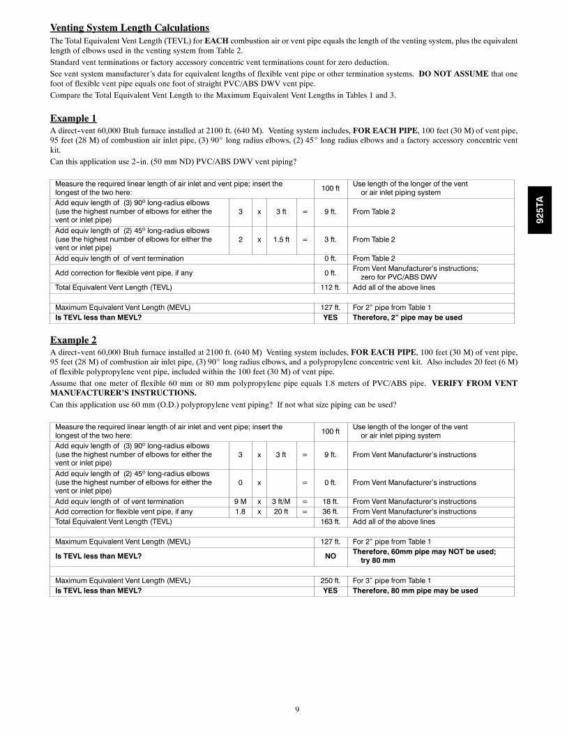
Venting System Length CalculationsThe Total Equivalent Vent Length (TEVL) for EACH combustion air or vent pipe equals the length of the venting system, plus the equivalentlength of elbows used in the venting system from Table 2.
Standard vent terminations or factory accessory concentric vent terminations count for zero deduction.
See vent system manufacturer’s data for equivalent lengths of flexible vent pipe or other termination systems. DO NOT ASSUME that onefoot of flexible vent pipe equals one foot of straight PVC/ABS DWV vent pipe.
Compare the Total Equivalent Vent Length to the Maximum Equivalent Vent Lengths in Tables 1 and 3.
Example 1A direct--vent 60,000 Btuh furnace installed at 2100 ft. (640 M). Venting system includes, FOR EACH PIPE, 100 feet (30 M) of vent pipe,95 feet (28 M) of combustion air inlet pipe, (3) 90_ long radius elbows, (2) 45_ long radius elbows and a factory accessory concentric ventkit.
Can this application use 2--in. (50 mm ND) PVC/ABS DWV vent piping?
Measure the required linear length of air inlet and vent pipe; insert thelongest of the two here: 100 ft Use length of the longer of the vent
or air inlet piping systemAdd equiv length of (3) 90º long-radius elbows(use the highest number of elbows for either thevent or inlet pipe)
3 x 3 ft = 9 ft. From Table 2
Add equiv length of (2) 45º long-radius elbows(use the highest number of elbows for either thevent or inlet pipe)
2 x 1.5 ft = 3 ft. From Table 2
Add equiv length of of vent termination 0 ft. From Table 2
Add correction for flexible vent pipe, if any 0 ft. From Vent Manufacturer’s instructions;zero for PVC/ABS DWV
Total Equivalent Vent Length (TEVL) 112 ft. Add all of the above lines
Maximum Equivalent Vent Length (MEVL) 127 ft. For 2” pipe from Table 1Is TEVL less than MEVL? YES Therefore, 2” pipe may be used
Example 2A direct--vent 60,000 Btuh furnace installed at 2100 ft. (640 M) Venting system includes, FOR EACH PIPE, 100 feet (30 M) of vent pipe,95 feet (28 M) of combustion air inlet pipe, (3) 90_ long radius elbows, and a polypropylene concentric vent kit. Also includes 20 feet (6 M)of flexible polypropylene vent pipe, included within the 100 feet (30 M) of vent pipe.
Assume that one meter of flexible 60 mm or 80 mm polypropylene pipe equals 1.8 meters of PVC/ABS pipe. VERIFY FROM VENTMANUFACTURER’S INSTRUCTIONS.Can this application use 60 mm (O.D.) polypropylene vent piping? If not what size piping can be used?
Measure the required linear length of air inlet and vent pipe; insert thelongest of the two here: 100 ft Use length of the longer of the vent
or air inlet piping systemAdd equiv length of (3) 90º long-radius elbows(use the highest number of elbows for either thevent or inlet pipe)
3 x 3 ft = 9 ft. From Vent Manufacturer’s instructions
Add equiv length of (2) 45º long-radius elbows(use the highest number of elbows for either thevent or inlet pipe)
0 x = 0 ft. From Vent Manufacturer’s instructions
Add equiv length of of vent termination 9 M x 3 ft/M = 18 ft. From Vent Manufacturer’s instructionsAdd correction for flexible vent pipe, if any 1.8 x 20 ft = 36 ft. From Vent Manufacturer’s instructionsTotal Equivalent Vent Length (TEVL) 163 ft. Add all of the above lines
Maximum Equivalent Vent Length (MEVL) 127 ft. For 2” pipe from Table 1
Is TEVL less than MEVL? NO Therefore, 60mm pipe may NOT be used;try 80 mm
Maximum Equivalent Vent Length (MEVL) 250 ft. For 3” pipe from Table 1Is TEVL less than MEVL? YES Therefore, 80 mm pipe may be used
925TA
10
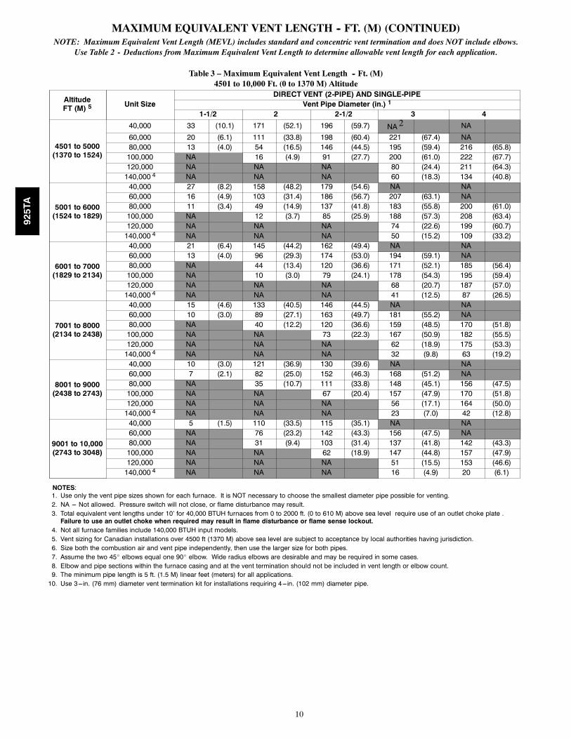
MAXIMUM EQUIVALENT VENT LENGTH -- FT. (M) (CONTINUED)NOTE: Maximum Equivalent Vent Length (MEVL) includes standard and concentric vent termination and does NOT include elbows.
Use Table 2 - Deductions from Maximum Equivalent Vent Length to determine allowable vent length for each application.
Table 3 – Maximum Equivalent Vent Length -- Ft. (M)4501 to 10,000 Ft. (0 to 1370 M) Altitude
AltitudeFT (M) 5 Unit Size
DIRECT VENT (2-PIPE) AND SINGLE-PIPEVent Pipe Diameter (in.) 1
1-1/2 2 2-1/2 3 4
4501 to 5000(1370 to 1524)
40,000 33 (10.1) 171 (52.1) 196 (59.7) NA 2 NA60,000 20 (6.1) 111 (33.8) 198 (60.4) 221 (67.4) NA80,000 13 (4.0) 54 (16.5) 146 (44.5) 195 (59.4) 216 (65.8)100,000 NA 16 (4.9) 91 (27.7) 200 (61.0) 222 (67.7)120,000 NA NA NA 80 (24.4) 211 (64.3)140,000 4 NA NA NA 60 (18.3) 134 (40.8)
5001 to 6000(1524 to 1829)
40,000 27 (8.2) 158 (48.2) 179 (54.6) NA NA60,000 16 (4.9) 103 (31.4) 186 (56.7) 207 (63.1) NA80,000 11 (3.4) 49 (14.9) 137 (41.8) 183 (55.8) 200 (61.0)100,000 NA 12 (3.7) 85 (25.9) 188 (57.3) 208 (63.4)120,000 NA NA NA 74 (22.6) 199 (60.7)140,000 4 NA NA NA 50 (15.2) 109 (33.2)
6001 to 7000(1829 to 2134)
40,000 21 (6.4) 145 (44.2) 162 (49.4) NA NA60,000 13 (4.0) 96 (29.3) 174 (53.0) 194 (59.1) NA80,000 NA 44 (13.4) 120 (36.6) 171 (52.1) 185 (56.4)100,000 NA 10 (3.0) 79 (24.1) 178 (54.3) 195 (59.4)120,000 NA NA NA 68 (20.7) 187 (57.0)140,000 4 NA NA NA 41 (12.5) 87 (26.5)
7001 to 8000(2134 to 2438)
40,000 15 (4.6) 133 (40.5) 146 (44.5) NA NA60,000 10 (3.0) 89 (27.1) 163 (49.7) 181 (55.2) NA80,000 NA 40 (12.2) 120 (36.6) 159 (48.5) 170 (51.8)100,000 NA NA 73 (22.3) 167 (50.9) 182 (55.5)120,000 NA NA NA 62 (18.9) 175 (53.3)140,000 4 NA NA NA 32 (9.8) 63 (19.2)
8001 to 9000(2438 to 2743)
40,000 10 (3.0) 121 (36.9) 130 (39.6) NA NA60,000 7 (2.1) 82 (25.0) 152 (46.3) 168 (51.2) NA80,000 NA 35 (10.7) 111 (33.8) 148 (45.1) 156 (47.5)100,000 NA NA 67 (20.4) 157 (47.9) 170 (51.8)120,000 NA NA NA 56 (17.1) 164 (50.0)140,000 4 NA NA NA 23 (7.0) 42 (12.8)
9001 to 10,000(2743 to 3048)
40,000 5 (1.5) 110 (33.5) 115 (35.1) NA NA60,000 NA 76 (23.2) 142 (43.3) 156 (47.5) NA80,000 NA 31 (9.4) 103 (31.4) 137 (41.8) 142 (43.3)100,000 NA NA 62 (18.9) 147 (44.8) 157 (47.9)120,000 NA NA NA 51 (15.5) 153 (46.6)140,000 4 NA NA NA 16 (4.9) 20 (6.1)
NOTES:1. Use only the vent pipe sizes shown for each furnace. It is NOT necessary to choose the smallest diameter pipe possible for venting.2. NA --- Not allowed. Pressure switch will not close, or flame disturbance may result.3. Total equivalent vent lengths under 10’ for 40,000 BTUH furnaces from 0 to 2000 ft. (0 to 610 M) above sea level require use of an outlet choke plate .Failure to use an outlet choke when required may result in flame disturbance or flame sense lockout.
4. Not all furnace families include 140,000 BTUH input models.5. Vent sizing for Canadian installations over 4500 ft (1370 M) above sea level are subject to acceptance by local authorities having jurisdiction.6. Size both the combustion air and vent pipe independently, then use the larger size for both pipes.7. Assume the two 45_ elbows equal one 90_ elbow. Wide radius elbows are desirable and may be required in some cases.8. Elbow and pipe sections within the furnace casing and at the vent termination should not be included in vent length or elbow count.9. The minimum pipe length is 5 ft. (1.5 M) linear feet (meters) for all applications.10. Use 3---in. (76 mm) diameter vent termination kit for installations requiring 4---in. (102 mm) diameter pipe.
925TA
11
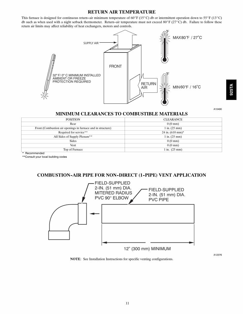
RETURN AIR TEMPERATUREThis furnace is designed for continuous return--air minimum temperature of 60_F (15_C) db or intermittent operation down to 55_F (13_C)db such as when used with a night setback thermometer. Return--air temperature must not exceed 80_F (27_C) db. Failure to follow thesereturn air limits may affect reliability of heat exchangers, motors and controls.
60
80 / 27˚C
/ 16˚C
SUPPLY AIR
A10490
MINIMUM CLEARANCES TO COMBUSTIBLE MATERIALSPOSITION CLEARANCE
Rear 0 (0 mm)Front (Combustion air openings in furnace and in structure) 1 in. (25 mm)
Required for service** 24 in. (610 mm)*All Sides of Supply Plenum** 1 in. (25 mm)
Sides 0 (0 mm)Vent 0 (0 mm)
Top of Furnace 1 in. (25 mm)* Recommended**Consult your local building codes
COMBUSTION--AIR PIPE FOR NON--DIRECT (1--PIPE) VENT APPLICATION
FIELD-SUPPLIED2-IN. (51 mm) DIA.PVC PIPE
FIELD-SUPPLIED2-IN. (51 mm) DIA.MITERED RADIUSPVC 90° ELBOW
12” (300 mm) MINIMUMA12376
NOTE: See Installation Instructions for specific venting configurations.
925TA
12
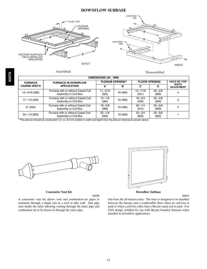
DOWNFLOW SUBBASELOCATING
TAB
LOCATINGTAB
1 2 3 4
4 3 2 1
B
D
C
A
1 1/4-IN. TYP
PLENUMOPENING
FACTORY-SUPPLIEDFIELD-INSTALLED
INSULATION
Assembled Disassembled
A97427 A88207
DIMENSIONS (IN. / MM)
FURNACECASING WIDTH
FURNACE IN DOWNFLOWAPPLICATION
PLENUM OPENING* FLOOR OPENING HOLE NO. FORWIDTH
ADJUSTMENTA B C D
14---3/16 (360) Furnace with or without Cased CoilAssembly or Coil Box
11---3/16(322) 19 (483) 13---7/16
(341)20---5/8(600) 4
17---1/2 (445) Furnace with or without Cased CoilAssembly or Coil Box
15---1/8(384) 19 (483) 16---3/4
(426)20---5/8(600) 3
21 (533) Furnace with or without Cased CoilAssembly or Coil Box
18---5/8(396) 19 (483) 20---1/4
(514)20---5/8(600) 2
24---1/2 (622) Furnace with or without Cased CoilAssembly or Coil Box
22---1/8(562) 19 (483) 23---3/4
(603)20---5/8(600) 1
*The plenum should be constructed 1/4---in. (6 mm) smaller in width and depth than the plenum dimensions shown above.
Concentric Vent KitA93086
A concentric vent kit allows vent and combustion--air pipes toterminate through a single exit in a roof or side wall. One piperuns inside the other allowing venting through the inner pipe andcombustion air to be drawn in through the outer pipe.
Downflow SubbaseA88202
One base fits all furnace sizes. The base is designed to be installedbetween the furnace and a combustible floor when no coil box isused or when a coil box other than a Bryant cased coil is used. It isCSA design certified for use with Bryant branded furnaces wheninstalled in downflow applications.
925TA
13
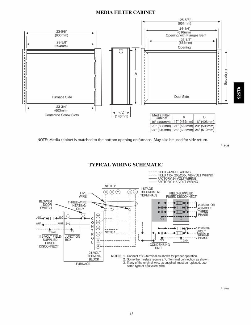
MEDIA FILTER CABINET
Media FilterCabinet A B
16" (406mm)20" (508mm)24" (610mm)
17" (432mm)
Furnace Side
Centerline Screw Slots
23-3/4”
23-3/8”
23-5/8"
534
Duct Side
Opening
Opening with Flanges Bent
24-1/4”
25-5/8"
B O
pening
A
"
(600mm)
(594mm)
(603mm)
(146mm)
(651mm)
(616mm)
23-1/8”(588mm)
16" (406mm)20" (508mm)24" (610mm)
21" (533mm)25" (635mm)
NOTE: Media cabinet is matched to the bottom opening on furnace. May also be used for side return.A12428
TYPICAL WIRING SCHEMATIC
115-VOLT FIELD-SUPPLIED
FUSEDDISCONNECT
JUNCTIONBOX
24-VOLTTERMINALBLOCK
THREE-WIREHEATING-
ONLY
FIVEWIRE
NOTE 2
NOTE 1
1-STAGETHERMOSTATTERMINALS
FIELD-SUPPLIEDFUSED DISCONNECT
CONDENSINGUNIT
FURNACE
COM
R
W C Y R G
GND
GND
FIELD 24-VOLT WIRINGFIELD 115-, 208/230-, 460-VOLT WIRINGFACTORY 24-VOLT WIRINGFACTORY 115-VOLT WIRING
Connect Y/Y2-terminal as shown for proper operation.Some thermostats require a "C" terminal connection as shown.If any of the original wire, as supplied, must be replaced, usesame type or equivalent wire.
208/230- OR460-VOLTTHREEPHASE
208/230-VOLTSINGLEPHASE
WHT
BLK
WHT
BLK
W/W1
W2
Y/Y2
G
NOTES: 1.2.3.
BLOWERDOOR
SWITCH
CONTROL
A11401
925TA
14
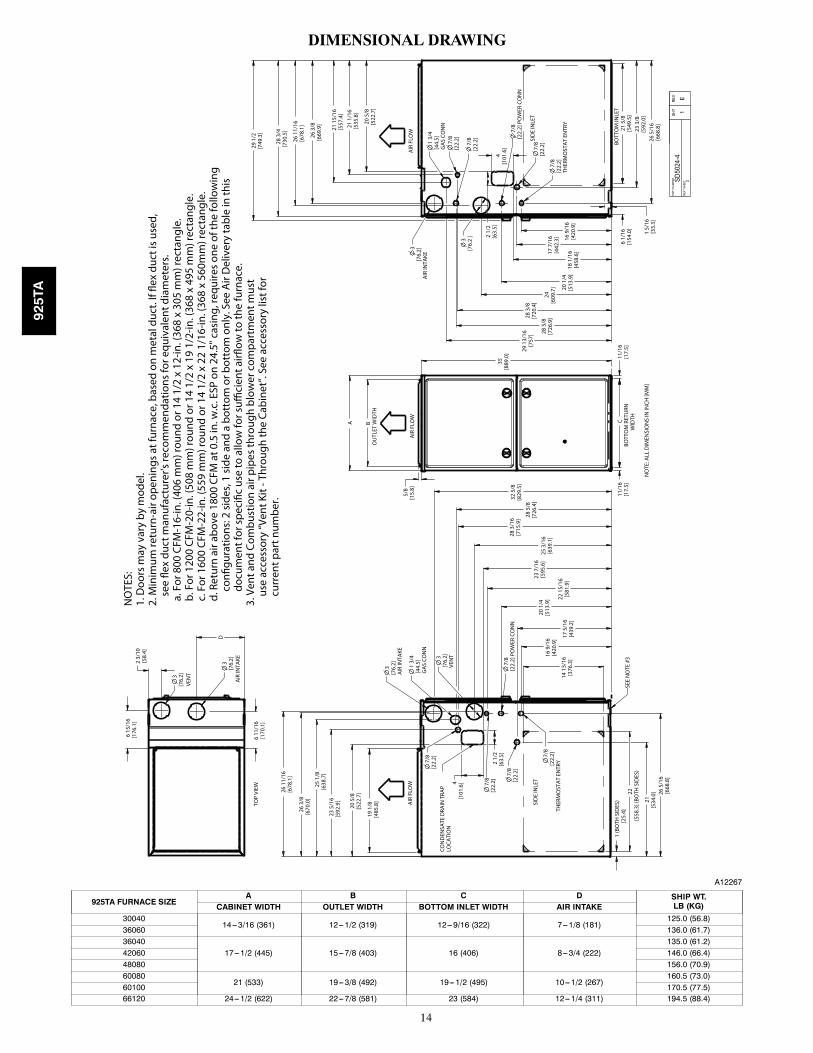
DIMENSIONAL DRAWING
6 15
/16
[176
.1]
3[7
6.2]
3[7
6.2]
6 11
/16
[170
.1]
23 5
/16
[592
.9]
25 1
/8[6
38.7
]
26 3
/8[6
70.0
]
26
11/1
6[6
78.1
]
21[5
34.0
] 26 5
/16
[668
.8]
17 5
/16
[439
.2]
16 9
/16
[420
.9]
20 1
/4[5
13.9
]25
3/1
6[6
39.1
]28 3
/16
[715
.9] 28
5/8
[726
.4]
32 5
/8[8
29.5
]
28 3
/4[7
30.5
]
26 3
/8[6
69.9
]
26 1
1/16
[678
.1]
21 1
5/16
[557
.4]
21 1
/16
[535
.8]
26 5
/16
[668
.8]
3[7
6.2]
AIR
INTA
KE
1 3/
4[4
4.5]
GA
S CO
NN
7/8
[22.
2]
7/8
[22.
2] P
OW
ER C
ON
N
7/8
[22.
2]
THER
MO
STA
T EN
TRY
7/8
[22.
2]
3[7
6.2]
AIR
INTA
KE1
3/4
[44.
5]G
AS
CON
N7/
8[2
2.2]
7/8
[22.
2]
3[7
6.2
]
7/8
[22.
2]
7/8
[22.
2]TH
ERM
OST
AT
ENTR
Y22
15/
16[5
81.9
]16
9/1
6[4
20.9
]
17 7
/16
[442
.3]
20 1
/4[5
13.9
]
24[6
09.7
]
28 3
/8[7
20.4
]
28 5
/8[7
26.9
]
29 1
3/16
[757
]
23 3
/8[5
92.0
]
3[7
6.2]
VEN
T
1 (B
OTH
SID
ES)
[25.
4]
D
2 3/
10[5
8.4]
CBO
TTO
M R
ETU
RNW
IDTH
11/1
6[1
7.5]
11/1
6[1
7.5]
BO
UTL
ET W
IDTH
A
22[5
58.3
] (BO
TH S
IDES
)
14 1
3/16
[376
.3]
35[8
89.0
]
5/8
[15.
8]
1 5/
16[3
3.3]
29 1
/2[7
49.3
]
19 1
/8[4
85.8
]
20 5
/8[5
22.7
]
23 7
/16
[595
.6]
[101
.6]4
[63.
5]2
1/2
18 1
/16
[458
.6]
2 1/
2[6
3.5]
4[1
01.6
]
20 5
/8[5
22.7
]
BOTT
OM
INLE
T 2
1 5/
8 [5
49.5
]
6 1/
16[1
54.0
]
PAR
T NU
MBE
R
S
D502
4-4
SH
T 1
RE
V E N
EXT
SHEE
T
2
VEN
T
AIR
INTA
KE
AIR
FLO
WA
IR F
LOW
SID
E IN
LET
SID
E IN
LET
CON
DEN
SATE
DRA
IN T
RAP
LOCA
TIO
N
NO
TE: A
LL D
IMEN
SIO
NS
IN IN
CH [M
M]
[22.
2]7/8
7/8
[22.
2] P
OW
ER C
ON
N
AIR
FLO
W
SEE
NO
TE #
3
NO
TES:
1. D
oors
may
var
y by
mod
el.
2. M
inim
um re
turn
-air
open
ings
at f
urna
ce, b
ased
on
met
al d
uct.
If fle
x du
ct is
use
d,
s
ee fl
ex d
uct m
anuf
actu
rer's
reco
mm
enda
tions
for e
quiv
alen
t dia
met
ers.
a. F
or 8
00 C
FM-1
6-in
. (40
6 m
m) r
ound
or 1
4 1/
2 x
12-in
. (36
8 x
305
mm
) rec
tang
le.
b. F
or 1
200
CFM
-20-
in. (
508
mm
) rou
nd o
r 14
1/2
x 19
1/2
-in. (
368
x 49
5 m
m) r
ecta
ngle
. c
. For
160
0 CF
M-2
2-in
. (55
9 m
m) r
ound
or 1
4 1/
2 x
22 1
/16-
in. (
368
x 56
0mm
) rec
tang
le.
d. R
etur
n ai
r abo
ve 1
800
CFM
at 0
.5 in
. w.c
. ESP
on
24.5
" cas
ing,
requ
ires
one
of th
e fo
llow
ing
confi
gura
tions
: 2 s
ides
, 1 s
ide
and
a bo
ttom
or b
otto
m o
nly.
See
Air
Del
iver
y ta
ble
in th
is
docu
men
t for
spe
cific
use
to a
llow
for s
uffici
ent a
irflow
to th
e fu
rnac
e.3.
Ven
t and
Com
bust
ion
air p
ipes
thro
ugh
blow
er c
ompa
rtm
ent m
ust
u
se a
cces
sory
“Ven
t Kit
- Thr
ough
the
Cabi
net”
. See
acc
esso
ry li
st fo
r
cur
rent
par
t num
ber.
TOP
VIEW
A12267
925TA FURNACE SIZEA B C D SHIP WT.
LB (KG)CABINET WIDTH OUTLET WIDTH BOTTOM INLET WIDTH AIR INTAKE30040
14---3/16 (361) 12---1/2 (319) 12---9/16 (322) 7---1/8 (181)125.0 (56.8)
36060 136.0 (61.7)36040
17---1/2 (445) 15---7/8 (403) 16 (406) 8---3/4 (222)135.0 (61.2)
42060 146.0 (66.4)48080 156.0 (70.9)60080
21 (533) 19---3/8 (492) 19---1/2 (495) 10---1/2 (267)160.5 (73.0)
60100 170.5 (77.5)66120 24---1/2 (622) 22---7/8 (581) 23 (584) 12---1/4 (311) 194.5 (88.4)
925TA
15
GUIDE SPECIFICATIONSGeneralSystem DescriptionFurnish a ______________________ 4--way multipoise gas--firedtwo--stage condensing furnace for use with natural gas or propane(factory-- authorized conversion kit required for propane); furnishexternal media cabinet for use with accessory media filter orstandard filter.
Quality AssuranceUnit will be designed, tested and constructed to the current ANSI Z21.47/CSA 2.3 design standard for gas--fired central furnaces.
Unit will be third party certified by CSA to the current ANSI Z21.47/CSA 2.3 design standard for gas--fired central furnaces. Unitwill carry the CSA Blue StarR and Blue FlameR labels. Unitefficiency testing will be performed per the current DOE testprocedure as listed in the Federal Register.
Unit will be certified for capacity and efficiency and listed in thelatest AHRI Consumer’s Directory of Certified Efficiency Ratings.
Unit will carry the current Federal Trade Commission EnergyGuide efficiency label.
Delivery, Storage, and HandlingUnit will be shipped as single package only and is stored andhandled per unit manufacturer’s recommendations.
Warranty (for inclusion by specifying engineer)U.S. and Canada only. Warranty certificate available upon request.
EquipmentBlower Wheel and ECM Blower Motor
Galvanized blower wheel shall be centrifugal type, statically anddynamically balanced. Blower motor of ECM type shall bepermanently lubricated with sealed ball bearings, of _______hp,and have multiple speeds from 600--1200 RPM operating onlywhen 24--VAC motor inputs are provided. Blower motor shall bedirect drive and soft mounted to the blower housing to reducevibration transmission.
Filters
Furnace shall have reusable--type filters. Filter shall be ______ in.(mm) X ________ in. (mm). An accessory highly efficient MediaFilter is available as an option. _____________ Media Filter.
Casing
Casing shall be of .030 in. thickness minimum, pre--painted steel.
Draft Inducer Motor
Draft inducer motor shall be two--speed PSC design.
Primary Heat Exchangers
Primary heat exchangers shall be 3--Pass corrosion--resistantaluminized steel of fold--and--crimp sectional design and appliedoperating under negative pressure.
Secondary Heat Exchangers
Secondary heat exchangers shall be of a stainless steelflow--through of fin--and--tube design and applied operating undernegative pressure.
Controls
Controls shall include a micro--processor--based integratedelectronic control board with at least 16 service troubleshootingcodes displayed via diagnostic flashing LED light on the control, aself--test feature that checks all major functions of the furnace, anda replaceable automotive--type circuit protection fuse. Multipleoperational settings available, including blower speeds for lowheat, high heat, low cooling, high cooling and continuous fan.Continuous fan speed may be adjusted from the thermostat.Features will also include temporary reduced airflow in the coolingmode for improved dehumidification when a T6--PRH is selectedas the thermostat.
Operating CharacteristicsHeating capacity shall be _________________ Btuh input;______________ Btuh output capacity.
Fuel Gas Efficiency shall be __________ AFUE.
Air delivery shall be ________________ cfm minimum at 0.50 in.W.C. external static pressure.
Dimensions shall be: depth_________in. (mm); width__________in. (mm); height___________in. (mm) (casing only).Height shall be _________in. (mm) with A/C coil and_________________in. (mm) overall with plenum.
Electrical RequirementsElectrical supply shall be 115 volts, 60 Hz, single--phase (nominal).Minimum wire size shall be ________AWG; maximum fuse sizeof HACR--type designated circuit breaker shall be _________amps.
Special FeaturesRefer to section of the product data identifying accessories anddescriptions for specific features and available enhancements.
925TA

16
Manufacturer reserves the right to discontinue, or change at any time, specifications or designs without notice and without incurring obligations.
E2013 Bryant Heating & Cooling Systems D 7310 W. Morris St. D Indianapolis, IN 46231 Edition Date: 09/13
Replaces: PDS925TA---05
Catalog No. PDS925TA---06
925TA