Embed Size (px)
Citation preview
58STA/STX4---WAY MULTIPOISE INDUCED---COMBUSTIONGAS FURNACEInput Capacities: 45,000 thru 155,000 BtuhSeries 160
Product Data
A10247
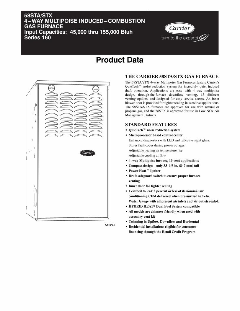
THE CARRIER 58STA/STX GAS FURNACEThe 58STA/STX 4--way Multipoise Gas Furnaces feature Carrier’sQuieTecht noise reduction system for incredibly quiet induceddraft operation. Applications are easy with 4--way multipoisedesign, through-the-furnace downflow venting, 13 differentventing options, and designed for easy service access. An innerblower door is provided for tighter sealing in sensitive applications.The 58STA/STX furnaces are approved for use with natural orpropane gas, and the 58STX is approved for use in Low NOx AirManagement Districts.
STANDARD FEATURESS QuieTecht noise reduction system
S Microprocessor based control center
Enhanced diagnostics with LED and reflective sight glass.
Stores fault codes during power outages.
Adjustable heating air temperature rise
Adjustable cooling airflow
S 4--way Multipoise furnace, 13 vent applications
S Compact design -- only 33--1/3 in. (847 mm) tall
S Power Heatt Igniter
S Draft safeguard switch to ensure proper furnace
venting
S Inner door for tighter sealing
S Certified to leak 2 percent or less of its nominal air
conditioning CFM delivered when pressurized to 1--In.
Water Gauge with all present air inlets and air outlets sealed.
S HYBRID HEATr Dual Fuel System compatible
S All models are chimney friendly when used with
accessory vent kitS Twinning in Upflow, Downflow and Horizontal
S Residential installations eligible for consumer
financing through the Retail Credit Program
2
MODEL NUMBER NOMENCLATURE
58STA 045 100 08
58STA 4--Way Multipoise Nominal Cooling Size58STX Low NOx version (Airflow at .5 e.s.p.)
(400 CFM per 12,000 Btuh)08---800 CFM12---1200 CFM14---1400 CFM16---1600 CFM
Input Capacity 20---2000 CFM045---44,000 Btuh 110---110,000 Btuh 22---2200 CFM070---66,000 Btuh 135---132,000 Btuh090---88,000 Btuh 155---154,000 Btuh Series Number
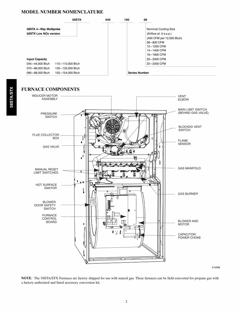
FURNACE COMPONENTSINDUCER MOTOR
ASSEMBLY
PRESSURESWITCH
FLUE COLLECTORBOX
GAS VALVE
HOT SURFACEIGNITOR
BLOWERDOOR SAFETY
SWITCH
FURNACECONTROL
BOARD
VENTELBOW
MAIN LIMIT SWITCH(BEHIND GAS VALVE)
BLOCKED VENTSWITCH
FLAMESENSOR
GAS MANIFOLD
GAS BURNER
BLOWER ANDMOTOR
MANUAL RESETLIMIT SWITCHES
CAPACITOR/POWER CHOKE
A10308
NOTE: The 58STA/STX Furnaces are factory shipped for use with natural gas. These furnaces can be field-converted for propane gas witha factory-authorized and listed accessory conversion kit.
58STA/STX
3
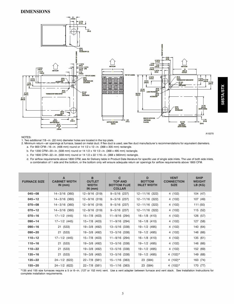
DIMENSIONS
AA
B
[736.9][736.9]2929
Ø7/8Ø7/8[22.2][22.2]
ACCESSORYACCESSORY
5 15/165 15/16[150.7][150.7]
28.3928.39[721.2][721.2]
Ø7/8Ø7/8[22.2][22.2]
ACCESSORYACCESSORY
14 7/814 7/8[337.3][337.3]
(BOTH SIDES)(BOTH SIDES)Ø7/8Ø7/8[22.2][22.2]ACCESSORYACCESSORY
Ø7/8Ø7/8[22.2][22.2]
ACCESSORYACCESSORY
Ø1 3/4Ø1 3/4[44.5][44.5]GAS ENTRYGAS ENTRY
Ø1/2Ø1/2[12.7][12.7]THERMOSTAT WIRE ENTRYTHERMOSTAT WIRE ENTRY
22 1/1622 1/16[560][560]
SIDE INLETSIDE INLET(BOTH SIDES)(BOTH SIDES)
11 7/1611 7/16[290.7][290.7]
9 11/169 11/16[245.4][245.4][197.8][197.8]
7 13/167 13/16
Ø7/8Ø7/8[22.2][22.2]
J.BOX PROVISIONJ.BOX PROVISION
Ø7/8Ø7/8[22.2][22.2]JUNCTION BOXJUNCTION BOXLOCATIONLOCATION
Ø1 3/4Ø1 3/4[44.5][44.5]GAS ENTRYGAS ENTRY
1 15/161 15/16[49.2][49.2]
1[25.4][25.4]
1 1/41 1/4[31.8][31.8]
29 9/1629 9/16[750.7][750.7]
1 15/161 15/16[49.2][49.2]
5 5/85 5/8[143.3][143.3]
5 7/165 7/16[138.5][138.5]
6 13/166 13/16[172.3][172.3]
Ø1/2Ø1/2[12.7][12.7]
THERMOSTAT WIRE ENTRYTHERMOSTAT WIRE ENTRY
1919[481.7][481.7]
OUTLETOUTLET
D21.621.6[549.5][549.5]
BOTTOM INLETBOTTOM INLET
C
33 1/433 1/4[843.9][843.9]
9 9/169 9/16[243.3][243.3]
3/43/4[19.1][19.1]
5 7/85 7/8[148.5][148.5]
3 7/163 7/16[86.8][86.8]
9 7/89 7/8[250.7][250.7]
27 3/427 3/4[704.7][704.7]
2 5/162 5/16[59][59]
FRO
NT
OF
CASI
NG
FRO
NT
OF
CASI
NG
TOP OF CASINGTOP OF CASING4 13/164 13/16[122.2][122.2]
27 3/427 3/4[704.7][704.7]
5 7/85 7/8[148.5][148.5]
8 5/88 5/8[219][219]
5 1/25 1/2[140.3][140.3]
8 7/168 7/16[213.5][213.5]
FRO
NT
OF
CASI
NG
FRO
NT
OF
CASI
NG
TOP OF CASINGTOP OF CASING
6.16.1[155.7][155.7]
2 1/162 1/16[51.6][51.6]
5.15.1[130.5][130.5]
1.71.7[43.5][43.5]
Ø7/8Ø7/8[22.2][22.2]ACCESSORY (2)ACCESSORY (2)
AIR FLOWAIR FLOW
AIR FLOWAIR FLOW
BOTTOM RETURNBOTTOM RETURNWIDTHWIDTH
AIR FLOWAIR FLOW
KNOCK OUTS FORKNOCK OUTS FORVENTING(5 VENTING(5 PLACES)PLACES)
A10270
NOTES:1. Two additional 7/8---in. (22 mm) diameter holes are located in the top plate.2. Minimum return ---air openings at furnace, based on metal duct. If flex duct is used, see flex duct manufacturer’s recommendations for equivalent diameters.a. For 800 CFM---16---in. (406 mm) round or 14 1/2 x 12---in. (368 x 305 mm) rectangle.b. For 1200 CFM---20---in. (508 mm) round or 14 1/2 x 19 1/2---in. (368 x 495 mm) rectangle.c. For 1600 CFM---22---in. (559 mm) round or 14 1/2 x 22 1/16---in. (368 x 560mm) rectangle.d. For airflow requirements above 1800 CFM, see Air Delivery table in Product Data literature for specific use of single side inlets. The use of both side inlets,a combination of 1 side and the bottom, or the bottom only will ensure adequate return air openings for airflow requirements above 1800 CFM.
FURNACE SIZEA
CABINET WIDTHIN (mm)
BOUTLETWIDTHIN (mm)
CTOP AND
BOTTOM FLUECOLLAR
DBOTTOM
INLET WIDTH
VENTCONNECTION
SIZE
SHIPWEIGHTLB (KG)
045---08 14---3/16 (360) 12---9/16 (319) 9---5/16 (237) 12---11/16 (322) 4 (102) 104 (47)
045---12 14---3/16 (360) 12---9/16 (319) 9---5/16 (237) 12---11/16 (322) 4 (102) 107 (49)
070---08 14---3/16 (360) 12---9/16 (319) 9---5/16 (237) 12---11/16 (322) 4 (102) 111 (50)
070---12 14---3/16 (360) 12---9/16 (319) 9---5/16 (237) 12---11/16 (322) 4 (102) 115 (52)
070---16 17---1/2 (445) 15---7/8 (403) 11---9/16 (294) 16---1/8 (410) 4 (102) 126 (57)
090---14 17---1/2 (445) 15---7/8 (403) 11---9/16 (294) 16---1/8 (410) 4 (102) 127 (58)
090---16 21 (533) 19---3/8 (492) 13---5/16 (338) 19---1/2 (495) 4 (102) 140 (64)
090---20 21 (533) 19---3/8 (492) 13---5/16 (338) 19---1/2 (495) 4 (102) 146 (66)
110---12 17---1/2 (445) 15---7/8 (403) 11---9/16 (294) 16---1/8 (410) 4 (102) 135 (61)
110---16 21 (533) 19---3/8 (492) 13---5/16 (338) 19---1/2 (495) 4 (102) 146 (66)
110---22 21 (533) 19---3/8 (492) 13---5/16 (338) 19---1/2 (495) 4 (102) 152 (69)
135---16 21 (533) 19---3/8 (492) 13---5/16 (338) 19---1/2 (495) 4 (102)* 149 (68)
135---22 24---1/2 (622) 22---7/8 (581) 15---1/16 (383) 23 (584) 4 (102)* 163 (74)
155---20 24---1/2 (622) 22---7/8 (581) 15---1/16 (383) 23 (584) 4 (102)* 170 (77)
*135 and 155 size furnaces require a 5 or 6---in. (127 or 152 mm) vent. Use a vent adapter between furnace and vent stack. See Installation Instructions forcomplete installation requirements.
58STA/STX
4
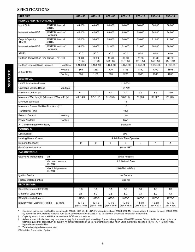
SPECIFICATIONS
UNIT SIZE 045--08 045--12 070--08 070--12 070--16 090--14 090--16
RATINGS AND PERFORMANCE
Input Btuh* 58STX Upflow; all58STA
44,000 44,000 66,000 66,000 66,000 88,000 88,000
Nonweatherized ICS 58STX Downflow/Horizontal
42,000 42,000 63,000 63,000 63,000 84,000 84,000
Output Capacity(Btuh)†
58STX Upflow; all58STA
35,000 36,000 53,000 54,000 53,000 71,000 71.000
Nonweatherized ICS 58STX Downflow/Horizontal
34,000 34,000 51,000 51,000 51,000 68,000 68,000
AFUE† 80.0 80.0 80.0 80.0 80.0 80.0 80.0
Certified Temperature Rise Range --- ° F (° C) 30-60(17---33)
20-50(11---28)
40-70(22---39)
30-60(17---33)
25-55(14---30)
40-70(22---39)
30-60(17---33)
Certified External Static Pressure Heat/Cool 0.10/0.50 0.10/0.50 0.12/0.50 0.12/0.50 0.12/0.50 0.15/0.50 0.15/0.50
Airflow CFM‡Heating 865 1250 720 1195 1350 1300 1505
Cooling 835 1160 870 1200 1505 1385 1635
ELECTRICAL
Unit Volts---Hertz---Phase 115-60-1
Operating Voltage Range Min-Max 104-127
Maximum Unit Amps 5.2 7.2 5.1 7.2 9.5 8.6 10.0
Maximum Wire Length (Measure 1 Way in Ft (M) 49 (14.9) 37 (11.2) 51 (15.5) 38 (11.5) 29 (8.8) 32 (9.7) 28 (8.5)
Minimum Wire Size 14
Maximum Fuse or Ckt Bkr Size (Amps)** 15
Transformer (24v) 40va
External Control Heating 12va
Power Available Cooling 35va
Air Conditioning Blower Relay Standard
CONTROLS
Limit Control SPST
Heating Blower Control Solid-State Time Operation
Burners (Monoport) 2 2 3 3 3 4 4
Gas Connection Size 1/2-in. NPT
GAS CONTROLS
Gas Valve (Redundant) Mfr. White-Rodgers
Min. inlet pressure(In. W.C.)
4.5 (Natural Gas)
Max. inlet pressure(In. W.C.)
13.6 (Natural Gas)
Ignition Device Hot Surface
Factory-installed orifice Size 43
BLOWER DATA
Direct-Drive Motor HP (PSC) 1/5 1/3 1/5 1/3 1/2 1/3 1/2
Motor Full Load Amps 2.8 5.2 2.8 5.2 7.1 5.2 7.1
RPM (Nominal)-Speeds 1075-3 1075-3 1075-3 1075-3 1075-3 1075-3 1075-3
Blower Wheel Diameter x Width --- In. (mm) 10 x 6(254 x 152)
10 x 6(254 x 152)
10 x 6(254 x 152)
10 x 6(254 x 152)
11 x 8(279 x 203)
10 x 8(254 x 203)
10 x 10(254 x 254)
* Gas input ratings are certified for elevations to 2000 ft. (610 M). In USA, For elevations above 2000 ft (610 M), reduce ratings 4 percent for each 1000 ft (305M) above sea level. Refer to National Fuel Gas Code NFPA 54/ANSI Z223.1---2012 Table F.4 or furnace installation instructions.
† Capacity in accordance with U.S. Government DOE test procedures.‡ Airflow shown is for bottom only return-air supply for the as-shipped speed tap. For air delivery above 1800 CFM, see Air Delivery table for other options. A
filter is required for each return-air supply. An airflow reduction of up to 7 percent may occur when using the factory-specified 4-5/16---in. (110 mm) wide,high efficiency media filter.
** Time---delay type is recommended.ICS Isolated Combustion System
58STA/STX
5
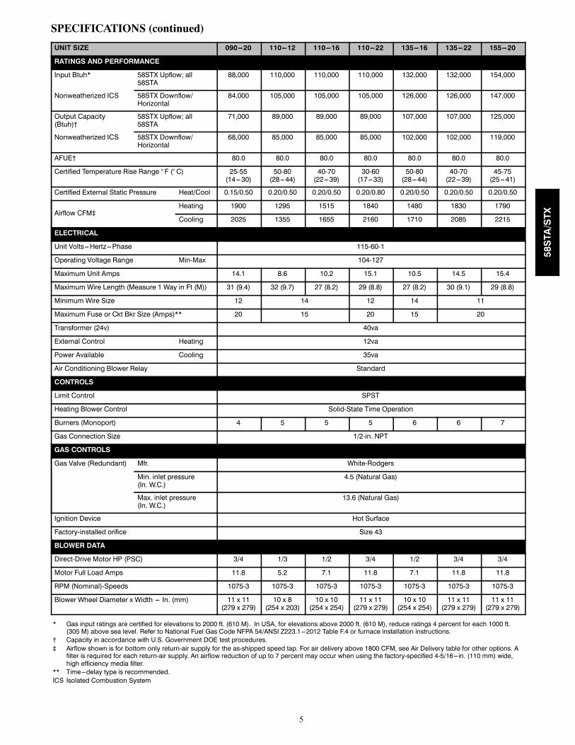
SPECIFICATIONS (continued)
UNIT SIZE 090--20 110--12 110--16 110--22 135--16 135--22 155--20
RATINGS AND PERFORMANCE
Input Btuh* 58STX Upflow; all58STA
88,000 110,000 110,000 110,000 132,000 132,000 154,000
Nonweatherized ICS 58STX Downflow/Horizontal
84,000 105,000 105,000 105,000 126,000 126,000 147,000
Output Capacity(Btuh)†
58STX Upflow; all58STA
71,000 89,000 89,000 89,000 107,000 107,000 125,000
Nonweatherized ICS 58STX Downflow/Horizontal
68,000 85,000 85,000 85,000 102,000 102,000 119,000
AFUE† 80.0 80.0 80.0 80.0 80.0 80.0 80.0
Certified Temperature Rise Range ° F (° C) 25-55(14---30)
50-80(28---44)
40-70(22---39)
30-60(17---33)
50-80(28---44)
40-70(22---39)
45-75(25---41)
Certified External Static Pressure Heat/Cool 0.15/0.50 0.20/0.50 0.20/0.50 0.20/0.80 0.20/0.50 0.20/0.50 0.20/0.50
Airflow CFM‡Heating 1900 1295 1515 1840 1480 1830 1790
Cooling 2025 1355 1655 2160 1710 2085 2215
ELECTRICAL
Unit Volts---Hertz---Phase 115-60-1
Operating Voltage Range Min-Max 104-127
Maximum Unit Amps 14.1 8.6 10.2 15.1 10.5 14.5 15.4
Maximum Wire Length (Measure 1 Way in Ft (M)) 31 (9.4) 32 (9.7) 27 (8.2) 29 (8.8) 27 (8.2) 30 (9.1) 29 (8.8)
Minimum Wire Size 12 14 12 14 11
Maximum Fuse or Ckt Bkr Size (Amps)** 20 15 20 15 20
Transformer (24v) 40va
External Control Heating 12va
Power Available Cooling 35va
Air Conditioning Blower Relay Standard
CONTROLS
Limit Control SPST
Heating Blower Control Solid-State Time Operation
Burners (Monoport) 4 5 5 5 6 6 7
Gas Connection Size 1/2-in. NPT
GAS CONTROLS
Gas Valve (Redundant) Mfr. White-Rodgers
Min. inlet pressure(In. W.C.)
4.5 (Natural Gas)
Max. inlet pressure(In. W.C.)
13.6 (Natural Gas)
Ignition Device Hot Surface
Factory-installed orifice Size 43
BLOWER DATA
Direct-Drive Motor HP (PSC) 3/4 1/3 1/2 3/4 1/2 3/4 3/4
Motor Full Load Amps 11.8 5.2 7.1 11.8 7.1 11.8 11.8
RPM (Nominal)-Speeds 1075-3 1075-3 1075-3 1075-3 1075-3 1075-3 1075-3
Blower Wheel Diameter x Width --- In. (mm) 11 x 11(279 x 279)
10 x 8(254 x 203)
10 x 10(254 x 254)
11 x 11(279 x 279)
10 x 10(254 x 254)
11 x 11(279 x 279)
11 x 11(279 x 279)
* Gas input ratings are certified for elevations to 2000 ft. (610 M). In USA, for elevations above 2000 ft. (610 M), reduce ratings 4 percent for each 1000 ft.(305 M) above sea level. Refer to National Fuel Gas Code NFPA 54/ANSI Z223.1---2012 Table F.4 or furnace installation instructions.
† Capacity in accordance with U.S. Government DOE test procedures.‡ Airflow shown is for bottom only return-air supply for the as-shipped speed tap. For air delivery above 1800 CFM, see Air Delivery table for other options. A
filter is required for each return-air supply. An airflow reduction of up to 7 percent may occur when using the factory-specified 4-5/16---in. (110 mm) wide,high efficiency media filter.
** Time---delay type is recommended.ICS Isolated Combustion System
58STA/STX
6
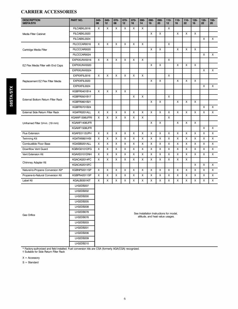
CARRIER ACCESSORIES
DESCRIPTION58STA/STX
PART NO. 045-08
045-12
070-08
070-12
070-16
090-14
090-16
090-20
110-12
110-16
110-22
135-16
135-22
155-20
Media Filter Cabinet
FILCABXL0016 X X X X X X X
FILCABXL0020 X X X X X
FILCABXL0024 X X
Cartridge Media Filter
FILCCCAR0016 X X X X X X X
FILCCCAR0020 X X X X X
FILCCCAR0024 X X
EZ Flex Media Filter with End Caps
EXPXXUNV0016 X X X X X X X
EXPXXUNV0020 X X X X X
EXPXXUNV0024 X X
Replacement EZ Flex Filter Media
EXPXXFIL0016 X X X X X X X
EXPXXFIL0020 X X X X X
EXPXXFIL0024 X X
External Bottom Return Filter Rack
KGBFR0401B14 X X X X
KGBFR0501B17 X X X
KGBFR0601B21 X X X X X
KGBFR0701B24 X X
External Side Return Filter Rack KGAFR0201ALL X X X X X X X X X X X X X X
Unframed Filter 3/4-in. (19 mm)
KGAWF1306UFR† X X X X X X X
KGAWF1406UFR X X X X X
KGAWF1506UFR X X
Flue Extension KGAFE0112UPH X X X X X X X X X X X X X X
Twinning Kit KGATW0601HSI X X X X X X X X X X X X X X
Combustible Floor Base KGASB0201ALL X X X X X X X X X X X X X X
Downflow Vent Guard KGBVG0101DFG X X X X X X X X X X X X X X
Vent Extension Kit KGAVE0101DNH X X X X X X X X X X X X X X
Chimney Adapter KitKGACA02014FC X X X X X X X X X X X
KGACA02015FC X X X
Natural-to-Propane Conversion Kit* KGBNP50011SP X X X X X X X X X X X X X X
Propane-to-Natural Conversion Kit KGBPN42011SP X X X X X X X X X X X X X X
Label Kit KGALB0301KIT X X X X X X X X X X X X X X
Gas Orifice
LH32DB207
See Installation Instructions for model,altitude, and heat value usages.
LH32DB202
LH32DB200
LH32DB205
LH32DB208
LH32DB078
LH32DB076
LH32DB203
LH32DB201
LH32DB206
LH32DB209
LH32DB210
* Factory-authorized and field installed. Fuel conversion kits are CSA (formerly AGA/CGA) recognized.† Suitable for Side Return Filter Rack
X = Accessory
S = Standard
58STA/STX
7
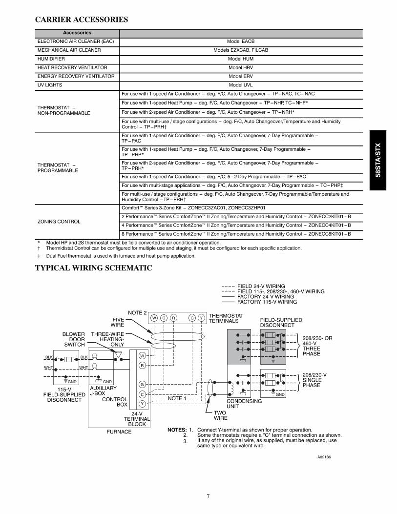
CARRIER ACCESSORIES
Accessories
ELECTRONIC AIR CLEANER (EAC) Model EACB
MECHANICAL AIR CLEANER Models EZXCAB, FILCAB
HUMIDIFIER Model HUM
HEAT RECOVERY VENTILATOR Model HRV
ENERGY RECOVERY VENTILATOR Model ERV
UV LIGHTS Model UVL
THERMOSTAT ---NON-PROGRAMMABLE
For use with 1-speed Air Conditioner --- deg. F/C, Auto Changeover --- TP---NAC, TC---NAC
For use with 1-speed Heat Pump --- deg. F/C, Auto Changeover --- TP---NHP, TC---NHP*
For use with 2-speed Air Conditioner --- deg. F/C, Auto Changeover --- TP---NRH*
For use with multi-use / stage configurations --- deg. F/C, Auto Changeover/Temperature and HumidityControl --- TP---PRH{
THERMOSTAT ---PROGRAMMABLE
For use with 1-speed Air Conditioner --- deg. F/C, Auto Changeover, 7-Day Programmable ---TP---PAC
For use with 1-speed Heat Pump --- deg. F/C, Auto Changeover, 7-Day Programmable ---TP---PHP*
For use with 2-speed Air Conditioner --- deg. F/C, Auto Changeover, 7-Day Programmable ---TP---PRH*
For use with 1-speed Air Conditioner --- deg. F/C, 5---2 Day Programmable --- TP---PAC
For use with multi-stage applications --- deg. F/C, Auto Changeover, 7-Day Programmable --- TC---PHP}
For multi-use / stage configurations --- deg. F/C, Auto Changeover, 7-Day Programmable/Temperature andHumidity Control ---TP---PRH{
ZONING CONTROL
Comfort™ Series 3-Zone Kit --- ZONECC3ZAC01, ZONECC3ZHP01
2 Performance™ Series ComfortZone™ II Zoning/Temperature and Humidity Control --- ZONECC2KIT01---B
4 Performance™ Series ComfortZone™ II Zoning/Temperature and Humidity Control --- ZONECC4KIT01---B
8 Performance™ Series ComfortZone™ II Zoning/Temperature and Humidity Control --- ZONECC8KIT01---B
* Model HP and 2S thermostat must be field converted to air conditioner operation.† Thermidistat Control can be configured for multiple use and staging, it must be configured for each specific application.
} Dual Fuel thermostat is used with furnace and heat pump application.
TYPICAL WIRING SCHEMATIC
A02186
58STA/STX
8
A02058
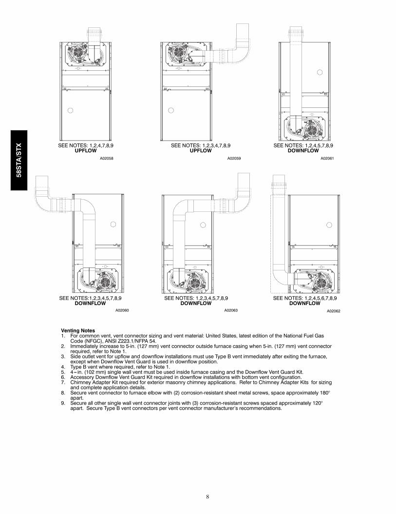
SEE NOTES: 1,2,4,7,8,9UPFLOW
SEE NOTES: 1,2,3,4,7,8,9UPFLOW
SEE NOTES: 1,2,4,5,7,8,9DOWNFLOW
A02059 A02061
SEE NOTES:1,2,3,4,5,7,8,9DOWNFLOW
SEE NOTES: 1,2,3,4,5,7,8,9DOWNFLOW
SEE NOTES: 1,2,4,5,6,7,8,9DOWNFLOW
A02060 A02063 A02062
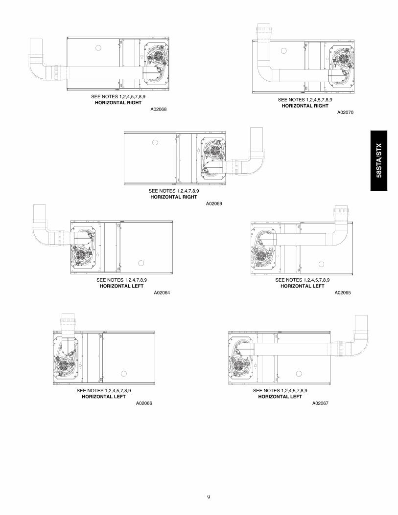
Venting Notes1. For common vent, vent connector sizing and vent material: United States, latest edition of the National Fuel GasCode (NFGC), ANSI Z223.1/NFPA 54.
2. Immediately increase to 5-in. (127 mm) vent connector outside furnace casing when 5-in. (127 mm) vent connectorrequired, refer to Note 1.
3. Side outlet vent for upflow and downflow installations must use Type B vent immediately after exiting the furnace,except when Downflow Vent Guard is used in downflow position.
4. Type B vent where required, refer to Note 1.5. 4--- in. (102 mm) single wall vent must be used inside furnace casing and the Downflow Vent Guard Kit.6. Accessory Downflow Vent Guard Kit required in downflow installations with bottom vent configuration.7. Chimney Adapter Kit required for exterior masonry chimney applications. Refer to Chimney Adapter Kits for sizingand complete application details.
8. Secure vent connector to furnace elbow with (2) corrosion-resistant sheet metal screws, space approximately 180°apart.
9. Secure all other single wall vent connector joints with (3) corrosion-resistant screws spaced approximately 120°apart. Secure Type B vent connectors per vent connector manufacturer’s recommendations.
58STA/STX
9
HORIZONTAL RIGHTSEE NOTES 1,2,4,5,7,8,9
A02068
HORIZONTAL RIGHTSEE NOTES 1,2,4,7,8,9
A02069
HORIZONTAL RIGHTSEE NOTES 1,2,4,5,7,8,9
A02070
HORIZONTAL LEFTSEE NOTES 1,2,4,7,8,9
A02064HORIZONTAL LEFT
SEE NOTES 1,2,4,5,7,8,9
A02065
HORIZONTAL LEFTSEE NOTES 1,2,4,5,7,8,9
A02066HORIZONTAL LEFT
SEE NOTES 1,2,4,5,7,8,9
A02067
58STA/STX

10
AIR DELIVERY -- CFM (With Filter)
FURNACESIZE
RETURN---AIRINLET SPEED EXTERNAL STATIC PRESSURE (In. W.C.)
0.1 0.2 0.3 0.4 0.5 0.6 0.7 0.8 0.9 1.0
045---08 Bottom orSide(s)
HighMed---HighMed---Low
1035865760
995830720
945790680
895745635
835690580
770625520
675545445
565440345
390250220
195195195
045---12 Bottom orSide(s)
HighMed---HighMed---Low
144013601250
137513001210
130512401160
124011751100
116011151040
10701040965
975950885
870850790
730725670
560575520
070---08 Bottom orSide(s)
HighMed---HighMed---Low
1030835725
1005815700
965790675
925755635
870710595
810660545
740590460
645480350
465325250
280205--- ---
070---12 Bottom orSide(s)
HighMed---HighMed---Low
142513201200
137512801175
132012401145
126512051105
120011401050
11251075990
1035995920
940905840
830790725
655620555
070---16 Bottom orSide(s)
HighMed---HighMed---Low
175515501355
170015201340
163514751310
157014301280
150513751240
143513101190
135012401125
126011551060
11601070975
1055970890
090---14 Bottom orSide(s)
HighMed---HighMed---Low
160514701310
157014451295
153514101265
146513801230
138513001195
128512201120
117511151025
1055990915
895830710
645600565
090---16 Bottom orSide(s)
HighMed---HighMed---Low
194017401505
188017001505
180516501480
172015901440
163515251375
154014401300
142513351190
129011951045
10901010890
830820740
090---20
Bottom OnlyHigh
Med---HighMed---Low
240521701920
231021101875
222020401835
213019701780
202518951715
192017851630
179016751535
166015651420
153014201275
135012601135
Both Sides or 1Side & Bottom
HighMed---HighMed---Low
253022301895
245021701890
236521101845
227020501815
216519851755
206518901685
194017801600
180516601480
167015251350
150513601180
1Side OnlyHigh
Med---HighMed---Low
247521051850
239521451860
230020701810
220020101770
209019401715
198518451650
186517351555
173016201445
158514751310
142513251150
110---12 Bottom orSide(s)
HighMed---HighMed---Low
160014751315
155014351295
149013951265
142513351220
135512851155
126011851080
11351070985
990890810
785725675
530450440
110---16 Bottom orSide(s)
HighMed---HighMed---Low
198017451530
191517101515
183516501470
175015601400
165514501310
149513401215
136512051095
11851090990
965865830
700605670
110---22
Bottom OnlyHigh
Med---HighMed---Low
248521351855
241521001840
234020601815
225520001775
216019301725
208018601675
195017651600
184016701510
172015551405
156514251290
Bottom Sidesor 1 Side & Bot-
tom
HighMed---HighMed---Low
--- ---21401855
--- ---21001840
235520501815
228519901775
219019351725
209018651675
196517601600
185016701510
170515451405
153514101290
1Side OnlyHigh
Med---HighMed---Low
24952030--- ---
244020251735
237020001725
229019501695
220519051650
212018501595
201517501535
191016601455
177515551335
162514251230
* A filter is required for each return ---air inlet. Airflow performance included 3/4---in. (19 mm) washable filter media such as contained in factory---authorized ac-cessory filter rack. To determine airflow performance without this filter, assume an additional 0.1 In. W.C. available external static pressure.
--- --- Indicates unstable operating conditions.
58STA/STX
11
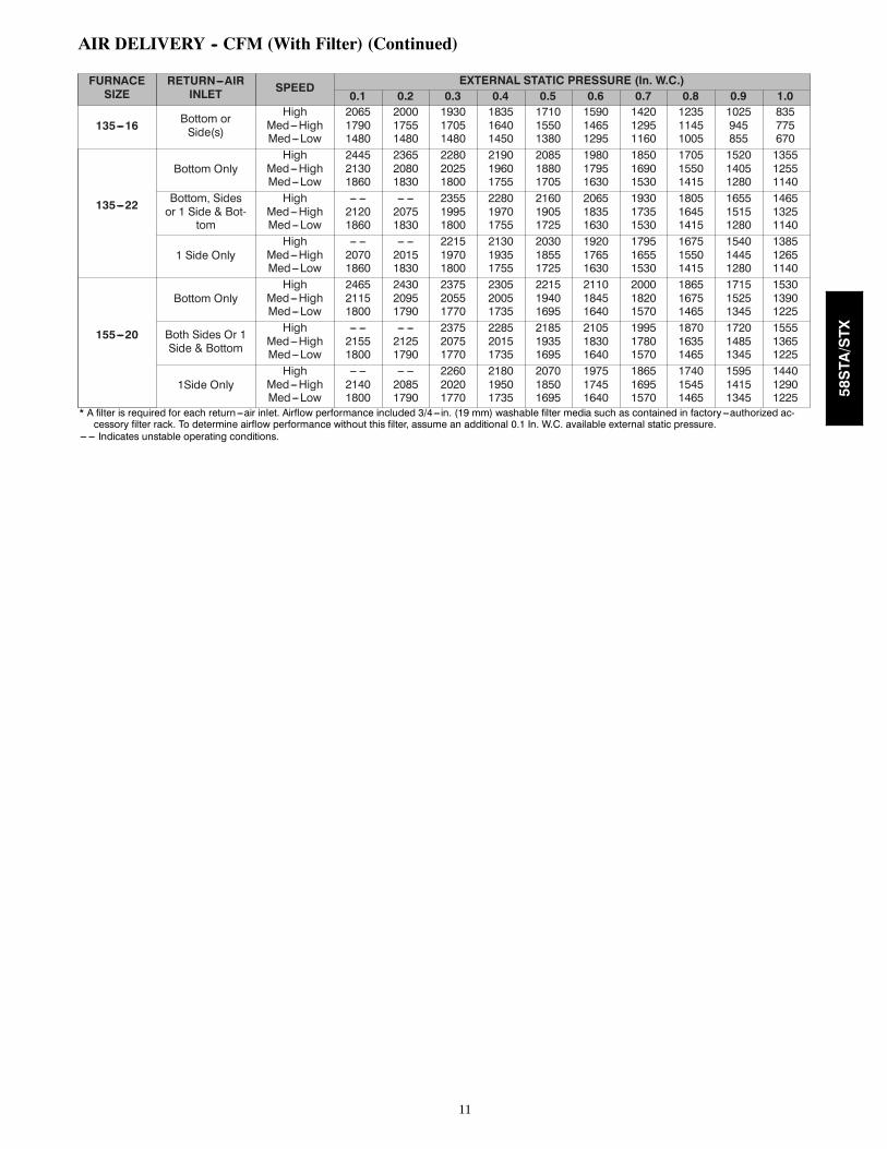
AIR DELIVERY -- CFM (With Filter) (Continued)
FURNACESIZE
RETURN---AIRINLET SPEED EXTERNAL STATIC PRESSURE (In. W.C.)
0.1 0.2 0.3 0.4 0.5 0.6 0.7 0.8 0.9 1.0
135---16 Bottom orSide(s)
HighMed---HighMed---Low
206517901480
200017551480
193017051480
183516401450
171015501380
159014651295
142012951160
123511451005
1025945855
835775670
135---22
Bottom OnlyHigh
Med---HighMed---Low
244521301860
236520801830
228020251800
219019601755
208518801705
198017951630
185016901530
170515501415
152014051280
135512551140
Bottom, Sidesor 1 Side & Bot-
tom
HighMed---HighMed---Low
--- ---21201860
--- ---20751830
235519951800
228019701755
216019051725
206518351630
193017351530
180516451415
165515151280
146513251140
1 Side OnlyHigh
Med---HighMed---Low
--- ---20701860
--- ---20151830
221519701800
213019351755
203018551725
192017651630
179516551530
167515501415
154014451280
138512651140
155---20
Bottom OnlyHigh
Med---HighMed---Low
246521151800
243020951790
237520551770
230520051735
221519401695
211018451640
200018201570
186516751465
171515251345
153013901225
Both Sides Or 1Side & Bottom
HighMed---HighMed---Low
--- ---21551800
--- ---21251790
237520751770
228520151735
218519351695
210518301640
199517801570
187016351465
172014851345
155513651225
1Side OnlyHigh
Med---HighMed---Low
--- ---21401800
--- ---20851790
226020201770
218019501735
207018501695
197517451640
186516951570
174015451465
159514151345
144012901225
* A filter is required for each return ---air inlet. Airflow performance included 3/4---in. (19 mm) washable filter media such as contained in factory---authorized ac-cessory filter rack. To determine airflow performance without this filter, assume an additional 0.1 In. W.C. available external static pressure.
--- --- Indicates unstable operating conditions.
58STA/STX
12
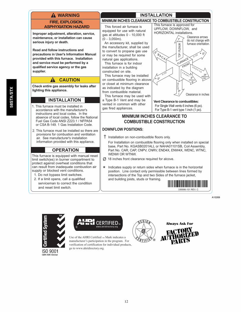
A10269
Always Ask For
Use of the AHRI Certified TM Mark indicates amanufacturer’s participation in the program. Forverification of certification for individual products,go to www.ahridirectory.org.
58STA/STX
13
GUIDE SPECIFICATIONSGas Furnace58STA/STXGeneralSYSTEM DESCRIPTION
Furnish a _________________ fixed capacity gas--firedfurnace for use with natural gas or propane (factoryauthorized conversion kit required for propane); furnishcold air return plenum.QUALITY ASSURANCE
Unit will be designed, tested and constructed to thecurrent ANSI Z 21.47/CSA 2.3 design standard forgas--fired central furnaces.
Unit will be 3rd party certified by CSA to the currentANSI Z 21.47/CSA 2.3 design standard for gas--firedcentral furnaces.
Unit will carry the CSA Blue StarR label.Unit efficiency testing will be performed per the current
DOE test procedure as listed in the Federal Register.Unit will be certified for capacity and efficiency and
listed in the latest AHRI Consumer’s Directory ofCertified Efficiency Ratings.
Unit shall carry the current Federal Trade CommissionEnergy Guide efficiency label.DELIVERY, STORAGE AND HANDLING
Unit shall be shipped as single package only and isstored and handled per unit manufacturer’srecommendations.WARRANTY (for inclusion by specifying engineer)
Warranty certificate available upon request.ProductsEQUIPMENT
Components shall include: slow--opening gas valve toreduce ignition noise, regulate gas flow, with electricswitch gas shut--off; flame proving sensor, hot surfaceigniter, pressure switch assembly, flame rollout switch,blower and inducer assembly, 40va transformer;low--voltage (heating) (heating/cooling) thermostat.Blower Wheel and Blower Motor
Galvanized blower wheel shall be centrifugal type,statically and dynamically balanced. Blower motor of PSCtype shall be permanently lubricated with sealed bearings,of _______hp, and shall be multiple--speed direct drive.Blower motor shall be soft mounted to the blower scroll toreduce vibration transmission.Filters
Furnace may have reusable--type filters. Filter shall be_______ in. (mm) (x) _______in. (mm). An accessoryhigh efficiency Media Filter is available as an option._______________ Media Filter.
Casing
Casing shall be of .030 in. (.76) thickness minimum,pre--painted steel.Inducer Motor
Inducer motor shall be soft mounted to reduce vibrationtransmission.Draft Safeguard Switch
Draft Safeguard Switch (blocked vent safeguard) shallbe factory installed to reduce the possibility of vent gasinfiltration due to a blocked or restricted vent pipe.Heat Exchangers
Heat exchangers shall be a 4-Pass 20 gage aluminizedsteel of fold--and--crimp sectional design when appliedoperating under negative pressure.Controls
Control shall include a micro--processor basedintegrated electronic control board with at least 11 servicetroubleshooting codes displayed via enhanced flashingLED diagnostic light on the control, a self--test feature thatchecks all major functions of the furnace within oneminute, and a non--volatile memory replaceableautomotive--type circuit protection fuse. Multipleoperational settings available including, separate blowerspeeds for heating, cooling and continuous fan.Continuous fan speed may be adjusted from thethermostat. Cooling airflow will be selectable between 350or 400 CFM per ton of air conditioning.OPERATING CHARACTERISTICS
Heating Capacity shall be ________ Btuh input;________ Btuh output capacity.
Fuel Gas Efficiency shall be 80% AFUE. Air deliveryshall be ___________ CFM minimum at 0.50 In. W.C.external static pressure.
Dimensions shall be: depth __________ in. (mm);width _________ in. (mm); height_________in. (mm)(casing only). Height shall be_________in. (mm) withA/C coil and _____________in. (mm) overall withplenum.ELECTRICAL REQUIREMENTS
Electrical supply shall be 115 volts, 60 Hz,single--phase (nominal). Minimum wire size shallbe_________AWG; maximum fuse size or circuit breakershall be __________Amps.SPECIAL FEATURES
Refer to section of the product data sheet identifyingaccessories and descriptions for specific features andavailable enhancements.
58STA/STX

14
Copyright 2013 Carrier Corp. D 7310 W. Morris St. D Indianapolis, IN 46231 . Edition Date: 08/13
Manufacturer reserves the right to change, at any time, specifications and designs without notice and without obligations.
Catalog No: 58ST---11PD
Replaces: 58ST---10PD
58STA/STX