Embed Size (px)
Citation preview
Copyright 2009 Carrier Corporation Form 30XA-5PD
AquaForce chillers were designed from the ground up to meet the effi-ciency demands of today and thefuture by providing premium air-cooled chiller packages for contrac-tors, consulting engineers andbuilding owners.• Rotary screw compression• R-134a HFC refrigerant• Quiet AeroAcoustic™ fan system• Novation® heat exchanger
technology with microchannel coil• Easy to use ComfortLink™ controls• Optional integrated hydronic
package
Features/BenefitsAquaForce 30XA chillers provide best full load and part load performance in a single chassis from 80 to500 tonsPremium performanceAqua series chillers are Carrier’s most efficient air-cooled models. The AquaForce chiller is one of the most affordable air-cooled chillers to oper-ate and maintain. The AquaForce chiller offers full load EER (Energy Efficiency Ratio) up to 10.9 and IPLV (Integrated Part-Load Value) up to 15.4 with Novation heat exchanger technol-ogy. High-efficiency rotary screw com-pressors with infinitely variable slide valves allow the chillers to exactly match actual load conditions, delivering exceptional part load performance. The AquaForce chillers deliver superior efficiency through the entire operating range to keep costs and demand charges down. This exceptional perfor-mance has a significant impact on energy savings and cost of ownership.
AQUAFORCE®
30XA080-500Air-Cooled Liquid Chillers
80 to 500 Nominal Tons(265 to 1615 Nominal kW)
ProductData
®
Well exceeds ASHRAE 90.1 Standards.
a30-4024
2
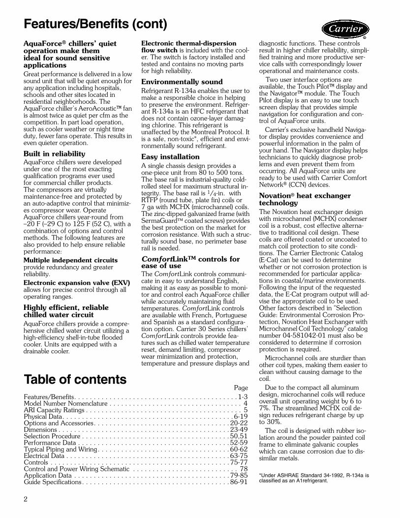
AquaForce® chillers’ quiet operation make themideal for sound sensitiveapplicationsGreat performance is delivered in a low sound unit that will be quiet enough for any application including hospitals, schools and other sites located in residential neighborhoods. The AquaForce chiller’s AeroAcoustic™ fan is almost twice as quiet per cfm as the competition. In part load operation, such as cooler weather or night time duty, fewer fans operate. This results in even quieter operation.
Built in reliabilityAquaForce chillers were developed under one of the most exactingqualification programs ever usedfor commercial chiller products.The compressors are virtuallymaintenance-free and protected byan auto-adaptive control that minimiz-es compressor wear. Operate AquaForce chillers year-round from–20 F (–29 C) to 125 F (52 C), with a combination of options and control methods. The following features are also provided to help ensure reliable performance:Multiple independent circuits provide redundancy and greaterreliability.Electronic expansion valve (EXV) allows for precise control through all operating ranges.
Highly efficient, reliable chilled water circuitAquaForce chillers provide a compre-hensive chilled water circuit utilizing a high-efficiency shell-in-tube flooded cooler. Units are equipped with a drainable cooler.
Electronic thermal-dispersion flow switch is included with the cool-er. The switch is factory installed and tested and contains no moving parts for high reliability.
Environmentally soundRefrigerant R-134a enables the user to make a responsible choice in helping to preserve the environment. Refriger-ant R-134a is an HFC refrigerant that does not contain ozone-layer damag-ing chlorine. This refrigerant isunaffected by the Montreal Protocol. It is a safe, non-toxic*, efficient and envi-ronmentally sound refrigerant.
Easy installationA single chassis design provides a one-piece unit from 80 to 500 tons. The base rail is industrial-quality cold-rolled steel for maximum structural in-tegrity. The base rail is 1/4-in. with RTFP (round tube, plate fin) coils or 7 ga with MCHX (microchannel) coils. The zinc-dipped galvanized frame (with SermaGuard™ coated screws) provides the best protection on the market for corrosion resistance. With such a struc-turally sound base, no perimeter base rail is needed.
ComfortLinkTM controls for ease of useThe ComfortLink controls communi-cate in easy to understand English, making it as easy as possible to moni-tor and control each AquaForce chiller while accurately maintaining fluid temperatures. ComfortLink controls are available with French, Portuguese and Spanish as a standard configura-tion option. Carrier 30 Series chillers’ ComfortLink controls provide fea-tures such as chilled water temperature reset, demand limiting, compressor wear minimization and protection, temperature and pressure displays and
diagnostic functions. These controls result in higher chiller reliability, simpli-fied training and more productive ser-vice calls with correspondingly lower operational and maintenance costs.
Two user interface options are available, the Touch Pilot™ display and the Navigator™ module. The TouchPilot display is an easy to use touch screen display that provides simple navigation for configuration and con-trol of AquaForce units. Carrier's exclusive handheld Naviga-tor display provides convenience and powerful information in the palm of your hand. The Navigator display helps technicians to quickly diagnose prob-lems and even prevent them from occurring. All AquaForce units are ready to be used with Carrier Comfort Network® (CCN) devices.
Novation® heat exchanger technologyThe Novation heat exchanger design with microchannel (MCHX) condenser coil is a robust, cost effective alterna-tive to traditional coil design. These coils are offered coated or uncoated to match coil protection to site condi-tions. The Carrier Electronic Catalog (E-Cat) can be used to determine whether or not corrosion protection is recommended for particular applica-tions in coastal/marine environments. Following the input of the requested data, the E-Cat program output will ad-vise the appropriate coil to be used. Other factors described in "Selection Guide: Environmental Corrosion Pro-tection, Novation Heat Exchanger with Microchannel Coil Technology" catalog number 04-581042-01 must also be considered to determine if corrosion protection is required. Microchannel coils are sturdier than other coil types, making them easier to clean without causing damage to the coil. Due to the compact all aluminumdesign, microchannel coils will reduce overall unit operating weight by 6 to 7%. The streamlined MCHX coil de-sign reduces refrigerant charge by up to 30%. The coil is designed with rubber iso-lation around the powder painted coil frame to eliminate galvanic couples which can cause corrosion due to dis-similar metals.
*Under ASHRAE Standard 34-1992, R-134a isclassified as an A1refrigerant.
Features/Benefits (cont)
Table of contentsPage
Features/Benefits. . . . . . . . . . . . . . . . . . . . . . . . . . . . . . . . . . . . . . . . . .1-3Model Number Nomenclature . . . . . . . . . . . . . . . . . . . . . . . . . . . . . . . . . . 4ARI Capacity Ratings . . . . . . . . . . . . . . . . . . . . . . . . . . . . . . . . . . . . . . . . 5Physical Data. . . . . . . . . . . . . . . . . . . . . . . . . . . . . . . . . . . . . . . . . . . .6-19Options and Accessories. . . . . . . . . . . . . . . . . . . . . . . . . . . . . . . . . . . 20-22Dimensions . . . . . . . . . . . . . . . . . . . . . . . . . . . . . . . . . . . . . . . . . . . . 23-49Selection Procedure . . . . . . . . . . . . . . . . . . . . . . . . . . . . . . . . . . . . . . 50,51Performance Data . . . . . . . . . . . . . . . . . . . . . . . . . . . . . . . . . . . . . . . 52-59Typical Piping and Wiring. . . . . . . . . . . . . . . . . . . . . . . . . . . . . . . . . . 60-62Electrical Data . . . . . . . . . . . . . . . . . . . . . . . . . . . . . . . . . . . . . . . . . . 63-75Controls . . . . . . . . . . . . . . . . . . . . . . . . . . . . . . . . . . . . . . . . . . . . . . 75-77Control and Power Wiring Schematic . . . . . . . . . . . . . . . . . . . . . . . . . . . 78Application Data . . . . . . . . . . . . . . . . . . . . . . . . . . . . . . . . . . . . . . . . 79-85Guide Specifications. . . . . . . . . . . . . . . . . . . . . . . . . . . . . . . . . . . . . . 86-91
3
PROPELLER FANAEROACOUSTIC FAN
1/3 OCTAVE BAND CENTER FREQUENCY (Hz)
SO
UN
D P
OW
ER
[dB
(A)]
AEROACOUSTIC™ FAN vs. PROPELLER FAN
PENETRATES BUILDINGSTRUCTURE
25 40 63 130 168 250 400 630 1080 1600 2400 4000 6300 8000
90
85
80
75
70
65
60
55
50
TUBES
FINS
MICROCHANNELS
MANIFOLD
Run StatusService TestTemperaturesPressures
SetpointsInputs
OutputsConfigurationTime Clock
Operating ModesAlarms
ENTER
ESC
MODEAlarm Status
ComfortLink
OPTIONAL NAVIGATOR™ DISPLAY
AEROACOUSTIC FAN VS PROPELLER FAN
SMOOTH ROTARY COMPRESSOR TWIN-SCREW DESIGN
OPTIONAL PUMP PACKAGE
TOUCH PILOT™ DISPLAY
NOVATION® HEAT EXCHANGER TECHNOLOGYWITH MICROCHANNEL CONDENSER COILS
a30-4456
30-562
a30-3924
a30-3162
a30-4458
a30-3926
a30-4457
LOW-NOISE AEROACOUSTIC FAN
4
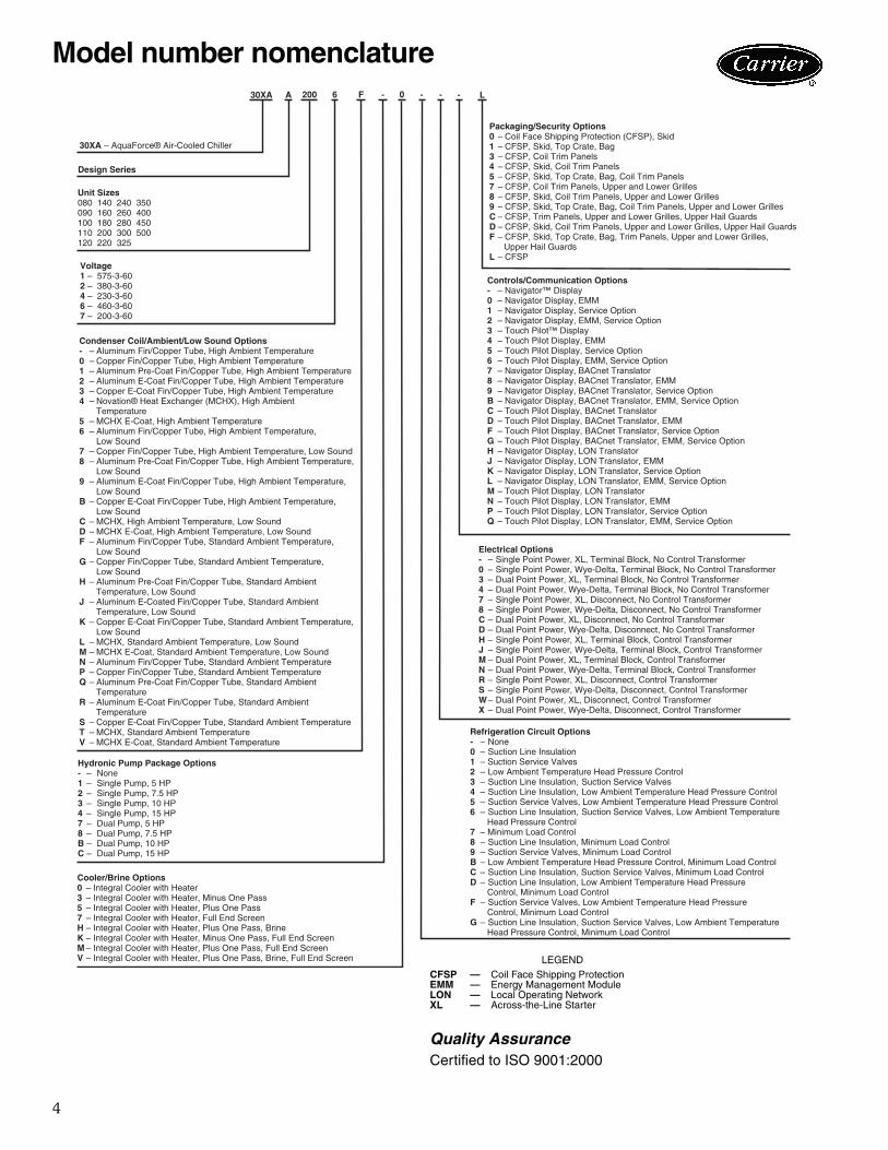
Model number nomenclature
30XA – AquaForce® Air-Cooled Chiller
Design Series
Unit Sizes 080 140 240 350 090 160 260 400 100 180 280 450 110 200 300 500 120 220 325
Voltage 1 – 575-3-602 – 380-3-604 – 230-3-606 – 460-3-607 – 200-3-60
Condenser Coil/Ambient/Low Sound Options- – Aluminum Fin/Copper Tube, High Ambient Temperature0 – Copper Fin/Copper Tube, High Ambient Temperature1 – Aluminum Pre-Coat Fin/Copper Tube, High Ambient Temperature2 – Aluminum E-Coat Fin/Copper Tube, High Ambient Temperature3 – Copper E-Coat Fin/Copper Tube, High Ambient Temperature4 – Novation® Heat Exchanger (MCHX), High Ambient Temperature5 – MCHX E-Coat, High Ambient Temperature6 – Aluminum Fin/Copper Tube, High Ambient Temperature, Low Sound7 – Copper Fin/Copper Tube, High Ambient Temperature, Low Sound8 – Aluminum Pre-Coat Fin/Copper Tube, High Ambient Temperature, Low Sound9 – Aluminum E-Coat Fin/Copper Tube, High Ambient Temperature, Low SoundB – Copper E-Coat Fin/Copper Tube, High Ambient Temperature, Low SoundC – MCHX, High Ambient Temperature, Low SoundD – MCHX E-Coat, High Ambient Temperature, Low SoundF – Aluminum Fin/Copper Tube, Standard Ambient Temperature, Low SoundG – Copper Fin/Copper Tube, Standard Ambient Temperature, Low SoundH – Aluminum Pre-Coat Fin/Copper Tube, Standard Ambient Temperature, Low SoundJ – Aluminum E-Coated Fin/Copper Tube, Standard Ambient Temperature, Low SoundK – Copper E-Coat Fin/Copper Tube, Standard Ambient Temperature, Low SoundL – MCHX, Standard Ambient Temperature, Low SoundM – MCHX E-Coat, Standard Ambient Temperature, Low SoundN – Aluminum Fin/Copper Tube, Standard Ambient TemperatureP – Copper Fin/Copper Tube, Standard Ambient TemperatureQ – Aluminum Pre-Coat Fin/Copper Tube, Standard Ambient TemperatureR – Aluminum E-Coat Fin/Copper Tube, Standard Ambient TemperatureS – Copper E-Coat Fin/Copper Tube, Standard Ambient TemperatureT – MCHX, Standard Ambient TemperatureV – MCHX E-Coat, Standard Ambient Temperature
Cooler/Brine Options0 – Integral Cooler with Heater3 – Integral Cooler with Heater, Minus One Pass5 – Integral Cooler with Heater, Plus One Pass7 – Integral Cooler with Heater, Full End ScreenH – Integral Cooler with Heater, Plus One Pass, BrineK – Integral Cooler with Heater, Minus One Pass, Full End ScreenM – Integral Cooler with Heater, Plus One Pass, Full End ScreenV – Integral Cooler with Heater, Plus One Pass, Brine, Full End Screen
Packaging/Security Options0 – Coil Face Shipping Protection (CFSP), Skid1 – CFSP, Skid, Top Crate, Bag3 – CFSP, Coil Trim Panels4 – CFSP, Skid, Coil Trim Panels5 – CFSP, Skid, Top Crate, Bag, Coil Trim Panels7 – CFSP, Coil Trim Panels, Upper and Lower Grilles8 – CFSP, Skid, Coil Trim Panels, Upper and Lower Grilles9 – CFSP, Skid, Top Crate, Bag, Coil Trim Panels, Upper and Lower GrillesC – CFSP, Trim Panels, Upper and Lower Grilles, Upper Hail GuardsD – CFSP, Skid, Coil Trim Panels, Upper and Lower Grilles, Upper Hail GuardsF – CFSP, Skid, Top Crate, Bag, Trim Panels, Upper and Lower Grilles, Upper Hail GuardsL – CFSP
Controls/Communication Options- – Navigator™ Display0 – Navigator Display, EMM1 – Navigator Display, Service Option2 – Navigator Display, EMM, Service Option3 – Touch Pilot™ Display4 – Touch Pilot Display, EMM5 – Touch Pilot Display, Service Option6 – Touch Pilot Display, EMM, Service Option7 – Navigator Display, BACnet Translator8 – Navigator Display, BACnet Translator, EMM9 – Navigator Display, BACnet Translator, Service OptionB – Navigator Display, BACnet Translator, EMM, Service OptionC – Touch Pilot Display, BACnet TranslatorD – Touch Pilot Display, BACnet Translator, EMMF – Touch Pilot Display, BACnet Translator, Service OptionG – Touch Pilot Display, BACnet Translator, EMM, Service OptionH – Navigator Display, LON TranslatorJ – Navigator Display, LON Translator, EMMK – Navigator Display, LON Translator, Service OptionL – Navigator Display, LON Translator, EMM, Service OptionM – Touch Pilot Display, LON TranslatorN – Touch Pilot Display, LON Translator, EMMP – Touch Pilot Display, LON Translator, Service OptionQ – Touch Pilot Display, LON Translator, EMM, Service Option
Electrical Options- – Single Point Power, XL, Terminal Block, No Control Transformer0 – Single Point Power, Wye-Delta, Terminal Block, No Control Transformer3 – Dual Point Power, XL, Terminal Block, No Control Transformer 4 – Dual Point Power, Wye-Delta, Terminal Block, No Control Transformer 7 – Single Point Power, XL, Disconnect, No Control Transformer 8 – Single Point Power, Wye-Delta, Disconnect, No Control TransformerC – Dual Point Power, XL, Disconnect, No Control TransformerD – Dual Point Power, Wye-Delta, Disconnect, No Control TransformerH – Single Point Power, XL, Terminal Block, Control TransformerJ – Single Point Power, Wye-Delta, Terminal Block, Control TransformerM – Dual Point Power, XL, Terminal Block, Control TransformerN – Dual Point Power, Wye-Delta, Terminal Block, Control TransformerR – Single Point Power, XL, Disconnect, Control TransformerS – Single Point Power, Wye-Delta, Disconnect, Control TransformerW – Dual Point Power, XL, Disconnect, Control TransformerX – Dual Point Power, Wye-Delta, Disconnect, Control Transformer
Refrigeration Circuit Options- – None0 – Suction Line Insulation1 – Suction Service Valves2 – Low Ambient Temperature Head Pressure Control3 – Suction Line Insulation, Suction Service Valves4 – Suction Line Insulation, Low Ambient Temperature Head Pressure Control5 – Suction Service Valves, Low Ambient Temperature Head Pressure Control6 – Suction Line Insulation, Suction Service Valves, Low Ambient Temperature Head Pressure Control7 – Minimum Load Control8 – Suction Line Insulation, Minimum Load Control9 – Suction Service Valves, Minimum Load ControlB – Low Ambient Temperature Head Pressure Control, Minimum Load ControlC – Suction Line Insulation, Suction Service Valves, Minimum Load ControlD – Suction Line Insulation, Low Ambient Temperature Head Pressure Control, Minimum Load ControlF – Suction Service Valves, Low Ambient Temperature Head Pressure Control, Minimum Load ControlG – Suction Line Insulation, Suction Service Valves, Low Ambient Temperature Head Pressure Control, Minimum Load Control
Hydronic Pump Package Options- – None1 – Single Pump, 5 HP2 – Single Pump, 7.5 HP3 – Single Pump, 10 HP4 – Single Pump, 15 HP7 – Dual Pump, 5 HP8 – Dual Pump, 7.5 HPB – Dual Pump, 10 HPC – Dual Pump, 15 HP
LEGEND
Quality AssuranceCertified to ISO 9001:2000
CFSP — Coil Face Shipping ProtectionEMM — Energy Management ModuleLON — Local Operating NetworkXL — Across-the-Line Starter
a30-4757
5
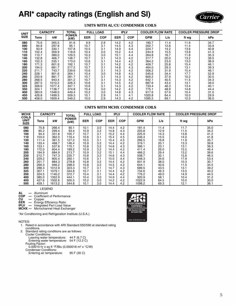
UNITS WITH AL/CU CONDENSER COILS
UNITS WITH MCHX CONDENSER COILS
LEGEND
*Air Conditioning and Refrigeration Institute (U.S.A.).
NOTES:1. Rated in accordance with ARI Standard 550/590 at standard rating
conditions.2. Standard rating conditions are as follows:
Cooler Conditions:Leaving water temperature: 44 F (6.7 C)Entering water temperature: 54 F (12.2 C)
Fouling Factor:0.00010 hr x sq ft °F/Btu (0.000018 m2 x °C/W)
Condenser Conditions:Entering air temperature: 95 F (35 C)
UNITSIZE
CAPACITY TOTALPOWER
(kW)
FULL LOAD IPLV COOLER FLOW RATE COOLER PRESSURE DROP
Tons kW EER COP EER COP GPM L/s ft wg kPa
080 75.6 265.5 91.6 9.9 2.9 14.2 4.2 180.7 11.4 11.6 34.7090 84.8 297.8 95.1 10.7 3.1 14.5 4.3 202.7 12.8 11.4 33.9100 93.9 330.1 107.8 10.5 3.1 14.9 4.4 224.7 14.2 13.6 40.8110 102.4 359.9 118.6 10.4 3.0 15.2 4.4 244.9 15.5 13.8 41.3120 110.7 389.0 129.5 10.3 3.0 15.1 4.4 264.8 16.7 11.8 35.3140 132.8 466.7 148.7 10.7 3.1 14.3 4.2 317.7 20.0 13.2 39.5160 152.3 535.1 173.0 10.6 3.1 14.4 4.2 364.2 23.0 13.0 38.9180 171.3 601.9 192.1 10.7 3.1 14.2 4.2 409.7 25.8 15.4 46.1200 194.0 681.7 217.2 10.7 3.1 14.8 4.3 464.0 29.3 13.1 39.3220 211.7 743.7 239.6 10.6 3.1 14.3 4.2 506.2 31.9 15.4 46.1240 228.1 801.6 264.1 10.4 3.0 14.8 4.3 545.6 34.4 17.7 52.9260 250.9 881.7 281.7 10.7 3.1 14.3 4.2 600.2 37.9 10.2 30.5280 268.5 943.4 301.2 10.7 3.1 14.3 4.2 642.1 40.5 11.5 34.3300 287.5 1010.2 326.3 10.6 3.1 14.5 4.2 687.6 43.4 13.1 39.0325 306.6 1077.4 347.1 10.6 3.1 14.3 4.2 733.4 46.3 13.4 40.1350 324.1 1138.7 374.8 10.4 3.0 14.2 4.2 775.1 48.9 14.8 44.4400 383.6 1348.0 449.4 10.2 3.0 14.8 4.3 917.6 57.9 10.4 31.0450 426.8 1499.5 509.3 10.1 2.9 14.1 4.1 1020.8 64.4 10.0 29.9500 458.0 1609.4 549.2 10.0 2.9 14.3 4.2 1095.5 69.1 12.0 36.0
MCHX COILSUNIT SIZE
CAPACITY TOTALPOWER
(kW)
FULL LOAD IPLV COOLER FLOW RATE COOLER PRESSURE DROP
Tons kW EER COP EER COP GPM L/s ft wg kPa
080 75.8 266.4 90.1 10.1 3.0 14.4 4.2 181.4 11.4 11.7 35.0090 85.2 299.4 93.4 10.9 3.2 14.8 4.3 203.8 12.9 11.5 34.2100 94.4 331.8 105.7 10.7 3.1 15.2 4.4 225.9 14.3 13.8 41.2110 103.0 362.0 116.4 10.6 3.1 15.4 4.5 246.4 15.5 14.0 41.8120 111.4 391.5 127.2 10.5 3.1 15.4 4.5 266.5 16.8 11.9 35.7140 133.4 468.7 146.4 10.9 3.2 14.4 4.2 319.1 20.1 13.3 39.8160 153.1 537.8 170.1 10.8 3.2 14.6 4.3 366.1 23.1 13.1 39.3180 172.0 604.4 189.2 10.9 3.2 14.4 4.2 411.4 26.0 15.5 46.4200 194.9 684.9 213.7 10.9 3.2 15.1 4.4 466.2 29.4 13.2 39.6220 212.7 747.3 235.7 10.8 3.2 14.6 4.3 508.7 32.1 15.6 46.5240 229.2 805.4 260.1 10.6 3.1 15.0 4.4 548.3 34.6 17.9 53.4260 251.7 884.3 278.8 10.8 3.2 14.4 4.2 601.9 38.0 10.3 30.7280 269.3 946.2 298.0 10.8 3.2 14.5 4.2 644.1 40.6 11.5 34.5300 288.3 1012.9 323.3 10.7 3.1 14.7 4.3 689.5 43.5 13.1 39.2325 307.1 1079.1 344.8 10.7 3.1 14.4 4.2 734.6 46.3 13.5 40.2350 324.5 1140.2 372.7 10.4 3.1 14.4 4.2 776.2 49.0 14.9 44.5400 385.0 1352.9 444.1 10.4 3.0 14.9 4.4 920.9 58.1 10.4 31.2450 427.6 1502.6 505.5 10.2 3.0 14.2 4.2 1022.9 64.5 10.0 30.0500 459.1 1613.2 544.8 10.1 3.0 14.4 4.2 1098.2 69.3 12.1 36.1
AL — AluminumCOP — Coefficient of PerformanceCU — CopperEER — Energy Efficiency RatioIPLV — Integrated Part Load ValueMCHX — Microchannel Heat Exchanger
ARI* capacity ratings (English and SI)
6
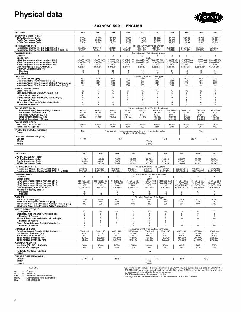
30XA080-500 — ENGLISH
LEGEND *Operating weight includes 2 pumps on models 30XA090-160. No pumps are available on 30XA080 or30XA180-500. All weights include coil trim panels. See pages 8-19 for mounting weights for units with-out pumps and units with single pump packages.
†30XA080 unit does not have an economizer.**The high ambient temperature option is not available on 30XA080-120 units.
UNIT 30XA 080 090 100 110 120 140 160 180 200 220
OPERATING WEIGHT (lb)*Al-Cu Condenser Coils 7,674 9,959 10,186 10,326 10,471 12,760 13,003 13,590 13,712 14,727Cu-Cu Condenser Coils 8,398 10,924 11,151 11,291 11,436 13,966 14,209 15,037 15,159 16,295MCHX Condenser Coils 7,234 9,382 9,603 9,738 9,877 12,023 12,255 12,699 12,810 13,748
REFRIGERANT TYPE R-134a, EXV Controlled SystemRefrigerant Charge (lb) Ckt A/Ckt B/Ckt C 110/110/— 110/110/— 120/120/— 135/120/— 135/135/— 202/121/— 225/159/— 205/205/— 225/225/— 270/225/—Refrigerant Charge (lb) Ckt A/Ckt B/Ckt C (MCHX) 98/98/— 94/94/— 96/96/— 100/96/— 100/100/— 136/96/— 135/100/— 141/141/— 161/161/— 170/161/—
COMPRESSORS Semi-Hermetic Twin Rotary ScrewsQuantity 2 2 2 2 2 2 2 2 2 2Speed (rpm) 3500(Qty) Compressor Model Number Ckt A (1) 06TS-137† (1) 06TS-137 (1) 06TS-155 (1) 06TS-186 (1) 06TS-186 (1) 06TT-266 (1) 06TT-301 (1) 06TT-266 (1) 06TT-301 (1) 06TT-356(Qty) Compressor Model Number Ckt B (1) 06TS-137† (1) 06TS-137 (1) 06TS-155 (1) 06TS-155 (1) 06TS-186 (1) 06TS-155 (1) 06TS-186 (1) 06TT-266 (1) 06TT-301 (1) 06TT-301(Qty) Compressor Model Number Ckt C N/A N/A N/A N/A N/A N/A N/A N/A N/A N/AOil Charge (gal), Ckt A/Ckt B/Ckt C 5.5/5.5/— 5.5/5.5/— 5.5/5.5/— 5.5/5.5/— 5.5/5.5/— 6.25/5.5/— 6.25/5.5/— 6.25/6.25/— 6.25/6.25/— 6.75/6.25/—Minimum Capacity Step (%)
Standard 15 15 15 14 15 11 11 15 15 14Optional 9 9 9 8 10 7 8 10 10 10
COOLER Flooded, Shell and Tube TypeNet Fluid Volume (gal.) 16.5 18.5 18.5 20.0 23.0 25.5 27.5 31.5 34.0 37.0Maximum Refrigerant Pressure (psig) 220 220 220 220 220 220 220 220 220 220Maximum Water Side Pressure Without Pumps (psig) 300 300 300 300 300 300 300 300 300 300Maximum Water Side Pressure With Pumps (psig) — 150 150 150 150 150 150 — — —
WATER CONNECTIONSDrain (NPT, in.) 3/8 3/8 3/8 3/8 3/8 3/8 3/8 3/8 3/8 3/8Standard, Inlet and Outlet, Victaulic (in.) 5 5 5 5 5 5 5 6 6 6
Number of Passes 2 2 2 2 2 2 2 2 2 2Minus 1 Pass, Inlet and Outlet, Victaulic (in.) 5 5 5 5 5 5 5 8 8 8
Number of Passes 1 1 1 1 1 1 1 1 1 1Plus 1 Pass, Inlet and Outlet, Victaulic (in.) 4 4 4 4 4 5 5 6 6 6
Number of Passes 3 3 3 3 3 3 3 3 3 3
CONDENSER FANS Shrouded Axial Type, Vertical DischargeFan Speed (rpm) Standard/High Ambient** 850/— 850/— 850/— 850/— 850/— 850/1140 850/1140 850/1140 850/1140 850/1140No. Blades...Diameter (in.) 9...30 9...30 9...30 9...30 9...30 9...30 9...30 9...30 9...30 9...30No. Fans (Ckt A/Ckt B/Ckt C) 3/3/— 4/4/— 4/4/— 4/4/— 4/4/— 6/4/— 6/4/— 6/6/— 6/6/— 7/6/—Total Airflow (cfm) 850 rpm 55,800 74,400 74,400 74,400 74,400 93,000 93,000 111,600 111,600 120,900Total Airflow (cfm) 1140 rpm — — — — — 124,000 124,000 148,800 148,800 161,200
CONDENSER COILSNo. Coils (Ckt A/Ckt B/Ckt C) 3/3/— 4/4/— 4/4/— 4/4/— 4/4/— 6/4/— 6/4/— 6/6/— 6/6/— 7/6/—Total Face Area (sq ft) 141 188 188 188 188 234 234 281 281 305
HYDRONIC MODULE (Optional) Pump N/A Pump(s) with pressure/temperature taps and combination valve.
Single or Dual, 3600 rpmN/A
CHASSIS DIMENSIONS (ft-in.)Length 11-10 15-9 19-8 23-7 27-6Width 7-43/4Height 7-67/16
UNIT 30XA 240 260 280 300 325 350 400 450 500
OPERATING WEIGHT (lb)*Al-Cu Condenser Coils 14,887 16,853 17,022 17,362 18,834 19,040 24,578 26,600 26,894Cu-Cu Condenser Coils 16,455 18,662 18,831 19,292 21,005 21,211 26,990 29,254 29,547MCHX Condenser Coils 13,897 15,720 15,878 16,141 17,467 17,659 23,038 24,901 25,167
REFRIGERANT TYPE R-134a, EXV Controlled SystemRefrigerant Charge (lb) Ckt A/Ckt B/Ckt C 270/270/— 375/220/— 375/270/— 415/270/— 375/375/— 415/375/— 270/270/375 415/205/415 415/270/415Refrigerant Charge (lb) Ckt A/Ckt B/Ckt C (MCHX) 170/168/— 247/165/— 240/170/— 245/170/— 240/240/— 245/240/— 170/170/215 236/170/227 243/177/227
COMPRESSORS Semi-Hermetic Twin Rotary ScrewsQuantity 2 2 2 2 2 2 3 3 3Speed (rpm) 3500(Qty) Compressor Model Number Ckt A (1) 06TT-356 (1) 06TU-483 (1) 06TU-483 (1) 06TU-554 (1) 06TU-483 (1) 06TU-554 (1) 06TT-356 (1) 06TU-554 (1) 06TU-554(Qty) Compressor Model Number Ckt B (1) 06TT-356 (1) 06TT-301 (1) 06TT-356 (1) 06TT-356 (1) 06TU-483 (1) 06TU-483 (1) 06TT-356 (1) 06TT-266 (1) 06TT-356(Qty) Compressor Model Number Ckt C N/A N/A N/A N/A N/A N/A (1) 06TU-483 (1) 06TU-554 (1) 06TU-554Oil Charge (gal), Ckt A/Ckt B/Ckt C 6.75/6.75/— 7.5/6.75/— 7.5/6.75/— 7.5/6.75/— 7.5/7.5/— 7.5/7.5/— 6.75/6.75/7.5 7.5/6.25/7.5 7.5/6.75/7.5Minimum Capacity Step (%)
Standard 15 11 13 12 15 15 9 6 7Optional 10 8 9 7 10 10 6 4 5
COOLER Flooded, Shell and Tube TypeNet Fluid Volume (gal.) 39.0 42.0 44.0 48.5 50.5 53.4 68.0 75.0 83.0Maximum Refrigerant Pressure (psig) 220 220 220 220 220 220 220 220 220Maximum Water Side Pressure Without Pumps (psig) 300 300 300 300 300 300 300 300 300Maximum Water Side Pressure With Pumps (psig) — — — — — — — — —
WATER CONNECTIONSDrain (NPT, in.) 3/8 3/8 3/8 3/8 3/8 3/8 3/8 3/8 3/8Standard, Inlet and Outlet, Victaulic (in.) 6 8 8 8 8 8 8 8 8
Number of Passes 2 2 2 2 2 2 1 1 1Minus 1 Pass, Inlet and Outlet, Victaulic (in.) 8 8 8 8 8 8 — — —
Number of Passes 1 1 1 1 1 1 — — —Plus 1 Pass, Inlet and Outlet, Victaulic (in.) 6 8 8 8 8 8 — — —
Number of Passes 3 3 3 3 3 3 — — —
CONDENSER FANS Shrouded Axial Type, Vertical DischargeFan Speed (rpm) Standard/High Ambient** 850/1140 850/1140 850/1140 850/1140 850/1140 850/1140 850/1140 850/1140 850/1140No. Blades...Diameter (in.) 9...30 9...30 9...30 9...30 9...30 9...30 9...30 9...30 9...30No. Fans (Ckt A/Ckt B/Ckt C) 7/6/— 9/6/— 9/7/— 10/6/— 9/9/— 9/9/— 6/6/8 8/6/8 8/6/8Total Airflow (cfm) 850 rpm 120,900 139,500 148,800 148,800 167,400 167,400 186,000 204,600 204,600Total Airflow (cfm) 1140 rpm 161,200 186,000 198,400 198,400 223,200 223,200 248,000 272,800 272,800
CONDENSER COILSNo. Coils (Ckt A/Ckt B/Ckt C) 7/6/— 9/6/— 9/7/— 10/6/— 9/9/— 9/9/— 6/6/8 8/6/8 8/6/8Total Face Area (sq ft) 305 352 375 375 422 422 469 516 516
HYDRONIC MODULE (Optional)Pump N/A
CHASSIS DIMENSIONS (ft-in.)Length 27-6 31-5 35-4 39-3 43-2Width 7-43/4Height 7-67/16
Cu — CopperAl — AluminumEXV — Electronic Expansion ValveMCHX — Microchannel Heat ExchangerN/A — Not Applicable
Physical data
7
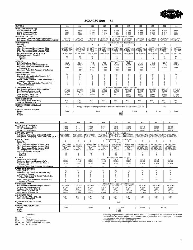
30XA080-500 — SI
LEGEND *Operating weight includes 2 pumps on models 30XA090-160. No pumps are available on 30XA080 or30XA180-500. All weights include coil trim panels. See pages 8-19 for mounting weights for units with-out pumps and units with single pump packages.
†30XA080 unit does not have an economizer.**The high ambient temperature option is not available on 30XA080-120 units.
UNIT 30XA 080 090 100 110 120 140 160 180 200 220
OPERATING WEIGHT (kg)*Al-Cu Condenser Coils 3 481 4 517 4 620 4 684 4 750 5 788 5 898 6 164 6 220 6 680Cu-Cu Condenser Coils 3 809 4 955 5 058 5 122 5 187 6 335 6 445 6 821 6 876 7 391MCHX Condenser Coils 3 281 4 255 4 356 4 417 4 480 5 454 5 559 5 760 5 811 6 236
REFRIGERANT TYPE R-134a, EXV Controlled SystemRefrigerant Charge (kg) Ckt A/Ckt B/Ckt C 50/50/— 50/50/— 54/54/— 61/61/— 61/61/— 92/55/— 102/72/— 93/93/— 102/102— 112/102/—Refrigerant Charge (kg) Ckt A/Ckt B/Ckt C (MCHX) 44.5/44.5/— 42.6/42.6/— 43.6/43.6/— 45.4/45.4/— 43.4/43.4/— 62.1/43.6/— 62.1/45.3/— 64.0/64.0/— 73.0/73.0/— 77.1/73.0/—
COMPRESSORS Semi-Hermetic Twin Rotary ScrewsQuantity 2 2 2 2 2 2 2 2 2 2Speed (r/s) 58.3(Qty) Compressor Model Number Ckt A (1) 06TS-137† (1) 06TS-137 (1) 06TS-155 (1) 06TS-186 (1) 06TS-186 (1) 06TT-266 (1) 06TT-301 (1) 06TT-266 (1) 06TT-301 (1) 06TT-356(Qty) Compressor Model Number Ckt B (1) 06TS-137† (1) 06TS-137 (1) 06TS-155 (1) 06TS-155 (1) 06TS-186 (1) 06TS-155 (1) 06TS-186 (1) 06TT-266 (1) 06TT-301 (1) 06TT-301(Qty) Compressor Model Number Ckt C N/A N/A N/A N/A N/A N/A N/A N/A N/A N/AOil Charge (liters), Ckt A/Ckt B/Ckt C 20.8/20.8/— 20.8/20.8/— 20.8/20.8/— 20.8/20.8/— 20.8/20.8/— 23.7/20.8/— 23.7/23.7/— 23.7/23.7/— 23.7/23.7/— 25.6/23.7/—Minimum Capacity Step (%)
Standard 15 15 15 14 15 11 11 15 15 14Optional 9 9 9 8 10 7 8 10 10 10
COOLER Flooded, Shell and Tube TypeNet Fluid Volume (liters) 62.5 70.0 70.0 75.7 87.1 96.5 104.1 119.2 128.7 140.1Maximum Refrigerant Pressure (kPa) 1516.8 1516.8 1516.8 1516.8 1516.8 1516.8 1516.8 1516.8 1516.8 1516.8Maximum Water Side Pressure Without
Pumps (kPa) 2 068 2 068 2 068 2 068 2 068 2 068 2 068 2 068 2 068 2 068
Maximum Water Side Pressure With Pumps — 1 034 1 034 1 034 1 034 1 034 1 034 — — —
WATER CONNECTIONSDrain (NPT, in.) 3/8 3/8 3/8 3/8 3/8 3/8 3/8 3/8 3/8 3/8Standard, Inlet and Outlet, Victaulic (in.) 5 5 5 5 5 5 5 6 6 6
Number of Passes 2 2 2 2 2 2 2 2 2 2Minus 1 Pass, Inlet and Outlet, Victaulic (in.) 5 5 5 5 5 5 5 8 8 8
Number of Passes 1 1 1 1 1 1 1 1 1 1Plus 1 Pass, Inlet and Outlet, Victaulic (in.) 4 4 4 4 4 5 5 6 6 6
Number of Passes 3 3 3 3 3 3 3 3 3 3
CONDENSER FANS Shrouded Axial Type, Vertical DischargeFan Speed (r/s) Standard/High Ambient** 14.2/— 14.2/— 14.2/— 14.2/— 14.2/— 14.2/19.0 14.2/19.0 14.2/19.0 14.2/19.0 14.2/19.0No. Blades...Diameter (mm) 9...762 9...762 9...762 9...762 9...762 9...762 9...762 9...762 9...762 9...762No. Fans (Ckt A/Ckt B/Ckt C) 3/3/— 4/4/— 4/4/— 4/4/— 4/4/— 6/4/— 6/4/— 6/6/— 6/6/— 7/6/—Total Airflow (L/s) 14.2 r/s 26 335 35 113 35 113 35 113 35 113 43 891 43 891 52 669 52 669 57 059Total Airflow (L/s) 19.0 r/s — — — — — 58 522 58 522 70 226 70 226 76 078
CONDENSER COILSNo. Coils (Ckt A/Ckt B/Ckt C) 3/3/— 4/4/— 4/4/— 4/4/— 4/4/— 6/4/— 6/4/— 6/6/— 6/6/— 7/6/—Total Face Area (sq m) 13 17 17 17 17 22 22 26 26 28
HYDRONIC MODULE (Optional)Pump N/A Pump(s) with pressure/temperature taps and combination valve. Single or Dual, 58.3 r/s N/A
CHASSIS DIMENSIONS (mm)Length 3 606 4 800 5 994 7 188 8 382Width 2255Height 2300
UNIT 30XA 240 260 280 300 325 350 400 450 500
OPERATING WEIGHT (kg)*Al-Cu Condenser Coils 6 753 7 644 7 721 7 876 8 543 8 636 11 149 12 066 12 199Cu-Cu Condenser Coils 7 464 8 465 8 542 8 751 9 528 9 621 12 243 13 269 13 402MCHX Condenser Coils 6 304 7 130 7 202 7 322 7 923 8 010 10 450 11 295 11 416
REFRIGERANT TYPE R-134a, EXV Controlled SystemRefrigerant Charge (kg) Ckt A/Ckt B/Ckt C 122.5/122.5/— 170.1/99.8/— 170.1/122.5/— 188.3/122.5/— 170.1/170.1/— 188.3/170.1/— 122.5/122.5/170.1 188.3/102/188.3 188.3/188.3/122.5Refrigerant Charge (kg) Ckt A/Ckt B/Ckt C (MCHX) 77.3/76.4/— 112.3/75.0/— 109.1/77.3/— 111.4/77.3/— 109.1/109.1/— 111.4/109.1/— 77.3/77.3/97.7 107.3/77.3/103.2 110.5/80.5/103.5
COMPRESSORS Semi-Hermetic Twin Rotary ScrewsQuantity 2 2 2 2 2 2 3 3 3Speed (r/s) 3500(Qty) Compressor Model Number Ckt A (1) 06TT-356 (1) 06TU-483 (1) 06TU-483 (1) 06TU-554 (1) 06TU-483 (1) 06TU-554 (1) 06TT-356 (1) 06TU-554 (1) 06TU-554(Qty) Compressor Model Number Ckt B (1) 06TT-356 (1) 06TT-301 (1) 06TT-356 (1) 06TT-356 (1) 06TU-483 (1) 06TU-483 (1) 06TT-356 (1) 06TT-266 (1) 06TT-356(Qty) Compressor Model Number Ckt C N/A N/A N/A N/A N/A N/A (1) 06TU-483 (1) 06TU-554 (1) 06TU-554Oil Charge (liter), Ckt A/Ckt B/Ckt C 25.6/25.6/— 28.4/25.6/— 28.4/25.6/— 28.4/25.6/— 28.4/28.4/— 28.4/28.4/— 25.6/25.6/28.4 28.4/23.7/28.4 28.4/25.6/28.4Minimum Capacity Step (%)
Standard 15 10 13 12 15 14 9 6 7Optional 10 8 9 7 10 10 6 4 5
COOLER Flooded, Shell and Tube TypeNet Fluid Volume (liters) 147.6 159.0 166.6 183.6 191.2 202.1 257.4 283.9 314.2Maximum Refrigerant Pressure (kPa) 1516.8 1516.8 1516.8 1516.8 1516.8 1516.8 1516.8 1516.8 1516.8Maximum Water Side Pressure Without
Pumps (kPa) 2 068 2 068 2 068 2 068 2 068 2 068 2 068 2 068 2 068
Maximum Water Side Pressure With Pumps — — — — — — — — —
WATER CONNECTIONSDrain (NPT, in.) 3/8 3/8 3/8 3/8 3/8 3/8 3/8 3/8 3/8Standard, Inlet and Outlet, Victaulic (in.) 6 8 8 8 8 8 8 8 8
Number of Passes 2 2 2 2 2 2 1 1 1Minus 1 Pass, Inlet and Outlet, Victaulic (in.) 8 8 8 8 8 8 — — —
Number of Passes 1 1 1 1 1 1 — — —Plus 1 Pass, Inlet and Outlet, Victaulic (in.) 6 8 8 8 8 8 — — —
Number of Passes 3 3 3 3 3 3 — — —
CONDENSER FANS Shrouded Axial Type, Vertical DischargeFan Speed (r/s) Standard/High Ambient** 14.2/19.0 14.2/19.0 14.2/19.0 14.2/19.0 14.2/19.0 14.2/19.0 14.2/19.0 14.2/19.0 14.2/19.0No. Blades...Diameter (mm) 9...762 9...762 9...762 9...762 9...762 9...762 9...762 9...762 9...762No. Fans (Ckt A/Ckt B/Ckt C) 7/6/— 9/6/— 9/7/— 10/6/— 9/9/— 9/9/— 6/6/8 8/6/8 8/6/8Total Airflow (L/s) 14.2 r/s 57 059 65 837 70 226 70 226 79 004 79 004 87 782 96 561 96 561Total Airflow (L/s) 19.0 r/s 76 078 87 782 93 634 93 634 93 634 105 339 117 043 128 747 128 747
CONDENSER COILSNo. Coils (Ckt A/Ckt B/Ckt C) 7/6/— 9/6/— 9/7/— 10/6/— 9/9/— 9/9/— 6/6/8 8/6/8 8/6/8Total Face Area (sq m) 28 33 35 35 39 39 44 48 48
HYDRONIC MODULE (Optional)Pump N/A
CHASSIS DIMENSIONS (mm)Length 8 382 9 576 10 770 11 964 13 158Width 2 255Height 2 300
Cu — CopperAl — AluminumEXV — Electronic Expansion ValveMCHX — Micro-Channel Heat ExchangerN/A — Not Applicable
8
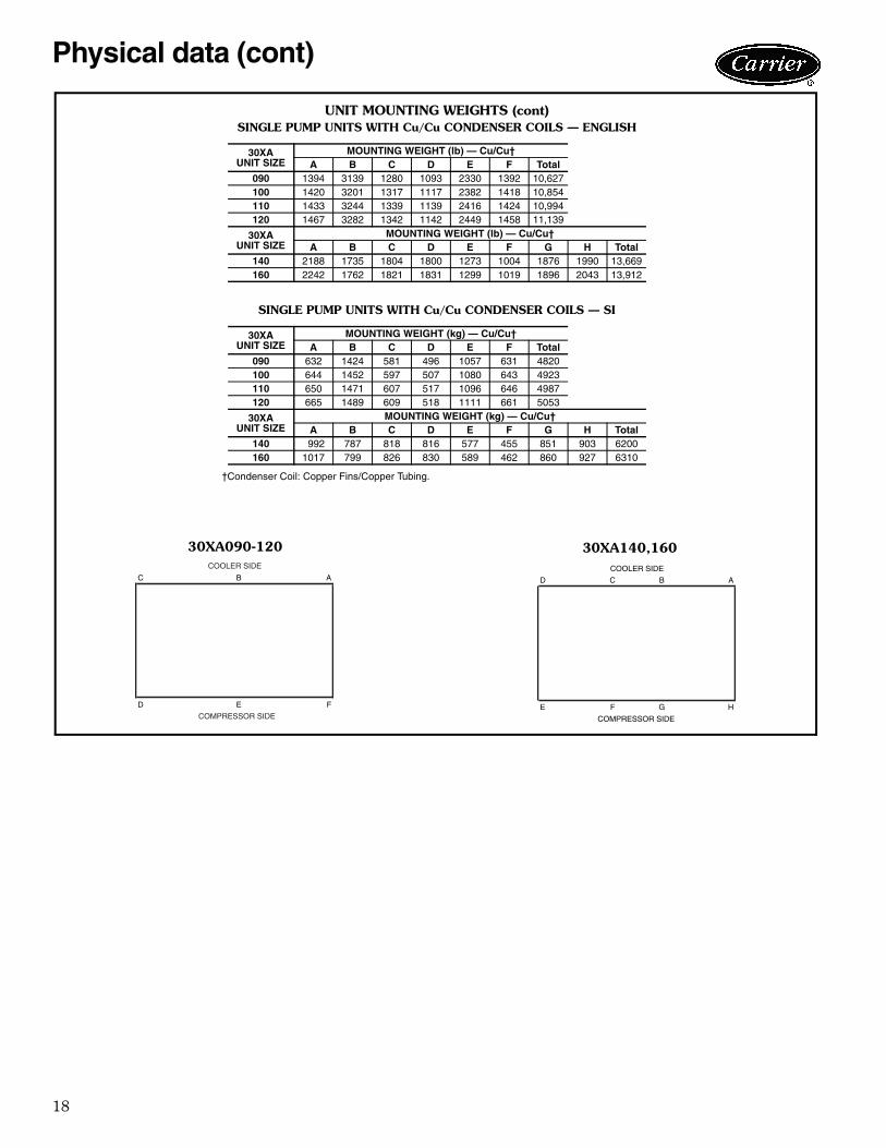
Physical data (cont)
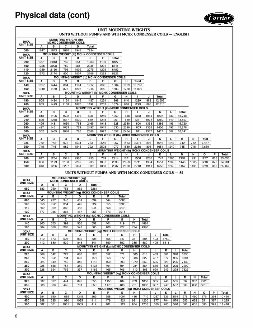
UNIT MOUNTING WEIGHTSUNITS WITHOUT PUMPS AND WITH MCHX CONDENSER COILS — ENGLISH
UNITS WITHOUT PUMPS AND WITH MCHX CONDENSER COILS — SI
30XAUNIT SIZE
MOUNTING WEIGHT (lb)MCHX CONDENSER COILS
A B C D Total080 1947 1673 1670 1943 7234
30XAUNIT SIZE
MOUNTING WEIGHT (lb) MCHX CONDENSER COILSA B C D E F Total
090 1201 2043 750 951 1983 1199 8127100 1226 2098 780 981 2038 1224 8348110 1239 2136 798 1006 2075 1229 8483120 1272 2174 800 1007 2106 1263 8622
30XAUNIT SIZE
MOUNTING WEIGHT (lb) MCHX CONDENSER COILSA B C D E F G H Total
140 1897 1444 864 1181 1217 883 1584 1699 10,768160 1949 1469 878 1206 1246 899 1603 1750 11,000
30XAUNIT SIZE
MOUNTING WEIGHT (lb) MCHX CONDENSER COILSA B C D E F G H I J Total
180 905 1484 1164 1849 1187 1224 1868 840 1289 888 12,699200 909 1499 1188 1870 1192 1232 1879 848 1299 893 12,810
30XAUNIT SIZE
MOUNTING WEIGHT (lb) MCHX CONDENSER COILSA B C D E F G H I J K L Total
220 813 1196 1592 1498 828 1216 1259 848 1363 1064 1237 832 13,748240 829 1218 1617 1520 830 1218 1261 850 1371 1073 1260 849 13,897260 495 1431 1630 763 2465 1013 1528 2380 800 1333 1386 495 15,720280 497 1451 1663 771 2497 1015 1530 2390 803 1358 1406 497 15,878300 502 1465 1686 786 2568 1027 1557 2454 811 1367 1417 502 16,141
30XAUNIT SIZE
MOUNTING WEIGHT (lb) MCHX CONDENSER COILSA B C D E F G H I J K L M N Total
325 742 742 978 1531 783 2546 1067 1563 2334 804 1646 1247 742 742 17,467350 745 745 982 1546 792 2598 1077 1589 2386 808 1651 1249 745 745 17,659
30XAUNIT SIZE
MOUNTING WEIGHT (lb) MCHX CONDENSER COILSA B C D E F G H I J K L M N O P Total
400 847 1234 1511 2965 1255 789 2214 1071 1566 2286 747 1265 2152 991 1277 868 23,038450 856 1179 2160 2282 905 1057 2030 2053 2711 1934 1551 1266 1440 1385 1216 876 24,901500 843 1236 2207 2334 909 1060 2037 2060 2718 1941 1555 1269 1457 1401 1279 863 25,167
30XAUNIT SIZE
MOUNTING WEIGHT (kg)MCHX CONDENSER COILS
A B C D Total080 883 759 758 882 3281
30XAUNIT SIZE
MOUNTING WEIGHT (kg) MCHX CONDENSER COILSA B C D E F Total
090 545 927 340 431 899 544 3686100 556 952 354 445 924 555 3786110 562 969 362 456 941 558 3848120 577 986 363 457 955 573 3911
30XAUNIT SIZE
MOUNTING WEIGHT (kg) MCHX CONDENSER COILSA B C D E F G H Total
140 860 655 392 536 552 401 719 771 4884160 884 666 398 547 565 408 727 794 4990
30XAUNIT SIZE
MOUNTING WEIGHT (kg) MCHX CONDENSER COILSA B C D E F G H I J Total
180 410 673 528 839 538 555 847 381 584 403 5760200 412 680 539 848 541 559 852 385 589 405 5811
30XAUNIT SIZE
MOUNTING WEIGHT (kg) MCHX CONDENSER COILSA B C D E F G H I J K L Total
220 369 542 722 680 376 552 571 385 618 483 561 378 6236240 376 552 734 690 377 553 572 386 622 487 572 385 6304260 225 649 740 346 1118 460 693 1079 363 605 629 225 7130280 225 658 754 350 1133 461 694 1084 364 616 638 225 7202300 228 664 765 357 1165 466 706 1113 368 620 643 228 7322
30XAUNIT SIZE
MOUNTING WEIGHT (kg) MCHX CONDENSER COILSA B C D E F G H I J K L M N Total
325 337 337 444 695 355 1155 484 709 1058 365 746 565 337 337 7923350 338 338 446 701 359 1179 488 721 1082 367 749 567 338 338 8010
30XAUNIT SIZE
MOUNTING WEIGHT (kg) MCHX CONDENSER COILSA B C D E F G H I J K L M N O P Total
400 384 560 685 1345 569 358 1004 486 710 1037 339 574 976 450 579 394 10 450450 388 535 980 1035 411 479 921 931 1230 877 704 574 653 628 551 397 11 295500 382 561 1001 1059 412 481 924 934 1233 880 705 576 661 635 580 391 11 416
9
ABCD
HGFE
COOLER SIDE
COMPRESSOR SIDE
ABCDE
GF H JI
COOLER SIDE
COMPRESSOR SIDE
ABCDEF
LKJIHG
COOLER SIDE
COMPRESSOR SIDE
ABCDEFG
NMLKJIH
COOLER SIDE
COMPRESSOR SIDE
ABCDEFGH
PONMLKJI
COOLER SIDE
COMPRESSOR SIDE
AB
DC
COOLER SIDE
COMPRESSOR SIDE
ABC
FED
COOLER SIDE
COMPRESSOR SIDE
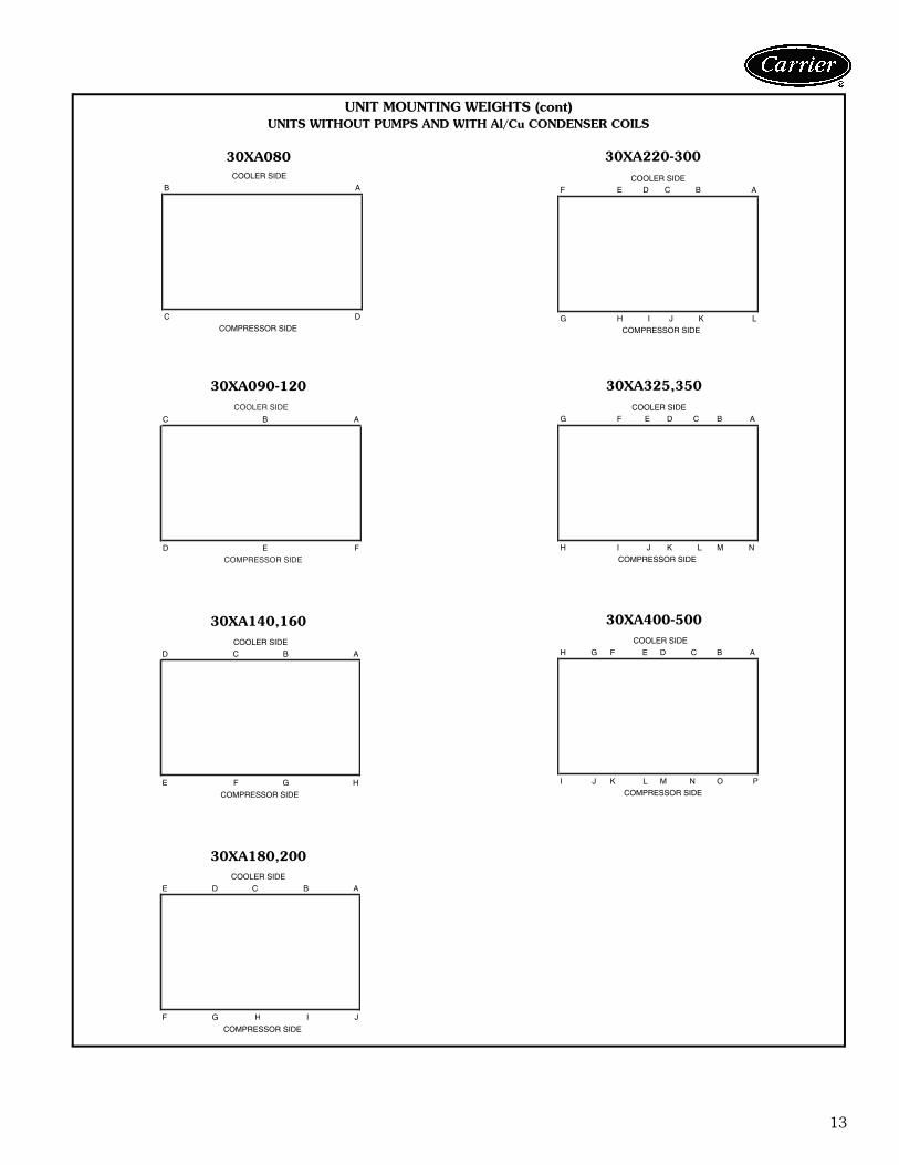
30XA080
30XA090-120
30XA140,160
30XA180,200
30XA220-300
30XA325,350
30XA400-500
LEGENDMCHX — Microchannel Heat Exchanger
a30-4419
a30-4420
a30-4421
a30-4423
a30-4422
a30-4424
a30-4425
UNIT MOUNTING WEIGHTS (cont)UNITS WITHOUT PUMPS AND WITH MCHX CONDENSER COILS
10
Physical data (cont)
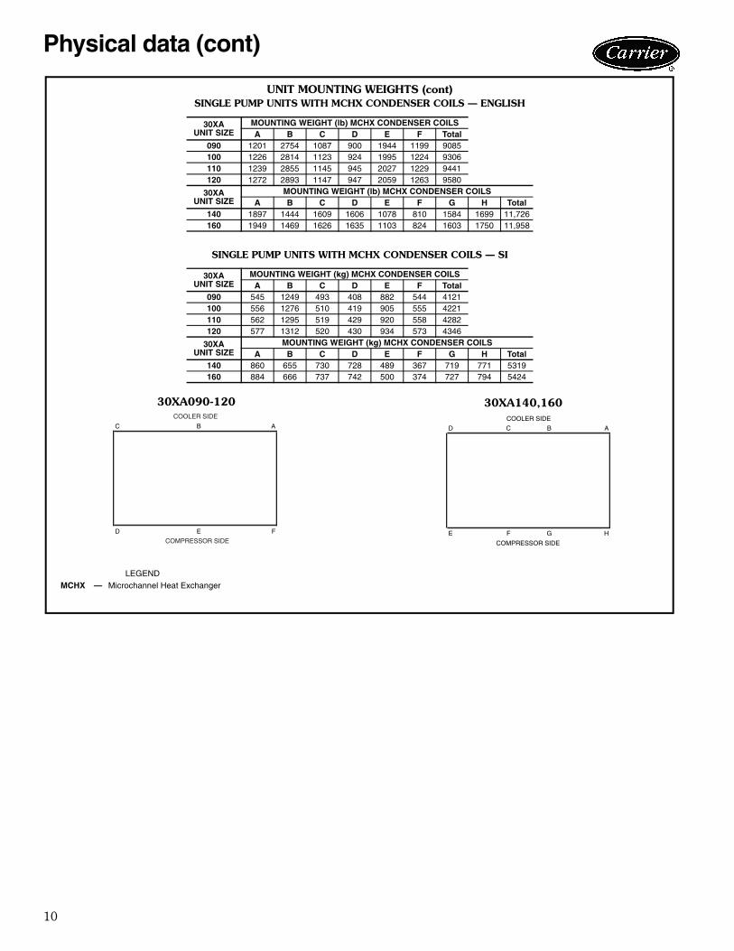
UNIT MOUNTING WEIGHTS (cont)SINGLE PUMP UNITS WITH MCHX CONDENSER COILS — ENGLISH
SINGLE PUMP UNITS WITH MCHX CONDENSER COILS — SI
30XAUNIT SIZE
MOUNTING WEIGHT (lb) MCHX CONDENSER COILSA B C D E F Total
090 1201 2754 1087 900 1944 1199 9085100 1226 2814 1123 924 1995 1224 9306110 1239 2855 1145 945 2027 1229 9441120 1272 2893 1147 947 2059 1263 9580
30XAUNIT SIZE
MOUNTING WEIGHT (lb) MCHX CONDENSER COILSA B C D E F G H Total
140 1897 1444 1609 1606 1078 810 1584 1699 11,726160 1949 1469 1626 1635 1103 824 1603 1750 11,958
30XAUNIT SIZE
MOUNTING WEIGHT (kg) MCHX CONDENSER COILSA B C D E F Total
090 545 1249 493 408 882 544 4121100 556 1276 510 419 905 555 4221110 562 1295 519 429 920 558 4282120 577 1312 520 430 934 573 4346
30XAUNIT SIZE
MOUNTING WEIGHT (kg) MCHX CONDENSER COILSA B C D E F G H Total
140 860 655 730 728 489 367 719 771 5319160 884 666 737 742 500 374 727 794 5424
30XA090-120 30XA140,160
LEGENDMCHX — Microchannel Heat Exchanger
a30-4420 a30-4421
ABC
FED
COOLER SIDE
COMPRESSOR SIDE
ABCD
HGFE
COOLER SIDE
COMPRESSOR SIDE
11
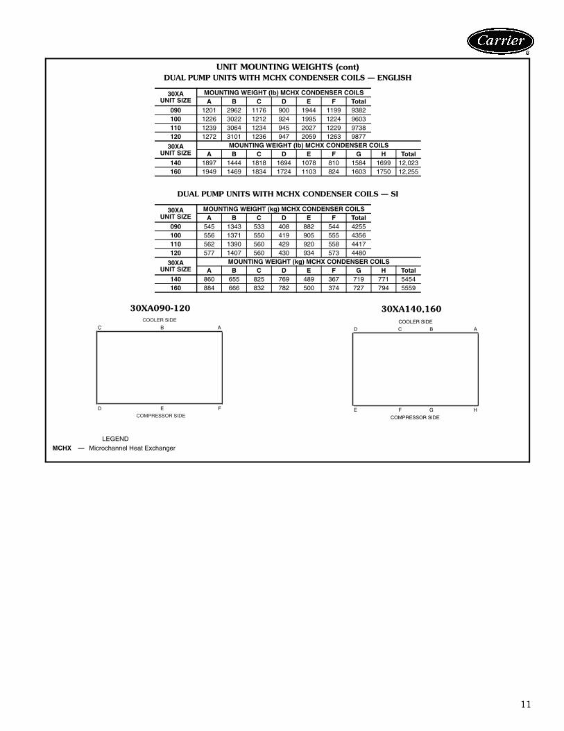
UNIT MOUNTING WEIGHTS (cont)DUAL PUMP UNITS WITH MCHX CONDENSER COILS — ENGLISH
DUAL PUMP UNITS WITH MCHX CONDENSER COILS — SI
30XAUNIT SIZE
MOUNTING WEIGHT (lb) MCHX CONDENSER COILSA B C D E F Total
090 1201 2962 1176 900 1944 1199 9382100 1226 3022 1212 924 1995 1224 9603110 1239 3064 1234 945 2027 1229 9738120 1272 3101 1236 947 2059 1263 9877
30XAUNIT SIZE
MOUNTING WEIGHT (lb) MCHX CONDENSER COILSA B C D E F G H Total
140 1897 1444 1818 1694 1078 810 1584 1699 12,023160 1949 1469 1834 1724 1103 824 1603 1750 12,255
30XAUNIT SIZE
MOUNTING WEIGHT (kg) MCHX CONDENSER COILSA B C D E F Total
090 545 1343 533 408 882 544 4255100 556 1371 550 419 905 555 4356110 562 1390 560 429 920 558 4417120 577 1407 560 430 934 573 4480
30XAUNIT SIZE
MOUNTING WEIGHT (kg) MCHX CONDENSER COILSA B C D E F G H Total
140 860 655 825 769 489 367 719 771 5454160 884 666 832 782 500 374 727 794 5559
30XA090-120 30XA140,160
LEGENDMCHX — Microchannel Heat Exchanger
a30-4420 a30-4421
ABC
FED
COOLER SIDE
COMPRESSOR SIDE
ABCD
HGFE
COOLER SIDE
COMPRESSOR SIDE

12
Physical data (cont)
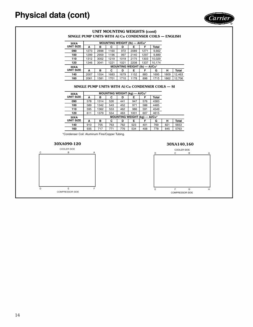
UNIT MOUNTING WEIGHTS (cont)UNITS WITHOUT PUMPS AND WITH Al/Cu CONDENSER COILS — ENGLISH
*Condenser Coil: Aluminum Fins/Copper Tubing.
UNITS WITHOUT PUMPS AND WITH Al/Cu CONDENSER COILS — SI
*Condenser Coil: Aluminum Fins/Copper Tubing.
30XAUNIT SIZE
MOUNTING WEIGHT (lb) — Al/Cu*A B C D Total
080 2059 1785 1778 2051 7674
30XAUNIT SIZE
MOUNTING WEIGHT (lb) — Al/Cu*A B C D E F Total
090 1273 2188 822 1023 2127 1271 8704100 1299 2244 853 1054 2184 1297 8931110 1312 2284 872 1079 2222 1303 9071120 1346 2322 874 1082 2255 1337 9216
30XAUNIT SIZE
MOUNTING WEIGHT (lb) — Al/Cu*A B C D E F G H Total
140 2007 1554 938 1254 1291 957 1695 1809 11,505160 2061 1581 953 1281 1321 974 1715 1862 11,748
30XAUNIT SIZE
MOUNTING WEIGHT (lb) — Al/Cu*A B C D E F G H I J Total
180 979 1558 1239 1998 1261 1298 2016 915 1363 962 13,590200 984 1574 1263 2020 1267 1308 2029 923 1375 968 13,712
30XAUNIT SIZE
MOUNTING WEIGHT (lb) — Al/Cu*A B C D E F G H I J K L Total
220 883 1266 1697 1603 898 1286 1329 918 1468 1169 1307 902 14,727240 900 1288 1723 1626 901 1289 1331 921 1477 1179 1331 920 14,887260 566 1572 1701 834 2607 1084 1599 2521 871 1404 1528 566 16,853280 569 1594 1734 843 2640 1087 1601 2533 875 1429 1549 569 17,022300 578 1617 1762 862 2720 1103 1633 2607 887 1444 1570 578 17,362
30XAUNIT SIZE
MOUNTING WEIGHT (lb) — Al/Cu*A B C D E F G H I J K L M N Total
325 856 856 1054 1607 859 2697 1143 1639 2485 880 1722 1322 856 856 18,834350 860 860 1059 1623 869 2752 1153 1666 2539 885 1727 1326 860 860 19,040
30XAUNIT SIZE
MOUNTING WEIGHT (lb) — Al/Cu*A B C D E F G H I J K L M N O P Total
400 924 1311 1588 3119 1332 866 2368 1148 1643 2440 824 1342 2306 1069 1354 945 24,578450 933 1256 2276 2398 982 1134 2184 2207 2866 2089 1629 1343 1556 1501 1293 953 26,600500 921 1314 2325 2452 987 1139 2194 2217 2875 2098 1633 1348 1575 1519 1357 941 26,894
30XAUNIT SIZE
MOUNTING WEIGHT (kg) — Al/Cu*A B C D Total
080 934 810 807 930 3481
30XAUNIT SIZE
MOUNTING WEIGHT (kg) — Al/Cu*A B C D E F Total
090 578 992 373 464 965 576 3948100 589 1018 387 478 991 588 4051110 595 1036 396 489 1008 591 4115120 611 1053 397 491 1023 607 4181
30XAUNIT SIZE
MOUNTING WEIGHT (kg) — Al/Cu*A B C D E F G H Total
140 910 705 425 569 585 434 769 821 5219160 935 717 432 581 599 442 778 845 5329
30XAUNIT SIZE
MOUNTING WEIGHT (kg) — Al/Cu*A B C D E F G H I J Total
180 444 707 562 906 572 589 915 415 618 436 6164200 446 714 573 916 575 593 920 419 624 439 6220
30XAUNIT SIZE
MOUNTING WEIGHT (kg) — Al/Cu*A B C D E F G H I J K L Total
220 401 574 770 727 407 583 603 416 666 530 593 409 6680240 408 584 782 738 409 585 604 418 670 535 604 417 6753260 257 713 772 378 1182 492 725 1144 395 637 693 257 7644280 258 723 787 382 1197 493 726 1149 397 648 703 258 7721300 262 734 799 391 1234 501 741 1182 402 655 712 262 7876
30XAUNIT SIZE
MOUNTING WEIGHT (kg) — Al/Cu*A B C D E F G H I J K L M N Total
325 388 388 478 729 390 1224 518 744 1127 399 781 600 388 388 8543350 390 390 480 736 394 1248 523 756 1152 401 784 601 390 390 8636
30XAUNIT SIZE
MOUNTING WEIGHT (kg) — Al/Cu*A B C D E F G H I J K L M N O P Total
400 419 595 720 1415 604 393 1074 521 745 1107 374 609 1046 485 614 428 11 149450 423 570 1032 1088 446 514 991 1001 1300 948 739 609 706 681 586 432 12 066500 418 596 1055 1112 448 516 995 1005 1304 952 741 611 714 689 616 427 12 199
13
AB
DC
COOLER SIDE
COMPRESSOR SIDE
ABCD
HGFE
COOLER SIDE
COMPRESSOR SIDE
ABCDE
GF H JI
COOLER SIDE
COMPRESSOR SIDE
ABCDEF
LKJIHG
COOLER SIDE
COMPRESSOR SIDE
ABCDEFG
NMLKJIH
COOLER SIDE
COMPRESSOR SIDE
ABCDEFGH
PONMLKJI
COOLER SIDE
COMPRESSOR SIDE
ABC
FED
COOLER SIDE
COMPRESSOR SIDE
30XA080
30XA090-120
30XA140,160
30XA180,200
30XA220-300
30XA325,350
30XA400-500
a30-4419
a30-4420
a30-4421
a30-4423
a30-4422
a30-4424
a30-4425
UNIT MOUNTING WEIGHTS (cont)UNITS WITHOUT PUMPS AND WITH Al/Cu CONDENSER COILS
14
Physical data (cont)
UNIT MOUNTING WEIGHTS (cont)SINGLE PUMP UNITS WITH Al/Cu CONDENSER COILS — ENGLISH
SINGLE PUMP UNITS WITH Al/Cu CONDENSER COILS — SI
*Condenser Coil: Aluminum Fins/Copper Tubing.
30XAUNIT SIZE
MOUNTING WEIGHT (lb) — Al/Cu*A B C D E F Total
090 1273 2898 1160 972 2089 1271 9,662100 1299 2959 1196 997 2140 1297 9,889110 1312 3002 1219 1019 2175 1303 10,029120 1346 3041 1221 1021 2208 1337 10,174
30XAUNIT SIZE
MOUNTING WEIGHT (lb) — Al/Cu*A B C D E F G H Total
140 2007 1554 1683 1679 1152 883 1695 1809 12,463160 2061 1581 1701 1710 1178 898 1715 1862 12,706
30XAUNIT SIZE
MOUNTING WEIGHT (kg) — Al/Cu*A B C D E F Total
090 578 1314 526 441 947 576 4383100 589 1342 543 452 971 588 4485110 595 1362 553 462 986 591 4549120 611 1379 554 463 1001 607 4615
30XAUNIT SIZE
MOUNTING WEIGHT (kg) — Al/Cu*A B C D E F G H Total
140 910 705 763 762 523 401 769 821 5653160 935 717 771 776 534 408 778 845 5763
30XA090-120 30XA140,160
a30-4420 a30-4421
ABC
FED
COOLER SIDE
COMPRESSOR SIDE
ABCD
HGFE
COOLER SIDE
COMPRESSOR SIDE
15
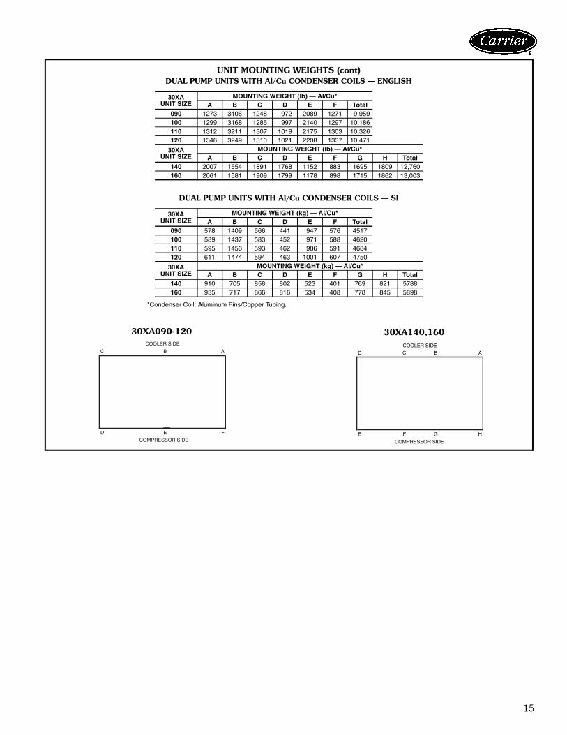
UNIT MOUNTING WEIGHTS (cont)DUAL PUMP UNITS WITH Al/Cu CONDENSER COILS — ENGLISH
DUAL PUMP UNITS WITH Al/Cu CONDENSER COILS — SI
*Condenser Coil: Aluminum Fins/Copper Tubing.
30XAUNIT SIZE
MOUNTING WEIGHT (lb) — Al/Cu*A B C D E F Total
090 1273 3106 1248 972 2089 1271 9,959100 1299 3168 1285 997 2140 1297 10,186110 1312 3211 1307 1019 2175 1303 10,326120 1346 3249 1310 1021 2208 1337 10,471
30XAUNIT SIZE
MOUNTING WEIGHT (lb) — Al/Cu*A B C D E F G H Total
140 2007 1554 1891 1768 1152 883 1695 1809 12,760160 2061 1581 1909 1799 1178 898 1715 1862 13,003
30XAUNIT SIZE
MOUNTING WEIGHT (kg) — Al/Cu*A B C D E F Total
090 578 1409 566 441 947 576 4517100 589 1437 583 452 971 588 4620110 595 1456 593 462 986 591 4684120 611 1474 594 463 1001 607 4750
30XAUNIT SIZE
MOUNTING WEIGHT (kg) — Al/Cu*A B C D E F G H Total
140 910 705 858 802 523 401 769 821 5788160 935 717 866 816 534 408 778 845 5898
30XA090-120 30XA140,160
a30-4420 a30-4421
ABC
FED
COOLER SIDE
COMPRESSOR SIDE
ABCD
HGFE
COOLER SIDE
COMPRESSOR SIDE
16
Physical data (cont)
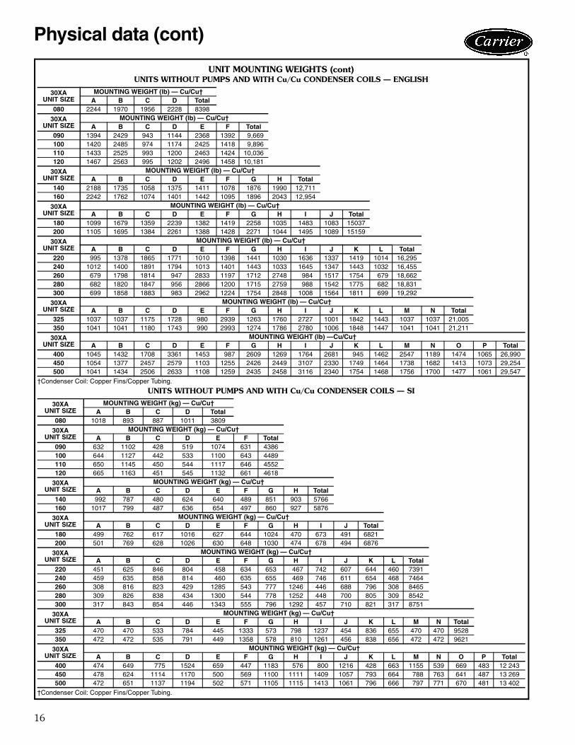
UNIT MOUNTING WEIGHTS (cont)UNITS WITHOUT PUMPS AND WITH Cu/Cu CONDENSER COILS — ENGLISH
†Condenser Coil: Copper Fins/Copper Tubing.
UNITS WITHOUT PUMPS AND WITH Cu/Cu CONDENSER COILS — SI
†Condenser Coil: Copper Fins/Copper Tubing.
30XAUNIT SIZE
MOUNTING WEIGHT (lb) — Cu/Cu†A B C D Total
080 2244 1970 1956 2228 8398
30XAUNIT SIZE
MOUNTING WEIGHT (lb) — Cu/Cu†A B C D E F Total
090 1394 2429 943 1144 2368 1392 9,669100 1420 2485 974 1174 2425 1418 9,896110 1433 2525 993 1200 2463 1424 10,036120 1467 2563 995 1202 2496 1458 10,181
30XAUNIT SIZE
MOUNTING WEIGHT (lb) — Cu/Cu†A B C D E F G H Total
140 2188 1735 1058 1375 1411 1078 1876 1990 12,711160 2242 1762 1074 1401 1442 1095 1896 2043 12,954
30XAUNIT SIZE
MOUNTING WEIGHT (lb) — Cu/Cu†A B C D E F G H I J Total
180 1099 1679 1359 2239 1382 1419 2258 1035 1483 1083 15037200 1105 1695 1384 2261 1388 1428 2271 1044 1495 1089 15159
30XAUNIT SIZE
MOUNTING WEIGHT (lb) — Cu/Cu†A B C D E F G H I J K L Total
220 995 1378 1865 1771 1010 1398 1441 1030 1636 1337 1419 1014 16,295240 1012 1400 1891 1794 1013 1401 1443 1033 1645 1347 1443 1032 16,455260 679 1798 1814 947 2833 1197 1712 2748 984 1517 1754 679 18,662280 682 1820 1847 956 2866 1200 1715 2759 988 1542 1775 682 18,831300 699 1858 1883 983 2962 1224 1754 2848 1008 1564 1811 699 19,292
30XAUNIT SIZE
MOUNTING WEIGHT (lb) — Cu/Cu†A B C D E F G H I J K L M N Total
325 1037 1037 1175 1728 980 2939 1263 1760 2727 1001 1842 1443 1037 1037 21,005350 1041 1041 1180 1743 990 2993 1274 1786 2780 1006 1848 1447 1041 1041 21,211
30XAUNIT SIZE
MOUNTING WEIGHT (lb) —Cu/Cu†A B C D E F G H I J K L M N O P Total
400 1045 1432 1708 3361 1453 987 2609 1269 1764 2681 945 1462 2547 1189 1474 1065 26,990450 1054 1377 2457 2579 1103 1255 2426 2449 3107 2330 1749 1464 1738 1682 1413 1073 29,254500 1041 1434 2506 2633 1108 1259 2435 2458 3116 2340 1754 1468 1756 1700 1477 1061 29,547
30XAUNIT SIZE
MOUNTING WEIGHT (kg) — Cu/Cu†A B C D Total
080 1018 893 887 1011 3809
30XAUNIT SIZE
MOUNTING WEIGHT (kg) — Cu/Cu†A B C D E F Total
090 632 1102 428 519 1074 631 4386100 644 1127 442 533 1100 643 4489110 650 1145 450 544 1117 646 4552120 665 1163 451 545 1132 661 4618
30XAUNIT SIZE
MOUNTING WEIGHT (kg) — Cu/Cu†A B C D E F G H Total
140 992 787 480 624 640 489 851 903 5766160 1017 799 487 636 654 497 860 927 5876
30XAUNIT SIZE
MOUNTING WEIGHT (kg) — Cu/Cu†A B C D E F G H I J Total
180 499 762 617 1016 627 644 1024 470 673 491 6821200 501 769 628 1026 630 648 1030 474 678 494 6876
30XAUNIT SIZE
MOUNTING WEIGHT (kg) — Cu/Cu†A B C D E F G H I J K L Total
220 451 625 846 804 458 634 653 467 742 607 644 460 7391240 459 635 858 814 460 635 655 469 746 611 654 468 7464260 308 816 823 429 1285 543 777 1246 446 688 796 308 8465280 309 826 838 434 1300 544 778 1252 448 700 805 309 8542300 317 843 854 446 1343 555 796 1292 457 710 821 317 8751
30XAUNIT SIZE
MOUNTING WEIGHT (kg) — Cu/Cu†A B C D E F G H I J K L M N Total
325 470 470 533 784 445 1333 573 798 1237 454 836 655 470 470 9528350 472 472 535 791 449 1358 578 810 1261 456 838 656 472 472 9621
30XAUNIT SIZE
MOUNTING WEIGHT (kg) — Cu/Cu†A B C D E F G H I J K L M N O P Total
400 474 649 775 1524 659 447 1183 576 800 1216 428 663 1155 539 669 483 12 243450 478 624 1114 1170 500 569 1100 1111 1409 1057 793 664 788 763 641 487 13 269500 472 651 1137 1194 502 571 1105 1115 1413 1061 796 666 797 771 670 481 13 402

17
AB
DC
COOLER SIDE
COMPRESSOR SIDE
ABC
FED
COOLER SIDE
COMPRESSOR SIDE
ABCD
HGFE
COOLER SIDE
COMPRESSOR SIDE
ABCDE
GF H JI
COOLER SIDE
COMPRESSOR SIDE
ABCDEF
LKJIHG
COOLER SIDE
COMPRESSOR SIDE
ABCDEFG
NMLKJIH
COOLER SIDE
COMPRESSOR SIDE
ABCDEFGH
PONMLKJI
COOLER SIDE
COMPRESSOR SIDE
30XA080
30XA090-120
30XA140,160
30XA180,200
30XA220-300
30XA325,350
30XA400-500
a30-4419
a30-4420
a30-4421
a30-4423
a30-4422
a30-4424
a30-4425
UNIT MOUNTING WEIGHTS (cont)UNITS WITHOUT PUMPS AND WITH Cu/Cu CONDENSER COILS
18
Physical data (cont)
UNIT MOUNTING WEIGHTS (cont)SINGLE PUMP UNITS WITH Cu/Cu CONDENSER COILS — ENGLISH
SINGLE PUMP UNITS WITH Cu/Cu CONDENSER COILS — SI
†Condenser Coil: Copper Fins/Copper Tubing.
30XAUNIT SIZE
MOUNTING WEIGHT (lb) — Cu/Cu†A B C D E F Total
090 1394 3139 1280 1093 2330 1392 10,627100 1420 3201 1317 1117 2382 1418 10,854110 1433 3244 1339 1139 2416 1424 10,994120 1467 3282 1342 1142 2449 1458 11,139
30XAUNIT SIZE
MOUNTING WEIGHT (lb) — Cu/Cu†A B C D E F G H Total
140 2188 1735 1804 1800 1273 1004 1876 1990 13,669160 2242 1762 1821 1831 1299 1019 1896 2043 13,912
30XAUNIT SIZE
MOUNTING WEIGHT (kg) — Cu/Cu†A B C D E F Total
090 632 1424 581 496 1057 631 4820100 644 1452 597 507 1080 643 4923110 650 1471 607 517 1096 646 4987120 665 1489 609 518 1111 661 5053
30XAUNIT SIZE
MOUNTING WEIGHT (kg) — Cu/Cu†A B C D E F G H Total
140 992 787 818 816 577 455 851 903 6200160 1017 799 826 830 589 462 860 927 6310
30XA090-120 30XA140,160
a30-4420 a30-4421
ABC
FED
COOLER SIDE
COMPRESSOR SIDE
ABCD
HGFE
COOLER SIDE
COMPRESSOR SIDE
19
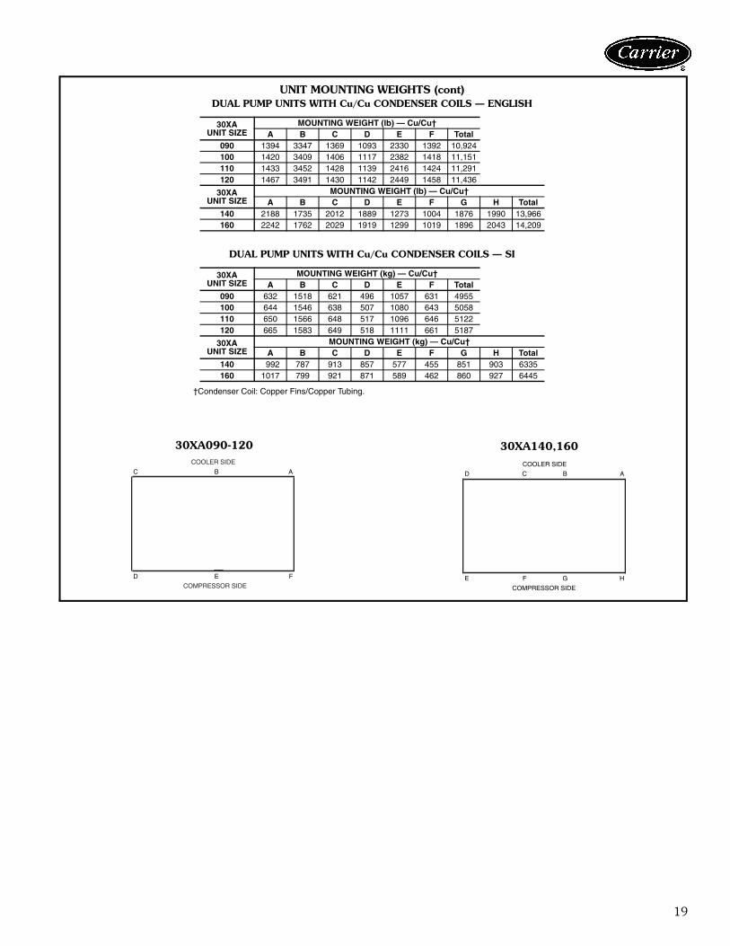
UNIT MOUNTING WEIGHTS (cont)DUAL PUMP UNITS WITH Cu/Cu CONDENSER COILS — ENGLISH
DUAL PUMP UNITS WITH Cu/Cu CONDENSER COILS — SI
†Condenser Coil: Copper Fins/Copper Tubing.
30XAUNIT SIZE
MOUNTING WEIGHT (lb) — Cu/Cu†A B C D E F Total
090 1394 3347 1369 1093 2330 1392 10,924100 1420 3409 1406 1117 2382 1418 11,151110 1433 3452 1428 1139 2416 1424 11,291120 1467 3491 1430 1142 2449 1458 11,436
30XAUNIT SIZE
MOUNTING WEIGHT (lb) — Cu/Cu†A B C D E F G H Total
140 2188 1735 2012 1889 1273 1004 1876 1990 13,966160 2242 1762 2029 1919 1299 1019 1896 2043 14,209
30XAUNIT SIZE
MOUNTING WEIGHT (kg) — Cu/Cu†A B C D E F Total
090 632 1518 621 496 1057 631 4955100 644 1546 638 507 1080 643 5058110 650 1566 648 517 1096 646 5122120 665 1583 649 518 1111 661 5187
30XAUNIT SIZE
MOUNTING WEIGHT (kg) — Cu/Cu†A B C D E F G H Total
140 992 787 913 857 577 455 851 903 6335160 1017 799 921 871 589 462 860 927 6445
30XA090-120 30XA140,160
a30-4420 a30-4421
ABC
FED
COOLER SIDE
COMPRESSOR SIDE
ABCD
HGFE
COOLER SIDE
COMPRESSOR SIDE
20
LEGEND
Factory-installed optionsCondenser coil options are available to match coil con-struction to the site conditions for the best durability. Referto the Condenser Coil Corrosion Protection Options tableon page 22 or the appropriate selection guide for moreinformation.High ambient temperature option provides high-speed condenser fan motors to increase the condenser air-flow. This option may allow for an increase in machinecapacity, and may also result the selection of a smallerchassis to meet given capacity requirements. The highambient temperature option is not available on 30XA080-120 units. This option is required for 30XA400-500 unitswhich are either operating in multi-chiller configurations orhave ambient temperatures at or above 100 F (37.8 C).Minus-one-pass cooler provides a lower pressure dropthrough the cooler for applications with low delta T
(temperature) or high flow or where the coolers are pipedin a series arrangement.Plus-one-pass cooler provides a greater efficiency forbrine applications and in applications with a high delta Tand low flow.Wye-delta start is an alternate starting method whichreduces the in-rush current when starting the compressor.Compressor suction service valve provides additionalprotection. Standard refrigerant discharge isolation and liq-uid valves enable service personnel to store the refrigerantcharge in the cooler or condenser during servicing. Thisfactory-installed option allows for isolation of the compres-sor from the cooler vessel.Energy management module provides energy manage-ment capabilities to minimize chiller energy consumption.Several features are provided with this module includingleaving fluid temperature reset, cooling set point ordemand limit control from a 4 to 20 mA signal, space
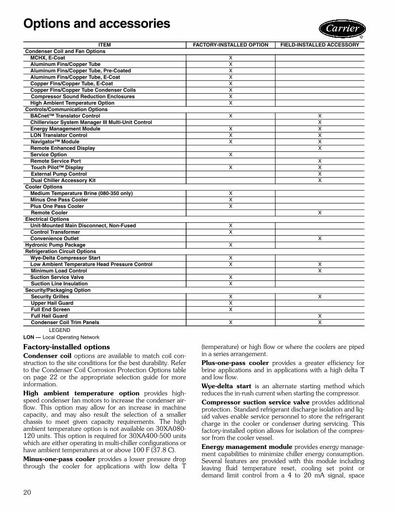
ITEM FACTORY-INSTALLED OPTION FIELD-INSTALLED ACCESSORYCondenser Coil and Fan Options
MCHX, E-Coat XAluminum Fins/Copper Tube XAluminum Fins/Copper Tube, Pre-Coated XAluminum Fins/Copper Tube, E-Coat XCopper Fins/Copper Tube, E-Coat XCopper Fins/Copper Tube Condenser Coils X
Compressor Sound Reduction Enclosures XHigh Ambient Temperature Option X
Controls/Communication OptionsBACnet™ Translator Control X XChillervisor System Manager III Multi-Unit Control XEnergy Management Module X XLON Translator Control X X
Navigator™ Module X XRemote Enhanced Display XService Option XRemote Service Port X
Touch Pilot™ Display X X External Pump Control X Dual Chiller Accessory Kit XCooler Options
Medium Temperature Brine (080-350 only) XMinus One Pass Cooler XPlus One Pass Cooler X
Remote Cooler XElectrical Options
Unit-Mounted Main Disconnect, Non-Fused XControl Transformer XConvenience Outlet X
Hydronic Pump Package XRefrigeration Circuit Options
Wye-Delta Compressor Start XLow Ambient Temperature Head Pressure Control X X
Minimum Load Control XSuction Service Valve X
Suction Line Insulation XSecurity/Packaging Option Security Grilles X X Upper Hail Guard X Full End Screen X Full Hail Guard X Condenser Coil Trim Panels X X
LON — Local Operating Network
Options and accessories
21
temperature reset (requires field-installed space tempera-ture sensor), 2-step demand limit control (from 0 to 100%)activated by a remote contact closure, and discrete inputfor “Ice Done” indication for ice storage system interface.Service option provides a remote service port for Navi-gator™ display connection (sizes 080-120, not required onother sizes) and a factory-installed convenience outlet thatincludes 4-amp GFI (ground fault interrupt) receptacle.Convenience outlet is 115-v female receptacle. Serviceoption not available with 380-v units, and is also availableas a field-installed accessory.Low ambient temperature head pressure controlpermits operation of the 30XA units to –20 F (–29 C) out-door ambient temperature. The control is also available asa field-installed accessory and may require field-installedwind baffles.Medium temperature brine option allows for leavingfluid temperatures to be set below 30 F (–1.1 C). The low-est allowable leaving fluid temperature is a function of brinetype. Further when this option is employed, machineparameters and operating conditions are a function ofchiller size as well as brine type. Low ambient temperaturehead pressure control and suction line insulation arerequired when the medium temperature brine option isinstalled. This option is available on sizes 080-350 only. The chart below shows the parameters associated withmedium temperature brine applications.
LEGENDEG — Ethylene GlycolPG — Propylene Glycol* Leaving fluid temperature less than 32 F (0° C).
Unit-mounted non-fused disconnect option providesnon-fused disconnect for unit power located at the unit.Suction line insulation is tubular closed-cell insulation.This option is required with the medium temperature brineoption and recommended for areas of high dewpointswhere condensation may be a concern.BACnet™ translator control provides an interfacebetween the chiller and a BACnet Local Area Network(LAN, i.e., MS/TP EIA-485). The BACnet translator con-trol is also available as a field-installed accessory.LON translator control provides an interface betweenthe chiller and a Local Operating Network (LON, i.e., Lon-Works FT-10A ANSI/EIA-709.1). The LON translatorcontrol is also available as a field-installed accessory.Condenser coil trim panels provide an aesthetic, fin-ished appearance for the condenser coil ends of the com-pressor side of the unit. Condenser coil trim panels are alsoavailable as a field-installed accessory.
Control transformer is sized to supply the needs of thecontrol circuit from the main power supply.Hydronic pump package adds circulating pumps, acombination valve (isolation, modulation and check),strainer, victaulic piping connections, insulation and heat-ers and pressure temperature taps (3). The pumps areavailable in single or dual (lead/lag controlled), coolerpump versions with total dynamic head external to thechiller from approximately 20 to 140 ft (6.1 to 42.7 m).The hydronic pump package is only available for unit sizes30XA090-160.Security grilles are coated grilles that protect the con-denser, cooler and compressors. These are also availableas an accessory.Upper hail guard consists of louvered panels on the endsof the machine, which firmly fasten to the machine frameand provide coverage from the top of the unit to the bot-tom of the coil. A hinged accessory hail guard is also avail-able. The accessory covers the entire unit end (both ends),and, with its hinged design, is not identical to this option.Full end screen consists of louvered panels on the endsof the machine, providing complete coverage from the topto the bottom of the unit. This option functions as both aprivacy screen and a hail guard. For hail protection, anaccessory hail guard is also available. The accessory coversthe entire unit end (both ends), and, with its hinged design,is not identical to this option.Compressor enclosures provide sound reduction forthe screw compressors.Navigator™ module provides a portable, hand-held dis-play for convenient access to unit status, operation, config-uration and troubleshooting diagnostics capability.Touch Pilot™ display provides a touch screen user inter-face. This fixed screen display can be used to commission,monitor and control Carrier Comfort Network® devices. Itprovides access to configuration, maintenance, service, setpoint, time schedule, alarm history and status data.
Field-installed accessoriesTouch Pilot display used as an accessory is a cost-effec-tive, touch-screen, remote mount device that can be usedin lieu of the remote enhanced display.Remote enhanced display is a remotely mountedindoor 40-character per line, 16-line display panel for unitmonitoring and diagnostics.Remote cooler kit allows for remote installation of thecooler. Never bury refrigerant lines when using this acces-sory or in any other application.Chillervisor System Manager III multi-unit controlallows sequencing of between two and eight chillers inparallel.Low ambient temperature head pressure controlpermits operation of the 30XA units to –20 F (–29 C) out-door ambient temperature. The control is also available asa factory-installed option and may require field-installedwind baffles.Energy management module provides energy manage-ment capabilities to minimize chiller energy consumption.
PARAMETER 30XASIZES
BRINE TYPEEG PG
Cooler Passes 080-350 3 (or +1) 3 (or +1)Minimum Leaving Fluid Temperature 080-350 21.2 F 26.6 F
Maximum Glycol 080-350 35% 33%
Allowable CoolerDelta Temperature*
080-090 2.0 to 7.2 delta F
2.0 to 5.4 delta F
100-350 2.0 to 7.2 delta F
2.0 to 7.2 delta F
22
Several features are provided with this module includingleaving fluid temperature reset, cooling set point, spacetemperature reset (requires field-installed space tempera-ture sensor) or demand limit control from a 4 to 20 mAsignal, 2-step demand limit control (from 0 to 100%) acti-vated by a remote contact closure (one-step demand limitdoes not require the energy management module), and dis-crete input for “Ice Done” indication for ice storage systeminterface.Remote service port consists of a receptacle for Naviga-tor device connection. The port is housed in a waterproofenclosure conveniently located for easy access to informa-tion during operation and maintenance routines.Navigator™ module is required when there is a need fora portable hand-held display, and the main display is aTouch Pilot™ display.Convenience outlet includes 4-amp GFI (ground faultinterrupt) receptacle. Convenience outlet is 115-v femalereceptacle. Not available with 380-v units.BACnet™ translator control provides an interfacebetween the chiller and a BACnet Local Area Network(LAN, i.e., MS/TP EIA-485). The BACnet translator con-trol is also available as a factory-installed option.LON translator control provides an interface betweenthe chiller and a Local Operating Network (LON, i.e.,
LonWorks FT-10A ANSI/EIA-709.1). The LON translatorcontrol is also available as a factory-installed option.Condenser coil trim panels provide an aesthetic, fin-ished appearance for the condenser coil ends of the com-pressor side of the unit. Condenser coil trim panels are alsoavailable as a factory-installed option.Full hail guard consists of hinged, louvered panels,which cover both ends of the unit. This accessory providescomplete protection from hail and flying debris. For hailprotection, two factory options are also available. Theseoptions directly fasten to the end of the chillers (are nothinged), and therefore are not identical to this accessory.Minimum load control allows additional capacity reduc-tion for unit operation below the minimum step of unload-ing via hot gas bypass.External pump control allows the chiller to control dual,external pumps. This accessory is not required for single,external pumps or factory-installed pumps.Security grilles are coated grilles that protect the con-denser, cooler, and compressors. These are also availableas a factory-installed option.Dual chiller accessory kit provides the additional hard-ware (thermistors, wells, connectors) required for applica-tions with 2 chillers running in parallel.
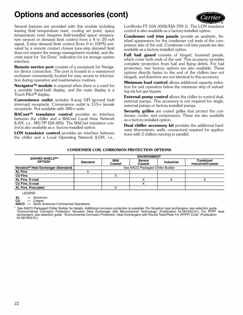
CONDENSER COIL CORROSION PROTECTION OPTIONS
LEGEND
* See NACO Packaged Chiller Builder for details. Additional corrosion protection is available. For Novation heat exchangers, see selection guide“Environmental Corrosion Protection, Novation Heat Exchanger with Microchannel Technology” (Publication 04-581042-01). For RTPF heatexchangers, see selection guide “Environmental Corrosion Protection, Heat Exchangers with Round Tube/Plate Fin (RTPF) Coils” (Publication 04-581043-01).
ENVIRO-SHIELD™OPTION*
ENVIRONMENT
Standard MildCoastal
SevereCoastal Industrial Combined
Industrial/CoastalNovation® Heat Exchanger (Standard) See NACO Packaged Chiller BuilderAL Fins XCU Fins XAL Fins, E-coat X X XCU Fins, E-coat XAL Fins, Precoated X
AL — AluminumCU — CopperNACO — North American Commercial Operations
Options and accessories (cont)
23
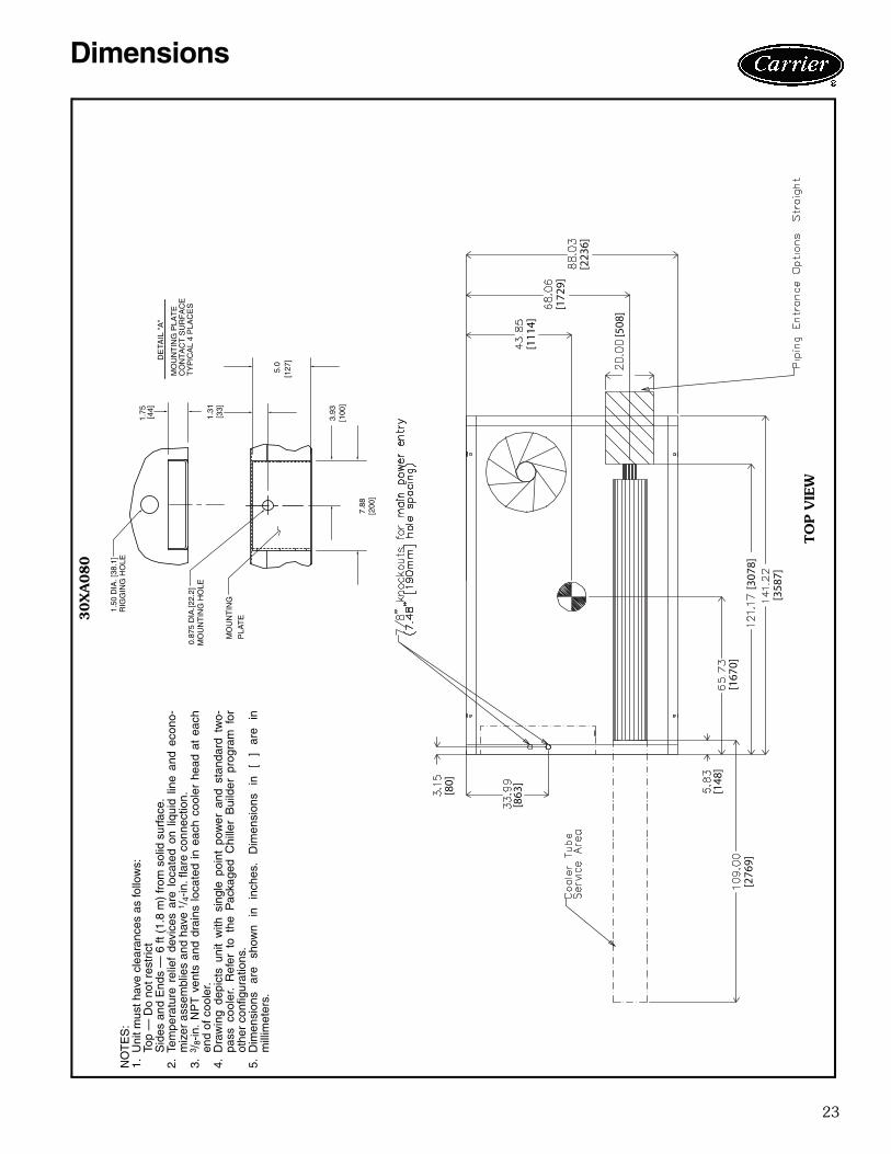
3.93
7.88
[200
]
DE
TAIL
"A
"
MO
UN
TIN
G P
LAT
EC
ON
TA
CT
SU
RF
AC
ET
YP
ICA
L 4
PLA
CE
S
[100
]
MO
UN
TIN
G H
OLE
0.87
5 D
IA.[2
2.2]
MO
UN
TIN
G
PLA
TE
1.50
DIA
. [38
.1]
RIG
GIN
G H
OLE
[127
]5.
0
[33]
1.31
1.75 [44]
[111
4]
[172
9]
[223
6]
[508
]
[167
0]
[358
7]
[307
8]
[148
]
[276
9]
[80]
[863
]
30X
A080
NO
TE
S:
1.U
nit m
ust h
ave
clea
ranc
es a
s fo
llow
s:To
p —
Do
not r
estr
ict
Sid
es a
nd E
nds
— 6
ft (
1.8
m)
from
sol
id s
urfa
ce.
2.Te
mpe
ratu
re r
elie
f de
vice
s ar
e lo
cate
d on
liq
uid
line
and
econ
o-m
izer
ass
embl
ies
and
have
1/ 4
-in. f
lare
con
nect
ion.
3.3 /
8-in
. N
PT
ven
ts a
nd d
rain
s lo
cate
d in
eac
h co
oler
hea
d at
eac
hen
d of
coo
ler.
4.D
raw
ing
depi
cts
unit
with
sin
gle
poin
t po
wer
and
sta
ndar
d tw
o-pa
ss c
oole
r. R
efer
to
the
Pac
kage
d C
hille
r B
uild
er p
rogr
am f
orot
her
conf
igur
atio
ns.
5.D
imen
sion
s ar
e sh
own
in
inch
es.
Dim
ensi
ons
in
[ ]
are
inm
illim
eter
s.
a30-4402
TO
P V
IEW
Dimensions
24
5" V
icta
ulic
Ent
erin
g W
ater
5" V
icta
ulic
Lea
ving
Wat
er
90.5
5[2
300]
19.0
6[4
84]
10.8
[274
]
88.
04
[223
6]68.0
6 [1
729]
[122
3][1
47]
[230
0]
[119
9]
[564
]
[223
6]
[863
][8
74]
[531
]
[564
]
[881
]
8.8
[224
]
3/4
NP
T R
elie
fC
onn.
Fem
ale
5" V
icta
ulic
E
nter
ing
Wat
er
5" V
icta
ulic
Le
avin
g W
ater
Coo
ler V
ent
3/8
NP
T
Coo
ler
Dra
in3/
8 N
PT M
ount
ing
Hol
es
Rig
ging
Hol
es(S
ee D
etai
l A)
Con
trol
Box
All
Vol
tage
s
90.5
5[2
300]
19.0
6[4
84]
10.8
[274
]
141.
22
[358
7]
121.
17
[307
8]
109.
03
[276
9]16
.1 [4
09]
3.15
[80]
a30-4403
30X
A080 (co
nt)
LEFT
EN
D V
IEW
RIG
HT E
ND
VIE
W
FRO
NT V
IEW
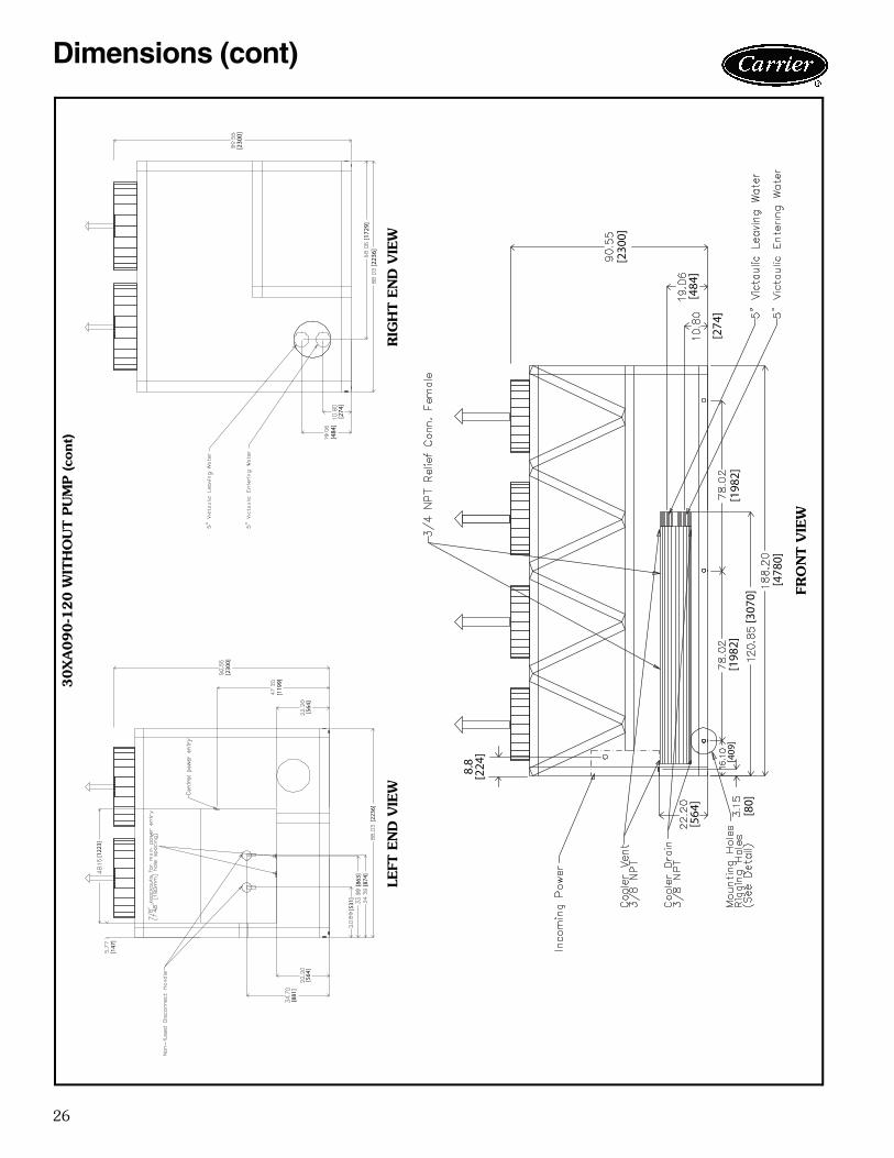
Dimensions (cont)
25
A
[147
5][1
729]
[223
6]
[913
]
[508
]
[127
0]
[478
0][3
070]
B
[140
]
[276
9]
[80]
[863
]
NO
TE
S:
1.U
nit m
ust h
ave
clea
ranc
es a
s fo
llow
s:To
p —
Do
not r
estr
ict
Sid
es a
nd E
nds
— 6
ft (
1.8
m)
from
sol
id s
urfa
ce.
2.Te
mpe
ratu
re r
elie
f de
vice
s ar
e lo
cate
d on
liq
uid
line
and
econ
omiz
er a
ssem
-bl
ies
and
have
1/ 4
-in. f
lare
con
nect
ion.
3.3 /
8-in
. NP
T v
ents
and
dra
ins
loca
ted
in e
ach
cool
er h
ead
at e
ach
end
of c
oole
r.4.
Dra
win
g de
pict
s un
it w
ith s
ingl
e-po
int
pow
er a
nd s
tand
ard
two-
pass
coo
ler.
Ref
er to
the
Pac
kage
d C
hille
r B
uild
er p
rogr
am fo
r ot
her
conf
igur
atio
ns.
5.D
imen
sion
s ar
e sh
own
in in
ches
. Dim
ensi
ons
in [
] are
in m
illim
eter
s.
30X
A U
NIT
AB
090
44.1
1 [1
120]
86.9
3 [2
208]
100
44.1
1 [1
120]
87.2
2 [2
215]
110
44.1
1 [1
120]
87.6
2 [2
226]
120
44.1
1 [1
120]
87.1
2 [2
213]
a30-4404
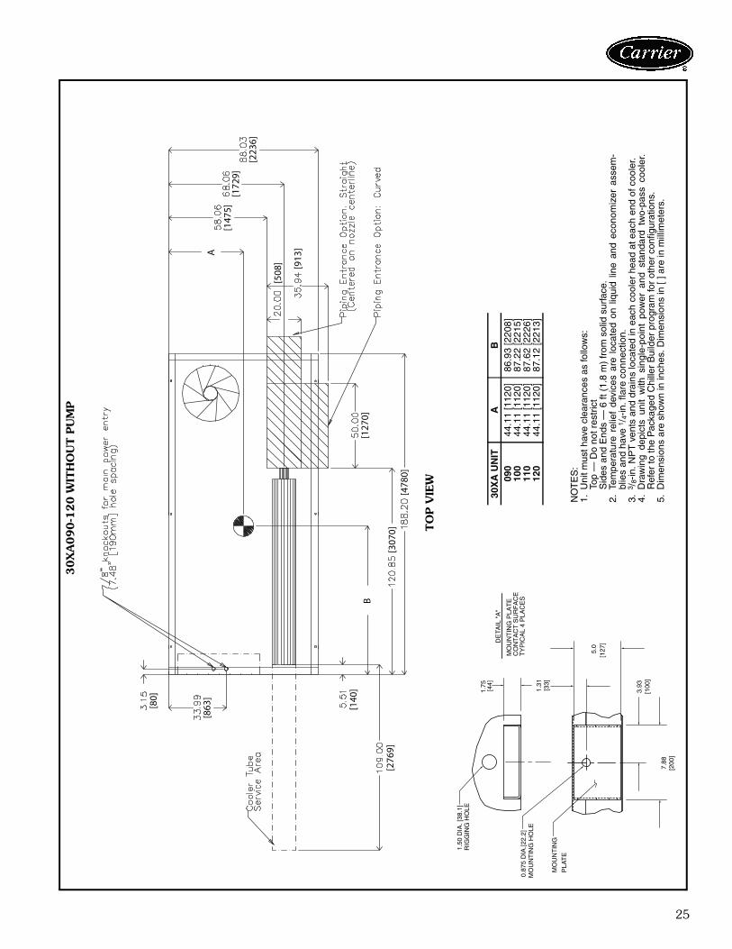
30X
A090-1
20 W
ITH
OU
T P
UM
P
3.93
7.88
[200
]
DE
TAIL
"A
"
MO
UN
TIN
G P
LAT
EC
ON
TA
CT
SU
RF
AC
ET
YP
ICA
L 4
PLA
CE
S
[100
]
MO
UN
TIN
G H
OLE
0.87
5 D
IA.[2
2.2]
MO
UN
TIN
G
PLA
TE
1.50
DIA
. [38
.1]
RIG
GIN
G H
OLE
[127
]5.
0
[33]
1.31
1.75 [44]
TO
P V
IEW
26
[230
0]
[172
9][2
236]
[274
][4
84]
[230
0]
[119
9]
[564
]
[223
6][8
74]
[863
][5
31]
[564
]
[881
]
[147
]
[122
3]
[230
0]
[484
]
[274
]
[198
2]
[478
0]
[198
2][3
070]
[80]
[564
]
[409
]
8.8
[224
]
a30-4405
30X
A090-1
20 W
ITH
OU
T P
UM
P (co
nt)
RIG
HT E
ND
VIE
WLE
FT E
ND
VIE
W
FRO
NT V
IEW
Dimensions (cont)
27
A
[203
2][2
173]
[223
6][2
242]
[356
]
[127
0]
[478
0][4
002]
[342
2]
B
[304
8][2
769]
[80]
[863
]
NO
TE
S:
1.U
nit m
ust h
ave
clea
ranc
es a
s fo
llow
s:To
p —
Do
not r
estr
ict
Sid
es a
nd E
nds
— 6
ft (
1.8
m)
from
sol
id s
urfa
ce.
2.Te
mpe
ratu
re r
elie
f de
vice
s ar
e lo
cate
d on
liq
uid
line
and
econ
omiz
er a
ssem
-bl
ies
and
have
1/ 4
-in. f
lare
con
nect
ion.
3.3 /
8-in
. NP
T v
ents
and
dra
ins
loca
ted
in e
ach
cool
er h
ead
at e
ach
end
of c
oole
r.4.
Dra
win
g de
pict
s un
it w
ith s
ingl
e-po
int
pow
er a
nd s
tand
ard
two-
pass
coo
ler.
Ref
er to
the
Pac
kage
d C
hille
r B
uild
er p
rogr
am fo
r ot
her
conf
igur
atio
ns.
5.D
imen
sion
s ar
e sh
own
in in
ches
. Dim
ensi
ons
in [
] are
in m
illim
eter
s.
30X
A U
NIT
AB
090
44.1
1 [1
120]
86.9
3 [2
208]
100
44.1
1 [1
120]
87.2
2 [2
215]
110
44.1
1 [1
120]
87.6
2 [2
226]
120
44.1
1 [1
120]
87.1
2 [2
213]
a30-4404
30X
A090-1
20 W
ITH
PU
MP
3.93
7.88
[200
]
DE
TAIL
"A
"
MO
UN
TIN
G P
LAT
EC
ON
TA
CT
SU
RF
AC
ET
YP
ICA
L 4
PLA
CE
S
[100
]
MO
UN
TIN
G H
OLE
0.87
5 D
IA.[2
2.2]
MO
UN
TIN
G
PLA
TE
1.50
DIA
. [38
.1]
RIG
GIN
G H
OLE
[127
]5.
0
[33]
1.31
1.75 [44]
TO
P V
IEW
28
90.5
5[2
300]
19.0
6[4
84]
10.2
7[2
61]
88.0
4[2
236]
88.2
8[2
242]
85.5
6[2
173]
5" V
icta
ulic
Lea
ving
Wat
er
5" V
icta
ulic
Ent
erin
g W
ater
[147
][1
223]
[881
]
[564
]
[531
][8
63]
[874
][2
173]
[223
6][2
242]
[261
][4
84]
[564
]
[119
9]
[230
0]
3/4
NP
TR
elie
f Con
n. F
emal
e
Coo
ler
Ven
t3/
8 N
PT
Coo
ler
Dra
in3/
8 N
PT
Mou
ntin
g H
oles
R
iggi
ng H
oles
(See
Det
ailA
)
Con
trol
Box
All
Vol
tage
s
90.5
5[2
300]
19.0
6[4
84]
10.2
7[2
61]
188.
2 [4
780]
157.
54[4
002]
78.0
2 [1
982]
78.0
2 [1
982]
16.1
[409
]
8.8
[224
]
134.
73[3
422]
5" V
icta
ulic
Ent
erin
g W
ater
5" V
icta
ulic
Lea
ving
Wat
er
Dra
in
in
a30-4405
30X
A090-1
20 W
ITH
PU
MP (co
nt)
LEFT
EN
D V
IEW
RIG
HT E
ND
VIE
W
FRO
NT V
IEW
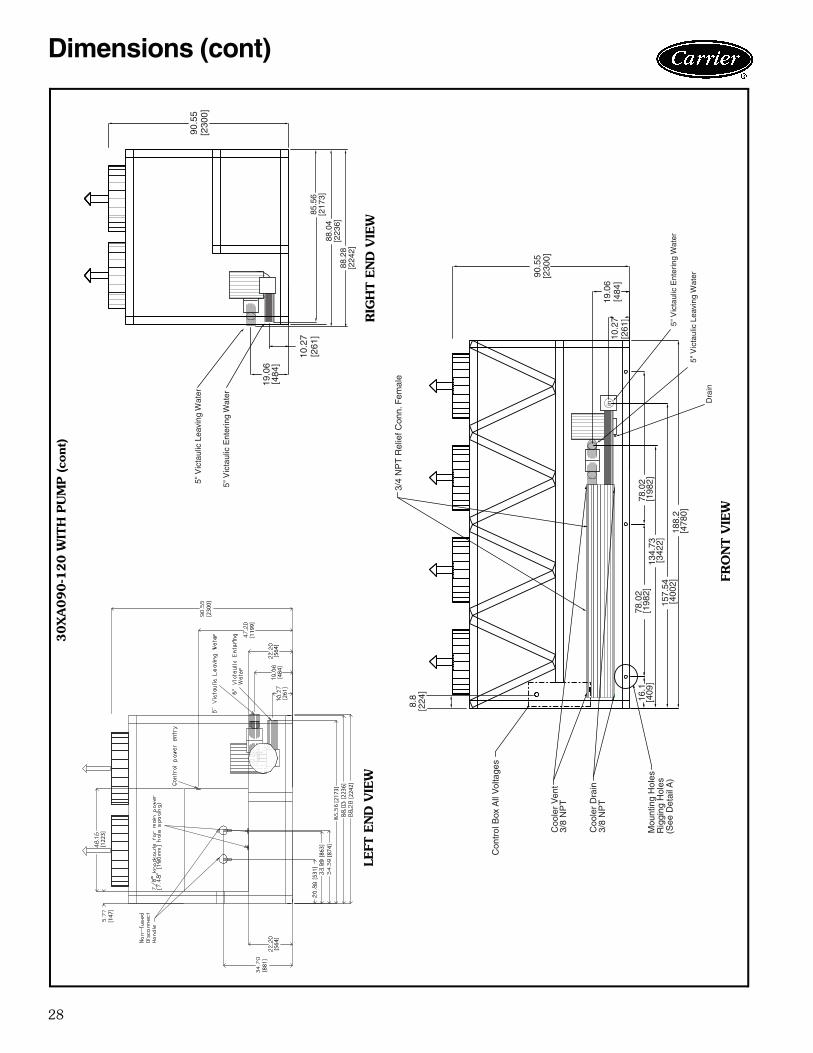
Dimensions (cont)
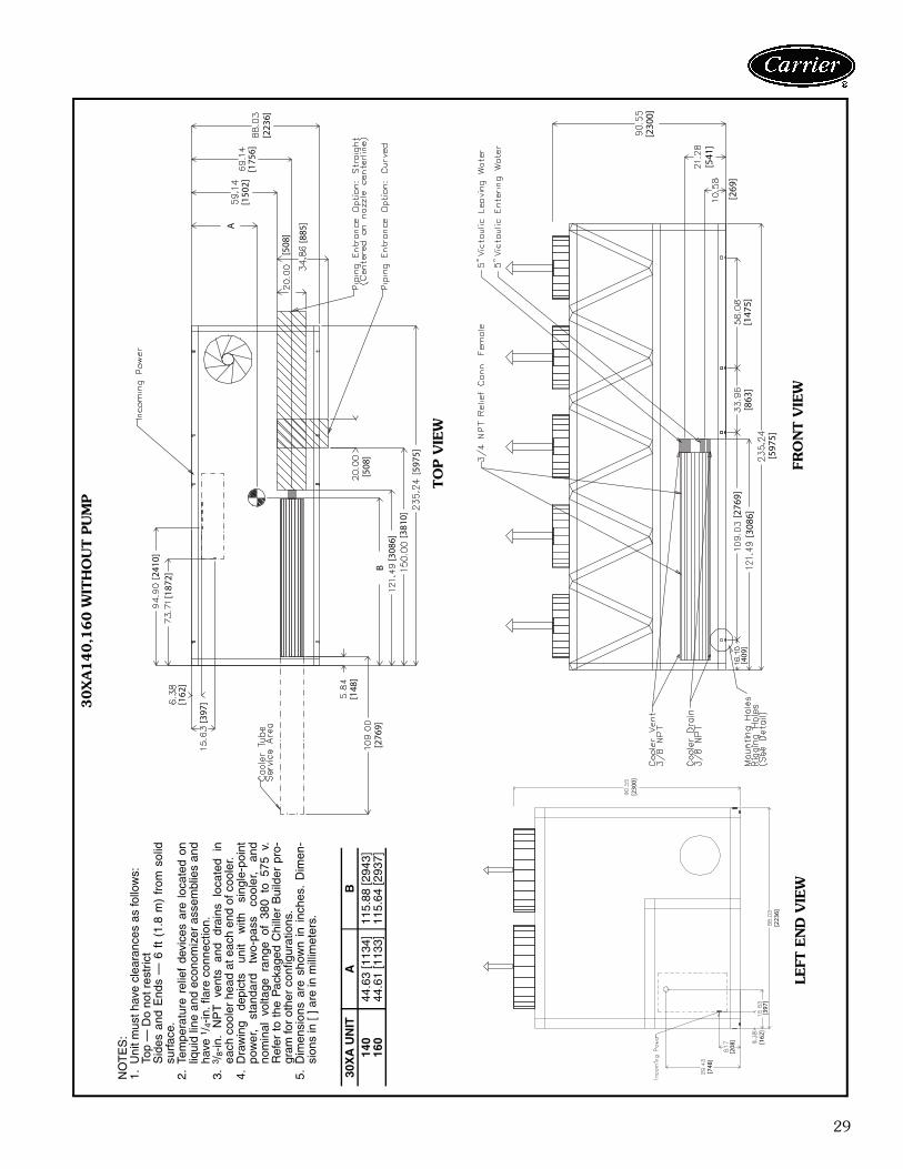
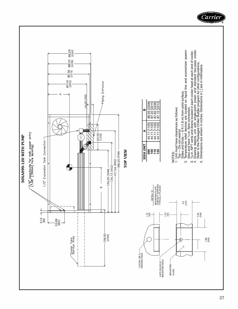
29
[230
0]
[541
]
[269
]
[597
5]
[147
5][8
63]
[308
6][276
9][4
09]
[241
0][1
872]
[162
]
[397
]
[148
]
[276
9][5
08]
B[3
086] [3
810]
[597
5]
[508
]
[885
]
[223
6]
[175
6][1
502]
A
NO
TE
S:
1.U
nit m
ust h
ave
clea
ranc
es a
s fo
llow
s:To
p —
Do
not r
estr
ict
Sid
es a
nd E
nds
— 6
ft
(1.8
m)
from
sol
idsu
rfac
e.2.
Tem
pera
ture
rel
ief
devi
ces
are
loca
ted
onliq
uid
line
and
econ
omiz
er a
ssem
blie
s an
dha
ve 1
/ 4-in
. fla
re c
onne
ctio
n.3.
3 /8-
in.
NP
T
vent
s an
d dr
ains
lo
cate
d in
each
coo
ler
head
at e
ach
end
of c
oole
r.4.
Dra
win
g de
pict
s un
it w
ith
sing
le-p
oint
pow
er,
stan
dard
tw
o-pa
ss
cool
er,
and
nom
inal
vol
tage
ran
ge o
f 38
0 to
575
v.
Ref
er t
o th
e P
acka
ged
Chi
ller
Bui
lder
pro
-gr
am fo
r ot
her
conf
igur
atio
ns.
5.D
imen
sion
s ar
e sh
own
in i
nche
s. D
imen
-si
ons
in [
] are
in m
illim
eter
s.
30X
A U
NIT
AB
140
44.6
3 [1
134]
115.
88 [2
943]
160
44.6
1 [1
133]
115.
64 [2
937]
a30-4404
30X
A140,1
60 W
ITH
OU
T P
UM
P
TO
P V
IEW
FRO
NT V
IEW
LEFT
EN
D V
IEW
[230
0]
[223
6]
[748
]
[208
] [162
][3
97]
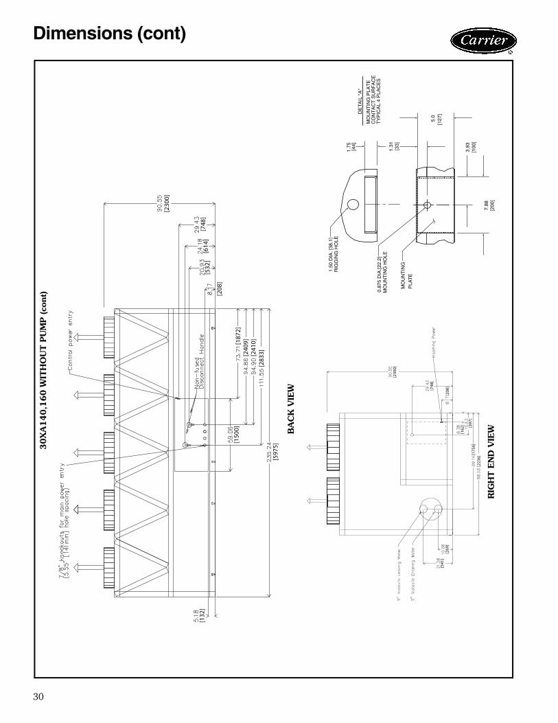
30
[132
]
[150
0]
[597
5]
[187
2][2
409]
[241
0][2
833]
[230
0]
[748
][6
14]
[532
]
[208
]
[230
0]
[748
]
[208
]
[162
] [397
][1
756]
[223
6]
[541
][2
69]
a30-4407
30X
A140,1
60 W
ITH
OU
T P
UM
P (co
nt)
3.93
7.88
[200
]
DE
TAIL
"A
"
MO
UN
TIN
G P
LAT
EC
ON
TA
CT
SU
RF
AC
ET
YP
ICA
L 4
PLA
CE
S
[100
]
MO
UN
TIN
G H
OLE
0.87
5 D
IA.[2
2.2]
MO
UN
TIN
G
PLA
TE
1.50
DIA
. [38
.1]
RIG
GIN
G H
OLE
[127
]5.
0
[33]
1.31
1.75 [44]
BA
CK
VIE
W
RIG
HT E
ND
VIE
W
Dimensions (cont)
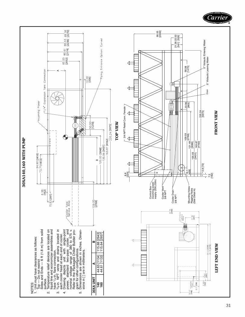
31
[748
]
[208
]
[162
][3
97]
[223
6][2
270]
[541
]
[230
0]
A
[203
2][2
174]
[223
6][2
270]
[356
][1
270]
[276
9]
[397
][162
]
[187
2][241
0]
[597
5][4
162]
[343
1][3
048]
B
3/4
NP
T R
elie
f Con
n. F
emal
e
5" V
icta
ulic
Ent
erin
g 5"
Vic
taul
ic L
eavi
ng W
ater
Wat
er
Coo
ler
Dra
in3/
8 N
PT
Coo
ler
Ven
t3/
8 N
PT
Mou
ntin
g H
oles
R
iggi
ng H
oles
(See
Det
ailA
)
Con
trol
Box
in
com
ing
pow
er
supp
ly (
200,
230v
)
90.5
5[2
300]
22.0
2[5
59]
235.
24[5
975]
121.
49[3
086]
109.
03[2
769]
58.0
8[1
475]
33.9
6[8
63]
16.1
[409
]
8.8
[224
]
7.2
[182
]
2.8
[72]
21.2
8[5
41]
135.
03[3
431]
163.
87[4
162]
inou
t
Dra
in
a30-4407
30X
A140,1
60 W
ITH
PU
MP TO
P V
IEW
FRO
NT V
IEW
LEFT
EN
D V
IEW
NO
TE
S:
1.U
nit m
ust h
ave
clea
ranc
es a
s fo
llow
s:To
p —
Do
not r
estr
ict
Sid
es a
nd E
nds
— 6
ft
(1.8
m)
from
sol
idsu
rfac
e.2.
Tem
pera
ture
rel
ief
devi
ces
are
loca
ted
onliq
uid
line
and
econ
omiz
er a
ssem
blie
s an
dha
ve 1
/ 4-in
. fla
re c
onne
ctio
n.3.
3 /8-
in.
NP
T
vent
s an
d dr
ains
lo
cate
d in
each
coo
ler
head
at e
ach
end
of c
oole
r.4.
Dra
win
g de
pict
s un
it w
ith
sing
le-p
oint
pow
er,
stan
dard
tw
o-pa
ss
cool
er,
and
nom
inal
vol
tage
ran
ge o
f 38
0 to
575
v.
Ref
er t
o th
e P
acka
ged
Chi
ller
Bui
lder
pro
-gr
am fo
r ot
her
conf
igur
atio
ns.
5.D
imen
sion
s ar
e sh
own
in i
nche
s. D
imen
-si
ons
in [
] are
in m
illim
eter
s.
30X
A U
NIT
AB
140
44.6
3 [1
134]
115.
88 [2
943]
160
44.6
1 [1
133]
115.
64 [2
937]
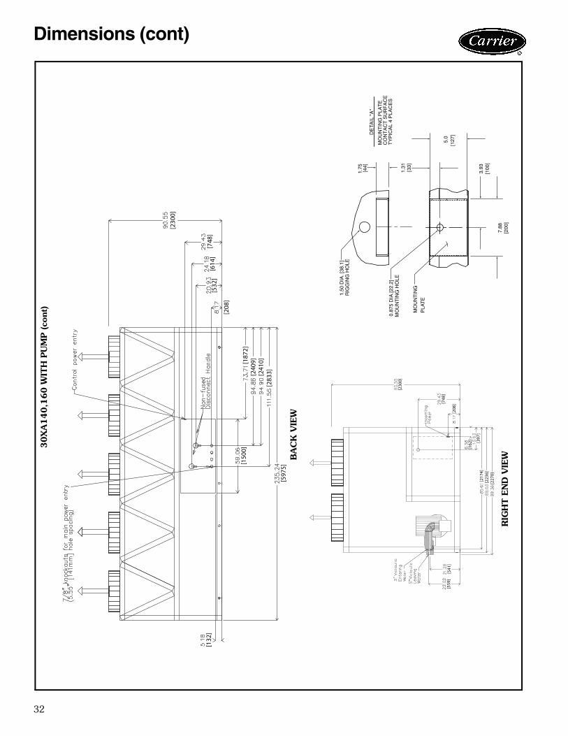
32
[559
][5
41]
[217
4][2
236]
[227
0]
[162
] [397
]
[208
][748
]
[230
0]
a30-4407
30X
A140,1
60 W
ITH
PU
MP (co
nt)
3.93
7.88
[200
]
DE
TAIL
"A
"
MO
UN
TIN
G P
LAT
EC
ON
TA
CT
SU
RF
AC
ET
YP
ICA
L 4
PLA
CE
S
[100
]
MO
UN
TIN
G H
OLE
0.87
5 D
IA.[2
2.2]
MO
UN
TIN
G
PLA
TE
1.50
DIA
. [38
.1]
RIG
GIN
G H
OLE
[127
]5.
0
[33]
1.31
1.75 [44]
BA
CK
VIE
W
RIG
HT E
ND
VIE
W
[132
]
[150
0]
[597
5]
[187
2][2
409]
[241
0][2
833]
[230
0]
[748
][6
14]
[532
]
[208
]
Dimensions (cont)
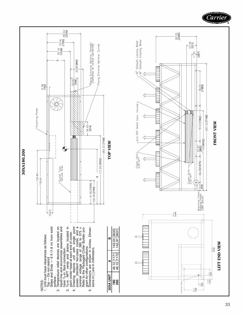
33
[459
][1
475]
[863
][1
982]
[450
2][7
168]
[198
2][2
87]
[571
]
[230
0]
[155
5][2
769]
B[4
502]
[716
8]
[914
]
[508
][8
60]
[162
]
A
[152
8][1
782]
[223
6]
NO
TE
S:
1.U
nit m
ust h
ave
clea
ranc
es a
s fo
llow
s:To
p —
Do
not r
estr
ict
Sid
es a
nd E
nds
— 6
ft
(1.8
m)
from
sol
idsu
rfac
e.2.
Tem
pera
ture
rel
ief
devi
ces
are
loca
ted
onliq
uid
line
and
econ
omiz
er a
ssem
blie
s an
dha
ve 1
/ 4-in
. fla
re c
onne
ctio
n.3.
3 /8-
in.
NP
T
vent
s an
d dr
ains
lo
cate
d in
each
coo
ler
head
at e
ach
end
of c
oole
r.4.
Dra
win
g de
pict
s un
it w
ith
sing
le
poin
tpo
wer
, st
anda
rd
two-
pass
co
oler
, an
d a
nom
inal
vol
tage
ran
ge o
f 38
0 to
575
v.
Ref
er t
o th
e P
acka
ged
Chi
ller
Bui
lder
pro
-gr
am fo
r ot
her
conf
igur
atio
ns.
5.D
imen
sion
s ar
e sh
own
in i
nche
s. D
imen
-si
ons
in [
] are
in m
illim
eter
s.
30X
A U
NIT
AB
180
46.1
2 [1
171]
143.
04 [3
633]
200
46.1
5 [1
172]
142.
97 [3
631]
a30-4408
30X
A180,2
00
TO
P V
IEW FR
ON
T V
IEW
LEFT
EN
D V
IEW
[230
0]
[223
6]
[748
]
[208
] [162
][3
97]
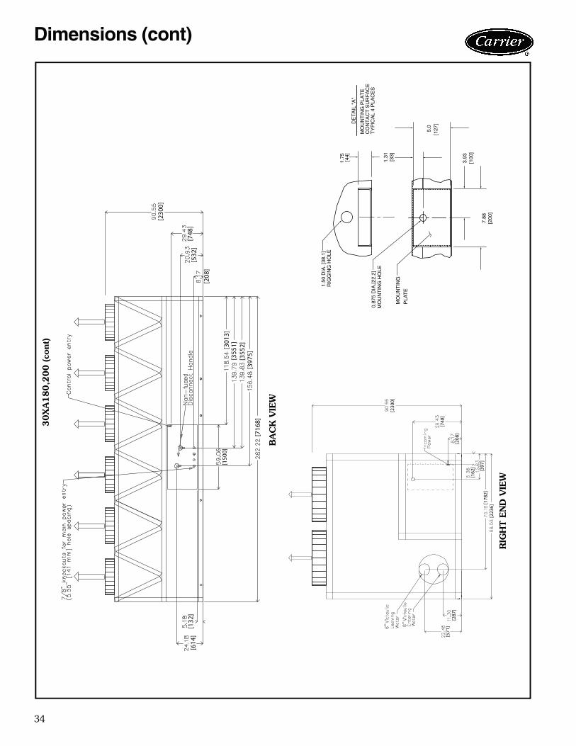
34
[230
0]
[748
]
[208
]
[162
]
[397
][1
782]
[223
6]
[287
][5
71]
[230
0]
[748
][5
32]
[208
]
[150
0][3
013]
[355
1][3
552]
[397
5][7
168]
[132
][6
14]
30X
A180,2
00 (co
nt)
a30-4174
3.93
7.88
[200
]
DE
TAIL
"A
"
MO
UN
TIN
G P
LAT
EC
ON
TA
CT
SU
RF
AC
ET
YP
ICA
L 4
PLA
CE
S
[100
]
MO
UN
TIN
G H
OLE
0.87
5 D
IA.[2
2.2]
MO
UN
TIN
G
PLA
TE
1.50
DIA
. [38
.1]
RIG
GIN
G H
OLE
[127
]5.
0
[33]
1.31
1.75 [44]
BA
CK
VIE
W
RIG
HT E
ND
VIE
W
Dimensions (cont)
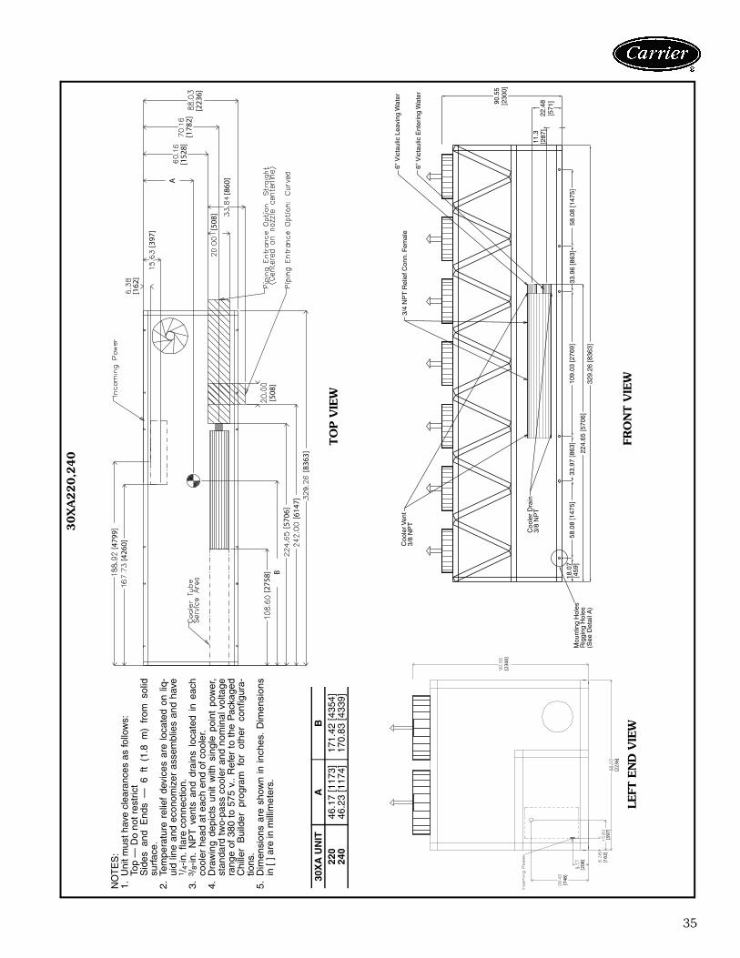
35
3/4
NP
T R
elie
f Con
n. F
emal
e
6" V
icta
ulic
Ent
erin
g W
ater
6" V
icta
ulic
Lea
ving
Wat
erC
oole
r Ven
t3/
8 N
PT
Coo
ler
Dra
in3/
8 N
PT
Mou
ntin
g H
oles
Rig
ging
Hol
es(S
ee D
etai
l A)
90.5
5[2
300]
22.4
8[5
71]
11.3
[287
]
329.
26 [8
363]
224.
65 [5
706]
109.
03 [2
769]
58.0
8 [1
475]
58.0
8 [1
475]
33.9
7 [8
63]
33.9
6 [8
63]
18.0
7[4
59]
[162
]
[397
]
A
[152
8][1
782]
[223
6]
[508
]
[860
]
[508
]
[479
9][4
260]
[836
3][6
147]
[570
6]B
[275
8]
NO
TE
S:
1.U
nit m
ust h
ave
clea
ranc
es a
s fo
llow
s:To
p —
Do
not r
estr
ict
Sid
es a
nd E
nds
— 6
ft
(1.8
m)
from
sol
idsu
rfac
e.2.
Tem
pera
ture
rel
ief
devi
ces
are
loca
ted
on l
iq-
uid
line
and
econ
omiz
er a
ssem
blie
s an
d ha
ve1 /
4-in
. fla
re c
onne
ctio
n.3.
3 /8-
in.
NP
T v
ents
and
dra
ins
loca
ted
in e
ach
cool
er h
ead
at e
ach
end
of c
oole
r.4.
Dra
win
g de
pict
s un
it w
ith s
ingl
e po
int
pow
er,
stan
dard
two-
pass
coo
ler
and
nom
inal
vol
tage
rang
e of
380
to
575
v..
Ref
er t
o th
e P
acka
ged
Chi
ller
Bui
lder
pr
ogra
m
for
othe
r co
nfig
ura-
tions
.5.
Dim
ensi
ons
are
show
n in
inch
es.
Dim
ensi
ons
in [
] are
in m
illim
eter
s.
30X
A U
NIT
AB
220
46.1
7 [1
173]
171.
42 [4
354]
240
46.2
3 [1
174]
170.
83 [4
339]
a30-4409
30X
A220,2
40
TO
P V
IEW
LEFT
EN
D V
IEW
FRO
NT V
IEW
[230
0]
[223
6]
[748
]
[208
] [162
][3
97]
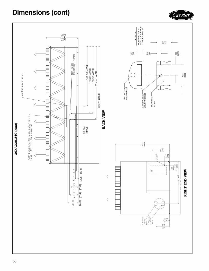
36
[150
0]
[748
][6
14]
[532
][2
08]
[132
]
[230
0]
[426
0][4
798]
[479
9][5
221]
[836
3]
a30-4176
30X
A220,2
40 (co
nt)
3.93
7.88
[200
]
DE
TAIL
"A
"
MO
UN
TIN
G P
LAT
EC
ON
TA
CT
SU
RF
AC
ET
YP
ICA
L 4
PLA
CE
S
[100
]
MO
UN
TIN
G H
OLE
0.87
5 D
IA.[2
2.2]
MO
UN
TIN
G
PLA
TE
1.50
DIA
. [38
.1]
RIG
GIN
G H
OLE
[127
]5.
0
[33]
1.31
1.75 [44]
BA
CK
VIE
W
RIG
HT E
ND
VIE
W
[230
0]
[748
]
[208
]
[162
]
[397
][1
782]
[223
6]
[287
][5
71]
Dimensions (cont)
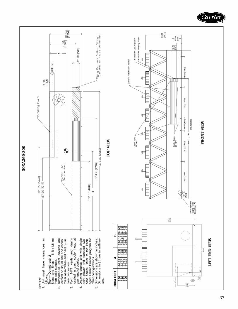
37
3/4
NP
T R
elie
f Con
n. F
emal
e 8" V
icta
ulic
Ent
erin
g W
ater
8" V
icta
ulic
Lea
ving
Wat
erC
oole
r Ven
t3/
8 N
PT
Coo
ler
Dra
in3/
8 N
PT
Mou
ntin
g H
oles
Rig
ging
Hol
es(S
ee D
etai
l A)
90.5
5[2
300]
23.6
3[6
00]
12.2
1[3
10]
376.
2 [9
555]
304.
71 [7
740]
78.0
2 [1
982]
78.0
2 [1
982]
78.0
2 [1
982]
78.0
2 [1
982]
31.9
6 [8
12]
16.1
[409
]
[162
]
[317
]
A
[180
5][2
236]
[508
]
[955
5][7
740]
B[478
4]
[501
1][574
7]N
OT
ES
:1.
Uni
t m
ust
have
cl
eara
nces
as
follo
ws:
Top
— D
o no
t res
tric
tS
ides
and
End
s —
6 f
t (1
.8 m
)fr
om s
olid
sur
face
.2.
Tem
pera
ture
re
lief
devi
ces
are
loca
ted
on l
iqui
d lin
e an
d ec
ono-
miz
er a
ssem
blie
s an
d ha
ve 1
/ 4-in
.fla
re c
onne
ctio
n.3.
3 /8-
in.
NP
T
vent
s an
d dr
ains
loca
ted
in e
ach
cool
er h
ead
atea
ch e
nd o
f coo
ler.
4.D
raw
ing
depi
cts
unit
with
sin
gle
poin
t po
wer
an
d st
anda
rd
two-
pass
coo
ler.
Ref
er t
o th
e P
ack-
aged
Chi
ller
Bui
lder
pro
gram
for
othe
r co
nfig
urat
ions
.5.
Dim
ensi
ons
are
show
n in
inch
es.
Dim
ensi
ons
in [
] a
re i
n m
illim
e-te
rs.
30X
A U
NIT
AB
260
44.2
2 [1
123]
216.
16 [5
490]
280
44.3
0 [1
125]
215.
86 [5
483]
300
44.3
2 [1
126]
216.
18 [5
491]
30X
A260-3
00
TO
P V
IEW
LEFT
EN
D V
IEW
FRO
NT V
IEW
[230
0]
[223
6]
[748
]
[208
] [162
][3
97]
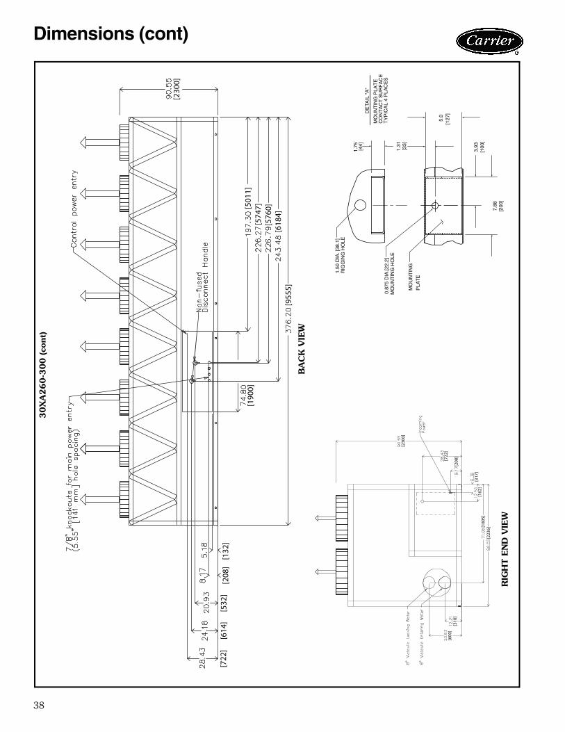
38
[722
][6
14]
[532
][2
08]
[132
]
[190
0]
[955
5][6
184]
[576
0][5
747][5
011]
[230
0]
[230
0]
[722
]
[208
]
[317
][1
62]
[180
5][2
236]
[600
][3
10]
a30-4178
30X
A260-3
00 (co
nt)
3.93
7.88
[200
]
DE
TAIL
"A
"
MO
UN
TIN
G P
LAT
EC
ON
TA
CT
SU
RF
AC
ET
YP
ICA
L 4
PLA
CE
S
[100
]
MO
UN
TIN
G H
OLE
0.87
5 D
IA.[2
2.2]
MO
UN
TIN
G
PLA
TE
1.50
DIA
. [38
.1]
RIG
GIN
G H
OLE
[127
]5.
0
[33]
1.31
1.75 [44]
BA
CK
VIE
W
RIG
HT E
ND
VIE
W
Dimensions (cont)
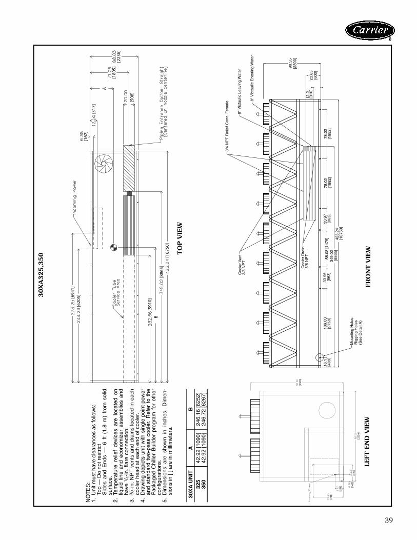
39
3/4
NP
T R
elie
f Con
n. F
emal
e 8" V
icta
ulic
Ent
erin
g W
ater
8" V
icta
ulic
Lea
ving
Wat
erC
oole
r Ven
t3/
8 N
PT
Coo
ler
Dra
in3/
8 N
PT
Mou
ntin
g H
oles
Rig
ging
Hol
es(S
ee D
etai
l A)
90.5
5[2
300]
23.6
3[6
00]
12.2
1[3
10]
423.
24
[107
50]
349.
02
[886
5]
109.
03[2
769]
78.0
2[1
982]
78.0
2[1
982]
58.0
8 [1
475]
33.9
7[8
63]
33.9
6 [8
63]
16.1
[4
09]
FR
ON
T V
IEW
[162
]
[317
]
A
[180
5][2
236]
[508
]
[107
50]
[886
5]B
[591
0]
[620
5][694
1]
NO
TE
S:
1.U
nit m
ust h
ave
clea
ranc
es a
s fo
llow
s:To
p —
Do
not r
estr
ict
Sid
es a
nd E
nds
— 6
ft
(1.8
m)
from
sol
idsu
rfac
e.2.
Tem
pera
ture
rel
ief
devi
ces
are
loca
ted
onliq
uid
line
and
econ
omiz
er a
ssem
blie
s an
dha
ve 1
/ 4-in
. fla
re c
onne
ctio
n.3.
3 /8-
in.
NP
T v
ents
and
dra
ins
loca
ted
in e
ach
cool
er h
ead
at e
ach
end
of c
oole
r.4.
Dra
win
g de
pict
s un
it w
ith s
ingl
e po
int
pow
eran
d st
anda
rd t
wo-
pass
coo
ler.
Ref
er t
o th
eP
acka
ged
Chi
ller
Bui
lder
pro
gram
for
oth
erco
nfig
urat
ions
.5.
Dim
ensi
ons
are
show
n in
inc
hes.
Dim
en-
sion
s in
[ ] a
re in
mill
imet
ers.
30X
A U
NIT
AB
325
42.9
2 [1
090]
246.
16 [6
252]
350
42.9
2 [1
090]
246.
72 [6
267]
a30-4410
30X
A325,3
50 T
OP V
IEW
FRO
NT V
IEW
LEFT
EN
D V
IEW
[230
0]
[223
6]
[748
]
[208
] [162
][3
97]
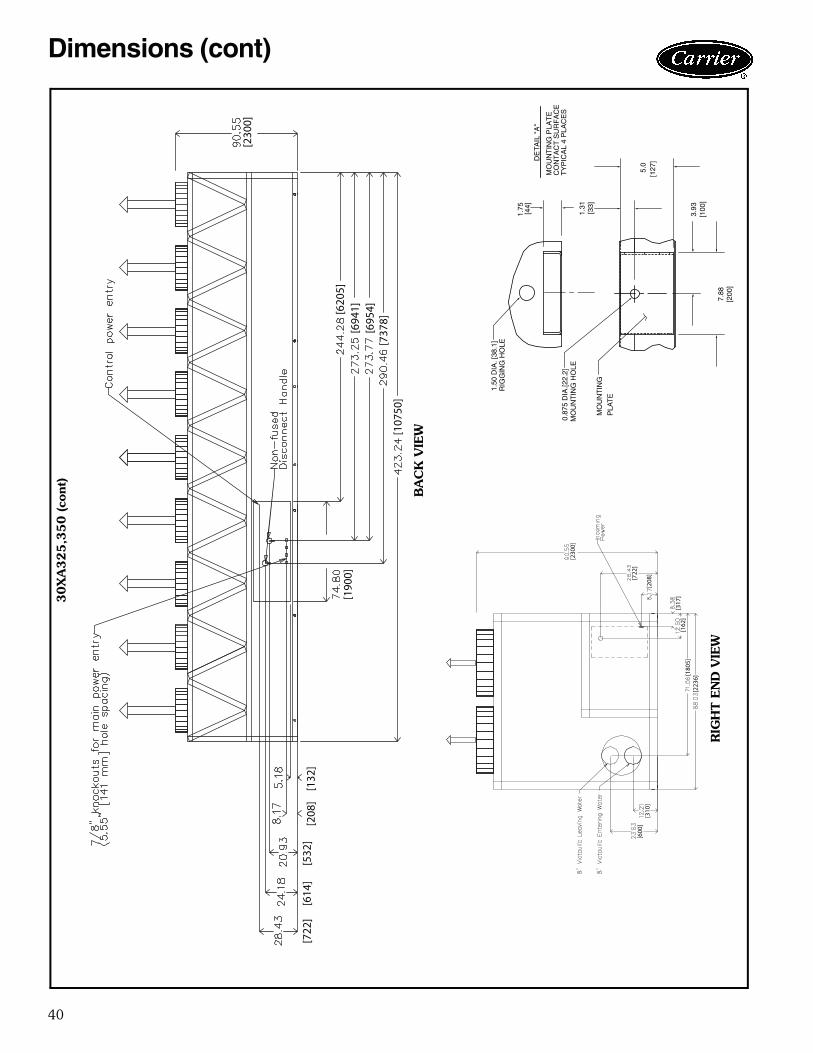
40
[230
0]
[620
5][6
941]
[695
4][7
378]
[107
50]
[190
0]
[722
][6
14]
[532
][2
08]
[132
]
a30-4180
30X
A325,3
50 (co
nt)
3.93
7.88
[200
]
DE
TAIL
"A
"
MO
UN
TIN
G P
LAT
EC
ON
TA
CT
SU
RF
AC
ET
YP
ICA
L 4
PLA
CE
S
[100
]
MO
UN
TIN
G H
OLE
0.87
5 D
IA.[2
2.2]
MO
UN
TIN
G
PLA
TE
1.50
DIA
. [38
.1]
RIG
GIN
G H
OLE
[127
]5.
0
[33]
1.31
1.75 [44]
BA
CK
VIE
W
RIG
HT E
ND
VIE
W
[230
0]
[722
]
[208
]
[317
][1
62]
[180
5][2
236]
[600
][3
10]
Dimensions (cont)
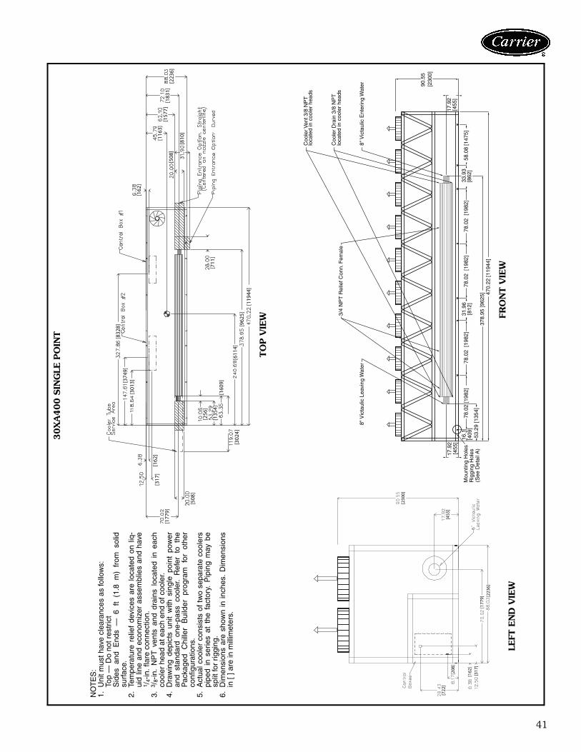
41
[230
0]
[455
]
[177
9][2
236]
[162
][3
17]
[208
]
[722
]
3/4
NP
T R
elie
f Con
n. F
emal
e
8" V
icta
ulic
Ent
erin
g W
ater
8" V
icta
ulic
Lea
ving
Wat
er
Coo
ler V
ent 3
/8 N
PT
loca
ted
in c
oole
r he
ads
Coo
ler
Dra
in 3
/8 N
PT
loca
ted
in c
oole
r he
ads
Mou
ntin
g H
oles
Rig
ging
Hol
es(S
ee D
etai
l A)
90.5
5[2
300]
17.9
2[4
55]
17.9
2[4
55]
470.
22 [1
1944
]37
8.95
[962
5]53
.29
[135
4]
78.0
2 [1
982]
78.0
2 [1
982]
78.0
2 [1
982]
78.0
2 [1
982]
58.0
8 [1
475]
33.9
3[8
62]
31.9
6[8
12]
16.1
[4
09]
[162
]
[508
]
[810
]
[116
3][1
577]
[183
1][2
236]
[711
]
[119
44]
[962
5][6
114]
[302
4]
[508
]
[177
9]
[317
][1
62]
[256
]
[135
4][1
609]
[301
3][374
9][8
328]
NO
TE
S:
1.U
nit m
ust h
ave
clea
ranc
es a
s fo
llow
s:To
p —
Do
not r
estr
ict
Sid
es a
nd E
nds
— 6
ft
(1.8
m)
from
sol
idsu
rfac
e.2.
Tem
pera
ture
rel
ief
devi
ces
are
loca
ted
on l
iq-
uid
line
and
econ
omiz
er a
ssem
blie
s an
d ha
ve1 /
4-in
. fla
re c
onne
ctio
n.3.
3 /8-
in.
NP
T v
ents
and
dra
ins
loca
ted
in e
ach
cool
er h
ead
at e
ach
end
of c
oole
r.4.
Dra
win
g de
pict
s un
it w
ith s
ingl
e po
int
pow
eran
d st
anda
rd o
ne-p
ass
cool
er.
Ref
er t
o th
eP
acka
ged
Chi
ller
Bui
lder
pr
ogra
m
for
othe
rco
nfig
urat
ions
.5.
Act
ual c
oole
r co
nsis
ts o
f tw
o se
para
te c
oole
rspi
ped
in s
erie
s at
the
fac
tory
. P
ipin
g m
ay b
esp
lit fo
r rig
ging
.6.
Dim
ensi
ons
are
show
n in
inch
es.
Dim
ensi
ons
in [
] are
in m
illim
eter
s.
a30-4181
30X
A400 S
ING
LE P
OIN
T
TO
P V
IEW
LEFT
EN
D V
IEW
FRO
NT V
IEW
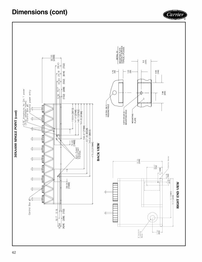
42
[230
0]
[722
]
[208
]
[162
][3
17]
[183
1][2
236]
[455
]
[230
0]
[132
][2
08]
[532
][6
14]
[722
]
[301
3][3
749]
[376
3][4
186]
[190
0]
[778
9][8
328]
[865
3][1
1944
]
[150
0]
[424
][2
08]
[132
]
a30-4182
30X
A400 S
ING
LE P
OIN
T (co
nt)
BA
CK
VIE
W
RIG
HT E
ND
VIE
W
3.93
7.88
[200
]
DE
TAIL
"A
"
MO
UN
TIN
G P
LAT
EC
ON
TA
CT
SU
RF
AC
ET
YP
ICA
L 4
PLA
CE
S
[100
]
MO
UN
TIN
G H
OLE
0.87
5 D
IA.[2
2.2]
MO
UN
TIN
G
PLA
TE
1.50
DIA
. [38
.1]
RIG
GIN
G H
OLE
[127
]5.
0
[33]
1.31
1.75 [44]
Dimensions (cont)
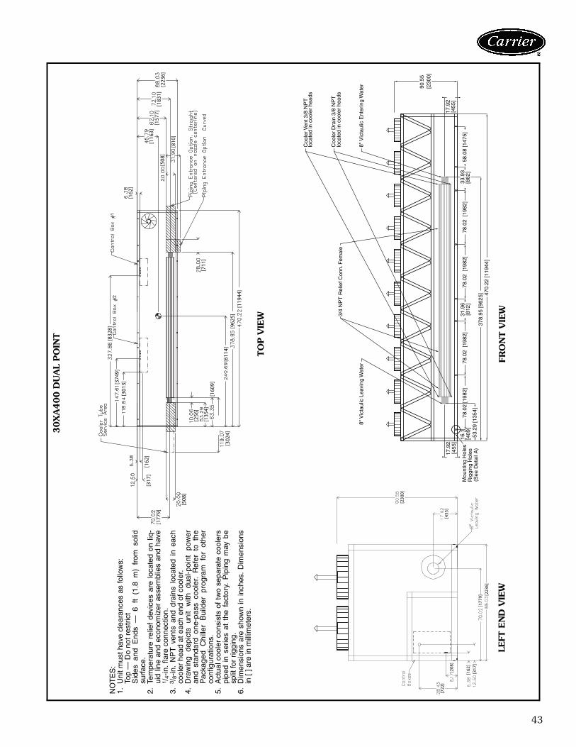
43
NO
TE
S:
1.U
nit m
ust h
ave
clea
ranc
es a
s fo
llow
s:To
p —
Do
not r
estr
ict
Sid
es a
nd E
nds
— 6
ft
(1.8
m)
from
sol
idsu
rfac
e.2.
Tem
pera
ture
rel
ief
devi
ces
are
loca
ted
on l
iq-
uid
line
and
econ
omiz
er a
ssem
blie
s an
d ha
ve1 /
4-in
. fla
re c
onne
ctio
n.3.
3 /8-
in.
NP
T v
ents
and
dra
ins
loca
ted
in e
ach
cool
er h
ead
at e
ach
end
of c
oole
r.4.
Dra
win
g de
pict
s un
it w
ith
dual
-poi
nt
pow
eran
d st
anda
rd o
ne-p
ass
cool
er.
Ref
er t
o th
eP
acka
ged
Chi
ller
Bui
lder
pr
ogra
m
for
othe
rco
nfig
urat
ions
.5.
Act
ual c
oole
r co
nsis
ts o
f tw
o se
para
te c
oole
rspi
ped
in s
erie
s at
the
fac
tory
. P
ipin
g m
ay b
esp
lit fo
r rig
ging
.6.
Dim
ensi
ons
are
show
n in
inch
es.
Dim
ensi
ons
in [
] are
in m
illim
eter
s.
30X
A400 D
UA
L PO
INT
TO
P V
IEW
LEFT
EN
D V
IEW
FRO
NT V
IEW
[230
0]
[455
]
[177
9][2
236]
[162
][3
17]
[208
]
[722
]
3/4
NP
T R
elie
f Con
n. F
emal
e
8" V
icta
ulic
Ent
erin
g W
ater
8" V
icta
ulic
Lea
ving
Wat
er
Coo
ler V
ent 3
/8 N
PT
loca
ted
in c
oole
r he
ads
Coo
ler
Dra
in 3
/8 N
PT
loca
ted
in c
oole
r he
ads
Mou
ntin
g H
oles
Rig
ging
Hol
es(S
ee D
etai
l A)
90.5
5[2
300]
17.9
2[4
55]
17.9
2[4
55]
470.
22 [1
1944
]37
8.95
[962
5]53
.29
[135
4]
78.0
2 [1
982]
78.0
2 [1
982]
78.0
2 [1
982]
78.0
2 [1
982]
58.0
8 [1
475]
33.9
3[8
62]
31.9
6[8
12]
16.1
[4
09]
[162
]
[508
]
[810
]
[116
3][1
577]
[183
1][2
236]
[711
]
[119
44]
[962
5][6
114]
[302
4]
[508
]
[177
9]
[317
][1
62]
[256
]
[135
4][1
609]
[301
3][374
9][8
328]
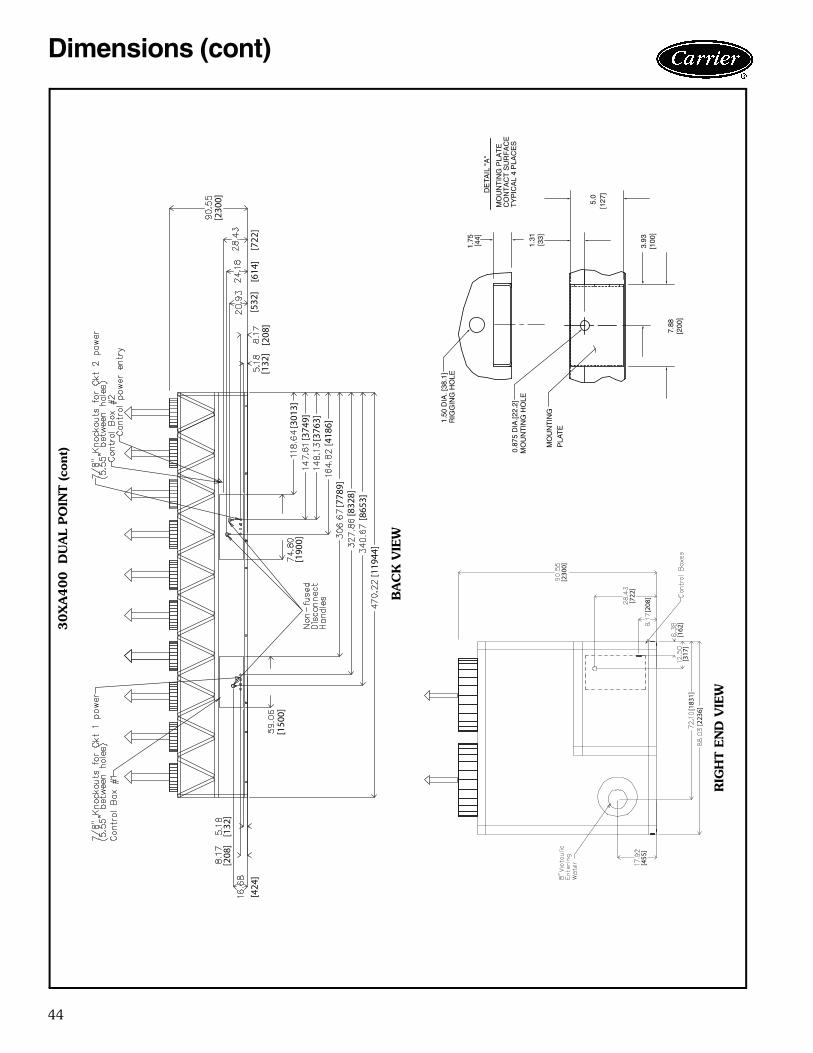
44
[150
0]
[190
0]
[119
44]
[865
3][8
328]
[778
9][4
186]
[376
3][3
749]
[301
3]
[132
][2
08]
[532
][6
14]
[722
]
[230
0]
[424
]
[208
][1
32]
a30-4182
30X
A400 D
UA
L PO
INT (co
nt)
BA
CK
VIE
W
RIG
HT E
ND
VIE
W
3.93
7.88
[200
]
DE
TAIL
"A
"
MO
UN
TIN
G P
LAT
EC
ON
TA
CT
SU
RF
AC
ET
YP
ICA
L 4
PLA
CE
S
[100
]
MO
UN
TIN
G H
OLE
0.87
5 D
IA.[2
2.2]
MO
UN
TIN
G
PLA
TE
1.50
DIA
. [38
.1]
RIG
GIN
G H
OLE
[127
]5.
0
[33]
1.31
1.75 [44]
[230
0]
[722
]
[208
]
[162
][3
17]
[183
1][2
236]
[455
]
Dimensions (cont)
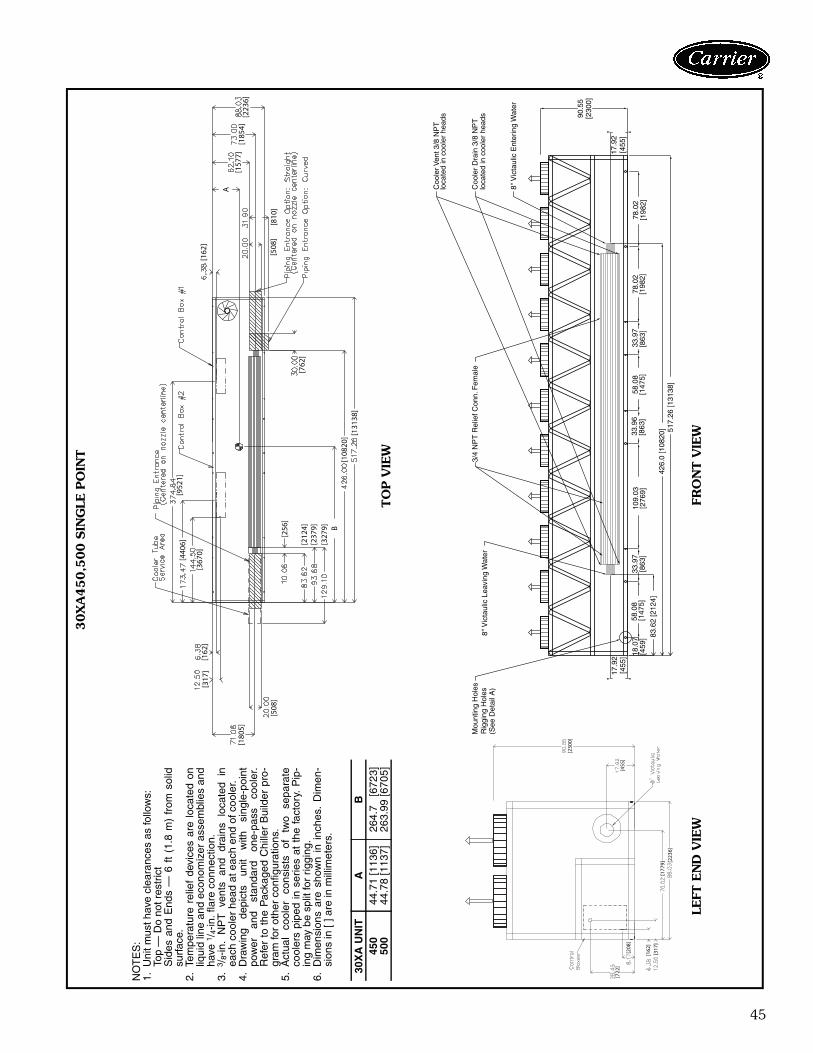
45
3/4
NP
T R
elie
f Con
n. F
emal
e
8" V
icta
ulic
Ent
erin
g W
ater
8" V
icta
ulic
Lea
ving
Wat
er
Coo
ler V
ent 3
/8 N
PT
loca
ted
in c
oole
r he
ads
Coo
ler
Dra
in 3
/8 N
PT
loca
ted
in c
oole
r he
ads
Mou
ntin
g H
oles
R
iggi
ng H
oles
(See
Det
ail A
)
90.5
5[2
300]
17.9
2[4
55]
17.9
2[4
55]
517.
26 [1
3138
]42
6.0
[108
20]
83.6
2 [2
124]
109.
03[2
769]
78.0
2[1
982]
78.0
2[1
982]
58.0
8[1
475]
58.0
8[1
475]
33.9
7[8
63]
33.9
7[8
63]
33.9
6[8
63]
18.0
7[4
59]
[162
]
[508
][8
10]
A
[157
7][1
854]
[223
6]
[762
]
[131
38]
[108
20]
B
[256
]
[212
4][2
379]
[327
9]
[508
]
[180
5]
[317
][1
62]
[952
1]
[367
0]
[440
6]
NO
TE
S:
1.U
nit m
ust h
ave
clea
ranc
es a
s fo
llow
s:To
p —
Do
not r
estr
ict
Sid
es a
nd E
nds
— 6
ft
(1.8
m)
from
sol
idsu
rfac
e.2.
Tem
pera
ture
rel
ief
devi
ces
are
loca
ted
onliq
uid
line
and
econ
omiz
er a
ssem
blie
s an
dha
ve 1
/ 4-in
. fla
re c
onne
ctio
n.3.
3 /8-
in.
NP
T
vent
s an
d dr
ains
lo
cate
d in
each
coo
ler
head
at e
ach
end
of c
oole
r.4.
Dra
win
g de
pict
s un
it w
ith
sing
le-p
oint
pow
er
and
stan
dard
on
e-pa
ss
cool
er.
Ref
er t
o th
e P
acka
ged
Chi
ller
Bui
lder
pro
-gr
am fo
r ot
her
conf
igur
atio
ns.
5.A
ctua
l co
oler
co
nsis
ts
of
two
sepa
rate
cool
ers
pipe
d in
ser
ies
at t
he f
acto
ry.
Pip
-in
g m
ay b
e sp
lit fo
r rig
ging
.6.
Dim
ensi
ons
are
show
n in
inc
hes.
Dim
en-
sion
s in
[ ] a
re in
mill
imet
ers.
30X
A U
NIT
AB
450
44.7
1 [1
136]
264.
7 [6
723]
500
44.7
8 [1
137]
263.
99 [6
705]
a30-4183
30X
A450,5
00 S
ING
LE P
OIN
T
TO
P V
IEW
FRO
NT V
IEW
LEFT
EN
D V
IEW
[230
0]
[455
]
[177
9][2
236]
[162
][3
17]
[208
]
[722
]
46
[230
0]
[722
][6
14]
[532
][1
32]
[208
]
[190
0][3
670]
[440
6][4
419]
[484
3][8
983]
[952
1][9
846]
[131
38]
[150
0]
[424
]
[208
][1
32]
a30-4184
→ 3
0X
A450,5
00 S
ING
LE P
OIN
T (co
nt)
BA
CK
VIE
W
RIG
HT E
ND
VIE
W
3.93
7.88
[200
]
DE
TAIL
"A
"
MO
UN
TIN
G P
LAT
EC
ON
TA
CT
SU
RF
AC
ET
YP
ICA
L 4
PLA
CE
S
[100
]
MO
UN
TIN
G H
OLE
0.87
5 D
IA.[2
2.2]
MO
UN
TIN
G
PLA
TE
1.50
DIA
. [38
.1]
RIG
GIN
G H
OLE
[127
]5.
0
[33]
1.31
1.75 [44]
[230
0]
[722
]
[208
]
[162
][3
17]
[183
1][2
236]
[455
]
Dimensions (cont)
809
47
NO
TE
S:
1.U
nit m
ust h
ave
clea
ranc
es a
s fo
llow
s:To
p —
Do
not r
estr
ict
Sid
es a
nd E
nds
— 6
ft
(1.8
m)
from
sol
idsu
rfac
e.2.
Tem
pera
ture
rel
ief
devi
ces
are
loca
ted
onliq
uid
line
and
econ
omiz
er a
ssem
blie
s an
dha
ve 1
/ 4-in
. fla
re c
onne
ctio
n.3.
3 /8-
in.
NP
T
vent
s an
d dr
ains
lo
cate
d in
each
coo
ler
head
at e
ach
end
of c
oole
r.4.
Dra
win
g de
pict
s un
it w
ith d
ual-p
oint
pow
eran
d st
anda
rd o
ne-p
ass
cool
er.
Ref
er t
oth
e P
acka
ged
Chi
ller
Bui
lder
pro
gram
for
othe
r co
nfig
urat
ions
.5.
Act
ual
cool
er
cons
ists
of
tw
o se
para
teco
oler
s pi
ped
in s
erie
s at
the
fac
tory
. P
ip-
ing
may
be
split
for
riggi
ng.
6.D
imen
sion
s ar
e sh
own
in i
nche
s. D
imen
-si
ons
in [
] are
in m
illim
eter
s.
30X
A U
NIT
AB
450
44.7
1 [1
136]
264.
7 [6
723]
500
44.7
8 [1
137]
263.
99 [6
705]
a30-4183
30X
A450,5
00 D
UA
L PO
INT 3/
4 N
PT
Rel
ief C
onn.
Fem
ale
8" V
icta
ulic
Ent
erin
g W
ater
8" V
icta
ulic
Lea
ving
Wat
er
Coo
ler V
ent 3
/8 N
PT
loca
ted
in c
oole
r he
ads
Coo
ler
Dra
in 3
/8 N
PT
loca
ted
in c
oole
r he
ads
Mou
ntin
g H
oles
R
iggi
ng H
oles
(See
Det
ail A
)
90.5
5[2
300]
17.9
2[4
55]
17.9
2[4
55]
517.
26 [1
3138
]42
6.0
[108
20]
83.6
2 [2
124]
109.
03[2
769]
78.0
2[1
982]
78.0
2[1
982]
58.0
8[1
475]
58.0
8[1
475]
33.9
7[8
63]
33.9
7[8
63]
33.9
6[8
63]
18.0
7[4
59]
TO
P V
IEW
FRO
NT V
IEW
LEFT
EN
D V
IEW
[230
0]
[455
]
[177
9][2
236]
[162
][3
17]
[208
]
[722
]
[162
]
[508
][8
10]
A
[157
7][1
854]
[223
6]
[762
]
[131
38]
[108
20]
B
[256
]
[212
4][2
379]
[327
9]
[508
]
[180
5]
[317
][1
62]
[952
1]
[367
0]
[440
6]
48
[230
0]
[722
][6
14]
[532
][1
32]
[208
]
[190
0][3
670]
[440
6][4
419]
[484
3][8
983]
[952
1][9
846]
[131
38]
[150
0]
[424
]
[208
][1
32]
a30-4184
30X
A450,5
00 D
UA
L PO
INT (co
nt)
BA
CK
VIE
W
RIG
HT E
ND
VIE
W
3.93
7.88
[200
]
DE
TAIL
"A
"
MO
UN
TIN
G P
LAT
EC
ON
TA
CT
SU
RF
AC
ET
YP
ICA
L 4
PLA
CE
S
[100
]
MO
UN
TIN
G H
OLE
0.87
5 D
IA.[2
2.2]
MO
UN
TIN
G
PLA
TE
1.50
DIA
. [38
.1]
RIG
GIN
G H
OLE
[127
]5.
0
[33]
1.31
1.75 [44]
[230
0]
[722
]
[208
]
[162
][3
17]
[183
1][2
236]
[455
]
Dimensions (cont)
49
EN
GLI
SH
SI
*30X
A40
0-50
0 un
its a
re e
quip
ped
with
sta
ndar
d co
oler
s on
ly. R
efer
to u
nit d
imen
sion
al d
raw
ings
for
cool
er d
imen
sion
s.N
OT
E: R
efer
to d
imen
sion
al d
raw
ings
for
all o
ther
uni
t dim
ensi
ons.
30X
AU
NIT
SIZ
E*
STA
ND
AR
D C
OO
LE
RP
LU
S O
NE
PA
SS
CO
OL
ER
MIN
US
ON
E P
AS
S C
OO
LE
R
Dis
tan
ce t
oL
eavi
ng
W
ater
Co
nn
ecti
on
(in
.)
Hei
gh
tL
eavi
ng
W
ater
Co
nn
ecti
on
(in
.)
Dis
tan
ce t
oL
eavi
ng
/E
nte
rin
g
Wat
erC
on
nec
tio
n (
in.)
Dis
tan
ce t
oE
nte
rin
g
Wat
erC
on
nec
tio
n(i
n.)
Hei
gh
tE
nte
rin
g
Wat
erC
on
nec
tio
n(i
n.)
Vic
tau
licC
on
nec
tio
nS
ize
(in
.)
Dis
tan
ce t
oL
eavi
ng
W
ater
Co
nn
ecti
on
(in
.)
Hei
gh
tL
eavi
ng
W
ater
Co
nn
ecti
on
(in
.)
Dis
tan
ce t
oL
eavi
ng
/E
nte
rin
g
Wat
erC
on
nec
tio
n(i
n.)
Dis
tan
ceto
En
teri
ng
W
ater
Co
nn
ecti
on
(in
.)
Hei
gh
tE
nte
rin
g
Wat
erC
on
nec
tio
n(i
n.)
Vic
tau
licC
on
nec
tio
nS
ize
(in
.)
Dis
tan
ce t
oL
eavi
ng
W
ater
Co
nn
ecti
on
(in
.)
Hei
gh
tL
eavi
ng
W
ater
Co
nn
ecti
on
(in
.)
Dis
tan
ce t
oL
eavi
ng
/E
nte
rin
gW
ater
Co
nn
ecti
on
(in
.)
Dis
tan
ce t
oE
nte
rin
gW
ater
Co
nn
ecti
on
(in
.)
Hei
gh
tE
nte
rin
g
Wat
erC
on
nec
tio
n(i
n.)
Vic
tau
licC
on
nec
tio
nS
ize
(in
.)
080
121.
219
.168
.112
1.2
10.8
5.0
1.5
19.6
68.1
121.
210
.34.
0–2
.214
.968
.112
4.8
14.9
5.0
090
120.
919
.168
.112
0.9
10.8
5.0
1.2
19.6
68.1
120.
910
.34.
0–2
.514
.968
.112
4.5
14.9
5.0
100
120.
919
.168
.112
0.9
10.8
5.0
1.2
19.6
68.1
120.
910
.34.
0–2
.514
.968
.112
4.5
14.9
5.0
110
120.
919
.168
.112
0.9
10.8
5.0
1.2
19.6
68.1
120.
910
.34.
0–2
.514
.968
.112
4.5
14.9
5.0
120
120.
919
.168
.112
0.9
10.8
5.0
1.2
19.6
68.1
120.
910
.34.
0–2
.514
.968
.112
4.5
14.9
5.0
140
121.
521
.369
.112
1.5
10.6
5.0
1.2
21.3
69.1
121.
510
.65.
0–2
.215
.969
.112
4.8
15.9
6.0
160
121.
521
.369
.112
1.5
10.6
5.0
1.2
21.3
69.1
121.
510
.65.
0–2
.215
.969
.112
4.8
15.9
6.0
180
177.
722
.570
.217
7.7
11.3
6.0
53.6
22.4
70.2
180.
611
.46.
053
.613
.270
.218
0.6
13.2
8.0
200
177.
322
.570
.217
7.3
11.3
6.0
53.2
22.4
70.2
180.
211
.46.
053
.213
.270
.218
0.2
13.2
8.0
220
224.
722
.570
.222
4.7
11.3
6.0
100.
622
.470
.222
7.6
11.4
6.0
100.
613
.270
.222
7.6
13.2
8.0
240
224.
722
.570
.222
4.7
11.3
6.0
100.
622
.470
.222
7.6
11.4
6.0
100.
613
.270
.222
7.6
13.2
8.0
260
304.
723
.671
.130
4.7
12.2
8.0
180.
323
.471
.131
0.3
12.5
8.0
180.
316
.371
.131
0.3
16.3
8.0
280
304.
723
.671
.130
4.7
12.2
8.0
180.
323
.471
.131
0.3
12.5
8.0
180.
316
.371
.131
0.3
16.3
8.0
300
304.
723
.671
.130
4.7
12.2
8.0
180.
323
.471
.131
0.3
12.5
8.0
180.
316
.371
.131
0.3
16.3
8.0
325
349.
023
.671
.134
9.0
12.2
8.0
224.
723
.471
.135
4.7
12.5
8.0
224.
716
.371
.135
4.7
16.3
8.0
350
349.
023
.671
.134
9.0
12.2
8.0
224.
723
.471
.135
4.7
12.5
8.0
224.
716
.371
.135
4.7
16.3
8.0
30X
AU
NIT
SIZ
E*
STA
ND
AR
D C
OO
LE
RP
LU
S O
NE
PA
SS
CO
OL
ER
MIN
US
ON
E P
AS
S C
OO
LE
R
Dis
tan
ce t
oL
eavi
ng
Wat
erC
on
nec
tio
n
(mm
)
Hei
gh
tL
eavi
ng
Wat
erC
on
nec
tio
n(m
m)
Dis
tan
ce t
oL
eavi
ng
/E
nte
rin
gW
ater
Co
nn
ecti
on
(mm
)
Dis
tan
ce t
oE
nte
rin
gW
ater
Co
nn
ecti
on
(mm
)
Hei
gh
tE
nte
rin
gW
ater
Co
nn
ecti
on
(mm
)
Vic
tau
licC
on
nec
tio
nS
ize
(mm
)
Dis
tan
ce t
oL
eavi
ng
Wat
erC
on
nec
tio
n(m
m)
Hei
gh
tL
eavi
ng
Wat
erC
on
nec
tio
n(m
m)
Dis
tan
ce t
oL
eavi
ng
/E
nte
rin
gW
ater
Co
nn
ecti
on
(mm
)
Dis
tan
ce t
oE
nte
rin
gW
ater
Co
nn
ecti
on
(mm
)
Hei
gh
tE
nte
rin
gW
ater
Co
nn
ecti
on
(mm
)
Vic
tau
licC
on
nec
tio
nS
ize
(mm
)
Dis
tan
ce t
oL
eavi
ng
Wat
erC
on
nec
tio
n(m
m)
Hei
gh
tL
eavi
ng
Wat
erC
on
nec
tio
n(m
m)
Dis
tan
ce t
oL
eavi
ng
/E
nte
rin
gW
ater
Co
nn
ecti
on
(mm
)
Dis
tan
ce t
oE
nte
rin
gW
ater
Co
nn
ecti
on
(m
m)
Hei
gh
tE
nte
rin
gW
ater
Co
nn
ecti
on
(mm
)
Vic
tau
licC
on
nec
tio
nS
ize
(mm
)
080
3077
.848
4.0
1728
.730
77.8
274.
212
7.0
37.9
497.
217
28.7
3077
.826
1.0
101.
6–5
5.1
379.
117
28.7
3170
.737
9.1
127.
009
030
69.6
484.
017
28.7
3069
.627
4.2
127.
029
.749
7.2
1728
.730
69.6
261.
010
1.6
–63.
237
9.1
1728
.731
62.6
379.
112
7.0
100
3069
.648
4.0
1728
.730
69.6
274.
212
7.0
29.7
497.
217
28.7
3069
.626
1.0
101.
6–6
3.2
379.
117
28.7
3162
.637
9.1
127.
011
030
69.6
484.
017
28.7
3069
.627
4.2
127.
029
.749
7.2
1728
.730
69.6
261.
010
1.6
–63.
237
9.1
1728
.731
62.6
379.
112
7.0
120
3069
.648
4.0
1728
.730
69.6
274.
212
7.0
29.7
497.
217
28.7
3069
.626
1.0
101.
6–6
3.2
379.
117
28.7
3162
.637
9.1
127.
014
030
85.8
540.
517
56.2
3085
.826
8.7
127.
030
.154
0.5
1756
.230
85.8
268.
712
7.0
–55.
040
4.6
1756
.231
70.8
404.
615
2.4
160
3085
.854
0.5
1756
.230
85.8
268.
712
7.0
30.1
540.
517
56.2
3085
.826
8.7
127.
0–5
5.0
404.
617
56.2
3170
.840
4.6
152.
418
045
12.3
571.
017
82.1
4512
.328
7.0
152.
413
61.4
569.
517
82.1
4587
.228
8.5
152.
413
61.4
336.
017
82.1
4587
.233
6.0
203.
220
045
02.4
571.
017
82.1
4502
.428
7.0
152.
413
51.6
569.
517
82.1
4577
.428
8.5
152.
413
51.6
336.
017
82.1
4577
.433
6.0
203.
222
057
06.2
571.
017
82.1
5706
.228
7.0
152.
425
55.3
569.
517
82.1
5781
.128
8.5
152.
425
55.3
336.
017
82.1
5781
.133
6.0
203.
224
057
06.2
571.
017
82.1
5706
.228
7.0
152.
425
55.3
569.
517
82.1
5781
.128
8.5
152.
425
55.3
336.
017
82.1
5781
.133
6.0
203.
226
077
39.6
600.
218
04.9
7739
.631
0.1
203.
245
80.8
593.
918
04.9
7882
.831
6.5
203.
245
80.8
413.
318
04.9
7882
.841
3.3
203.
228
077
39.6
600.
218
04.9
7739
.631
0.1
203.
245
80.8
593.
918
04.9
7882
.831
6.5
203.
245
80.8
413.
318
04.9
7882
.841
3.3
203.
230
077
39.6
600.
218
04.9
7739
.631
0.1
203.
245
80.8
593.
918
04.9
7882
.831
6.5
203.
245
80.8
413.
318
04.9
7882
.841
3.3
203.
232
588
65.1
600.
218
04.9
8865
.131
0.1
203.
257
06.4
593.
918
04.9
9008
.431
6.5
203.
257
06.4
413.
318
04.9
9008
.441
3.3
203.
235
088
65.1
600.
218
04.9
8865
.131
0.1
203.
257
06.4
593.
918
04.9
9008
.431
6.5
203.
257
06.4
413.
318
04.9
9008
.441
3.3
203.
2
l io
C
re looC
we iV
edi
S
D
ista
nce
to E
nter
ing
Wat
er C
onne
ctio
n
g nivaeLret a
W
To
p V
iew
Hei
ght L
eavi
ngW
ater
Con
nect
ion
Hei
ght E
nter
ing
Wat
er C
onne
ctio
n
Dis
tanc
e to
Lea
ving
Wat
er C
onne
ctio
n
Dis
tanc
e to
Leav
ing/
Ent
erin
gW
ater
Con
nect
ion
CO
OLE
R O
PTIO
N D
IMEN
SIO
NS
a30-4413
50
Carrier’s Packaged Chiller Builder Selection Program pro-vides quick, easy selection of Carrier’s air-cooled liquidchillers. The program considers specific temperature, fluidand flow requirements among other factors such as foulingand altitude corrections.
Before selecting a chiller, consider the following points:Leaving water temperature (LWT)• If the LWT is less than 40 F (4.4 C), loop freeze protec-
tion to a minimum of 15° F (8.3° C) below the LWT setpoint is required. The medium temperature brine optionis also required.
• If the LWT requirement is greater than 60 F (15.5 C), amixing loop is required.
Entering water temperature (EWT)• If the EWT requirement is greater than 70 F (21.1 C), a
mixing loop is required. The EWT should not exceed70 F (21.1 C) for extended operation. Pulldown can beaccomplished from 95 F (35 C).
Cooler flow rate or cooler delta-T:• The cooler delta-T (EWT – LWT) must fall between
5 and 20° F (2.8 to 11.1° C) while still meeting themaximum entering requirements.
• For larger or smaller delta-T applications, a mixing loopis required.
• If the cooler flow is variable, the rate of change of flowshould not exceed 10% per minute. A loop volume ofgreater than 3 gallons per ton (3.2 l/kW) is alsorecommended.
Cooler pressure drop:• A high cooler pressure drop can be expected when the
cooler delta-T is low. A mixing loop can help to alleviatethis situation.
• Alternatively, consider a reduced pass option whenthere is a low delta-T.
• A low cooler pressure drop can be expected whencooler delta-T is high.
• The plus-one-pass cooler option is recommended toincrease performance when cooler delta-T is high. Thisis particularly helpful with brine applications.
Water quality, fouling factor:• Poor water quality can increase the required cooler foul-
ing factor.• Higher than standard fouling factors lead to lower
capacity and higher input kW from a given chiller sizecompared to running the same application with betterquality water (and lower fouling factors).
Operation below 32 F (0° C) ambient temperature:• Low ambient temperature head pressure control is
required.
• Consider wind baffles if average wind speed is greaterthan 5 mph (8 km/h).
• Consider higher loop volumes, 6 to 10 gallons pernominal ton (6.5 to 10.8 l/kW).
• Loop freeze protection with glycol is strongly recom-mended to a minimum of 15° F (8.3° C) below lowestanticipated ambient temperature.
• Chilled water pump control is strongly recommended;otherwise override capability is required.
Chiller idle below 32 F (0° C) ambient temperature:• Loop freeze protection with glycol is strongly recom-
mended to a minimum of 15° F (8.3° C) below lowestanticipated ambient temperature.
• Chilled water pump control is strongly recommended;otherwise override capability is required.
• Drain the cooler — This will require a small amount ofglycol for residual water. Cooler heaters will need to bedisconnected.
• Consider using a remote cooler. Do not bury refrigerantpiping.
Ambient Temperature:• Highest allowable ambient air temperature is 125 F
(52 C).NOTE: The high ambient option is required for 30XA400-500 chillers which are either operating in multi-chiller con-figurations or have ambient temperatures at or above100 F (37.8 C). Regardless of unit size, it may be neces-sary to select the high ambient option to obtain perfor-mance with ambient air temperatures approaching 125 F(52 C).Cooling capacity requirement:• Do not oversize the chillers by more than 15% at design
conditions.• If capacity control is required below the standard mini-
mum step of unloading, the minimum load controloption should be employed. (See selection program.)
Coil corrosion requirements:• Coastal application• Industrial application• Coastal/industrial application• Urban application• FarmingNOTE: See NACO Packaged Chiller Builder and appropri-ate selection guides for more information.Temperature reset:• Return water (standard)• Outside air temperature (standard)• Space temperature (accessory sensor required)• 4 to 20 mA (requires an energy management module)Demand limit:• 2-step (requires an energy management module)• 4 to 20 mA (requires an energy management module)• CCN Loadshed
Selection procedure
51
To select a 30XA chiller, use the Packaged Chiller BuilderSelection program or follow one of the procedures below.
ENGLISHI Determine 30XA unit size and operating con-
ditions required to meet given capacity atgiven conditions. Given:Capacity . . . . . . . . . . . . . . . . . . . . . . . . . 106 TonsLeaving Chilled Water Temp (LCWT) . . . . . . . .42 FCooler Water Temp Rise . . . . . . . . . . . . . . . . 10° FCondenser Entering Air Temp . . . . . . . . . . . . .95 FFouling Factor (Cooler). . . .0.00010 (ft2 · hr · F/Btu)NOTE: For other than 10° F temperature rise, datacorrections must be made using the Packaged ChillerBuilder Program.
II From Chiller Ratings table on page 56 andpressure drop curves on page 55, determineoperating data for selected unit.Unit . . . . . . . . . . . . . . . . . . . . . . . . . . . .30XA120Capacity . . . . . . . . . . . . . . . . . . . . . . . . 107.5 tonsPower Input . . . . . . . . . . . . . . . . . . . . . .126.7 kWCooler Water Flow . . . . . . . . . . . . . . . . 257.0 gpmCooler Pressure Drop . . . . . . . . . . .12.0 ft of water
SII Determine 30XA unit size and operating con-
ditions required to meet given capacity atgiven conditions. Given:Capacity . . . . . . . . . . . . . . . . . . . . . . . . . . 450 kWLeaving Chilled Water Temp (LCWT) . . . . . . . . 6 CCooler Water Temp Rise . . . . . . . . . . . . . . . 5.6° CCondenser Entering Air Temp . . . . . . . . . . . . 35 CFouling Factor (Cooler). . . . . . . . .0176 (m2 · °C/W)NOTE: For other than 5.6° C temperature rise, datacorrections must be made using the Packaged ChillerBuilder Program.
II From Chiller Ratings table on page 58 andcooler pressure drop curves on page 55,determine operating data for selected unit.Unit . . . . . . . . . . . . . . . . . . . . . . . . . . . .30XA140Capacity . . . . . . . . . . . . . . . . . . . . . . . . .458.1 kWPower Input . . . . . . . . . . . . . . . . . . . . . .147.5 kWCooler Water Flow . . . . . . . . . . . . . . . . . . 19.7 l/sCooler Pressure Drop . . . . . . . . . . . . . . . 41.9 kPa
AquaForce® pump selectionSeveral pump sizes are available for each AquaForce chillersize to provide flexibility in matching water system require-ments. A dual pump option is also available for primary/standby operation. The Carrier Packaged Chiller BuilderSelection Program can be used (and is recommended) forpump selection, or selection can be done manually.
Proper water system design is critical; cooling loads,water pressure drops and proper water line sizing must beaccounted for in order to ensure proper system operation.Incorrect or incomplete analysis/design of the water loopcould lead to low water flow, loss of water temperaturecontrol, and excessive cycling of chiller compressors.
The following are the steps for manual selection of waterpumps for the 30XA chillers (refer to Pump CurveHydronic Package tables).
1. Calculate the water flow rate (gpm or l/s) and thetotal water (or brine) pressure drop of the systemexternal to the 30XA chiller.
2. Use the pump envelope charts (page 52) to deter-mine proper pump sizing. Plot water flow rateand total head, point on the chart. The next pumpcurve above this point corresponds to the correctpump.
NOTE: Although pump bhp (brake horsepower) increaseswith glycol concentration, pumps and pump overloads areselected such that glycol concentrations up to 50% will nottrip pump overloads if run within the recommended gpmranges.Example: Required water flow rate for a 30XA090,chiller is 200 gpm (12.6 l/s). The pressure drop for thewater system external to the chiller is 60 feet (179.4 kPa).The dual pump is needed. Select the pump.
After examining the dual pump charts for the 30XA090and using the indicated flow rate and external pressuredrop, select pump 8.
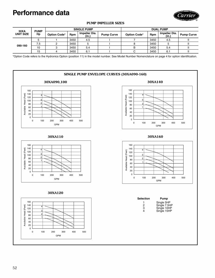
52
PUMP IMPELLER SIZES
*Option Code refers to the Hydronics Option (position 11) in the model number. See Model Number Nomenclature on page 4 for option identification.
30XAUNIT SIZE
PUMPHp
SINGLE PUMP DUAL PUMP
Option Code* Rpm Impeller Dia.(in.) Pump Curve Option Code* Rpm Impeller Dia.
(in.) Pump Curve
090-160
5 1 3450 4.5 I 7 3450 4.5 II7.5 2 3450 5 I 8 3450 5 II10 3 3450 5.4 I B 3450 5.4 II15 4 3450 6.1 I C 3450 6.1 II
0
20
40
60
80
100
120
140
160
0 100 200 300 400 500
GPM
Ava
ilabl
e H
ead
(Fee
t)
1
2
3
4
0
20
40
60
80
100
120
140
160
0 100 200 300 400 500
GPM
Ava
ilabl
e H
ead
(Fee
t)
12
4
3
0
20
40
60
80
100
120
140
160
0 100 200 300 400 500
GPM
Ava
ilabl
e H
ead
(Fee
t)
12
3
4
0
20
40
60
80
100
120
140
160
0 100 200 300 400 500GPM
Ava
ilabl
e H
ead
(Fee
t)
1
2
3
4
0
20
40
60
80
100
120
140
160
0 100 200 300 400 500GPM
Ava
ilabl
e H
ead
(Fee
t)
1
3
4
2
SINGLE PUMP ENVELOPE CURVES (30XA090-160)
30XA090,100
30XA110
30XA120
30XA140
30XA160
Selection Pump1 Single 5HP2 Single 7.5HP3 Single 10HP4 Single 15HP
a30-4431
a30-4432
a30-4433
a30-4434
a30-4435
Performance data
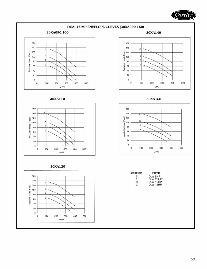
53
0
20
40
60
80
100
120
140
160
0 100 200 300 400 500
GPM
Ava
ilabl
e H
ead
(Fee
t)
7
8
B
C
0
20
40
60
80
100
120
140
160
0 100 200 300 400 500
GPM
Ava
ilabl
e H
ead
(Fee
t)
7
8
B
C
0
20
40
60
80
100
120
140
160
0 100 200 300 400 500
GPM
Ava
ilabl
e H
ead
(Fee
t)
7
8
B
C
0
20
40
60
80
100
120
140
160
0 100 200 300 400 500
GPM
Ava
ilabl
e H
ead
(Fee
t)
7
8
B
C
0
20
40
60
80
100
120
140
160
0 100 200 300 400 500
GPM
Ava
ilabl
e H
ead
(Fee
t)
7
8
B
C
30XA090,100
30XA110
30XA120
30XA140
30XA160
Selection Pump7 Dual 5HP8 Dual 7.5HPB Dual 10HPC Dual 15HP
a30-4436
a30-4437
a30-4438
a30-4439
a30-4440
DUAL PUMP ENVELOPE CURVES (30XA090-160)
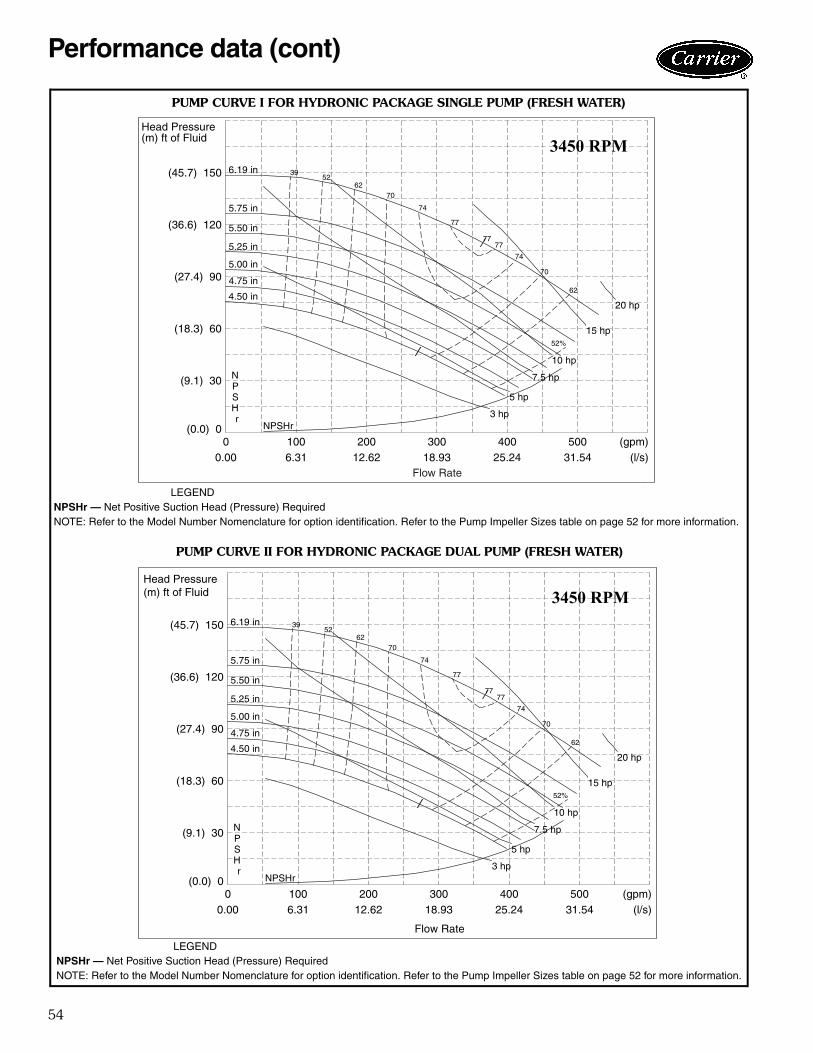
54
00.00
1006.31
20012.62
30018.93
40025.24
50031.54
(gpm)(l/s)
(0.0) 0
(9.1) 30
(18.3) 60
(27.4) 90
(36.6) 120
(45.7) 150
Head Pressure(m) ft of Fluid 3450 RPM
NPSHr
4.75 in
5.00 in
5.25 in
5.50 in
5.75 in77
77
74
74
70
70
62
62
52
52%
39
NPSHr3 hp
5 hp
7.5 hp
10 hp
15 hp
20 hp
6.19 in
4.50 in
77
Flow Rate
00.00
1006.31
20012.62
30018.93
40025.24
50031.54
(gpm)(l/s)
(0.0) 0
(9.1) 30
(18.3) 60
(27.4) 90
(36.6) 120
(45.7) 150
Head Pressure(m) ft of Fluid
Flow Rate
3450 RPM
NPSHr
4.75 in
5.00 in
5.25 in
5.50 in
5.75 in77
77
74
74
70
70
62
62
52
52%
39
NPSHr3 hp
5 hp
7.5 hp
10 hp
15 hp
20 hp
6.19 in
4.50 in
77
LEGENDNPSHr — Net Positive Suction Head (Pressure) RequiredNOTE: Refer to the Model Number Nomenclature for option identification. Refer to the Pump Impeller Sizes table on page 52 for more information.
LEGENDNPSHr — Net Positive Suction Head (Pressure) RequiredNOTE: Refer to the Model Number Nomenclature for option identification. Refer to the Pump Impeller Sizes table on page 52 for more information.
a30-4441
a30-4442
PUMP CURVE I FOR HYDRONIC PACKAGE SINGLE PUMP (FRESH WATER)
PUMP CURVE II FOR HYDRONIC PACKAGE DUAL PUMP (FRESH WATER)
Performance data (cont)
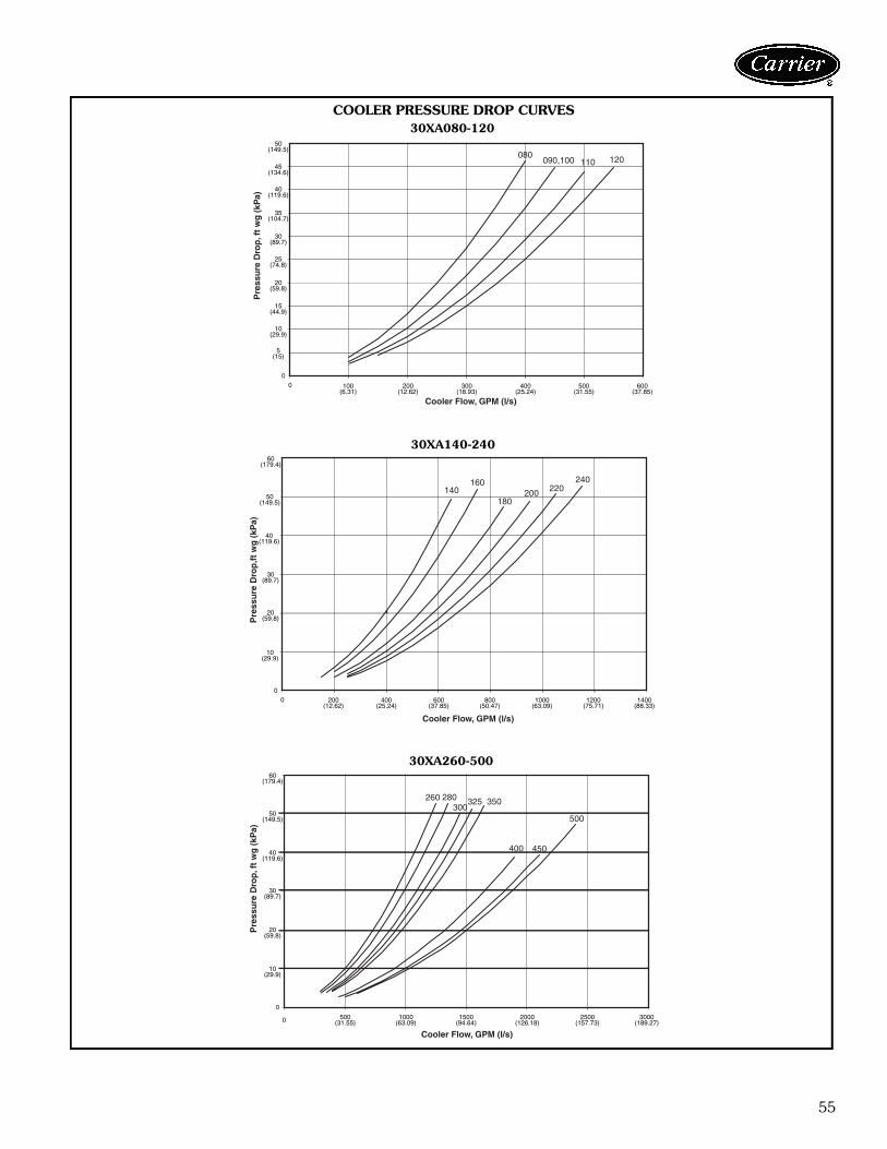
55
0
50(149.5)
0
Cooler Flow, GPM (l/s)
Pre
ssu
re D
rop
, ft
wg
(kP
a)
080090,100 110 120
45(134.6)
40(119.6)
35(104.7)
30(89.7)
25(74.8)
20(59.8)
15(44.9)
10(29.9)
5(15)
100(6.31)
200(12.62)
300(18.93)
400(25.24)
500(31.55)
600(37.85)
00
Cooler Flow, GPM (l/s)
Pre
ssu
re D
rop
,ft
wg
(kP
a)
140160
180200 220
240
60(179.4)
50(149.5)
40(119.6)
30(89.7)
20(59.8)
10(29.9)
200(12.62)
400(25.24)
600(37.85)
800(50.47)
1000(63.09)
1200(75.71)
1400(88.33)
0
0
260 280300
325 350
400 450
500
Pre
ssu
re D
rop
, ft
wg
(kP
a)
60(179.4)
50(149.5)
40(119.6)
30(89.7)
20(59.8)
10(29.9)
500(31.55)
1000(63.09)
1500(94.64)
2000(126.18)
2500(157.73)
3000(189.27)
Cooler Flow, GPM (l/s)
COOLER PRESSURE DROP CURVES30XA080-120
30XA140-240
30XA260-500
a30-4449
a30-4450
a30-4451
56
30XA PACKAGED AIR-COOLED CHILLER RATINGS TABLE — ENGLISH
LEGEND NOTES:1. All ratings are in accordance with ARI (Air Conditioning and Refrigeration
Institute, U.S.A.) Standard 550/590, based on:a. A cooler water temperature rise of 10° F. For other than a 10° F temper-
ature rise, data corrections must be made using the Packaged ChillerBuilder Program.
b. A fouling factor of 0.00010 (ft2 · hr · F/Btu) in the cooler.c. Refrigerant 134a.
2. Ratings generated are based on standard ambient temperature (850 rpmcondenser fan) units.
3. Data for 30XA450, 500, LCWT 50, Condenser Entering Air Temperature115 F not available at time of printing.
LCWT (F)30XA UNIT SIZE
CONDENSER ENTERING AIR TEMPERATURE (F)85 95 105 115
Cap. Tons
InputPower(kW)
CoolerFlow Rate
(gpm)
Cap. Tons
InputPower(kW)
CoolerFlow Rate
(gpm)
Cap. Tons
InputPower(kW)
CoolerFlow Rate
(gpm)
Cap. Tons
InputPower(kW)
CoolerFlow Rate
(gpm)
40
080 74.7 82.2 178.5 70.2 88.3 167.6 65.4 95.2 156.2 60.5 102.7 144.5090 82.4 84.9 196.7 79.2 92.7 189.1 75.8 101.6 181.1 72.3 111.3 172.6100 91.6 94.2 218.7 87.7 103.3 209.4 83.5 113.4 199.3 79.2 124.6 189.2110 100.4 103.5 239.8 96.2 113.7 229.7 91.6 124.9 218.7 86.8 137.6 207.3120 108.9 112.8 260.1 104.3 123.9 249.0 99.1 136.0 236.7 93.8 150.1 224.0140 129.4 131.6 309.1 124.5 144.7 297.3 119.2 159.2 284.7 113.6 175.0 271.3160 149.2 152.7 356.3 143.2 168.2 342.1 136.7 185.1 326.4 129.9 204.1 310.3180 166.5 170.1 397.5 160.3 186.8 382.9 153.8 205.1 367.3 146.9 225.2 350.8200 189.2 191.9 451.8 181.8 210.8 434.3 174.1 231.6 415.7 165.8 254.4 395.9220 205.4 211.6 490.5 197.3 232.8 471.1 188.5 256.3 450.2 179.1 282.6 427.8240 223.9 228.8 534.8 214.7 251.6 512.7 204.7 277.0 488.9 194.0 305.7 463.4260 244.1 248.0 583.1 234.9 272.7 561.1 225.2 300.2 537.8 214.9 330.8 513.1280 261.6 264.9 624.8 251.4 291.4 600.4 240.5 321.0 574.4 228.9 354.2 546.7300 282.2 284.0 674.0 271.1 311.4 647.6 259.1 342.9 618.9 246.3 378.2 588.3325 298.8 304.6 713.7 287.5 334.8 686.6 275.6 368.8 658.1 263.0 406.5 628.1350 318.1 325.0 759.7 305.8 357.2 730.4 292.8 393.5 699.4 279.1 434.1 666.6400 376.3 390.7 898.8 361.5 429.8 863.4 345.3 473.1 824.6 319.9 501.4 764.1450 417.8 444.9 997.7 401.3 490.0 958.4 383.9 540.3 916.8 324.5 539.7 774.9500 450.2 477.4 1075.3 431.9 525.7 1031.6 412.5 579.5 985.2 346.8 578.4 828.2
42
080 77.5 83.8 185.1 72.9 89.8 174.1 68.0 96.7 162.4 62.9 104.3 150.3090 85.1 85.9 203.4 81.8 93.8 195.5 78.3 102.7 187.2 74.6 112.6 178.4100 95.1 96.5 227.3 91.0 105.7 217.5 86.6 116.0 207.0 81.8 127.0 195.6110 103.7 105.8 247.9 99.3 116.2 237.4 94.5 127.6 225.9 89.5 140.5 213.9120 112.4 115.4 268.6 107.5 126.7 257.0 102.2 139.1 244.2 96.7 153.7 231.2140 133.8 133.5 319.8 128.7 146.7 307.6 123.2 161.3 294.5 117.4 177.3 280.5160 154.1 155.0 368.4 147.9 170.7 353.6 141.2 187.7 337.5 134.2 207.0 320.8180 172.2 172.7 411.6 165.9 189.5 396.5 159.1 208.0 380.3 152.0 228.2 363.1200 195.5 194.9 467.2 187.9 214.0 449.1 179.9 234.9 429.9 171.3 258.0 409.3220 213.0 214.4 509.1 204.5 235.8 488.8 195.5 259.5 467.1 185.7 286.1 443.9240 231.4 234.1 553.0 222.2 256.3 531.1 212.1 281.5 507.0 201.0 310.7 480.4260 252.5 252.3 603.6 243.0 277.2 580.7 232.8 305.0 556.4 222.1 335.9 530.8280 270.8 269.0 647.2 260.2 295.9 621.8 248.9 325.8 594.8 236.8 359.5 566.0300 290.9 290.9 695.1 279.4 318.8 667.7 267.3 350.0 638.9 251.6 379.0 601.4325 308.9 310.3 738.2 297.1 341.0 710.0 284.7 375.3 680.4 271.6 413.6 649.2350 327.7 333.5 783.2 315.2 365.8 753.4 302.1 401.9 722.0 285.7 440.3 682.8400 387.8 399.8 926.7 372.7 439.1 890.8 356.7 483.0 852.6 325.4 510.8 777.7450 431.0 454.1 1029.9 414.2 499.3 989.9 396.2 550.6 946.9 318.2 513.1 760.5500 463.6 489.7 1107.9 445.0 537.8 1063.6 425.3 591.8 1016.4 344.1 535.1 822.2
44
080 80.2 85.5 191.8 75.6 91.6 180.7 70.5 98.3 168.6 65.3 105.9 156.2090 88.0 87.2 210.4 84.8 95.1 202.7 80.9 103.9 193.3 77.0 113.8 184.2100 98.4 98.5 235.3 93.9 107.8 224.7 89.7 118.5 214.6 84.7 129.7 202.6110 107.0 108.2 255.9 102.4 118.6 244.9 97.5 130.3 233.1 92.3 143.6 220.8120 115.8 118.1 277.0 110.7 129.5 264.8 105.3 142.4 251.8 99.7 157.4 238.4140 138.2 135.3 330.5 132.8 148.7 317.7 127.2 163.5 304.3 121.2 179.6 289.8160 159.1 157.4 380.4 152.3 173.0 364.2 145.7 190.5 348.5 138.5 210.1 331.3180 177.8 175.1 425.2 171.3 192.1 409.7 164.4 210.9 393.1 157.1 231.3 375.6200 201.9 197.9 482.7 194.0 217.2 464.0 185.7 238.4 444.1 176.9 261.8 422.9220 219.9 218.8 525.9 211.7 239.6 506.2 202.4 262.8 484.0 192.4 289.7 460.1240 237.4 242.1 567.7 228.1 264.1 545.6 218.4 288.9 522.3 205.2 309.9 490.6260 260.9 256.5 623.9 250.9 281.7 600.2 240.5 310.0 575.2 229.4 341.2 548.6280 279.1 275.1 667.5 268.5 301.2 642.1 257.3 330.8 615.3 244.9 364.9 585.6300 299.4 297.8 715.9 287.5 326.3 687.6 275.0 358.4 657.7 256.8 379.5 614.1325 319.0 316.1 762.8 306.6 347.1 733.4 293.9 382.1 702.7 280.4 420.9 670.5350 337.3 342.0 806.6 324.1 374.8 775.1 310.6 411.9 742.8 289.6 444.7 692.5400 399.3 409.6 954.8 383.6 449.4 917.6 367.0 494.3 877.7 330.5 510.7 790.3450 443.5 465.5 1060.5 426.8 509.3 1020.8 408.0 562.4 975.6 331.3 522.0 792.3500 475.9 504.1 1138.1 458.0 549.2 1095.5 435.0 603.7 1040.1 349.8 552.1 836.5
Cap. — Cooling Capacity (Tons of Refrigeration)kW — Total PowerLCWT — Leaving Chilled Water Temperature
Performance data (cont)
57
30XA PACKAGED AIR-COOLED CHILLER RATINGS TABLE — ENGLISH (cont)
LEGEND NOTES:1. All ratings are in accordance with ARI (Air Conditioning and Refrigeration
Institute, U.S.A.) Standard 550/590, based on:a. A cooler water temperature rise of 10° F. For other than a 10° F temper-
ature rise, data corrections must be made using the Packaged ChillerBuilder Program.
b. A fouling factor of 0.00010 (ft2 · hr · F/Btu) in the cooler.c. Refrigerant 134a.
2. Ratings generated are based on standard ambient temperature (850 rpmcondenser fan) units.
3. Data for 30XA450, 500, LCWT 50, Condenser Entering Air Temperature115 F not available at time of printing.
LCWT (F)30XA UNIT SIZE
CONDENSER ENTERING AIR TEMPERATURE (F)85 95 105 115
Cap. Tons
InputPower(kW)
CoolerFlow Rate
(gpm)
Cap. Tons
InputPower(kW)
CoolerFlow Rate
(gpm)
Cap. Tons
InputPower(kW)
CoolerFlow Rate
(gpm)
Cap. Tons
InputPower(kW)
CoolerFlow Rate
(gpm)
46
080 83.1 87.3 198.9 78.2 93.4 187.2 73.1 100.2 175.0 67.9 107.6 162.4090 91.4 89.0 218.6 87.6 96.8 209.6 83.6 105.6 200.1 79.5 115.3 190.2100 101.6 100.7 243.1 97.4 110.3 232.9 92.8 121.0 222.1 87.8 132.5 210.0110 110.4 110.6 264.1 105.6 121.2 252.7 100.6 133.2 240.8 95.2 146.7 227.9120 119.4 120.9 285.7 114.1 132.4 273.0 108.5 145.7 259.7 102.8 161.2 245.9140 142.8 137.3 341.6 137.3 150.8 328.5 131.4 165.7 314.5 125.2 182.0 299.6160 164.0 160.4 392.5 157.5 176.1 376.8 150.5 193.4 360.1 143.1 213.3 342.4180 183.6 177.7 439.4 176.9 194.9 423.3 169.7 213.8 406.2 162.2 234.4 388.1200 208.2 201.8 498.2 200.4 220.7 479.4 191.8 242.1 459.0 182.7 265.7 437.1220 226.2 224.9 541.2 217.8 245.3 521.2 208.7 268.9 499.4 198.9 295.1 475.8240 243.4 250.7 582.5 233.9 273.5 559.7 223.8 299.2 535.4 208.3 311.8 498.4260 269.0 261.9 643.7 259.0 286.9 619.8 248.5 315.0 594.6 237.1 346.7 567.3280 287.4 282.1 687.7 276.5 308.8 661.5 264.9 338.7 633.9 252.7 372.1 604.8300 307.4 306.8 735.6 295.6 335.0 707.3 282.8 367.1 676.7 262.0 379.9 627.0325 329.6 322.0 788.6 316.8 353.7 758.0 303.5 389.1 726.2 289.5 428.4 692.8350 347.2 351.1 830.8 333.7 384.9 798.5 319.6 422.6 764.6 293.6 449.1 702.4400 410.0 421.3 981.1 394.1 461.8 942.9 377.2 507.0 902.4 317.1 470.7 758.8450 455.8 477.0 1090.7 438.0 523.8 1047.9 415.2 569.0 993.4 336.1 516.9 804.2500 488.0 519.4 1167.6 468.6 568.7 1121.3 441.9 614.1 1057.5 360.7 557.0 863.1
48
080 86.1 89.1 206.1 81.0 95.3 194.0 75.8 102.2 181.4 70.3 102.0 168.4090 94.7 90.7 226.7 90.7 98.7 217.2 86.6 107.6 207.3 82.2 107.2 196.8100 104.8 102.9 250.8 100.4 112.7 240.3 95.6 123.5 229.0 90.5 124.9 216.6110 113.7 113.1 272.3 108.8 123.9 260.4 103.6 136.2 248.1 98.1 139.8 234.8120 123.0 123.8 294.5 117.4 135.5 281.1 111.7 149.3 267.5 105.8 154.9 253.3140 147.4 139.2 352.9 141.7 152.9 339.3 135.7 168.0 324.8 129.2 171.5 309.3160 168.4 164.9 403.3 161.8 180.2 387.4 154.9 197.4 370.8 147.4 204.1 353.0180 189.5 180.3 453.7 182.5 197.6 437.0 175.1 216.7 419.3 167.3 222.1 400.6200 213.7 208.0 511.4 205.7 226.6 492.5 197.4 247.1 472.6 188.3 254.6 450.9220 232.0 232.3 555.4 223.3 253.3 534.5 214.0 276.8 512.3 202.2 277.6 484.0240 249.4 259.4 597.1 239.4 283.1 573.3 228.8 309.7 547.8 208.8 288.8 499.8260 277.0 268.2 663.2 266.6 293.6 638.4 255.7 321.8 612.4 244.3 333.8 584.9280 295.7 289.3 708.0 284.4 316.5 680.8 272.4 347.1 652.1 257.7 352.3 617.0300 315.1 317.4 754.3 302.7 346.4 724.7 287.7 370.2 688.9 266.5 360.8 638.2325 339.9 328.9 813.8 327.0 360.3 783.0 313.2 396.1 749.9 298.7 412.9 715.2350 356.9 361.1 854.4 343.2 395.0 821.6 328.4 433.7 786.2 287.2 398.2 687.5400 420.9 433.4 1007.7 404.4 474.8 968.0 386.8 521.4 925.9 325.8 473.9 780.1450 468.1 490.3 1120.6 450.0 537.3 1077.3 422.6 575.7 1011.6 349.1 525.5 835.8500 499.5 537.6 1195.8 479.4 588.1 1147.7 448.1 626.1 1072.8 361.9 546.2 866.3
50
080 89.0 91.1 213.3 83.9 97.3 200.9 78.5 104.3 188.0 72.9 104.2 174.6090 97.8 92.4 234.4 93.9 100.6 224.9 89.6 109.7 214.7 85.1 109.5 203.7100 108.0 105.0 258.6 103.4 115.0 247.8 98.5 126.0 236.0 93.2 127.6 223.2110 117.1 115.6 280.5 112.0 126.6 268.2 106.7 139.3 255.5 101.0 143.2 241.8120 126.6 126.6 303.3 120.8 138.6 289.4 115.0 153.1 275.6 108.9 159.1 260.9140 152.1 141.2 364.3 146.2 155.0 350.1 140.0 170.2 335.3 133.3 173.9 319.2160 172.8 169.5 413.8 165.9 185.2 397.4 158.8 202.8 380.4 151.2 209.7 362.3180 195.4 182.9 468.1 188.2 200.4 450.8 180.6 219.6 432.6 172.6 225.2 413.4200 219.0 214.3 524.7 210.8 233.4 505.0 202.2 254.3 484.4 193.0 262.0 462.4220 237.7 239.9 569.3 228.7 261.6 547.7 219.1 285.7 524.8 210.4 291.5 504.0240 255.2 268.5 611.4 244.9 293.2 586.6 232.0 311.9 555.8 218.3 301.7 523.0260 284.2 276.2 680.8 273.8 301.5 655.9 262.9 329.5 629.8 252.9 336.9 605.9280 303.1 298.5 726.1 291.7 325.8 698.6 279.6 356.4 669.8 268.8 364.5 643.9300 322.7 328.4 772.9 309.8 358.3 742.1 292.3 373.8 700.2 278.5 373.5 667.0325 348.9 338.6 835.7 335.9 370.0 804.6 322.4 404.9 772.3 310.1 415.2 742.7350 365.7 372.7 876.1 351.6 407.4 842.2 334.6 442.8 801.5 312.8 440.6 749.4400 430.9 447.6 1032.1 414.1 489.6 991.8 394.3 527.7 944.5 330.8 470.4 792.3450 479.6 505.2 1148.8 460.7 553.5 1103.6 419.6 548.9 1005.2 353.1 519.1 845.8500 510.6 556.2 1223.1 489.8 608.3 1173.1 445.5 601.1 1067.2 — — —
Cap. — Cooling Capacity (Tons of Refrigeration)kW — Total PowerLCWT — Leaving Chilled Water Temperature
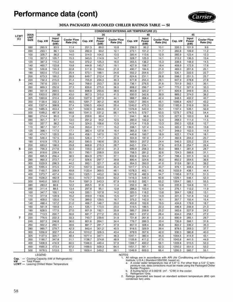
58
30XA PACKAGED AIR-COOLED CHILLER RATINGS TABLE — SI
LEGEND NOTES:1. All ratings are in accordance with ARI (Air Conditioning and Refrigeration
Institute, U.S.A.) Standard 550/590, based on:a. A cooler water temperature rise of 5.6° C. For other than a 5.6° C tem-
perature rise, data corrections must be made using the Packaged ChillerBuilder Program.
b. A fouling factor of 0.00018 (m2 · °C/W) in the cooler.c. Refrigerant 134a.
2. Ratings generated are based on standard ambient temperature (850 rpmcondenser fan) units.
LCWT(C)
30XAUNIT SIZE
CONDENSER ENTERING AIR TEMPERATURE (C)30 35 40 45
Cap. kWInputPower(kW)
Cooler Flow Rate (l/s) Cap. kW
InputPower(kW)
Cooler Flow Rate (l/s) Cap. kW
InputPower(kW)
Cooler Flow Rate (l/s) Cap. kW
InputPower(kW)
Cooler Flow Rate (l/s)
5
080 265.9 83.5 11.4 251.3 89.0 10.8 236.0 95.2 10.1 220.3 101.9 9.6090 293.1 86.1 12.6 282.9 93.2 12.1 272.1 101.2 11.7 260.8 109.9 11.2100 326.7 96.2 14.0 314.0 104.5 13.5 300.4 113.6 12.9 285.9 123.4 12.3110 357.2 105.7 15.3 343.5 114.9 14.7 328.7 125.0 14.1 313.2 136.3 13.4120 387.3 115.2 16.6 372.2 125.3 16.0 355.5 136.2 15.3 338.6 148.9 14.5140 460.7 133.8 19.8 444.8 145.7 19.1 427.9 158.7 18.4 409.9 172.9 17.6160 530.8 155.3 22.8 511.6 169.4 21.9 490.7 184.6 21.0 469.0 201.6 20.1180 593.0 173.0 25.4 573.1 188.1 24.6 552.2 204.6 23.7 530.1 222.5 22.7200 673.3 195.2 28.9 649.7 212.4 27.9 624.6 231.1 26.8 598.2 251.5 25.7220 732.3 215.0 31.4 705.9 234.3 30.3 677.8 255.4 29.1 647.9 278.8 27.8240 797.6 233.1 34.2 768.0 253.7 32.9 736.1 276.5 31.6 701.9 302.1 30.1260 869.3 252.6 37.3 839.6 275.0 36.0 808.2 299.7 34.7 775.2 327.0 33.3280 931.9 269.5 40.0 898.8 293.6 38.6 863.8 320.2 37.1 826.8 349.9 35.5300 1003.0 290.0 43.0 967.3 315.0 41.5 930.0 342.6 39.9 889.2 374.0 38.2325 1063.6 310.4 45.6 1027.0 337.9 44.1 988.7 368.4 42.4 948.5 402.2 40.7350 1130.4 332.3 48.5 1091.7 361.2 46.8 1050.7 393.4 45.1 1006.8 429.7 43.2400 1337.4 398.8 57.4 1290.5 434.0 55.4 1240.2 473.3 53.2 1185.9 516.9 50.9450 1485.3 453.4 63.7 1432.4 494.6 61.4 1376.9 540.0 59.1 1197.4 539.1 50.9500 1599.2 487.9 68.6 1541.5 531.2 66.1 1479.5 579.7 63.5 1279.7 578.2 54.4
6
080 274.4 85.0 11.8 259.6 90.4 11.1 244.1 96.6 10.5 227.9 103.3 9.8090 301.7 87.1 13.0 291.2 94.2 12.5 280.0 102.2 12.0 268.3 111.0 11.5100 337.7 98.2 14.5 324.5 106.6 13.9 310.4 115.9 13.3 295.3 125.8 12.7110 367.7 107.7 15.8 353.4 117.1 15.2 338.1 127.4 14.5 322.2 139.0 13.8120 398.1 117.5 17.1 382.4 127.8 16.4 365.3 139.1 15.7 348.0 152.0 14.9140 474.7 135.5 20.4 458.1 147.5 19.7 440.6 160.7 18.9 422.1 174.9 18.1160 546.4 157.5 23.5 526.4 171.7 22.6 504.9 187.0 21.7 482.6 204.2 20.7180 610.9 175.3 26.2 590.5 190.6 25.3 569.0 207.2 24.4 546.3 225.2 23.4200 693.2 198.0 29.8 668.8 215.3 28.7 643.1 234.1 27.6 615.8 254.7 26.4220 756.3 217.6 32.5 729.0 237.0 31.3 699.9 258.3 30.0 669.1 281.9 28.7240 818.6 239.4 35.1 790.1 258.9 33.9 758.5 281.2 32.6 724.3 306.6 31.1260 895.9 256.4 38.5 864.9 279.1 37.1 832.6 304.0 35.7 798.4 331.5 34.3280 960.3 273.7 41.2 926.6 297.7 39.8 890.4 324.6 38.2 852.2 354.5 36.6300 1029.9 296.3 44.2 993.1 321.7 42.6 954.3 350.0 41.0 913.6 381.0 39.2325 1095.4 315.5 47.0 1057.3 343.4 45.4 1017.7 374.3 43.7 976.1 408.4 41.9350 1160.7 339.9 49.8 1120.4 369.5 48.1 1078.3 402.1 46.3 1033.9 438.1 44.4400 1373.7 407.4 59.0 1325.1 443.2 56.9 1273.8 482.9 54.7 1195.6 517.0 51.3450 1526.2 462.9 65.5 1472.7 503.9 63.2 1416.3 549.3 60.8 1229.1 546.1 52.3500 1640.0 500.0 70.4 1581.3 543.3 67.9 1518.2 592.1 65.2 1304.7 585.1 55.5
7
080 283.2 86.6 12.2 265.5 91.6 11.4 252.3 98.1 10.8 235.9 104.8 10.1090 311.4 88.5 13.4 297.8 95.1 12.8 288.2 103.4 12.4 276.1 112.2 11.9100 347.7 100.1 14.9 330.1 107.8 14.2 320.5 118.2 13.8 304.7 128.2 13.1110 377.9 109.9 16.2 359.9 118.6 15.5 347.7 130.0 14.9 331.3 141.8 14.2120 409.0 120.0 17.6 389.0 129.5 16.7 375.2 142.0 16.1 357.7 155.4 15.4140 488.4 137.2 21.0 466.7 148.7 20.0 453.6 162.6 19.5 434.6 176.9 18.7160 561.9 159.8 24.1 535.1 173.0 23.0 519.5 189.5 22.3 496.8 206.9 21.3180 628.5 177.5 27.0 601.9 192.1 25.8 585.7 209.8 25.2 562.6 227.9 24.2200 713.5 200.7 30.6 681.7 217.2 29.3 662.1 237.2 28.4 634.0 258.1 27.2220 776.5 222.3 33.3 743.7 239.6 31.9 721.8 261.8 31.0 690.9 285.1 29.7240 837.3 246.8 36.0 801.6 264.1 34.4 776.7 289.3 33.4 735.9 306.1 31.6260 922.2 260.1 39.6 881.7 281.7 37.9 857.3 308.4 36.8 822.2 336.2 35.3280 985.7 279.7 42.3 943.4 301.2 40.5 916.5 329.9 39.4 878.5 359.3 37.7300 1056.9 302.7 45.4 1010.2 326.3 43.4 978.9 357.6 42.0 930.3 380.8 40.0325 1127.5 320.7 48.4 1077.4 347.1 46.3 1047.1 380.4 45.0 1004.5 414.9 43.1350 1190.7 347.8 51.1 1138.7 374.8 48.9 1105.8 411.2 47.5 1045.8 441.5 44.9400 1408.9 416.9 60.5 1348.0 449.4 57.9 1306.7 493.2 56.1 1209.8 515.5 52.0450 1565.3 473.4 67.2 1499.5 509.3 64.4 1451.7 561.1 62.3 1250.2 551.0 53.2500 1678.5 513.0 72.1 1609.4 549.2 69.1 1546.9 603.0 66.4 1295.3 560.7 55.1
Cap. — Cooling Capacity (kW of Refrigeration)kW — Total PowerLCWT — Leaving Chilled Water Temperature
Performance data (cont)
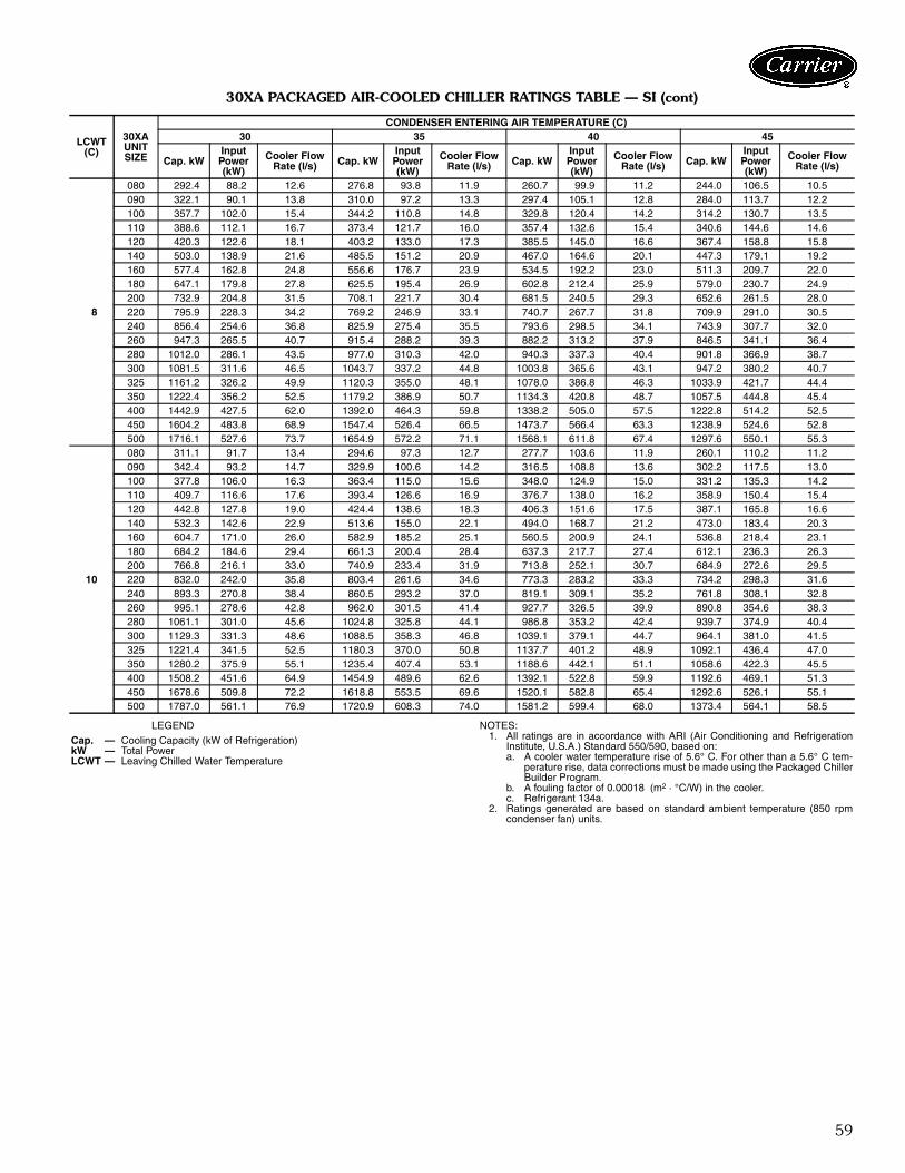
59
30XA PACKAGED AIR-COOLED CHILLER RATINGS TABLE — SI (cont)
LEGEND NOTES:1. All ratings are in accordance with ARI (Air Conditioning and Refrigeration
Institute, U.S.A.) Standard 550/590, based on:a. A cooler water temperature rise of 5.6° C. For other than a 5.6° C tem-
perature rise, data corrections must be made using the Packaged ChillerBuilder Program.
b. A fouling factor of 0.00018 (m2 · °C/W) in the cooler.c. Refrigerant 134a.
2. Ratings generated are based on standard ambient temperature (850 rpmcondenser fan) units.
LCWT(C)
30XAUNIT SIZE
CONDENSER ENTERING AIR TEMPERATURE (C)30 35 40 45
Cap. kWInputPower(kW)
Cooler Flow Rate (l/s) Cap. kW
InputPower(kW)
Cooler Flow Rate (l/s) Cap. kW
InputPower(kW)
Cooler Flow Rate (l/s) Cap. kW
InputPower(kW)
Cooler Flow Rate (l/s)
8
080 292.4 88.2 12.6 276.8 93.8 11.9 260.7 99.9 11.2 244.0 106.5 10.5090 322.1 90.1 13.8 310.0 97.2 13.3 297.4 105.1 12.8 284.0 113.7 12.2100 357.7 102.0 15.4 344.2 110.8 14.8 329.8 120.4 14.2 314.2 130.7 13.5110 388.6 112.1 16.7 373.4 121.7 16.0 357.4 132.6 15.4 340.6 144.6 14.6120 420.3 122.6 18.1 403.2 133.0 17.3 385.5 145.0 16.6 367.4 158.8 15.8140 503.0 138.9 21.6 485.5 151.2 20.9 467.0 164.6 20.1 447.3 179.1 19.2160 577.4 162.8 24.8 556.6 176.7 23.9 534.5 192.2 23.0 511.3 209.7 22.0180 647.1 179.8 27.8 625.5 195.4 26.9 602.8 212.4 25.9 579.0 230.7 24.9200 732.9 204.8 31.5 708.1 221.7 30.4 681.5 240.5 29.3 652.6 261.5 28.0220 795.9 228.3 34.2 769.2 246.9 33.1 740.7 267.7 31.8 709.9 291.0 30.5240 856.4 254.6 36.8 825.9 275.4 35.5 793.6 298.5 34.1 743.9 307.7 32.0260 947.3 265.5 40.7 915.4 288.2 39.3 882.2 313.2 37.9 846.5 341.1 36.4280 1012.0 286.1 43.5 977.0 310.3 42.0 940.3 337.3 40.4 901.8 366.9 38.7300 1081.5 311.6 46.5 1043.7 337.2 44.8 1003.8 365.6 43.1 947.2 380.2 40.7325 1161.2 326.2 49.9 1120.3 355.0 48.1 1078.0 386.8 46.3 1033.9 421.7 44.4350 1222.4 356.2 52.5 1179.2 386.9 50.7 1134.3 420.8 48.7 1057.5 444.8 45.4400 1442.9 427.5 62.0 1392.0 464.3 59.8 1338.2 505.0 57.5 1222.8 514.2 52.5450 1604.2 483.8 68.9 1547.4 526.4 66.5 1473.7 566.4 63.3 1238.9 524.6 52.8500 1716.1 527.6 73.7 1654.9 572.2 71.1 1568.1 611.8 67.4 1297.6 550.1 55.3
10
080 311.1 91.7 13.4 294.6 97.3 12.7 277.7 103.6 11.9 260.1 110.2 11.2090 342.4 93.2 14.7 329.9 100.6 14.2 316.5 108.8 13.6 302.2 117.5 13.0100 377.8 106.0 16.3 363.4 115.0 15.6 348.0 124.9 15.0 331.2 135.3 14.2110 409.7 116.6 17.6 393.4 126.6 16.9 376.7 138.0 16.2 358.9 150.4 15.4120 442.8 127.8 19.0 424.4 138.6 18.3 406.3 151.6 17.5 387.1 165.8 16.6140 532.3 142.6 22.9 513.6 155.0 22.1 494.0 168.7 21.2 473.0 183.4 20.3160 604.7 171.0 26.0 582.9 185.2 25.1 560.5 200.9 24.1 536.8 218.4 23.1180 684.2 184.6 29.4 661.3 200.4 28.4 637.3 217.7 27.4 612.1 236.3 26.3200 766.8 216.1 33.0 740.9 233.4 31.9 713.8 252.1 30.7 684.9 272.6 29.5220 832.0 242.0 35.8 803.4 261.6 34.6 773.3 283.2 33.3 734.2 298.3 31.6240 893.3 270.8 38.4 860.5 293.2 37.0 819.1 309.1 35.2 761.8 308.1 32.8260 995.1 278.6 42.8 962.0 301.5 41.4 927.7 326.5 39.9 890.8 354.6 38.3280 1061.1 301.0 45.6 1024.8 325.8 44.1 986.8 353.2 42.4 939.7 374.9 40.4300 1129.3 331.3 48.6 1088.5 358.3 46.8 1039.1 379.1 44.7 964.1 381.0 41.5325 1221.4 341.5 52.5 1180.3 370.0 50.8 1137.7 401.2 48.9 1092.1 436.4 47.0350 1280.2 375.9 55.1 1235.4 407.4 53.1 1188.6 442.1 51.1 1058.6 422.3 45.5400 1508.2 451.6 64.9 1454.9 489.6 62.6 1392.1 522.8 59.9 1192.6 469.1 51.3450 1678.6 509.8 72.2 1618.8 553.5 69.6 1520.1 582.8 65.4 1292.6 526.1 55.1500 1787.0 561.1 76.9 1720.9 608.3 74.0 1581.2 599.4 68.0 1373.4 564.1 58.5
Cap. — Cooling Capacity (kW of Refrigeration)kW — Total PowerLCWT — Leaving Chilled Water Temperature
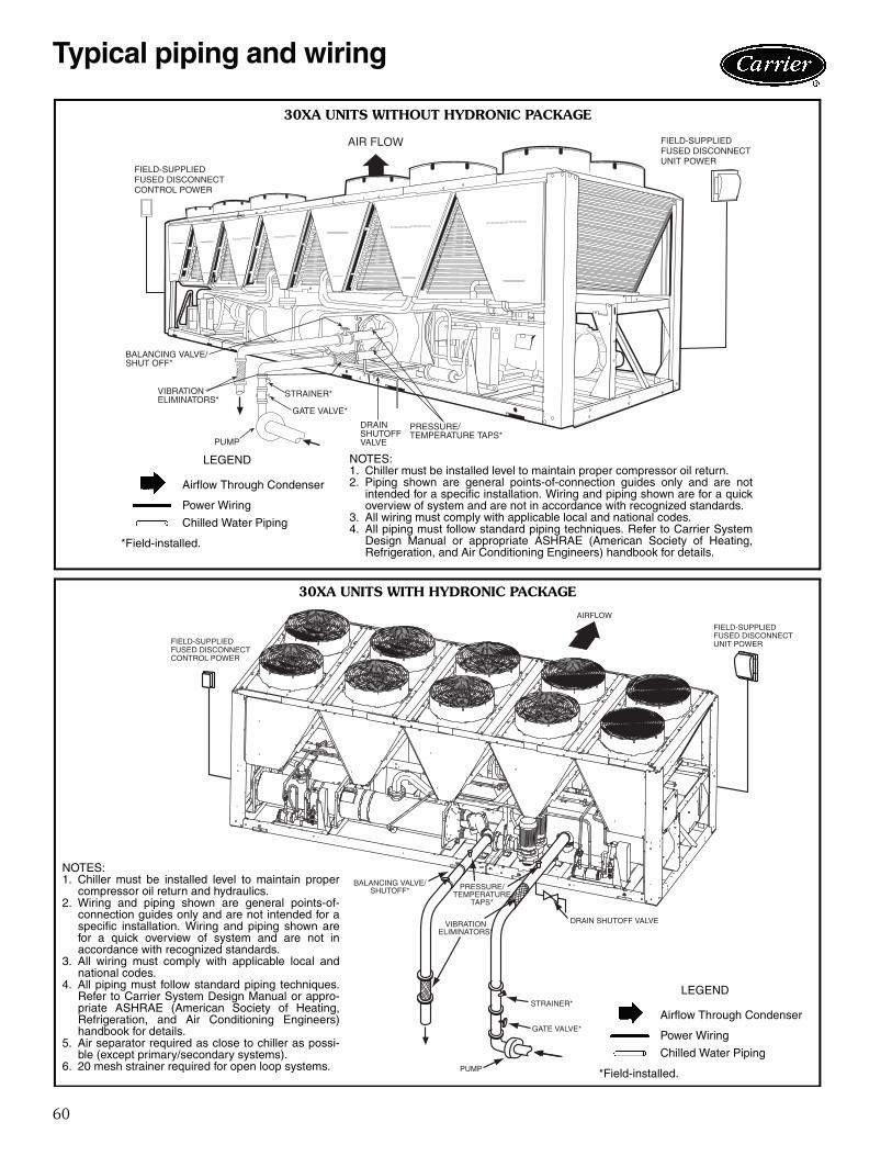
60
GATE VALVE*
STRAINER* VIBRATIONELIMINATORS*
BALANCING VALVE/SHUT OFF*
FIELD-SUPPLIEDFUSED DISCONNECTCONTROL POWER
PRESSURE/TEMPERATURE TAPS*
PUMP
DRAINSHUTOFFVALVE
FIELD-SUPPLIEDFUSED DISCONNECTUNIT POWER
FIELD-SUPPLIEDFUSED DISCONNECTCONTROL POWER
FIELD-SUPPLIEDFUSED DISCONNECTUNIT POWER
AIRFLOW
DRAIN SHUTOFF VALVE
STRAINER*
GATE VALVE*
PUMP
PRESSURE/TEMPERATURE
TAPS*
VIBRATIONELIMINATORS*
BALANCING VALVE/SHUTOFF*
30XA UNITS WITHOUT HYDRONIC PACKAGE
NOTES:1. Chiller must be installed level to maintain proper compressor oil return.2. Piping shown are general points-of-connection guides only and are not
intended for a specific installation. Wiring and piping shown are for a quickoverview of system and are not in accordance with recognized standards.
3. All wiring must comply with applicable local and national codes.4. All piping must follow standard piping techniques. Refer to Carrier System
Design Manual or appropriate ASHRAE (American Society of Heating,Refrigeration, and Air Conditioning Engineers) handbook for details.
LEGEND
*Field-installed.
Airflow Through Condenser
Power Wiring
Chilled Water Piping
30XA UNITS WITH HYDRONIC PACKAGE
NOTES:1. Chiller must be installed level to maintain proper
compressor oil return and hydraulics.2. Wiring and piping shown are general points-of-
connection guides only and are not intended for aspecific installation. Wiring and piping shown arefor a quick overview of system and are not inaccordance with recognized standards.
3. All wiring must comply with applicable local andnational codes.
4. All piping must follow standard piping techniques.Refer to Carrier System Design Manual or appro-priate ASHRAE (American Society of Heating,Refrigeration, and Air Conditioning Engineers)handbook for details.
5. Air separator required as close to chiller as possi-ble (except primary/secondary systems).
6. 20 mesh strainer required for open loop systems.
LEGEND
*Field-installed.
Airflow Through Condenser
Power Wiring
Chilled Water Piping
a30-4452
a30-4459
Typical piping and wiring
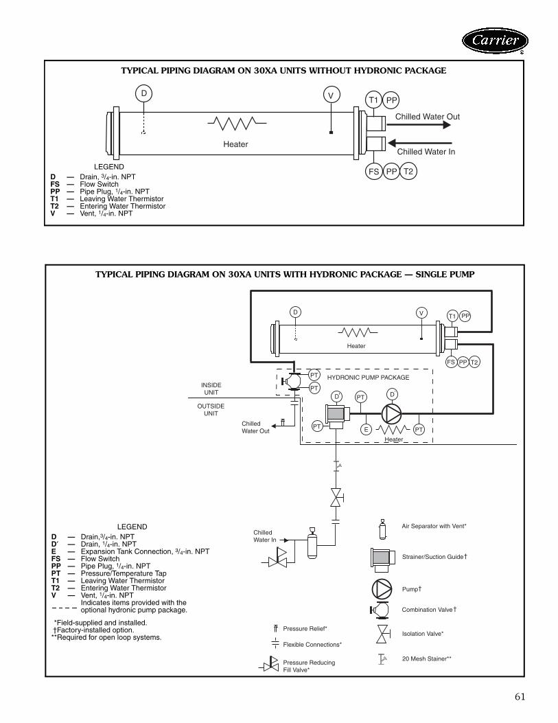
61
T1
T2
PP
PP
D V
Heater
Chilled Water Out
Chilled Water In
FSLEGEND
D — Drain, 3/4-in. NPTFS — Flow SwitchPP — Pipe Plug, 1/4-in. NPTT1 — Leaving Water ThermistorT2 — Entering Water ThermistorV — Vent, 1/4-in. NPT
TYPICAL PIPING DIAGRAM ON 30XA UNITS WITHOUT HYDRONIC PACKAGE
a30-4416
PT
PT
T1
T2FS
PP
PP
D
D V
D
PT
PT
ChilledWater In
ChilledWater Out
Heater
Heater
E PT
Air Separator with Vent*
Strainer/Suction Guide
Pump
Combination Valve
Isolation Valve*
Pressure Reducing Fill Valve*
Flexible Connections*
Pressure Relief*
HYDRONIC PUMP PACKAGE INSIDEUNIT
OUTSIDEUNIT
20 Mesh Stainer**
LEGEND
*Field-supplied and installed.†Factory-installed option.**Required for open loop systems.
D — Drain,3/4-in. NPTD′ — Drain, 1/4-in. NPTE — Expansion Tank Connection, 3/4-in. NPTFS — Flow SwitchPP — Pipe Plug, 1/4-in. NPTPT — Pressure/Temperature TapT1 — Leaving Water ThermistorT2 — Entering Water ThermistorV — Vent, 1/4-in. NPT
Indicates items provided with the optional hydronic pump package.
a30-4414
TYPICAL PIPING DIAGRAM ON 30XA UNITS WITH HYDRONIC PACKAGE — SINGLE PUMP
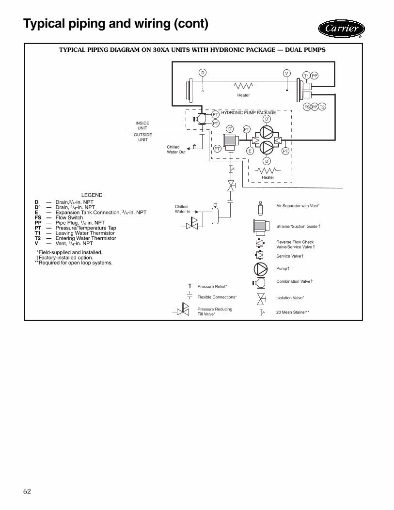
62
PT
PT
T1 PP
PP
D
D V
D
PT
PT
ChilledWater Out
Heater
Heater
E
D
PT
Air Separator with Vent*
Strainer/Suction Guide
Reverse Flow Check Valve/Service Valve
Pump
Service Valve
Combination Valve
Isolation Valve*
Pressure Reducing Fill Valve*
Flexible Connections*
Pressure Relief*
ChilledWater In
HYDRONIC PUMP PACKAGE
INSIDEUNIT
OUTSIDEUNIT
20 Mesh Stainer**
T2FS
LEGEND
*Field-supplied and installed.†Factory-installed option.**Required for open loop systems.
D — Drain,3/4-in. NPTD′ — Drain, 1/4-in. NPTE — Expansion Tank Connection, 3/4-in. NPTFS — Flow SwitchPP — Pipe Plug, 1/4-in. NPTPT — Pressure/Temperature TapT1 — Leaving Water ThermistorT2 — Entering Water ThermistorV — Vent, 1/4-in. NPT
a30-4415
TYPICAL PIPING DIAGRAM ON 30XA UNITS WITH HYDRONIC PACKAGE — DUAL PUMPS
Typical piping and wiring (cont)
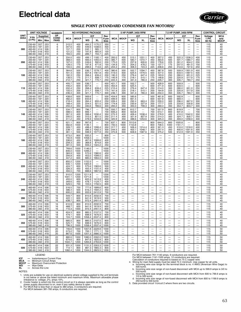
63
SINGLE POINT (STANDARD CONDENSER FAN MOTORS)*
LEGEND
NOTES:
1. Units are suitable for use on electrical systems where voltage supplied to the unit terminalsis not below or above the listed minimum and maximum limits. Maximum allowable phaseimbalance is: voltage, 2%; amps 10%.
2. Cooler heater is wired into the control circuit so it is always operable as long as the controlpower supply disconnect is on, even if any safety device is open.
3. For MCA that is less than or equal to 380 amps, 3 conductors are required.For MCA between 381-760 amps, 6 conductors are required.
For MCA between 761-1140 amps, 9 conductors are required.For MCA between 1141-1520 amps, 12 conductors are required.Calculation of conductors required is based on 75 C copper wire.
4. Wiring for main field supply must be rated 75 C minimum. Use copper for all units.a. Incoming wire size range for the terminal block is no. 4 AWG (American Wire Gage) to
500 kcmil.b. Incoming wire size range of non-fused disconnect with MCA up to 599.9 amps is 3/0 to
500 kcmil.c. Incoming wire size range of non-fused disconnect with MCA from 600 to 799.9 amps is
1/0 to 500 kcmil.d. Incoming wire size range of non-fused disconnect with MCA from 800 to 1199.9 amps is
250 kcmil to 500 kcmil.5. Data provided circuit 1/circuit 2 where there are two circuits.
UNIT30XA
UNIT VOLTAGE NUMBEROF
CONDFANS
NO HYDRONIC PACKAGE 5 HP PUMP, 3450 RPM 7.5 HP PUMP, 3450 RPM CONTROL CIRCUIT
V-Hz(3 Ph)
Supplied MCA MOCP
ICF RecFuseSize
MCA MOCPICF Rec
FuseSize
MCA MOCPICF Rec
FuseSize
Voltage1 PH, 60 Hz
MCA and
MOCPMin Max WD XL WD XL WD XL
080
230-60 207 253 6 315.5 400 484.2 1170.2 350 — — — — — — — — — — 115 40200-60 187 220 6 347.6 450 549.6 1338.6 400 — — — — — — — — — — 115 40460-60 414 506 6 157.7 200 242.1 585.1 175 — — — — — — — — — — 115 40575-60 518 633 6 121.2 150 191.9 465.9 150 — — — — — — — — — — 115 40380-60 342 418 6 183.5 250 289.7 704.7 225 — — — — — — — — — — 115 40
090
230-60 207 253 8 334.0 450 499.1 1185.1 400 350.0 450 515.1 1201.1 400 357.2 450 522.3 1208.3 400 115 40200-60 187 220 8 368.0 500 566.0 1355.0 450 385.7 500 583.7 1372.7 450 393.6 500 591.7 1380.7 450 115 40460-60 414 506 8 167.0 225 249.6 592.6 200 175.0 225 257.6 600.6 200 178.6 225 261.2 604.2 200 115 40575-60 518 633 8 128.5 175 197.8 471.8 150 134.9 175 204.2 478.2 150 137.7 175 207.0 481.0 150 115 40380-60 342 418 8 194.5 250 298.6 713.6 225 204.2 250 308.3 723.3 225 208.6 250 312.6 727.6 250 115 40
100
230-60 207 253 8 364.6 500 536.7 1278.7 400 380.6 500 552.7 1294.7 450 387.8 500 559.9 1301.9 450 115 40200-60 187 220 8 401.3 500 607.8 1461.8 450 419.0 500 625.5 1479.5 500 427.0 500 633.5 1487.5 500 115 40460-60 414 506 8 182.3 250 268.4 639.4 200 190.3 250 276.4 647.4 225 193.9 250 280.0 651.0 225 115 40575-60 518 633 8 139.5 175 211.7 508.7 175 145.9 175 218.1 515.1 175 148.8 200 220.9 517.9 175 115 40380-60 342 418 8 212.7 250 321.7 770.7 250 222.4 300 331.3 780.3 250 226.7 300 335.7 784.7 250 115 40
110
230-60 207 253 8 405.7 500 536.7 — 450 421.7 500 552.7 — 500 428.9 600 559.9 — 500 115 40200-60 187 220 8 446.2 600 607.8 — 500 463.9 600 625.5 — 600 471.9 600 633.5 — 600 115 40460-60 414 506 8 202.4 250 268.4 639.4 225 210.4 250 276.4 647.4 250 214.0 300 280.0 651.0 250 115 40575-60 518 633 8 155.5 200 211.7 508.7 175 161.9 225 218.1 515.1 200 164.8 225 220.9 517.9 200 115 40380-60 342 418 8 236.4 300 321.7 770.7 300 246.1 300 331.3 780.3 300 250.4 350 335.7 784.7 300 115 40
120
230-60 207 253 8 438.6 600 569.6 — 500 454.6 600 585.6 — 500 461.8 600 592.8 — 600 115 40200-60 187 220 8 482.2 600 643.8 — 600 499.9 600 661.5 — 600 507.8 600 669.4 — 600 115 40460-60 414 506 8 218.4 300 284.4 655.4 250 226.4 300 292.4 663.4 250 230.0 300 296.0 667.0 300 115 40575-60 518 633 8 168.4 225 224.5 521.5 200 174.8 225 230.9 527.9 200 177.7 225 233.8 530.8 200 115 40380-60 342 418 8 255.3 350 340.6 789.6 300 265.0 350 350.3 799.3 300 269.4 350 354.7 803.7 300 115 40
140
230-60 207 253 10 534.7 800 796.7 — 700 550.7 800 812.7 — 700 557.9 800 819.9 — 700 115 40200-60 187 220 10 588.5 800 906.1 — 700 606.2 800 923.8 — 700 614.1 800 931.8 — 700 115 40460-60 414 506 10 267.3 400 398.4 1030.4 350 275.3 400 406.4 1038.4 350 278.9 400 410.0 1042.0 350 115 40575-60 518 633 10 205.0 300 315.5 821.5 250 211.4 300 321.9 827.9 250 214.3 300 324.7 830.7 250 115 40380-60 342 418 10 311.2 450 478.9 1243.9 350 320.9 450 488.6 1253.6 400 325.3 450 493.0 1258.0 400 115 40
160
230-60 207 253 10 621.1 800 997.6 — 700 637.1 800 1013.6 — 800 644.3 800 1020.8 — 800 115 40200-60 187 220 10 682.8 1000 1136.1 — 800 700.5 1000 1153.8 — 800 708.5 1000 1161.7 — 800 115 40460-60 414 506 10 309.7 450 498.4 1306.4 350 317.7 450 506.4 1314.4 400 321.3 450 510.0 1318.0 400 115 40575-60 518 633 10 238.1 350 396.3 1042.3 300 244.5 350 402.7 1048.7 300 247.4 350 405.6 1051.6 300 115 40380-60 342 418 10 361.1 500 598.9 1577.9 450 370.8 500 608.6 1587.6 450 375.2 500 612.9 1591.9 450 115 40
180
230-60 207 253 12 673.2 800 935.2 — 800 — — — — — — — — — — 115 40200-60 187 220 12 740.9 1000 1058.5 — 1000 — — — — — — — — — — 115 40460-60 414 506 12 336.6 450 467.6 1099.6 400 — — — — — — — — — — 115 40575-60 518 633 12 258.3 350 368.8 874.8 300 — — — — — — — — — — 115 40380-60 342 418 12 391.5 500 559.2 1324.2 450 — — — — — — — — — — 115 40
200
230-60 207 253 12 769.6 1000 1146.0 — 1000 — — — — — — — — — — 115 40200-60 187 220 12 846.0 1000 1299.2 — 1000 — — — — — — — — — — 115 40460-60 414 506 12 383.9 500 572.6 1380.6 450 — — — — — — — — — — 115 40575-60 518 633 12 294.8 400 453.0 1099.0 350 — — — — — — — — — — 115 40380-60 342 418 12 447.2 600 685.0 1664.0 500 — — — — — — — — — — 115 40
220
230-60 207 253 13 850.2 1200 1152.0 — 1000 — — — — — — — — — — 115 40200-60 187 220 13 935.1 1200 1305.9 — 1200 — — — — — — — — — — 115 40460-60 414 506 13 424.7 600 575.6 1383.6 500 — — — — — — — — — — 115 40575-60 518 633 13 326.3 450 455.4 1101.4 400 — — — — — — — — — — 115 40380-60 342 418 13 494.5 700 688.6 1667.6 600 — — — — — — — — — — 115 40
240
230-60 207 253 13 910.0 1200 1211.8 — 1200 — — — — — — — — — — 115 40200-60 187 220 13 1001.1 1200 1371.8 — 1200 — — — — — — — — — — 115 40460-60 414 506 13 455.0 600 605.9 1413.9 600 — — — — — — — — — — 115 40575-60 518 633 13 349.6 450 478.7 1124.7 400 — — — — — — — — — — 115 40380-60 342 418 13 529.5 700 723.5 1702.5 600 — — — — — — — — — — 115 40
260460-60 414 506 15 516.5 700 777.6 1999.6 600 — — — — — — — — — — 115 40575-60 518 633 15 396.4 500 616.2 1594.2 450 — — — — — — — — — — 115 40380-60 342 418 15 600.2 800 933.9 2412.9 700 — — — — — — — — — — 115 40
280460-60 414 506 16 549.7 800 810.9 2032.9 700 — — — — — — — — — — 115 40575-60 518 633 16 422.1 600 641.9 1619.9 500 — — — — — — — — — — 115 40380-60 342 418 16 638.7 800 972.4 2451.4 800 — — — — — — — — — — 115 40
300460-60 414 506 16 610.9 800 810.9 2032.9 700 — — — — — — — — — — 115 40575-60 518 633 16 468.7 600 641.9 1619.9 600 — — — — — — — — — — 115 40380-60 342 418 16 710.3 1000 972.4 2451.4 800 — — — — — — — — — — 115 40
325460-60 414 506 18 624.3 800 885.5 2107.5 700 — — — — — — — — — — 115 40575-60 518 633 18 479.1 600 698.9 1676.9 600 — — — — — — — — — — 115 40380-60 342 418 18 724.7 1000 1058.4 2537.4 800 — — — — — — — — — — 115 40
350460-60 414 506 18 685.5 800 885.5 2107.5 800 — — — — — — — — — — 115 40575-60 518 633 18 525.7 700 698.9 1676.9 600 — — — — — — — — — — 115 40380-60 342 418 18 796.3 1000 1058.4 2537.4 1000 — — — — — — — — — — 115 40
400460-60 414 506 20 746.6 1000 1007.8 2229.8 1000 — — — — — — — — — — 115 50575-60 518 633 20 573.2 700 793.1 1771.1 700 — — — — — — — — — — 115 50380-60 342 418 20 867.6 1000 1201.3 2680.3 1000 — — — — — — — — — — 115 50
450460-60 414 506 22 880.0 1000 1080.0 2302.0 1000 — — — — — — — — — — 115 50575-60 518 633 22 674.6 800 847.8 1825.8 800 — — — — — — — — — — 115 50380-60 342 418 22 1022.7 1200 1284.8 2763.8 1200 — — — — — — — — — — 115 50
500460-60 414 506 22 931.3 1200 1131.3 2353.3 1200 — — — — — — — — — — 115 50575-60 518 633 22 714.1 800 887.3 1865.3 800 — — — — — — — — — — 115 50380-60 342 418 22 1082.4 1200 1344.5 2823.5 1200 — — — — — — — — — — 115 50
ICF — Instantaneous Current FlowMCA — Minimum Circuit AmpsMOCP — Maximum Overcurrent ProtectionWD — Wye-DeltaXL — Across-the-Line
Electrical data
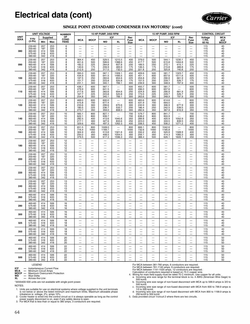
64
SINGLE POINT (STANDARD CONDENSER FAN MOTORS)* (cont)
LEGEND
*30XA400-500 units are not available with single point power.
NOTES:
1. Units are suitable for use on electrical systems where voltage supplied to the unit terminalsis not below or above the listed minimum and maximum limits. Maximum allowable phaseimbalance is: voltage, 2%; amps 10%.
2. Cooler heater is wired into the control circuit so it is always operable as long as the controlpower supply disconnect is on, even if any safety device is open.
3. For MCA that is less than or equal to 380 amps, 3 conductors are required.
For MCA between 381-760 amps, 6 conductors are required.For MCA between 761-1140 amps, 9 conductors are required.For MCA between 1141-1520 amps, 12 conductors are required.Calculation of conductors required is based on 75 C copper wire.
4. Wiring for main field supply must be rated 75 C minimum. Use copper for all units.a. Incoming wire size range for the terminal block is no. 4 AWG (American Wire Gage) to
500 kcmil.b. Incoming wire size range of non-fused disconnect with MCA up to 599.9 amps is 3/0 to
500 kcmil.c. Incoming wire size range of non-fused disconnect with MCA from 600 to 799.9 amps is
1/0 to 500 kcmil.d. Incoming wire size range of non-fused disconnect with MCA from 800 to 1199.9 amps is
250 kcmil to 500 kcmil.5. Data provided circuit 1/circuit 2 where there are two circuits.
UNIT30XA
UNIT VOLTAGE NUMBEROF
CONDFANS
10 HP PUMP, 3450 RPM 15 HP PUMP, 3450 RPM CONTROL CIRCUIT
V-Hz(3 Ph)
Supplied MCA MOCP
ICF RecFuseSize
MCA MOCPICF Rec
FuseSize
Voltage1 PH, 60 Hz
MCA and
MOCPMin Max WD XL WD XL
080
230-60 207 253 6 — — — — — — — — — — 115 40200-60 187 220 6 — — — — — — — — — — 115 40460-60 414 506 6 — — — — — — — — — — 115 40575-60 518 633 6 — — — — — — — — — — 115 40380-60 342 418 6 — — — — — — — — — — 115 40
090
230-60 207 253 8 364.4 450 529.5 1215.5 400 379.0 500 544.1 1230.1 450 115 40200-60 187 220 8 401.6 500 599.6 1388.6 450 417.7 500 615.8 1404.8 500 115 40460-60 414 506 8 182.2 225 264.8 607.8 200 189.5 250 272.1 615.1 225 115 40575-60 518 633 8 140.6 175 209.9 483.9 175 146.5 175 215.8 489.8 175 115 40380-60 342 418 8 212.9 250 317.0 732.0 250 221.8 250 325.8 740.8 250 115 40
100
230-60 207 253 8 395.0 500 567.1 1309.1 450 409.6 500 581.7 1323.7 450 115 40200-60 187 220 8 434.9 500 641.5 1495.5 500 451.1 600 657.6 1511.6 500 115 40460-60 414 506 8 197.5 250 283.6 654.6 225 204.8 250 290.9 661.9 225 115 40575-60 518 633 8 151.7 200 223.8 520.8 175 157.5 200 229.7 526.7 175 115 40380-60 342 418 8 231.1 300 340.1 789.1 300 239.9 300 348.9 797.9 300 115 40
110
230-60 207 253 8 436.1 600 567.1 — 500 450.7 600 581.7 — 500 115 40200-60 187 220 8 479.9 600 641.5 — 600 496.0 600 657.6 — 600 115 40460-60 414 506 8 217.6 300 283.6 654.6 250 224.9 300 290.9 661.9 250 115 40575-60 518 633 8 167.7 225 223.8 520.8 200 173.5 225 229.7 526.7 200 115 40380-60 342 418 8 254.8 350 340.1 789.1 300 263.6 350 348.9 797.9 300 115 40
120
230-60 207 253 8 469.0 600 600.0 — 600 483.6 600 614.6 — 600 115 40200-60 187 220 8 515.8 700 677.4 — 600 531.9 700 693.5 — 600 115 40460-60 414 506 8 233.6 300 299.6 670.6 300 240.9 300 306.9 677.9 300 115 40575-60 518 633 8 180.5 225 236.7 533.7 200 186.4 250 242.5 539.5 225 115 40380-60 342 418 8 273.7 350 359.0 808.0 300 282.6 350 367.9 816.9 350 115 40
140
230-60 207 253 10 565.1 800 827.1 — 700 579.7 800 841.7 — 700 115 40200-60 187 220 10 622.1 800 939.7 — 700 638.2 800 955.9 — 800 115 40460-60 414 506 10 282.5 400 413.6 1045.6 350 289.8 400 420.9 1052.9 350 115 40575-60 518 633 10 217.1 300 327.6 833.6 250 223.0 300 333.5 839.5 250 115 40380-60 342 418 10 329.6 450 497.3 1262.3 400 338.5 450 506.2 1271.2 400 115 40
160
230-60 207 253 10 651.5 800 1028.0 — 800 666.1 800 1042.6 — 800 115 40200-60 187 220 10 716.4 1000 1169.7 — 1000 732.6 1000 1185.8 — 1000 115 40460-60 414 506 10 324.9 450 513.6 1321.6 400 332.2 450 520.9 1328.9 400 115 40575-60 518 633 10 250.2 350 408.5 1054.5 300 256.1 350 414.3 1060.3 300 115 40380-60 342 418 10 379.5 500 617.3 1596.3 450 388.4 500 626.1 1605.1 450 115 40
180
230-60 207 253 12 — — — — — — — — — — 115 40200-60 187 220 12 — — — — — — — — — — 115 40460-60 414 506 12 — — — — — — — — — — 115 40575-60 518 633 12 — — — — — — — — — — 115 40380-60 342 418 12 — — — — — — — — — — 115 40
200
230-60 207 253 12 — — — — — — — — — — 115 40200-60 187 220 12 — — — — — — — — — — 115 40460-60 414 506 12 — — — — — — — — — — 115 40575-60 518 633 12 — — — — — — — — — — 115 40380-60 342 418 12 — — — — — — — — — — 115 40
220
230-60 207 253 13 — — — — — — — — — — 115 40200-60 187 220 13 — — — — — — — — — — 115 40460-60 414 506 13 — — — — — — — — — — 115 40575-60 518 633 13 — — — — — — — — — — 115 40380-60 342 418 13 — — — — — — — — — — 115 40
240
230-60 207 253 13 — — — — — — — — — — 115 40200-60 187 220 13 — — — — — — — — — — 115 40460-60 414 506 13 — — — — — — — — — — 115 40575-60 518 633 13 — — — — — — — — — — 115 40380-60 342 418 13 — — — — — — — — — — 115 40
260460-60 414 506 15 — — — — — — — — — — 115 40575-60 518 633 15 — — — — — — — — — — 115 40380-60 342 418 15 — — — — — — — — — — 115 40
280460-60 414 506 16 — — — — — — — — — — 115 40575-60 518 633 16 — — — — — — — — — — 115 40380-60 342 418 16 — — — — — — — — — — 115 40
300460-60 414 506 16 — — — — — — — — — — 115 40575-60 518 633 16 — — — — — — — — — — 115 40380-60 342 418 16 — — — — — — — — — — 115 40
325460-60 414 506 18 — — — — — — — — — — 115 40575-60 518 633 18 — — — — — — — — — — 115 40380-60 342 418 18 — — — — — — — — — — 115 40
350460-60 414 506 18 — — — — — — — — — — 115 40575-60 518 633 18 — — — — — — — — — — 115 40380-60 342 418 18 — — — — — — — — — — 115 40
400460-60 414 506 20 — — — — — — — — — — 115 50575-60 518 633 20 — — — — — — — — — — 115 50380-60 342 418 20 — — — — — — — — — — 115 50
450460-60 414 506 22 — — — — — — — — — — 115 50575-60 518 633 22 — — — — — — — — — — 115 50380-60 342 418 22 — — — — — — — — — — 115 50
500460-60 414 506 22 — — — — — — — — — — 115 50575-60 518 633 22 — — — — — — — — — — 115 50380-60 342 418 22 — — — — — — — — — — 115 50
ICF — Instantaneous Current FlowMCA — Minimum Circuit AmpsMOCP — Maximum Overcurrent ProtectionWD — Wye-DeltaXL — Across-the-Line
Electrical data (cont)
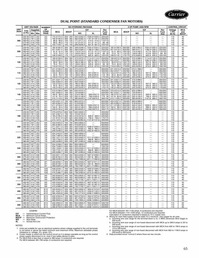
65
DUAL POINT (STANDARD CONDENSER FAN MOTORS)
LEGEND
NOTES:
1. Units are suitable for use on electrical systems where voltage supplied to the unit terminalsis not below or above the listed minimum and maximum limits. Maximum allowable phaseimbalance is: voltage, 2%; amps 10%.
2. Cooler heater is wired into the control circuit so it is always operable as long as the controlpower supply disconnect is on, even if any safety device is open.
3. For MCA that is less than or equal to 380 amps, 3 conductors are required.For MCA between 381-760 amps, 6 conductors are required.
For MCA between 761-1140 amps, 9 conductors are required.For MCA between 1141-1520 amps, 12 conductors are required.Calculation of conductors required is based on 75 C copper wire.
4. Wiring for main field supply must be rated 75 C minimum. Use copper for all units.a. Incoming wire size range for the terminal block is no. 4 AWG (American Wire Gage) to
500 kcmil.b. Incoming wire size range of non-fused disconnect with MCA up to 599.9 amps is 3/0 to
500 kcmil.c. Incoming wire size range of non-fused disconnect with MCA from 600 to 799.9 amps is
1/0 to 500 kcmil.d. Incoming wire size range of non-fused disconnect with MCA from 800 to 1199.9 amps is
250 kcmil to 500 kcmil.5. Data provided circuit 1/circuit 2 where there are two circuits.
UNIT30XA
UNIT VOLTAGE NUMBEROF
CONDFANS
NO HYDRONIC PACKAGE 5 HP PUMP, 3450 RPM CONTROL CIRCUIT
V-Hz(3 Ph)
Supplied MCA MOCP
ICF RecFuseSize
MCA MOCPICF Rec
FuseSize
Voltage1 PH, 60 Hz
MCA and
MOCPMin Max WD XL WD XL
080
230-60 207 253 3/3 173.3/173.3 250/ 250 342.0/342.0 1028.0/1028.0 225/225 — — — — — 115 40200-60 187 220 3/3 190.9/190.9 300/ 300 392.9/392.9 1181.9/1181.9 250/250 — — — — — 115 40460-60 414 506 3/3 86.6/ 86.6 125/ 125 171.0/171.0 514.0/ 514.0 110/110 — — — — — 115 40575-60 518 633 3/3 66.5/ 66.5 110/ 110 137.2/137.2 411.2/ 411.2 80/ 80 — — — — — 115 40380-60 342 418 3/3 100.7/100.7 150/ 150 206.9/206.9 621.9/ 621.9 125/125 — — — — — 115 40
090
230-60 207 253 4/4 182.9/182.9 300/ 300 348.0/348.0 1034.0/1034.0 225/225 182.9/198.9 300/300 348.0/364.0 1034.0/1050.0 225/250 115 40200-60 187 220 4/4 201.5/201.5 300/ 300 399.5/399.5 1188.5/1188.5 250/250 201.5/219.2 300/350 399.5/417.2 1188.5/1206.2 250/300 115 40460-60 414 506 4/4 91.4/ 91.4 150/ 150 174.0/174.0 517.0/ 517.0 110/110 91.4/ 99.4 150/150 174.0/182.0 517.0/ 525.0 110/125 115 40575-60 518 633 4/4 70.3/ 70.3 110/ 110 139.6/139.6 413.6/ 413.6 90/ 90 70.3/ 76.7 110/125 139.6/146.0 413.6/ 420.0 90/ 90 115 40380-60 342 418 4/4 106.5/106.5 175/ 175 210.5/210.5 625.5/ 625.5 125/125 106.5/116.1 175/175 210.5/220.2 625.5/ 635.2 125/150 115 40
100
230-60 207 253 4/4 199.9/199.9 300/ 300 372.0/372.0 1114.0/1114.0 250/250 199.9/215.9 300/350 372.0/388.0 1114.0/1130.0 250/300 115 40200-60 187 220 4/4 220.0/220.0 350/ 350 426.5/426.5 1280.5/1280.5 300/300 220.0/237.7 350/350 426.5/444.2 1280.5/1298.2 300/300 115 40460-60 414 506 4/4 99.9/ 99.9 150/ 150 186.0/186.0 557.0/ 557.0 125/125 99.9/107.9 150/175 186.0/194.0 557.0/ 565.0 125/150 115 40575-60 518 633 4/4 76.4/ 76.4 125/ 125 148.6/148.6 445.6/ 445.6 90/ 90 76.4/ 82.8 125/125 148.6/155.0 445.6/ 452.0 90/100 115 40380-60 342 418 4/4 116.5/116.5 175/ 175 225.5/225.5 674.5/ 674.5 150/150 116.5/126.2 175/200 225.5/235.2 674.5/ 684.2 150/150 115 40
110
230-60 207 253 4/4 241.0/199.9 400/ 300 372.0/372.0 — 300/250 241.0/215.9 400/350 372.0 /388.0 — 300/300 115 40200-60 187 220 4/4 264.9/220.0 450/ 350 426.5/426.5 — 350/300 264.9/237.7 450/350 426.5/444.2 — 350/300 115 40460-60 414 506 4/4 120.0/ 99.9 200/ 150 186.0/186.0 557.0/557.0 150/125 120.0/107.9 200/175 186.0/194.0 557.0/ 565.0 150/150 115 40575-60 518 633 4/4 92.5/ 76.4 150/ 125 148.6/148.6 445.6/445.6 110/ 90 92.5/ 82.8 150/125 148.6/155.0 445.6/ 452.0 110/100 115 40380-60 342 418 4/4 140.2/116.5 225/ 175 225.5/225.5 674.5/674.5 175/150 140.2/126.2 225/200 225.5/235.2 674.5/ 684.2 175/150 115 40
120
230-60 207 253 4/4 241.0/241.0 400/ 400 372.0/372.0 — 300/300 241.0/257.0 400/400 372.0/388.0 — 300/350 115 40200-60 187 220 4/4 264.9/264.9 450/ 450 426.5/426.5 — 350/350 264.9/282.6 450/450 426.5/444.2 — 350/350 115 40460-60 414 506 4/4 120.0/120.0 200/ 200 186.0/186.0 557.0/557.0 150/150 120.0/128.0 200/200 186.0/194.0 557.0/ 565.0 150/150 115 40575-60 518 633 4/4 92.5/ 92.5 150/ 150 148.6/148.6 445.6/445.6 110/110 92.5/ 98.9 150/150 148.6/155.0 445.6/ 452.0 110/125 115 40380-60 342 418 4/4 140.2/140.2 225/ 225 225.5/225.5 674.5/674.5 175/175 140.2/149.9 225/250 225.5/235.2 674.5/ 684.2 175/200 115 40
140
230-60 207 253 6/4 370.0/199.9 600/ 300 632.0/372.0 — 450/250 370.0/215.9 600/350 632.0/388.0 — 450/300 115 40200-60 187 220 6/4 407.2/220.0 700/ 350 724.8/426.5 — 500/300 407.2/237.7 700/350 724.8/444.2 — 500/300 115 40460-60 414 506 6/4 185.0/ 99.9 300/ 150 316.0/186.0 948.0/557.0 225/125 185.0/107.9 300/175 316.0/194.0 948.0/ 565.0 225/150 115 40575-60 518 633 6/4 141.9/ 76.4 225/ 125 252.4/148.6 758.4/445.6 175/ 90 141.9/ 82.8 225/125 252.4/155.0 758.4/ 452.0 175/100 115 40380-60 342 418 6/4 215.1/116.5 350/ 175 382.8/225.5 1147.8/674.5 300/150 215.1/126.2 350/200 382.8/235.2 1147.8/ 684.2 300/150 115 40
160
230-60 207 253 6/4 423.5/241.0 700/ 400 800.0/372.0 — 600/300 423.5/257.0 700/400 800.0/388.0 — 600/350 115 40200-60 187 220 6/4 465.6/264.9 800/ 450 918.8/426.5 — 600/350 465.6/282.6 800/450 918.8/444.2 — 600/350 115 40460-60 414 506 6/4 211.3/120.0 350/ 200 400.0/186.0 1208.0/557.0 250/150 211.3/128.0 350/200 400.0/194.0 1208.0/ 565.0 250/150 115 40575-60 518 633 6/4 162.2/ 92.5 250/ 150 320.4/148.6 966.4/445.6 200/110 162.2/ 98.9 250/150 320.4/155.0 966.4/ 452.0 200/125 115 40380-60 342 418 6/4 246.0/140.2 400/ 225 483.8/225.5 1462.8/674.5 300/175 246.0/149.9 400/250 483.8/235.2 1462.8/ 684.2 300/200 115 40
180
230-60 207 253 6/6 370.0/370.0 600/ 600 632.0/632.0 — 450/450 — — — — — 115 40200-60 187 220 6/6 407.2/407.2 700/ 700 724.8/724.8 — 500/500 — — — — — 115 40460-60 414 506 6/6 185.0/185.0 300/ 300 316.0/316.0 948.0/ 948.0 225/225 — — — — — 115 40575-60 518 633 6/6 141.9/141.9 225/ 225 252.4/252.4 758.4/ 758.4 175/175 — — — — — 115 40380-60 342 418 6/6 215.1/215.1 350/ 350 382.8/382.8 1147.8/1147.8 300/300 — — — — — 115 40
200
230-60 207 253 6/6 423.5/423.5 700/ 700 800.0/800.0 — 600/600 — — — — — 115 40200-60 187 220 6/6 465.6/465.6 800/ 800 918.8/918.8 — 600/600 — — — — — 115 40460-60 414 506 6/6 211.3/211.3 350/ 350 400.0/400.0 1208.0/1208.0 250/250 — — — — — 115 40575-60 518 633 6/6 162.2/162.2 250/ 250 320.4/320.4 966.4/ 966.4 200/200 — — — — — 115 40380-60 342 418 6/6 246.0/246.0 400/ 400 483.8/483.8 1462.8/1462.8 300/300 — — — — — 115 40
220
230-60 207 253 7/6 504.2/423.5 800/ 700 806.0/800.0 — 600/600 — — — — — 115 40200-60 187 220 7/6 554.7/465.6 800/ 800 925.4/918.8 — 700/600 — — — — — 115 40460-60 414 506 7/6 252.1/211.3 400/ 350 403.0/400.0 1211.0/1208.0 300/250 — — — — — 115 40575-60 518 633 7/6 193.7/162.2 300/ 250 322.8/320.4 968.8/ 966.4 250/200 — — — — — 115 40380-60 342 418 7/6 293.3/246.0 500/ 400 487.4/483.8 1466.4/1462.8 350/300 — — — — — 115 40
240
230-60 207 253 7/6 504.2/498.2 800/ 800 806.0/800.0 — 600/600 — — — — — 115 40200-60 187 220 7/6 554.7/548.0 800/ 800 925.4/918.8 — 700/700 — — — — — 115 40460-60 414 506 7/6 252.1/249.1 400/ 400 403.0/400.0 1211.0/1208.0 300/300 — — — — — 115 40575-60 518 633 7/6 193.7/191.3 300/ 300 322.8/320.4 968.8/ 966.4 250/250 — — — — — 115 40380-60 342 418 7/6 293.3/289.7 500/ 500 487.4/483.8 1466.4/1462.8 350/350 — — — — — 115 40
260460-60 414 506 9/6 343.9/211.3 500/ 350 605.0/400.0 1827.0/1208.0 450/250 — — — — — 115 40575-60 518 633 9/6 263.8/162.2 450/ 250 483.6/320.4 1461.6/ 966.4 350/200 — — — — — 115 40380-60 342 418 9/6 399.0/246.0 600/ 400 732.7/483.8 2211.7/1462.8 500/300 — — — — — 115 40
280460-60 414 506 9/7 343.9/252.1 500/ 400 605.0/403.0 1827.0/1211.0 450/300 — — — — — 115 40575-60 518 633 9/7 263.8/193.7 450/ 300 483.6/322.8 1461.6/ 968.8 350/250 — — — — — 115 40380-60 342 418 9/7 399.0/293.3 600/ 500 732.7/487.4 2211.7/1466.4 500/350 — — — — — 115 40
300460-60 414 506 10/6 408.0/249.1 700/ 400 608.0/400.0 1830.0/1208.0 500/300 — — — — — 115 40575-60 518 633 10/6 312.8/191.3 500/ 300 486.0/320.4 1464.0/ 966.4 400/250 — — — — — 115 40380-60 342 418 10/6 474.2/289.7 800/ 500 736.3/483.8 2215.3/1462.8 600/350 — — — — — 115 40
325460-60 414 506 9/9 343.9/343.9 500/ 500 605.0/605.0 1827.0/1827.0 450/450 — — — — — 115 40575-60 518 633 9/9 263.8/263.8 450/ 450 483.6/483.6 1461.6/1461.6 350/350 — — — — — 115 40380-60 342 418 9/9 399.0/399.0 600/ 600 732.7/732.7 2211.7/2211.7 500/500 — — — — — 115 40
350460-60 414 506 9/9 405.0/343.9 700/ 500 605.0/605.0 1827.0/1827.0 500/450 — — — — — 115 40575-60 518 633 9/9 310.4/263.8 500/ 450 483.6/483.6 1461.6/1461.6 400/350 — — — — — 115 40380-60 342 418 9/9 470.5/399.0 800/ 600 732.7/732.7 2211.7/2211.7 600/500 — — — — — 115 40
400460-60 414 506 8/12 340.9/452.0 500/ 600 602.0/602.9 1824.0/1410.9 450/500 — — — — — 115 50575-60 518 633 8/12 261.4/347.2 450/ 450 481.2/476.3 1459.2/1122.3 350/400 — — — — — 115 50380-60 342 418 8/12 395.4/525.8 600/ 700 729.1/719.9 2208.1/1698.9 500/600 — — — — — 115 50
450460-60 414 506 8/14 402.0/553.6 700/ 800 602.0/753.6 1824.0/1975.6 500/700 — — — — — 115 50575-60 518 633 8/14 308.0/424.4 500/ 600 481.2/597.6 1459.2/1575.6 400/500 — — — — — 115 50380-60 342 418 8/14 466.9/643.3 800/ 800 729.1/905.5 2208.1/2384.5 600/800 — — — — — 115 50
500460-60 414 506 8/14 402.0/604.9 700/ 800 602.0/804.9 1824.0/2026.9 500/700 — — — — — 115 50575-60 518 633 8/14 308.0/463.9 500/ 600 481.2/637.1 1459.2/1615.1 400/600 — — — — — 115 50380-60 342 418 8/14 466.9/703.0 800/1000 729.1/965.2 2208.1/2444.2 600/800 — — — — — 115 50
ICF — Instantaneous Current FlowMCA — Minimum Circuit AmpsMOCP — Maximum Overcurrent ProtectionWD — Wye-DeltaXL — Across-the-Line
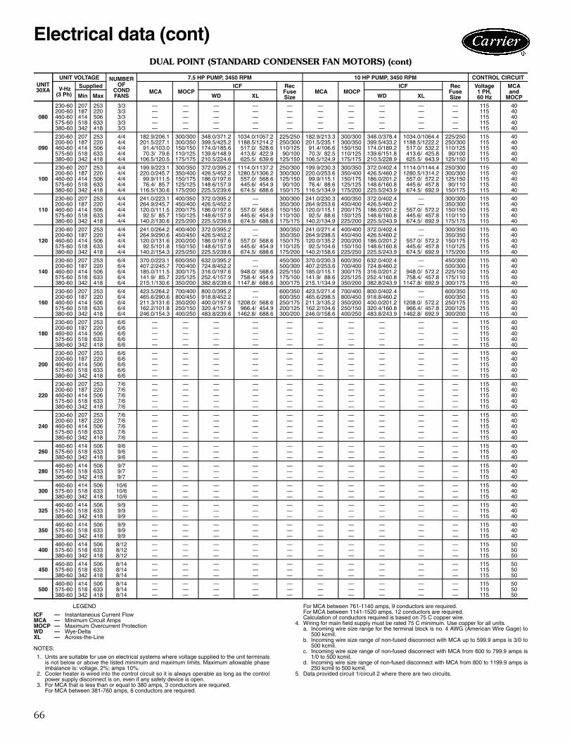
66
DUAL POINT (STANDARD CONDENSER FAN MOTORS) (cont)
LEGEND
NOTES:
1. Units are suitable for use on electrical systems where voltage supplied to the unit terminalsis not below or above the listed minimum and maximum limits. Maximum allowable phaseimbalance is: voltage, 2%; amps 10%.
2. Cooler heater is wired into the control circuit so it is always operable as long as the controlpower supply disconnect is on, even if any safety device is open.
3. For MCA that is less than or equal to 380 amps, 3 conductors are required.For MCA between 381-760 amps, 6 conductors are required.
For MCA between 761-1140 amps, 9 conductors are required.For MCA between 1141-1520 amps, 12 conductors are required.Calculation of conductors required is based on 75 C copper wire.
4. Wiring for main field supply must be rated 75 C minimum. Use copper for all units.a. Incoming wire size range for the terminal block is no. 4 AWG (American Wire Gage) to
500 kcmil.b. Incoming wire size range of non-fused disconnect with MCA up to 599.9 amps is 3/0 to
500 kcmil.c. Incoming wire size range of non-fused disconnect with MCA from 600 to 799.9 amps is
1/0 to 500 kcmil.d. Incoming wire size range of non-fused disconnect with MCA from 800 to 1199.9 amps is
250 kcmil to 500 kcmil.5. Data provided circuit 1/circuit 2 where there are two circuits.
UNIT30XA
UNIT VOLTAGE NUMBEROF
CONDFANS
7.5 HP PUMP, 3450 RPM 10 HP PUMP, 3450 RPM CONTROL CIRCUIT
V-Hz(3 Ph)
Supplied MCA MOCP
ICF RecFuseSize
MCA MOCPICF Rec
FuseSize
Voltage1 PH, 60 Hz
MCA and
MOCPMin Max WD XL WD XL
080
230-60 207 253 3/3 — — — — — — — — — — 115 40200-60 187 220 3/3 — — — — — — — — — — 115 40460-60 414 506 3/3 — — — — — — — — — — 115 40575-60 518 633 3/3 — — — — — — — — — — 115 40380-60 342 418 3/3 — — — — — — — — — — 115 40
090
230-60 207 253 4/4 182.9/206.1 300/300 348.0/371.2 1034.0/1057.2 225/250 182.9/213.3 300/300 348.0/378.4 1034.0/1064.4 225/250 115 40200-60 187 220 4/4 201.5/227.1 300/350 399.5/425.2 1188.5/1214.2 250/300 201.5/235.1 300/350 399.5/433.2 1188.5/1222.2 250/300 115 40460-60 414 506 4/4 91.4/103.0 150/150 174.0/185.6 517.0/ 528.6 110/125 91.4/106.6 150/150 174.0/189.2 517.0/ 532.2 110/125 115 40575-60 518 633 4/4 70.3/ 79.6 110/125 139.6/148.9 413.6/ 422.9 90/100 70.3/ 82.5 110/125 139.6/151.8 413.6/ 425.8 90/100 115 40380-60 342 418 4/4 106.5/120.5 175/175 210.5/224.6 625.5/ 639.6 125/150 106.5/124.9 175/175 210.5/228.9 625.5/ 643.9 125/150 115 40
100
230-60 207 253 4/4 199.9/223.1 300/350 372.0/395.2 1114.0/1137.2 250/300 199.9/230.3 300/350 372.0/402.4 1114.0/1144.4 250/300 115 40200-60 187 220 4/4 220.0/245.7 350/400 426.5/452.2 1280.5/1306.2 300/300 220.0/253.6 350/400 426.5/460.2 1280.5/1314.2 300/300 115 40460-60 414 506 4/4 99.9/111.5 150/175 186.0/197.6 557.0/ 568.6 125/150 99.9/115.1 150/175 186.0/201.2 557.0/ 572.2 125/150 115 40575-60 518 633 4/4 76.4/ 85.7 125/125 148.6/157.9 445.6/ 454.9 90/100 76.4/ 88.6 125/125 148.6/160.8 445.6/ 457.8 90/110 115 40380-60 342 418 4/4 116.5/130.6 175/200 225.5/239.6 674.5/ 688.6 150/175 116.5/134.9 175/200 225.5/243.9 674.5/ 692.9 150/175 115 40
110
230-60 207 253 4/4 241.0/223.1 400/350 372.0/395.2 — 300/300 241.0/230.3 400/350 372.0/402.4 — 300/300 115 40200-60 187 220 4/4 264.9/245.7 450/400 426.5/452.2 — 350/300 264.9/253.6 450/400 426.5/460.2 — 350/300 115 40460-60 414 506 4/4 120.0/111.5 200/175 186.0/197.6 557.0/ 568.6 150/150 120.0/115.1 200/175 186.0/201.2 557.0/ 572.2 150/150 115 40575-60 518 633 4/4 92.5/ 85.7 150/125 148.6/157.9 445.6/ 454.9 110/100 92.5/ 88.6 150/125 148.6/160.8 445.6/ 457.8 110/110 115 40380-60 342 418 4/4 140.2/130.6 225/200 225.5/239.6 674.5/ 688.6 175/175 140.2/134.9 225/200 225.5/243.9 674.5/ 692.9 175/175 115 40
120
230-60 207 253 4/4 241.0/264.2 400/400 372.0/395.2 — 300/350 241.0/271.4 400/400 372.0/402.4 — 300/350 115 40200-60 187 220 4/4 264.9/290.6 450/450 426.5/452.2 — 350/350 264.9/298.5 450/450 426.5/460.2 — 350/350 115 40460-60 414 506 4/4 120.0/131.6 200/200 186.0/197.6 557.0/ 568.6 150/175 120.0/135.2 200/200 186.0/201.2 557.0/ 572.2 150/175 115 40575-60 518 633 4/4 92.5/101.8 150/150 148.6/157.9 445.6/ 454.9 110/125 92.5/104.6 150/150 148.6/160.8 445.6/ 457.8 110/125 115 40380-60 342 418 4/4 140.2/154.3 225/250 225.5/239.6 674.5/ 688.6 175/200 140.2/158.6 225/250 225.5/243.9 674.5/ 692.9 175/200 115 40
140
230-60 207 253 6/4 370.0/223.1 600/350 632.0/395.2 — 450/300 370.0/230.3 600/350 632.0/402.4 — 450/300 115 40200-60 187 220 6/4 407.2/245.7 700/400 724.8/452.2 — 500/300 407.2/253.6 700/400 724.8/460.2 — 500/300 115 40460-60 414 506 6/4 185.0/111.5 300/175 316.0/197.6 948.0/ 568.6 225/150 185.0/115.1 300/175 316.0/201.2 948.0/ 572.2 225/150 115 40575-60 518 633 6/4 141.9/ 85.7 225/125 252.4/157.9 758.4/ 454.9 175/100 141.9/ 88.6 225/125 252.4/160.8 758.4/ 457.8 175/110 115 40380-60 342 418 6/4 215.1/130.6 350/200 382.8/239.6 1147.8/ 688.6 300/175 215.1/134.9 350/200 382.8/243.9 1147.8/ 692.9 300/175 115 40
160
230-60 207 253 6/4 423.5/264.2 700/400 800.0/395.2 — 600/350 423.5/271.4 700/400 800.0/402.4 — 600/350 115 40200-60 187 220 6/4 465.6/290.6 800/450 918.8/452.2 — 600/350 465.6/298.5 800/450 918.8/460.2 — 600/350 115 40460-60 414 506 6/4 211.3/131.6 350/200 400.0/197.6 1208.0/ 568.6 250/175 211.3/135.2 350/200 400.0/201.2 1208.0/ 572.2 250/175 115 40575-60 518 633 6/4 162.2/101.8 250/150 320.4/157.9 966.4/ 454.9 200/125 162.2/104.6 250/150 320.4/160.8 966.4/ 457.8 200/125 115 40380-60 342 418 6/4 246.0/154.3 400/250 483.8/239.6 1462.8/ 688.6 300/200 246.0/158.6 400/250 483.8/243.9 1462.8/ 692.9 300/200 115 40
180
230-60 207 253 6/6 — — — — — — — — — — 115 40200-60 187 220 6/6 — — — — — — — — — — 115 40460-60 414 506 6/6 — — — — — — — — — — 115 40575-60 518 633 6/6 — — — — — — — — — — 115 40380-60 342 418 6/6 — — — — — — — — — — 115 40
200
230-60 207 253 6/6 — — — — — — — — — — 115 40200-60 187 220 6/6 — — — — — — — — — — 115 40460-60 414 506 6/6 — — — — — — — — — — 115 40575-60 518 633 6/6 — — — — — — — — — — 115 40380-60 342 418 6/6 — — — — — — — — — — 115 40
220
230-60 207 253 7/6 — — — — — — — — — — 115 40200-60 187 220 7/6 — — — — — — — — — — 115 40460-60 414 506 7/6 — — — — — — — — — — 115 40575-60 518 633 7/6 — — — — — — — — — — 115 40380-60 342 418 7/6 — — — — — — — — — — 115 40
240
230-60 207 253 7/6 — — — — — — — — — — 115 40200-60 187 220 7/6 — — — — — — — — — — 115 40460-60 414 506 7/6 — — — — — — — — — — 115 40575-60 518 633 7/6 — — — — — — — — — — 115 40380-60 342 418 7/6 — — — — — — — — — — 115 40
260460-60 414 506 9/6 — — — — — — — — — — 115 40575-60 518 633 9/6 — — — — — — — — — — 115 40380-60 342 418 9/6 — — — — — — — — — — 115 40
280460-60 414 506 9/7 — — — — — — — — — — 115 40575-60 518 633 9/7 — — — — — — — — — — 115 40380-60 342 418 9/7 — — — — — — — — — — 115 40
300460-60 414 506 10/6 — — — — — — — — — — 115 40575-60 518 633 10/6 — — — — — — — — — — 115 40380-60 342 418 10/6 — — — — — — — — — — 115 40
325460-60 414 506 9/9 — — — — — — — — — — 115 40575-60 518 633 9/9 — — — — — — — — — — 115 40380-60 342 418 9/9 — — — — — — — — — — 115 40
350460-60 414 506 9/9 — — — — — — — — — — 115 40575-60 518 633 9/9 — — — — — — — — — — 115 40380-60 342 418 9/9 — — — — — — — — — — 115 40
400460-60 414 506 8/12 — — — — — — — — — — 115 50575-60 518 633 8/12 — — — — — — — — — — 115 50380-60 342 418 8/12 — — — — — — — — — — 115 50
450460-60 414 506 8/14 — — — — — — — — — — 115 50575-60 518 633 8/14 — — — — — — — — — — 115 50380-60 342 418 8/14 — — — — — — — — — — 115 50
500460-60 414 506 8/14 — — — — — — — — — — 115 50575-60 518 633 8/14 — — — — — — — — — — 115 50380-60 342 418 8/14 — — — — — — — — — — 115 50
ICF — Instantaneous Current FlowMCA — Minimum Circuit AmpsMOCP — Maximum Overcurrent ProtectionWD — Wye-DeltaXL — Across-the-Line
Electrical data (cont)
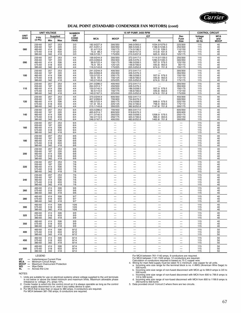
67
DUAL POINT (STANDARD CONDENSER FAN MOTORS) (cont)
LEGEND
NOTES:
1. Units are suitable for use on electrical systems where voltage supplied to the unit terminalsis not below or above the listed minimum and maximum limits. Maximum allowable phaseimbalance is: voltage, 2%; amps 10%.
2. Cooler heater is wired into the control circuit so it is always operable as long as the controlpower supply disconnect is on, even if any safety device is open.
3. For MCA that is less than or equal to 380 amps, 3 conductors are required.For MCA between 381-760 amps, 6 conductors are required.
For MCA between 761-1140 amps, 9 conductors are required.For MCA between 1141-1520 amps, 12 conductors are required.Calculation of conductors required is based on 75 C copper wire.
4. Wiring for main field supply must be rated 75 C minimum. Use copper for all units.a. Incoming wire size range for the terminal block is no. 4 AWG (American Wire Gage) to
500 kcmil.b. Incoming wire size range of non-fused disconnect with MCA up to 599.9 amps is 3/0 to
500 kcmil.c. Incoming wire size range of non-fused disconnect with MCA from 600 to 799.9 amps is
1/0 to 500 kcmil.d. Incoming wire size range of non-fused disconnect with MCA from 800 to 1199.9 amps is
250 kcmil to 500 kcmil.5. Data provided circuit 1/circuit 2 where there are two circuits.
UNIT30XA
UNIT VOLTAGE NUMBEROF
CONDFANS
15 HP PUMP, 3450 RPM CONTROL CIRCUIT
V-Hz(3 Ph)
Supplied MCA MOCP
ICF RecFuseSize
Voltage1 PH, 60 Hz
MCA and
MOCPMin Max WD XL
080
230-60 207 253 3/3 182.9/227.9 300/350 348.0/393.0 1034.0/1079.0 225/300 115 40200-60 187 220 3/3 201.5/251.2 300/350 399.5/449.3 1188.5/1238.3 250/300 115 40460-60 414 506 3/3 91.4/113.9 150/175 174.0/196.5 517.0/ 539.5 110/150 115 40575-60 518 633 3/3 70.3/ 88.3 110/125 139.6/157.6 413.6/ 431.6 90/110 115 40380-60 342 418 3/3 106.5/133.7 175/200 210.5/237.8 625.5/ 652.8 125/175 115 40
090
230-60 207 253 4/4 199.9/244.9 300/350 372.0/417.0 1114.0/1159.0 250/300 115 40200-60 187 220 4/4 220.0/269.8 350/400 426.5/476.3 1280.5/1330.3 300/350 115 40460-60 414 506 4/4 99.9/122.4 150/175 186.0/208.5 557.0/ 579.5 125/150 115 40575-60 518 633 4/4 76.4/ 94.4 125/125 148.6/166.6 445.6/ 463.6 90/110 115 40380-60 342 418 4/4 116.5/143.8 175/225 225.5/252.8 674.5/ 701.8 150/175 115 40
100
230-60 207 253 4/4 241.0/244.9 400/350 372.0/417.0 — 300/300 115 40200-60 187 220 4/4 264.9/269.8 450/400 426.5/476.3 — 350/350 115 40460-60 414 506 4/4 120.0/122.4 200/175 186.0/208.5 557.0/ 579.5 150/150 115 40575-60 518 633 4/4 92.5/ 94.4 150/125 148.6/166.6 445.6/ 463.6 110/110 115 40380-60 342 418 4/4 140.2/143.8 225/225 225.5/252.8 674.5/ 701.8 175/175 115 40
110
230-60 207 253 4/4 241.0/286.0 400/450 372.0/417.0 — 300/350 115 40200-60 187 220 4/4 264.9/314.7 450/500 426.5/476.3 — 350/400 115 40460-60 414 506 4/4 120.0/142.5 200/225 186.0/208.5 557.0/ 579.5 150/175 115 40575-60 518 633 4/4 92.5/110.5 150/175 148.6/166.6 445.6/ 463.6 110/150 115 40380-60 342 418 4/4 140.2/167.5 225/250 225.5/252.8 674.5/ 701.8 175/200 115 40
120
230-60 207 253 4/4 370.0/244.9 600/350 632.0/417.0 — 450/300 115 40200-60 187 220 4/4 407.2/269.8 700/400 724.8/476.3 — 500/350 115 40460-60 414 506 4/4 185.0/122.4 300/175 316.0/208.5 948.0/ 579.5 225/150 115 40575-60 518 633 4/4 141.9/ 94.4 225/125 252.4/166.6 758.4/ 463.6 175/110 115 40380-60 342 418 4/4 215.1/143.8 350/225 382.8/252.8 1147.8/ 701.8 300/175 115 40
140
230-60 207 253 6/4 423.5/286.0 700/450 800.0/417.0 — 600/350 115 40200-60 187 220 6/4 465.6/314.7 800/500 918.8/476.3 — 600/400 115 40460-60 414 506 6/4 211.3/142.5 350/225 400.0/208.5 1208.0/ 579.5 250/175 115 40575-60 518 633 6/4 162.2/110.5 250/175 320.4/166.6 966.4/ 463.6 200/150 115 40380-60 342 418 6/4 246.0/167.5 400/250 483.8/252.8 1462.8/ 701.8 300/200 115 40
160
230-60 207 253 6/4 — — — — — 115 40200-60 187 220 6/4 — — — — — 115 40460-60 414 506 6/4 — — — — — 115 40575-60 518 633 6/4 — — — — — 115 40380-60 342 418 6/4 — — — — — 115 40
180
230-60 207 253 6/6 — — — — — 115 40200-60 187 220 6/6 — — — — — 115 40460-60 414 506 6/6 — — — — — 115 40575-60 518 633 6/6 — — — — — 115 40380-60 342 418 6/6 — — — — — 115 40
200
230-60 207 253 6/6 — — — — — 115 40200-60 187 220 6/6 — — — — — 115 40460-60 414 506 6/6 — — — — — 115 40575-60 518 633 6/6 — — — — — 115 40380-60 342 418 6/6 — — — — — 115 40
220
230-60 207 253 7/6 — — — — — 115 40200-60 187 220 7/6 — — — — — 115 40460-60 414 506 7/6 — — — — — 115 40575-60 518 633 7/6 — — — — — 115 40380-60 342 418 7/6 — — — — — 115 40
240
230-60 207 253 7/6 — — — — — 115 40200-60 187 220 7/6 — — — — — 115 40460-60 414 506 7/6 — — — — — 115 40575-60 518 633 7/6 — — — — — 115 40380-60 342 418 7/6 — — — — — 115 40
260460-60 414 506 9/6 — — — — — 115 40575-60 518 633 9/6 — — — — — 115 40380-60 342 418 9/6 — — — — — 115 40
280460-60 414 506 9/7 — — — — — 115 40575-60 518 633 9/7 — — — — — 115 40380-60 342 418 9/7 — — — — — 115 40
300460-60 414 506 10/6 — — — — — 115 40575-60 518 633 10/6 — — — — — 115 40380-60 342 418 10/6 — — — — — 115 40
325460-60 414 506 9/9 — — — — — 115 40575-60 518 633 9/9 — — — — — 115 40380-60 342 418 9/9 — — — — — 115 40
350460-60 414 506 9/9 — — — — — 115 40575-60 518 633 9/9 — — — — — 115 40380-60 342 418 9/9 — — — — — 115 40
400460-60 414 506 8/12 — — — — — 115 50575-60 518 633 8/12 — — — — — 115 50380-60 342 418 8/12 — — — — — 115 50
450460-60 414 506 8/14 — — — — — 115 50575-60 518 633 8/14 — — — — — 115 50380-60 342 418 8/14 — — — — — 115 50
500460-60 414 506 8/14 — — — — — 115 50575-60 518 633 8/14 — — — — — 115 50380-60 342 418 8/14 — — — — — 115 50
ICF — Instantaneous Current FlowMCA — Minimum Circuit AmpsMOCP — Maximum Overcurrent ProtectionWD — Wye-DeltaXL — Across-the-Line
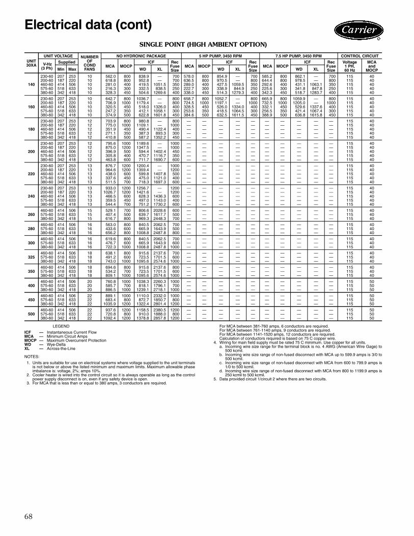
68
SINGLE POINT (HIGH AMBIENT OPTION)
LEGEND
NOTES:
1. Units are suitable for use on electrical systems where voltage supplied to the unit terminalsis not below or above the listed minimum and maximum limits. Maximum allowable phaseimbalance is: voltage, 2%; amps 10%.
2. Cooler heater is wired into the control circuit so it is always operable as long as the controlpower supply disconnect is on, even if any safety device is open.
3. For MCA that is less than or equal to 380 amps, 3 conductors are required.
For MCA between 381-760 amps, 6 conductors are required.For MCA between 761-1140 amps, 9 conductors are required.For MCA between 1141-1520 amps, 12 conductors are required.Calculation of conductors required is based on 75 C copper wire.
4. Wiring for main field supply must be rated 75 C minimum. Use copper for all units.a. Incoming wire size range for the terminal block is no. 4 AWG (American Wire Gage) to
500 kcmil.b. Incoming wire size range of non-fused disconnect with MCA up to 599.9 amps is 3/0 to
500 kcmil.c. Incoming wire size range of non-fused disconnect with MCA from 600 to 799.9 amps is
1/0 to 500 kcmil.d. Incoming wire size range of non-fused disconnect with MCA from 800 to 1199.9 amps is
250 kcmil to 500 kcmil.5. Data provided circuit 1/circuit 2 where there are two circuits.
UNIT30XA
UNIT VOLTAGE NUMBEROF
CONDFANS
NO HYDRONIC PACKAGE 5 HP PUMP, 3450 RPM 7.5 HP PUMP, 3450 RPM CONTROL CIRCUIT
V-Hz(3 Ph)
Supplied MCA MOCP
ICF RecFuseSize
MCA MOCPICF Rec
FuseSize
MCA MOCPICF Rec
FuseSize
Voltage1 PH, 60 Hz
MCA and
MOCPMin Max WD XL WD XL WD XL
140
230-60 207 253 10 562.0 800 838.9 — 700 578.0 800 854.9 — 700 585.2 800 862.1 — 700 115 40200-60 187 220 10 618.8 800 952.8 — 700 636.5 800 970.5 — 800 644.4 800 978.5 — 800 115 40460-60 414 506 10 281.0 400 419.5 1051.5 350 289.0 400 427.5 1059.5 350 292.6 400 431.1 1063.1 350 115 40575-60 518 633 10 216.3 300 332.5 838.5 250 222.7 300 338.9 844.9 250 225.6 300 341.8 847.8 250 115 40380-60 342 418 10 328.3 450 504.6 1269.6 400 338.0 450 514.3 1279.3 400 342.3 450 518.7 1283.7 400 115 40
160
230-60 207 253 10 642.7 800 1036.7 — 800 658.7 800 1052.7 — 800 665.9 800 1059.9 — 800 115 40200-60 187 220 10 706.9 1000 1179.4 — 800 724.5 1000 1197.1 — 1000 732.5 1000 1205.0 — 1000 115 40460-60 414 506 10 320.5 450 518.0 1326.0 400 328.5 450 526.0 1334.0 400 332.1 450 529.6 1337.6 400 115 40575-60 518 633 10 247.2 350 412.1 1058.1 300 253.6 350 418.5 1064.5 300 256.5 350 421.4 1067.4 300 115 40380-60 342 418 10 374.9 500 622.8 1601.8 450 384.6 500 632.5 1611.5 450 388.9 500 636.8 1615.8 450 115 40
180
230-60 207 253 12 703.9 800 980.8 — 800 — — — — — — — — — — 115 40200-60 187 220 12 775.0 1000 1109.1 — 1000 — — — — — — — — — — 115 40460-60 414 506 12 351.9 450 490.4 1122.4 400 — — — — — — — — — — 115 40575-60 518 633 12 271.1 350 387.3 893.3 300 — — — — — — — — — — 115 40380-60 342 418 12 410.8 500 587.2 1352.2 450 — — — — — — — — — — 115 40
200
230-60 207 253 12 795.6 1000 1189.6 — 1000 — — — — — — — — — — 115 40200-60 187 220 12 875.0 1200 1347.5 — 1000 — — — — — — — — — — 115 40460-60 414 506 12 396.9 500 594.4 1402.4 450 — — — — — — — — — — 115 40575-60 518 633 12 305.8 400 470.7 1116.7 350 — — — — — — — — — — 115 40380-60 342 418 12 463.8 600 711.7 1690.7 600 — — — — — — — — — — 115 40
220
230-60 207 253 13 876.7 1200 1200.4 — 1000 — — — — — — — — — — 115 40200-60 187 220 13 964.6 1200 1359.4 — 1200 — — — — — — — — — — 115 40460-60 414 506 13 438.0 600 599.8 1407.8 500 — — — — — — — — — — 115 40575-60 518 633 13 337.6 450 475.0 1121.0 400 — — — — — — — — — — 115 40380-60 342 418 13 511.5 700 718.3 1697.3 600 — — — — — — — — — — 115 40
240
230-60 207 253 13 933.0 1200 1256.7 — 1200 — — — — — — — — — — 115 40200-60 187 220 13 1026.7 1200 1421.6 — 1200 — — — — — — — — — — 115 40460-60 414 506 13 466.5 600 628.3 1436.3 600 — — — — — — — — — — 115 40575-60 518 633 13 359.5 450 497.0 1143.0 400 — — — — — — — — — — 115 40380-60 342 418 13 544.4 700 751.2 1730.2 600 — — — — — — — — — — 115 40
260460-60 414 506 15 529.1 700 806.6 2028.6 600 — — — — — — — — — — 115 40575-60 518 633 15 407.4 500 639.7 1617.7 500 — — — — — — — — — — 115 40380-60 342 418 15 616.7 800 969.3 2448.3 700 — — — — — — — — — — 115 40
280460-60 414 506 16 563.0 800 840.5 2062.5 700 — — — — — — — — — — 115 40575-60 518 633 16 433.6 600 665.9 1643.9 500 — — — — — — — — — — 115 40380-60 342 418 16 656.2 800 1008.8 2487.8 800 — — — — — — — — — — 115 40
300460-60 414 506 16 619.6 800 840.5 2062.5 700 — — — — — — — — — — 115 40575-60 518 633 16 476.7 600 665.9 1643.9 600 — — — — — — — — — — 115 40380-60 342 418 16 722.3 1000 1008.8 2487.8 1000 — — — — — — — — — — 115 40
325460-60 414 506 18 638.1 800 915.6 2137.6 700 — — — — — — — — — — 115 40575-60 518 633 18 491.2 600 723.5 1701.5 600 — — — — — — — — — — 115 40380-60 342 418 18 743.0 1000 1095.6 2574.6 1000 — — — — — — — — — — 115 40
350460-60 414 506 18 694.6 800 915.6 2137.6 800 — — — — — — — — — — 115 40575-60 518 633 18 534.2 700 723.5 1701.5 600 — — — — — — — — — — 115 40380-60 342 418 18 809.1 1000 1095.6 2574.6 1000 — — — — — — — — — — 115 40
400460-60 414 506 20 760.8 1000 1038.3 2260.3 1000 — — — — — — — — — — 115 50575-60 518 633 20 585.7 700 818.1 1796.1 700 — — — — — — — — — — 115 50380-60 342 418 20 886.5 1000 1239.1 2718.1 1000 — — — — — — — — — — 115 50
450460-60 414 506 22 889.1 1000 1110.0 2332.0 1000 — — — — — — — — — — 115 50575-60 518 633 22 683.4 800 872.7 1850.7 800 — — — — — — — — — — 115 50380-60 342 418 22 1035.9 1200 1322.4 2801.4 1200 — — — — — — — — — — 115 50
500460-60 414 506 22 937.6 1200 1158.5 2380.5 1200 — — — — — — — — — — 115 50575-60 518 633 22 720.8 800 910.0 1888.0 800 — — — — — — — — — — 115 50380-60 342 418 22 1092.4 1200 1378.8 2857.8 1200 — — — — — — — — — — 115 50
ICF — Instantaneous Current FlowMCA — Minimum Circuit AmpsMOCP — Maximum Overcurrent ProtectionWD — Wye-DeltaXL — Across-the-Line
Electrical data (cont)
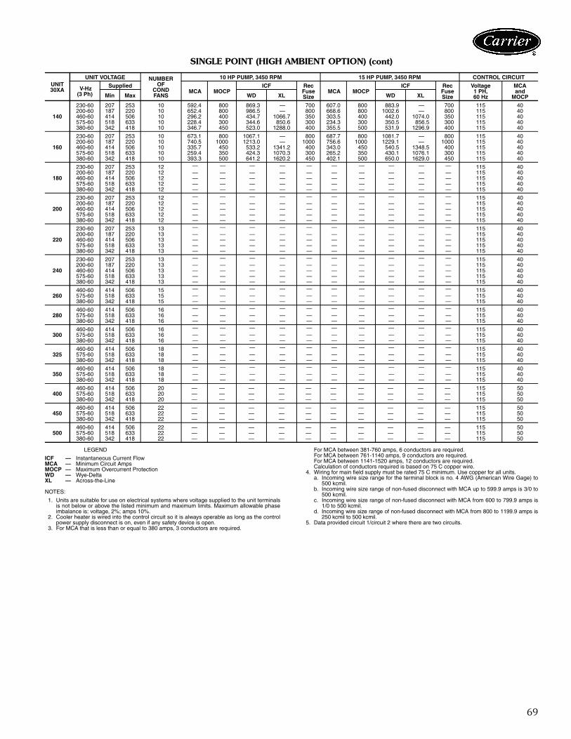
69
SINGLE POINT (HIGH AMBIENT OPTION) (cont)
LEGEND
NOTES:
1. Units are suitable for use on electrical systems where voltage supplied to the unit terminalsis not below or above the listed minimum and maximum limits. Maximum allowable phaseimbalance is: voltage, 2%; amps 10%.
2. Cooler heater is wired into the control circuit so it is always operable as long as the controlpower supply disconnect is on, even if any safety device is open.
3. For MCA that is less than or equal to 380 amps, 3 conductors are required.
For MCA between 381-760 amps, 6 conductors are required.For MCA between 761-1140 amps, 9 conductors are required.For MCA between 1141-1520 amps, 12 conductors are required.Calculation of conductors required is based on 75 C copper wire.
4. Wiring for main field supply must be rated 75 C minimum. Use copper for all units.a. Incoming wire size range for the terminal block is no. 4 AWG (American Wire Gage) to
500 kcmil.b. Incoming wire size range of non-fused disconnect with MCA up to 599.9 amps is 3/0 to
500 kcmil.c. Incoming wire size range of non-fused disconnect with MCA from 600 to 799.9 amps is
1/0 to 500 kcmil.d. Incoming wire size range of non-fused disconnect with MCA from 800 to 1199.9 amps is
250 kcmil to 500 kcmil.5. Data provided circuit 1/circuit 2 where there are two circuits.
UNIT30XA
UNIT VOLTAGE NUMBEROF
CONDFANS
10 HP PUMP, 3450 RPM 15 HP PUMP, 3450 RPM CONTROL CIRCUIT
V-Hz(3 Ph)
Supplied MCA MOCP
ICF RecFuseSize
MCA MOCPICF Rec
FuseSize
Voltage1 PH, 60 Hz
MCA and
MOCPMin Max WD XL WD XL
140
230-60 207 253 10 592.4 800 869.3 — 700 607.0 800 883.9 — 700 115 40200-60 187 220 10 652.4 800 986.5 — 800 668.6 800 1002.6 — 800 115 40460-60 414 506 10 296.2 400 434.7 1066.7 350 303.5 400 442.0 1074.0 350 115 40575-60 518 633 10 228.4 300 344.6 850.6 300 234.3 300 350.5 856.5 300 115 40380-60 342 418 10 346.7 450 523.0 1288.0 400 355.5 500 531.9 1296.9 400 115 40
160
230-60 207 253 10 673.1 800 1067.1 — 800 687.7 800 1081.7 — 800 115 40200-60 187 220 10 740.5 1000 1213.0 — 1000 756.6 1000 1229.1 — 1000 115 40460-60 414 506 10 335.7 450 533.2 1341.2 400 343.0 450 540.5 1348.5 400 115 40575-60 518 633 10 259.4 350 424.3 1070.3 300 265.2 350 430.1 1076.1 300 115 40380-60 342 418 10 393.3 500 641.2 1620.2 450 402.1 500 650.0 1629.0 450 115 40
180
230-60 207 253 12 — — — — — — — — — — 115 40200-60 187 220 12 — — — — — — — — — — 115 40460-60 414 506 12 — — — — — — — — — — 115 40575-60 518 633 12 — — — — — — — — — — 115 40380-60 342 418 12 — — — — — — — — — — 115 40
200
230-60 207 253 12 — — — — — — — — — — 115 40200-60 187 220 12 — — — — — — — — — — 115 40460-60 414 506 12 — — — — — — — — — — 115 40575-60 518 633 12 — — — — — — — — — — 115 40380-60 342 418 12 — — — — — — — — — — 115 40
220
230-60 207 253 13 — — — — — — — — — — 115 40200-60 187 220 13 — — — — — — — — — — 115 40460-60 414 506 13 — — — — — — — — — — 115 40575-60 518 633 13 — — — — — — — — — — 115 40380-60 342 418 13 — — — — — — — — — — 115 40
240
230-60 207 253 13 — — — — — — — — — — 115 40200-60 187 220 13 — — — — — — — — — — 115 40460-60 414 506 13 — — — — — — — — — — 115 40575-60 518 633 13 — — — — — — — — — — 115 40380-60 342 418 13 — — — — — — — — — — 115 40
260460-60 414 506 15 — — — — — — — — — — 115 40575-60 518 633 15 — — — — — — — — — — 115 40380-60 342 418 15 — — — — — — — — — — 115 40
280460-60 414 506 16 — — — — — — — — — — 115 40575-60 518 633 16 — — — — — — — — — — 115 40380-60 342 418 16 — — — — — — — — — — 115 40
300460-60 414 506 16 — — — — — — — — — — 115 40575-60 518 633 16 — — — — — — — — — — 115 40380-60 342 418 16 — — — — — — — — — — 115 40
325460-60 414 506 18 — — — — — — — — — — 115 40575-60 518 633 18 — — — — — — — — — — 115 40380-60 342 418 18 — — — — — — — — — — 115 40
350460-60 414 506 18 — — — — — — — — — — 115 40575-60 518 633 18 — — — — — — — — — — 115 40380-60 342 418 18 — — — — — — — — — — 115 40
400460-60 414 506 20 — — — — — — — — — — 115 50575-60 518 633 20 — — — — — — — — — — 115 50380-60 342 418 20 — — — — — — — — — — 115 50
450460-60 414 506 22 — — — — — — — — — — 115 50575-60 518 633 22 — — — — — — — — — — 115 50380-60 342 418 22 — — — — — — — — — — 115 50
500460-60 414 506 22 — — — — — — — — — — 115 50575-60 518 633 22 — — — — — — — — — — 115 50380-60 342 418 22 — — — — — — — — — — 115 50
ICF — Instantaneous Current FlowMCA — Minimum Circuit AmpsMOCP — Maximum Overcurrent ProtectionWD — Wye-DeltaXL — Across-the-Line
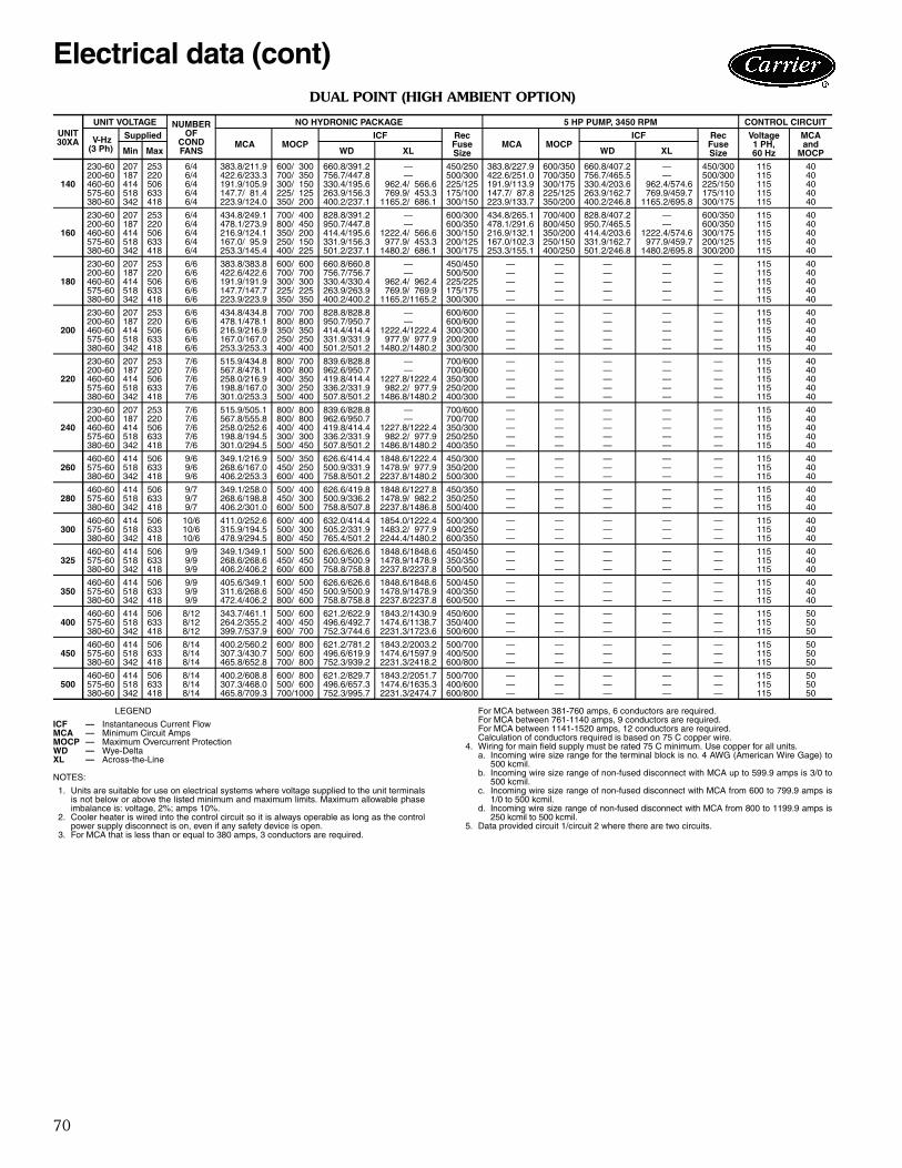
70
DUAL POINT (HIGH AMBIENT OPTION)
LEGEND
NOTES:
1. Units are suitable for use on electrical systems where voltage supplied to the unit terminalsis not below or above the listed minimum and maximum limits. Maximum allowable phaseimbalance is: voltage, 2%; amps 10%.
2. Cooler heater is wired into the control circuit so it is always operable as long as the controlpower supply disconnect is on, even if any safety device is open.
3. For MCA that is less than or equal to 380 amps, 3 conductors are required.
For MCA between 381-760 amps, 6 conductors are required.For MCA between 761-1140 amps, 9 conductors are required.For MCA between 1141-1520 amps, 12 conductors are required.Calculation of conductors required is based on 75 C copper wire.
4. Wiring for main field supply must be rated 75 C minimum. Use copper for all units.a. Incoming wire size range for the terminal block is no. 4 AWG (American Wire Gage) to
500 kcmil.b. Incoming wire size range of non-fused disconnect with MCA up to 599.9 amps is 3/0 to
500 kcmil.c. Incoming wire size range of non-fused disconnect with MCA from 600 to 799.9 amps is
1/0 to 500 kcmil.d. Incoming wire size range of non-fused disconnect with MCA from 800 to 1199.9 amps is
250 kcmil to 500 kcmil.5. Data provided circuit 1/circuit 2 where there are two circuits.
UNIT30XA
UNIT VOLTAGE NUMBEROF
CONDFANS
NO HYDRONIC PACKAGE 5 HP PUMP, 3450 RPM CONTROL CIRCUIT
V-Hz(3 Ph)
Supplied MCA MOCP
ICF RecFuseSize
MCA MOCPICF Rec
FuseSize
Voltage1 PH, 60 Hz
MCA and
MOCPMin Max WD XL WD XL
140
230-60 207 253 6/4 383.8/211.9 600/ 300 660.8/391.2 — 450/250 383.8/227.9 600/350 660.8/407.2 — 450/300 115 40200-60 187 220 6/4 422.6/233.3 700/ 350 756.7/447.8 — 500/300 422.6/251.0 700/350 756.7/465.5 — 500/300 115 40460-60 414 506 6/4 191.9/105.9 300/ 150 330.4/195.6 962.4/ 566.6 225/125 191.9/113.9 300/175 330.4/203.6 962.4/574.6 225/150 115 40575-60 518 633 6/4 147.7/ 81.4 225/ 125 263.9/156.3 769.9/ 453.3 175/100 147.7/ 87.8 225/125 263.9/162.7 769.9/459.7 175/110 115 40380-60 342 418 6/4 223.9/124.0 350/ 200 400.2/237.1 1165.2/ 686.1 300/150 223.9/133.7 350/200 400.2/246.8 1165.2/695.8 300/175 115 40
160
230-60 207 253 6/4 434.8/249.1 700/ 400 828.8/391.2 — 600/300 434.8/265.1 700/400 828.8/407.2 — 600/350 115 40200-60 187 220 6/4 478.1/273.9 800/ 450 950.7/447.8 — 600/350 478.1/291.6 800/450 950.7/465.5 — 600/350 115 40460-60 414 506 6/4 216.9/124.1 350/ 200 414.4/195.6 1222.4/ 566.6 300/150 216.9/132.1 350/200 414.4/203.6 1222.4/574.6 300/175 115 40575-60 518 633 6/4 167.0/ 95.9 250/ 150 331.9/156.3 977.9/ 453.3 200/125 167.0/102.3 250/150 331.9/162.7 977.9/459.7 200/125 115 40380-60 342 418 6/4 253.3/145.4 400/ 225 501.2/237.1 1480.2/ 686.1 300/175 253.3/155.1 400/250 501.2/246.8 1480.2/695.8 300/200 115 40
180
230-60 207 253 6/6 383.8/383.8 600/ 600 660.8/660.8 — 450/450 — — — — — 115 40200-60 187 220 6/6 422.6/422.6 700/ 700 756.7/756.7 — 500/500 — — — — — 115 40460-60 414 506 6/6 191.9/191.9 300/ 300 330.4/330.4 962.4/ 962.4 225/225 — — — — — 115 40575-60 518 633 6/6 147.7/147.7 225/ 225 263.9/263.9 769.9/ 769.9 175/175 — — — — — 115 40380-60 342 418 6/6 223.9/223.9 350/ 350 400.2/400.2 1165.2/1165.2 300/300 — — — — — 115 40
200
230-60 207 253 6/6 434.8/434.8 700/ 700 828.8/828.8 — 600/600 — — — — — 115 40200-60 187 220 6/6 478.1/478.1 800/ 800 950.7/950.7 — 600/600 — — — — — 115 40460-60 414 506 6/6 216.9/216.9 350/ 350 414.4/414.4 1222.4/1222.4 300/300 — — — — — 115 40575-60 518 633 6/6 167.0/167.0 250/ 250 331.9/331.9 977.9/ 977.9 200/200 — — — — — 115 40380-60 342 418 6/6 253.3/253.3 400/ 400 501.2/501.2 1480.2/1480.2 300/300 — — — — — 115 40
220
230-60 207 253 7/6 515.9/434.8 800/ 700 839.6/828.8 — 700/600 — — — — — 115 40200-60 187 220 7/6 567.8/478.1 800/ 800 962.6/950.7 — 700/600 — — — — — 115 40460-60 414 506 7/6 258.0/216.9 400/ 350 419.8/414.4 1227.8/1222.4 350/300 — — — — — 115 40575-60 518 633 7/6 198.8/167.0 300/ 250 336.2/331.9 982.2/ 977.9 250/200 — — — — — 115 40380-60 342 418 7/6 301.0/253.3 500/ 400 507.8/501.2 1486.8/1480.2 400/300 — — — — — 115 40
240
230-60 207 253 7/6 515.9/505.1 800/ 800 839.6/828.8 — 700/600 — — — — — 115 40200-60 187 220 7/6 567.8/555.8 800/ 800 962.6/950.7 — 700/700 — — — — — 115 40460-60 414 506 7/6 258.0/252.6 400/ 400 419.8/414.4 1227.8/1222.4 350/300 — — — — — 115 40575-60 518 633 7/6 198.8/194.5 300/ 300 336.2/331.9 982.2/ 977.9 250/250 — — — — — 115 40380-60 342 418 7/6 301.0/294.5 500/ 450 507.8/501.2 1486.8/1480.2 400/350 — — — — — 115 40
260460-60 414 506 9/6 349.1/216.9 500/ 350 626.6/414.4 1848.6/1222.4 450/300 — — — — — 115 40575-60 518 633 9/6 268.6/167.0 450/ 250 500.9/331.9 1478.9/ 977.9 350/200 — — — — — 115 40380-60 342 418 9/6 406.2/253.3 600/ 400 758.8/501.2 2237.8/1480.2 500/300 — — — — — 115 40
280460-60 414 506 9/7 349.1/258.0 500/ 400 626.6/419.8 1848.6/1227.8 450/350 — — — — — 115 40575-60 518 633 9/7 268.6/198.8 450/ 300 500.9/336.2 1478.9/ 982.2 350/250 — — — — — 115 40380-60 342 418 9/7 406.2/301.0 600/ 500 758.8/507.8 2237.8/1486.8 500/400 — — — — — 115 40
300460-60 414 506 10/6 411.0/252.6 600/ 400 632.0/414.4 1854.0/1222.4 500/300 — — — — — 115 40575-60 518 633 10/6 315.9/194.5 500/ 300 505.2/331.9 1483.2/ 977.9 400/250 — — — — — 115 40380-60 342 418 10/6 478.9/294.5 800/ 450 765.4/501.2 2244.4/1480.2 600/350 — — — — — 115 40
325460-60 414 506 9/9 349.1/349.1 500/ 500 626.6/626.6 1848.6/1848.6 450/450 — — — — — 115 40575-60 518 633 9/9 268.6/268.6 450/ 450 500.9/500.9 1478.9/1478.9 350/350 — — — — — 115 40380-60 342 418 9/9 406.2/406.2 600/ 600 758.8/758.8 2237.8/2237.8 500/500 — — — — — 115 40
350460-60 414 506 9/9 405.6/349.1 600/ 500 626.6/626.6 1848.6/1848.6 500/450 — — — — — 115 40575-60 518 633 9/9 311.6/268.6 500/ 450 500.9/500.9 1478.9/1478.9 400/350 — — — — — 115 40380-60 342 418 9/9 472.4/406.2 800/ 600 758.8/758.8 2237.8/2237.8 600/500 — — — — — 115 40
400460-60 414 506 8/12 343.7/461.1 500/ 600 621.2/622.9 1843.2/1430.9 450/600 — — — — — 115 50575-60 518 633 8/12 264.2/355.2 400/ 450 496.6/492.7 1474.6/1138.7 350/400 — — — — — 115 50380-60 342 418 8/12 399.7/537.9 600/ 700 752.3/744.6 2231.3/1723.6 500/600 — — — — — 115 50
450460-60 414 506 8/14 400.2/560.2 600/ 800 621.2/781.2 1843.2/2003.2 500/700 — — — — — 115 50575-60 518 633 8/14 307.3/430.7 500/ 600 496.6/619.9 1474.6/1597.9 400/500 — — — — — 115 50380-60 342 418 8/14 465.8/652.8 700/ 800 752.3/939.2 2231.3/2418.2 600/800 — — — — — 115 50
500460-60 414 506 8/14 400.2/608.8 600/ 800 621.2/829.7 1843.2/2051.7 500/700 — — — — — 115 50575-60 518 633 8/14 307.3/468.0 500/ 600 496.6/657.3 1474.6/1635.3 400/600 — — — — — 115 50380-60 342 418 8/14 465.8/709.3 700/1000 752.3/995.7 2231.3/2474.7 600/800 — — — — — 115 50
ICF — Instantaneous Current FlowMCA — Minimum Circuit AmpsMOCP — Maximum Overcurrent ProtectionWD — Wye-DeltaXL — Across-the-Line
Electrical data (cont)
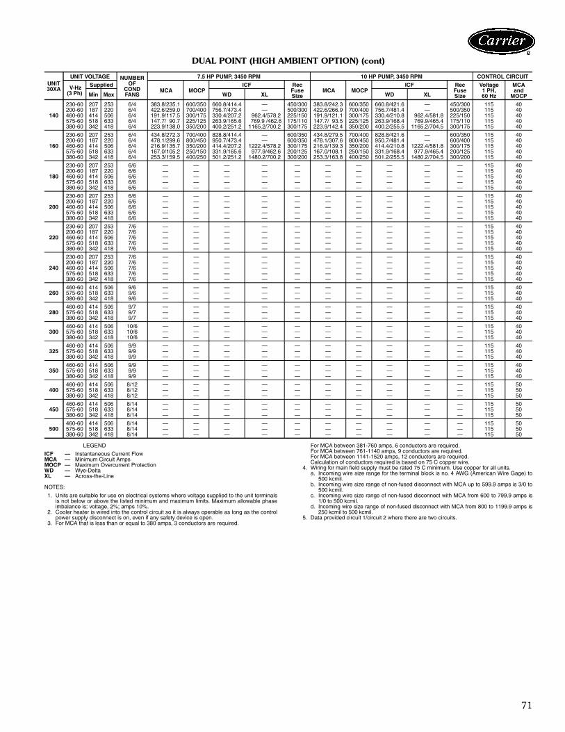
71
DUAL POINT (HIGH AMBIENT OPTION) (cont)
LEGEND
NOTES:
1. Units are suitable for use on electrical systems where voltage supplied to the unit terminalsis not below or above the listed minimum and maximum limits. Maximum allowable phaseimbalance is: voltage, 2%; amps 10%.
2. Cooler heater is wired into the control circuit so it is always operable as long as the controlpower supply disconnect is on, even if any safety device is open.
3. For MCA that is less than or equal to 380 amps, 3 conductors are required.
For MCA between 381-760 amps, 6 conductors are required.For MCA between 761-1140 amps, 9 conductors are required.For MCA between 1141-1520 amps, 12 conductors are required.Calculation of conductors required is based on 75 C copper wire.
4. Wiring for main field supply must be rated 75 C minimum. Use copper for all units.a. Incoming wire size range for the terminal block is no. 4 AWG (American Wire Gage) to
500 kcmil.b. Incoming wire size range of non-fused disconnect with MCA up to 599.9 amps is 3/0 to
500 kcmil.c. Incoming wire size range of non-fused disconnect with MCA from 600 to 799.9 amps is
1/0 to 500 kcmil.d. Incoming wire size range of non-fused disconnect with MCA from 800 to 1199.9 amps is
250 kcmil to 500 kcmil.5. Data provided circuit 1/circuit 2 where there are two circuits.
UNIT30XA
UNIT VOLTAGE NUMBEROF
CONDFANS
7.5 HP PUMP, 3450 RPM 10 HP PUMP, 3450 RPM CONTROL CIRCUIT
V-Hz(3 Ph)
Supplied MCA MOCP
ICF RecFuseSize
MCA MOCPICF Rec
FuseSize
Voltage1 PH, 60 Hz
MCA and
MOCPMin Max WD XL WD XL
140
230-60 207 253 6/4 383.8/235.1 600/350 660.8/414.4 — 450/300 383.8/242.3 600/350 660.8/421.6 — 450/300 115 40200-60 187 220 6/4 422.6/259.0 700/400 756.7/473.4 — 500/300 422.6/266.9 700/400 756.7/481.4 — 500/350 115 40460-60 414 506 6/4 191.9/117.5 300/175 330.4/207.2 962.4/578.2 225/150 191.9/121.1 300/175 330.4/210.8 962.4/581.8 225/150 115 40575-60 518 633 6/4 147.7/ 90.7 225/125 263.9/165.6 769.9 /462.6 175/110 147.7/ 93.5 225/125 263.9/168.4 769.9/465.4 175/110 115 40380-60 342 418 6/4 223.9/138.0 350/200 400.2/251.2 1165.2/700.2 300/175 223.9/142.4 350/200 400.2/255.5 1165.2/704.5 300/175 115 40
160
230-60 207 253 6/4 434.8/272.3 700/400 828.8/414.4 — 600/350 434.8/279.5 700/400 828.8/421.6 — 600/350 115 40200-60 187 220 6/4 478.1/299.6 800/450 950.7/473.4 — 600/350 478.1/307.6 800/450 950.7/481.4 — 600/400 115 40460-60 414 506 6/4 216.9/135.7 350/200 414.4/207.2 1222.4/578.2 300/175 216.9/139.3 350/200 414.4/210.8 1222.4/581.8 300/175 115 40575-60 518 633 6/4 167.0/105.2 250/150 331.9/165.6 977.9/462.6 200/125 167.0/108.1 250/150 331.9/168.4 977.9/465.4 200/125 115 40380-60 342 418 6/4 253.3/159.5 400/250 501.2/251.2 1480.2/700.2 300/200 253.3/163.8 400/250 501.2/255.5 1480.2/704.5 300/200 115 40
180
230-60 207 253 6/6 — — — — — — — — — — 115 40200-60 187 220 6/6 — — — — — — — — — — 115 40460-60 414 506 6/6 — — — — — — — — — — 115 40575-60 518 633 6/6 — — — — — — — — — — 115 40380-60 342 418 6/6 — — — — — — — — — — 115 40
200
230-60 207 253 6/6 — — — — — — — — — — 115 40200-60 187 220 6/6 — — — — — — — — — — 115 40460-60 414 506 6/6 — — — — — — — — — — 115 40575-60 518 633 6/6 — — — — — — — — — — 115 40380-60 342 418 6/6 — — — — — — — — — — 115 40
220
230-60 207 253 7/6 — — — — — — — — — — 115 40200-60 187 220 7/6 — — — — — — — — — — 115 40460-60 414 506 7/6 — — — — — — — — — — 115 40575-60 518 633 7/6 — — — — — — — — — — 115 40380-60 342 418 7/6 — — — — — — — — — — 115 40
240
230-60 207 253 7/6 — — — — — — — — — — 115 40200-60 187 220 7/6 — — — — — — — — — — 115 40460-60 414 506 7/6 — — — — — — — — — — 115 40575-60 518 633 7/6 — — — — — — — — — — 115 40380-60 342 418 7/6 — — — — — — — — — — 115 40
260460-60 414 506 9/6 — — — — — — — — — — 115 40575-60 518 633 9/6 — — — — — — — — — — 115 40380-60 342 418 9/6 — — — — — — — — — — 115 40
280460-60 414 506 9/7 — — — — — — — — — — 115 40575-60 518 633 9/7 — — — — — — — — — — 115 40380-60 342 418 9/7 — — — — — — — — — — 115 40
300460-60 414 506 10/6 — — — — — — — — — — 115 40575-60 518 633 10/6 — — — — — — — — — — 115 40380-60 342 418 10/6 — — — — — — — — — — 115 40
325460-60 414 506 9/9 — — — — — — — — — — 115 40575-60 518 633 9/9 — — — — — — — — — — 115 40380-60 342 418 9/9 — — — — — — — — — — 115 40
350460-60 414 506 9/9 — — — — — — — — — — 115 40575-60 518 633 9/9 — — — — — — — — — — 115 40380-60 342 418 9/9 — — — — — — — — — — 115 40
400460-60 414 506 8/12 — — — — — — — — — — 115 50575-60 518 633 8/12 — — — — — — — — — — 115 50380-60 342 418 8/12 — — — — — — — — — — 115 50
450460-60 414 506 8/14 — — — — — — — — — — 115 50575-60 518 633 8/14 — — — — — — — — — — 115 50380-60 342 418 8/14 — — — — — — — — — — 115 50
500460-60 414 506 8/14 — — — — — — — — — — 115 50575-60 518 633 8/14 — — — — — — — — — — 115 50380-60 342 418 8/14 — — — — — — — — — — 115 50
ICF — Instantaneous Current FlowMCA — Minimum Circuit AmpsMOCP — Maximum Overcurrent ProtectionWD — Wye-DeltaXL — Across-the-Line
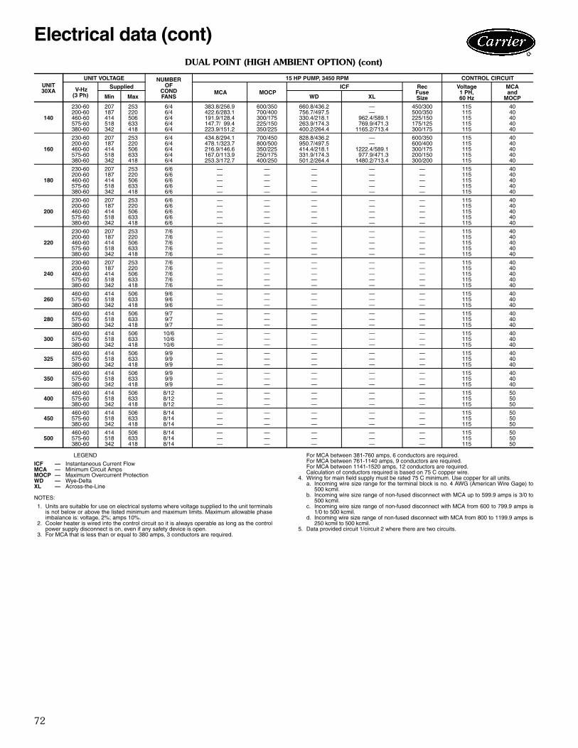
72
DUAL POINT (HIGH AMBIENT OPTION) (cont)
LEGEND
NOTES:
1. Units are suitable for use on electrical systems where voltage supplied to the unit terminalsis not below or above the listed minimum and maximum limits. Maximum allowable phaseimbalance is: voltage, 2%; amps 10%.
2. Cooler heater is wired into the control circuit so it is always operable as long as the controlpower supply disconnect is on, even if any safety device is open.
3. For MCA that is less than or equal to 380 amps, 3 conductors are required.
For MCA between 381-760 amps, 6 conductors are required.For MCA between 761-1140 amps, 9 conductors are required.For MCA between 1141-1520 amps, 12 conductors are required.Calculation of conductors required is based on 75 C copper wire.
4. Wiring for main field supply must be rated 75 C minimum. Use copper for all units.a. Incoming wire size range for the terminal block is no. 4 AWG (American Wire Gage) to
500 kcmil.b. Incoming wire size range of non-fused disconnect with MCA up to 599.9 amps is 3/0 to
500 kcmil.c. Incoming wire size range of non-fused disconnect with MCA from 600 to 799.9 amps is
1/0 to 500 kcmil.d. Incoming wire size range of non-fused disconnect with MCA from 800 to 1199.9 amps is
250 kcmil to 500 kcmil.5. Data provided circuit 1/circuit 2 where there are two circuits.
UNIT30XA
UNIT VOLTAGE NUMBEROF
CONDFANS
15 HP PUMP, 3450 RPM CONTROL CIRCUIT
V-Hz(3 Ph)
Supplied MCA MOCP
ICF RecFuseSize
Voltage1 PH, 60 Hz
MCA and
MOCPMin Max WD XL
140
230-60 207 253 6/4 383.8/256.9 600/350 660.8/436.2 — 450/300 115 40200-60 187 220 6/4 422.6/283.1 700/400 756.7/497.5 — 500/350 115 40460-60 414 506 6/4 191.9/128.4 300/175 330.4/218.1 962.4/589.1 225/150 115 40575-60 518 633 6/4 147.7/ 99.4 225/150 263.9/174.3 769.9/471.3 175/125 115 40380-60 342 418 6/4 223.9/151.2 350/225 400.2/264.4 1165.2/713.4 300/175 115 40
160
230-60 207 253 6/4 434.8/294.1 700/450 828.8/436.2 — 600/350 115 40200-60 187 220 6/4 478.1/323.7 800/500 950.7/497.5 — 600/400 115 40460-60 414 506 6/4 216.9/146.6 350/225 414.4/218.1 1222.4/589.1 300/175 115 40575-60 518 633 6/4 167.0/113.9 250/175 331.9/174.3 977.9/471.3 200/150 115 40380-60 342 418 6/4 253.3/172.7 400/250 501.2/264.4 1480.2/713.4 300/200 115 40
180
230-60 207 253 6/6 — — — — — 115 40200-60 187 220 6/6 — — — — — 115 40460-60 414 506 6/6 — — — — — 115 40575-60 518 633 6/6 — — — — — 115 40380-60 342 418 6/6 — — — — — 115 40
200
230-60 207 253 6/6 — — — — — 115 40200-60 187 220 6/6 — — — — — 115 40460-60 414 506 6/6 — — — — — 115 40575-60 518 633 6/6 — — — — — 115 40380-60 342 418 6/6 — — — — — 115 40
220
230-60 207 253 7/6 — — — — — 115 40200-60 187 220 7/6 — — — — — 115 40460-60 414 506 7/6 — — — — — 115 40575-60 518 633 7/6 — — — — — 115 40380-60 342 418 7/6 — — — — — 115 40
240
230-60 207 253 7/6 — — — — — 115 40200-60 187 220 7/6 — — — — — 115 40460-60 414 506 7/6 — — — — — 115 40575-60 518 633 7/6 — — — — — 115 40380-60 342 418 7/6 — — — — — 115 40
260460-60 414 506 9/6 — — — — — 115 40575-60 518 633 9/6 — — — — — 115 40380-60 342 418 9/6 — — — — — 115 40
280460-60 414 506 9/7 — — — — — 115 40575-60 518 633 9/7 — — — — — 115 40380-60 342 418 9/7 — — — — — 115 40
300460-60 414 506 10/6 — — — — — 115 40575-60 518 633 10/6 — — — — — 115 40380-60 342 418 10/6 — — — — — 115 40
325460-60 414 506 9/9 — — — — — 115 40575-60 518 633 9/9 — — — — — 115 40380-60 342 418 9/9 — — — — — 115 40
350460-60 414 506 9/9 — — — — — 115 40575-60 518 633 9/9 — — — — — 115 40380-60 342 418 9/9 — — — — — 115 40
400460-60 414 506 8/12 — — — — — 115 50575-60 518 633 8/12 — — — — — 115 50380-60 342 418 8/12 — — — — — 115 50
450460-60 414 506 8/14 — — — — — 115 50575-60 518 633 8/14 — — — — — 115 50380-60 342 418 8/14 — — — — — 115 50
500460-60 414 506 8/14 — — — — — 115 50575-60 518 633 8/14 — — — — — 115 50380-60 342 418 8/14 — — — — — 115 50
ICF — Instantaneous Current FlowMCA — Minimum Circuit AmpsMOCP — Maximum Overcurrent ProtectionWD — Wye-DeltaXL — Across-the-Line
Electrical data (cont)
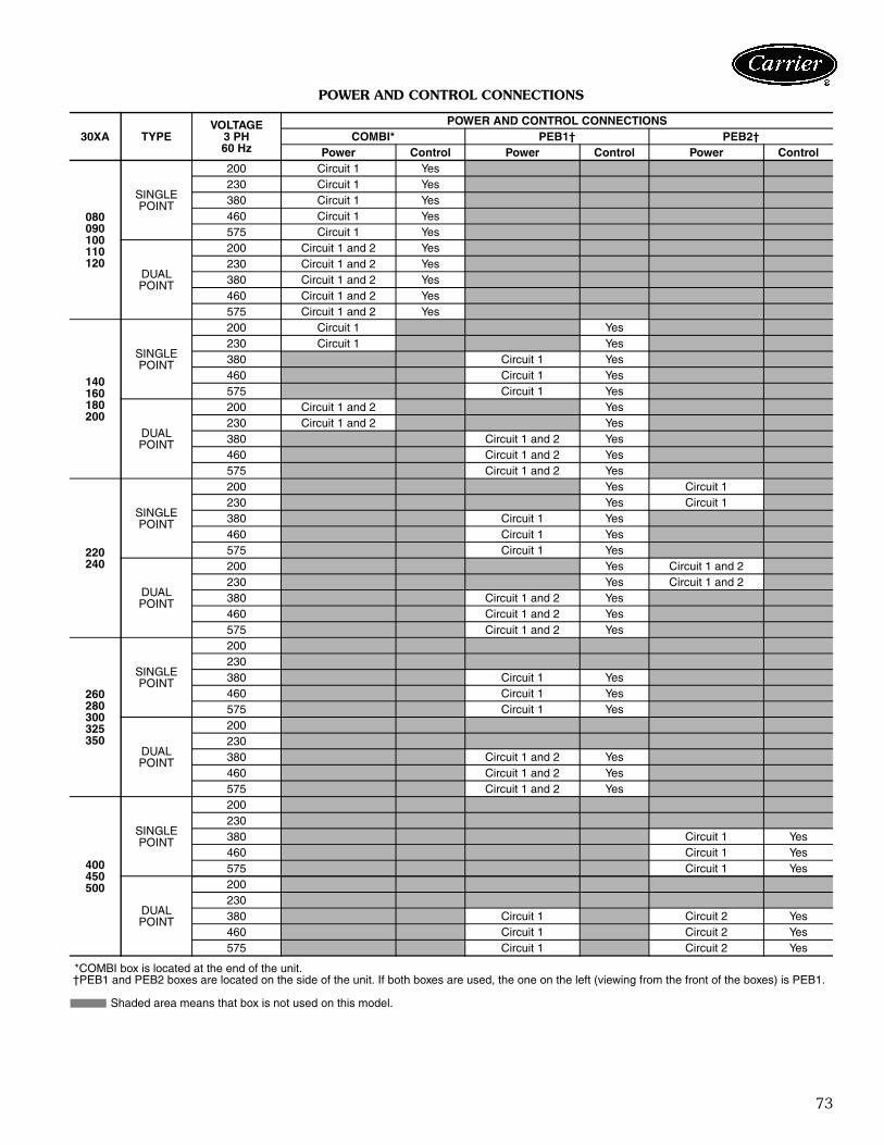
73
POWER AND CONTROL CONNECTIONS
*COMBI box is located at the end of the unit.†PEB1 and PEB2 boxes are located on the side of the unit. If both boxes are used, the one on the left (viewing from the front of the boxes) is PEB1.
Shaded area means that box is not used on this model.
30XA TYPEVOLTAGE
3 PH 60 Hz
POWER AND CONTROL CONNECTIONSCOMBI* PEB1† PEB2†
Power Control Power Control Power Control
080 090 100 110 120
SINGLEPOINT
200 Circuit 1 Yes230 Circuit 1 Yes380 Circuit 1 Yes460 Circuit 1 Yes575 Circuit 1 Yes
DUALPOINT
200 Circuit 1 and 2 Yes230 Circuit 1 and 2 Yes380 Circuit 1 and 2 Yes460 Circuit 1 and 2 Yes575 Circuit 1 and 2 Yes
140160180200
SINGLEPOINT
200 Circuit 1 Yes230 Circuit 1 Yes380 Circuit 1 Yes460 Circuit 1 Yes575 Circuit 1 Yes
DUALPOINT
200 Circuit 1 and 2 Yes230 Circuit 1 and 2 Yes380 Circuit 1 and 2 Yes460 Circuit 1 and 2 Yes575 Circuit 1 and 2 Yes
220 240
SINGLEPOINT
200 Yes Circuit 1230 Yes Circuit 1380 Circuit 1 Yes460 Circuit 1 Yes575 Circuit 1 Yes
DUALPOINT
200 Yes Circuit 1 and 2230 Yes Circuit 1 and 2380 Circuit 1 and 2 Yes460 Circuit 1 and 2 Yes575 Circuit 1 and 2 Yes
260 280300325350
SINGLEPOINT
200230380 Circuit 1 Yes460 Circuit 1 Yes575 Circuit 1 Yes
DUALPOINT
200230380 Circuit 1 and 2 Yes460 Circuit 1 and 2 Yes575 Circuit 1 and 2 Yes
400 450 500
SINGLEPOINT
200230380 Circuit 1 Yes460 Circuit 1 Yes575 Circuit 1 Yes
DUALPOINT
200230380 Circuit 1 Circuit 2 Yes460 Circuit 1 Circuit 2 Yes575 Circuit 1 Circuit 2 Yes
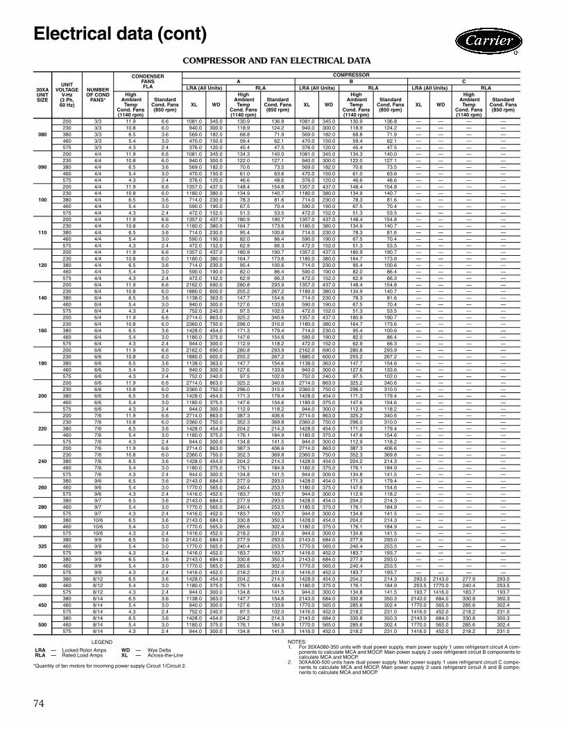
74
COMPRESSOR AND FAN ELECTRICAL DATA
LEGEND
*Quantity of fan motors for incoming power supply Circuit 1/Circuit 2.
NOTES:1. For 30XA080-350 units with dual power supply, main power supply 1 uses refrigerant circuit A com-
ponents to calculate MCA and MOCP. Main power supply 2 uses refrigerant circuit B components tocalculate MCA and MOCP.
2. 30XA400-500 units have dual power supply. Main power supply 1 uses refrigerant circuit C compo-nents to calculate MCA and MOCP. Main power supply 2 uses refrigerant circuit A and B compo-nents to calculate MCA and MOCP.
30XA UNIT SIZE
UNIT VOLTAGE
V-Hz (3 Ph, 60 Hz)
NUMBER OF COND
FANS*
CONDENSER FANSFLA
COMPRESSORA B C
LRA (All Units) RLA LRA (All Units) RLA LRA (All Units) RLA
XL WD
High Ambient
Temp Cond. Fans (1140 rpm)
Standard Cond. Fans (850 rpm)
XL WD
High Ambient
Temp Cond. Fans (1140 rpm)
Standard Cond. Fans (850 rpm)
XL WD
High Ambient
Temp Cond. Fans (1140 rpm)
Standard Cond. Fans (850 rpm)
High Ambient
Temp Cond. Fans (1140 rpm)
Standard Cond. Fans (850 rpm)
080
200 3/3 11.9 6.6 1081.0 345.0 130.9 136.8 1081.0 345.0 130.9 136.8 — — — —230 3/3 10.8 6.0 940.0 300.0 118.9 124.2 940.0 300.0 118.9 124.2 — — — —380 3/3 6.5 3.6 569.0 182.0 68.8 71.9 569.0 182.0 68.8 71.9 — — — —460 3/3 5.4 3.0 470.0 150.0 59.4 62.1 470.0 150.0 59.4 62.1 — — — —575 3/3 4.3 2.4 376.0 120.0 45.4 47.5 376.0 120.0 45.4 47.5 — — — —
090
200 4/4 11.9 6.6 1081.0 345.0 134.3 140.0 1081.0 345.0 134.3 140.0 — — — —230 4/4 10.8 6.0 940.0 300.0 122.0 127.1 940.0 300.0 122.0 127.1 — — — —380 4/4 6.5 3.6 569.0 182.0 70.6 73.5 569.0 182.0 70.6 73.5 — — — —460 4/4 5.4 3.0 470.0 150.0 61.0 63.6 470.0 150.0 61.0 63.6 — — — —575 4/4 4.3 2.4 376.0 120.0 46.6 48.6 376.0 120.0 46.6 48.6 — — — —
100
200 4/4 11.9 6.6 1357.0 437.0 148.4 154.8 1357.0 437.0 148.4 154.8 — — — —230 4/4 10.8 6.0 1180.0 380.0 134.9 140.7 1180.0 380.0 134.9 140.7 — — — —380 4/4 6.5 3.6 714.0 230.0 78.3 81.6 714.0 230.0 78.3 81.6 — — — —460 4/4 5.4 3.0 590.0 190.0 67.5 70.4 590.0 190.0 67.5 70.4 — — — —575 4/4 4.3 2.4 472.0 152.0 51.3 53.5 472.0 152.0 51.3 53.5 — — — —
110
200 4/4 11.9 6.6 1357.0 437.0 180.9 190.7 1357.0 437.0 148.4 154.8 — — — —230 4/4 10.8 6.0 1180.0 380.0 164.7 173.6 1180.0 380.0 134.9 140.7 — — — —380 4/4 6.5 3.6 714.0 230.0 95.4 100.6 714.0 230.0 78.3 81.6 — — — —460 4/4 5.4 3.0 590.0 190.0 82.0 86.4 590.0 190.0 67.5 70.4 — — — —575 4/4 4.3 2.4 472.0 152.0 62.9 66.3 472.0 152.0 51.3 53.5 — — — —
120
200 4/4 11.9 6.6 1357.0 437.0 180.9 190.7 1357.0 437.0 180.9 190.7 — — — —230 4/4 10.8 6.0 1180.0 380.0 164.7 173.6 1180.0 380.0 164.7 173.6 — — — —380 4/4 6.5 3.6 714.0 230.0 95.4 100.6 714.0 230.0 95.4 100.6 — — — —460 4/4 5.4 3.0 590.0 190.0 82.0 86.4 590.0 190.0 82.0 86.4 — — — —575 4/4 4.3 2.4 472.0 152.0 62.9 66.3 472.0 152.0 62.9 66.3 — — — —
140
200 6/4 11.9 6.6 2162.0 690.0 280.8 293.9 1357.0 437.0 148.4 154.8 — — — —230 6/4 10.8 6.0 1880.0 600.0 255.2 267.2 1180.0 380.0 134.9 140.7 — — — —380 6/4 6.5 3.6 1138.0 363.0 147.7 154.6 714.0 230.0 78.3 81.6 — — — —460 6/4 5.4 3.0 940.0 300.0 127.6 133.6 590.0 190.0 67.5 70.4 — — — —575 6/4 4.3 2.4 752.0 240.0 97.5 102.0 472.0 152.0 51.3 53.5 — — — —
160
200 6/4 11.9 6.6 2714.0 863.0 325.2 340.6 1357.0 437.0 180.9 190.7 — — — —230 6/4 10.8 6.0 2360.0 750.0 296.0 310.0 1180.0 380.0 164.7 173.6 — — — —380 6/4 6.5 3.6 1428.0 454.0 171.3 179.4 714.0 230.0 95.4 100.6 — — — —460 6/4 5.4 3.0 1180.0 375.0 147.6 154.6 590.0 190.0 82.0 86.4 — — — —575 6/4 4.3 2.4 944.0 300.0 112.9 118.2 472.0 152.0 62.9 66.3 — — — —
180
200 6/6 11.9 6.6 2162.0 690.0 280.8 293.9 2162.0 690.0 280.8 293.9 — — — —230 6/6 10.8 6.0 1880.0 600.0 255.2 267.2 1880.0 600.0 255.2 267.2 — — — —380 6/6 6.5 3.6 1138.0 363.0 147.7 154.6 1138.0 363.0 147.7 154.6 — — — —460 6/6 5.4 3.0 940.0 300.0 127.6 133.6 940.0 300.0 127.6 133.6 — — — —575 6/6 4.3 2.4 752.0 240.0 97.5 102.0 752.0 240.0 97.5 102.0 — — — —
200
200 6/6 11.9 6.6 2714.0 863.0 325.2 340.6 2714.0 863.0 325.2 340.6 — — — —230 6/6 10.8 6.0 2360.0 750.0 296.0 310.0 2360.0 750.0 296.0 310.0 — — — —380 6/6 6.5 3.6 1428.0 454.0 171.3 179.4 1428.0 454.0 171.3 179.4 — — — —460 6/6 5.4 3.0 1180.0 375.0 147.6 154.6 1180.0 375.0 147.6 154.6 — — — —575 6/6 4.3 2.4 944.0 300.0 112.9 118.2 944.0 300.0 112.9 118.2 — — — —
220
200 7/6 11.9 6.6 2714.0 863.0 387.3 406.6 2714.0 863.0 325.2 340.6 — — — —230 7/6 10.8 6.0 2360.0 750.0 352.3 369.8 2360.0 750.0 296.0 310.0 — — — —380 7/6 6.5 3.6 1428.0 454.0 204.2 214.3 1428.0 454.0 171.3 179.4 — — — —460 7/6 5.4 3.0 1180.0 375.0 176.1 184.9 1180.0 375.0 147.6 154.6 — — — —575 7/6 4.3 2.4 944.0 300.0 134.8 141.5 944.0 300.0 112.9 118.2 — — — —
240
200 7/6 11.9 6.6 2714.0 863.0 387.3 406.6 2714.0 863.0 387.3 406.6 — — — —230 7/6 10.8 6.0 2360.0 750.0 352.3 369.8 2360.0 750.0 352.3 369.8 — — — —380 7/6 6.5 3.6 1428.0 454.0 204.2 214.3 1428.0 454.0 204.2 214.3 — — — —460 7/6 5.4 3.0 1180.0 375.0 176.1 184.9 1180.0 375.0 176.1 184.9 — — — —575 7/6 4.3 2.4 944.0 300.0 134.8 141.5 944.0 300.0 134.8 141.5 — — — —
260380 9/6 6.5 3.6 2143.0 684.0 277.9 293.0 1428.0 454.0 171.3 179.4 — — — —460 9/6 5.4 3.0 1770.0 565.0 240.4 253.5 1180.0 375.0 147.6 154.6 — — — —575 9/6 4.3 2.4 1416.0 452.0 183.7 193.7 944.0 300.0 112.9 118.2 — — — —
280380 9/7 6.5 3.6 2143.0 684.0 277.9 293.0 1428.0 454.0 204.2 214.3 — — — —460 9/7 5.4 3.0 1770.0 565.0 240.4 253.5 1180.0 375.0 176.1 184.9 — — — —575 9/7 4.3 2.4 1416.0 452.0 183.7 193.7 944.0 300.0 134.8 141.5 — — — —
300380 10/6 6.5 3.6 2143.0 684.0 330.8 350.3 1428.0 454.0 204.2 214.3 — — — —460 10/6 5.4 3.0 1770.0 565.0 285.6 302.4 1180.0 375.0 176.1 184.9 — — — —575 10/6 4.3 2.4 1416.0 452.0 218.2 231.0 944.0 300.0 134.8 141.5 — — — —
325380 9/9 6.5 3.6 2143.0 684.0 277.9 293.0 2143.0 684.0 277.9 293.0 — — — —460 9/9 5.4 3.0 1770.0 565.0 240.4 253.5 1770.0 565.0 240.4 253.5 — — — —575 9/9 4.3 2.4 1416.0 452.0 183.7 193.7 1416.0 452.0 183.7 193.7 — — — —
350380 9/9 6.5 3.6 2143.0 684.0 330.8 350.3 2143.0 684.0 277.9 293.0 — — — —460 9/9 5.4 3.0 1770.0 565.0 285.6 302.4 1770.0 565.0 240.4 253.5 — — — —575 9/9 4.3 2.4 1416.0 452.0 218.2 231.0 1416.0 452.0 183.7 193.7 — — — —
400380 8/12 6.5 3.6 1428.0 454.0 204.2 214.3 1428.0 454.0 204.2 214.3 293.0 2143.0 277.9 293.0460 8/12 5.4 3.0 1180.0 375.0 176.1 184.9 1180.0 375.0 176.1 184.9 253.5 1770.0 240.4 253.5575 8/12 4.3 2.4 944.0 300.0 134.8 141.5 944.0 300.0 134.8 141.5 193.7 1416.0 183.7 193.7
450380 8/14 6.5 3.6 1138.0 363.0 147.7 154.6 2143.0 684.0 330.8 350.3 2143.0 684.0 330.8 350.3460 8/14 5.4 3.0 940.0 300.0 127.6 133.6 1770.0 565.0 285.6 302.4 1770.0 565.0 285.6 302.4575 8/14 4.3 2.4 752.0 240.0 97.5 102.0 1416.0 452.0 218.2 231.0 1416.0 452.0 218.2 231.0
500380 8/14 6.5 3.6 1428.0 454.0 204.2 214.3 2143.0 684.0 330.8 350.3 2143.0 684.0 330.8 350.3460 8/14 5.4 3.0 1180.0 375.0 176.1 184.9 1770.0 565.0 285.6 302.4 1770.0 565.0 285.6 302.4575 8/14 4.3 2.4 944.0 300.0 134.8 141.5 1416.0 452.0 218.2 231.0 1416.0 452.0 218.2 231.0
LRA — Locked Rotor Amps WD — Wye DeltaRLA — Rated Load Amps XL — Across-the-Line
Electrical data (cont)
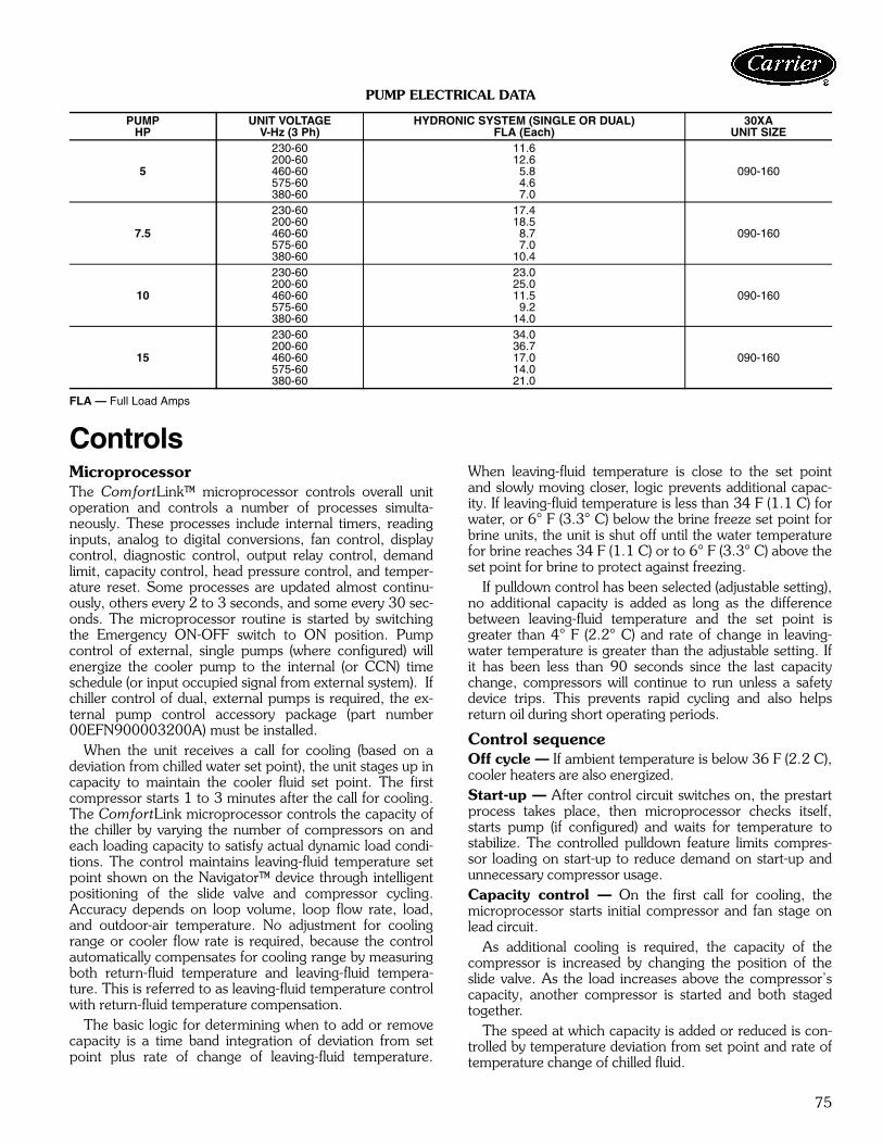
75
PUMP ELECTRICAL DATA
FLA — Full Load Amps
ControlsMicroprocessorThe ComfortLink™ microprocessor controls overall unitoperation and controls a number of processes simulta-neously. These processes include internal timers, readinginputs, analog to digital conversions, fan control, displaycontrol, diagnostic control, output relay control, demandlimit, capacity control, head pressure control, and temper-ature reset. Some processes are updated almost continu-ously, others every 2 to 3 seconds, and some every 30 sec-onds. The microprocessor routine is started by switchingthe Emergency ON-OFF switch to ON position. Pumpcontrol of external, single pumps (where configured) willenergize the cooler pump to the internal (or CCN) timeschedule (or input occupied signal from external system). Ifchiller control of dual, external pumps is required, the ex-ternal pump control accessory package (part number00EFN900003200A) must be installed.
When the unit receives a call for cooling (based on adeviation from chilled water set point), the unit stages up incapacity to maintain the cooler fluid set point. The firstcompressor starts 1 to 3 minutes after the call for cooling.The ComfortLink microprocessor controls the capacity ofthe chiller by varying the number of compressors on andeach loading capacity to satisfy actual dynamic load condi-tions. The control maintains leaving-fluid temperature setpoint shown on the Navigator™ device through intelligentpositioning of the slide valve and compressor cycling.Accuracy depends on loop volume, loop flow rate, load,and outdoor-air temperature. No adjustment for coolingrange or cooler flow rate is required, because the controlautomatically compensates for cooling range by measuringboth return-fluid temperature and leaving-fluid tempera-ture. This is referred to as leaving-fluid temperature controlwith return-fluid temperature compensation.
The basic logic for determining when to add or removecapacity is a time band integration of deviation from setpoint plus rate of change of leaving-fluid temperature.
When leaving-fluid temperature is close to the set pointand slowly moving closer, logic prevents additional capac-ity. If leaving-fluid temperature is less than 34 F (1.1 C) forwater, or 6° F (3.3° C) below the brine freeze set point forbrine units, the unit is shut off until the water temperaturefor brine reaches 34 F (1.1 C) or to 6° F (3.3° C) above theset point for brine to protect against freezing.
If pulldown control has been selected (adjustable setting),no additional capacity is added as long as the differencebetween leaving-fluid temperature and the set point isgreater than 4° F (2.2° C) and rate of change in leaving-water temperature is greater than the adjustable setting. Ifit has been less than 90 seconds since the last capacitychange, compressors will continue to run unless a safetydevice trips. This prevents rapid cycling and also helpsreturn oil during short operating periods.
Control sequenceOff cycle — If ambient temperature is below 36 F (2.2 C),cooler heaters are also energized.Start-up — After control circuit switches on, the prestartprocess takes place, then microprocessor checks itself,starts pump (if configured) and waits for temperature tostabilize. The controlled pulldown feature limits compres-sor loading on start-up to reduce demand on start-up andunnecessary compressor usage.Capacity control — On the first call for cooling, themicroprocessor starts initial compressor and fan stage onlead circuit.
As additional cooling is required, the capacity of thecompressor is increased by changing the position of theslide valve. As the load increases above the compressor’scapacity, another compressor is started and both stagedtogether.
The speed at which capacity is added or reduced is con-trolled by temperature deviation from set point and rate oftemperature change of chilled fluid.
PUMPHP
UNIT VOLTAGEV-Hz (3 Ph)
HYDRONIC SYSTEM (SINGLE OR DUAL)FLA (Each)
30XA UNIT SIZE
5
230-60 11.6
090-160200-60 12.6460-60 5.8575-60 4.6380-60 7.0
7.5
230-60 17.4
090-160200-60 18.5460-60 8.7575-60 7.0380-60 10.4
10
230-60 23.0
090-160200-60 25.0460-60 11.5575-60 9.2380-60 14.0
15
230-60 34.0
090-160200-60 36.7460-60 17.0575-60 14.0380-60 21.0
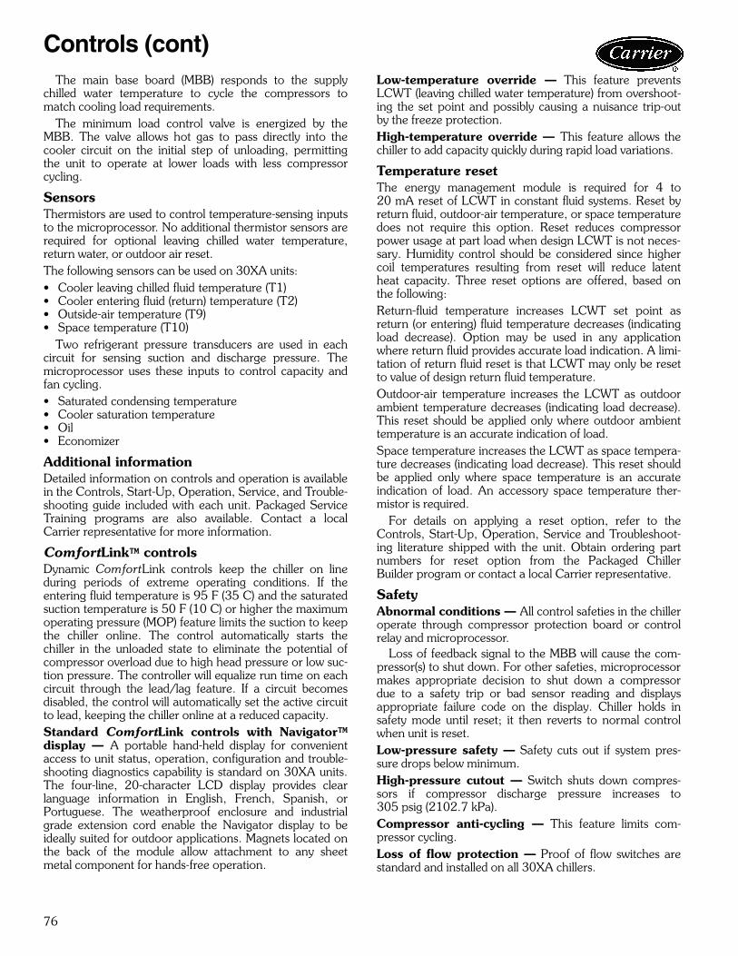
76
The main base board (MBB) responds to the supplychilled water temperature to cycle the compressors tomatch cooling load requirements.
The minimum load control valve is energized by theMBB. The valve allows hot gas to pass directly into thecooler circuit on the initial step of unloading, permittingthe unit to operate at lower loads with less compressorcycling.
SensorsThermistors are used to control temperature-sensing inputsto the microprocessor. No additional thermistor sensors arerequired for optional leaving chilled water temperature,return water, or outdoor air reset.The following sensors can be used on 30XA units:• Cooler leaving chilled fluid temperature (T1)• Cooler entering fluid (return) temperature (T2)• Outside-air temperature (T9)• Space temperature (T10)
Two refrigerant pressure transducers are used in eachcircuit for sensing suction and discharge pressure. Themicroprocessor uses these inputs to control capacity andfan cycling.• Saturated condensing temperature• Cooler saturation temperature• Oil• Economizer
Additional informationDetailed information on controls and operation is availablein the Controls, Start-Up, Operation, Service, and Trouble-shooting guide included with each unit. Packaged ServiceTraining programs are also available. Contact a localCarrier representative for more information.
ComfortLink™ controlsDynamic ComfortLink controls keep the chiller on lineduring periods of extreme operating conditions. If theentering fluid temperature is 95 F (35 C) and the saturatedsuction temperature is 50 F (10 C) or higher the maximumoperating pressure (MOP) feature limits the suction to keepthe chiller online. The control automatically starts thechiller in the unloaded state to eliminate the potential ofcompressor overload due to high head pressure or low suc-tion pressure. The controller will equalize run time on eachcircuit through the lead/lag feature. If a circuit becomesdisabled, the control will automatically set the active circuitto lead, keeping the chiller online at a reduced capacity.Standard ComfortLink controls with Navigator™display — A portable hand-held display for convenientaccess to unit status, operation, configuration and trouble-shooting diagnostics capability is standard on 30XA units.The four-line, 20-character LCD display provides clearlanguage information in English, French, Spanish, orPortuguese. The weatherproof enclosure and industrialgrade extension cord enable the Navigator display to beideally suited for outdoor applications. Magnets located onthe back of the module allow attachment to any sheetmetal component for hands-free operation.
Low-temperature override — This feature preventsLCWT (leaving chilled water temperature) from overshoot-ing the set point and possibly causing a nuisance trip-outby the freeze protection.High-temperature override — This feature allows thechiller to add capacity quickly during rapid load variations.
Temperature reset The energy management module is required for 4 to20 mA reset of LCWT in constant fluid systems. Reset byreturn fluid, outdoor-air temperature, or space temperaturedoes not require this option. Reset reduces compressorpower usage at part load when design LCWT is not neces-sary. Humidity control should be considered since highercoil temperatures resulting from reset will reduce latentheat capacity. Three reset options are offered, based onthe following:Return-fluid temperature increases LCWT set point asreturn (or entering) fluid temperature decreases (indicatingload decrease). Option may be used in any applicationwhere return fluid provides accurate load indication. A limi-tation of return fluid reset is that LCWT may only be resetto value of design return fluid temperature.Outdoor-air temperature increases the LCWT as outdoorambient temperature decreases (indicating load decrease).This reset should be applied only where outdoor ambienttemperature is an accurate indication of load.Space temperature increases the LCWT as space tempera-ture decreases (indicating load decrease). This reset shouldbe applied only where space temperature is an accurateindication of load. An accessory space temperature ther-mistor is required.
For details on applying a reset option, refer to theControls, Start-Up, Operation, Service and Troubleshoot-ing literature shipped with the unit. Obtain ordering partnumbers for reset option from the Packaged ChillerBuilder program or contact a local Carrier representative.
SafetyAbnormal conditions — All control safeties in the chilleroperate through compressor protection board or controlrelay and microprocessor.
Loss of feedback signal to the MBB will cause the com-pressor(s) to shut down. For other safeties, microprocessormakes appropriate decision to shut down a compressordue to a safety trip or bad sensor reading and displaysappropriate failure code on the display. Chiller holds insafety mode until reset; it then reverts to normal controlwhen unit is reset.Low-pressure safety — Safety cuts out if system pres-sure drops below minimum.High-pressure cutout — Switch shuts down compres-sors if compressor discharge pressure increases to305 psig (2102.7 kPa).Compressor anti-cycling — This feature limits com-pressor cycling.Loss of flow protection — Proof of flow switches arestandard and installed on all 30XA chillers.
Controls (cont)
77
Sensor failures — Failures are detected by themicroprocessor.
Accessory controlsDemand can be limited by controlling the chiller capacitythrough the demand limit control (the energy managementmodule is required for this function). This FIOP/accessoryinterfaces with the microprocessor to control the unit sothat the chiller’s kW demand does not exceed its setting. Itis activated from an external switch or a 4 to 20 mA signal.
The standard ComfortLink™ controller is programmedto accept various accessory temperature reset options(based on outdoor-air temperature [standard], return-fluidtemperature [standard], or space temperature [whichrequires accessory thermistor]), that resets the LCWT. Anaccessory thermistor (T10) is required if space temperaturereset is selected. The Energy Management Module (EMM)is only required for temperature reset that is initiated by a 4to 20 mA signal.
Demand limitIf the demand limit is applied, it limits the total power drawof unit to a selected point by controlling the number ofoperational compressors during periods of peak electricaldemand.
The energy management module is required for either2-step or 4 to 20 mA demand limit.
Electronic expansion valve (EXV)The EXV controls refrigerant flow to the cooler for differ-ent operating conditions by varying an orifice size toincrease or decrease the flow area through the valve basedon microprocessor input. The orifice is positioned by astepper motor through approximately 3,600 discrete stepsand is monitored every three seconds.
Diagnostics The microprocessor may be put through a service test (seeControls, Start-Up, Operation, Service, and Troubleshoot-ing literature). Service test confirms microprocessor isfunctional, informs observer through display the condition
of each sensor and switch in chiller, and allows observer tocheck for proper operation of fans and compressors.
Default settingsTo facilitate quick start-ups, 30XA chillers withComfortLink controls are pre-configured with a defaultsetting that assumes stand-alone operation supplying 44 F(6.6 C) chilled water.
Configuration settings will be based on any optionsor accessories included with the unit at the time ofmanufacturing.
Date and time are set to U.S.A. Eastern Time zone andwill need reconfiguring based on location and local timezone. If operation based on occupancy scheduling isdesired, schedule must be set during installation.
Ice dutyComfortLink controls have the capability of reduced leav-ing fluid temperature operation for thermal storage, or iceduty. The optional Energy Management display includesinput contacts for the “ice done” signal generated by thethermal storage control system. The ice duty feature maybe configured to start on an external input command or bythe ComfortLink standard internal scheduling function.The ice duty function requires brine modification for leav-ing fluid temperatures below 40 F (4.4 C). Ice duty may beused in combination with any other standard featuresoffered by the energy management module andComfortLink controls.
The production of ice, which is stored for peak coolingdemands, can significantly decrease energy costs. The unitproduces ice (normally at night) by supplying ice storagetanks with low temperature cooling fluid. The chiller takesadvantage of reduced ambient conditions at night for ice-making mode, so the capacity suffers a lower penalty forthe low leaving fluid temperatures.
At peak cooling demands, the chiller and the stored icemay share the cooling load to reduce operating costs. Thethermal storage system may potentially reduce the size ofthe chiller plant required to meet demand loads.
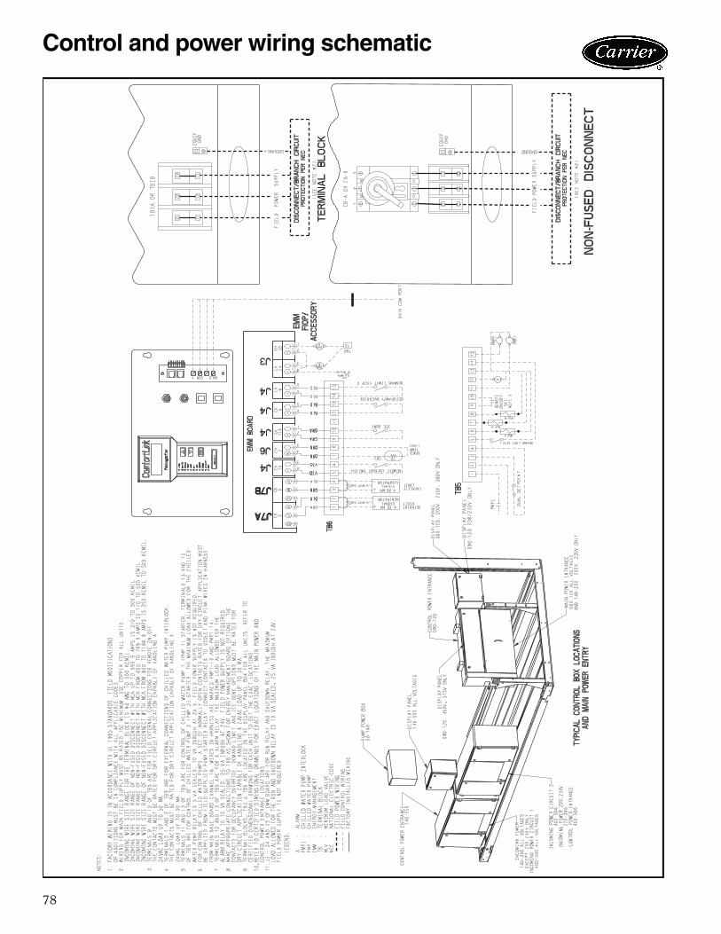
78
a30-4443
Control and power wiring schematic
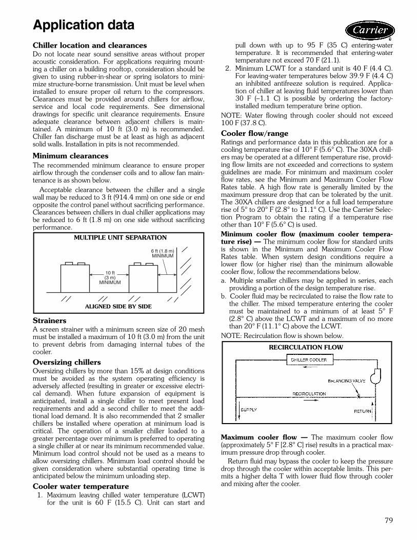
79
Chiller location and clearancesDo not locate near sound sensitive areas without properacoustic consideration. For applications requiring mount-ing a chiller on a building rooftop, consideration should begiven to using rubber-in-shear or spring isolators to mini-mize structure-borne transmission. Unit must be level wheninstalled to ensure proper oil return to the compressors.Clearances must be provided around chillers for airflow,service and local code requirements. See dimensionaldrawings for specific unit clearance requirements. Ensureadequate clearance between adjacent chillers is main-tained. A minimum of 10 ft (3.0 m) is recommended.Chiller fan discharge must be at least as high as adjacentsolid walls. Installation in pits is not recommended.
Minimum clearancesThe recommended minimum clearance to ensure properairflow through the condenser coils and to allow fan main-tenance is as shown below.
Acceptable clearance between the chiller and a singlewall may be reduced to 3 ft (914.4 mm) on one side or endopposite the control panel without sacrificing performance.Clearances between chillers in dual chiller applications maybe reduced to 6 ft (1.8 m) on one side without sacrificingperformance.
StrainersA screen strainer with a minimum screen size of 20 meshmust be installed a maximum of 10 ft (3.0 m) from the unitto prevent debris from damaging internal tubes of thecooler.
Oversizing chillersOversizing chillers by more than 15% at design conditionsmust be avoided as the system operating efficiency isadversely affected (resulting in greater or excessive electri-cal demand). When future expansion of equipment isanticipated, install a single chiller to meet present loadrequirements and add a second chiller to meet the addi-tional load demand. It is also recommended that 2 smallerchillers be installed where operation at minimum load iscritical. The operation of a smaller chiller loaded to agreater percentage over minimum is preferred to operatinga single chiller at or near its minimum recommended value.Minimum load control should not be used as a means toallow oversizing chillers. Minimum load control should begiven consideration where substantial operating time isanticipated below the minimum unloading step.
Cooler water temperature1. Maximum leaving chilled water temperature (LCWT)
for the unit is 60 F (15.5 C). Unit can start and
pull down with up to 95 F (35 C) entering-watertemperature. It is recommended that entering-watertemperature not exceed 70 F (21.1).
2. Minimum LCWT for a standard unit is 40 F (4.4 C).For leaving-water temperatures below 39.9 F (4.4 C)an inhibited antifreeze solution is required. Applica-tion of chiller at leaving fluid temperatures lower than30 F (–1.1 C) is possible by ordering the factory-installed medium temperature brine option.
NOTE: Water flowing through cooler should not exceed100 F (37.8 C).
Cooler flow/rangeRatings and performance data in this publication are for acooling temperature rise of 10° F (5.6° C). The 30XA chill-ers may be operated at a different temperature rise, provid-ing flow limits are not exceeded and corrections to systemguidelines are made. For minimum and maximum coolerflow rates, see the Minimum and Maximum Cooler FlowRates table. A high flow rate is generally limited by themaximum pressure drop that can be tolerated by the unit.The 30XA chillers are designed for a full load temperaturerise of 5° to 20° F (2.8° to 11.1° C). Use the Carrier Selec-tion Program to obtain the rating if a temperature riseother than 10° F (5.6° C) is used.Minimum cooler flow (maximum cooler tempera-ture rise) — The minimum cooler flow for standard unitsis shown in the Minimum and Maximum Cooler FlowRates table. When system design conditions require alower flow (or higher rise) than the minimum allowablecooler flow, follow the recommendations below.a. Multiple smaller chillers may be applied in series, each
providing a portion of the design temperature rise.b. Cooler fluid may be recirculated to raise the flow rate to
the chiller. The mixed temperature entering the coolermust be maintained to a minimum of at least 5° F(2.8° C) above the LCWT and a maximum of no morethan 20° F (11.1° C) above the LCWT.
NOTE: Recirculation flow is shown below.
Maximum cooler flow — The maximum cooler flow(approximately 5° F [2.8° C] rise) results in a practical max-imum pressure drop through cooler.
Return fluid may bypass the cooler to keep the pressuredrop through the cooler within acceptable limits. This per-mits a higher delta T with lower fluid flow through coolerand mixing after the cooler.
10 ft(3 m)
MINIMUM
6 ft (1.8 m)MINIMUM
MULTIPLE UNIT SEPARATION
ALIGNED SIDE BY SIDE
a30-413
RECIRCULATION FLOW
a30-4042
Application data
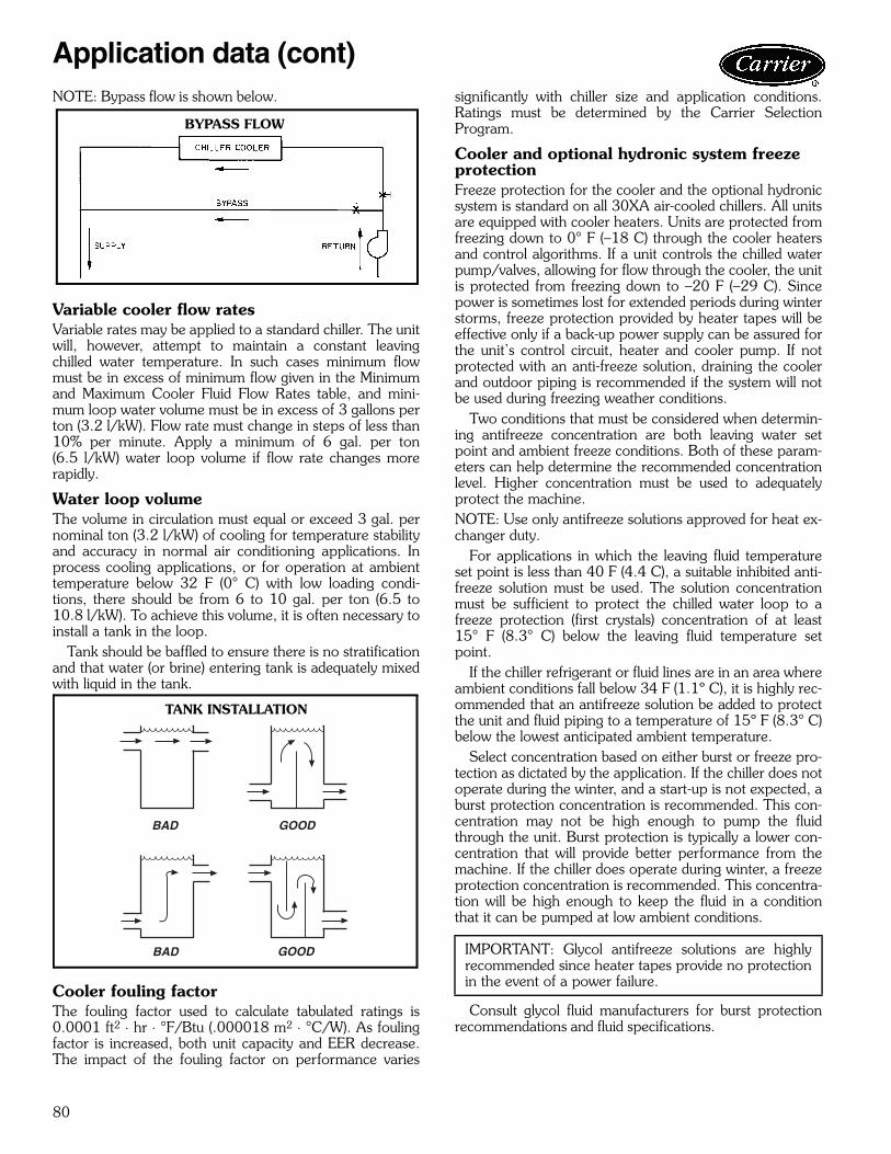
80
NOTE: Bypass flow is shown below.
Variable cooler flow ratesVariable rates may be applied to a standard chiller. The unitwill, however, attempt to maintain a constant leavingchilled water temperature. In such cases minimum flowmust be in excess of minimum flow given in the Minimumand Maximum Cooler Fluid Flow Rates table, and mini-mum loop water volume must be in excess of 3 gallons perton (3.2 l/kW). Flow rate must change in steps of less than10% per minute. Apply a minimum of 6 gal. per ton(6.5 l/kW) water loop volume if flow rate changes morerapidly.
Water loop volumeThe volume in circulation must equal or exceed 3 gal. pernominal ton (3.2 l/kW) of cooling for temperature stabilityand accuracy in normal air conditioning applications. Inprocess cooling applications, or for operation at ambienttemperature below 32 F (0° C) with low loading condi-tions, there should be from 6 to 10 gal. per ton (6.5 to10.8 l/kW). To achieve this volume, it is often necessary toinstall a tank in the loop.
Tank should be baffled to ensure there is no stratificationand that water (or brine) entering tank is adequately mixedwith liquid in the tank.
Cooler fouling factorThe fouling factor used to calculate tabulated ratings is0.0001 ft2 ⋅ hr ⋅ °F/Btu (.000018 m2 ⋅ °C/W). As foulingfactor is increased, both unit capacity and EER decrease.The impact of the fouling factor on performance varies
significantly with chiller size and application conditions.Ratings must be determined by the Carrier SelectionProgram.
Cooler and optional hydronic system freeze protectionFreeze protection for the cooler and the optional hydronicsystem is standard on all 30XA air-cooled chillers. All unitsare equipped with cooler heaters. Units are protected fromfreezing down to 0° F (–18 C) through the cooler heatersand control algorithms. If a unit controls the chilled waterpump/valves, allowing for flow through the cooler, the unitis protected from freezing down to –20 F (–29 C). Sincepower is sometimes lost for extended periods during winterstorms, freeze protection provided by heater tapes will beeffective only if a back-up power supply can be assured forthe unit’s control circuit, heater and cooler pump. If notprotected with an anti-freeze solution, draining the coolerand outdoor piping is recommended if the system will notbe used during freezing weather conditions.
Two conditions that must be considered when determin-ing antifreeze concentration are both leaving water setpoint and ambient freeze conditions. Both of these param-eters can help determine the recommended concentrationlevel. Higher concentration must be used to adequatelyprotect the machine.NOTE: Use only antifreeze solutions approved for heat ex-changer duty.
For applications in which the leaving fluid temperatureset point is less than 40 F (4.4 C), a suitable inhibited anti-freeze solution must be used. The solution concentrationmust be sufficient to protect the chilled water loop to afreeze protection (first crystals) concentration of at least15° F (8.3° C) below the leaving fluid temperature setpoint.
If the chiller refrigerant or fluid lines are in an area whereambient conditions fall below 34 F (1.1º C), it is highly rec-ommended that an antifreeze solution be added to protectthe unit and fluid piping to a temperature of 15º F (8.3° C)below the lowest anticipated ambient temperature.
Select concentration based on either burst or freeze pro-tection as dictated by the application. If the chiller does notoperate during the winter, and a start-up is not expected, aburst protection concentration is recommended. This con-centration may not be high enough to pump the fluidthrough the unit. Burst protection is typically a lower con-centration that will provide better performance from themachine. If the chiller does operate during winter, a freezeprotection concentration is recommended. This concentra-tion will be high enough to keep the fluid in a conditionthat it can be pumped at low ambient conditions.
Consult glycol fluid manufacturers for burst protectionrecommendations and fluid specifications.
BYPASS FLOW
a30-533
BAD
BAD
GOOD
GOOD
TANK INSTALLATION
a30-3185 IMPORTANT: Glycol antifreeze solutions are highlyrecommended since heater tapes provide no protectionin the event of a power failure.
Application data (cont)
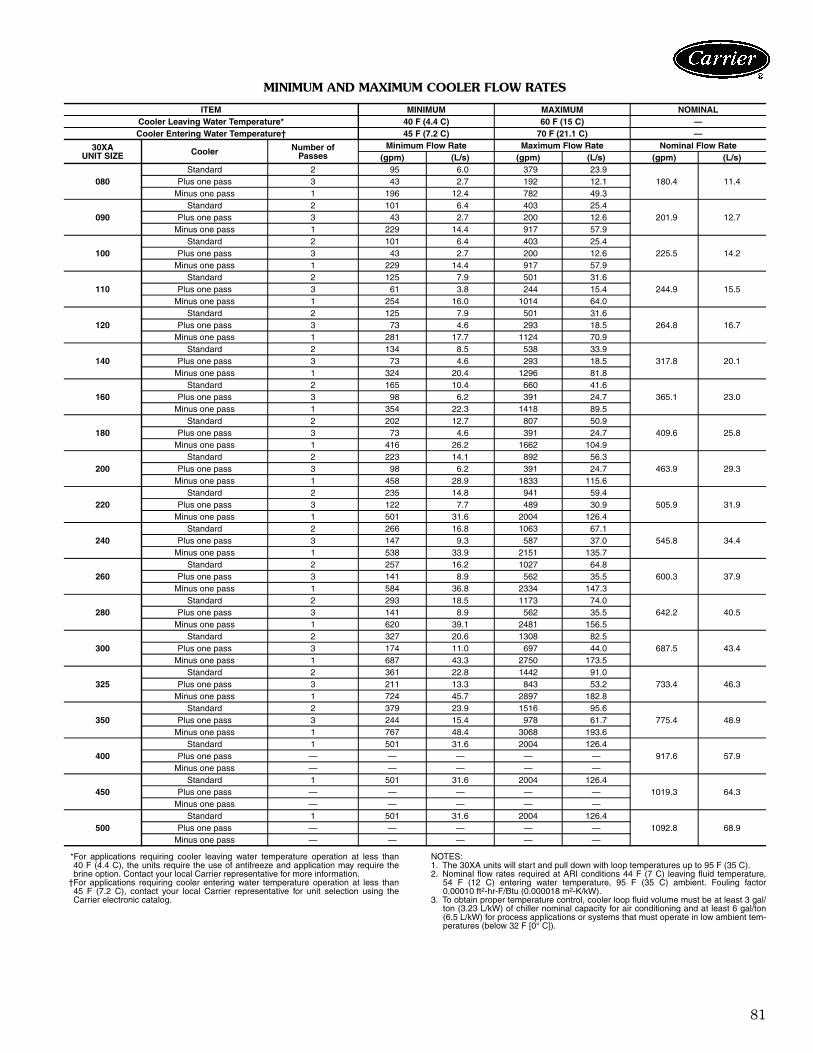
81
MINIMUM AND MAXIMUM COOLER FLOW RATES
*For applications requiring cooler leaving water temperature operation at less than40 F (4.4 C), the units require the use of antifreeze and application may require thebrine option. Contact your local Carrier representative for more information.
†For applications requiring cooler entering water temperature operation at less than45 F (7.2 C), contact your local Carrier representative for unit selection using theCarrier electronic catalog.
NOTES: 1. The 30XA units will start and pull down with loop temperatures up to 95 F (35 C).2. Nominal flow rates required at ARI conditions 44 F (7 C) leaving fluid temperature,
54 F (12 C) entering water temperature, 95 F (35 C) ambient. Fouling factor0.00010 ft2-hr-F/Btu (0.000018 m2-K/kW).
3. To obtain proper temperature control, cooler loop fluid volume must be at least 3 gal/ton (3.23 L/kW) of chiller nominal capacity for air conditioning and at least 6 gal/ton(6.5 L/kW) for process applications or systems that must operate in low ambient tem-peratures (below 32 F [0° C]).
ITEM MINIMUM MAXIMUM NOMINALCooler Leaving Water Temperature* 40 F (4.4 C) 60 F (15 C) —Cooler Entering Water Temperature† 45 F (7.2 C) 70 F (21.1 C) —
30XAUNIT SIZE Cooler Number of
PassesMinimum Flow Rate Maximum Flow Rate Nominal Flow Rate
(gpm) (L/s) (gpm) (L/s) (gpm) (L/s)
080Standard 2 95 6.0 379 23.9
180.4 11.4Plus one pass 3 43 2.7 192 12.1Minus one pass 1 196 12.4 782 49.3
090Standard 2 101 6.4 403 25.4
201.9 12.7Plus one pass 3 43 2.7 200 12.6Minus one pass 1 229 14.4 917 57.9
100Standard 2 101 6.4 403 25.4
225.5 14.2Plus one pass 3 43 2.7 200 12.6Minus one pass 1 229 14.4 917 57.9
110Standard 2 125 7.9 501 31.6
244.9 15.5Plus one pass 3 61 3.8 244 15.4Minus one pass 1 254 16.0 1014 64.0
120Standard 2 125 7.9 501 31.6
264.8 16.7Plus one pass 3 73 4.6 293 18.5Minus one pass 1 281 17.7 1124 70.9
140Standard 2 134 8.5 538 33.9
317.8 20.1Plus one pass 3 73 4.6 293 18.5Minus one pass 1 324 20.4 1296 81.8
160Standard 2 165 10.4 660 41.6
365.1 23.0Plus one pass 3 98 6.2 391 24.7Minus one pass 1 354 22.3 1418 89.5
180Standard 2 202 12.7 807 50.9
409.6 25.8Plus one pass 3 73 4.6 391 24.7Minus one pass 1 416 26.2 1662 104.9
200Standard 2 223 14.1 892 56.3
463.9 29.3Plus one pass 3 98 6.2 391 24.7Minus one pass 1 458 28.9 1833 115.6
220Standard 2 235 14.8 941 59.4
505.9 31.9Plus one pass 3 122 7.7 489 30.9Minus one pass 1 501 31.6 2004 126.4
240Standard 2 266 16.8 1063 67.1
545.8 34.4Plus one pass 3 147 9.3 587 37.0Minus one pass 1 538 33.9 2151 135.7
260Standard 2 257 16.2 1027 64.8
600.3 37.9Plus one pass 3 141 8.9 562 35.5Minus one pass 1 584 36.8 2334 147.3
280Standard 2 293 18.5 1173 74.0
642.2 40.5Plus one pass 3 141 8.9 562 35.5Minus one pass 1 620 39.1 2481 156.5
300Standard 2 327 20.6 1308 82.5
687.5 43.4Plus one pass 3 174 11.0 697 44.0Minus one pass 1 687 43.3 2750 173.5
325Standard 2 361 22.8 1442 91.0
733.4 46.3Plus one pass 3 211 13.3 843 53.2Minus one pass 1 724 45.7 2897 182.8
350Standard 2 379 23.9 1516 95.6
775.4 48.9Plus one pass 3 244 15.4 978 61.7Minus one pass 1 767 48.4 3068 193.6
400Standard 1 501 31.6 2004 126.4
917.6 57.9Plus one pass — — — — —Minus one pass — — — — —
450Standard 1 501 31.6 2004 126.4
1019.3 64.3Plus one pass — — — — —Minus one pass — — — — —
500Standard 1 501 31.6 2004 126.4
1092.8 68.9Plus one pass — — — — —Minus one pass — — — — —
82
High ambient temperature operationHigh outdoor ambient chiller start-up and operation is pos-sible for standard 30XA chillers at ambient temperaturesup to 125 F (52 C) at nominal voltage. For applicationsapproaching these temperatures, it may be advisable toselect the high ambient temperature option to increase fanairflow. Further, the high ambient temperature option isrequired for 30XA400-500 chillers under the followingcircumstances:• ambient temperatures at or above 100 F (37.8 C)• multi-chiller configurations.
Low ambient temperature operationUnits will start and operate down to 32 F (0° C) asstandard. Operation to –20 F (–29 C) requires optionallow ambient head pressure control as well as wind baffles(field fabricated and installed to all units for operationbelow 32 F [0° C]) if wind velocity is anticipated to begreater than 5 mph (8 km/h). Inhibited propylene glycol orother suitable corrosion-resistant antifreeze solution mustbe field supplied and installed in all units for unit operationbelow 34 F (1.1 C). Solution must be added to fluid loop toprotect loop down to 15° F (8.3° C) below minimum oper-ating ambient temperature. Concentration should be basedon expected minimum temperature and either “Burst” or“Freeze” protection levels. At least 6 gal. per ton(6.5 l/kW) of water volume is the recommended minimumfor a moderate system load.
Altitude correction factorsCorrection factors must be applied to standard ratingsat altitudes above 2000 ft (609.6 m) using the followingmultipliers:
ALTITUDE CORRECTION FACTORS
Condenser airflow — Airflow restrictions on units withstandard fans will affect the unit capacity, condenser headpressure, and compressor power input. Correction factorsto be applied for external static restrictions up to 0.2 in. wg(50 Pa) are as follows:
Multiple chillersWhere multiple chillers are required, or where standbycapability is desired, chillers may be installed in parallel.Units may be of the same size or different sizes. However,cooler flow rates must be balanced according to the recom-mendations for each chiller to ensure proper flow.
Unit software is capable of controlling two units as a sin-gle plant. Refer to the Controls, Start-Up, Operation, Ser-vice, and Troubleshooting guide for further details.
Dual chiller controlThe ComfortLink™ controller allows 2 chillers (piped inparallel or series) to operate as a single chilled water plantwith standard control functions coordinated through themaster chiller controller. This standard ComfortLink fea-ture requires a communication link between the 2 chillers.There are several advantages to this type of control:• Redundancy (multiple circuits)• Better low load control (lower tonnage capability)• Lower rigging lift weights (2 machines rather than
1 large machine)• Chiller lead-lag operation (evens the wear between the
two machines)Parallel dual chiller operation — Parallel chiller opera-tion is the recommended option for dual chiller control. Inthis case, each chiller must control its own dedicated pumpor isolation valve. Balancing valves are recommended toensure proper flow in each chiller. Two field-supplied andinstalled leaving water temperature sensors are required,one for each module, for this function to operate properly.The hardware required to accomplish this dual-chiller coor-dination is available as a field-installed accessory.
Consider adding additional isolation valves to isolateeach chiller to allow for service on a machine, and stillallow for partial capacity from the other chiller.Series dual chiller operation — Series chiller operationis an alternate control method supported by theComfortLink control system. Certain applications mightrequire that the two chillers be connected in series. Fornominal 10° F (5.6° C) cooler ranges, use the Minus 1Pass Cooler arrangement to reduce the fluid-side pressuredrop. Use the standard cooler pass arrangement for lowflow, high cooler temperature rise applications. Two field-supplied and installed dual chiller leaving water tempera-ture sensors are required, one for each module, for thisfunction to operate properly.
Consider adding additional piping and isolation valves toisolate each chiller to allow for service on a machine, andstill allow for partial capacity from the other chiller.
Condenser coil protection (Enviro-Shield™)Refer to the environmental selection guides for more infor-mation. If the standard Novation® (microchannel) coil doesnot meet the corrosion requirements for a given applica-tion, additional coil options are available. For specific geo-graphical recommendations, please refer to the NACOPackaged Chiller Builder program.Aluminum fin/copper tube coils are constructed ofseamless copper tubes mechanically bonded to aluminumfins. The fins have wavy enhancements. These condensercoils are recommended with remote cooler applications.These coils are not recommended for corrosive environ-ments.Pre-coated aluminum-fin coils have a durableepoxyphenolic coating applied to the fin prior to the finstamping process to provide protection in mildly corrosivecoastal environments. Pre-coated coils have an inert bar-rier between the aluminum fin and copper tube. This bar-rier electrically disconnects the dissimilar metals tominimize the potential for galvanic corrosion. This
ALTITUDE CAPACITYMULTIPLIER
COMPRESSOR POWERMULTIPLIER(ft) (m)
2,000 609.6 0.99 1.014,000 1219.2 0.98 1.026,000 1828.8 0.97 1.038,000 2438.4 0.96 1.04
10,000 3048 0.95 1.05
EXTERNAL STATIC CAPACITYMULTIPLIER
COMPRESSORPOWER MULTIPLIERin. wg Pa
0.0 0.0 1.000 1.000.1 25 0.986 1.010.2 50 0.968 1.03
Application data (cont)
83
economical option provides substantial corrosion protec-tion beyond the standard uncoated coil construction.Copper-fin coils provide increased corrosion resistancecompared to aluminum fin coils. All-copper coils eliminatebimetallic construction to eliminate the potential for gal-vanic corrosion. Application in industrial environments isnot recommended due to potential attack from sulfur, sul-fur oxide, nitrogen oxides, carbon and several other indus-trial airborne contaminants.E-coated Novation® coils have an extremely flexibleand durable epoxy coating uniformly applied to all coil sur-faces. Unlike brittle phenolic dip and bake coatings, e-coatprovides superior protection with unmatched flexibility,edge coverage, metal adhesion, thermal performance andmost importantly, corrosion resistance. E-coated coils
provide this protection since all coil surfaces are complete-ly encapsulated from environmental contamination. Thisoption provides the best protection for Novation coiltechnology.E-coated aluminum-fin coils have the same flexible anddurable epoxy coating as e-coated Novation coils. This op-tion provides better protection compared to standard orprecoated aluminum-fin coils in many environments.E-coated copper-fin coils have the same flexible anddurable epoxy coating as other e-coated coils. However,this option combines the natural salt and environmental re-sistance of all-copper construction with the highest level ofcorrosion protection within the round-tube, plate-fin typeof coils.
SLAVE CHILLER
CONTROLBOX
PUMP
MASTER CHILLER
CONTROLBOX
DUAL CHILLERLWT SENSORS
& WELLS
SLAVE CHILLER
CONTROLBOX
PUMP & CHECK VALVEMASTER CHILLER
CONTROLBOX
DUAL CHILLERLWT SENSORS
& WELLS
OR ISOLATION VALVE
PUMP & CHECK VALVE
OR ISOLATION VALVE
PARALLEL DUAL CHILLER OPERATION
SERIES DUAL CHILLER OPERATION
LEGENDLWT — Leaving Water Temperature
Field-Installed Communication BusField-Installed Wiring
LEGENDLWT — Leaving Water Temperature
Field-Installed Communication BusField-Installed Wiring
a30-4453
a30-4116
84
Optional hydronic system selectionSelect pump flow from resulting chiller selection and totalpressure loss in the system plus the chiller internal pressureloss.NOTE: Maximum flow (gpm [L/s]), pressure and pump hpmust not exceed maximum indicated on pump curve.
Pump flow can be reduced by using the factory-suppliedcombination valve up to 10%. Beyond that, impeller trim-ming is recommended to reduce energy consumption. Fol-low local codes or ASHRAE 90.1 recommendations.Contact your Carrier representative for the specificamount of trim required.
The AquaForce® 30XA chiller will require a field-supplied expansion tank when the optional pump packageis provided.
The expansion tank is based on fluid type, temperaturerange, fluid pressure and loop volume.
Parallel chillers with hydronic packages require thatpump inlets be equalized to prevent pump cavitation. Ifmore than one expansion tank is to be used in the chillerwater loop, the expansion tanks must be located togetherin the common pump suction header. If expansion tankrelocation is required for parallel chiller configuration, allmaterials needed for expansion tank relocation are fieldsupplied. Appropriate measures must be taken for freezeprotection.NOTE: It is recommended for units with the hydronicpackage that an inlet isolation (shutoff) valve be placedexterior to the unit to allow removal and service of theentire pump assembly, if necessary. The hydronic packageis supplied from the factory with a combination valve forisolation of leaving water. Also, if the unit is isolated withvalves, a properly sized pressure relief valve is recom-mended and should be installed in the piping between theunit and the valves, following all applicable local codes.
Air separationFor proper system operation, it is essential that waterloops be installed with proper means to manage air in thesystem. Free air in the system can cause noise, reduce ter-minal output, stop flow, or even cause pump failure due topump cavitation. For closed systems, equipment should beprovided to eliminate all air from the system.
The amount of air that water can hold in solutiondepends on the pressure and temperature of the water/airmixture. Air is less soluble at higher temperatures and atlower pressures. Therefore, separation can best be done atthe point of highest water temperature and lowest pres-sure. Typically, this point would be on the suction side ofthe pump as the water is returning from the system or ter-minals. This is generally the optimal place to install an airseparator, if possible.
Install automatic air vents at all high points in the system.(If the 30XA unit is located at the high point of the system,a vent can be installed on the piping leaving the heatexchanger on the 1/4 in. NPT female port.)
Install an air separator in the water loop, at the placewhere the water is at higher temperatures and lower pres-sures — usually in the chilled water return piping. On a pri-mary-secondary system, the highest temperature water isnormally in the secondary loop, close to the decoupler.Preference should be given to that point on the system. In-line or centrifugal air separators are readily available in thefield.
It may not be possible to install air separators at theplace of the highest temperature and lowest pressure. Insuch cases, preference should be given to the points ofhighest temperature. It is important that the pipe be sizedcorrectly so that free air can be moved to the point of sepa-ration. Generally, a water velocity of at least 2 feet per sec-ond (0.6 m per second) will keep free air entrained andprevent it from forming air pockets.
Automatic vents should be installed at all physically ele-vated points in the system so that air can be eliminated dur-ing system operation. Provisions should also be made formanual venting during the water loop fill.
Electrical/utility interestsEnergy management — Use of energy managementpractices can significantly reduce operating costs, espe-cially during off-peak modes of operation. Demand limitingand temperature reset are two techniques for accomplish-ing efficient energy management. See Demand Limiting(also called load shedding) section below for further details.
Demand limiting (load shedding)When a utility’s demand for electricity exceeds a certainlevel, loads are shed to keep electricity demand below aprescribed maximum level. Typically, this happens on hotdays when air conditioning is most needed. The energymanagement module (EMM) can be added to accomplishthis reduction. Demand may be limited on the unit by reset-ting water temperature, or by unloading the chiller to agiven predetermined percentage of the load. Demand limitmay also be driven by an external 4 to 20 mA signal.These features require a signal from an intelligentcentral control. Do not cycle demand limiter for less than10 minutes on and 5 minutes off. Duty cycling cycles elec-trical loads at regular intervals regardless of need. Thisreduces the electrical operating costs of building by “fool-ing” demand indicating devices. Duty cycling of compres-sors or fans is not recommended since motor winding andbearing life will suffer from constant cycling.
Remote on-off controlRemote on-off control may be applied by hard-wired con-nection (see Controls and Troubleshooting literature) or byconnection to the Carrier Comfort Network® (CCN)system.
IMPORTANT: Automatic vents should be located inaccessible locations for maintenance purposes and pro-tected from freezing.
Application data (cont)

85
Minimum time to power chiller beforestart-upIn order to ensure that the oil sump heaters are providedsufficient time to raise the oil sump temperature to therequired operating point, power must be applied to thecontrol circuit a minimum or 24 hours prior to chiller
start-up. On 30XA chillers, the control circuit obtains itspower either from a direct 115-V, single-phase powersource or from an optional control transformer on themain 3-phase power supply. The control circuit powersource must be energized at least 24 hours prior to chillerstart-up.
86
Air-Cooled Liquid ChillerHVAC Guide SpecificationsSize Range: 80 to 500 Tons, Nominal (265 to 1615 kW, Nominal)Carrier Model Number: 30XAPart 1 — General1.01 SYSTEM DESCRIPTION
Microprocessor controlled, air-cooled liquid chillerutilizing screw compressors and low sound fans.
1.02 QUALITY ASSURANCEA. Unit shall be rated in accordance with ARI Standard
550/590 (U.S.A.) latest edition and all units shall beASHRAE 90.1 compliant.
B. Unit construction shall comply with ASHRAE 15Safety Code, UL 1995, and ASME applicable codes(U.S.A. codes).
C. Unit shall be manufactured in a facility registered toISO 9001:2000 Manufacturing Quality Standard.
D. Unit shall be full load run tested at the factory.1.03 DELIVERY, STORAGE AND HANDLING
A. Unit controls shall be capable of with-standing 150 F (65.5 C) storage temperatures in thecontrol compartment.
B. Unit shall be stored and handled per unit manufac-turer’s recommendations.
Part 2 — Products2.01 EQUIPMENT
A. General:Factory assembled, single-piece chassis, air-cooledliquid chiller. Contained within the unit cabinet shallbe all factory wiring, piping, controls, refrigerantcharge (R-134a), and special features required priorto field start-up.
B. Unit Cabinet:1. Frame shall be of heavy-gage, painted galva-
nized steel.2. Cabinet shall be galvanized steel casing with a
baked enamel powder or pre-painted finish.3. Cabinet shall be capable of withstanding
500-hour salt spray test in accordance with theASTM (U.S.A.) B-117 standard.
C. Fans:1. Condenser fans shall be direct-driven, 9-blade
airfoil cross-section, reinforced polymer con-struction, shrouded-axial type, and shall be stat-ically and dynamically balanced with inherentcorrosion resistance.
2. Air shall be discharged vertically upward.3. Fans shall be protected by coated steel wire
safety guards.D. Compressor/Compressor Assembly:
1. Comprised of semi-hermetic twin screw typecompressors.
2. Compressor motor shall be direct drive,3500 rpm, protected by motor temperaturesensors, suction gas cooled motor.
3. Capacity control shall utilize an infinitely modu-lating slide valve to modulate capacity from100% to 15% full load.
E. Cooler:1. Shall be a mechanically cleanable tubes in a
shell-and-tube type cooler with removableheads.
2. Tubes shall be internally enhanced seamless-copper type rolled into tube sheets.
3. Shall be equipped with Victaulic-type waterconnections.
4. Shell and cooler heads shall be insulated with3/4-in. PVC foam (closed-cell) with a maximumK factor of 0.28.
5. Design shall incorporate a minimum of 2 or 3independent refrigerant circuits.
6. Cooler shall be tested and stamped in accor-dance with ASME Code for a refrigerant work-ing side pressure of 220 psig. Cooler shall havea maximum water-side pressure of 300 psig.
7. Cooler shall have a cooler drain and vent.8. Low-ambient temperature protection: unit shall
have factory-installed cooler heater, andpumpout cycle to protect cooler from ambienttemperature freeze down to 0° F (–17.8 C).
9. Cooler shall be provided with a factory-installedflow switch.
F. Condenser:1. Coil shall be air-cooled Novation® heat
exchanger technology (MCHX) and shall have aseries of flat tubes containing a series of multi-ple, parallel flow microchannels layeredbetween the refrigerant manifolds. Novationcoils shall consist of a two-pass arrangement.Coil construction shall consist of aluminumalloys for fins, tubes, and manifolds in combina-tion with a corrosion-resistant coating.
2. Tubes shall be cleaned, dehydrated, and sealed.3. Assembled condenser coils shall be leak tested
and pressure tested at 375 psig (2585 kPa).G. Refrigeration Components:
Refrigerant circuit components shall includereplaceable-core filter drier, moisture indicating sightglass, electronic expansion valve, discharge servicevalves and liquid line service valves, and completeoperating charge of both refrigerant R-134a andcompressor oil.
H. Controls, Safeties, and Diagnostics:1. Unit controls shall include the following mini-
mum components:a. Microprocessor with non-volatile memory.
Battery backup system shall not be accepted.
Guide specifications
87
b. Separate terminal block for power andcontrols.
c. Separate 115-v power supply to serve allcontrollers, relays, and control components.
d. ON/OFF control switch.e. Replaceable solid-state controllers.f. Pressure sensors installed to measure suc-
tion, oil, economizer, and discharge pressure.Thermistors installed to measure coolerentering and leaving fluid temperatures andoutside air temperature.
2. Unit controls shall include the followingfunctions:a. Automatic circuit lead/lag.b. Capacity control based on leaving chilled
fluid temperature and compensated by rateof change of return-fluid temperature withtemperature set point accuracy to 0.1° F(0.05° C).
c. Limiting the chilled fluid temperature pull-down rate at start-up to an adjustable range of0.2° F to 2° F (0.1 to 1.1° C) per minute toprevent excessive demand spikes at start-up.
d. Seven-day time schedule.e. Leaving chilled fluid temperature reset from
return fluid and outside air temperature.f. Chilled water pump start/stop control.g. Chiller control for parallel chiller applications
without addition of hardware modules andcontrol panels (requires thermistors).
h. Timed maintenance scheduling to signalmaintenance activities for strainer mainte-nance and user-defined maintenanceactivities.
i. Low ambient protection to energize coolerheaters.
j. Single step demand limit control activated byremote contact closure.
3. Diagnostics:a. The control panel shall include, as standard,
a display:1) Touch screen display consisting of 1/4
VGA LCD (liquid crystal display) withadjustable contrast and backlighting.
2) Display shall allow a user to navigatethrough menus, select desired optionsand modify data.
b. Features of the display shall include:1) Display shall be customizable and allow
up to 72 data points.2) Display shall support both local equip-
ment or network made for remotemount.
3) Display shall allow access to configura-tion, maintenance, service, set point,
time schedules, alarm history and statusdata.
4) Display shall have one button for chilleron/off.
5) Display shall include three levels ofpassword protection against unautho-rized access to configuration andmaintenance information, and displayset up parameters.
6) Display shall allow for easy connectionof a portable hand held technician toolto access information and upload and/or download chiller settings.
7) Display shall be compatible with theCarrier Comfort Network® (CCN) sys-tem and provide network alarmacknowledgement or indication andprovide capability to fully monitor andcontrol chiller.
8) Display alarms and parameters shall becapable of being displayed in full text.
9) Display shall be capable of displayingthe last 50 alarms and will store a snap-shot of a minimum of 20 status dataparameters for each alarm.
10) Compressor run hours.11) Compressor number of starts.12) Compressor current.13) Time of day:
a) Display module, in conjunction withthe microprocessor, must also becapable of displaying the output(results) of a service test. Service testshall verify operation of everyswitch, thermistor, fan, and com-pressor before chiller is started.
b) Diagnostics shall include the abilityto review a list of the 30 most recentalarms with clear language descrip-tions of the alarm event. Display ofalarm codes without the ability forclear language descriptions shall beprohibited.
c) An alarm history buffer shall allowthe user to store no less than30 alarm events with clear languagedescriptions, time and date stampevent entry.
d) The chiller controller shall includemultiple connection ports for com-municating with the local equipmentnetwork, the Carrier Comfort Net-work (CCN) system and the ability toaccess all chiller control functionsfrom any point on the chiller.
e) The control system shall allow soft-ware upgrade without the need fornew hardware modules.
4. Safeties:a. Unit shall be equipped with thermistors and
all necessary components in conjunction
88
with the control system to provide the unitwith the following protections:
1) Loss of refrigerant charge.2) Reverse rotation.3) Low chilled fluid temperature.4) Motor overtemperature.5) High pressure.6) Electrical overload.7) Loss of phase.8) Loss of chilled water flow.
b. Condenser-fan motors shall have internalovercurrent protection.
I. Operating Characteristics:1. Unit shall be capable of starting and running at
outdoor ambient temperatures from 32 F (0° C)to 125 F (52 C) for all sizes.
2. Unit shall be capable of starting up with 95 F(35 C) entering fluid temperature to the cooler.
J. Motors:Condenser-fan motors shall be totally enclosed, airover, single speed, 3-phase type with permanentlylubricated bearings and Class F insulation.
K. Electrical Requirements:1. Unit primary electrical power supply shall enter
the unit at a single location (all chiller voltage/size combinations shall have the ability toaccommodate 2 power supplies to meet job-specific requirements).
2. Primary electrical power supply shall be ratedto operate up to 125 F (52 C) ambienttemperature.
3. Unit shall operate on 3-phase power at the volt-age shown in the equipment schedule.
4. Control points shall be accessed through termi-nal block.
5. Unit shall be shipped with factory control andpower wiring installed.
L. Chilled Water Circuit:1. Chilled water circuit shall be rated for 300 psig
(2068 kPa). Units with optional pump packageare rated for 150 psig (1034 kPa) workingpressure.
2. Thermal dispersion proof of flow switch shall befactory installed and wired.
3. Optional hydronic package (sizes 090-160):a. Field pipe connections shall be Victaulic
type.b. Optional single or primary/stand-by opera-
tion pump systems. Dual pump systems shallhave a pump discharge check valve.
c. Pumps shall be single stage design, for instal-lation in vertical position and capable ofbeing serviced without disturbing pipingconnections.1) Pump casing shall be of class 30 cast
iron.
2) The impeller shall be of cast bronze,closed type, dynamically balanced,keyed to the shaft and secured by lock-ing cap screw.
3) The hydronic kit will be provided witha flush line connection to ensure lubrica-tion at the seal face and allow forpositive venting of the seal chamber.
4) Each port shall be fitted with an isolationvalve that allow the units to operate inparallel or standby, yet may be used toisolate one pumping unit for servicing orremoval with the other pump stillrunning.
5) Pump shall be rated for 150 psig(1034 kPa) working pressure.
6) The pump case shall have gage tappingsat the suction and discharge nozzles andinclude drain ports.
7) Dual pumps shall allow for the servicingof one pump without draining the chilledwater loop.
8) Motors shall totally enclosed 3-phasetype with grease lubricated ball bearings.
9) Each pump shall be factory tested perHydraulic Institute Standards.
d. Pressure/temperature taps (3) shall befactory installed to measure the pressuredifferential across the pump and across thestrainer.
e. Combination valve shall be factory installed.Pressure/temperature taps (2) shall befactory installed to measure the pressuredifferential across the combination valve.
f. Hydronic assembly shall have factorysupplied electric freeze protection to –20 F(–29 C).
g. Piping shall be Schedule 40 black steel.h. Cast iron or ductile iron body strainer with 8
mesh screen. A factory-installed, removablefine mesh clean-out strainer for initial runperiod shall be included.
M. Special Features:Certain standard features are not applicablewhen the features designated by * are specified. Forassistance in amending the specifications, contactyour Carrier representative.
* 1. Low Ambient Temperature Head PressureControl:Unit shall be capable of running at outdoorambient temperatures down to –20 F (–29 C)with the addition of antifreeze in the cooler cir-cuit, wind baffles, and field-installed or factory-installed solid-state low ambient temperaturehead pressure control with condenser coil tem-perature sensor.
Guide specifications (cont)
89
2. Unit-Mounted Non-Fused Disconnect:Unit shall be supplied with factory-installed,lockable, non-fused electrical disconnect formain power supply.
3. Optional Condenser Coil Materials:a. E-coated microchannel coils:
E-coated aluminum microchannel coil shallhave a flexible epoxy polymer coating uni-formly applied to all coil external surfaceareas without material bridging between finsor louvers. Coating process shall ensurecomplete coil encapsulation, including allexposed fin edges. E-coat shall have a thick-ness of 0.8 to 1.2 mil with top coat having auniform dry film thickness from 1.0 to 2.0mil on all external coil surface areas includ-ing fin edges. E-coated coils shall have supe-rior hardness characteristics of 2H perASTM D3363-00 and cross hatch adhesionof 4B-5B per ASTM D3359-02. Impactresistance shall be up to 160 in./lb (ASTMD2794-93). E-coated coil shall have superiorimpact resistance with no cracking, chip-ping, or peeling per NSF/ANSI 51-2002Method 10.2.
b. Aluminum fin/copper-tube coils:Coil shall be constructed of seamless coppertubes mechanically bonded to aluminum fins.fins shall have wavy enhancements. Thesecondenser coils are recommended withremote cooler applications. These coils arenot recommended for corrosive environ-ments.
c. Pre-coated aluminum-fin coils:Shall have a durable epoxy-phenolic coatingto provide protection in mildly corrosivecoastal environments. Coating shall beapplied to the aluminum fin stock prior to thefin stamping process to create an inert bar-rier between the aluminum fin and coppertube. Epoxy-phenolic barrier shall minimizegalvanic action between dissimilar metals.
d. Copper-fin coils:Shall be constructed of copper fins mechani-cally bonded to copper tubes and coppertube sheets. Galvanized steel tube sheetsshall not be acceptable. A polymer strip shallprevent coil assembly from contacting sheetmetal coil pan to minimize potential for gal-vanic corrosion between the coil and pan.All copper construction shall provide protec-tion in moderate coastal applications.
e. E-coated aluminum-fin coils:Shall have a flexible epoxy polymer coatinguniformly applied to all coil surface areaswithout material bridging between fins.Coating process shall ensure complete coilencapsulation. Color shall be high gloss
black with gloss — 60° of 65-90% perASTM D523-89. Uniform dry film thicknessfrom 0.8 to 1.2 mil on all surface areasincluding fin edges. Superior hardness char-acteristics of 2H per ASTM D3363-92Aand cross hatch adhesion of 4B-5B perASTM D3359-93. Impact resistance shall beup to 160 in./lb (ASTM D2794-93). Humid-ity and water immersion resistance shall beup to minimum 1000 and 250 hours respec-tively (ASTM D2247-92 and ASTM D870-92). Corrosion durability shall be confirmedthrough testing to no less than 3000 hourssalt spray per ASTM B117-90. Coil con-struction shall be aluminum fins mechani-cally bonded to copper tubes.
f. E-coated copper-fin coils:Shall have a flexible epoxy polymer coatinguniformly applied to all coil surface areaswithout material bridging between fins.Coating process shall ensure complete coilencapsulation. Color shall be high glossblack with gloss — 60° of 65-90% perASTM D523-89. Uniform dry film thicknessfrom 0.8 to 1.2 mil on all surface areasincluding fin edges. Superior hardnesscharacteristics of 2H per ASTM D3363-92A and cross hatch adhesion of 4B-5B perASTM D3359-93. Impact resistance shall beup to 160 in./lb (ASTM D2794-93). Humid-ity and water immersion resistance shall beup to minimum 1000 and 250 hours respec-tively (ASTM D2247-92 and ASTM D870-92). Corrosion durability shall be confirmedthrough testing to no less than 3000 hourssalt spray per ASTM B117-90. Coil con-struction shall be copper-fins mechanicallybonded to copper tube sheets. Galvanizedsteel tube sheets shall not be acceptable. Apolymer strip shall prevent coil assemblyfrom contacting sheet metal coil pan tomaintain coating integrity and minimize cor-rosion potential between the coil and pan.
4. Remote Enhanced Display:Unit shall be supplied with indoor-mounted,remote, 40-character per line, 16-line displaypanel for field installation.
5. Medium Temperature Brine (080-350 only):Unit shall be factory modified to start and oper-ate at leaving chilled fluid temperatures below30 F (–1.1 C).
6. Energy Management Module:A factory or field-installed module shall providethe following energy management capabilities:4 to 20 mA signals for leaving fluid temperaturereset, cooling set point reset or demand limitcontrol; 2-step demand limit control (from 0%to 100%) activated by a remote contact closure;
90
and discrete input for “Ice Done” indication forice storage system interface.
7. Condenser Coil Trim Panels:Unit shall be supplied with field-installed coilcovers.
8. BACnet™ Translator Control:Unit shall be supplied with field-installed inter-face between the chiller and a BACnet LocalArea Network (LAN, i.e., MS/TP EIA-485).
9. LON Translator Control:Unit shall be supplied with field-installed inter-face between the chiller and a Local OperatingNetwork (LON, i.e., LonWorks FT-10A ANSI/EIA-709.1).
10. Navigator™ hand held portable display:a. Portable hand held display module with a
minimum of 4 lines and 20 characters perline, or clear English, Spanish, Portugueseor French language.
b. Display menus shall provide clear languagedescriptions of all menu items, operatingmodes, configuration points and alarm diag-nostics. Reference to factory codes shall notbe accepted.
c. RJ-14 connection plug shall allow displaymodule to be connected to factory-installedreceptacle.
d. Industrial grade coiled extension cord shallallow the display module to be movedaround the chiller.
e. Magnets shall hold the display module to anysheet metal panel to allow hands-free opera-tion.
f. Display module shall have NEMA 4x hous-ing suitable for use in outdoor environments.
g. Display shall have back light and contrastadjustment for easy viewing in bright sun-light or night conditions.
h. Raised surface buttons with positive tactileresponse.
11. Touch Pilot™ display:Unit shall be supplied with a remote mounttouch screen display for network attachment tothe chiller.
12. Compressor Suction Service Valve:Standard refrigerant discharge isolation and liq-uid valves enable service personnel to store therefrigerant charge in the cooler or condenserduring servicing. This factory-installed optionallows for further isolation of the compressorfrom the cooler vessel.
13. Suction Line Insulation:Insulation is tubular closed-cell insulation. Thisoption is required with the medium temperaturebrine option and recommended for areas of
high dewpoints where condensation may be aconcern.
14. Service Option:The service option provides a remote serviceport for Navigator™ connection and a factory-installed convenience outlet that includes4-amp GFI (Ground Fault Interrupt) receptaclewith independent fuse protection. Convenienceoutlet is 115-v female receptacle. Serviceoption not available with 380 v.
15. Remote Service Port:Shall be a field-installed receptacle for Naviga-tor device connection.
16. Wye-Delta Starter:Unit shall have a factory-installed, wye-deltastart to minimize electrical inrush current.
17. Control Transformer:Unit shall be supplied with a factory-installedtransformer that will allow supply control circuitpower from the main unit power supply.
18. GFI Convenience Outlet:Shall be factory or field-installed and mountedwith easily accessible 115-v female receptacle.Shall include 4 amp GFI receptacle.
19. Plus-One-Pass Cooler:Unit shall be equipped with plus-one-passcooler heads to be used with low temperaturebrine options or high delta T application.
20. Minus-One-Pass Cooler:Unit shall be equipped with minus-one-passcooler heads with reduced water-side pressuredrop for series flow dual chiller control or highchilled water flow applications.
21. High Ambient Temperature:Unit shall be equipped with high speed con-denser fan motors to improve performance athigh ambient temperatures. This option shall berequired for 30XA400-500 chillers which areoperating in multi-chiller configurations or haveambient temperatures at or above 100 F(37.8 C).
22. Security Grilles:Unit shall be provided with factory (or field)installed painted grilles to protect the con-denser, cooler and compressor.
23. Upper Hail Guard:Unit shall be equipped with a factory-installedoption consisting of louvered panels on theends of the machine which firmly fasten to themachine frame. These panels shall cover theunit from the top to the bottom of the coils,thus providing protection of the coils from haildamage.
24. Full Hail Guard:Unit shall be equipped with field-installed acces-sory consisting of hinged, louvered panels,
Guide specifications (cont)
91
which cover both ends of the unit. This acces-sory provides complete protection from hail.
25. Full End Screen:Unit shall be equipped with a factory-installedoption consisting of louvered panels that coverthe machine ends from top to bottom andfirmly fasten to the machine frame. These endscreens function as a privacy screen and alsoprovide hail protection.
26. Low Sound Package:Unit shall be provided with sound attenuationpackage to include sheet metal enclosures withsound absorbing panels for each compressor.
27. Remote Cooler Kit:Allows remote installation of the cooler.
28. Minimum Load Control:Unit shall be equipped with microprocessor-controlled minimum load control that shall per-mit unit operation below the minimum standardoperation (varies by unit size).
29. External Pump Control:This field-installed accessory shall be required toprovide control of dual, external pumps. Thisaccessory shall not be required for single, exter-nal pumps or factory-installed pumps.
30. Dual Chiller Accessory Kit:For dual chiller applications, unit shall be pro-vided with the additional hardware (thermistors,wells, connectors) required for proper systemoperation.

Manufacturer reserves the right to discontinue, or change at any time, specifications or designs without notice and without incurring obligations. Pg 92 Catalog No. 04-52300013-01 Printed in U.S.A. Form 30XA-5PD
Replaces: 30XA-4PD
Carrier Corporation • Syracuse, New York 13221 809 7-09
Section 9Tab 9b