Embed Size (px)
Citation preview
1
®
FEATURES / BENEFITS
38VTA030• Lighter unit weight for ease of handling• Increased metal embossment for cabinet rigidity• Moulded propeller fan for better air dispersion &
sound quality• Service valves mounted on embossed valve plate
for easier piping installation• Easy access from top & front of the unit for service
& maintenance• One piece back panel to eliminate rattling & for ease
of manufacturing• Compressor compartment insulated ensuring quiet
operation• Flare liquid & suction service valves ensures fast &
easy installation & servicing• Equipped with Rotary compressor for smooth &
energy efficient operation• A fan guard built for polypropylene - UV protection
additive & offers quick access and easymaintenance
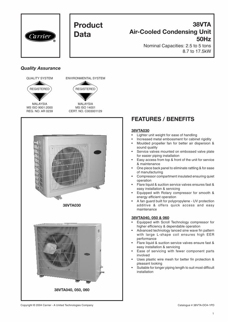
38VTA040, 050 & 060• Equipped with Scroll Technology compressor for
higher efficiency & dependable operation• Advanced technology lanced sine wave fin pattern
with large L-shape coil ensures high EERperformance
• Flare liquid & suction service valves ensure fast &easy installation & servicing
• Ease of servicing with fewer component partsinvolved
• Uses plastic wire mesh for better fin protection &pleasant looking
• Suitable for longer piping length to suit most difficultinstallation
38VTA030
38VTA040, 050, 060
®
38VTAAir-Cooled Condensing Unit
50HzNominal Capacities: 2.5 to 5 tons
8.7 to 17.5kW
ProductData
Quality Assurance
REGISTERED
QUALITY SYSTEM
MALAYSIAMS ISO 9001:2000REG. NO. AR 0239
REGISTERED
ENVIRONMENTAL SYSTEM
MALAYSIAMS ISO 14001
CERT. NO. C003001129
Copyright © 2004 Carrier - A United Technologies Company Catalogue # 38VTA-DO4-1PD
2
®
TABLE OF CONTENTS PAGE
Features & Benefits .......................................................................................................................1Specifications ................................................................................................................................2Unit Dimensions ............................................................................................................................3Selection Procedure ......................................................................................................................4Electrical Data ...............................................................................................................................4Wiring Diagrams ........................................................................................................................... 5System Wiring Connections ......................................................................................................... 6 - 13System Cooling Capacities ........................................................................................................... 14- 20CDU Performance Rating ............................................................................................................. 21 - 22Guide Specification ....................................................................................................................... 23
SPECIFICATIONS
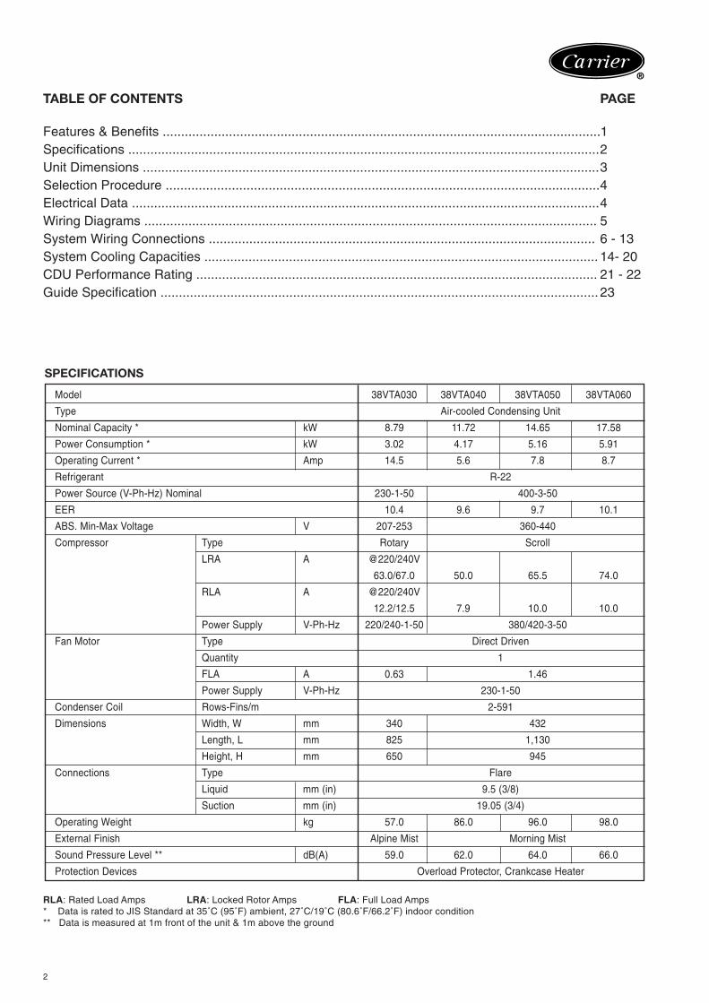
Model 38VTA030 38VTA040 38VTA050 38VTA060
Type Air-cooled Condensing Unit
Nominal Capacity * kW 8.79 11.72 14.65 17.58
Power Consumption * kW 3.02 4.17 5.16 5.91
Operating Current * Amp 14.5 5.6 7.8 8.7
Refrigerant R-22
Power Source (V-Ph-Hz) Nominal 230-1-50 400-3-50
EER 10.4 9.6 9.7 10.1
ABS. Min-Max Voltage V 207-253 360-440
Compressor Type Rotary Scroll
LRA A @220/240V
63.0/67.0 50.0 65.5 74.0
RLA A @220/240V
12.2/12.5 7.9 10.0 10.0
Power Supply V-Ph-Hz 220/240-1-50 380/420-3-50
Fan Motor Type Direct Driven
Quantity 1
FLA A 0.63 1.46
Power Supply V-Ph-Hz 230-1-50
Condenser Coil Rows-Fins/m 2-591
Dimensions Width, W mm 340 432
Length, L mm 825 1,130
Height, H mm 650 945
Connections Type Flare
Liquid mm (in) 9.5 (3/8)
Suction mm (in) 19.05 (3/4)
Operating Weight kg 57.0 86.0 96.0 98.0
External Finish Alpine Mist Morning Mist
Sound Pressure Level ** dB(A) 59.0 62.0 64.0 66.0
Protection Devices Overload Protector, Crankcase Heater
RLA: Rated Load Amps LRA: Locked Rotor Amps FLA: Full Load Amps* Data is rated to JIS Standard at 35˚C (95˚F) ambient, 27˚C/19˚C (80.6˚F/66.2˚F) indoor condition** Data is measured at 1m front of the unit & 1m above the ground
3
®
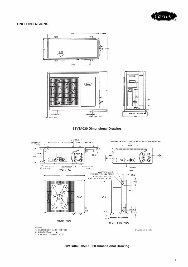
UNIT DIMENSIONS
38VTA030 Dimensional Drawing
38VTA040, 050 & 060 Dimensional Drawing
NOTES:1. DIMENSIONS IN () ARE 1 FEET-INCH2. AIR DIRECTION3. FOOT-PRINT 0.58M (6.02 SQ. FT)
Drawings not to scale
4
®
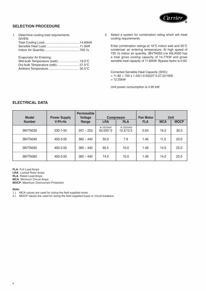
SELECTION PROCEDURE
1. Determine cooling load requirementsGIVEN:Total Cooling Load.........................................14.60kWSensible Heat Load.......................................11.5kWIndoor Air Quantity.........................................700 l/s
Evaporator Air Entering:Wet-bulb Temperature (ewb).........................19.0°CDry-bulb Temperature (edb).......................... 27.5°CAmbient Temperature................................... 30.5°C
2. Select a system for combination rating which will meetcooling requirements.
Enter combination ratings at 19°C indoor ewb and 35°Ccondenser air entering temperature. At high speed of720 l/s indoor air quantity, 38VTA050 c/w 40LX050 hasa total gross cooling capacity of 14.77kW and grosssensible heat capacity of 11.82kW. Bypass factor is 0.03.
Corrected Sensible Heat Capacity (SHC):= 11.82 + 720 x 1.23(1-0.03)(27.5-27.0)/1000= 12.25kW
Unit power consumption is 4.95 kW
ELECTRICAL DATA
PermissibleModel Power Supply Voltage Compressor Fan Motor Unit
Number V-Ph-Hz Range LRA RLA FLA MCA MOCP
38VTA030 230-1-50 207 ~ 253 63.0/67.0 12.2/12.5 0.63 16.0 30.0
38VTA040 400-3-50 360 ~ 440 50.0 7.9 1.46 11.0 20.0
38VTA050 400-3-50 360 ~ 440 65.5 10.0 1.46 14.0 25.0
38VTA060 400-3-50 360 ~ 440 74.0 10.0 1.46 14.0 25.0
FLA: Full Load AmpsLRA: Locked Rotor AmpsRLA: Rated Load AmpsMCA: Minimum Circuit AmpsMOCP: Maximum Overcurrent Protection
Note:1.) MCA values are used for sizing the field supplied wires.2.) MOCP values are used for sizing the field supplied fuses or circuit breakers.
@ 220/240V @ 220/240V
5
®
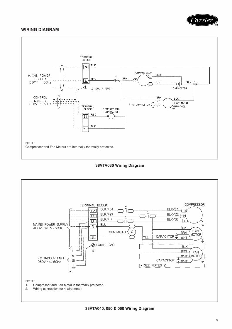
WIRING DIAGRAM
38VTA030 Wiring Diagram
38VTA040, 050 & 060 Wiring Diagram
NOTE:1. Compressor and Fan Motor is thermally protected.2. Wiring connection for 4 wire motor.
NOTE:Compressor and Fan Motors are internally thermally protected.
6
®
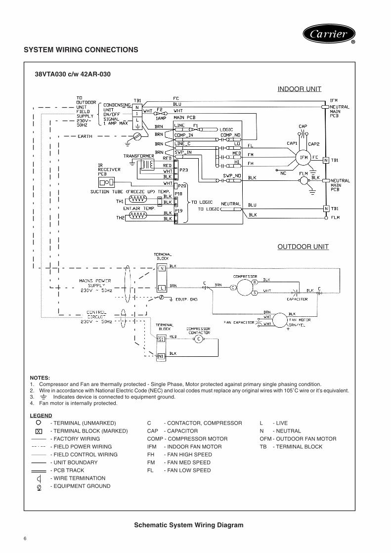
SYSTEM WIRING CONNECTIONS
Schematic System Wiring Diagram
38VTA030 c/w 42AR-030
INDOOR UNIT
OUTDOOR UNIT
NOTES:1. Compressor and Fan are thermally protected - Single Phase, Motor protected against primary single phasing condition.2. Wire in accordance with National Electric Code (NEC) and local codes must replace any original wires with 105˚C wire or it’s equivalent.3. Indicates device is connected to equipment ground.4. Fan motor is internally protected.
LEGEND- TERMINAL (UNMARKED) C - CONTACTOR, COMPRESSOR L - LIVE
- TERMINAL BLOCK (MARKED) CAP - CAPACITOR N - NEUTRAL
- FACTORY WIRING COMP - COMPRESSOR MOTOR OFM - OUTDOOR FAN MOTOR
- FIELD POWER WIRING IFM - INDOOR FAN MOTOR TB - TERMINAL BLOCK
- FIELD CONTROL WIRING FH - FAN HIGH SPEED
- UNIT BOUNDARY FM - FAN MED SPEED
- PCB TRACK FL - FAN LOW SPEED
- WIRE TERMINATION
- EQUIPMENT GROUND
X
7
®
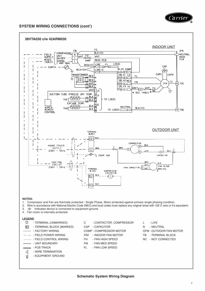
SYSTEM WIRING CONNECTIONS (cont’)
Schematic System Wiring Diagram
38VTA030 c/w 42ARM030
INDOOR UNIT
OUTDOOR UNIT
NOTES:1. Compressor and Fan are thermally protected - Single Phase, Motor protected against primary single phasing condition.2. Wire in accordance with National Electric Code (NEC) and local codes must replace any original wires with 105˚C wire or it’s equivalent.3. Indicates device is connected to equipment ground.4. Fan motor is internally protected.
LEGEND- TERMINAL (UNMARKED) C - CONTACTOR, COMPRESSOR L - LIVE
- TERMINAL BLOCK (MARKED) CAP - CAPACITOR N - NEUTRAL
- FACTORY WIRING COMP - COMPRESSOR MOTOR OFM - OUTDOOR FAN MOTOR
- FIELD POWER WIRING IFM - INDOOR FAN MOTOR TB - TERMINAL BLOCK
- FIELD CONTROL WIRING FH - FAN HIGH SPEED NC - NOT CONNECTED
- UNIT BOUNDARY FM - FAN MED SPEED
- PCB TRACK FL - FAN LOW SPEED
- WIRE TERMINATION
- EQUIPMENT GROUND
X
8
®
SYSTEM WIRING CONNECTIONS (cont’)
Schematic System Wiring Diagram
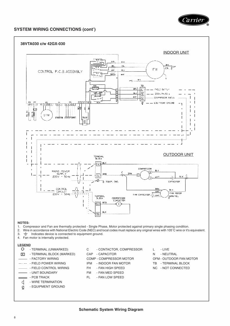
38VTA030 c/w 42GX-030
INDOOR UNIT
OUTDOOR UNIT
NOTES:1. Compressor and Fan are thermally protected - Single Phase, Motor protected against primary single phasing condition.2. Wire in accordance with National Electric Code (NEC) and local codes must replace any original wires with 105˚C wire or it’s equivalent.3. Indicates device is connected to equipment ground.4. Fan motor is internally protected.
LEGEND- TERMINAL (UNMARKED) C - CONTACTOR, COMPRESSOR L - LIVE
- TERMINAL BLOCK (MARKED) CAP - CAPACITOR N - NEUTRAL
- FACTORY WIRING COMP - COMPRESSOR MOTOR OFM - OUTDOOR FAN MOTOR
- FIELD POWER WIRING IFM - INDOOR FAN MOTOR TB - TERMINAL BLOCK
- FIELD CONTROL WIRING FH - FAN HIGH SPEED NC - NOT CONNECTED
- UNIT BOUNDARY FM - FAN MED SPEED
- PCB TRACK FL - FAN LOW SPEED
- WIRE TERMINATION
- EQUIPMENT GROUND
X
9
®
SYSTEM WIRING CONNECTIONS (cont’)
Schematic System Wiring Diagram
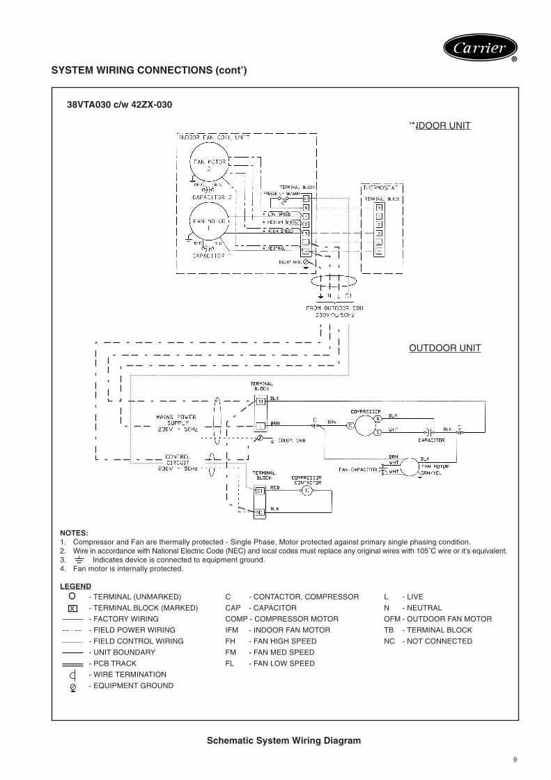
38VTA030 c/w 42ZX-030
INDOOR UNIT
OUTDOOR UNIT
NOTES:1. Compressor and Fan are thermally protected - Single Phase, Motor protected against primary single phasing condition.2. Wire in accordance with National Electric Code (NEC) and local codes must replace any original wires with 105˚C wire or it’s equivalent.3. Indicates device is connected to equipment ground.4. Fan motor is internally protected.
LEGEND- TERMINAL (UNMARKED) C - CONTACTOR, COMPRESSOR L - LIVE
- TERMINAL BLOCK (MARKED) CAP - CAPACITOR N - NEUTRAL
- FACTORY WIRING COMP - COMPRESSOR MOTOR OFM - OUTDOOR FAN MOTOR
- FIELD POWER WIRING IFM - INDOOR FAN MOTOR TB - TERMINAL BLOCK
- FIELD CONTROL WIRING FH - FAN HIGH SPEED NC - NOT CONNECTED
- UNIT BOUNDARY FM - FAN MED SPEED
- PCB TRACK FL - FAN LOW SPEED
- WIRE TERMINATION
- EQUIPMENT GROUND
X
10
®
SYSTEM WIRING CONNECTIONS (cont’)
Schematic System Wiring Diagram
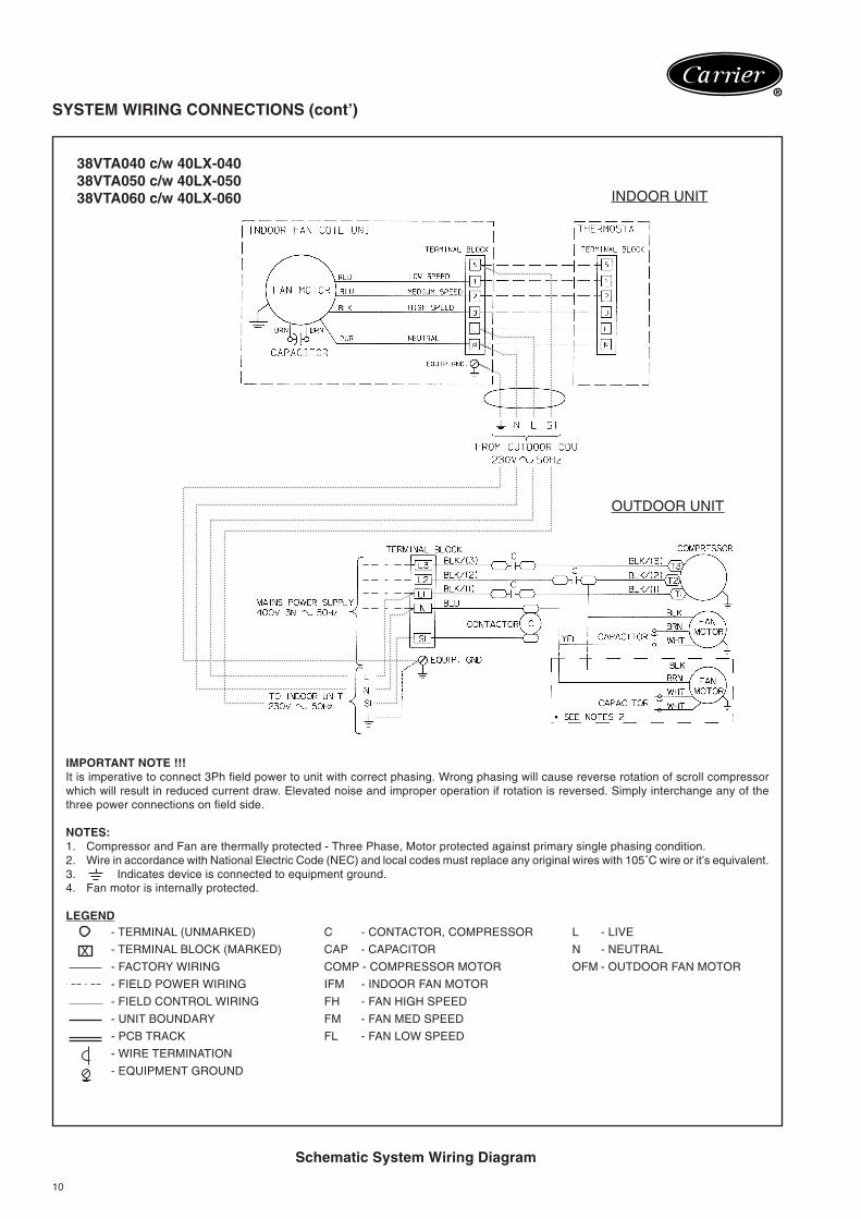
38VTA040 c/w 40LX-04038VTA050 c/w 40LX-05038VTA060 c/w 40LX-060 INDOOR UNIT
OUTDOOR UNIT
IMPORTANT NOTE !!!It is imperative to connect 3Ph field power to unit with correct phasing. Wrong phasing will cause reverse rotation of scroll compressorwhich will result in reduced current draw. Elevated noise and improper operation if rotation is reversed. Simply interchange any of thethree power connections on field side.
NOTES:1. Compressor and Fan are thermally protected - Three Phase, Motor protected against primary single phasing condition.2. Wire in accordance with National Electric Code (NEC) and local codes must replace any original wires with 105˚C wire or it’s equivalent.3. Indicates device is connected to equipment ground.4. Fan motor is internally protected.
LEGEND- TERMINAL (UNMARKED) C - CONTACTOR, COMPRESSOR L - LIVE
- TERMINAL BLOCK (MARKED) CAP - CAPACITOR N - NEUTRAL
- FACTORY WIRING COMP - COMPRESSOR MOTOR OFM - OUTDOOR FAN MOTOR
- FIELD POWER WIRING IFM - INDOOR FAN MOTOR
- FIELD CONTROL WIRING FH - FAN HIGH SPEED
- UNIT BOUNDARY FM - FAN MED SPEED
- PCB TRACK FL - FAN LOW SPEED
- WIRE TERMINATION
- EQUIPMENT GROUND
X
11
®
SYSTEM WIRING CONNECTIONS (cont’)
Schematic System Wiring Diagram
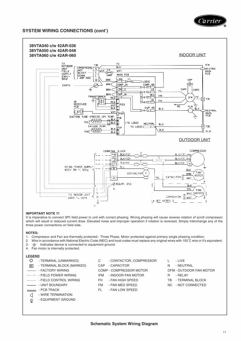
38VTA040 c/w 42AR-03638VTA050 c/w 42AR-04838VTA060 c/w 42AR-060 INDOOR UNIT
OUTDOOR UNIT
IMPORTANT NOTE !!!It is imperative to connect 3Ph field power to unit with correct phasing. Wrong phasing will cause reverse rotation of scroll compressorwhich will result in reduced current draw. Elevated noise and improper operation if rotation is reversed. Simply interchange any of thethree power connections on field side.
NOTES:1. Compressor and Fan are thermally protected - Three Phase, Motor protected against primary single phasing condition.2. Wire in accordance with National Electric Code (NEC) and local codes must replace any original wires with 105˚C wire or it’s equivalent.3. Indicates device is connected to equipment ground.4. Fan motor is internally protected.
LEGEND- TERMINAL (UNMARKED) C - CONTACTOR, COMPRESSOR L - LIVE
- TERMINAL BLOCK (MARKED) CAP - CAPACITOR N - NEUTRAL
- FACTORY WIRING COMP - COMPRESSOR MOTOR OFM - OUTDOOR FAN MOTOR
- FIELD POWER WIRING IFM - INDOOR FAN MOTOR R - RELAY
- FIELD CONTROL WIRING FH - FAN HIGH SPEED TB - TERMINAL BLOCK
- UNIT BOUNDARY FM - FAN MED SPEED NC - NOT CONNECTED
- PCB TRACK FL - FAN LOW SPEED
- WIRE TERMINATION
- EQUIPMENT GROUND
X
12
®
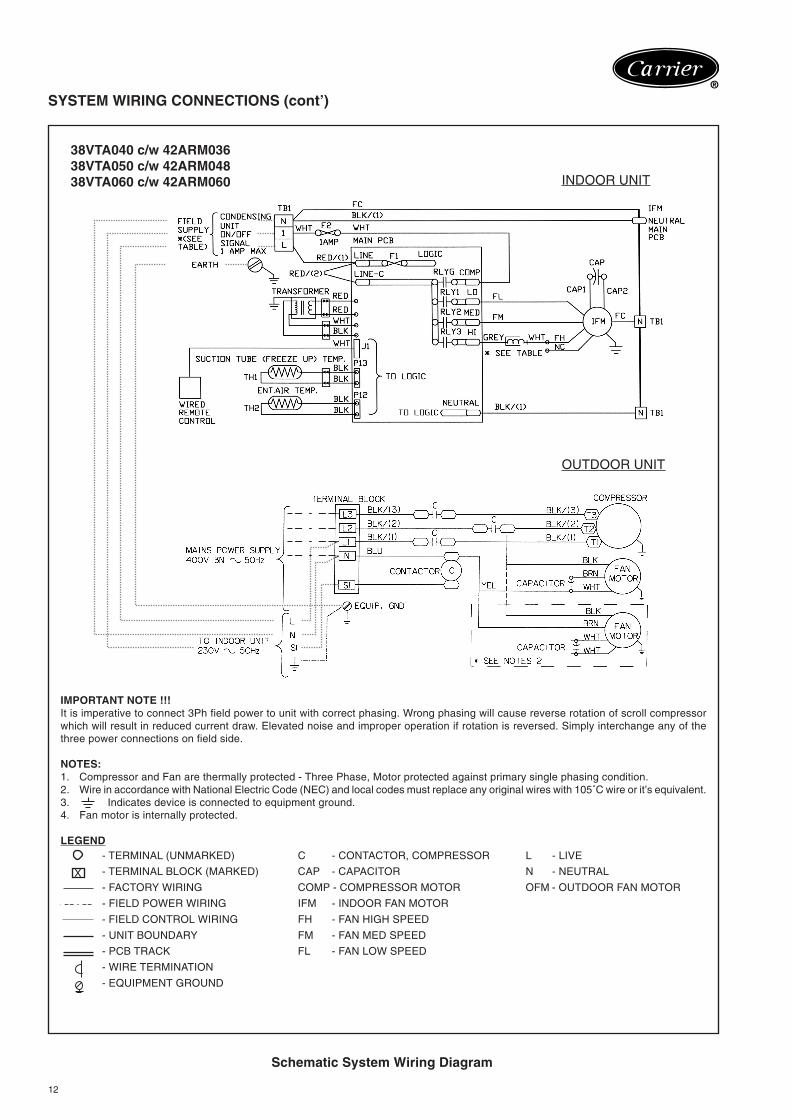
SYSTEM WIRING CONNECTIONS (cont’)
Schematic System Wiring Diagram
38VTA040 c/w 42ARM03638VTA050 c/w 42ARM04838VTA060 c/w 42ARM060 INDOOR UNIT
OUTDOOR UNIT
IMPORTANT NOTE !!!It is imperative to connect 3Ph field power to unit with correct phasing. Wrong phasing will cause reverse rotation of scroll compressorwhich will result in reduced current draw. Elevated noise and improper operation if rotation is reversed. Simply interchange any of thethree power connections on field side.
NOTES:1. Compressor and Fan are thermally protected - Three Phase, Motor protected against primary single phasing condition.2. Wire in accordance with National Electric Code (NEC) and local codes must replace any original wires with 105˚C wire or it’s equivalent.3. Indicates device is connected to equipment ground.4. Fan motor is internally protected.
LEGEND- TERMINAL (UNMARKED) C - CONTACTOR, COMPRESSOR L - LIVE
- TERMINAL BLOCK (MARKED) CAP - CAPACITOR N - NEUTRAL
- FACTORY WIRING COMP - COMPRESSOR MOTOR OFM - OUTDOOR FAN MOTOR
- FIELD POWER WIRING IFM - INDOOR FAN MOTOR
- FIELD CONTROL WIRING FH - FAN HIGH SPEED
- UNIT BOUNDARY FM - FAN MED SPEED
- PCB TRACK FL - FAN LOW SPEED
- WIRE TERMINATION
- EQUIPMENT GROUND
X
13
®
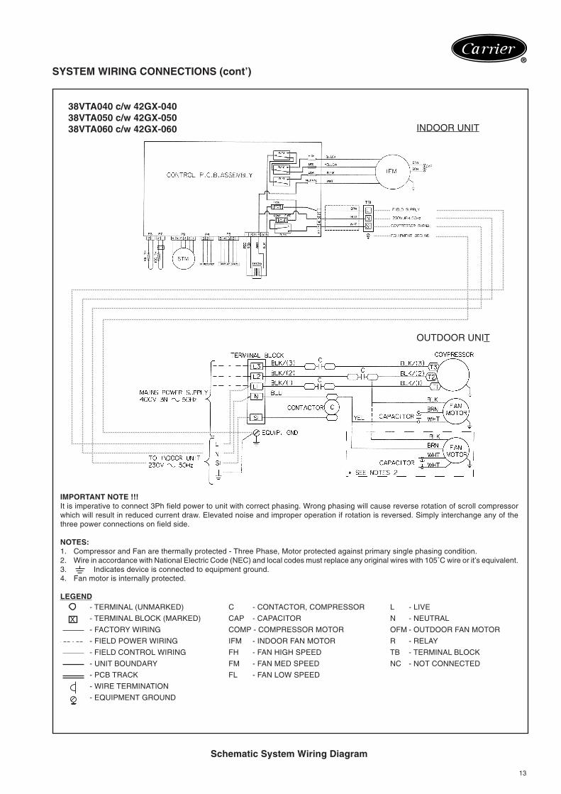
SYSTEM WIRING CONNECTIONS (cont’)
Schematic System Wiring Diagram
38VTA040 c/w 42GX-04038VTA050 c/w 42GX-05038VTA060 c/w 42GX-060 INDOOR UNIT
OUTDOOR UNIT
IMPORTANT NOTE !!!It is imperative to connect 3Ph field power to unit with correct phasing. Wrong phasing will cause reverse rotation of scroll compressorwhich will result in reduced current draw. Elevated noise and improper operation if rotation is reversed. Simply interchange any of thethree power connections on field side.
NOTES:1. Compressor and Fan are thermally protected - Three Phase, Motor protected against primary single phasing condition.2. Wire in accordance with National Electric Code (NEC) and local codes must replace any original wires with 105˚C wire or it’s equivalent.3. Indicates device is connected to equipment ground.4. Fan motor is internally protected.
LEGEND- TERMINAL (UNMARKED) C - CONTACTOR, COMPRESSOR L - LIVE
- TERMINAL BLOCK (MARKED) CAP - CAPACITOR N - NEUTRAL
- FACTORY WIRING COMP - COMPRESSOR MOTOR OFM - OUTDOOR FAN MOTOR
- FIELD POWER WIRING IFM - INDOOR FAN MOTOR R - RELAY
- FIELD CONTROL WIRING FH - FAN HIGH SPEED TB - TERMINAL BLOCK
- UNIT BOUNDARY FM - FAN MED SPEED NC - NOT CONNECTED
- PCB TRACK FL - FAN LOW SPEED
- WIRE TERMINATION
- EQUIPMENT GROUND
X
14
®
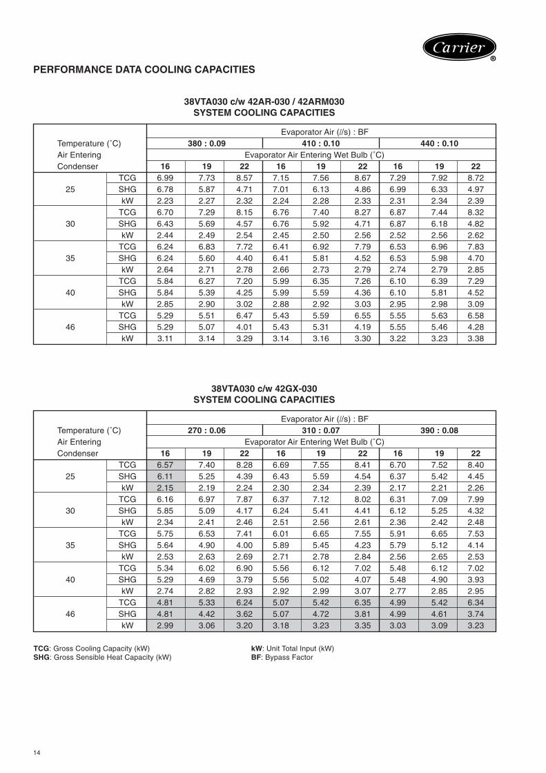
PERFORMANCE DATA COOLING CAPACITIES
38VTA030 c/w 42AR-030 / 42ARM030SYSTEM COOLING CAPACITIES
Evaporator Air (l/s) : BFTemperature (˚C) 380 : 0.09 410 : 0.10 440 : 0.10Air Entering Evaporator Air Entering Wet Bulb (˚C)Condenser 16 19 22 16 19 22 16 19 22
TCG 6.99 7.73 8.57 7.15 7.56 8.67 7.29 7.92 8.7225 SHG 6.78 5.87 4.71 7.01 6.13 4.86 6.99 6.33 4.97
kW 2.23 2.27 2.32 2.24 2.28 2.33 2.31 2.34 2.39TCG 6.70 7.29 8.15 6.76 7.40 8.27 6.87 7.44 8.32
30 SHG 6.43 5.69 4.57 6.76 5.92 4.71 6.87 6.18 4.82kW 2.44 2.49 2.54 2.45 2.50 2.56 2.52 2.56 2.62
TCG 6.24 6.83 7.72 6.41 6.92 7.79 6.53 6.96 7.8335 SHG 6.24 5.60 4.40 6.41 5.81 4.52 6.53 5.98 4.70
kW 2.64 2.71 2.78 2.66 2.73 2.79 2.74 2.79 2.85TCG 5.84 6.27 7.20 5.99 6.35 7.26 6.10 6.39 7.29
40 SHG 5.84 5.39 4.25 5.99 5.59 4.36 6.10 5.81 4.52kW 2.85 2.90 3.02 2.88 2.92 3.03 2.95 2.98 3.09
TCG 5.29 5.51 6.47 5.43 5.59 6.55 5.55 5.63 6.5846 SHG 5.29 5.07 4.01 5.43 5.31 4.19 5.55 5.46 4.28
kW 3.11 3.14 3.29 3.14 3.16 3.30 3.22 3.23 3.38
38VTA030 c/w 42GX-030SYSTEM COOLING CAPACITIES
Evaporator Air (l/s) : BFTemperature (˚C) 270 : 0.06 310 : 0.07 390 : 0.08Air Entering Evaporator Air Entering Wet Bulb (˚C)Condenser 16 19 22 16 19 22 16 19 22
TCG 6.57 7.40 8.28 6.69 7.55 8.41 6.70 7.52 8.4025 SHG 6.11 5.25 4.39 6.43 5.59 4.54 6.37 5.42 4.45
kW 2.15 2.19 2.24 2.30 2.34 2.39 2.17 2.21 2.26TCG 6.16 6.97 7.87 6.37 7.12 8.02 6.31 7.09 7.99
30 SHG 5.85 5.09 4.17 6.24 5.41 4.41 6.12 5.25 4.32kW 2.34 2.41 2.46 2.51 2.56 2.61 2.36 2.42 2.48
TCG 5.75 6.53 7.41 6.01 6.65 7.55 5.91 6.65 7.5335 SHG 5.64 4.90 4.00 5.89 5.45 4.23 5.79 5.12 4.14
kW 2.53 2.63 2.69 2.71 2.78 2.84 2.56 2.65 2.53TCG 5.34 6.02 6.90 5.56 6.12 7.02 5.48 6.12 7.02
40 SHG 5.29 4.69 3.79 5.56 5.02 4.07 5.48 4.90 3.93kW 2.74 2.82 2.93 2.92 2.99 3.07 2.77 2.85 2.95
TCG 4.81 5.33 6.24 5.07 5.42 6.35 4.99 5.42 6.3446 SHG 4.81 4.42 3.62 5.07 4.72 3.81 4.99 4.61 3.74
kW 2.99 3.06 3.20 3.18 3.23 3.35 3.03 3.09 3.23
TCG: Gross Cooling Capacity (kW) kW: Unit Total Input (kW)SHG: Gross Sensible Heat Capacity (kW) BF: Bypass Factor
15
®
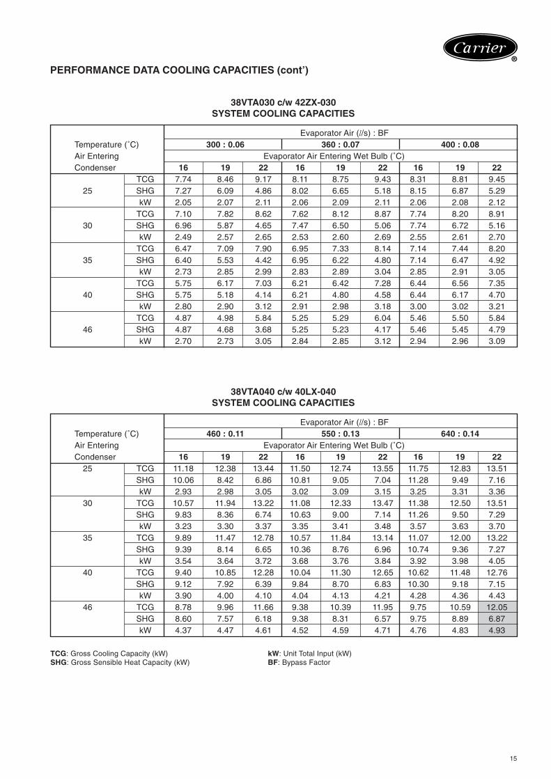
PERFORMANCE DATA COOLING CAPACITIES (cont’)
38VTA030 c/w 42ZX-030SYSTEM COOLING CAPACITIES
Evaporator Air (l/s) : BFTemperature (˚C) 300 : 0.06 360 : 0.07 400 : 0.08Air Entering Evaporator Air Entering Wet Bulb (˚C)Condenser 16 19 22 16 19 22 16 19 22
TCG 7.74 8.46 9.17 8.11 8.75 9.43 8.31 8.81 9.4525 SHG 7.27 6.09 4.86 8.02 6.65 5.18 8.15 6.87 5.29
kW 2.05 2.07 2.11 2.06 2.09 2.11 2.06 2.08 2.12TCG 7.10 7.82 8.62 7.62 8.12 8.87 7.74 8.20 8.91
30 SHG 6.96 5.87 4.65 7.47 6.50 5.06 7.74 6.72 5.16kW 2.49 2.57 2.65 2.53 2.60 2.69 2.55 2.61 2.70
TCG 6.47 7.09 7.90 6.95 7.33 8.14 7.14 7.44 8.2035 SHG 6.40 5.53 4.42 6.95 6.22 4.80 7.14 6.47 4.92
kW 2.73 2.85 2.99 2.83 2.89 3.04 2.85 2.91 3.05TCG 5.75 6.17 7.03 6.21 6.42 7.28 6.44 6.56 7.35
40 SHG 5.75 5.18 4.14 6.21 4.80 4.58 6.44 6.17 4.70kW 2.80 2.90 3.12 2.91 2.98 3.18 3.00 3.02 3.21
TCG 4.87 4.98 5.84 5.25 5.29 6.04 5.46 5.50 5.8446 SHG 4.87 4.68 3.68 5.25 5.23 4.17 5.46 5.45 4.79
kW 2.70 2.73 3.05 2.84 2.85 3.12 2.94 2.96 3.09
38VTA040 c/w 40LX-040SYSTEM COOLING CAPACITIES
Evaporator Air (l/s) : BFTemperature (˚C) 460 : 0.11 550 : 0.13 640 : 0.14Air Entering Evaporator Air Entering Wet Bulb (˚C)Condenser 16 19 22 16 19 22 16 19 22
25 TCG 11.18 12.38 13.44 11.50 12.74 13.55 11.75 12.83 13.51SHG 10.06 8.42 6.86 10.81 9.05 7.04 11.28 9.49 7.16kW 2.93 2.98 3.05 3.02 3.09 3.15 3.25 3.31 3.36
30 TCG 10.57 11.94 13.22 11.08 12.33 13.47 11.38 12.50 13.51SHG 9.83 8.36 6.74 10.63 9.00 7.14 11.26 9.50 7.29kW 3.23 3.30 3.37 3.35 3.41 3.48 3.57 3.63 3.70
35 TCG 9.89 11.47 12.78 10.57 11.84 13.14 11.07 12.00 13.22SHG 9.39 8.14 6.65 10.36 8.76 6.96 10.74 9.36 7.27kW 3.54 3.64 3.72 3.68 3.76 3.84 3.92 3.98 4.05
40 TCG 9.40 10.85 12.28 10.04 11.30 12.65 10.62 11.48 12.76SHG 9.12 7.92 6.39 9.84 8.70 6.83 10.30 9.18 7.15kW 3.90 4.00 4.10 4.04 4.13 4.21 4.28 4.36 4.43
46 TCG 8.78 9.96 11.66 9.38 10.39 11.95 9.75 10.59 12.05SHG 8.60 7.57 6.18 9.38 8.31 6.57 9.75 8.89 6.87kW 4.37 4.47 4.61 4.52 4.59 4.71 4.76 4.83 4.93
TCG: Gross Cooling Capacity (kW) kW: Unit Total Input (kW)SHG: Gross Sensible Heat Capacity (kW) BF: Bypass Factor
16
®
PERFORMANCE DATA COOLING CAPACITIES (cont’)
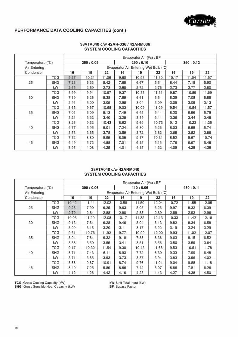
38VTA040 c/w 42AR-036 / 42ARM036SYSTEM COOLING CAPACITIES
Evaporator Air (l/s) : BFTemperature (˚C) 250 : 0.09 290 : 0.10 350 : 0.12Air Entering Evaporator Air Entering Wet Bulb (˚C)Condenser 16 19 22 16 19 22 16 19 22
TCG 9.27 10.21 11.06 9.60 10.58 11.30 10.17 11.04 11.5725 SHG 7.23 6.33 5.42 7.68 6.67 5.54 8.44 7.18 5.90
kW 2.65 2.69 2.73 2.68 2.72 2.76 2.73 2.77 2.80TCG 8.99 9.94 10.97 9.37 10.33 11.31 9.87 10.89 11.69
30 SHG 7.19 6.26 5.38 7.59 6.61 5.54 8.29 7.08 5.85kW 2.91 3.00 3.05 2.98 3.04 3.09 3.05 3.09 3.13
TCG 8.65 9.67 10.68 9.03 10.09 11.09 9.54 10.54 11.5735 SHG 7.01 6.09 5.13 7.49 6.45 5.44 8.20 6.96 5.79
kW 3.21 3.32 3.40 3.28 3.39 3.44 3.36 3.44 3.48TCG 8.26 9.32 10.43 8.62 9.69 10.73 9.12 10.23 11.25
40 SHG 6.77 5.96 5.01 7.24 6.30 5.26 8.03 6.95 5.74kW 3.53 3.65 3.78 3.59 3.72 3.82 3.68 3.82 3.86
TCG 7.72 8.80 9.95 8.05 9.17 10.31 8.52 9.67 10.7446 SHG 6.49 5.72 4.88 7.01 6.15 5.15 7.76 6.67 5.48
kW 3.95 4.08 4.25 4.01 4.15 4.32 4.09 4.25 4.36
38VTA040 c/w 42ARM040SYSTEM COOLING CAPACITIES
Evaporator Air (l/s) : BFTemperature (˚C) 390 : 0.06 410 : 0.06 450 : 0.11Air Entering Evaporator Air Entering Wet Bulb (˚C)Condenser 16 19 22 16 19 22 16 19 22
TCG 10.42 11.44 12.02 10.58 11.50 12.04 10.72 11.55 12.0525 SHG 9.28 7.90 6.25 9.63 8.05 6.26 9.97 8.32 6.39
kW 2.79 2.84 2.88 2.80 2.85 2.89 2.88 2.93 2.96TCG 10.03 11.20 12.08 10.17 11.32 12.13 10.33 11.42 12.18
30 SHG 9.13 7.84 6.28 9.46 8.04 6.43 9.82 8.34 6.58kW 3.09 3.15 3.20 3.11 3.17 3.22 3.19 3.24 3.29
TCG 9.61 10.76 11.92 9.77 10.90 12.00 9.93 11.02 12.0735 SHG 8.94 7.64 6.32 9.18 7.85 6.36 9.63 8.15 6.52
kW 3.38 3.50 3.55 3.41 3.51 3.56 3.50 3.59 3.64TCG 9.17 10.32 11.54 9.30 10.43 11.66 9.53 10.51 11.78
40 SHG 8.71 7.43 6.11 8.93 7.72 6.30 9.33 7.99 6.48kW 3.71 3.85 3.93 3.73 3.87 3.94 3.83 3.96 4.02
TCG 8.56 9.67 10.91 8.74 9.76 11.04 9.04 9.88 11.1846 SHG 8.40 7.25 5.89 8.66 7.42 6.07 8.86 7.81 6.26
kW 4.12 4.26 4.42 4.16 4.28 4.43 4.27 4.38 4.50
TCG: Gross Cooling Capacity (kW) kW: Unit Total Input (kW)SHG: Gross Sensible Heat Capacity (kW) BF: Bypass Factor
17
®
PERFORMANCE DATA COOLING CAPACITIES (cont’)
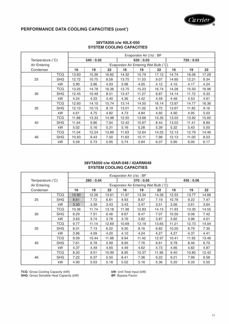
38VTA050 c/w 40LX-050SYSTEM COOLING CAPACITIES
Evaporator Air (l/s) : BFTemperature (˚C) 540 : 0.02 630 : 0.03 720 : 0.03Air Entering Evaporator Air Entering Wet Bulb (˚C)Condenser 16 19 22 16 19 22 16 19 22
TCG 13.83 15.36 16.82 14.32 15.79 17.12 14.74 16.06 17.2925 SHG 12.72 10.75 8.58 13.75 11.53 9.07 14.60 12.21 9.34
kW 3.90 3.96 4.03 3.98 4.05 4.12 4.10 4.17 4.24TCG 13.25 14.78 16.36 13.75 15.23 16.74 14.28 15.50 16.96
30 SHG 12.45 10.49 8.51 13.47 11.27 8.87 14.14 11.72 9.33kW 4.24 4.33 4.40 4.36 4.42 4.49 4.48 4.53 4.61
TCG 12.60 14.10 15.74 13.14 14.50 16.14 13.67 14.77 16.3635 SHG 12.10 10.15 8.19 13.01 11.02 8.72 13.67 11.82 9.16
kW 4.61 4.75 4.82 4.73 4.84 4.92 4.90 4.95 5.03TCG 11.88 13.33 14.98 12.55 13.68 15.35 13.03 13.92 15.60
40 SHG 11.64 9.86 7.94 12.42 10.67 8.44 13.03 11.41 8.89kW 5.02 5.16 5.31 5.16 5.28 5.39 5.32 5.43 5.50
TCG 11.04 12.24 13.89 11.63 12.64 14.25 12.13 12.79 14.4646 SHG 10.93 9.43 7.50 11.63 10.11 7.98 12.13 11.00 8.53
kW 5.59 5.73 5.95 5.74 5.84 6.07 5.90 6.00 6.17
38VTA050 c/w 42AR-048 / 42ARM048SYSTEM COOLING CAPACITIES
Evaporator Air (l/s) : BFTemperature (˚C) 280 : 0.04 370 : 0.05 430 : 0.06Air Entering Evaporator Air Entering Wet Bulb (˚C)Condenser 16 19 22 16 19 22 16 19 22
TCG 10.90 12.26 13.61 11.97 13.34 14.39 12.53 13.77 14.6625 SHG 8.61 7.72 6.81 9.93 8.67 7.19 10.78 9.22 7.47
kW 3.33 3.39 3.43 3.43 3.47 3.51 3.56 3.61 3.64TCG 10.36 11.74 13.18 11.38 12.83 14.15 11.93 13.35 14.55
30 SHG 8.29 7.51 6.46 9.67 8.47 7.07 10.50 9.08 7.42kW 3.63 3.74 3.78 3.76 3.82 3.87 3.92 3.96 4.01
TCG 9.77 11.14 12.69 10.69 12.19 13.65 11.21 12.73 14.0435 SHG 8.01 7.13 6.22 9.30 8.16 6.82 10.20 8.79 7.30
kW 3.96 4.09 4.20 4.10 4.24 4.27 4.27 4.37 4.41TCG 9.09 10.44 11.98 9.94 11.42 12.97 10.41 11.92 13.46
40 SHG 7.61 6.78 5.99 8.95 7.76 6.61 9.78 8.46 6.70kW 4.37 4.49 4.65 4.49 4.62 4.73 4.66 4.82 4.87
TCG 8.20 9.51 10.99 8.95 10.37 11.96 9.40 10.80 12.4246 SHG 7.22 6.37 5.50 8.41 7.36 6.22 9.21 7.99 6.58
kW 4.90 5.03 5.18 5.02 5.16 5.36 5.20 5.33 5.50
TCG: Gross Cooling Capacity (kW) kW: Unit Total Input (kW)SHG: Gross Sensible Heat Capacity (kW) BF: Bypass Factor
18
®
PERFORMANCE DATA COOLING CAPACITIES (cont’)
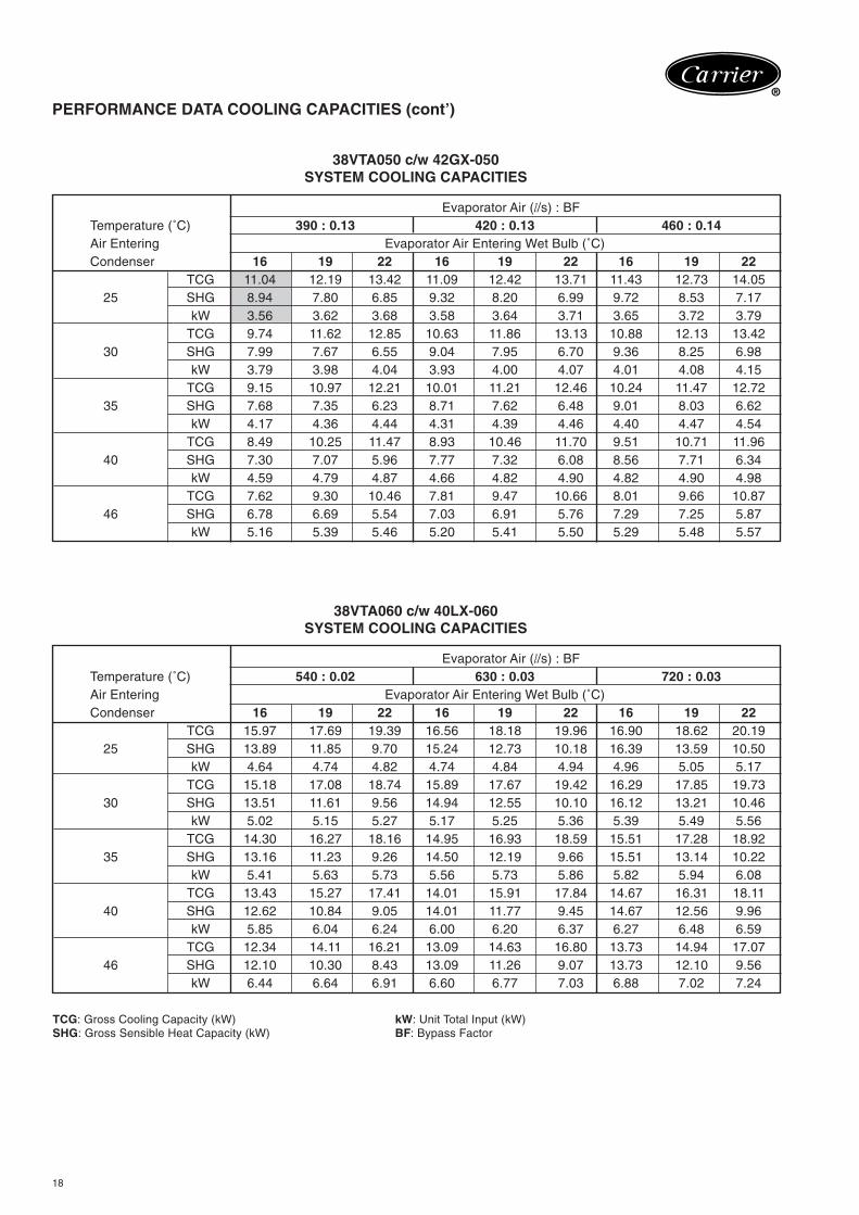
38VTA050 c/w 42GX-050SYSTEM COOLING CAPACITIES
Evaporator Air (l/s) : BFTemperature (˚C) 390 : 0.13 420 : 0.13 460 : 0.14Air Entering Evaporator Air Entering Wet Bulb (˚C)Condenser 16 19 22 16 19 22 16 19 22
TCG 11.04 12.19 13.42 11.09 12.42 13.71 11.43 12.73 14.0525 SHG 8.94 7.80 6.85 9.32 8.20 6.99 9.72 8.53 7.17
kW 3.56 3.62 3.68 3.58 3.64 3.71 3.65 3.72 3.79TCG 9.74 11.62 12.85 10.63 11.86 13.13 10.88 12.13 13.42
30 SHG 7.99 7.67 6.55 9.04 7.95 6.70 9.36 8.25 6.98kW 3.79 3.98 4.04 3.93 4.00 4.07 4.01 4.08 4.15
TCG 9.15 10.97 12.21 10.01 11.21 12.46 10.24 11.47 12.7235 SHG 7.68 7.35 6.23 8.71 7.62 6.48 9.01 8.03 6.62
kW 4.17 4.36 4.44 4.31 4.39 4.46 4.40 4.47 4.54TCG 8.49 10.25 11.47 8.93 10.46 11.70 9.51 10.71 11.96
40 SHG 7.30 7.07 5.96 7.77 7.32 6.08 8.56 7.71 6.34kW 4.59 4.79 4.87 4.66 4.82 4.90 4.82 4.90 4.98
TCG 7.62 9.30 10.46 7.81 9.47 10.66 8.01 9.66 10.8746 SHG 6.78 6.69 5.54 7.03 6.91 5.76 7.29 7.25 5.87
kW 5.16 5.39 5.46 5.20 5.41 5.50 5.29 5.48 5.57
38VTA060 c/w 40LX-060SYSTEM COOLING CAPACITIES
Evaporator Air (l/s) : BFTemperature (˚C) 540 : 0.02 630 : 0.03 720 : 0.03Air Entering Evaporator Air Entering Wet Bulb (˚C)Condenser 16 19 22 16 19 22 16 19 22
TCG 15.97 17.69 19.39 16.56 18.18 19.96 16.90 18.62 20.1925 SHG 13.89 11.85 9.70 15.24 12.73 10.18 16.39 13.59 10.50
kW 4.64 4.74 4.82 4.74 4.84 4.94 4.96 5.05 5.17TCG 15.18 17.08 18.74 15.89 17.67 19.42 16.29 17.85 19.73
30 SHG 13.51 11.61 9.56 14.94 12.55 10.10 16.12 13.21 10.46kW 5.02 5.15 5.27 5.17 5.25 5.36 5.39 5.49 5.56
TCG 14.30 16.27 18.16 14.95 16.93 18.59 15.51 17.28 18.9235 SHG 13.16 11.23 9.26 14.50 12.19 9.66 15.51 13.14 10.22
kW 5.41 5.63 5.73 5.56 5.73 5.86 5.82 5.94 6.08TCG 13.43 15.27 17.41 14.01 15.91 17.84 14.67 16.31 18.11
40 SHG 12.62 10.84 9.05 14.01 11.77 9.45 14.67 12.56 9.96kW 5.85 6.04 6.24 6.00 6.20 6.37 6.27 6.48 6.59
TCG 12.34 14.11 16.21 13.09 14.63 16.80 13.73 14.94 17.0746 SHG 12.10 10.30 8.43 13.09 11.26 9.07 13.73 12.10 9.56
kW 6.44 6.64 6.91 6.60 6.77 7.03 6.88 7.02 7.24
TCG: Gross Cooling Capacity (kW) kW: Unit Total Input (kW)SHG: Gross Sensible Heat Capacity (kW) BF: Bypass Factor
19
®
PERFORMANCE DATA COOLING CAPACITIES (cont’)
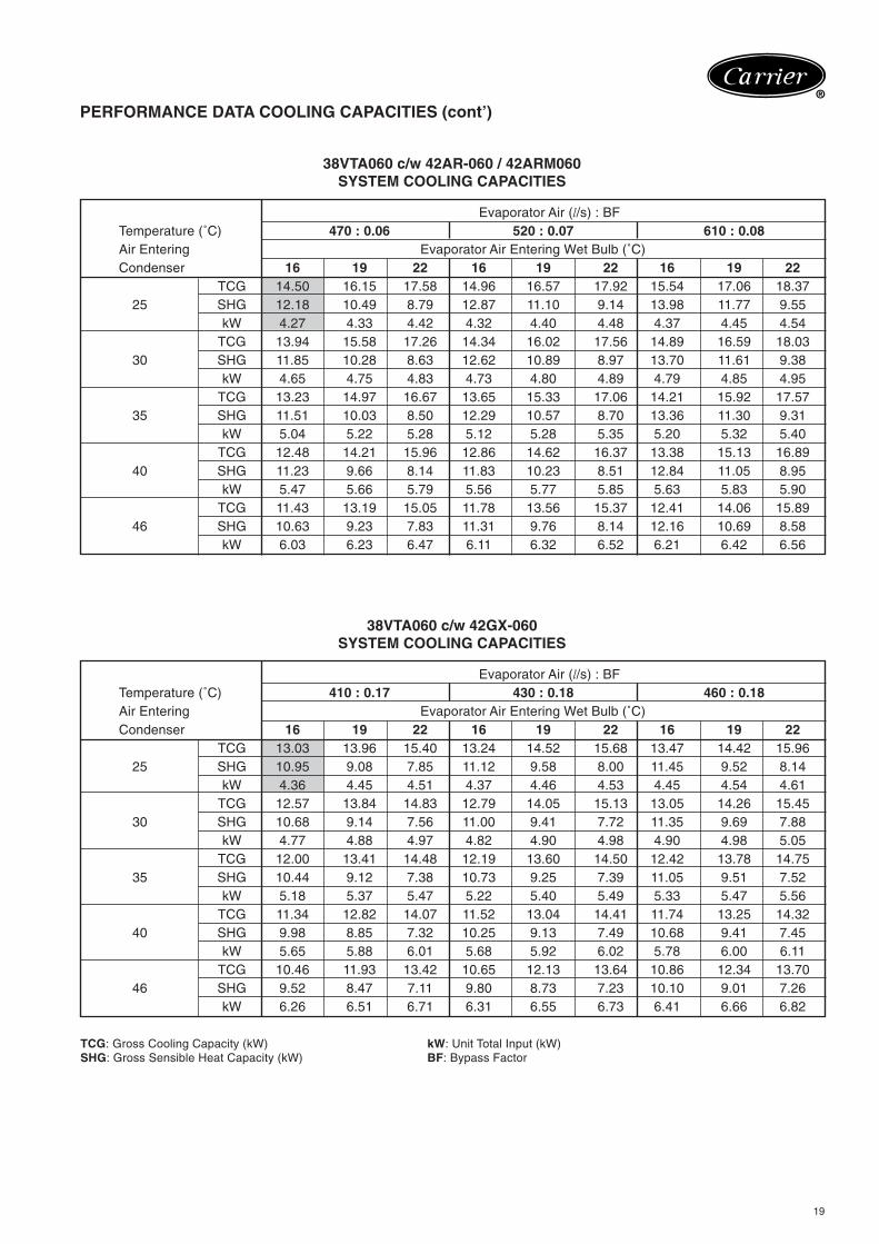
38VTA060 c/w 42AR-060 / 42ARM060SYSTEM COOLING CAPACITIES
Evaporator Air (l/s) : BFTemperature (˚C) 470 : 0.06 520 : 0.07 610 : 0.08Air Entering Evaporator Air Entering Wet Bulb (˚C)Condenser 16 19 22 16 19 22 16 19 22
TCG 14.50 16.15 17.58 14.96 16.57 17.92 15.54 17.06 18.3725 SHG 12.18 10.49 8.79 12.87 11.10 9.14 13.98 11.77 9.55
kW 4.27 4.33 4.42 4.32 4.40 4.48 4.37 4.45 4.54TCG 13.94 15.58 17.26 14.34 16.02 17.56 14.89 16.59 18.03
30 SHG 11.85 10.28 8.63 12.62 10.89 8.97 13.70 11.61 9.38kW 4.65 4.75 4.83 4.73 4.80 4.89 4.79 4.85 4.95
TCG 13.23 14.97 16.67 13.65 15.33 17.06 14.21 15.92 17.5735 SHG 11.51 10.03 8.50 12.29 10.57 8.70 13.36 11.30 9.31
kW 5.04 5.22 5.28 5.12 5.28 5.35 5.20 5.32 5.40TCG 12.48 14.21 15.96 12.86 14.62 16.37 13.38 15.13 16.89
40 SHG 11.23 9.66 8.14 11.83 10.23 8.51 12.84 11.05 8.95kW 5.47 5.66 5.79 5.56 5.77 5.85 5.63 5.83 5.90
TCG 11.43 13.19 15.05 11.78 13.56 15.37 12.41 14.06 15.8946 SHG 10.63 9.23 7.83 11.31 9.76 8.14 12.16 10.69 8.58
kW 6.03 6.23 6.47 6.11 6.32 6.52 6.21 6.42 6.56
38VTA060 c/w 42GX-060SYSTEM COOLING CAPACITIES
Evaporator Air (l/s) : BFTemperature (˚C) 410 : 0.17 430 : 0.18 460 : 0.18Air Entering Evaporator Air Entering Wet Bulb (˚C)Condenser 16 19 22 16 19 22 16 19 22
TCG 13.03 13.96 15.40 13.24 14.52 15.68 13.47 14.42 15.9625 SHG 10.95 9.08 7.85 11.12 9.58 8.00 11.45 9.52 8.14
kW 4.36 4.45 4.51 4.37 4.46 4.53 4.45 4.54 4.61TCG 12.57 13.84 14.83 12.79 14.05 15.13 13.05 14.26 15.45
30 SHG 10.68 9.14 7.56 11.00 9.41 7.72 11.35 9.69 7.88kW 4.77 4.88 4.97 4.82 4.90 4.98 4.90 4.98 5.05
TCG 12.00 13.41 14.48 12.19 13.60 14.50 12.42 13.78 14.7535 SHG 10.44 9.12 7.38 10.73 9.25 7.39 11.05 9.51 7.52
kW 5.18 5.37 5.47 5.22 5.40 5.49 5.33 5.47 5.56TCG 11.34 12.82 14.07 11.52 13.04 14.41 11.74 13.25 14.32
40 SHG 9.98 8.85 7.32 10.25 9.13 7.49 10.68 9.41 7.45kW 5.65 5.88 6.01 5.68 5.92 6.02 5.78 6.00 6.11
TCG 10.46 11.93 13.42 10.65 12.13 13.64 10.86 12.34 13.7046 SHG 9.52 8.47 7.11 9.80 8.73 7.23 10.10 9.01 7.26
kW 6.26 6.51 6.71 6.31 6.55 6.73 6.41 6.66 6.82
TCG: Gross Cooling Capacity (kW) kW: Unit Total Input (kW)SHG: Gross Sensible Heat Capacity (kW) BF: Bypass Factor
20
®
PERFORMANCE DATA COOLING CAPACITIES (cont’)
COMBINATION RATING NOTES:
1. Direct interpolation is permissible. Do not extrapolate.2. Capacities include indoor fan motor heat.3. SHG is based on 27.0˚C dB / 19.0˚C WB for air entering indoor coil. At any other temperature, correct the SHG reading from
the table of cooling capacities as follows:
BELOW 27.0˚C dB, SUBTRACT (Corr. Factor x l/s) from SHGABOVE 27.0˚C dB, ADD (Corr. Factor x l/s) to SHG
Correction Factor = 1.23 (1-BF) (dB - 27.0)
103
4. “INPUT” includes both outdoor and indoor unit.5. Capacities based on 7.5m long tubing with 1m level difference and applicable to outdoor unit voltage range of 342V to 440V.6. Operating limit: Entering air temperature to condenser should be in the range of 25.0˚C to 46.0˚C (75.0˚F to 115.0˚F).
Not recommended to operate outside this range.
NOT RECOMMENDED FOR SUSTAINED OPERATION IN THIS REGION
The above system capacity is rated to JIS at rated voltage.
21
®
AIR-COOLED CONDENSING UNIT PERFORMANCE RATING
Air Temperature Entering Condenser (˚C)
SST (˚C) 25 30 35 40 46
CAP 5.77 5.16 4.50 3.76 2.77
-1 SDT 35.82 40.04 44.12 47.12 52.36
kW 1.74 1.90 2.06 2.20 2.37
CAP 6.03 5.43 4.78 4.04 3.05
0 SDT 36.27 40.51 44.60 48.48 52.87
kW 1.76 1.93 2.09 2.24 2.40
CAP 7.20 6.60 5.94 5.20 4.23
4 SDT 38.20 42.49 46.63 50.54 55.03
kW 1.86 2.04 2.21 2.38 2.57
CAP 8.42 7.81 7.14 6.41 5.46
8 SDT 40.24 44.58 48.75 52.72 57.28
kW 1.95 2.15 2.34 2.52 2.73
CAP 9.07 8.45 7.78 7.05 6.10
10 SDT 41.32 45.70 45.70 53.89 58.46
kW 2.00 2.21 2.41 2.60 2.82
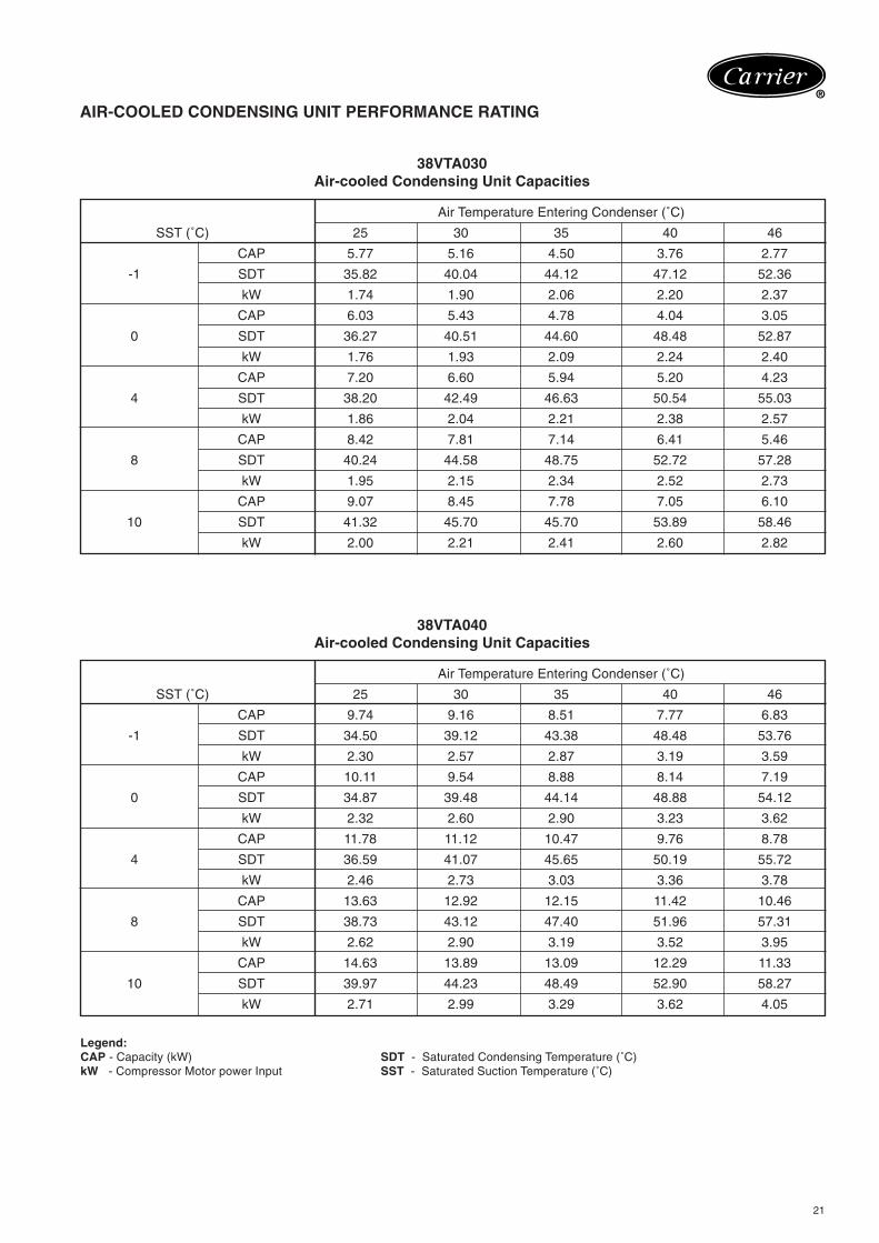
38VTA030Air-cooled Condensing Unit Capacities
38VTA040Air-cooled Condensing Unit Capacities
Legend:CAP - Capacity (kW) SDT - Saturated Condensing Temperature (˚C)kW - Compressor Motor power Input SST - Saturated Suction Temperature (˚C)
Air Temperature Entering Condenser (˚C)
SST (˚C) 25 30 35 40 46
CAP 9.74 9.16 8.51 7.77 6.83
-1 SDT 34.50 39.12 43.38 48.48 53.76
kW 2.30 2.57 2.87 3.19 3.59
CAP 10.11 9.54 8.88 8.14 7.19
0 SDT 34.87 39.48 44.14 48.88 54.12
kW 2.32 2.60 2.90 3.23 3.62
CAP 11.78 11.12 10.47 9.76 8.78
4 SDT 36.59 41.07 45.65 50.19 55.72
kW 2.46 2.73 3.03 3.36 3.78
CAP 13.63 12.92 12.15 11.42 10.46
8 SDT 38.73 43.12 47.40 51.96 57.31
kW 2.62 2.90 3.19 3.52 3.95
CAP 14.63 13.89 13.09 12.29 11.33
10 SDT 39.97 44.23 48.49 52.90 58.27
kW 2.71 2.99 3.29 3.62 4.05
22
®
AIR-COOLED CONDENSING UNIT PERFORMANCE RATING (cont’)
Air Temperature Entering Condenser (˚C)
SST (˚C) 25 30 35 40 46
CAP 11.81 11.03 10.13 9.12 7.77
-1 SDT 36.08 40.67 45.16 49.59 54.66
kW 2.97 3.30 3.66 4.05 4.56
CAP 12.28 11.49 10.60 9.57 8.23
0 SDT 36.48 41.07 45.56 49.98 55.07
kW 2.99 3.32 3.68 4.08 4.59
CAP 14.31 13.47 12.56 11.54 10.14
4 SDT 38.24 42.79 47.29 51.70 56.86
kW 3.11 3.44 3.81 4.22 4.76
CAP 16.59 15.60 14.62 13.58 12.17
8 SDT 40.46 44.71 49.17 53.56 58.70
kW 3.26 3.59 3.96 4.38 4.94
CAP 17.76 16.77 15.69 14.63 13.21
10 SDT 41.42 45.80 50.08 54.54 59.68
kW 3.33 3.67 4.43 4.47 5.04
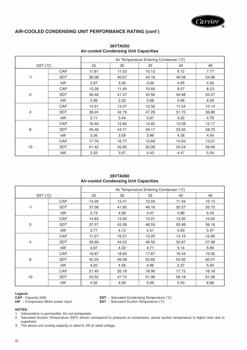
38VTA050Air-cooled Condensing Unit Capacities
38VTA060Air-cooled Condensing Unit Capacities
Legend:CAP - Capacity (kW) SDT - Saturated Condensing Temperature (˚C)kW - Compressor Motor power Input SST - Saturated Suction Temperature (˚C)
NOTES:1. Interpolation is permissible. Do not extrapolate.2. Saturated Suction Temperature (SST) shown correspond to pressure at compressor, actual suction temperature is higher than due to
superheat.3. The above unit cooling capacity is rated to JIS at rated voltage.
Air Temperature Entering Condenser (˚C)
SST (˚C) 25 30 35 40 46
CAP 14.26 13.41 12.50 11.49 10.14
-1 SDT 37.08 41.65 46.16 50.57 55.72
kW 3.73 4.08 4.47 4.89 5.43
CAP 14.83 13.93 13.01 12.00 10.65
0 SDT 37.57 42.09 46.59 50.99 56.16
kW 3.77 4.12 4.51 4.93 5.47
CAP 17.27 16.27 15.20 14.15 12.80
4 SDT 39.89 44.23 48.50 52.87 57.98
kW 3.97 4.33 4.71 5.14 5.69
CAP 19.97 18.83 17.67 16.43 15.02
8 SDT 42.25 46.58 50.83 54.92 60.01
kW 4.20 4.56 4.96 5.37 5.94
CAP 21.40 20.18 18.96 17.72 16.18
10 SDT 43.52 47.74 51.98 56.18 61.08
kW 4.32 4.69 5.09 5.53 6.08
23
®
GUIDE SPECIFICATIONS
Furnish and install air-cooled condensing unit in the locationand manner shown in the IOM. The unit shall be properlyassembled and tested at the factory. It shall be designed foruse with refrigerant R-22 and shall be suitable for use with230V-1Ø-50Hz electrical supply for 38VTA030 and 400V-3Ø-50Hz electrical supply for 38VTA040, 050 & 060.
The condensing unit shall have capacity of ……. watts ormore, with the temperature of air entering condenser at ……..˚C and a saturated suction temperature of ……….. ˚C.
The condenser coil shall be of non-ferrous construction suchthat it has aluminium plate fins with “Lanced Sine Wave”pattern mechanically bonded to seamless copper tubing. Theunit shall be furnished with direct driven, propeller type fanarrangement for horizontal discharge. The unit shall have afan guard and offers quick access and easy maintenance.The condenser fan motor shall have inherent protection andshall be of the permanently lubricated type.
The compressor shall be the fully-hermetic rotary type(38VTA030) and scroll type (38VTA040, 050 & 060). Thecontrols shall be factory wired and located in a separateenclosure.
Casing shall make unit fully weatherproofed for outdoorinstallation. The panels shall be manufactured from heavygauge galvanized steel, phosphatised and finished in bakedenamel powder paint.
The dimension of the entire assembly for 38VTA shall not bemore than 650mm high, 825mm length and 340mm width,and for 38VTA040~060 shall not be more than 945mm high,1130mm length and 432mm width.
24
®
Catalogue # 38VTA-D04-1PDCopyright © 2004 Carrier - A United Technologies Company
04 2004
38 VTA NEW
Carrier International Sdn. Bhd. (3385-T)Lot 4, Jalan P/6, 43650 Bandar Baru Bangi,
Selangor Darul Ehsan, Malaysia.Tel: 603-8925 8001Fax: 603-8925 3578
CarrierInternationalSdn. Bhd.Malaysia (3385-T)
®
Manufacturer reserves the right to discontinue,or change at any time, specifications or designswithout notice and without incurring obligation.