Embed Size (px)
Citation preview

PRODUCT COMPONENT
SUBMITTALS
GHP Systems, Inc. 1000 32nd Avenue Brookings, SD 57006 www.ghpsystems.com
(605) 697-7867 tel (605) 697- 9118 fax 888-447-7757 toll-free
• Pipe & Fittings • Butterfly Valves • Brass Ball Valves • Balancing Valves • P/T Test Plugs • Pressure Gauges • Temperature Indicators
• Link-Seals • Sump Pump • Electrical Receptacles • Floodlights • Electrical Switch • Blower
Bulletin: PP 655 April 2002 Supercedes all previous publications Page 1 of 1 © 2002 Chevron Phillips Chemical Company LP
www.performancepipe.com
DRISCOPLEX® 5300 CLIMATE GUARD®
PIPE AND FITTINGS Scope: This Product Submittal is for DriscoPlex® 5300 Climate Guard® pipe and fittings for geothermal (ground source heat pump) applications. Reference Documents: DriscoPlex® 5300 Climate Guard® pipe is manufactured in accordance with ASTM D-3035. DriscoPlex® 5300 Climate Guard fittings are manufactured in accordance with ASTM D-2683 for socket fusion fittings, ASTM D-3261 for butt fusion fittings, ASTM F-1055 for electrofusion fittings and ASTM F-1924, Section 3.1.6.1 for Mechanical Fittings. Materials: DriscoPlex® 5300 Climate Guard® polyethylene pipe and heat fused materials are manufactured from high density polyethylene material meeting ASTM D-3350 cell classification 345464C. The material has a 1600 psi Hydrostatic Design Basis at 73°F per ASTM D-2837 and is listed in the manufacturers name in PPI TR4 as a PE3408 compound. Certification: Performance Pipe certifies that DriscoPlex® 5300 Climate Guard® pipe and fittings meet the specifications and requirements identified herein. Limited Warranty Summary: Performance Pipe warrants, subject to specific conditions, Climate Guard® 5300 Series pipe and fusion fittings for a period of 50 years against rust, rot, electrolytic corrosion and defects in workmanship and materials. This warranty is valid when pipe, tubing and/or fittings are utilized and installed in a closed loop geothermal heat pump system in accordance with accepted and approved industry guidelines and practices. (See Full Limited Warranty for complete terms, conditions and disclaimers).
Project Name: Project Location: Contractor:
PRODUCT SUBMITTAL
PERFORMANCE PIPE, a division of Chevron Phillips Chemical Company LP PO Box 269006 / Plano, TX 75026-9006
Phone: 1-800-527-0662 / Fax: 972-599-7348 www.performancepipe.com

DRISCOPLEX® 5300 Series Climate Guard® ®
Polyethylene Pipe and Fusion Fittings Polyethylene Pipe and Fusion Fittings Limited Warranty Limited Warranty
5300 Series Products:5300 Series Products:
Performance Pipe warrants DriscoPlex® 5300 Series Climate Guard® pipe and fusion fittings for a period of 50 years against defects in workmanship and materials. This warranty is valid when pipe and/or fittings are utilized and installed in a closed loop geothermal heat pump system in accordance with accepted and approved industry guidelines and practices. This warranty applies only to Performance Pipe DriscoPlex® 5300 Series Climate Guard® pipe and fusion fittings. It does not apply to any fusion joining process or any other method or device used to join the pipe or fusion fitting performed by any other party. It does not apply to the design or installation of the system or any other component of the system.
Subject to the price adjustments described below, Performance Pipe will replace, with a like
quantity of new products, any DriscoPlex® 5300 Series Climate Guard® pipe or fusion fittings that were installed and utilized as described above and that subsequently fail within fifty (50) years from the date of purchase due to a defect in workmanship or materials. For warranty claims occurring within one year after the date of purchase, the defective product(s) shall be replaced free of product and freight charges. For warranty claims occurring during the second (2nd) through eleventh (11th) years after the date of purchase, the replacement product cost and freight expense borne by Performance Pipe shall be calculated by reducing the then current price by eight percent (8%) per year. For warranty claims occurring during the twelfth (12th) through the fiftieth (50th) years after the date of purchase, the replacement product cost and freight expense borne by Performance Pipe shall be calculated by reducing the then current price by eighty percent (80%) plus one half percent (0.5%) per year for each year after the 11th year.
SUBJECT TO ANY EXPRESS WARRANTIES CONTAINED IN PERFORMANCE PIPE’S SALES ORDER APPLICABLE TO THE PRODUCT(S) IN QUESTION, THIS LIMITED WARRANTY IS IN LIEU OF ALL OTHER WARRANTIES, WHETHER WRITTEN, ORAL, EXPRESS OR IMPLIED, AND PERFORMANCE PIPE DISCLAIMS ANY EXPRESS OR IMPLIED WARRANTIES OF MERCHANTABILITY AND FITNESS FOR A PARTICULAR PURPOSE. PERFORMANCE PIPE SHALL NOT BE LIABLE FOR SPECIAL, INDIRECT, INCIDENTAL OR CONSEQUENTIAL DAMAGES RELATING TO DEFECTS OF PERFORMANCE PIPE DRISCOPLEX® 5300 SERIES CLIMATE GUARD® PIPE AND FUSION FITTINGS, WHETHER USED SINGULARLY OR IN COMBINATION WITH OTHER PRODUCTS OR MATERIALS. Some states do not allow this exclusion, so it may not apply to you. This limited warranty gives the purchaser specific legal rights and there may be other rights, which vary from state to state.
Bulletin: PP 653 August 2005 Supercedes all previous publications Page 1 of 1 © 2002-2005 Chevron Phillips Chemical Company LP
DRISCOPLEX® 5300 SERIES CLIMATE GUARD® SYSTEMS
DRISCOPLEX® Series 5300 Climate Guard®
HDPE Pipe and Fitting System forClosed-Loop Ground-Source Heat Pump Applications
Bulletin: PP 650

Performance Pipe
PERFORMANCE PIPE is the functional successor to the operations of Plexco1 and Driscopipe2 . OnJuly 1, 2000, Chevron Chemical Company and Phillips Chemical Company were joined to form ChevronPhillips Chemical Company LP. Performance Pipe, a division of Chevron Phillips Chemical CompanyLP, succeeds Plexco and Driscopipe as North America's largest producer of polyethylene pipingproducts for geothermal, industrial, municipal, mining, oilfield, gas and utility applications.
Performance Pipe offers more than forty years of polyethylene pipe manufacturing experience, ninemanufacturing facilities ISO certified in eight states.
The unmatched quality and performance of Performance Pipe polyethylene piping products is enhancedand strengthened with over four decades of quality polyolefin plastic resin production from ChevronPhillips Chemical Company LP.
DRISCOPLEX® 5300 Series Climate Guard® Pipe and Fitting System
DriscoPlex® 5300 Series Climate Guard® high-density polyethylene pipe and fittings are the qualitypiping system for closed-loop, earth-coupled heat pump applications. DriscoPlex® 5300 Series ClimateGuard® pipe and fittings are the system of choice for residential, commercial, institutional and industrialinstallations. Performance Pipe offers a complete system of DriscoPlex® 5300 pressure-rated pipe andfittings that meet or exceed applicable IGSHPA andASTM specifications and requirements.
DRISCOPLEX® 5300 Climate Guard®
Systems - The Key to PerformanceEconomical - Easy to join, lightweight and flexibleto help reduce construction and installation costs.
Tough and Durable - Excellent impact andabrasion resistance. Pressure ratings based onlong-term tests. Exceptional resistance to slowcrack growth and environmental stress cracking.
www.performancepipe.com
NOTICE - This publication is intended for use as a guide to support the designer of piping systems. It is not intendedto be used as installation instructions, and should not be used in place of the advice of a professional engineer. Itdoes not constitute a guarantee or warranty for piping installations. Performance Pipe has made every reasonableeffort to ensure the accuracy of this publication, but it may not provide all necessary information, particularly withrespect to special or unusual applications. This publication may be changed from time to time without notice. ContactPerformance Pipe to determine if you have the most current edition.
1 Formerly - Plexco, a Division of Chevron Chemical Company2 Formerly - Phillips Driscopipe, A Division of Phillips Petroleum Company
DRISCOPLEX® 5300 Series Climate Guard®
HDPE Pipe and Fitting System forClosed-Loop Ground-Source Heat Pump Applications
Bulletin: PP 650 January 2007 Supersedes all previous publicationsPage 2 of 8 © 2002-2007 Chevron Phillips Chemical Company LP

Ductile and Flexible - Flexible DriscoPlex® 5300 Climate Guard® Series pipe follows the "lay ofthe land" to ease trench and down hole installation.
Resistant to Chemicals and Corrosion - Excellent resistance to most chemical compounds and aggressive soils.
Thermally Conductive - DriscoPlex® 5300 Climate Guard® pipe offers high strength PE 3408 to minimize pipe wall thickness and maximize heat transfer.
Leak-Tight Joining - Long, continuous coils or straight lengths reduce joining requirements. Properly made heat fusion joints are as strong as the pipe itself and do not leak.
Excellent Hydraulics - DriscoPlex® 5300 Climate Guard® pipe offers high volume flows with lowflow resistance. The hydraulically smooth, non-wetting surface provides excellent flow properties. A Hazen-Williams C-factor of l50-155 is typically used to estimate flow resistance.DriscoPlex® 5300 Climate Guard® pipe does not rust, rot, corrode, tuberculate or support biological growth.
Sequential Footage Markings on coils to assist with proper depth setting in borehole installations.
DRISCOPLEX® 5300 Climate Guard® Pipe and Fitting ProductsPipe
· PE 3408 DR 11- 3/4" IPS, 1" IPS, 1-1/4" IPS, 1-1/2" IPS, 2" IPS, 3" IPS and 4" IPS standard.
· PE 3408 DR 15.5 - 3" IPS, 4" IPS, 6" IPS and 8" IPS standard.
· Other sizes through 54" IPS, other DR's, and Schedule 40 available upon request.
· DriscoPlex® 5300 Climate Guard® Unicoil™ proprietary twin-coil with patented Polywing™ u-bendfor down hole or horizontal loop applications - 3/4" IPS, 1" IPS and 1-1/4" IPS
Fittings and ValvesDriscoPlex® 5300 Climate Guard® molded fittings for butt fusion through 8" IPS and for socket fusion through 4" IPS.
· Materials and StandardsDriscoPlex® 5300 Climate Guard® pipe and molded fittings are manufactured from high-density,high molecular weight PE 3408 polyethylene compound that meets or exceeds ASTM D 3350 cell classification 345464C, and is listed by the Plastic Pipe Institute in PPI TR-4 with HDB ratings of 1600 psi (11.04 MPa) at 73°F (23°C) and 800 psi (5.52 MPa) at 140°F (60°C).
DriscoPlex® 5300 Climate Guard® pipe is manufactured in accordance with ASTM D 3035. Molded fittings are manufactured in accordance with ASTM D 3261 (butt outlet) and ASTM D 2683 (socket outlet).
www.performancepipe.com
Bulletin: PP 650 January 2007 Supersedes all previous publicationsPage 3 of 8 © 2002-2007 Chevron Phillips Chemical Company LP
Secure JoiningDriscoPlex® 5300 Climate Guard® pipe and fittings are quickly joined by socket, butt or saddle heatfusion, electrofusion, or mechanical fittings. Climate Guard® 5300 mechanical connection fittings areavailable for joining to other materials or to itself. Suitable electrofusion fittings may also be used. Heatfusion joining procedures are available upon request.
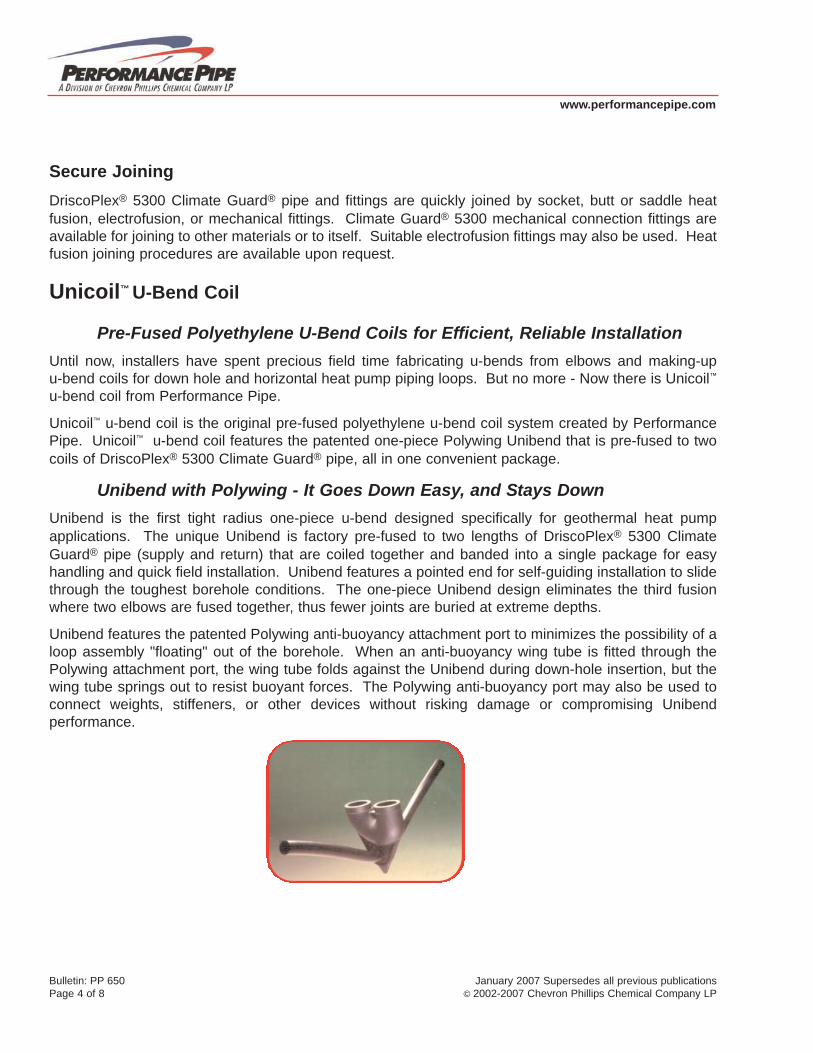
Unicoil™ U-Bend Coil
Pre-Fused Polyethylene U-Bend Coils for Efficient, Reliable InstallationUntil now, installers have spent precious field time fabricating u-bends from elbows and making-upu-bend coils for down hole and horizontal heat pump piping loops. But no more - Now there is Unicoil™u-bend coil from Performance Pipe.
Unicoil™ u-bend coil is the original pre-fused polyethylene u-bend coil system created by PerformancePipe. Unicoil™ u-bend coil features the patented one-piece Polywing Unibend that is pre-fused to twocoils of DriscoPlex® 5300 Climate Guard® pipe, all in one convenient package.
Unibend with Polywing - It Goes Down Easy, and Stays DownUnibend is the first tight radius one-piece u-bend designed specifically for geothermal heat pumpapplications. The unique Unibend is factory pre-fused to two lengths of DriscoPlex® 5300 ClimateGuard® pipe (supply and return) that are coiled together and banded into a single package for easyhandling and quick field installation. Unibend features a pointed end for self-guiding installation to slidethrough the toughest borehole conditions. The one-piece Unibend design eliminates the third fusionwhere two elbows are fused together, thus fewer joints are buried at extreme depths.
Unibend features the patented Polywing anti-buoyancy attachment port to minimizes the possibility of aloop assembly "floating" out of the borehole. When an anti-buoyancy wing tube is fitted through thePolywing attachment port, the wing tube folds against the Unibend during down-hole insertion, but thewing tube springs out to resist buoyant forces. The Polywing anti-buoyancy port may also be used toconnect weights, stiffeners, or other devices without risking damage or compromising Unibendperformance.
www.performancepipe.com
Bulletin: PP 650 January 2007 Supersedes all previous publicationsPage 4 of 8 © 2002-2007 Chevron Phillips Chemical Company LP

Configurations
DriscoPlex® 5300 Climate Guard® Unicoil™ piping systems are available in three pipe sizes and twopressure ratings.
• Pipe sizes: 3/4" IPS, 1" IPS or 1-1/4" IPS
• Working pressure ratings: SDR 11 160 psi water at 73°F (standard) or SDR 9 200 psi water at 73°F (special order) for deep installations or high static pressures.
• Outside width across Unibend†: 3/4" IPS & 1" IPS 3 1/4" wide1-1/4" IPS 4" wide
† This dimension is the approximate outside width across the Unibend at the end of the Unicoil™ u-bendcoil including the fusion beads. When used in downhole applications, appropriate clearance betweenthe borehole and the outside width of the Unibend is required to allow downhole passage.
DriscoPlex® 5300 Climate Guard® Unicoil™ geothermal piping systems sets the standard for reliability,cost-efficiency and ease of installation in the ground source heat pump industry.
General Guidelines for Closed-Loop Ground-Source Heat Pump Applications· Verify that the total system pressure, operating plus surge, does not exceed the pressure rating
of the lowest rated component in the system.
· Carefully inspect the pipe to detect any damage that may have occurred during shipping or handling.
· Conduct hydrostatic leak testing in accordance with Performance Pipe procedures. Do not testpiping with pressurized air.
· Install DriscoPlex® 5300 Climate Guard® piping products in accordance with accepted standardsfor water-source heat pump applications and ASTM D 2774 Underground Installation of Thermoplastic Pressure Piping.
· When laid in a trench, ensure that the trench bottom is smooth and free from sharp or angular objects. Embedment soils must be free from refuse, organic material, cobbles, boulders, large rocks or stones, and frozen clods. Blocking must be not be used to change pipe grade or to intermittently support pipe across excavated sections.
· When installed down-hole, such as in a vertical loop, be sure any ballast used to facilitate down-hole insertion does not impinge, gouge or cut into the pipe.
www.performancepipe.com
Bulletin: PP 650 January 2007 Supersedes all previous publicationsPage 5 of 8 © 2002-2007 Chevron Phillips Chemical Company LP

Technical InformationHeat Transfer
Heat transfer properties of various materials can be expressed by a "K-Value". A higher K-Value reflectsgreater heat transfer properties.
www.performancepipe.com
Material K-Value, BTU-h/ft-°F
DriscoPlex™ 5300 Climate Guard® PE 3408 0.225
PVC 0.087
Table 1 Approximate Water Volume for 100 Feet of Pipe†
Table 2 Climate Guard® 5300 Pressure Rating (psi) vs. Temperature (ºF)‡
Bulletin: PP 650 January 2007 Supersedes all previous publicationsPage 6 of 8 © 2002-2007 Chevron Phillips Chemical Company LP
Nominal Pipe Size Gallons Nominal Pipe Size Gallons 3/4” IPS DR 11 2.93 3” IPS DR 11 32.57 1” IPS DR 11 4.60 4” IPS DR 11 53.84
1-1/4” IPS DR 11 7.33 6” IPS DR 15.5 133.47 1-1/2” IPS DR 11 9.60 8” IPS DR 15.5 226.17
2” IPS DR 11 15.00 * Approximate volume of water in U.S. gallons at 73ºF for ASTM D 3035 nominal outside diameter and average wall thickness for pipe.
Temp, ºF DR 15.5 SDR 11 SDR 9** 73 110 160 200 80 104 151 189 90 95 138 173
100 87 126 157 110 78 114 142 120 70 102 128 130 63 91 114 140 55 80 100
* PE 3408 pressure ratings for water. PE 3408 HDB = 1600 psi at 73ºF and 800 psi at 140ºF. Intermediate temperature LTHS interpolated in accordance with PPI TN-18. ** Optional SDR 9 for Unicoil™.

www.performancepipe.com
3/4”
IPS
DR
11
1” IP
S D
R 1
1 1-
1/4”
IPS
DR
11
1-1/
2” IP
S D
R 1
1 2”
IPS
DR
11
3” IP
S D
R 1
1 4”
IPS
DR
11
6” IP
S D
R 1
5.5
8” IP
S D
R 1
5.5
GP
M
psi
fps
psi
fps
psi
fps
psi
fps
psi
fps
psi
fps
psi
fps
psi
fps
psi
fps
2 0.
34
1.14
0.
11
0.73
0.
04
0.46
0.
02
0.35
0.
01
0.22
3 0.
73
1.71
0.
24
1.09
0.
08
0.68
0.
04
0.52
0.
01
0.33
4 1.
24
2.27
0.
41
1.45
0.
13
0.91
0.
07
0.69
0.
02
0.44
5 1.
87
2.84
0.
63
1.81
0.
20
1.14
0.
10
0.87
0.
04
0.56
0.
01
0.26
6 2.
62
3.41
0.
88
2.18
0.
28
1.37
0.
15
1.04
0.
05
0.67
0.
01
0.31
7 3.
48
3.98
1.
17
2.54
0.
38
1.59
0.
19
1.22
0.
07
0.78
0.
01
0.36
8 4.
46
4.55
1.
49
2.90
0.
48
1.82
0.
25
1.39
0.
08
0.89
0.
01
0.41
9 5.
54
5.12
1.
85
3.26
0.
60
2.05
0.
31
1.56
0.
10
1.00
0.
02
0.46
10
6.74
5.
69
2.25
3.
63
0.73
2.
28
0.38
1.
74
0.13
1.
11
0.02
0.
51
0.01
0.
31
12
3.16
4.
35
1.02
2.
73
0.53
2.
08
0.18
1.
33
0.03
0.
61
0.01
0.
37
15
4.77
5.
44
1.54
3.
41
0.80
2.
60
0.27
1.
67
0.04
0.
77
0.01
0.
46
18
6.69
6.
53
2.15
4.
10
1.12
3.
13
0.38
2.
00
0.06
0.
92
0.02
0.
56
21
2.86
4.
78
1.48
3.
65
0.50
2.
33
0.08
1.
07
0.02
0.
65
24
3.66
5.
46
1.90
4.
17
0.64
2.
67
0.10
1.
23
0.03
0.
74
27
4.56
6.
14
2.36
4.
69
0.80
3.
00
0.12
1.
38
0.04
0.
84
30
5.54
6.
83
2.87
5.
21
0.97
3.
33
0.15
1.
54
0.04
0.
93
35
7.37
7.
96
3.82
6.
08
1.29
3.
89
0.20
1.
79
0.06
1.
08
0.01
0.
44
40
4.89
6.
95
1.65
4.
45
0.25
2.
05
0.07
1.
24
0.01
0.
50
45
6.08
7.
81
2.05
5.
00
0.31
2.
30
0.09
1.
39
0.01
0.
56
50
7.39
8.
68
2.49
5.
56
0.38
2.
56
0.11
1.
55
0.01
0.
62
55
2.97
6.
11
0.45
2.
81
0.13
1.
70
0.01
0.
69
60
3.49
6.
67
0.53
3.
07
0.16
1.
86
0.02
0.
75
70
4.65
7.
78
0.70
3.
58
0.21
2.
17
0.02
0.
87
0.01
0.
52
80
5.95
8.
89
0.90
4.
09
0.27
2.
48
0.03
1.
00
0.01
0.
59
90
7.40
10
.00
1.12
4.
61
0.33
2.
79
0.04
1.
12
0.01
0.
66
100
1.36
5.
12
0.40
3.
10
0.04
1.
25
0.01
0.
84
110
1.63
5.
63
0.48
3.
41
0.05
1.
37
0.01
0.
81
120
1.91
6.
14
0.56
3.
72
0.06
1.
50
0.02
0.
88
130
2.21
6.
65
0.65
4.
02
0.07
1.
82
0.02
0.
96
†U.S
. gal
lons
of w
ater
. A
STM
D 3
035
nom
inal
out
side
dia
met
er &
ave
rage
wal
l thi
ckne
ss.
Pre
ssur
e dr
op e
stim
ated
usi
ng H
azen
-Willi
ams
C =
150
for w
ater
at 6
0°F.
Tabl
e 3
Estim
ated
Flo
w P
rope
rtie
s fo
r 10
0 Fe
et o
f Pip
e - G
PM, P
ress
ure
Dro
p (p
si),
Velo
city
(fps
)†
Bulletin: PP 650 January 2007 Supersedes all previous publicationsPage 7 of 8 © 2002-2007 Chevron Phillips Chemical Company LP

CONTACT INFORMATION:
PERFORMANCE PIPE, a division of Chevron Phillips Chemical CompanyLPPO Box 269006Plano, TX 75026-9006
To secure product information or technical assistance:
Phone: 800-527-0662Fax: 972-599-7348www.performancepipe.com
www.performancepipe.com
PERFORMANCE PIPEProduct Literature
Technical Notes & Bulletins*:
PP 102-DS DRISCOPLEX® 5300 Series Climate Guard® Geothermal Piping System Data Sheet
PP 652 Model Specifications for DRISCOPLEX® 5300 Climate Guard®
Systems
Bulletin: PP 650 January 2007 Supercedes all previous publicationsPage 8 of 8 © 2002-2007 Chevron Phillips Chemical Company LP
Bloomfield, IABrownwood, TXFairfield, IAHagerstown, MDKnoxville, TNPlano TXPryor, OKReno, NVStartex, SCWilliamstown, KY
FFBF
WT
ST
HG
PR
BW
RN
KV
Pipe
FittingsGeneral Office
Bloomfield, IABrownwood, TXFairfield, IAHagerstown, MDKnoxville, TNPlano TXPryor, OKReno, NVStartex, SCWilliamstown, KY
FFBF
WT
ST
HG
PR
BW
RN
KV
Pipe
FittingsGeneral Office
PERFORMANCE PIPE PLANTS
Strategically Located PlantsTo Better Serve Your Needs!
www.performancepipe.com Model Specifications DRISCOPLEX® 5300 Series Climate Guard® Systems for Geothermal Applications
Scope: This specification designates requirements for geothermal (ground source
heat pump) pipe and fittings. Material: All pipe and heat fused materials shall be manufactured from high density,
extra-high molecular weight PE 3408 material. The material shall maintain a 1600 psi Hydrostatic Design Basis at 73.4 degrees F per ASTM D-2837, and shall be listed in PPI TR4 as a PE3408 piping formulation. The material shall have a cell classification of 345464C as specified in ASTM D-3350.
Pipe: The extruded pipe shall conform to the specifications and requirements of
ASTM D-3035. Clean rework material from the manufacturer’s own production may be used provided the pipe or fittings meet all requirements of this specification. Recycled and reclaimed materials from outside the manufacturer’s plant shall not be used. Pipe used for vertical bore applications shall include a factory-fused, single, piece, injection molded U-bend Polywing fitting. The approved pipe product is DRISCOPLEX® 5300 Series Climate Guard® Pipe from Performance Pipe.
Fittings: Molded fittings shall be manufactured to the specifications and requirements
of ASTM D-2683 for socket fittings, ASTM D-3261 for butt fittings, ASTM F-1055 for electrofusion fittings and ASTM F-1924 Section 3.1.6.1 for Mechanical fittings. All fittings shall be rated for pressure service equivalent to SDR 11 PE 3408 pipe. The material used in fitting manufacture shall be the same approved base resin material as the connecting pipe.
The approved fittings are DRISCOPLEX® 5300 Series Climate Guard® Systems from Performance Pipe.
Joints: Approved joining methods are heat fusion, electrofusion, flanging, transition fittings and approved mechanical stab fittings. Persons performing heat fusion shall be qualified in accordance with the manufacturer’s recommended fusion joining procedures. Electrofusion and mechanical joints shall be made in accordance with the fitting manufacturer’s instructions.
NOTICE. This publication is for informational purposes and is intended for use as a reference guide. It should not be used in place of the advice of a professional engineer. This publication does not contain or confer any warranty or guarantee of any kind. Performance Pipe has made every reasonable effort towards the accuracy of the information contained in this publication, but it may not provide all necessary information, particularly with respect to special or unusual applications. This publication may be changed from time to time without notice. Contact Performance Pipe to ensure that you have the most current edition.
Bulletin: PP 652 March 2006 Supercedes all previous publications Page 1 of 2 © 2002-2006 Chevron Phillips Chemical Company LP
Bulletin: PP 652 March 2006 Supercedes all previous publications Page 2 of 2 © 2002-2006 Chevron Phillips Chemical Company LP
Manufacturer: The pipe and fittings manufacturer shall have in place a functional quality assurance program shall and be ISO (the International Organization for Standardization) Certified.
The approved manufacturer for pipe and fittings is Performance Pipe
Marking: Each pipe shall be durably marked with the manufacturer’s name, nominal
size, pressure rating, ASTM standard, material designation or cell classification number and date and location of manufacture. Coils shall be marked with footage marks at intervals no greater than two feet. Each fitting shall be identified with the manufacturer’s name, nominal size, ASTM standard and lot number.
Installation: Construction and installation shall be in compliance with IGSHPA Standards
(as amended from time to time) and all applicable local, state and federal regulations. The Contractor shall observe all appropriate safety requirements in accordance with local, state and federal codes and regulations.
Hydrotesting: The completed system shall be hydrostatically tested at a pressure not
greater than 150% of the pipe pressure rating in accordance with Performance Pipe hydrostatic leak testing procedures. Testing with compressed air or a compressed gas is prohibited.
PERFORMANCE PIPE, a division of Chevron Phillips Chemical Company LP PO Box 269006 Plano, TX 75026-9006 Phone: 1-800-527-0662 Fax: 972-599-7348 Web: www.performancepipe.com
For more information and technicalassistance contact:
Performance Pipe, a division ofChevron Phillips Chemical Company LPP.O. Box 269006Plano, TX 75026-9006800.527.0662
haht.product_family: Pipe, haht.content_type: TDS, cpchem.advancedSearch.section: =strFinalString%>
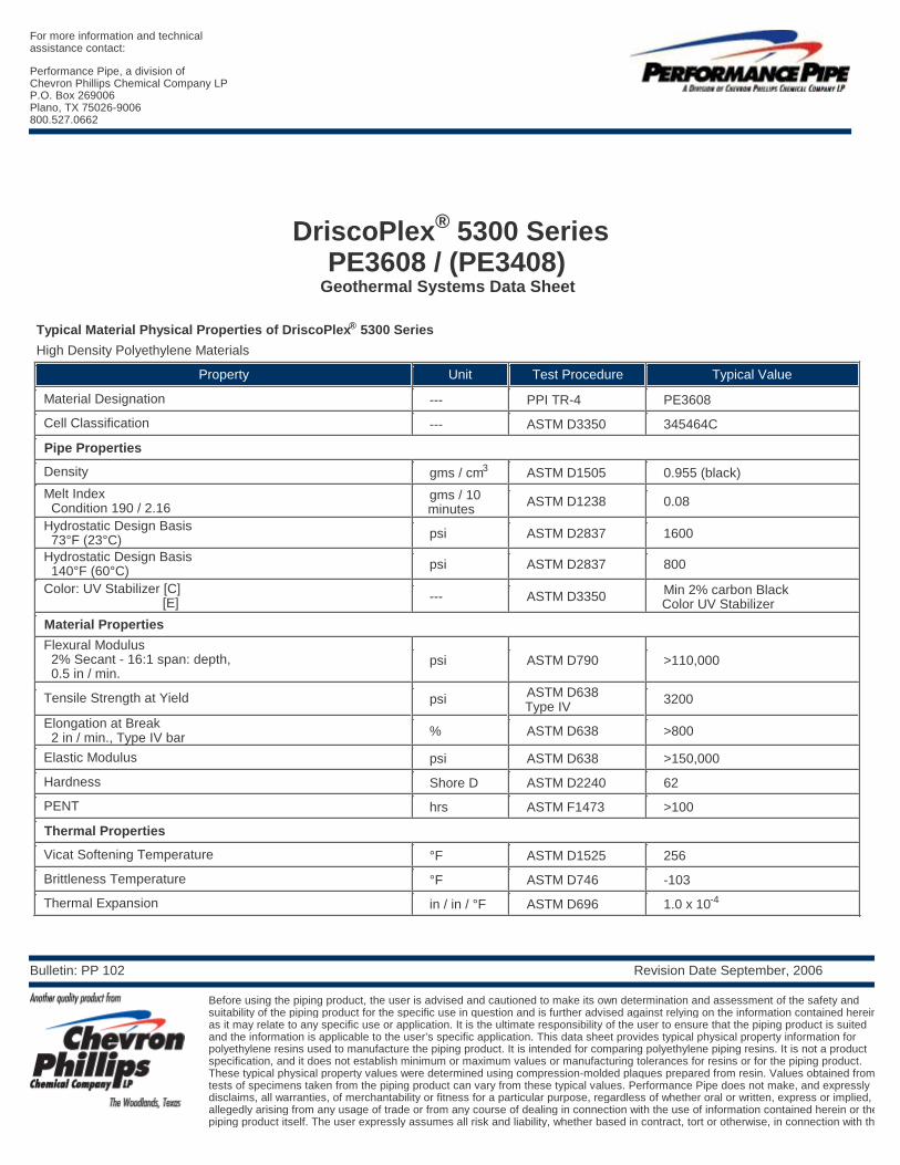
®DriscoPlex 5300 SeriesPE3608 / (PE3408)
Geothermal Systems Data Sheet
®Typical Material Physical Properties of DriscoPlex 5300 Series
High Density Polyethylene Materials
Property Unit Test Procedure Typical Value
Material Designation --- PPI TR-4 PE3608
Cell Classification --- ASTM D3350 345464C
Pipe Properties3 Density gms / cm ASTM D1505 0.955 (black)
Melt Index gms / 10 ASTM D1238 0.08 Condition 190 / 2.16 minutes Hydrostatic Design Basis psi ASTM D2837 1600 73°F (23°C) Hydrostatic Design Basis psi ASTM D2837 800 140°F (60°C) Color: UV Stabilizer [C] Min 2% carbon Black--- ASTM D3350 [E] Color UV Stabilizer
Material Properties
Flexural Modulus 2% Secant - 16:1 span: depth, psi ASTM D790 >110,000 0.5 in / min.
ASTM D638 Tensile Strength at Yield psi 3200 Type IV
Elongation at Break% ASTM D638 >800 2 in / min., Type IV bar
Elastic Modulus psi ASTM D638 >150,000
Hardness Shore D ASTM D2240 62
PENT hrs ASTM F1473 >100
Thermal Properties
Vicat Softening Temperature °F ASTM D1525 256
Brittleness Temperature °F ASTM D746 -103-4 Thermal Expansion in / in / °F ASTM D696 1.0 x 10
Bulletin: PP 102 Revision Date September, 2006
Before using the piping product, the user is advised and cautioned to make its own determination and assessment of the safety and suitability of the piping product for the specific use in question and is further advised against relying on the information contained herein as it may relate to any specific use or application. It is the ultimate responsibility of the user to ensure that the piping product is suited and the information is applicable to the user’s specific application. This data sheet provides typical physical property information for polyethylene resins used to manufacture the piping product. It is intended for comparing polyethylene piping resins. It is not a product specification, and it does not establish minimum or maximum values or manufacturing tolerances for resins or for the piping product. These typical physical property values were determined using compression-molded plaques prepared from resin. Values obtained from tests of specimens taken from the piping product can vary from these typical values. Performance Pipe does not make, and expressly disclaims, all warranties, of merchantability or fitness for a particular purpose, regardless of whether oral or written, express or implied, orallegedly arising from any usage of trade or from any course of dealing in connection with the use of information contained herein or the piping product itself. The user expressly assumes all risk and liability, whether based in contract, tort or otherwise, in connection with the

For more information and technicalassistance contact:
Performance Pipe, a division ofChevron Phillips Chemical Company LPP.O. Box 269006Plano, TX 75026-9006800.527.0662
Members Of:
NOTICE: This data sheet provides tpical physical property information for polyethylene resins used to manufacture PERFORMANCE PIPE polyethylene piping products. It is intended for comparing polyethylene piping resins. It is not a product specification, and it does not establish minimum or maximum values or manufacturing tolerances for resins or for piping products. Some of these typical physical property values were determined using compression molded plaques. Values obtained from tests of specimens taken from piping product can vary from these typical values. Performance Pipe has made every reasonable effort to ensure the accuracy of this data sheet, but this data sheet may not provide all necessary information, particularly with respect tospecial or unusual applications. The data sheet may be changed from time to time without notice. Contact Performance Pipe to determine if you have the most recent edition.
Bulletin: PP 102 Revision Date September, 2006
Before using the piping product, the user is advised and cautioned to make its own determination and assessment of the safety and suitability of the piping product for the specific use in question and is further advised against relying on the information contained herein as it may relate to any specific use or application. It is the ultimate responsibility of the user to ensure that the piping product is suited and the information is applicable to the user’s specific application. This data sheet provides typical physical property information for polyethylene resins used to manufacture the piping product. It is intended for comparing polyethylene piping resins. It is not a product specification, and it does not establish minimum or maximum values or manufacturing tolerances for resins or for the piping product. These typical physical property values were determined using compression-molded plaques prepared from resin. Values obtained from tests of specimens taken from the piping product can vary from these typical values. Performance Pipe does not make, and expressly disclaims, all warranties, of merchantability or fitness for a particular purpose, regardless of whether oral or written, express or implied, orallegedly arising from any usage of trade or from any course of dealing in connection with the use of information contained herein or the piping product itself. The user expressly assumes all risk and liability, whether based in contract, tort or otherwise, in connection with the
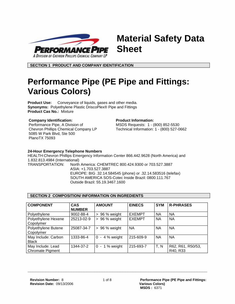
Material Safety Data Sheet
SECTION 1 PRODUCT AND COMPANY IDENTIFICATION
Performance Pipe (PE Pipe and Fittings: Various Colors) Product Use: Conveyance of liquids, gases and other media. Synonyms: Polyethylene Plastic DriscoPlex® Pipe and Fittings Product Cas No.: Mixture
Company Identification:
Performance Pipe, A Division of
Chevron Phillips Chemical Company LP
5085 W Park Blvd, Ste 500
PlanoTX 75093
Product Information: MSDS Requests: 1 - (800) 852-5530 Technical Information: 1 - (800) 527-0662
24-Hour Emergency Telephone Numbers HEALTH:Chevron Phillips Emergency Information Center 866.442.9628 (North America) and 1.832.813.4984 (International) TRANSPORTATION: North America: CHEMTREC 800.424.9300 or 703.527.3887 ASIA: +1.703.527.3887 EUROPE: BIG .32.14.584545 (phone) or .32.14.583516 (telefax) SOUTH AMERICA SOS-Cotec Inside Brazil: 0800.111.767 Outside Brazil: 55.19.3467.1600 SECTION 2 COMPOSITION/ INFORMATION ON INGREDIENTS
COMPONENT CAS
NUMBER AMOUNT EINECS SYM R-PHRASES
Polyethylene 9002-88-4 > 96 % weight EXEMPT NA NA Polyethylene Hexene Copolymer
25213-02-9 > 96 % weight EXEMPT NA NA
Polyethylene Butene Copolymer
25087-34-7 > 96 % weight NA NA NA
May Include: Carbon Black
1333-86-4 0 - 4 % weight 215-609-9 NA NA
May Include: Lead Chromate Pigment
1344-37-2 0 - 1 % weight 215-693-7 T, N R62, R61, R50/53, R40, R33
______________________________________________________________________
Revision Number: 8
Revision Date: 09/13/2006 1 of 8 Performance Pipe (PE Pipe and Fittings:
Various Colors)
MSDS : 6371

______________________________________________________________________
al Exposure Limits: L ing / Peak tion
Occupation Component Limit TWA STE Ceil Nota May Include: Carbon Black ACGIH 3.5 mg/m3 NA NA NA May Include: Carbon Black German MAK 6 mg/m3 NA NA NA May Include: Carbon Black OSHA PEL 3.5 mg/m3 NA NA NA May Include: Lead Chromate Pigment ACGIH .01 mg/m3 NA NA NA May Include: Lead Chromate Pigment German MAK .1 mg/m3 NA 4 NA May Include: Lead Chromate Pigment P OSHA S .05 mg/m3 NA NA NA Polyethylene ACGIH 3 mg/m3 NA NA NA Polyethylene CPCHEM Not Established NA NA NA Polyethylene German MAK 6 mg/m3 NA NA NA Polyethylene Butene Copolymer CPCHEM Not Established NA NA NA Polyethylene Hexene Copolymer CPCHEM Not Established NA NA NA SECTION 3 HAZARDS IDENTIFICATION
**************************************************************************************************************
lored plastic (various colors)
*******************************************************************
d or significant eye irritation. If this material is heated, thermal
he
hermal burns to the skin: may include pain or feeling of heat, discoloration,
is heated, fumes may be unpleasant nd produce nausea and irritation of the upper respiratory tract.
EMERGENCY OVERVIEW Co - FORMALDEHYDE MAY BE PRODUCED AT ELEVATED TEMPERATURE. *******************************************IMMEDIATE HEALTH EFFECTS: Eye: Not expected to cause prolongeburns may result from eye contact. Skin: Contact with the skin is not expected to cause prolonged or significant irritation. Contact with tskin is not expected to cause an allergic skin response. If this material is heated, thermal burns may result from skin contact. Tswelling, and blistering. Ingestion: Not expected to be harmful if swallowed. Inhalation: Not expected to be harmful if inhaled. If this materiala
SECTION 4 FIRST AID MEASURES Eye: If heated material should splash into eyes, flush eyes immediately with fresh water for 15 minutes
of vegetable
to drink and get
l respiration. If breathing ifficult, give oxygen. Get medical attention if breathing difficulties continue.
while holding the eyelids open. Remove contact lenses, if worn. Get immediate medical attention. Skin: If the hot material gets on skin, quickly cool in water. See a doctor for extensive burns. Do not try to peel the solidified material from the skin or use solvents or thinners to dissolve it. The useoil, mineral oil, or petroleum jelly is recommended for removal of this material from the skin. Ingestion: If swallowed, do not induce vomiting. Give the person a glass of water or milkimmediate medical attention. Never give anything by mouth to an unconscious person. Inhalation: Move the exposed person to fresh air. If not breathing, give artificiais d
SECTION 5 FIRE FIGHTING MEASURES FIRE CLASSIFICATION: Classification (29 C 91FR 1 0.1200): Not flammable or combustible. This material will burn although it is not easily ignited.
Revision Number: 8
Revision Date: 09/13/2006 2 of 8 Performance Pipe (PE Pipe and Fittings:
Various Colors)
MSDS : 6371

______________________________________________________________________
lth: 0 Flammability: 0 Reactivity: 0 ERTIES:
ammability (Explosive) Limits (% by volume in air): Lower: NA Upper: NA
ISHING MEDIA: Use water fog, foam, dry chemical or carbon dioxide (CO2) to extinguish mes.
es
fires d fire space without proper protective
ustion
g on temperature and air availability. ombustion may form: Carbon Dioxide, Carbon Monoxide
NFPA RATINGS: HeaFLAMMABLE PROPFlashpoint: NA Autoignition: NA Fl EXTINGUfla PROTECTION OF FIRE FIGHTERS: Fire Fighting Instructions: Material will not burn unless preheated. Clear fire area of all non-emergencypersonnel. Only enter confined fire space with full gear, including a positive pressure, NIOSH-approved, self-contained breathing apparatus. Cool surrounding equipment, fire-exposed containers and structurwith water. Container areas exposed to direct flame contact should be cooled with large quantities of water (500 gallons water per minute flame impingement exposure) to prevent weakening of container structure. If possible, water should be applied as a spray from a fogging nozzle since this is a surface burning material. The application of high velocity water will spread the burning surface layer. For involving this material, do not enter any enclosed or confineequipment, including self-contained breathing apparatus. Combustion Products: Incomplete combustion can also produce formaldehyde. Normal combforms carbon dioxide, water vapor and may produce carbon monoxide, original monomer, other hydrocarbons and hydrocarbon oxidation products, dependinC
SECTION 6 ACCIDENTAL RELEASE MEASURES Protective Measures: Eliminate all sources of ignition in vicinity of spilled material. Spill Management: If heated material is spilled, allow it to cool before proceeding with disposal methodReporting: U.S.A. regulations may require reporting spills of this material that could reach any surfacwaters. Report spills to lo
s. e
cal authorities and/or the National Response Center at (800) 424-8802 as propriate or required.
ap
SECTION 7 HANDLING AND STORAGE READ AND OBSERVE ALL PRECAUTIONS ON PRODUCT LABEL . REFER TO PRODUCT LABEL OR MANUFACTURERS TECHNICAL BULLETINS FOR THE PROPER USE AND HANDLING OF THIS MATERIAL .
ed material with eyes, skin, and clothing. Avoid
ldehyde,
n ll recommendations within this MSDS should minimize exposure to thermal
rocessing emissions.
Precautionary Measures: Avoid contact of heatbreathing vapor or fumes from heated material. Unusual Handling Hazards: Potentially toxic/irritating fumes may be evolved from heated material. At temperatures (>350°F, >177°C), polyethylenes can release vapors and gases, which are irritating to the mucous membranes of the eyes, mouth, throat, and lungs. These substances may include acetaacetone, acetic acid, formic acid, formaldehyde and acrolein. Based on animal data and limited epidemiological evidence, NTP, IARC (2A), and OSHA have listed formaldehyde as a probable humacarcinogen. Following ap
SECTION 8 EXPOSURE CONTROLS/PERSONAL PROTECTION GENERAL CONSIDERATIONS: Consider the potential hazards of this material (see Section 3), applicable exposure limits, job activities,
Revision Number: 8
Revision Date: 09/13/2006 3 of 8 Performance Pipe (PE Pipe and Fittings:
Various Colors)
MSDS : 6371

______________________________________________________________________
with the equipment since protection is ually provided for a limited time or under certain circumstances.
s, use process enclosures, local exhaust ventilation, or other gineering controls to control exposure.
event eye contact. If this material is heated,
revent skin contact if engineering
ot
otection. Use the following elements for air-purifying respirators: Organic Vapor and Formaldehyde.
cupational Exposure Limits:
L ng / Peak tion
and other substances in the work place when designing engineering controls and selecting personal protective equipment. If engineering controls or work practices are not adequate to prevent exposure to harmful levels of this material, the personal protective equipment listed below is recommended. The user should read and understand all instructions and limitations suppliedus ENGINEERING CONTROLS: If heated material generates vapor or fumeen PERSONAL PROTECTIVE EQUIPMENT: Eye/Face Protection: Wear eye protection such as safety glasses, chemical goggles, or faceshields if engineering controls or work practices are not adequate to prwear chemical goggles or safety glasses and a face shield. Skin Protection: If this material is heated, wear insulated clothing to pcontrols or work practices are not adequate to prevent skin contact. Respiratory Protection: If user operations generate harmful levels of airborne material that is nadequately controlled by ventilation, wear a NIOSH approved respirator that provides adequate pr Oc Component Limit TWA STE Ceili NotaMay Include: Carbon Black ACGIH 3.5 mg/m3 NA NA NA May Include: Carbon Black German MAK 6 mg/m3 NA NA NA May Include: Carbon Black OSHA PEL 3.5 mg/m3 NA NA NA May Include: Lead Chromate Pigment ACGIH .01 mg/m3 NA NA NA May Include: Lead Chromate Pigment German MAK .1 mg/m3 NA 4 NA May Include: Lead Chromate Pigment P OSHA S .05 mg/m3 NA NA NA Polyethylene ACGIH 3 mg/m3 NA NA NA Polyethylene CPCHEM Not Established NA NA NA Polyethylene German MAK 6 mg/m3 NA NA NA Polyethylene Butene Copolymer CPCHEM Not Established NA NA NA Polyethylene Hexene Copolymer CPCHEM Not Established NA NA NA SECTION 9 PHYSICAL AND CHEMICAL PROPERTIES
APPEARANCE AND ODOR: Colored plastic (various colors)
=1): NA
35°C (275°F)
ENSITY: 0.91 - 0.97 g/cm3
pH: NA VAPOR PRESSURE: NA VAPOR DENSITY (AIRBOILING POINT: NA SOLUBILITY (in water): Insoluble in water. MELTING POINT: 100°C (212°F) - 1SPECIFIC GRAVITY: 0.91 - 1.02D
SECTION 10 STABILITY AND REACTIVITY Chemical Stability: This material is considered stable under normal ambient and anticipated storage
ded processing temperature and handling conditions of temperature and pressure. Conditions to Avoid: heating above recommen
Revision Number: 8
Revision Date: 09/13/2006 4 of 8 Performance Pipe (PE Pipe and Fittings:
Various Colors)
MSDS : 6371

Incompatibility With Other Materials: None.
______________________________________________________________________
azardous Polymerization: Hazardous polymerization will not occur.
Hazardous Decomposition Products: Carbon Oxides. H
SECTION 11 TOXICOLOGICAL INFORMATION IMMEDIATE HEALTH EFFECTS:
cute Inhalation Toxicity: LC50 / not known
e eyes. itating to the skin.
nsitization: Dermal - not a sensitizer / human
nd
cinogen by NTP, IARC (2A), and OSHA based on animal data and limited epidemiological
vidence.
e
ent
e of these ments is likely to cause adverse health effects under recommended conditions of use.
Acute Oral Toxicity: LD50 / not known Acute Dermal Toxicity: LD50 / not known A Eye Irritation: Polyethylene:This material is not expected to be irritating to thSkin Irritation: This material is not expected to be irrSe ADDITIONAL TOXICOLOGY INFORMATION: This product contains POLYMERIZED OLEFINS. During thermal processing (>350°F, >177°C) polyolefins can release vapors and gases (aldehydes, ketones and organic acids) which are irritating to the mucous membranes of the eyes, mouth, throat, alungs. Generally these irritant effects are all transitory. However, prolonged exposure to irritating off-gases can lead to pulmonary edema. Formaldehyde (an aldehyde) has been classified as a probablehuman care Pigments containing carbon black, lead chromate, nickel, antimony,or titanium compounds may havbeen incorporated into this product. The International Agency for Research on Cancer (IARC) has classified carbon black as a Group 2B carcinogen (possibly carcinogenic to humans) based on sufficievidence in animals and inadequate evidence inhumans. However, the pigments in this product are bound in a polymer matrix which severely limits its extractability, bioavailability and toxicity. The lead chromate pigment is also silica-encapsulated as well as bound in the polymer matrix. Nonpig
SECTION 12 ECOLOGICAL INFORMATION ECOTOXICITY: This material is not expected to be harmful to aquatic organisms.
is material is not expected to be readily biodegradable.
ENVIRONMENTAL FATE: Th
SECTION 13 DISPOSAL CONSIDERATIONS Use material for its intended purpose or recycle if possible. This material as manufactured is a non hazardous waste but may be contaminated upon use. If this material must be discarded, depending onits use and application, it may meet the criteria of a hazardous waste as defined by the US EPA under RCRA (40 CFR 261) or other State and local regulations. Measurement of certain physical properties and analysis for regulated components may be necessary to make accurate determinations. If this material
is
Revision Number: 8
Revision Date: 09/13/2006 5 of 8 Performance Pipe (PE Pipe and Fittings:
Various Colors)
MSDS : 6371
______________________________________________________________________
as a hazardous waste, federal law requires disposal at a permitted hazardous aste disposal facility.
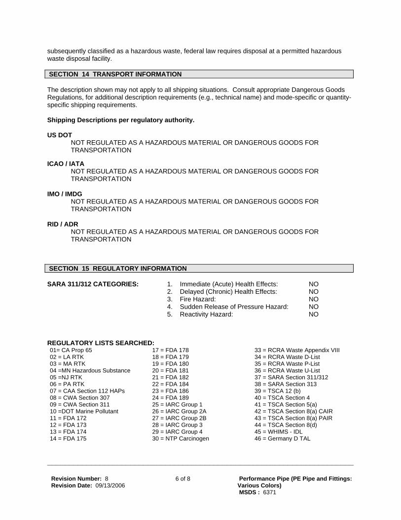
subsequently classified w SECTION 14 TRANSPORT INFORMATION The description shown may not apply to all shipping situations. Consult appropriate Dangerous Goods Regulations, for additional description requirements (e.g., technical name) and mode-specific or quantity-
ecific shipping requirements.
ipping Descriptions per regulatory authority.
US DOT A HAZARDOUS MATERIAL OR DANGEROUS GOODS FOR
RANSPORTATION
ICAO / A HAZARDOUS MATERIAL OR DANGEROUS GOODS FOR
TRANSPORTATION
IMO / IM A HAZARDOUS MATERIAL OR DANGEROUS GOODS FOR
TRANSPORTATION
RID / AD HAZARDOUS MATERIAL OR DANGEROUS GOODS FOR
TRANSPORTATION
sp Sh
NOT REGULATED AST IATA NOT REGULATED AS
DG NOT REGULATED AS
R
NOT REGULATED AS A
SECTION 15 REGULATORY INFORMATION SA 1 C O 1. Immediate (Acute) Health Effects: NO RA 3 1/312 ATEG RIES:
5. Reactivity Hazard: NO
ISTS SEARCHED5 ix VIII
rdous Substance 12
3 3 APs
e Pollutant AIR
8 )
2. Delayed (Chronic) Health Effects: NO 3. Fire Hazard: NO 4. Sudden Release of Pressure Hazard: NO REGULATORY L : 01= CA Prop 6 17 = FDA 178 33 = RCRA Waste Append 02 = LA RTK 18 = FDA 179 34 = RCRA Waste D-List 03 = MA RTK 19 = FDA 180 35 = RCRA Waste P-List 04 =MN Haza 20 = FDA 181 36 = RCRA Waste U-List 05 =NJ RTK 21 = FDA 182 37 = SARA Section 311/3 06 = PA RTK 22 = FDA 184 38 = SARA Section 1
39 = TSCA 12 (b) 07 = CAA Section 112 H 23 = FDA 186 08 = CWA Section 307 24 = FDA 189 40 = TSCA Section 4 09 = CWA Section 311 25 = IARC Group 1 41 = TSCA Section 5(a) 10 =DOT Marin 26 = IARC Group 2A 42 = TSCA Section 8(a) CAIR 11 = FDA 172 27 = IARC Group 2B 43 = TSCA Section 8(a) P 12 = FDA 173 28 = IARC Group 3 44 = TSCA Section (d
45 = WHIMS - IDL 13 = FDA 174 29 = IARC Group 4 14 = FDA 175 30 = NTP Carcinogen 46 = Germany D TAL
Revision Number: 8
Revision Date: 09/13/2006 6 of 8 Performance Pipe (PE Pipe and Fittings:
Various Colors)
MSDS : 6371

______________________________________________________________________
5 = FDA 176 1 = OSHA Carcinogen G 6 = FDA 177 2 = OSHA Highly Hazardous 48 = DEA List 1
49 = DEA List 2
of this material are fou y lists indicated.
ay Include: Carbon Black 1, 3, 4, 5, 6, 27, 45 ay Include: Lead Chromate Pigment 1, 3, 4, 5, 6, 25, 26, 30, 34, 38, 39, 45, 46
( R NG S(TPQ): nent RQ nent TPQ
1 3 47 = Germany WK 1 3
The following components nd on the regulator Polyethylene 4 M M CERCLA REPORTABLE QUANTITIES
mponent RQ)/SARA Compo
302 TH ESHOLD Compo
PLANNI QUANTITI Product RQ
E Co May Include: Lead Chromate Pigment 10 lbs None 1000 lbs WHMIS CLASSIFICATI
is product is not consiON: dered a controlled product according to the criteria of the Canadian Controlled
cts Regulations.
e. irements..
PHILIPP irements. e TSCA inventory, but is
ADA: This product is exempt from inventory listing requirements.
Symbols: NA - Not Applicable
ThProdu CHEMICAL INVENTORY LISTINGS:
XEMPTION for usPEOPLE'S REPUBLIC OF CHINA: This product is subject to special EEUROPEAN UNION (EU): This product is exempt from inventory listing requKOREA: This product is exempt from inventory listing requirements.
INES: This product is exempt from inventory listing requUNITED STATES: This product or a component of this product is not on th
subject to special EXEMPTION for use in Commerce. USTRALIA: This product is exempt from inventory listing requirements. A
CAN EU
SECTION 16 OTHER INFORMATION
NFPA RATINGS: Health: 0 Flammability: 0 Reactivity: 0 Special: NA (0-Least, 1-Slight, 2-Moderate, 3-High, 4-Extreme, PPE:- Personal Protection Equipment Index recommendation, *- Chronic Effect Indicator). These values are obtained using the guidelines or
FPA).
ABBREVIATIONS THAT MAY HAVE BEEN USED IN THIS DOCUMENT:
STEL - Limit PEL - osure Limit nt
ists Administration
published evaluations prepared by the National Fire Protection Association (N REVISION STATEMENT: The following sections have been updated: 2, 15
TLV -
Threshold Limit Value TWA - Time Weighted Average
Short-term Exposure Permissible Exp ACGIH - American Conference of Governme
Industrial Hygien OSHA - Occupational Safety & Health
Revision Number: 8
Revision Date: 09/13/2006 7 of 8 Performance Pipe (PE Pipe and Fittings:
Various Colors)
MSDS : 6371

______________________________________________________________________
l Substances
very Act
and ol Act
tion ation 0 S
= - Less Than or Equal To >= - Greater Than or Equal To NS - Central Nervous System MAK - Germany Maximum Concentration Values
ared according to the latest adaptation of the EEC Guideline 67/548. tandard (29 CFR
(Z400.1). his data sheet was prepared by EHS Product Stewardship Group, Chevron Phillips Chemical
mpany LP, 10001 Six Pines Drive, The Woodlands, TX 77380.
NIOSH - National Institute for OccupationalSafety & Health
NFPA - National Fire Protection Agency
WHMIS -
Workplace Hazardous MaterialsInformation System
IARC - Intl. Agency for Research on Cancer
EINECS -
European Inventory of existingCommercial Chemica
RCRA - Resource Conservation Reco
SARA -
Superfund AmendmentsReauthorization Act.
TSCA - Toxic Substance Contr
EC50 - Effective Concentra LC50 - Lethal Concentr LD5 - Lethal Dose CA - Chemical Abstract Service NDA - No Data Available NA - Not Applicable < C This data sheet is prepThis data sheet is prepared according to the OSHA Hazard Communication S1910.1200). This data sheet is prepared according to the ANSI MSDS StandardTCo
d y
for the results of information is furnished upon condition that the person receiving it shall make his
wn determination of the suitability of the material for his particular purpose.
The above information is based on the data of which we are aware and is believed to be correct as of the date hereof. Since this information may be applied under conditions beyond our control anwith which we may be unfamiliar and since data made available subsequent to the date hereof masuggest modifications of the information, we do not assume any responsibilityits use. Thiso
Revision Number: 8
Revision Date: 09/13/2006 8 of 8 Performance Pipe (PE Pipe and Fittings:
Various Colors)
MSDS : 6371

TechData PRODUCT SPECIFICATION SHEET ProGeo High Density Polyethylene Socket Heat Fusion Fittings For Water Source Earth-Coupled Heat Pump Systems Scope This product specification designates the requirements for ProGeo high density polyethylene (HDPE) socket heat fusion fittings to be used as connections for Iron Pipe Size outside diameter (IPS-OD) controlled HDPE pipe in ¾”, 1”, 1 ¼”, 1 ½”, and 2” sizes. Materials ProGeo HDPE socket heat fusion fittings are manufactured from a bimodal polyethylene resin PE4710 with a cell classification, PE345564C per ASTM D-3350. This high performance resin exhibits enhanced performance properties including superior Slow Crack Growth (SCG) resistance plus improved tensile strength and modulus. ProGeo socket fusion by metallic adapter fittings are manufactured using machined components of brass alloy B360 per ASTM B-16. Recommended Uses ProGeo socket heat fusion fittings are intended and recommended for use in open or closed loop, water source earth coupled heat pump systems installed with IPS-OD, HDPE pipe manufactured to a minimum pressure rating of SDR11 or Schedule 40. Handling and Installation ProGeo socket heat fusion fittings shall be installed in accordance with industry accepted and approved procedures, applicable code requirements and current assembly guidelines available from Viega, LLC. Prior to installation, ProGeo socket heat fusion fittings should be stored in a clean, dry location.

A B C D E F G H I657294 YFPC44 1.020 ±.008 1.012 +.008 -.012 .625 Min. 1.020 ±.008 1.012 +.008 -.012 .625 Min.657295 YFPC54 1.275 ±.008 1.267 +.008 -.012 .687 Min. 1.020 ±.008 1.012 +.008 -.012 .625 Min.657296 YFPC55 1.275 ±.008 1.267 +.008 -.012 .687 Min. 1.275 ±.008 1.267 +.008 -.012 .687 Min.657297 YFPC64 1.620±.008 1.612 +.008 -.016 .875 Min. 1.020 ±.008 1.012 +.008 -.012 .625 Min.657298 YFPC65 1.620±.008 1.612 +.008 -.016 .875 Min. 1.275 ±.008 1.267 +.008 -.012 .687 Min.657299 YFPC66 1.620±.008 1.612 +.008 -.016 .875 Min. 1.620±.008 1.612 +.008 -.016 .875 Min.657301 YFPC74 1.860±.010 1.849 +.010 -.020 .875 Min. 1.020 ±.008 1.012 +.008 -.012 .625 Min.657302 YFPC75 1.860±.010 1.849 +.010 -.020 .875 Min. 1.275 ±.008 1.267 +.008 -.012 .687 Min.657303 YFPC76 1.860±.010 1.849 +.010 -.020 .875 Min. 1.620±.008 1.612 +.008 -.016 .875 Min.657304 YFPC77 1.860±.010 1.849 +.010 -.020 .875 Min. 1.860±.010 1.849 +.010 -.020 .875 Min.657305 YFPC85 2.235±.010 2.324 +.010 -.020 .875 Min. 1.275 ±.008 1.267 +.008 -.012 .687 Min.657306 YFPC86 2.235±.010 2.324 +.010 -.020 .875 Min. 1.620±.008 1.612 +.008 -.016 .875 Min.657307 YFPC87 2.235±.010 2.324 +.010 -.020 .875 Min. 1.620±.008 1.612 +.008 -.016 .875 Min.657308 YFPC88 2.235±.010 2.324 +.010 -.020 .875 Min. 2.235±.010 2.324 +.010 -.020 .875 Min.
A B C D E F G H I657309 YFPCP4 1.020 ±.008 1.012 +.008 -.012 .625 Min.657310 YFPCP5 1.275 ±.008 1.267 +.008 -.012 .687 Min.657311 YFPCP6 1.620±.008 1.612 +.008 -.016 .875 Min.657312 YFPCP7 1.860±.010 1.849 +.010 -.020 .875 Min.657313 YFPCP8 2.235±.010 2.324 +.010 -.020 .875 Min.
DRAWING NUMBER
SAP NUMBER
Couplers
SAP NUMBER
DRAWING NUMBER
DIMENSIONS
DIMENSIONS
Caps
A D
C F
B E
BA
C
Geo Fitting Spec. Sheet Page 1

A B C D E F G H I657315 YFPE44 1.020 ±.008 1.012 +.008 -.012 .625 Min. 1.020 ±.008 1.012 +.008 -.012 .625 Min.657317 YFPE54 1.275 ±.008 1.267 +.008 -.012 .687 Min. 1.020 ±.008 1.012 +.008 -.012 .625 Min.657318 YFPE55 1.275 ±.008 1.267 +.008 -.012 .687 Min. 1.275 ±.008 1.267 +.008 -.012 .687 Min.
YFPE64 1.620±.008 1.612 +.008 -.016 .875 Min. 1.020 ±.008 1.012 +.008 -.012 .625 Min.657322 YFPE65 1.620±.008 1.612 +.008 -.016 .875 Min. 1.275 ±.008 1.267 +.008 -.012 .687 Min.657323 YFPE66 1.620±.008 1.612 +.008 -.016 .875 Min. 1.620±.008 1.612 +.008 -.016 .875 Min.657326 YFPE77 1.860±.010 1.849 +.010 -.020 .875 Min. 1.860±.010 1.849 +.010 -.020 .875 Min.657327 YFPE86 2.235±.010 2.324 +.010 -.020 .875 Min. 1.620±.008 1.612 +.008 -.016 .875 Min.657945 YFPE88 2.235±.010 2.324 +.010 -.020 .875 Min. 2.235±.010 2.324 +.010 -.020 .875 Min.
A B C D E F G H I657331 YFPEU44 1.020 ±.008 1.012 +.008 -.012 .625 Min. 3/4" PIPE STUB657332 YFPEU55 1.275 ±.008 1.267 +.008 -.012 .687 Min. 1" PIPE STUB657333 YFPEU66F 1.620±.008 1.612 +.008 -.016 .875 Min. 1 1/4" FEMALE657334 YFPEU66M 1.620±.008 1.612 +.008 -.016 .875 Min. 1 1/4" PIPE STUB
SAP NUMBER
DRAWING NUMBER
DIMENSIONS
90° Elbows
90° U-Bend Elbows
SAP NUMBER
DRAWING NUMBER
DIMENSIONS
B A
C
F
ED
C
D
AB
Geo Fitting Spec. Sheet Page 2

A B C D E F G H I657335 YFPF45 1.020 ±.008 1.012 +.008 -.012 .625 Min.657337 YFPFF4 1.020 ±.008 1.012 +.008 -.012 .625 Min.657338 YFPFF5 1.275 ±.008 1.267 +.008 -.012 .687 Min. * SLIM FLANGE657340 YFPFF6 1.620±.008 1.612 +.008 -.016 .875 Min.657341 YFPFF8 2.235±.010 2.324 +.010 -.020 .875 Min.
A B C D E F G H I657342 YFPFT554 1.275 ±.008 1.267 +.008 -.012 .687 Min. 1" PIPE STUB 1.020 ±.008 1.012 +.008 -.012 .625 Min.657343 YFPFT555 1.275 ±.008 1.267 +.008 -.012 .687 Min. 1" PIPE STUB 1.275 ±.008 1.267 +.008 -.012 .687 Min.657344 YFPFT654 1.620±.008 1.612 +.008 -.016 .875 Min. 1" PIPE STUB 1.020 ±.008 1.012 +.008 -.012 .625 Min.
YFPFT655 1.620±.008 1.612 +.008 -.016 .875 Min. 1" PIPE STUB 1.275 ±.008 1.267 +.008 -.012 .687 Min.657346 YFPFT664 1.620±.008 1.612 +.008 -.016 .875 Min. 1 1/4" PIPE STUB 1.020 ±.008 1.012 +.008 -.012 .625 Min.657347 YFPFT665 1.620±.008 1.612 +.008 -.016 .875 Min. 1 1/4" PIPE STUB 1.275 ±.008 1.267 +.008 -.012 .687 Min.
SAP NUMBER
DRAWING NUMBER
DIMENSIONS
Header Tees
Flanges
SAP NUMBER
DRAWING NUMBER
DIMENSIONS
BA
C
C
BA D
G
FE
Geo Fitting Spec. Sheet Page 3

A B C D E F G H I657348 YFPMA44 1.020 ±.008 1.012 +.008 -.012 .625 Min. 3/4" MPT657349 YFPMA45 1.020 ±.008 1.012 +.008 -.012 .625 Min. 1" MPT657350 YFPMA54 1.275 ±.008 1.267 +.008 -.012 .687 Min. 3/4" MPT657351 YFPMA55 1.275 ±.008 1.267 +.008 -.012 .687 Min. 1" MPT657352 YFPMA64 1.620±.008 1.612 +.008 -.016 .875 Min. 3/4" MPT657353 YFPMA65 1.620±.008 1.612 +.008 -.016 .875 Min. 1" MPT657354 YFPMA66 1.620±.008 1.612 +.008 -.016 .875 Min. 1 1/4" MPT657355 YFPMA67 1.620±.008 1.612 +.008 -.016 .875 Min. 1 1/2" MPT657356 YFPMA77 1.860±.010 1.849 +.010 -.020 .875 Min. 1 1/2" MPT657357 YFPMA86 2.235±.010 2.324 +.010 -.020 .875 Min. 1 1/4" MPT657358 YFPMA87 2.235±.010 2.324 +.010 -.020 .875 Min. 1 1/2" MPT657359 YFPMA88 2.235±.010 2.324 +.010 -.020 .875 Min. 2" MPT
A B C D E F G H I657360 YFPMC45S 1.020 ±.008 1.012 +.008 -.012 .625 Min. 1" MNT
YFPMC55S 1.275 ±.008 1.267 +.008 -.012 .687 Min. 1" MNT657362 YFPMC56S 1.275 ±.008 1.267 +.008 -.012 .687 Min. 1 1/4" MNT657363 YFPMC65S 1.620±.008 1.612 +.008 -.016 .875 Min. 1" MNT657364 YFPMC66S 1.620±.008 1.612 +.008 -.016 .875 Min. 1 1/4" MNT
DIMENSIONS
Male Pipe Thread Adapters
SAP NUMBER
Male Nominal Thread Adapter Couplers
SAP NUMBER
DRAWING NUMBER
DRAWING NUMBER
DIMENSIONS
A B
CD
BA
C D
Geo Fitting Spec. Sheet Page 4

A B C D E F G H I657365 YFPME45S 1.020 ±.008 1.012 +.008 -.012 .625 Min. 1" MNT657368 YFPME55S 1.275 ±.008 1.267 +.008 -.012 .687 Min. 1" MNT657366 YFPME54 1.275 ±.008 1.267 +.008 -.012 .687 Min. 3/4" MPT657367 YFPME55 1.275 ±.008 1.267 +.008 -.012 .687 Min. 1" MPT657369 YFPME65 1.620±.008 1.612 +.008 -.016 .875 Min. 1" MPT657370 YFPME66 1.620±.008 1.612 +.008 -.016 .875 Min. 1 1/4" MPT
A B C D E F G H I657371 YFPMT355 1/2" FPT 1" MNT 1.275 ±.008 1.267 +.008 -.012 .687 Min.
657372 YFPMT453 1.020 ±.008 1.012 +.008 -.012 .625 Min. 1" MNT 1/2" FPT657373 YFPMT553 1.275 ±.008 1.267 +.008 -.012 .687 Min. 1" MPT 1/2" FPT
657374 YFPMT555S 1.275 ±.008 1.267 +.008 -.012 .687 Min. 1.275 ±.008 1.267 +.008 -.012 .687 Min. 1" MNT657375 YFPMT665S 1.620±.008 1.612 +.008 -.016 .875 Min. 1.620±.008 1.612 +.008 -.016 .875 Min. 1" MNT
90° Male Adapter Elbows
SAP NUMBER
DRAWING NUMBER
DIMENSIONS
Male Thread Adapter Tees
SAP NUMBER
DRAWING NUMBER
DIMENSIONS
A B
D
C
DC
E
AB
BA
C
D
E
BA
C F
E D
G
Geo Fitting Spec. Sheet Page 5

A B C D E F G H I657376 YFPSA45 1.020 ±.008 1.012 +.008 -.012 .625 Min. 1" FNT SWIVEL657377 YFPSA55 1.275 ±.008 1.267 +.008 -.012 .687 Min. 1" FNT SWIVEL657378 YFPSA65 1.620±.008 1.612 +.008 -.016 .875 Min. 1" FNT SWIVEL
A B C D E F G H I657379 YFPSC42 1.020 ±.008 1.012 +.008 -.012 .625 Min. 1/4" FPT657380 YFPSC43 1.020 ±.008 1.012 +.008 -.012 .625 Min. 1/2" FPT657381 YFPSC52 1.275 ±.008 1.267 +.008 -.012 .687 Min. 1/4" FPT657382 YFPSC53 1.275 ±.008 1.267 +.008 -.012 .687 Min. 1/2" FPT657383 YFPSC54 1.275 ±.008 1.267 +.008 -.012 .687 Min. 3/4" FPT
A B C D E F G H I657384 YFPSE43 1.020 ±.008 1.012 +.008 -.012 .625 Min. 1/2" FPT657385 YFPSE44 1.020 ±.008 1.012 +.008 -.012 .625 Min. 3/4" FPT
SAP NUMBER
Female Thread Swivel Adapters
SAP NUMBER
DRAWING NUMBER
DIMENSIONS
DRAWING NUMBER
DIMENSIONS
Female Pipe Thread Adapters
DRAWING NUMBER
DIMENSIONS
Female Pipe Thread Adapter 90° Elbows
SAP NUMBER
BA
C
D
BA
C
D
BA
C
D
Geo Fitting Spec. Sheet Page 6

A B C D E F G H I657386 YFPST443 1.020 ±.008 1.012 +.008 -.012 .625 Min. 1.020 ±.008 1.012 +.008 -.012 .625 Min. 1/2" FPT657387 YFPST553 1.275 ±.008 1.267 +.008 -.012 .687 Min. 1.275 ±.008 1.267 +.008 -.012 .687 Min. 1/2" FPT
A B C D E F G H I657388 YFPT444 1.020 ±.008 1.012 +.008 -.012 .625 Min. 1.020 ±.008 1.012 +.008 -.012 .625 Min. 1.020 ±.008 1.012 +.008 -.012 .625 Min.657389 YFPT554 1.275 ±.008 1.267 +.008 -.012 .687 Min. 1.275 ±.008 1.267 +.008 -.012 .687 Min. 1.020 ±.008 1.012 +.008 -.012 .625 Min.657390 YFPT555 1.275 ±.008 1.267 +.008 -.012 .687 Min. 1.275 ±.008 1.267 +.008 -.012 .687 Min. 1.275 ±.008 1.267 +.008 -.012 .687 Min.657391 YFPT644 1.620±.008 1.612 +.008 -.016 .875 Min. 1.020 ±.008 1.012 +.008 -.012 .625 Min. 1.020 ±.008 1.012 +.008 -.012 .625 Min.657392 YFPT655 1.620±.008 1.612 +.008 -.016 .875 Min. 1.275 ±.008 1.267 +.008 -.012 .687 Min. 1.275 ±.008 1.267 +.008 -.012 .687 Min.657393 YFPT664 1.620±.008 1.612 +.008 -.016 .875 Min. 1.620±.008 1.612 +.008 -.016 .875 Min. 1.020 ±.008 1.012 +.008 -.012 .625 Min.657394 YFPT665 1.620±.008 1.612 +.008 -.016 .875 Min. 1.620±.008 1.612 +.008 -.016 .875 Min. 1.275 ±.008 1.267 +.008 -.012 .687 Min.657396 YFPT666 1.620±.008 1.612 +.008 -.016 .875 Min. 1.620±.008 1.612 +.008 -.016 .875 Min. 1.620±.008 1.612 +.008 -.016 .875 Min.657397 YFPT775 1.860±.010 1.849 +.010 -.020 .875 Min. 1.860±.010 1.849 +.010 -.020 .875 Min. 1.275 ±.008 1.267 +.008 -.012 .687 Min.657398 YFPT777 1.860±.010 1.849 +.010 -.020 .875 Min. 1.860±.010 1.849 +.010 -.020 .875 Min. 1.860±.010 1.849 +.010 -.020 .875 Min.657399 YFPT866 2.235±.010 2.324 +.010 -.020 .875 Min. 1.620±.008 1.612 +.008 -.016 .875 Min. 1.620±.008 1.612 +.008 -.016 .875 Min.657400 YFPT884 2.235±.010 2.324 +.010 -.020 .875 Min. 2.235±.010 2.324 +.010 -.020 .875 Min. 1.020 ±.008 1.012 +.008 -.012 .625 Min.657401 YFPT885 2.235±.010 2.324 +.010 -.020 .875 Min. 2.235±.010 2.324 +.010 -.020 .875 Min. 1.275 ±.008 1.267 +.008 -.012 .687 Min.657402 YFPT886 2.235±.010 2.324 +.010 -.020 .875 Min. 2.235±.010 2.324 +.010 -.020 .875 Min. 1.620±.008 1.612 +.008 -.016 .875 Min.657403 YFPT888 2.235±.010 2.324 +.010 -.020 .875 Min. 2.235±.010 2.324 +.010 -.020 .875 Min. 2.235±.010 2.324 +.010 -.020 .875 Min.
SAP NUMBER
DRAWING NUMBER
DIMENSIONS
Tees
SAP NUMBER
DRAWING NUMBER
DIMENSIONS
Female Pipe Thread Adapter Tees
BA
C
E D
F
G
BA E D
C F
HG
I
Geo Fitting Spec. Sheet Page 7

Product Name: Polyethylene 53050E High Density Issue Date: 10/30/2008 Print Date: 31 Oct 2008
®(TM)*Trademark of The Dow Chemical Company ("Dow") or an affiliated company of Dow
Page 1 of 7
The Dow Chemical Company encourages and expects you to read and understand the entire (M)SDS, as there is important information throughout the document. We expect you to follow the precautions identified in this document unless your use conditions would necessitate other appropriate methods or actions.
1. Product and Company Identification Product Name
Polyethylene 53050E High Density COMPANY IDENTIFICATION The Dow Chemical Company 2030 Willard H. Dow Center Midland, MI 48674 USA Customer Information Number: 800-258-2436 EMERGENCY TELEPHONE NUMBER24-Hour Emergency Contact: 989-636-4400 Local Emergency Contact: 989-636-4400
2. Hazards Identification Emergency Overview Color: White Physical State: Pellets Odor: Odorless Hazards of product:
Slipping hazard.
OSHA Hazard Communication Standard This product is not a "Hazardous Chemical" as defined by the OSHA Hazard Communication Standard, 29 CFR 1910.1200. Potential Health Effects Eye Contact: Solid or dust may cause irritation or corneal injury due to mechanical action. Elevated temperatures may generate vapor levels sufficient to cause eye irritation. Effects may include discomfort and redness. Skin Contact: Prolonged contact is essentially nonirritating to skin. Mechanical injury only. Under normal processing conditions, material is heated to elevated temperatures; contact with the material may cause thermal burns.
Material Safety Data Sheet The Dow Chemical Company
Product Name: Polyethylene 53050E High Density Issue Date: 10/30/2008
Page 2 of 7
Skin Absorption: No adverse effects anticipated by skin absorption. Inhalation: No adverse effects are anticipated from single exposure to dust. Vapors/fumes released during thermal processing may cause respiratory irritation. Ingestion: Very low toxicity if swallowed. Harmful effects not anticipated from swallowing small amounts. May cause choking if swallowed.
Component CAS # Amount
1-Butene, polymer with ethene 25087-34-7 > 99.0 %
4. First-aid measures Eye Contact: Flush eyes thoroughly with water for several minutes. Remove contact lenses after the initial 1-2 minutes and continue flushing for several additional minutes. If effects occur, consult a physician, preferably an ophthalmologist. Skin Contact: If molten material comes in contact with the skin, do not apply ice but cool under ice water or running stream of water. DO NOT attempt to remove the material from skin. Removal could result in severe tissue damage. Seek medical attention immediately. Inhalation: Move person to fresh air; if effects occur, consult a physician. Ingestion: If swallowed, seek medical attention. May cause gastrointestinal blockage. Do not give laxatives. Do not induce vomiting unless directed to do so by medical personnel. Notes to Physician: If burn is present, treat as any thermal burn, after decontamination. No specific antidote. Treatment of exposure should be directed at the control of symptoms and the clinical condition of the patient.
5. Fire Fighting Measures Extinguishing Media: Water fog or fine spray. Dry chemical fire extinguishers. Carbon dioxide fire extinguishers. Foam. Fire Fighting Procedures: Keep people away. Isolate fire and deny unnecessary entry. Soak thoroughly with water to cool and prevent re-ignition. If material is molten, do not apply direct water stream. Use fine water spray or foam. Cool surroundings with water to localize fire zone. Hand held dry chemical or carbon dioxide extinguishers may be used for small fires. Special Protective Equipment for Firefighters: Wear positive-pressure self-contained breathing apparatus (SCBA) and protective fire fighting clothing (includes fire fighting helmet, coat, trousers, boots, and gloves). If protective equipment is not available or not used, fight fire from a protected location or safe distance. Unusual Fire and Explosion Hazards: Pneumatic conveying and other mechanical handling operations can generate combustible dust. To reduce the potential for dust explosions, do not permit dust to accumulate. Dense smoke is emitted when burned without sufficient oxygen. Hazardous Combustion Products: During a fire, smoke may contain the original material in addition to combustion products of varying composition which may be toxic and/or irritating. Combustion products may include and are not limited to: Carbon monoxide. Carbon dioxide.
6. Accidental Release Measures Steps to be Taken if Material is Released or Spilled: Contain spilled material if possible. Sweep up. Collect in suitable and properly labeled containers. See Section 13, Disposal Considerations, for additional information. Personal Precautions: Spilled material may cause a slipping hazard. Use appropriate safety equipment. For additional information, refer to Section 8, Exposure Controls and Personal Protection.
3. Composition Information

Product Name: Polyethylene 53050E High Density Issue Date: 10/30/2008
Page 3 of 7
Environmental Precautions: Prevent from entering into soil, ditches, sewers, waterways and/or groundwater. See Section 12, Ecological Information.
7. Handling and Storage Handling General Handling: No smoking, open flames or sources of ignition in handling and storage area. Good housekeeping and controlling of dusts are necessary for safe handling of product. Avoid breathing process fumes. Use with adequate ventilation. When appropriate, unique handling information for containers can be found on the product label. Workers should be protected from the possibility of contact with molten resin. Do not get molten material in eyes, on skin or clothing. Pneumatic conveying and other mechanical handling operations can generate combustible dust. To reduce the potential for dust explosions, electrically bond and ground equipment and do not permit dust to accumulate. Dust can be ignited by static discharge. Storage Store in accordance with good manufacturing practices.
8. Exposure Controls / Personal Protection Exposure Limits None established Personal Protection Eye/Face Protection: Use safety glasses. If there is a potential for exposure to particles which could cause eye discomfort, wear chemical goggles. If exposure causes eye discomfort, use a full-face respirator. Skin Protection: No precautions other than clean body-covering clothing should be needed.
Hand protection: Chemical protective gloves should not be needed when handling this material. Consistent with general hygienic practice for any material, skin contact should be minimized. Use gloves to protect from mechanical injury. Selection of gloves will depend on the task. Use gloves with insulation for thermal protection, when needed.
Respiratory Protection: Respiratory protection should be worn when there is a potential to exceed the exposure limit requirements or guidelines. If there are no applicable exposure limit requirements or guidelines, wear respiratory protection when adverse effects, such as respiratory irritation or discomfort have been experienced, or where indicated by your risk assessment process. Use an approved air-purifying respirator when vapors are generated at increased temperatures or when dust or mist is present. The following should be effective types of air-purifying respirators: When dust/mist are present use a/an Particulate filter. When combinations of vapors, acids, or dusts/mists are present use a/an Organic vapor cartridge with a particulate pre-filter. Ingestion: Use good personal hygiene. Do not consume or store food in the work area. Wash hands before smoking or eating. Engineering Controls Ventilation: Use local exhaust ventilation, or other engineering controls to maintain airborne levels below exposure limit requirements or guidelines. If there are no applicable exposure limit requirements or guidelines, general ventilation should be sufficient for most operations. Local exhaust ventilation may be necessary for some operations.
9. Physical and Chemical Properties Physical State Pellets Color White
Product Name: Polyethylene 53050E High Density Issue Date: 10/30/2008
Page 4 of 7
Odor Odorless Flash Point - Closed Cup Not applicable Flammable Limits In Air Lower: Not applicable Upper: Not applicable Autoignition Temperature No test data available Vapor Pressure Not applicable Boiling Point (760 mmHg) Not applicable. Vapor Density (air = 1) Not applicable Specific Gravity (H2O = 1) 0.83 - 0.97 Supplier Freezing Point Not applicable Melting Point Supplier Varies Solubility in Water (by weight)
Negligible
pH Not applicable Decomposition Temperature
No test data available
Partition coefficient, n-octanol/water (log Pow)
No data available for this product.
Kinematic Viscosity Not applicable
10. Stability and Reactivity Stability/Instability Stable. Conditions to Avoid: Exposure to elevated temperatures can cause product to decompose. Incompatible Materials: None known. Hazardous Polymerization Will not occur. Thermal Decomposition Decomposition products depend upon temperature, air supply and the presence of other materials. Processing may release fumes and other decomposition products. At temperatures exceeding melt temperatures, polymer fragments can be released. Fumes can be irritating. Decomposition products can include and are not limited to: Aldehydes. Alcohols. Organic acids. Decomposition products can include trace amounts of: Hydrocarbons.
11. Toxicological Information
Acute Toxicity Ingestion Estimated LD50, Rat > 5,000 mg/kg Skin Absorption Estimated LD50, Rabbit > 2,000 mg/kg Repeated Dose Toxicity Additives are encapsulated in the product and are not expected to be released under normal processing conditions or foreseeable emergency. Chronic Toxicity and Carcinogenicity No relevant information found. Developmental Toxicity No relevant information found. Reproductive Toxicity No relevant information found. Genetic Toxicology No relevant information found.
Product Name: Polyethylene 53050E High Density Issue Date: 10/30/2008
Page 5 of 7
12. Ecological Information ENVIRONMENTAL FATE Movement & Partitioning No bioconcentration is expected because of the relatively high molecular weight (MW greater than 1000). In the terrestrial environment, material is expected to remain in the soil. In the aquatic environment, material is expected to float. Persistence and Degradability This water-insoluble polymeric solid is expected to be inert in the environment. Surface photodegradation is expected with exposure to sunlight. No appreciable biodegradation is expected. ECOTOXICITY Not expected to be acutely toxic, but material in pellet or bead form may mechanically cause adverse effects if ingested by waterfowl or aquatic life.
13. Disposal Considerations DO NOT DUMP INTO ANY SEWERS, ON THE GROUND, OR INTO ANY BODY OF WATER. All disposal practices must be in compliance with all Federal, State/Provincial and local laws and regulations. Regulations may vary in different locations. Waste characterizations and compliance with applicable laws are the responsibility solely of the waste generator. AS YOUR SUPPLIER, WE HAVE NO CONTROL OVER THE MANAGEMENT PRACTICES OR MANUFACTURING PROCESSES OF PARTIES HANDLING OR USING THIS MATERIAL. THE INFORMATION PRESENTED HERE PERTAINS ONLY TO THE PRODUCT AS SHIPPED IN ITS INTENDED CONDITION AS DESCRIBED IN MSDS SECTION: Composition Information. FOR UNUSED & UNCONTAMINATED PRODUCT, the preferred options include sending to a licensed, permitted: Recycler. Reclaimer. Incinerator or other thermal destruction device. Landfill.
14. Transport Information DOT Non-Bulk NOT REGULATED DOT Bulk NOT REGULATED IMDG NOT REGULATED ICAO/IATA NOT REGULATED This information is not intended to convey all specific regulatory or operational requirements/information relating to this product. Additional transportation system information can be obtained through an authorized sales or customer service representative. It is the responsibility of the transporting organization to follow all applicable laws, regulations and rules relating to the transportation of the material.
Product Name: Polyethylene 53050E High Density Issue Date: 10/30/2008
Page 6 of 7
15. Regulatory Information OSHA Hazard Communication Standard This product is not a "Hazardous Chemical" as defined by the OSHA Hazard Communication Standard, 29 CFR 1910.1200. Superfund Amendments and Reauthorization Act of 1986 Title III (Emergency Planning and Community Right-to-Know Act of 1986) Sections 311 and 312 Immediate (Acute) Health Hazard No Delayed (Chronic) Health Hazard No Fire Hazard No Reactive Hazard No Sudden Release of Pressure Hazard No Superfund Amendments and Reauthorization Act of 1986 Title III (Emergency Planning and Community Right-to-Know Act of 1986) Section 313 To the best of our knowledge, this product does not contain chemicals at levels which require reporting under this statute. Pennsylvania (Worker and Community Right-To-Know Act): Pennsylvania Hazardous Substances List and/or Pennsylvania Environmental Hazardous Substance List: To the best of our knowledge, this product does not contain chemicals at levels which require reporting under this statute. Pennsylvania (Worker and Community Right-To-Know Act): Pennsylvania Special Hazardous Substances List: To the best of our knowledge, this product does not contain chemicals at levels which require reporting under this statute. California Proposition 65 (Safe Drinking Water and Toxic Enforcement Act of 1986) This product contains no listed substances known to the State of California to cause cancer, birth defects or other reproductive harm, at levels which would require a warning under the statute. US. Toxic Substances Control Act All components of this product are on the TSCA Inventory or are exempt from TSCA Inventory requirements under 40 CFR 720.30 CEPA - Domestic Substances List (DSL) All substances contained in this product are listed on the Canadian Domestic Substances List (DSL) or are not required to be listed.
16. Other Information Recommended Uses and Restrictions A polyethylene plastic - For industrial conversion as a raw material for manufacture of articles or goods. We recommend that you use this product in a manner consistent with the listed use. If your intended use is not consistent with the stated use, please contact your sales or technical service representative. Revision Identification Number: 50737 / 1001 / Issue Date 10/30/2008 / Version: 2.1 Most recent revision(s) are noted by the bold, double bars in left-hand margin throughout this document. Legend N/A Not available
Product Name: Polyethylene 53050E High Density Issue Date: 10/30/2008
Page 7 of 7
W/W Weight/Weight OEL Occupational Exposure Limit STEL Short Term Exposure Limit TWA Time Weighted Average ACGIH American Conference of Governmental Industrial Hygienists, Inc. DOW IHG Dow Industrial Hygiene Guideline WEEL Workplace Environmental Exposure Level HAZ_DES Hazard Designation Action Level A value set by OSHA that is lower than the PEL which will trigger the need for
activities such as exposure monitoring and medical surveillance if exceeded. The Dow Chemical Company urges each customer or recipient of this (M)SDS to study it carefully and consult appropriate expertise, as necessary or appropriate, to become aware of and understand the data contained in this (M)SDS and any hazards associated with the product. The information herein is provided in good faith and believed to be accurate as of the effective date shown above. However, no warranty, express or implied, is given. Regulatory requirements are subject to change and may differ between various locations. It is the buyer's/user's responsibility to ensure that his activities comply with all federal, state, provincial or local laws. The information presented here pertains only to the product as shipped. Since conditions for use of the product are not under the control of the manufacturer, it is the buyer's/user's duty to determine the conditions necessary for the safe use of this product. Due to the proliferation of sources for information such as manufacturer-specific (M)SDSs, we are not and cannot be responsible for (M)SDSs obtained from any source other than ourselves. If you have obtained an (M)SDS from another source or if you are not sure that the (M)SDS you have is current, please contact us for the most current version.

FAMILY: SOCKET FUSIONPRODUCT: PE FITTINGTYPE: SPECIFICATIONDOC: PS-301REV: ~FILE: PE SF FIT-PE3408/4710
DATE: 7/29/2009PAGES: 2
SCOPE:
SIZES:1/2 - 1 CTS TEE, 90 DEGREE ELBOW, REDUCER, CAP, 1/2 IPS through 4 IPS. TEE, 90 DEGREE ELBOW, REDUCER, CAP,
REQUIREMENTS:ASTM D2513 Specification for Thermoplastic Gas Pressure Pipe, Tubing, and FittingsASTM D3350 Specification for Polyethylene Plastic Pipes and Fittings MaterialsASTM D2683
REFERENCE DOCUMENTS:PPI TR-19 Thermoplastics Piping for the Transport of Chemicals PPI TR-31 Underground Installation of Polyolefin PipeASTM F1056 Specification for Socket Fusion Tools for Use in Socket Fusion Joining Polyethylene Pipe or TubingASTM D2657 Standard Practice for Heat Fusion Joining of Polyolefin Pipe and Fittings
CERTIFICATIONS/LISTINGS:AWWA C906 Standard for Polyethylene Pressure Pipe and Fittings, 4 in. Through 63 in., for Water Distribution
MATERIALS:PE Resin:
Note*
TEST METHODS:ASTM D1598 Time-to-Failure of Plastic Pipe Under Constant Internal Pressure.
Must exceed 170 hours in 80°C bath @ 670psi Hoop Stress, orMust exceed 1000 hours in 80°C bath @ 580psi Hoop Stress, orMust exceed 1000 hours in 23°C bath @ 1600psi Hoop Stress.
(All methods are considered equivalent)
ASTM D1599 Short-Term Hydraulic Pressure Failure of Plastics Pipe, Tubing, and Fittings.
ASTM D2122 Test Method for Determining Dimensions of Thermoplastic Pipe and Fittings
FEATURES:
Uniform pressurization until failure between 60 and 70 seconds from start of test. Most result in ductile failure at a pressure great enough to create a 2520psi Hoop Stress.
Determination of diameter, wall thickness, and length dimensions including procedures for dimensioning molded thermoplastic pipe fittings.
PRODUCT SPECIFICATION
SOCKET FUSION FITTINGSPE3408 / PE4710 HDPE
BLACK
Previous editions of ASTM D3350 resulted in cell classifications of 345464C and 345564C.
This document describes the standard specifications and features related to Georg Fischer Central Plastics' injection molded PE4710 (formerlyPE3408) Socket Fusion Fittings for pressure piping systems.
Specification for Socket-Type Polyethylene Fittings for Outside Diameter-Controlled Polyethylene Pipe and Tubing
Pre-blended black high density virgin resin. Recognized by the Plastic Pipe Institute as having a PE3408 / PE4710 / PE100 rating and a Hydrostatic Design Basis of 1600 psi @ 73°F. This resin has a cell classification of 445574C* in accordance with ASTM D3350. NSF 61 Listed.
Made in USA from pre-blended virgin materials. These fittings are availabe in various configurations and are typcially rated to SDR 7. They are primarily intended for use in pressure piping applications. These fittings are compatible for heat fusion to any PE material made from a like or similar resin. Select sizes can be supplied with AWWA marking. Designed for use on pipe conforming to ASTM F714, D2513, and D3035.
CENTRAL PLASTICS COMPANY1901 W. IndependenceShawnee, Oklahoma 74801
Page:1 of 2
TECHNICAL SERVICESPhone: 1-800-654-3872
Fax: 1-405-878-4906
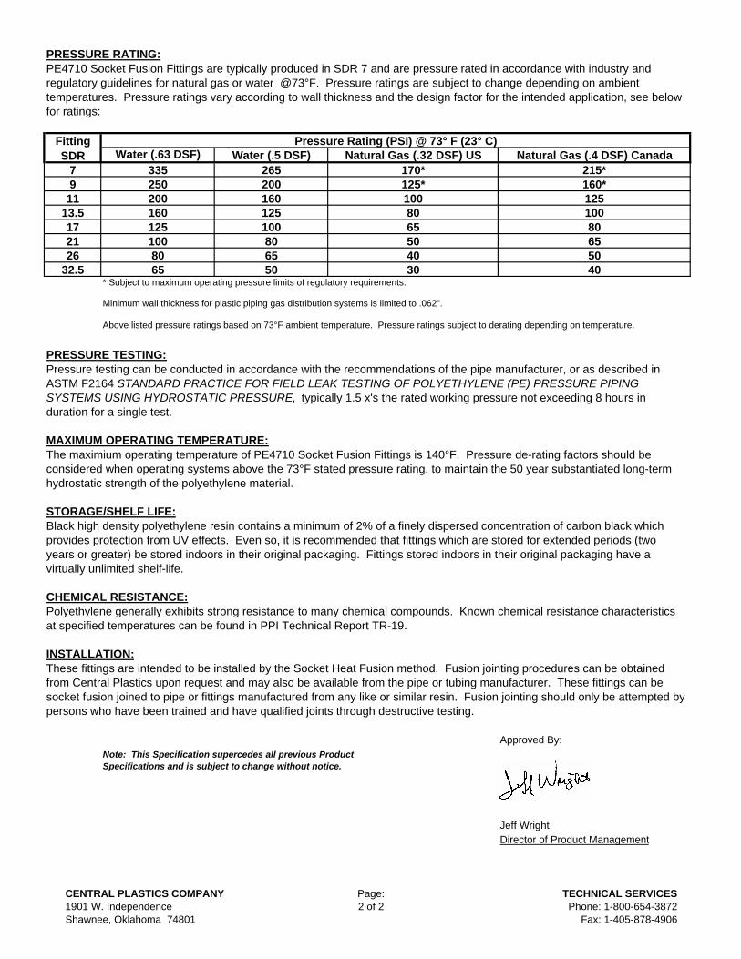
PRESSURE RATING:
79
1113.5172126
32.5* Subject to maximum operating pressure limits of regulatory requirements.
Minimum wall thickness for plastic piping gas distribution systems is limited to .062".
Above listed pressure ratings based on 73°F ambient temperature. Pressure ratings subject to derating depending on temperature.
PRESSURE TESTING:
MAXIMUM OPERATING TEMPERATURE:
STORAGE/SHELF LIFE:
CHEMICAL RESISTANCE:
INSTALLATION:
Approved By:
Jeff WrightDirector of Product Management
Pressure testing can be conducted in accordance with the recommendations of the pipe manufacturer, or as described in ASTM F2164 STANDARD PRACTICE FOR FIELD LEAK TESTING OF POLYETHYLENE (PE) PRESSURE PIPING SYSTEMS USING HYDROSTATIC PRESSURE, typically 1.5 x's the rated working pressure not exceeding 8 hours in duration for a single test.
Note: This Specification supercedes all previous Product Specifications and is subject to change without notice.
The maximium operating temperature of PE4710 Socket Fusion Fittings is 140°F. Pressure de-rating factors should be considered when operating systems above the 73°F stated pressure rating, to maintain the 50 year substantiated long-term hydrostatic strength of the polyethylene material.
Natural Gas (.4 DSF) Canada
80
Polyethylene generally exhibits strong resistance to many chemical compounds. Known chemical resistance characteristics at specified temperatures can be found in PPI Technical Report TR-19.
100125
Water (.63 DSF)
PE4710 Socket Fusion Fittings are typically produced in SDR 7 and are pressure rated in accordance with industry and regulatory guidelines for natural gas or water @73°F. Pressure ratings are subject to change depending on ambient temperatures. Pressure ratings vary according to wall thickness and the design factor for the intended application, see below for ratings:
40
Water (.5 DSF) Natural Gas (.32 DSF) USFitting SDR
Pressure Rating (PSI) @ 73° F (23° C)
80
These fittings are intended to be installed by the Socket Heat Fusion method. Fusion jointing procedures can be obtained from Central Plastics upon request and may also be available from the pipe or tubing manufacturer. These fittings can be socket fusion joined to pipe or fittings manufactured from any like or similar resin. Fusion jointing should only be attempted by persons who have been trained and have qualified joints through destructive testing.
80655040
6550
6550
215*160*125
170*125*100
160125
335250
100
30
265
Black high density polyethylene resin contains a minimum of 2% of a finely dispersed concentration of carbon black which provides protection from UV effects. Even so, it is recommended that fittings which are stored for extended periods (two years or greater) be stored indoors in their original packaging. Fittings stored indoors in their original packaging have a virtually unlimited shelf-life.
8065
100
200160200
CENTRAL PLASTICS COMPANY1901 W. IndependenceShawnee, Oklahoma 74801
Page:2 of 2
TECHNICAL SERVICESPhone: 1-800-654-3872
Fax: 1-405-878-4906
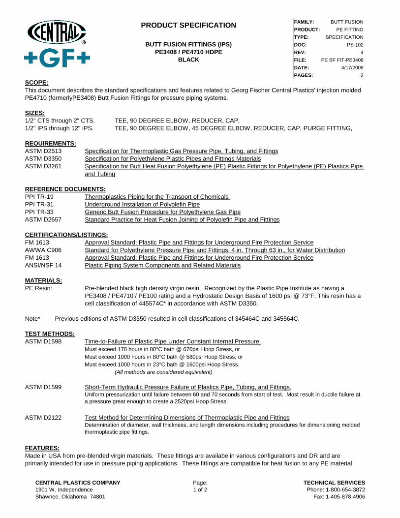
FAMILY: BUTT FUSIONPRODUCT: PE FITTINGTYPE: SPECIFICATIONDOC: PS-102REV: 4FILE: PE BF FIT-PE3408DATE: 4/17/2009PAGES: 2
SCOPE:
SIZES:
1/2" CTS through 2" CTS. TEE, 90 DEGREE ELBOW, REDUCER, CAP, 1/2" IPS through 12" IPS. TEE, 90 DEGREE ELBOW, 45 DEGREE ELBOW, REDUCER, CAP, PURGE FITTING,
REQUIREMENTS:
ASTM D2513 Specification for Thermoplastic Gas Pressure Pipe, Tubing, and FittingsASTM D3350 Specification for Polyethylene Plastic Pipes and Fittings MaterialsASTM D3261
REFERENCE DOCUMENTS:
PPI TR-19 Thermoplastics Piping for the Transport of Chemicals PPI TR-31 Underground Installation of Polyolefin PipePPI TR-33 Generic Butt Fusion Procedure for Polyethylene Gas PipeASTM D2657 Standard Practice for Heat Fusion Joining of Polyolefin Pipe and Fittings
CERTIFICATIONS/LISTINGS:
FM 1613 Approval Standard: Plastic Pipe and Fittings for Underground Fire Protection ServiceAWWA C906 Standard for Polyethylene Pressure Pipe and Fittings, 4 in. Through 63 in., for Water DistributionFM 1613 Approval Standard: Plastic Pipe and Fittings for Underground Fire Protection ServiceANSI/NSF 14 Plastic Piping System Components and Related Materials
MATERIALS:
PE Resin:
Note*
TEST METHODS:
ASTM D1598 Time-to-Failure of Plastic Pipe Under Constant Internal Pressure.Must exceed 170 hours in 80°C bath @ 670psi Hoop Stress, orMust exceed 1000 hours in 80°C bath @ 580psi Hoop Stress, orMust exceed 1000 hours in 23°C bath @ 1600psi Hoop Stress.
(All methods are considered equivalent)
ASTM D1599 Short-Term Hydraulic Pressure Failure of Plastics Pipe, Tubing, and Fittings.
ASTM D2122 Test Method for Determining Dimensions of Thermoplastic Pipe and Fittings
FEATURES:
Uniform pressurization until failure between 60 and 70 seconds from start of test. Most result in ductile failure at a pressure great enough to create a 2520psi Hoop Stress.
Determination of diameter, wall thickness, and length dimensions including procedures for dimensioning molded thermoplastic pipe fittings.
PRODUCT SPECIFICATION
BUTT FUSION FITTINGS (IPS)
PE3408 / PE4710 HDPE
BLACK
Previous editions of ASTM D3350 resulted in cell classifications of 345464C and 345564C.
This document describes the standard specifications and features related to Georg Fischer Central Plastics' injection molded PE4710 (formerlyPE3408) Butt Fusion Fittings for pressure piping systems.
Specification for Butt Heat Fusion Polyethylene (PE) Plastic Fittings for Polyethylene (PE) Plastics Pipe and Tubing
Pre-blended black high density virgin resin. Recognized by the Plastic Pipe Institute as having a PE3408 / PE4710 / PE100 rating and a Hydrostatic Design Basis of 1600 psi @ 73°F. This resin has a cell classification of 445574C* in accordance with ASTM D3350.
Made in USA from pre-blended virgin materials. These fittings are availabe in various configurations and DR and are primarily intended for use in pressure piping applications. These fittings are compatible for heat fusion to any PE material
CENTRAL PLASTICS COMPANY
1901 W. IndependenceShawnee, Oklahoma 74801
Page:1 of 2
TECHNICAL SERVICES
Phone: 1-800-654-3872Fax: 1-405-878-4906

PRESSURE RATING:
7
9
11
13.5
17
21
26
32.5* Subject to maximum operating pressure limits of regulatory requirements.
Minimum wall thickness for plastic piping gas distribution systems is limited to .062".
Above listed pressure ratings based on 73°F ambient temperature. Pressure ratings subject to derating depending on temperature.
PRESSURE TESTING:
MAXIMUM OPERATING TEMPERATURE:
STORAGE/SHELF LIFE:
CHEMICAL RESISTANCE:
INSTALLATION:
Approved By:
Jeff WrightDirector of Product Management
Pressure testing can be conducted in accordance with the recommendations of the pipe manufacturer, or as described in ASTM F2164 STANDARD PRACTICE FOR FIELD LEAK TESTING OF POLYETHYLENE (PE) PRESSURE PIPING SYSTEMS USING HYDROSTATIC PRESSURE, typically 1.5 x's the rated working pressure not exceeding 8 hours in duration for a single test.
Note: This Specification supercedes all previous Product Specifications and is subject to change without notice.
The maximium operating temperature of PE4710 Butt Fusion Fittings is 140°F. Pressure de-rating factors should be considered when operating systems above the 73°F stated pressure rating, to maintain the 50 year substantiated long-term hydrostatic strength of the polyethylene material.
Natural Gas (.4 DSF) Canada
80
Polyethylene generally exhibits strong resistance to many chemical compounds. Known chemical resistance characteristics at specified temperatures can be found in PPI Technical Report TR-19.
100
125
Water (.63 DSF)
40
PE4710 Butt Fusion Fittings are pressure rated in accordance with industry and regulatory guidelines for natural gas or water @73°F. Pressure ratings are subject to change depending on ambient temperatures. Pressure ratings vary according to wall thickness and the design factor for the intended application, see below for ratings:
Water (.5 DSF) Natural Gas (.32 DSF) US
made from a like or similar resin. Select sizes can be supplied with AWWA or FM marking. Designed for use on pipe conforming to ASTM F714, D2513, and D3035.
Fitting
SDR
Pressure Rating (PSI) @ 73° F (23° C)
80
These fittings are compatible for heat fusion by butt, socket, or electrofusion joining products. They can be heat fusion joined to pipe or fittings manufactured from like or similar resin. Qualified mechanical joining products can be used to join these fittings, consult the manufacturer for recommendations. Fusion jointing should only be attempted by persons who have been trained and have qualified joints through destructive testing.
80
65
50
40
65
50
65
50
215*
160*
125
170*
125*
100
160
125
335
250
100
30
265
Black high density polyethylene resin contains a minimum of 2% of a finely dispersed concentration of carbon black which provides protection from UV effects. Even so, it is recommended that fittings which are stored for extended periods (two years or greater) be stored indoors in their original packaging. Fittings stored indoors in their original packaging have a virtually unlimited shelf-life.
80
65
100
200
160200
CENTRAL PLASTICS COMPANY
1901 W. IndependenceShawnee, Oklahoma 74801
Page:2 of 2
TECHNICAL SERVICES
Phone: 1-800-654-3872Fax: 1-405-878-4906

PRODUCT SPECIFICATION FAMILY: BUTT FUSIONPRODUCT: PE FATYPE: SPECIFICATION
BUTT FUSION FLANGE ADPATER DOC: PS-104PE3408/PE4710/PE100 HDPE REV: 2
BLACK FILE: PE BF FA-PE3408-PE4710
DATE: 8/23/2006PAGES: 2
SCOPE:This document describes the standard specifications and features related to Central Plastics' IPS and DIPS sized PE4710 Butt Fusion Flange Adapter for pressure piping systems.
SIZES:2" IPS through 24" IPS4" DIPS through 24" DIPS.
REQUIREMENTS:ASTM D2513 Specification for Thermoplastic Gas Pressure Pipe, Tubing, and FittingsASTM D3350 Specification for Polyethylene Plastic Pipes and Fittings MaterialsASTM D3261 Specification for Butt Heat Fusion Polyethylene (PE) Plastic Fittings for Polyethylene (PE) Plastics Pipe
and Tubing
REFERENCE DOCUMENTS:PPI TR-19 Thermoplastics Piping for the Transport of Chemicals PPI TR-31 Underground Installation of Polyolefin PipePPI TR-33 Generic Butt Fusion Procedure for Polyethylene Gas PipeASTM D2657 Standard Practice for Heat Fusion Joining of Polyolefin Pipe and FittingsASTM F714 Standard Specification for Polyethylene (PE) Plastic Pipe Based on Outside Diameter
CERTIFICATIONS/LISTINGS:FM 1613 Approval Standard: Plastic Pipe and Fittings for Underground Fire Protection ServiceAWWA C906 Standard for Polyethylene Pressure Pipe and Fittings, 4 in. Through 63 in., for Water Distribution
MATERIALS:PE Resin: Pre-blended black high density virgin resin. Recognized by the Plastic Pipe Institute as having a
PE3408 / PE4710 / PE100 rating and a Hydrostatic Design Basis of 1600 psi @ 73°F. This resin has a cell classification of 445574C* in accordance with ASTM D3350.
Note* Previous editions of ASTM D3350 resulted in cell classifications of 345464C and 345564C.
TEST METHODS:ASTM D1598 Time-to-Failure of Plastic Pipe Under Constant Internal Pressure.
Must exceed 170 hours in 80°C bath @ 670psi Hoop Stress, orMust exceed 1000 hours in 80°C bath @ 580psi Hoop Stress, orMust exceed 1000 hours in 23°C bath @ 1600psi Hoop Stress.
(All methods are considered equivalent)
ASTM D1599 Short-Term Hydraulic Pressure Failure of Plastics Pipe, Tubing, and Fittings.Uniform pressurization until failure between 60 and 70 seconds from start of test. Must result in ductile failure at a pressure great enough to create a 2520psi Hoop Stress.
ASTM D2122 Test Method for Determining Dimensions of Thermoplastic Pipe and FittingsDetermination of diameter, wall thickness, and length dimensions including procedures for dimensioning molded thermoplastic pipe fittings.
CENTRAL PLASTICS COMPANY1901 W. IndependenceShawnee, Oklahoma 74801
Page:1 of 2
TECHNICAL SERVICESPhone: 1-800-654-3872
Fax: 1-405-878-4906
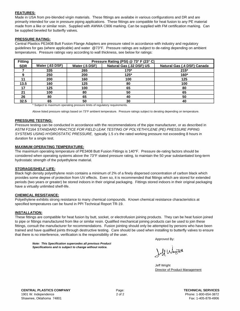
FEATURES:Made in USA from pre-blended virgin materials. These fittings are availabe in various configurations and DR and are primarily intended for use in pressure piping applications. These fittings are compatible for heat fusion to any PE material made from a like or similar resin. Supplied with AWWA C906 marking. Can be supplied with FM certification marking. Can be supplied beveled for butterfly valves.
PRESSURE RATING:Central Plastics PE3408 Butt Fusion Flange Adapters are pressure rated in accordance with industry and regulatory guidelines for gas (where applicable) and water @73°F. Pressure ratings are subject to de-rating depending on ambient temperatures. Pressure ratings vary according to wall thickness, see below for ratings:
Fitting SDR
Pressure Rating (PSI) @ 73° F (23° C)Water (.63 DSF) Water (.5 DSF) Natural Gas (.32 DSF) US Natural Gas (.4 DSF) Canada
7 335 265 170* 215*9 250 200 125* 160*11 200 160 100 125
13.5 160 125 80 10017 125 100 65 8021 100 80 50 6526 80 65 40 50
32.5 65 50 30 40* Subject to maximum operating pressure limits of regulatory requirements.
Above listed pressure ratings based on 73°F ambient temperature. Pressure ratings subject to derating depending on temperature.
PRESSURE TESTING:Pressure testing can be conducted in accordance with the recommendations of the pipe manufacturer, or as described in ASTM F2164 STANDARD PRACTICE FOR FIELD LEAK TESTING OF POLYETHYLENE (PE) PRESSURE PIPING SYSTEMS USING HYDROSTATIC PRESSURE, typically 1.5 x's the rated working pressure not exceeding 8 hours in duration for a single test.
MAXIMUM OPERATING TEMPERATURE:The maximium operating temperature of PE3408 Butt Fusion Fittings is 140°F. Pressure de-rating factors should be considered when operating systems above the 73°F stated pressure rating, to maintain the 50 year substantiated long-term hydrostatic strength of the polyethylene material.
STORAGE/SHELF LIFE:Black high density polyethylene resin contains a minimum of 2% of a finely dispersed concentration of carbon black which provides some degree of protection from UV effects. Even so, it is recommended that fittings which are stored for extended periods (two years or greater) be stored indoors in their original packaging. Fittings stored indoors in their original packaging have a virtually unlimited shelf-life.
CHEMICAL RESISTANCE:Polyethylene exhibits strong resistance to many chemical compounds. Known chemical resistance characteristics at specified temperatures can be found in PPI Technical Report TR-19.
INSTALLATION:These fittings are compatible for heat fusion by butt, socket, or electrofusion joining products. They can be heat fusion joined to pipe or fittings manufactured from like or similar resin. Qualified mechanical joining products can be used to join these fittings, consult the manufacturer for recommendations. Fusion jointing should only be attempted by persons who have been trained and have qualified joints through destructive testing. Care should be used when installing to butterfly valves to ensure that there is no interference, verification is the responsibility of the user.
Approved By:Note: This Specification supercedes all previous Product Specifications and is subject to change without notice.
Jeff WrightDirector of Product Management
CENTRAL PLASTICS COMPANY1901 W. IndependenceShawnee, Oklahoma 74801
Page:2 of 2
TECHNICAL SERVICESPhone: 1-800-654-3872
Fax: 1-405-878-4906

FAMILY: BUTT FUSIONPRODUCT: PE MJ AdapterTYPE: SPECIFICATIONDOC: PS-105REV: 2FILE: PE BF MJ-PE3408DATE: 8/30/2006PAGES: 2
SCOPE:
SIZES:3" IPS through 24" IPS3" DIPS through 24" DIPS.
REQUIREMENTS:ASTM D3350 Specification for Polyethylene Plastic Pipes and Fittings MaterialsASTM D3261
REFERENCE DOCUMENTS:PPI TR-19 Thermoplastics Piping for the Transport of Chemicals PPI TR-31 Underground Installation of Polyolefin PipePPI TR-33 Generic Butt Fusion Procedure for Polyethylene Gas PipeASTM D2657 Standard Practice for Heat Fusion Joining of Polyolefin Pipe and FittingsASTM F714 Standard Specification for Polyethylene (PE) Plastic Pipe Based on Outside Diameter
CERTIFICATIONS/LISTINGS:FM 1613 Approval Standard: Plastic Pipe and Fittings for Underground Fire Protection ServiceAWWA C906 Standard for Polyethylene Pressure Pipe and Fittings, 4 in. Through 63 in., for Water Distribution
MATERIALS:PE Resin:
Note*
TEST METHODS:ASTM D1598 Time-to-Failure of Plastic Pipe Under Constant Internal Pressure.
Must exceed 170 hours in 80°C bath @ 670psi Hoop Stress, orMust exceed 1000 hours in 80°C bath @ 580psi Hoop Stress, orMust exceed 1000 hours in 23°C bath @ 1600psi Hoop Stress.
(All methods are considered equivalent)
ASTM D1599 Short-Term Hydraulic Pressure Failure of Plastics Pipe, Tubing, and Fittings.
ASTM D2122 Test Method for Determining Dimensions of Thermoplastic Pipe and Fittings
FEATURES:
This document describes the standard specifications and features related to Central Plastics' IPS and DIPS sized PE3408 Butt Fusion Mechanical Joint (MJ) Adapter for pressure piping systems.
Specification for Butt Heat Fusion Polyethylene (PE) Plastic Fittings for Polyethylene (PE) Plastics Pipe and Tubing
Pre-blended black high density virgin resin. Recognized by the Plastic Pipe Institute as having a PE3408 / PE4710 / PE100 rating and a Hydrostatic Design Basis of 1600 psi @ 73 °F. This resin has a cell classification of 445574C* in accordance with ASTM D3350. NSF Listed.
Previous editions of ASTM D3350 resulted in cell classifications of 345464C and 345564C.
Made in USA from pre-blended virgin materials. These fittings are availabe in various configurations and DR and are primarily intended for use in pressure piping applications. These fittings are compatible for heat fusion to any PE material made from a like or similar resin. Supplied with AWWA C906 marking. Can be supplied with FM certification marking. Can be supplied beveled for butterfly valves. Can be supplied with accessory kit including gasket, ring, and special length bolts.
PRODUCT SPECIFICATION
BUTT FUSION MECHANCIAL JOINT (MJ) ADAPTERPE3408/PE4710/PE100 HDPE
BLACK
Uniform pressurization until failure between 60 and 70 seconds from start of test. Must result in ductile failure at a pressure great enough to create a 2520psi Hoop Stress.
Determination of diameter, wall thickness, and length dimensions including procedures for dimensioning molded thermoplastic pipe fittings.
CENTRAL PLASTICS COMPANY1901 W. IndependenceShawnee, Oklahoma 74801
Page:1 of 2
TECHNICAL SERVICESPhone: 1-800-654-3872
Fax: 1-405-878-4906
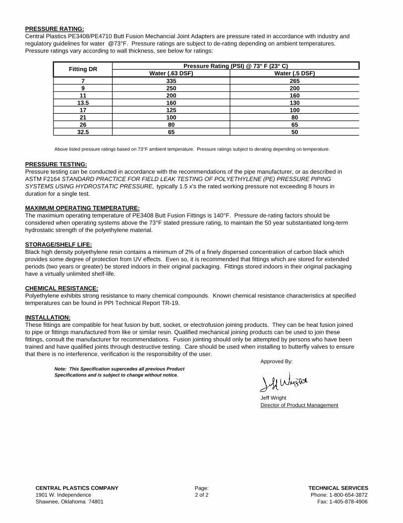
PRESSURE RATING:
Above listed pressure ratings based on 73°F ambient temperature. Pressure ratings subject to derating depending on temperature.
PRESSURE TESTING:
MAXIMUM OPERATING TEMPERATURE:
STORAGE/SHELF LIFE:
CHEMICAL RESISTANCE:
INSTALLATION:
Approved By:
Jeff WrightDirector of Product Management
8065
200160
250200
Pressure testing can be conducted in accordance with the recommendations of the pipe manufacturer, or as described in ASTM F2164 STANDARD PRACTICE FOR FIELD LEAK TESTING OF POLYETHYLENE (PE) PRESSURE PIPING SYSTEMS USING HYDROSTATIC PRESSURE, typically 1.5 x's the rated working pressure not exceeding 8 hours in duration for a single test.
50
1301008065
125100
160
21
7Water (.63 DSF)
335Water (.5 DSF)
265
Fitting DR
1113.517
Central Plastics PE3408/PE4710 Butt Fusion Mechancial Joint Adapters are pressure rated in accordance with industry and regulatory guidelines for water @73°F. Pressure ratings are subject to de-rating depending on ambient temperatures. Pressure ratings vary according to wall thickness, see below for ratings:
Pressure Rating (PSI) @ 73° F (23° C)
Note: This Specification supercedes all previous Product Specifications and is subject to change without notice.
The maximium operating temperature of PE3408 Butt Fusion Fittings is 140°F. Pressure de-rating factors should be considered when operating systems above the 73°F stated pressure rating, to maintain the 50 year substantiated long-term hydrostatic strength of the polyethylene material.
Polyethylene exhibits strong resistance to many chemical compounds. Known chemical resistance characteristics at specified temperatures can be found in PPI Technical Report TR-19.
9
These fittings are compatible for heat fusion by butt, socket, or electrofusion joining products. They can be heat fusion joined to pipe or fittings manufactured from like or similar resin. Qualified mechanical joining products can be used to join these fittings, consult the manufacturer for recommendations. Fusion jointing should only be attempted by persons who have been trained and have qualified joints through destructive testing. Care should be used when installing to butterfly valves to ensure that there is no interference, verification is the responsibility of the user.
Black high density polyethylene resin contains a minimum of 2% of a finely dispersed concentration of carbon black which provides some degree of protection from UV effects. Even so, it is recommended that fittings which are stored for extended periods (two years or greater) be stored indoors in their original packaging. Fittings stored indoors in their original packaging have a virtually unlimited shelf-life.
2632.5
CENTRAL PLASTICS COMPANY1901 W. IndependenceShawnee, Oklahoma 74801
Page:2 of 2
TECHNICAL SERVICESPhone: 1-800-654-3872
Fax: 1-405-878-4906
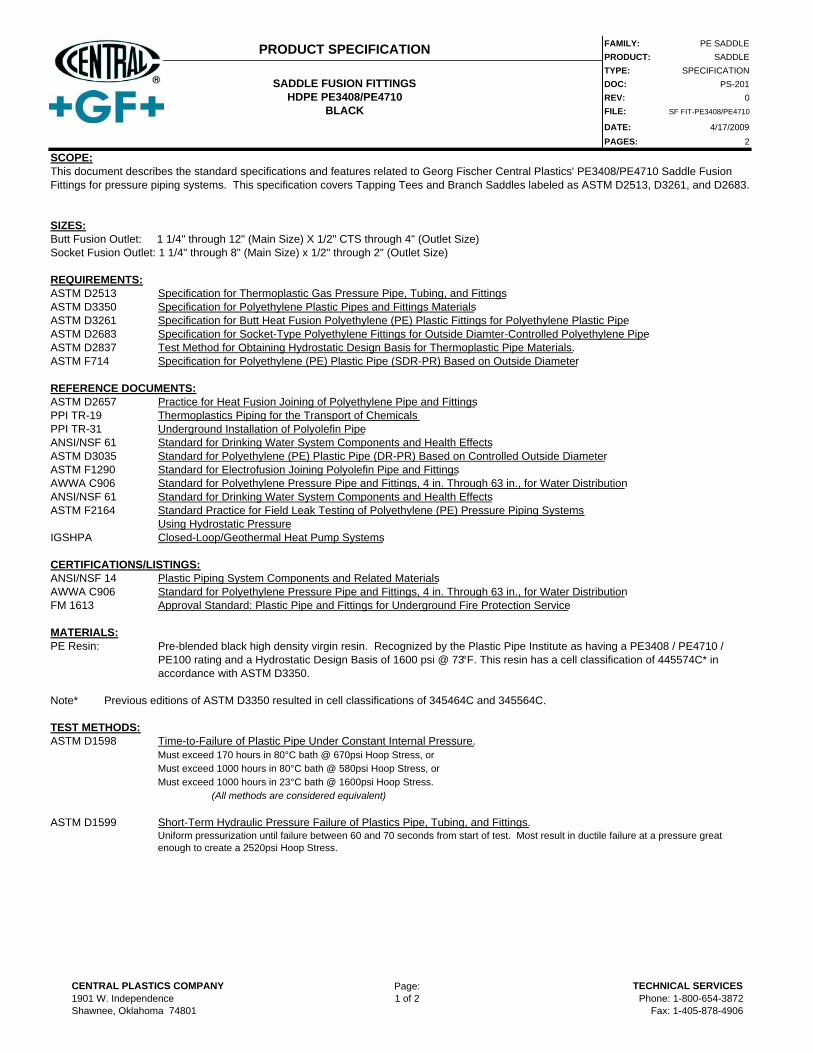
FAMILY: PE SADDLEPRODUCT: SADDLETYPE: SPECIFICATIONDOC: PS-201REV: 0FILE: SF FIT-PE3408/PE4710
DATE: 4/17/2009PAGES: 2
SCOPE:
SIZES:Butt Fusion Outlet: 1 1/4" through 12" (Main Size) X 1/2" CTS through 4" (Outlet Size)Socket Fusion Outlet: 1 1/4" through 8" (Main Size) x 1/2" through 2" (Outlet Size)
REQUIREMENTS:ASTM D2513 Specification for Thermoplastic Gas Pressure Pipe, Tubing, and FittingsASTM D3350 Specification for Polyethylene Plastic Pipes and Fittings MaterialsASTM D3261 Specification for Butt Heat Fusion Polyethylene (PE) Plastic Fittings for Polyethylene Plastic PipeASTM D2683 Specification for Socket-Type Polyethylene Fittings for Outside Diamter-Controlled Polyethylene PipeASTM D2837 Test Method for Obtaining Hydrostatic Design Basis for Thermoplastic Pipe Materials.ASTM F714 Specification for Polyethylene (PE) Plastic Pipe (SDR-PR) Based on Outside Diameter
REFERENCE DOCUMENTS:ASTM D2657 Practice for Heat Fusion Joining of Polyethylene Pipe and FittingsPPI TR-19 Thermoplastics Piping for the Transport of Chemicals PPI TR-31 Underground Installation of Polyolefin PipeANSI/NSF 61 Standard for Drinking Water System Components and Health EffectsASTM D3035 Standard for Polyethylene (PE) Plastic Pipe (DR-PR) Based on Controlled Outside DiameterASTM F1290 Standard for Electrofusion Joining Polyolefin Pipe and FittingsAWWA C906 Standard for Polyethylene Pressure Pipe and Fittings, 4 in. Through 63 in., for Water DistributionANSI/NSF 61 Standard for Drinking Water System Components and Health EffectsASTM F2164 Standard Practice for Field Leak Testing of Polyethylene (PE) Pressure Piping Systems
Using Hydrostatic PressureIGSHPA Closed-Loop/Geothermal Heat Pump Systems
CERTIFICATIONS/LISTINGS:ANSI/NSF 14 Plastic Piping System Components and Related MaterialsAWWA C906 Standard for Polyethylene Pressure Pipe and Fittings, 4 in. Through 63 in., for Water DistributionFM 1613 Approval Standard: Plastic Pipe and Fittings for Underground Fire Protection Service
MATERIALS:PE Resin:
Note*
TEST METHODS:ASTM D1598 Time-to-Failure of Plastic Pipe Under Constant Internal Pressure.
Must exceed 170 hours in 80°C bath @ 670psi Hoop Stress, orMust exceed 1000 hours in 80°C bath @ 580psi Hoop Stress, orMust exceed 1000 hours in 23°C bath @ 1600psi Hoop Stress.
(All methods are considered equivalent)
ASTM D1599 Short-Term Hydraulic Pressure Failure of Plastics Pipe, Tubing, and Fittings.
PRODUCT SPECIFICATION
SADDLE FUSION FITTINGSHDPE PE3408/PE4710
BLACK
This document describes the standard specifications and features related to Georg Fischer Central Plastics' PE3408/PE4710 Saddle Fusion Fittings for pressure piping systems. This specification covers Tapping Tees and Branch Saddles labeled as ASTM D2513, D3261, and D2683.
Uniform pressurization until failure between 60 and 70 seconds from start of test. Most result in ductile failure at a pressure great enough to create a 2520psi Hoop Stress.
Pre-blended black high density virgin resin. Recognized by the Plastic Pipe Institute as having a PE3408 / PE4710 / PE100 rating and a Hydrostatic Design Basis of 1600 psi @ 73°F. This resin has a cell classification of 445574C* in accordance with ASTM D3350.
Previous editions of ASTM D3350 resulted in cell classifications of 345464C and 345564C.
CENTRAL PLASTICS COMPANY1901 W. IndependenceShawnee, Oklahoma 74801
Page:1 of 2
TECHNICAL SERVICESPhone: 1-800-654-3872
Fax: 1-405-878-4906
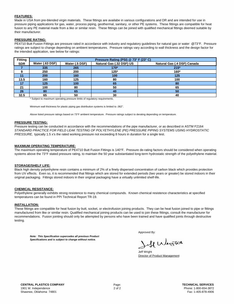
FEATURES:
PRESSURE RATING:
7911
13.5172126
32.5* Subject to maximum operating pressure limits of regulatory requirements.
Minimum wall thickness for plastic piping gas distribution systems is limited to .062".
Above listed pressure ratings based on 73°F ambient temperature. Pressure ratings subject to derating depending on temperature.
PRESSURE TESTING:
MAXIMUM OPERATING TEMPERATURE:
STORAGE/SHELF LIFE:
CHEMICAL RESISTANCE:
INSTALLATION:
Approved By:
Jeff WrightDirector of Product Management
These fittings are compatible for heat fusion by butt, socket, or electrofusion joining products. They can be heat fusion joined to pipe or fittings manufactured from like or similar resin. Qualified mechanical joining products can be used to join these fittings, consult the manufacturer for recommendations. Fusion jointing should only be attempted by persons who have been trained and have qualified joints through destructive testing.
Note: This Specification supercedes all previous Product Specifications and is subject to change without notice.
The maximium operating temperature of PE4710 Butt Fusion Fittings is 140°F. Pressure de-rating factors should be considered when operating systems above the 73°F stated pressure rating, to maintain the 50 year substantiated long-term hydrostatic strength of the polyethylene material.
Polyethylene generally exhibits strong resistence to many chemical compounds. Known chemical resistence characteristics at specified temperatures can be found in PPI Technical Report TR-19.
Black high density polyethylene resin contains a minimum of 2% of a finely dispersed concentration of carbon black which provides protection from UV effects. Even so, it is recommended that fittings which are stored for extended periods (two years or greater) be stored indoors in their original packaging. Fittings stored indoors in their original packaging have a virtually unlimited shelf-life.
Made in USA from pre-blended virgin materials. These fittings are availabe in various configurations and DR and are intended for use in pressure piping applications for gas, water, process piping, geothermal, sanitary, or other PE systems. These fittings are compatible for heat fusion to any PE material made from a like or similar resin. These fittings can be joined with qualified mechanical fittings deemed suitable by their manufacturer.
Pressure testing can be conducted in accordance with the recommendations of the pipe manufacturer, or as described in ASTM F2164 STANDARD PRACTICE FOR FIELD LEAK TESTING OF POLYETHYLENE (PE) PRESSURE PIPING SYSTEMS USING HYDROSTATIC PRESSURE, typically 1.5 x's the rated working pressure not exceeding 8 hours in duration for a single test.
PE4710 Butt Fusion Fittings are pressure rated in accordance with industry and regulatory guidelines for natural gas or water @73°F. Pressure ratings are subject to change depending on ambient temperatures. Pressure ratings vary according to wall thickness and the design factor for the intended application, see below for ratings:
Fitting SDR
Pressure Rating (PSI) @ 73° F (23° C)Water (.63 DSF) Water (.5 DSF) Natural Gas (.32 DSF) US Natural Gas (.4 DSF) Canada
335 265 170* 215*250 200 125* 160*200 160 100 125160 125 80 100125 100 65 80100 80 50 6580 65 40 5065 50 30 40
CENTRAL PLASTICS COMPANY1901 W. IndependenceShawnee, Oklahoma 74801
Page:2 of 2
TECHNICAL SERVICESPhone: 1-800-654-3872
Fax: 1-405-878-4906
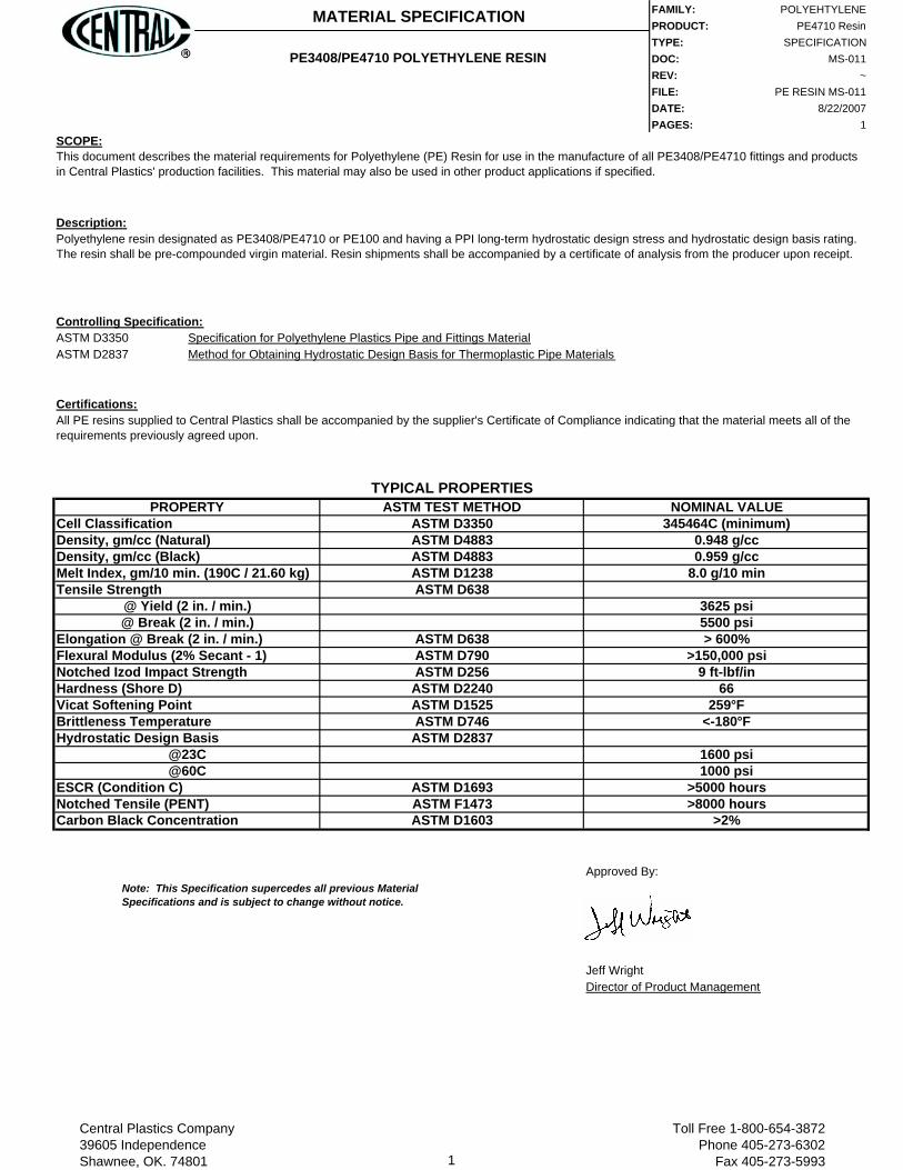
FAMILY: POLYEHTYLENEPRODUCT: PE4710 ResinTYPE: SPECIFICATIONDOC: MS-011REV: ~FILE: PE RESIN MS-011DATE: 8/22/2007PAGES: 1
SCOPE:
Description:
Controlling Specification:ASTM D3350 Specification for Polyethylene Plastics Pipe and Fittings MaterialASTM D2837 Method for Obtaining Hydrostatic Design Basis for Thermoplastic Pipe Materials
Certifications:
Approved By:
Jeff WrightDirector of Product Management
>2%
TYPICAL PROPERTIES
>5000 hours>8000 hours
<-180°F
1600 psi1000 psi
>150,000 psi9 ft-lbf/in
66259°F
345464C (minimum)0.948 g/cc0.959 g/cc
8.0 g/10 min
3625 psi5500 psi> 600%
ASTM D1693ASTM F1473ASTM D1603
ASTM D2837
ASTM D256ASTM D2240ASTM D1525ASTM D746
ASTM D3350ASTM D4883ASTM D4883ASTM D1238ASTM D638
ASTM D638ASTM D790
Carbon Black Concentration
@23C@60C
ESCR (Condition C)
Vicat Softening PointBrittleness TemperatureHydrostatic Design Basis
Notched Tensile (PENT)
Elongation @ Break (2 in. / min.)Flexural Modulus (2% Secant - 1)Notched Izod Impact StrengthHardness (Shore D)
Melt Index, gm/10 min. (190C / 21.60 kg)Tensile Strength
@ Yield (2 in. / min.)@ Break (2 in. / min.)
NOMINAL VALUECell ClassificationDensity, gm/cc (Natural)Density, gm/cc (Black)
Note: This Specification supercedes all previous Material Specifications and is subject to change without notice.
This document describes the material requirements for Polyethylene (PE) Resin for use in the manufacture of all PE3408/PE4710 fittings and products in Central Plastics' production facilities. This material may also be used in other product applications if specified.
MATERIAL SPECIFICATION
PE3408/PE4710 POLYETHYLENE RESIN
Polyethylene resin designated as PE3408/PE4710 or PE100 and having a PPI long-term hydrostatic design stress and hydrostatic design basis rating. The resin shall be pre-compounded virgin material. Resin shipments shall be accompanied by a certificate of analysis from the producer upon receipt.
All PE resins supplied to Central Plastics shall be accompanied by the supplier's Certificate of Compliance indicating that the material meets all of the requirements previously agreed upon.
PROPERTY ASTM TEST METHOD
Central Plastics Company39605 IndependenceShawnee, OK. 74801 1
Toll Free 1-800-654-3872Phone 405-273-6302
Fax 405-273-5993

RED-WHITE VALVE 20600 Regency Lane • Lake Forest, CA 92630 tel: 949.859.1010 • fax: 949.859.7200 • www.redwhitevalveusa.com
Materials & Specifications
Dimensions, Weights (inches-lbs.) & Valve Data
Figure # 938Ductile Iron Lug Style Butterfly Valve
Item Description Material1 Body Ductile Iron2 Disc Alum. Bronze, Ductile Iron or 316 SS.3 Seat Buna or EPDM4 Stem 416 or 316 Stainless Steel5 Bushings PTFE6 O-Ring NBR7 Taper Pin Stainless Steel8 Seat Support Plastic
Product Features• 200 PSI Sizes 2”-12”• 150 PSI Sizes 14” - UP• Ductile Iron Body• Lug Style Body• Cartridge Seat• ISO 5211 Mounting Flange• MSS-SP-67
Page 1 of 2
Size 2” 2-1/2” 3” 4” 5” 6” 8” 10” 12” 14” 16” 18” 20” 24”HA 2.99 3.5 3.74 4.49 5.0 5.51 6.81 7.99 9.33 10.98 11.97 14.25 14.49 17.48
HB 6.38 6.89 7.13 7.87 8.39 8.86 10.24 11.5 13.27 14.49 15.75 16.61 18.86 22.13
HC 1.26 1.26 1.26 1.26 1.26 1.26 1.77 1.77 1.77 1.77 2.01 2.01 2.52 2.8
L 1.69 1.81 1.81 2.05 2.2 2.2 2.36 2.68 3.07 3.07 4.02 4.49 5.0 6.0OK 4.75 5.5 6.0 7.5 8.5 9.5 11.75 14.25 17.0 18.75 21.25 22.75 25.0 29.5OF 5/8-11 5/8-11 5/8-11 5/8-11 3/4-10 3/4-10 3/4-10 7/8-9 7/8-9 1”-8 1”-8 1-1/8-8 1-1/8-8 1-1/4-7
OA .5 .5 .5 .63 .75 .75 .87 1.13 1.25 1.25 1.31 1.5 1.62 1.99
N # holes 4 4 4 8 8 8 8 12 12 12 16 16 20 20
Wt. lever 9 10 16 28 30 33 53 76 109 - - - - -
Wt. Gear 25 26 32 44 46 49 72 95 128 178 255 290 494 708
Figure Number Breakdown (Example 938DNSL)Disc Matl. Seat Matl. Stem Matl. Topworks
B = Aluminum Bronze E = EPDM M = 316 SS. L = Lever
D = Ductile Iron w/ Nickel plating N = Buna N S = 416 SS. G = Gear
M = 316 Stainless Steel ------ ------ X = Bare Stem
PSI 2” 2-1/2” 3” 4” 5’ 6” 8” 10” 12” 14” 16” 18” 20” 24”
50 100 150 207 290 423 599 1060 1671 2568 2640 4260 6287 8360 15427
100 106 163 220 323 481 691 1183 1872 2795 3070 4880 7243 9180 16813
150 111 176 232 357 540 783 1307 2074 3023 3500 5500 8200 10000 18200
200 117 189 244 390 598 875 1430 2275 3250 - - - - -
Seating torques (inch/lbs.)
All torque values shown are for wet (water and other non-lubricating media) on-off service. Fordry services (dry gas, etc.) multiply values by 1.15. For lubed service (clean, non-abrasive lubri-cating media) multiply values by .85. These values do not include a safety factor. An appropriatesafety factor should be used when sizing any actuator.
Note: Ductile Iron Disc areelectroless Nickel plated
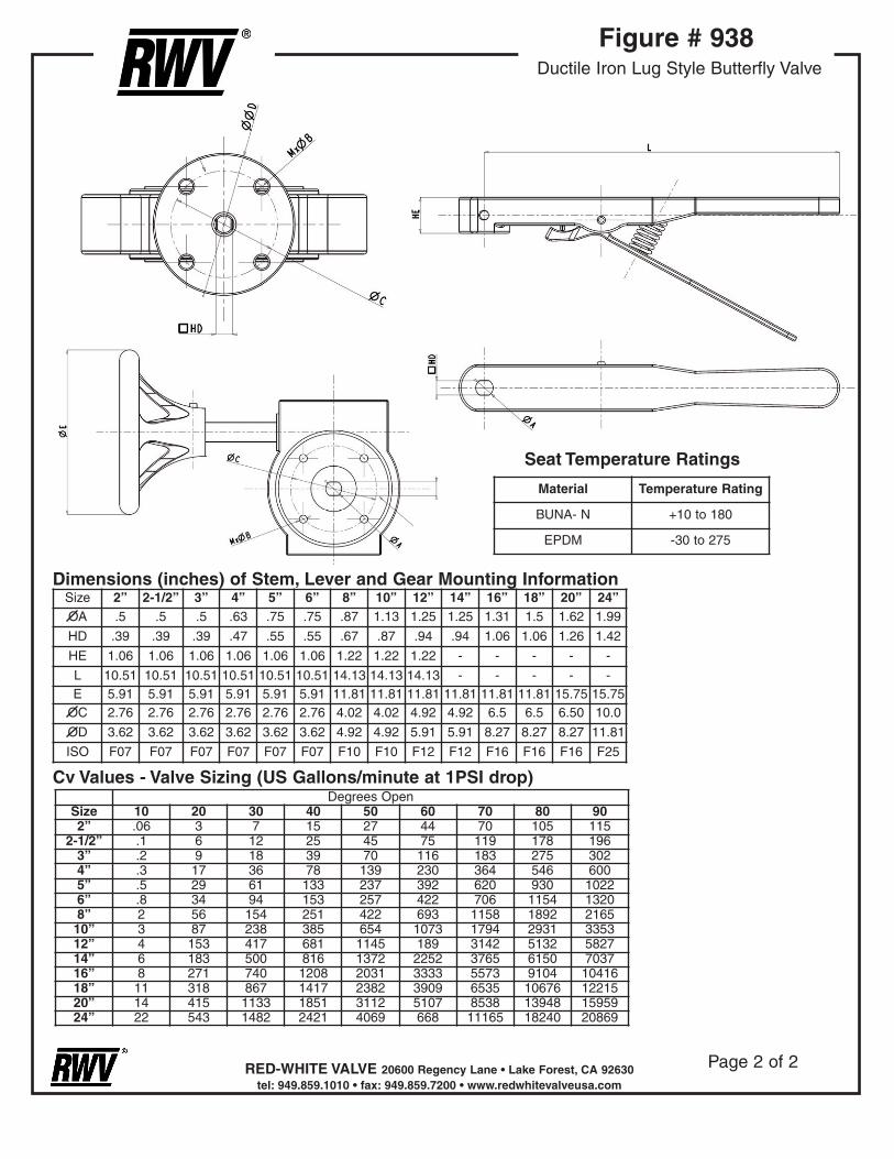
RED-WHITE VALVE 20600 Regency Lane • Lake Forest, CA 92630 tel: 949.859.1010 • fax: 949.859.7200 • www.redwhitevalveusa.com
Figure # 938Ductile Iron Lug Style Butterfly Valve
Page 2 of 2
Degrees OpenSize 10 20 30 40 50 60 70 80 902” .06 3 7 15 27 44 70 105 115
2-1/2” .1 6 12 25 45 75 119 178 1963” .2 9 18 39 70 116 183 275 3024” .3 17 36 78 139 230 364 546 6005” .5 29 61 133 237 392 620 930 10226” .8 34 94 153 257 422 706 1154 13208” 2 56 154 251 422 693 1158 1892 216510” 3 87 238 385 654 1073 1794 2931 335312” 4 153 417 681 1145 189 3142 5132 582714” 6 183 500 816 1372 2252 3765 6150 703716” 8 271 740 1208 2031 3333 5573 9104 1041618” 11 318 867 1417 2382 3909 6535 10676 1221520” 14 415 1133 1851 3112 5107 8538 13948 1595924” 22 543 1482 2421 4069 668 11165 18240 20869
Size 2” 2-1/2” 3” 4” 5” 6” 8” 10” 12” 14” 16” 18” 20” 24”OA .5 .5 .5 .63 .75 .75 .87 1.13 1.25 1.25 1.31 1.5 1.62 1.99
HD .39 .39 .39 .47 .55 .55 .67 .87 .94 .94 1.06 1.06 1.26 1.42
HE 1.06 1.06 1.06 1.06 1.06 1.06 1.22 1.22 1.22 - - - - -
L 10.51 10.51 10.51 10.51 10.51 10.51 14.13 14.13 14.13 - - - - -E 5.91 5.91 5.91 5.91 5.91 5.91 11.81 11.81 11.81 11.81 11.81 11.81 15.75 15.75
OC 2.76 2.76 2.76 2.76 2.76 2.76 4.02 4.02 4.92 4.92 6.5 6.5 6.50 10.0
OD 3.62 3.62 3.62 3.62 3.62 3.62 4.92 4.92 5.91 5.91 8.27 8.27 8.27 11.81
ISO F07 F07 F07 F07 F07 F07 F10 F10 F12 F12 F16 F16 F16 F25
Dimensions (inches) of Stem, Lever and Gear Mounting Information
Cv Values - Valve Sizing (US Gallons/minute at 1PSI drop)
Material Temperature Rating
BUNA- N +10 to 180
EPDM -30 to 275
Seat Temperature Ratings

RED-WHITE VALVE 20600 Regency Lane • Lake Forest, CA 92630 tel: 949.859.1010 • fax: 949.859.7200 • www.redwhitevalveusa.com
Materials & Specifications
Dimensions, Weights (inches-lbs.) & Valve Data
Figure # 937Ductile Iron Wafer Style Butterfly Valve
Item Description Material1 Body Ductile Iron2 Disc Alum. Bronze, Ductile Iron or 316 SS.3 Seat Buna or EPDM4 Stem 416 or 316 Stainless Steel5 Bushings PTFE6 O-Ring NBR7 Taper Pin Stainless Steel8 Seat Support Plastic
Product Features• 200 PSI Sizes 2”-12”• 150 PSI Sizes 14” - UP• Ductile Iron Body• Wafer Style Body• Cartridge Seat• ISO 5211 Mounting Flange• MSS-SP-67
Page 1 of 2
Size 2” 2-1/2” 3” 4” 5” 6” 8” 10” 12” 14” 16” 18” 20” 24”HA 2.99 3.5 3.74 4.49 5.0 5.51 6.81 7.99 9.57 10.5111.7312.5213.7416.14
HB 6.38 6.89 7.13 7.87 8.39 8.86 10.24 11.5 13.2714.4915.7516.6118.8622.13
HC 1.26 1.26 1.26 1.26 1.26 1.26 1.77 1.77 1.77 1.77 2.01 2.01 2.52 2.8
L 1.69 1.81 1.81 2.05 2.2 2.2 2.36 2.68 3.07 3.07 4.02 4.49 5.0 6.0OK 4.75 5.5 6.0 7.5 8.5 9.5 11.7514.25 17.0 18.7521.2522.75 25.0 29.5OF .75 .75 .75 .75 .88 .88 .88 1.0 1.0 1.12 1.12 1.25 1.25 1.38
OA .5 .5 .5 .63 .75 .75 .87 1.13 1.25 1.25 1.31 1.5 1.62 1.99
N 4 4 4 4 4 4 4 4 4 4 4 4 4 4
Wt. lever 8 9 12 15 20 22 36 46 74 - - - - -
Wt. Gear 24 25 28 31 36 38 55 65 93 118 177 225 373 538
Figure Number Breakdown (Example 937DNSL)Disc Matl. Seat Matl. Stem Matl. Topworks
B = Aluminum Bronze E = EPDM M = 316 SS. L = Lever
D = Ductile Iron w/ Nickel plating N = Buna N S = 416 SS. G = Gear
M = 316 Stainless Steel ------ ------ X = Bare Stem
PSI 2” 2-1/2” 3” 4” 5’ 6” 8” 10” 12” 14” 16” 18” 20” 24”
50 100 150 207 290 423 599 1060 1671 2568 2640 4260 6287 8360 15427
100 106 163 220 323 481 691 1183 1872 2795 3070 4880 7243 9180 16813
150 111 176 232 357 540 783 1307 2074 3023 3500 5500 8200 10000 18200
200 117 189 244 390 598 875 1430 2275 3250 - - - - -
Seating torques (inch/lbs.)
All torque values shown are for wet (water and other non-lubricating media) on-off service. Fordry services (dry gas, etc.) multiply values by 1.15. For lubed service (clean, non-abrasive lubri-cating media) multiply values by .85. These values do not include a safety factor. An appropriatesafety factor should be used when sizing any actuator.
Note: Ductile Iron Disc areelectroless Nickel plated

RED-WHITE VALVE 20600 Regency Lane • Lake Forest, CA 92630 tel: 949.859.1010 • fax: 949.859.7200 • www.redwhitevalveusa.com
Figure # 937Ductile Iron Wafer Style Butterfly Valve
Page 2 of 2
Degrees OpenSize 10 20 30 40 50 60 70 80 902” .06 3 7 15 27 44 70 105 115
2-1/2” .1 6 12 25 45 75 119 178 1963” .2 9 18 39 70 116 183 275 3024” .3 17 36 78 139 230 364 546 6005” .5 29 61 133 237 392 620 930 10226” .8 34 94 153 257 422 706 1154 13208” 2 56 154 251 422 693 1158 1892 216510” 3 87 238 385 654 1073 1794 2931 335312” 4 153 417 681 1145 189 3142 5132 582714” 6 183 500 816 1372 2252 3765 6150 703716” 8 271 740 1208 2031 3333 5573 9104 1041618” 11 318 867 1417 2382 3909 6535 10676 1221520” 14 415 1133 1851 3112 5107 8538 13948 1595924” 22 543 1482 2421 4069 668 11165 18240 20869
Size 2” 2-1/2” 3” 4” 5” 6” 8” 10” 12” 14” 16” 18” 20” 24”OA .5 .5 .5 .63 .75 .75 .87 1.13 1.25 1.25 1.31 1.5 1.62 1.99
HD .39 .39 .39 .47 .55 .55 .67 .87 .94 .94 1.06 1.06 1.26 1.42
HE 1.06 1.06 1.06 1.06 1.06 1.06 1.22 1.22 1.22 - - - - -
L 10.51 10.51 10.51 10.51 10.51 10.51 14.13 14.13 14.13 - - - - -E 5.91 5.91 5.91 5.91 5.91 5.91 11.81 11.81 11.81 11.81 11.81 11.81 15.75 15.75
OC 2.76 2.76 2.76 2.76 2.76 2.76 4.02 4.02 4.92 4.92 6.5 6.5 6.50 10.0
OD 3.62 3.62 3.62 3.62 3.62 3.62 4.92 4.92 5.91 5.91 8.27 8.27 8.27 11.81
ISO F07 F07 F07 F07 F07 F07 F10 F10 F12 F12 F16 F16 F16 F25
Dimensions (inches) of Stem, Lever and Gear Mounting Information
Cv Values - Valve Sizing (US Gallons/minute at 1PSI drop)
Material Temperature Rating
BUNA- N +10 to 180
EPDM -30 to 275
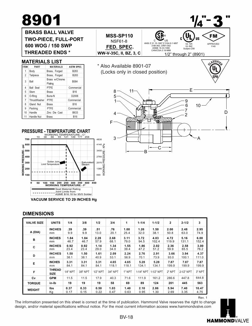
BRASS BALL VALVE
967
4
10
3
5
2
1
8 11
D
E
A
F
8901 14-"/ 3 "
RC US
UL 842UL 125
Subject 258
ANSI Z 21.15-1997 Z CGA 9.1-M973-88 IAS, CR91-002ASME 16.33-1990
CAN/CGA-3.16-M88
R
690
1380
2070
2760
4140
3450
4830
WO
RK
ING
PR
ES
SU
RE
-p
si
WORKING TEMPERATURE - F�
PRESSURE - TEMPERATURE CHART
100
200
300
400
600
500
700
0 50 150 200 250 300 350 400 450100
WO
RK
ING
PR
ES
SU
RE
-K
Pa
10WORKING TEMPERATURE - C�
66 121 149 177 20438 93
APPROVED1140
CB
1/2” through 2” (8901)
Solder JointLimit Temperature
SaturatedSteam
INCHES 1.50 1.50 1.61 2.09 2.24 2.76 2.91 3.66 3.94 4.37
mm 38.1 38.1 40.9 53.1 56.9 70.1 73.9 93.0 100.1 111.0
INCHES 3.31 3.31 3.31 4.65 4.65 5.28 5.28 7.87 7.87 7.87
mm 84.1 84.1 84.1 118.1 118.1 134.1 134.1 199.9 199.9 199.9
THREAD
SIZE1/4" NPT 3/8" NPT 1/2" NPT 3/4" NPT 1" NPT 1-1/4" NPT 1-1/2" NPT 2" NPT 2-1/2" NPT 3" NPT
11.5 11.5 17.9 40.3 71.6 111.9 161.2 286.6 447.8 644.8
C
D
Seat Material RatingJoint Limits fromASME B16.18 for 95/5 Solder
MATERIALS LISTITEM PART MATERIALS ASTM SPEC.
1 Body Brass, Forged B283
2 Tailpiece Brass, Forged B283
3 Ball Brass w/Chrome
Plating B584
4 Ball Seal PTFE Commercial
5 Stem Brass B16
6 O-Ring Buna-N D2006
7 ThrustWasher PTFE Commercial
8 Gland Nut Brass B16
9 Packing PTFE Commercial
10 Handle Zinc Die Cast B633
11 Handle Nut Brass B16
INCHES 1.84 1.84 2.28 2.68 3.11 3.72 4.03 4.72 5.16 6.00mm 46.7 46.7 57.9 68.1 79.0 94.5 102.4 119.9 131.1 152.4
B
INCHES .39 .39 .51 .76 1.00 1.26 1.50 2.00 2.48 2.95
mm 9.9 9.9 13.0 20.1 25.4 32.0 38.1 50.8 63.0 74.9A (DIA)
WEIGHT
TORQUE
Cv
Kg 0.17 0.15 0.22 0.47 0.63 0.95 1.30 2.69 3.35 4.75
lbs 0.37 0.33 0.50 1.03 1.40 2.10 2.86 5.94 7.40 10.47
in-lb 19 19 19 58 69 89 124 201 445 563
F
E
mm 23.4 23.4 29.0 34.0 39.4 47.2 51.2 59.9 65.5 76.2INCHES 0.92 0.92 1.14 1.34 1.55 1.86 2.02 2.36 2.58 3.00
VALVE SIZE UNITS 1/4 3/8 1/2 3/4 1 1-1/4 1-1/2 2 2-1/2 3
GPM
DIMENSIONS
VACUUM SERVICE TO 29 INCHES Hg
C US
THREADED ENDS *
600 WOG / 150 SWP
TWO-PIECE, FULL-PORT
FED. SPEC.
WW-V-35C, II, BZ, 3, C
MSS-SP110NSF61-8
BV-18
The information presented on this sheet is correct at the time of publication. Hammond Valve reserves the right to changedesign, and/or material specifications without notice. For the most current information access www.hammondvalve.com
967
4
10
3
5
2
1
8 11
D
E
A
F
CB
* Also Available 8901-07(Locks only in closed position)
Rev 1.
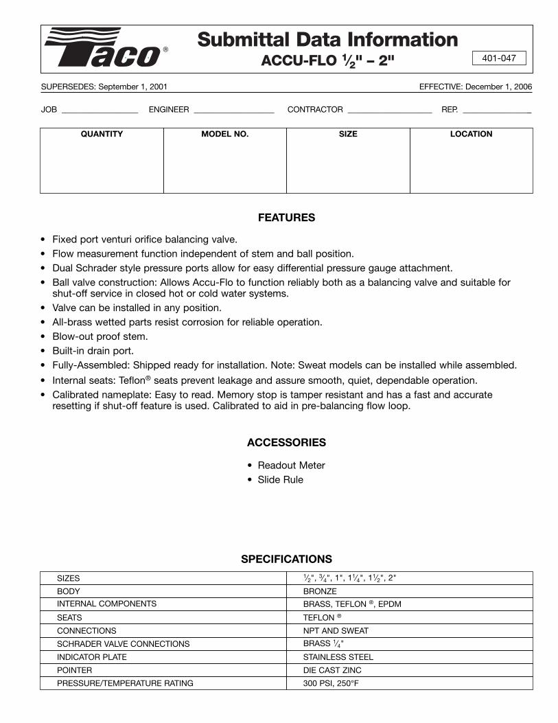
Submittal Data InformationACCU-FLO 1⁄2" – 2" 401-047
SUPERSEDES: September 1, 2001 EFFECTIVE: December 1, 2006
JOB ___________________ ENGINEER ____________________ CONTRACTOR _____________________ REP. _________________
QUANTITY MODEL NO. LOCATION
FEATURES
• Fixed port venturi orifice balancing valve.• Flow measurement function independent of stem and ball position.• Dual Schrader style pressure ports allow for easy differential pressure gauge attachment.• Ball valve construction: Allows Accu-Flo to function reliably both as a balancing valve and suitable for
shut-off service in closed hot or cold water systems. • Valve can be installed in any position.• All-brass wetted parts resist corrosion for reliable operation.• Blow-out proof stem.• Built-in drain port.• Fully-Assembled: Shipped ready for installation. Note: Sweat models can be installed while assembled.
• Internal seats: Teflon® seats prevent leakage and assure smooth, quiet, dependable operation.• Calibrated nameplate: Easy to read. Memory stop is tamper resistant and has a fast and accurate
resetting if shut-off feature is used. Calibrated to aid in pre-balancing flow loop.
ACCESSORIES
• Readout Meter• Slide Rule
SPECIFICATIONS
SIZE
SIZES 1⁄2", 3⁄4", 1", 11⁄4", 11⁄2", 2"
BODY BRONZE
SEATS TEFLON ®
CONNECTIONS NPT AND SWEAT
SCHRADER VALVE CONNECTIONS BRASS 1⁄4"
INDICATOR PLATE STAINLESS STEEL
POINTER DIE CAST ZINC
PRESSURE/TEMPERATURE RATING 300 PSI, 250°F
INTERNAL COMPONENTS BRASS, TEFLON ®, EPDM

Do it Once. Do it Right.®
TACO, INC., 1160 Cranston Street, Cranston, RI 02920 Telephone: (401) 942-8000 FAX: (401) 942-2360.TACO (Canada), Ltd., 6180 Ordan Drive, Mississauga, Ontario L5T 2B3. Telephone: 905/564-9422. FAX: 905/564-9436.
Visit our web site at: http://www.taco-hvac.com
Printed in USA
Copyright 2006
TACO, Inc.
1⁄2" 3⁄4" 1" 11⁄4" 11⁄2" 2" 21⁄2" 3"
4"
1⁄2" 3⁄4" 1" 11⁄4" 11⁄2" 2" 21⁄2" 3" 4"
6-26-96
.1 .2 .3 .4 .5 .6 .8 1 2 3 4 5 6 8 10 20 30 40 60 80 100 200 400 600 10001
2
3
4
56
8
10
20
30
40
5060
80
100
200
300
400
500600
50 70 300 500 8007 909.7 .9
1⁄2"-2" SWEAT & THREADDIMENSION DIAGRAMS
FLOW MEASUREMENT CHART
DIF
FE
RE
NT
IAL
PR
ES
SU
RE
- IN
CH
ES
WAT
ER
FLOW - GALLONS/MINUTE
DIMENSIONS MATERIAL WEIGHTSA B C DSIZE PRODUCT NO. CONNECTION
INCHES MM INCHES MM INCHES MM INCHES MMBODY VENTURI LBS. KG.
CV - FULLOPEN
POSITION
ACUF-050-AC SWEAT 31⁄4 82 2 51 2 51 11⁄2 38 BRONZE BRASS 11⁄4 0.51⁄2"ACUF-050-AT NPT 31⁄4 82 2 51 2 51 11⁄2 38 BRONZE BRASS 11⁄4 0.5
2.12
ACUF-075-AC SWEAT 31⁄4 82 21⁄8 54 21⁄8 54 11⁄2 38 BRONZE BRASS 11⁄4 0.53⁄4"ACUF-075-AT NPT 31⁄4 82 21⁄8 54 21⁄8 54 11⁄2 38 BRONZE BRASS 11⁄2 0.7
3.9
ACUF-100-AC SWEAT 4 101 21⁄8 54 21⁄8 54 15⁄8 41 BRONZE BRASS 11⁄2 0.71"
ACUF-100-AT NPT 4 101 21⁄8 54 21⁄8 54 15⁄8 41 BRONZE BRASS 2 0.98.4
ACUF-125-AC SWEAT 51⁄8 130 21⁄2 63 23⁄8 60 2 51 BRONZE BRASS 31⁄2 1.611⁄4"
ACUF-125-AT NPT 51⁄8 130 21⁄2 63 23⁄8 60 21⁄4 57 BRONZE BRASS 33⁄4 1.717.3
ACUF-150-AC SWEAT 57⁄8 149 25⁄8 67 21⁄2 64 23⁄16 56 BRONZE BRASS 41⁄2 2.111⁄2"
ACUF-150-AT NPT 57⁄8 149 25⁄8 67 21⁄2 64 23⁄4 70 BRONZE BRASS 51⁄4 2.428.3
ACUF-200-AC SWEAT 63⁄4 171 23⁄4 70 23⁄4 70 23⁄4 70 BRONZE BRASS 63⁄4 3.12"
ACUF-200-AT NPT 63⁄4 171 23⁄4 70 23⁄4 70 33⁄8 86 BRONZE BRASS 8 3.662.3
ACCU-FLO DIMENSIONS
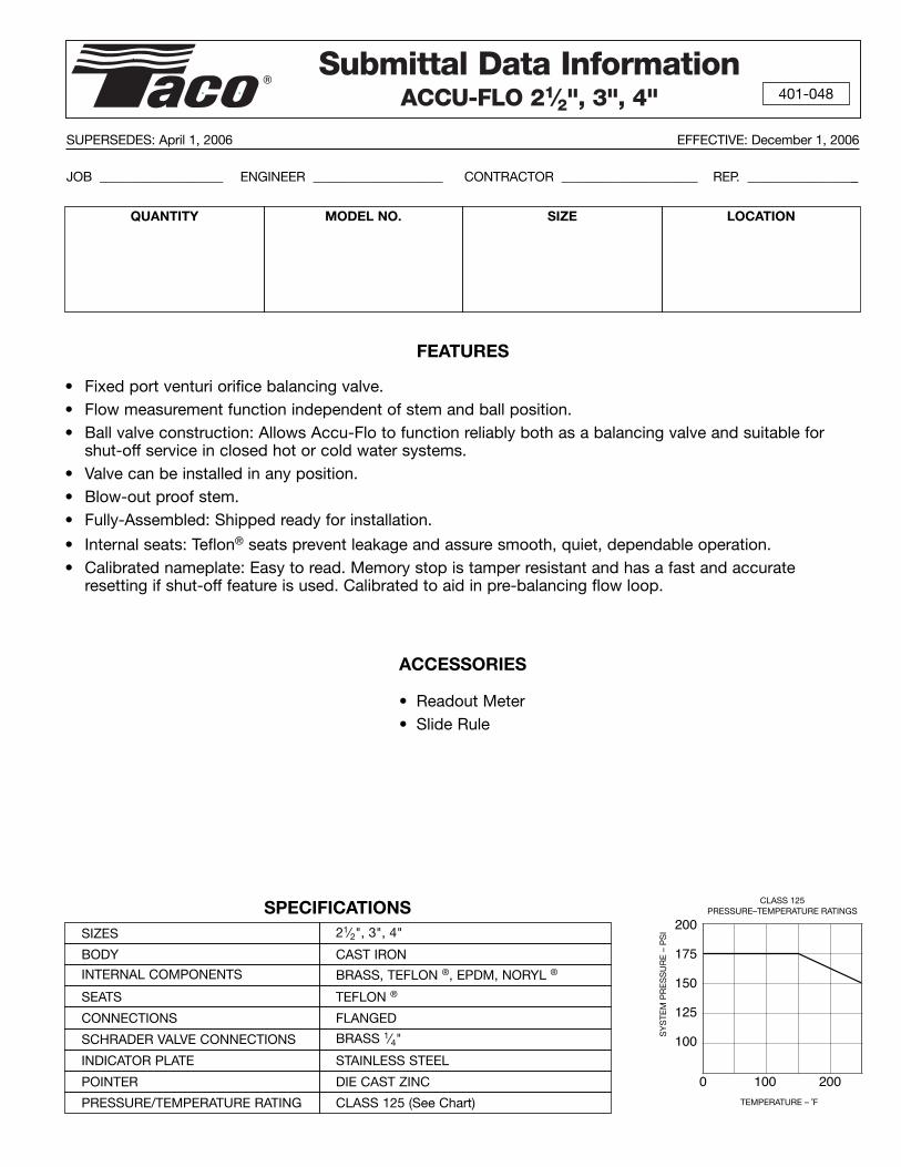
Submittal Data InformationACCU-FLO 21⁄2", 3", 4" 401-048
SUPERSEDES: April 1, 2006 EFFECTIVE: December 1, 2006
JOB ___________________ ENGINEER ____________________ CONTRACTOR _____________________ REP. _________________
QUANTITY MODEL NO. LOCATION
FEATURES
• Fixed port venturi orifice balancing valve.• Flow measurement function independent of stem and ball position.• Ball valve construction: Allows Accu-Flo to function reliably both as a balancing valve and suitable for
shut-off service in closed hot or cold water systems. • Valve can be installed in any position.• Blow-out proof stem.• Fully-Assembled: Shipped ready for installation.
• Internal seats: Teflon® seats prevent leakage and assure smooth, quiet, dependable operation.• Calibrated nameplate: Easy to read. Memory stop is tamper resistant and has a fast and accurate
resetting if shut-off feature is used. Calibrated to aid in pre-balancing flow loop.
ACCESSORIES
• Readout Meter• Slide Rule
SIZE
SIZES 21⁄2", 3", 4"
BODY CAST IRON
SEATS TEFLON ®
CONNECTIONS FLANGED
SCHRADER VALVE CONNECTIONS BRASS 1⁄4"
INDICATOR PLATE STAINLESS STEEL
POINTER DIE CAST ZINC
PRESSURE/TEMPERATURE RATING CLASS 125 (See Chart)
0 100 200TEMPERATURE – ˚F
200
175
150
125
100
SY
STE
M P
RE
SS
UR
E –
PS
I
CLASS 125PRESSURE–TEMPERATURE RATINGSSPECIFICATIONS
INTERNAL COMPONENTS BRASS, TEFLON ®, EPDM, NORYL ®
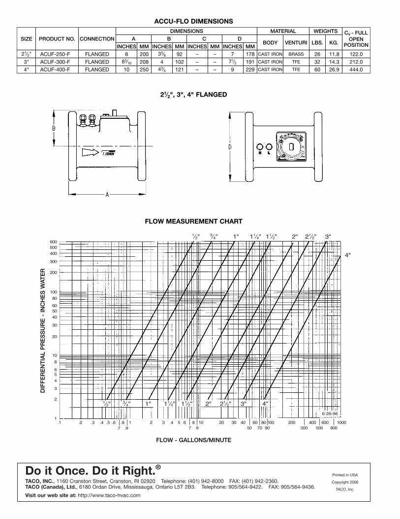
Do it Once. Do it Right.®
TACO, INC., 1160 Cranston Street, Cranston, RI 02920 Telephone: (401) 942-8000 FAX: (401) 942-2360.TACO (Canada), Ltd., 6180 Ordan Drive, Mississauga, Ontario L5T 2B3. Telephone: 905/564-9422. FAX: 905/564-9436.
Visit our web site at: http://www.taco-hvac.com
Printed in USA
Copyright 2006
TACO, Inc.
1⁄2" 3⁄4" 1" 11⁄4" 11⁄2" 2" 21⁄2" 3"
4"
1⁄2" 3⁄4" 1" 11⁄4" 11⁄2" 2" 21⁄2" 3" 4"
6-26-96
.1 .2 .3 .4 .5 .6 .8 1 2 3 4 5 6 8 10 20 30 40 60 80 100 200 400 600 10001
2
3
4
56
8
10
20
30
40
5060
80
100
200
300
400
500600
50 70 300 500 8007 909.7 .9
21⁄2", 3", 4" FLANGED
FLOW MEASUREMENT CHART
DIF
FE
RE
NT
IAL
PR
ES
SU
RE
- IN
CH
ES
WAT
ER
FLOW - GALLONS/MINUTE
DIMENSIONS MATERIAL WEIGHTSA B C DSIZE PRODUCT NO. CONNECTION
INCHES MM INCHES MM INCHES MM INCHES MMBODY VENTURI LBS. KG.
CV - FULLOPEN
POSITION
21⁄2" ACUF-250-F FLANGED 8 200 35⁄8 92 – – 7 178 CAST IRON BRASS 26 11.8
3" FLANGED 83⁄16 208 4 102 – – 71⁄2 191 CAST IRON TFE 32 14.34"
ACUF-300-FFLANGED 10 250 43⁄4 121 – – 9 229 CAST IRON TFE 60 26.9
122.0
444.0ACUF-400-F212.0
ACCU-FLO DIMENSIONS

Instruction Sheet
1/2" - 4" ACCU-FLO Circuit Setter Flow Balancing Valve
402-051
SUPERSEDES: January 1, 1997 EFFECTIVE: January 1, 2007
VALVE INSTALLATION
1. The valve may be installed in any position. Place thevalve in a position which provides for convenient accessto the pressure port connections for the differential pres-sure gauge hoses, easy access to the memory stopscrews, and easy reading of the scale.
2. Caution should be used when sweat style valves areinstalled to prevent overheating the valve. Use a torchwith a sharp pointed flame. Direct the flame with care sothat the valve body is not subjected to excessive heat.The valve should be in the closed position during sweat-ing. The use of low temperature solders is recommended.These valves should not be brazed.
VALVE OPERATION
1. For presetting, use the appropriate slide rule setting nec-essary to achieve the desired pressure drop.
2. To measure flow, connect the TACO PRESSURE GAUGE(No. 779 0-10", 0-100" dual recommended, No. 775 0-135", 0-100' for higher pressure drops as an alternate)to the pressure port connections.
A–Position the meter case in a safe location adjacent tothe valve.
CAUTION:B–Take care in removing the pressure port connection
caps on the ACCU-FLO valve, since they will be at thesame temperature as the pipeline. There may be somefluid trapped behind the cap. Slowly unscrew the capsand look for continuous leakage. Continuous leakagemay indicate a failure of the stem seal in the pressureport connection. Process fluid at temperature andunder pressure may be present. If continuous leakageis present, do not remove the cap. Appropriate correc-tive action must be taken.
C–Connect the gauge hoses to the pressure port connec-tions, the RED hose to the port adjacent to the letter Hon the valve body and the YELLOW hose to the otherport indicated by the letter L on the valve body.
D–The pressure port connection valves open automati-cally as the hoses are screwed onto the fitting, allow-ing fluid to flow into the meter. NOTE: If the hoses areconnected one at a time, the second hose will bleedfluid as the first hose is connected and fluid flows intothe meter. This will stop as the meter fills one side ofthe measurement cylinder.
E–Read the pressure drop on the appropriate meterscale. NOTE: If you use a meter graduated in feet ofwater, convert the reading to inches. Read the flow ingallons per minute on the appropriate slide rule scale.
F–When reading pressure drop, wait a sufficient amountof time to insure that all air has been bled from thehoses and meter. Refer to the gauge operating instruc-tions.
G–Adjust the ACCU-FLO valve by turning the valve stemuntil the desired pressure drop is achieved. On allvalves from 1/2" thru 4", the flow measurement is inde-pendent of indicator setting.
H–When the proper setting has been achieved, slightlyloosen the two socket head cap screws and rotate theMemory Stop around until it touches the back side ofthe indicator. Then tighten the screws to securely setthe open memory position. The Memory Stop is usedto indicate the last set open position. It should not beused as a “hard” stop which can take a lot of force.
I–Review the pressure drop, and if it is correct, removethe hoses and replace the pressure port caps.
PLANT I.D. 001-993

SISCO Manufacturing Company
Pressure & Temperature Test Plugs
Click Here For Test Plug Installation Instructions
Model Number
NominalSize (in)
OAL (in)
MaterialPressure/
Temperature
Lower Connection
(in)
Body Hex (in)
Cap Hex (in)
Core Material
BNO-125 1/8 NPT 1-1/4 Brass 350F/1000PSI 1/8 NPT 13/16 9/16 NordelBNO-250 1/4 NPT 1-1/2 Brass 350F/1000PSI 1/4 NPT 1-1/16 1-1/2 NordelBNO-252 1/4 NPT 2-1/2 Brass 350F/1000PSI 1/4 NPT 1-1/16 1-1/2 NordelBNO-254 1/4 NPT 4 Brass 350F/1000PSI 1/4 NPT 1-1/16 1-1/2 NordelBNO-375 3/8 NPT 1-1/2 Brass 350F/1000PSI 3/8 NPT 1-1/16 1-1/2 NordelBNO-500 1/2 NPT 1-1/2 Brass 350F/1000PSI 1/2 NPT 1-1/16 1-1/2 NordelBNE-125 1/8 NPT 1-1/4 Brass 200F/1000PSI 1/8 NPT 13/16 9/16 NeopreneBNE-250 1/4 NPT 1-1/2 Brass 200F/1000PSI 1/4 NPT 1-1/16 1-1/2 NeopreneBNE-252 1/4 NPT 2-1/2 Brass 200F/1000PSI 1/4 NPT 1-1/16 1-1/2 NeopreneBNE-254 1/4 NPT 4 Brass 200F/1000PSI 1/4 NPT 1-1/16 1-1/2 NeopreneBNE-375 3/8 NPT 1-1/2 Brass 200F/1000PSI 3/8 NPT 1-1/16 1-1/2 NeopreneBNE-500 1/2 NPT 1-1/2 Brass 200F/1000PSI 1/2 NPT 1-1/16 1-1/2 NeopreneSSNO-
2501/4 NPT 1-1/2 SS 304 350F/1000PSI 1/4 NPT 1-1/16 1-1/2 Nordel
SSNE-250 1/4 NPT 1-1/2 SS 304 200F/1000PSI 1/4 NPT 1-1/16 1-1/2 NeopreneSSNO-
5001/2 NPT 1-1/2 SS 304 350F/1000PSI 1/2 NPT 1-1/16 1-1/2 Nordel
SSNE-500 1/2 NPT 1-1/2 SS 304 200F/1000PSI 1/2 NPT 1-1/16 1-1/2 Neoprene
Pressure & Temperature Test Plugs Acessories
PCR Plastic Cap Retainer - Available for all test plugsBTX-250 1/4" x 1-3/4" bottom fit brass test plug extensionBTXX-250 1/4" x 2-3/4" bottom fit brass test plug extensionBTX-500 1/2" x 1-3/4" bottom fit brass test plug extension GA-063 Gauge Adaptor 2-3/4" OAL x 1-3/4" x 0.063" probeGA-125 Gauge Adaptor 2-3/4" OAL x 1-3/4" x 0.125" probeGA-125S Gauge Adaptor 2-1/4" OAL x 1-3/4" x 0.125" probePG Probe guard for all gauge adapters
625 Hollywood Avenue Cherry Hill, NJ 08002-2822 Phone: 856.486.7550 Fax: 856.486.7551
SISCO Manufacturing Company
Page 1 of 1Sisco P/T Plugs - Pressure & Temperature Test Plugs
1/5/2007http://www.siscomfg.com/plugskits.asp?printable=printable

OESCRIPTIONS GAUGES
THERMOMETERS
ACCESSORIES AND GAIJGE
TEST KITS
lNsrALL A SSSSsISCO 1t4 tl€ 3/a^. l/2. NPT OR BSp)TEST PLUG OF SOLID ERA5S (STAINLESS STEEL OR
VALVE OR VEssEL PLUGSROJECT ORAWING5 TEST PLUGCORE OF NOROEL. G@O UP TO
35O' F FOR WATER. (OR NEOPRENE TO 2C1O" F FOR
I OOO PSIG PLUG SHALL BE CAPABLE
FOR I / 4 ' ( 3 /A OR 1 /2 'NPT OR BSP) TEST PLUG ONLYOWNER SHALL BE PROV OEO WI'H ONE ( I ) M^STER TEST
NE oR Two 2 112' oR 3 U2
I/A O D PROBE(s) AND TWO 5 STEM
O 22O ' F AND ONE 50 55OJ F IN A ST IROY CU5TOM
FOR I /A NPT lOR BSP}TEB 2 OWNER S tsOULD BE P
R t u O 2 t / 2 0 R 3 1 / 2
GAUGE AOAPTERIs ) GA 063 THAT HAVE 1 / I 6 O D ANDTEMPERATURE READINGS ARE
1 'qz I
2 1/2'OR 3 1t/ D AL FACE
NPT EXTENSDN ARASS
tffi-- mirqp* '" . - t I l t .
lil =)PLASTIC CAP BETAINER
I,f\-+_-'a\l1\j2.--\/l
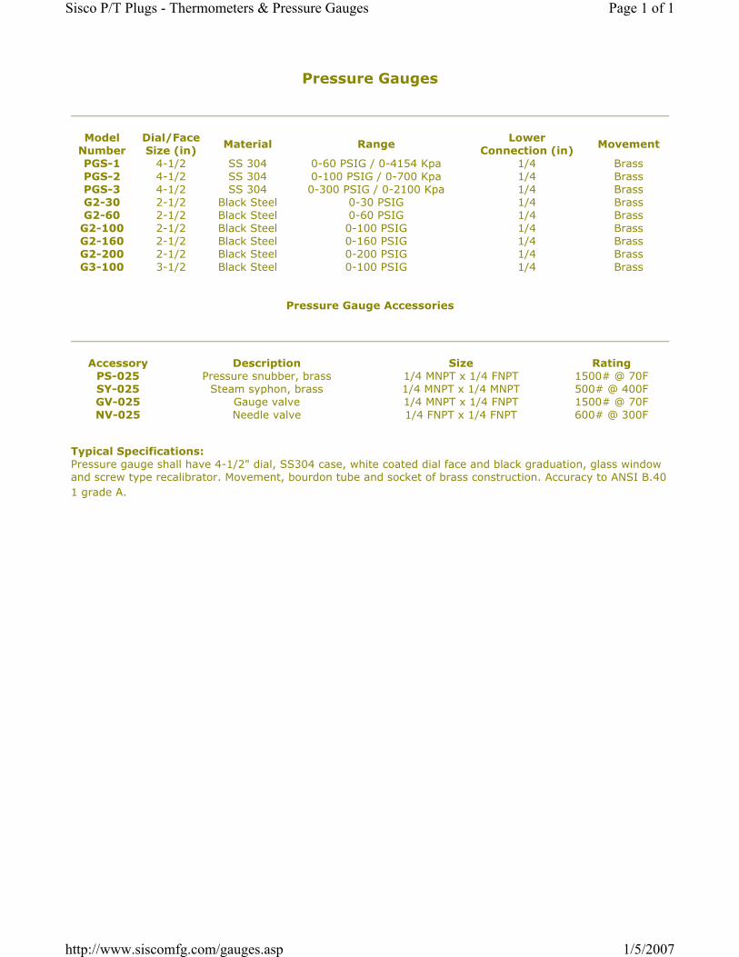
Pressure Gauges
Model Number
Dial/Face Size (in)
Material RangeLower
Connection (in)Movement
PGS-1 4-1/2 SS 304 0-60 PSIG / 0-4154 Kpa 1/4 BrassPGS-2 4-1/2 SS 304 0-100 PSIG / 0-700 Kpa 1/4 BrassPGS-3 4-1/2 SS 304 0-300 PSIG / 0-2100 Kpa 1/4 BrassG2-30 2-1/2 Black Steel 0-30 PSIG 1/4 BrassG2-60 2-1/2 Black Steel 0-60 PSIG 1/4 Brass
G2-100 2-1/2 Black Steel 0-100 PSIG 1/4 BrassG2-160 2-1/2 Black Steel 0-160 PSIG 1/4 BrassG2-200 2-1/2 Black Steel 0-200 PSIG 1/4 BrassG3-100 3-1/2 Black Steel 0-100 PSIG 1/4 Brass
Pressure Gauge Accessories
Accessory Description Size RatingPS-025 Pressure snubber, brass 1/4 MNPT x 1/4 FNPT 1500# @ 70FSY-025 Steam syphon, brass 1/4 MNPT x 1/4 MNPT 500# @ 400FGV-025 Gauge valve 1/4 MNPT x 1/4 FNPT 1500# @ 70FNV-025 Needle valve 1/4 FNPT x 1/4 FNPT 600# @ 300F
Typical Specifications: Pressure gauge shall have 4-1/2" dial, SS304 case, white coated dial face and black graduation, glass window and screw type recalibrator. Movement, bourdon tube and socket of brass construction. Accuracy to ANSI B.40 1 grade A.
Page 1 of 1Sisco P/T Plugs - Thermometers & Pressure Gauges
1/5/2007http://www.siscomfg.com/gauges.asp

9.. SISCCO Manufacnrins, tnc! I Soencer Indusrni Sales. Inc
€;'
.OPGS'' SERTES PRSSSURE GAUGES
Dial SizeDial FaceGraduationsCaseRirrgPohlerRecalibratorLouer ConoectionSocketMovcmgntBourdon l ubeOvetpr€ssureAcouna.cy
4-1D"$;hite coatcd rEtalBlackStaiiless SteelStainless SreelAnodiz€d black alumbumSlotted screr,v� $.Fre1,r-1" NPT irra-ssBrassflrassBrass25Yo tull scaleANSI 840.1 Grade A
4-112'Dial
Model
1 PGS-o# PGS.I
* # PGS-2# PGS-2An PGS-3
PuNl Sc.lc {PSIC & KPAI
30'Tlg-0-30 ./-l 00-0-2000-60 I 0-4r 50-100 .i 0-7000-200 10-14000-300 / 0-2100
T^4 Ooantifv
TYpicsl Sp€cilicrti6Ptcssorc ga!8. shan havr +112" diat. SSi04 c!3e, white c@t€d dirl {ace snd black srduations, glass eindoq &
scrcw type rccalibrdor. Brrss movenest bourdon hrbe & soclet wilh accuracy lo ANSI 840.1 crsd. A
Acc€sgola# PS-025# sY-025* GV-0254 NV-025
DescriptionPr€ssure sBubber. bassStEaI! syphon- steolGauge valve, brassNeedle valve, brass
Siz€'/." MNPT x %" F\?T%'MNPTx 'l" MrIPT%" M\iPT x %" FNPT%"FNPTxt "F , \?T
R.tinel s00* @ 70F500# @ 400Fr500# @ 70F600# @ 300F
Pmi.ct:
Purrtrser:

All specifications are subject to change without notice.
G2.BIM/E Rev. D 05/02/2001
All stainless steel bimetal thermometerModel A and ENominal size 3", 5", 100 mm or 160 mmAccuracy: Class 1,0 (DIN) (100 and 160 mm)
1% to ASME (3“ and 5“)Features• Rugged stainless steel construction• Fast response• Protection IP65• Antiparallax Maxivision® dial (type E)• External zero adjustment (type E)• Dry or liquid filled• Silicone damped coil
Ranges-50°C ... 50°C up to 0°C ... 500°C-80°F ... 120°C up to 200°F ... 1000°F
ApplicationsChemical and petrochemical industryMachine and apparatus constructionFood and beverage industryPulp and paper industry
Technical specification AM, AE, AI, A3B EM, EE, EI, E3BDial size [mm] 100 160 3" (80 mm) 5" (125 mm)Construction Cylindrical case with bayonet ring Cylindrical case with crimp ring, hermetically sealed
and external adjustmentBimetallic coilMeasuring principle
Range [°C]
Temperature limits for rangesmax. process overtemperature
StemDiameterLength
0/50 0/60 0/80 0/100 0/120 0/150 0/160 0/200 0/250 0/300 0/400 0/50010/150 50/300 50/450 100/500 -10/50 -10/110 -20/40 -20/60 -20/160 -20/180-25/25 -30/50 -30/70 -40/40 -40/60 -40/160 -50/50Ranges in °F and dual scales on request< 120°C ≥ 120°C and < 290°C ≥ 290°C100% of span 50% of span max. 425°C for continuous service
6 mm, 8 mm, ¼" (6,4 mm), 3/8" (9,6 mm)63 ... 1000 mm, minimum length depends on range
Process connection PlainG ½ B male, G ½ female, ½" NPT male or ½" NPT femaleG ¾ B male, G ¾ female, ¾" NPT male or ¾" NPT femaleG 1 B male, G 1 female, 1" NPT male or 1" NPT female, others on requestfixed, adjustable or with swivel nut
Connection location Back, lower (not for dial size 3") and every angle (rotatable over 360°)
Stainless steel AISI 316Ti (1.4571)Stainless steel AISI 316Ti (1.4571)Stainless steel AISI 304 (1.4301), optional AISI 316 (1.4401) for Type AInstrument glass, optional laminated safety glass or acrylic glassAluminum, black markings on white background Aluminum, black markings on white background,
antiparallax, Maxivision® scale
MaterialConnectionStemCase/ringWindowDialPointer
Aluminum, blackAccuracy Class 1 (dry) and class 2 (liquid filled) according DIN 16 203Protection according EN 60 529/IEC 529 IP65Filling liquids Silicone, not for lower connection, max. to 150°C and standard acrylic glassWeight [kg]
Connection locationDryFilled
Back0,350,6
Lower0,55---
Everyangle0,550,8
Back0,71,0
Lower0,9---
Everyangle0,91,2
Back0,20,6
---Everyangle0,40,7
Back0,40,7
Lower0,6---
Everyangle0,60,9
Accessories, options Thermowells, dual scale, calibration certification

DRESSER EUROPE GmbH Instrument Division Website: www.dresserinstruments.com e-Mail: [email protected]ße 1, D-52499 BaesweilerP.O. Box 11 20, D-52490 BaesweilerTel.: +49 (0) 24 01 80 80, Fax: +49 (0) 24 01 80 81 25
France206 Rue des Campanules, Le MandinetF-77185 Lognes Tel.: +33 (0) 1 60 37 25 30
Fax: +33 (0) 1 60 37 25 39
United KingdomEast GillibrandsSkelmersdale, Lancashire WN8 9TUTel.: +44 (0) 16 95 52 600, Fax: +44 (0) 16 95 52 693
General dimensions [mm]
Model A Model E
S = stem length (specify by customer)
Order informationSize Type and stem
executionFilling Process
connectionConnectionorientation
Stemlength
Range Engineer-ing unit
Options
(100)100 mm
(160)160 mm
Metric housingwith bayonet ring(IP65)
(AM) 6 mm
(AE) 8 mm
(AI) ¼"(6,4 mm)
(A3B) 3/8"(9,6 mm)
(30)3"(80 mm)
(50)5"(125 mm)
ANSI housinghermeticallysealed (IP65)
(EM) 6 mm
(EE) 8 mm
(EI) ¼"(6,4 mm)
(E3B) 3/8"(9,6 mm)
(=) Standard(no filling)
(L) Liquid filledwith siliconemax. up to150°C(not for lowerconnection)
(040) Plain
(042) Union outlet½" NPT male
(060) Fixed½" NPT male
(061) FixedG ½ B male
(70) Adjustable union½" NPT male
(071) Adjustable unionG ½ B male
(072) Adjustable union¾" NPT male
(074) Adjustable union½" NPT female
(080) Swivel nutG ½ B male
(081) Swivel nutG ½ female
(L) Lower 1)
(R) Back
(E) Everyangle(360°)
1)not for dialsize 3"
65 to1000 mm
0/ 50 1)
0/ 60 1)
0/ 80 1)
0/ 100 0/ 120 0/ 150 0/ 160 0/ 200 0/ 250 1)
0/ 300 0/ 400 1)
0/ 500 1)
10/ 150 50/ 300 50/ 450100/ 500 1)
-10/ 50 1)
-10/ 110-20/ 40 1)
-20/ 60 1)
-20/ 160-20/ 180-25 25 1)
-30/ 50 1)
-30/ 70-30/ 170-40/ 40 1)
-40/ 60-40/ 100-40/ 160-50/ 501)
minimumstem length100 mm
°C
°F seetable
dual scaleon request
(NH) Tagging wired
(DA) Dial marking
(RT) Stepped stem
(CS) Dual scale
(PD) Acrylic glass
(SG) Safety glass
(SH) Red set handstationary
(YW) AISI 316housing (not forlower housing andsize 3")
How to order
Size Type and stemexecution
Filling Processconnection
Connectionorientation
Stemlength
Range Engineeringunit
Option
50 EE = 070 E 150 0/200 C NH
0/ 100 0/ 150 1)
0/ 200 0/ 250 0/ 300 0/ 350 0/ 500 20/ 120 1)
30/ 130 1)
30/ 240 1)
50/ 300 50/ 400 50/ 550 80/ 180100/ 800160/ 360170/ 270200/ 400200/ 700 1)
200/1000 1)
-40/ 120-40/ 160-20/ 120 1)
-80 120-100/ 0 1)
-10/ 1001)
minimumstem length100 mm
°F
dual scaleon request
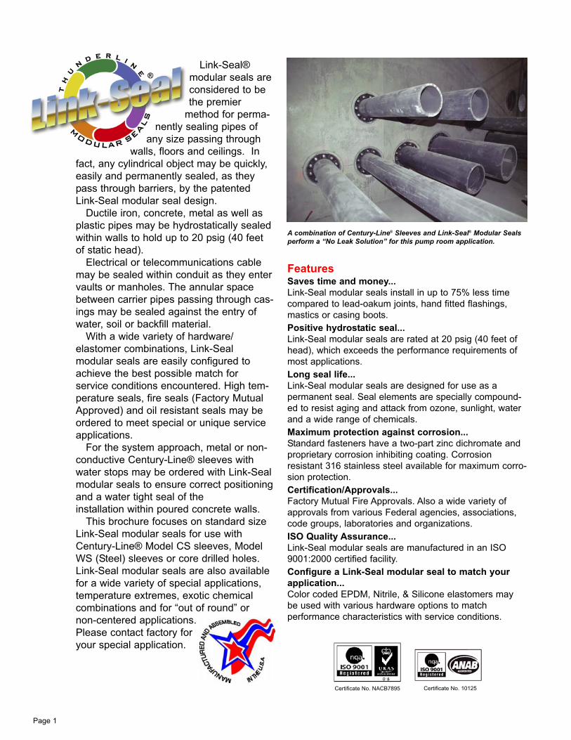
FeaturesSaves time and money...
Link-Seal modular seals install in up to 75% less time
compared to lead-oakum joints, hand fitted flashings,
mastics or casing boots.
Positive hydrostatic seal...
Link-Seal modular seals are rated at 20 psig (40 feet of
head), which exceeds the performance requirements of
most applications.
Long seal life...
Link-Seal modular seals are designed for use as a
permanent seal. Seal elements are specially compound-
ed to resist aging and attack from ozone, sunlight, water
and a wide range of chemicals.
Maximum protection against corrosion...
Standard fasteners have a two-part zinc dichromate and
proprietary corrosion inhibiting coating. Corrosion
resistant 316 stainless steel available for maximum corro-
sion protection.
Certification/Approvals...
Factory Mutual Fire Approvals. Also a wide variety of
approvals from various Federal agencies, associations,
code groups, laboratories and organizations.
ISO Quality Assurance...
Link-Seal modular seals are manufactured in an ISO
9001:2000 certified facility.
Configure a Link-Seal modular seal to match your
application...
Color coded EPDM, Nitrile, & Silicone elastomers may
be used with various hardware options to match
performance characteristics with service conditions.
A combination of Century-Line® Sleeves and Link-Seal® Modular Sealsperform a “No Leak Solution” for this pump room application.
Page 1
Certificate No. NACB7895 Certificate No. 10125
Link-Seal®
modular seals are
considered to be
the premier
method for perma-
nently sealing pipes of
any size passing through
walls, floors and ceilings. In
fact, any cylindrical object may be quickly,
easily and permanently sealed, as they
pass through barriers, by the patented
Link-Seal modular seal design.
Ductile iron, concrete, metal as well as
plastic pipes may be hydrostatically sealed
within walls to hold up to 20 psig (40 feet
of static head).
Electrical or telecommunications cable
may be sealed within conduit as they enter
vaults or manholes. The annular space
between carrier pipes passing through cas-
ings may be sealed against the entry of
water, soil or backfill material.
With a wide variety of hardware/
elastomer combinations, Link-Seal
modular seals are easily configured to
achieve the best possible match for
service conditions encountered. High tem-
perature seals, fire seals (Factory Mutual
Approved) and oil resistant seals may be
ordered to meet special or unique service
applications.
For the system approach, metal or non-
conductive Century-Line® sleeves with
water stops may be ordered with Link-Seal
modular seals to ensure correct positioning
and a water tight seal of the
installation within poured concrete walls.
This brochure focuses on standard size
Link-Seal modular seals for use with
Century-Line® Model CS sleeves, Model
WS (Steel) sleeves or core drilled holes.
Link-Seal modular seals are also available
for a wide variety of special applications,
temperature extremes, exotic chemical
combinations and for “out of round” or
non-centered applications.
Please contact factory for
your special application.

Model “C or L” Link-Seal Modular Seals
Suitable for use in water, direct ground burial and
atmospheric conditions. Provides electrical isola-
tion where cathodic protection is required.
Type: Standard
Seal Element: EPDM (Black) or EPDM (Blue)
Pressure Plates: Reinforced Nylon Polymer
Bolts & Nuts: Steel with 2-part Zinc Dichromate
& proprietary corrosion inhibiting coating.
Temp. Range: -40 to +250ºF (-40 to +121ºC)*
Model “S-316” Link-Seal Modular Seals
For chemical processing & waste water treat-
ment. EPDM rubber is resistant to most inorganic
acids and alkalis, some organic chemicals (ace-
tone, alcohol, ketones).
Type: Stainless
Seal Element: EPDM (Black) or EPDM (Blue)
Pressure Plates: Reinforced Nylon Polymer
Bolts & Nuts: 316 Stainless Steel
Temp. Range: -40 to +250ºF (-40 to +121ºC)*
Model “O” Link-Seal Modular Seals
Nitrile rubber is resistant to oils, fuel and many
solvents (gasoline, motor oil, kerosene, methane,
jet fuel, hydraulic fluid, water, etc.)
Type: Oil Resistant
Seal Element: Nitrile (Green) Note: Not U.V. resistant.
Pressure Plates: Reinforced Nylon Polymer
Bolts & Nuts: Steel with 2-part Zinc Dichromate
& proprietary corrosion inhibiting coating.
Temp. Range: -40 to +210ºF (-40 to +99ºC)*
Model “OS-316” Link-Seal Modular Seals
Combination of oil resistant rubber and stainless
steel hardware.
Type: Oil Resistant
Seal Element: Nitrile (Green) Note: Not U.V. resistant.
Pressure Plates: Reinforced Nylon Polymer
Bolts & Nuts: 316 Stainless Steel
Temp. Range: -40 to +210 ºF (-40 to +99ºC)*
Model “T” Link-Seal Modular Seals
Silicone rubber is ideal for temperature
extremes. “T” model is one-hour Factory Mutual
approved.
Type: High/Low Temperature
Seal Element: Silicone (Grey)
Pressure Plates: Steel Zinc Dichromate
Bolts: Steel with 2-part Zinc Dichromate
& proprietary corrosion inhibiting coating.
Temp. Range: -67 to +400ºF (-55 to +204ºC)*
Model “FD/FS” Link-Seal Modular Seals
Double seal for added protection.
Type: Fire Seals
Seal Element: Silicone (Grey)
Pressure Plates: Steel Zinc Dichromate
Bolts: Steel with 2-part Zinc Dichromate
& proprietary corrosion inhibiting coating.
Temp. Range: -67 to +400ºF (-55 to +204ºC)*
Century-Line® Model CS Sleeves are idealfor poured wall construction. Made of HDPEthermoplastic, they are lightweight and easy tohandle. Molded-in waterstop and reinforcingribs serve to anchor the sleeve in the wall andresist pour forces. Nailer end caps are providedto make placement in forms simple and accu-rate. Sleeves are available in 16 diameters, upto 25”, and any length. In the event of a fieldchange they can be shortened with ordinaryhand tools.
Model WS Steel Sleeves are made fromheavy-wall welded or seamless pipe. A full cir-cle waterstop plate acts as positive water sealand anchor to prevent thrust movement. The 2”collar (water-stop) is continuously welded onboth sides. Model WS is available in a widerange of diameters and any length. Sleevesare protected by a coating of red primer. Hotdip galvanizing is available on request.
Link-Seal Modular Seals are also commonlyinstalled in cored wall openings or pre-castopenings such as those formed by use of Cell-Cast® Disks for pipe penetration hole forms.See Cell-Cast Disk (page 4) or contact PSI formore information.
Link-Seal® Modular Seal Options Sleeve Options
with EPDM Seal Elements
with Nitrile Seal Elements
with Silicone Seal Elements
Page 2
*Note: Sustains a constant temp. of 325ºF.
(163ºC.) = Sustained operation near temperature
limits may affect life expectancy.
* = Sustained operation near temperature limits may affect lifeexpectancy.
* = Sustained operation near temperature limits may affect lifeexpectancy.
Silicone (Grey)
Nitrile (Green)
EPDM (Black Seal
Elements)
EPDM (Blue Seal Elements)
Note: Model “L” (Blue) is a lowdurometer EPDM rubber for thin
walled pipe applications
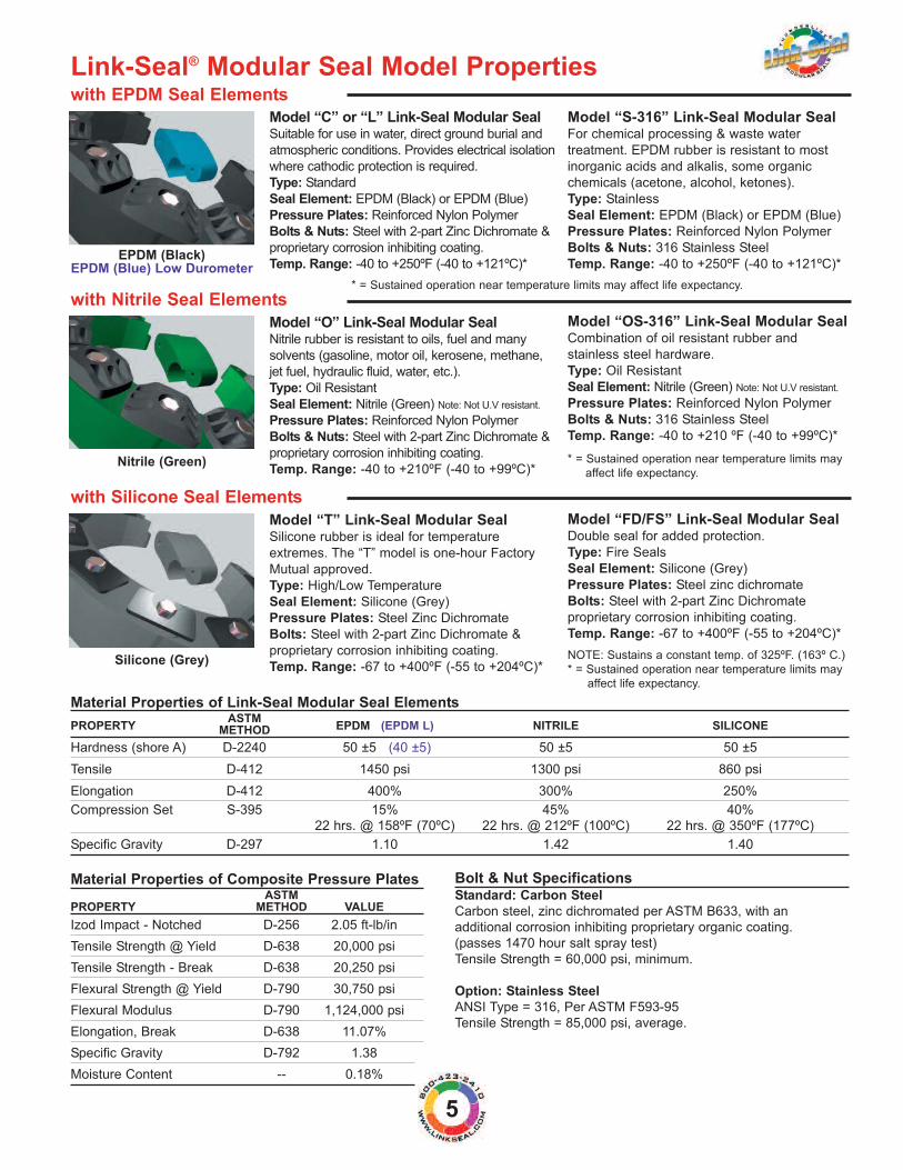
Bolt & Nut SpecificationsStandard: Carbon Steel
Carbon steel, zinc dichromated per ASTM B633, with an
additional corrosion inhibiting proprietary organic coating.
(passes 1470 hour salt spray test)
Tensile Strength = 60,000 psi, minimum.
Option: Stainless Steel
ANSI Type = 316, Per ASTM F593-95
Tensile Strength = 85,000 psi, average.
Link-Seal® Modular Seal Model Properties
Model “C” or “L” Link-Seal Modular SealSuitable for use in water, direct ground burial and
atmospheric conditions. Provides electrical isolation
where cathodic protection is required.
Type: Standard
Seal Element: EPDM (Black) or EPDM (Blue)
Pressure Plates: Reinforced Nylon Polymer
Bolts & Nuts: Steel with 2-part Zinc Dichromate &
proprietary corrosion inhibiting coating.
Temp. Range: -40 to +250ºF (-40 to +121ºC)*
Model “S-316” Link-Seal Modular SealFor chemical processing & waste water
treatment. EPDM rubber is resistant to most
inorganic acids and alkalis, some organic
chemicals (acetone, alcohol, ketones).
Type: Stainless
Seal Element: EPDM (Black) or EPDM (Blue)
Pressure Plates: Reinforced Nylon Polymer
Bolts & Nuts: 316 Stainless Steel
Temp. Range: -40 to +250ºF (-40 to +121ºC)*
Model “O” Link-Seal Modular SealNitrile rubber is resistant to oils, fuel and many
solvents (gasoline, motor oil, kerosene, methane,
jet fuel, hydraulic fluid, water, etc.).
Type: Oil Resistant
Seal Element: Nitrile (Green) Note: Not U.V resistant.
Pressure Plates: Reinforced Nylon Polymer
Bolts & Nuts: Steel with 2-part Zinc Dichromate &
proprietary corrosion inhibiting coating.
Temp. Range: -40 to +210ºF (-40 to +99ºC)*
Model “OS-316” Link-Seal Modular SealCombination of oil resistant rubber and
stainless steel hardware.
Type: Oil Resistant
Seal Element: Nitrile (Green) Note: Not U.V resistant.
Pressure Plates: Reinforced Nylon Polymer
Bolts & Nuts: 316 Stainless Steel
Temp. Range: -40 to +210 ºF (-40 to +99ºC)*
Model “T” Link-Seal Modular SealSilicone rubber is ideal for temperature
extremes. The “T” model is one-hour Factory
Mutual approved.
Type: High/Low Temperature
Seal Element: Silicone (Grey)
Pressure Plates: Steel Zinc Dichromate
Bolts: Steel with 2-part Zinc Dichromate &
proprietary corrosion inhibiting coating.
Temp. Range: -67 to +400ºF (-55 to +204ºC)*
Model “FD/FS” Link-Seal Modular SealDouble seal for added protection.
Type: Fire Seals
Seal Element: Silicone (Grey)
Pressure Plates: Steel zinc dichromate
Bolts: Steel with 2-part Zinc Dichromate
proprietary corrosion inhibiting coating.
Temp. Range: -67 to +400ºF (-55 to +204ºC)*
with EPDM Seal Elements
with Nitrile Seal Elements
with Silicone Seal Elements
Material Properties of Link-Seal Modular Seal ElementsASTM
PROPERTY METHOD EPDM (EPDM L) NITRILE SILICONE
Hardness (shore A) D-2240 50 ±5 (40 ±5) 50 ±5 50 ±5
Tensile D-412 1450 psi 1300 psi 860 psi
Elongation D-412 400% 300% 250%
Compression Set S-395 15% 45% 40%
22 hrs. @ 158ºF (70ºC) 22 hrs. @ 212ºF (100ºC) 22 hrs. @ 350ºF (177ºC)
Specific Gravity D-297 1.10 1.42 1.40
Material Properties of Composite Pressure PlatesASTM
PROPERTY METHOD VALUE
Izod Impact - Notched D-256 2.05 ft-lb/in
Tensile Strength @ Yield D-638 20,000 psi
Tensile Strength - Break D-638 20,250 psi
Flexural Strength @ Yield D-790 30,750 psi
Flexural Modulus D-790 1,124,000 psi
Elongation, Break D-638 11.07%
Specific Gravity D-792 1.38
Moisture Content -- 0.18%
NOTE: Sustains a constant temp. of 325ºF. (163º C.)
* = Sustained operation near temperature limits may
affect life expectancy.
EPDM (Black)EPDM (Blue) Low Durometer
Nitrile (Green)
Silicone (Grey)
5
* = Sustained operation near temperature limits may
affect life expectancy.
* = Sustained operation near temperature limits may affect life expectancy.
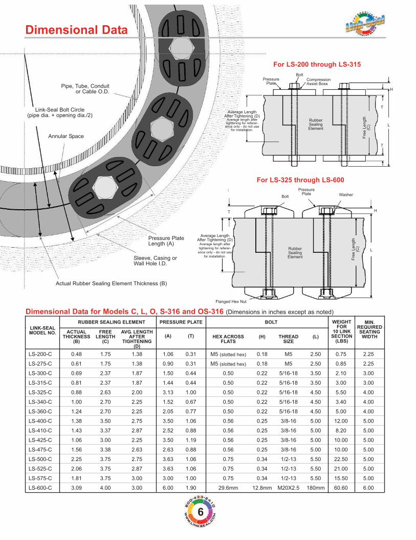
Dimensional Data for Models C, L, O, S-316 and OS-316 (Dimensions in inches except as noted)
RUBBER SEALING ELEMENT PRESSURE PLATE BOLT
ACTUAL FREE AVG. LENGTH(A) (T)THICKNESS LENGTH AFTER HEX ACROSS (H) THREAD (L)
(B) (C) TIGHTENING FLATS SIZE(D)
LS-200-C 0.48 1.75 1.38 1.06 0.31 M5 (slotted hex) 0.18 M5 2.50 0.75 2.25
LS-275-C 0.61 1.75 1.38 0.90 0.31 M5 (slotted hex) 0.18 M5 2.50 0.85 2.25
LS-300-C 0.69 2.37 1.87 1.50 0.44 0.50 0.22 5/16-18 3.50 2.10 3.00
LS-315-C 0.81 2.37 1.87 1.44 0.44 0.50 0.22 5/16-18 3.50 3.00 3.00
LS-325-C 0.88 2.63 2.00 3.13 1.00 0.50 0.22 5/16-18 4.50 5.50 4.00
LS-340-C 1.00 2.70 2.25 1.52 0.67 0.50 0.22 5/16-18 4.50 3.40 4.00
LS-360-C 1.24 2.70 2.25 2.05 0.77 0.50 0.22 5/16-18 4.50 5.00 4.00
LS-400-C 1.38 3.50 2.75 3.50 1.06 0.56 0.25 3/8-16 5.00 12.00 5.00
LS-410-C 1.43 3.37 2.87 2.52 0.88 0.56 0.25 3/8-16 5.00 8.20 5.00
LS-425-C 1.06 3.00 2.25 3.50 1.19 0.56 0.25 3/8-16 5.00 10.00 5.00
LS-475-C 1.56 3.38 2.63 2.63 0.88 0.56 0.25 3/8-16 5.00 10.00 5.00
LS-500-C 2.25 3.75 2.75 3.63 1.06 0.75 0.34 1/2-13 5.50 22.50 5.00
LS-525-C 2.06 3.75 2.87 3.63 1.06 0.75 0.34 1/2-13 5.50 21.00 5.00
LS-575-C 1.81 3.75 3.00 3.00 1.00 0.75 0.34 1/2-13 5.50 15.50 5.00
LS-600-C 3.09 4.00 3.00 6.00 1.90 29.6mm 12.8mm M20X2.5 180mm 60.60 6.00
Dimensional Data
Pipe, Tube, Conduitor Cable O.D.
Annular Space
Actual Rubber Sealing Element Thickness (B)
Link-Seal Bolt Circle(pipe dia. + opening dia./2)
Pressure PlateLength (A)
H
RubberSealingElement
FreeLength
(C)
Average LengthAfter Tightening (D)Average length aftertightening for referer-ence only - do not use
for installation.
PressurePlate
Bolt
CompressionAssist Boss
T
T
T
L
H
RubberSealingElement
FreeLength
(C)
Average LengthAfter Tightening (D)Average length after
tightening for referer-
ence only - do not use
for installation.
PressurePlate
Bolt Washer
Flanged Hex Nut
L
Sleeve, Casing orWall Hole I.D.
LINK-SEALMODEL NO.
For LS-200 through LS-315
For LS-325 through LS-600
WEIGHTFOR
10 LINKSECTION(LBS)
MIN.REQUIREDSEATINGWIDTH
6
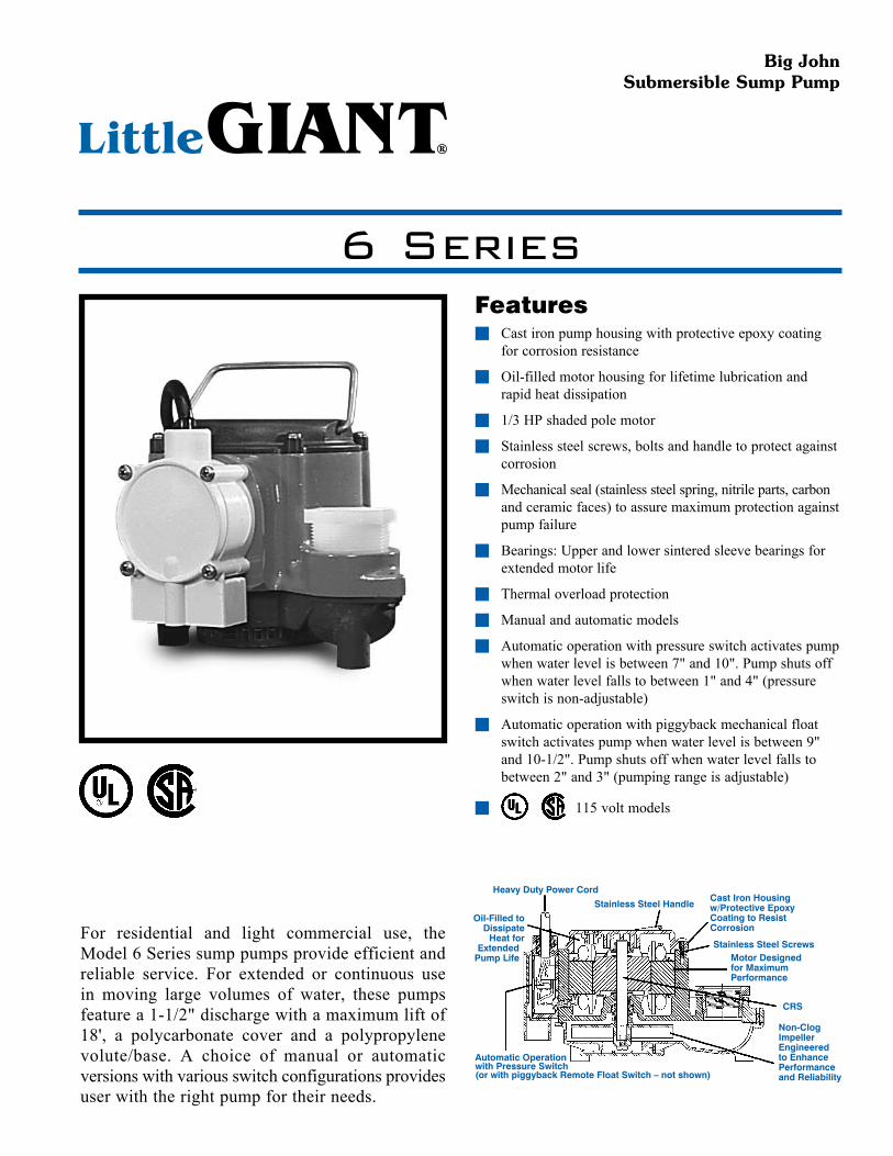
Heavy Duty Power Cord
Stainless Steel Handle
Stainless Steel ScrewsMotor Designedfor MaximumPerformance
Automatic Operationwith Pressure Switch(or with piggyback Remote Float Switch – not shown)
CRS
Non-Clog ImpellerEngineered to Enhance Performanceand Reliability
Cast Iron Housingw/Protective Epoxy Coating to Resist Corrosion
Oil-Filled toDissipate
Heat forExtended
Pump Life
Featuresn Castironpumphousingwithprotectiveepoxycoating
forcorrosionresistance
n Oil-filledmotorhousingforlifetimelubricationandrapidheatdissipation
n 1/3HPshadedpolemotor
n Stainlesssteelscrews,boltsandhandletoprotectagainstcorrosion
n Mechanicalseal(stainlesssteelspring,nitrileparts,carbonandceramicfaces)toassuremaximumprotectionagainstpumpfailure
n Bearings:Upperandlowersinteredsleevebearingsforextendedmotorlife
n Thermaloverloadprotection
n Manualandautomaticmodels
n Automaticoperationwithpressureswitchactivatespumpwhenwaterlevelisbetween7"and10".Pumpshutsoffwhenwaterlevelfallstobetween1"and4"(pressureswitchisnon-adjustable)
n Automaticoperationwithpiggybackmechanicalfloatswitchactivatespumpwhenwaterlevelisbetween9"and10-1/2".Pumpshutsoffwhenwaterlevelfallstobetween2"and3"(pumpingrangeisadjustable)
n 115voltmodels
Big John Submersible Sump Pump
For residential and light commercial use, theModel6Seriessumppumpsprovideefficientandreliable service. For extended or continuous usein moving large volumes of water, these pumpsfeaturea1-1/2"dischargewithamaximumliftof18', a polycarbonate cover and a polypropylenevolute/base. A choice of manual or automaticversionswithvariousswitchconfigurationsprovidesuserwiththerightpumpfortheirneeds.
6 Series

Form 995201 — 09/2006www.LittleGiantPump.com
Specifications
6 Series
Construction
Model No.
Item No. Listing HP Volts
Amps R Watts
Flow (GPM @ Head) Shutoff Head (ft.) P.S.I.
Power Cord (ft.)
Weight (lbs.)
Dimensions (H x L x W) (in.)5' 10' 15'
6-CIM-R 506271 UL/CSA 1/3 115 9.0 720 46 29 12.5 18 7.8 10 16.50 7.25 x 9.50 x 7.256-CIM-R 506274 UL/CSA 1/3 115 9.0 720 46 29 12.5 18 7.8 25 18.00 7.25 x 9.50 x 7.25
6-CIA 506125 UL/CSA 1/3 115 9.0 720 46 29 12.5 18 7.8 25 18.50 6.00 x 9.50 x 8.506-CIA-RS* 506267 UL/CSA 1/3 115 9.0 720 46 29 12.5 18 7.8 10 17.50 7.25 x 9.50 x 7.25
6-CIM 506266 — 1/3 230 4.5 720 46 29 12.5 18 7.8 12 18.75 6.00 x 9.50 x 8.506-CIA 506158 UL/CSA 1/3 115 9.0 720 46 29 12.5 18 7.8 8 18.00 6.00 x 9.50 x 8.506-CIA 506168 UL/CSA 1/3 115 9.0 720 46 29 12.5 18 7.8 10 17.75 6.00 x 9.50 x 8.506-CIA 506166 — 1/3 230 4.5 720 46 29 12.5 18 7.8 8 18.50 6.00 x 9.50 x 8.50
6-CIA-RFS** 506171 UL/CSA 1/3 115 9.0 720 46 29 12.5 18 7.8 10 17.50 7.25 x 9.50 x 7.25All models are 60 Hz. CIM – Manual CIA – Automatic *Manual pump with RS-5 diaphragm switch included to convert to automatic operation.**Manual pump with piggyback mechanical float switch included for automatic operation.
Continuous Duty Rated — “Little Giant Wastewater pumps are rated continuous duty as long as they are run within the published ratings for these pumps.”
Cover Polycarbonate
Motor Housing Epoxy Coated Cast Iron
Impeller Material Nylon
Impeller Type Non-Clog
Volute Polypropylene
Power Cord 18/3 SJOW-A
Mechanical Shaft Seal Nitrile w/Carbon & Ceramic Faces
Fasteners Stainless Steel
Shaft Cold Rolled Steel
Bearings Upper: Sintered Iron/Copper, Flanged SleeveLower: Sintered Iron/Copper, Flanged Sleeve
POBox12010•OklahomaCity,OK73157Phone:800.701.7894•Fax:800.701.8046
E-mail:[email protected]
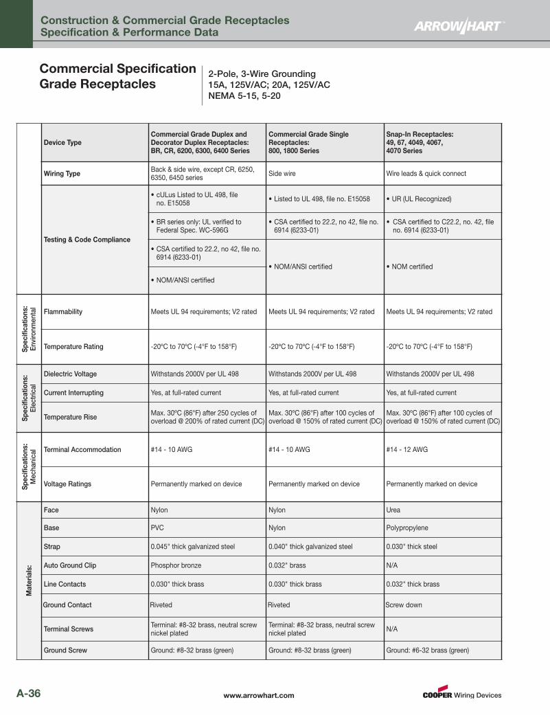
www.arrowhart.comA-36
Construction & Commercial Grade ReceptaclesSpecification & Performance Data
2-Pole, 3-Wire Grounding15A, 125V/AC; 20A, 125V/ACNEMA 5-15, 5-20
Commercial SpecificationGrade Receptacles
Device TypeCommercial Grade Duplex andDecorator Duplex Receptacles: BR, CR, 6200, 6300, 6400 Series
Commercial Grade SingleReceptacles: 800, 1800 Series
Snap-In Receptacles: 49, 67, 4049, 4067, 4070 Series
Wiring Type Back & side wire, except CR, 6250,6350, 6450 series Side wire Wire leads & quick connect
Testing & Code Compliance
• cULus Listed to UL 498, fileno. E15058 • Listed to UL 498, file no. E15058 • UR (UL Recognized)
• BR series only: UL verified toFederal Spec. WC-596G
• CSA certified to 22.2, no 42, file no. 6914 (6233-01)
• CSA certified to C22.2, no. 42, fileno. 6914 (6233-01)
• CSA certified to 22.2, no 42, file no. 6914 (6233-01)
• NOM/ANSI certified • NOM certified
• NOM/ANSI certified
Specifications:
Environmental
Flammability Meets UL 94 requirements; V2 rated Meets UL 94 requirements; V2 rated Meets UL 94 requirements; V2 rated
Temperature Rating -20ºC to 70ºC (-4°F to 158°F) -20ºC to 70ºC (-4°F to 158°F) -20ºC to 70ºC (-4°F to 158°F)
Specifications:
Electrical
Dielectric Voltage Withstands 2000V per UL 498 Withstands 2000V per UL 498 Withstands 2000V per UL 498
Current Interrupting Yes, at full-rated current Yes, at full-rated current Yes, at full-rated current
Temperature Rise Max. 30ºC (86°F) after 250 cycles ofoverload @ 200% of rated current (DC)
Max. 30ºC (86°F) after 100 cycles ofoverload @ 150% of rated current (DC)
Max. 30ºC (86°F) after 100 cycles ofoverload @ 150% of rated current (DC)
Specifications:
Mechanical Terminal Accommodation #14 - 10 AWG #14 - 10 AWG #14 - 12 AWG
Voltage Ratings Permanently marked on device Permanently marked on device Permanently marked on device
Materials:
Face Nylon Nylon Urea
Base PVC Nylon Polypropylene
Strap 0.045" thick galvanized steel 0.040" thick galvanized steel 0.030" thick steel
Auto Ground Clip Phosphor bronze 0.032" brass N/A
Line Contacts 0.030" thick brass 0.030" thick brass 0.032" thick brass
Ground Contact Riveted Riveted Screw down
Terminal Screws Terminal: #8-32 brass, neutral screwnickel plated
Terminal: #8-32 brass, neutral screwnickel plated N/A
Ground Screw Ground: #8-32 brass (green) Ground: #8-32 brass (green) Ground: #6-32 brass (green)

Catalog #
Project
Comments
Prepared by
Type
Date
SPECIFICATION FEATURES
02/15/2007 11:11:26 AMConsult your representative for additional options and finishes.
Specifications and Dimensions subject to change without notice. ADH061562
DIMENSIONS
DESCRIPTION
Lumark's Vaportight fixtures are designed for heavy-duty, non-corrosive environments. Applications include processing plants, cold storage, foundries, factories, loading docks and retail applications. U.L and CUL listed for non-classified wet locations. For use in 40°C ambient environments.
A ... HousingHousings and threaded guard are die-cast aluminum. Small housing utilizes 1/2" NPS entry while large housing use 3/4" NPS entry. Standard construction includes thru-way wiring for ceiling and wall mount units. Guard is one piece and features stainless steel locking screw for vandal resistance.
B ... GasketSilicone gasket provides long-life vapor seal.
C ... SocketSockets are medium-base, porcelain exterior with 150°C wire.
D ... GlobeGlobe is heat- and impact-resistant glass and accepts up to 200W incandescent in small housing and 300W incandescent in the large housing.
E ... MountingOptional pendant mount, wall or ceiling mounting. Wall mount fits 4" round or octagonal J-Box. Pendant mount utilizes 1/2" NPS for small and 3/4" NPS for large.
F ... FinishStandard finish is polyester powder coat grey.
ICVAPORTIGHT
200 - 300W
Incandescent
INDUSTRIAL
SAFETY AND SECURITY
LUMINAIRE
Wa dnePtnuoMll ant Mount Ceiling Mount
A
E
B
C
D
T E C H N I C A L D ATA40°C Ambient Environment IP65
S U P P LY W I R E R AT I N G S
75°C (ICVW1)90°C (ICVW2)90°C (ICVP1/ICVP2)90°C (ICVC1/ICVC2)
S H I P P I N G D ATA
Approximate Net Weight:
5 lbs. (2 kgs.)
1 5/8"[41mm]
Wa dnePtnuoM ll ant Mount Ce iling Mount
9 1/2" [242mm]10 9/16" [269mm]
Small12 5/8"
[321mm]Large14 1/4"
[362mm]
Small10 1/4"
[261mm]Large12 1/8"
[308mm]
Small9 3/4"
[248mm]Large11 1/2"
[293mm]
4 1/4" [108mm]5 11/16" [145mm]
4 1/4" [108mm]5 11/16" [145mm] S
YSTEMS
C
E R T I F I E
D
COOPER LIGHTING - LUMARK®
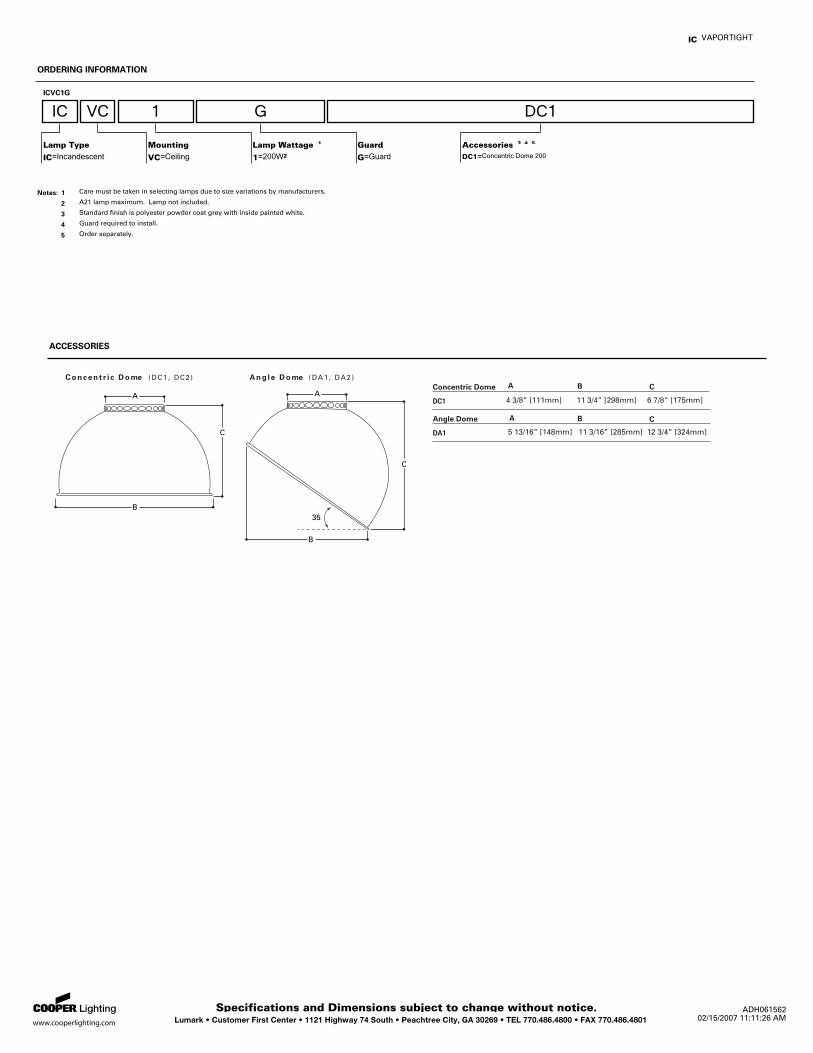
Lumark • Customer First Center • 1121 Highway 74 South • Peachtree City, GA 30269 • TEL 770.486.4800 • FAX 770.486.4801 02/15/2007 11:11:26 AMSpecifications and Dimensions subject to change without notice. ADH061562
ACCESSORIES
VAPORTIGHTIC
ORDERING INFORMATION
ICVC1G
IC VC 1 G DC1
Guard
G Guard=
Accessories 3, 4, 5
DC1 Concentric Dome 200=
Lamp Wattage 1
1 200W2=
Lamp Type
IC Incandescent=
Mounting
VC Ceiling=
1 Care must be taken in selecting lamps due to size variations by manufacturers.Notes:
2 A21 lamp maximum. Lamp not included.
3 Standard finish is polyester powder coat grey with inside painted white.
4 Guard required to install.
5 Order separately.
Concent r i c D ome ( DC 1 , DC2 ) Ang l e D ome (DA1 , DA2 )
B
A
C
B
A
C
35
Concentric Dome
DC1
Angle Dome
DA1
4 3/8” [111mm] 11 3/4” [298mm] 6 7/8” [175mm]
5 13/16” [148mm] 11 3/16” [285mm] 12 3/4” [324mm]
A B C
A B C
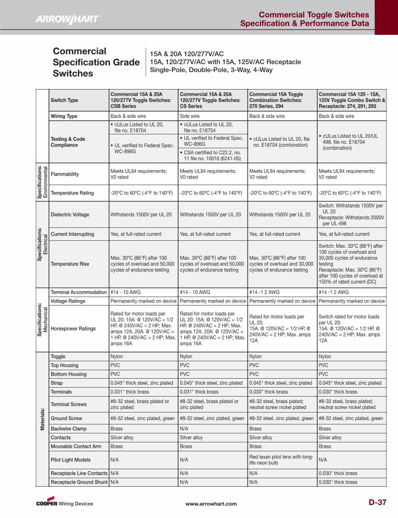
www.arrowhart.com D-37
Commercial Toggle Switches Specification & Performance Data
15A & 20A 120/277V/AC15A, 120/277V/AC with 15A, 125V/AC ReceptacleSingle-Pole, Double-Pole, 3-Way, 4-Way
CommercialSpecification GradeSwitches
Switch TypeCommercial 15A & 20A120/277V Toggle Switches:CSB Series
Commercial 15A & 20A120/277V Toggle Switches:CS Series
Commercial 15A ToggleCombination Switches: 270 Series, 294
Commercial 15A 120 - 15A,125V Toggle Combo Switch &Receptacle: 274, 291, 293
Wiring Type Back & side wire Side wire Back & side wire Back & side wire
Testing & CodeCompliance
• cULus Listed to UL 20, file no. E18704
• cULus Listed to UL 20, file no. E18704
• cULus Listed to UL 20, file no. E18704 (combination)
• cULus Listed to UL 20/UL498, file no. E18704(combination)• UL verified to Federal Spec.
WC-896G
• UL verified to Federal Spec.WC-896G
• CSA certified to C22.2, no.11 file no. 10016 (6241-05)
Specificatio
ns:
Environmental
Flammability Meets UL94 requirements;V0 rated
Meets UL94 requirements;V0 rated
Meets UL94 requirements;V2 rated
Meets UL94 requirements;V2 rated
Temperature Rating -20ºC to 60ºC (-4°F to 140°F) -20ºC to 60ºC (-4°F to 140°F) -20ºC to 60ºC (-4°F to 140°F) -20ºC to 60ºC (-4°F to 140°F)
Specificatio
ns:
Electrical
Dielectric Voltage Withstands 1500V per UL 20 Withstands 1500V per UL 20 Withstands 1500V per UL 20
Switch: Withstands 1500V per UL 20
Receptacle: Withstands 2000V per UL 498
Current Interrupting Yes, at full-rated current Yes, at full-rated current Yes, at full-rated current Yes, at full-rated current
Temperature RiseMax. 30ºC (86°F) after 100cycles of overload and 50,000cycles of endurance testing
Max. 30ºC (86°F) after 100cycles of overload and 50,000cycles of endurance testing
Max. 30ºC (86°F) after 100cycles of overload and 30,000cycles of endurance testing
Switch: Max. 30ºC (86°F) after100 cycles of overload and30,000 cycles of endurancetestingReceptacle: Max. 30ºC (86°F)after 100 cycles of overload at150% of rated current (DC)
Specificatio
ns:
Mechanical
Terminal Accommodation #14 - 10 AWG #14 - 10 AWG #14 -1 2 AWG #14 -1 2 AWG
Voltage Ratings Permanently marked on device Permanently marked on device Permanently marked on device Permanently marked on device
Horsepower Ratings
Rated for motor loads perUL 20: 15A: @ 120V/AC = 1/2HP, @ 240V/AC = 2 HP; Max.amps 12A. 20A: @ 120V/AC = 1 HP, @ 240V/AC = 2 HP; Max.amps 16A
Rated for motor loads perUL 20: 15A: @ 120V/AC = 1/2HP, @ 240V/AC = 2 HP; Max.amps 12A. 20A: @ 120V/AC = 1 HP, @ 240V/AC = 2 HP; Max.amps 16A
Rated for motor loads per UL 20: 15A: @ 120V/AC = 1/2 HP, @240V/AC = 2 HP; Max. amps12A
Switch rated for motor loadsper UL 20: 15A: @ 120V/AC = 1/2 HP, @240V/AC = 2 HP; Max. amps12A
Materials:
Toggle Nylon Nylon Nylon Nylon
Top Housing PVC PVC PVC PVC
Bottom Housing PVC PVC PVC PVC
Strap 0.045" thick steel, zinc plated 0.045" thick steel, zinc plated 0.045" thick steel, zinc plated 0.045" thick steel, zinc plated
Terminals 0.031" thick brass 0.031" thick brass 0.030" thick brass 0.030" thick brass
Terminal Screws #8-32 steel, brass plated orzinc plated
#8-32 steel, brass plated orzinc plated
#8-32 steel, brass plated;neutral screw nickel plated
#8-32 steel, brass plated;neutral screw nickel plated
Ground Screw #8-32 steel, zinc plated, green #8-32 steel, zinc plated, green #8-32 steel, zinc plated, green #8-32 steel, zinc plated, green
Backwire Clamp Brass N/A Brass Brass
Contacts Silver alloy Silver alloy Silver alloy Silver alloy
Moveable Contact Arm Brass Brass Brass Brass
Pilot Light Models N/A N/A Red lexan pilot lens with long-life neon bulb N/A
Receptacle Line Contacts N/A N/A N/A 0.030" thick brass
Receptacle Ground Shunt N/A N/A N/A 0.030" thick brass