Embed Size (px)
Citation preview
Product CatalogueBulk Conveyors - Fluidization cones - Unloaders - Bag emptiers - Compactors
Valves - Mixers - Signal & Indication - Transport detailsSaftey valves - Rotary valves
Pneumatic conveying systems
PNEUMATIC CONVEYORS
Web: www.scanmatic.se Phone: +46 42 504 25 Fax: +46 42 515 71
SCANMATIC BULK CONVEYOR
Pneumatic bulk gods transport
The solid and elegant solution for bulk goods handling
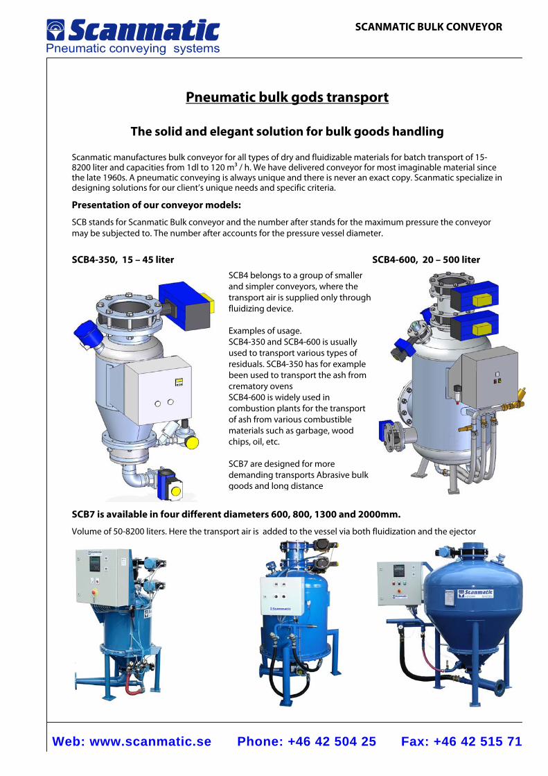
Scanmatic manufactures bulk conveyor for all types of dry and fluidizable materials for batch transport of 15-8200 liter and capacities from 1dl to 120 m3 / h. We have delivered conveyor for most imaginable material since the late 1960s. A pneumatic conveying is always unique and there is never an exact copy. Scanmatic specialize in designing solutions for our client’s unique needs and specific criteria.
Presentation of our conveyor models:
SCB stands for Scanmatic Bulk conveyor and the number after stands for the maximum pressure the conveyor may be subjected to. The number after accounts for the pressure vessel diameter.
SCB4-350, 15 – 45 liter SCB4-600, 20 – 500 liter
SCB7 is available in four different diameters 600, 800, 1300 and 2000mm.
Volume of 50-8200 liters. Here the transport air is added to the vessel via both fluidization and the ejector utloppet.
SCB4 belongs to a group of smaller and simpler conveyors, where the transport air is supplied only through fluidizing device. Examples of usage. SCB4-350 and SCB4-600 is usually used to transport various types of residuals. SCB4-350 has for example been used to transport the ash from crematory ovens SCB4-600 is widely used in combustion plants for the transport of ash from various combustible materials such as garbage, wood chips, oil, etc. SCB7 are designed for more demanding transports Abrasive bulk goods and long distance
Web: www.scanmatic.se Phone: +46 42 504 25 Fax: +46 42 515 71
SCANMATIC BULK CONVEYOR
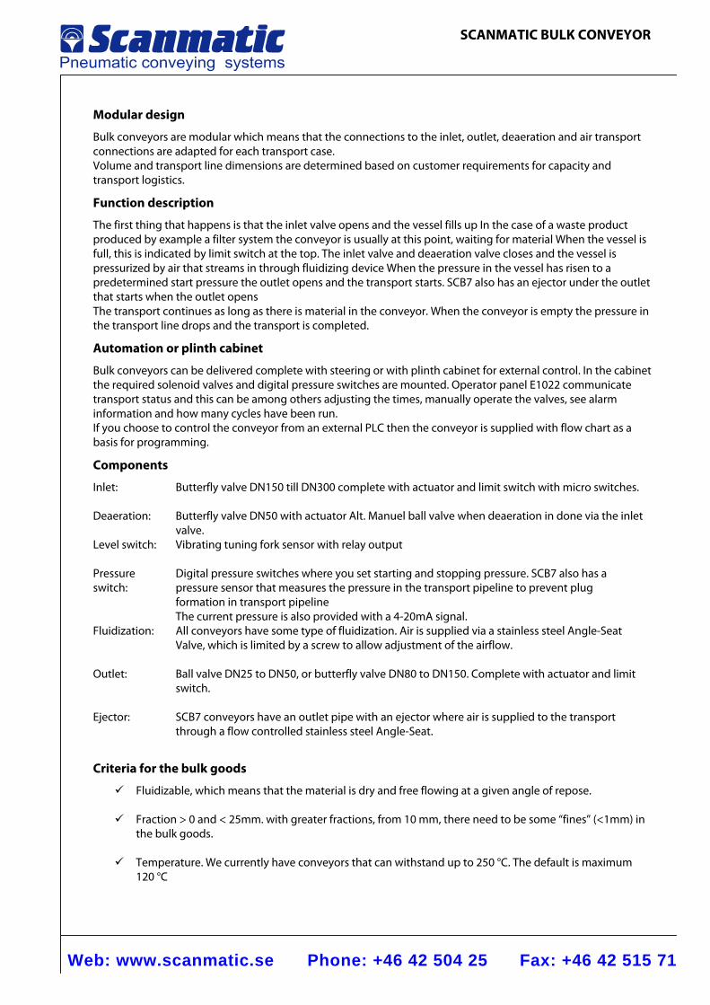
Modular design
Bulk conveyors are modular which means that the connections to the inlet, outlet, deaeration and air transport connections are adapted for each transport case. Volume and transport line dimensions are determined based on customer requirements for capacity and transport logistics.
Function description
The first thing that happens is that the inlet valve opens and the vessel fills up In the case of a waste product produced by example a filter system the conveyor is usually at this point, waiting for material When the vessel is full, this is indicated by limit switch at the top. The inlet valve and deaeration valve closes and the vessel is pressurized by air that streams in through fluidizing device When the pressure in the vessel has risen to a predetermined start pressure the outlet opens and the transport starts. SCB7 also has an ejector under the outlet that starts when the outlet opens The transport continues as long as there is material in the conveyor. When the conveyor is empty the pressure in the transport line drops and the transport is completed.
Automation or plinth cabinet
Bulk conveyors can be delivered complete with steering or with plinth cabinet for external control. In the cabinet the required solenoid valves and digital pressure switches are mounted. Operator panel E1022 communicate transport status and this can be among others adjusting the times, manually operate the valves, see alarm information and how many cycles have been run. If you choose to control the conveyor from an external PLC then the conveyor is supplied with flow chart as a basis for programming.
Components
Inlet:
Butterfly valve DN150 till DN300 complete with actuator and limit switch with micro switches.
Deaeration:
Butterfly valve DN50 with actuator Alt. Manuel ball valve when deaeration in done via the inlet valve.
Level switch:
Vibrating tuning fork sensor with relay output
Pressure switch:
Digital pressure switches where you set starting and stopping pressure. SCB7 also has a pressure sensor that measures the pressure in the transport pipeline to prevent plug formation in transport pipeline The current pressure is also provided with a 4-20mA signal.
Fluidization:
All conveyors have some type of fluidization. Air is supplied via a stainless steel Angle-Seat Valve, which is limited by a screw to allow adjustment of the airflow.
Outlet:
Ball valve DN25 to DN50, or butterfly valve DN80 to DN150. Complete with actuator and limit switch.
Ejector: SCB7 conveyors have an outlet pipe with an ejector where air is supplied to the transport through a flow controlled stainless steel Angle-Seat.
Criteria for the bulk goods
Fluidizable, which means that the material is dry and free flowing at a given angle of repose.
Fraction > 0 and < 25mm. with greater fractions, from 10 mm, there need to be some “fines” (<1mm) in the bulk goods.
Temperature. We currently have conveyors that can withstand up to 250 °C. The default is maximum
120 °C
Web: www.scanmatic.se Phone: +46 42 504 25 Fax: +46 42 515 71
BULK CONVEYOR SCB4-350 TS01-001
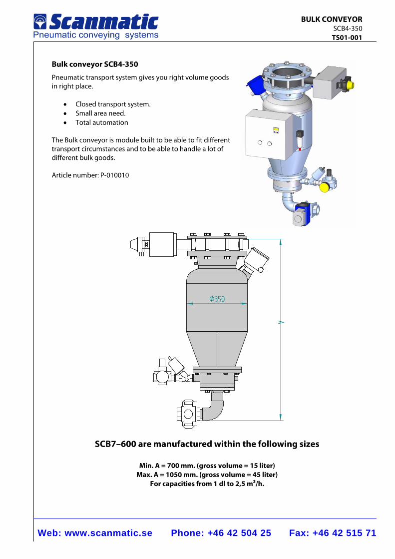
Bulk conveyor SCB4-350
Pneumatic transport system gives you right volume goods in right place.
• Closed transport system. • Small area need. • Total automation
The Bulk conveyor is module built to be able to fit different transport circumstances and to be able to handle a lot of different bulk goods. Article number: P-010010
Ø350
A
SCB7–600 are manufactured within the following sizes
Min. A = 700 mm. (gross volume = 15 liter) Max. A = 1050 mm. (gross volume = 45 liter)
For capacities from 1 dl to 2,5 m3/h.
Web: www.scanmatic.se Phone: +46 42 504 25 Fax: +46 42 515 71
BULK CONVEYOR SCB4-350 TS01-001
5
6
1
3
2
10
4
98
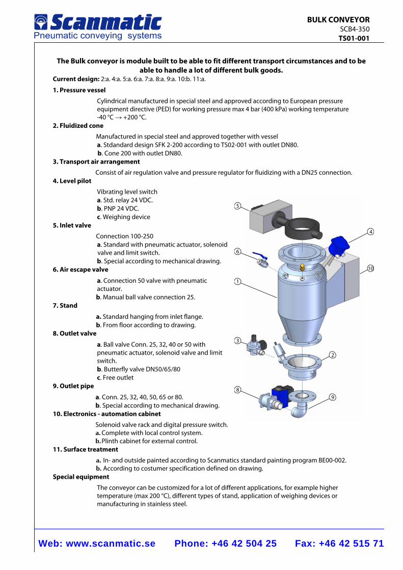
The Bulk conveyor is module built to be able to fit different transport circumstances and to be able to handle a lot of different bulk goods.
Current design: 2:a. 4:a. 5:a. 6:a. 7:a. 8:a. 9:a. 10:b. 11:a.
1. Pressure vessel
Cylindrical manufactured in special steel and approved according to European pressure equipment directive (PED) for working pressure max 4 bar (400 kPa) working temperature -40 °C → +200 °C.
2. Fluidized cone
Manufactured in special steel and approved together with vessel a. Stdandard design SFK 2-200 according to TS02-001 with outlet DN80. b. Cone 200 with outlet DN80.
3. Transport air arrangement
Consist of air regulation valve and pressure regulator for fluidizing with a DN25 connection. 4. Level pilot
Vibrating level switch a. Std. relay 24 VDC. b. PNP 24 VDC. c. Weighing device
5. Inlet valve
Connection 100-250 a. Standard with pneumatic actuator, solenoid valve and limit switch. b. Special according to mechanical drawing.
6. Air escape valve
a. Connection 50 valve with pneumatic actuator.
b. Manual ball valve connection 25. 7. Stand
a. Standard hanging from inlet flange. b. From floor according to drawing. 8. Outlet valve
a. Ball valve Conn. 25, 32, 40 or 50 with pneumatic actuator, solenoid valve and limit switch. b. Butterfly valve DN50/65/80 c. Free outlet
9. Outlet pipe
a. Conn. 25, 32, 40, 50, 65 or 80. b. Special according to mechanical drawing.
10. Electronics - automation cabinet
Solenoid valve rack and digital pressure switch. a. Complete with local control system. b. Plinth cabinet for external control.
11. Surface treatment
a. In- and outside painted according to Scanmatics standard painting program BE00-002. b. According to costumer specification defined on drawing.
Special equipment
The conveyor can be customized for a lot of different applications, for example higher temperature (max 200 °C), different types of stand, application of weighing devices or manufacturing in stainless steel.
Web: www.scanmatic.se Phone: +46 42 504 25 Fax: +46 42 515 71
BULK CONVEYOR SCB4-600 TS01-002
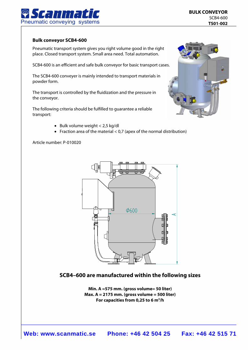
Bulk conveyor SCB4-600
Pneumatic transport system gives you right volume good in the right place. Closed transport system. Small area need. Total automation. SCB4-600 is an efficient and safe bulk conveyor for basic transport cases. The SCB4-600 conveyer is mainly intended to transport materials in powder form. The transport is controlled by the fluidization and the pressure in the conveyor. The following criteria should be fulfilled to guarantee a reliable transport:
• Bulk volume weight < 2,5 kg/dl • Fraction area of the material < 0,7 (apex of the normal distribution)
Article number: P-010020
AØ600
SCB4–600 are manufactured within the following sizes
Min. A =575 mm. (gross volume= 50 liter) Max. A = 2175 mm. (gross volume = 500 liter)
For capacities from 0,25 to 6 m3/h
Web: www.scanmatic.se Phone: +46 42 504 25 Fax: +46 42 515 71
BULK CONVEYOR SCB4-600 TS01-002
1
2
3 4
5
6
8
7
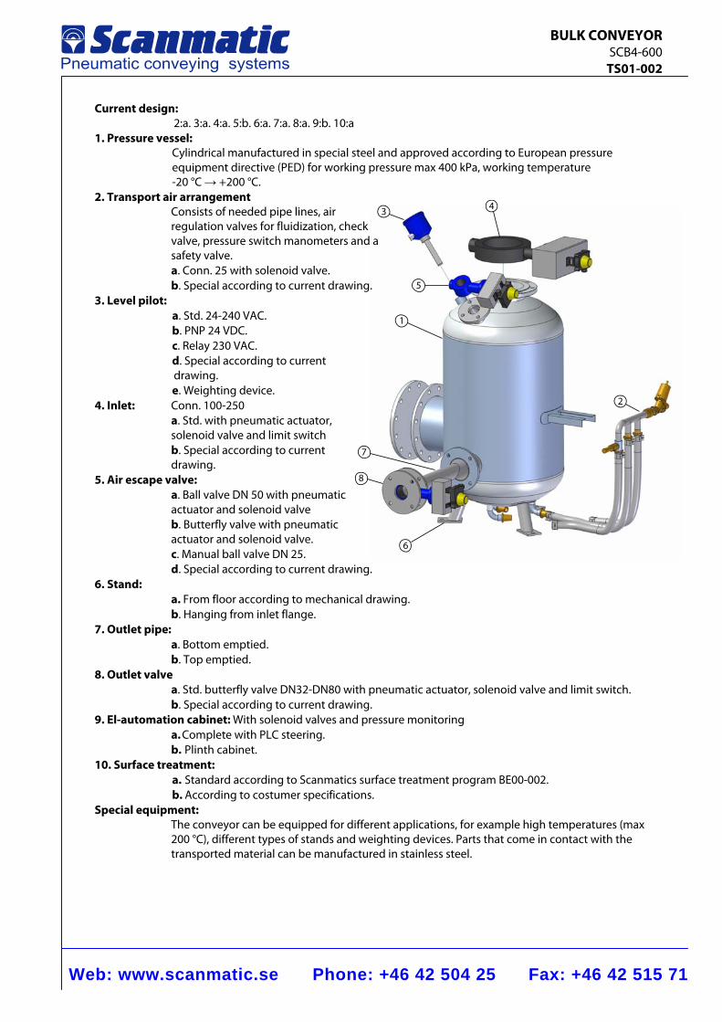
Current design: 2:a. 3:a. 4:a. 5:b. 6:a. 7:a. 8:a. 9:b. 10:a
1. Pressure vessel: Cylindrical manufactured in special steel and approved according to European pressure equipment directive (PED) for working pressure max 400 kPa, working temperature -20 °C → +200 °C.
2. Transport air arrangement Consists of needed pipe lines, air regulation valves for fluidization, check valve, pressure switch manometers and a safety valve. a. Conn. 25 with solenoid valve. b. Special according to current drawing.
3. Level pilot: a. Std. 24-240 VAC. b. PNP 24 VDC. c. Relay 230 VAC. d. Special according to current
drawing. e. Weighting device.
4. Inlet: Conn. 100-250 a. Std. with pneumatic actuator, solenoid valve and limit switch b. Special according to current drawing.
5. Air escape valve: a. Ball valve DN 50 with pneumatic actuator and solenoid valve b. Butterfly valve with pneumatic actuator and solenoid valve. c. Manual ball valve DN 25. d. Special according to current drawing.
6. Stand: a. From floor according to mechanical drawing. b. Hanging from inlet flange.
7. Outlet pipe: a. Bottom emptied.
b. Top emptied. 8. Outlet valve a. Std. butterfly valve DN32-DN80 with pneumatic actuator, solenoid valve and limit switch.
b. Special according to current drawing. 9. El-automation cabinet: With solenoid valves and pressure monitoring
a. Complete with PLC steering. b. Plinth cabinet.
10. Surface treatment: a. Standard according to Scanmatics surface treatment program BE00-002. b. According to costumer specifications.
Special equipment: The conveyor can be equipped for different applications, for example high temperatures (max 200 °C), different types of stands and weighting devices. Parts that come in contact with the transported material can be manufactured in stainless steel.
Web: www.scanmatic.se Phone: +46 42 504 25 Fax: +46 42 515 71
BULK CONVEYOR SCB7-600 TS01-003
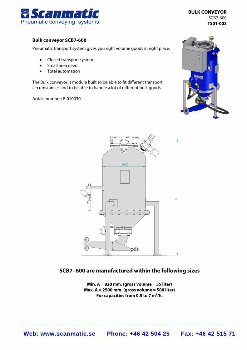
Bulk conveyor SCB7-600
Pneumatic transport system gives you right volume goods in right place.
• Closed transport system. • Small area need. • Total automation
The Bulk conveyor is module built to be able to fit different transport circumstances and to be able to handle a lot of different bulk goods. Article number: P-010030
A
Ø600
SCB7–600 are manufactured within the following sizes
Min. A = 820 mm. (gross volume = 55 liter) Max. A = 2500 mm. (gross volume = 500 liter)
For capacities from 0,5 to 7 m3/h.
Web: www.scanmatic.se Phone: +46 42 504 25 Fax: +46 42 515 71
BULK CONVEYOR SCB7-600 TS01-003
1
3
4
5
6
7
9
8
2
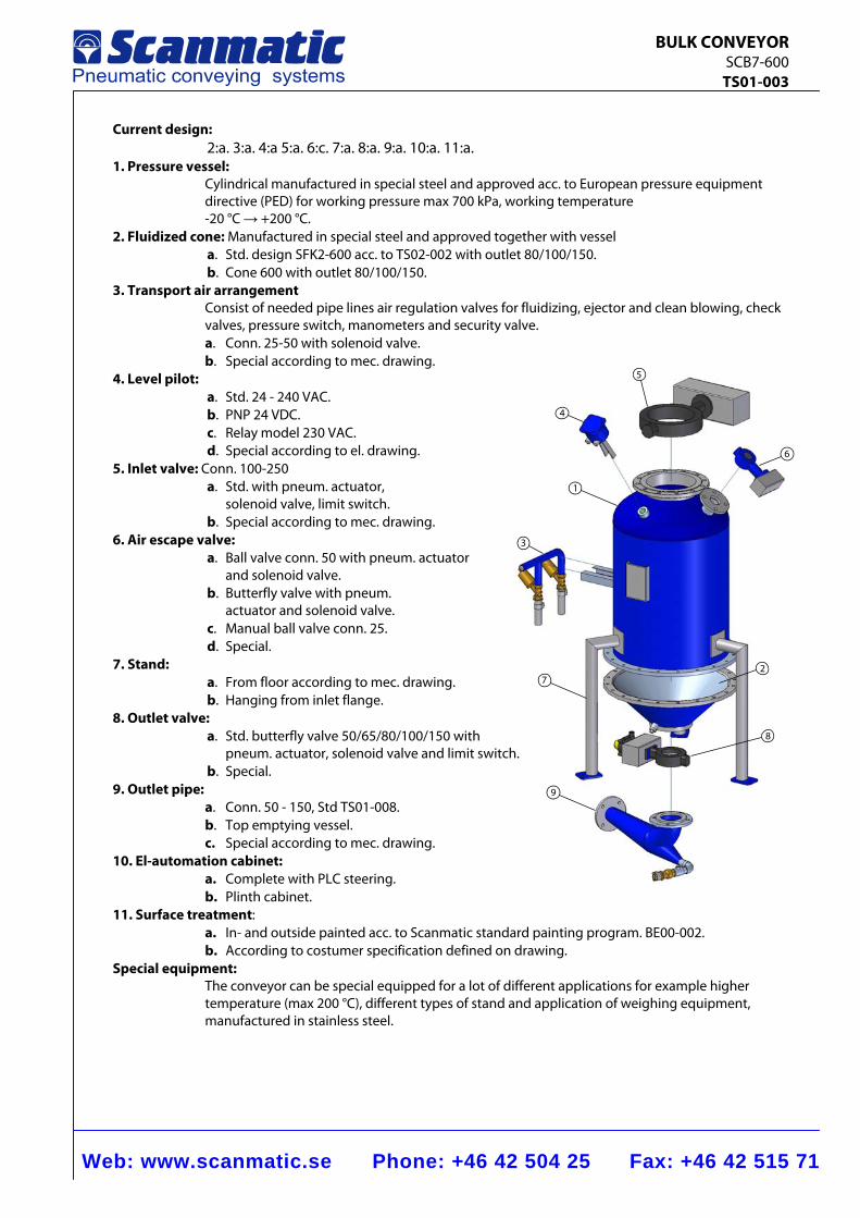
Current design: 2:a. 3:a. 4:a 5:a. 6:c. 7:a. 8:a. 9:a. 10:a. 11:a.
1. Pressure vessel: Cylindrical manufactured in special steel and approved acc. to European pressure equipment directive (PED) for working pressure max 700 kPa, working temperature -20 °C → +200 °C.
2. Fluidized cone: Manufactured in special steel and approved together with vessel a. Std. design SFK2-600 acc. to TS02-002 with outlet 80/100/150. b. Cone 600 with outlet 80/100/150.
3. Transport air arrangement Consist of needed pipe lines air regulation valves for fluidizing, ejector and clean blowing, check valves, pressure switch, manometers and security valve. a. Conn. 25-50 with solenoid valve. b. Special according to mec. drawing.
4. Level pilot: a. Std. 24 - 240 VAC. b. PNP 24 VDC. c. Relay model 230 VAC. d. Special according to el. drawing.
5. Inlet valve: Conn. 100-250 a. Std. with pneum. actuator,
solenoid valve, limit switch. b. Special according to mec. drawing.
6. Air escape valve: a. Ball valve conn. 50 with pneum. actuator
and solenoid valve. b. Butterfly valve with pneum.
actuator and solenoid valve. c. Manual ball valve conn. 25. d. Special.
7. Stand: a. From floor according to mec. drawing. b. Hanging from inlet flange.
8. Outlet valve: a. Std. butterfly valve 50/65/80/100/150 with pneum. actuator, solenoid valve and limit switch. b. Special.
9. Outlet pipe: a. Conn. 50 - 150, Std TS01-008. b. Top emptying vessel. c. Special according to mec. drawing.
10. El-automation cabinet: a. Complete with PLC steering. b. Plinth cabinet.
11. Surface treatment: a. In- and outside painted acc. to Scanmatic standard painting program. BE00-002. b. According to costumer specification defined on drawing.
Special equipment: The conveyor can be special equipped for a lot of different applications for example higher temperature (max 200 °C), different types of stand and application of weighing equipment, manufactured in stainless steel.
Web: www.scanmatic.se Phone: +46 42 504 25 Fax: +46 42 515 71
BULK CONVEYOR SCB7-800 TS01-004
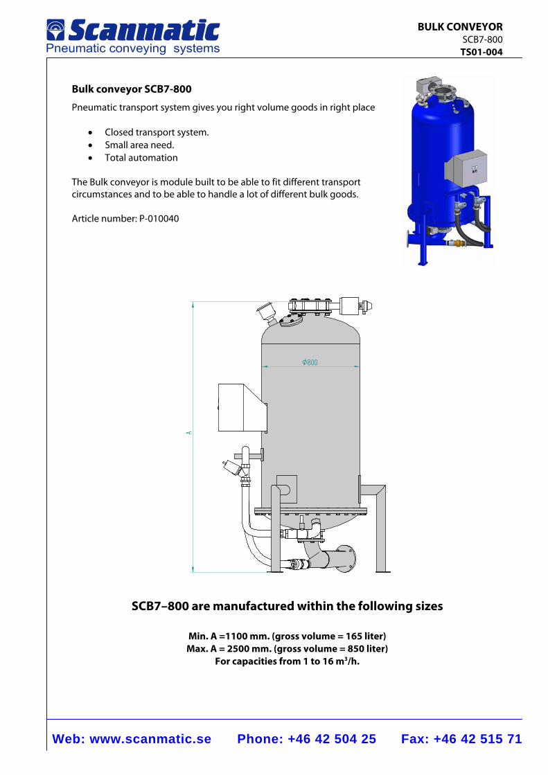
Bulk conveyor SCB7-800
Pneumatic transport system gives you right volume goods in right place
• Closed transport system. • Small area need. • Total automation
The Bulk conveyor is module built to be able to fit different transport circumstances and to be able to handle a lot of different bulk goods.
Article number: P-010040
A
Ø800
SCB7–800 are manufactured within the following sizes
Min. A =1100 mm. (gross volume = 165 liter) Max. A = 2500 mm. (gross volume = 850 liter)
For capacities from 1 to 16 m3/h.
Web: www.scanmatic.se Phone: +46 42 504 25 Fax: +46 42 515 71
BULK CONVEYOR SCB7-800 TS01-004
1
3
4
5
6
7
9
8
2
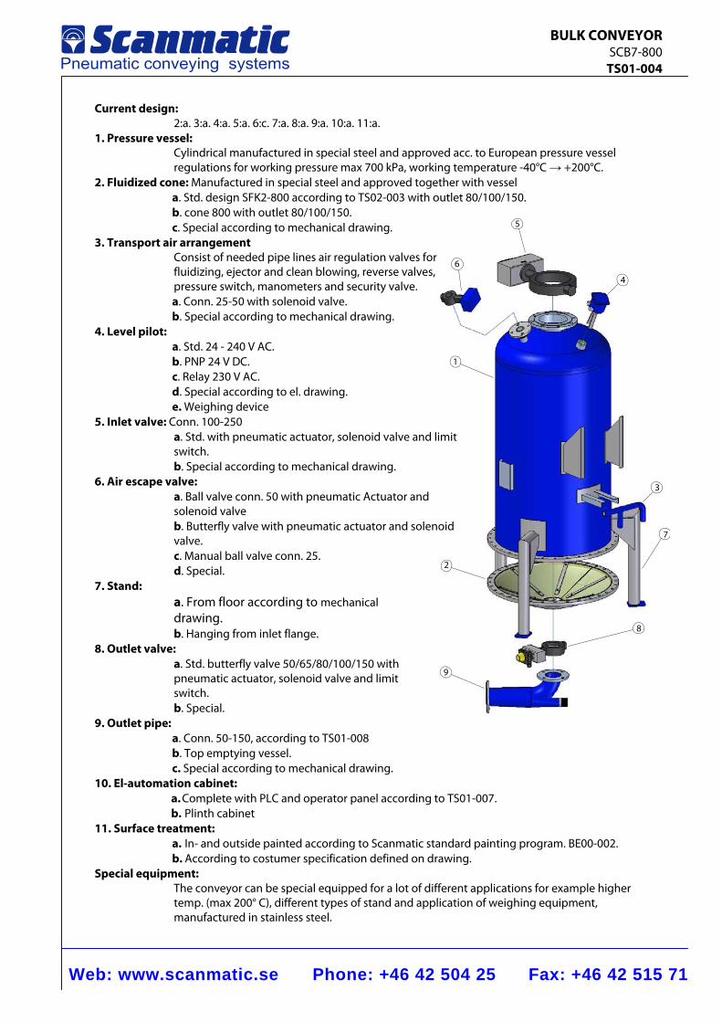
Current design: 2:a. 3:a. 4:a. 5:a. 6:c. 7:a. 8:a. 9:a. 10:a. 11:a.
1. Pressure vessel: Cylindrical manufactured in special steel and approved acc. to European pressure vessel regulations for working pressure max 700 kPa, working temperature -40°C → +200°C.
2. Fluidized cone: Manufactured in special steel and approved together with vessel a. Std. design SFK2-800 according to TS02-003 with outlet 80/100/150. b. cone 800 with outlet 80/100/150. c. Special according to mechanical drawing.
3. Transport air arrangement Consist of needed pipe lines air regulation valves for fluidizing, ejector and clean blowing, reverse valves, pressure switch, manometers and security valve. a. Conn. 25-50 with solenoid valve. b. Special according to mechanical drawing.
4. Level pilot: a. Std. 24 - 240 V AC. b. PNP 24 V DC. c. Relay 230 V AC. d. Special according to el. drawing. e. Weighing device
5. Inlet valve: Conn. 100-250 a. Std. with pneumatic actuator, solenoid valve and limit switch. b. Special according to mechanical drawing.
6. Air escape valve: a. Ball valve conn. 50 with pneumatic Actuator and solenoid valve b. Butterfly valve with pneumatic actuator and solenoid valve. c. Manual ball valve conn. 25. d. Special.
7. Stand: a. From floor according to mechanical drawing. b. Hanging from inlet flange.
8. Outlet valve: a. Std. butterfly valve 50/65/80/100/150 with pneumatic actuator, solenoid valve and limit switch. b. Special.
9. Outlet pipe: a. Conn. 50-150, according to TS01-008 b. Top emptying vessel. c. Special according to mechanical drawing.
10. El-automation cabinet: a. Complete with PLC and operator panel according to TS01-007. b. Plinth cabinet
11. Surface treatment: a. In- and outside painted according to Scanmatic standard painting program. BE00-002. b. According to costumer specification defined on drawing.
Special equipment: The conveyor can be special equipped for a lot of different applications for example higher temp. (max 200° C), different types of stand and application of weighing equipment, manufactured in stainless steel.
Web: www.scanmatic.se Phone: +46 42 504 25 Fax: +46 42 515 71
BULK CONVEYOR SCB7-1300 TS01-005
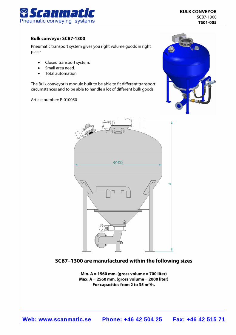
Bulk conveyor SCB7-1300
Pneumatic transport system gives you right volume goods in right place
• Closed transport system. • Small area need. • Total automation
The Bulk conveyor is module built to be able to fit different transport circumstances and to be able to handle a lot of different bulk goods. Article number: P-010050
A
Ø1300
SCB7–1300 are manufactured within the following sizes
Min. A = 1560 mm. (gross volume = 700 liter) Max. A = 2560 mm. (gross volume = 2000 liter)
For capacities from 2 to 35 m3/h.
Web: www.scanmatic.se Phone: +46 42 504 25 Fax: +46 42 515 71
BULK CONVEYOR SCB7-1300 TS01-005
1
3
4
5
6
7
98
2
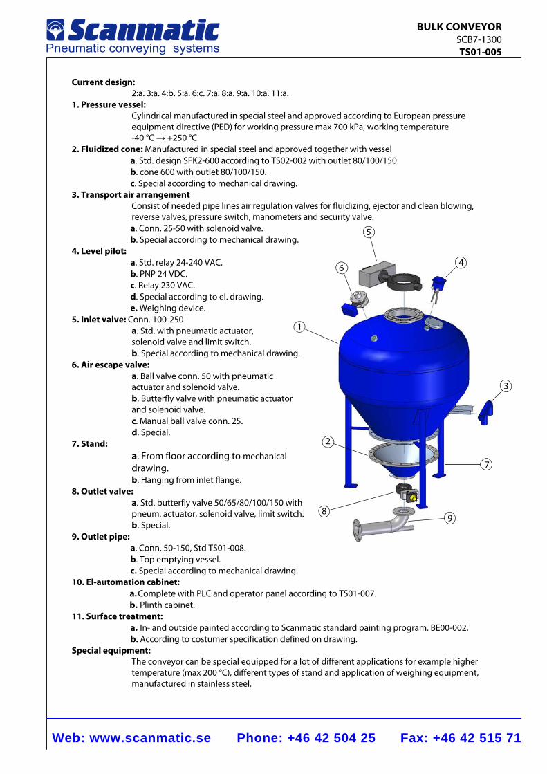
Current design: 2:a. 3:a. 4:b. 5:a. 6:c. 7:a. 8:a. 9:a. 10:a. 11:a.
1. Pressure vessel: Cylindrical manufactured in special steel and approved according to European pressure equipment directive (PED) for working pressure max 700 kPa, working temperature -40 °C → +250 °C.
2. Fluidized cone: Manufactured in special steel and approved together with vessel a. Std. design SFK2-600 according to TS02-002 with outlet 80/100/150. b. cone 600 with outlet 80/100/150. c. Special according to mechanical drawing.
3. Transport air arrangement Consist of needed pipe lines air regulation valves for fluidizing, ejector and clean blowing, reverse valves, pressure switch, manometers and security valve. a. Conn. 25-50 with solenoid valve. b. Special according to mechanical drawing.
4. Level pilot: a. Std. relay 24-240 VAC. b. PNP 24 VDC. c. Relay 230 VAC. d. Special according to el. drawing. e. Weighing device.
5. Inlet valve: Conn. 100-250 a. Std. with pneumatic actuator, solenoid valve and limit switch. b. Special according to mechanical drawing.
6. Air escape valve: a. Ball valve conn. 50 with pneumatic actuator and solenoid valve. b. Butterfly valve with pneumatic actuator and solenoid valve. c. Manual ball valve conn. 25. d. Special.
7. Stand: a. From floor according to mechanical drawing. b. Hanging from inlet flange.
8. Outlet valve: a. Std. butterfly valve 50/65/80/100/150 with pneum. actuator, solenoid valve, limit switch. b. Special.
9. Outlet pipe: a. Conn. 50-150, Std TS01-008. b. Top emptying vessel. c. Special according to mechanical drawing.
10. El-automation cabinet: a. Complete with PLC and operator panel according to TS01-007. b. Plinth cabinet.
11. Surface treatment: a. In- and outside painted according to Scanmatic standard painting program. BE00-002. b. According to costumer specification defined on drawing.
Special equipment: The conveyor can be special equipped for a lot of different applications for example higher temperature (max 200 °C), different types of stand and application of weighing equipment, manufactured in stainless steel.
Web: www.scanmatic.se Phone: +46 42 504 25 Fax: +46 42 515 71
BULK CONVEYOR SCB7-2000 TS01-006
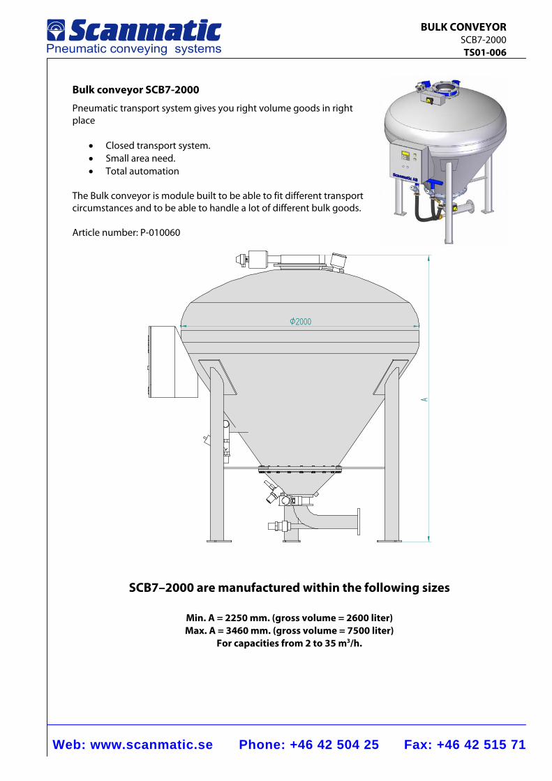
Bulk conveyor SCB7-2000
Pneumatic transport system gives you right volume goods in right place
• Closed transport system. • Small area need. • Total automation
The Bulk conveyor is module built to be able to fit different transport circumstances and to be able to handle a lot of different bulk goods.
Article number: P-010060
A
Ø2000
SCB7–2000 are manufactured within the following sizes
Min. A = 2250 mm. (gross volume = 2600 liter) Max. A = 3460 mm. (gross volume = 7500 liter)
For capacities from 2 to 35 m3/h.
Web: www.scanmatic.se Phone: +46 42 504 25 Fax: +46 42 515 71
BULK CONVEYOR SCB7-2000 TS01-006
1
3
45
6
7
98
2
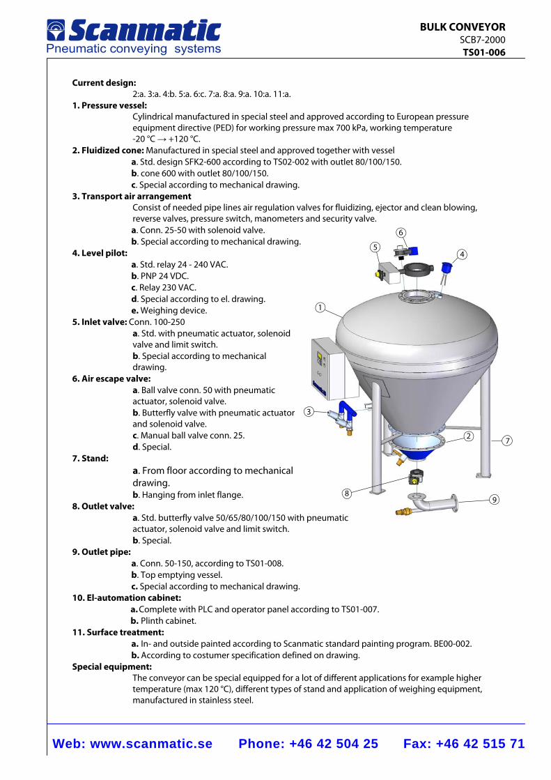
Current design: 2:a. 3:a. 4:b. 5:a. 6:c. 7:a. 8:a. 9:a. 10:a. 11:a.
1. Pressure vessel: Cylindrical manufactured in special steel and approved according to European pressure equipment directive (PED) for working pressure max 700 kPa, working temperature -20 °C → +120 °C.
2. Fluidized cone: Manufactured in special steel and approved together with vessel a. Std. design SFK2-600 according to TS02-002 with outlet 80/100/150. b. cone 600 with outlet 80/100/150. c. Special according to mechanical drawing.
3. Transport air arrangement Consist of needed pipe lines air regulation valves for fluidizing, ejector and clean blowing, reverse valves, pressure switch, manometers and security valve. a. Conn. 25-50 with solenoid valve. b. Special according to mechanical drawing.
4. Level pilot: a. Std. relay 24 - 240 VAC. b. PNP 24 VDC. c. Relay 230 VAC. d. Special according to el. drawing. e. Weighing device.
5. Inlet valve: Conn. 100-250 a. Std. with pneumatic actuator, solenoid valve and limit switch. b. Special according to mechanical
drawing. 6. Air escape valve:
a. Ball valve conn. 50 with pneumatic actuator, solenoid valve. b. Butterfly valve with pneumatic actuator and solenoid valve. c. Manual ball valve conn. 25. d. Special.
7. Stand: a. From floor according to mechanical drawing. b. Hanging from inlet flange.
8. Outlet valve: a. Std. butterfly valve 50/65/80/100/150 with pneumatic actuator, solenoid valve and limit switch. b. Special.
9. Outlet pipe: a. Conn. 50-150, according to TS01-008. b. Top emptying vessel. c. Special according to mechanical drawing.
10. El-automation cabinet: a. Complete with PLC and operator panel according to TS01-007. b. Plinth cabinet.
11. Surface treatment: a. In- and outside painted according to Scanmatic standard painting program. BE00-002. b. According to costumer specification defined on drawing.
Special equipment: The conveyor can be special equipped for a lot of different applications for example higher temperature (max 120 °C), different types of stand and application of weighing equipment, manufactured in stainless steel.
Web: www.scanmatic.se Phone: +46 42 504 25 Fax: +46 42 515 71
BULK CONVEYOR SCB10-600 TS01-010
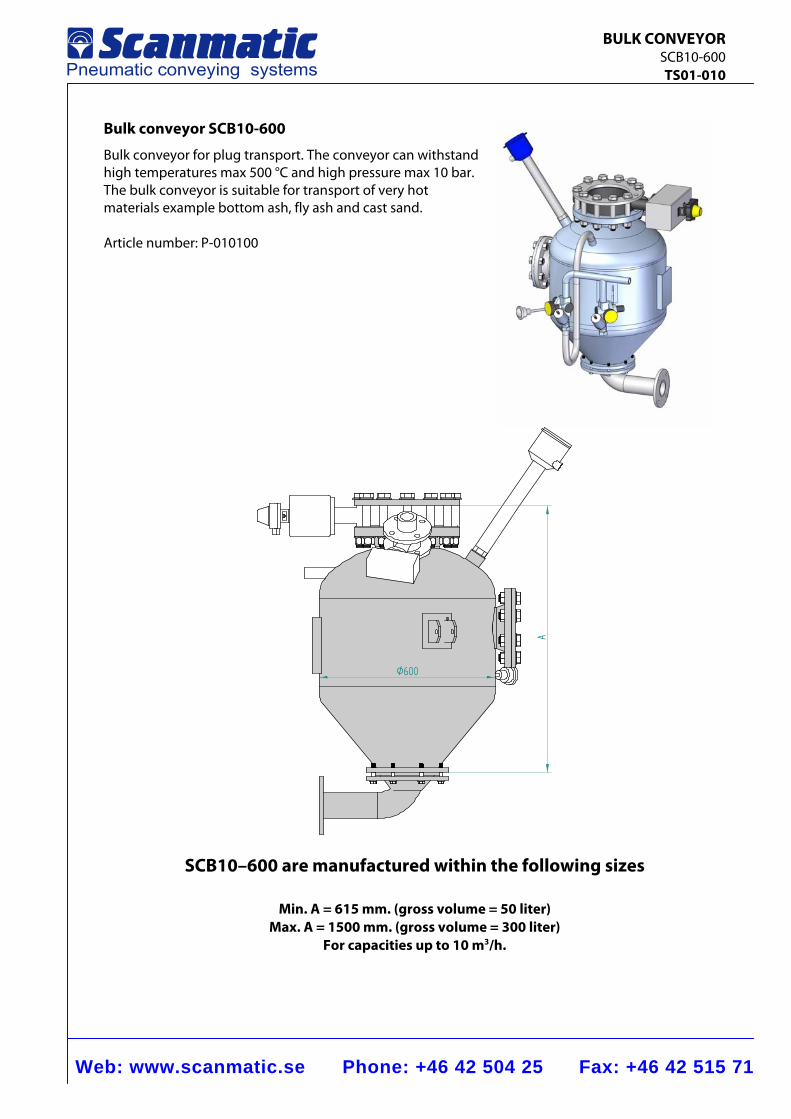
Bulk conveyor SCB10-600
Bulk conveyor for plug transport. The conveyor can withstand high temperatures max 500 °C and high pressure max 10 bar. The bulk conveyor is suitable for transport of very hot materials example bottom ash, fly ash and cast sand. Article number: P-010100
Ø600
A
SCB10–600 are manufactured within the following sizes
Min. A = 615 mm. (gross volume = 50 liter) Max. A = 1500 mm. (gross volume = 300 liter)
For capacities up to 10 m3/h.
Web: www.scanmatic.se Phone: +46 42 504 25 Fax: +46 42 515 71
BULK CONVEYOR SCB10-600 TS01-010
5
3
7
1 9c
9d
9a
2a
2b
9b
13
4 6
11
9e
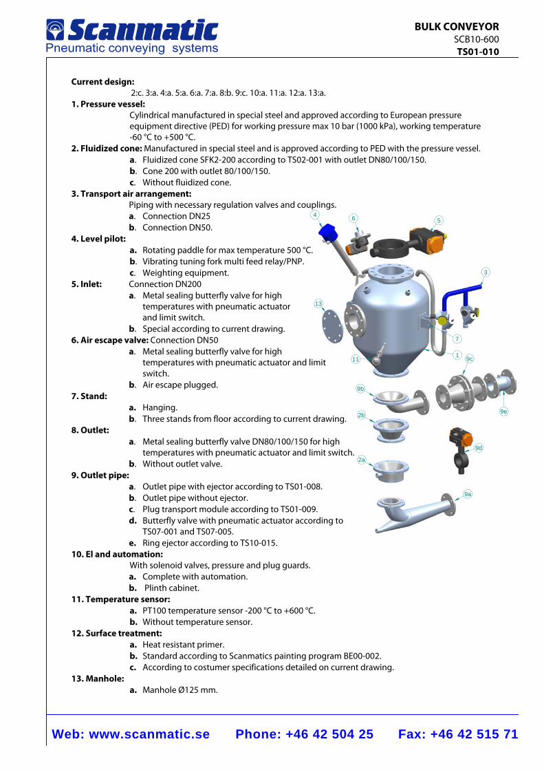
Current design: 2:c. 3:a. 4:a. 5:a. 6:a. 7:a. 8:b. 9:c. 10:a. 11:a. 12:a. 13:a.
1. Pressure vessel: Cylindrical manufactured in special steel and approved according to European pressure equipment directive (PED) for working pressure max 10 bar (1000 kPa), working temperature -60 °C to +500 °C.
2. Fluidized cone: Manufactured in special steel and is approved according to PED with the pressure vessel. a. Fluidized cone SFK2-200 according to TS02-001 with outlet DN80/100/150. b. Cone 200 with outlet 80/100/150. c. Without fluidized cone.
3. Transport air arrangement: Piping with necessary regulation valves and couplings. a. Connection DN25 b. Connection DN50.
4. Level pilot: a. Rotating paddle for max temperature 500 °C. b. Vibrating tuning fork multi feed relay/PNP. c. Weighting equipment.
5. Inlet: Connection DN200 a. Metal sealing butterfly valve for high temperatures with pneumatic actuator and limit switch. b. Special according to current drawing.
6. Air escape valve: Connection DN50 a. Metal sealing butterfly valve for high temperatures with pneumatic actuator and limit switch. b. Air escape plugged.
7. Stand: a. Hanging. b. Three stands from floor according to current drawing.
8. Outlet: a. Metal sealing butterfly valve DN80/100/150 for high
temperatures with pneumatic actuator and limit switch. b. Without outlet valve.
9. Outlet pipe: a. Outlet pipe with ejector according to TS01-008. b. Outlet pipe without ejector. c. Plug transport module according to TS01-009. d. Butterfly valve with pneumatic actuator according to TS07-001 and TS07-005. e. Ring ejector according to TS10-015.
10. El and automation: With solenoid valves, pressure and plug guards.
a. Complete with automation. b. Plinth cabinet.
11. Temperature sensor: a. PT100 temperature sensor -200 °C to +600 °C. b. Without temperature sensor.
12. Surface treatment: a. Heat resistant primer. b. Standard according to Scanmatics painting program BE00-002. c. According to costumer specifications detailed on current drawing.
13. Manhole: a. Manhole Ø125 mm.
Web: www.scanmatic.se Phone: +46 42 504 25 Fax: +46 42 515 71
AUTOMATION CABINET PLC & O.P. TS01-007
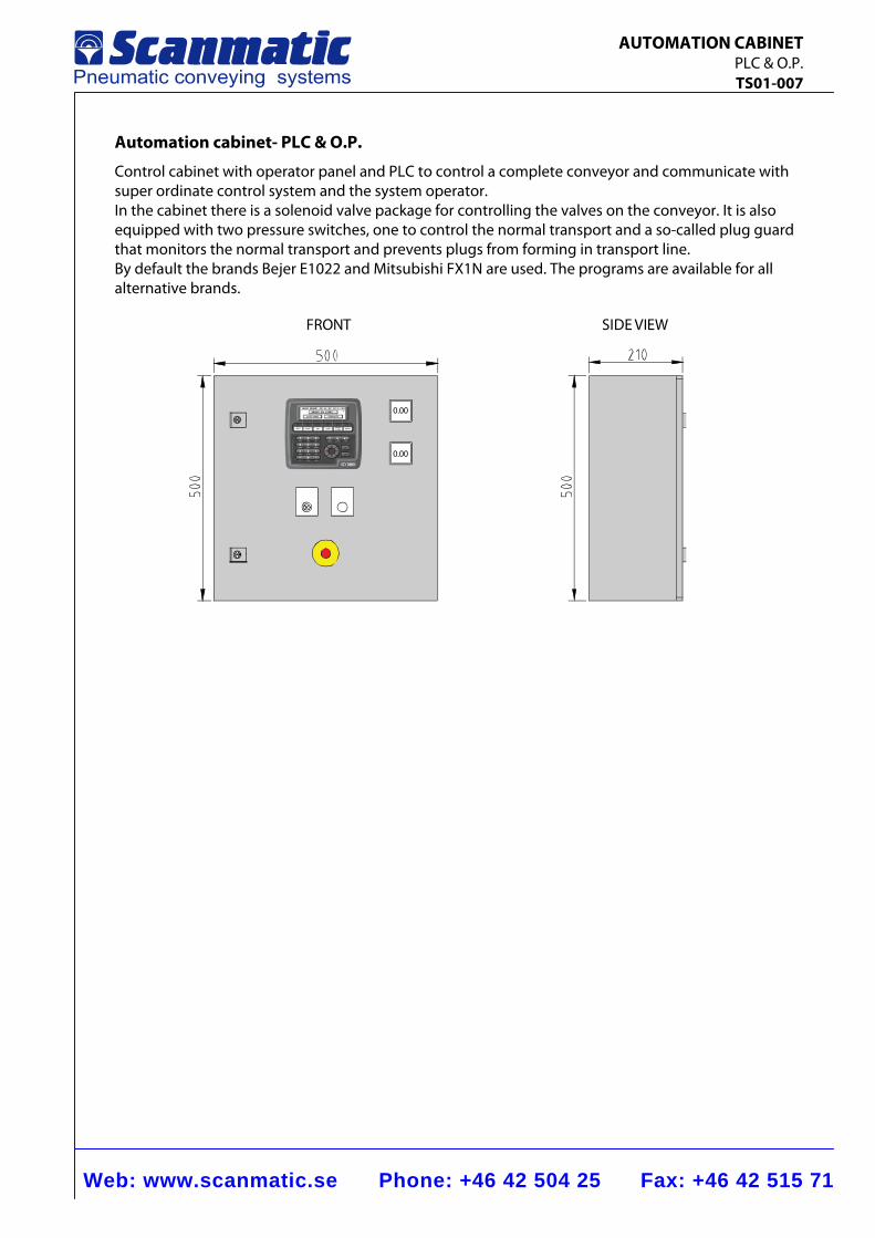
Automation cabinet- PLC & O.P.
Control cabinet with operator panel and PLC to control a complete conveyor and communicate with super ordinate control system and the system operator. In the cabinet there is a solenoid valve package for controlling the valves on the conveyor. It is also equipped with two pressure switches, one to control the normal transport and a so-called plug guard that monitors the normal transport and prevents plugs from forming in transport line. By default the brands Bejer E1022 and Mitsubishi FX1N are used. The programs are available for all alternative brands.
0.00
0.00
SIDE VIEWFRONT
Web: www.scanmatic.se Phone: +46 42 504 25 Fax: +46 42 515 71
AUTOMATION BOX TS01-014
2011
-12-
15
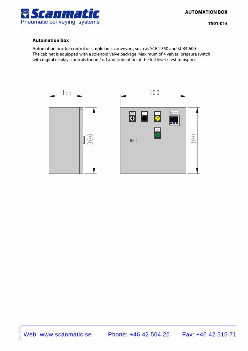
Automation box
Automation box for control of simple bulk conveyors, such as SCB4-350 and SCB4-600. The cabinet is equipped with a solenoid valve package. Maximum of 4 valves, pressure switch with digital display, controls for on / off and simulation of the full level / test transport.
Man överspänning
0-1<- Start
Simule rignivå
Transpo rtpågår
Tryckvakt
Sända reOK
Web: www.scanmatic.se Phone: +46 42 504 25 Fax: +46 42 515 71
TERMINAL CABINET Bulk conveyor TS01-012
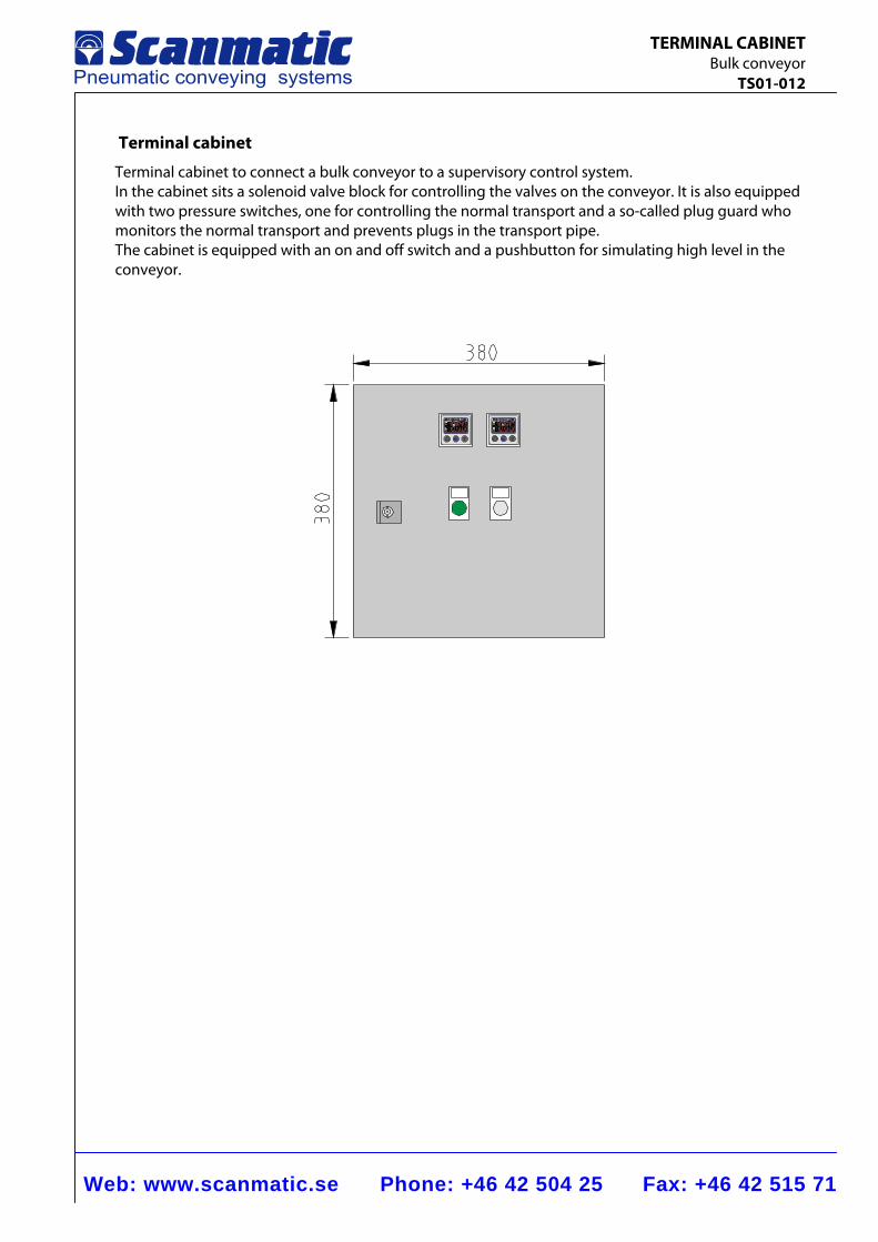
Terminal cabinet
Terminal cabinet to connect a bulk conveyor to a supervisory control system. In the cabinet sits a solenoid valve block for controlling the valves on the conveyor. It is also equipped with two pressure switches, one for controlling the normal transport and a so-called plug guard who monitors the normal transport and prevents plugs in the transport pipe. The cabinet is equipped with an on and off switch and a pushbutton for simulating high level in the conveyor.
Web: www.scanmatic.se Phone: +46 42 504 25 Fax: +46 42 515 71
OUTLET PIPE TS01-008
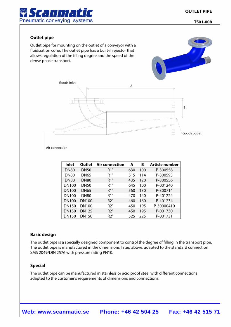
Outlet pipe
Outlet pipe for mounting on the outlet of a conveyor with a fluidization cone. The outlet pipe has a built-in ejector that allows regulation of the filling degree and the speed of the dense phase transport.
Inlet Outlet Air connection A B Article number DN80 DN50 R1" 630 100 P-300558 DN80 DN65 R1" 515 114 P-300593 DN80 DN80 R1" 435 120 P-300556
DN100 DN50 R1" 645 100 P-001240 DN100 DN65 R1" 560 130 P-300714 DN100 DN80 R1" 470 140 P-401224 DN100 DN100 R2" 460 160 P-401234 DN150 DN100 R2" 450 195 P-30000410 DN150 DN125 R2" 450 195 P-001730 DN150 DN150 R2" 525 225 P-001731
Basic design
The outlet pipe is a specially designed component to control the degree of filling in the transport pipe. The outlet pipe is manufactured in the dimensions listed above, adapted to the standard connection SMS 2049/DIN 2576 with pressure rating PN10.
Special
The outlet pipe can be manufactured in stainless or acid proof steel with different connections adapted to the customer's requirements of dimensions and connections.
B
AGoods inlet
Air connection
Goods outlet
Web: www.scanmatic.se Phone: +46 42 504 25 Fax: +46 42 515 71
PLUGTRANSPORT MODULE TS01-009
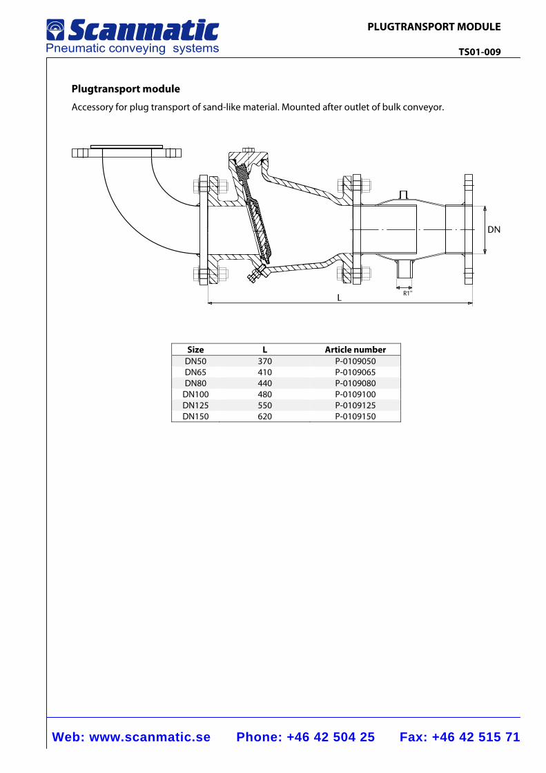
Plugtransport module
Accessory for plug transport of sand-like material. Mounted after outlet of bulk conveyor.
L
DN
R1"
Size L Article number DN50 370 P-0109050DN65 410 P-0109065DN80 440 P-0109080
DN100 480 P-0109100DN125 550 P-0109125DN150 620 P-0109150
Web: www.scanmatic.se Phone: +46 42 504 25 Fax: +46 42 515 71
PLUGTRANSPORT MODULE TS01-009
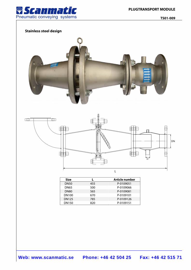
Stainless steel design
DN
R1"
L
Size L Article number DN50 455 P-0109051DN65 500 P-0109066DN80 565 P-0109081
DN100 670 P-0109101DN125 785 P-0109126DN150 820 P-0109151
Web: www.scanmatic.se Phone: +46 42 504 25 Fax: +46 42 515 71
WEIGHING EQUIPMENT Bulk conveyor TS01-013
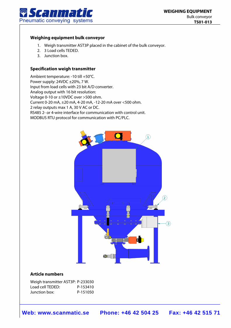
Weighing equipment bulk conveyor
1. Weigh transmitter AST3P placed in the cabinet of the bulk conveyor. 2. 3 Load cells TEDED. 3. Junction box.
Specification weigh transmitter
Ambient temperature: -10 till +50°C. Power supply: 24VDC ±20%, 7 W. Input from load cells with 23 bit A/D converter. Analog output with 16 bit resolution: Voltage 0-10 or ±10VDC over >500 ohm. Current 0-20 mA, ±20 mA, 4-20 mA, -12-20 mA over <500 ohm. 2 relay outputs max 1 A, 30 V AC or DC. RS485 2- or 4-wire interface for communication with control unit. MODBUS RTU protocol for communication with PC/PLC.
2
3
1
Article numbers
Weigh transmitter AST3P: P-233030 Load cell TEDED: P-153410 Junction box: P-151050
FLUIDIZATION CONE
Web: www.scanmatic.se Phone: +46 42 504 25 Fax: +46 42 515 71
FLUIDIZATION CONE SFK2-200 TS02-001
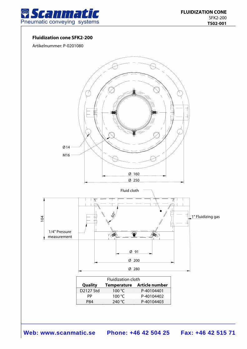
Fluidization cone SFK2-200
Artikelnummer: P-0201080
Fluidization cloth Quality Temperature Article number
D2127 Std 100 °C P-40104401 PP 100 °C P-40104402
P84 240 °C P-40104403
91Ø
200Ø
280Ø
014
Ø 160
Ø 250
Ø 14
M16
60°
1/4" Pressure measurement
1" Fluidizing gas
Fluid cloth
Web: www.scanmatic.se Phone: +46 42 504 25 Fax: +46 42 515 71
FLUIDIZATION CONE SFK2-200 TS02-001
Function
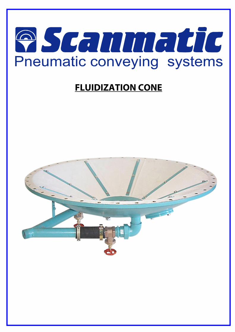
The fluidized cone is a pneumatic silo emptying arrangement which ensures complete discharge of material from different types of containers. Fluidizing of the bulk goods takes place by means of a cushion consisting of hard-wearing artificial fiber cloth. Compressed air is supplied to the cushion through a feed pipe and is evenly distributed over the whole surface of the cushion. After passing through the cushion the high quality and finely atomized air forces its way up through the bulk material, thereby effectively fluidizing it. Adhesion between the particles is eliminated and the flow characteristics are greatly improved.
Construction
The fluidized cone consists of a conical double bottom made of welded steel plate. It is provided with an upper flange for connection to a counter-flange at the outlet of the silo, and a lower flange with standard connecting dimensions. The inner bottom consists of a perforated plate on the upper side of which the artificial fiber cloth is fitted. Air supply takes place by connection to a threaded steel pipe.
Working pressure
Max. 400 kPa
Temperature
Max. 130°C with standard fluidizing cloth. Max. 200°C with special fluidizing cloth.
Range of use
As a guide for determining the relationship between the silo diameter and size of the fluidized cone, a suitable silo diameter for this type is Ø 0.2-1.0 m.
Accessories
Air control valve kit consisting of a stroke limited angle seat valve. Pressure regulator for setting the pressure and an outlet valve to control the flow of material.
Web: www.scanmatic.se Phone: +46 42 504 25 Fax: +46 42 515 71
FLUIDIZATION CONE SFK2-600 TS02-002
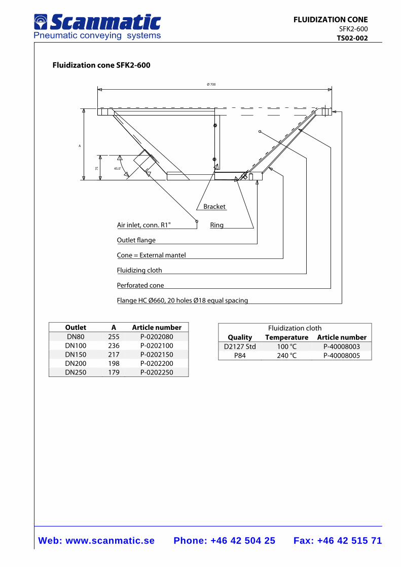
Fluidization cone SFK2-600
Ring
Bracket
Air inlet, conn. R1"
Outlet flange
Cone = External mantel
Fluidizing cloth
Perforated cone
Flange HC Ø660, 20 holes Ø18 equal spacing
45.0˚75
A
Ø 700
Outlet A Article number DN80 255 P-0202080
DN100 236 P-0202100 DN150 217 P-0202150 DN200 198 P-0202200 DN250 179 P-0202250
Fluidization cloth Quality Temperature Article number
D2127 Std 100 °C P-40008003 P84 240 °C P-40008005
Web: www.scanmatic.se Phone: +46 42 504 25 Fax: +46 42 515 71
FLUIDIZATION CONE SFK2-600 TS02-002
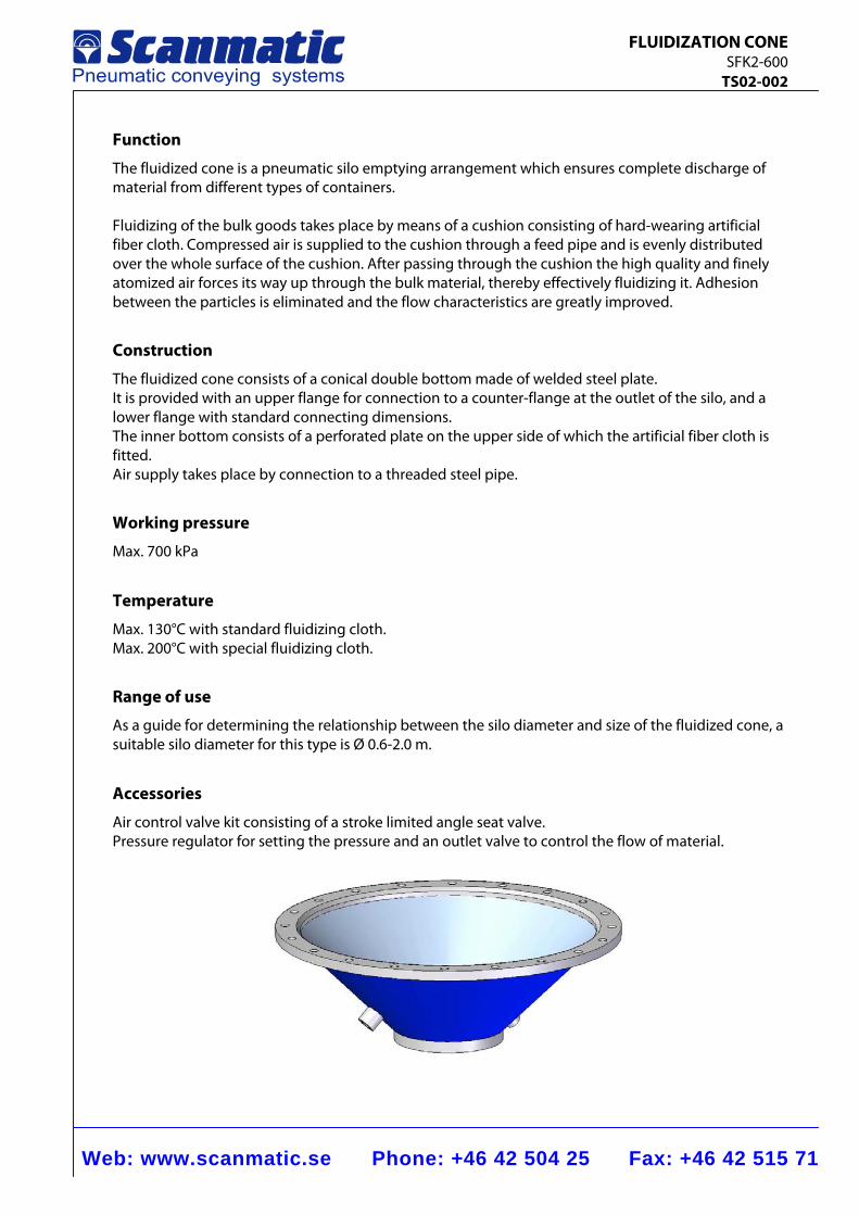
Function
The fluidized cone is a pneumatic silo emptying arrangement which ensures complete discharge of material from different types of containers. Fluidizing of the bulk goods takes place by means of a cushion consisting of hard-wearing artificial fiber cloth. Compressed air is supplied to the cushion through a feed pipe and is evenly distributed over the whole surface of the cushion. After passing through the cushion the high quality and finely atomized air forces its way up through the bulk material, thereby effectively fluidizing it. Adhesion between the particles is eliminated and the flow characteristics are greatly improved.
Construction
The fluidized cone consists of a conical double bottom made of welded steel plate. It is provided with an upper flange for connection to a counter-flange at the outlet of the silo, and a lower flange with standard connecting dimensions. The inner bottom consists of a perforated plate on the upper side of which the artificial fiber cloth is fitted. Air supply takes place by connection to a threaded steel pipe.
Working pressure
Max. 700 kPa
Temperature
Max. 130°C with standard fluidizing cloth. Max. 200°C with special fluidizing cloth.
Range of use
As a guide for determining the relationship between the silo diameter and size of the fluidized cone, a suitable silo diameter for this type is Ø 0.6-2.0 m.
Accessories
Air control valve kit consisting of a stroke limited angle seat valve. Pressure regulator for setting the pressure and an outlet valve to control the flow of material.
Web: www.scanmatic.se Phone: +46 42 504 25 Fax: +46 42 515 71
FLUIDIZED CONE SFK2-800 TS02-003
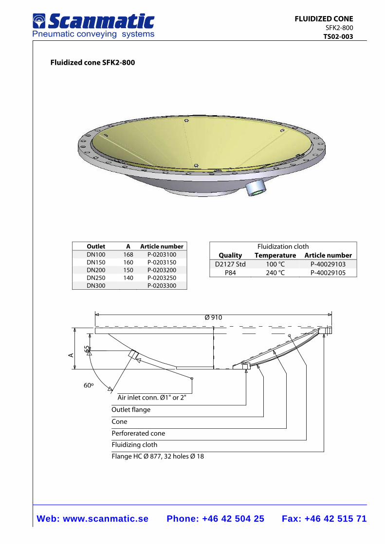
Fluidized cone SFK2-800
Outlet A Article numberDN100 168 P-0203100DN150 160 P-0203150DN200 150 P-0203200DN250 140 P-0203250DN300 P-0203300
Fluidization cloth Quality Temperature Article number
D2127 Std 100 °C P-40029103 P84 240 °C P-40029105
Ø 910
A 65
60º
Air inlet conn. Ø1" or 2"
Outlet flange
Cone
Perforerated cone
Fluidizing cloth
Flange HC Ø 877, 32 holes Ø 18
Web: www.scanmatic.se Phone: +46 42 504 25 Fax: +46 42 515 71
FLUIDIZED CONE SFK2-800 TS02-003
Function
The fluidized cone ensures that the bulk goods remain running and easy to handle by adding a sufficient amount of air to the material. Fluidizing of the bulk goods takes place by means of a cushion consisting of hard-wearing artificial fiber cloth. Compressed air is supplied to the cushion through a feed pipe and is evenly distributed over the whole surface of the cushion. After passing through the cushion the high quality and finely atomized air forces its way up through the bulk material, thereby effectively fluidizing it. Adhesion between the particles is eliminated and the flow characteristics are greatly improved.
Construction
The fluidized cone consists of a conical double bottom made of welded steel plate. It is provided with an upper flange for connection to a counter flange at the outlet of the silo, and a lower flange with standard connecting dimensions. The inner bottom consists of a perforated plate on the upper side of which the artificial fiber cloth is fitted. Air supply takes place by connection to a threaded steel pipe.
Working pressure
Max. 300 kPa
Temperature
Max. 130°C with standard fluidizing cloth. Max. 200°C with special fluidizing cloth. Range of use As a guide for determining the relationship between the silo diameter and size of the fluidized cone, a suitable silo diameter for this type of cone is 0.8–3.0 m. Accessories Air control valve kit consisting of a stroke limited angle seat valve. Pressure regulator for setting the pressure and an outlet valve to control the flow of material.
Web: www.scanmatic.se Phone: +46 42 504 25 Fax: +46 42 515 71
FLUIDIZATION CONE SFK2-1200 TS02-004
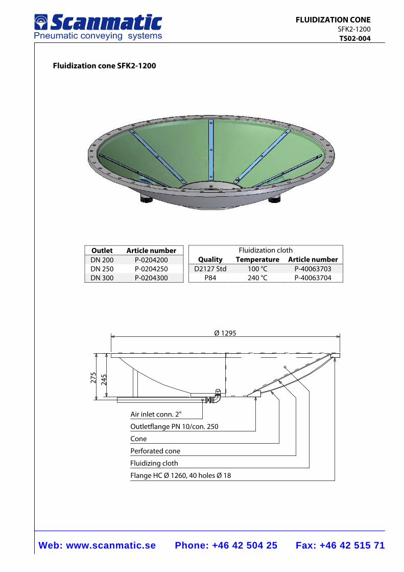
Fluidization cone SFK2-1200
Outlet Article number DN 200 P-0204200 DN 250 P-0204250 DN 300 P-0204300
Fluidization cloth Quality Temperature Article number
D2127 Std 100 °C P-40063703 P84 240 °C P-40063704
Ø 1295
275
245
Air inlet conn. 2"
Outletflange PN 10/con. 250
Cone
Perforated cone
Fluidizing cloth
Flange HC Ø 1260, 40 holes Ø 18
Web: www.scanmatic.se Phone: +46 42 504 25 Fax: +46 42 515 71
FLUIDIZATION CONE SFK2-1200 TS02-004
Function
The fluidized cone ensures that the bulk goods remain running and easy to handle by adding a sufficient amount of air to the material. Fluidizing of the bulk goods takes place by means of a cushion consisting of hard-wearing artificial fiber cloth. Compressed air is supplied to the cushion through a feed pipe and is evenly distributed over the whole surface of the cushion. After passing through the cushion the high quality and finely atomized air forces its way up through the bulk material, thereby effectively fluidizing it. Adhesion between the particles is eliminated and the flow characteristics are greatly improved. Construction The fluidized cone consists of a conical double bottom made of welded steel plate. It is provided with an upper flange for connection to a counterflange at the outlet of the silo, and a lower flange with standard connecting dimensions. The inner bottom consists of a perforated plate on the upper side of which the artificial fiber cloth is fitted. Air supply takes place by connection to a threaded steel pipe.
Working pressure
Max. 300 kPa
Temperature
Max.130°C with standard fluidizing cloth. Max. 200°C with special fluidizing cloth. Range of use As a guide for determining the relationship between the silo diameter and size of the fluidized cone, a suitable silo diameter for this type is 1.2–4.0 m. Accessories Air control valve kit consisting of a stroke limited angle seat valve. Pressure regulator for setting the pressure and an outlet valve to control the flow of material.
Web: www.scanmatic.se Phone: +46 42 504 25 Fax: +46 42 515 71
FLUIDIZATION CONE SFK2-2000 TS02-005
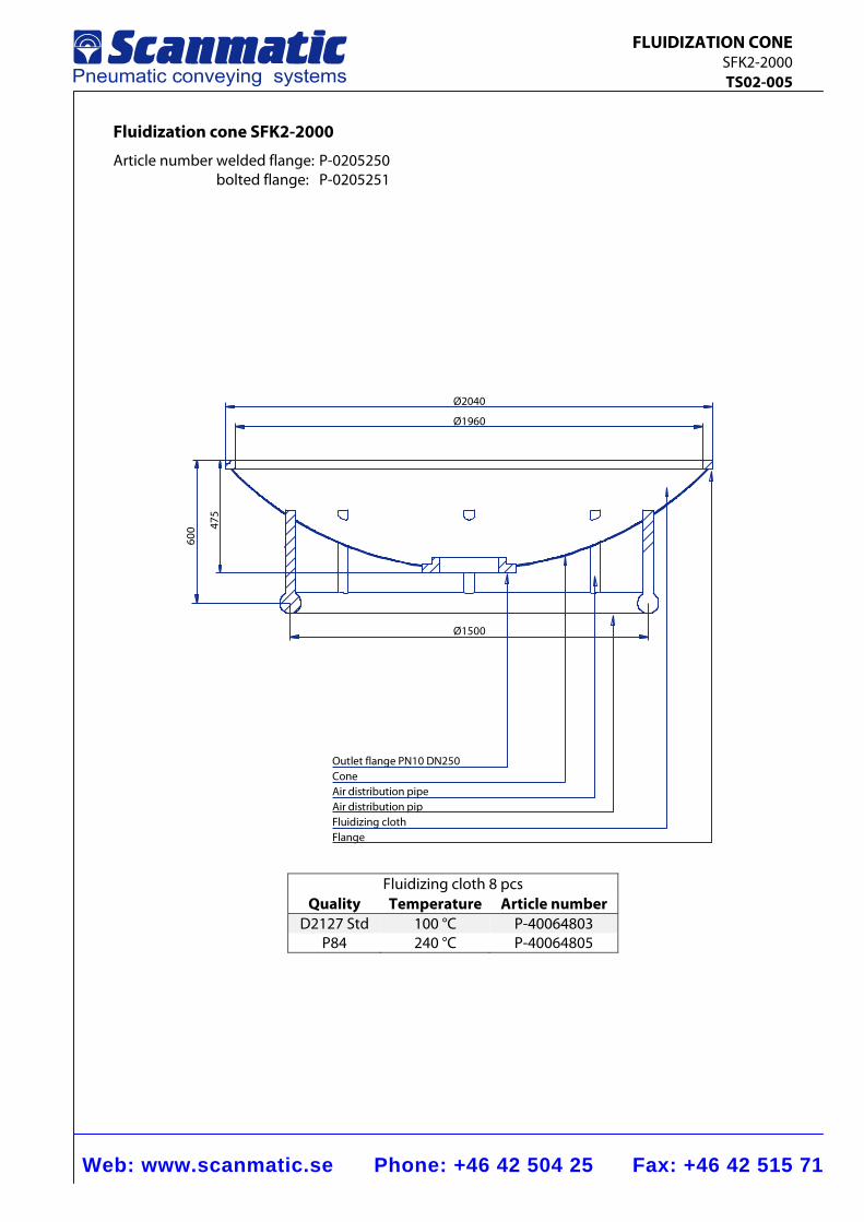
Fluidization cone SFK2-2000
Article number welded flange: P-0205250 bolted flange: P-0205251
Fluidizing cloth 8 pcs Quality Temperature Article number
D2127 Std 100 °C P-40064803 P84 240 °C P-40064805
475
600
Ø2040
Ø1960
Ø1500
Outlet flange PN10 DN250ConeAir distribution pipeAir distribution pipFluidizing clothFlange
Web: www.scanmatic.se Phone: +46 42 504 25 Fax: +46 42 515 71
FLUIDIZATION CONE SFK2-2000 TS02-005
Function
The fluidized cone ensures that the bulk goods remain running and easy to handle by adding a sufficient amount of air to the material. Fluidizing of the bulk goods takes place by means of a cushion consisting of hard-wearing artificial fiber cloth. Compressed air is supplied to the cushion through a feed pipe and is evenly distributed over the whole surface of the cushion. After passing through the cushion the high quality and finely atomized air forces its way up through the bulk material, thereby effectively fluidizing it. Adhesion between the particles is eliminated and the flow characteristics are greatly improved. Construction The fluidized cone consists of a conical double bottom made of welded steel plate. It is provided with an upper flange for connection to the outlet of the silo, and a lower flange with standard connecting dimensions. The fluidized cone is available in two versions, one that is bolted to a counter flange and one that is welded directly to the container. The inner bottom consists of a perforated plate on the upper side of which the artificial fiber cloth is fitted. Air supply takes place by connection to a threaded steel pipe.
Working pressure
Max. 300 kPa
Temperature
Max. 130°C with standard fluidizing cloth. Max. 200°C with special fluidizing cloth. Range of use As a guide for determining the relationship between the silo diameter and size of the fluidized cone, a suitable silo diameter for this type is 2.0–6.0 m. Accessories Air control valve equipment consisting of slide valve for regulating the necessary air volume and on - off valve controlled by solenoid valve.
Web: www.scanmatic.se Phone: +46 42 504 25 Fax: +46 42 515 71
FLUIDIZATION CONE SFK2-3000 TS02-007
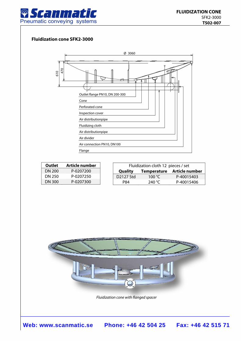
Flange
Air distributionpipe
Air divider
Air connection PN10, DN100
Inspection cover
Air distributionpipe
Fluidizing cloth
Perforated cone
Outlet flange PN10, DN 200-300
Cone
Ø 3060
470
610
Fluidization cone SFK2-3000
Outlet Article number DN 200 P-0207200 DN 250 P-0207250 DN 300 P-0207300
Fluidization cloth 12 pieces / set Quality Temperature Article number
D2127 Std 100 °C P-40015403 P84 240 °C P-40015406
Fluidization cone with flanged spacer
Web: www.scanmatic.se Phone: +46 42 504 25 Fax: +46 42 515 71
FLUIDIZATION CONE SFK2-3000 TS02-007
Function
The fluidized cone is a pneumatic silo emptying arrangement which ensures complete discharge of material from different types of containers. Fluidizing of the bulk goods takes place by means of a cushion consisting of hard-wearing artificial fiber cloth. Compressed air is supplied to the cushion through a feed pipe and is evenly distributed over the whole surface of the cushion. After passing through the cushion the high quality and finely atomized air forces its way up through the bulk material, thereby effectively fluidizing it. Adhesion between the particles is eliminated and the flow characteristics are greatly improved.
Construction
The fluidized cone consists of a conical double bottom made of welded steel plate. It is provided with an upper flange for connection to a counter flange at the outlet of the silo, and a lower flange with standard connecting dimensions. The inner bottom consists of a perforated plate on the upper side of which the artificial fiber cloth is fitted. Air supply takes place by a PN10/DN100 flange connection
Working pressure
Max. 300 kPa
Temperature
Max. 130°C with standard fluidizing cloth. Max. 200°C with special fluidizing cloth.
Range of use
As a guide for determining the relationship between the silo diameter and size of the fluidized cone, a suitable silo diameter for this type is ≤3,0m.
Accessories
Air control valve equipment consisting of electric-pneumatic valve connection DN100.
Web: www.scanmatic.se Phone: +46 42 504 25 Fax: +46 42 515 71
FLUIDIZATION CONE SFK2-2000-2 TS02-008
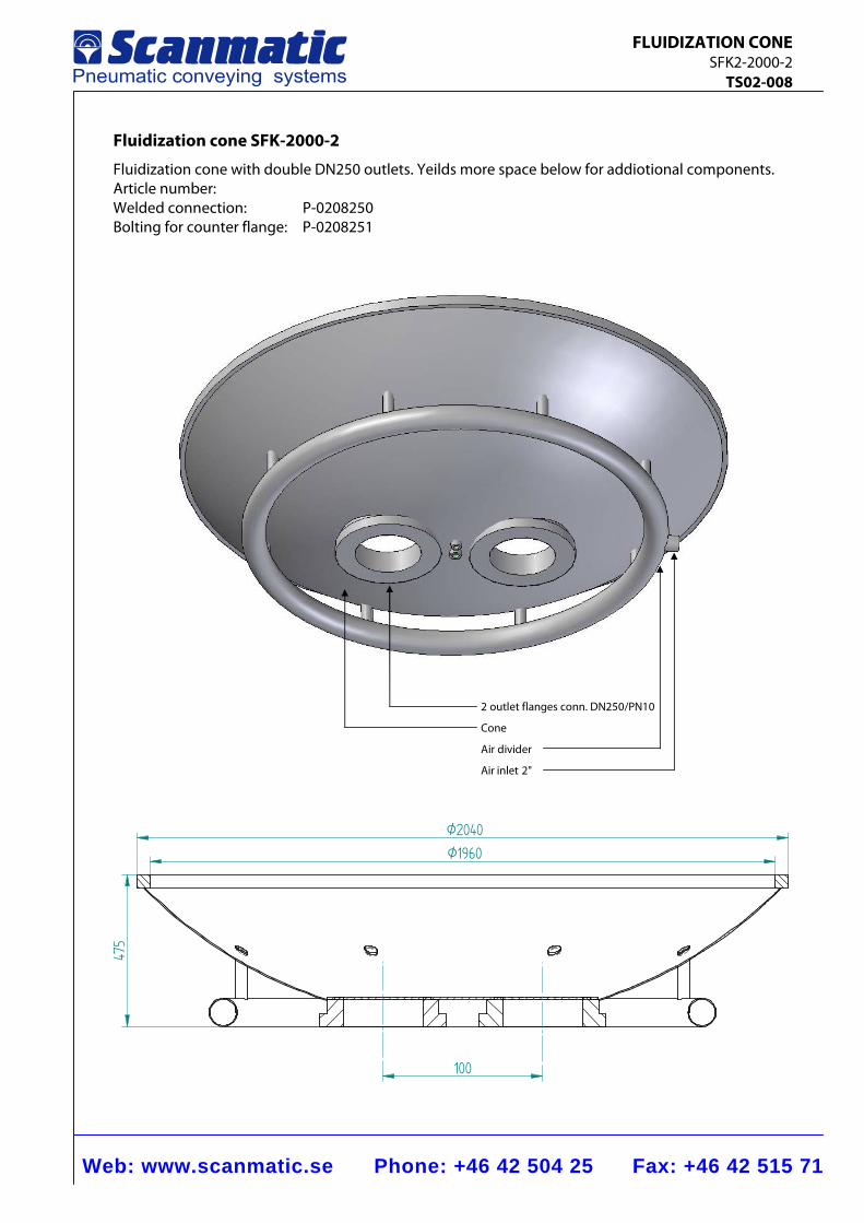
475
100
Ø2040
Ø1960
Fluidization cone SFK-2000-2
Fluidization cone with double DN250 outlets. Yeilds more space below for addiotional components. Article number: Welded connection: P-0208250 Bolting for counter flange: P-0208251
2 outlet flanges conn. DN250/PN10
Cone
Air divider
Air inlet 2"
Web: www.scanmatic.se Phone: +46 42 504 25 Fax: +46 42 515 71
FLUIDIZATION CONE SFK2-2000-2 TS02-008
Function
The fluidized cone ensures that the bulk goods remain running and easy to handle by adding a sufficient amount of air to the material. Fluidizing of the bulk goods takes place by means of a cushion consisting of hard-wearing artificial fiber cloth. Compressed air is supplied to the cushion through a feed pipe and is evenly distributed over the whole surface of the cushion. After passing through the cushion the high quality and finely atomized air forces its way up through the bulk material, thereby effectively fluidizing it. Adhesion between the particles is eliminated and the flow characteristics are greatly improved. Construction The fluidized cone consists of a conical double bottom made of welded steel plate. It is provided with an upper flange for connection to a counter flange at the outlet of the silo, and a lower flange with standard connecting dimensions. The inner bottom consists of a perforated plate on the upper side of which the artificial fiber cloth is fitted. Air supply takes place by connection to a threaded steel pipe DN50.
Working pressure
Max. 300 kPa
Temperature
Max. 130°C with standard fluidizing cloth. Max. 200°C with special fluidizing cloth. Range of use As a guide for determining the relationship between the silo diameter and size of the fluidized cone, a suitable silo diameter for this type is 2.0–6.0 m. Accessories Air control valve equipment consisting of slide valve for regulating the necessary air volume and on - off valve controlled by solenoid valve.
Web: www.scanmatic.se Phone: +46 42 504 25 Fax: +46 42 515 71
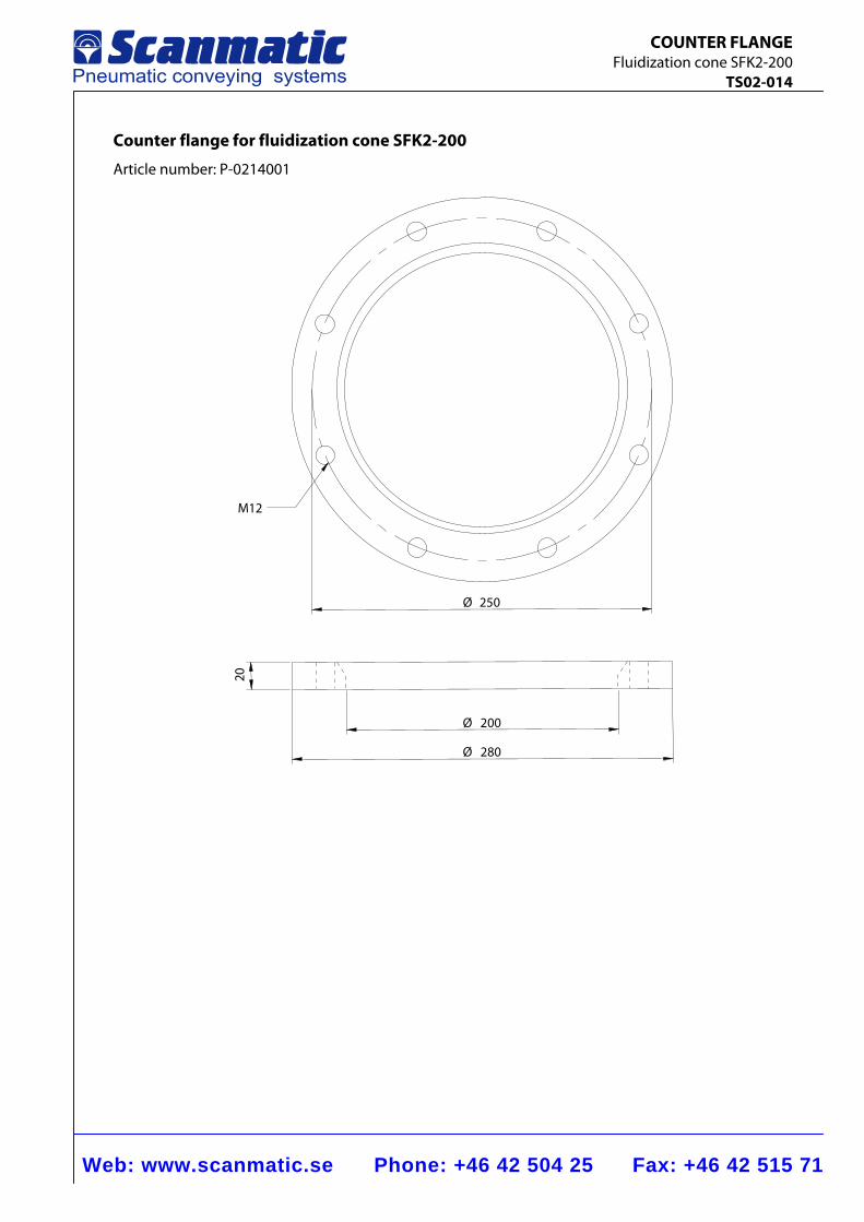
COUNTER FLANGE Fluidization cone SFK2-200 TS02-014
Counter flange for fluidization cone SFK2-200
Article number: P-0214001
200Ø
280Ø
Ø 250
M12
20
Web: www.scanmatic.se Phone: +46 42 504 25 Fax: +46 42 515 71
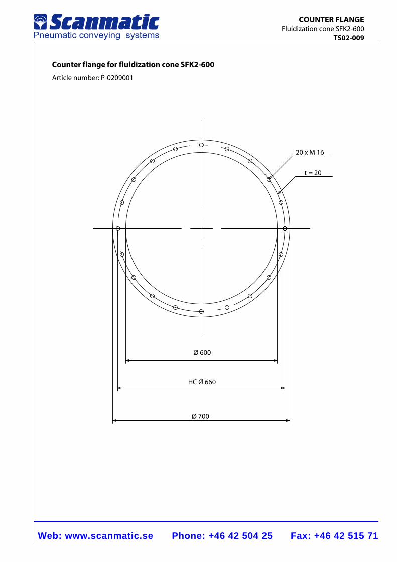
COUNTER FLANGE Fluidization cone SFK2-600 TS02-009
Counter flange for fluidization cone SFK2-600
Article number: P-0209001
Ø 600
HC Ø 660
Ø 700
20 x M 16
t = 20
Web: www.scanmatic.se Phone: +46 42 504 25 Fax: +46 42 515 71
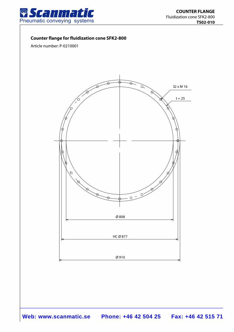
COUNTER FLANGE Fluidization cone SFK2-800 TS02-010
Counter flange for fluidization cone SFK2-800
Article number: P-0210001
32 x M 16
t = 25
Ø 808
HC Ø 877
Ø 910
Web: www.scanmatic.se Phone: +46 42 504 25 Fax: +46 42 515 71
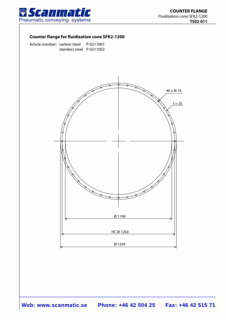
COUNTER FLANGE Fluidization cone SFK2-1200 TS02-011
Counter flange for fluidization cone SFK2-1200
Article number: carbon steel P-0211001 stainless steel P-0211002
40 x M 16
t = 25
Ø 1190
HC Ø 1260
Ø 1295
Web: www.scanmatic.se Phone: +46 42 504 25 Fax: +46 42 515 71
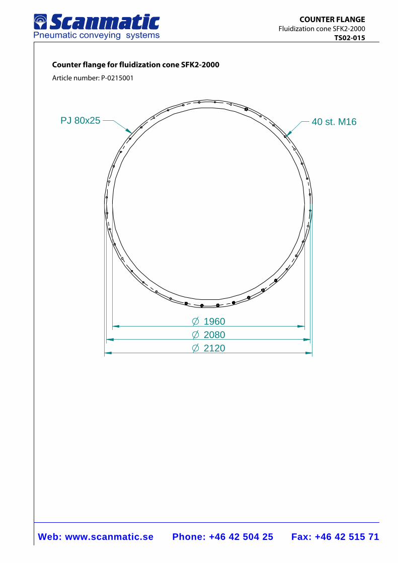
COUNTER FLANGE Fluidization cone SFK2-2000 TS02-015
Counter flange for fluidization cone SFK2-2000
Article number: P-0215001
O 1960
O 2120O 2080
PJ 80x25 40 st. M16
Web: www.scanmatic.se Phone: +46 42 504 25 Fax: +46 42 515 71
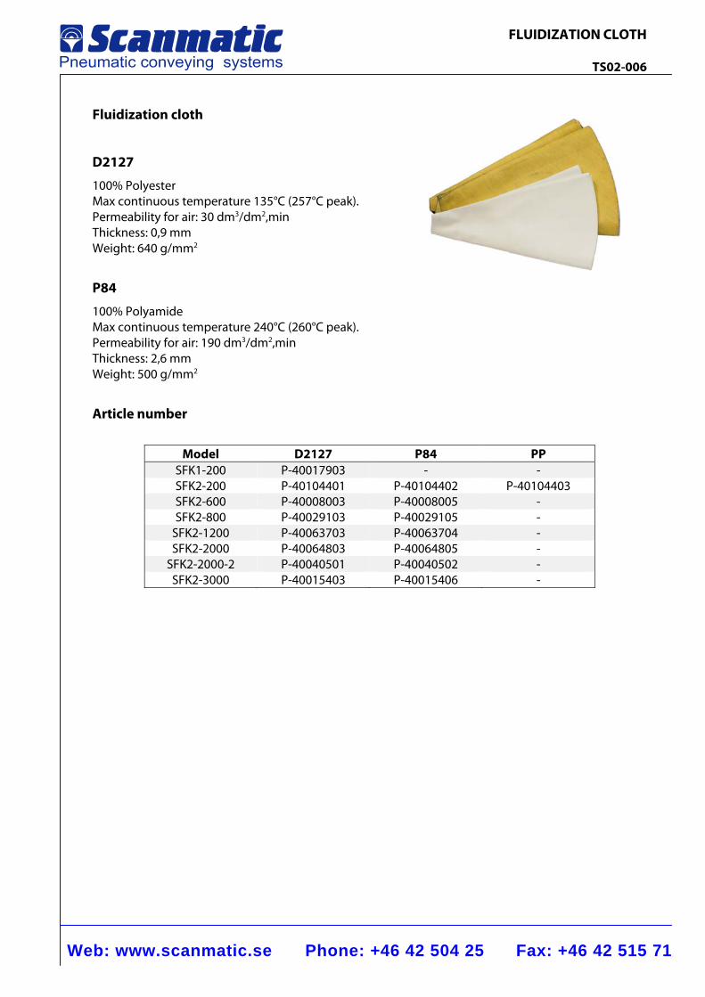
FLUIDIZATION CLOTH TS02-006
Fluidization cloth
D2127
100% Polyester Max continuous temperature 135°C (257°C peak). Permeability for air: 30 dm3/dm2,min Thickness: 0,9 mm Weight: 640 g/mm2
P84
100% Polyamide Max continuous temperature 240°C (260°C peak). Permeability for air: 190 dm3/dm2,min Thickness: 2,6 mm Weight: 500 g/mm2
Article number
Model D2127 P84 PP
SFK1-200 P-40017903 - - SFK2-200 P-40104401 P-40104402 P-40104403 SFK2-600 P-40008003 P-40008005 - SFK2-800 P-40029103 P-40029105 -
SFK2-1200 P-40063703 P-40063704 - SFK2-2000 P-40064803 P-40064805 -
SFK2-2000-2 P-40040501 P-40040502 - SFK2-3000 P-40015403 P-40015406 -
Web: www.scanmatic.se Phone: +46 42 504 25 Fax: +46 42 515 71
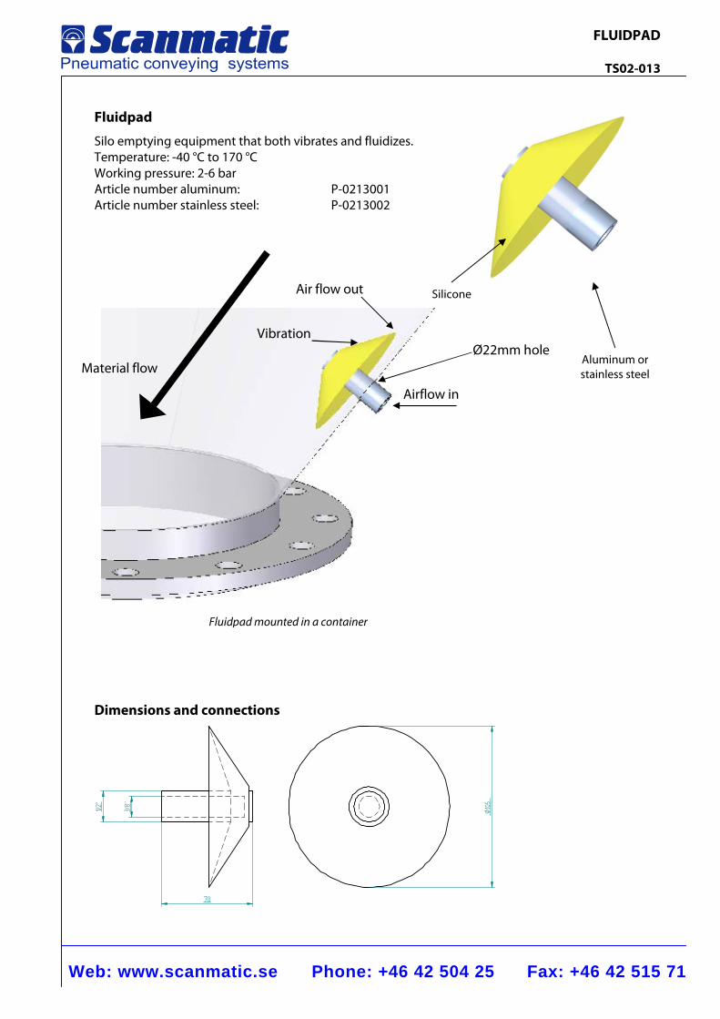
FLUIDPAD TS02-013
Material flow
Air flow out
VibrationØ22mm hole
Airflow in
Fluidpad
Silo emptying equipment that both vibrates and fluidizes. Temperature: -40 °C to 170 °C Working pressure: 2-6 bar Article number aluminum: P-0213001 Article number stainless steel: P-0213002
Dimensions and connections
Ø105
1/2”
3/8”
70
Fluidpad mounted in a container
Silicone
Aluminum orstainless steel
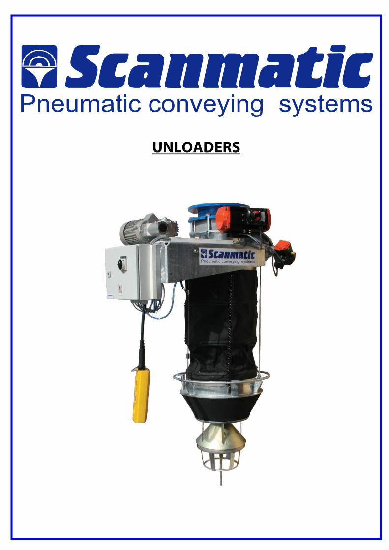
UNLOADERS
Web: www.scanmatic.se Phone: +46 42 504 25 Fax: +46 42 515 71
UNLOADER SUB2 TS03-001
Ø 520Ø 360
Air escapeDN100 PN10
InletDN250 PN10
Diffuser cone
Connection cone
575
B
A
C
280
100
Supportingcables
Cones
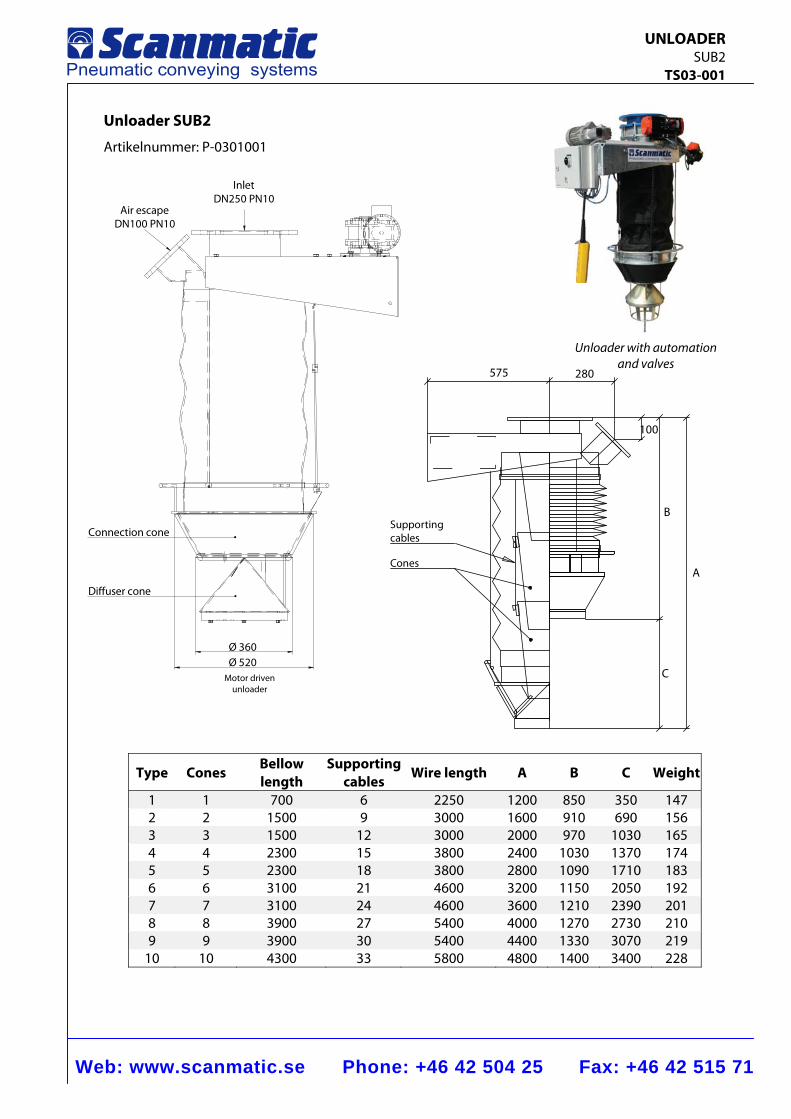
Unloader SUB2
Artikelnummer: P-0301001
Type Cones Bellow length
Supporting cables Wire length A B C Weight
1 1 700 6 2250 1200 850 350 147 2 2 1500 9 3000 1600 910 690 156 3 3 1500 12 3000 2000 970 1030 165 4 4 2300 15 3800 2400 1030 1370 174 5 5 2300 18 3800 2800 1090 1710 183 6 6 3100 21 4600 3200 1150 2050 192 7 7 3100 24 4600 3600 1210 2390 201 8 8 3900 27 5400 4000 1270 2730 210 9 9 3900 30 5400 4400 1330 3070 219
10 10 4300 33 5800 4800 1400 3400 228
Motor driven unloader
Unloader with automation and valves
Web: www.scanmatic.se Phone: +46 42 504 25 Fax: +46 42 515 71
UNLOADER SUB2 TS03-001
Function The unloader is erected below an outlet unit from e.g. a silo in order to enable a flexible and dust free loading of bulk vehicles and other containers. It is workable within a varying range of loading heights and is provided with three point suspensions in steel wires and a winch device. The unloader is driven by an electrical worm gear motor or manually by a hand wheel. Basic design
Inlet flange connection NW250/PN10 Venting flange connection NW100/PN10 Bellow made of heavy PVC-coated fabric with sown in steel rings. Steel parts are surface protected with zinc. Outlet connection in the shape of a rubber coated cone for self–sealing in openings with Ø 380 –480 mm. Stainless wires for suspension of winches and cones. Drive: Electric motor: 0.55 kW, 230/400 V, 50 Hz, IP 54, 314
Alternative hand operated Adjustable limit switches for both end positions. Limit switch stops winch motor automatically when the outlet cone reaches the point of connection. Control box with all electric connections on a connection–plinth. Working temperature range:-20° - +80°C Additional equipment
Inlet valve: Butterfly alt. slide, connection 250/PN10, el-pneumatically alt. manually (lever alt. wheel) controlled incl. of necessary intermediate part for erection. Installation dimension: 135 mm.
Air escape valve: Butterfly, connection 100/PN10, el-pneumatically or manually (lever) controlled.
Level indicator: 1. Air pressure monitoring 2. Vibration indicator TS09-005. 3. Capacitive indicator TS09-007.
4. Rotating paddle indicator TS09-006.
Maneuvering: 1. Automation according to TS03-002 2. Automation according to TS03-003. 3. Manual winch according to TS03-005
Dust cap: Mounted on the connection cone to minimize dusting when unloading open vehicles TS03-004.
Special equipment:
The unloader can be completed by several details e.g. − complete control equipment for different types of additional equipment − control buttons in separate equipment − included parts in stainless alternatively acid proof steel
Web: www.scanmatic.se Phone: +46 42 504 25 Fax: +46 42 515 71
MANEUVER EQUIPMENT For SUB2 2 buttons TS03-002
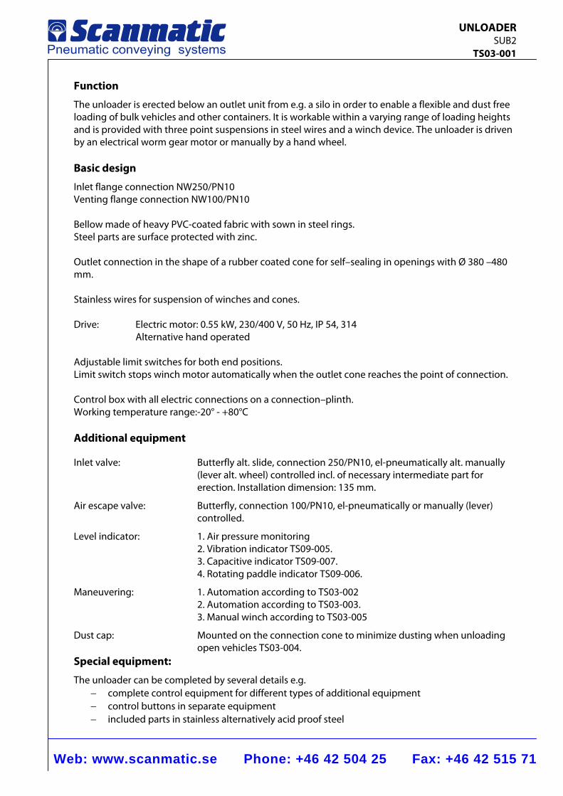
Maneuver equipment for SUB2 with 2 buttons
Maneuver equipment for operation of the unloader, available in two alternatives
Alternative: 1 Maneuver buttons in the front of a cabinet
UP
DOWN
EMERGENCY STOP
380
300
155
Alternative 2: Maneuver buttons in separately hanging box
UP
DOWN
EMERGENCY STOP
Web: www.scanmatic.se Phone: +46 42 504 25 Fax: +46 42 515 71
MANEUVER EQUIPMENT For SUB2 4 buttons TS03-003
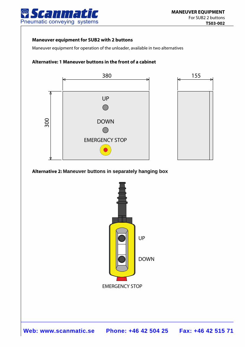
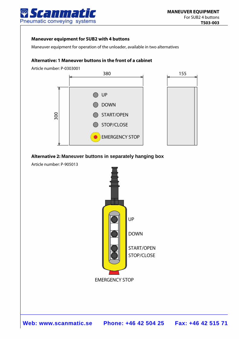
Maneuver equipment for SUB2 with 4 buttons
Maneuver equipment for operation of the unloader, available in two alternatives
Alternative: 1 Maneuver buttons in the front of a cabinet
Article number: P-0303001
UP
380
300
155
DOWN
START/OPEN
STOP/CLOSE
EMERGENCY STOP
Alternative 2: Maneuver buttons in separately hanging box
Article number: P-905013
UP
DOWN
START/OPENSTOP/CLOSE
EMERGENCY STOP
BAG EMPTIERS
Web: www.scanmatic.se Phone: +46 42 504 25 Fax: +46 42 515 71
ONE-BAG SLITTER SSM2-1 TS04-001
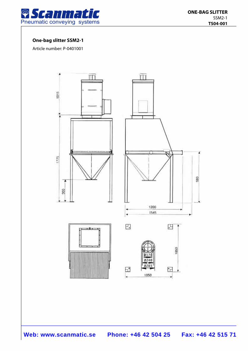
One-bag slitter SSM2-1
Article number: P-0401001
Web: www.scanmatic.se Phone: +46 42 504 25 Fax: +46 42 515 71
ONE-BAG SLITTER SSM2-1 TS04-001
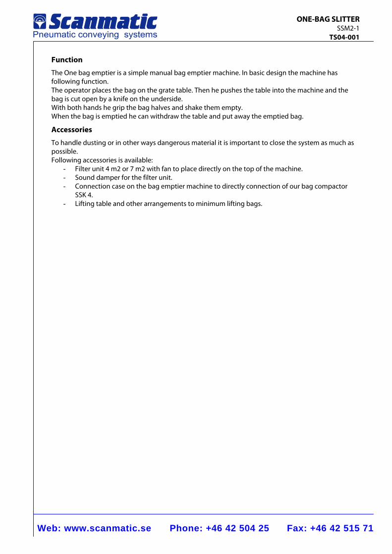
Function
The One bag emptier is a simple manual bag emptier machine. In basic design the machine has following function. The operator places the bag on the grate table. Then he pushes the table into the machine and the bag is cut open by a knife on the underside. With both hands he grip the bag halves and shake them empty. When the bag is emptied he can withdraw the table and put away the emptied bag.
Accessories
To handle dusting or in other ways dangerous material it is important to close the system as much as possible. Following accessories is available:
- Filter unit 4 m2 or 7 m2 with fan to place directly on the top of the machine. - Sound damper for the filter unit. - Connection case on the bag emptier machine to directly connection of our bag compactor
SSK 4. - Lifting table and other arrangements to minimum lifting bags.
Web: www.scanmatic.se Phone: +46 42 504 25 Fax: +46 42 515 71
BAG SLITTER SSM3-100 TS04-002
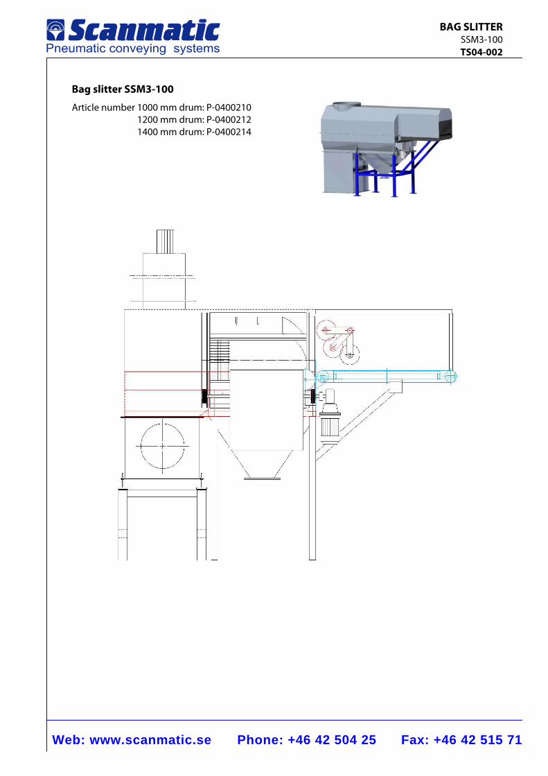
Bag slitter SSM3-100
Article number 1000 mm drum: P-0400210 1200 mm drum: P-0400212 1400 mm drum: P-0400214
Web: www.scanmatic.se Phone: +46 42 504 25 Fax: +46 42 515 71
BAG SLITTER SSM3-100 TS04-002
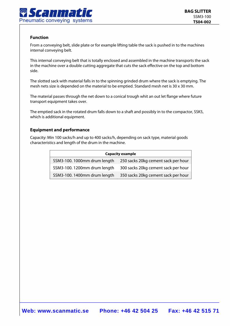
Function
From a conveying belt, slide plate or for example lifting table the sack is pushed in to the machines internal conveying belt. This internal conveying belt that is totally enclosed and assembled in the machine transports the sack in the machine over a double cutting aggregate that cuts the sack effective on the top and bottom side. The slotted sack with material falls in to the spinning grinded drum where the sack is emptying. The mesh nets size is depended on the material to be emptied. Standard mesh net is 30 x 30 mm. The material passes through the net down to a conical trough whit an out let flange where future transport equipment takes over. The emptied sack in the rotated drum falls down to a shaft and possibly in to the compactor, SSK5, which is additional equipment.
Equipment and performance
Capacity: Min 100 sacks/h and up to 400 sacks/h, depending on sack type, material goods characteristics and length of the drum in the machine.
Capacity example
SSM3-100. 1000mm drum length 250 sacks 20kg cement sack per hour
SSM3-100. 1200mm drum length 300 sacks 20kg cement sack per hour
SSM3-100. 1400mm drum length 350 sacks 20kg cement sack per hour
Web: www.scanmatic.se Phone: +46 42 504 25 Fax: +46 42 515 71
BAG SLITTER SSM3-100 TS04-002
Wastage
The goods waste is depending on type of sack and goods characteristics. The eventual wastage is following the sack down the shaft. Example: 20kg cement, 0.1-1 mm/particle in paper sack gives less than 0.2% wastage.
Surface finish
Painting program according to Scanmatic standard TS-7000 It can also be delivered in stainless steel or other customers demands.
Electrical connection
400 V, 50 Hz, IP 56, 16 A Additional components as lifting table, filter, feeding belt conveyor etc. (components that is bulky for transportation) assemblies by electrician in place.
Air connection
8mm instrumental air hose
Emptying time
Emptying time is that time the sack is placed in the drum. This time is varying depend on the material and type of sack. By delivery the machine is adjusted to maximum emptying time. To accomplish shorter emptying time one have to dismantle the pointed axel which is screwed on the inside of the drum. The feeding time has to be adjusted to the emptying time.
Additional components (see product catalogue)
− Cartridge air filter with mechanical cleaning − Compactor. SSK4 or SSK5 − Feeding belt conveyor − Lifting table − Vacuum lift − Screw conveyor
Web: www.scanmatic.se Phone: +46 42 504 25 Fax: +46 42 515 71
BIG BAG EMPTIER SSS2 TS04-003
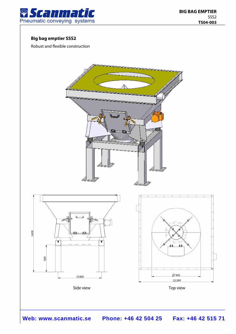
Big bag emptier SSS2
Robust and flexible construction
500
1428
800 900
1380 Side view Top view
Web: www.scanmatic.se Phone: +46 42 504 25 Fax: +46 42 515 71
BIG BAG EMPTIER SSS2 TS04-003
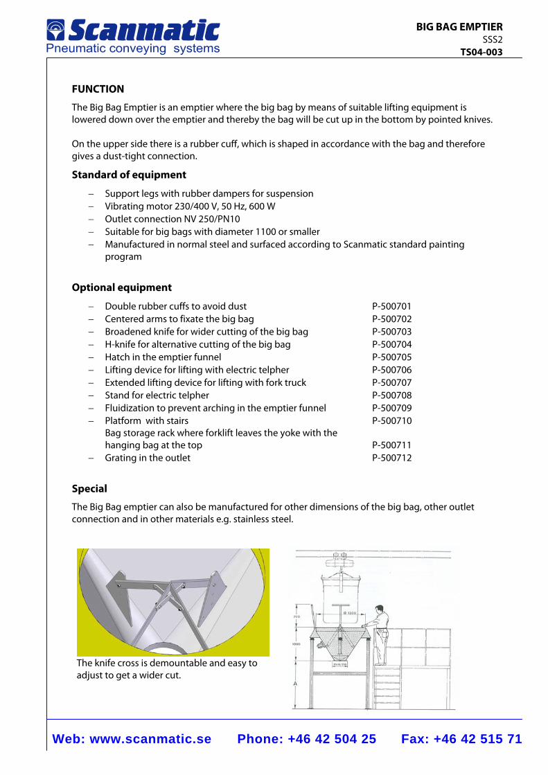
FUNCTION
The Big Bag Emptier is an emptier where the big bag by means of suitable lifting equipment is lowered down over the emptier and thereby the bag will be cut up in the bottom by pointed knives. On the upper side there is a rubber cuff, which is shaped in accordance with the bag and therefore gives a dust-tight connection.
Standard of equipment
− Support legs with rubber dampers for suspension − Vibrating motor 230/400 V, 50 Hz, 600 W − Outlet connection NV 250/PN10 − Suitable for big bags with diameter 1100 or smaller − Manufactured in normal steel and surfaced according to Scanmatic standard painting
program
Optional equipment
− Double rubber cuffs to avoid dust P-500701 − Centered arms to fixate the big bag P-500702 − Broadened knife for wider cutting of the big bag P-500703 − H-knife for alternative cutting of the big bag P-500704 − Hatch in the emptier funnel P-500705 − Lifting device for lifting with electric telpher P-500706 − Extended lifting device for lifting with fork truck P-500707 − Stand for electric telpher P-500708 − Fluidization to prevent arching in the emptier funnel P-500709 − Platform with stairs P-500710
Bag storage rack where forklift leaves the yoke with the hanging bag at the top P-500711
− Grating in the outlet P-500712
Special
The Big Bag emptier can also be manufactured for other dimensions of the big bag, other outlet connection and in other materials e.g. stainless steel.
The knife cross is demountable and easy to adjust to get a wider cut.
Web: www.scanmatic.se Phone: +46 42 504 25 Fax: +46 42 515 71
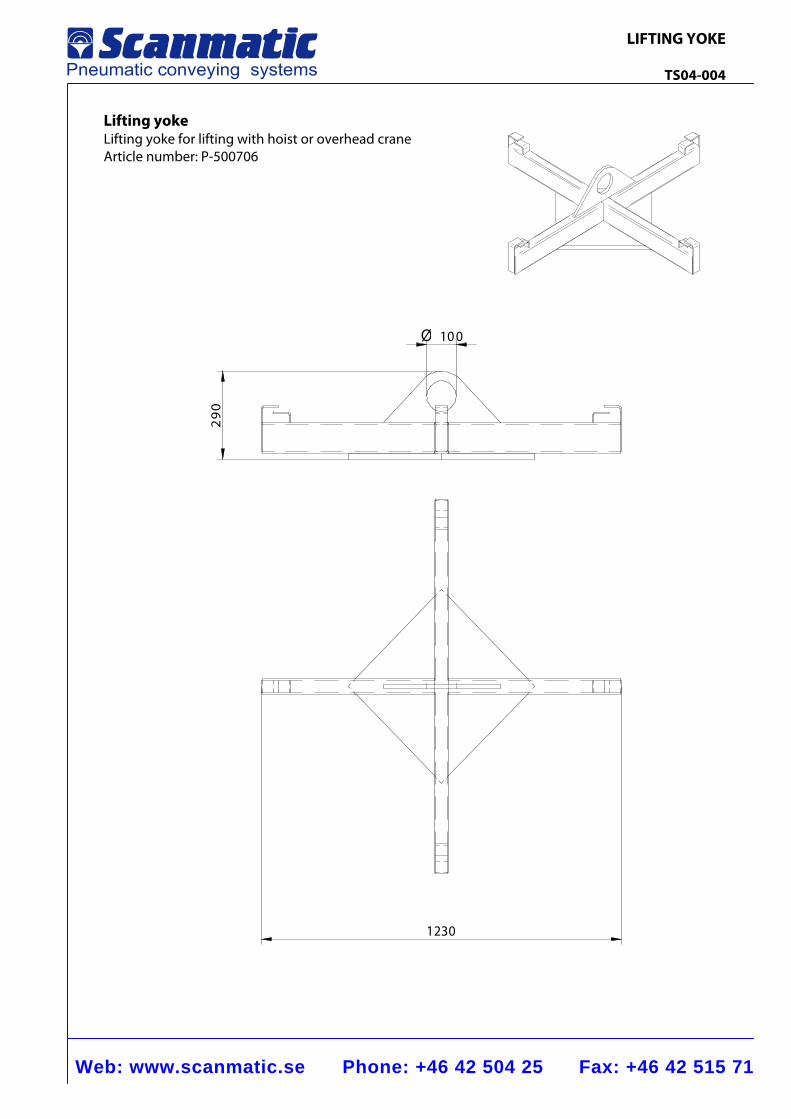
LIFTING YOKE TS04-004
Lifting yoke Lifting yoke for lifting with hoist or overhead crane Article number: P-500706
1230
10 0Ø
92
0
COMPRIMATORS
Web: www.scanmatic.se Phone: +46 42 504 25 Fax: +46 42 515 71
COMPACTOR SSK4 TS05-001
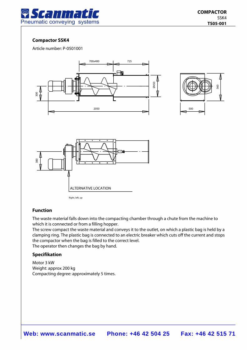
Compactor SSK4
Article number: P-0501001
Function
The waste material falls down into the compacting chamber through a chute from the machine to which it is connected or from a filling hopper. The screw compact the waste material and conveys it to the outlet, on which a plastic bag is held by a clamping ring. The plastic bag is connected to an electric breaker which cuts off the current and stops the compactor when the bag is filled to the correct level. The operator then changes the bag by hand.
Specifikation
Motor 3 kW Weight: approx 200 kg Compacting degree: approximately 5 times.
500
560
300
2050
725
Ø45
0
700x400
380
ALTERNATIVE LOCATION
Right, left, up
Web: www.scanmatic.se Phone: +46 42 504 25 Fax: +46 42 515 71
COMPACTOR SSK5 TS05-002
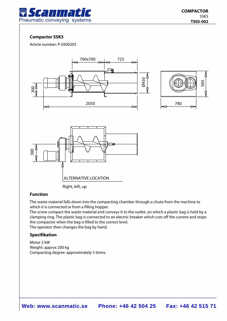
Compactor SSK5
Article number: P-0500205
780
560
300
2050
725
Ø45
0
700x700
380
ALTERNATIVE LOCATION
Right, left, up
Function
The waste material falls down into the compacting chamber through a chute from the machine to which it is connected or from a filling hopper. The screw compact the waste material and conveys it to the outlet, on which a plastic bag is held by a clamping ring. The plastic bag is connected to an electric breaker which cuts off the current and stops the compactor when the bag is filled to the correct level. The operator then changes the bag by hand.
Specifikation
Motor 3 kW Weight: approx 200 kg Compacting degree: approximately 5 times.
Filters
Web: www.scanmatic.se Phone: +46 42 504 25 Fax: +46 42 515 71
FILTER Silotop TS06-001
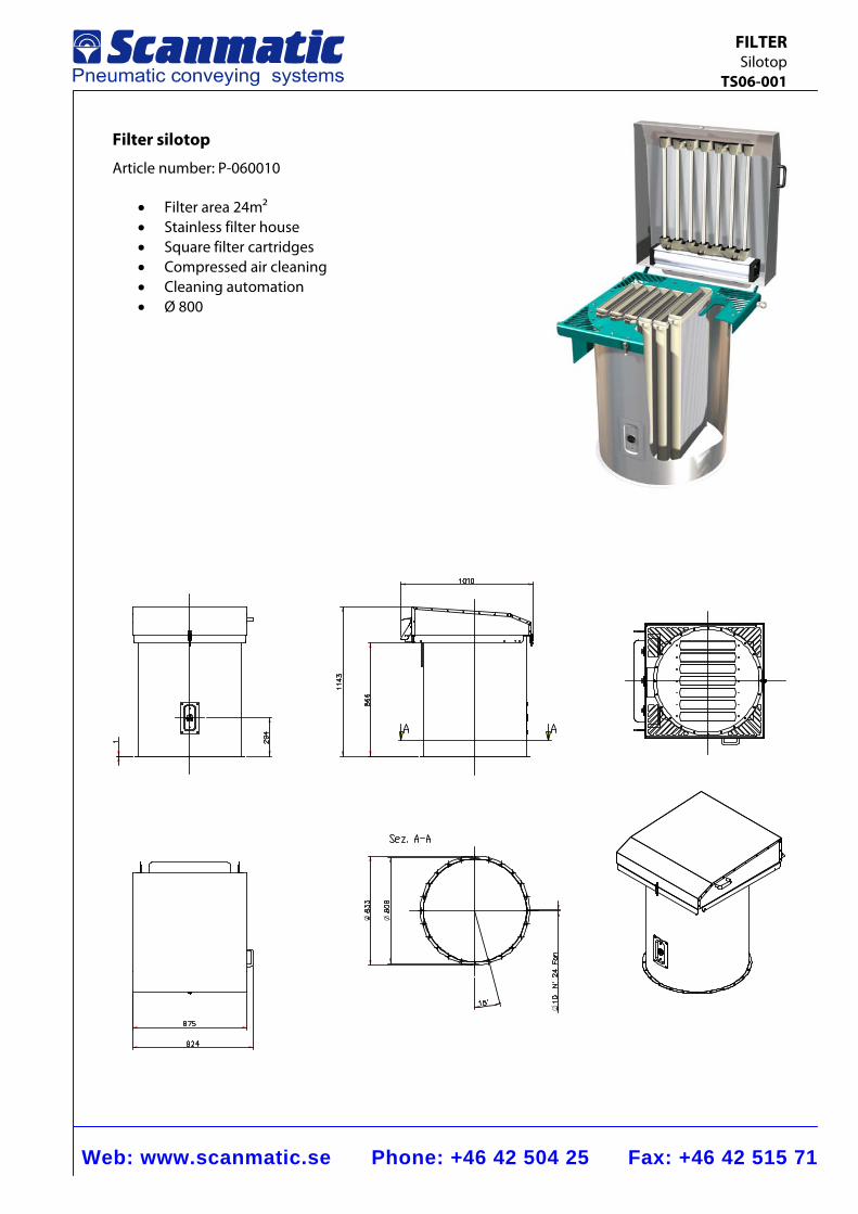
Filter silotop
Article number: P-060010
• Filter area 24m2 • Stainless filter house • Square filter cartridges • Compressed air cleaning • Cleaning automation • Ø 800
Web: www.scanmatic.se Phone: +46 42 504 25 Fax: +46 42 515 71
FILTER With fan TS06-002
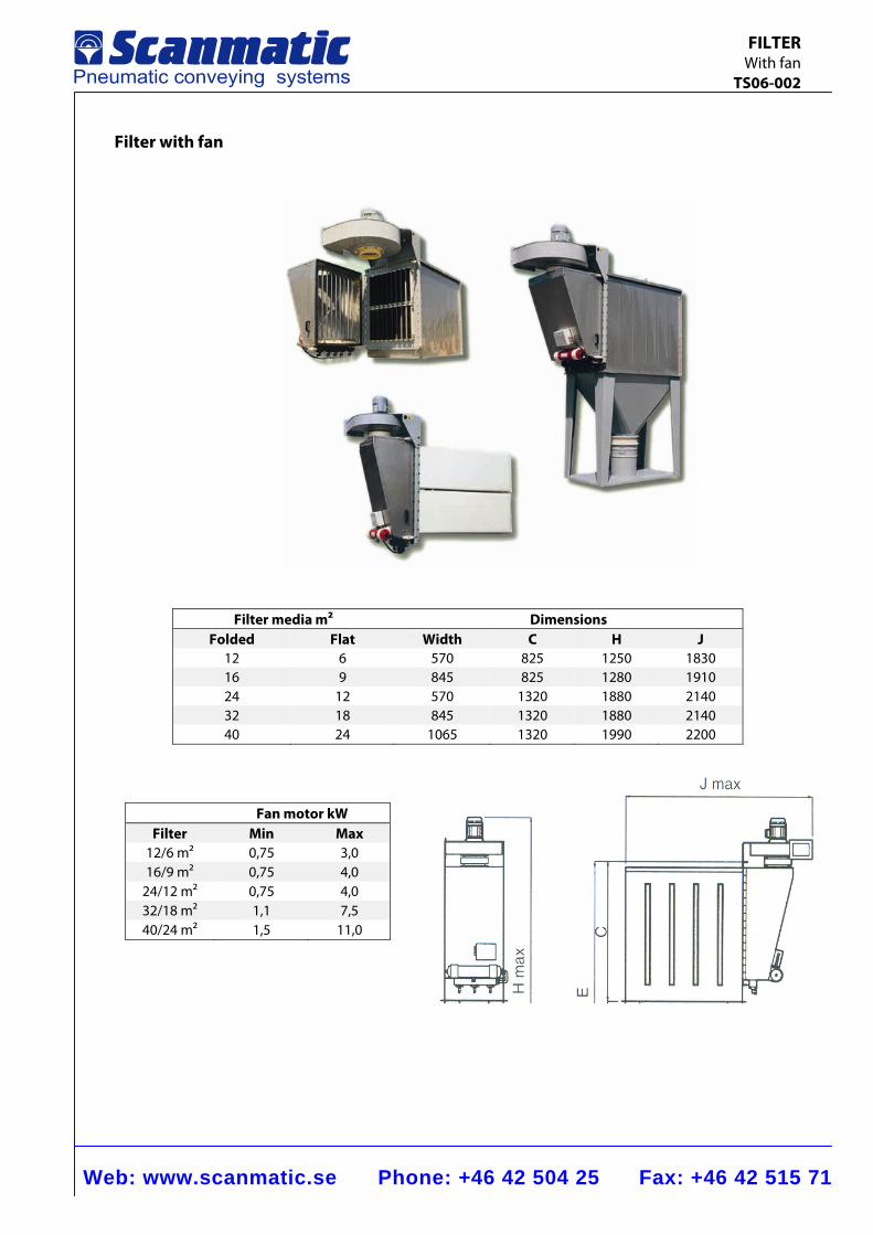
Filter with fan
Filter media m2 Dimensions Folded Flat Width C H J
12 6 570 825 1250 1830 16 9 845 825 1280 1910 24 12 570 1320 1880 2140 32 18 845 1320 1880 2140 40 24 1065 1320 1990 2200
Fan motor kW Filter Min Max
12/6 m2 0,75 3,0 16/9 m2 0,75 4,0
24/12 m2 0,75 4,0 32/18 m2 1,1 7,5 40/24 m2 1,5 11,0
Web: www.scanmatic.se Phone: +46 42 504 25 Fax: +46 42 515 71
SILOAIR FILTER TS06-003
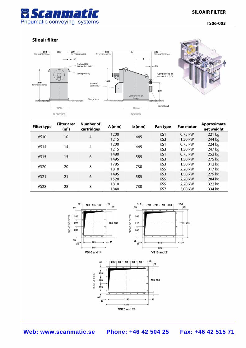
Siloair filter
2050for maintenance
Lifting eye (4)
Removableinspection hatch
silencer(optional)
Flange level
1482
FlangeFlange
Centrum line onflange
Compressed airconnection (½")
870
FRONT VIEW SIDE VIEW
Control unit
500for maintenance
A500for maintenance
500for maintenance
765500for maintenance
b
75
110
Filter type Filter area
(m2) Number of cartridges A (mm) b (mm) Fan type Fan motor
Approximate net weight
VS10 10 4 12001215 445 KS1
KS3 0,75 kW 1,50 kW
221 kg244 kg
VS14 14 4 12001215 445
KS1KS3
0,75 kW 1,50 kW
224 kg247 kg
VS15 15 6 14801495 585 KS1
KS3 0,75 kW 1,50 kW
252 kg275 kg
VS20 20 8 17851810 730 KS3
KS5 1,50 kW 2,20 kW
312 kg317 kg
VS21 21 6 14951520 585
KS3KS5
1,50 kW 2,20 kW
279 kg284 kg
VS28 28 8 18101840 730 KS5
KS7 2,20 kW 3,00 kW
322 kg334 kg
205
225
205
35
85
40 4035
180 175 180
765 835
575
645
35
85
3585
225
205
205
8547,5
200 200 200 20047,5
35
765 835
35855
925
VS15 and 21VS10 and14
225
205
205
85
35
85
205200205200205 8535
765 835
351145
1215
VS20 and 28
FRO
NT
OF
FILT
ER
FRO
NT
OF
FILT
ER
FRO
NT
OF
FILT
ER
Web: www.scanmatic.se Phone: +46 42 504 25 Fax: +46 42 515 71
STAND ALONE FILTER TS06-004
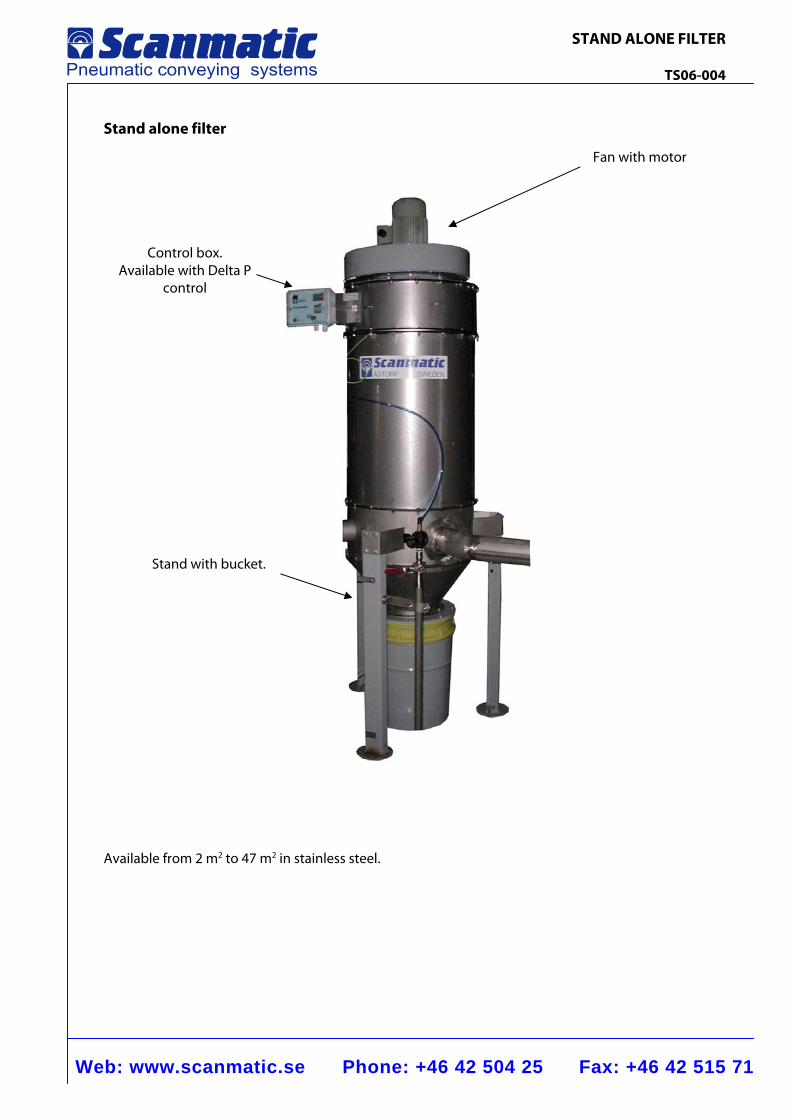
Stand alone filter
Available from 2 m2 to 47 m2 in stainless steel.
Control box. Available with Delta P
control
Stand with bucket.
Fan with motor
Web: www.scanmatic.se Phone: +46 42 504 25 Fax: +46 42 515 71
FILTER VIBRATION CLEANING WITH FAN TS06-005
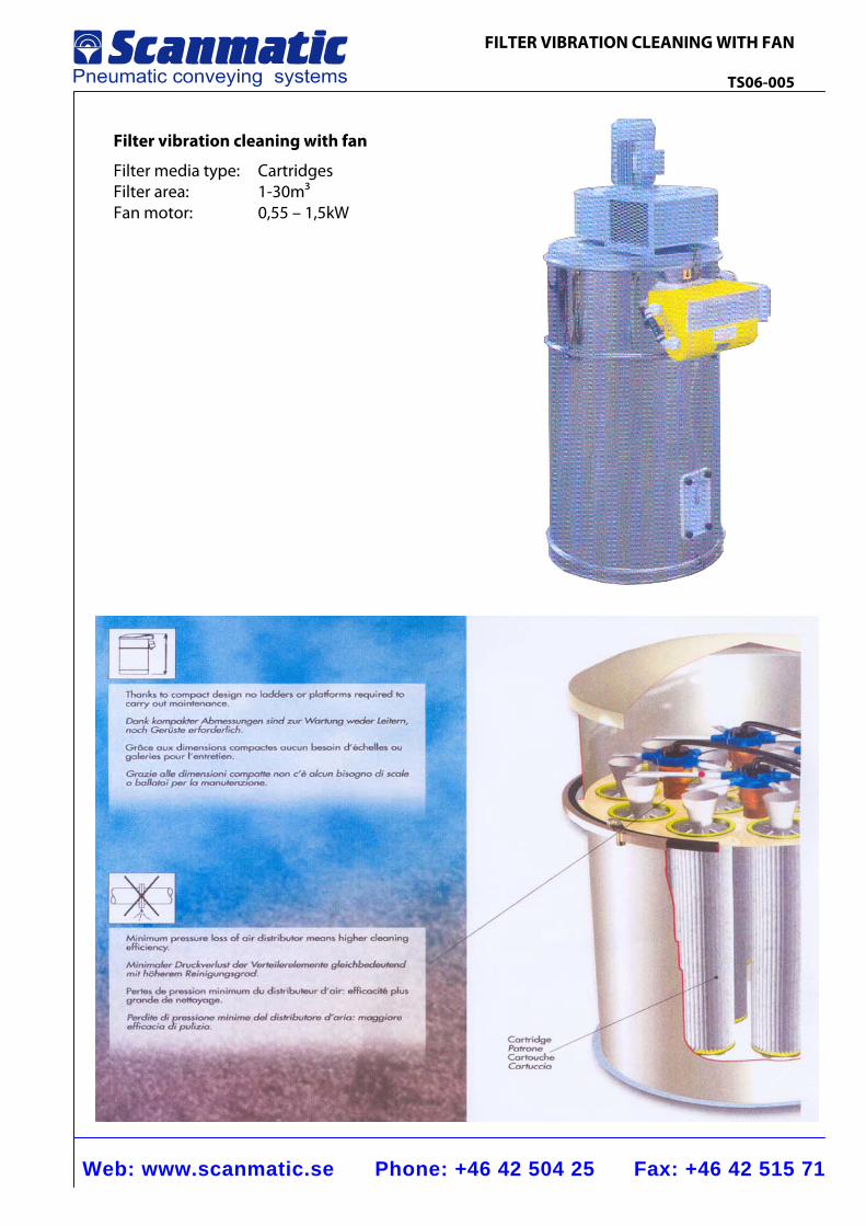
Filter vibration cleaning with fan
Filter media type: Cartridges Filter area: 1-30m3 Fan motor: 0,55 – 1,5kW
Web: www.scanmatic.se Phone: +46 42 504 25 Fax: +46 42 515 71
FILTER DCE125F TS06-006
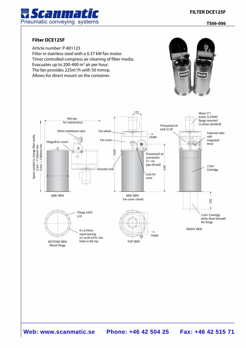
Filter DCE125F
Article number: P-801125 Filter in stainless steel with a 0.37 kW fan motor. Timer controlled compress air cleaning of filter media. Evacuates up to 200-400 m3 air per hour. The fan provides 225m3/h with 50 mmvp. Allows for direct mount on the container.
������
20mm membrane valve
Hinges(Fan cover)
Outlet
122
235
SIDE VIEW
FRONT VIEW
TOP VIEW
900 minfor maintenance
1020
Fan wheel
Fan cover
Excenter lock
SIDE VIEWFan cover closed
Pressurised airtank (2.4l)
Motor (71frame, 0,37kW)flange mounted(3 phase standard)
Outlet
648
Pressurised airconnection(½” int.pipe thread)
Lock forcoverSp
ace
need
ed to
cha
nge
filte
r m
edia
.2,
5m²�
=115
0mm
min
3,6m
²�=
1380
mm
min
BOTTOM VIEWMount flange
Flange ø365y/d
8 x ø10mmequal spacingon circle ø345, twoholes in the top
3,6m²� Cartridgesticks down beneaththe flange
2,5m²�
Cartridge
Solenoid valvewithintegratedtimer
VALVES
Web: www.scanmatic.se Phone: +46 42 504 25 Fax: +46 42 515 71
BUTTERFLY VALVE TS07-001
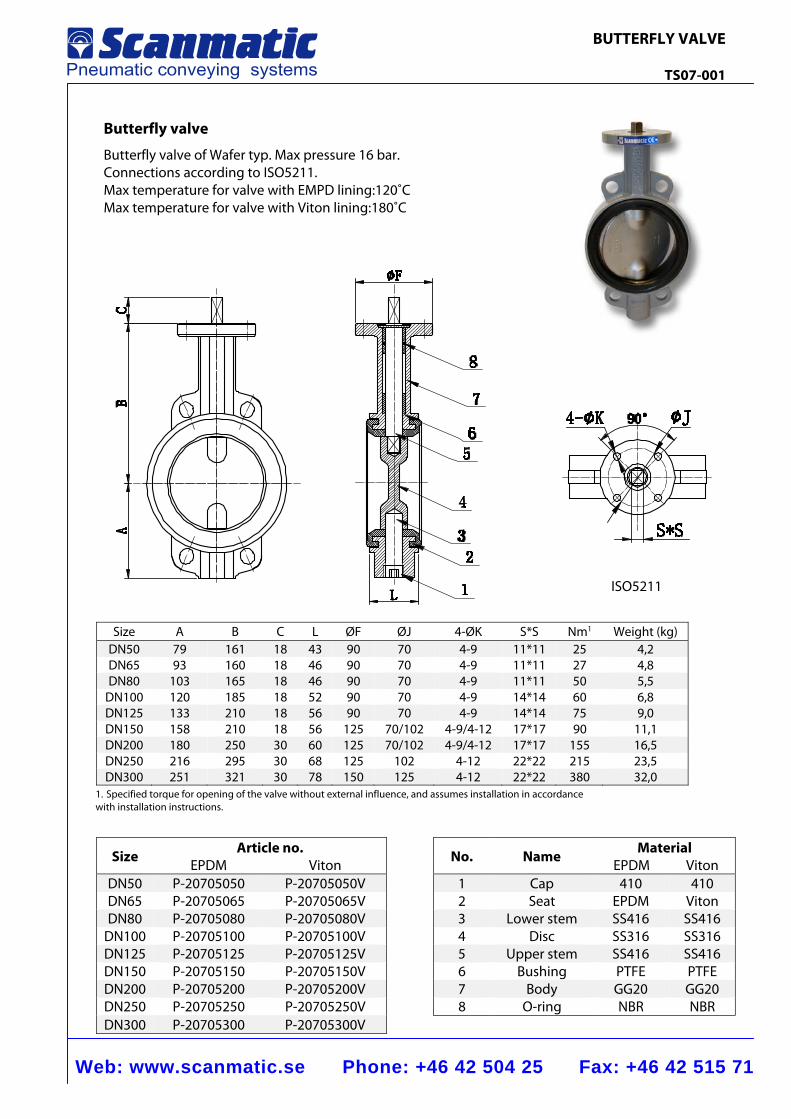
Butterfly valve
Butterfly valve of Wafer typ. Max pressure 16 bar. Connections according to ISO5211. Max temperature for valve with EMPD lining:120˚C Max temperature for valve with Viton lining:180˚C
Size Article no.
No. Name Material EPDM Viton EPDM Viton
DN50 P-20705050 P-20705050V 1 Cap 410 410 DN65 P-20705065 P-20705065V 2 Seat EPDM Viton DN80 P-20705080 P-20705080V 3 Lower stem SS416 SS416
DN100 P-20705100 P-20705100V 4 Disc SS316 SS316 DN125 P-20705125 P-20705125V 5 Upper stem SS416 SS416 DN150 P-20705150 P-20705150V 6 Bushing PTFE PTFE DN200 P-20705200 P-20705200V 7 Body GG20 GG20 DN250 P-20705250 P-20705250V 8 O-ring NBR NBR DN300 P-20705300 P-20705300V
Size A B C L ØF ØJ 4-ØK S*S Nm1 Weight (kg) DN50 79 161 18 43 90 70 4-9 11*11 25 4,2 DN65 93 160 18 46 90 70 4-9 11*11 27 4,8 DN80 103 165 18 46 90 70 4-9 11*11 50 5,5
DN100 120 185 18 52 90 70 4-9 14*14 60 6,8 DN125 133 210 18 56 90 70 4-9 14*14 75 9,0 DN150 158 210 18 56 125 70/102 4-9/4-12 17*17 90 11,1DN200 180 250 30 60 125 70/102 4-9/4-12 17*17 155 16,5DN250 216 295 30 68 125 102 4-12 22*22 215 23,5DN300 251 321 30 78 150 125 4-12 22*22 380 32,0
ISO5211
1. Specified torque for opening of the valve without external influence, and assumes installation in accordance with installation instructions.
Web: www.scanmatic.se Phone: +46 42 504 25 Fax: +46 42 515 71
BUTTERFLY VALVE Lug TS07-018
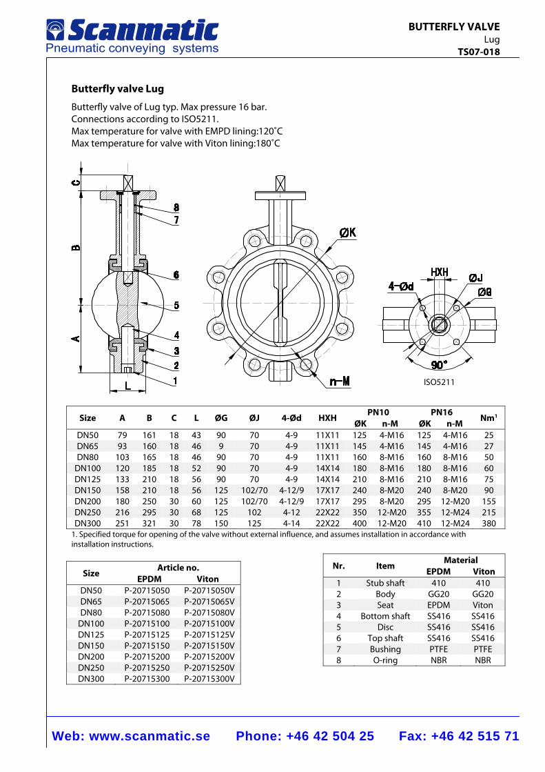
Butterfly valve Lug
Butterfly valve of Lug typ. Max pressure 16 bar. Connections according to ISO5211. Max temperature for valve with EMPD lining:120˚C Max temperature for valve with Viton lining:180˚C
ISO5211
Size A B C L ØG ØJ 4-Ød HXH PN10
ØK n-M PN16
ØK n-M Nm1
DN50 79 161 18 43 90 70 4-9 11X11 125 4-M16 125 4-M16 25DN65 93 160 18 46 9 70 4-9 11X11 145 4-M16 145 4-M16 27DN80 103 165 18 46 90 70 4-9 11X11 160 8-M16 160 8-M16 50
DN100 120 185 18 52 90 70 4-9 14X14 180 8-M16 180 8-M16 60DN125 133 210 18 56 90 70 4-9 14X14 210 8-M16 210 8-M16 75DN150 158 210 18 56 125 102/70 4-12/9 17X17 240 8-M20 240 8-M20 90DN200 180 250 30 60 125 102/70 4-12/9 17X17 295 8-M20 295 12-M20 155DN250 216 295 30 68 125 102 4-12 22X22 350 12-M20 355 12-M24 215DN300 251 321 30 78 150 125 4-14 22X22 400 12-M20 410 12-M24 380
1. Specified torque for opening of the valve without external influence, and assumes installation in accordance with installation instructions.
Nr. Item Material
EPDM Viton 1 Stub shaft 410 4102 Body GG20 GG203 Seat EPDM Viton4 Bottom shaft SS416 SS4165 Disc SS416 SS4166 Top shaft SS416 SS4167 Bushing PTFE PTFE8 O-ring NBR NBR
Size Article no. EPDM Viton
DN50 P-20715050 P-20715050VDN65 P-20715065 P-20715065VDN80 P-20715080 P-20715080V
DN100 P-20715100 P-20715100VDN125 P-20715125 P-20715125VDN150 P-20715150 P-20715150VDN200 P-20715200 P-20715200VDN250 P-20715250 P-20715250VDN300 P-20715300 P-20715300V
Web: www.scanmatic.se Phone: +46 42 504 25 Fax: +46 42 515 71
BUTTERFLY VALVE Metal sealing TS07-010
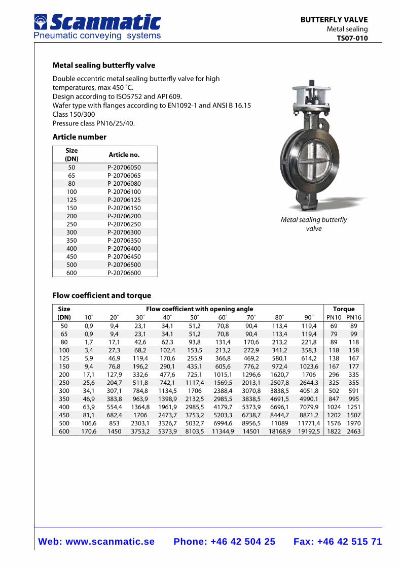
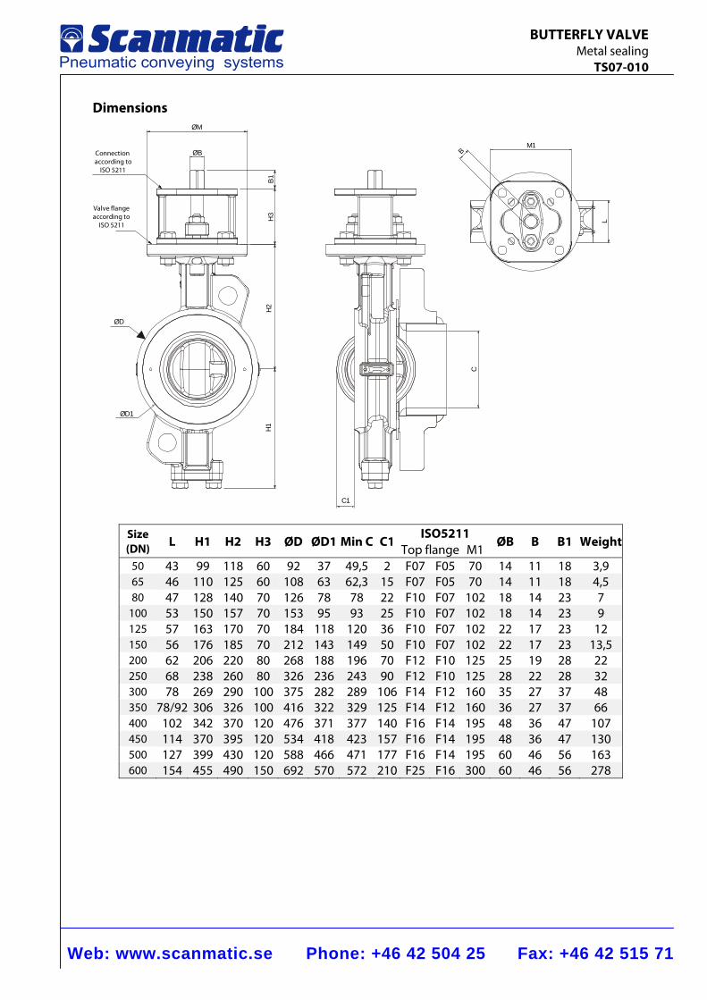
Metal sealing butterfly valve
Double eccentric metal sealing butterfly valve for high temperatures, max 450 ˚C. Design according to ISO5752 and API 609. Wafer type with flanges according to EN1092-1 and ANSI B 16.15 Class 150/300 Pressure class PN16/25/40.
Article number
Size (DN) Article no.
50 P-20706050 65 P-20706065 80 P-20706080
100 P-20706100 125 P-20706125 150 P-20706150 200 P-20706200 250 P-20706250 300 P-20706300 350 P-20706350 400 P-20706400 450 P-20706450 500 P-20706500 600 P-20706600
Flow coefficient and torque
Size (DN)
Flow coefficient with opening angle Torque10˚ 20˚ 30˚ 40˚ 50˚ 60˚ 70˚ 80˚ 90˚ PN10 PN16
50 0,9 9,4 23,1 34,1 51,2 70,8 90,4 113,4 119,4 69 8965 0,9 9,4 23,1 34,1 51,2 70,8 90,4 113,4 119,4 79 9980 1,7 17,1 42,6 62,3 93,8 131,4 170,6 213,2 221,8 89 118
100 3,4 27,3 68,2 102,4 153,5 213,2 272,9 341,2 358,3 118 158125 5,9 46,9 119,4 170,6 255,9 366,8 469,2 580,1 614,2 138 167150 9,4 76,8 196,2 290,1 435,1 605,6 776,2 972,4 1023,6 167 177200 17,1 127,9 332,6 477,6 725,1 1015,1 1296,6 1620,7 1706 296 335250 25,6 204,7 511,8 742,1 1117,4 1569,5 2013,1 2507,8 2644,3 325 355300 34,1 307,1 784,8 1134,5 1706 2388,4 3070,8 3838,5 4051,8 502 591350 46,9 383,8 963,9 1398,9 2132,5 2985,5 3838,5 4691,5 4990,1 847 995400 63,9 554,4 1364,8 1961,9 2985,5 4179,7 5373,9 6696,1 7079,9 1024 1251450 81,1 682,4 1706 2473,7 3753,2 5203,3 6738,7 8444,7 8871,2 1202 1507500 106,6 853 2303,1 3326,7 5032,7 6994,6 8956,5 11089 11771,4 1576 1970600 170,6 1450 3753,2 5373,9 8103,5 11344,9 14501 18168,9 19192,5 1822 2463
Metal sealing butterfly valve
Web: www.scanmatic.se Phone: +46 42 504 25 Fax: +46 42 515 71
BUTTERFLY VALVE Metal sealing TS07-010
15
5
16
17
9
8
7
14
1
6
1011
1213
2
3
418
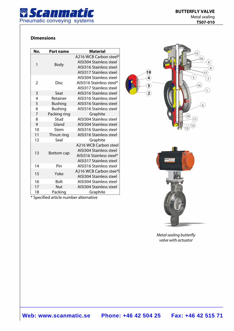
Dimensions
No. Part name Material
A216 WCB Carbon steel*
1 Body AISI304 Stainless steel AISI316 Stainless steel
AISI317 Stainless steel AISI304 Stainless steel
2 Disc AISI316 Stainless steel* AISI317 Stainless steel
3 Seat AISI316 Stainless steel 4 Retainer AISI316 Stainless steel 5 Bushing AISI316 Stainless steel 6 Bushing AISI316 Stainless steel 7 Packing ring Graphite 8 Stud AISI304 Stainless steel 9 Gland AISI304 Stainless steel
10 Stem AISI316 Stainless steel 11 Thrust ring AISI316 Stainless steel 12 Seal Graphite
A216 WCB Carbon steel
13 Bottom cap AISI304 Stainless steel AISI316 Stainless steel*
AISI317 Stainless steel 14 Pin AISI316 Stainless steel
15 Yoke A216 WCB Carbon stee*l
AISI304 Stainless steel 16 Bolt AISI304 Stainless steel 17 Nut AISI304 Stainless steel 18 Packing Graphite
* Specified article number alternative
Metal sealing butterfly valve with actuator
Web: www.scanmatic.se Phone: +46 42 504 25 Fax: +46 42 515 71
BUTTERFLY VALVE Metal sealing TS07-010
Dimensions
M1B
L
C1
C
ØM
ØB
B1H
3H2
H1
ØD1
ØD
Connectionaccording to
ISO 5211
Valve flangeaccording to
ISO 5211
Size (DN) L H1 H2 H3 ØD ØD1 Min C C1
ISO5211 ØB B B1 Weight
Top flange M150 43 99 118 60 92 37 49,5 2 F07 F05 70 14 11 18 3,9 65 46 110 125 60 108 63 62,3 15 F07 F05 70 14 11 18 4,5 80 47 128 140 70 126 78 78 22 F10 F07 102 18 14 23 7
100 53 150 157 70 153 95 93 25 F10 F07 102 18 14 23 9 125 57 163 170 70 184 118 120 36 F10 F07 102 22 17 23 12 150 56 176 185 70 212 143 149 50 F10 F07 102 22 17 23 13,5 200 62 206 220 80 268 188 196 70 F12 F10 125 25 19 28 22 250 68 238 260 80 326 236 243 90 F12 F10 125 28 22 28 32 300 78 269 290 100 375 282 289 106 F14 F12 160 35 27 37 48 350 78/92 306 326 100 416 322 329 125 F14 F12 160 36 27 37 66 400 102 342 370 120 476 371 377 140 F16 F14 195 48 36 47 107 450 114 370 395 120 534 418 423 157 F16 F14 195 48 36 47 130 500 127 399 430 120 588 466 471 177 F16 F14 195 60 46 56 163 600 154 455 490 150 692 570 572 210 F25 F16 300 60 46 56 278
Web: www.scanmatic.se Phone: +46 42 504 25 Fax: +46 42 515 71
PNEUMATIC ACTUATORS Double acting TS07-005
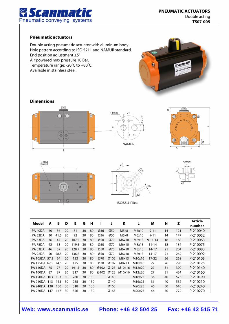
Pneumatic actuators
Double acting pneumatic actuator with aluminum body. Hole pattern according to ISO 5211 and NAMUR standard. End position adjustment ±5˚ Air powered max pressure 10 Bar. Temperature range: -20˚C to +80˚C. Available in stainless steel.
Dimensions
NAMUR
ISO5211 Fläns
RP EN S SOI UT RN IZE ETT D
A
NAMUR4
4
12
M6
4xK
4xL
M
45°
J l
G
H
4-M5x8NAMUR
Z
324-M5x8 24
2-G
1/4"
A B
N
E
D
Model A B D E G H I J K L M N Z Article number
PA 40DA 40 36 20 81 30 80 Ø36 Ø50 M5x8 M6x10 9-11 14 121 P-210040PA 52DA 30 41,5 20 92 30 80 Ø36 Ø50 M5x8 M6x10 9-11 14 147 P-210052PA 63DA 36 47 20 107,5 30 80 Ø50 Ø70 M6x10 M8x13 9-11-14 18 168 P-210063PA 75DA 42 53 20 119,5 30 80 Ø50 Ø70 M6x10 M8x13 11-14 18 184 P-210075PA 83DA 46 57 20 128,7 30 80 Ø50 Ø70 M6x10 M8x13 14-17 21 204 P-210083PA 92DA 50 58,5 20 136,8 30 80 Ø50 Ø70 M6x10 M8x13 14-17 21 262 P-210092
PA 105DA 57,5 64 20 153 30 80 Ø70 Ø102 M8x13 M10x16 17-22 26 268 P-210105PA 125DA 67,5 74,5 20 175 30 80 Ø70 Ø102 M8x13 M10x16 22 26 296 P-210125PA 140DA 75 77 20 191,5 30 80 Ø102 Ø125 M10x16 M12x20 27 31 390 P-210140PA 160DA 87 87 20 217 30 80 Ø102 Ø125 M10x16 M12x20 27 31 454 P-210160PA 190DA 103 103 30 260 30 130 Ø140 M16x25 36 40 525 P-210190PA 210DA 113 113 30 285 30 130 Ø140 M16x25 36 40 532 P-210210PA 240DA 130 130 30 318 30 130 Ø165 M20x25 46 50 610 P-210240PA 270DA 147 147 30 356 30 130 Ø165 M20x25 46 50 722 P-210270
Web: www.scanmatic.se Phone: +46 42 504 25 Fax: +46 42 515 71
PNEUMATIC ACTUATORS Double acting TS07-005
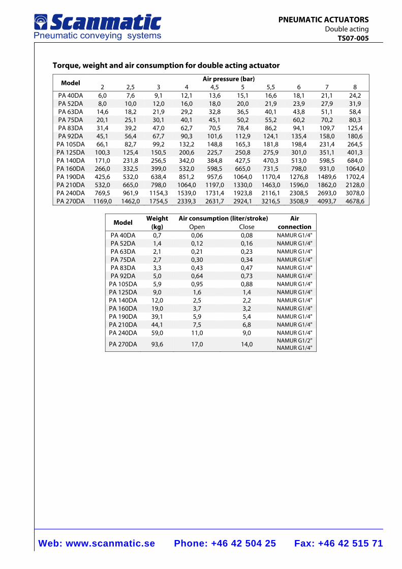
Torque, weight and air consumption for double acting actuator
Model Air pressure (bar)2 2,5 3 4 4,5 5 5,5 6 7 8
PA 40DA 6,0 7,6 9,1 12,1 13,6 15,1 16,6 18,1 21,1 24,2PA 52DA 8,0 10,0 12,0 16,0 18,0 20,0 21,9 23,9 27,9 31,9PA 63DA 14,6 18,2 21,9 29,2 32,8 36,5 40,1 43,8 51,1 58,4PA 75DA 20,1 25,1 30,1 40,1 45,1 50,2 55,2 60,2 70,2 80,3PA 83DA 31,4 39,2 47,0 62,7 70,5 78,4 86,2 94,1 109,7 125,4PA 92DA 45,1 56,4 67,7 90,3 101,6 112,9 124,1 135,4 158,0 180,6
PA 105DA 66,1 82,7 99,2 132,2 148,8 165,3 181,8 198,4 231,4 264,5PA 125DA 100,3 125,4 150,5 200,6 225,7 250,8 275,9 301,0 351,1 401,3PA 140DA 171,0 231,8 256,5 342,0 384,8 427,5 470,3 513,0 598,5 684,0PA 160DA 266,0 332,5 399,0 532,0 598,5 665,0 731,5 798,0 931,0 1064,0PA 190DA 425,6 532,0 638,4 851,2 957,6 1064,0 1170,4 1276,8 1489,6 1702,4PA 210DA 532,0 665,0 798,0 1064,0 1197,0 1330,0 1463,0 1596,0 1862,0 2128,0PA 240DA 769,5 961,9 1154,3 1539,0 1731,4 1923,8 2116,1 2308,5 2693,0 3078,0PA 270DA 1169,0 1462,0 1754,5 2339,3 2631,7 2924,1 3216,5 3508,9 4093,7 4678,6
Model Weight (kg)
Air consumption (liter/stroke) Air connection Open Close
PA 40DA 0,7 0,06 0,08 NAMUR G1/4" PA 52DA 1,4 0,12 0,16 NAMUR G1/4" PA 63DA 2,1 0,21 0,23 NAMUR G1/4" PA 75DA 2,7 0,30 0,34 NAMUR G1/4" PA 83DA 3,3 0,43 0,47 NAMUR G1/4" PA 92DA 5,0 0,64 0,73 NAMUR G1/4"
PA 105DA 5,9 0,95 0,88 NAMUR G1/4" PA 125DA 9,0 1,6 1,4 NAMUR G1/4" PA 140DA 12,0 2,5 2,2 NAMUR G1/4" PA 160DA 19,0 3,7 3,2 NAMUR G1/4" PA 190DA 39,1 5,9 5,4 NAMUR G1/4" PA 210DA 44,1 7,5 6,8 NAMUR G1/4" PA 240DA 59,0 11,0 9,0 NAMUR G1/4"
PA 270DA 93,6 17,0 14,0 NAMUR G1/2" NAMUR G1/4"
Web: www.scanmatic.se Phone: +46 42 504 25 Fax: +46 42 515 71
PNEUMATIC ACTUATORS Double acting TS07-005
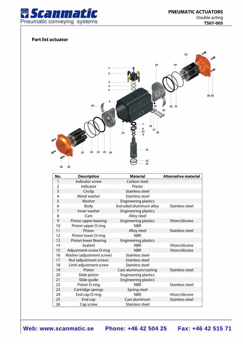
Part list actuator
1
2
345
6
7
8109
11
1213
14
15
16
1718
19
202122
24
23
25 26
22 19212423
20
2526
No. Description Material Alternative material 1 Indicator screw Carbon steel 2 Indicator Plastic 3 Circlip Stainless steel 4 Metal washer Stainless steel 5 Washer Engineering plastics 6 Body Extruded aluminum alloy Stainless steel 7 Inner washer Engineering plastics 8 Cam Alloy steel 9 Pinion upper bearing Engineering plastics Viton/silicone
10 Pinion upper O-ring NBR 11 Pinion Alloy steel Stainless steel 12 Pinion lower O-ring NBR 13 Pinion lower Bearing Engineering plastics 14 Sealant NBR Viton/silicone 15 Adjustment screw O-ring NBR Viton/silicone 16 Washer (adjustment screw) Stainless steel 17 Nut (adjustment screw) Stainless steel 18 Limit adjustment screw Stainless steel 19 Piston Cast aluminum/casting Stainless steel 20 Slide piston Engineering plastics 21 Slide guide Engineering plastics 22 Piston O-ring NBR Stainless steel 23 Cartridge springs Spring steel 24 End cap O-ring NBR Viton/silicone 25 End cap Cast aluminum Stainless steel 26 Cap screw Stainless steel
Web: www.scanmatic.se Phone: +46 42 504 25 Fax: +46 42 515 71
ELECTRIC ACTUATOR TS07-007
PRO 020
PRO 080
PRO 040
N
F1F2
F3
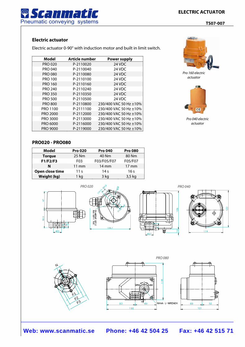
Electric actuator
Electric actuator 0-90° with induction motor and built in limit switch.
Model Article number Power supplyPRO 020 P-2110020 24 VDCPRO 040 P-2110040 24 VDCPRO 080 P-2110080 24 VDCPRO 100 P-2110100 24 VDCPRO 160 P-2110160 24 VDCPRO 240 P-2110240 24 VDCPRO 350 P-2110350 24 VDCPRO 500 P-2110500 24 VDCPRO 800 P-2110800 230/400 VAC 50 Hz ±10%
PRO 1100 P-2111100 230/400 VAC 50 Hz ±10%PRO 2000 P-2112000 230/400 VAC 50 Hz ±10%PRO 3000 P-2113000 230/400 VAC 50 Hz ±10%PRO 6000 P-2116000 230/400 VAC 50 Hz ±10%PRO 9000 P-2119000 230/400 VAC 50 Hz ±10%
PRO020 - PRO080
Model Pro 020 Pro 040 Pro 080Torque 25 Nm 40 Nm 80 Nm
F1/F2/F3 F03 F03/F05/F07 F05/F07 N 11 mm 14 mm 17 mm
Open close time 11 s 14 s 16 s Weight (kg) 1 kg 3 kg 3,5 kg
Pro 160 electric actuator
Pro 040 electric actuator
Web: www.scanmatic.se Phone: +46 42 504 25 Fax: +46 42 515 71
ELECTRIC ACTUATOR TS07-007
4 - AxB
C
2-PF3/4
YX
Z
H
GDEF
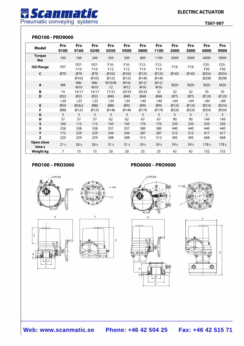
PRO100 - PRO9000
Model Pro
0100 Pro
0160 Pro
0240 Pro
0350 Pro
0500 Pro
0800 Pro
1100 Pro
2000 Pro
3000 Pro
6000 Pro
9000 Torque
Nm 100 160 240 350 500 800 1100 2000 3000 6000 9000
ISO flange F07 F07-F10
F07-F10
F10-F12
F10-F12
F12-F14
F12-F14
F16 F16 F25-F30
F25-F30
C Ø70 Ø70 Ø70 Ø102 Ø102 Ø125 Ø125 Ø165 Ø165 Ø254 Ø254 Ø102 Ø102 Ø125 Ø125 Ø140 Ø140 Ø298 Ø298
A M8 M8/ M10
M8/ M10
M10/M12
M10/ M12
M12/ M16
M12/ M16 M20 M20 M20 M20
B 14 14/17 14/17 17/21 20/25 20/25 32 32 32 35 35 D Ø22 Ø25 Ø25 Ø40 Ø40 Ø48 Ø48 Ø75 Ø75 Ø120 Ø120 □20 □23 □23 □34 □34 □40 □40 □64 □64 □84 □84
E Ø50 Ø58,5 Ø80 Ø80 Ø95 Ø95 Ø95 Ø135 Ø135 Ø216 Ø216 F Ø88 Ø125 Ø125 Ø148 Ø148 Ø178 Ø178 Ø226 Ø226 Ø350 Ø350 G 3 3 3 3 3 3 3 5 5 5 5 H 37 57 57 62 62 67 67 90 90 149 149 S 100 115 115 145 145 170 170 250 250 250 250 X 258 338 338 357 357 380 380 440 440 440 440 Y 172 229 229 244 244 287 287 312 312 417 417 Z 220 259 259 288 288 313 313 385 385 668 668
Open close time s
21 s 26 s 26 s 31 s 31 s 39 s 39 s 59 s 59 s 178 s 178 s
Weight kg 7 15 15 20 20 25 25 42 42 152 152
PRO100 – PRO3000 PRO6000 – PRO9000
2-PF3/4
4 - AxB
F1
YX
S
HG
Z
DEF
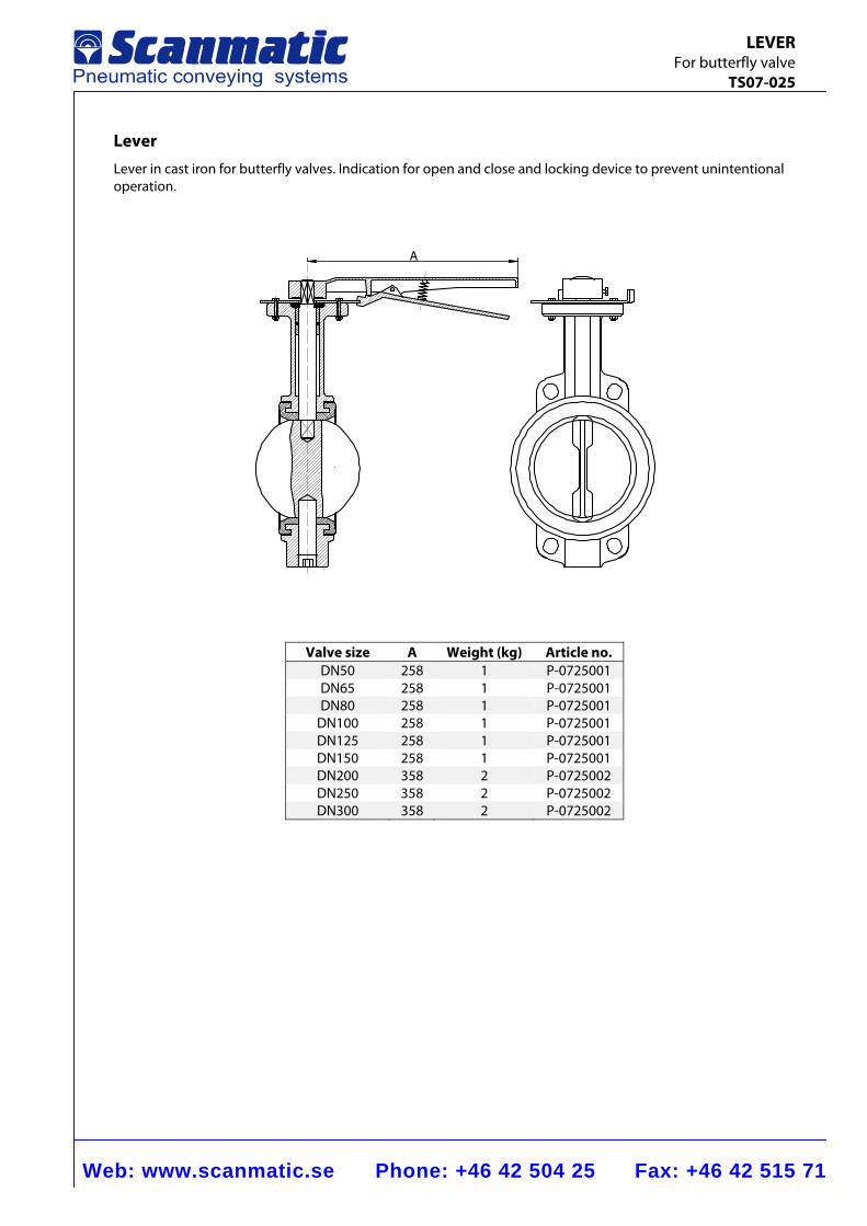
Web: www.scanmatic.se Phone: +46 42 504 25 Fax: +46 42 515 71
LEVER For butterfly valve TS07-025
A
Lever Lever in cast iron for butterfly valves. Indication for open and close and locking device to prevent unintentional operation.
Valve size A Weight (kg) Article no.DN50 258 1 P-0725001DN65 258 1 P-0725001DN80 258 1 P-0725001
DN100 258 1 P-0725001DN125 258 1 P-0725001DN150 258 1 P-0725001DN200 358 2 P-0725002DN250 358 2 P-0725002DN300 358 2 P-0725002
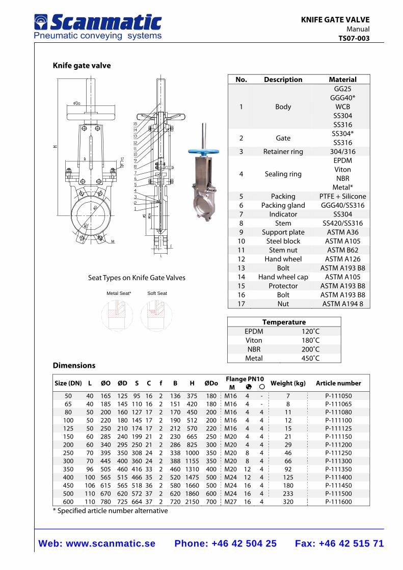
Web: www.scanmatic.se Phone: +46 42 504 25 Fax: +46 42 515 71
KNIFE GATE VALVE Manual TS07-003
Knife gate valve
M
Dimensions
Size (DN) L ØO ØD S C f B H ØDoFlange PN10
M Weight (kg) Article number
50 40 165 125 95 16 2 136 375 180 M16 4 - 7 P-11105065 40 185 145 110 16 2 151 420 180 M16 4 - 8 P-11106580 50 200 160 127 17 2 170 450 200 M16 4 4 11 P-111080
100 50 220 180 145 17 2 190 512 200 M16 4 4 12 P-111100125 50 250 210 174 17 2 212 570 220 M16 4 4 15 P-111125150 60 285 240 199 21 2 230 665 250 M20 4 4 21 P-111150200 60 340 295 250 21 2 286 825 300 M20 4 4 29 P-111200250 70 395 350 308 24 2 338 1000 350 M20 8 4 46 P-111250300 70 445 400 360 24 2 388 1155 350 M20 8 4 66 P-111300350 96 505 460 416 33 2 460 1310 400 M20 12 4 92 P-111350400 100 565 515 466 35 2 520 1475 500 M24 12 4 125 P-111400450 106 615 565 518 36 2 580 1660 500 M24 16 4 180 P-111450500 110 670 620 572 37 2 620 1860 600 M24 16 4 233 P-111500600 110 780 725 664 37 2 720 2150 700 M27 16 4 320 P-111600
* Specified article number alternative
No. Description Material
1 Body
GG25 GGG40*
WCB SS304 SS316
2 Gate SS304* SS316
3 Retainer ring 304/316
4 Sealing ring
EPDM Viton NBR
Metal* 5 Packing PTFE + Silicone6 Packing gland GGG40/SS316 7 Indicator SS304 8 Stem SS420/SS316 9 Support plate ASTM A36
10 Steel block ASTM A105 11 Stem nut ASTM B62 12 Hand wheel ASTM A126 13 Bolt ASTM A193 B8 14 Hand wheel cap ASTM A105 15 Protector ASTM A193 B8 16 Bolt ASTM A193 B8 17 Nut ASTM A194 8
Temperature EPDM 120˚C Viton 180˚C NBR 200˚C
Metal 450˚C
S ea t T yp es on Kni fe G a te Valves
Metal Seat* Soft Seat
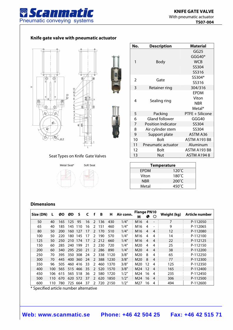
Web: www.scanmatic.se Phone: +46 42 504 25 Fax: +46 42 515 71
KNIFE GATE VALVE With pneumatic actuator TS07-004
Knife gate valve with pneumatic actuator
Dimensions
Size (DN) L ØO ØD S C f B H Air conn. Flange PN10 M
Weight (kg) Article number
50 40 165 125 95 16 2 136 430 1/4" M16 4 - 7 P-11205065 40 185 145 110 16 2 151 460 1/4" M16 4 - 9 P-11206580 50 200 160 127 17 2 170 510 1/4" M16 4 4 12 P-112080
100 50 220 180 145 17 2 190 570 1/4" M16 4 4 14 P-112100125 50 250 210 174 17 2 212 660 1/4" M16 4 4 22 P-112125150 60 285 240 199 21 2 230 720 1/4" M20 4 4 25 P-112150200 60 340 295 250 21 2 286 890 1/4" M20 4 4 38 P-112200250 70 395 350 308 24 2 338 1120 3/8" M20 8 4 65 P-112250300 70 445 400 360 24 2 388 1230 3/8" M20 8 4 77 P-112300350 96 505 460 416 33 2 460 1370 3/8" M20 12 4 125 P-112350400 100 565 515 466 35 2 520 1570 3/8" M24 12 4 165 P-112400450 106 615 565 518 36 2 580 1720 1/2" M24 16 4 235 P-112450500 110 670 620 572 37 2 620 1850 1/2" M24 16 4 306 P-112500600 110 780 725 664 37 2 720 2150 1/2" M27 16 4 494 P-112600
* Specified article number alternative
No. Description Material
1 Body
GG25 GGG40*
WCB SS304 SS316
2 Gate SS304* SS316
3 Retainer ring 304/316
4 Sealing ring
EPDM Viton NBR
Metal* 5 Packing PTFE + Silicone6 Gland follower GGG40 7 Position Indicator SS304 8 Air cylinder stem SS304 9 Support plate ASTM A36
10 Bolt ASTM A193 B8 11 Pneumatic actuator Aluminum 12 Bolt ASTM A193 B8 13 Nut ASTM A194 8
Temperature EPDM 120˚C Viton 180˚C NBR 200˚C
Metal 450˚C
S e a t Ty p es on Knife G a te Valves
Metal Seat* Soft Seat
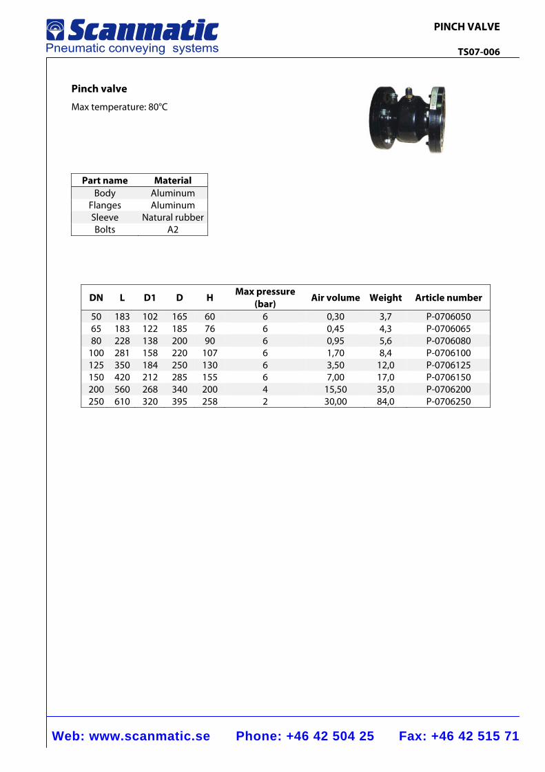
Web: www.scanmatic.se Phone: +46 42 504 25 Fax: +46 42 515 71
PINCH VALVE TS07-006
Pinch valve
Max temperature: 80°C
Part name Material Body Aluminum
Flanges Aluminum Sleeve Natural rubber Bolts A2
DN L D1 D H Max pressure (bar)
Air volume Weight Article number
50 183 102 165 60 6 0,30 3,7 P-0706050 65 183 122 185 76 6 0,45 4,3 P-0706065 80 228 138 200 90 6 0,95 5,6 P-0706080
100 281 158 220 107 6 1,70 8,4 P-0706100 125 350 184 250 130 6 3,50 12,0 P-0706125 150 420 212 285 155 6 7,00 17,0 P-0706150 200 560 268 340 200 4 15,50 35,0 P-0706200 250 610 320 395 258 2 30,00 84,0 P-0706250
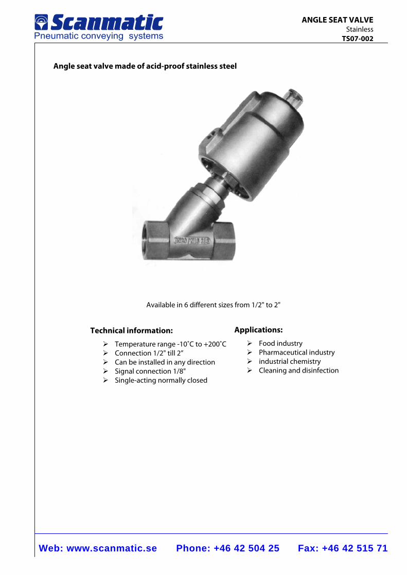
Web: www.scanmatic.se Phone: +46 42 504 25 Fax: +46 42 515 71
ANGLE SEAT VALVE Stainless TS07-002
Angle seat valve made of acid-proof stainless steel
Available in 6 different sizes from 1/2" to 2"
Technical information:
Temperature range -10˚C to +200˚C Connection 1/2" till 2” Can be installed in any direction Signal connection 1/8" Single-acting normally closed
Applications:
Food industry Pharmaceutical industry industrial chemistry Cleaning and disinfection
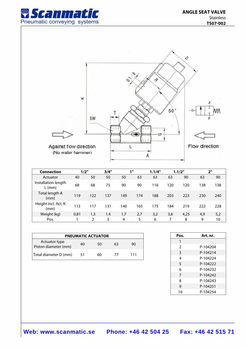
Web: www.scanmatic.se Phone: +46 42 504 25 Fax: +46 42 515 71
ANGLE SEAT VALVE Stainless TS07-002
Connection 1/2" 3/4" 1" 1.1/4" 1.1/2" 2"
Actuator 40 50 50 50 63 63 63 90 63 90 Installation length
L (mm) 68 68 75 90 90 116 120 120 138 138
Total length A (mm) 119 122 137 149 174 188 203 223 230 240
Height incl. Act. K (mm) 113 117 131 140 165 175 184 219 222 228
Weight (kg) 0,81 1,3 1,4 1,7 2,7 3,2 3,6 4,25 4,9 5,2 Pos. 1 2 3 4 5 6 7 8 9 10
PNEUMATIC ACTUATOR Actuator type
Piston diameter (mm) 40 50 63 90
Total diameter D (mm) 51 60 77 111
Pos. Art. nr. 1 2 P-104204 3 P-104214 4 P-104224 5 P-104222 6 P-104232 7 P-104242 8 P-104243 9 P-104251
10 P-104254
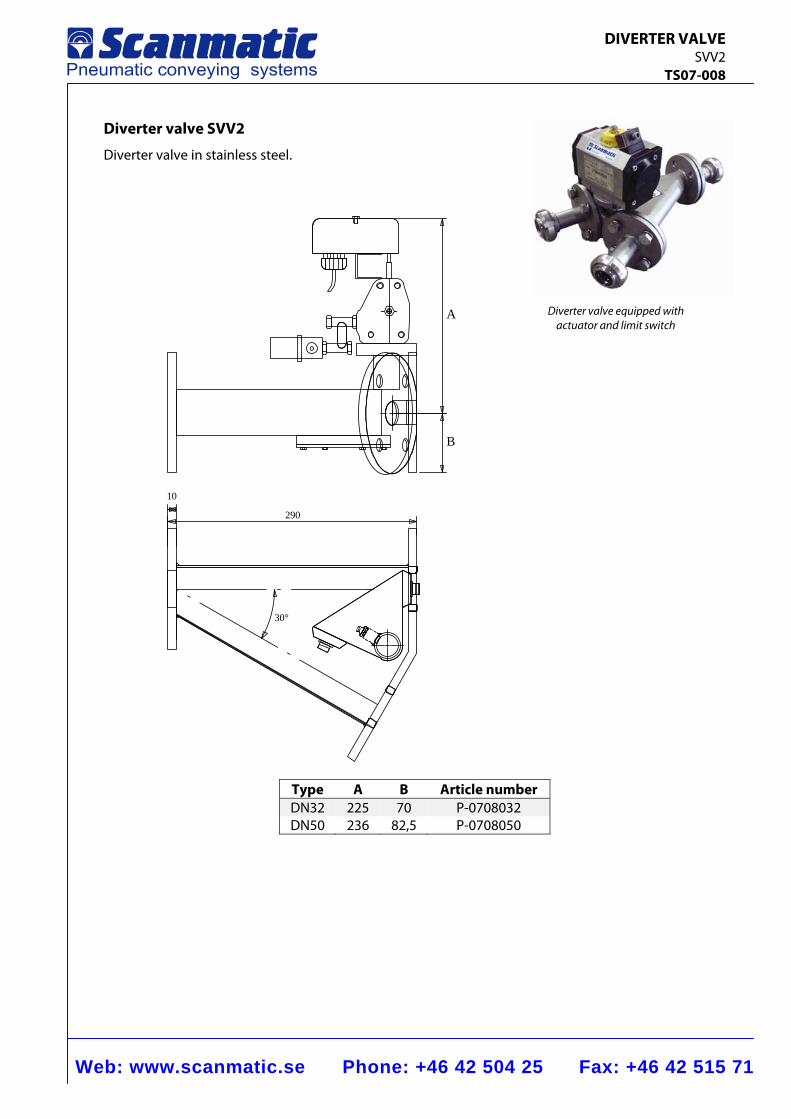
Web: www.scanmatic.se Phone: +46 42 504 25 Fax: +46 42 515 71
DIVERTER VALVE SVV2 TS07-008
Diverter valve SVV2
Diverter valve in stainless steel.
30°
290
10
A
B
Type A B Article number DN32 225 70 P-0708032 DN50 236 82,5 P-0708050
Diverter valve equipped with actuator and limit switch
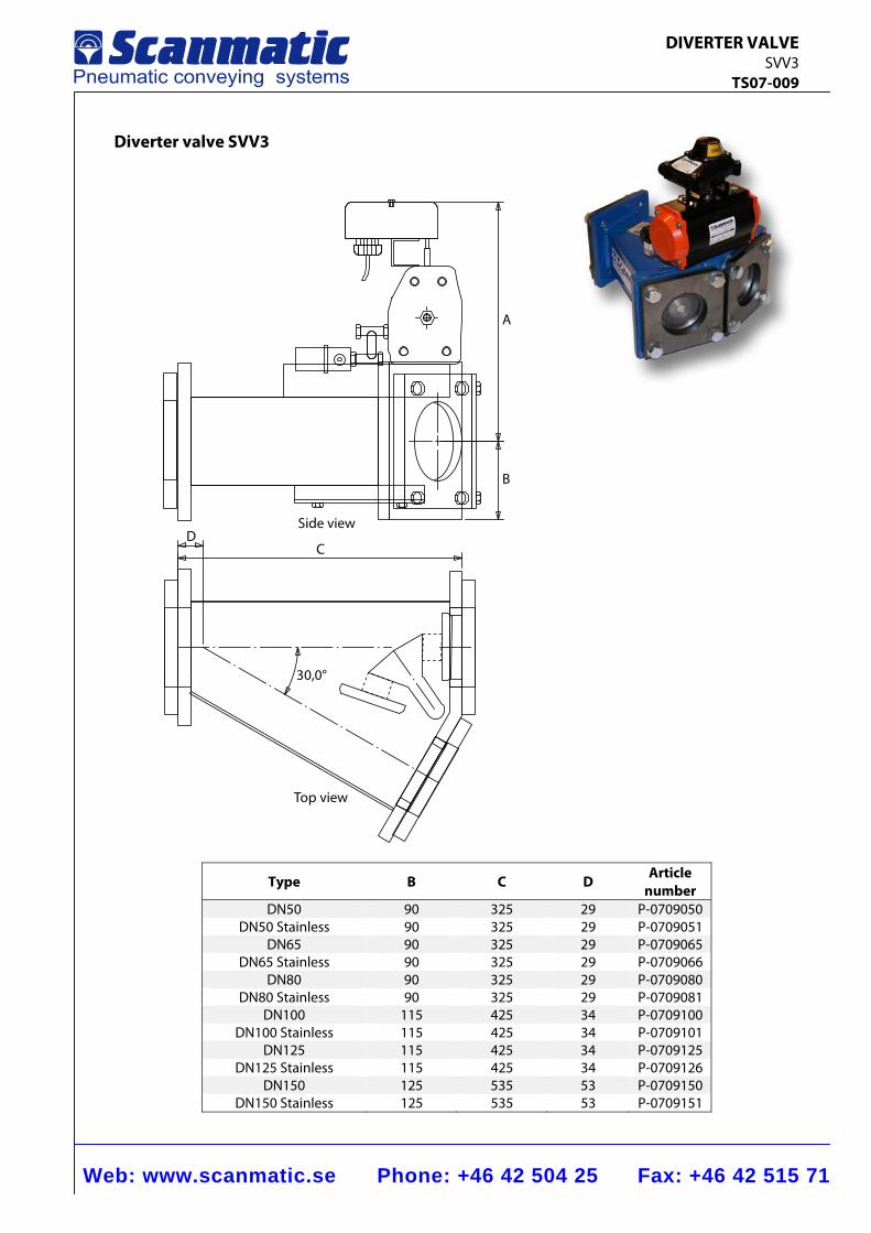
Web: www.scanmatic.se Phone: +46 42 504 25 Fax: +46 42 515 71
DIVERTER VALVE SVV3 TS07-009
Diverter valve SVV3
Top view
30,0°
Side view
B
A
DC
Type B C D Article number
DN50 90 325 29 P-0709050 DN50 Stainless 90 325 29 P-0709051
DN65 90 325 29 P-0709065 DN65 Stainless 90 325 29 P-0709066
DN80 90 325 29 P-0709080 DN80 Stainless 90 325 29 P-0709081
DN100 115 425 34 P-0709100 DN100 Stainless 115 425 34 P-0709101
DN125 115 425 34 P-0709125 DN125 Stainless 115 425 34 P-0709126
DN150 125 535 53 P-0709150 DN150 Stainless 125 535 53 P-0709151
Web: www.scanmatic.se Phone: +46 42 504 25 Fax: +46 42 515 71
DIVERTER VALVE SVV3 TS07-009
Function
The valve is to be built direct into conveying pipe line at distribution from one line to two receiving places or on the contrary from two lines to one common line. The valve is el-pneumatically operated and has two separate cones, which are making tight alternately in each seat. Cones and seats are easily replaceable and centered for an efficient sealing. Solid design, most suitable for wearing goods and resistant against high pressures.
Basic design
Valve house of welded steel plate. Cones sealed by vulcanized rubber tile. Operating axle bearing in greased bush with double O-ring seals. El-pneumatic operation with rotary cylinder and impulse controlled solenoid valve, which means that the valve always keeps its position in cases of current- as well as air failure. Electric-connection: 220 V, 50 Hz, IP 65 Operating air: Working pressure: 600 kPa, ansl R 1/8". Limit switches indicating both positions. Direction indicator. The valves are delivered with weldable connection flanges for conveying pipe lines. External surfaces treated according to Scanmatics standard painting program
Special design
− Manual operation by a lever replacing the el-pneumatic switching equipment − Partially in stainless steel, i. e. valve house internally epoxy coated. Other included parts
of stainless steel SS2333 − Complete stainless design i.e. valve house as well as other included parts of stainless
steel SS2333 alternatively acid proof steel SS2343
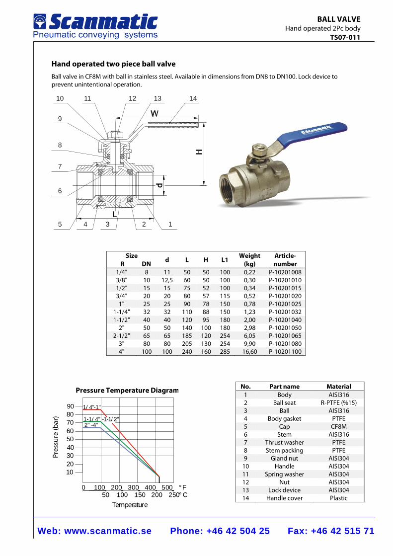
Web: www.scanmatic.se Phone: +46 42 504 25 Fax: +46 42 515 71
BALL VALVE Hand operated 2Pc body TS07-011
8
9
10 11 12 13
7
6
5 4 3 2 1
14
Pressure Temperature Diagram
Temperature
0 100 200 300 400 50050 100 150 200 250
°F°C
908070605040302010
Pres
sure
(bar
) 1-1/4" -1-1/2"
1/4"-1"
2" -4"
Hand operated two piece ball valve Ball valve in CF8M with ball in stainless steel. Available in dimensions from DN8 to DN100. Lock device to prevent unintentional operation.
Size R DN d L H L1
Weight(kg)
Article- number
1/4" 8 11 50 50 100 0,22 P-10201008 3/8" 10 12,5 60 50 100 0,30 P-10201010 1/2" 15 15 75 52 100 0,34 P-10201015 3/4" 20 20 80 57 115 0,52 P-10201020
1" 25 25 90 78 150 0,78 P-10201025 1-1/4" 32 32 110 88 150 1,23 P-10201032 1-1/2" 40 40 120 95 180 2,00 P-10201040
2" 50 50 140 100 180 2,98 P-10201050 2-1/2" 65 65 185 120 254 6,05 P-10201065
3" 80 80 205 130 254 9,90 P-10201080 4" 100 100 240 160 285 16,60 P-10201100
No. Part name Material1 Body AISI3162 Ball seat R-PTFE (%15)3 Ball AISI3164 Body gasket PTFE5 Cap CF8M6 Stem AISI3167 Thrust washer PTFE8 Stem packing PTFE9 Gland nut AISI304
10 Handle AISI30411 Spring washer AISI30412 Nut AISI30413 Lock device AISI30414 Handle cover Plastic
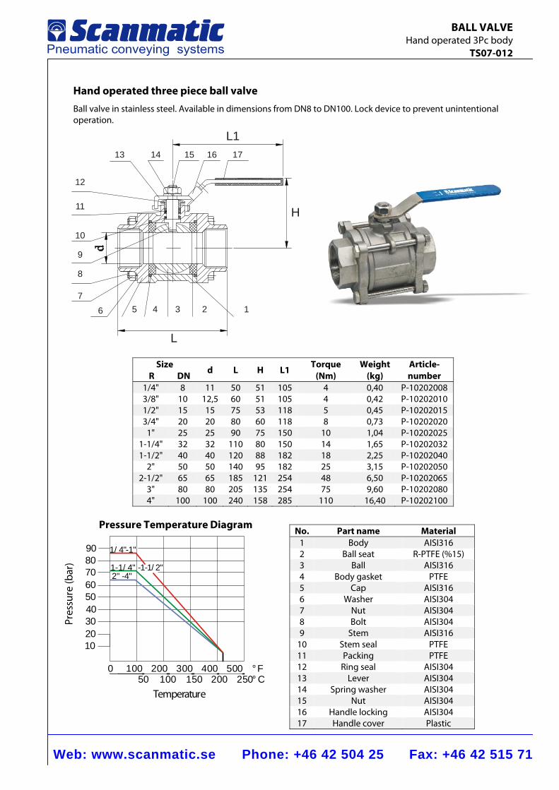
Web: www.scanmatic.se Phone: +46 42 504 25 Fax: +46 42 515 71
BALL VALVE Hand operated 3Pc body TS07-012
L1
H
L
16 57
8
9
10
11
12
13 14 15 16 17
4 3 2
Pressure Temperature Diagram
Temperature
0 100 200 300 400 50050 100 150 200 250
°F°C
908070605040302010
Pres
sure
(bar
) 1-1/4" -1-1/2"
1/4"-1"
2" -4"
Hand operated three piece ball valve Ball valve in stainless steel. Available in dimensions from DN8 to DN100. Lock device to prevent unintentional operation.
No. Part name Material 1 Body AISI316 2 Ball seat R-PTFE (%15)3 Ball AISI316 4 Body gasket PTFE 5 Cap AISI316 6 Washer AISI304 7 Nut AISI304 8 Bolt AISI304 9 Stem AISI316
10 Stem seal PTFE 11 Packing PTFE 12 Ring seal AISI304 13 Lever AISI304 14 Spring washer AISI304 15 Nut AISI304 16 Handle locking AISI304 17 Handle cover Plastic
Size R DN d L H L1 Torque
(Nm) Weight
(kg) Article- number
1/4" 8 11 50 51 105 4 0,40 P-10202008 3/8" 10 12,5 60 51 105 4 0,42 P-10202010 1/2" 15 15 75 53 118 5 0,45 P-10202015 3/4" 20 20 80 60 118 8 0,73 P-10202020
1" 25 25 90 75 150 10 1,04 P-10202025 1-1/4" 32 32 110 80 150 14 1,65 P-10202032 1-1/2" 40 40 120 88 182 18 2,25 P-10202040
2" 50 50 140 95 182 25 3,15 P-10202050 2-1/2" 65 65 185 121 254 48 6,50 P-10202065
3" 80 80 205 135 254 75 9,60 P-10202080 4" 100 100 240 158 285 110 16,40 P-10202100
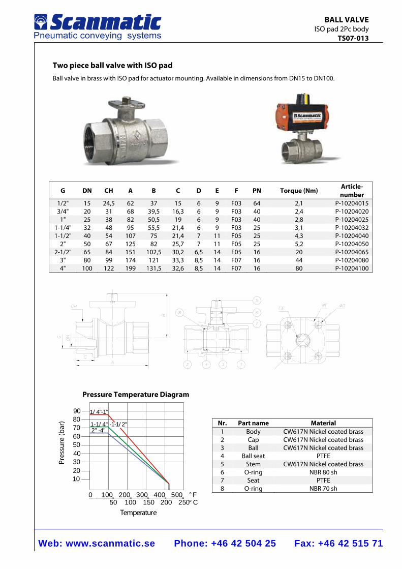
Web: www.scanmatic.se Phone: +46 42 504 25 Fax: +46 42 515 71
BALL VALVE ISO pad 2Pc body TS07-013
Pressure Temperature Diagram
Temperature
0 100 200 300 400 50050 100 150 200 250
°F°C
908070605040302010
Pres
sure
(bar
) 1-1/4" -1-1/2"
1/4"-1"
2" -4"
Two piece ball valve with ISO pad Ball valve in brass with ISO pad for actuator mounting. Available in dimensions from DN15 to DN100.
G DN CH A B C D E F PN Torque (Nm) Article-number
1/2" 15 24,5 62 37 15 6 9 F03 64 2,1 P-102040153/4" 20 31 68 39,5 16,3 6 9 F03 40 2,4 P-10204020
1" 25 38 82 50,5 19 6 9 F03 40 2,8 P-102040251-1/4" 32 48 95 55,5 21,4 6 9 F03 25 3,1 P-102040321-1/2" 40 54 107 75 21,4 7 11 F05 25 4,3 P-10204040
2" 50 67 125 82 25,7 7 11 F05 25 5,2 P-102040502-1/2" 65 84 151 102,5 30,2 6,5 14 F05 16 20 P-10204065
3" 80 99 174 121 33,3 8,5 14 F07 16 44 P-102040804" 100 122 199 131,5 32,6 8,5 14 F07 16 80 P-10204100
Nr. Part name Material1 Body CW617N Nickel coated brass2 Cap CW617N Nickel coated brass3 Ball CW617N Nickel coated brass4 Ball seat PTFE 5 Stem CW617N Nickel coated brass6 O-ring NBR 80 sh7 Seat PTFE 8 O-ring NBR 70 sh
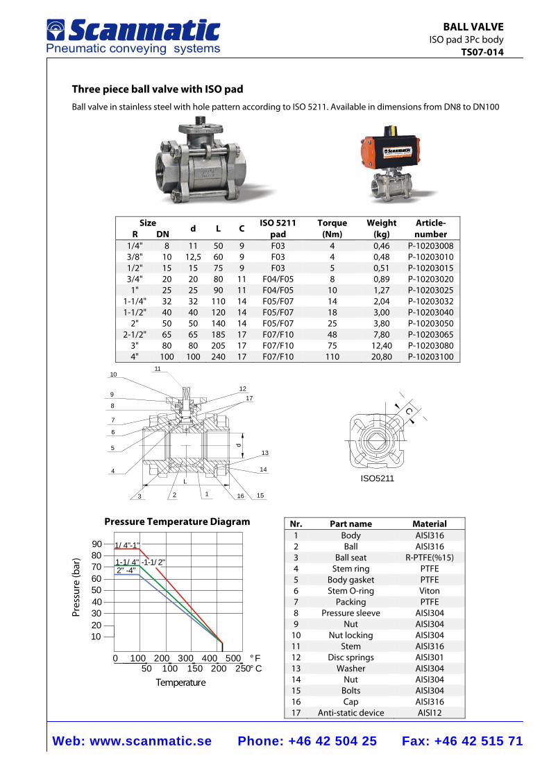
Web: www.scanmatic.se Phone: +46 42 504 25 Fax: +46 42 515 71
BALL VALVE ISO pad 3Pc body TS07-014
16123
4
5
7
11
9
8
12
6
15
14
13
10
d
L
17
ISO5211
C
Pressure Temperature Diagram
Temperature
0 100 200 300 400 50050 100 150 200 250
°F°C
908070605040302010
Pres
sure
(bar
) 1-1/4" -1-1/2"
1/4"-1"
2" -4"
Three piece ball valve with ISO pad Ball valve in stainless steel with hole pattern according to ISO 5211. Available in dimensions from DN8 to DN100
Size R DN d L C ISO 5211
pad Torque
(Nm) Weight
(kg) Article- number
1/4" 8 11 50 9 F03 4 0,46 P-10203008 3/8" 10 12,5 60 9 F03 4 0,48 P-10203010 1/2" 15 15 75 9 F03 5 0,51 P-10203015 3/4" 20 20 80 11 F04/F05 8 0,89 P-10203020
1" 25 25 90 11 F04/F05 10 1,27 P-10203025 1-1/4" 32 32 110 14 F05/F07 14 2,04 P-10203032 1-1/2" 40 40 120 14 F05/F07 18 3,00 P-10203040
2" 50 50 140 14 F05/F07 25 3,80 P-10203050 2-1/2" 65 65 185 17 F07/F10 48 7,80 P-10203065
3" 80 80 205 17 F07/F10 75 12,40 P-10203080 4" 100 100 240 17 F07/F10 110 20,80 P-10203100
Nr. Part name Material 1 Body AISI316 2 Ball AISI316 3 Ball seat R-PTFE(%15)4 Stem ring PTFE 5 Body gasket PTFE 6 Stem O-ring Viton 7 Packing PTFE 8 Pressure sleeve AISI304 9 Nut AISI304
10 Nut locking AISI304 11 Stem AISI316 12 Disc springs AISI301 13 Washer AISI304 14 Nut AISI304 15 Bolts AISI304 16 Cap AISI316 17 Anti-static device AISI12
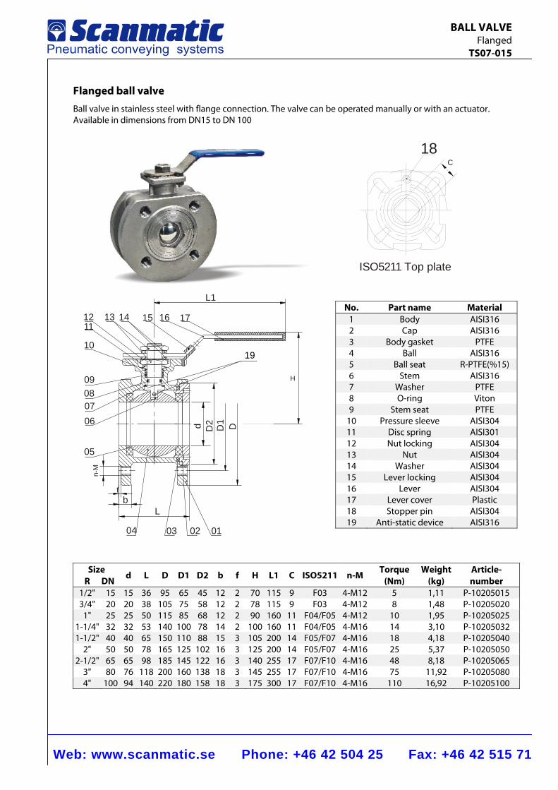
Web: www.scanmatic.se Phone: +46 42 504 25 Fax: +46 42 515 71
BALL VALVE Flanged TS07-015
010203
L
04
bf
05
n-M
d0607
D2 D1 D
0809
10
113121 15 171614
L1
H
19
Flanged ball valve Ball valve in stainless steel with flange connection. The valve can be operated manually or with an actuator. Available in dimensions from DN15 to DN 100
Size R DN d L D D1 D2 b f H L1 C ISO5211 n-M
Torque (Nm)
Weight (kg)
Article-number
1/2" 15 15 36 95 65 45 12 2 70 115 9 F03 4-M12 5 1,11 P-102050153/4" 20 20 38 105 75 58 12 2 78 115 9 F03 4-M12 8 1,48 P-10205020
1" 25 25 50 115 85 68 12 2 90 160 11 F04/F05 4-M12 10 1,95 P-102050251-1/4" 32 32 53 140 100 78 14 2 100 160 11 F04/F05 4-M16 14 3,10 P-102050321-1/2" 40 40 65 150 110 88 15 3 105 200 14 F05/F07 4-M16 18 4,18 P-10205040
2" 50 50 78 165 125 102 16 3 125 200 14 F05/F07 4-M16 25 5,37 P-102050502-1/2" 65 65 98 185 145 122 16 3 140 255 17 F07/F10 4-M16 48 8,18 P-10205065
3" 80 76 118 200 160 138 18 3 145 255 17 F07/F10 4-M16 75 11,92 P-102050804" 100 94 140 220 180 158 18 3 175 300 17 F07/F10 4-M16 110 16,92 P-10205100
No. Part name Material1 Body AISI3162 Cap AISI3163 Body gasket PTFE4 Ball AISI3165 Ball seat R-PTFE(%15)6 Stem AISI3167 Washer PTFE8 O-ring Viton9 Stem seat PTFE
10 Pressure sleeve AISI30411 Disc spring AISI30112 Nut locking AISI30413 Nut AISI30414 Washer AISI30415 Lever locking AISI30416 Lever AISI30417 Lever cover Plastic18 Stopper pin AISI30419 Anti-static device AISI316
1 8 C
ISO521 1 Top plate
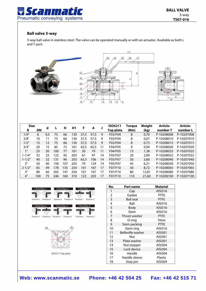
Web: www.scanmatic.se Phone: +46 42 504 25 Fax: +46 42 515 71
BALL VALVE 3-way TS07-016
AF
L1
1716151413
12
11
d
10
9
87
6 5 4L
3 2 1
h
H
L Port Plan 1 T Port Plan 1
T Port Plan 4T Port Plan 3T Port Plan 2
L Port Plan 2
Position-1 Position-2 Position-1 Position-2 Position-1 Position-2
Position-1 Position-2 Position-1 Position-2 Position-1 Position-2
18
ISO5211 Top plate
J
Ball valve 3-way 3-way ball valve in stainless steel. The valve can be operated manually or with an actuator. Available as both L and T-port.
Size R DN
d L H H1 F A J ISO5211Top plate
Torque(Nm)
Weight (kg)
Article-number T
Article-number L
1/4" 8 9,5 75 66 130 37,5 57,5 9 F03/F04 8 0,70 P-10208008 P-102070083/8" 10 11 75 66 130 37,5 57,5 9 F03/F04 8 0,67 P-10208010 P-102070101/2" 15 12 75 66 130 37,5 57,5 9 F03/F04 8 0,73 P-10208015 P-102070153/4" 20 15 85 72 161 42,5 65,5 11 F04/F05 9 0,94 P-10208020 P-10207020
1" 25 20 100 77 161 50 79 11 F04/F05 15 1,38 P-10208025 P-102070251-1/4" 32 25 122 92 203 61 97 14 F05/F07 20 2,89 P-10208032 P-102070321-1/2" 40 32 131 96 203 65,5 106 14 F05/F07 30 3,60 P-10208040 P-10207040
2" 50 40 158 107 203 79 129 14 F05/F07 45 6,21 P-10208050 P-102070502-1/2" 65 49 178 135 254 101 167 17 F07/F10 50 8,72 P-10208065 P-10207065
3" 80 60 202 147 254 101 167 17 F07/F10 80 12,81 P-10208080 P-102070804" 100 75 246 160 310 123 203 17 F07/F10 110 21,60 P-10208100 P-10207100
No. Part name Material 1 Cap AISI316 2 Gasket PTFE 3 Ball seat PTFE 4 Ball AISI316 5 Body AISI316 6 Stem AISI316 7 Thrust washer PTFE 8 O-ring Viton 9 Stem packing PTFE
10 Stem ring AISI316 11 Belleville washer AISI301 12 Nut AISI301 13 Plate washer AISI301 14 Nut stopper AISI304 15 Lock device AISI304 16 Handle AISI304 17 Handle sleeve Plastic 18 Stop pin AISI304
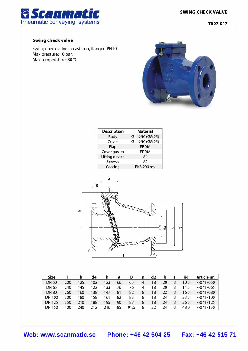
Web: www.scanmatic.se Phone: +46 42 504 25 Fax: +46 42 515 71
SWING CHECK VALVE TS07-017
A
B
h
fl b
DN
d4 k D
Swing check valve
Swing check valve in cast iron, flanged PN10. Max pressure: 10 bar. Max temperature: 80 °C
Description MaterialBody GJL-250 (GG 25)Cover GJL-250 (GG 25)Flap EPDM
Cover gasket EPDMLifting device A4
Screws A2Coating EKB 200 my
Size I k d4 h A B n d2 b f Kg Article nr.DN 50 200 125 102 123 66 65 4 18 20 3 10,5 P-0717050DN 65 240 145 122 133 76 76 4 18 20 3 14,5 P-0717065DN 80 260 160 138 147 81 82 8 18 22 3 16,5 P-0717080
DN 100 300 180 158 161 82 83 8 18 24 3 23,5 P-0717100DN 125 350 210 188 195 90 87 8 18 24 3 36,5 P-0717125DN 150 400 240 212 216 85 91,5 8 22 24 3 48,0 P-0717150
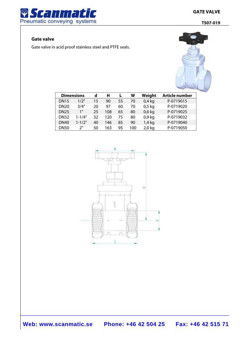
Web: www.scanmatic.se Phone: +46 42 504 25 Fax: +46 42 515 71
GATE VALVE TS07-019
Gate valve
Gate valve in acid proof stainless steel and PTFE seals.
Dimensions d H L W Weight Article number DN15 1/2" 15 90 55 70 0,4 kg P-0719015 DN20 3/4" 20 97 60 70 0,5 kg P-0719020 DN25 1" 25 108 65 80 0,6 kg P-0719025 DN32 1-1/4" 32 120 75 80 0,9 kg P-0719032 DN40 1-1/2" 40 146 85 90 1,4 kg P-0719040 DN50 2" 50 163 95 100 2,0 kg P-0719050
H
d
L
W
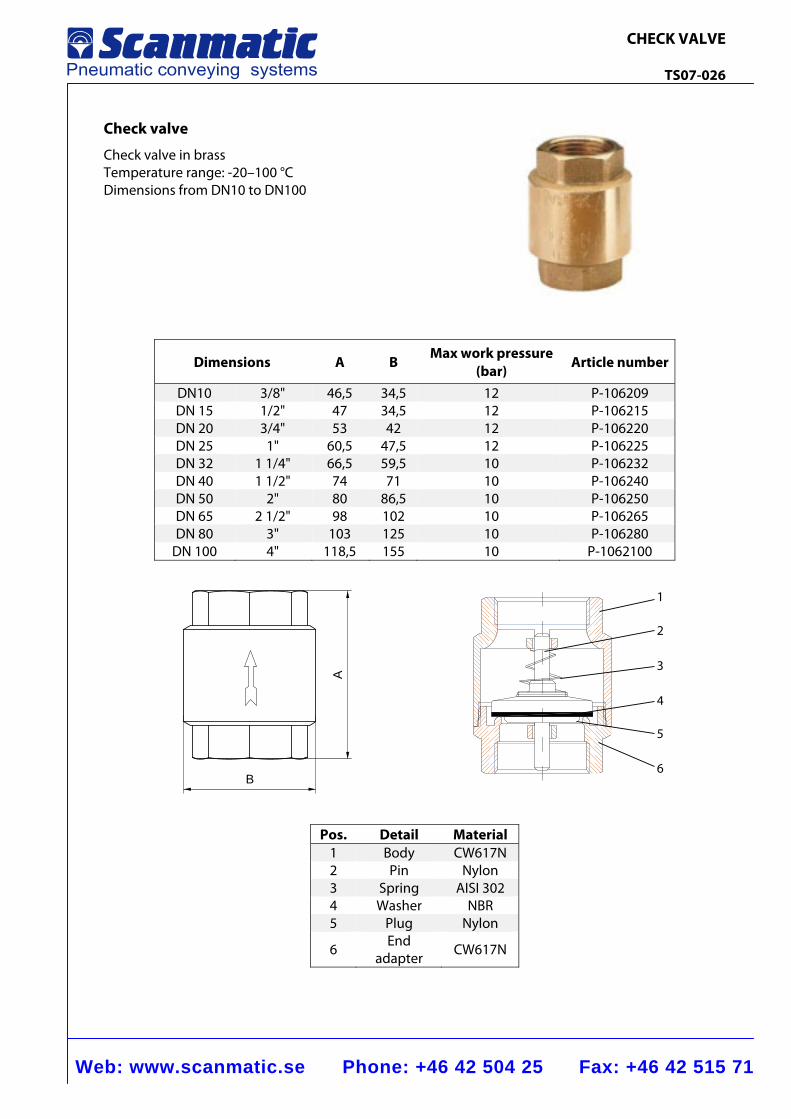
Web: www.scanmatic.se Phone: +46 42 504 25 Fax: +46 42 515 71
CHECK VALVE TS07-026
1
2
3
4
5
6B
A
Check valve
Check valve in brass Temperature range: -20–100 °C Dimensions from DN10 to DN100
Dimensions A B Max work pressure
(bar) Article number
DN10 3/8" 46,5 34,5 12 P-106209 DN 15 1/2" 47 34,5 12 P-106215 DN 20 3/4" 53 42 12 P-106220 DN 25 1" 60,5 47,5 12 P-106225 DN 32 1 1/4" 66,5 59,5 10 P-106232 DN 40 1 1/2" 74 71 10 P-106240 DN 50 2" 80 86,5 10 P-106250 DN 65 2 1/2" 98 102 10 P-106265 DN 80 3" 103 125 10 P-106280
DN 100 4" 118,5 155 10 P-1062100
Pos. Detail Material 1 Body CW617N 2 Pin Nylon 3 Spring AISI 302 4 Washer NBR 5 Plug Nylon
6 End adapter CW617N
MIXERS
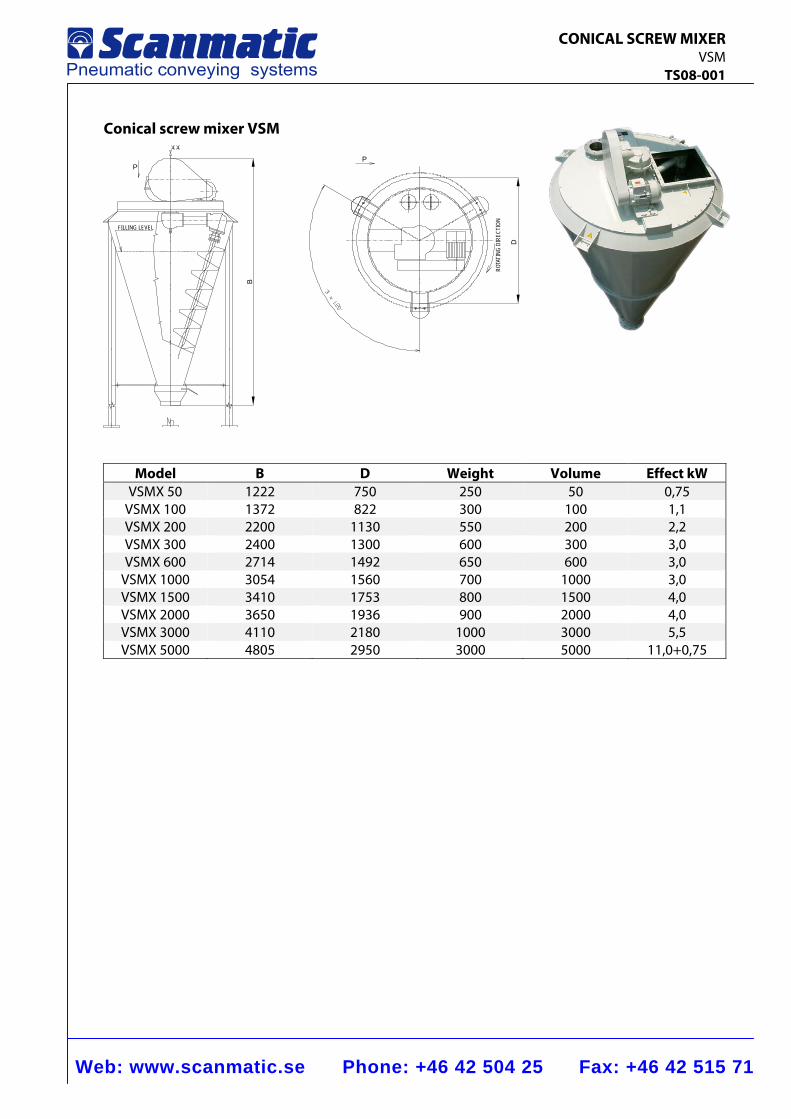
Web: www.scanmatic.se Phone: +46 42 504 25 Fax: +46 42 515 71
CONICAL SCREW MIXER VSM TS08-001
Conical screw mixer VSM
B
PP
FILLING LEVEL
ROTA
TING
DIR
ECTI
ON
D
Model B D Weight Volume Effect kW VSMX 50 1222 750 250 50 0,75
VSMX 100 1372 822 300 100 1,1 VSMX 200 2200 1130 550 200 2,2 VSMX 300 2400 1300 600 300 3,0 VSMX 600 2714 1492 650 600 3,0
VSMX 1000 3054 1560 700 1000 3,0 VSMX 1500 3410 1753 800 1500 4,0 VSMX 2000 3650 1936 900 2000 4,0 VSMX 3000 4110 2180 1000 3000 5,5 VSMX 5000 4805 2950 3000 5000 11,0+0,75
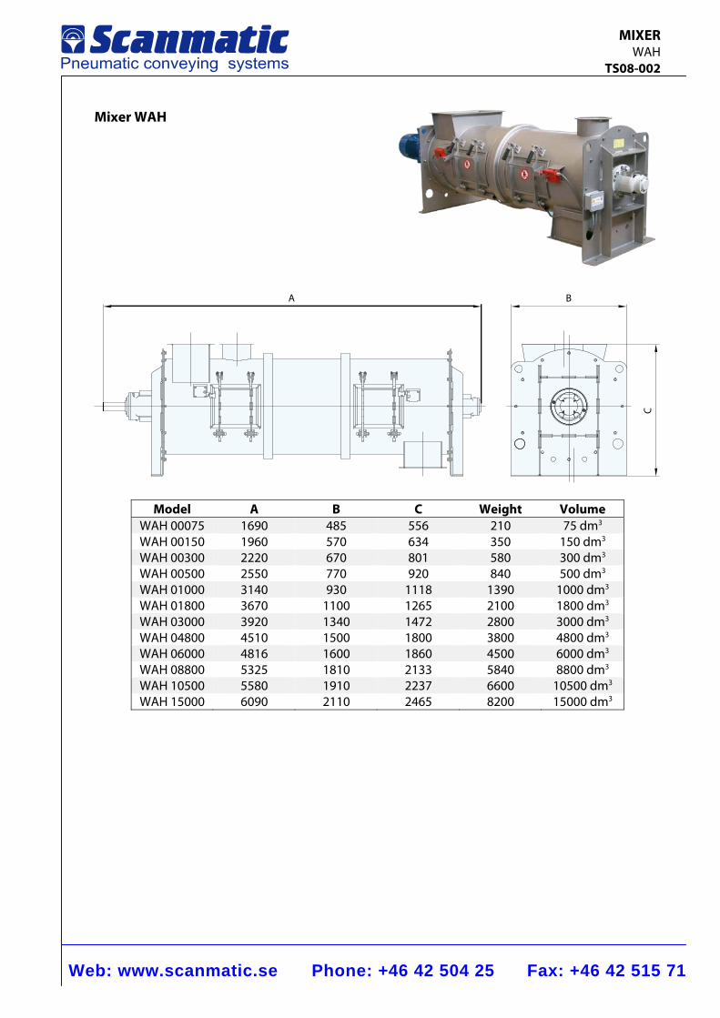
Web: www.scanmatic.se Phone: +46 42 504 25 Fax: +46 42 515 71
MIXER WAH TS08-002
Mixer WAH
A B
C
Model A B C Weight Volume WAH 00075 1690 485 556 210 75 dm3 WAH 00150 1960 570 634 350 150 dm3 WAH 00300 2220 670 801 580 300 dm3 WAH 00500 2550 770 920 840 500 dm3 WAH 01000 3140 930 1118 1390 1000 dm3 WAH 01800 3670 1100 1265 2100 1800 dm3 WAH 03000 3920 1340 1472 2800 3000 dm3 WAH 04800 4510 1500 1800 3800 4800 dm3 WAH 06000 4816 1600 1860 4500 6000 dm3 WAH 08800 5325 1810 2133 5840 8800 dm3 WAH 10500 5580 1910 2237 6600 10500 dm3 WAH 15000 6090 2110 2465 8200 15000 dm3
SIGNAL AND INDICATION
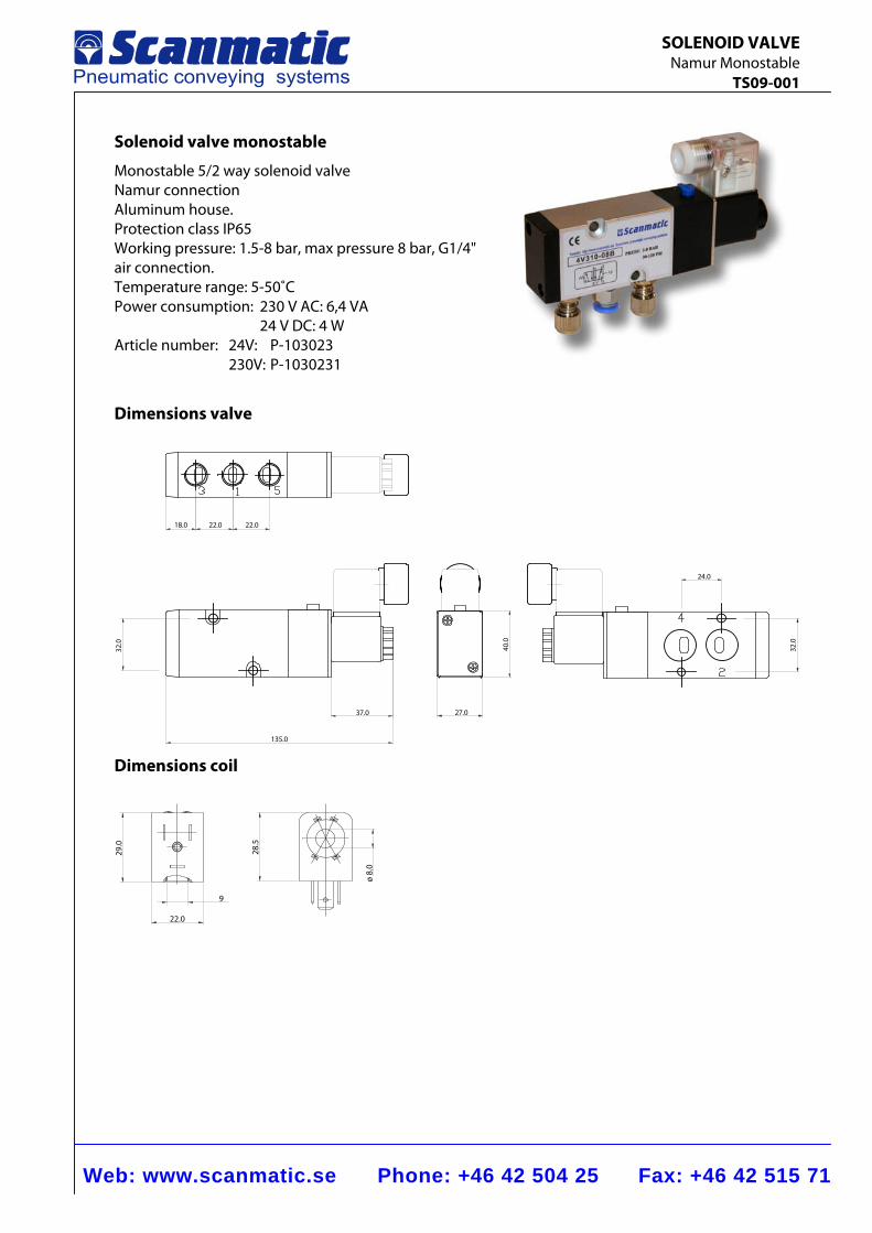
Web: www.scanmatic.se Phone: +46 42 504 25 Fax: +46 42 515 71
SOLENOID VALVE Namur Monostable TS09-001
Solenoid valve monostable
Monostable 5/2 way solenoid valve Namur connection Aluminum house. Protection class IP65 Working pressure: 1.5-8 bar, max pressure 8 bar, G1/4" air connection. Temperature range: 5-50˚C Power consumption: 230 V AC: 6,4 VA 24 V DC: 4 W Article number: 24V: P-103023 230V: P-1030231
Dimensions valve
18.0 22.0 22.0
32.0
135.0
37.0 27.0
40.0
24.0
32.0
Dimensions coil
29.0
22.0
9
28.5
ø 8.
0
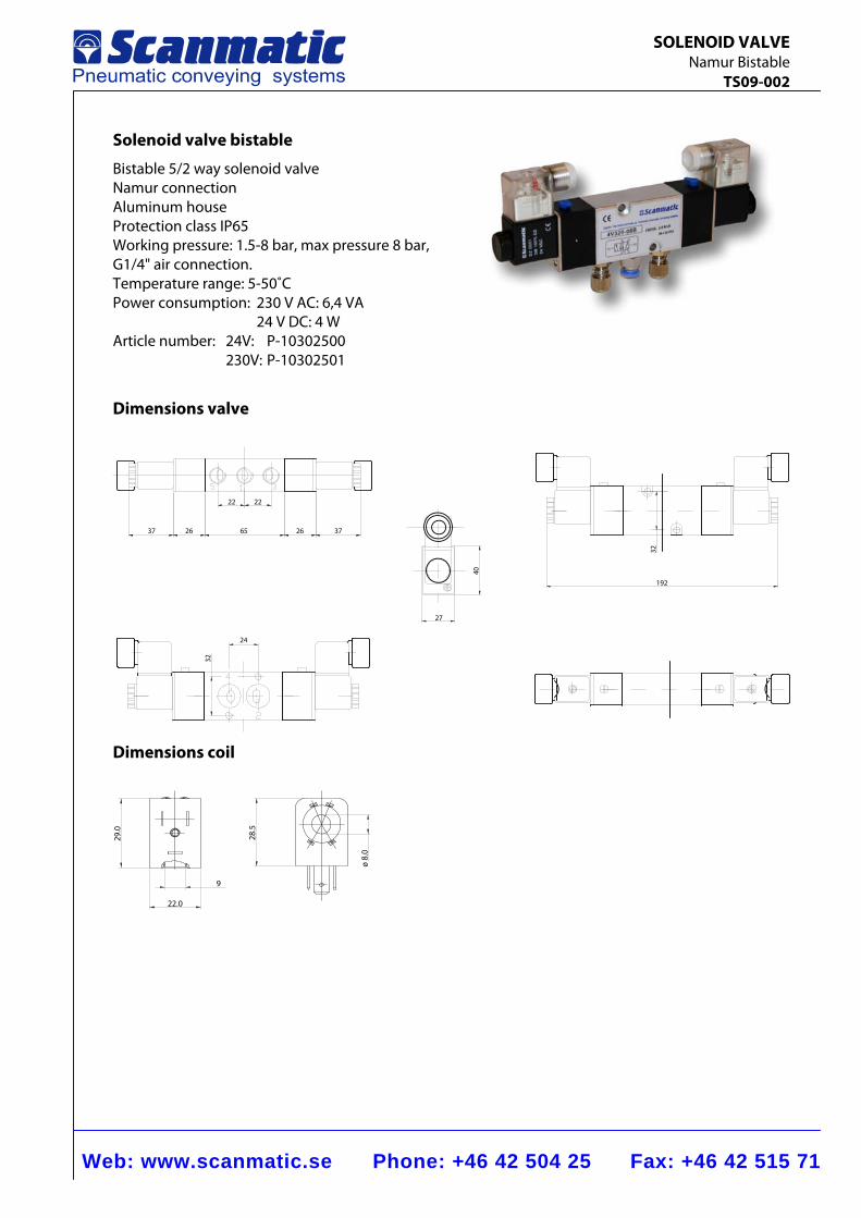
Web: www.scanmatic.se Phone: +46 42 504 25 Fax: +46 42 515 71
SOLENOID VALVE Namur Bistable TS09-002
Solenoid valve bistable
Bistable 5/2 way solenoid valve Namur connection Aluminum house Protection class IP65 Working pressure: 1.5-8 bar, max pressure 8 bar, G1/4" air connection. Temperature range: 5-50˚C Power consumption: 230 V AC: 6,4 VA 24 V DC: 4 W Article number: 24V: P-10302500 230V: P-10302501
Dimensions valve
37 26 26 3765
22 22
24
32
27
40
32
192
Dimensions coil
29.0
22.0
9
28.5
ø 8.
0
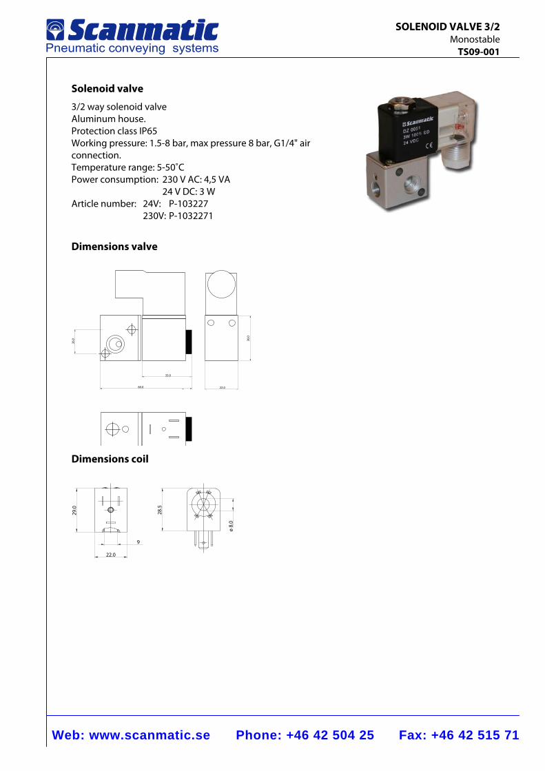
Web: www.scanmatic.se Phone: +46 42 504 25 Fax: +46 42 515 71
SOLENOID VALVE 3/2 Monostable TS09-001
Solenoid valve
3/2 way solenoid valve Aluminum house. Protection class IP65 Working pressure: 1.5-8 bar, max pressure 8 bar, G1/4" air connection. Temperature range: 5-50˚C Power consumption: 230 V AC: 4,5 VA 24 V DC: 3 W Article number: 24V: P-103227 230V: P-1032271
Dimensions valve
60.0
33.0
26.0
22.0
30,0
Dimensions coil
29.0
22.0
9
28.5
ø 8.
0
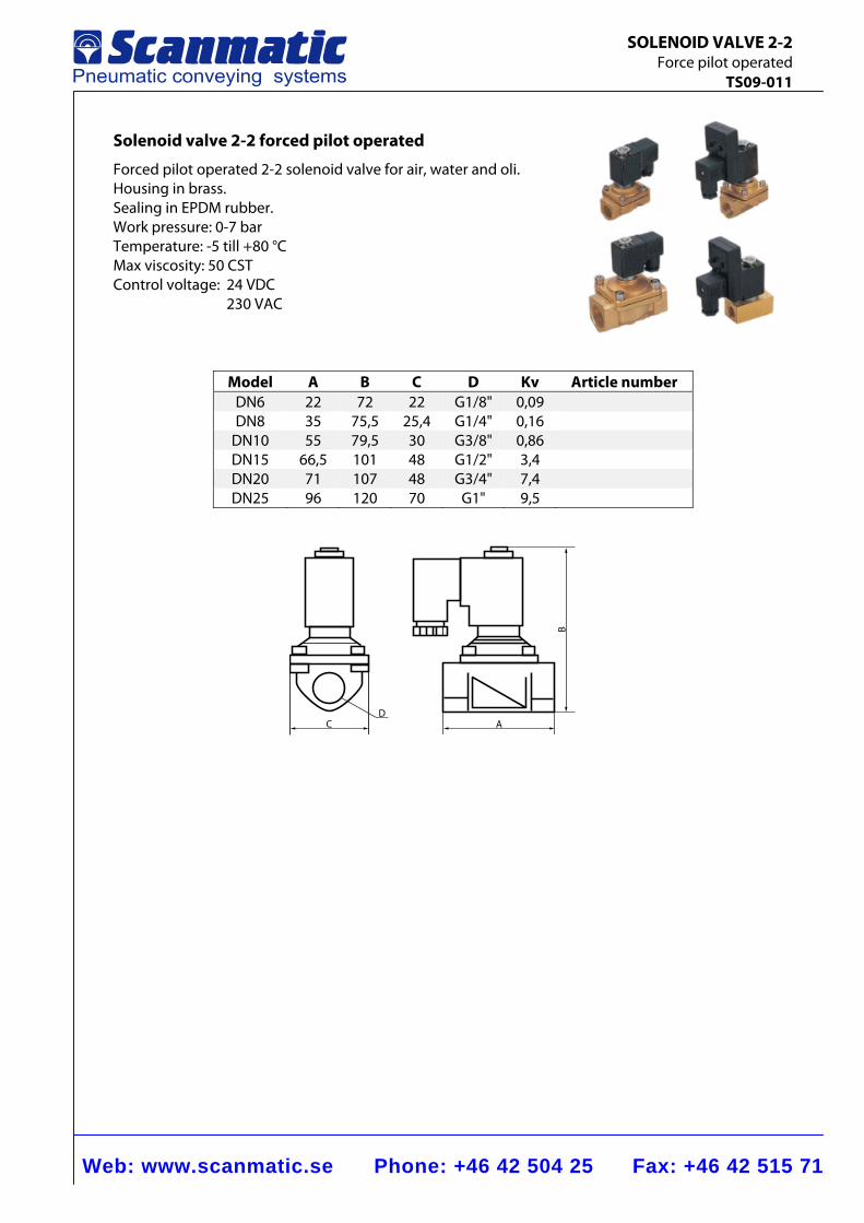
Web: www.scanmatic.se Phone: +46 42 504 25 Fax: +46 42 515 71
SOLENOID VALVE 2-2 Force pilot operated TS09-011
Solenoid valve 2-2 forced pilot operated
Forced pilot operated 2-2 solenoid valve for air, water and oli. Housing in brass. Sealing in EPDM rubber. Work pressure: 0-7 bar Temperature: -5 till +80 °C Max viscosity: 50 CST Control voltage: 24 VDC 230 VAC
Model A B C D Kv Article number DN6 22 72 22 G1/8" 0,09 DN8 35 75,5 25,4 G1/4" 0,16
DN10 55 79,5 30 G3/8" 0,86 DN15 66,5 101 48 G1/2" 3,4 DN20 71 107 48 G3/4" 7,4 DN25 96 120 70 G1" 9,5
C A
B
D
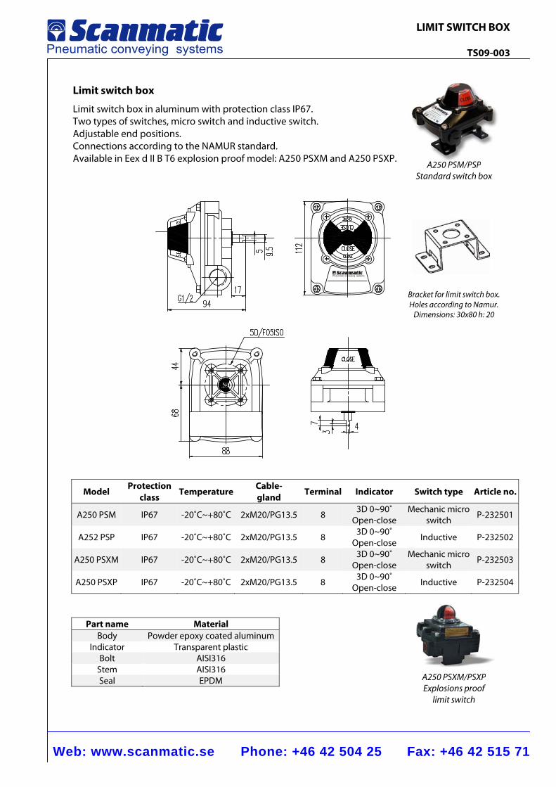
Web: www.scanmatic.se Phone: +46 42 504 25 Fax: +46 42 515 71
LIMIT SWITCH BOX TS09-003
Pneumatic conveying systems
Limit switch box
Limit switch box in aluminum with protection class IP67. Two types of switches, micro switch and inductive switch. Adjustable end positions. Connections according to the NAMUR standard. Available in Eex d II B T6 explosion proof model: A250 PSXM and A250 PSXP.
Model Protection
class TemperatureCable-gland Terminal Indicator Switch type Article no.
A250 PSM IP67 -20˚C~+80˚C 2xM20/PG13.5 8 3D 0~90˚Open-close
Mechanic microswitch P-232501
A252 PSP IP67 -20˚C~+80˚C 2xM20/PG13.5 8 3D 0~90˚
Open-close Inductive P-232502
A250 PSXM IP67 -20˚C~+80˚C 2xM20/PG13.5 8 3D 0~90˚Open-close
Mechanic micro switch P-232503
A250 PSXP IP67 -20˚C~+80˚C 2xM20/PG13.5 8 3D 0~90˚Open-close Inductive P-232504
Part name Material Body Powder epoxy coated aluminum
Indicator Transparent plasticBolt AISI316
Stem AISI316 Seal EPDM
A250 PSM/PSPStandard switch box
A250 PSXM/PSXPExplosions proof
limit switch
Bracket for limit switch box. Holes according to Namur.
Dimensions: 30x80 h: 20
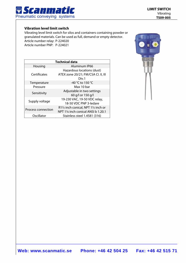
Web: www.scanmatic.se Phone: +46 42 504 25 Fax: +46 42 515 71
LIMIT SWITCH Vibrating TS09-005
Vibration level limit switch Vibrating level limit switch for silos and containers containing powder or granulated materials. Can be used as full, demand or empty detector. Article number relay: P-224020 Article number PNP: P-224021
Technical data Housing Aluminum IP66
Certificates Hazardous locations (dust)
ATEX zone 20/21; FM/CSA CI. II, III Div.1
Temperature -40 °C to 150 °C Pressure Max 10 bar
Sensitivity Adjustable in two settings
60 g/l or 150 g/l
Supply voltage 19-230 VAC, 19-50 VDC relay,
18-50 VDC PNP 3-ledare
Process connection R1½ inch conical, NPT 1½ inch or NPT 1¼ inch conical ANSI b 1.20.1
Oscillator Stainless steel 1.4581 (316)
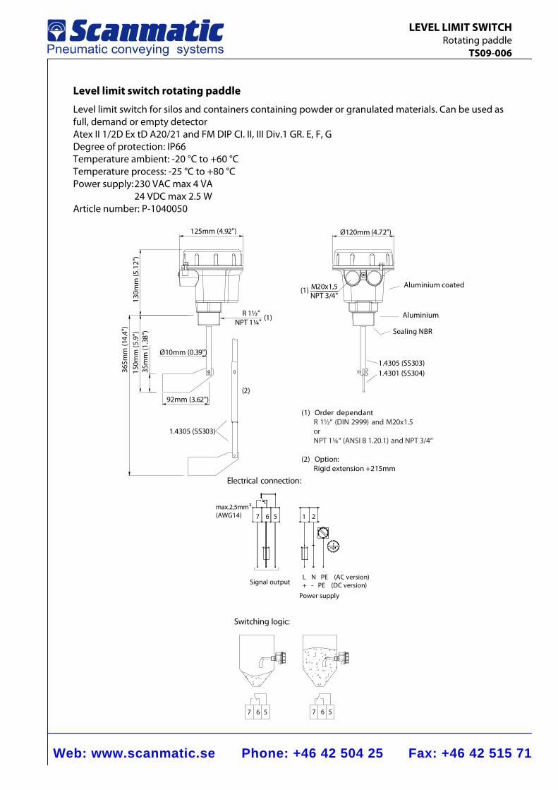
Web: www.scanmatic.se Phone: +46 42 504 25 Fax: +46 42 515 71
LEVEL LIMIT SWITCH Rotating paddle TS09-006
Level limit switch rotating paddle
Level limit switch for silos and containers containing powder or granulated materials. Can be used as full, demand or empty detector Atex II 1/2D Ex tD A20/21 and FM DIP CI. II, III Div.1 GR. E, F, G Degree of protection: IP66 Temperature ambient: -20 °C to +60 °C Temperature process: -25 °C to +80 °C Power supply: 230 VAC max 4 VA 24 VDC max 2.5 W Article number: P-1040050
(1)
150m
m (5
.9")
35m
m (1
.38"
)
365m
m (1
4.4"
)
1.4305 (SS303)
92mm (3.62")(2)
125mm (4.92")
Ø10mm (0.39")
130m
m(5
.12"
)
(1)
1.4301 (SS304)1.4305 (SS303)
M20x1,5NPT 3/4"
Ø120mm (4.72")
R 1½"NPT 1¼"
Aluminium
Aluminium coated
Sealing NBR
(1) Order dependantR 1½“ (DIN 2999) and M20x1.5orNPT 1¼“ (ANSI B 1.20.1) and NPT 3/4“
(2) Option:Rigid extension +215mm
max.2,5mm2(AWG14) 7 6 5
L N PE (AC version)+ - PE (DC version)
7 6 5
1 2
7 6 5
Electrical connection:
Signal output
Power supply
Switching logic:
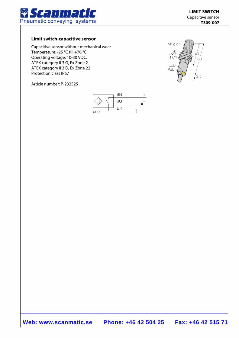
Web: www.scanmatic.se Phone: +46 42 504 25 Fax: +46 42 515 71
LIMIT SWITCH Capacitive sensor TS09-007
Limit switch-capacitive sensor
Capacitive sensor without mechanical wear.. Temperature: -25 °C till +70 °C. Operating voltage: 10-30 VDC. ATEX category II 3 G, Ex Zone 2 ATEX category II 3 D, Ex Zone 22 Protection class IP67 Article number: P-232525
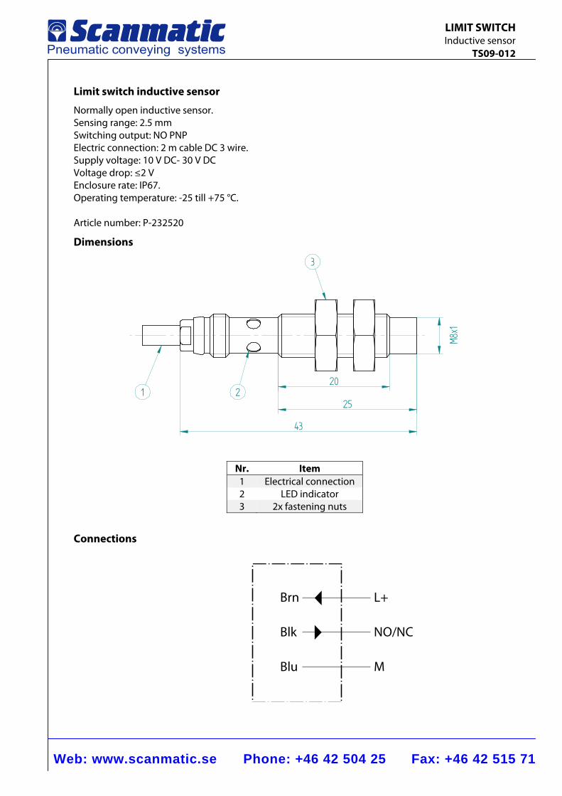
Web: www.scanmatic.se Phone: +46 42 504 25 Fax: +46 42 515 71
LIMIT SWITCH Inductive sensor TS09-012
Limit switch inductive sensor
Normally open inductive sensor. Sensing range: 2.5 mm Switching output: NO PNP Electric connection: 2 m cable DC 3 wire. Supply voltage: 10 V DC- 30 V DC Voltage drop: ≤2 V Enclosure rate: IP67. Operating temperature: -25 till +75 °C. Article number: P-232520
Dimensions
20
25
M8x1
43
1 2
3
Nr. Item 1 Electrical connection 2 LED indicator 3 2x fastening nuts
Connections
Brn L+
NO/NCBlk
MBlu
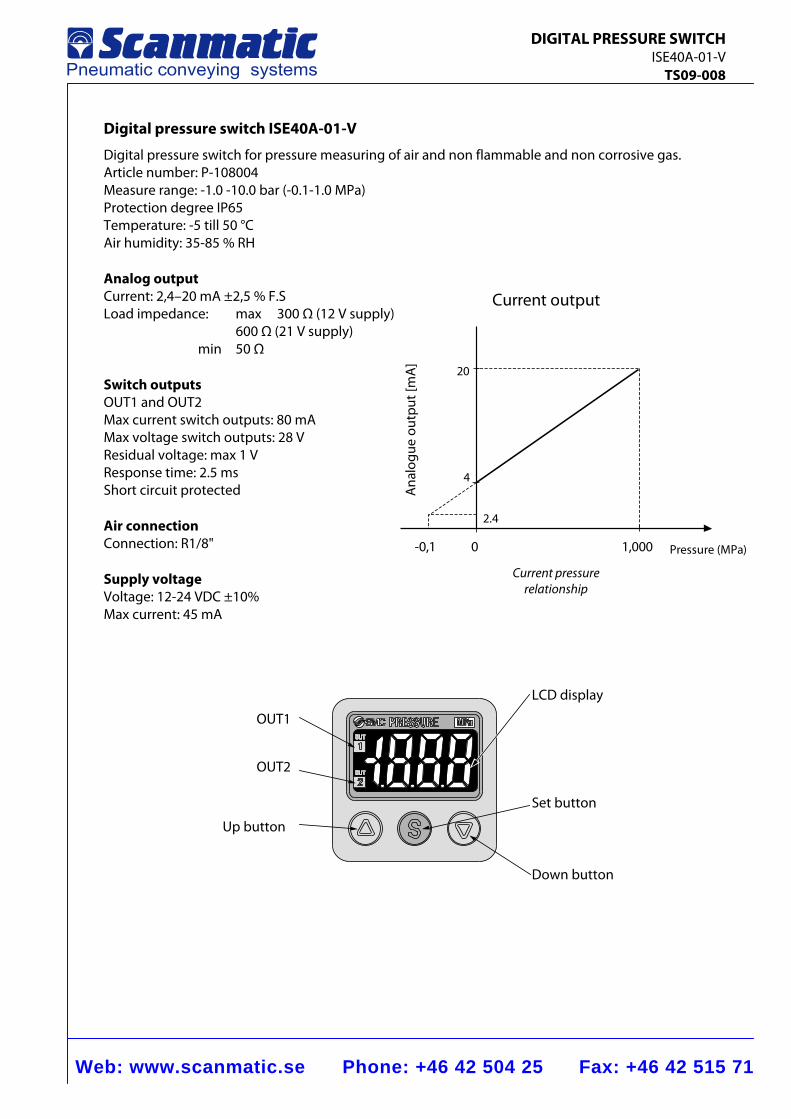
Web: www.scanmatic.se Phone: +46 42 504 25 Fax: +46 42 515 71
DIGITAL PRESSURE SWITCH ISE40A-01-V TS09-008
Current output
4
2.4
Pressure (MPa)
Ana
logu
eou
tput
[mA
]
20
0-0,1 1,000
Digital pressure switch ISE40A-01-V
Digital pressure switch for pressure measuring of air and non flammable and non corrosive gas. Article number: P-108004 Measure range: -1.0 -10.0 bar (-0.1-1.0 MPa) Protection degree IP65 Temperature: -5 till 50 °C Air humidity: 35-85 % RH Analog output Current: 2,4–20 mA ±2,5 % F.S Load impedance: max 300 Ω (12 V supply)
600 Ω (21 V supply) min 50 Ω
Switch outputs OUT1 and OUT2 Max current switch outputs: 80 mA Max voltage switch outputs: 28 V Residual voltage: max 1 V Response time: 2.5 ms Short circuit protected Air connection Connection: R1/8" Supply voltage Voltage: 12-24 VDC ±10% Max current: 45 mA
Current pressure relationship
OUT1
OUT2
Up button
Down button
Set button
LCD display
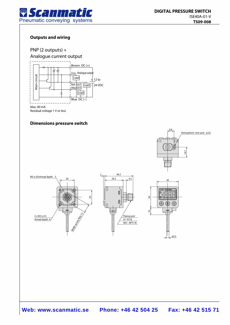
Web: www.scanmatic.se Phone: +46 42 504 25 Fax: +46 42 515 71
DIGITAL PRESSURE SWITCH ISE40A-01-V TS09-008
Outputs and wiring
12 to+
24 VDC–BlackWhite
Grey Analogue output
Load
Load
Load
Brown DC (+)
OUT1
Blue DC (–)
OUT2Mai
nci
rcui
t
PNP (2 outputs) +Analogue current output
Max. 80 mAResidual voltage 1 V or less
Dimensions pressure switch
3010
30
ø3.5
2 40.2
26.2 4.5
Piping port01 : R1/8N01 : NPT1/8
2 x M3 x 0.5thread depth 4
M5 x 0.8 thread depth 520
20
Wid
th ac
ross
flat
s 12
8.8Atmospheric vent port ø2.6
14.7
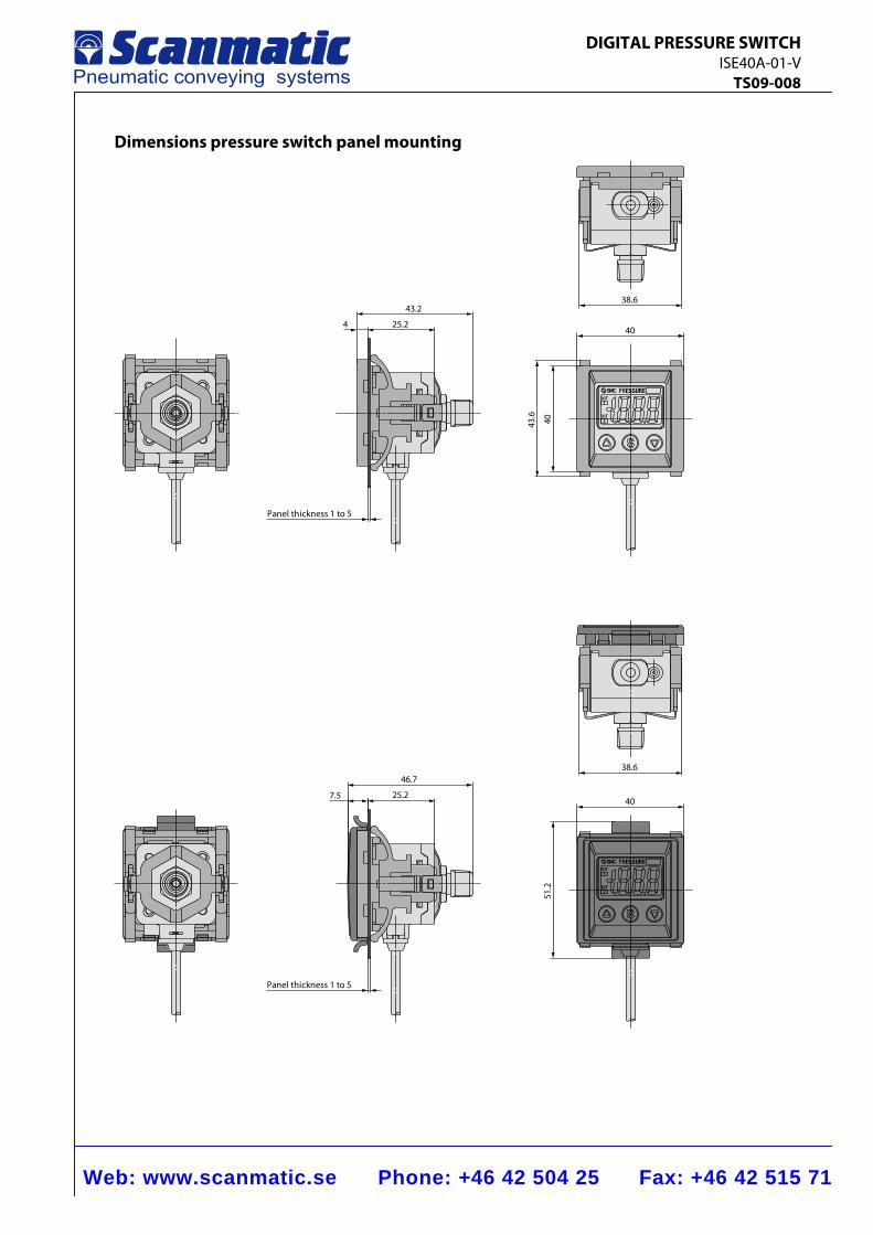
Web: www.scanmatic.se Phone: +46 42 504 25 Fax: +46 42 515 71
DIGITAL PRESSURE SWITCH ISE40A-01-V TS09-008
Dimensions pressure switch panel mounting
40
404 25.2
43.2
Panel thickness 1 to 5
38.6
40
51.2
7.5 25.2
46.7
Panel thickness 1 to 5
38.6
43.6
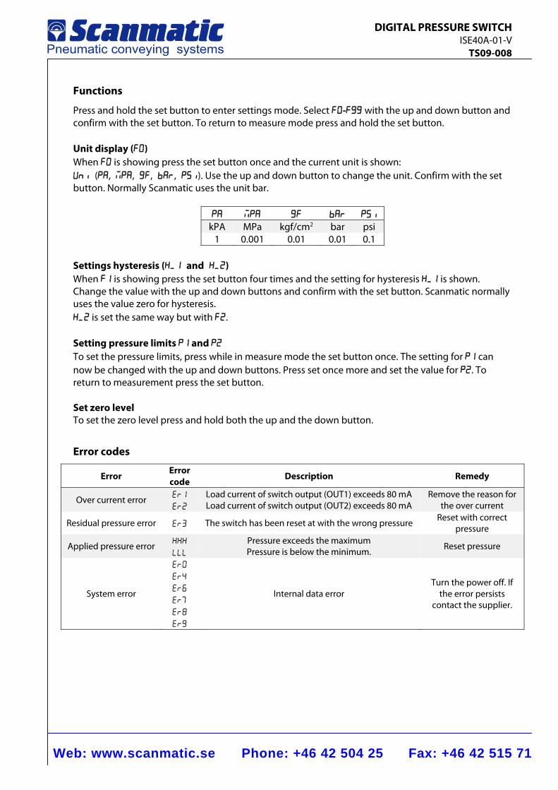
Web: www.scanmatic.se Phone: +46 42 504 25 Fax: +46 42 515 71
DIGITAL PRESSURE SWITCH ISE40A-01-V TS09-008
Functions
Press and hold the set button to enter settings mode. Select F0-F99 with the up and down button and confirm with the set button. To return to measure mode press and hold the set button. Unit display (F0) When f0 is showing press the set button once and the current unit is shown: uni (pa, MPA, gf, bar, psi). Use the up and down button to change the unit. Confirm with the set button. Normally Scanmatic uses the unit bar.
PA MPA Gf Bar psi
kPA MPa kgf/cm2 bar psi 1 0.001 0.01 0.01 0.1
Settings hysteresis (H_1 and H_2) When F1 is showing press the set button four times and the setting for hysteresis H_1 is shown. Change the value with the up and down buttons and confirm with the set button. Scanmatic normally uses the value zero for hysteresis. H_2 is set the same way but with F2. Setting pressure limits P1 and P2 To set the pressure limits, press while in measure mode the set button once. The setting for P1 can now be changed with the up and down buttons. Press set once more and set the value for P2. To return to measurement press the set button. Set zero level To set the zero level press and hold both the up and the down button.
Error codes
Error Error code Description Remedy
Over current error ER1
Er2
Load current of switch output (OUT1) exceeds 80 mA Load current of switch output (OUT2) exceeds 80 mA
Remove the reason for the over current
Residual pressure error Er3 The switch has been reset at with the wrong pressure Reset with correct pressure
Applied pressure error HHH
LLL
Pressure exceeds the maximum Pressure is below the minimum. Reset pressure
System error
er0
er4
er6
er7
er8
er9
Internal data error Turn the power off. If
the error persists contact the supplier.
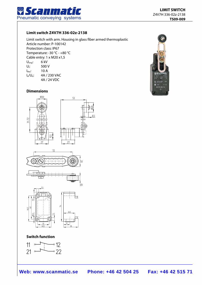
Web: www.scanmatic.se Phone: +46 42 504 25 Fax: +46 42 515 71
LIMIT SWITCH Z4V7H 336-02z-2138 TS09-009
Limit switch Z4V7H 336-02z-2138
Limit switch with arm. Housing in glass fiber armed thermoplastic Article number: P-100142 Protection class: IP67 Temperature: -30 °C - +80 °C Cable entry: 1 x M20 x1,5 Uimp: 6 kV Ui: 500 V Ithe: 10 A Ie/Ue: 4A / 230 VAC 4A / 24 VDC
Dimensions Ø20 53
27 27
8,5
31-72
Ø20
15,5
20
72
8,5
76
40,530
7,3
Ø5,3
6066,5
30,5
1738
9,5
5,3
Switch function
1121
1222
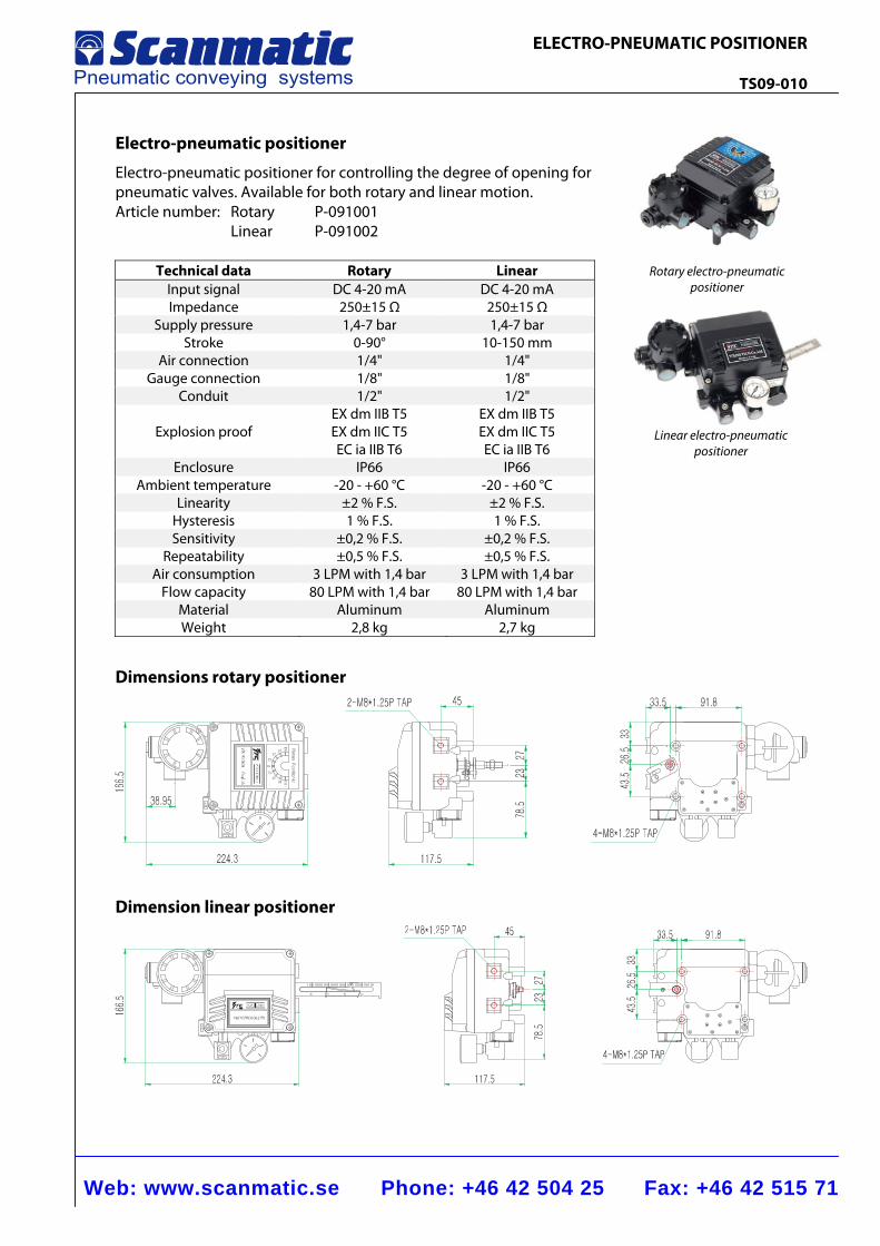
Web: www.scanmatic.se Phone: +46 42 504 25 Fax: +46 42 515 71
ELECTRO-PNEUMATIC POSITIONER TS09-010
Electro-pneumatic positioner
Electro-pneumatic positioner for controlling the degree of opening for pneumatic valves. Available for both rotary and linear motion. Article number: Rotary P-091001 Linear P-091002
Technical data Rotary LinearInput signal DC 4-20 mA DC 4-20 mAImpedance 250±15 Ω 250±15 Ω
Supply pressure 1,4-7 bar 1,4-7 barStroke 0-90° 10-150 mm
Air connection 1/4" 1/4"Gauge connection 1/8" 1/8"
Conduit 1/2" 1/2"
Explosion proof EX dm IIB T5EX dm IIC T5 EC ia IIB T6
EX dm IIB T5EX dm IIC T5 EC ia IIB T6
Enclosure IP66 IP66Ambient temperature -20 - +60 °C -20 - +60 °C
Linearity ±2 % F.S. ±2 % F.S.Hysteresis 1 % F.S. 1 % F.S.Sensitivity ±0,2 % F.S. ±0,2 % F.S.
Repeatability ±0,5 % F.S. ±0,5 % F.S.Air consumption 3 LPM with 1,4 bar 3 LPM with 1,4 bar
Flow capacity 80 LPM with 1,4 bar 80 LPM with 1,4 barMaterial Aluminum AluminumWeight 2,8 kg 2,7 kg
Dimensions rotary positioner
Dimension linear positioner
Rotary electro-pneumatic positioner
Linear electro-pneumatic positioner
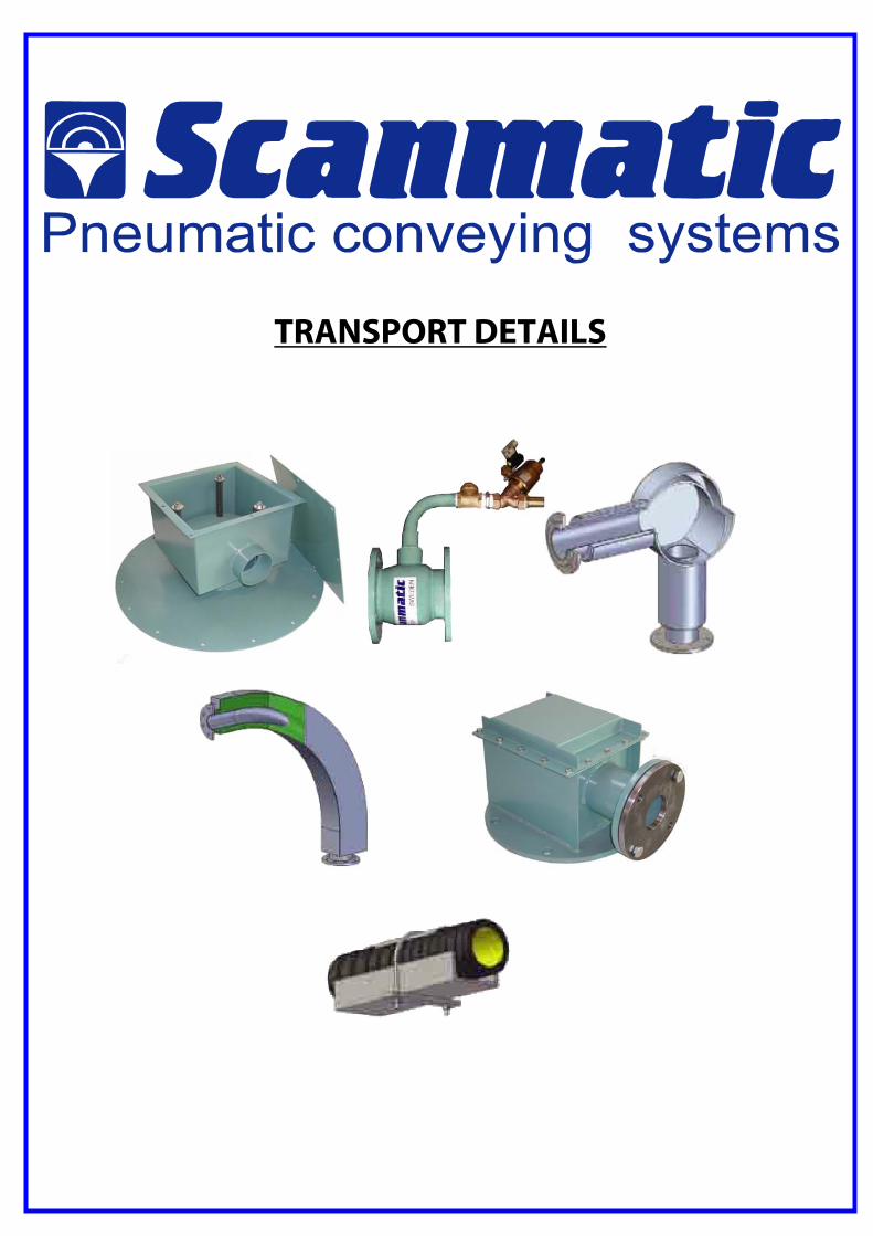
TRANSPORT DETAILS
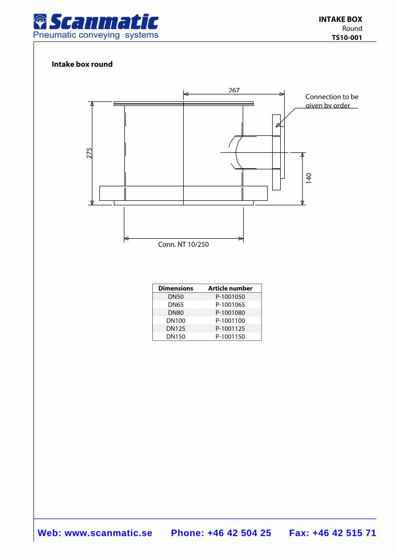
Web: www.scanmatic.se Phone: +46 42 504 25 Fax: +46 42 515 71
INTAKE BOX Round TS10-001
Intake box round
Dimensions Article numberDN50 P-1001050DN65 P-1001065DN80 P-1001080
DN100 P-1001100DN125 P-1001125DN150 P-1001150
Connection to be given by order
267
Conn. NT 10/250
275
140
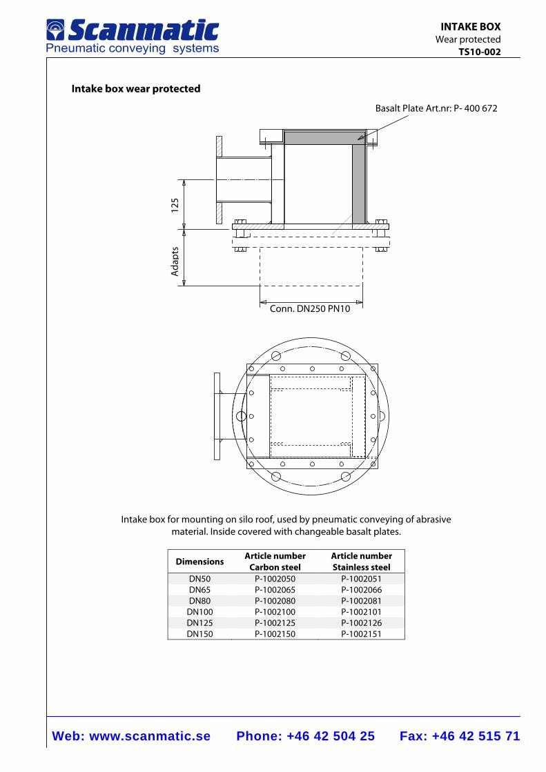
Web: www.scanmatic.se Phone: +46 42 504 25 Fax: +46 42 515 71
INTAKE BOX Wear protected TS10-002
Intake box wear protected
Intake box for mounting on silo roof, used by pneumatic conveying of abrasive material. Inside covered with changeable basalt plates.
Dimensions Article numberCarbon steel
Article number Stainless steel
DN50 P-1002050 P-1002051DN65 P-1002065 P-1002066DN80 P-1002080 P-1002081
DN100 P-1002100 P-1002101DN125 P-1002125 P-1002126DN150 P-1002150 P-1002151
Ada
pts
125
Conn. DN250 PN10
Basalt Plate Art.nr: P- 400 672
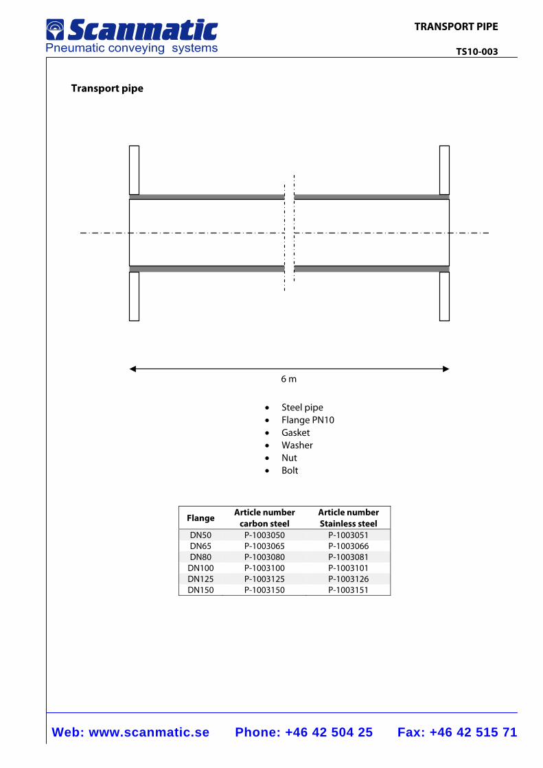
Web: www.scanmatic.se Phone: +46 42 504 25 Fax: +46 42 515 71
TRANSPORT PIPE TS10-003
Transport pipe
Flange Article number
carbon steel Article numberStainless steel
DN50 P-1003050 P-1003051DN65 P-1003065 P-1003066DN80 P-1003080 P-1003081
DN100 P-1003100 P-1003101DN125 P-1003125 P-1003126DN150 P-1003150 P-1003151
6 m
• Steel pipe • Flange PN10 • Gasket • Washer • Nut • Bolt
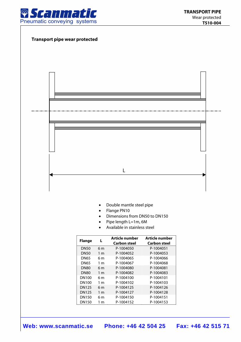
Web: www.scanmatic.se Phone: +46 42 504 25 Fax: +46 42 515 71
TRANSPORT PIPE Wear protected TS10-004
Transport pipe wear protected
L
• Double mantle steel pipe • Flange PN10 • Dimensions from DN50 to DN150 • Pipe length L=1m, 6M • Available in stainless steel
Flange L Article numberCarbon steel
Article number Carbon steel
DN50 DN50
6 m1 m
P-1004050P-1004052
P-1004051P-1004053
DN65 DN65
6 m1 m
P-1004065P-1004067
P-1004066P-1004068
DN80 DN80
6 m1 m
P-1004080P-1004082
P-1004081P-1004083
DN100 DN100
6 m1 m
P-1004100P-1004102
P-1004101P-1004103
DN125 DN125
6 m1 m
P-1004125P-1004127
P-1004126P-1004128
DN150 DN150
6 m1 m
P-1004150P-1004152
P-1004151P-1004153
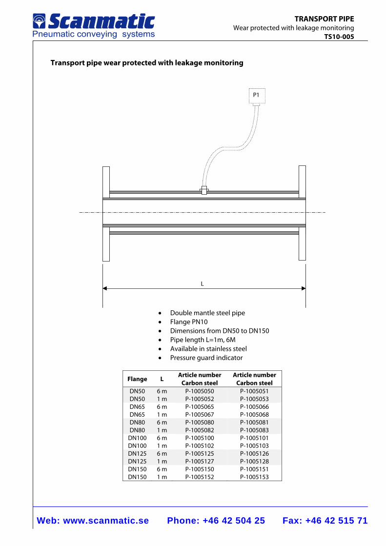
Web: www.scanmatic.se Phone: +46 42 504 25 Fax: +46 42 515 71
TRANSPORT PIPE Wear protected with leakage monitoring TS10-005
Transport pipe wear protected with leakage monitoring
P1
L
• Double mantle steel pipe • Flange PN10 • Dimensions from DN50 to DN150 • Pipe length L=1m, 6M • Available in stainless steel • Pressure guard indicator
Flange L Article numberCarbon steel
Article number Carbon steel
DN50 DN50
6 m1 m
P-1005050P-1005052
P-1005051P-1005053
DN65 DN65
6 m1 m
P-1005065P-1005067
P-1005066P-1005068
DN80 DN80
6 m1 m
P-1005080P-1005082
P-1005081P-1005083
DN100 DN100
6 m1 m
P-1005100P-1005102
P-1005101P-1005103
DN125 DN125
6 m1 m
P-1005125P-1005127
P-1005126P-1005128
DN150 DN150
6 m1 m
P-1005150P-1005152
P-1005151P-1005153
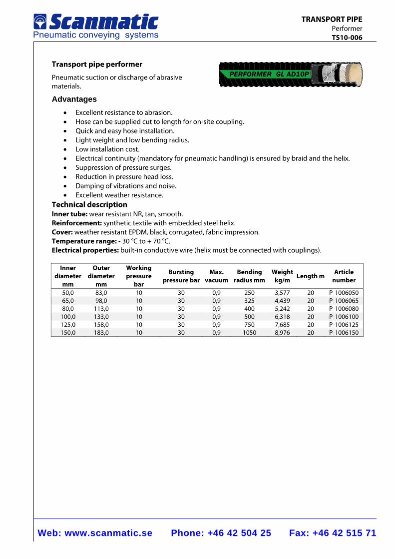
Web: www.scanmatic.se Phone: +46 42 504 25 Fax: +46 42 515 71
TRANSPORT PIPE Performer TS10-006
Transport pipe performer
Pneumatic suction or discharge of abrasive materials.
Advantages • Excellent resistance to abrasion. • Hose can be supplied cut to length for on-site coupling. • Quick and easy hose installation. • Light weight and low bending radius. • Low installation cost. • Electrical continuity (mandatory for pneumatic handling) is ensured by braid and the helix. • Suppression of pressure surges. • Reduction in pressure head loss. • Damping of vibrations and noise. • Excellent weather resistance.
Technical description Inner tube: wear resistant NR, tan, smooth. Reinforcement: synthetic textile with embedded steel helix. Cover: weather resistant EPDM, black, corrugated, fabric impression. Temperature range: - 30 °C to + 70 °C. Electrical properties: built-in conductive wire (helix must be connected with couplings).
Inner diameter
mm
Outer diameter
mm
Working pressure
bar
Bursting pressure bar
Max. vacuum
Bending radius mm
Weight kg/m Length m Article
number
50,0 83,0 10 30 0,9 250 3,577 20 P-100605065,0 98,0 10 30 0,9 325 4,439 20 P-100606580,0 113,0 10 30 0,9 400 5,242 20 P-1006080
100,0 133,0 10 30 0,9 500 6,318 20 P-1006100125,0 158,0 10 30 0,9 750 7,685 20 P-1006125150,0 183,0 10 30 0,9 1050 8,976 20 P-1006150
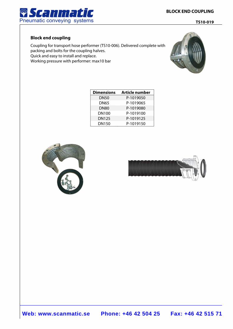
Web: www.scanmatic.se Phone: +46 42 504 25 Fax: +46 42 515 71
BLOCK END COUPLING TS10-019
Block end coupling
Coupling for transport hose performer (TS10-006). Delivered complete with packing and bolts for the coupling halves. Quick and easy to install and replace. Working pressure with performer: max10 bar
Dimensions Article number DN50 P-1019050 DN65 P-1019065 DN80 P-1019080
DN100 P-1019100 DN125 P-1019125 DN150 P-1019150
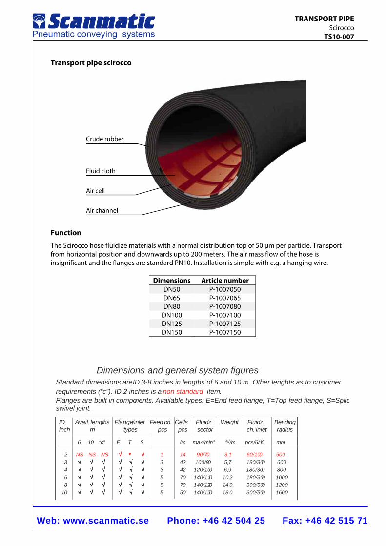
Web: www.scanmatic.se Phone: +46 42 504 25 Fax: +46 42 515 71
TRANSPORT PIPE Scirocco TS10-007
Transport pipe scirocco
Crude rubber
Fluid cloth
Air channel
Air cell
Function
The Scirocco hose fluidize materials with a normal distribution top of 50 μm per particle. Transport from horizontal position and downwards up to 200 meters. The air mass flow of the hose is insignificant and the flanges are standard PN10. Installation is simple with e.g. a hanging wire.
Dimensions Article number DN50 P-1007050 DN65 P-1007065 DN80 P-1007080
DN100 P-1007100 DN125 P-1007125 DN150 P-1007150
Dimensions and general system figuresStandard dimensions areID 3-8 inches in lengths of 6 and 10 m. Other lenghts as to customerrequirements (“c”). ID 2 inches is a non standard item.Flanges are built in components. Available types: E=End feed flange, T=Top feed flange, S=Splicswivel joint.
ID Avail. lengths Flange/inlet Feed ch. Cells Fluidz. Weight Fluidz. BendingInch m types pcs pcs sector ch. inlet radius
6 10 “c” E T S /m max/min° kg/m pcs/6/10 mm
2 NS NS NS √√√√√ • √√√√√ 1 14 90/70 3,1 60/100 5003 √√√√√ √√√√√ √√√√√ √√√√√ √√√√√ √√√√√ 3 42 100/90 5,7 180/300 6004 √√√√√ √√√√√ √√√√√ √√√√√ √√√√√ √√√√√ 3 42 120/100 6,9 180/300 8006 √√√√√ √√√√√ √√√√√ √√√√√ √√√√√ √√√√√ 5 70 140/110 10,2 180/300 10008 √√√√√ √√√√√ √√√√√ √√√√√ √√√√√ √√√√√ 5 70 140/120 14,0 300/500 1200
10 √√√√√ √√√√√ √√√√√ √√√√√ √√√√√ √√√√√ 5 50 140/120 18,0 300/500 1600
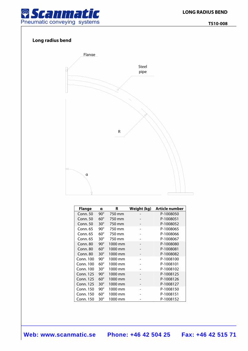
Web: www.scanmatic.se Phone: +46 42 504 25 Fax: +46 42 515 71
LONG RADIUS BEND TS10-008
Long radius bend
Flange α R Weight (kg) Article number Conn. 50 Conn. 50 Conn. 50
90°60° 30°
750 mm750 mm 750 mm
-- -
P-1008050 P-1008051 P-1008052
Conn. 65 Conn. 65 Conn. 65
90°60° 30°
750 mm750 mm 750 mm
-- -
P-1008065 P-1008066 P-1008067
Conn. 80 Conn. 80 Conn. 80
90°60° 30°
1000 mm1000 mm 1000 mm
-- -
P-1008080 P-1008081 P-1008082
Conn. 100 Conn. 100 Conn. 100
90°60° 30°
1000 mm1000 mm 1000 mm
-- -
P-1008100 P-1008101 P-1008102
Conn. 125 Conn. 125 Conn. 125
90°60° 30°
1000 mm1000 mm 1000 mm
-- -
P-1008125 P-1008126 P-1008127
Conn. 150 Conn. 150 Conn. 150
90°60° 30°
1000 mm1000 mm 1000 mm
-- -
P-1008150 P-1008151 P-1008152
R
α
Steel pipe
Flange
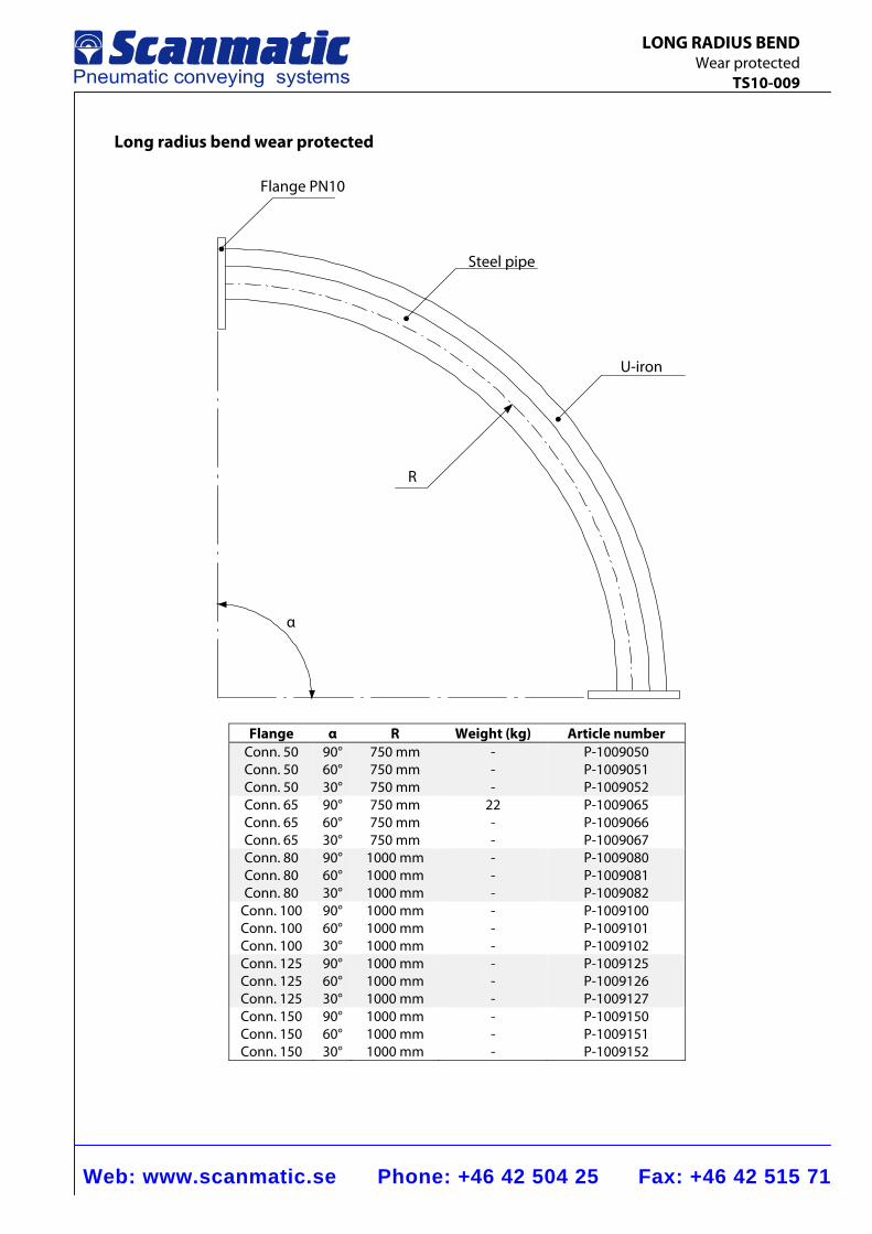
Web: www.scanmatic.se Phone: +46 42 504 25 Fax: +46 42 515 71
LONG RADIUS BEND Wear protected TS10-009
Long radius bend wear protected
Flange α R Weight (kg) Article number Conn. 50 Conn. 50 Conn. 50
90° 60° 30°
750 mm750 mm 750 mm
-- -
P-1009050 P-1009051 P-1009052
Conn. 65 Conn. 65 Conn. 65
90° 60° 30°
750 mm750 mm 750 mm
22- -
P-1009065 P-1009066 P-1009067
Conn. 80 Conn. 80 Conn. 80
90° 60° 30°
1000 mm1000 mm 1000 mm
-- -
P-1009080 P-1009081 P-1009082
Conn. 100 Conn. 100 Conn. 100
90° 60° 30°
1000 mm1000 mm 1000 mm
-- -
P-1009100 P-1009101 P-1009102
Conn. 125 Conn. 125 Conn. 125
90° 60° 30°
1000 mm1000 mm 1000 mm
-- -
P-1009125 P-1009126 P-1009127
Conn. 150 Conn. 150 Conn. 150
90° 60° 30°
1000 mm1000 mm 1000 mm
-- -
P-1009150 P-1009151 P-1009152
Flange PN10
U-iron
Steel pipe
R
α
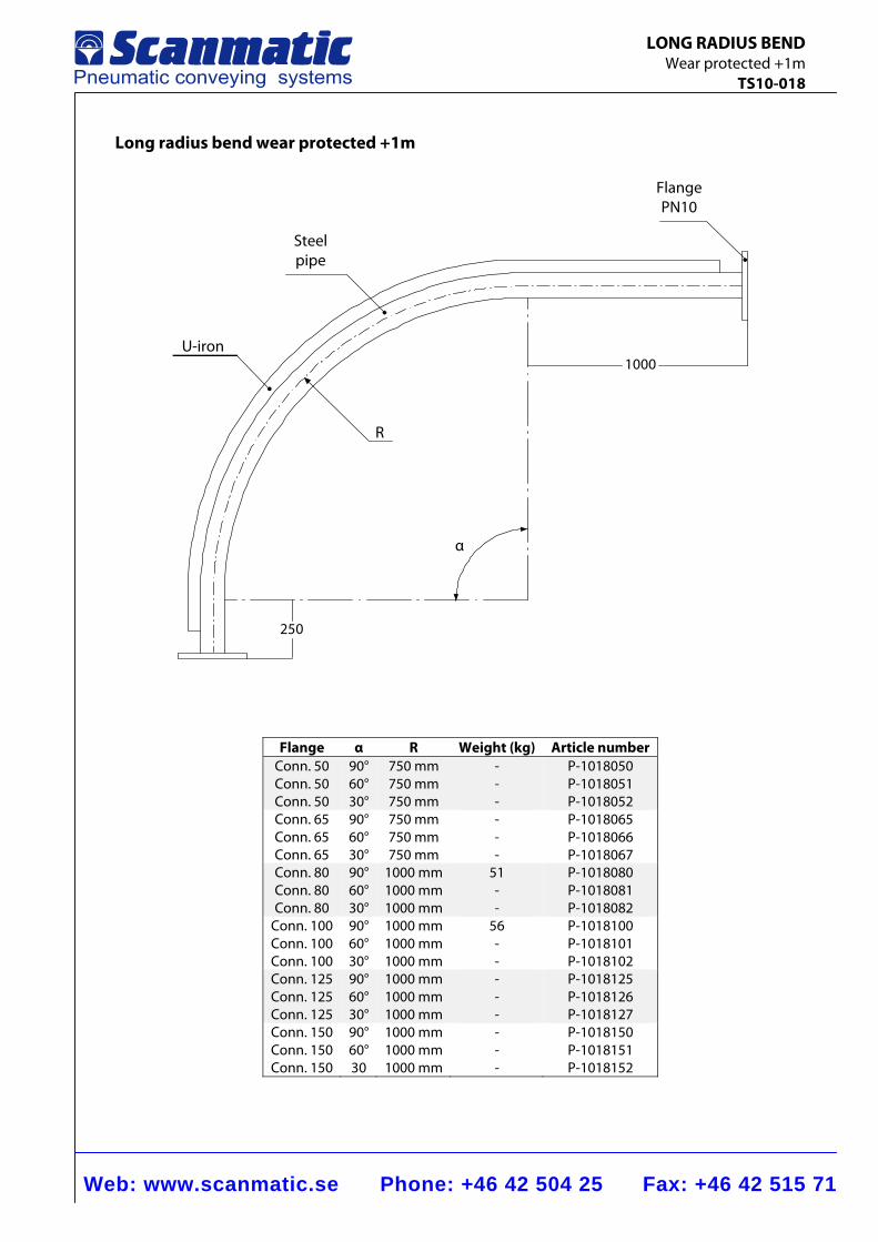
Web: www.scanmatic.se Phone: +46 42 504 25 Fax: +46 42 515 71
LONG RADIUS BEND Wear protected +1m TS10-018
Long radius bend wear protected +1m
250
1000
Flange α R Weight (kg) Article number Conn. 50 Conn. 50 Conn. 50
90°60° 30°
750 mm750 mm 750 mm
-- -
P-1018050 P-1018051 P-1018052
Conn. 65 Conn. 65 Conn. 65
90°60° 30°
750 mm750 mm 750 mm
-- -
P-1018065 P-1018066 P-1018067
Conn. 80 Conn. 80 Conn. 80
90°60° 30°
1000 mm1000 mm 1000 mm
51- -
P-1018080 P-1018081 P-1018082
Conn. 100 Conn. 100 Conn. 100
90°60° 30°
1000 mm1000 mm 1000 mm
56- -
P-1018100 P-1018101 P-1018102
Conn. 125 Conn. 125 Conn. 125
90°60° 30°
1000 mm1000 mm 1000 mm
-- -
P-1018125 P-1018126 P-1018127
Conn. 150 Conn. 150 Conn. 150
90°60° 30
1000 mm1000 mm 1000 mm
-- -
P-1018150 P-1018151 P-1018152
Flange PN10
U-iron
Steel pipe
R
α
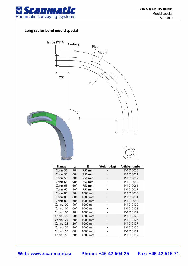
Web: www.scanmatic.se Phone: +46 42 504 25 Fax: +46 42 515 71
LONG RADIUS BEND Mould special TS10-010
Long radius bend mould special
Flange α R Weight (kg) Article number
Conn. 50 Conn. 50 Conn. 50
90° 60° 30°
750 mm750 mm 750 mm
-- -
P-1010050 P-1010051 P-1010052
Conn. 65 Conn. 65 Conn. 65
90° 60° 30°
750 mm750 mm 750 mm
-- -
P-1010065 P-1010066 P-1010067
Conn. 80 Conn. 80 Conn. 80
90° 60° 30°
1000 mm1000 mm 1000 mm
-- -
P-1010080 P-1010081 P-1010082
Conn. 100 Conn. 100 Conn. 100
90° 60° 30°
1000 mm1000 mm 1000 mm
-- -
P-1010100 P-1010101 P-1010102
Conn. 125 Conn. 125 Conn. 125
90° 60° 30°
1000 mm1000 mm 1000 mm
-- -
P-1010125 P-1010126 P-1010127
Conn. 150 Conn. 150 Conn. 150
90° 60° 30°
1000 mm1000 mm 1000 mm
-- -
P-1010150 P-1010151 P-1010152
R
Mould
PipeCasting Flange PN10
250
α
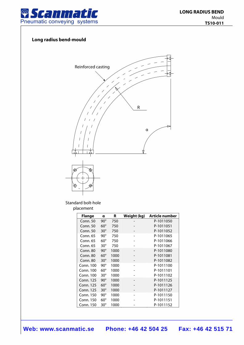
Web: www.scanmatic.se Phone: +46 42 504 25 Fax: +46 42 515 71
LONG RADIUS BEND Mould TS10-011
Long radius bend-mould
Flange α R Weight (kg) Article number Conn. 50 Conn. 50 Conn. 50
90°60° 30°
750750 750
-- -
P-1011050P-1011051 P-1011052
Conn. 65 Conn. 65 Conn. 65
90°60° 30°
750750 750
-- -
P-1011065P-1011066 P-1011067
Conn. 80 Conn. 80 Conn. 80
90°60° 30°
10001000 1000
-- -
P-1011080P-1011081 P-1011082
Conn. 100 Conn. 100 Conn. 100
90°60° 30°
10001000 1000
-- -
P-1011100P-1011101 P-1011102
Conn. 125 Conn. 125 Conn. 125
90°60° 30°
10001000 1000
-- -
P-1011125P-1011126 P-1011127
Conn. 150 Conn. 150 Conn. 150
90°60° 30°
10001000 1000
-- -
P-1011150P-1011151 P-1011152
Reinforced casting
R
α
Standard bolt-hole placement
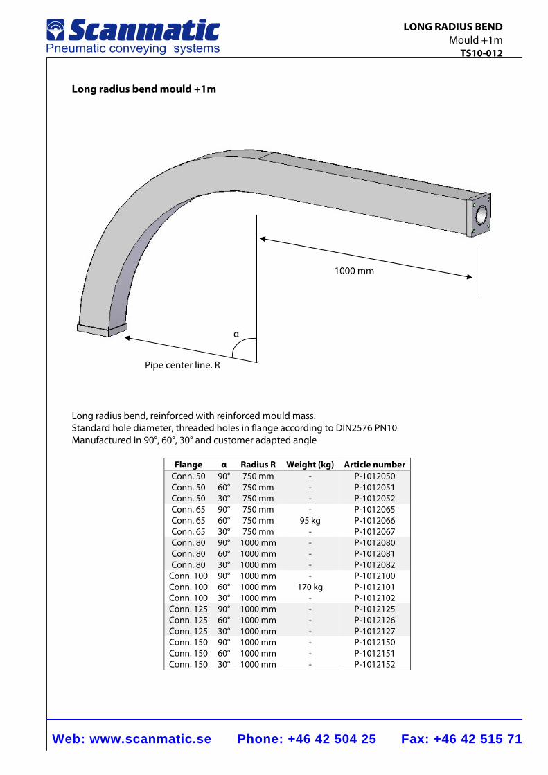
Web: www.scanmatic.se Phone: +46 42 504 25 Fax: +46 42 515 71
LONG RADIUS BEND Mould +1m TS10-012
Long radius bend mould +1m
Long radius bend, reinforced with reinforced mould mass. Standard hole diameter, threaded holes in flange according to DIN2576 PN10 Manufactured in 90°, 60°, 30° and customer adapted angle
Flange α Radius R Weight (kg) Article number Conn. 50 Conn. 50 Conn. 50
90°60° 30°
750 mm750 mm 750 mm
-- -
P-1012050 P-1012051 P-1012052
Conn. 65 Conn. 65 Conn. 65
90°60° 30°
750 mm750 mm 750 mm
-95 kg
-
P-1012065 P-1012066 P-1012067
Conn. 80 Conn. 80 Conn. 80
90°60° 30°
1000 mm1000 mm 1000 mm
-- -
P-1012080 P-1012081 P-1012082
Conn. 100 Conn. 100 Conn. 100
90°60° 30°
1000 mm1000 mm 1000 mm
-170 kg
-
P-1012100 P-1012101 P-1012102
Conn. 125 Conn. 125 Conn. 125
90°60° 30°
1000 mm1000 mm 1000 mm
-- -
P-1012125 P-1012126 P-1012127
Conn. 150 Conn. 150 Conn. 150
90°60° 30°
1000 mm1000 mm 1000 mm
-- -
P-1012150 P-1012151 P-1012152
Pipe center line. R
1000 mm
α
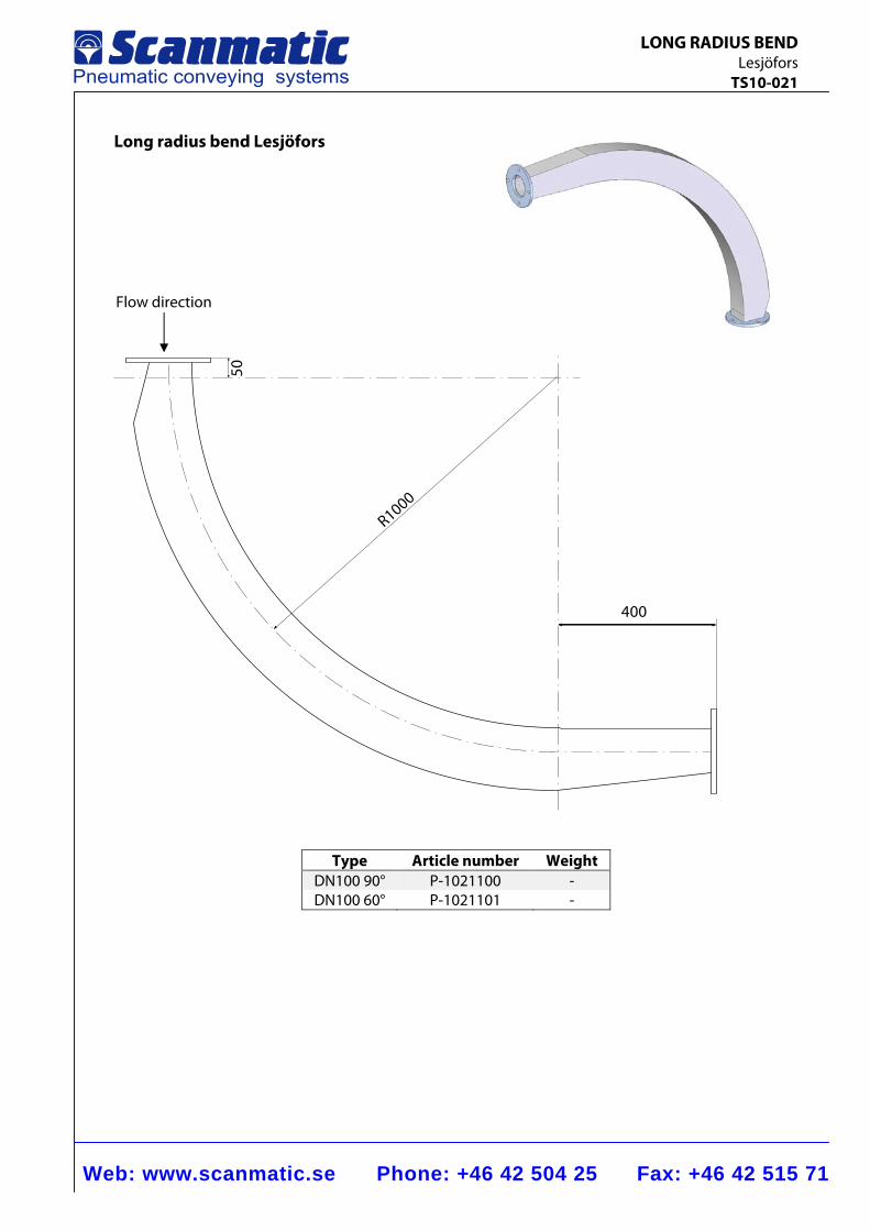
Web: www.scanmatic.se Phone: +46 42 504 25 Fax: +46 42 515 71
LONG RADIUS BEND Lesjöfors TS10-021
Long radius bend Lesjöfors
400
50
R1000
Type Article number Weight DN100 90° P-1021100 - DN100 60° P-1021101 -
Flow direction
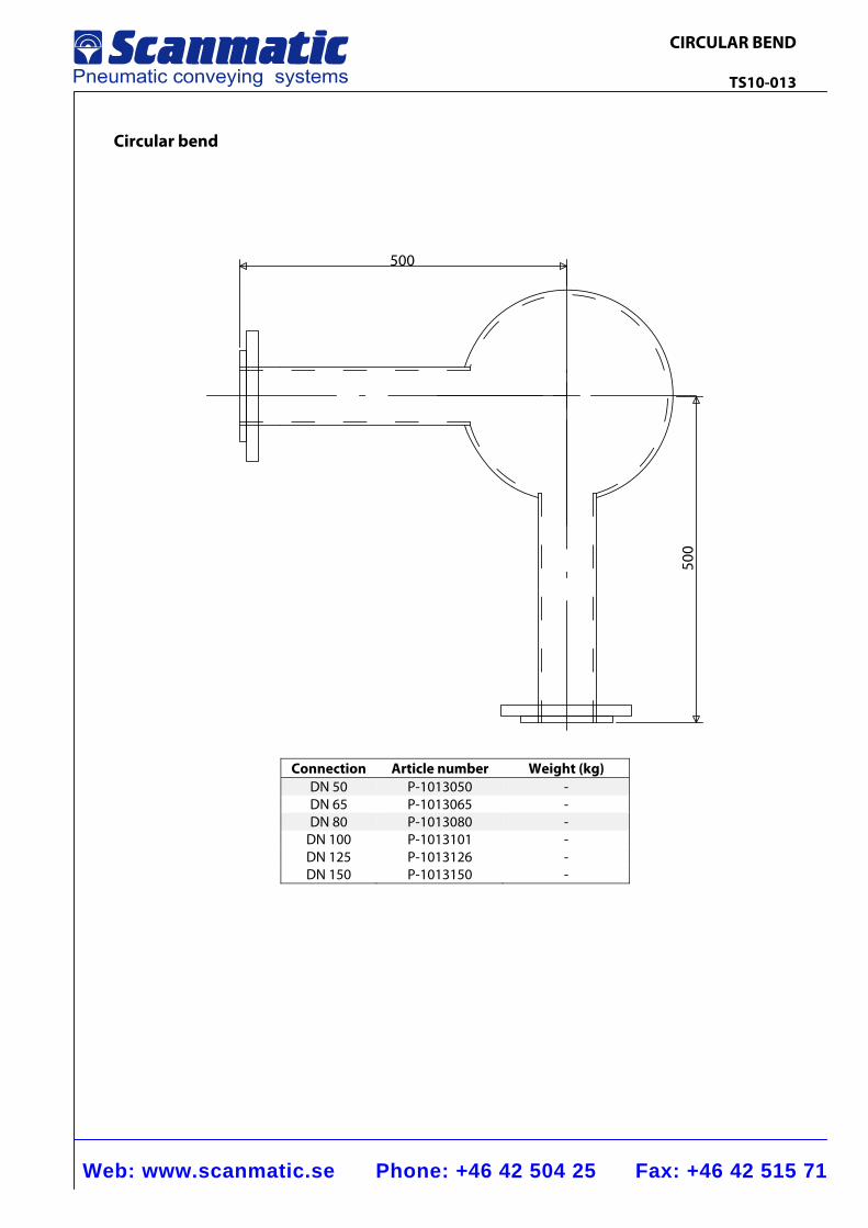
Web: www.scanmatic.se Phone: +46 42 504 25 Fax: +46 42 515 71
CIRCULAR BEND TS10-013
Circular bend
Connection Article number Weight (kg)DN 50 P-1013050 -DN 65 P-1013065 -DN 80 P-1013080 -
DN 100 P-1013101 -DN 125 P-1013126 -DN 150 P-1013150 -
500
500
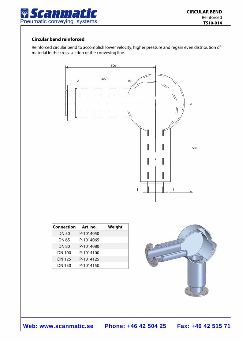
Web: www.scanmatic.se Phone: +46 42 504 25 Fax: +46 42 515 71
CIRCULAR BEND Reinforced TS10-014
Circular bend reinforced
Reinforced circular bend to accomplish lower velocity, higher pressure and regain even distribution of material in the cross-section of the conveying line.
500
500
300
Connection Art. no. Weight DN 50 P-1014050
DN 65 P-1014065
DN 80 P-1014080
DN 100 P-1014100
DN 125 P-1014125
DN 150 P-1014150
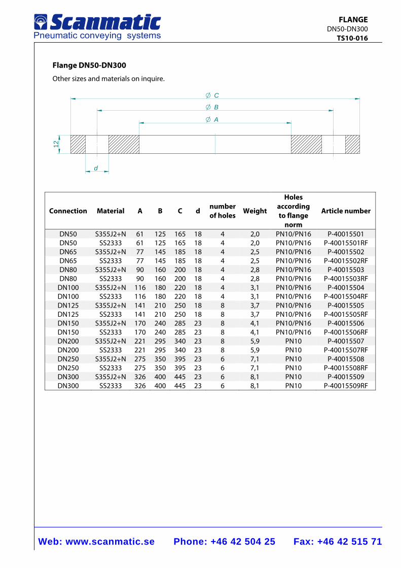
Web: www.scanmatic.se Phone: +46 42 504 25 Fax: +46 42 515 71
FLANGE DN50-DN300 TS10-016
Flange DN50-DN300
Other sizes and materials on inquire.
CO
BO
AO
12
d
Connection Material A B C d number of holes
Weight
Holes according to flange
norm
Article number
DN50 S355J2+N 61 125 165 18 4 2,0 PN10/PN16 P-40015501 DN50 SS2333 61 125 165 18 4 2,0 PN10/PN16 P-40015501RF DN65 S355J2+N 77 145 185 18 4 2,5 PN10/PN16 P-40015502 DN65 SS2333 77 145 185 18 4 2,5 PN10/PN16 P-40015502RF DN80 S355J2+N 90 160 200 18 4 2,8 PN10/PN16 P-40015503 DN80 SS2333 90 160 200 18 4 2,8 PN10/PN16 P-40015503RF
DN100 S355J2+N 116 180 220 18 4 3,1 PN10/PN16 P-40015504 DN100 SS2333 116 180 220 18 4 3,1 PN10/PN16 P-40015504RF DN125 S355J2+N 141 210 250 18 8 3,7 PN10/PN16 P-40015505 DN125 SS2333 141 210 250 18 8 3,7 PN10/PN16 P-40015505RF DN150 S355J2+N 170 240 285 23 8 4,1 PN10/PN16 P-40015506 DN150 SS2333 170 240 285 23 8 4,1 PN10/PN16 P-40015506RF DN200 S355J2+N 221 295 340 23 8 5,9 PN10 P-40015507 DN200 SS2333 221 295 340 23 8 5,9 PN10 P-40015507RF DN250 S355J2+N 275 350 395 23 6 7,1 PN10 P-40015508 DN250 SS2333 275 350 395 23 6 7,1 PN10 P-40015508RF DN300 S355J2+N 326 400 445 23 6 8,1 PN10 P-40015509 DN300 SS2333 326 400 445 23 6 8,1 PN10 P-40015509RF
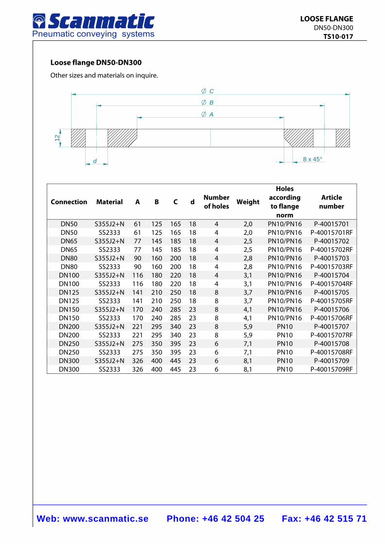
Web: www.scanmatic.se Phone: +46 42 504 25 Fax: +46 42 515 71
LOOSE FLANGE DN50-DN300 TS10-017
Loose flange DN50-DN300
Other sizes and materials on inquire.
8 x 45°
CO
BO
AO
12
d
Connection Material A B C d Number of holes Weight
Holes according to flange
norm
Article number
DN50 S355J2+N 61 125 165 18 4 2,0 PN10/PN16 P-40015701 DN50 SS2333 61 125 165 18 4 2,0 PN10/PN16 P-40015701RF DN65 S355J2+N 77 145 185 18 4 2,5 PN10/PN16 P-40015702 DN65 SS2333 77 145 185 18 4 2,5 PN10/PN16 P-40015702RF DN80 S355J2+N 90 160 200 18 4 2,8 PN10/PN16 P-40015703 DN80 SS2333 90 160 200 18 4 2,8 PN10/PN16 P-40015703RF
DN100 S355J2+N 116 180 220 18 4 3,1 PN10/PN16 P-40015704 DN100 SS2333 116 180 220 18 4 3,1 PN10/PN16 P-40015704RF DN125 S355J2+N 141 210 250 18 8 3,7 PN10/PN16 P-40015705 DN125 SS2333 141 210 250 18 8 3,7 PN10/PN16 P-40015705RF DN150 S355J2+N 170 240 285 23 8 4,1 PN10/PN16 P-40015706 DN150 SS2333 170 240 285 23 8 4,1 PN10/PN16 P-40015706RF DN200 S355J2+N 221 295 340 23 8 5,9 PN10 P-40015707 DN200 SS2333 221 295 340 23 8 5,9 PN10 P-40015707RF DN250 S355J2+N 275 350 395 23 6 7,1 PN10 P-40015708 DN250 SS2333 275 350 395 23 6 7,1 PN10 P-40015708RF DN300 S355J2+N 326 400 445 23 6 8,1 PN10 P-40015709 DN300 SS2333 326 400 445 23 6 8,1 PN10 P-40015709RF
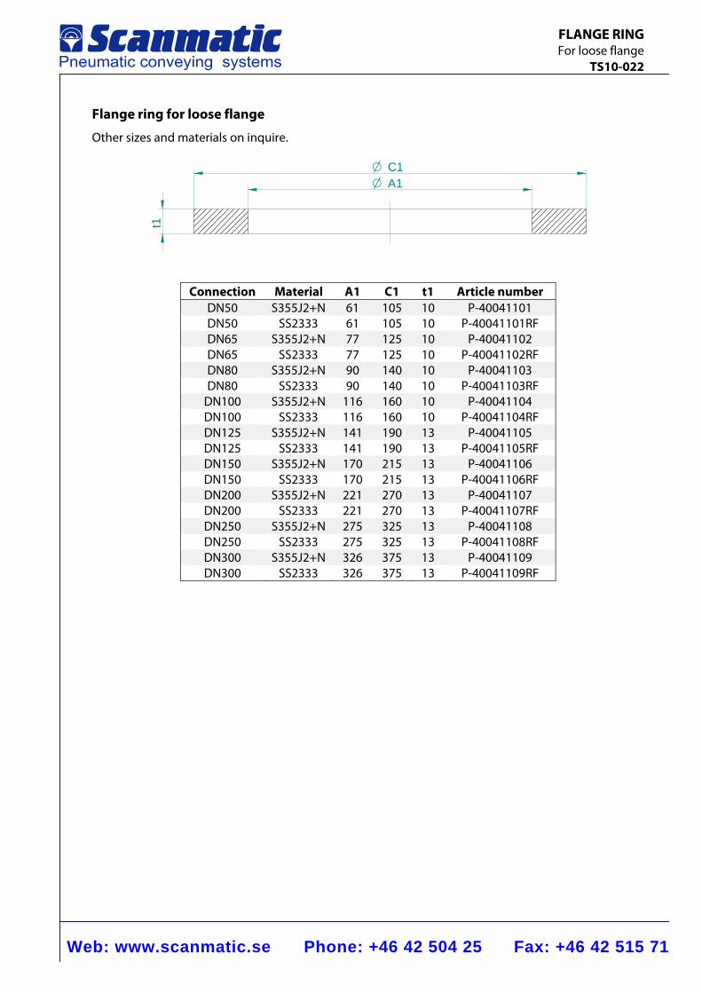
Web: www.scanmatic.se Phone: +46 42 504 25 Fax: +46 42 515 71
FLANGE RING For loose flange TS10-022
Flange ring for loose flange
Other sizes and materials on inquire.
t1
A1OC1O
Connection Material A1 C1 t1 Article number DN50 S355J2+N 61 105 10 P-40041101 DN50 SS2333 61 105 10 P-40041101RF DN65 S355J2+N 77 125 10 P-40041102 DN65 SS2333 77 125 10 P-40041102RF DN80 S355J2+N 90 140 10 P-40041103 DN80 SS2333 90 140 10 P-40041103RF
DN100 S355J2+N 116 160 10 P-40041104 DN100 SS2333 116 160 10 P-40041104RF DN125 S355J2+N 141 190 13 P-40041105 DN125 SS2333 141 190 13 P-40041105RF DN150 S355J2+N 170 215 13 P-40041106 DN150 SS2333 170 215 13 P-40041106RF DN200 S355J2+N 221 270 13 P-40041107 DN200 SS2333 221 270 13 P-40041107RF DN250 S355J2+N 275 325 13 P-40041108 DN250 SS2333 275 325 13 P-40041108RF DN300 S355J2+N 326 375 13 P-40041109 DN300 SS2333 326 375 13 P-40041109RF
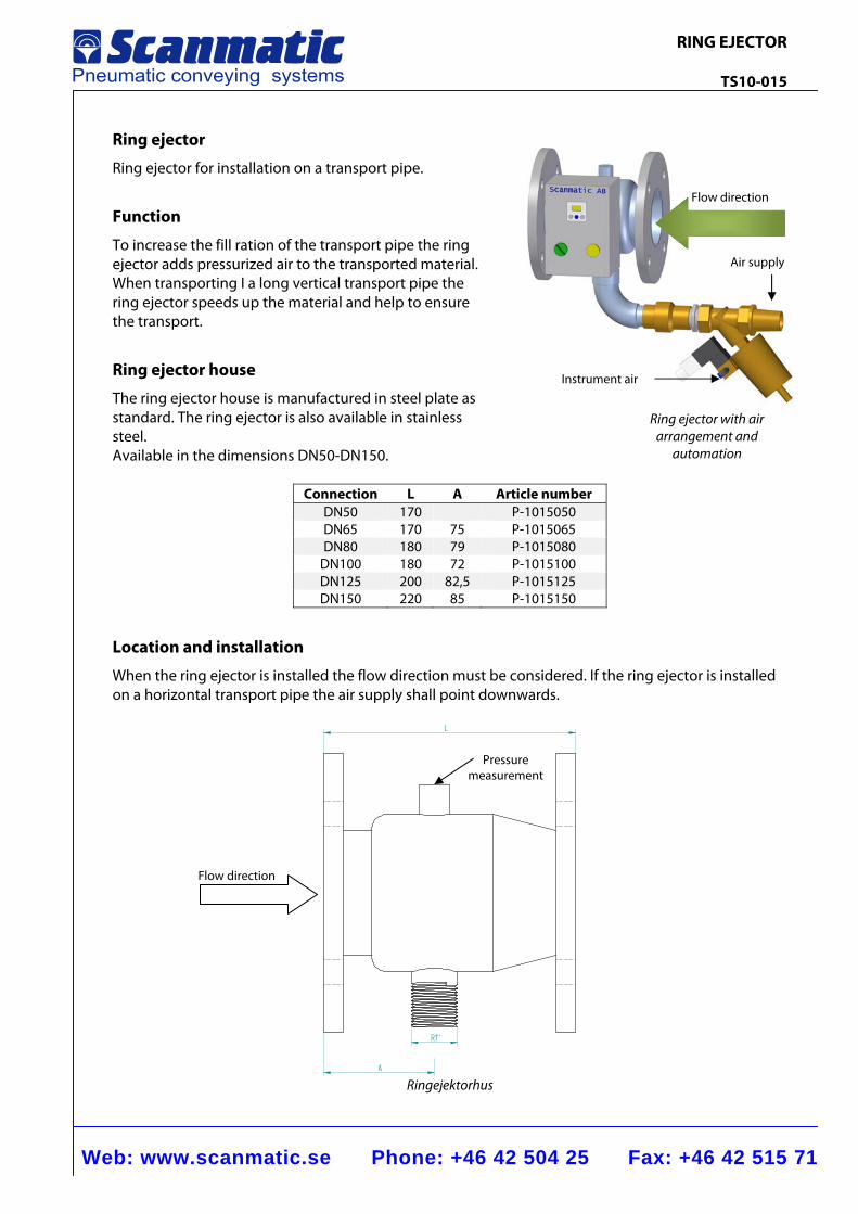
Web: www.scanmatic.se Phone: +46 42 504 25 Fax: +46 42 515 71
RING EJECTOR TS10-015
Flow direction
Instrument air
Air supply
Ring ejector with air arrangement and
automation
Ring ejector
Ring ejector for installation on a transport pipe.
Function
To increase the fill ration of the transport pipe the ring ejector adds pressurized air to the transported material. When transporting I a long vertical transport pipe the ring ejector speeds up the material and help to ensure the transport.
Ring ejector house
The ring ejector house is manufactured in steel plate as standard. The ring ejector is also available in stainless steel. Available in the dimensions DN50-DN150.
Connection L A Article numberDN50 170 P-1015050DN65 170 75 P-1015065DN80 180 79 P-1015080
DN100 180 72 P-1015100DN125 200 82,5 P-1015125DN150 220 85 P-1015150
Location and installation
When the ring ejector is installed the flow direction must be considered. If the ring ejector is installed on a horizontal transport pipe the air supply shall point downwards.
L
R1”
A Ringejektorhus
Pressure measurement
Flow direction
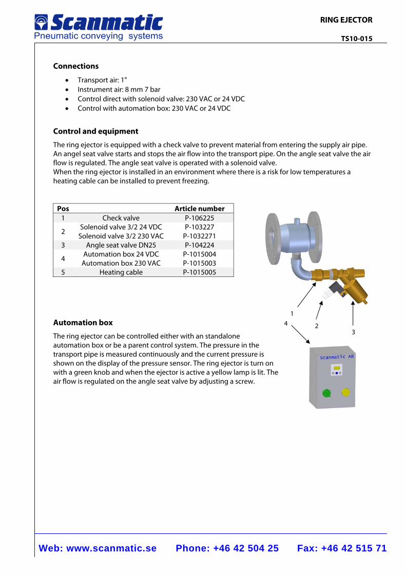
Web: www.scanmatic.se Phone: +46 42 504 25 Fax: +46 42 515 71
RING EJECTOR TS10-015
1
2 3
Connections
• Transport air: 1" • Instrument air: 8 mm 7 bar • Control direct with solenoid valve: 230 VAC or 24 VDC • Control with automation box: 230 VAC or 24 VDC
Control and equipment
The ring ejector is equipped with a check valve to prevent material from entering the supply air pipe. An angel seat valve starts and stops the air flow into the transport pipe. On the angle seat valve the air flow is regulated. The angle seat valve is operated with a solenoid valve. When the ring ejector is installed in an environment where there is a risk for low temperatures a heating cable can be installed to prevent freezing.
Pos Article number 1 Check valve P-106225
2 Solenoid valve 3/2 24 VDC
Solenoid valve 3/2 230 VAC P-103227
P-1032271 3 Angle seat valve DN25 P-104224
4 Automation box 24 VDC Automation box 230 VAC
P-1015004 P-1015003
5 Heating cable P-1015005
Automation box
The ring ejector can be controlled either with an standalone automation box or be a parent control system. The pressure in the transport pipe is measured continuously and the current pressure is shown on the display of the pressure sensor. The ring ejector is turn on with a green knob and when the ejector is active a yellow lamp is lit. The air flow is regulated on the angle seat valve by adjusting a screw.
4
SAFTEY VALVES
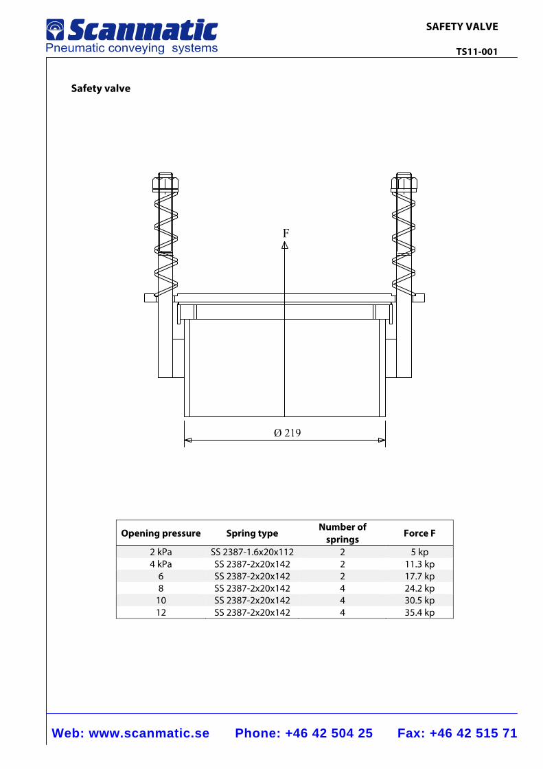
Web: www.scanmatic.se Phone: +46 42 504 25 Fax: +46 42 515 71
SAFETY VALVE TS11-001
Safety valve
Opening pressure Spring type Number of
springs Force F
2 kPa SS 2387-1.6x20x112 2 5 kp 4 kPa SS 2387-2x20x142 2 11.3 kp
6 SS 2387-2x20x142 2 17.7 kp 8 SS 2387-2x20x142 4 24.2 kp
10 SS 2387-2x20x142 4 30.5 kp 12 SS 2387-2x20x142 4 35.4 kp
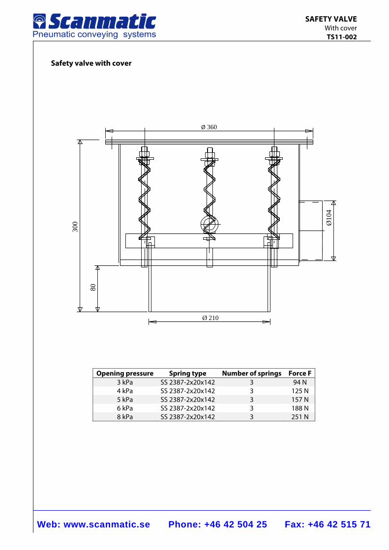
Web: www.scanmatic.se Phone: +46 42 504 25 Fax: +46 42 515 71
SAFETY VALVE With cover TS11-002
Safety valve with cover
Ø 360
Ø 210
300
80
Ø10
4
Opening pressure Spring type Number of springs Force F 3 kPa SS 2387-2x20x142 3 94 N 4 kPa SS 2387-2x20x142 3 125 N 5 kPa SS 2387-2x20x142 3 157 N 6 kPa SS 2387-2x20x142 3 188 N 8 kPa SS 2387-2x20x142 3 251 N
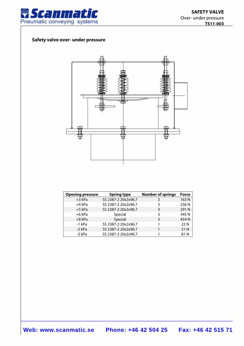
Web: www.scanmatic.se Phone: +46 42 504 25 Fax: +46 42 515 71
SAFETY VALVE Over- under pressure TS11-003
Safety valve over- under pressure
Opening pressure Spring type Number of springs Force +3 kPa SS 2387-2 20x2x96.7 3 163 N +4 kPa SS 2387-2 20x2x96.7 3 236 N +5 kPa SS 2387-2 20x2x96.7 3 291 N +6 kPa Special 3 345 N +8 kPa Special 3 454 N -1 kPa SS 2387-2 20x2x96.7 1 22 N -2 kPa SS 2387-2 20x2x96.7 1 51 N -3 kPa SS 2387-2 20x2x96.7 1 81 N
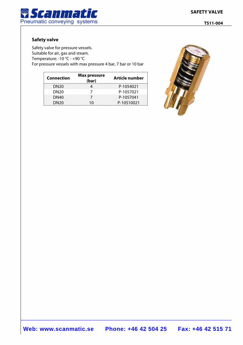
Web: www.scanmatic.se Phone: +46 42 504 25 Fax: +46 42 515 71
SAFETY VALVE TS11-004
Safety valve
Safety valve for pressure vessels. Suitable for air, gas and steam. Temperature: -10 °C - +90 °C For pressure vessels with max pressure 4 bar, 7 bar or 10 bar
Connection Max pressure
(bar) Article number
DN20 4 P-1054021 DN20 7 P-1057021 DN40 7 P-1057041 DN20 10 P-10510021
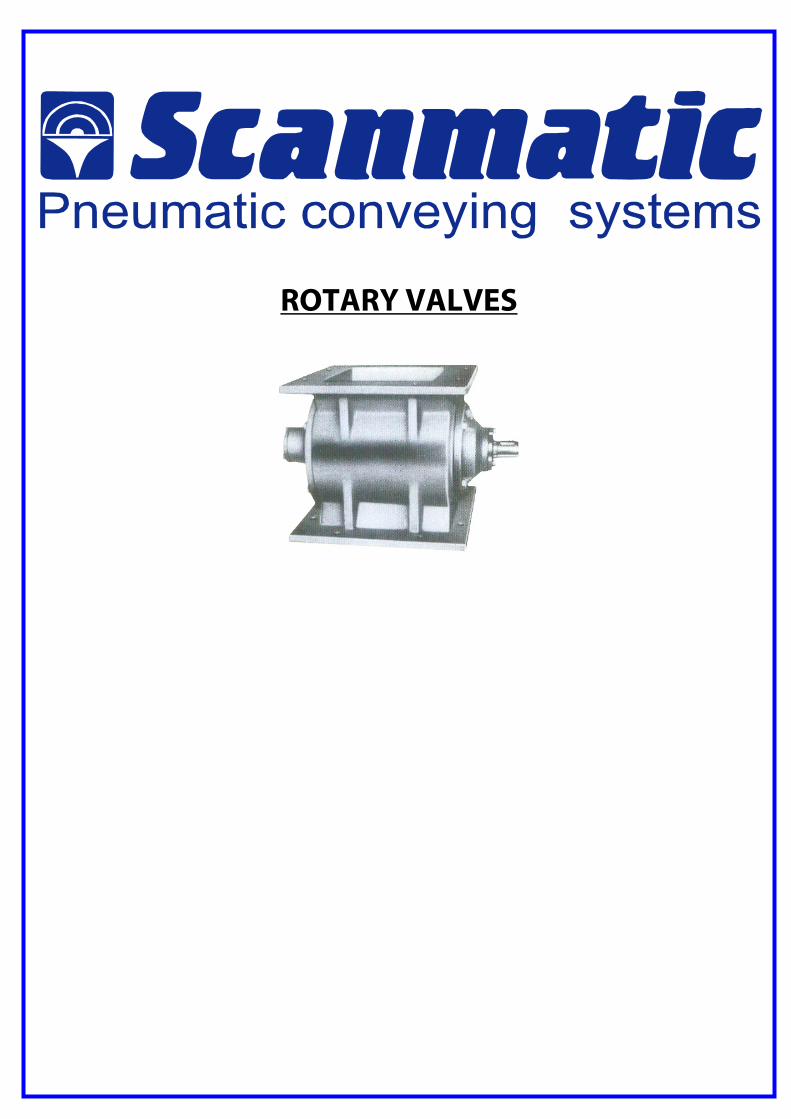
ROTARY VALVES
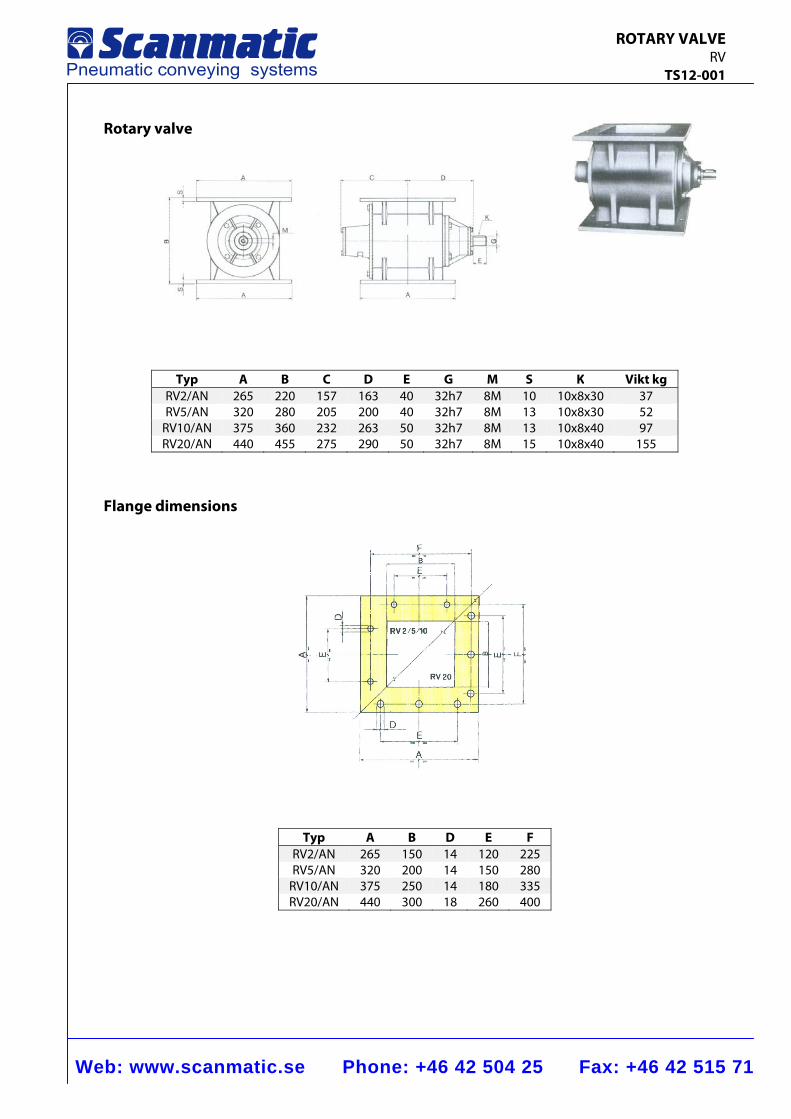
Web: www.scanmatic.se Phone: +46 42 504 25 Fax: +46 42 515 71
ROTARY VALVE RV TS12-001
Rotary valve
Typ A B C D E G M S K Vikt kgRV2/AN 265 220 157 163 40 32h7 8M 10 10x8x30 37 RV5/AN 320 280 205 200 40 32h7 8M 13 10x8x30 52
RV10/AN 375 360 232 263 50 32h7 8M 13 10x8x40 97 RV20/AN 440 455 275 290 50 32h7 8M 15 10x8x40 155
Flange dimensions
Typ A B D E FRV2/AN 265 150 14 120 225RV5/AN 320 200 14 150 280
RV10/AN 375 250 14 180 335RV20/AN 440 300 18 260 400

MISCELLANEOUS EQUIPMENT AND ACCESSORIES
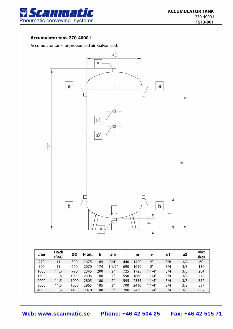
Web: www.scanmatic.se Phone: +46 42 504 25 Fax: +46 42 515 71
ACCUMULATOR TANK 270-4000 l TS13-001
Accumulator tank 270-4000 l
Accumulator tank for pressurized air. Galvanized.
v
v
u1
u2
Liter Tryck (Bar)
ØD H tot. h a-b l m v u1 u2 vikt (kg)
270 11 500 1675 189 3/4" 440 1420 2" 3/8 1/4 60500 11 600 2070 174 1 1/2" 690 1690 2" 3/4 3/8 130
1000 11,5 790 2345 200 2" 725 1725 1 1/4" 3/4 3/8 2041500 11,5 1000 2305 180 2" 590 1860 1 1/4" 3/4 3/8 2782000 11,5 1000 2805 180 2" 595 2355 1 1/4" 3/4 3/8 3523000 11,5 1200 2965 185 3" 700 2410 1 1/4" 3/4 3/8 5374000 11,5 1450 3070 180 3" 780 2430 1 1/4" 3/4 3/8 802
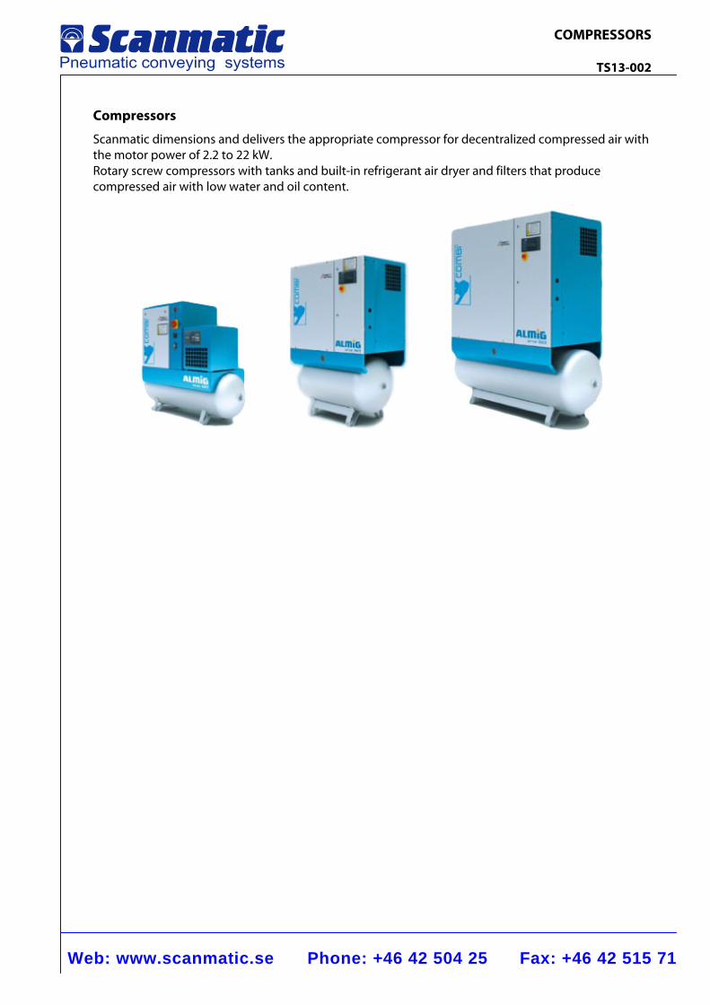
Web: www.scanmatic.se Phone: +46 42 504 25 Fax: +46 42 515 71
COMPRESSORS TS13-002
Compressors
Scanmatic dimensions and delivers the appropriate compressor for decentralized compressed air with the motor power of 2.2 to 22 kW. Rotary screw compressors with tanks and built-in refrigerant air dryer and filters that produce compressed air with low water and oil content.
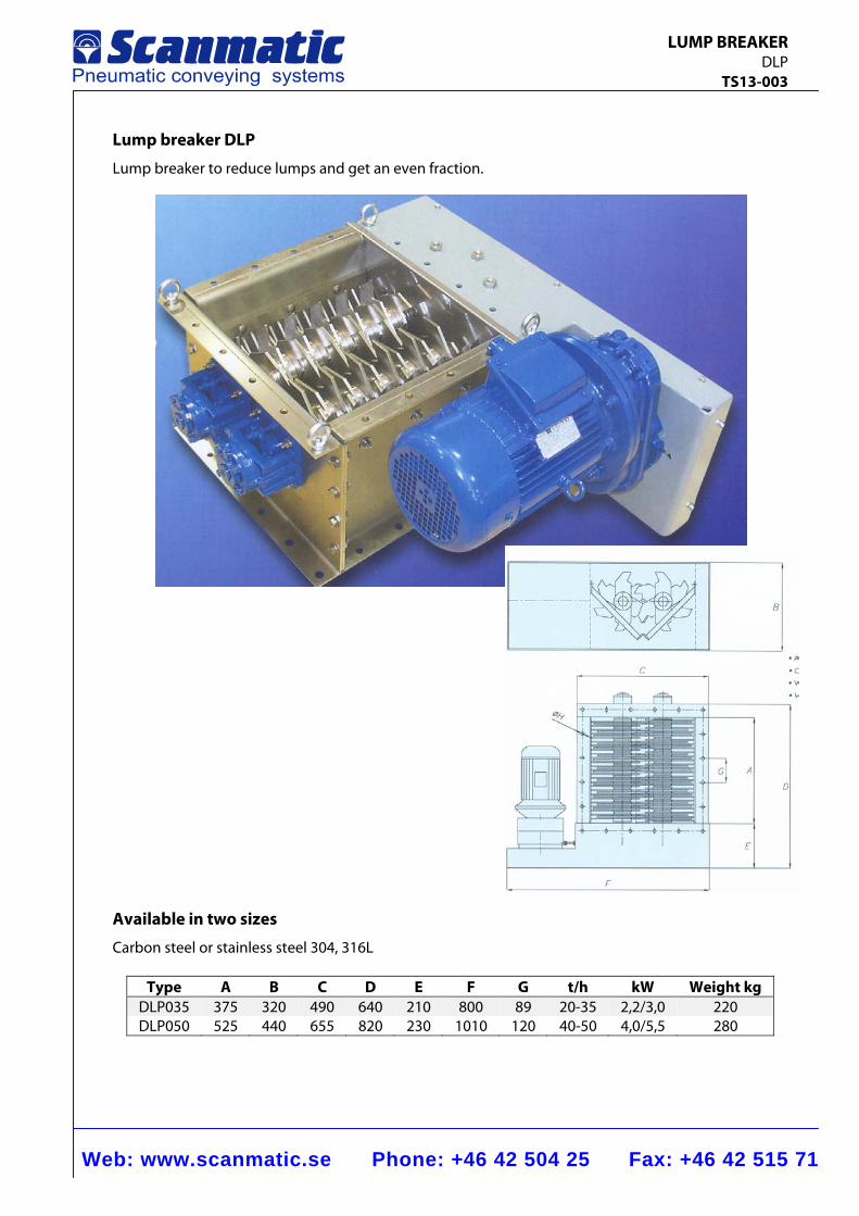
Web: www.scanmatic.se Phone: +46 42 504 25 Fax: +46 42 515 71
LUMP BREAKER DLP TS13-003
Lump breaker DLP
Lump breaker to reduce lumps and get an even fraction.
Available in two sizes
Carbon steel or stainless steel 304, 316L
Type A B C D E F G t/h kW Weight kg DLP035 375 320 490 640 210 800 89 20-35 2,2/3,0 220 DLP050 525 440 655 820 230 1010 120 40-50 4,0/5,5 280
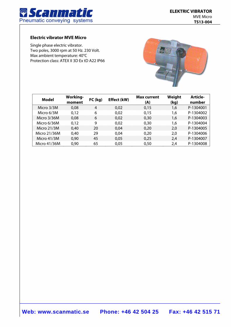
Web: www.scanmatic.se Phone: +46 42 504 25 Fax: +46 42 515 71
ELEKTRIC VIBRATOR MVE Micro TS13-004
Electric vibrator MVE Micro
Single phase electric vibrator. Two poles, 3000 rpm at 50 Hz. 230 Volt. Max ambient temperature: 40°C Protection class: ATEX II 3D Ex tD A22 IP66
Model Working- moment FC (kg) Effect (kW)
Max current (A)
Weight (kg)
Article- number
Micro 3/3M 0,08 4 0,02 0,15 1,6 P-1304001 Micro 6/3M 0,12 6 0,02 0,15 1,6 P-1304002
Micro 3/36M 0,08 6 0,02 0,30 1,6 P-1304003 Micro 6/36M 0,12 9 0,02 0,30 1,6 P-1304004 Micro 21/3M 0,40 20 0,04 0,20 2,0 P-1304005
Micro 21/36M 0,40 29 0,04 0,20 2,0 P-1304006 Micro 41/3M 0,90 45 0,05 0,25 2,4 P-1304007
Micro 41/36M 0,90 65 0,05 0,50 2,4 P-1304008
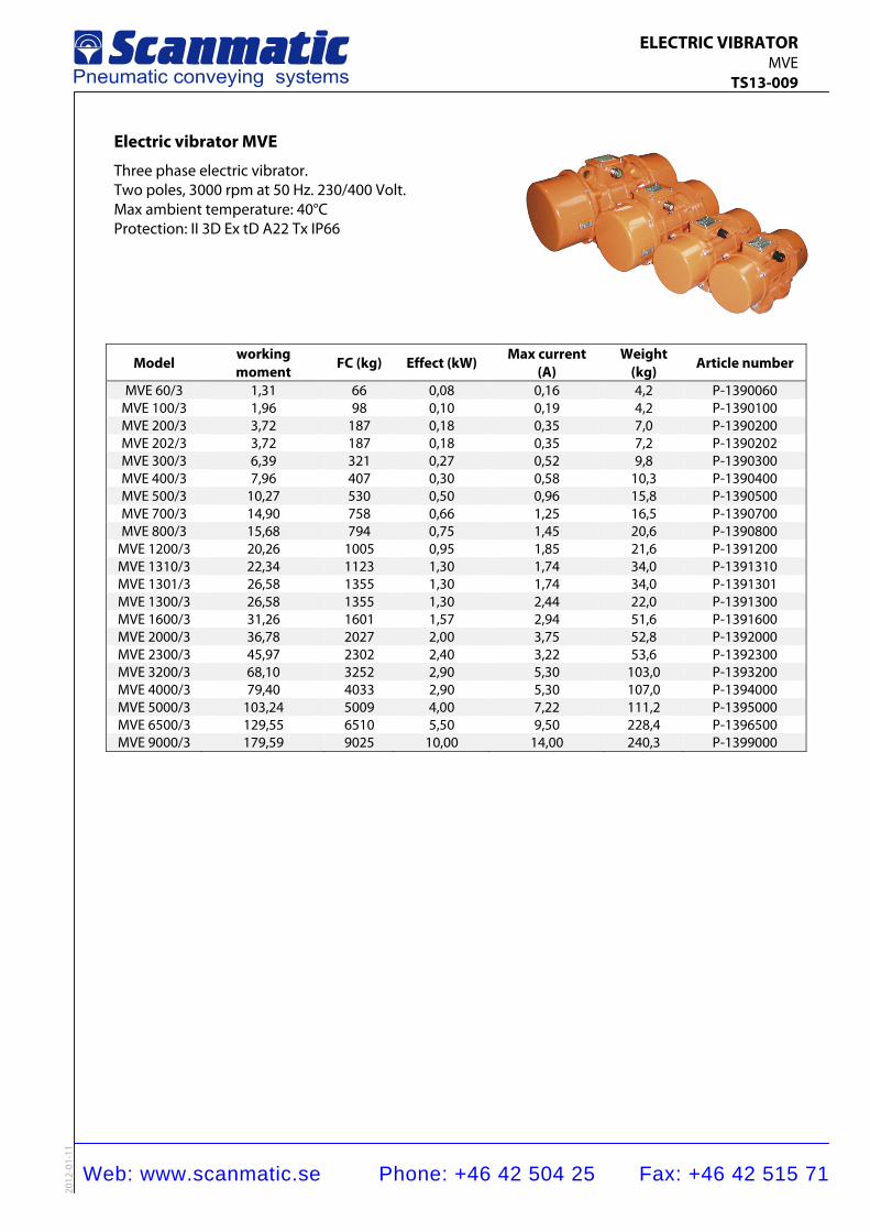
Web: www.scanmatic.se Phone: +46 42 504 25 Fax: +46 42 515 71
ELECTRIC VIBRATOR MVE TS13-009
2012
-01-
11
Electric vibrator MVE
Three phase electric vibrator. Two poles, 3000 rpm at 50 Hz. 230/400 Volt. Max ambient temperature: 40°C Protection: II 3D Ex tD A22 Tx IP66
Model working moment
FC (kg) Effect (kW) Max current(A)
Weight (kg)
Article number
MVE 60/3 1,31 66 0,08 0,16 4,2 P-1390060MVE 100/3 1,96 98 0,10 0,19 4,2 P-1390100MVE 200/3 3,72 187 0,18 0,35 7,0 P-1390200MVE 202/3 3,72 187 0,18 0,35 7,2 P-1390202MVE 300/3 6,39 321 0,27 0,52 9,8 P-1390300MVE 400/3 7,96 407 0,30 0,58 10,3 P-1390400MVE 500/3 10,27 530 0,50 0,96 15,8 P-1390500MVE 700/3 14,90 758 0,66 1,25 16,5 P-1390700MVE 800/3 15,68 794 0,75 1,45 20,6 P-1390800
MVE 1200/3 20,26 1005 0,95 1,85 21,6 P-1391200MVE 1310/3 22,34 1123 1,30 1,74 34,0 P-1391310MVE 1301/3 26,58 1355 1,30 1,74 34,0 P-1391301MVE 1300/3 26,58 1355 1,30 2,44 22,0 P-1391300MVE 1600/3 31,26 1601 1,57 2,94 51,6 P-1391600MVE 2000/3 36,78 2027 2,00 3,75 52,8 P-1392000MVE 2300/3 45,97 2302 2,40 3,22 53,6 P-1392300MVE 3200/3 68,10 3252 2,90 5,30 103,0 P-1393200MVE 4000/3 79,40 4033 2,90 5,30 107,0 P-1394000MVE 5000/3 103,24 5009 4,00 7,22 111,2 P-1395000MVE 6500/3 129,55 6510 5,50 9,50 228,4 P-1396500MVE 9000/3 179,59 9025 10,00 14,00 240,3 P-1399000
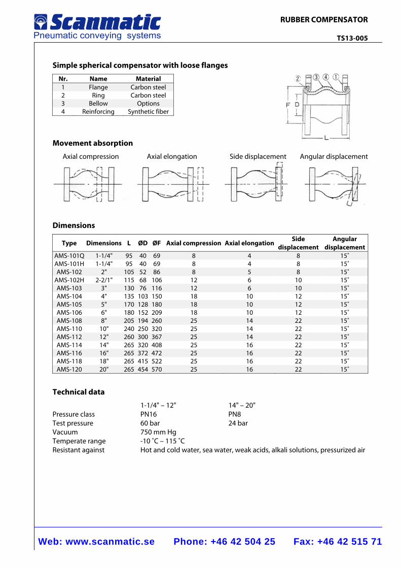
Web: www.scanmatic.se Phone: +46 42 504 25 Fax: +46 42 515 71
RUBBER COMPENSATOR TS13-005
Simple spherical compensator with loose flanges
Nr. Name Material 1 Flange Carbon steel2 Ring Carbon steel3 Bellow Options 4 Reinforcing Synthetic fiber
Movement absorption
Axial compression Axial elongation Side displacement Angular displacement
Dimensions
Type Dimensions L ØD ØF Axial compression Axial elongation Side displacement
Angular displacement
AMS-101Q 1-1/4" 95 40 69 8 4 8 15˚AMS-101H 1-1/4" 95 40 69 8 4 8 15˚AMS-102 2" 105 52 86 8 5 8 15˚
AMS-102H 2-2/1" 115 68 106 12 6 10 15˚AMS-103 3" 130 76 116 12 6 10 15˚AMS-104 4" 135 103 150 18 10 12 15˚AMS-105 5" 170 128 180 18 10 12 15˚AMS-106 6" 180 152 209 18 10 12 15˚AMS-108 8" 205 194 260 25 14 22 15˚AMS-110 10" 240 250 320 25 14 22 15˚AMS-112 12" 260 300 367 25 14 22 15˚AMS-114 14" 265 320 408 25 16 22 15˚AMS-116 16" 265 372 472 25 16 22 15˚AMS-118 18" 265 415 522 25 16 22 15˚AMS-120 20" 265 454 570 25 16 22 15˚
Technical data
1-1/4" – 12" 14" – 20" Pressure class PN16 PN8 Test pressure 60 bar 24 bar Vacuum 750 mm Hg Temperate range -10 ˚C – 115 ˚C Resistant against Hot and cold water, sea water, weak acids, alkali solutions, pressurized air
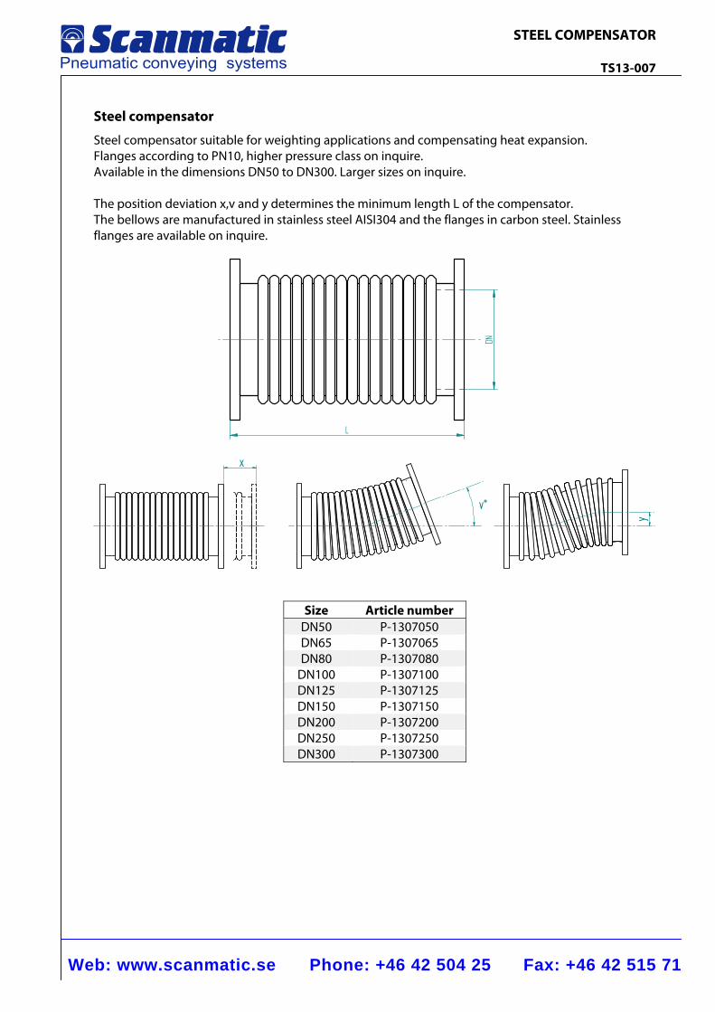
Web: www.scanmatic.se Phone: +46 42 504 25 Fax: +46 42 515 71
STEEL COMPENSATOR TS13-007
Steel compensator
Steel compensator suitable for weighting applications and compensating heat expansion. Flanges according to PN10, higher pressure class on inquire. Available in the dimensions DN50 to DN300. Larger sizes on inquire. The position deviation x,v and y determines the minimum length L of the compensator. The bellows are manufactured in stainless steel AISI304 and the flanges in carbon steel. Stainless flanges are available on inquire.
L
DN
x
v°
y
Size Article number DN50 P-1307050 DN65 P-1307065 DN80 P-1307080
DN100 P-1307100 DN125 P-1307125 DN150 P-1307150 DN200 P-1307200 DN250 P-1307250 DN300 P-1307300
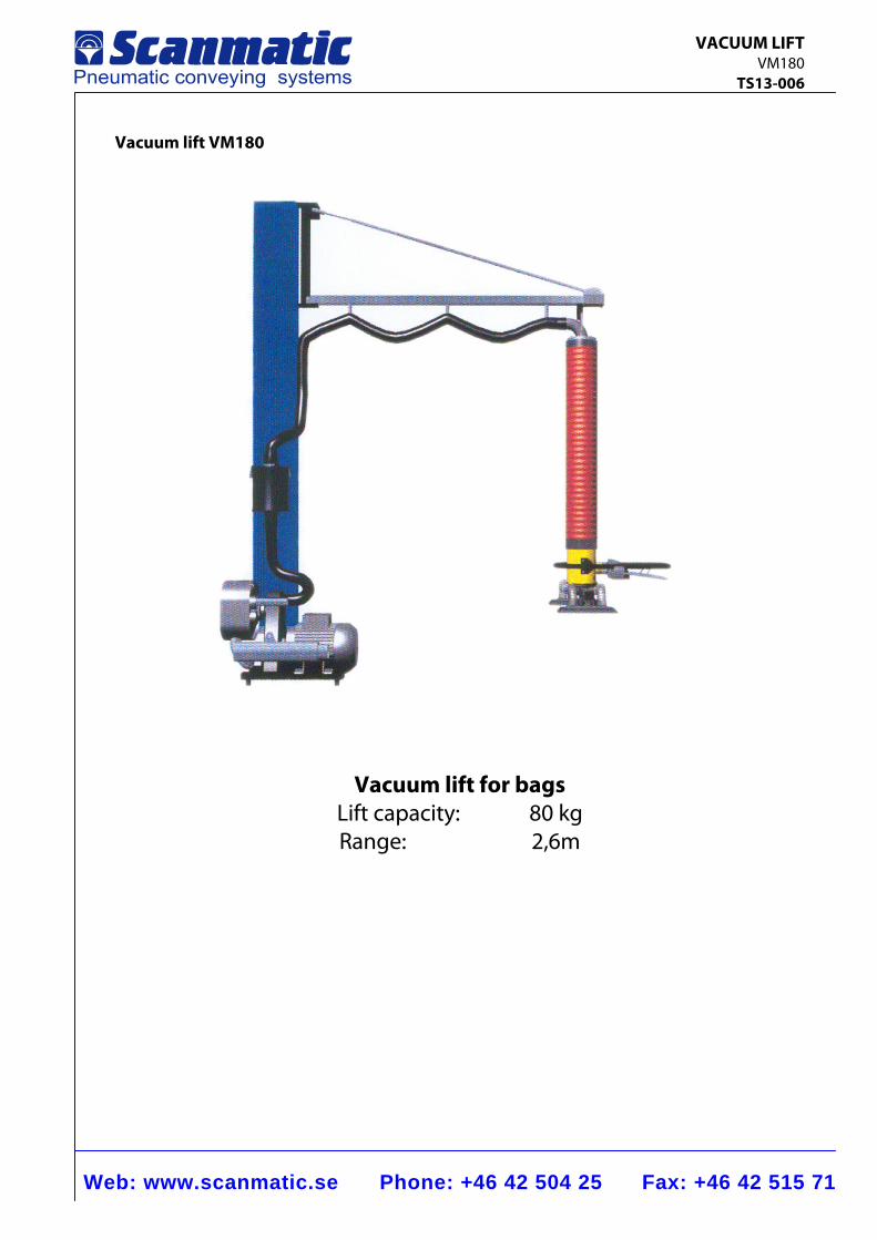
Web: www.scanmatic.se Phone: +46 42 504 25 Fax: +46 42 515 71
VACUUM LIFT VM180 TS13-006
Vacuum lift VM180
Vacuum lift for bags
Lift capacity: 80 kg Range: 2,6m