Embed Size (px)
Citation preview
tel +27 11 974 2425fax +27 11 974 2443web www.europair-africa.comemail: [email protected]
Europair Africa (Pty) Ltd(a div. of First Strut)
Cnr. Grader and VuurslagSpartan Ext. 3
Kempton ParkJohannesburg
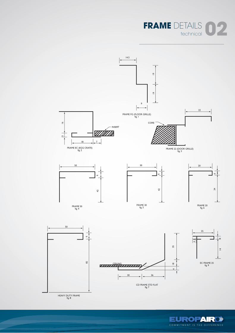
FRAME & FIXING DETAILStechnical
C O M M I T M E N T I S T H E D I F F E R E N C E
technical
FRAME DETAILS 02
C O M M I T M E N T I S T H E D I F F E R E N C E
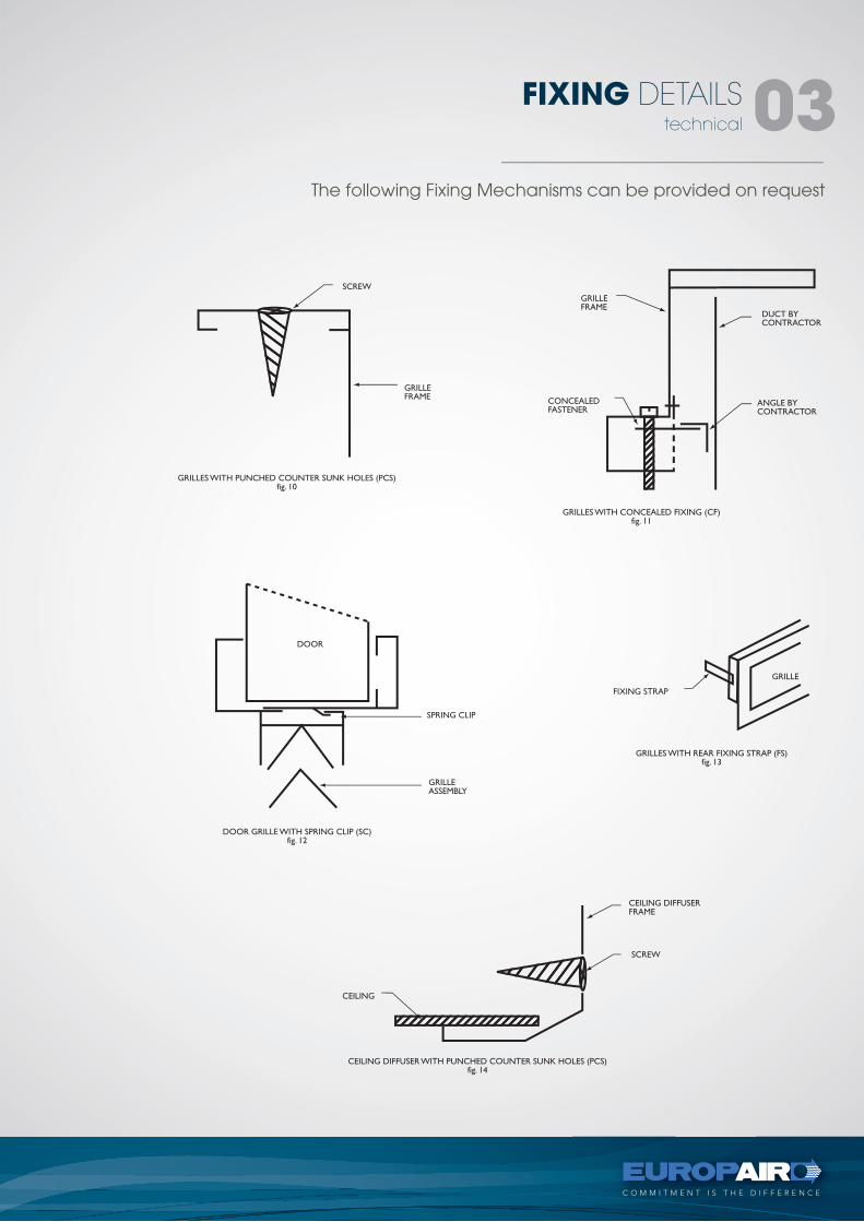
The following Fixing Mechanisms can be provided on request
technical
FIXING DETAILS 03
tel +27 11 974 2425fax +27 11 974 2443web www.europair-africa.comemail: [email protected]
Europair Africa (Pty) Ltd(a div. of First Strut)
Cnr. Grader and VuurslagSpartan Ext. 3
Kempton ParkJohannesburg
CEILING DIFFUSERStechnical
types -CD, CAB
C O M M I T M E N T I S T H E D I F F E R E N C E
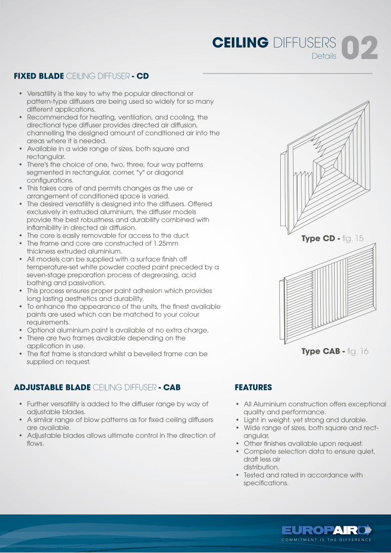
ADJUSTABLE BLADE CEILING DIFFUSER - CAB
FIXED BLADE CEILING DIFFUSER - CD
FEATURES
• All Aluminium construction offers exceptional quality and performance.
• Light in weight. yet strong and durable.• Wide range of sizes, both square and rect-
angular,• Other finishes available upon request.• Complete selection data to ensure quiet,
draft less airdistribution.
• Tested and rated in accordance with specifications.
• Versatility is the key to why the popular directional or pattern-type diffusers are being used so widely for so many different applications.
• Recommended for heating, ventilation, and cooling, the directional type diffuser provides directed air diffusion, channelling the designed amount of conditioned air into the areas where it is needed.
• Available in a wide range of sizes, both square andrectangular.
• There's the choice of one, two, three, four way patterns segmented in rectangular, corner, "y" or diagonal configurations.
• This takes care of and permits changes as the use or arrangement of conditioned space is varied.
• The desired versatility is designed into the diffusers. Offered exclusively in extruded aluminium, the diffuser models provide the best robustness and durability combined with inflamibility in directed air diffusion.
• The core is easily removable for access to the duct.• The frame and core are constructed of 1.25mm
thickness extruded aluminium.• All models can be supplied with a surface finish off
temperature-set white powder coated paint preceded by a seven-stage preparation process of degreasing, acidbathing and passivation.
• This process ensures proper paint adhesion which provides long lasting aesthetics and durability.
• To enhance the appearance of the units, the finest available paints are used which can be matched to your colour requirements.
• Optional aluminium paint is available at no extra charge.• There are two frames available depending on the
application in use.• The flat frame is standard whilst a bevelled frame can be
supplied on request.
• Further versatility is added to the diffuser range by way of adjustable blades.
• A similar range of blow patterns as for fixed ceiling diffusers are available.
• Adjustable blades allows ultimate control in the direction of flows.
Details
CEILING DIFFUSERS 02
Patterns Requirement
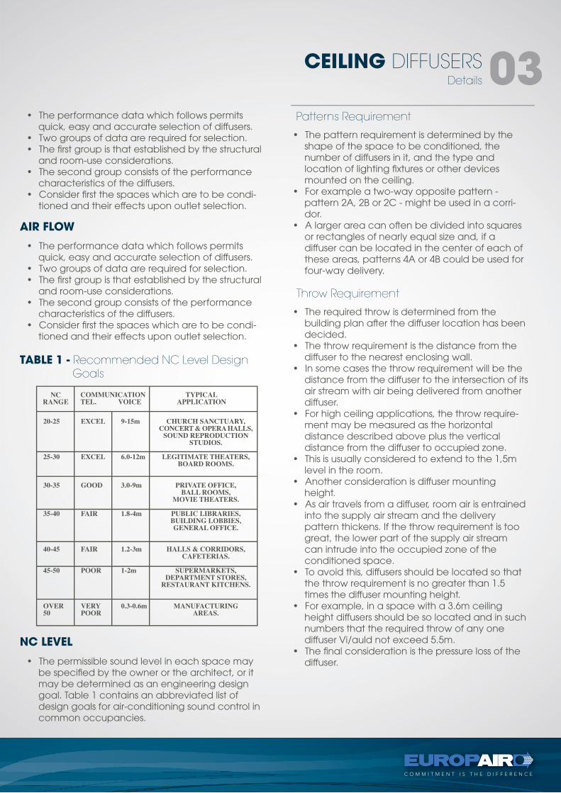
TABLE 1 - Recommended NC Level Design Goals
AIR FLOW
NC LEVEL
• The performance data which follows permits quick, easy and accurate selection of diffusers.
• Two groups of data are required for selection.• The first group is that established by the structural
and room-use considerations.• The second group consists of the performance
characteristics of the diffusers.• Consider first the spaces which are to be condi-
tioned and their effects upon outlet selection.
• The pattern requirement is determined by the shape of the space to be conditioned, the number of diffusers in it, and the type and location of lighting fixtures or other devices mounted on the ceiling.
• For example a two-way opposite pattern - pattern 2A, 2B or 2C - might be used in a corri-dor.
• A larger area can often be divided into squares or rectangles of nearly equal size and, if a diffuser can be located in the center of each of these areas, patterns 4A or 4B could be used for four-way delivery.
Throw Requirement
• The required throw is determined from the building plan after the diffuser location has been decided.
• The throw requirement is the distance from the diffuser to the nearest enclosing wall.
• In some cases the throw requirement will be the distance from the diffuser to the intersection of its air stream with air being delivered from another diffuser.
• For high ceiling applications, the throw require-ment may be measured as the horizontal distance described above plus the vertical distance from the diffuser to occupied zone.
• This is usually considered to extend to the 1,5m level in the room.
• Another consideration is diffuser mounting height.
• As air travels from a diffuser, room air is entrained into the supply air stream and the delivery pattern thickens. If the throw requirement is too great, the lower part of the supply air stream can intrude into the occupied zone of the conditioned space.
• To avoid this, diffusers should be located so that the throw requirement is no greater than 1.5 times the diffuser mounting height.
• For example, in a space with a 3.6m ceiling height diffusers should be so located and in such numbers that the required throw of any one diffuser Vi/auld not exceed 5.5m.
• The final consideration is the pressure loss of the diffuser.
• The performance data which follows permits quick, easy and accurate selection of diffusers.
• Two groups of data are required for selection.• The first group is that established by the structural
and room-use considerations.• The second group consists of the performance
characteristics of the diffusers.• Consider first the spaces which are to be condi-
tioned and their effects upon outlet selection.
• The permissible sound level in each space may be specified by the owner or the architect, or it may be determined as an engineering design goal. Table 1 contains an abbreviated list of design goals for air-conditioning sound control in common occupancies.
Details
CEILING DIFFUSERS 03
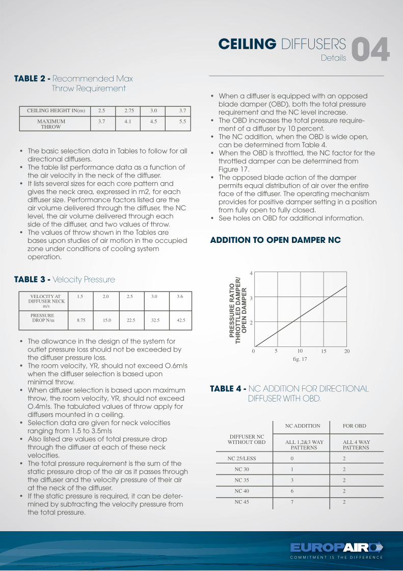
TABLE 2 - Recommended Max Throw Requirement
TABLE 3 - Velocity Pressure
ADDITION TO OPEN DAMPER NC
TABLE 4 - NC ADDITION FOR DIRECTIONAL DIFFUSER WITH OBD.
• The basic selection data in Tables to follow for all directional diffusers.
• The table list performance data as a function of the air velocity in the neck of the diffuser.
• It lists several sizes for each core pattern and gives the neck area, expressed in m2, for each diffuser size. Performance factors listed are the air volume delivered through the diffuser, the NC level, the air volume delivered through each side of the diffuser, and two values of throw.
• The values of throw shown in the Tables are bases upon studies of air motion in the occupied zone under conditions of cooling systemoperation.
• When a diffuser is equipped with an opposed blade damper (OBD), both the total pressure requirement and the NC level increase.
• The OBD increases the total pressure require-ment of a diffuser by 10 percent.
• The NC addition, when the OBD is wide open, can be determined from Table 4.
• When the OBD is throttled, the NC factor for the throttled damper can be determined from Figure 17.
• The opposed blade action of the damper permits equal distribution of air over the entire face of the diffuser. The operating mechanism provides for positive damper setting in a position from fully open to fully closed.
• See holes on OBD for additional information.
• The allowance in the design of the system for outlet pressure loss should not be exceeded by the diffuser pressure loss.
• The room velocity, YR, should not exceed O.6m!s when the diffuser selection is based uponminimal throw.
• When diffuser selection is based upon maximum throw, the room velocity, YR, should not exceed O.4m!s. The tabulated values of throw apply for diffusers mounted in a ceiling.
• Selection data are given for neck velocities ranging from 1.5 to 3.5m!s
• Also listed are values of total pressure drop through the diffuser at each of these neck velocities.
• The total pressure requirement is the sum of the static pressure drop of the air as it passes through the diffuser and the velocity pressure of their air at the neck of the diffuser.
• If the static pressure is required, it can be deter-mined by subtracting the velocity pressure from the total pressure.
Details
CEILING DIFFUSERS 04
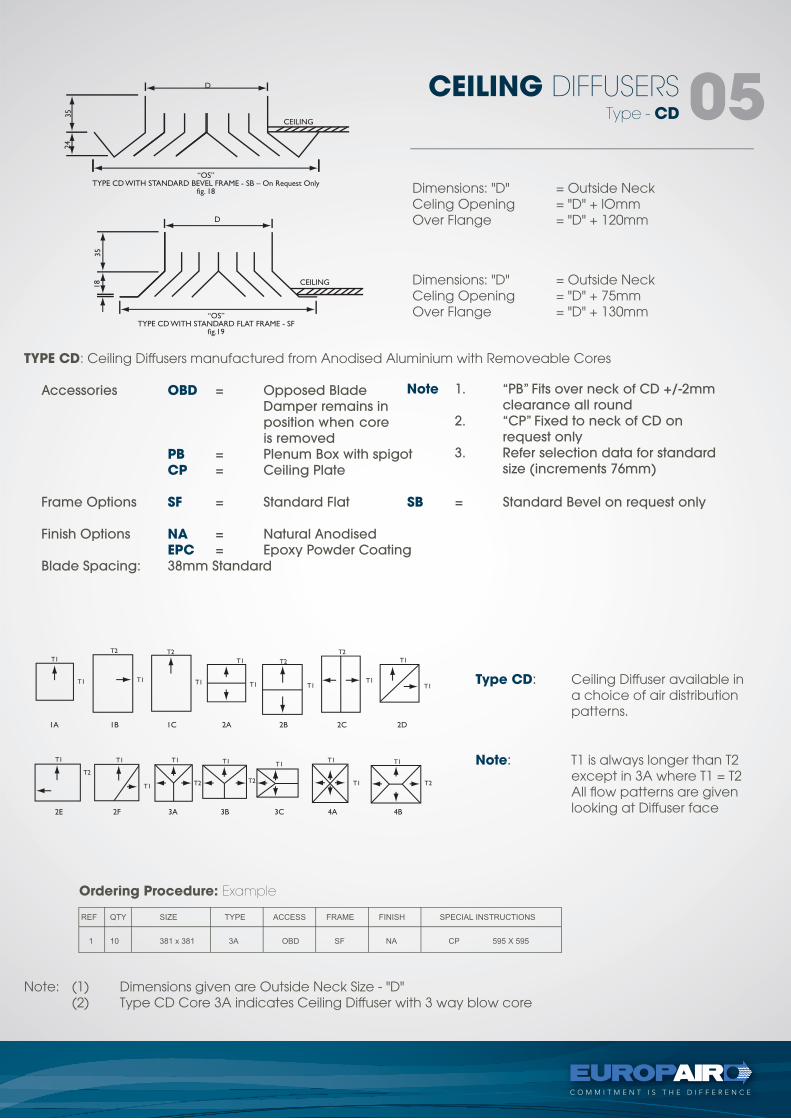
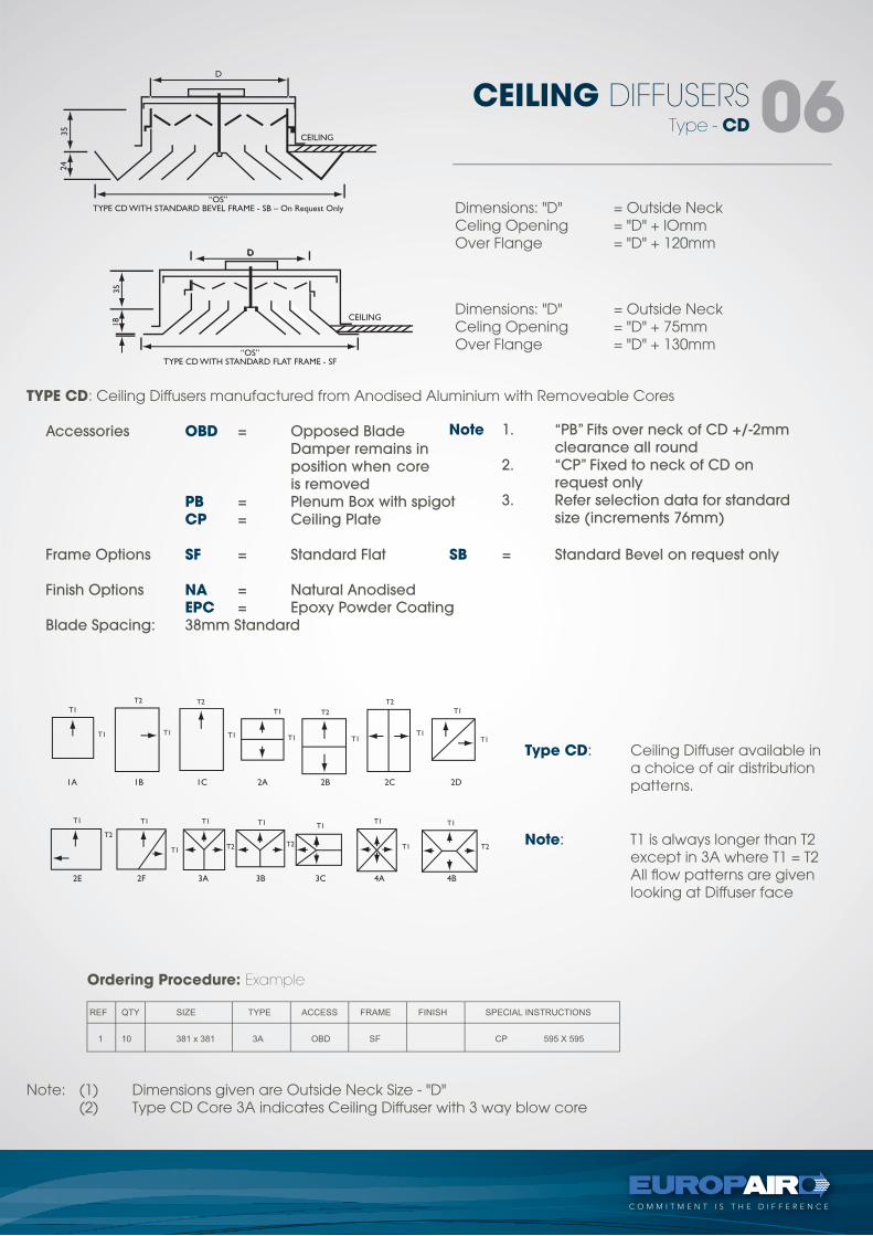
Note 1. “PB” Fits over neck of CD +/-2mm clearance all round 2. “CP” Fixed to neck of CD on request only 3. Refer selection data for standard size (increments 76mm)
Dimensions: "D" = Outside NeckCeling Opening = "D" + lOmmOver Flange = "D" + 120mm
TYPE CD: Ceiling Diffusers manufactured from Anodised Aluminium with Removeable Cores
Accessories OBD = Opposed Blade Damper remains in position when core is removed PB = Plenum Box with spigot CP = Ceiling Plate
Frame Options SF = Standard Flat SB = Standard Bevel on request only
Finish Options NA = Natural Anodised EPC = Epoxy Powder Coating Blade Spacing: 38mm Standard
Note: (1) Dimensions given are Outside Neck Size - "D" (2) Type CD Core 3A indicates Ceiling Diffuser with 3 way blow core
Type CD: Ceiling Diffuser available in a choice of air distribution patterns.
Note: T1 is always longer than T2 except in 3A where T1 = T2 All flow patterns are given looking at Diffuser face
Dimensions: "D" = Outside NeckCeling Opening = "D" + 75mmOver Flange = "D" + 130mm
Ordering Procedure: Example
Type - CD
CEILING DIFFUSERS 05
Note 1. “PB” Fits over neck of CD +/-2mm clearance all round 2. “CP” Fixed to neck of CD on request only 3. Refer selection data for standard size (increments 76mm)
Dimensions: "D" = Outside NeckCeling Opening = "D" + lOmmOver Flange = "D" + 120mm
TYPE CD: Ceiling Diffusers manufactured from Anodised Aluminium with Removeable Cores
Accessories OBD = Opposed Blade Damper remains in position when core is removed PB = Plenum Box with spigot CP = Ceiling Plate
Frame Options SF = Standard Flat SB = Standard Bevel on request only
Finish Options NA = Natural Anodised EPC = Epoxy Powder Coating Blade Spacing: 38mm Standard
Note: (1) Dimensions given are Outside Neck Size - "D" (2) Type CD Core 3A indicates Ceiling Diffuser with 3 way blow core
Type CD: Ceiling Diffuser available in a choice of air distribution patterns.
Note: T1 is always longer than T2 except in 3A where T1 = T2 All flow patterns are given looking at Diffuser face
Dimensions: "D" = Outside NeckCeling Opening = "D" + 75mmOver Flange = "D" + 130mm
Ordering Procedure: Example
Type - CD
CEILING DIFFUSERS 06
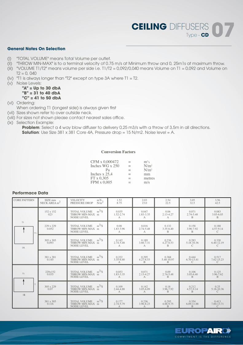
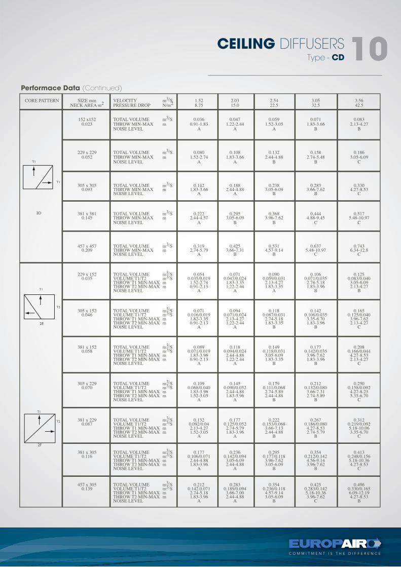
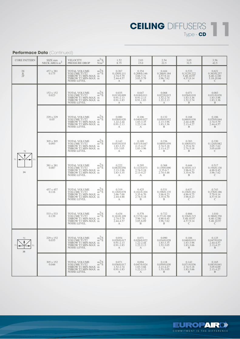
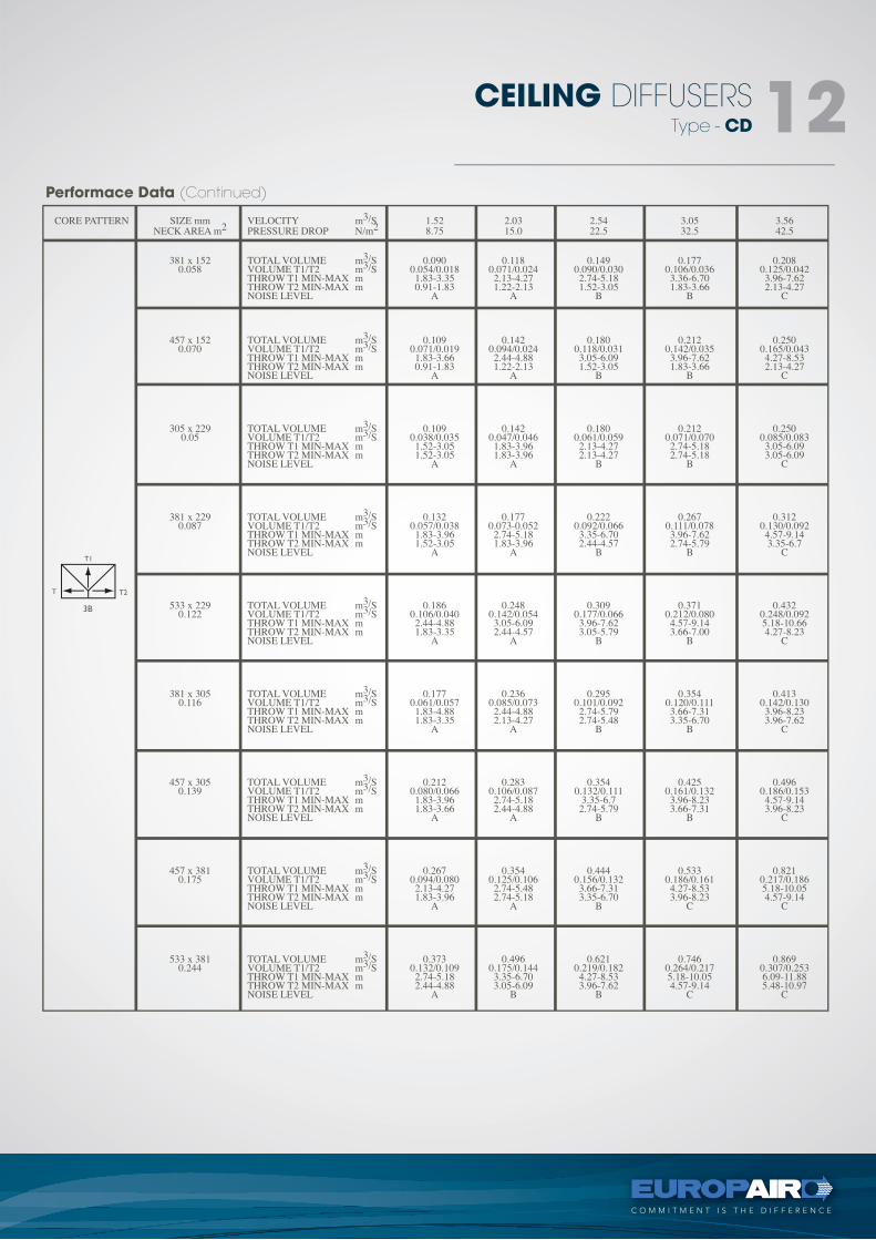
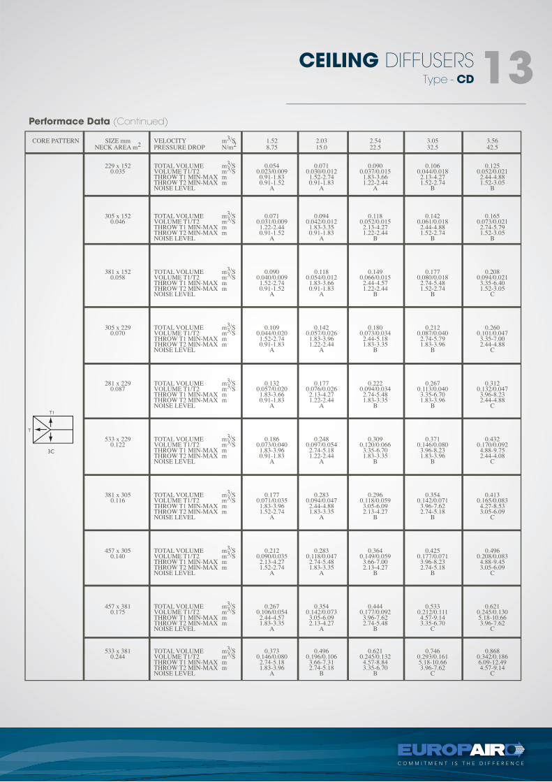
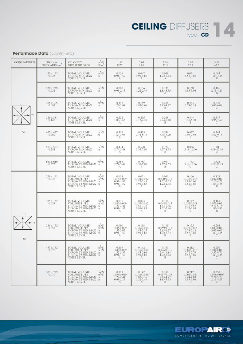
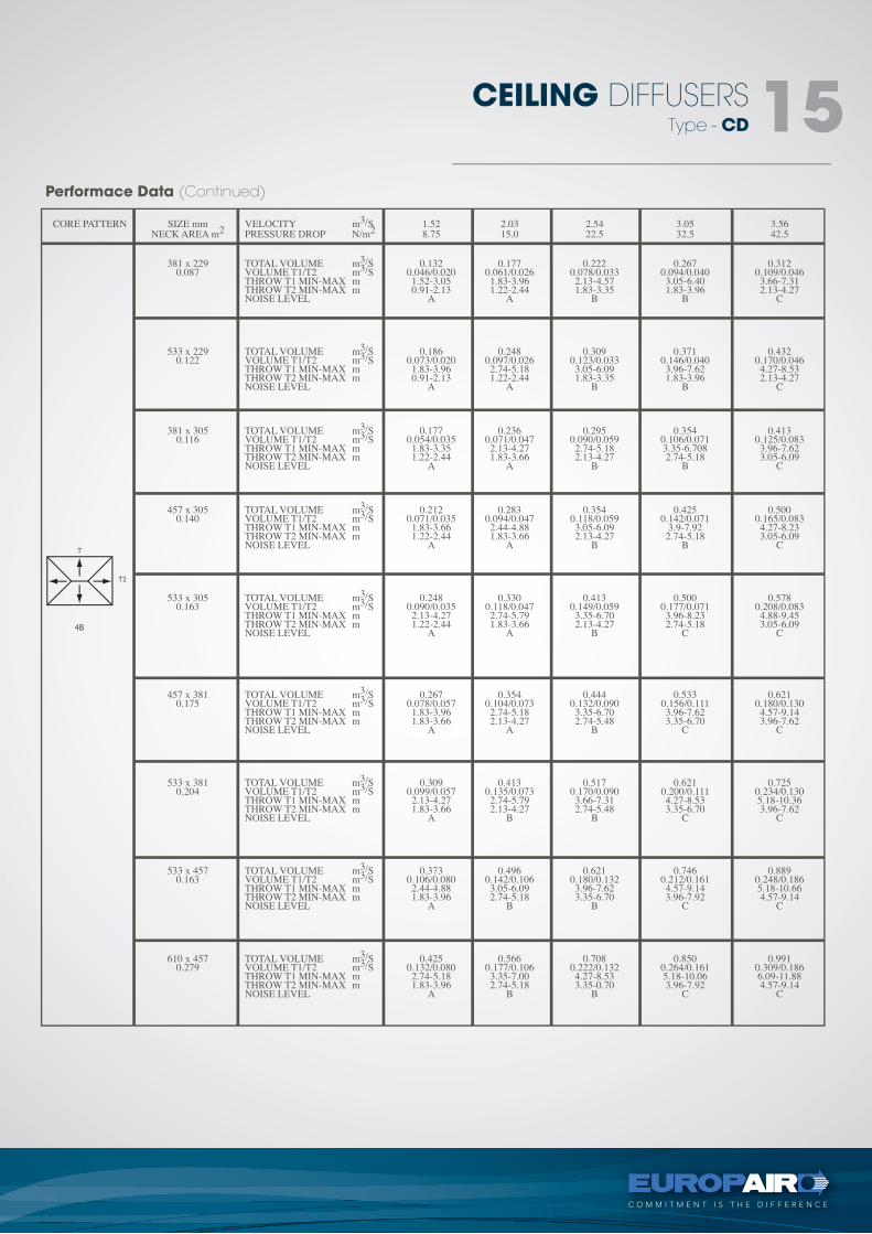
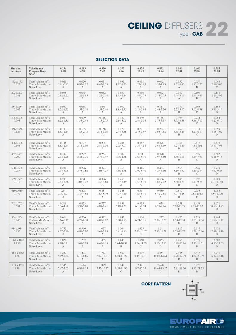
General Notes On Selection
(i) "TOTAL VOLUME" means Total Volume per outlet.(ii) "THROW MIN-MAX" is to a terminal velocity of 0.75 m/s at Minimum throw and 0, 25rn1s at maximum throw.(iii) "VOLUME T1/T2" means volume per side i.e. T1/T2 = 0,092/0,040 means Volume on T1 = 0,092 and Volume on
T2 = 0, 040(iv) "T1 is always longer than "T2" except on type 3A where T1 = T2.(v) Noise Levels: "A" = Up to 30 dbA "B" = 31 to 40 dbA "C" = 41 to 50 dbA(vi) Ordering: When ordering T1 (longest side) is always given first (vii) Sizes shown refer to over outside neck.(viii) For sizes not shown please contact nearest sales office.(ix) Selection Example: Problem: Select a 4 way blow diffuser to delivery 0,25 m3/s with a throw of 3,5m in all directions. Solution: Use Size 381 x 381 Core 4A, Pressure drop = 15 N/m2. Noise level = A.
Performace Data
Type - CD
CEILING DIFFUSERS 07
Performace Data (Continued)
Type - CD
CEILING DIFFUSERS 08
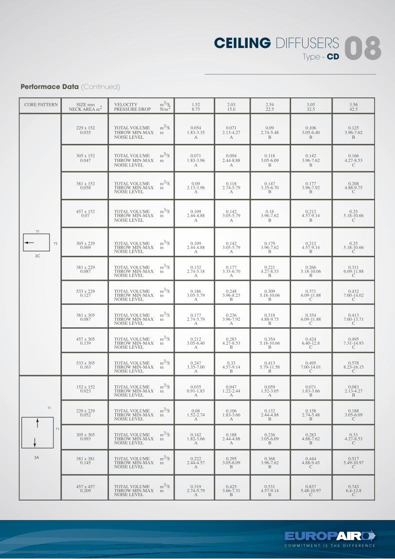
Performace Data (Continued)
Type - CD
CEILING DIFFUSERS 09
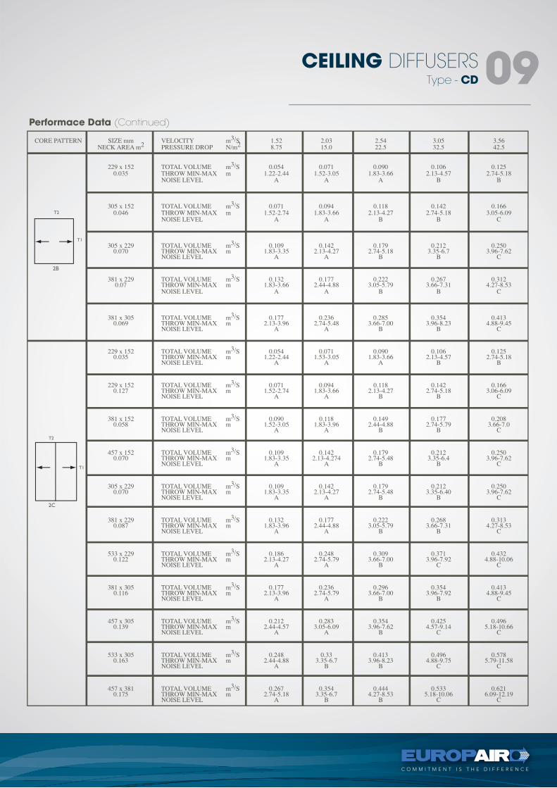
Performace Data (Continued)
Type - CD
CEILING DIFFUSERS 10
Performace Data (Continued)
Type - CD
CEILING DIFFUSERS 11
Performace Data (Continued)
Type - CD
CEILING DIFFUSERS 12
Performace Data (Continued)
Type - CD
CEILING DIFFUSERS 13
Performace Data (Continued)
Type - CD
CEILING DIFFUSERS 14
Performace Data (Continued)
Type - CD
CEILING DIFFUSERS 15
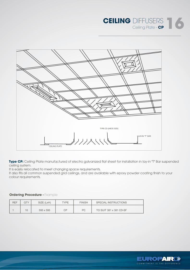
Type CP: Ceiling Plate manufactured of electro galvanized flat sheet for installation in lay-in "T" Bar suspended ceiling system.It is easily relocated to meet changing space requirements.It also fits all common suspended grid ceilings, and are available with epoxy powder coating finish to your colour requirements.
Ordering Procedure - Example
Ceiling Plate - CP
CEILING DIFFUSERS 16
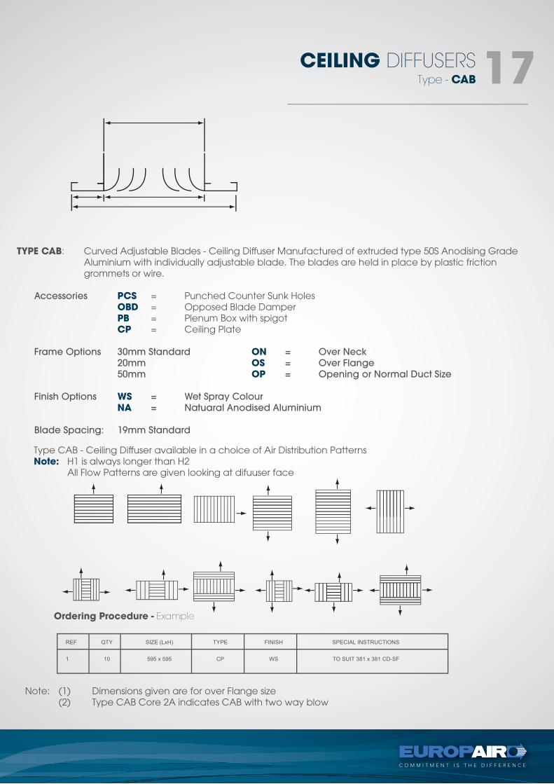
TYPE CAB: Curved Adjustable Blades - Ceiling Diffuser Manufactured of extruded type 50S Anodising Grade Aluminium with individually adjustable blade. The blades are held in place by plastic friction grommets or wire.
Accessories PCS = Punched Counter Sunk Holes OBD = Opposed Blade Damper PB = Plenum Box with spigot CP = Ceiling Plate
Frame Options 30mm Standard ON = Over Neck 20mm OS = Over Flange 50mm OP = Opening or Normal Duct Size
Finish Options WS = Wet Spray Colour NA = Natuaral Anodised Aluminium
Blade Spacing: 19mm Standard
Type CAB - Ceiling Diffuser available in a choice of Air Distribution PatternsNote: H1 is always longer than H2 All Flow Patterns are given looking at difuuser face
Ordering Procedure - Example
Note: (1) Dimensions given are for over Flange size (2) Type CAB Core 2A indicates CAB with two way blow
Type - CAB
CEILING DIFFUSERS 17
GENERAL NOTES ON SELECTIONS
A) TOTAL VOLUME MEANS TOTAL VOLUME PER OUTLET - m3/sec.
B) THROW MIN-MAX IS TO A TERMINAL VELOCITY OF 0.64 MIS MINIMUM THROW AND 0.031 MIS AT
MAXIMUM THROW.
C) VOLUME HI + H2 MEANS VOLUME PER RESPECTIVE SIDE.
D) HI IS ALWAYS LARGER THAN H2 , EXCEPT ON TYPE 3A WHERE Hl=H2.
E) NOISE (NC) LEVEL
A = 0-30 B = 31-35 C = 36-40 D = 41-45
SELECTION OF CURVED ADJUSTABLE BLADE GRILLE IS BASED UPON THROW AND M3/S REQUIREMENTS. THE THROW, M3/S AND PRESSURE DROP APPLY WHEN THE INDIVIDUAL BLADES ARE ADJUSTED IN THE MANNER ILLUSTRATED BELOW. OTHER BLADE SETTINGS WILL PROVIDE SIGNIFICANTLY DIFFERENT THROWS AND AIR DELIVERIES.
THE M3/S TABULATED IS THE VOLUME DELIVERED BY THE GRILLE. BALANCING OF CURVED BLADE IS ACCOM-PLISHED BY MEASURING FACE VELOCITY. THE MEASURED VELOCITY CAN BE CORRELATED TO TABULATED FACE VELOCITY AND M3/S WHEN THE BLADES ADJUSTMENT IS THAT AS ILLUSTRATED.
THE PERFORMANCE OF RECTANGULAR GRILLES WITH AREAS EQUAL TO SQUARE GRILLES, WILL BE THE SAME.
Type - CAB
CEILING DIFFUSERS 18
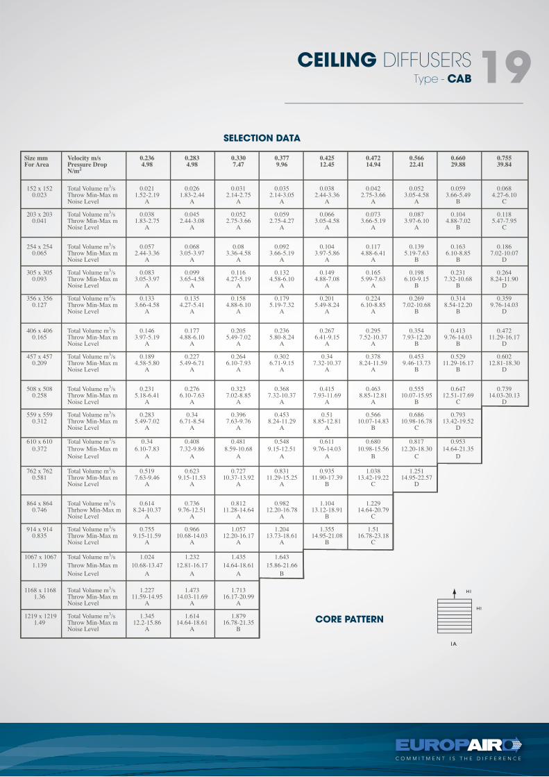
CORE PATTERN
SELECTION DATA
Type - CAB
CEILING DIFFUSERS 19
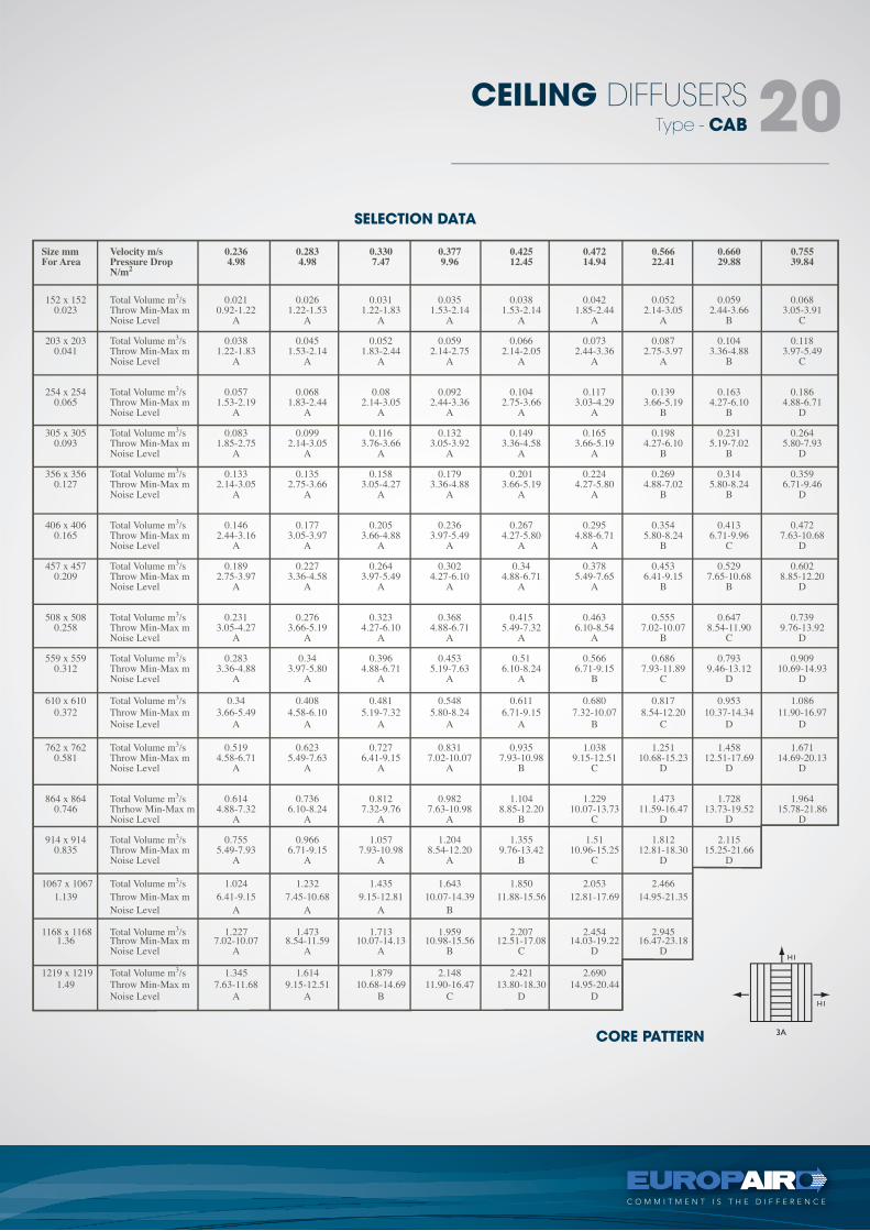
CORE PATTERN
SELECTION DATA
Type - CAB
CEILING DIFFUSERS 20
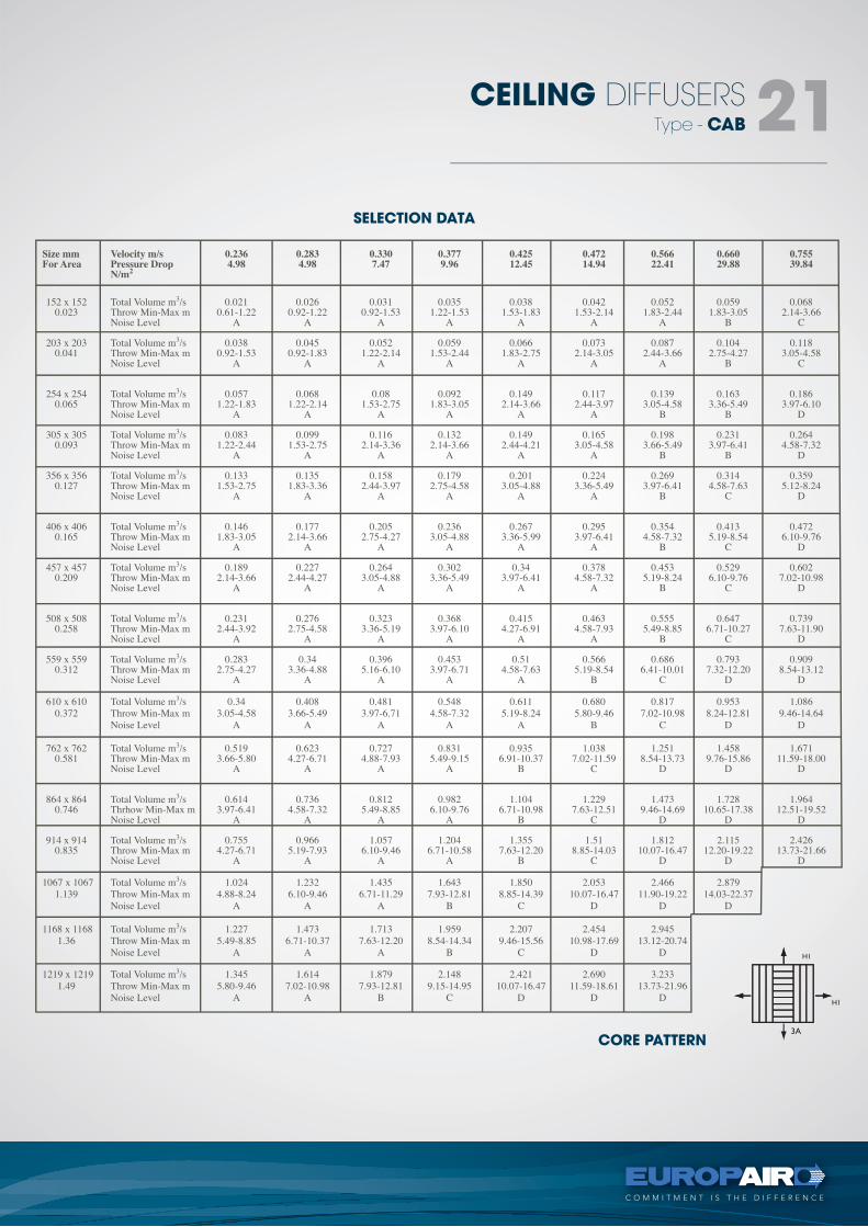
CORE PATTERN
SELECTION DATA
Type - CAB
CEILING DIFFUSERS 21
CORE PATTERN
SELECTION DATA
Type - CAB
CEILING DIFFUSERS 22
tel +27 11 974 2425
fax +27 11 974 2443
web www.europair-africa.com
email: [email protected]
Europair Africa (Pty) Ltd(a div. of First Strut)
Cnr. Grader and Vuurslag
Spartan Ext. 3
Kempton Park
Johannesburg
SUPPLY AIR GRILLEStechnical
C O M M I T M E N T I S T H E D I F F E R E N C E
types -DD, SD
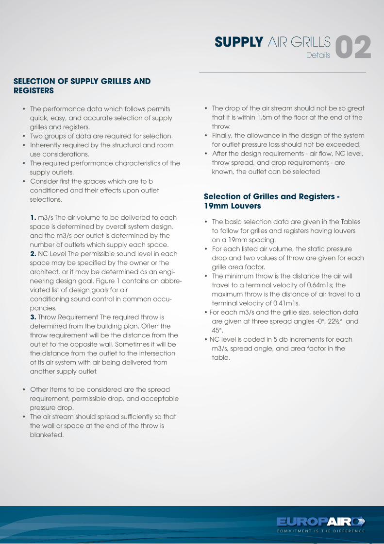
SELECTION OF SUPPLY GRILLES ANDREGISTERS
Selection of Grilles and Registers -19mm Louvers
Details
SUPPLY AIR GRILLS 02
• The performance data which follows permits quick, easy, and accurate selection of supply grilles and registers.
• Two groups of data are required for selection.• Inherently required by the structural and room
use considerations.• The required performance characteristics of the
supply outlets.• Consider first the spaces which are to b
conditioned and their effects upon outletselections.
1. m3/s The air volume to be delivered to each space is determined by overall system design, and the m3/s per outlet is determined by the number of outlets which supply each space.
2. NC Level The permissible sound level in each space may be specified by the owner or the architect, or it may be determined as an engi-neering design goal. Figure 1 contains an abbre-viated list of design goals for airconditioning sound control in common occu-pancies.
3. Throw Requirement The required throw is determined from the building plan. Often the throw requirement will be the distance from the outlet to the opposite wall. Sometimes it will be the distance from the outlet to the intersection of its air system with air being delivered from another supply outlet.
• Other items to be considered are the spread requirement, permissible drop, and acceptable pressure drop.
• The air stream should spread sufficiently so that the wall or space at the end of the throw is blanketed.
• The drop of the air stream should not be so great that it is within 1.5m of the floor at the end of the throw.
• Finally, the allowance in the design of the system for outlet pressure loss should not be exceeded.
• After the design requirements - air flow, NC level, throw spread, and drop requirements - are known, the outlet can be selected
• The basic selection data are given in the Tables to follow for grilles and registers having louvers on a 19mm spacing.
• For each listed air volume, the static pressure drop and two values of throw are given for each grille area factor.
• The minimum throw is the distance the air will travel to a terminal velocity of 0.64m1s; the maximum throw is the distance of air travel to a terminal velocity of 0.41m1s.
• For each m3/s and the grille size, selection data are given at three spread angles -0°, 22½° and 45°.
• NC level is coded in 5 db increments for each m3/s, spread angle, and area factor in the table.
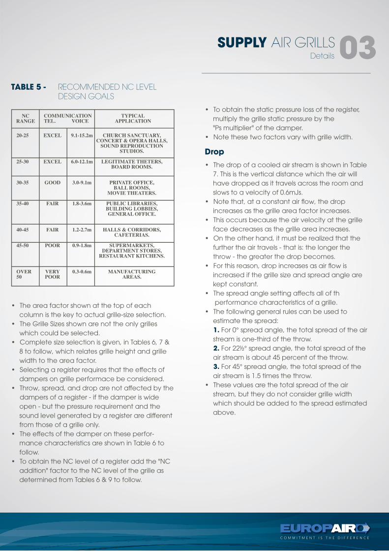
TABLE 5 - RECOMMENDED NC LEVEL DESIGN GOALS
Details
SUPPLY AIR GRILLS 03
• The area factor shown at the top of each column is the key to actual grille-size selection.
• The Grille Sizes shown are not the only grilles which could be selected.
• Complete size selection is given, in Tables 6, 7 & 8 to follow, which relates grille height and grille width to the area factor.
• Selecting a register requires that the effects of dampers on grille performace be considered.
• Throw, spread, and drop are not affected by the dampers of a register - if the damper is wide
open - but the pressure requirement and the sound level generated by a register are different from those of a grille only.
• The effects of the damper on these perfor-mance characteristics are shown in Table 6 to follow.
• To obtain the NC level of a register add the "NC addition" factor to the NC level of the grille as determined from Tables 6 & 9 to follow.
• To obtain the static pressure loss of the register, multiply the grille static pressure by the"Ps multiplier" of the damper.
• Note these two factors vary with grille width.
• The drop of a cooled air stream is shown in Table 7. This is the vertical distance which the air will have dropped as it travels across the room and slows to a velocity of 0.6mJs.
• Note that, at a constant air flow, the drop increases as the grille area factor increases.
• This occurs because the air velocity at the grille face decreases as the grille area increases.
• On the other hand, it must be realized that the further the air travels - that is: the longer the throw - the greater the drop becomes.
• For this reason, drop increases as air flow is increased if the grille size and spread angle are kept constant.
• The spread angle setting affects all of th performance characteristics of a grille.
• The following general rules can be used to estimate the spread:
1. For 0° spread angle, the total spread of the air stream is one-third of the throw.
2. For 22½° spread angle, the total spread of the air stream is about 45 percent of the throw.
3. For 45° spread angle, the total spread of the air stream is 1.5 times the throw.
• These values are the total spread of the air stream, but they do not consider grille width which should be added to the spread estimated above.
Drop
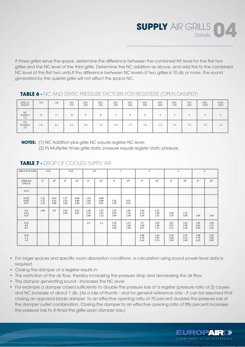
TABLE 6 - NC AND STATIC PRESSURE FACTORS FOR REGISTERS (OPEN DAMPER)
TABLE 7 - DROP OF COOLED SUPPLY AIR
Details
SUPPLY AIR GRILLS 04
If three grilles serve the space, determine the difference between the combined NY level for the fIrst two grilles and the NC level of the third grille. Determine the NC addition as above, and add this to the combined NC level of the first two units.If the difference between NC levels of two grilles is 10 db or more, the sound generated by the quieter grille will not affect the space NC.
• For larger spaces and specific room absorption conditions, a calculation using sound power level data is required.
• Closing the damper of a register results in:• The restriction of the air flow, thereby increasing the pressure drop and decreasing the air flow.• The damper generating sound - increases the NC level.• For example a damper closed sufficiently to double the pressure loss of a register (pressure ratio of 2) causes
and NC increase of about 7 db. (As a rule of thumb - and for general reference only - it can be assumed that closing an opposed blade damper to an effective opening ratio of 70 percent doubles the pressure loss of the damper outlet combination. Closing the damper to an effective opening ratio of fifty percent increases the pressure loss to 4-times the grille-open damper loss.)
NOTES: (1) NC Addition plus grille NC equals register NC level. (2) Ps Multiplier times grille static pressure equals register static pressure.
Combining Sound Sources
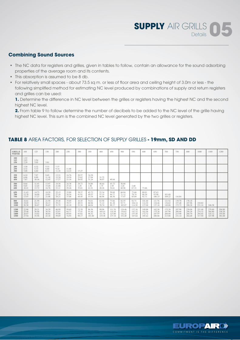
TABLE 8 AREA FACTORS, FOR SELECTION OF SUPPLY GRILLES - 19mm, SD AND DD
Details
SUPPLY AIR GRILLS 05
• The NC data for registers and grilles, given in tables to follow, contain an allowance for the sound adsorbing properties of the average room and its contents.
• This absorption is assumed to be 8 db.• For relatively small spaces - about 73.5 sq m. or less of floor area and ceiling height of 3.0m or less - the
following simplified method for estimating NC level produced by combinations of supply and return registers and grilles can be used:
1. Determine the difference in NC level between the grilles or registers having the highest NC and the second highest NC level.
2. From table 9 to follow determine the number of decibels to be added to the NC level of the grille having highest NC level. This sum is the combined NC level generated by the two grilles or registers.
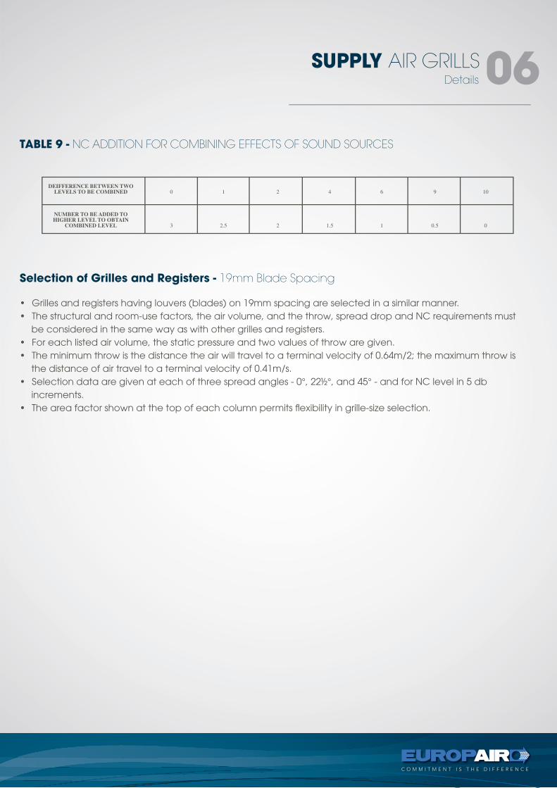
TABLE 9 - NC ADDITION FOR COMBINING EFFECTS OF SOUND SOURCES
Selection of Grilles and Registers - 19mm Blade Spacing
Details
SUPPLY AIR GRILLS 06
• Grilles and registers having louvers (blades) on 19mm spacing are selected in a similar manner.• The structural and room-use factors, the air volume, and the throw, spread drop and NC requirements must
be considered in the same way as with other grilles and registers.• For each listed air volume, the static pressure and two values of throw are given.• The minimum throw is the distance the air will travel to a terminal velocity of 0.64m/2; the maximum throw is
the distance of air travel to a terminal velocity of 0.41m/s.• Selection data are given at each of three spread angles - 0°, 22½°, and 45° - and for NC level in 5 db
increments.• The area factor shown at the top of each column permits flexibility in grille-size selection.
Type - DD
SUPPLY AIR GRILLS 07
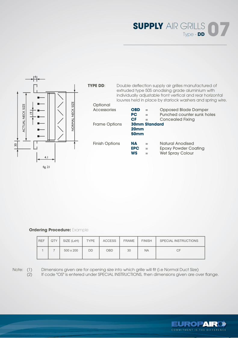
TYPE DD: Double deflection supply air grilles manufactured of extruded type 50S anodising grade aluminium with individually adjustable front vertical and rear horizontal louvres held in place by starlock washers and spring wire. Optional
Accessories OBD = Opposed Blade Damper
PC = Punched counter sunk holes
CF = Concealed Fixing
Frame Options 30mm Standard 20mm 50mm
Finish Options NA = Natural Anodised
EPC = Epoxy Powder Coating
WS = Wet Spray Colour
Note: (1) Dimensions given are for opening size into which grille will fit (i.e Normal Duct Size) (2) If code "OS" is entered under SPECIAL INSTRUCTIONS, then dimensions given are over flange.
Ordering Procedure: Example
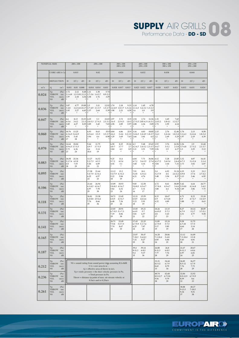
SUPPLY AIR GRILLS 08Performance Data - DD - SD
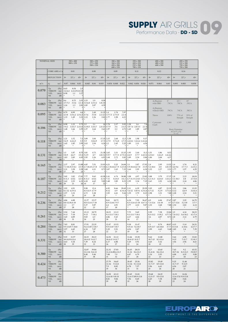
Performance Data - DD - SD
SUPPLY AIR GRILLS 09
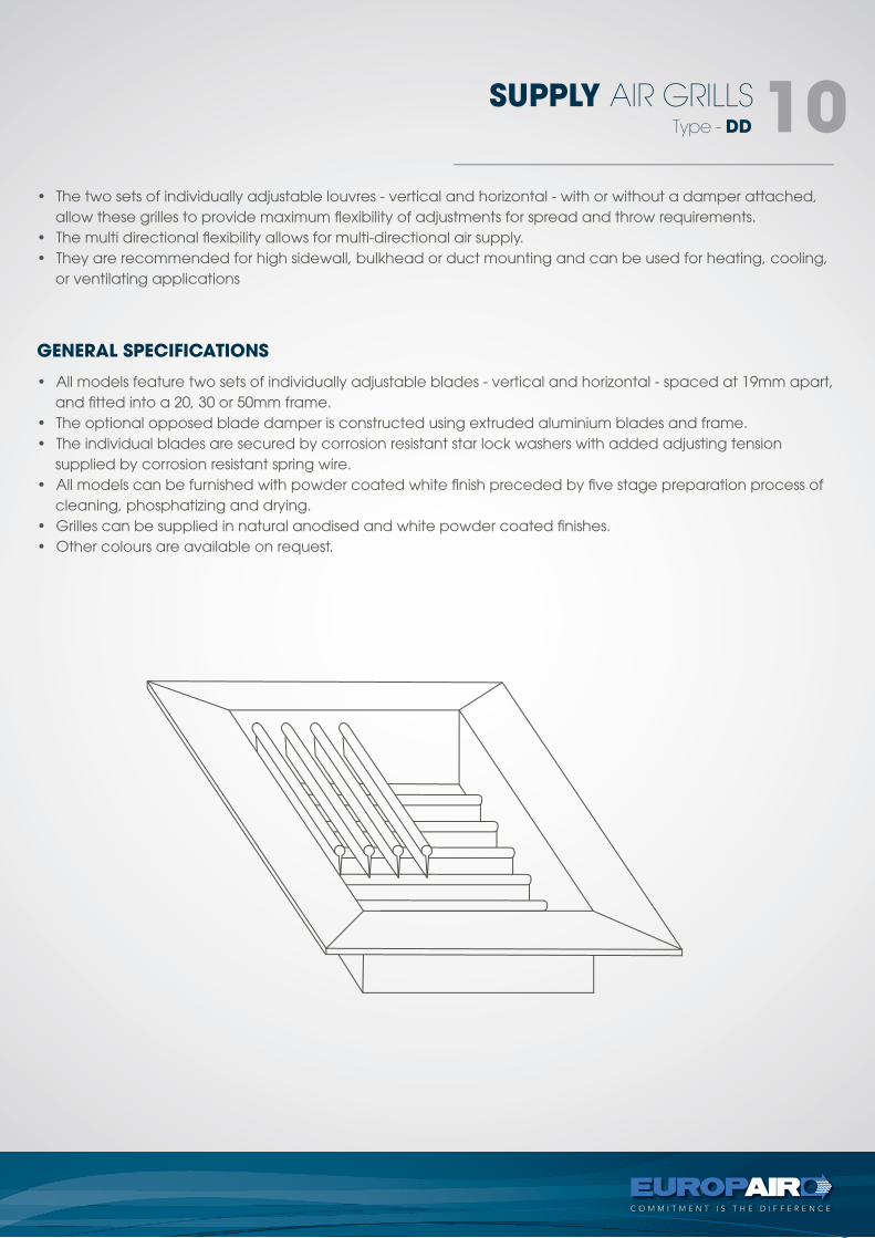
TABLE 5 - RECOMMENDED NC LEVELDESIGN GOALS
Details
SUPPLY AIR GRILLS 10SUPPLY AIR GRILLS 10• The two sets of individually adjustable louvres - vertical and horizontal - with or without a damper attached,
allow these grilles to provide maximum flexibility of adjustments for spread and throw requirements.• The multi directional flexibility allows for multi-directional air supply.• They are recommended for high sidewall, bulkhead or duct mounting and can be used for heating, cooling,
or ventilating applications
• All models feature two sets of individually adjustable blades - vertical and horizontal - spaced at 19mm apart, and fitted into a 20, 30 or 50mm frame.
• The optional opposed blade damper is constructed using extruded aluminium blades and frame.• The individual blades are secured by corrosion resistant star lock washers with added adjusting tension
supplied by corrosion resistant spring wire.• All models can be furnished with powder coated white finish preceded by five stage preparation process of
cleaning, phosphatizing and drying.• Grilles can be supplied in natural anodised and white powder coated finishes.• Other colours are available on request.
GENERAL SPECIFICATIONS
Type - DD
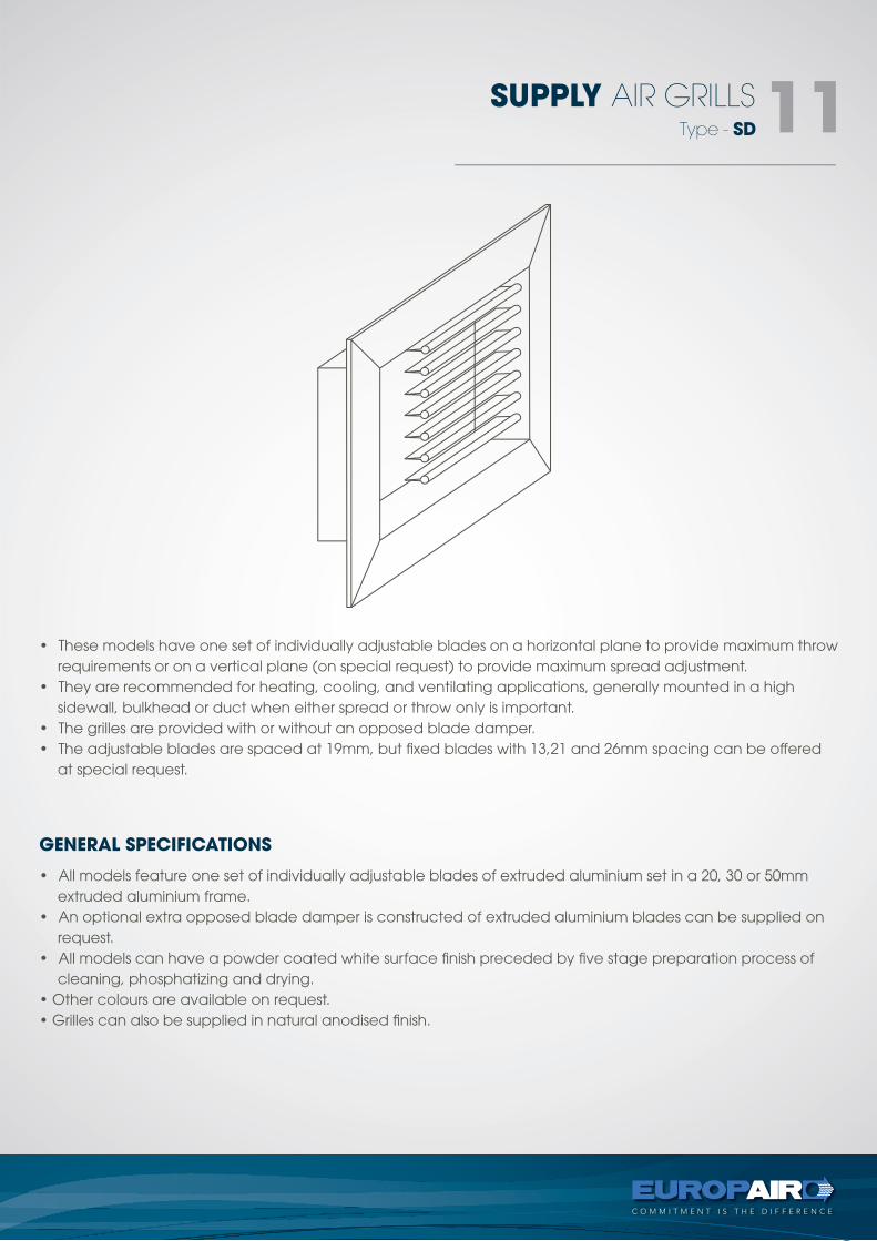
• These models have one set of individually adjustable blades on a horizontal plane to provide maximum throw requirements or on a vertical plane (on special request) to provide maximum spread adjustment.
• They are recommended for heating, cooling, and ventilating applications, generally mounted in a high sidewall, bulkhead or duct when either spread or throw only is important.
• The grilles are provided with or without an opposed blade damper.• The adjustable blades are spaced at 19mm, but fixed blades with 13,21 and 26mm spacing can be offered
at special request.
• All models feature one set of individually adjustable blades of extruded aluminium set in a 20, 30 or 50mm extruded aluminium frame.
• An optional extra opposed blade damper is constructed of extruded aluminium blades can be supplied on request.
• All models can have a powder coated white surface finish preceded by five stage preparation process of cleaning, phosphatizing and drying.
• Other colours are available on request.• Grilles can also be supplied in natural anodised finish.
GENERAL SPECIFICATIONS
SUPPLY AIR GRILLS 11Type - SD
Details
SUPPLY AIR GRILLS 12
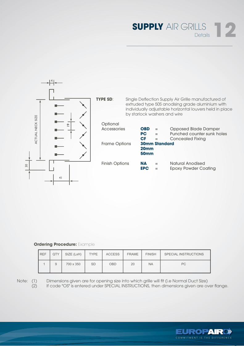
TYPE SD: Single Deflection Supply Air Grille manufactured of extruded type 50S anodising grade aluminium with
individually adjustable horizontal louvers held in place by starlock washers and wire
Optional
Accessories OBD = Opposed Blade Damper
PC = Punched counter sunk holes
CF = Concealed Fixing
Frame Options 30mm Standard 20mm 50mm
Finish Options NA = Natural Anodised
EPC = Epoxy Powder Coating
Note: (1) Dimensions given are for opening size into which grille will fit (i.e Normal Duct Size) (2) If code "OS" is entered under SPECIAL INSTRUCTIONS, then dimensions given are over flange.
Ordering Procedure: Example
tel +27 11 974 2425
fax +27 11 974 2443
web www.europair-africa.com
email: [email protected]
Europair Africa (Pty) Ltd(a div. of First Strut)
Cnr. Grader and Vuurslag
Spartan Ext. 3
Kempton Park
Johannesburg
RETURN AIR GRILLEStechnical
C O M M I T M E N T I S T H E D I F F E R E N C E
types -RA, RARB, RAFF, TG, EC
RETURN AIR GRILLS 02
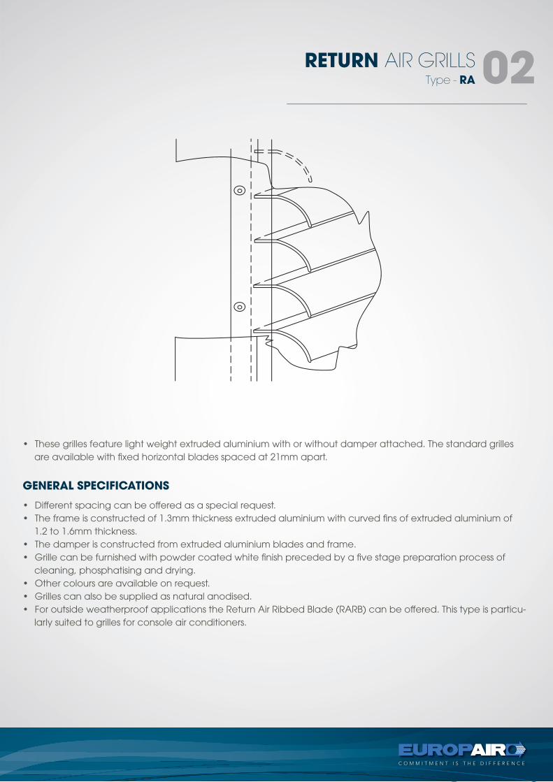
• These grilles feature light weight extruded aluminium with or without damper attached. The standard grilles are available with fixed horizontal blades spaced at 21mm apart.
• Different spacing can be offered as a special request.• The frame is constructed of 1.3mm thickness extruded aluminium with curved fins of extruded aluminium of
1.2 to 1.6mm thickness.• The damper is constructed from extruded aluminium blades and frame.• Grille can be furnished with powder coated white finish preceded by a five stage preparation process of
cleaning, phosphatising and drying.• Other colours are available on request.• Grilles can also be supplied as natural anodised.• For outside weatherproof applications the Return Air Ribbed Blade (RARB) can be offered. This type is particu-
larly suited to grilles for console air conditioners.
GENERAL SPECIFICATIONS
Type - RA
Details
RETURN AIR GRILLS 03
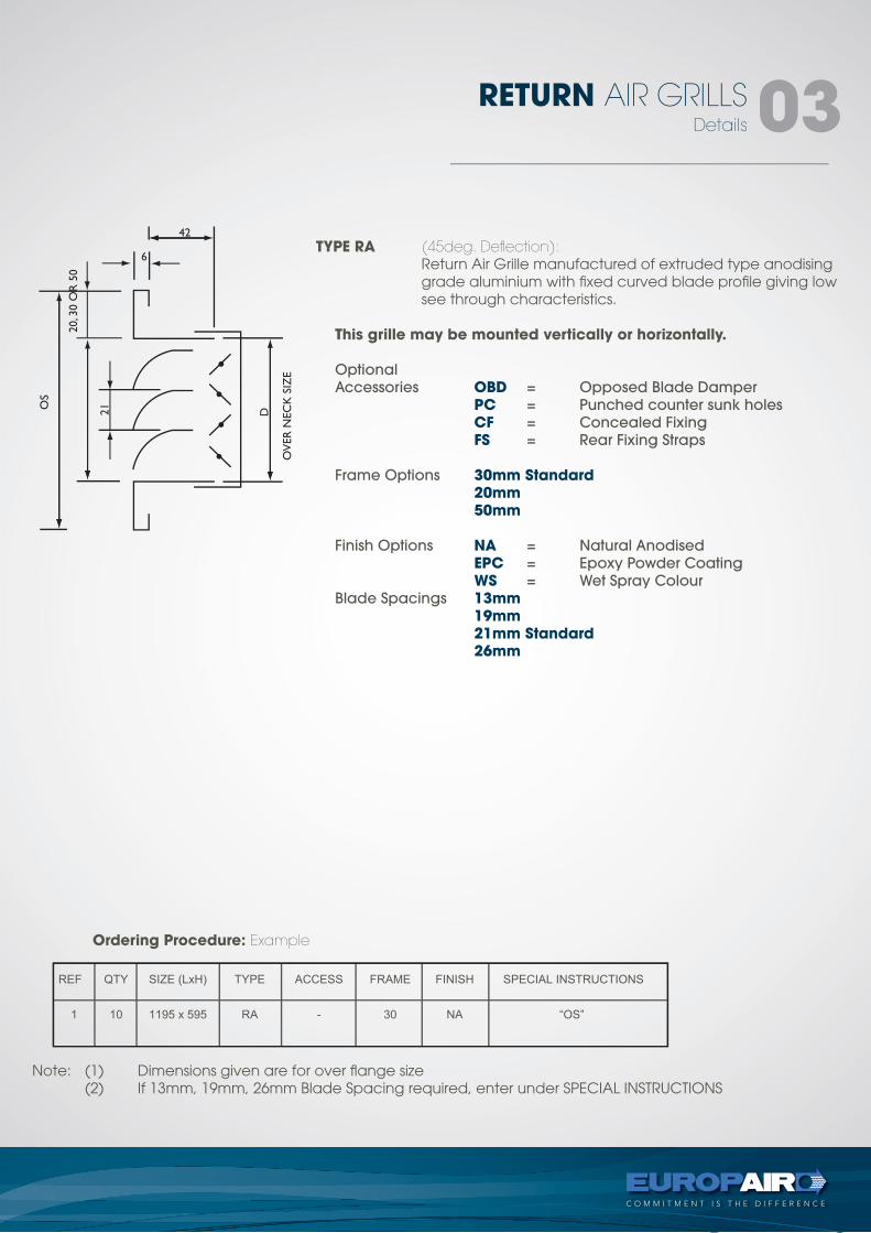
TYPE RA (45deg. Deflection): Return Air Grille manufactured of extruded type anodising
grade aluminium with fixed curved blade profile giving low see through characteristics.
This grille may be mounted vertically or horizontally.
Optional
Accessories OBD = Opposed Blade Damper
PC = Punched counter sunk holes
CF = Concealed Fixing
FS = Rear Fixing Straps
Frame Options 30mm Standard 20mm 50mm
Finish Options NA = Natural Anodised
EPC = Epoxy Powder Coating
WS = Wet Spray Colour
Blade Spacings 13mm 19mm 21mm Standard 26mm
Note: (1) Dimensions given are for over flange size (2) If 13mm, 19mm, 26mm Blade Spacing required, enter under SPECIAL INSTRUCTIONS
Ordering Procedure: Example
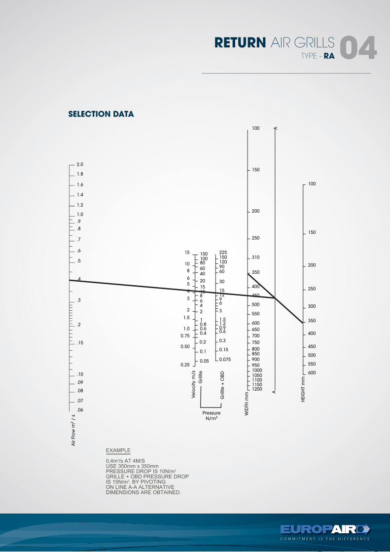
SELECTION DATA
TYPE - RA
RETURN AIR GRILLS 04
15010080
6040
20
1510864
2
10.80.60.4
0.2
0.1
0.05
15
10
8
6
5
4
3
2
1.5
1.0
0.75
0.50
0.25
1.8
2.0
1.6
1.4
1.2
1.0
.9
.8
.7
.6
.5
.4
.3
.2
.15
.10
.09
.08
.07
.06
100
150
200
250
300
350
400
450
500
550
600
100
150
200
250
310
350
400
450
500
550
600
650
700
750
800850
900
95010001050110011501200
2251501209060
30
151296
3
1.51.20.90.6
0.3
0.15
0.075
AA
HEIG
HT
mm
WID
TH m
m
Grilll
e +
OBD
Grilll
e
Ve
loc
ity m
/s
Air F
low
m3
/ s
Pressure
N/m2
TYPE - RARB
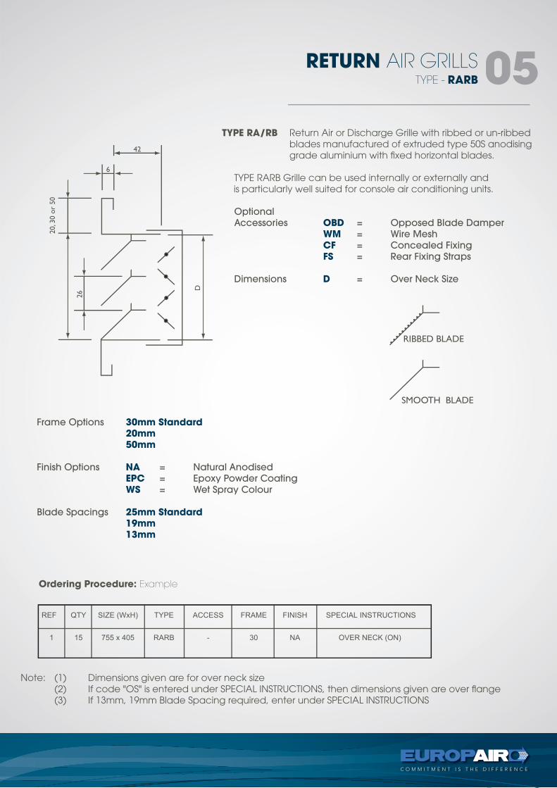
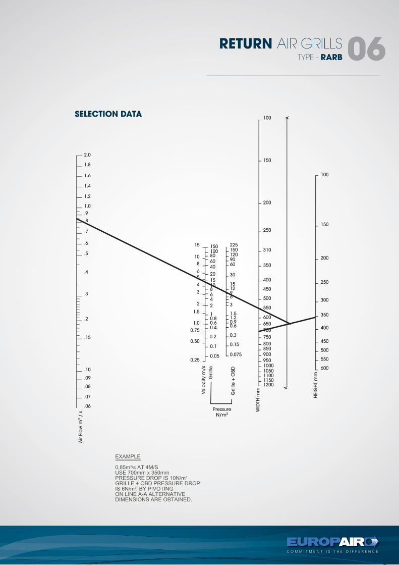
RETURN AIR GRILLS 05TYPE RA/RB Return Air or Discharge Grille with ribbed or un-ribbed
blades manufactured of extruded type 50S anodising grade aluminium with fixed horizontal blades.
TYPE RARB Grille can be used internally or externally andis particularly well suited for console air conditioning units.
Optional
Accessories OBD = Opposed Blade Damper
WM = Wire Mesh
CF = Concealed Fixing
FS = Rear Fixing Straps
Dimensions D = Over Neck Size
Frame Options 30mm Standard 20mm 50mm
Finish Options NA = Natural Anodised
EPC = Epoxy Powder Coating
WS = Wet Spray Colour
Blade Spacings 25mm Standard 19mm 13mm
Note: (1) Dimensions given are for over neck size (2) If code "OS" is entered under SPECIAL INSTRUCTIONS, then dimensions given are over flange (3) If 13mm, 19mm Blade Spacing required, enter under SPECIAL INSTRUCTIONS
Ordering Procedure: Example
FIXED BLADE CEILING DIFFUSER - CD
Details
RETURN AIR GRILLS 06TYPE - RARB
RETURN AIR GRILLS 06
15010080
6040
20
1510864
2
10.80.60.4
0.2
0.1
0.05
15
10
8
6
5
4
3
2
1.5
1.0
0.75
0.50
0.25
1.8
2.0
1.6
1.4
1.2
1.0
.9
.8
.7
.6
.5
.4
.3
.2
.15
.10
.09
.08
.07
.06
100
150
200
250
300
350
400
450
500
550
600
100
150
200
250
310
350
400
450
500
550
600
650
700
750
800850
900
95010001050110011501200
2251501209060
30
151296
3
1.51.20.90.6
0.3
0.15
0.075
AA
HEIG
HT
mm
WID
TH m
m
Grilll
e +
OBD
Grilll
e
Ve
loc
ity m
/s
Air F
low
m3
/ s
Pressure
N/m2
SELECTION DATA
FIXED BLADE CEILING DIFFUSER - CD
Details
RETURN AIR GRILLS 06
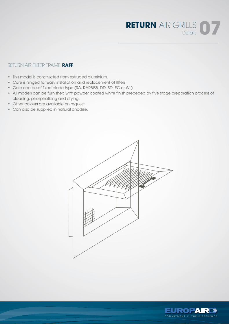
RETURN AIR FILTER FRAME RAFF
Details
RETURN AIR GRILLS 07
• This model is constructed from extruded aluminium.• Core is hinged for easy installation and replacement of ftlters.• Core can be of fixed blade type (RA, RARBISB, DD, SD, EC or WL)• All models can be furnished with powder coated white fInish preceded by fIve stage preparation process of
cleaning, phosphatizing and drying.• Other colours are available on request.• Can also be supplied in natural anodize.
TYPE - RAFF
RETURN AIR GRILLS 08
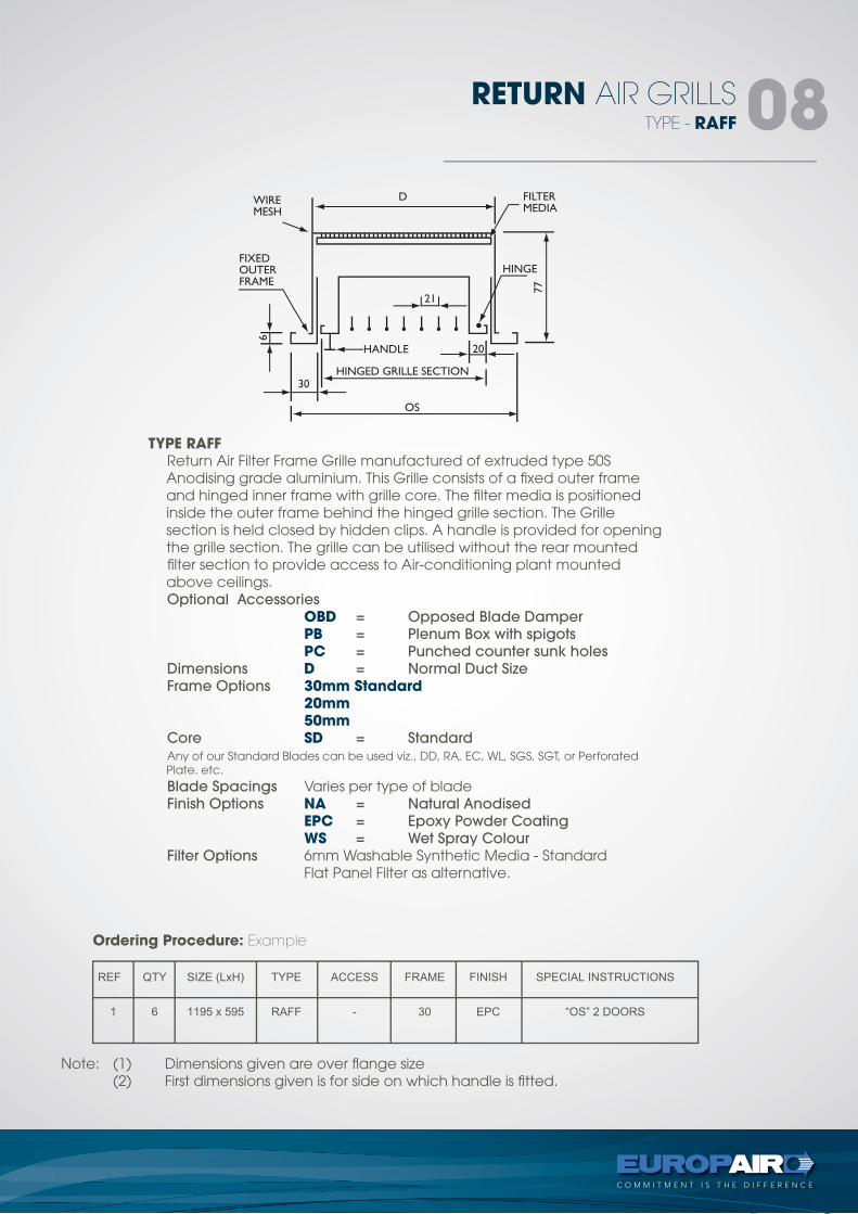
TYPE RAFF Return Air Filter Frame Grille manufactured of extruded type 50S
Anodising grade aluminium. This Grille consists of a fixed outer frame and hinged inner frame with grille core. The filter media is positioned inside the outer frame behind the hinged grille section. The Grille section is held closed by hidden clips. A handle is provided for opening the grille section. The grille can be utilised without the rear mounted filter section to provide access to Air-conditioning plant mounted above ceilings.
Optional Accessories
OBD = Opposed Blade Damper
PB = Plenum Box with spigots
PC = Punched counter sunk holes
Dimensions D = Normal Duct Size
Frame Options 30mm Standard 20mm 50mm Core SD = Standard
Any of our Standard Blades can be used viz., DD, RA, EC, WL, SGS, SGT, or Perforated Plate. etc.
Blade Spacings Varies per type of blade Finish Options NA = Natural Anodised
EPC = Epoxy Powder Coating
WS = Wet Spray Colour
Filter Options 6mm Washable Synthetic Media - Standard Flat Panel Filter as alternative.
Ordering Procedure: Example
Note: (1) Dimensions given are over flange size (2) First dimensions given is for side on which handle is fitted.
FIXED BLADE CEILING DIFFUSER - CD
Details
RETURN AIR GRILLS 06
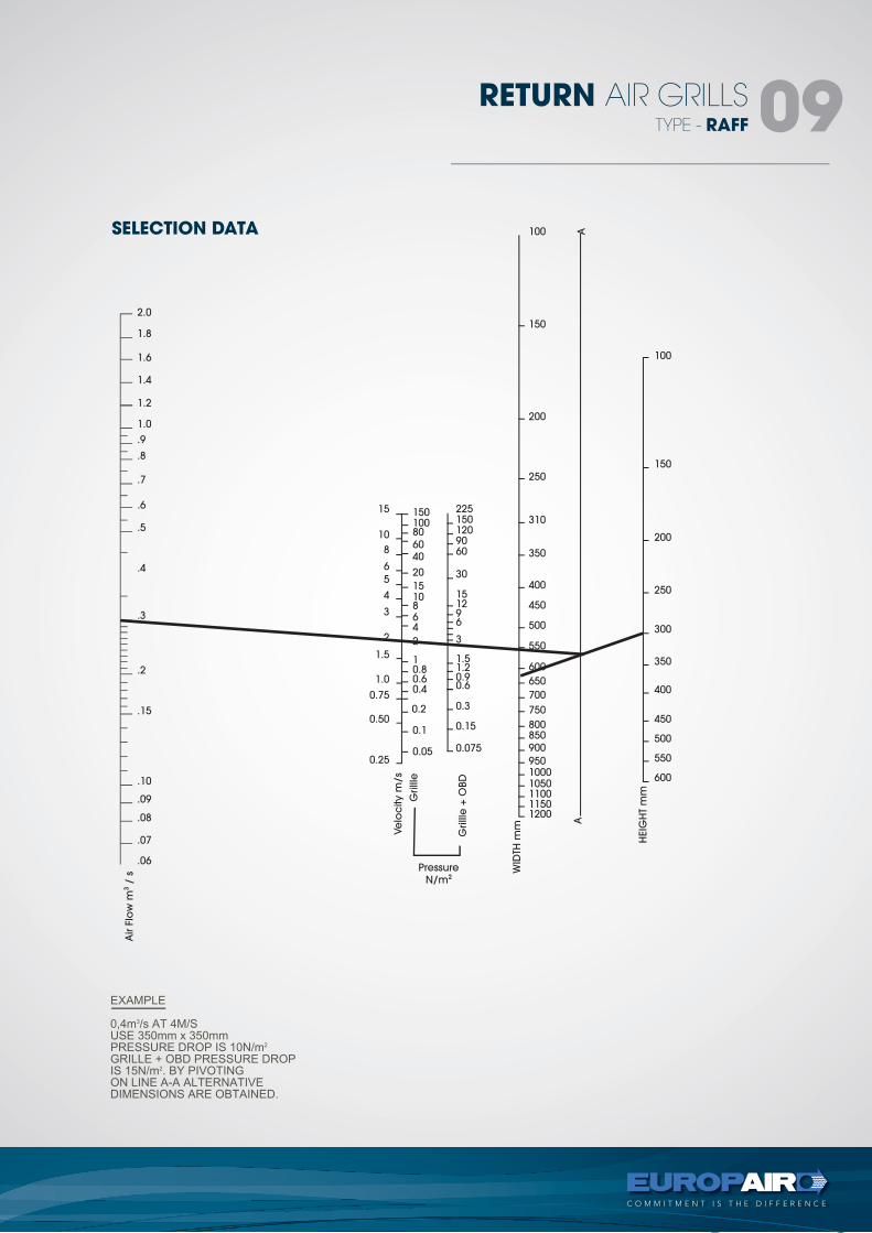
SELECTION DATA
TYPE - RAFF
RETURN AIR GRILLS 09
15010080
6040
20
1510864
2
10.80.60.4
0.2
0.1
0.05
15
10
8
6
5
4
3
2
1.5
1.0
0.75
0.50
0.25
1.8
2.0
1.6
1.4
1.2
1.0
.9
.8
.7
.6
.5
.4
.3
.2
.15
.10
.09
.08
.07
.06
100
150
200
250
300
350
400
450
500
550
600
100
150
200
250
310
350
400
450
500
550
600
650
700
750
800850
900
95010001050110011501200
2251501209060
30
151296
3
1.51.20.90.6
0.3
0.15
0.075
AA
HEIG
HT
mm
WID
TH m
m
Grilll
e +
OBD
Grilll
e
Ve
loc
ity m
/s
Air F
low
m3
/ s
Pressure
N/m2
FIXED BLADE CEILING DIFFUSER - CD
Details
RETURN AIR GRILLS 06Details
TRANSFER RETURN AIR GRILLS10
Ordering Procedure: Example
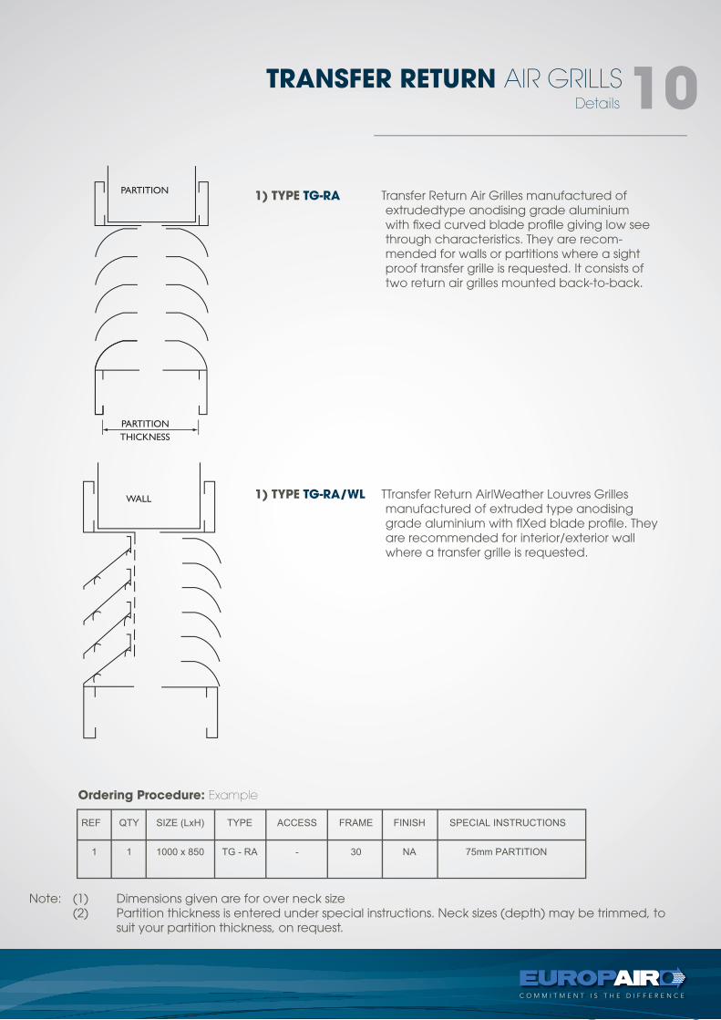
1) TYPE TG-RA Transfer Return Air Grilles manufactured of extrudedtype anodising grade aluminium with fixed curved blade profile giving low see through characteristics. They are recom-mended for walls or partitions where a sight proof transfer grille is requested. It consists of two return air grilles mounted back-to-back.
1) TYPE TG-RA/WL TTransfer Return AirlWeather Louvres Grilles manufactured of extruded type anodising grade aluminium with fIXed blade profile. They are recommended for interior/exterior wall where a transfer grille is requested.
Note: (1) Dimensions given are for over neck size (2) Partition thickness is entered under special instructions. Neck sizes (depth) may be trimmed, to
suit your partition thickness, on request.
tel +27 11 974 2425
fax +27 11 974 2443
web www.europair-africa.com
email: [email protected]
Europair Africa (Pty) Ltd(a div. of First Strut)
Cnr. Grader and Vuurslag
Spartan Ext. 3
Kempton Park
Johannesburg
STRIP GRILLEStechnical
types -SGT, SGS, FLG
C O M M I T M E N T I S T H E D I F F E R E N C E
Type - SGT
STRIP GRILLS 02
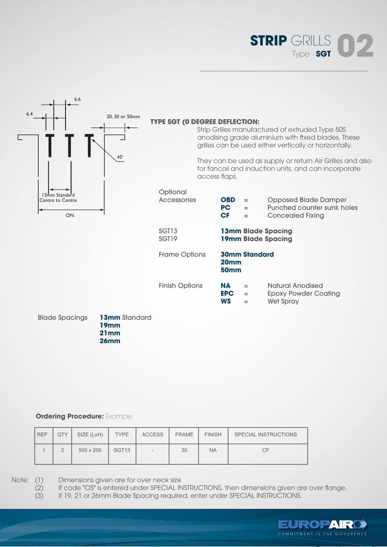
TYPE SGT (0 DEGREE DEFLECTION: Strip Grilles manufactured of extruded Type 50S
anodising grade aluminium with ftxed blades. These grilles can be used either vertically or horizontally.
They can be used as supply or return Air Grilles and also for fancoil and induction units, and can incorporate access flaps.
Optional
Accessories OBD = Opposed Blade Damper
PC = Punched counter sunk holes
CF = Concealed Fixing
SGT13 13mm Blade Spacing SGT19 19mm Blade Spacing
Frame Options 30mm Standard 20mm 50mm
Finish Options NA = Natural Anodised
EPC = Epoxy Powder Coating
WS = Wet Spray
Blade Spacings 13mm Standard
19mm 21mm 26mm
Ordering Procedure: Example
Note: (1) Dimensions given are for over neck size (2) If code "OS" is entered under SPECIAL INSTRUCTIONS, then dimensions given are over flange. (3) If 19, 21 or 26mm Blade Spacing required, enter under SPECIAL INSTRUCTIONS.
Type - SGT
SELECTION DATA
STRIP GRILLS 03
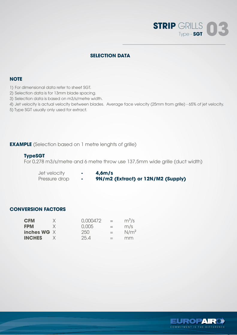
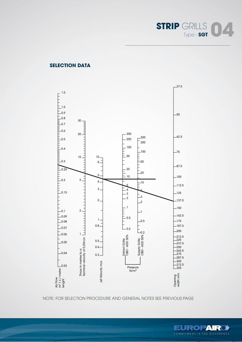
1) For dimensional data refer to sheet SGT.2) Selection data is for 13mm blade spacing.3) Selection data is based on m3/s/metre width.4) Jet velocity is actual velocity between blades. Average face velocity (25mm from grille) - 65% of jet velocity.5) Type SGT usually only used for extract.
NOTE
EXAMPLE (Selection based on 1 metre lenghts of grille)
TypeSGT For 0,278 m3/s/metre and 6 metre throw use 137,5mm wide grille (duct width)
Jet velocity - 4,6m/s Pressure drop - 9N/m2 (Extract) or 12N/M2 (Supply)
CONVERSION FACTORS
CFM X 0,000472 = m3/s FPM X 0,005 = m/s inches WG X 250 = N/m2 INCHES X 25.4 = mm
Type - SGT
STRIP GRILLS 04
SELECTION DATA
NOTE: FOR SELECTION PROCEDURE AND GENERAL NOTES SEE PREVIOUS PAGE
1.0
1.5
30
10
300
300
37.5
50
62.5
75
87.5
100
112.5
125
137.5
150
162.5
175
187.5
200
212.5225
237.5
250
262.5275
287.5
300312.5325
200
100
50
20
10
5
3
2
1
0.5
0.2
200
100
50
20
10
5
4
3
2
1
0.5
0.2
8
5
4
3
2
1
0.8
0.5
0.4
0.3
20
10
5
2
1
0.9
0.8
0.7
0.6
0.5
0.4
0.3
0.25
0.2
0.15
0.1
0.09
0.08
0.07
0.06
0.05
0.04
0.03
Air F
low
m3
/ s
/ m
etre
len
gh
t
Thro
e in
me
tre
s to
a
Term
ina
l ve
loc
ity o
f 0,2
5m
/s
Jet Ve
loc
ity m
/s
Extra
ct G
rille
OBD
- A
DD
50%
Su
pp
ly G
rille
OBD
- A
DD
50%
Op
en
ing
wid
th m
m
Pressure
N/m2
Type - SGS
STRIP GRILLS 05
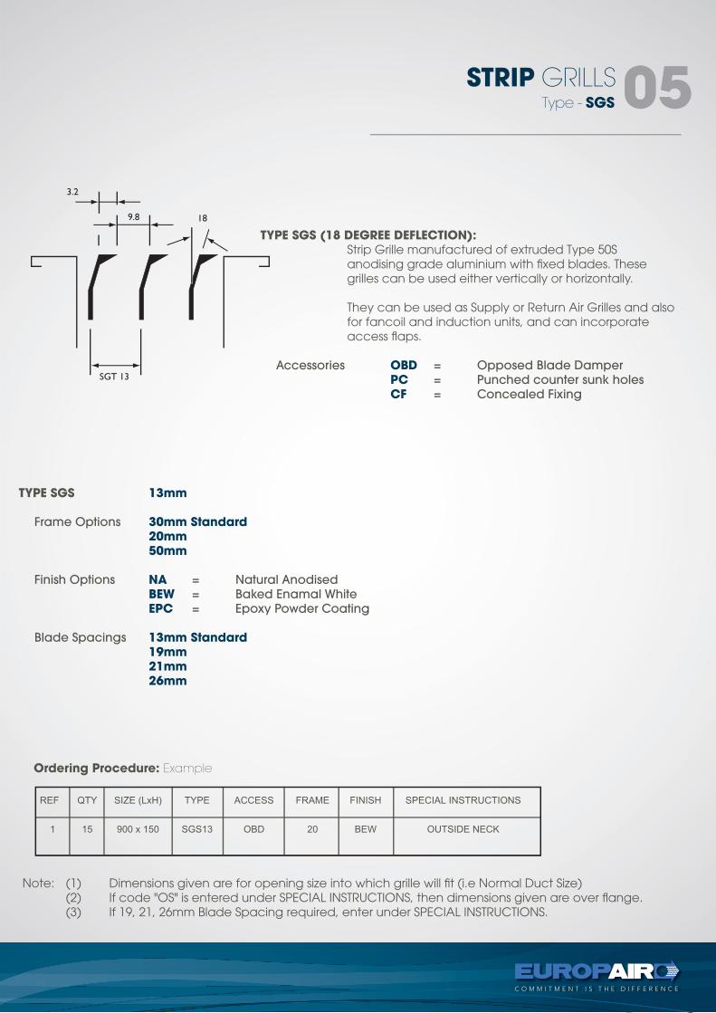
TYPE SGS (18 DEGREE DEFLECTION): Strip Grille manufactured of extruded Type 50S
anodising grade aluminium with fixed blades. These grilles can be used either vertically or horizontally.
They can be used as Supply or Return Air Grilles and also for fancoil and induction units, and can incorporate access flaps.
Accessories OBD = Opposed Blade Damper
PC = Punched counter sunk holes
CF = Concealed Fixing
TYPE SGS 13mm
Frame Options 30mm Standard 20mm 50mm
Finish Options NA = Natural Anodised
BEW = Baked Enamal White
EPC = Epoxy Powder Coating
Blade Spacings 13mm Standard 19mm 21mm 26mm
Ordering Procedure: Example
Note: (1) Dimensions given are for opening size into which grille will fit (i.e Normal Duct Size) (2) If code "OS" is entered under SPECIAL INSTRUCTIONS, then dimensions given are over flange. (3) If 19, 21, 26mm Blade Spacing required, enter under SPECIAL INSTRUCTIONS.
Type - SGS
STRIP GRILLS 06
SELECTION DATA
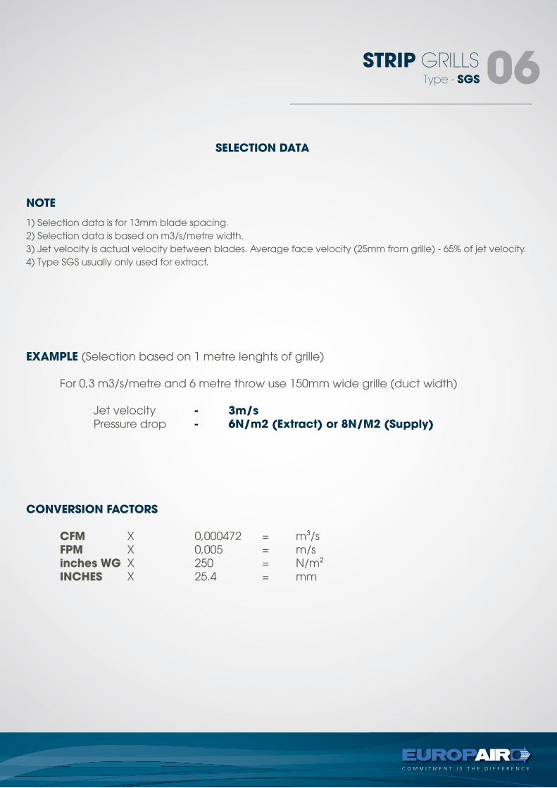
1) Selection data is for 13mm blade spacing.2) Selection data is based on m3/s/metre width.3) Jet velocity is actual velocity between blades. Average face velocity (25mm from grille) - 65% of jet velocity. 4) Type SGS usually only used for extract.
NOTE
EXAMPLE (Selection based on 1 metre lenghts of grille)
For 0,3 m3/s/metre and 6 metre throw use 150mm wide grille (duct width)
Jet velocity - 3m/s Pressure drop - 6N/m2 (Extract) or 8N/M2 (Supply)
CONVERSION FACTORS
CFM X 0,000472 = m3/s FPM X 0,005 = m/s inches WG X 250 = N/m2 INCHES X 25.4 = mm
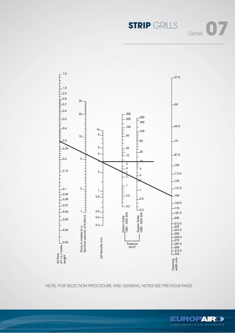
Details
STRIP GRILLS 07
NOTE: FOR SELECTION PROCEDURE AND GENERAL NOTES SEE PREVIOUS PAGE
1.0
1.5
30
10
300
300
37.5
50
62.5
75
87.5
100
112.5
125
137.5
150
162.5
175
187.5
200
212.5225
237.5
250
262.5275
287.5
300312.5325
200
100
50
20
10
5
3
2
1
0.5
0.2
200
100
50
20
10
5
4
3
2
1
0.5
0.2
8
5
4
3
2
1
0.8
0.5
0.4
0.3
20
10
5
2
1
0.9
0.8
0.7
0.6
0.5
0.4
0.3
0.25
0.2
0.15
0.1
0.09
0.08
0.07
0.06
0.05
0.04
0.03
Air F
low
m3
/ s
/ m
etre
len
gh
t
Thro
e in
me
tre
s to
a
Term
ina
l ve
loc
ity o
f 0,2
5m
/s
Jet Ve
loc
ity m
/s
Extra
ct G
rille
OBD
- A
DD
50%
Su
pp
ly G
rille
OBD
- A
DD
50%
Op
en
ing
wid
th m
m
Pressure
N/m2
EGG CRATE GRILLEStechnical
types -EC, ECA
tel +27 11 974 2425
fax +27 11 974 2443
web www.europair-africa.com
email: [email protected]
Europair Africa (Pty) Ltd(a div. of First Strut)
Cnr. Grader and Vuurslag
Spartan Ext. 3
Kempton Park
Johannesburg
C O M M I T M E N T I S T H E D I F F E R E N C E
Tupe - ECP
EGG CRATE GRILLS 02
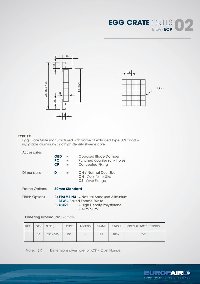
TYPE EC Egg Crate Grille manufactured with frame of extruded Type 50S anodis-
ing grade aluminium and high density styrene core.
Accessories
OBD = Opposed Blade Damper
PC = Punched counter sunk holes
CF = Concealed Fixing
Dimensions D = ON / Normal Duct Size
ON - Over Neck Size OS - Over Flange
Frame Options 30mm Standard Finish Options A) FRAME NA = Natural Anodised Aliminium
BEW = Baked Enamel White
B) CORE = High Density Polystyrene
= Aliminium
Note: (1) Dimensions given are for 'OS' = Over Flange
Ordering Procedure: Example
Tupe - ECA
EGG CRATE GRILLS 03
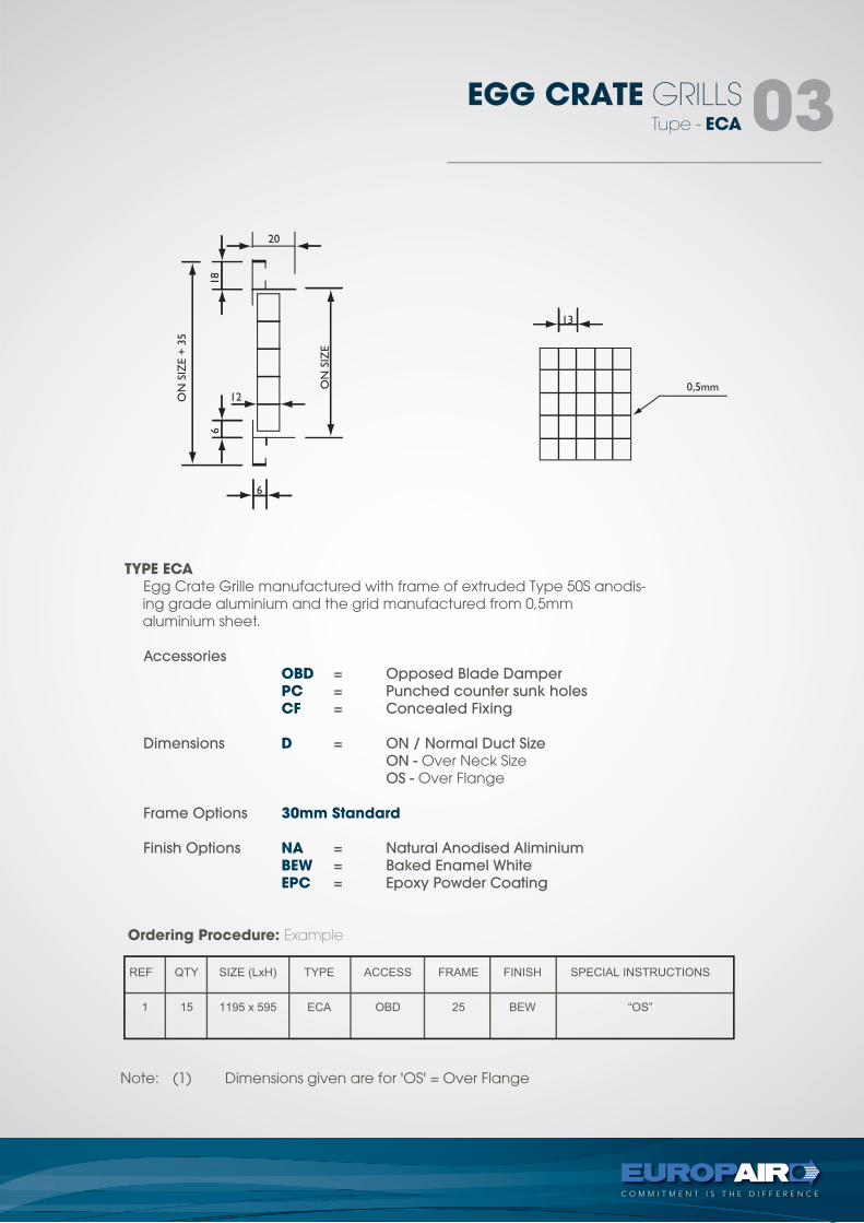
TYPE ECA Egg Crate Grille manufactured with frame of extruded Type 50S anodis-
ing grade aluminium and the grid manufactured from 0,5mm aluminium sheet.
Accessories
OBD = Opposed Blade Damper
PC = Punched counter sunk holes
CF = Concealed Fixing
Dimensions D = ON / Normal Duct Size
ON - Over Neck Size OS - Over Flange
Frame Options 30mm Standard Finish Options NA = Natural Anodised Aliminium
BEW = Baked Enamel White
EPC = Epoxy Powder Coating
Note: (1) Dimensions given are for 'OS' = Over Flange
Ordering Procedure: Example
CORES
EGG CRATE GRILLS 04
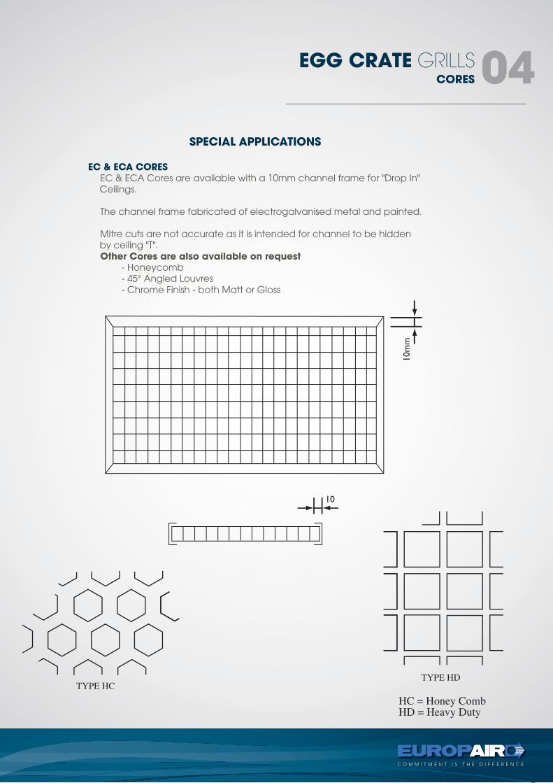
SPECIAL APPLICATIONS
EC & ECA CORES EC & ECA Cores are available with a 10mm channel frame for "Drop In"
Ceilings. The channel frame fabricated of electrogalvanised metal and painted. Mitre cuts are not accurate as it is intended for channel to be hidden
by ceiling "T". Other Cores are also available on request - Honeycomb - 45° Angled Louvres - Chrome Finish - both Matt or Gloss
Details
EGG CRATE GRILLS 05
15010080
6040
20
1510864
2
10.80.60.4
0.2
0.1
0.05
15
10
8
6
5
4
3
2
1.5
1.0
0.75
0.50
0.25
1.8
2.0
1.6
1.4
1.2
1.0
.9
.8
.7
.6
.5
.4
.3
.2
.15
.10
.09
.08
.07
.06
100
150
200
250
300
350
400
450
500
550
600
100
150
200
250
310
350
400
450
500
550
600
650
700
750
800850
900
95010001050110011501200
2251501209060
30
151296
3
1.51.20.90.6
0.3
0.15
0.075
AA
HEIG
HT
mm
WID
TH m
m
Grilll
e +
OBD
Grilll
e
Ve
loc
ity m
/s
Air F
low
m3
/ s
Pressure
N/m2
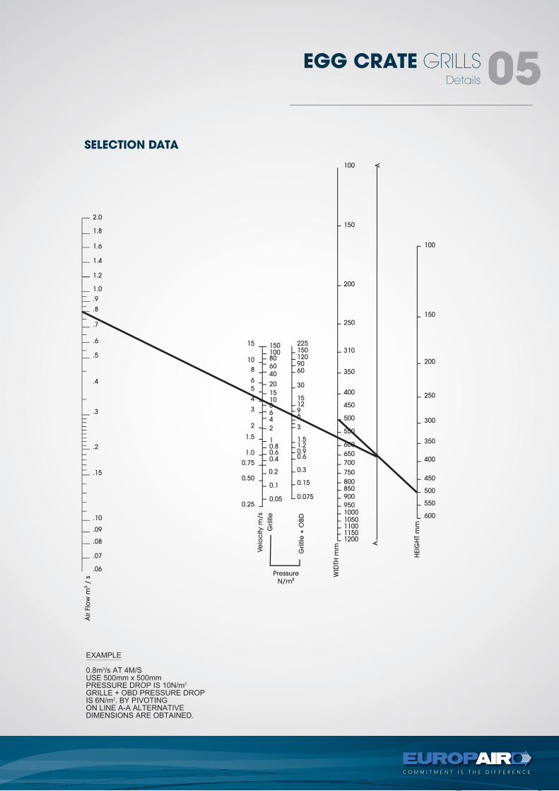
SELECTION DATA
DOOR GRILLEStechnical
types -DG, DG-DR
tel +27 11 974 2425
fax +27 11 974 2443
web www.europair-africa.com
email: [email protected]
Europair Africa (Pty) Ltd(a div. of First Strut)
Cnr. Grader and Vuurslag
Spartan Ext. 3
Kempton Park
Johannesburg
C O M M I T M E N T I S T H E D I F F E R E N C E
Type - DG
DOOR GRILLS 02
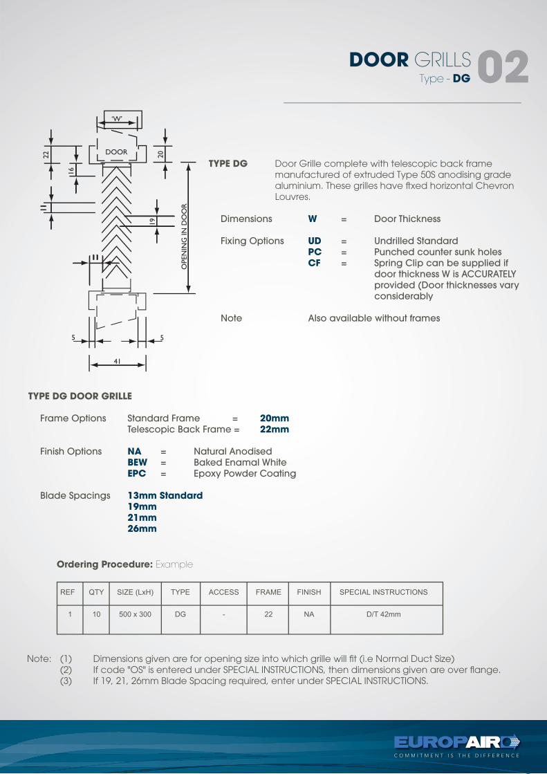
TYPE DG Door Grille complete with telescopic back frame manufactured of extruded Type 50S anodising grade aluminium. These grilles have ftxed horizontal Chevron Louvres.
Dimensions W = Door Thickness
Fixing Options UD = Undrilled Standard
PC = Punched counter sunk holes
CF = Spring Clip can be supplied if
door thickness W is ACCURATELY
provided (Door thicknesses vary
considerably
Note Also available without frames
TYPE DG DOOR GRILLE
Frame Options Standard Frame = 20mm Telescopic Back Frame = 22mm
Finish Options NA = Natural Anodised
BEW = Baked Enamal White
EPC = Epoxy Powder Coating
Blade Spacings 13mm Standard 19mm 21mm 26mm
Note: (1) Dimensions given are for opening size into which grille will fit (i.e Normal Duct Size) (2) If code "OS" is entered under SPECIAL INSTRUCTIONS, then dimensions given are over flange. (3) If 19, 21, 26mm Blade Spacing required, enter under SPECIAL INSTRUCTIONS.
Ordering Procedure: Example
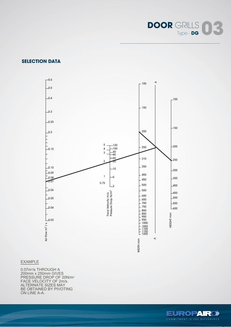
SELECTION DATA
Type - DG
DOOR GRILLS 03
100
150
200
250
300
350
400
450
500
550
600
HEIG
HT
mm
100
1205
4
3
2
1
0.75
1005040
3020
10
5
2
150
200
250
310
350
400
450
500
550
600
650
700
750
8008509009501000
1050110011501200
0.6
0.5
0.4
0.3
0.25
0.2
0.15
0.10
0.09
0.08
0.07
0.06
0.05
0.04
0.03
Air F
low
m3
/ s
AA
WID
TH m
m
Fac
e V
elo
city m
/s
Pre
ssu
re D
rop
N/m
2
FIXED BLADE CEILING DIFFUSER - CD
Details
DOOR GRILLS 04Type - DG-DR
DOOR GRILLS 04
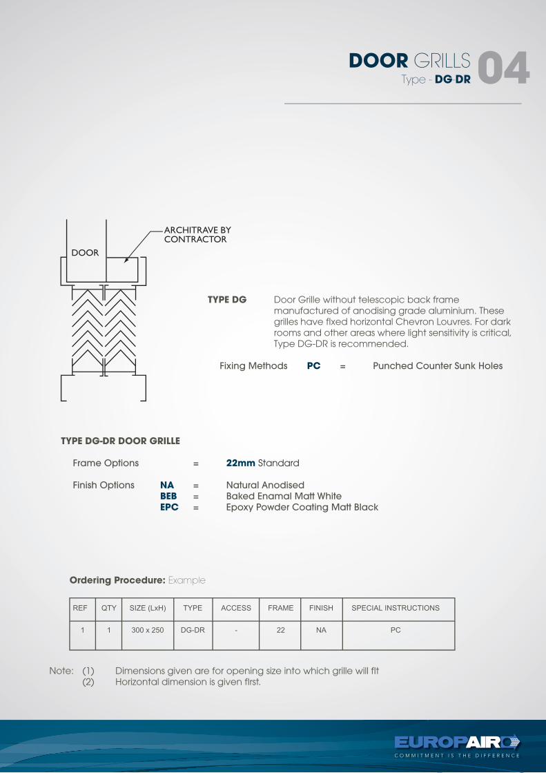
TYPE DG Door Grille without telescopic back frame manufactured of anodising grade aluminium. These grilles have fIxed horizontal Chevron Louvres. For dark rooms and other areas where light sensitivity is critical, Type DG-DR is recommended.
Fixing Methods PC = Punched Counter Sunk Holes
TYPE DG-DR DOOR GRILLE
Frame Options = 22mm Standard
Finish Options NA = Natural Anodised
BEB = Baked Enamal Matt White
EPC = Epoxy Powder Coating Matt Black
Ordering Procedure: Example
Note: (1) Dimensions given are for opening size into which grille will fIt (2) Horizontal dimension is given fIrst.

tel +27 11 974 2425
fax +27 11 974 2443
web www.europair-africa.com
email: [email protected]
Europair Africa (Pty) Ltd(a div. of First Strut)
Cnr. Grader and Vuurslag
Spartan Ext. 3
Kempton Park
Johannesburg
WEATHER LOUVREStechnical
C O M M I T M E N T I S T H E D I F F E R E N C E
type - WL
Type - WPL
WEATHER LOUVRES02
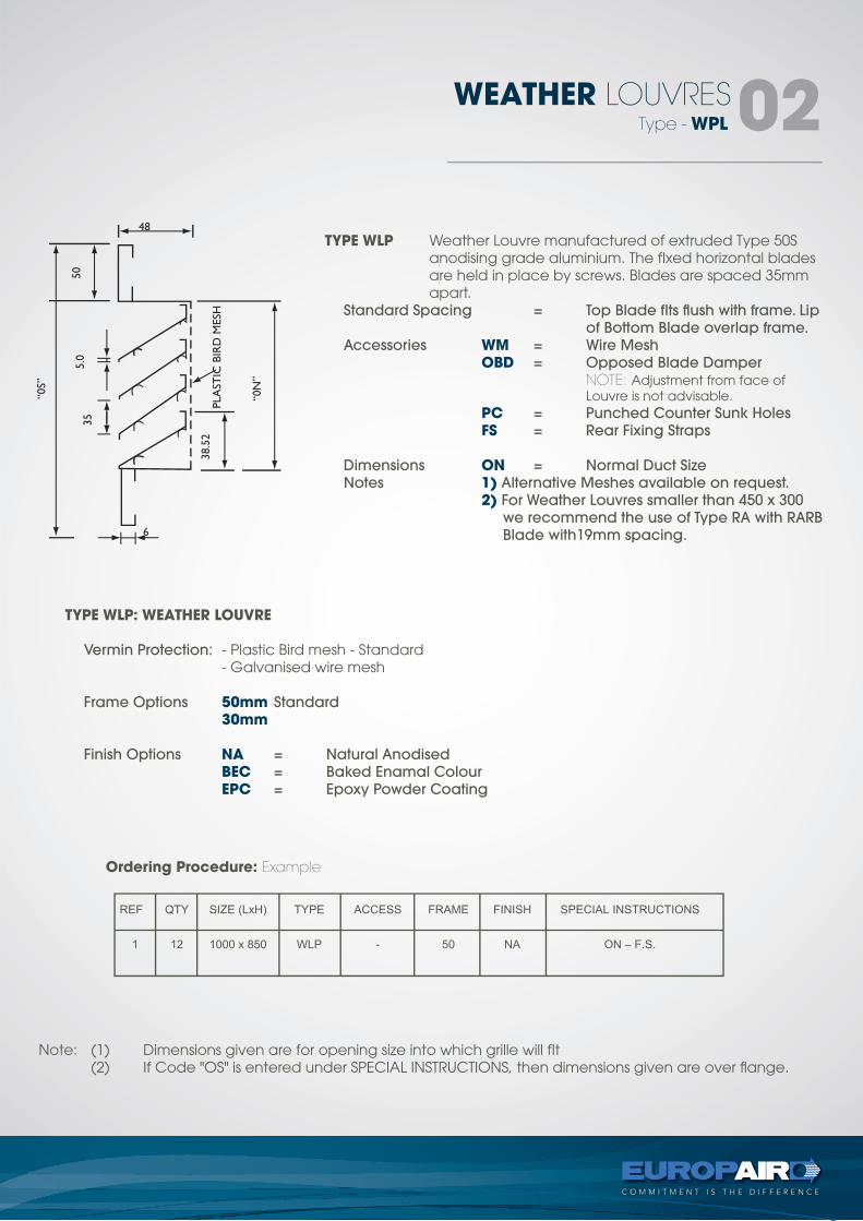
TYPE WLP Weather Louvre manufactured of extruded Type 50S anodising grade aluminium. The fIxed horizontal blades are held in place by screws. Blades are spaced 35mm apart.
Standard Spacing = Top Blade fIts flush with frame. Lip
of Bottom Blade overlap frame.
Accessories WM = Wire Mesh
OBD = Opposed Blade Damper
NOTE: Adjustment from face of Louvre is not advisable. PC = Punched Counter Sunk Holes
FS = Rear Fixing Straps
Dimensions ON = Normal Duct Size
Notes 1) Alternative Meshes available on request.
2) For Weather Louvres smaller than 450 x 300
we recommend the use of Type RA with RARB
Blade with19mm spacing.
TYPE WLP: WEATHER LOUVRE
Vermin Protection: - Plastic Bird mesh - Standard - Galvanised wire mesh
Frame Options 50mm Standard
30mm
Finish Options NA = Natural Anodised
BEC = Baked Enamal Colour
EPC = Epoxy Powder Coating
Note: (1) Dimensions given are for opening size into which grille will fIt (2) If Code "OS" is entered under SPECIAL INSTRUCTIONS, then dimensions given are over flange.
Ordering Procedure: Example
Type - WPL
WEATHER LOUVRES03
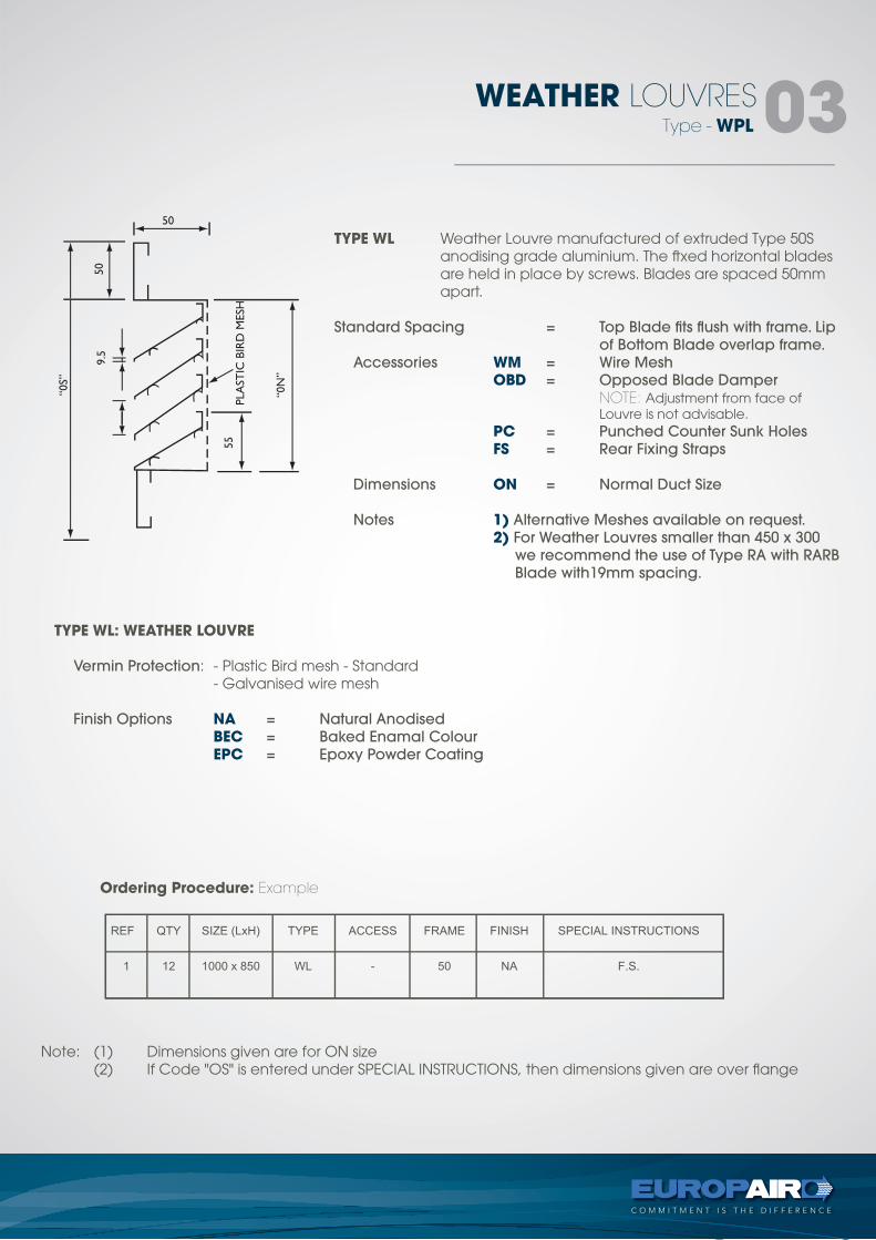
TYPE WL Weather Louvre manufactured of extruded Type 50S anodising grade aluminium. The ftxed horizontal blades are held in place by screws. Blades are spaced 50mm apart.
Standard Spacing = Top Blade fits flush with frame. Lip
of Bottom Blade overlap frame.
Accessories WM = Wire Mesh
OBD = Opposed Blade Damper
NOTE: Adjustment from face of Louvre is not advisable. PC = Punched Counter Sunk Holes
FS = Rear Fixing Straps
Dimensions ON = Normal Duct Size
Notes 1) Alternative Meshes available on request.
2) For Weather Louvres smaller than 450 x 300
we recommend the use of Type RA with RARB
Blade with19mm spacing.
TYPE WL: WEATHER LOUVRE
Vermin Protection: - Plastic Bird mesh - Standard - Galvanised wire mesh
Finish Options NA = Natural Anodised
BEC = Baked Enamal Colour
EPC = Epoxy Powder Coating
Ordering Procedure: Example
Note: (1) Dimensions given are for ON size (2) If Code "OS" is entered under SPECIAL INSTRUCTIONS, then dimensions given are over flange
Type - WL
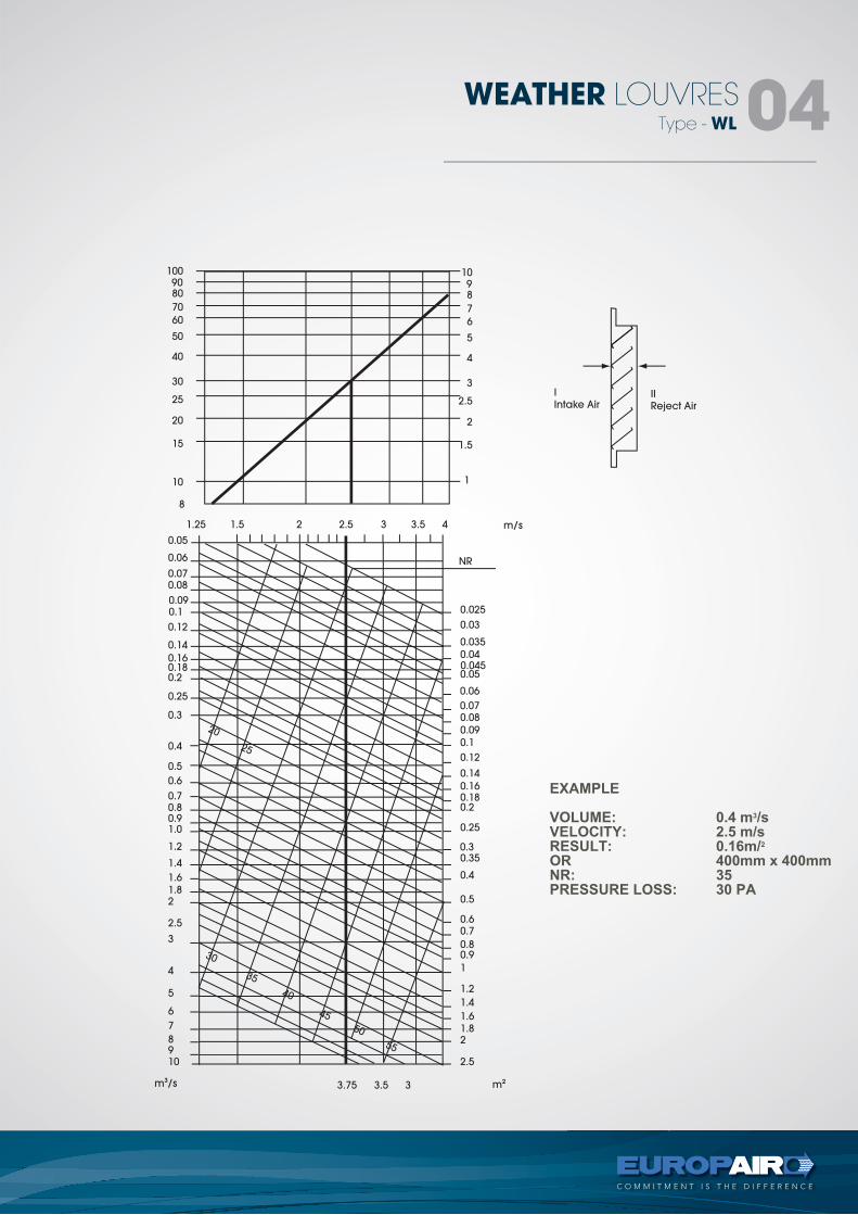
WEATHER LOUVRES04
1009080
70
60
50
40
30
25
20
15
10
10
I
Intake Air
m/s
NR
II
Reject Air
98
7
6
5
4
3
2.5
2
1.5
1
8
1.25
0.16
0.14
0.12
0.10.09
0.080.07
0.06
0.05
0.025
0.03
0.035
0.040.0450.05
0.06
0.070.08
0.09
0.1
0.12
0.14
0.160.180.2
0.25
0.30.35
0.4
0.5
0.70.6
0.80.9
1
1.2
1.4
1.6
1.82
2.5
m23.75m3/s
30
20
25
35
40
45
55
50
3.5 3
0.180.2
0.25
0.3
0.4
0.5
0.6
0.70.80.91.0
1.2
1.4
1.6
1.82
2.5
3
4
5
6
7
8910
1.5 2 2.5 3 3.5 4
tel +27 11 974 2425
fax +27 11 974 2443
web www.europair-africa.com
email: [email protected]
Europair Africa (Pty) Ltd(a div. of First Strut)
Cnr. Grader and Vuurslag
Spartan Ext. 3
Kempton Park
Johannesburg
FLOOR GRILLEStechnical
C O M M I T M E N T I S T H E D I F F E R E N C E
type - FG
Type - FG
FLOOR GRILLES 02
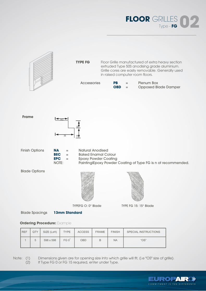
TYPE FG Floor Grille manufactured of extra heavy section extruded Type 50S anodising grade aluminium. Grille cores are easily removable. Generally used in raised computer room floors.
Accessories PB = Plenum Box
OBD = Opposed Blade Damper
Frame
Finish Options NA = Natural Anodised
BEC = Baked Enamal Colour
EPC = Epoxy Powder Coating
NOTE: PaintinglEpoxy Powder Coating of Type FG is n ot recommended.
Blade Options
Blade Spacings 13mm Standard
TYPEFG O: 0° Blade TYPE FG 15: 15° Blade
Note: (1) Dimensions given are for opening size into which grille will fit, (i.e "OS" size of grille). (2) If Type FG 0 or FG 15 required, enter under Type.
Ordering Procedure: Example
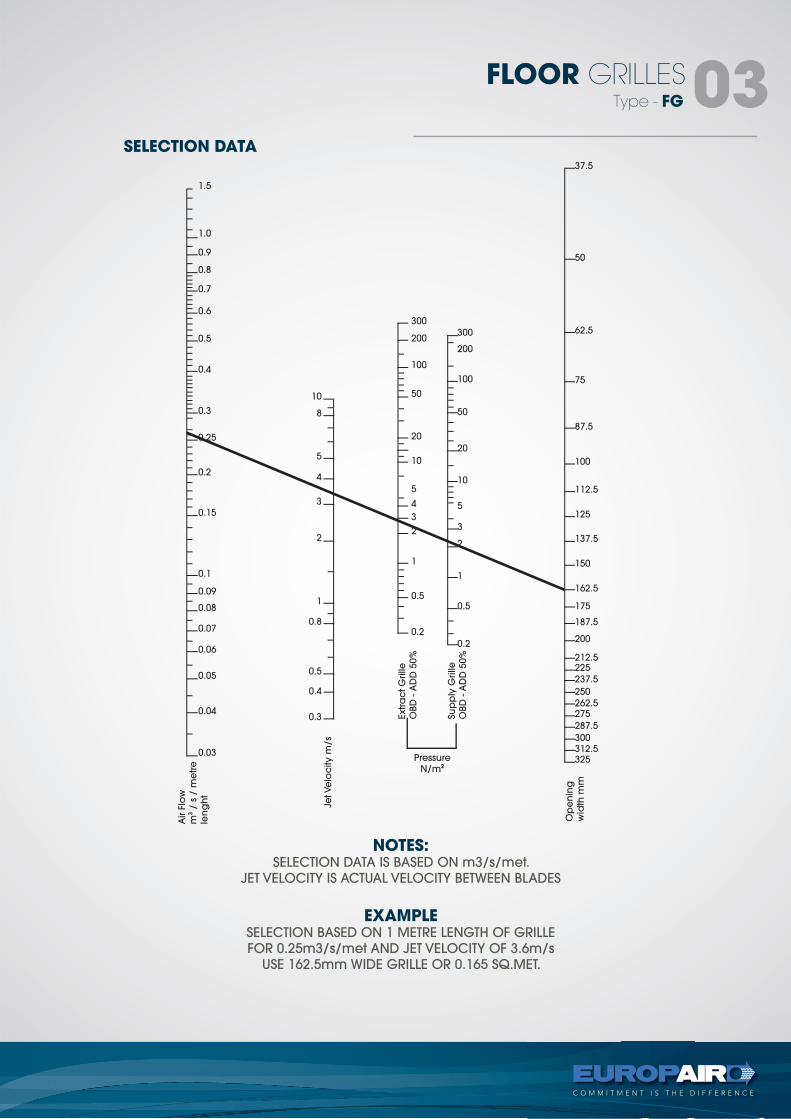
NOTES:SELECTION DATA IS BASED ON m3/s/met.
JET VELOCITY IS ACTUAL VELOCITY BETWEEN BLADES
EXAMPLESELECTION BASED ON 1 METRE LENGTH OF GRILLE
FOR 0.25m3/s/met AND JET VELOCITY OF 3.6m/s
USE 162.5mm WIDE GRILLE OR 0.165 SQ.MET.
Type - FG
FLOOR GRILLES03
1.0
1.5
10
300
300
37.5
50
62.5
75
87.5
100
112.5
125
137.5
150
162.5
175
187.5
200
212.5225
237.5
250
262.5275
287.5
300312.5325
200
100
50
20
10
5
3
2
1
0.5
0.2
200
100
50
20
10
5
4
3
2
1
0.5
0.2
8
5
4
3
2
1
0.8
0.5
0.4
0.3
0.9
0.8
0.7
0.6
0.5
0.4
0.3
0.25
0.2
0.15
0.1
0.09
0.08
0.07
0.06
0.05
0.04
0.03
Air F
low
m3
/ s
/ m
etre
len
gh
t
Jet Ve
loc
ity m
/s
Extra
ct G
rille
OBD
- A
DD
50%
Su
pp
ly G
rille
OBD
- A
DD
50%
Op
en
ing
wid
th m
m
Pressure
N/m2
SELECTION DATA
tel +27 11 974 2425fax +27 11 974 2443web www.europair-africa.comemail: [email protected]
Europair Africa (Pty) Ltd(a div. of First Strut)
Cnr. Grader and VuurslagSpartan Ext. 3
Kempton ParkJohannesburg
OPPOSED BLADE DAMPERtechnical
C O M M I T M E N T I S T H E D I F F E R E N C E
types -OBD
Type - OBD
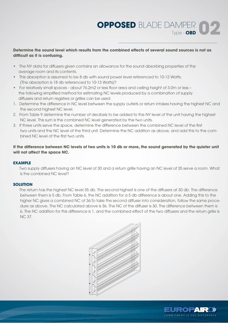
OPPOSED BLADE DAMPER 02Determine the sound level which results from the combined effects of several sound sources is not as
difficult as it is confusing.
• The NY data for diffusers given contains an allowance for the sound absorbing properties of the average room and its contents.• This absorption is assumed to be 8 db with sound power level referenced to 10-12 Watts.
(The absorption is 18 db referenced to 10-13 Watts)?• For relatively small spaces - about 76.2m2 or less floor area and ceiling height of 3.0m or less – the following simplified method for estimating NC levels produced by a combination of supply diffusers and return registers or grilles can be used:1. Determine the difference in NC level between the supply outlets or return intakes having the highest NC and
the second highest NC level.2. From Table 9 determine the number of decibels to be added to the NY level of the unit having the highest
NC level. This sum is the combined NC level generated by the two units.3. If three units serve the space, determine the difference between the combined NC level of the first
two units and the NC level of the third unit. Determine the NC addition as above, and add this to the com-bined NC level of the first two units.
If the difference between NC levels of two units is 10 db or more, the sound generated by the quieter unit
will not affect the space NC.
EXAMPLE
Two supply diffusers having an NC level of 30 and a return grille having an NC level of 35 serve a room. What is the combined NC level?
SOLUTION
The return has the highest NC level 35 db. The second highest is one of the diffusers at 30 db. The difference between them is 5 db. From Table 6, the NC addition for a 5 db difference is about one. Adding this to the higher NC gives a combined NC of 36.To take the second diffuser into consideration, follow the same proce-dure as above. The NC calculated above is 36. The NC of the diffuser is 30. The difference between them is 6. The NC addition for this difference is 1, and the combined effect of the two diffusers and the return grille is NC 37.
Type - OBD
OPPOSED BLADE DAMPER 03
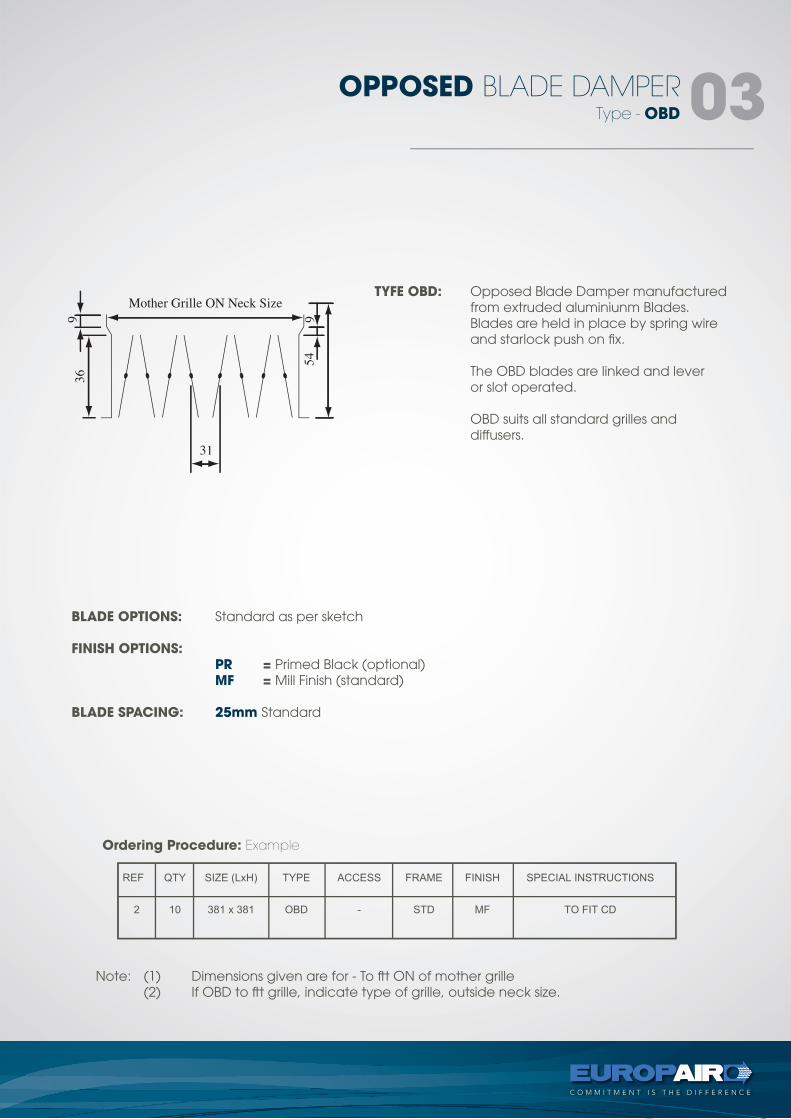
TYFE OBD: Opposed Blade Damper manufactured from extruded aluminiunm Blades. Blades are held in place by spring wire and starlock push on fix. The OBD blades are linked and lever or slot operated. OBD suits all standard grilles and diffusers.
BLADE OPTIONS: Standard as per sketch
FINISH OPTIONS: PR = Primed Black (optional) MF = Mill Finish (standard)
BLADE SPACING: 25mm Standard
Note: (1) Dimensions given are for - To ftt ON of mother grille (2) If OBD to ftt grille, indicate type of grille, outside neck size.
Ordering Procedure: Example
tel +27 11 974 2425fax +27 11 974 2443web www.europair-africa.comemail: [email protected]
Europair Africa (Pty) Ltd(a div. of First Strut)
Cnr. Grader and VuurslagSpartan Ext. 3
Kempton ParkJohannesburg
CONCEALED FIXINGStechnical
C O M M I T M E N T I S T H E D I F F E R E N C E
Details
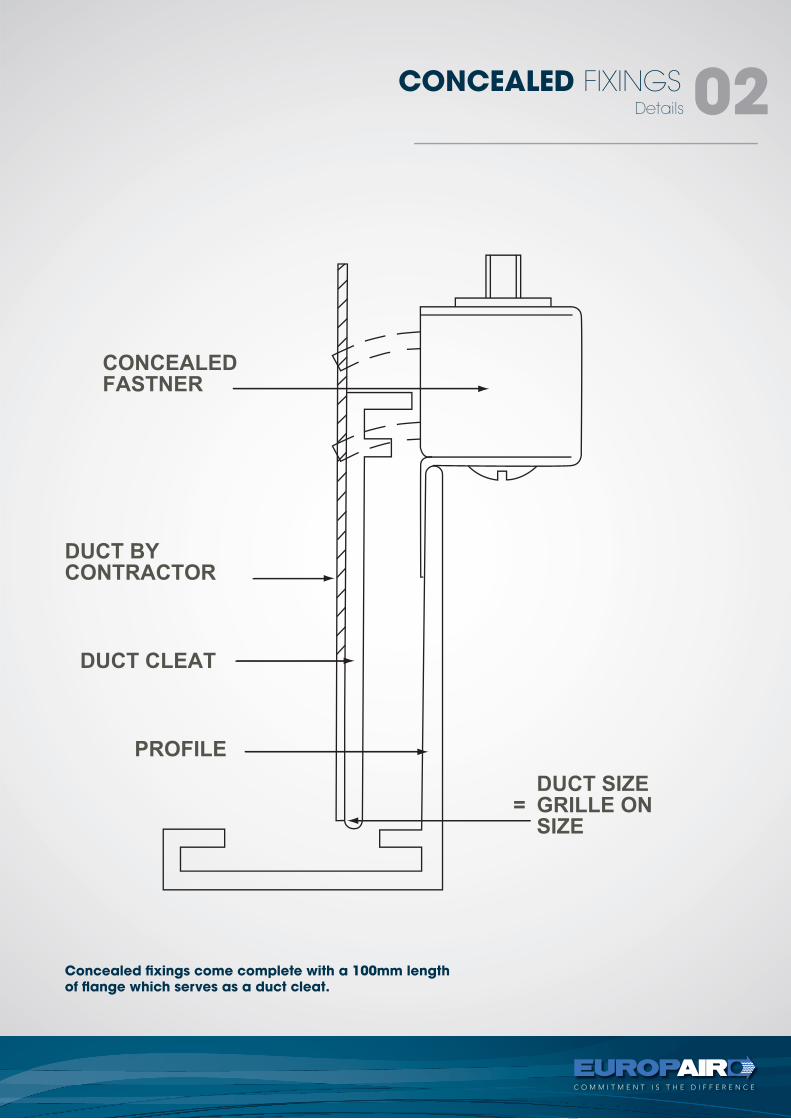
CONCEALED FIXINGS 02
Concealed fixings come complete with a 100mm lengthof flange which serves as a duct cleat.
tel +27 11 974 2425fax +27 11 974 2443web www.europair-africa.comemail: [email protected]
Europair Africa (Pty) Ltd(a div. of First Strut)
Cnr. Grader and VuurslagSpartan Ext. 3
Kempton ParkJohannesburg
PLENUM BOXtechnical
C O M M I T M E N T I S T H E D I F F E R E N C E
types -PB
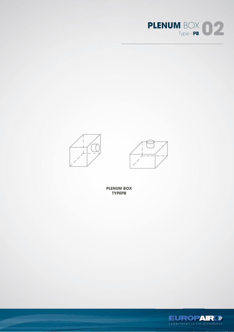
PLENUM BOXTYPEPB
Type - PB
PLENUM BOX 02
Type - PB
PLENUM BOX 03
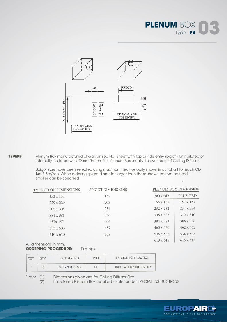
TYPEPB Plenum Box manufactured of Galvanised Flat Sheet with top or side entry spigot - Uninsulated or internally insulated with lOmm Thermaflex. Plenum Box usually fits over neck of Ceiling Diffuser.
Spigot sizes have been selected using maximum neck velocity shown in our chart for each CD. i.e: 3.5m/sec. When ordering spigot diameter larger than those shown cannot be used , smaller can be specified.
All dimensions in mm.ORDERING PROCEDURE: Example
Note: (1) Dimensions given are for Ceiling Diffuser Size. (2) If insulated Plenum Box required - Enter under SPECIAL INSTRUCTIONS
tel +27 11 974 2425fax +27 11 974 2443web www.europair-africa.comemail: [email protected]
Europair Africa (Pty) Ltd(a div. of First Strut)
Cnr. Grader and VuurslagSpartan Ext. 3
Kempton ParkJohannesburg
CUSTOM MADE PRODUCTStechnical
C O M M I T M E N T I S T H E D I F F E R E N C E
types -CM
Type - CM
CUSTOM MADE PRODUCTS 02
CUSTOM MADETYPE CM
Type - CM
CUSTOM MADE PRODUCTS 03
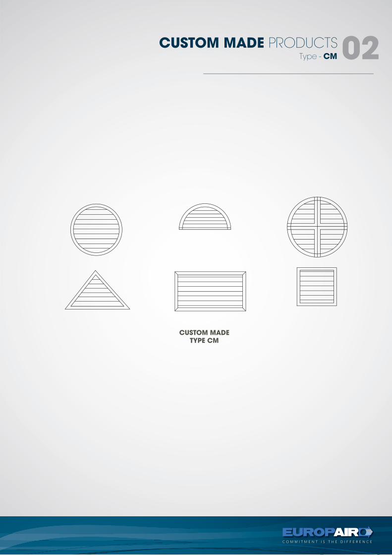
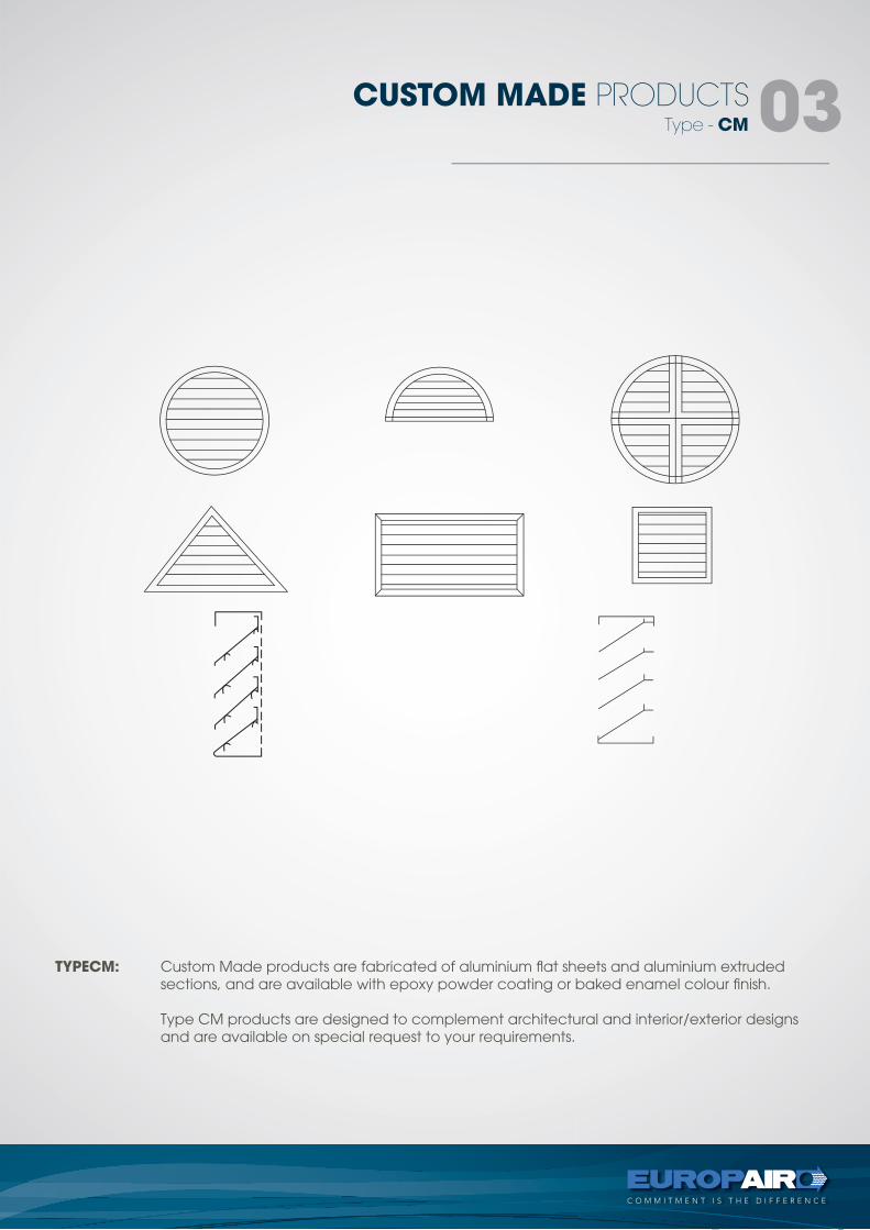
TYPECM: Custom Made products are fabricated of aluminium flat sheets and aluminium extruded sections, and are available with epoxy powder coating or baked enamel colour finish.
Type CM products are designed to complement architectural and interior/exterior designs and are available on special request to your requirements.
tel +27 11 974 2425fax +27 11 974 2443web www.europair-africa.comemail: [email protected]
Europair Africa (Pty) Ltd(a div. of First Strut)
Cnr. Grader and VuurslagSpartan Ext. 3
Kempton ParkJohannesburg
PLASTIC DIFFUSERStechnical
C O M M I T M E N T I S T H E D I F F E R E N C E
T-Bar Register, Surface Mounted Register,Side Wall Register
T-Bar Register
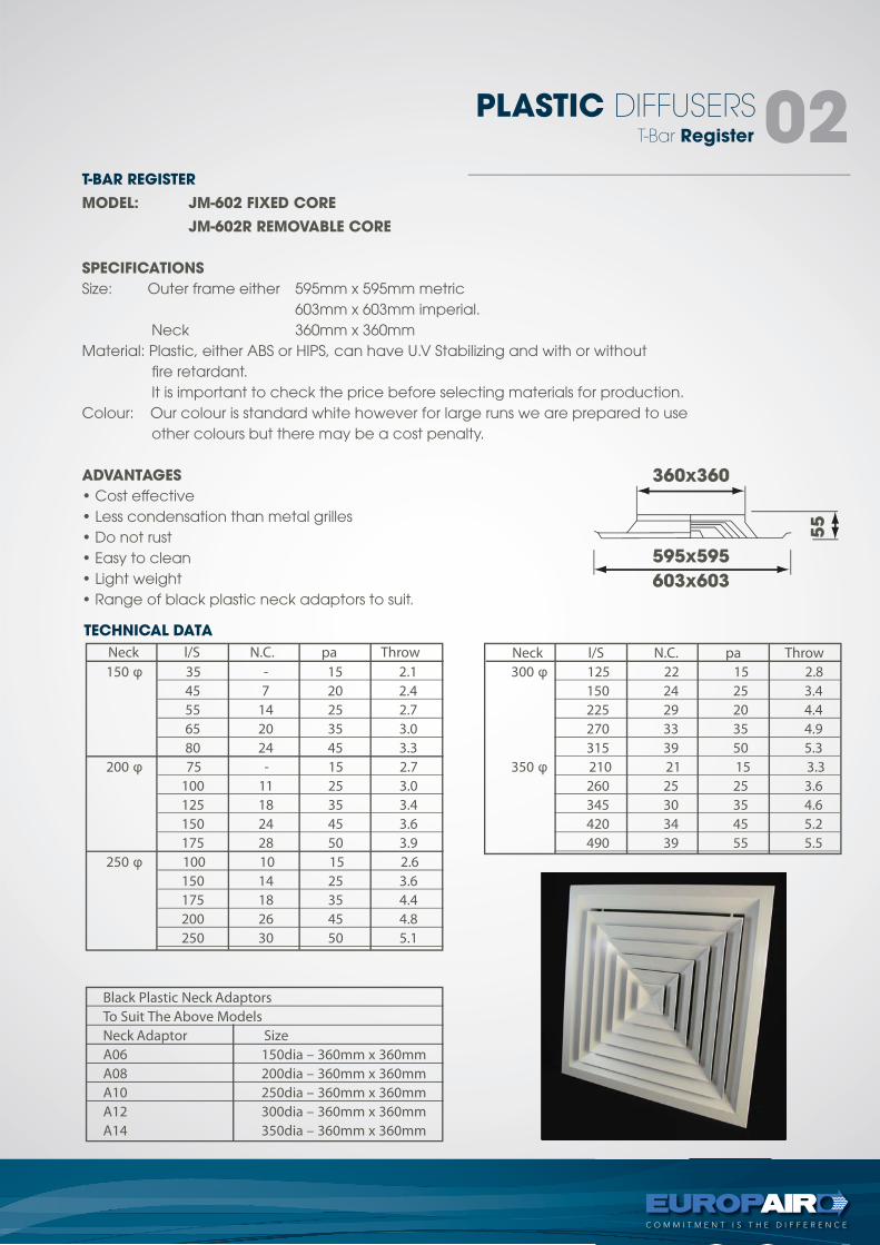
PLASTIC DIFFUSERS02T-BAR REGISTER
MODEL: JM-602 FIXED CORE
JM-602R REMOVABLE CORE
SPECIFICATIONS
Size: Outer frame either 595mm x 595mm metric 603mm x 603mm imperial. Neck 360mm x 360mmMaterial: Plastic, either ABS or HIPS, can have U.V Stabilizing and with or without fire retardant. It is important to check the price before selecting materials for production.Colour: Our colour is standard white however for large runs we are prepared to use other colours but there may be a cost penalty.
ADVANTAGES
• Cost effective• Less condensation than metal grilles• Do not rust • Easy to clean• Light weight • Range of black plastic neck adaptors to suit.
Neck l/S N.C. pa Throw 150 φ
200 φ
250 φ
35 - 15 2.1 45 7 20 2.4 55 14 25 2.7 65 20 35 3.0 80 24 45 3.3
75 - 15 2.7 100 11 25 3.0 125 18 35 3.4 150 24 45 3.6 175 28 50 3.9
100 10 15 2.6 150 14 25 3.6 175 18 35 4.4 200 26 45 4.8 250 30 50 5.1
φ Neck l/S N.C. pa Throw 300 125 22 15 2.8 150 24 25 3.4 225 29 20 4.4 270 33 35 4.9 315 39 50 5.3 350 φ 210 21 15 3.3 260 25 25 3.6 345 30 35 4.6 420 34 45 5.2 490 39 55 5.5
Black Plastic Neck Adaptors To Suit The Above Models Neck Adaptor Size A06 150dia – 360mm x 360mm A08 200dia – 360mm x 360mm A10 250dia – 360mm x 360mm A12 300dia – 360mm x 360mm A14 350dia – 360mm x 360mm
TECHNICAL DATA
360x360
595x595
603x603
55
T-Bar Register
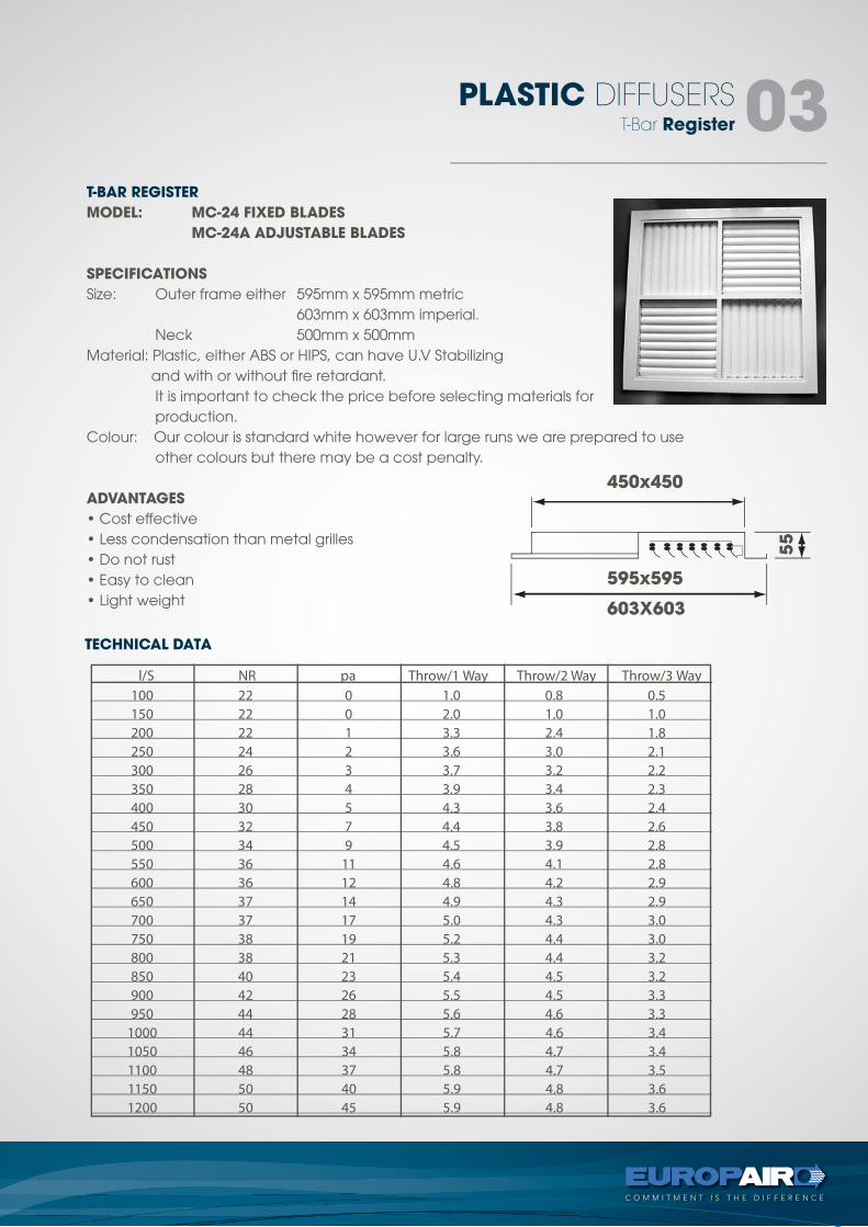
PLASTIC DIFFUSERS 03
l/S NR pa Throw/1 Way Throw/2 Way Throw/3 Way 100 22 0 1.0 0.8 0.5 150 22 0 2.0 1.0 1.0 200 22 1 3.3 2.4 1.8 250 24 2 3.6 3.0 2.1 300 26 3 3.7 3.2 2.2 350 28 4 3.9 3.4 2.3 400 30 5 4.3 3.6 2.4 450 32 7 4.4 3.8 2.6 500 34 9 4.5 3.9 2.8 550 36 11 4.6 4.1 2.8 600 36 12 4.8 4.2 2.9 650 37 14 4.9 4.3 2.9 700 37 17 5.0 4.3 3.0 750 38 19 5.2 4.4 3.0 800 38 21 5.3 4.4 3.2 850 40 23 5.4 4.5 3.2 900 42 26 5.5 4.5 3.3 950 44 28 5.6 4.6 3.3 1000 44 31 5.7 4.6 3.4 1050 46 34 5.8 4.7 3.4 1100 48 37 5.8 4.7 3.5 1150 50 40 5.9 4.8 3.6 1200 50 45 5.9 4.8 3.6
TECHNICAL DATA
T-BAR REGISTER
MODEL: MC-24 FIXED BLADES
MC-24A ADJUSTABLE BLADES
SPECIFICATIONS
Size: Outer frame either 595mm x 595mm metric 603mm x 603mm imperial. Neck 500mm x 500mmMaterial: Plastic, either ABS or HIPS, can have U.V Stabilizing and with or without fire retardant. It is important to check the price before selecting materials for production.Colour: Our colour is standard white however for large runs we are prepared to use other colours but there may be a cost penalty.
ADVANTAGES
• Cost effective• Less condensation than metal grilles• Do not rust • Easy to clean• Light weight
450x450
603X603
595x595
55
Surface Mounted Register
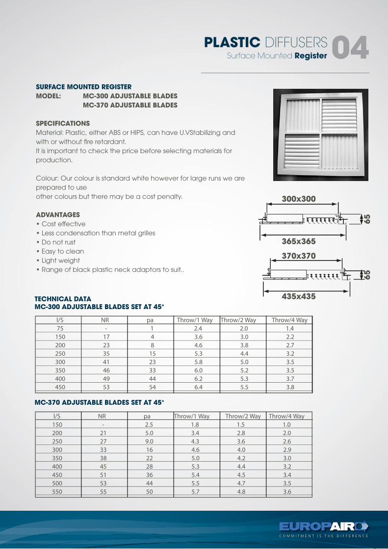
PLASTIC DIFFUSERS 04
l/S NR pa Throw/1 Way Throw/2 Way Throw/4 Way 75 - 1 2.4 2.0 1.4 150 17 4 3.6 3.0 2.2 200 23 8 4.6 3.8 2.7 250 35 15 5.3 4.4 3.2 300 41 23 5.8 5.0 3.5 350 46 33 6.0 5.2 3.5 400 49 44 6.2 5.3 3.7 450 53 54 6.4 5.5 3.8
l/S NR pa Throw/1 Way Throw/2 Way Throw/4 Way 150 - 2.5 1.8 1.5 1.0 200 21 5.0 3.4 2.8 2.0 250 27 9.0 4.3 3.6 2.6 300 33 16 4.6 4.0 2.9 350 38 22 5.0 4.2 3.0 400 45 28 5.3 4.4 3.2 450 51 36 5.4 4.5 3.4 500 53 44 5.5 4.7 3.5 550 55 50 5.7 4.8 3.6
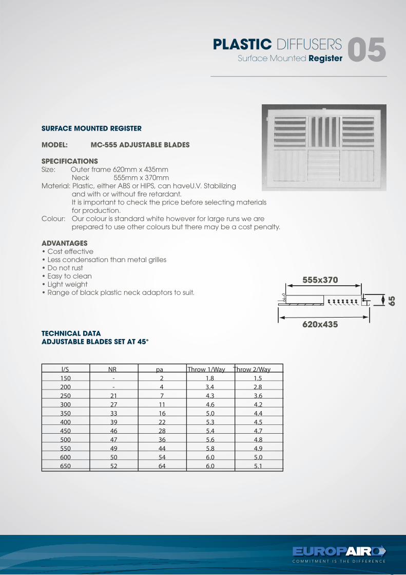
SURFACE MOUNTED REGISTER
MODEL: MC-300 ADJUSTABLE BLADES
MC-370 ADJUSTABLE BLADES
SPECIFICATIONS
Material: Plastic, either ABS or HIPS, can have U.VStabilizing andwith or without fire retardant.It is important to check the price before selecting materials forproduction.
Colour: Our colour is standard white however for large runs we areprepared to useother colours but there may be a cost penalty.
ADVANTAGES
• Cost effective• Less condensation than metal grilles• Do not rust• Easy to clean• Light weight• Range of black plastic neck adaptors to suit..
TECHNICAL DATAMC-300 ADJUSTABLE BLADES SET AT 45°
MC-370 ADJUSTABLE BLADES SET AT 45°
300x300
365x365
370x370
435x435
65
65
Surface Mounted Register
PLASTIC DIFFUSERS 05
l/S NR pa Throw 1/Way Throw 2/Way 150 - 2 1.8 1.5 200 - 4 3.4 2.8 250 21 7 4.3 3.6 300 27 11 4.6 4.2 350 33 16 5.0 4.4 400 39 22 5.3 4.5 450 46 28 5.4 4.7 500 47 36 5.6 4.8 550 49 44 5.8 4.9 600 50 54 6.0 5.0 650 52 64 6.0 5.1
SURFACE MOUNTED REGISTER
MODEL: MC-555 ADJUSTABLE BLADES
SPECIFICATIONSSize: Outer frame 620mm x 435mm Neck 555mm x 370mmMaterial: Plastic, either ABS or HIPS, can haveU.V. Stabilizing and with or without fire retardant. It is important to check the price before selecting materials for production.Colour: Our colour is standard white however for large runs we are prepared to use other colours but there may be a cost penalty.
ADVANTAGES• Cost effective• Less condensation than metal grilles• Do not rust• Easy to clean• Light weight• Range of black plastic neck adaptors to suit.
TECHNICAL DATAADJUSTABLE BLADES SET AT 45°
555x370
620x435
65
Side Wall Register
PLASTIC DIFFUSERS 06
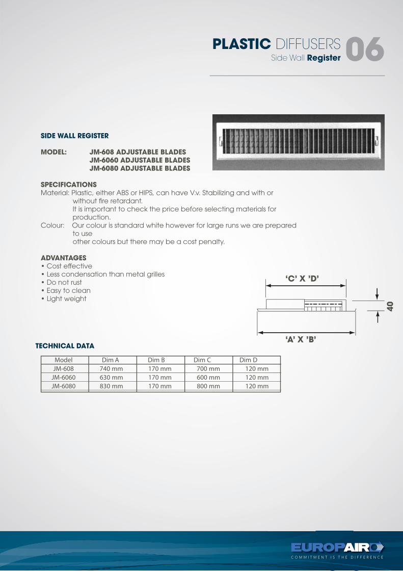
Model Dim A Dim B Dim C Dim D JM-608 740 mm 170 mm 700 mm 120 mm JM-6060 630 mm 170 mm 600 mm 120 mm JM-6080 830 mm 170 mm 800 mm 120 mm
SIDE WALL REGISTER
MODEL: JM-608 ADJUSTABLE BLADES JM-6060 ADJUSTABLE BLADES JM-6080 ADJUSTABLE BLADES
SPECIFICATIONSMaterial: Plastic, either ABS or HIPS, can have V.v. Stabilizing and with or without fire retardant. It is important to check the price before selecting materials for production.Colour: Our colour is standard white however for large runs we are prepared to use other colours but there may be a cost penalty.
ADVANTAGES• Cost effective• Less condensation than metal grilles• Do not rust• Easy to clean• Light weight
TECHNICAL DATA
‘C’ X ’D’
‘A’ X ’B’
40
Multiround Jet Diffuser
PLASTIC DIFFUSERS07
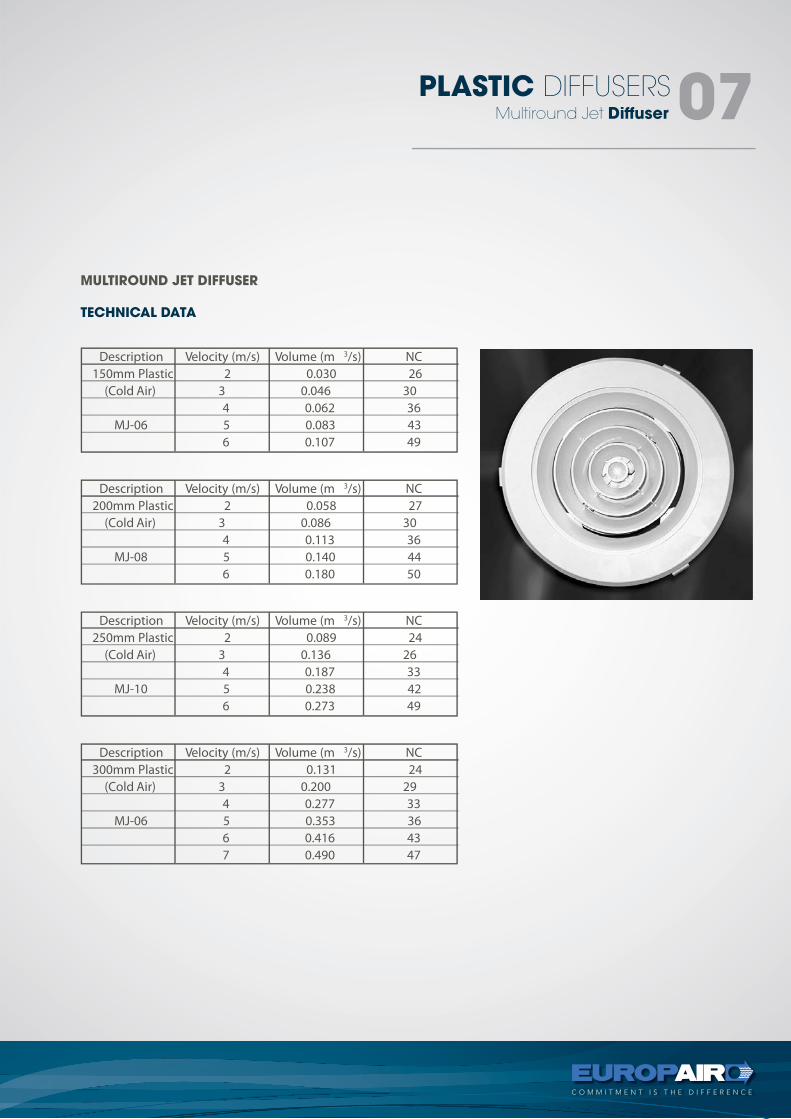
3 Description Velocity (m/s) Volume (m /s) NC 150mm Plastic 2 0.030 26 (Cold Air) 3 0.046 30 4 0.062 36
MJ-06 5 0.083 43 6 0.107 49
Description Velocity (m/s) Volume (m 3/s) NC 200mm Plastic 2 0.058 27 (Cold Air) 3 0.086 30 4 0.113 36
MJ-08 5 0.140 44 6 0.180 50
Description Velocity (m/s) Volume (m 3/s) NC 250mm Plastic 2 0.089 24 (Cold Air) 3 0.136 26 4 0.187 33
MJ-10 5 0.238 42 6 0.273 49
Description Velocity (m/s) Volume (m 3/s) NC 300mm Plastic 2 0.131 24 (Cold Air) 3 0.200 29 4 0.277 33
MJ-06 5 0.353 36 6 0.416 43 7 0.490 47
MULTIROUND JET DIFFUSER
TECHNICAL DATA
Multiround Cone Diffuser
PLASTIC DIFFUSERS 08
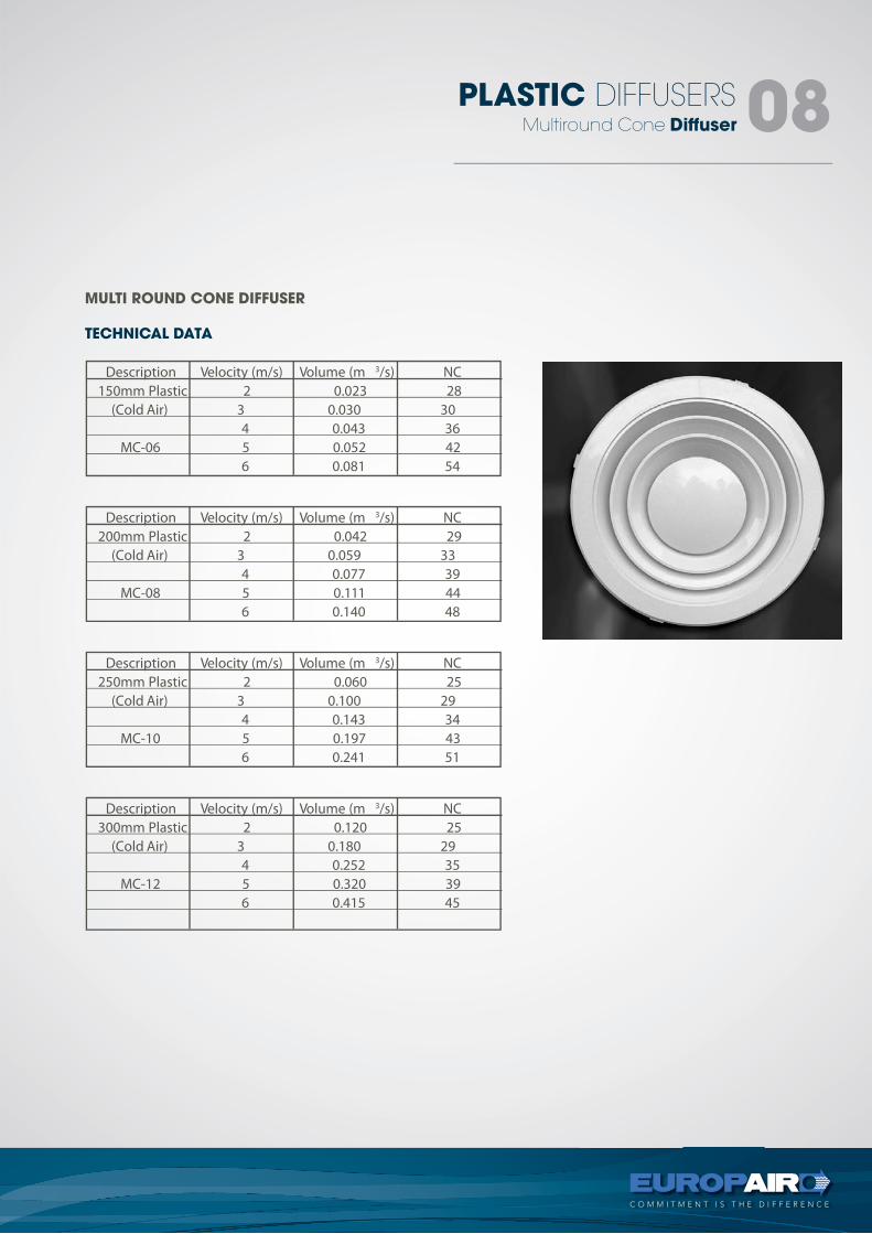
Description Velocity (m/s) Volume (m 3/s) NC 150mm Plastic 2 0.023 28 (Cold Air) 3 0.030 30 4 0.043 36
MC-06 5 0.052 42 6 0.081 54
3/s) NC Description Velocity (m/s) Volume (m 200mm Plastic 2 0.042 29 (Cold Air) 3 0.059 33 4 0.077 39
MC-08 5 0.111 44 6 0.140 48
3 Description Velocity (m/s) Volume (m /s) NC 250mm Plastic 2 0.060 25 (Cold Air) 3 0.100 29 4 0.143 34
MC-10 5 0.197 43 6 0.241 51
Description Velocity (m/s) Volume (m 3/s) NC 300mm Plastic 2 0.120 25 (Cold Air) 3 0.180 29 4 0.252 35
MC-12 5 0.320 39 6 0.415 45
MULTI ROUND CONE DIFFUSER
TECHNICAL DATA
tel +27 11 974 2425fax +27 11 974 2443web www.europair-africa.comemail: [email protected]
Europair Africa (Pty) Ltd(a div. of First Strut)
Cnr. Grader and VuurslagSpartan Ext. 3
Kempton ParkJohannesburg
METAL DIFFUSERS technical
C O M M I T M E N T I S T H E D I F F E R E N C E
T-BAR RegsiterSurface Mounted Jet Diffuser
Details
METAL DIFFUSERS 02
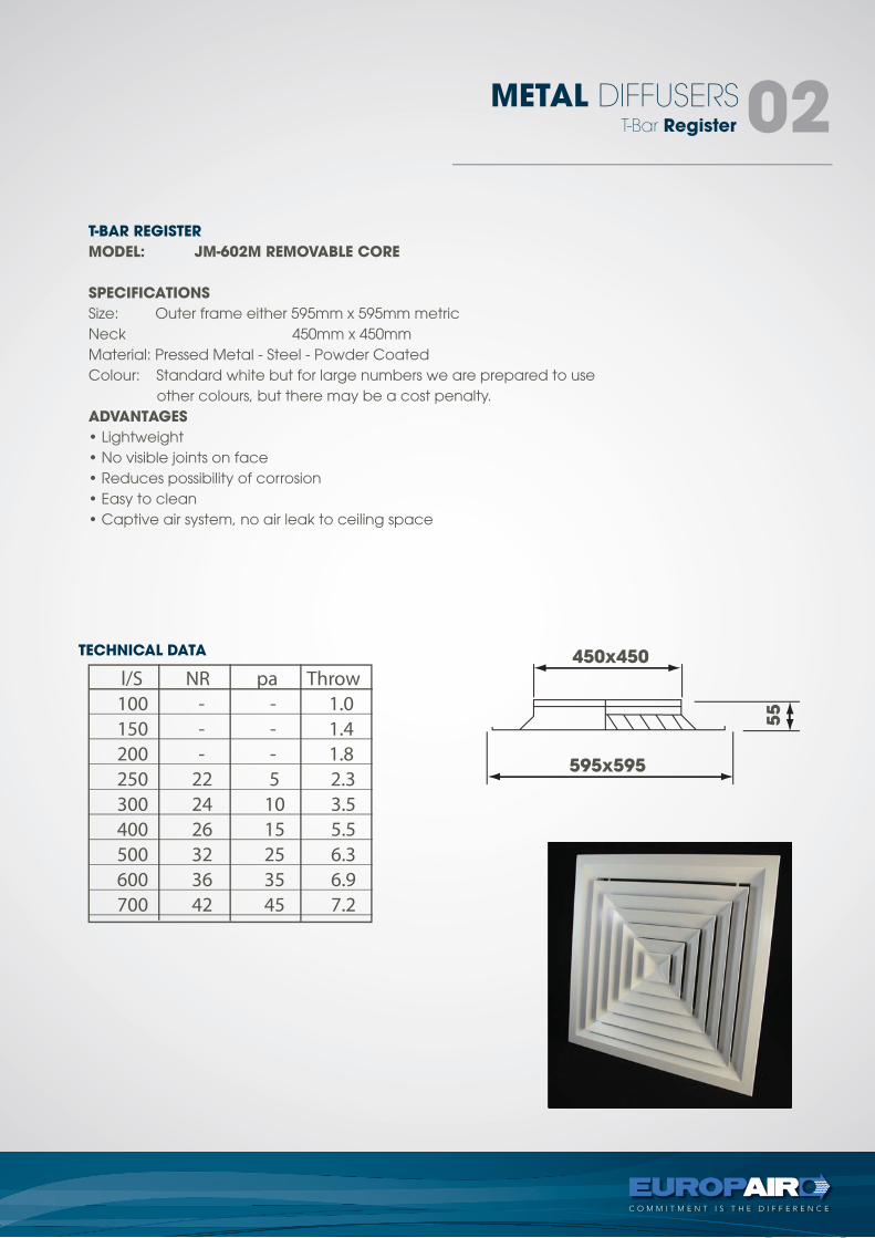
l/S NR pa Throw 100 - - 1.0 150 - - 1.4 200 - - 1.8 250 22 5 2.3 300 24 10 3.5 400 26 15 5.5 500 32 25 6.3 600 36 35 6.9 700 42 45 7.2
T-Bar Register
METAL DIFFUSERS02
l/S NR pa Throw 100 - - 1.0 150 - - 1.4 200 - - 1.8 250 22 5 2.3 300 24 10 3.5 400 26 15 5.5 500 32 25 6.3 600 36 35 6.9 700 42 45 7.2
450x450
595x59555
T-BAR REGISTER
MODEL: JM-602M REMOVABLE CORE
SPECIFICATIONS
Size: Outer frame either 595mm x 595mm metricNeck 450mm x 450mmMaterial: Pressed Metal - Steel - Powder CoatedColour: Standard white but for large numbers we are prepared to use other colours, but there may be a cost penalty.ADVANTAGES
• Lightweight• No visible joints on face• Reduces possibility of corrosion• Easy to clean• Captive air system, no air leak to ceiling space
TECHNICAL DATA
Surface Mounted Jet Diffuser
METAL DIFFUSERS 03
Volume (l/s) 64 97 129 161 194 226 259 314
Volume (l/s) 101 152 202 253 304 355 405 506
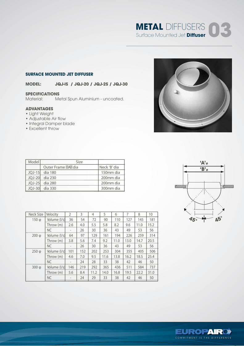
Neck Size Velocity 2 3 4 5 6 7 8 10 150 φ Volume (l/s) 36 54 72 90 110 127 145 181 Throw (m) 2.6 4.0 5.5 5.8 8.2 9.6 11.0 15.2 NC - 26 30 36 43 49 53 56 200 φ Throw (m) 3.8 5.6 7.4 9.2 11.0 13.0 14.7 20.5 NC - 26 30 36 43 49 53 56 250 φ Throw (m) 4.6 7.0 9.5 11.6 13.8 16.2 18.5 25.4 NC - 24 28 33 38 42 46 50 300 φ Volume (l/s) 146 219 292 365 436 511 584 737 Throw (m) 5.6 8.4 11.2 14.0 16.8 19.5 22.2 31.0 NC - 24 29 33 38 42 46 50
Model Size Outer Frame �A� dia Neck ‘B’ dia
aid mm051 081 aid 51-JQJ aid mm002 032 aid 02-JQJ aid mm002 082 aid 52-JQJ aid mm003 033 aid 03-JQJ
SURFACE MOUNTED JET DIFFUSER
MODEL: JQJ-lS / JQJ-20 / JQJ-2S / JQJ-30
SPECIFICATIONSMaterial: Metal Spun Aluminium - uncoated.
ADVANTAGES• Light Weight• Adjustable Air flow• Integral Damper blade• Excellent throw
‘A’Ø
‘B’Ø
45°45°
tel +27 11 974 2425fax +27 11 974 2443web www.europair-africa.comemail: [email protected]
Europair Africa (Pty) Ltd(a div. of First Strut)
Cnr. Grader and VuurslagSpartan Ext. 3
Kempton ParkJohannesburg
LINEAR AIR DIFFUSERS technical
C O M M I T M E N T I S T H E D I F F E R E N C E
types -DD, SD
tel +27 11 974 2425fax +27 11 974 2443web www.europair-africa.comemail: [email protected]
Europair Africa (Pty) Ltd(a div. of First Strut)
Cnr. Grader and VuurslagSpartan Ext. 3
Kempton ParkJohannesburg
LINEAR AIR DIFFUSERS technical
C O M M I T M E N T I S T H E D I F F E R E N C E
Sound Level - Air Supply
Details
LINEAR AIR DIFFUSERS 02Sound Level - Supply Air
LINEAR AIR DIFFUSERS 02
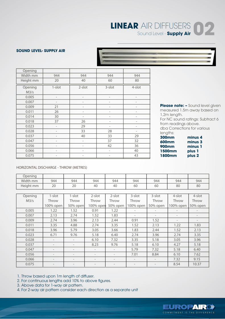
SOUND LEVEL- SUPPLY AIR
Please note: – Sound level givenmeasured 1.5m away based on1,2m length.For NC sound ratings: Subtract 6from readings above.dba Corrections for variouslengths:300mm minus 4600mm minus 3900mm minus 11500mm plus 11800mm plus 2
1. Throw based upon 1m length of diffuser.2. For continuous lengths add 10% to above figures.3. Above data for 1-way air pattern.4. For 2-way air pattern consider each direction as a separate unit
HORIZONTAL DISCHARGE - THROW (METRES)
OpeningWidth mm 944 944 944 944Height mm 20 40 60 80
Opening 1-slot 2-slot 3-slot 4-slotM3/s
0.005 - - - - 0.007 - - - - 0.009 21 - - - 0.011 26 - - - 0.014 30 - - - 0.018 37 26 - - 0.023 - 29 - - 0.028 - 33 28 - 0.037 - 40 33 29
0.047 - - 37 32 0.056 - - 42 36 0.066 - - - 40 0.075 - - - 43
OpeningWidth mm 944 944 944 944 944 944 944 944 Height mm 20 20 40 40 60 60 80 80
Opening 1-slot 1-slot 2-slot 2-slot 3-slot 3-slot 4-slot 4-slotM3/s Throw Throw Throw Throw Throw Throw Throw Throw
100% open 50% open 100% open 50% open 100% open 50% open 100% open 50% open 0.005 1.22 1.52 0.91 1.22 - - - - 0.007 2.13 2.74 1.52 1.83 - - - - 0.009 2.74 3.96 2.13 2.44 0.91 1.52 - - 0.011 3.35 4.88 2.74 3.35 1.52 2.13 1.22 1.83 0.018 3.96 5.79 3.05 3.66 1.83 2.44 1.52 2.13 0.023 6.71 9.76 5.18 6.40 2.74 3.96 2.74 3.35 0.028 - - 6.10 7.32 3.35 5.18 3.05 3.96 0.037 - - 8.23 9.76 5.18 6.10 4.27 5.18 0.047 - - - - 5.79 7.32 5.18 6.40 0.056 - - - - 7.01 8.84 6.10 7.62 0.066 - - - - - - 7.32 9.15 0.075 - - - - - - 8.54 10.37
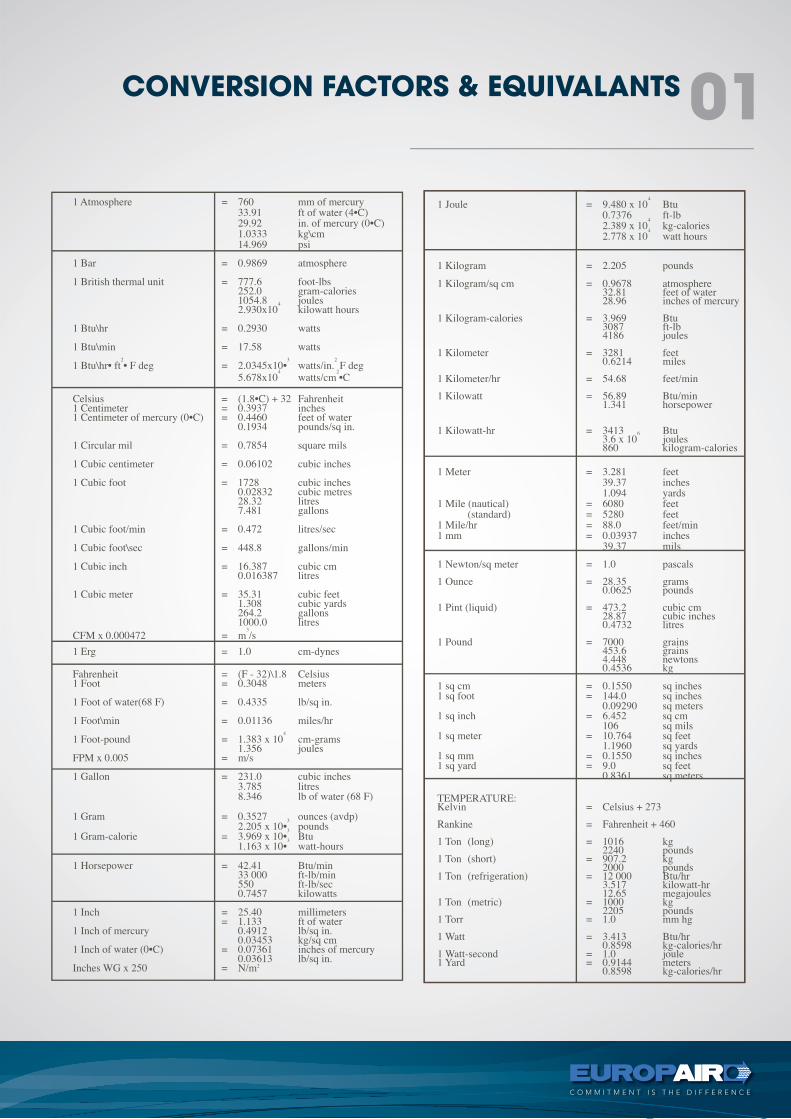
CONVERSION FACTORS & EQUIVALANTS 01