Embed Size (px)
Citation preview
230
SBN
40 °C6 ÷ 141 mm2/s20 m1 Kg/dm3
70 dB20
submersible pumps PRODUCT CATALOGUE 2014
DN150 ÷ DN300 horizontal
Applications
Construction materials
Operating limitsMaximum operating temperaturePH of treated fluidViscosity of treated fluidMaximum immersion depthDensity of treated fluidMaximum acoustic pressuremax starts per hour
Cast iron EN-GJL 250 Cast iron EN-GJL-250Stainless steel - Class A2-70 Rubber - NBR Stainless steel - AISI 420
Two silicon carbide mechanical seals (2SiC)
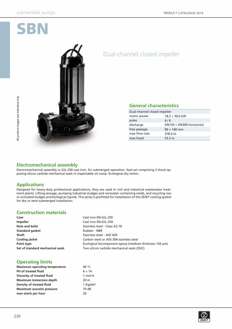
Designed for heavy-duty professional applications, they are used in civil and industrial wastewater treat-ment plants. Lifting sewage, pumping industrial sludges and rainwater containing solids, and recycling raw or activated sludges and biological liquids. This series is prefitted for installation of the ZENIT cooling system for dry or semi-submerged installation.
Electromechanical assembly in GJL-250 cast iron, for submerged operation. Seal set comprising 2 (two) op-posing silicon carbide mechanical seals in inspectable oil sump. Ecological dry motor.
CaseImpellerNuts and boltsStandard gasketShaftCooling jacket
Set of standard mechanical seals
Dual-channel closed impeller
General characteristics
Dual-channel closed impeller
Electromechanical assembly
Ecological bicomponent epoxy (medium thickness 150 μm)Paint type
motor powerpolesdischargefree passagemax flow rate
max head378.0 l/s53.2 m
18,5 ÷ 50,0 kW4 / 6
90 ÷ 140 mm
All
prod
uct i
mag
es a
re in
dica
tive
only
Carbon steel or AISI 304 stainless steel
231
SBN
submersible pumpsPRODUCT CATALOGUE 2014
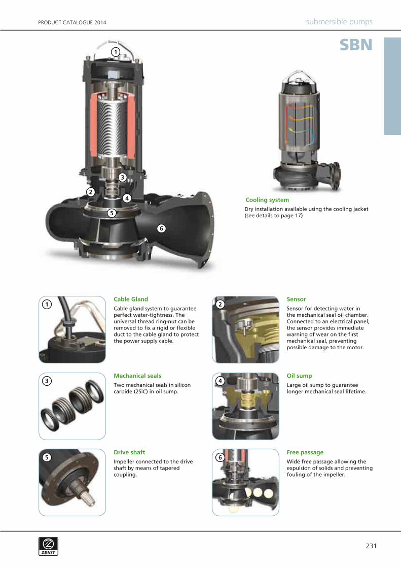
Cable Gland
Mechanical seals
Drive shaft Free passage
Sensor
Oil sump
Cable gland system to guarantee perfect water-tightness. The universal thread ring-nut can be removed to fix a rigid or flexible duct to the cable gland to protect the power supply cable.
Two mechanical seals in silicon carbide (2SiC) in oil sump.
Impeller connected to the drive shaft by means of tapered coupling.
Wide free passage allowing the expulsion of solids and preventing fouling of the impeller.
Sensor for detecting water in the mechanical seal oil chamber. Connected to an electrical panel, the sensor provides immediate warning of wear on the first mechanical seal, preventing possible damage to the motor.
Large oil sump to guarantee longer mechanical seal lifetime.
Cooling systemDry installation available using the cooling jacket (see details to page 17)
2
2
3
3
5
5
1
1
4
4
6
6
232
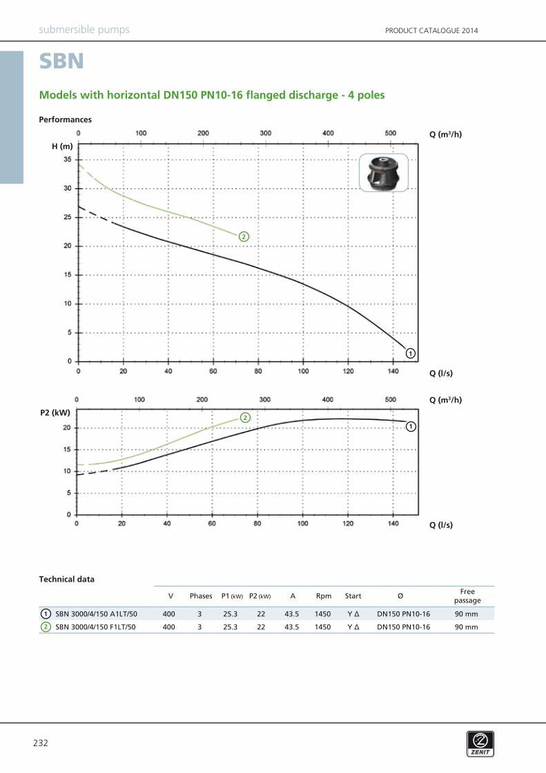
SBN 3000/4/150 A1LT/50 400 3 25.3 22 43.5 1450 Y Δ DN150 PN10-16 90 mm
SBN 3000/4/150 F1LT/50 400 3 25.3 22 43.5 1450 Y Δ DN150 PN10-16 90 mm
SBN
V P1 (kW) P2 (kW) A Rpm ØStart
submersible pumps PRODUCT CATALOGUE 2014
Performances
Technical data
Models with horizontal DN150 PN10-16 flanged discharge - 4 poles
PhasesFree
passage
2
1
Q (l/s)
Q (m3/h)H (m)
Q (l/s)
Q (m3/h)
P2 (kW)
2
12
1
233
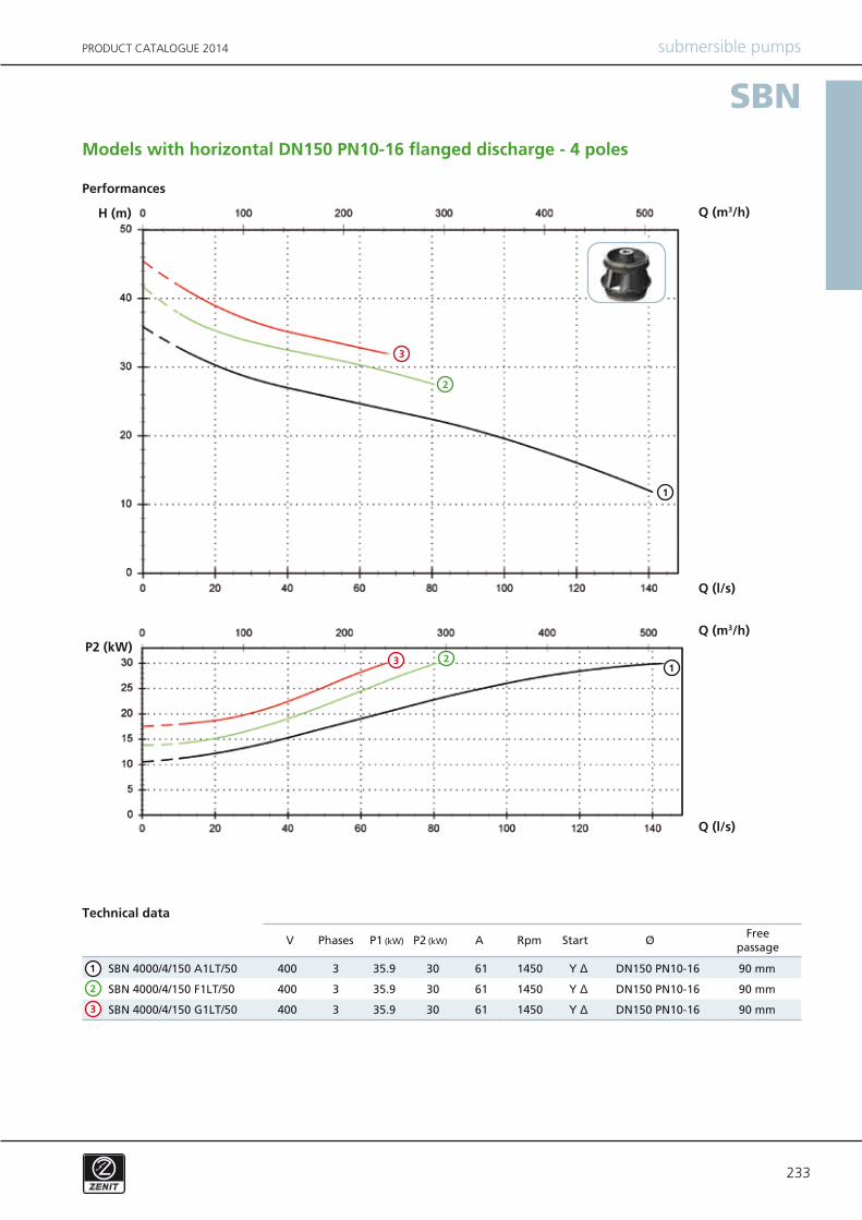
SBN 4000/4/150 A1LT/50 400 3 35.9 30 61 1450 Y Δ DN150 PN10-16 90 mm
SBN 4000/4/150 F1LT/50 400 3 35.9 30 61 1450 Y Δ DN150 PN10-16 90 mm
SBN 4000/4/150 G1LT/50 400 3 35.9 30 61 1450 Y Δ DN150 PN10-16 90 mm
SBN
V P1 (kW) P2 (kW) A Rpm ØStart
submersible pumpsPRODUCT CATALOGUE 2014
Performances
Technical data
Models with horizontal DN150 PN10-16 flanged discharge - 4 poles
PhasesFree
passage
2
1
3
2
1
3
Q (l/s)
Q (m3/h)H (m)
Q (l/s)
Q (m3/h)P2 (kW)
21
3
234
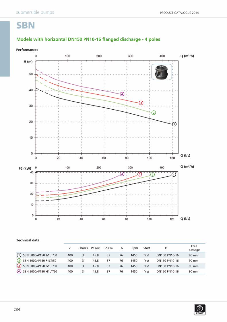
SBN 5000/4/150 A1LT/50 400 3 45.8 37 76 1450 Y Δ DN150 PN10-16 90 mm
SBN 5000/4/150 F1LT/50 400 3 45.8 37 76 1450 Y Δ DN150 PN10-16 90 mm
SBN 5000/4/150 G1LT/50 400 3 45.8 37 76 1450 Y Δ DN150 PN10-16 90 mm
SBN 5000/4/150 H1LT/50 400 3 45.8 37 76 1450 Y Δ DN150 PN10-16 90 mm4
SBN
V P1 (kW) P2 (kW) A Rpm ØStart
submersible pumps PRODUCT CATALOGUE 2014
Performances
Technical data
Models with horizontal DN150 PN10-16 flanged discharge - 4 poles
PhasesFree
passage
2
1
3
2
1
3
Q (l/s)
Q (m3/h)
H (m)
Q (l/s)
Q (m3/h)P2 (kW)
2 13
4
4
235
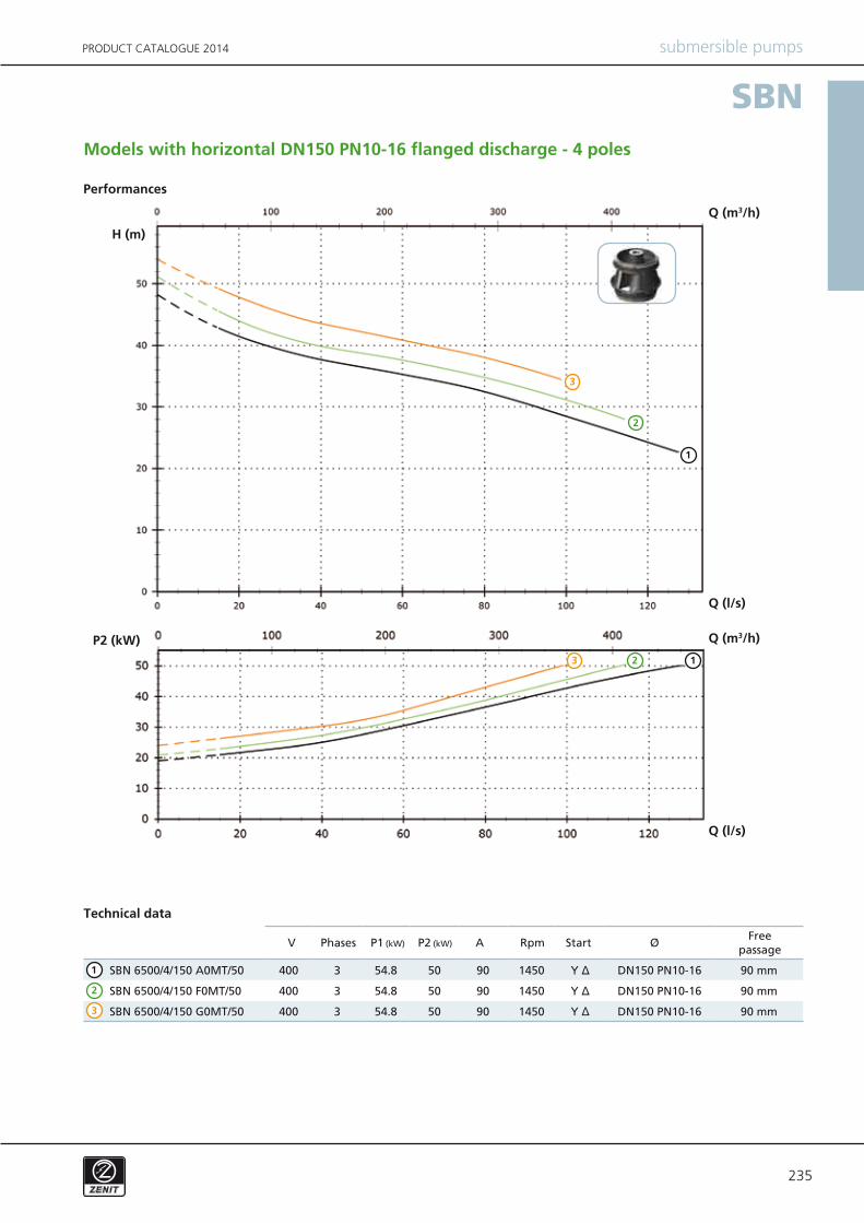
SBN 6500/4/150 A0MT/50 400 3 54.8 50 90 1450 Y Δ DN150 PN10-16 90 mm
SBN 6500/4/150 F0MT/50 400 3 54.8 50 90 1450 Y Δ DN150 PN10-16 90 mm
SBN 6500/4/150 G0MT/50 400 3 54.8 50 90 1450 Y Δ DN150 PN10-16 90 mm
SBN
V P1 (kW) P2 (kW) A Rpm ØStart
submersible pumpsPRODUCT CATALOGUE 2014
Performances
Technical data
Models with horizontal DN150 PN10-16 flanged discharge - 4 poles
PhasesFree
passage
2
1
3
2
1
3
Q (l/s)
Q (m3/h)
H (m)
Q (l/s)
Q (m3/h)P2 (kW)2 13
236
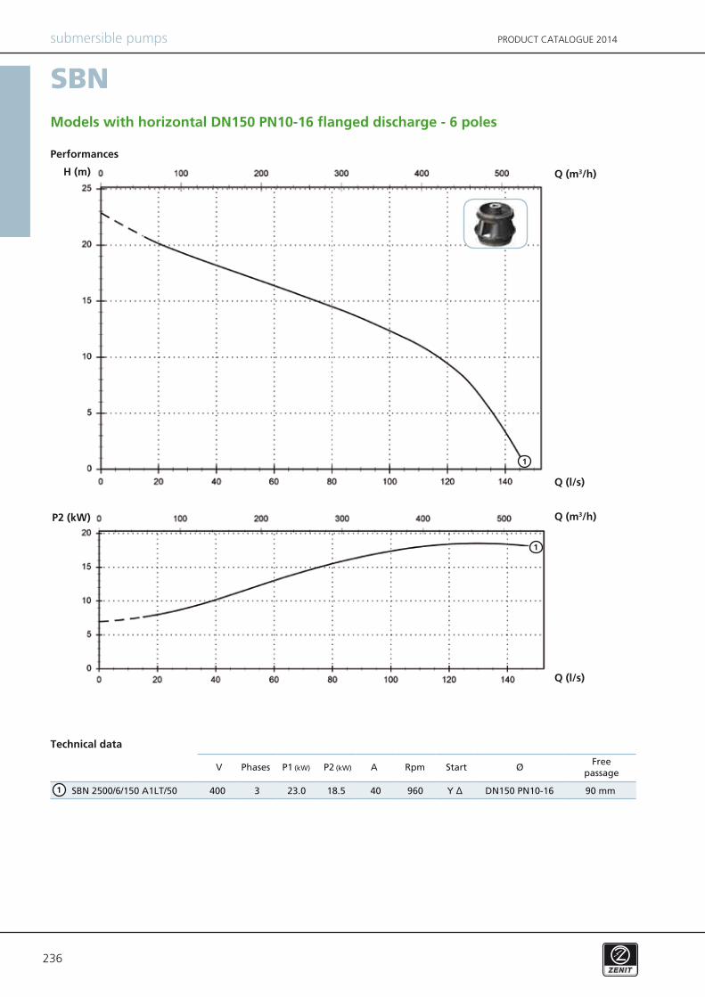
SBN 2500/6/150 A1LT/50 400 3 23.0 18.5 40 960 Y Δ DN150 PN10-16 90 mm
SBN
V P1 (kW) P2 (kW) A Rpm ØStart
submersible pumps PRODUCT CATALOGUE 2014
Performances
Technical data
Models with horizontal DN150 PN10-16 flanged discharge - 6 poles
PhasesFree
passage
1
Q (l/s)
Q (m3/h)H (m)
Q (l/s)
Q (m3/h)P2 (kW)
1
1
237
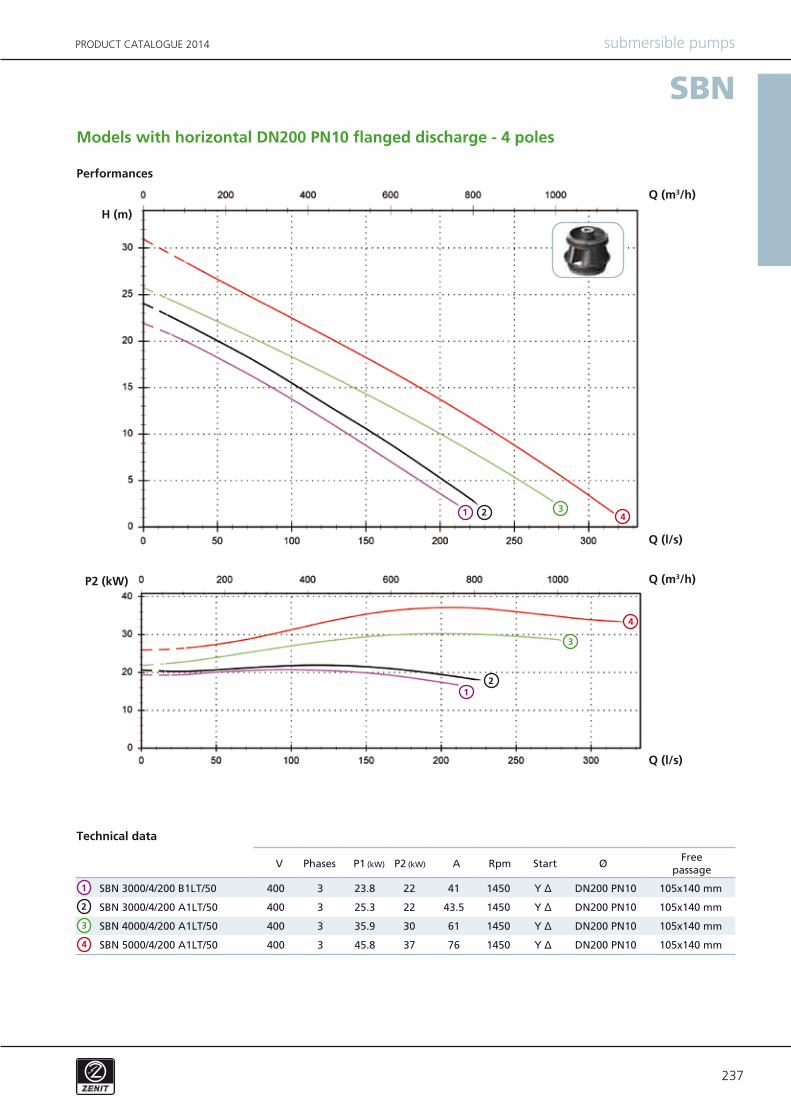
SBN 3000/4/200 B1LT/50 400 3 23.8 22 41 1450 Y Δ DN200 PN10 105x140 mm
SBN 3000/4/200 A1LT/50 400 3 25.3 22 43.5 1450 Y Δ DN200 PN10 105x140 mm
SBN 4000/4/200 A1LT/50 400 3 35.9 30 61 1450 Y Δ DN200 PN10 105x140 mm
SBN 5000/4/200 A1LT/50 400 3 45.8 37 76 1450 Y Δ DN200 PN10 105x140 mm
SBN
V P1 (kW) P2 (kW) A Rpm ØStart
submersible pumpsPRODUCT CATALOGUE 2014
Performances
Technical data
Models with horizontal DN200 PN10 flanged discharge - 4 poles
PhasesFree
passage
32 4
Q (l/s)
Q (m3/h)
H (m)
Q (l/s)
Q (m3/h)P2 (kW)
1
3
2
4
1
3
2
4
1
238
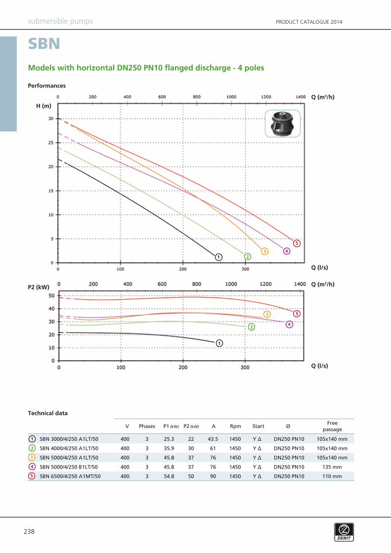
SBN 3000/4/250 A1LT/50 400 3 25.3 22 43.5 1450 Y Δ DN250 PN10 105x140 mm
SBN 4000/4/250 A1LT/50 400 3 35.9 30 61 1450 Y Δ DN250 PN10 105x140 mm
SBN 5000/4/250 A1LT/50 400 3 45.8 37 76 1450 Y Δ DN250 PN10 105x140 mm
SBN 5000/4/250 B1LT/50 400 3 45.8 37 76 1450 Y Δ DN250 PN10 135 mm
SBN 6500/4/250 A1MT/50 400 3 54.8 50 90 1450 Y Δ DN250 PN10 110 mm
SBN
V P1 (kW) P2 (kW) A Rpm ØStart
submersible pumps PRODUCT CATALOGUE 2014
Models with horizontal DN250 PN10 flanged discharge - 4 poles
Performances
Technical data
PhasesFree
passage
Q (l/s)
Q (m3/h)
H (m)
Q (l/s)
Q (m3/h)P2 (kW)
213 4
2
1
4
2
1
4
5
3 5
3
5
239
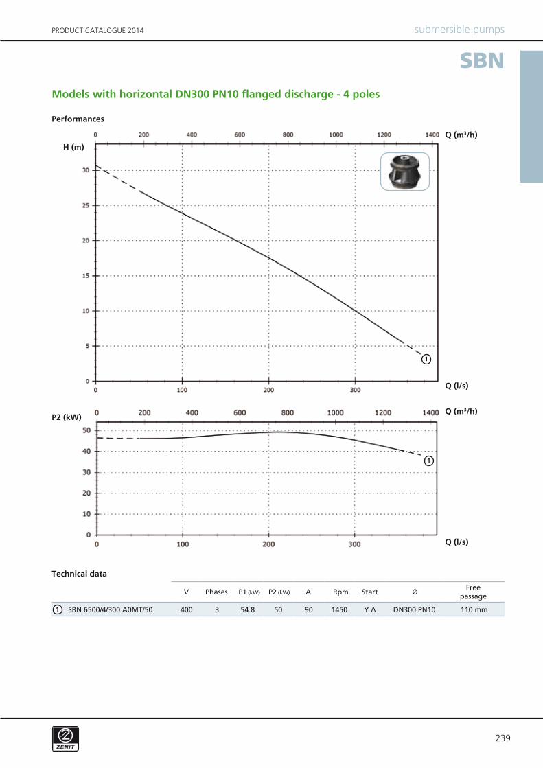
SBN 6500/4/300 A0MT/50 400 3 54.8 50 90 1450 Y Δ DN300 PN10 110 mm
SBN
V P1 (kW) P2 (kW) A Rpm ØStart
submersible pumpsPRODUCT CATALOGUE 2014
Models with horizontal DN300 PN10 flanged discharge - 4 poles
Performances
Technical data
PhasesFree
passage
Q (l/s)
Q (m3/h)
H (m)
Q (l/s)
Q (m3/h)P2 (kW)
1
1
1
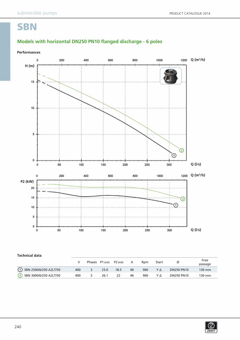
240
SBN 2500/6/250 A2LT/50 400 3 23.0 18.5 40 960 Y Δ DN250 PN10 130 mm
SBN 3000/6/250 A2LT/50 400 3 26.1 22 46 960 Y Δ DN250 PN10 130 mm
SBN
V P1 (kW) P2 (kW) A Rpm ØStart
submersible pumps PRODUCT CATALOGUE 2014
Performances
Technical data
Models with horizontal DN250 PN10 flanged discharge - 6 poles
PhasesFree
passage
2
1
Q (l/s)
Q (m3/h)
H (m)
Q (l/s)
Q (m3/h)
P2 (kW)
2
1
2
1
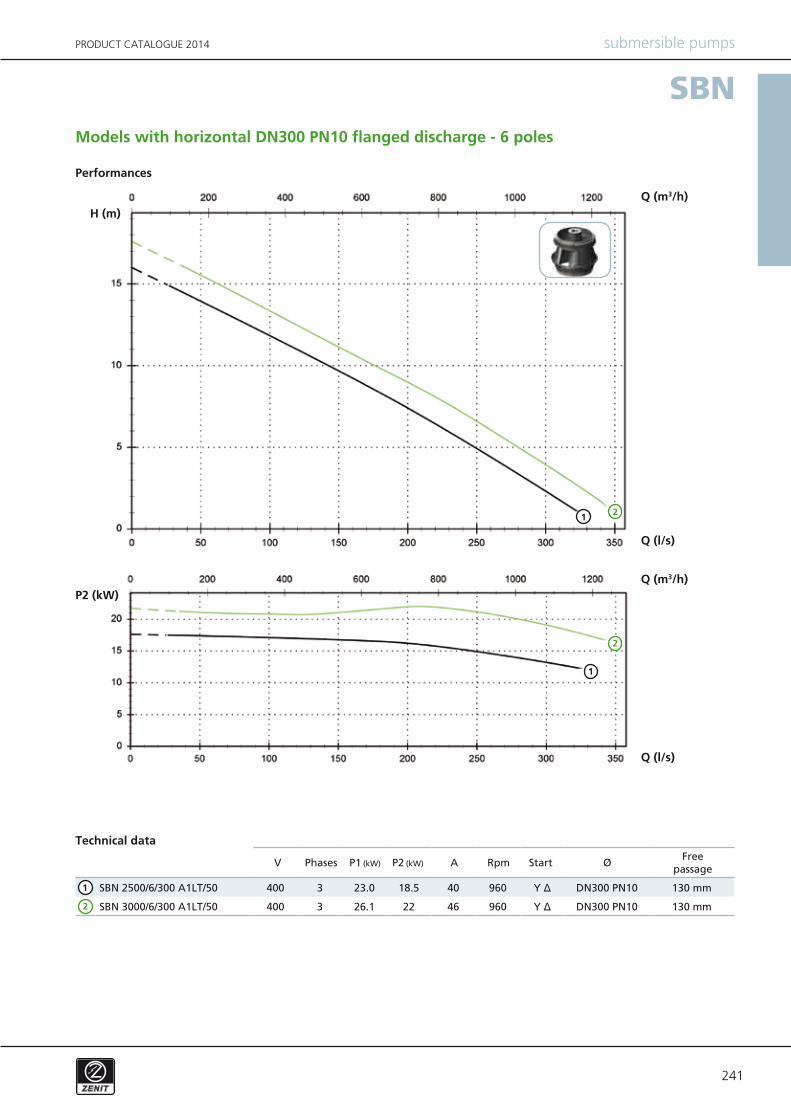
241
SBN 2500/6/300 A1LT/50 400 3 23.0 18.5 40 960 Y Δ DN300 PN10 130 mm
SBN 3000/6/300 A1LT/50 400 3 26.1 22 46 960 Y Δ DN300 PN10 130 mm
SBN
V P1 (kW) P2 (kW) A Rpm ØStart
submersible pumpsPRODUCT CATALOGUE 2014
Performances
Technical data
Models with horizontal DN300 PN10 flanged discharge - 6 poles
PhasesFree
passage
2
1
Q (l/s)
Q (m3/h)H (m)
Q (l/s)
Q (m3/h)P2 (kW)
21
2
1
242
NAE T
TC
TCD
TCDT
TCDGT
TCG
TCST
TCSGT
TS
TR
TRG
NCCCCE
FTCGFT
2SIC SICM SICAL 2SICAL
SBN 3000/4/150 A(F)1LT/50
SBN 4000/4/150 A(F)(G)1LT/50
SBN 5000/4/150 A(F)(G)(H)1LT/50
SBN 6500/4/150 A(F)(G)0MT/50
SBN 2500/6/150 A1LT/50
SBN 3000/4/200 A(B)1LT/50
SBN 4000/4/200 A1LT/50
SBN 5000/4/200 A1LT/50
SBN 3000/4/250 A1LT/50
SBN 4000/4/250 A1LT/50
SBN 5000/4/250 A(B)1LT/50
SBN 6500/4/250 A1MT/50
SBN 2500/6/250 A2LT/50
SBN 3000/6/250 A2LT/50
SBN 6500/4/300 A0MT/50
SBN 2500/6/300 A1LT/50
SBN 3000/6/300 A1LT/50
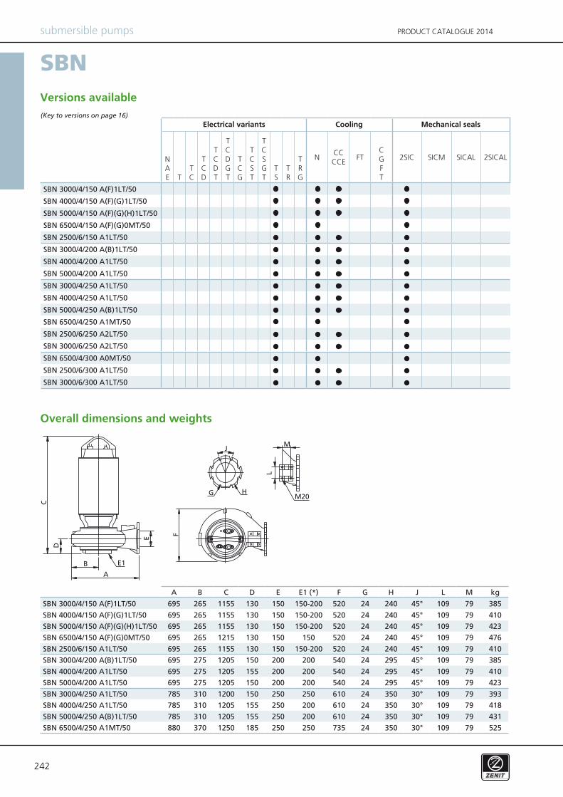
A B C D E E1 (*) F G H J L M kg
SBN 3000/4/150 A(F)1LT/50 695 265 1155 130 150 150-200 520 24 240 45° 109 79 385
SBN 4000/4/150 A(F)(G)1LT/50 695 265 1155 130 150 150-200 520 24 240 45° 109 79 410
SBN 5000/4/150 A(F)(G)(H)1LT/50 695 265 1155 130 150 150-200 520 24 240 45° 109 79 423
SBN 6500/4/150 A(F)(G)0MT/50 695 265 1215 130 150 150 520 24 240 45° 109 79 476
SBN 2500/6/150 A1LT/50 695 265 1155 130 150 150-200 520 24 240 45° 109 79 410
SBN 3000/4/200 A(B)1LT/50 695 275 1205 150 200 200 540 24 295 45° 109 79 385
SBN 4000/4/200 A1LT/50 695 275 1205 155 200 200 540 24 295 45° 109 79 410
SBN 5000/4/200 A1LT/50 695 275 1205 150 200 200 540 24 295 45° 109 79 423
SBN 3000/4/250 A1LT/50 785 310 1200 150 250 250 610 24 350 30° 109 79 393
SBN 4000/4/250 A1LT/50 785 310 1205 155 250 200 610 24 350 30° 109 79 418
SBN 5000/4/250 A(B)1LT/50 785 310 1205 155 250 200 610 24 350 30° 109 79 431
SBN 6500/4/250 A1MT/50 880 370 1250 185 250 250 735 24 350 30° 109 79 525
SBN
submersible pumps PRODUCT CATALOGUE 2014
Versions available(Key to versions on page 16)
Mechanical sealsElectrical variants Cooling
Overall dimensions and weights
243
A B C
SBN 3000/4/150 A(F)1LT/50 1080 1245 1135
SBN 4000/4/150 A(F)(G)1LT/50 1080 1245 1135
SBN 5000/4/150 A(F)(G)(H)1LT/50 1080 1245 1135
SBN 6500/4/150 A(F)(G)0MT/50 1080 1245 1135
SBN 2500/6/150 A1LT/50 1080 1245 1135
SBN 3000/4/200 A(B)1LT/50 1080 1245 1135
SBN 4000/4/200 A1LT/50 1080 1245 1135
SBN 5000/4/200 A1LT/50 1080 1245 1135
SBN 3000/4/250 A1LT/50 1080 1245 1135
SBN 4000/4/250 A1LT/50 1080 1245 1135
SBN 5000/4/250 A(B)1LT/50 1080 1245 1135
SBN 6500/4/250 A1MT/50 1080 1245 1135
SBN 2500/6/250 A2LT/50 1080 1245 1135
SBN 3000/6/250 A2LT/50 1080 1245 1135
SBN 6500/4/300 A0MT/50 1080 1245 1135
SBN 2500/6/300 A1LT/50 1080 1245 1135
SBN 3000/6/300 A1LT/50 1080 1245 1135
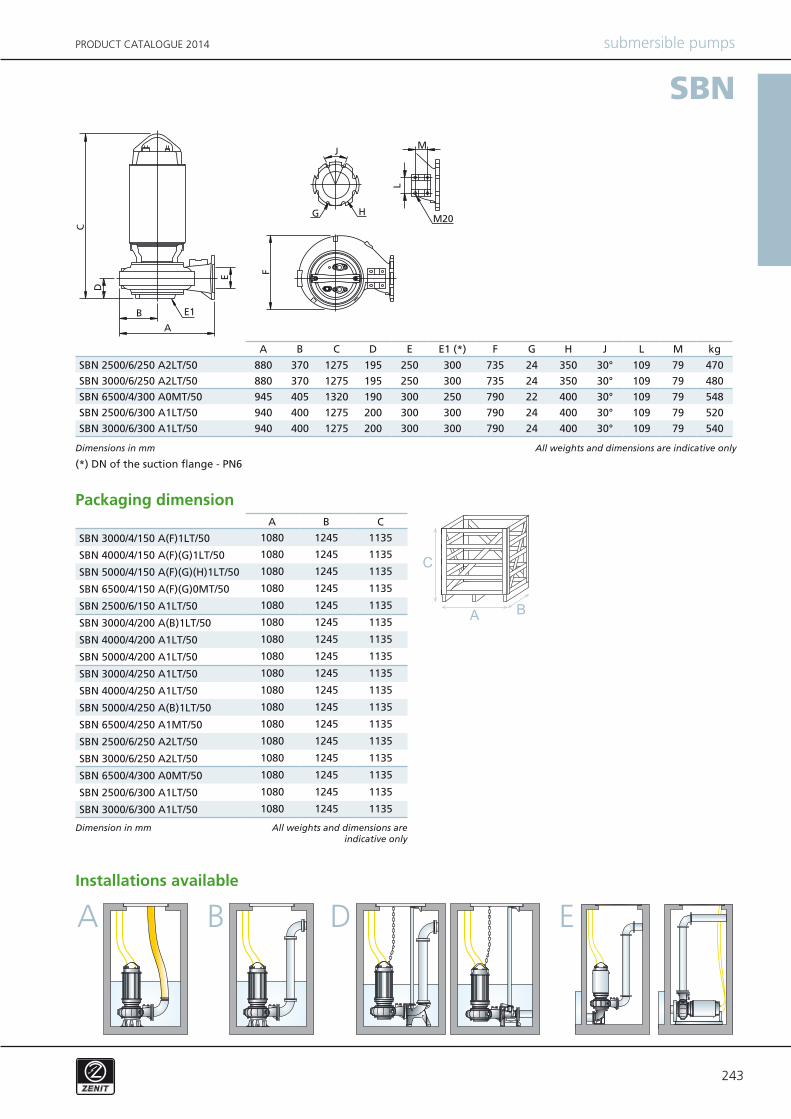
A B C D E E1 (*) F G H J L M kg
SBN 2500/6/250 A2LT/50 880 370 1275 195 250 300 735 24 350 30° 109 79 470
SBN 3000/6/250 A2LT/50 880 370 1275 195 250 300 735 24 350 30° 109 79 480
SBN 6500/4/300 A0MT/50 945 405 1320 190 300 250 790 22 400 30° 109 79 548
SBN 2500/6/300 A1LT/50 940 400 1275 200 300 300 790 24 400 30° 109 79 520
SBN 3000/6/300 A1LT/50 940 400 1275 200 300 300 790 24 400 30° 109 79 540
SBN
B D EA
submersible pumpsPRODUCT CATALOGUE 2014
Dimensions in mm
(*) DN of the suction flange - PN6
All weights and dimensions are indicative only
Packaging dimension
Dimension in mm
Installations available
All weights and dimensions are indicative only