Embed Size (px)
Citation preview
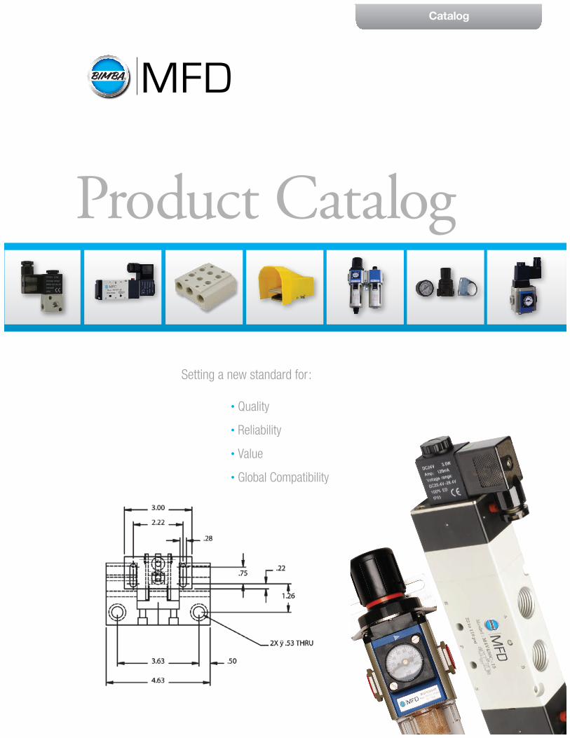
Catalog
• Quality
• Reliability
• Value
• Global Compatibility
Setting a new standard for:
Product Catalog
06
Electrical
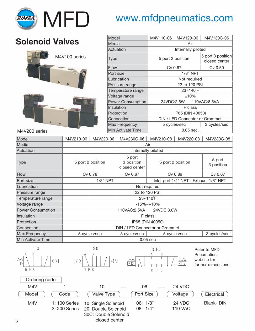
Ordering code
10: Single Solenoid20: Double Solenoid30C: Double Solenoid closed center
M4V 1: 100 Series2: 200 Series
06: 1/8"08: 1/4"
24 VDC110 VAC
Blank- DIN
M4V 1 10 24 VDC
Model Code Port SizeValve Type Voltage
Model M4V210-06 M4V220-06 M4V230C-06 M4V210-08 M4V220-08 M4V230C-08Media AirActuation Internally piloted
Type 5 port 2 position5 port
3 position closed center
5 port 2 position5 port
3 position
Flow Cv 0.78 Cv 0.67 Cv 0.89 Cv 0.67
Port size 1/8" NPT Inlet port 1/4" NPT - Exhaust 1/8" NPTLubrication Not requiredPressure range 22 to 120 PSITemperature range 23~140˚FVoltage range -15%~+10%Power Consumption 110VAC:2.5VA 24VDC:3.0WInsulation F classProtection IP65 (DIN 40050)Connection DIN / LED Connector or GrommetMax Frequency 5 cycles/sec 3 cycles/sec 5 cycles/sec 3 cycles/secMin Activate Time 0.05 sec
M4V200 series
M4V100 series
2
Refer to MFD Pneumatics’ website for further dimensions.
www.mfdpneumatics.com
Solenoid Valves Model M4V110-06 M4V120-06 M4V130C-06Media AirActuation Internally piloted
Type 5 port 2 position5 port 3 position
closed center
Flow Cv 0.67 Cv 0.50Port size 1/8” NPTLubrication Not requiredPressure range 22 to 120 PSITemperature range 23~140˚FVoltage range ±10%Power Consumption 24VDC:2.5W 110VAC:8.5VAInsulation F classProtection IP65 (DIN 40050)Connection DIN / LED Connector or GrommetMax Frequency 5 cycles/sec 3 cycles/secMin Activate Time 0.05 sec.
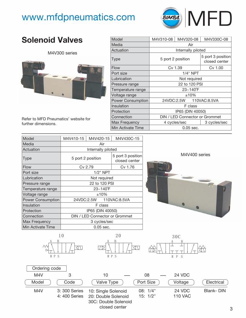
Model M4V410-15 M4V420-15 M4V430C-15Media AirActuation Internally piloted
Type 5 port 2 position5 port 3 position
closed center
Flow Cv 2.79 Cv 1.76Port size 1/2" NPTLubrication Not requiredPressure range 22 to 120 PSITemperature range 23~140˚FVoltage range ±10%Power Consumption 24VDC:2.5W 110VAC:8.5VAInsulation F classProtection IP65 (DIN 40050)Connection DIN / LED Connector or GrommetMax Frequency 3 cycles/secMin Activate Time 0.05 sec.
Model M4V310-08 M4V320-08 M4V330C-08Media AirActuation Internally piloted
Type 5 port 2 position5 port 3 position
closed center
Flow Cv 1.39 Cv 1.00Port size 1/4" NPTLubrication Not requiredPressure range 22 to 120 PSITemperature range 23~140˚FVoltage range ±10%Power Consumption 24VDC:2.5W 110VAC:8.5VAInsulation F classProtection IP65 (DIN 40050)Connection DIN / LED Connector or GrommetMax Frequency 4 cycles/sec 3 cycles/secMin Activate Time 0.05 sec.
Refer to MFD Pneumatics’ website for further dimensions.
08
3
Ordering code
10: Single Solenoid20: Double Solenoid30C: Double Solenoid closed center
M4V 3: 300 Series4: 400 Series
08: 1/4"15: 1/2"
24 VDC110 VAC
Blank- DIN
M4V 3 10 24 VDC
Model Code Port SizeValve Type Voltage Electrical
M4V300 series
M4V400 series
Solenoid Valves
www.mfdpneumatics.com
Product Brief
Leaders in Actuation.
Mead Fluid DynamicsChicago, IL 60641Telephone: 773-685-6800Fax: 773-685-7002Email: [email protected] www.mead-usa.com
To learn more about this product, scan this QR code
with your mobile device.
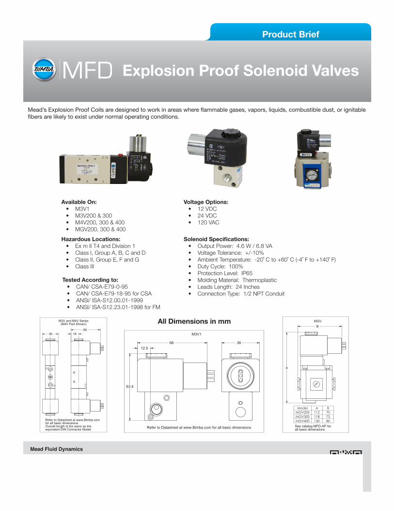
Explosion Proof Solenoid Valves
All Dimensions in mm 18
66
equivalent DIN Connector Model Overall length is the same as the
Refer to Datasheet at www.Bimba.com for all basic dimensions
M3V and M4V Series(M4V Part Shown)
FINISH:
ER No.
CONCENTRICITY
PERPEND.± 1
UNLESS OTHERWISE SPECIFIED
(FRACTIONS) ±1/64
MATERIAL & SPECIFICATION
TITLE:64
PARALLELISM
FLATNESS
RUN OUT
THE WRITTEN PERMISSION OF MEAD FLUID DYNAMICS IS PROHIBITED.
ROUNDNESS
THE INFORMATION CONTAINED IN THIS DRAWING IS THE SOLE PROPERTY OF
DO NOT SCALE
OF 1
SCALE:
DES: DR:
BY
DIMENSION
AP: DATE:
DWG. NO.
A
SHEET 1
DRAWINGSOLIDWORKS
SIZEDWG
CRITICAL ♦{ # }INSPECTION NO.
DATE
DWG. NO.
DIMENSION
REV No.
SURFACEFINISH
ANGLES
MEAD FLUID DYNAMICS
(DECIMAL).xxx = ±.005 .xx = ±.010TOLERANCES:
DIMENSIONS ARE IN INCHES.
MEAD FLUID DYNAMICS. ANY REPRODUCTION IN PART OR WHOLE WITHOUT
36 M3V1
REV No.DO NOT SCALE DATE
A
OF 1
SCALE:
CONCENTRICITY
RUN OUT
(FRACTIONS) ±1/64
MATERIAL & SPECIFICATION
TITLE:
THE INFORMATION CONTAINED IN THIS DRAWING IS THE SOLE PROPERTY OF
ER No. BY
PARALLELISM
SHEET 1
PERPEND.
MEAD FLUID DYNAMICS64
± 1
MEAD FLUID DYNAMICS. ANY REPRODUCTION IN PART OR WHOLE WITHOUTTHE WRITTEN PERMISSION OF MEAD FLUID DYNAMICS IS PROHIBITED.
SURFACE
INSPECTION NO.
DES: DR: AP:
(DECIMAL).xxx = ±.005 .xx = ±.010
DWG. NO.
DATE:
DWG. NO.
SOLIDWORKS
DIMENSION
DRAWING
DWGSIZE
TOLERANCES:DIMENSIONS ARE IN INCHES.
UNLESS OTHERWISE SPECIFIED♦{ # }
FINISH:
DIMENSION
CRITICAL
FINISH
ANGLES
ROUNDNESS
FLATNESS
36
Refer to Datasheet at www.Bimba.com for all basic dimensions
63.4
66 12.5
Available On:• M3V1• M3V200 & 300• M4V200, 300 & 400• MGV200, 300 & 400
Voltage Options:• 12 VDC• 24 VDC• 120 VAC
Solenoid Specifications:• Output Power: 4.6 W / 6.8 VA• Voltage Tolerance: +/-10% • Ambient Temperature: -20˚ C to +60˚ C (-4˚ F to +140˚ F)• Duty Cycle: 100%• Protection Level: IP65• Molding Material: Thermoplastic• Leads Length: 24 Inches• Connection Type: 1/2 NPT Conduit
Hazardous Locations:• Ex m II T4 and Division 1• Class I, Group A, B, C and D• Class II, Group E, F and G• Class III
Tested According to:• CAN/ CSA-E79-0-95• CAN/ CSA-E79-18-95 for CSA• ANSI/ ISA-S12.00.01-1999• ANSI/ ISA-S12.23.01-1998 for FM
Mead’s Explosion Proof Coils are designed to work in areas where flammable gases, vapors, liquids, combustible dust, or ignitable fibers are likely to exist under normal operating conditions.
MFD-EPS-1213
See catalog MFD-AP for all basic dimensions
Model A BMGV200 112 70MGV300 118 73MGV400 130 80
MGV
DATE
CONCENTRICITY
PERPEND.
RUN OUTFINISH
THE WRITTEN PERMISSION OF MEAD FLUID DYNAMICS IS PROHIBITED.
TITLE:
UNLESS OTHERWISE SPECIFIED
(FRACTIONS) ±1/64PARALLELISM
FLATNESS
± 1
64
THE INFORMATION CONTAINED IN THIS DRAWING IS THE SOLE PROPERTY OF
ROUNDNESS
ANGLES
MATERIAL & SPECIFICATION
DWG. NO.
DIMENSION
DRAWING
DWG
OF 1
SCALE:
DES: DR: AP:
SOLIDWORKS
SIZE A
DATE:
DWG. NO.
SHEET 1
DIMENSIONINSPECTION NO.
CRITICAL
ER No. BY
♦{ # }
FINISH:
DO NOT SCALE REV No.
SURFACEMEAD FLUID DYNAMICS
(DECIMAL).xxx = ±.005 .xx = ±.010TOLERANCES:
DIMENSIONS ARE IN INCHES.
MEAD FLUID DYNAMICS. ANY REPRODUCTION IN PART OR WHOLE WITHOUT
A
B
Leaders in Actuation.
Worldwide distribution means there is a professional stocking Bimba distributor nearby ready to service your needs.
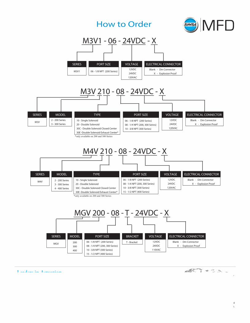
How to Order
MGV 200 - 08 - T - 24VDC - X
200
300
400
MODEL
06 - 1/8 NPT (200 Series)
08 - 1/4 NPT (200, 300 Series)
10 - 3/8 NPT (300 Series)
15 - 1/2 NPT (400 Series)
PORT SIZE
MGV
SERIES
T - Bracket
BRACKET
12VDC
24VDC
110VAC
VOLTAGE
Blank - Din Connector
X - Explosion Proof
ELECTRICAL CONNECTOR
Mead Fluid DynamicsChicago, IL 60641Telephone: 773-685-6800Fax: 773-685-7002Email: [email protected] www.mead-usa.com
M3V 210 - 08 - 24VDC - X
2 - 200 Series
3 - 300 Series
MODEL
M3V
SERIES
12VDC
24VDC
120VAC
VOLTAGE
Blank - Din Connector
X - Explosion Proof
ELECTRICAL CONNECTOR
10 - Single Solenoid
20 - Double Solenoid
30C - Double Solenoid Closed Center
30E -Double Solenoid Exhaust Center*
TYPE
06 - 1/8 NPT (200 Series)
08 - 1/4 NPT (200, 300 Seires)
10 - 3/8 NPT (300 Series)
PORT SIZE
*only available on 200 and 300 Series
M3V1 - 06 - 24VDC - X
06 - 1/8 NPT (200 Series)
PORT SIZE
Blank - Din Connector
X - Explosion Proof
ELECTRICAL CONNECTOR
12VDC
24VDC
120VAC
VOLTAGE
M3V1
SERIES
M4V 210 - 08 - 24VDC - X
2 - 200 Series
3 - 300 Series
4 - 400 Series
MODEL
10 - Single Solenoid
20 - Double Solenoid
30C - Double Solenoid Closed Center
30E -Double Solenoid Exhaust Center*
TYPE
M4V
SERIES
06 - 1/8 NPT (200 Series)
08 - 1/4 NPT (200, 300 Series)
10 - 3/8 NPT (300 Series)
15 - 1/2 NPT (400 Series)
PORT SIZE
12VDC
24VDC
120VAC
VOLTAGE
Blank - Din Connector
X - Explosion Proof
ELECTRICAL CONNECTOR
*only available on 200 and 300 Series
06
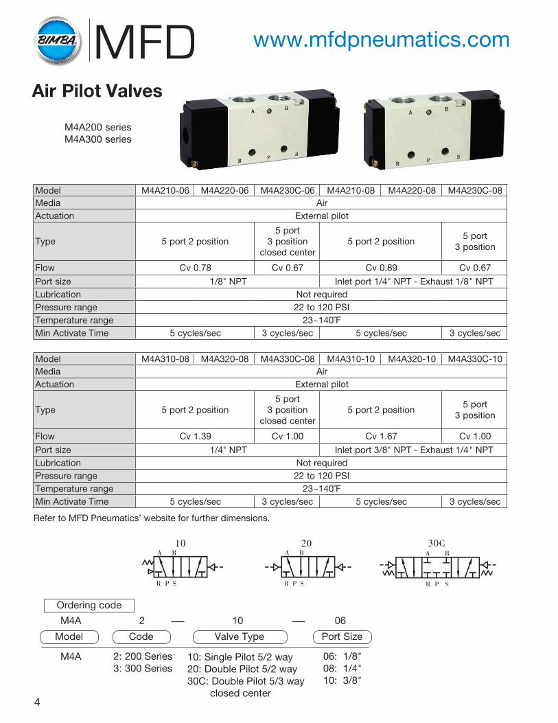
Ordering code
M4A 2: 200 Series3: 300 Series
06: 1/8"08: 1/4"10: 3/8"
10: Single Pilot 5/2 way20: Double Pilot 5/2 way30C: Double Pilot 5/3 way closed center
M4A 2 10
Model Code Port SizeValve Type
M4A200 seriesM4A300 series
4
Refer to MFD Pneumatics’ website for further dimensions.
Air Pilot Valves
Model M4A210-06 M4A220-06 M4A230C-06 M4A210-08 M4A220-08 M4A230C-08Media AirActuation External pilot
Type 5 port 2 position5 port
3 position closed center
5 port 2 position5 port
3 position
Flow Cv 0.78 Cv 0.67 Cv 0.89 Cv 0.67
Port size 1/8" NPT Inlet port 1/4" NPT - Exhaust 1/8" NPTLubrication Not requiredPressure range 22 to 120 PSITemperature range 23~140˚FMin Activate Time 5 cycles/sec 3 cycles/sec 5 cycles/sec 3 cycles/sec
Model M4A310-08 M4A320-08 M4A330C-08 M4A310-10 M4A320-10 M4A330C-10Media AirActuation External pilot
Type 5 port 2 position5 port
3 position closed center
5 port 2 position5 port
3 position
Flow Cv 1.39 Cv 1.00 Cv 1.67 Cv 1.00
Port size 1/4" NPT Inlet port 3/8" NPT - Exhaust 1/4" NPTLubrication Not requiredPressure range 22 to 120 PSITemperature range 23~140˚FMin Activate Time 5 cycles/sec 3 cycles/sec 5 cycles/sec 3 cycles/sec
www.mfdpneumatics.com
5
Ordering code
M100M
M100M: 100 Series ValveM200M: 200 Series ValveM300M: 300 Series ValveM400M: 400 Series Valve
2F
M100M: 2F to 8F Stations*M200M: 2F to 8F Stations*M300M: 2F to 8F Stations*M400M: 2F to 8F Stations*
Model Number of Stations
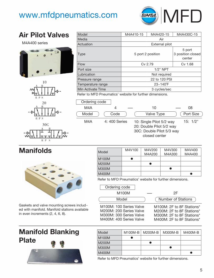
M4A400 series
Refer to MFD Pneumatics’ website for further dimensions.
Refer to MFD Pneumatics’ website for further dimensions.
Refer to MFD Pneumatics’ website for further dimensions.
Gaskets and valve mounting screws includ-ed with manifold. Manifold stations available in even increments (2, 4, 6, 8).
Air Pilot Valves
Manifolds
Manifold Blanking Plate
Model M4A410-15 M4A420-15 M4A430C-15Media AirActuation External pilot
Type 5 port 2 position5 port
3 position closed center
Flow Cv 2.79 Cv 1.68
Port size 1/2" NPTLubrication Not requiredPressure range 22 to 120 PSITemperature range 23~140˚FMin Activate Time 3 cycles/sec
ModelM4V100 M4V200
M4A200M4V300M4A300
M4V400M4A400
M100MM200MM300MM400M
•
•• •
Model M100M-B M200M-B M300M-B M400M-B
M100MM200MM300MM400M
•
•• •
Ordering code
M4A 4: 400 Series 15: 1/2"10: Single Pilot 5/2 way20: Double Pilot 5/2 way30C: Double Pilot 5/3 way closed center
08M4A 4 10
Model Code Port SizeValve Type
www.mfdpneumatics.com
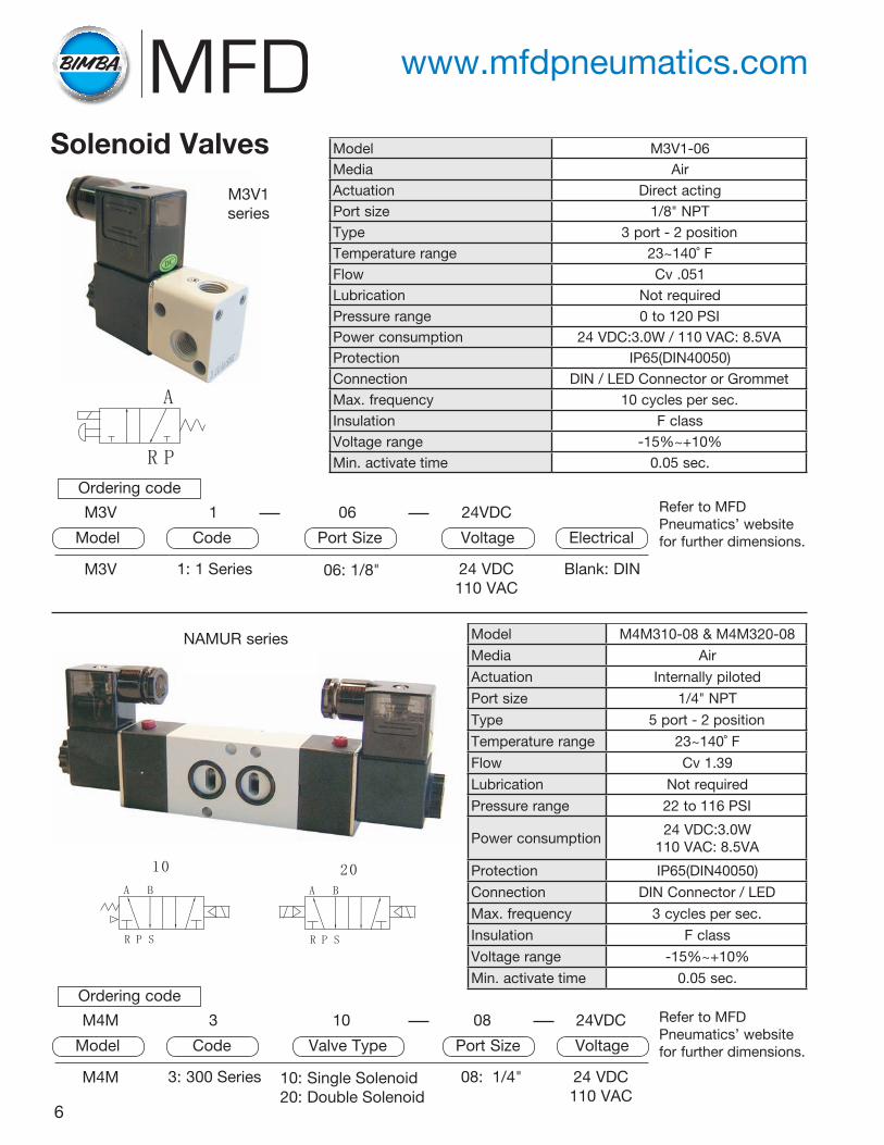
Model M3V1-06Media AirActuation Direct actingPort size 1/8" NPTType 3 port - 2 positionTemperature range 23~140˚ FFlow Cv .051Lubrication Not requiredPressure range 0 to 120 PSIPower consumption 24 VDC:3.0W / 110 VAC: 8.5VAProtection IP65(DIN40050)Connection DIN / LED Connector or GrommetMax. frequency 10 cycles per sec.Insulation F classVoltage range -15%~+10%Min. activate time 0.05 sec.
Model M4M310-08 & M4M320-08
Media Air
Actuation Internally piloted
Port size 1/4" NPT
Type 5 port - 2 position
Temperature range 23~140˚ F
Flow Cv 1.39
Lubrication Not required
Pressure range 22 to 116 PSI
Power consumption24 VDC:3.0W
110 VAC: 8.5VA
Protection IP65(DIN40050)
Connection DIN Connector / LED
Max. frequency 3 cycles per sec.
Insulation F class
Voltage range -15%~+10%
Min. activate time 0.05 sec.
NAMUR series
6
Solenoid Valves
24 VDC110 VAC
Blank: DIN
24VDC
Voltage Electrical
M3V 1: 1 Series 06: 1/8"
M3V 1 06
Model Code Port Size
24 VDC110 VAC
08 24VDC
Voltage
Ordering code
M4M 3: 300 Series 08: 1/4"10: Single Solenoid20: Double Solenoid
M4M 3 10
Model Code Port SizeValve Type
M3V1 series
Refer to MFD Pneumatics’ website for further dimensions.
Refer to MFD Pneumatics’ website for further dimensions.
www.mfdpneumatics.com
Ordering code
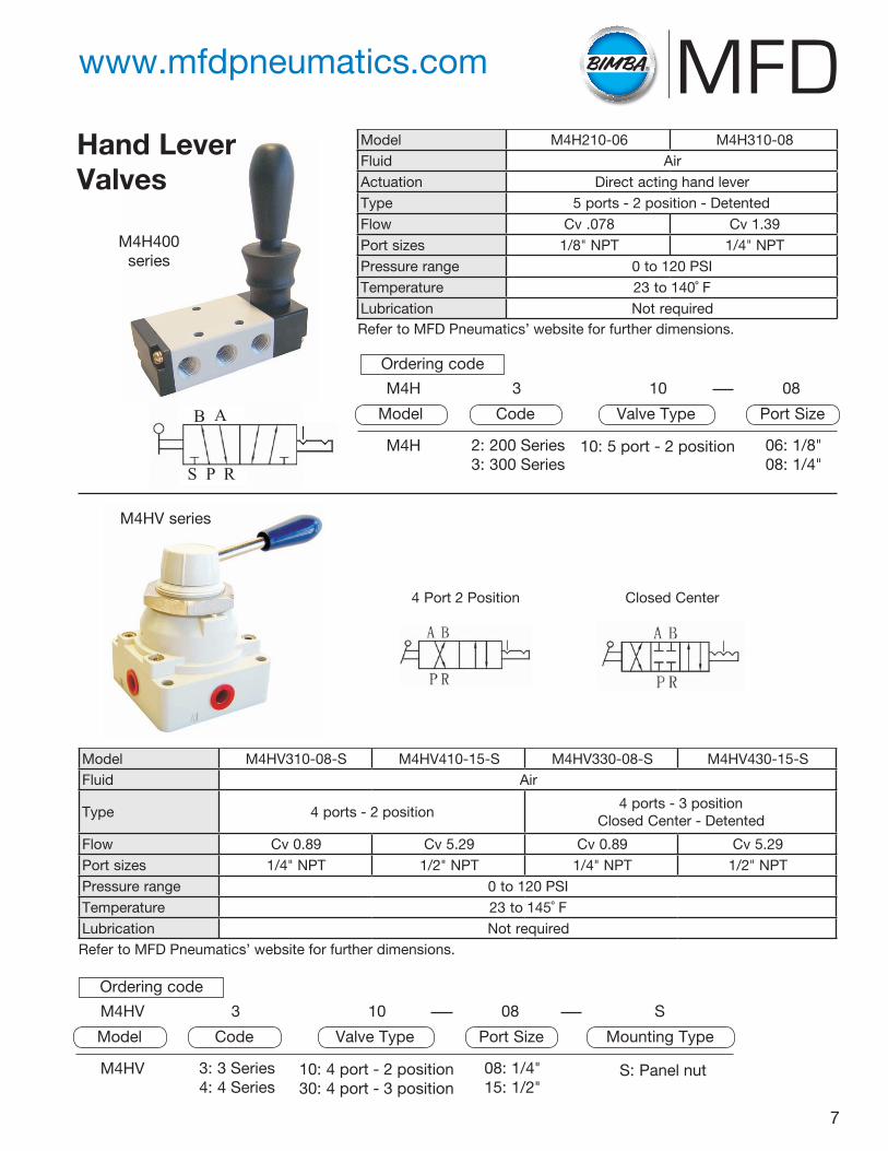
Model M4H210-06 M4H310-08Fluid AirActuation Direct acting hand leverType 5 ports - 2 position - DetentedFlow Cv .078 Cv 1.39Port sizes 1/8" NPT 1/4" NPTPressure range 0 to 120 PSITemperature 23 to 140˚ FLubrication Not required
Hand Lever Valves
Refer to MFD Pneumatics’ website for further dimensions.
06: 1/8"08: 1/4"
08
Port Size
Ordering code
M4H 2: 200 Series3: 300 Series
10: 5 port - 2 position
M4H 3 10
Model Code Valve Type
Model M4HV310-08-S M4HV410-15-S M4HV330-08-S M4HV430-15-SFluid Air
Type 4 ports - 2 position4 ports - 3 position
Closed Center - Detented
Flow Cv 0.89 Cv 5.29 Cv 0.89 Cv 5.29Port sizes 1/4" NPT 1/2" NPT 1/4" NPT 1/2" NPTPressure range 0 to 120 PSITemperature 23 to 145˚ FLubrication Not requiredRefer to MFD Pneumatics’ website for further dimensions.
S: Panel nut
S
Mounting Type
08: 1/4"15: 1/2"
08
Port Size
Ordering code
M4HV 3: 3 Series4: 4 Series
10: 4 port - 2 position30: 4 port - 3 position
M4HV 3 10
Model Code Valve Type
M4H400 series
M4HV series
7
4 Port 2 Position Closed Center
www.mfdpneumatics.com
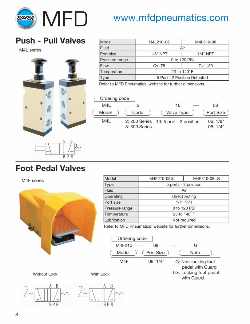
M4L series
Push - Pull Valves
Foot Pedal Valves
Model M4L210-06 M4L310-08Fluid AirPort size 1/8" NPT 1/4" NPTPressure range 0 to 120 PSIFlow Cv .78 Cv 1.39Temperature 23 to 140˚ FType 5 Port - 2 Position Detented
Refer to MFD Pneumatics’ website for further dimensions.
M4F series Model M4F210-08G M4F310-08LGType 5 ports - 2 positionFluid AirOperating Direct ActingPort size 1/4" NPTPressure range 0 to 120 PSITemperature 23 to 140˚ FLubrication Not required
Refer to MFD Pneumatics’ website for further dimensions.
06: 1/8"08: 1/4"
08
Port Size
Ordering code
M4L 2: 200 Series3: 300 Series
10: 5 port - 2 position
M4L 2 10
Model Code Valve Type
Ordering code
M4F 08: 1/4" G: Non-locking foot pedal with GuardLG: Locking foot pedal with Guard
M4F210 08 G
Model Port Size Note
8
Without Lock With Lock
www.mfdpneumatics.com
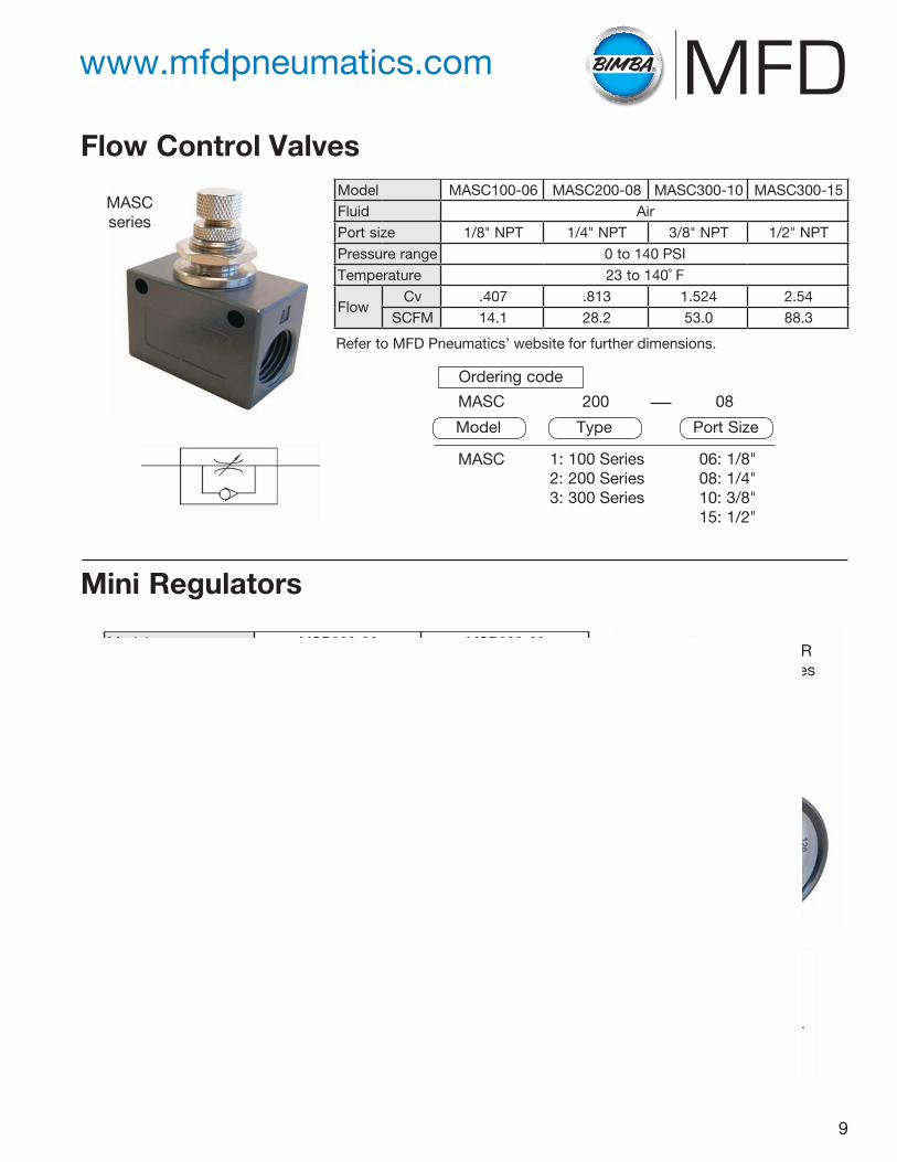
Model MASC100-06 MASC200-08 MASC300-10 MASC300-15Fluid AirPort size 1/8" NPT 1/4" NPT 3/8" NPT 1/2" NPTPressure range 0 to 140 PSITemperature 23 to 140˚ F
FlowCv .407 .813 1.524 2.54
SCFM 14.1 28.2 53.0 88.3
Flow Control Valves
Mini Regulators
06: 1/8"08: 1/4"10: 3/8"15: 1/2"
08
Port Size
Ordering code
MASC 1: 100 Series2: 200 Series3: 300 Series
MASC 200
Model Type
MASC series
Refer to MFD Pneumatics’ website for further dimensions.
Model MSR200-06 MSR200-08Fluid AirPort Size 1/8" NPT 1/4" NPTPressure range 8 to 140 PSIMax. Pressure 145 PSITemperature 23 to 140˚ FType Relieving / Press to lock adjustable knobBody Material AluminumIncludes Gauge / Bracket / Nut / 2 Gauge Ports
06: 1/8"08: 1/4"
08
Port Size
Ordering code
MSR 200: 200 Series
MSR 200
Model Type
Refer to MFD Pneumatics’ website for further dimensions.
MSR series
9
www.mfdpneumatics.com
Performance Data
0102030405060708090
0 20 40 60 80 100 120
OutletPressure(psi)
Flow (SCFM)
MGF200
0102030405060708090100
0 50 100 150 200
OutletPressure(psi)
Flow (SCFM)
MGF300
0102030405060708090100
0 50 100 150 200 250 300
OutletPressure(psi)
Flow (SCFM)
MGF400
0102030405060708090100
0 100 200 300 400 500
OutletPressure(psi)
Flow (SCFM)
MGF600
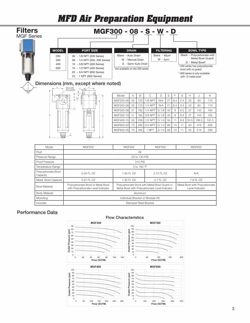
MGF SeriesFilters
Flow Characteristics
Model A B C D E F G H J K
MGF200-06 30 123 1/8 NPT N/A 27 8.4 5.4 23 93 110
MGF200-08 30 123 1/4 NPT N/A 27 8.4 5.4 23 93 110
MGF300-08 41 182 1/4 NPT G 1/8 40 8 6.5 27 143 164
MGF300-10 41 182 3/8 NPT G 1/8 40 8 6.5 27 143 164
MGF400-15 50 208 1/2 NPT G 1/4 55 11 8.6 33.5 166.5 191.5
MGF600-20 70 280 3/4 NPT G 1/4 66 13 11 50 219 256
MGF600-25 70 280 1 NPT G 1/4 66 13 11 50 219 256
Dimensions (mm, except where noted)E
F
H
J
G
K
D
A
B
C
BRACKETINCLUDED
Model MGF200 MGF300 MGF400 MGF600
Fluid Air
Pressure Range 20 to 130 PSI
Proof Pressure 215 PSI
Temperature Range 0 to 160 °F
Polycarbonate BowlCapacity
0.34 FL OZ 1.35 FL OZ 2.72 FL OZ N/A
Metal Bowl Capacity 0.57 FL OZ 1.35 FL OZ 2.7 FL OZ 7.8 FL OZ
Bowl MaterialPolycarbonate Bowl or Metal Bowlwith Polycarbonate Level Indicator
Polycarbonate Bowl with Metal Bowl Guard orMetal Bowl with Polycarbonate Level Indicator
Metal Bowl with PolycarbonateLevel Indicator
Body Material Aluminum
Mounting Individual Bracket or Modular Kit
Includes Stamped Steel Bracket
MFD Air Preparation EquipmentMGF300 - 08 - S - W - D
200
300
400
600
MODEL
06 - 1/8 NPT (200 Series)
08 - 1/4 NPT (200, 300 Series)
10 - 3/8 NPT (300 Series)
15 - 1/2 NPT (400 Series)
20 - 3/4 NPT (600 Series)
25 - 1 NPT (600 Series)
PORT SIZE DRAIN
Blank - 40µm
W - 5µm
FILTERINGBlank - Polycarbonate with
Metal Bowl Guard2
D - Metal Bowl3
BOWL TYPE
2-200 series has polycarbonatebowl with no guard
3-600 series is only availablewith -D metal bowl
1not available on the 200 series
Blank - Auto Drain1
M - Manual Drain
S - Semi-Auto Drain
3
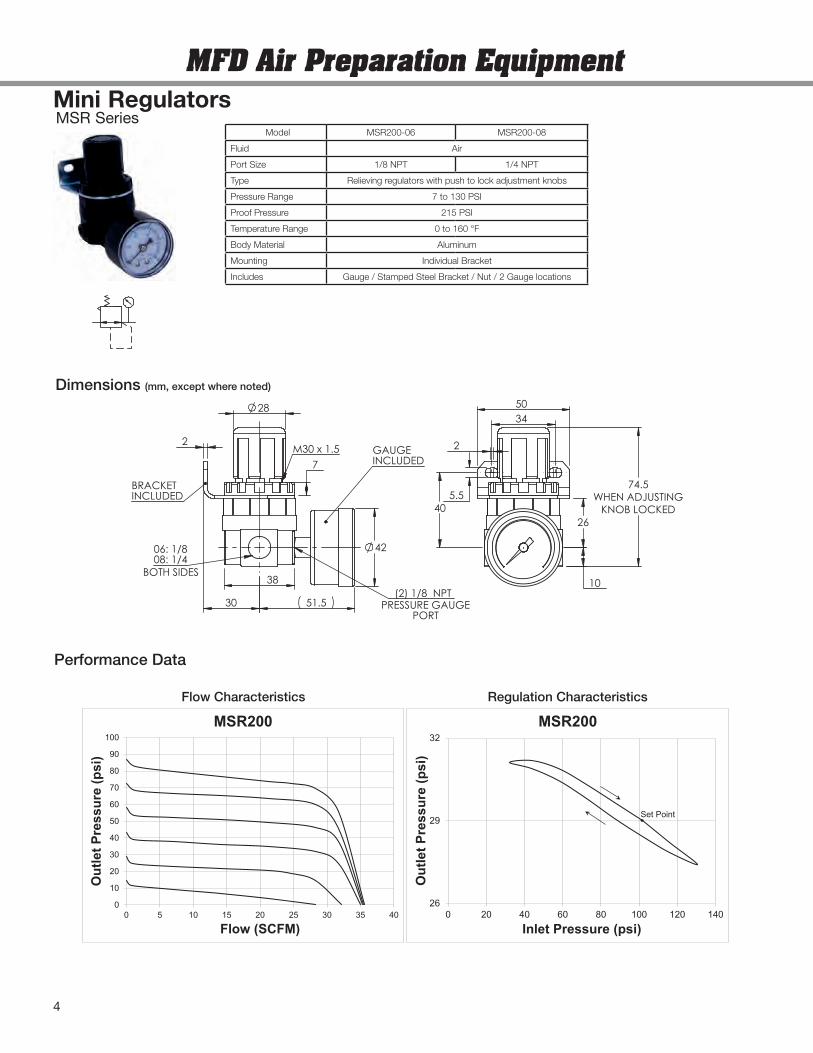
Mini RegulatorsMSR Series
0
10
20
30
40
50
60
70
80
90
100
0 5 10 15 20 25 30 35 40
OutletPressure(psi)
Flow (SCFM)
MSR200
26
29
32
0 20 40 60 80 100 120 140
OutletPressure(psi)
Inlet Pressure (psi)
MSR200
Set Point
Performance Data
Dimensions (mm, except where noted)
Flow Characteristics Regulation Characteristics
34
08: 1/4
(2) 1/8 NPT
06: 1/8
M30 x 1.5
38
2
7
30
42
51.5
28
BRACKETINCLUDED
GAUGEINCLUDED
BOTH SIDES
PRESSURE GAUGEPORT
40
50
5.5 WHEN ADJUSTINGKNOB LOCKED
2
74.5
10
26
Model MSR200-06 MSR200-08
Fluid Air
Port Size 1/8 NPT 1/4 NPT
Type Relieving regulators with push to lock adjustment knobs
Pressure Range 7 to 130 PSI
Proof Pressure 215 PSI
Temperature Range 0 to 160 °F
Body Material Aluminum
Mounting Individual Bracket
Includes Gauge / Stamped Steel Bracket / Nut / 2 Gauge locations
MFD Air Preparation Equipment
4
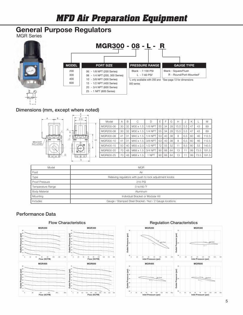
General Purpose RegulatorsMGR Series
Performance Data
0
10
20
30
40
50
60
70
80
90
0 20 40 60 80 100 120 140
OutletPressure(psi)
Flow (SCFM)
MGR200
0
10
20
30
40
50
60
70
80
90
0 20 40 60 80 100 120 140 160
OutletPressure(psi)
Flow (SCFM)
MGR300
0
10
20
30
40
50
60
70
80
90
0 50 100 150 200 250
OutletPressure(psi)
Flow (SCFM)
MGR400
0
10
20
30
40
50
60
70
80
90
0 50 100 150 200 250 300 350 400 450
OutletPressure(psi)
Flow (SCFM)
MGR600
26
29
32
0 20 40 60 80 100 120 140
OutletPressure(psi)
Inlet Pressure (psi)
MGR200
Set Point
26
29
32
0 20 40 60 80 100 120 140
OutletPressure(psi)
Inlet Pressure (psi)
MGR300
Set Point
26
29
32
0 20 40 60 80 100 120 140 160
OutletPressure(psi)
Inlet Pressure (psi)
MGR600
Set Point
26
27
28
29
30
31
32
0 20 40 60 80 100 120 140 160
OutletPressure(psi)
Inlet Pressure (psi)
MGR400
Set Point
Flow Characteristics Regulation Characteristics
Model MGR
Fluid Air
Type Relieving regulators with push to lock adjustment knobs
Proof Pressure 215 PSI
Temperature Range 0 to160 ˚F
Body Material Aluminum
Mounting Individual Bracket or Modular Kit
Includes Gauge / Stamped Steel Bracket / Nut / 2 Gauge locations
Model A B C D E F G H J K L M
MGR200-06 30 32 M30 x 1.5 1/8 NPT 55 34 28 15.5 5.5 47 43 89
MGR200-08 30 32 M30 x 1.5 1/4 NPT 55 34 28 15.5 5.5 47 43 89
MGR300-08 41 31 M40 x 1.5 1/4 NPT 53 40 38 8 6.5 60 46 112.5
MGR300-10 41 31 M40 x 1.5 3/8 NPT 53 40 38 8 6.5 60 46 112.5
MGR400-15 50 40 M55 x 2.0 1/2 NPT 72 55 52 11 8.5 80 53 140.5
MGR600-20 70 48 M68 x 1.5 3/4 NPT 90 66 64 13 11 99 73.5 191.5
MGR600-25 70 48 M68 x 1.5 1 NPT 90 66 64 13 11 99 73.5 191.5
Dimensions (mm, except where noted)F
H
E
L
G
MJ
K
C
BA
D
BRACKETINCLUDED
MFD Air Preparation Equipment
MGR300 - 08 - L - R
200
300
400
600
MODEL
06 - 1/8 NPT (200 Series)
08 - 1/4 NPT (200, 300 Series)
10 - 3/8 NPT (300 Series)
15 - 1/2 NPT (400 Series)
20 - 3/4 NPT (600 Series)
25 - 1 NPT (600 Series)
PORT SIZE GAUGE TYPE
Blank - 7-130 PSI
L - 7-60 PSI1
PRESSURE RANGE
1L only available with 200 and
300 series
Blank - Square/FlushR - Round/Port-Mounted2
5
2See page 13 for dimensions
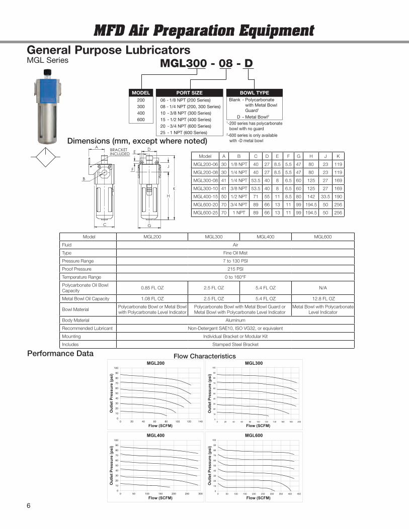
General Purpose LubricatorsMGL Series
Performance Data
0
10
20
30
40
50
60
70
80
90
100
0 20 40 60 80 100 120 140 160 180 200
OutletPressure(psi)
Flow (SCFM)
MGL300
0102030405060708090100
0 50 100 150 200 250 300
OutletPressure(psi)
Flow (SCFM)
MGL400
0
10
20
30
40
50
60
70
80
90
100
0 50 100 150 200 250 300 350 400 450
OutletPressure(psi)
Flow (SCFM)
MGL600
0102030405060708090100
0 20 40 60 80 100 120 140
OutletPressure(psi)
Flow (SCFM)
MGL200Flow Characteristics
MFD Air Preparation Equipment
Model MGL200 MGL300 MGL400 MGL600
Fluid Air
Type Fine Oil Mist
Pressure Range 7 to 130 PSI
Proof Pressure 215 PSI
Temperature Range 0 to 160°F
Polycarbonate Oil BowlCapacity
0.85 FL OZ 2.5 FL OZ 5.4 FL OZ N/A
Metal Bowl Oil Capacity 1.08 FL OZ 2.5 FL OZ 5.4 FL OZ 12.8 FL OZ
Bowl MaterialPolycarbonate Bowl or Metal Bowlwith Polycarbonate Level Indicator
Polycarbonate Bowl with Metal Bowl Guard orMetal Bowl with Polycarbonate Level Indicator
Metal Bowl with PolycarbonateLevel Indicator
Body Material Aluminum
Recommended Lubricant Non-Detergent SAE10, ISO VG32, or equivalent
Mounting Individual Bracket or Modular Kit
Includes Stamped Steel Bracket
Model A B C D E F G H J K
MGL200-06 30 1/8 NPT 40 27 8.5 5.5 47 80 23 119
MGL200-08 30 1/4 NPT 40 27 8.5 5.5 47 80 23 119
MGL300-08 41 1/4 NPT 53.5 40 8 6.5 60 125 27 169
MGL300-10 41 3/8 NPT 53.5 40 8 6.5 60 125 27 169
MGL400-15 50 1/2 NPT 71 55 11 8.5 80 142 33.5 190
MGL600-20 70 3/4 NPT 89 66 13 11 99 194.5 50 256
MGL600-25 70 1 NPT 89 66 13 11 99 194.5 50 256
Dimensions (mm, except where noted)D
E
H
J
B
A
C
BRACKETINCLUDED
G
F
K
MGL300 - 08 - D
200300400600
MODEL06 - 1/8 NPT (200 Series)08 - 1/4 NPT (200, 300 Series)10 - 3/8 NPT (300 Series)15 - 1/2 NPT (400 Series)20 - 3/4 NPT (600 Series)25 - 1 NPT (600 Series)
PORT SIZE BOWL TYPEBlank - Polycarbonate
with Metal BowlGuard1
D - Metal Bowl21-200 series has polycarbonatebowl with no guard
2-600 series is only availablewith -D metal bowl
6
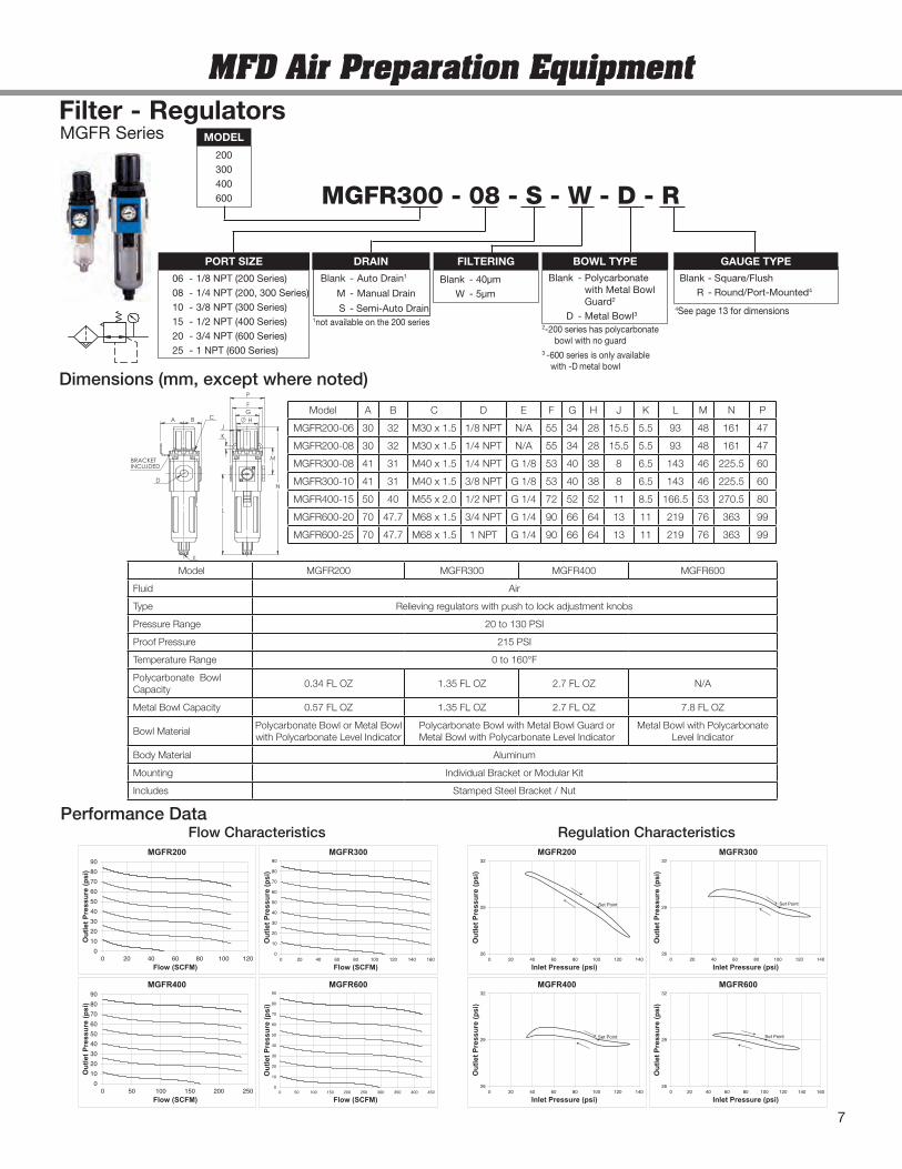
MGFR SeriesFilter - Regulators
Performance Data
0102030405060708090
0 20 40 60 80 100 120
OutletPressure(psi)
Flow (SCFM)
MGFR200
0
10
20
30
40
50
60
70
80
90
0 20 40 60 80 100 120 140 160
OutletPressure(psi)
Flow (SCFM)
MGFR300
0102030405060708090
0 50 100 150 200 250
OutletPressure(psi)
Flow (SCFM)
MGFR400
0
10
20
30
40
50
60
70
80
90
0 50 100 150 200 250 300 350 400 450
OutletPressure(psi)
Flow (SCFM)
MGFR600
26
29
32
0 20 40 60 80 100 120 140
OutletPressure(psi)
Inlet Pressure (psi)
MGFR200
Set Point
26
29
32
0 20 40 60 80 100 120 140
OutletPressure(psi)
Inlet Pressure (psi)
MGFR300
Set Point
26
29
32
0 20 40 60 80 100 120 140
OutletPressure(psi)
Inlet Pressure (psi)
MGFR400
Set Point
26
29
32
0 20 40 60 80 100 120 140 160
OutletPressure(psi)
Inlet Pressure (psi)
MGFR600
Set Point
Flow Characteristics Regulation Characteristics
Model MGFR200 MGFR300 MGFR400 MGFR600
Fluid Air
Type Relieving regulators with push to lock adjustment knobs
Pressure Range 20 to 130 PSI
Proof Pressure 215 PSI
Temperature Range 0 to 160°F
Polycarbonate BowlCapacity
0.34 FL OZ 1.35 FL OZ 2.7 FL OZ N/A
Metal Bowl Capacity 0.57 FL OZ 1.35 FL OZ 2.7 FL OZ 7.8 FL OZ
Bowl MaterialPolycarbonate Bowl or Metal Bowlwith Polycarbonate Level Indicator
Polycarbonate Bowl with Metal Bowl Guard orMetal Bowl with Polycarbonate Level Indicator
Metal Bowl with PolycarbonateLevel Indicator
Body Material Aluminum
Mounting Individual Bracket or Modular Kit
Includes Stamped Steel Bracket / Nut
Model A B C D E F G H J K L M N P
MGFR200-06 30 32 M30 x 1.5 1/8 NPT N/A 55 34 28 15.5 5.5 93 48 161 47
MGFR200-08 30 32 M30 x 1.5 1/4 NPT N/A 55 34 28 15.5 5.5 93 48 161 47
MGFR300-08 41 31 M40 x 1.5 1/4 NPT G 1/8 53 40 38 8 6.5 143 46 225.5 60
MGFR300-10 41 31 M40 x 1.5 3/8 NPT G 1/8 53 40 38 8 6.5 143 46 225.5 60
MGFR400-15 50 40 M55 x 2.0 1/2 NPT G 1/4 72 52 52 11 8.5 166.5 53 270.5 80
MGFR600-20 70 47.7 M68 x 1.5 3/4 NPT G 1/4 90 66 64 13 11 219 76 363 99
MGFR600-25 70 47.7 M68 x 1.5 1 NPT G 1/4 90 66 64 13 11 219 76 363 99
Dimensions (mm, except where noted)
L
N
F
M
HG
K
J
P
C
E
A B
D
BRACKETINCLUDED
MFD Air Preparation Equipment
200300400600
MODEL
06 - 1/8 NPT (200 Series)08 - 1/4 NPT (200, 300 Series)10 - 3/8 NPT (300 Series)15 - 1/2 NPT (400 Series)20 - 3/4 NPT (600 Series)25 - 1 NPT (600 Series)
PORT SIZE GAUGE TYPE
Blank - 40µmW - 5µm
FILTERING
MGFR300 - 08 - S - W - D - R
Blank - Polycarbonatewith Metal BowlGuard2
D - Metal Bowl3
BOWL TYPE
2-200 series has polycarbonatebowl with no guard
3 -600 series is only availablewith -Dmetal bowl
1not available on the 200 series
DRAIN
Blank - Auto Drain1
M - Manual Drain
S - Semi-Auto Drain
7
Blank - Square/FlushR - Round/Port-Mounted4
4See page 13 for dimensions
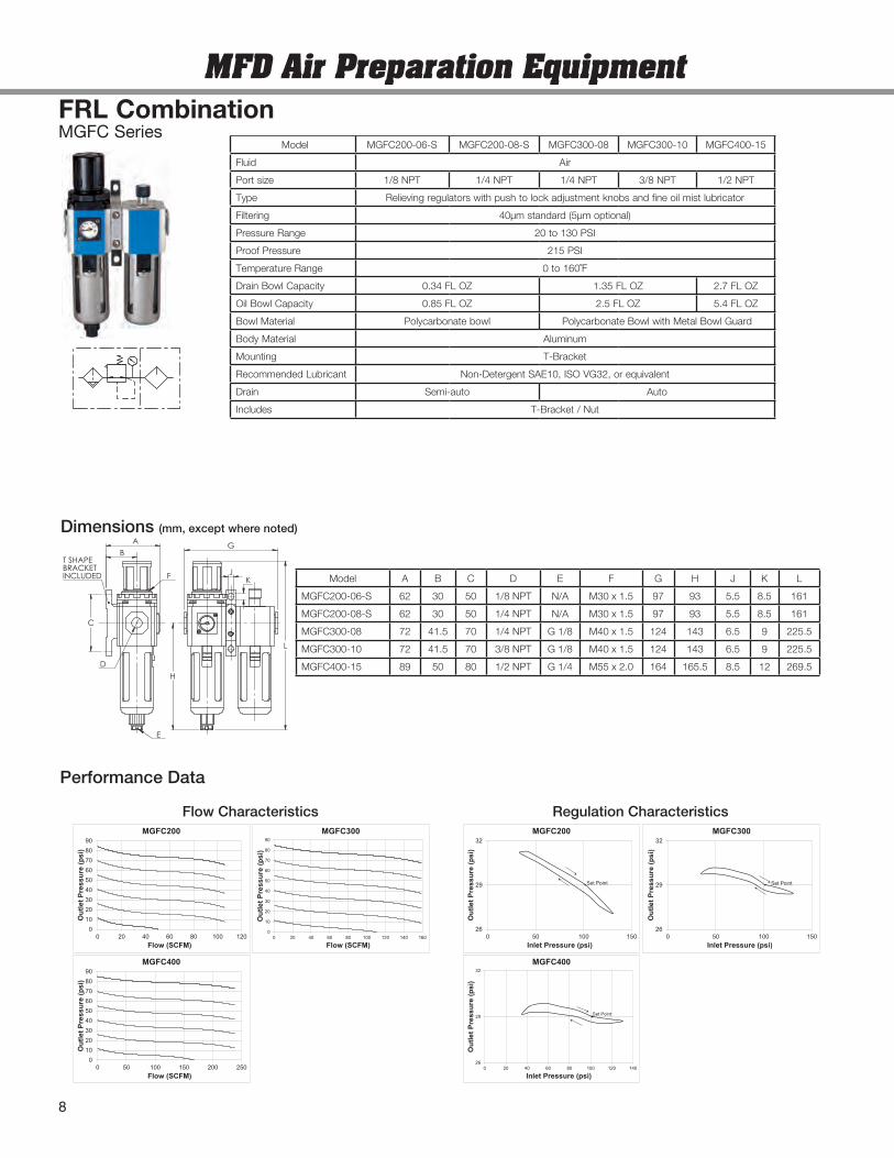
Model MGFC200-06-S MGFC200-08-S MGFC300-08 MGFC300-10 MGFC400-15
Fluid Air
Port size 1/8 NPT 1/4 NPT 1/4 NPT 3/8 NPT 1/2 NPT
Type Relieving regulators with push to lock adjustment knobs and fine oil mist lubricator
Filtering 40µm standard (5µm optional)
Pressure Range 20 to 130 PSI
Proof Pressure 215 PSI
Temperature Range 0 to 160˚F
Drain Bowl Capacity 0.34 FL OZ 1.35 FL OZ 2.7 FL OZ
Oil Bowl Capacity 0.85 FL OZ 2.5 FL OZ 5.4 FL OZ
Bowl Material Polycarbonate bowl Polycarbonate Bowl with Metal Bowl Guard
Body Material Aluminum
Mounting T-Bracket
Recommended Lubricant Non-Detergent SAE10, ISO VG32, or equivalent
Drain Semi-auto Auto
Includes T-Bracket / Nut
MGFC SeriesFRL Combination
Model A B C D E F G H J K L
MGFC200-06-S 62 30 50 1/8 NPT N/A M30 x 1.5 97 93 5.5 8.5 161
MGFC200-08-S 62 30 50 1/4 NPT N/A M30 x 1.5 97 93 5.5 8.5 161
MGFC300-08 72 41.5 70 1/4 NPT G 1/8 M40 x 1.5 124 143 6.5 9 225.5
MGFC300-10 72 41.5 70 3/8 NPT G 1/8 M40 x 1.5 124 143 6.5 9 225.5
MGFC400-15 89 50 80 1/2 NPT G 1/4 M55 x 2.0 164 165.5 8.5 12 269.5
Performance Data
Dimensions (mm, except where noted)
0102030405060708090
0 20 40 60 80 100 120
OutletPressure(psi)
Flow (SCFM)
MGFC200
0
10
20
30
40
50
60
70
80
90
0 20 40 60 80 100 120 140 160
OutletPressure(psi)
Flow (SCFM)
MGFC300
0102030405060708090
0 50 100 150 200 250
OutletPressure(psi)
Flow (SCFM)
MGFC400
26
29
32
0 50 100 150
OutletPressure(psi)
Inlet Pressure (psi)
MGFC200
Set Point
26
29
32
0 50 100 150
OutletPressure(psi)
Inlet Pressure (psi)
MGFC300
Set Point
26
29
32
0 20 40 60 80 100 120 140
OutletPressure(psi)
Inlet Pressure (psi)
MGFC400
Set Point
Flow Characteristics Regulation Characteristics
C
L
G
H
JK
E
F
AB
D
T SHAPEBRACKETINCLUDED
MFD Air Preparation Equipment
8
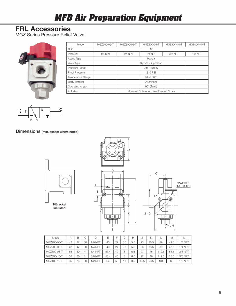
FRL AccessoriesMGZ Series Pressure Relief Valve
F
K
J
M
A
B
H
G
L
NE
C
2 - D
BRACKETINCLUDED
Model A B C D E F G H J K L M N
MGZ200-06-T 42 47 30 1/8 NPT 40 27 8.5 5.5 23 36.5 89 42.5 1/4 NPT
MGZ200-08-T 42 47 30 1/4 NPT 40 27 8.5 5.5 23 36.5 89 42.5 1/4 NPT
MGZ300-08-T 55 60 41 1/4 NPT 53.4 40 8 6.5 27 46 112.5 56.5 3/8 NPT
MGZ300-10-T 55 60 41 3/8 NPT 53.4 40 8 6.5 27 46 112.5 56.5 3/8 NPT
MGZ400-15-T 65 75 50 1/2 NPT 64 55 11 8.5 33.5 58.5 134 66 1/2 NPT
Model MGZ200-06-T MGZ200-08-T MGZ300-08-T MGZ300-10-T MGZ400-15-T
Fluid Air
Port Size 1/8 NPT 1/4 NPT 1/4 NPT 3/8 NPT 1/2 NPT
Acting Type Manual
Valve Type 3 ports - 2 position
Pressure Range 0 to 130 PSI
Proof Pressure 215 PSI
Temperature Range 0 to 160°F
Body Material Aluminum
Operating Angle 90° (Twist)
Includes T-Bracket / Stamped Steel Bracket / Lock
A
P R
Dimensions (mm, except where noted)
MFD Air Preparation Equipment
T-BracketIncluded
9
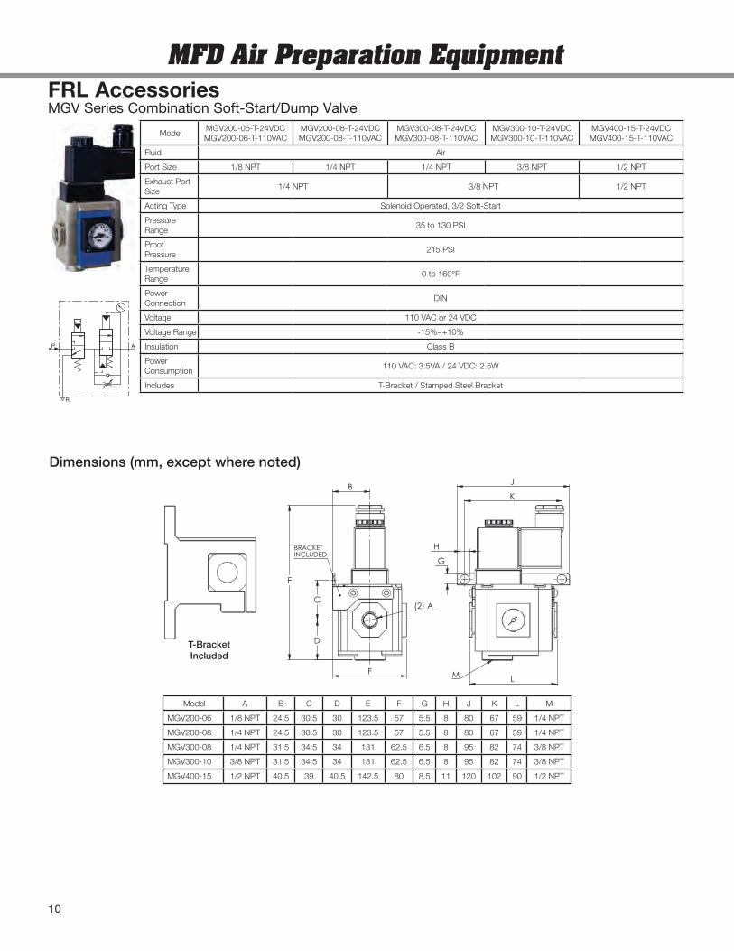
FRL AccessoriesMGV Series Combination Soft-Start/Dump Valve
C
G
H
B
E
F
D
(2) A
BRACKETINCLUDED
M
J
L
K
Model A B C D E F G H J K L M
MGV200-06 1/8 NPT 24.5 30.5 30 123.5 57 5.5 8 80 67 59 1/4 NPT
MGV200-08 1/4 NPT 24.5 30.5 30 123.5 57 5.5 8 80 67 59 1/4 NPT
MGV300-08 1/4 NPT 31.5 34.5 34 131 62.5 6.5 8 95 82 74 3/8 NPT
MGV300-10 3/8 NPT 31.5 34.5 34 131 62.5 6.5 8 95 82 74 3/8 NPT
MGV400-15 1/2 NPT 40.5 39 40.5 142.5 80 8.5 11 120 102 90 1/2 NPT
ModelMGV200-06-T-24VDCMGV200-06-T-110VAC
MGV200-08-T-24VDCMGV200-08-T-110VAC
MGV300-08-T-24VDCMGV300-08-T-110VAC
MGV300-10-T-24VDCMGV300-10-T-110VAC
MGV400-15-T-24VDCMGV400-15-T-110VAC
Fluid Air
Port Size 1/8 NPT 1/4 NPT 1/4 NPT 3/8 NPT 1/2 NPT
Exhaust PortSize
1/4 NPT 3/8 NPT 1/2 NPT
Acting Type Solenoid Operated, 3/2 Soft-Start
PressureRange
35 to 130 PSI
ProofPressure
215 PSI
TemperatureRange
0 to 160°F
PowerConnection
DIN
Voltage 110 VAC or 24 VDC
Voltage Range -15%~+10%
Insulation Class B
PowerConsumption
110 VAC: 3.5VA / 24 VDC: 2.5W
Includes T-Bracket / Stamped Steel Bracket
Dimensions (mm, except where noted)
R
P A
T-BracketIncluded
MFD Air Preparation Equipment
10
C
A
D
B
E
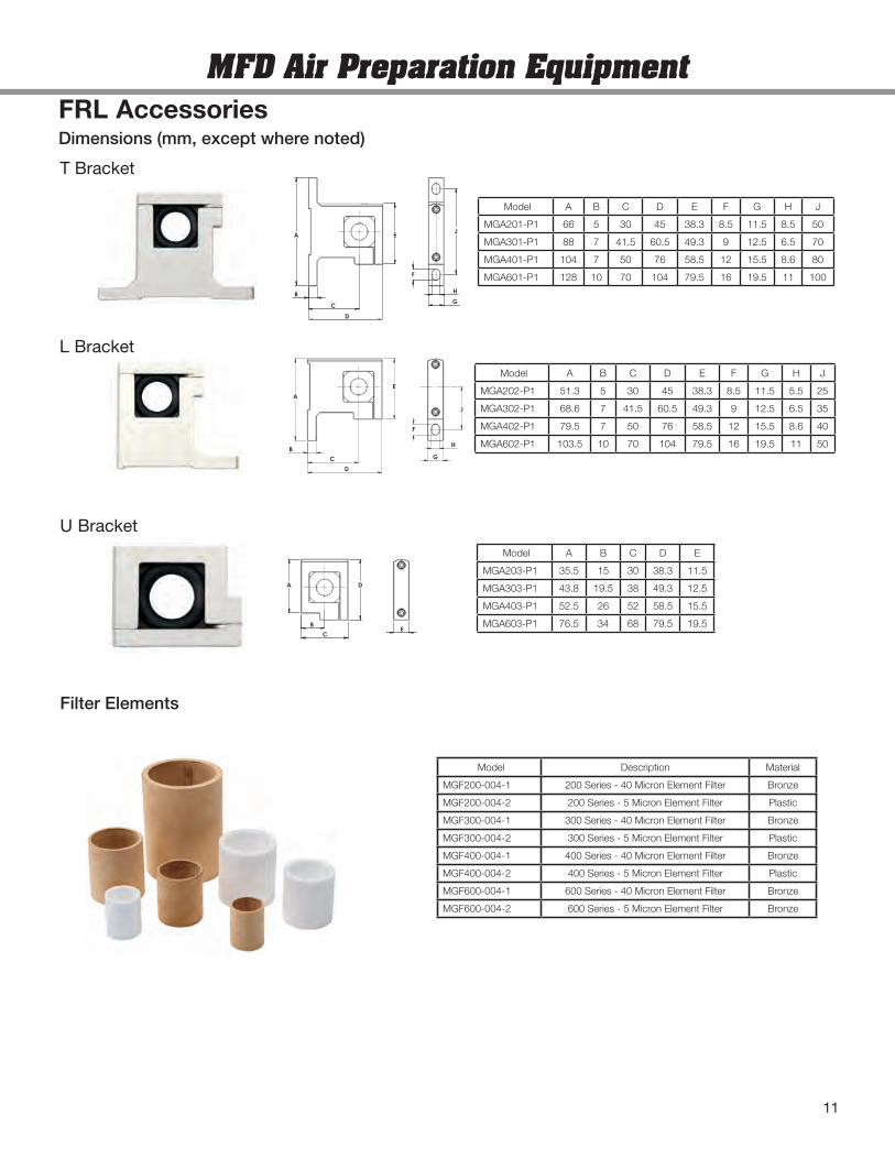
Model A B C D E F G H J
MGA202-P1 51.3 5 30 45 38.3 8.5 11.5 5.5 25
MGA302-P1 68.6 7 41.5 60.5 49.3 9 12.5 6.5 35
MGA402-P1 79.5 7 50 76 58.5 12 15.5 8.6 40
MGA602-P1 103.5 10 70 104 79.5 16 19.5 11 50
JA
D
B
C
E
H
F
G
Model A B C D E F G H J
MGA201-P1 66 5 30 45 38.3 8.5 11.5 8.5 50
MGA301-P1 88 7 41.5 60.5 49.3 9 12.5 6.5 70
MGA401-P1 104 7 50 76 58.5 12 15.5 8.6 80
MGA601-P1 128 10 70 104 79.5 16 19.5 11 100
C
A
B
D
E
Model A B C D E
MGA203-P1 35.5 15 30 38.3 11.5
MGA303-P1 43.8 19.5 38 49.3 12.5
MGA403-P1 52.5 26 52 58.5 15.5
MGA603-P1 76.5 34 68 79.5 19.5
Model Description Material
MGF200-004-1 200 Series - 40 Micron Element Filter Bronze
MGF200-004-2 200 Series - 5 Micron Element Filter Plastic
MGF300-004-1 300 Series - 40 Micron Element Filter Bronze
MGF300-004-2 300 Series - 5 Micron Element Filter Plastic
MGF400-004-1 400 Series - 40 Micron Element Filter Bronze
MGF400-004-2 400 Series - 5 Micron Element Filter Plastic
MGF600-004-1 600 Series - 40 Micron Element Filter Bronze
MGF600-004-2 600 Series - 5 Micron Element Filter Bronze
FRL Accessories
L Bracket
T Bracket
U Bracket
Dimensions (mm, except where noted)
Filter Elements
J
F
H
G
MFD Air Preparation Equipment
11
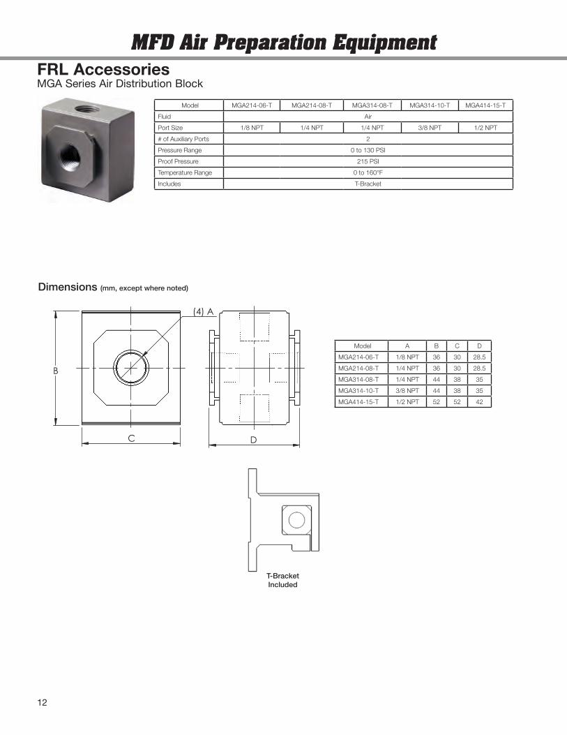
MGA Series Air Distribution BlockFRL Accessories
B
C
(4) A
D
Model A B C D
MGA214-06-T 1/8 NPT 36 30 28.5
MGA214-08-T 1/4 NPT 36 30 28.5
MGA314-08-T 1/4 NPT 44 38 35
MGA314-10-T 3/8 NPT 44 38 35
MGA414-15-T 1/2 NPT 52 52 42
Model MGA214-06-T MGA214-08-T MGA314-08-T MGA314-10-T MGA414-15-T
Fluid Air
Port Size 1/8 NPT 1/4 NPT 1/4 NPT 3/8 NPT 1/2 NPT
# of Auxiliary Ports 2
Pressure Range 0 to 130 PSI
Proof Pressure 215 PSI
Temperature Range 0 to 160°F
Includes T-Bracket
Dimensions (mm, except where noted)
MFD Air Preparation Equipment
T-BracketIncluded
12
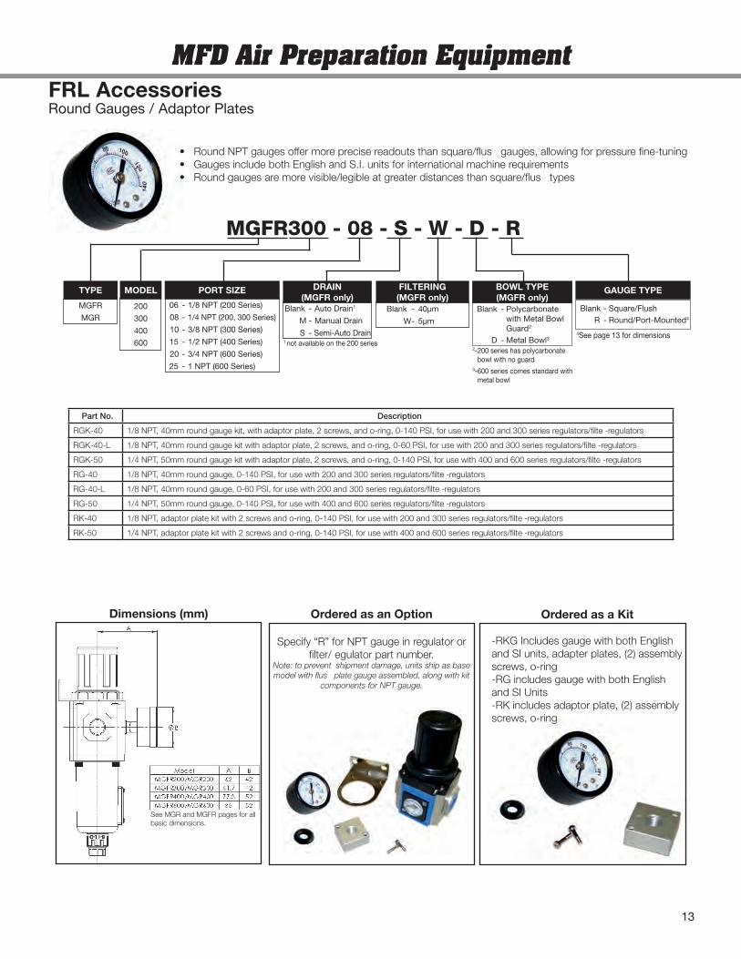
Part No. Description
RGK-40 1/8 NPT, 40mm round gauge kit, with adaptor plate, 2 screws, and o-ring, 0-140 PSI, for use with 200 and 300 series regulators/filte -regulators
RGK-40-L 1/8 NPT, 40mm round gauge kit with adaptor plate, 2 screws, and o-ring, 0-60 PSI, for use with 200 and 300 series regulators/filte -regulators
RGK-50 1/4 NPT, 50mm round gauge kit with adaptor plate, 2 screws, and o-ring, 0-140 PSI, for use with 400 and 600 series regulators/filte -regulators
RG-40 1/8 NPT, 40mm round gauge, 0-140 PSI, for use with 200 and 300 series regulators/filte -regulators
RG-40-L 1/8 NPT, 40mm round gauge, 0-60 PSI, for use with 200 and 300 series regulators/filte -regulators
RG-50 1/4 NPT, 50mm round gauge, 0-140 PSI, for use with 400 and 600 series regulators/filte -regulators
RK-40 1/8 NPT, adaptor plate kit with 2 screws and o-ring, 0-140 PSI, for use with 200 and 300 series regulators/filte -regulators
RK-50 1/4 NPT, adaptor plate kit with 2 screws and o-ring, 0-140 PSI, for use with 400 and 600 series regulators/filte -regulators
MFD Air Preparation Equipment
Dimensions (mm)
See MGR and MGFR pages for allbasic dimensions.
-RKG Includes gauge with both Englishand SI units, adapter plates, (2) assemblyscrews, o-ring-RG includes gauge with both Englishand SI Units-RK includes adaptor plate, (2) assemblyscrews, o-ring
Specify “R” for NPT gauge in regulator orfilter/ egulator part number.
Note: to prevent shipment damage, units ship as basemodel with flus plate gauge assembled, along with kit
components for NPT gauge.
Ordered as an Option Ordered as a Kit
FRL AccessoriesRound Gauges / Adaptor Plates
MGFR300 - 08 - S - W - D - R
200
300
400
600
MODEL
06 - 1/8 NPT (200 Series)
08 - 1/4 NPT (200, 300 Series)
10 - 3/8 NPT (300 Series)
15 - 1/2 NPT (400 Series)
20 - 3/4 NPT (600 Series)
25 - 1 NPT (600 Series)
PORT SIZE
Blank - 40µm
W- 5µm
FILTERING(MGFR only)
Blank - Auto Drain1
M - Manual Drain
S - Semi-Auto Drain
DRAIN(MGFR only)
1not available on the 200 series
GAUGE TYPE
Blank - Polycarbonatewith Metal BowlGuard2
D - Metal Bowl3
BOWL TYPE(MGFR only)
2-200 series has polycarbonatebowl with no guard
3-600 series comes standard withmetal bowl
MGFR
MGR
TYPE
13
• Round NPT gauges offer more precise readouts than square/flus gauges, allowing for pressure fine-tuning• Gauges include both English and S.I. units for international machine requirements• Round gauges are more visible/legible at greater distances than square/flus types
Blank - Square/FlushR - Round/Port-Mounted4
4See page 13 for dimensions
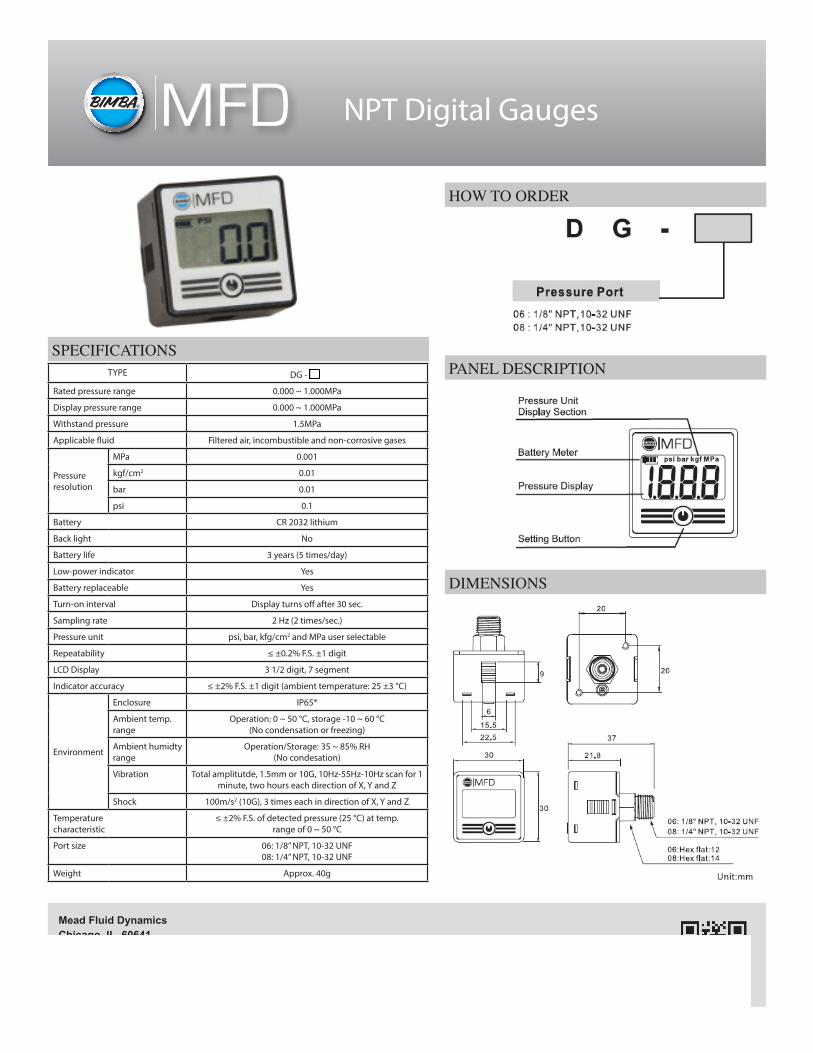
NPT Digital Gauges
Leaders in Actuation.To learn more about this
product, scan this QR code with your mobile device.
Mead Fluid DynamicsChicago, IL 60641 Telephone: 773.685.6800Toll Free: 877.MEAD.USA Email: [email protected] www.mead-usa.com MFD-RG-214
HOW TO ORDER
TYPE DG -
Rated pressure range 0.000 ~ 1.000MPa
Display pressure range 0.000 ~ 1.000MPa
Withstand pressure 1.5MPa
Applicable fluid Filtered air, incombustible and non-corrosive gases
Pressure resolution
MPa 0.001
kgf/cm2 0.01
bar 0.01
psi 0.1
Battery CR 2032 lithium
Back light No
Battery life 3 years (5 times/day)
Low-power indicator Yes
Battery replaceable Yes
Turn-on interval Display turns off after 30 sec.
Sampling rate 2 Hz (2 times/sec.)
Pressure unit psi, bar, kfg/cm2 and MPa user selectable
Repeatability ≤ ±0.2% F.S. ±1 digit
LCD Display 3 1/2 digit, 7 segment
Indicator accuracy ≤ ±2% F.S. ±1 digit (ambient temperature: 25 ±3 °C)
Environment
Enclosure IP65*
Ambient temp. range
Operation: 0 ~ 50 °C, storage -10 ~ 60 °C (No condensation or freezing)
Ambient humidty range
Operation/Storage: 35 ~ 85% RH (No condesation)
Vibration Total amplitutde, 1.5mm or 10G, 10Hz-55Hz-10Hz scan for 1 minute, two hours each direction of X, Y and Z
Shock 100m/s2 (10G), 3 times each in direction of X, Y and Z
Temperature characteristic
≤ ±2% F.S. of detected pressure (25 °C) at temp.range of 0 ~ 50 °C
Port size 06: 1/8” NPT, 10-32 UNF08: 1/4” NPT, 10-32 UNF
Weight Approx. 40g
PANEL DESCRIPTION
DIMENSIONS
SPECIFICATIONS
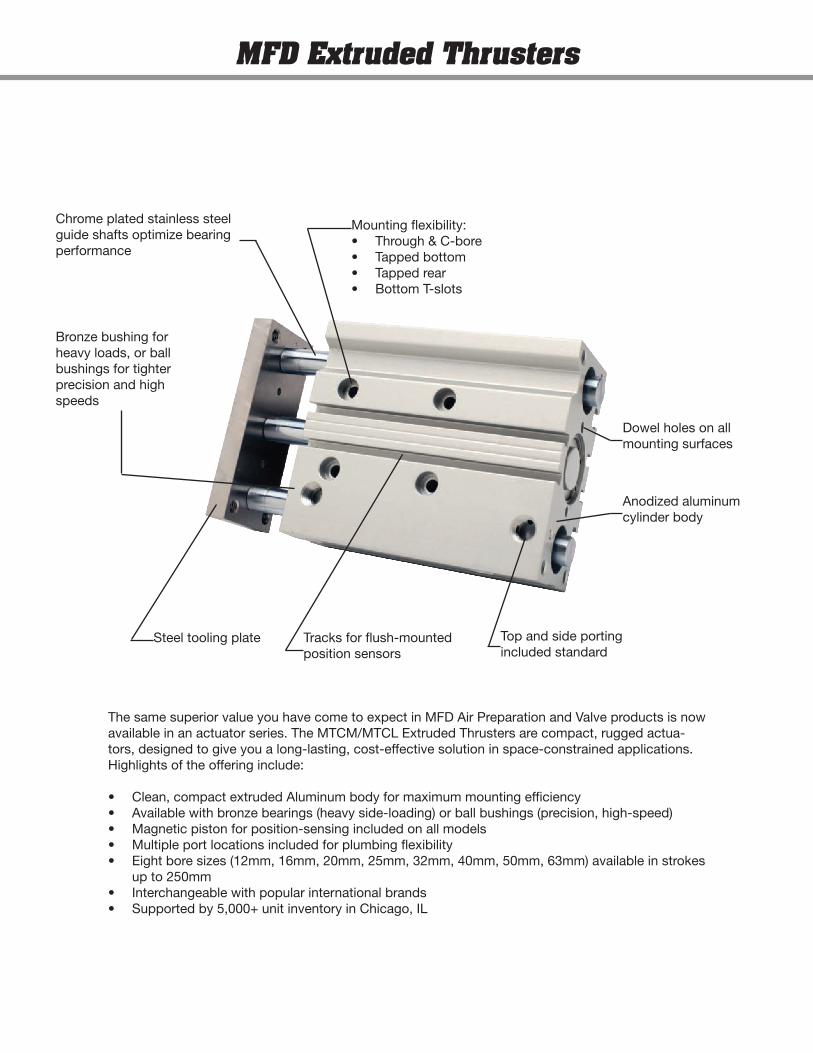
The same superior value you have come to expect in MFD Air Preparation and Valve products is now available in an actuator series. The MTCM/MTCL Extruded Thrusters are compact, rugged actua-tors, designed to give you a long-lasting, cost-effective solution in space-constrained applications. Highlights of the offering include:
• Clean, compact extruded Aluminum body for maximum mounting efficiency• Available with bronze bearings (heavy side-loading) or ball bushings (precision, high-speed)• Magnetic piston for position-sensing included on all models• Multiple port locations included for plumbing flexibility• Eight bore sizes (12mm, 16mm, 20mm, 25mm, 32mm, 40mm, 50mm, 63mm) available in strokes
up to 250mm• Interchangeable with popular international brands• Supported by 5,000+ unit inventory in Chicago, IL
Bronze bushing for heavy loads, or ball bushings for tighter precision and high speeds
Chrome plated stainless steel guide shafts optimize bearing performance
Mounting flexibility:• Through & C-bore• Tapped bottom• Tapped rear• Bottom T-slots
Dowel holes on all mounting surfaces
Anodized aluminum cylinder body
Top and side porting included standard
Tracks for flush-mounted position sensors
Steel tooling plate
MFD Extruded Thrusters
12 16 20 25 32 40 50 63
10 X X
20 X X X X
25 X X X X X X X X
30 X X X X X X X X
40 X X X X X X X X
50 X X X X X X X X
60 X X X X X X X X
70 X X X X X X X X
75 X X X X X X X X
80 X X X X X X X X
90 X X X X X X X X
100 X X X X X X X X
125 X X X X X X X X
150 X X X X X X X X
175 X X X X X X X
200 X X X X X X X
225 X X X X X X
250 X X X X X X
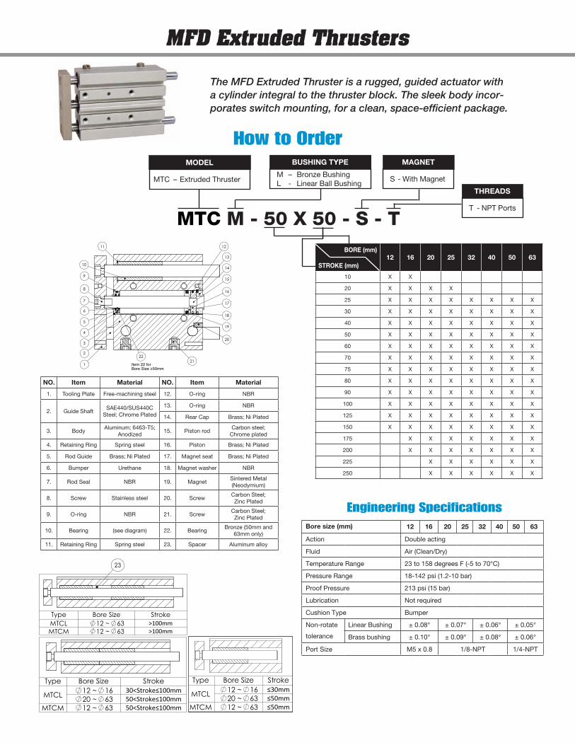
The MFD Extruded Thruster is a rugged, guided actuator with a cylinder integral to the thruster block. The sleek body incor-porates switch mounting, for a clean, space-efficient package.
MTC M - 50 X 50 - S - T
MFD Extruded Thrusters
How to Order
MTC – Extruded Thruster
MODEL
M – Bronze BushingL - Linear Ball Bushing
BUSHING TYPE
S - With Magnet
MAGNET
T - NPT Ports
THREADS
STROKE (mm)
BORE (mm)
Item 22 forBore Size ≥50mm
13
11
14
15
4
618
21
8
3
5
2
1
19
20
12
16
9
10
177
22
Bore size (mm) 12 16 20 25 32 40 50 63
Action Double acting
Fluid Air (Clean/Dry)
Temperature Range 23 to 158 degrees F (-5 to 70°C)
Pressure Range 18-142 psi (1.2-10 bar)
Proof Pressure 213 psi (15 bar)
Lubrication Not required
Cushion Type Bumper
Non-rotate
tolerance
Linear Bushing ± 0.08° ± 0.07° ± 0.06° ± 0.05°
Brass bushing ± 0.10° ± 0.09° ± 0.08° ± 0.06°
Port Size M5 x 0.8 1/8-NPT 1/4-NPT
Engineering Specifications
Type Bore Size Stroke
MTCL12 ~ 16 30<Stroke≤100mm20 ~ 63 50<Stroke≤100mm
MTCM 12 ~ 63 50<Stroke≤100mm
23
Type Bore Size StrokeMTCL 12 ~ 63 >100mmMTCM 12 ~ 63 >100mm
Type Bore Size Stroke
MTCL12 ~ 16 ≤30mm20 ~ 63 ≤50mm
MTCM 12 ~ 63 ≤50mm
NO. Item Material NO. Item Material
1. Tooling Plate Free-machining steel 12. O-ring NBR
2. Guide ShaftSAE440/SUS440C
Steel; Chrome Plated
13. O-ring NBR
14. Rear Cap Brass; Ni Plated
3. BodyAluminum; 6463-T5;
Anodized15. Piston rod
Carbon steel; Chrome plated
4. Retaining Ring Spring steel 16. Piston Brass; Ni Plated
5. Rod Guide Brass; Ni Plated 17. Magnet seat Brass; Ni Plated
6. Bumper Urethane 18. Magnet washer NBR
7. Rod Seal NBR 19. MagnetSintered Metal (Neodymium)
8. Screw Stainless steel 20. ScrewCarbon Steel; Zinc Plated
9. O-ring NBR 21. ScrewCarbon Steel; Zinc Plated
10. Bearing (see diagram) 22. BearingBronze (50mm and
63mm only)
11. Retaining Ring Spring steel 23. Spacer Aluminum alloy
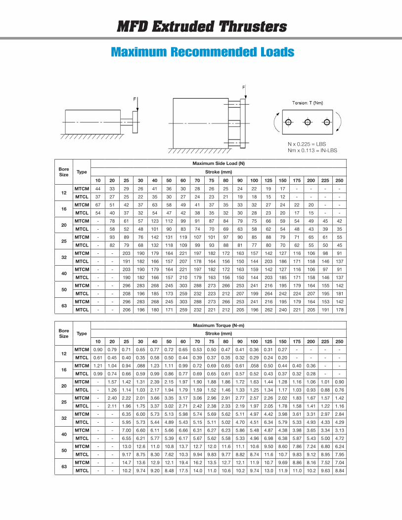
Bore Size
Type
Maximum Side Load (N)
Stroke (mm)
10 20 25 30 40 50 60 70 75 80 90 100 125 150 175 200 225 250
12MTCM 44 33 29 26 41 36 30 28 26 25 24 22 19 17 - - - -
MTCL 37 27 25 22 35 30 27 24 23 21 19 18 15 12 - - - -
16MTCM 67 51 42 37 63 58 49 41 37 35 33 32 27 24 22 20 - -
MTCL 54 40 37 32 54 47 42 38 35 32 30 28 23 20 17 15 - -
20MTCM - 78 61 57 123 112 99 91 87 84 79 75 66 59 54 49 45 42
MTCL - 58 52 48 101 90 83 74 70 69 63 58 62 54 48 43 39 35
25MTCM - 93 89 76 142 131 119 107 101 97 90 85 88 79 71 65 61 55
MTCL - 82 79 68 132 118 109 99 93 88 81 77 80 70 62 55 50 45
32MTCM - - 203 190 179 164 221 197 182 172 163 157 142 127 116 106 98 91
MTCL - - 191 182 166 157 207 178 164 156 150 144 203 186 171 158 146 137
40MTCM - - 203 190 179 164 221 197 182 172 163 159 142 127 116 106 97 91
MTCL - - 190 182 166 157 210 179 163 156 150 144 203 185 171 158 146 137
50MTCM - - 296 283 268 245 303 288 273 266 253 241 216 195 179 164 155 142
MTCL - - 208 196 185 173 259 232 223 212 207 199 264 242 224 207 195 181
63MTCM - - 296 283 268 245 303 288 273 266 253 241 216 195 179 164 153 142
MTCL - - 206 196 180 171 259 232 221 212 205 196 262 240 221 205 191 178
Bore Size
Type
Maximum Torque (N-m)
Stroke (mm)
10 20 25 30 40 50 60 70 75 80 90 100 125 150 175 200 225 250
12MTCM 0.90 0.79 0.71 0.65 0.77 0.72 0.65 0.53 0.50 0.47 0.41 0.36 0.31 0.27 - - - -
MTCL 0.61 0.45 0.40 0.35 0.58 0.50 0.44 0.39 0.37 0.35 0.32 0.29 0.24 0.20 - - - -
16MTCM 1.21 1.04 0.94 .088 1.23 1.11 0.99 0.72 0.69 0.65 0.61 .058 0.50 0.44 0.40 0.36 - -
MTCL 0.99 0.74 0.66 0.59 0.99 0.86 0.77 0.69 0.65 0.61 0.57 0.52 0.43 0.37 0.32 0.28 - -
20MTCM - 1.57 1.42 1.31 2.39 2.15 1.97 1.90 1.88 1.86 1.72 1.63 1.44 1.28 1.16 1.06 1.01 0.90
MTCL - 1.26 1.14 1.03 2.17 1.94 1.79 1.59 1.52 1.46 1.33 1.25 1.34 1.17 1.03 0.93 0.88 0.76
25MTCM - 2.40 2.22 2.01 3.66 3.35 3.17 3.06 2.96 2.91 2.77 2.57 2.26 2.02 1.83 1.67 1.57 1.42
MTCL - 2.11 1.96 1.75 3.37 3.02 2.71 2.42 2.38 2.33 2.19 1.97 2.05 1.78 1.58 1.41 1.22 1.16
32MTCM - - 6.35 6.00 5.73 5.13 5.98 5.74 5.69 5.62 5.11 4.97 4.42 3.98 3.61 3.31 2.97 2.84
MTCL - - 5.95 5.73 5.44 4.89 5.43 5.15 5.11 5.02 4.70 4.51 6.34 5.79 5.33 4.93 4.33 4.29
40MTCM - - 7.00 6.60 6.11 5.66 6.66 6.31 6.27 6.23 5.86 5.48 4.87 4.38 3.98 3.65 3.34 3.13
MTCL - - 6.55 6.21 5.77 5.39 6.17 5.67 5.62 5.58 5.33 4.96 6.98 6.38 5.87 5.43 5.00 4.72
50MTCM - - 13.0 12.6 11.0 10.8 13.7 12.7 12.0 11.6 11.1 10.6 9.50 8.60 7.86 7.24 6.80 6.24
MTCL - - 9.17 8.75 8.30 7.62 10.3 9.94 9.83 9.77 8.82 8.74 11.6 10.7 9.83 9.12 8.95 7.95
63MTCM - - 14.7 13.6 12.9 12.1 19.4 16.2 13.5 12.7 12.1 11.9 10.7 9.69 8.86 8.16 7.52 7.04
MTCL - - 10.2 9.74 9.20 8.48 17.5 14.0 11.0 10.6 10.2 9.74 13.0 11.9 11.0 10.2 9.63 8.84
N x 0.225 = LBSNm x 0.113 = IN-LBS
MFD Extruded Thrusters
Maximum Recommended Loads
MFD Extruded Thrusters
GD+STROKE GB
GC
RR
2 PLACESD
4 PLACES
FB
R
N NN
FA
J
A+STROKE
P1 GA
C+STROKE B+STROKE
E GE
P THRUT x TL DEEP
4 PLACES
K PA x L1 DEEP
R
NN N
M x LL DEEP4 PLACES
Q
WL
QL
4 PLACES
R
MM x ML DEEP
PA x L1 DEEP
WW
A
H
WA
R 4 PLACES
W WB
MM x ML DEEP
V
DETAIL A
VA
VB VD
VC
VE
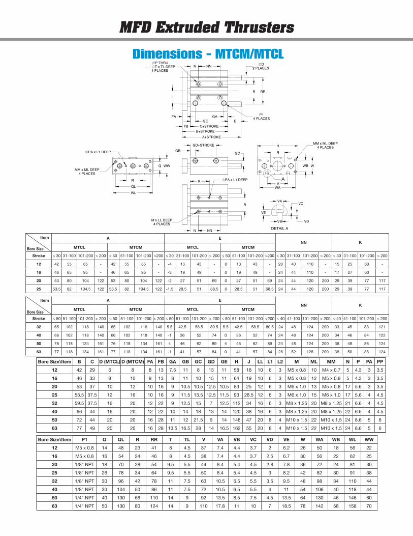
Bore Size\Item B C D (MTCL) D (MTCM) FA FB GA GB GC GD GE H J LL L1 L2 M ML MM N P PA PP
12 42 29 6 8 8 13 7.5 11 8 13 11 58 18 10 6 3 M5 x 0.8 10 M4 x 0.7 5 4.3 3 3.5
16 46 33 8 10 8 13 8 11 10 15 11 64 19 10 6 3 M5 x 0.8 12 M5 x 0.8 5 4.3 3 3.5
20 53 37 10 12 10 16 9 10.5 10.5 12.5 10.5 83 25 12 6 3 M6 x 1.0 13 M5 x 0.8 17 5.6 3 3.5
25 53.5 37.5 12 16 10 16 9 11.5 13.5 12.5 11.5 93 28.5 12 6 3 M6 x 1.0 15 M6 x 1.0 17 5.6 4 4.5
32 59.5 37.5 16 20 12 22 9 12.5 15 7 12.5 112 34 16 6 3 M8 x 1.25 20 M8 x 1.25 21 6.6 4 4.5
40 66 44 16 20 12 22 10 14 18 13 14 120 38 16 6 3 M8 x 1.25 20 M8 x 1.25 22 6.6 4 4.5
50 72 44 20 20 16 28 11 12 21.5 9 14 148 47 20 8 4 M10 x 1.5 22 M10 x 1.5 24 8.6 5 6
63 77 49 20 20 16 28 13.5 16.5 28 14 16.5 162 55 20 8 4 M10 x 1.5 22 M10 x 1.5 24 8.6 5 6
Bore Size\Item P1 Q QL R RR T TL V VA VB VC VD VE W WA WB WL WW
12 M5 x 0.8 14 48 23 41 8 4.5 37 7.4 4.4 3.7 2 6.2 26 50 18 56 22
16 M5 x 0.8 16 54 24 46 8 4.5 38 7.4 4.4 3.7 2.5 6.7 30 56 22 62 25
20 1/8" NPT 18 70 28 54 9.5 5.5 44 8.4 5.4 4.5 2.8 7.8 36 72 24 81 30
25 1/8" NPT 26 78 34 64 9.5 5.5 50 8.4 5.4 4.5 3 8.2 42 82 30 91 38
32 1/8" NPT 30 96 42 78 11 7.5 63 10.5 6.5 5.5 3.5 9.5 48 98 34 110 44
40 1/8" NPT 30 104 50 86 11 7.5 72 10.5 6.5 5.5 4 11 54 106 40 118 44
50 1/4" NPT 40 130 66 110 14 9 92 13.5 8.5 7.5 4.5 13.5 64 130 46 146 60
63 1/4" NPT 50 130 80 124 14 9 110 17.8 11 10 7 18.5 78 142 58 158 70
Dimensions - MTCM/MTCL
Item A ENN K
MTCL MTCM MTCL MTCM
Stroke ≤ 30 31-100 101-200 > 200 ≤ 50 51-100 101-200 >200 ≤ 30 31-100 101-200 > 200 ≤ 50 51-100 101-200 >200 ≤ 30 31-100 101-200 > 200 ≤ 30 31-100 101-200 > 200
12 42 55 85 - 42 55 85 - -4 13 43 - 0 13 43 - 20 40 110 - 15 25 60 -
16 46 65 95 - 46 65 95 - -3 19 49 - 0 19 49 - 24 44 110 - 17 27 60 -
20 53 80 104 122 53 80 104 122 -2 27 51 69 0 27 51 69 24 44 120 200 29 39 77 117
25 53.5 82 104.5 122 53.5 82 104.5 122 -1.5 28.5 51 68.5 0 28.5 51 68.5 24 44 120 200 29 39 77 117
Item A ENN K
MTCL MTCM MTCL MTCM
Stroke ≤ 50 51-100 101-200 > 200 ≤ 50 51-100 101-200 > 200 ≤ 50 51-100 101-200 > 200 ≤ 50 51-100 101-200 >200 ≤ 40 41-100 101-200 > 200 ≤ 40 41-100 101-200 > 200
32 65 102 118 140 65 102 118 140 5.5 42.5 58.5 80.5 5.5 42.5 58.5 80.5 24 48 124 200 33 45 83 121
40 66 102 118 140 66 102 118 140 -1 36 52 74 0 36 52 74 24 48 124 200 34 46 84 122
50 76 118 134 161 76 118 134 161 4 46 62 89 4 46 62 89 24 48 124 200 36 48 86 124
63 77 118 134 161 77 118 134 161 -1 41 57 84 0 41 57 84 28 52 128 200 38 50 88 124
Bore Size
Bore Size
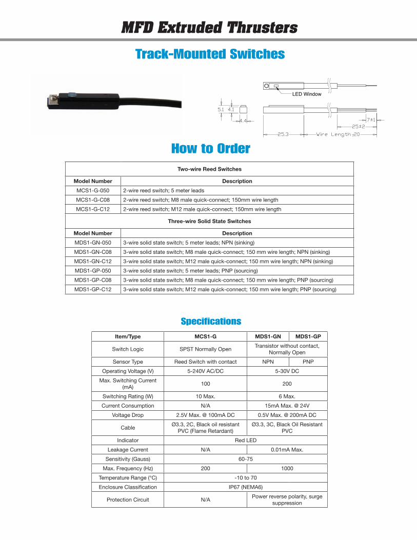
5.1 4.1
4.4
LED Window
25.3
7±125±2
Wire Length 20
Item/Type MCS1-G MDS1-GN MDS1-GP
Switch Logic SPST Normally OpenTransistor without contact,
Normally Open
Sensor Type Reed Switch with contact NPN PNP
Operating Voltage (V) 5-240V AC/DC 5-30V DC
Max. Switching Current (mA)
100 200
Switching Rating (W) 10 Max. 6 Max.
Current Consumption N/A 15mA Max. @ 24V
Voltage Drop 2.5V Max. @ 100mA DC 0.5V Max. @ 200mA DC
CableØ3.3, 2C, Black oil resistant
PVC (Flame Retardant)Ø3.3, 3C, Black Oil Resistant
PVC
Indicator Red LED
Leakage Current N/A 0.01mA Max.
Sensitivity (Gauss) 60-75
Max. Frequency (Hz) 200 1000
Temperature Range (°C) -10 to 70
Enclosure Classification IP67 (NEMA6)
Protection Circuit N/APower reverse polarity, surge
suppression
Two-wire Reed Switches
Model Number Description
MCS1-G-050 2-wire reed switch; 5 meter leads
MCS1-G-C08 2-wire reed switch; M8 male quick-connect; 150mm wire length
MCS1-G-C12 2-wire reed switch; M12 male quick-connect; 150mm wire length
Three-wire Solid State Switches
Model Number Description
MDS1-GN-050 3-wire solid state switch; 5 meter leads; NPN (sinking)
MDS1-GN-C08 3-wire solid state switch; M8 male quick-connect; 150 mm wire length; NPN (sinking)
MDS1-GN-C12 3-wire solid state switch; M12 male quick-connect; 150 mm wire length; NPN (sinking)
MDS1-GP-050 3-wire solid state switch; 5 meter leads; PNP (sourcing)
MDS1-GP-C08 3-wire solid state switch; M8 male quick-connect; 150 mm wire length; PNP (sourcing)
MDS1-GP-C12 3-wire solid state switch; M12 male quick-connect; 150 mm wire length; PNP (sourcing)
MFD Extruded Thrusters
Track-Mounted Switches
How to Order
Specifications
Notes
www.mfdpneumatics.com
© Copyright 2012 Bimba Manufacturing Company. MFD-AP-613 Effective June, 2013. All Rights Reserved.
Bimba Manufacturing Headquarters
P.O. Box 68 Monee, Illinois 60449-0068
Phone: 708-534-8544 Toll Free: 800-44-BIMBA Fax: 708-235-2014
Email: [email protected] www.bimba.com
Your stocking distributor is:
Worldwide distribution means there is a professional stocking
Bimba distributor nearby ready to service your needs.
pneuma tic • electric • hydraulic actua to rs FITTIngs — MAnIFOlds — VAlVEs — AIr PrEPArATIOn — sAFETy & PrOducTIOn
BIMBA BRANDS I MEAD I MFD I PNEUMADYNE I TRD
Mead Fluid Dynamics
4114 north Knox Avenue chicago, Il 60641
Phone: 773-685-6800 Toll Free: 877-MEAd-usA Fax: 773-685-7002
Email: [email protected] www.mead-usa.com