Embed Size (px)
Citation preview
Product CatalogJet PumpsMixers, HeatersVacuum Systems

2

Table of contentsPage Index
Basics and worksheets 5General information on jet pumps 7 abl1Materials table (excerpt) 9 abl1International System of Units 11 abl2Conversion tables for different units of measurement 12 abl2Measurement conversion table, conversion of english-american units in the International System of Units (SI) and vice versa 13 abl3Temperature conversion table, °C in °F and vice versa 14 abl3Water vapor pressure table, vacuum range (saturated steam) 15 abl5Water vapor temperature table, vacuum range (saturated steam) 16 abl5Water vapor pressure table, pressure range 1-70 bar (saturated steam) 17 abl6Water vapor temperature table, temperature range 100-300 °C (saturated steam) 18 abl6Vapors and gases in vacuum 19 abl7Water vapor and air in vacuum 20 abl7Air leakage in vacuum vessels 21 abl8Admissible flow velocity in vacuum ducts 22 abl8Pressure loss in vacuum lines with water vapor 23 abl9Pressure loss in water pipes 24 abl9Dimensions, velocities and mass flows in steam and water pipes 25 abl10Vapor flows in pipes 26 abl10Mass flow of gases and vapors through nozzles 27 abl11Water vapor flow through motive nozzles at critical pressure ratio 28 abl11Equivalent suction flows for steam jet vacuum pumps 29 abl12Steam consumption of jet pumps 31 abl13
Liquid jet pumps 33Liquid jet vacuum pumps, general information 35 fvpoQuestionnaire for liquid jet vacuum pumps, fvp1, fvp2, fvp3 36Liquid jet vacuum pumps with threaded connections 37 fvp1Liquid jet vacuum pumps with flanged connections 39 fvp2Liquid jet vacuum pumps of PTFE 41 fvp3Liquid jet gas compressors 43 fgv1oQuestionnaire for liquid jet gas compressors, fgv1 46Liquid jet liquid pumps, general information 47 wpoQuestionnaire for liquid jet liquid pumps, wp1, wp2, wp3 49Liquid jet liquid pumps of steel or stainless steel 50 wp1Standard liquid jet liquid pumps of PVC/PP 51 wp2Standard liquid jet liquid pumps of PTFE 53 wp3Liquid jet solids pumps 55 wfp1oQuestionnaire for liquid jet solids pumps, wfp1 57Liquid jet mixers 59 fm1oQuestionnaire for liquid jet mixers, fm1, fm2 62Liquid jet mixers for food applications/orbitally welded design 63 fm2Liquid jet ventilators 65 fv1oQuestionnaire for liquid jet ventilators, fv1 67
Steam jet pumps 69Steam jet vacuum pumps 71 dvp1oQuestionnaire for steam jet vacuum pumps, dvp1 75oQuestionnaire for steam jet compressors (thermo compressors), bv1 76Steam jet compressors (thermo compressors) 77 bv1Steam jet ventilators 81 dv1oQuestionnaire for steam jet ventilators, dv1 83Steam jet liquid pumps, general information 85 dfpoQuestionnaire for steam jet liquid pumps, dfp1, dfp2 86Steam jet liquid pumps class A 87 dfp1Steam jet liquid pumps class B 89 dfp2Steam jet heaters, general information 91 awoQuestionnaire for steam jet heaters for vessels, aw1 92Steam jet heaters for vessels 93 aw1Steam jet heaters “L” for installation in pipelines 97 aw4Steam jet heaters “H” for passage and circulation heating systems 99 aw5Steam jet heaters “System Ciba-Geigy” for passage and circulation heating systems 101 aw6oQuestionnaire for steam jet heaters, type “L”, aw4, steam jet heaters, type “H”, aw5, steam jet heaters “System Ciba-Geigy”, aw6 103
Gas/air jet pumps 105Gas jet vacuum pumps and gas jet compressors 107 gp1Air jet vacuum pumps for connections to the suction side of liquid ring vacuum pumps 109 lvp1oQuestionnaire for gas jet vacuum pumps and gas jet compressors, gp1, air jet vacuum pumps, lvp1, gas jet ventilators, gv1 110Gas jet ventilators 111 gv1
Vacuum systems 113Vacuum systems 115 gdp1Multi-stage steam jet vacuum pumps 116 gdp1Multi-stage steam jet vacuum pumps in metal construction with mixing condensers 117 dpm1Multi-stage steam jet vacuum pumps in metal construction with surface condensers 119 dpo1Multi-stage steam jet vacuum pumps in metal construction with liquid ring vacuum pumps (hybrid system) 121 dwp1Multi-stage steam jet vacuum pumps in graphite 123 pgv1Arrangements of steam jet vacuum pumps 125 gdp2Laboratory steam jet vacuum pumps 129 ldp1Planning a steam jet vacuum pump 131 gdp3oQuestionnaire for the planning of a steam jet vacuum pump or a vacuum condensation plant 139

Grundlagen und ArbeitsblätterGrundlagen und ArbeitsblätterBasics and worksheets
• General information on jet pumps
• Materials table (excerpt)
• International System of Units
• Conversion tables for diff erent units of measurement
• Measurement conversion table, conversion of english-american units in the International System of Units (SI) and vice versa
• Temperature conversion table, °C in °F and vice versa
• Water vapor pressure table, vacuum range (saturated steam)
• Water vapor temperature table, vacuum range (saturated steam)
• Water vapor pressure table, pressure range 1-70 bar (saturated steam)
• Water vapor temperature table, temperature range 100-300 °C (saturated steam)
• Vapors and gases in vacuum
• Water vapor and air in vacuum
• Air leakage in vacuum vessels
• Admissible fl ow velocity in vacuum ducts
• Pressure loss in vacuum lines with water vapor
• Pressure loss in water pipes
• Dimensions, velocities and mass fl ows in steam and water pipes
• Vapor fl ows in pipes
• Mass fl ow of gases and vapors through nozzles
• Water vapor fl ow through motive nozzles at critical pressure ratio
• Equivalent suction fl ows for steam jet vacuum pumps
• Steam consumption of jet pumps


7GEA Wiegand GmbH Tel. +49 7243 705-0
Am Hardtwald 1, 76275 Ettlingen, Germany [email protected], gea.com
abl1
18
General information on jet pumps
Jet pumps, also referred to as ejectors, are devices for the conveyance, compression or mixing of gases, vapors, liquids or solids in which a gaseous or liquid medium serves as the motive force. They operate by the con-version of pressure energy into velocity in suitable nozzles. They are “pumps without moving parts”.The basic principle of jet pumps consists in the liquid or gas jet being emitted by a noz-zle at high speed entraining and accelerating the surrounding liquid, gas or solid matter. The result of this action is a mixture of the driving and entrained (sucked) fluids, the velocity of which is reduced and the pres-sure increased in a second nozzle.
The practical application of this principle requires a simple apparatus which essential-ly consists of only 3 main parts (figure 1): • motive nozzle (1)• diffuser (2) • head (3)
The flow channel of the diffuser consists of a part converging in the direction of the flow (the inlet cone), a cylindrical piece (the throat) and a diverging part (the out-let cone). The pressures at the connections and the corresponding mass flows determine the functional effect of a jet pump.
A jet pump is provided with at least 3 con-nections (figure 1): • motive medium inlet connection (A)• suction manifold (B)• pressure manifold (C)
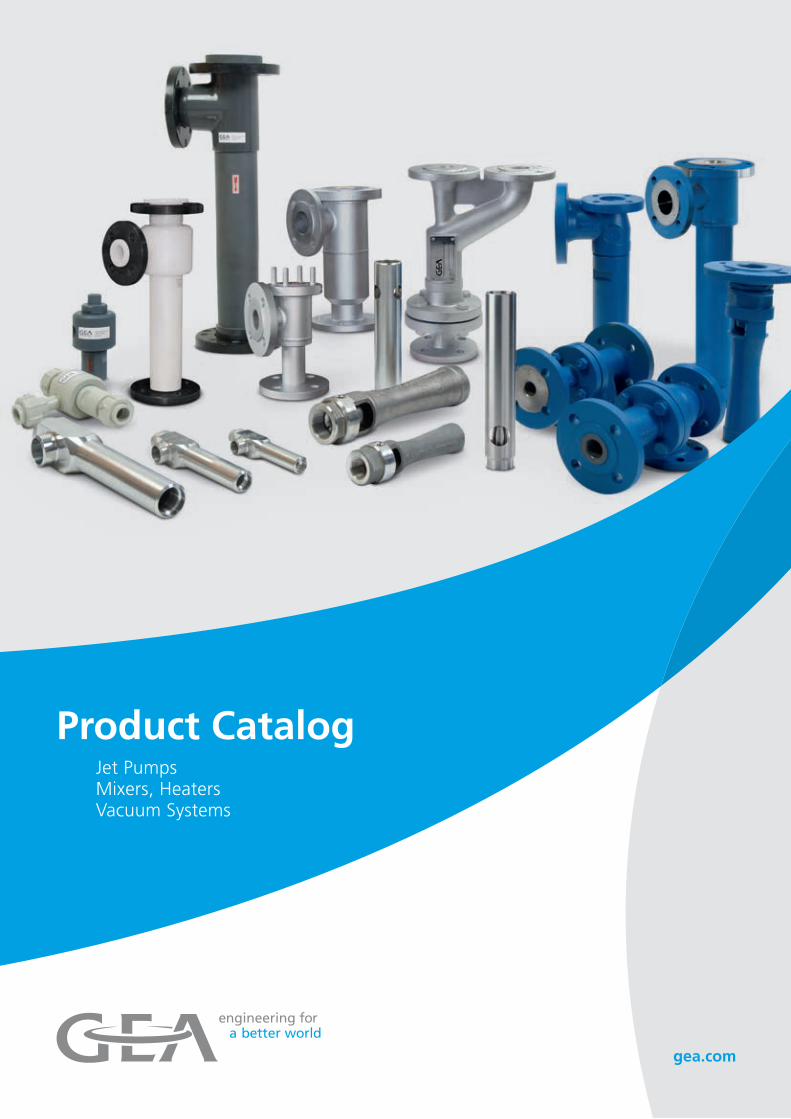
The pressures prevailing there are as follows (figure 2):p1 pressure upstream of the motive nozzle =
motive medium pressurep0 pressure at the suction manifold = suction pressurep pressure at the outlet manifold = discharge pressure
The mass flows Ø1, Ø0 and Ø for the enter-ing and exiting fluids are measured in kg/h. For this purpose, the following equation shall apply: Ø1 + Ø0 = Ø.
For the relationship between the various pressures, no simple rule can be applied. The internal processes in jet pumps are complex and only in a limited way accessible by cal-culation.
FIG. 1
FIG. 2
DESIGNATIONS OF JET PUMPS
The terms of jet pumps (ejectors) are defined in DIN 24290. According to DIN 24290, jet pumps are named according to the motive side and to the suction side. The designations in this catalog follow this standard.
ACCORDING TO THE
SUCTION SIDE
ACCORDING TO THE MOTIVE SIDE
GAS JET PUMP STEAM JET PUMP LIQUID JET PUMP
Jet ventilator Gas jet ventilator Steam jet ventilator Liquid jet ventilator
Jet compressor Gas jet compressor Steam jet compressor
(Vapor recompressor)
Liquid jet compressor
Jet vacuum pump Gas jet vacuum pump Steam jet vacuum pump Liquid jet vacuum pump
Jet liquid pump Gas jet liquid pump Steam jet liquid pump Liquid jet liquid pump
Jet solids pump Gas jet solids pump Steam jet solids pump Liquid jet solids pump
The designation of the individual parts of a jet pumps is standardized according to DIN 24 291.

8 GEA Wiegand GmbH Tel. +49 7243 705-0
Am Hardtwald 1, 76275 Ettlingen, Germany [email protected], gea.com
abl1
18
General information on jet pumps
SCOPE OF DELIVERY
The scope of delivery of the jet pumps department of GEA Wiegand is divided into two main fields.
1) DELIVERY OF STANDARD APPARATUSES
This catalog gives a wide selection. The types and sizes are selected such that for usual tasks a suitable unit can always be found. Description and capacity curves and the corresponding sheets allow the correct choice.
2) DESIGN, CONSTRUCTION AND DELIVERY OF
SPECIAL APPARATUSES AND PLANTS
For this purpose our well-trained staff of specialists in jet pumps and vacuum sys-tems is available. In our modern Research Laboratory, the required analyses, research work and tests are carried out. Special leaf-lets give detailed information; they show the general principles of these plants and inform the customers which data are needed for engineering and for the preparation of a
quotation. Jet pumps can be built for very small as well as for extraordinarily large capacities. They can be constructed from most different materials and stand out for the following features:
• reliability • simplicity• low maintenance costs • low acquisition costs
WHAT HAS TO BE BORNE IN MIND?
WHEN PURCHASING JET PUMPS ACCORDING TO THE
CATALOG:
• The capacities specified in the catalog
sheets are only approximate values. They will be different if operating conditions change.
• For the design in individual cases, our order confirmation is binding and not the catalog sheet.
• Where necessary, installation and operat-ing instructions are made available.
• Normally, cast apparatuses are supplied with flanges bored to DIN PN 10, unless otherwise agreed. If specified, flanges according to ASME, BS or other special flanges can be supplied, if the casting model is available or if it is a question of welded (fabricated) apparatus. Counter flanges together with seals and screws are only supplied on request.
• Our General Sales Conditions are valid for all supplies.
WHEN INSTALLING JET PUMPS:
• Do not mix up connections.
• Connecting pipe lines must be of equal or larger diameter than the corresponding connections on the plant.
• Valves, fittings, seals etc. must have the full cross sectional area and not restrict the line.
• For longer pipe lines, the cross sectional area must be larger to obtain the lowest possible pressure loss. In all cases, care must be taken to ensure that the pipe line be constructed with the most favourable flow characteristics.
• Steam lines should be well insulated. Dry motive steam is particularly important for the good operation of steam jet vacuum pumps.
• Before the first start-up the lines should be blasted and cleaned with steam or com-pressed air. Otherwise, rust, dirt and weld-ing beads can easily block the nozzles of the pumps.
• Furthermore, we recommend the installa-tion of a dirt trap in the supply lines for motive fluids.
• For further details on the assembly and operation of jet pumps please refer to the respective operation instructions.

9GEA Wiegand GmbH Tel. +49 7243 705-0
Am Hardtwald 1, 76275 Ettlingen, Germany [email protected], gea.com
abl1
18
Materials table (excerpt)
Availability on request
Material no. Short name acc. to EN 10088-2 AISI/ASTM/UNS-Type UNS
1.0038 S235JRG2 (RSt 37.2) A570 Gr. 36 K03000
1.0425 P265GH A516 Gr. 60 K02505
1.0566 P355NL1 K02701
1.4016 X 6 Cr 17 430 S43000
1.4113 X6CrMo17-1 434 S43400
1.4301 X5CrNi18-10 304 S30400
1.4306 X2CrNi19-11 304L S30403
1.4307 X2CrNi18-9 304L S30403
1.4401 X5CrNiMo17-12-2 316 S31600/S31609
1.4404 X2CrNiMo17-12-2 316L S31603
1.4435 X2CrNiMo18-14-3 316L S31603
1.4436 X3CrNiMo17-13-3 316 S31600
1.4439 X2CrNiMoN17-13-5 317LMN S31726
1.4462 X2CrNiMoN22-5-3 318LN S31803
1.4529 X1NiCrMoCuN25-20-7 926 N08926
1.4539 X1NiCrMoCuN25-20-5 904L N08904
1.4541 X6CrNiTi18-10 321 S32100
1.4550 X6CrNiNb18-10 347 S34700
1.4571 X6CrNiMoTi17-12-2 316Ti S31635
1.4581 GX5CrNiMoNb19-11-2
1.4828 X15CrNiSi20-12 309 S30900
1.5415 16Mo3 A204 Gr. A / 4017 K11820

18 10 GEA Wiegand GmbH Tel. +49 7243 705-0
Am Hardtwald 1, 76275 Ettlingen, Germany [email protected], gea.com

11GEA Wiegand GmbH Tel. +49 7243 705-0
Am Hardtwald 1, 76275 Ettlingen, Germany [email protected], gea.com
abl2
18
International System of Units
The units for measurement and weight are in accordance with the International System of Units (SI) recommended by the International Organisation of Stand-ardisation (ISO).
For the technical range which is the subject matter of this catalog, the following basic units of measurement and the corresponding abbreviations, taken from the International System of Units, shall apply.
Basic parameter Basic unit Abbre-viation
Length meter m
Mass kilogramme kg
Time second s
Temperature kelvin K
Amperage ampere A
Amount of substance mole mol
Basic parameter
Basic unit Abbreviation
Force newton N
Pressure pascal Pa
Energy joule J
Power watt W
THE MOST IMPORTANT OF THE DERIVED UNITS ARE:
The interdependence between derived units and basic units is as follows:
Technical system of units
not allowed since 1.1.1978
Conversion International system of units (SI)
newly introduced since 1.1.1978
Pressure 1 kp/m2 = 1 mm WC
1 ata
1 Torr
1 m WC
1 kp/m2 = 0.098067 · 10-3 bar
1 ata = 0.98067 bar
1 Torr = 1.3332 · 10-3 bar
1 m WC = 0.098067 bar
1 bar = 105 Pa
1 mbar = 102 Pa = 1 hPa
10-2 mbar = 1 Pa
Energy
Work
1 kp m
1 kcal
1 kp m = 9.8067 J
1 kcal = 4.1868 kJ
1 J = 10-3 kJ
1 J = 1 Nm
Power 1 PS
1 kcal/h
1 PS = 0.7355 kW
1 kcal/h = 1.163 W
1 W = 10-3 kW
Heat transfer /
Heat transmission
Thermal conductivity
Specific heat
capacity
The table Conversion from technical system of units to international system of units shows a comparison between the earlier used Technical System of Units and the newly, legally binding, introduced International System of Units for the most important values given in this catalog.
p pico 10-12
n nano 10-9
μ mikro 10-6
m milli 10-3
c centi 10-2
d deci 10-1
D deca 101
h hecto 102
k kilo 103
M mega 106
G giga 109
T tera 1012
The following attachments denote decimal multiples and fractions of the SI-Units.
The unit of thermodynamic temperature is the kelvin in K. The kelvin converted to the Celsius temperature scale has the special name of degree Celsius in °C. Temperature differences are indicated in K or in °C.0 K correspond to -273.10 °C (degrees Cel-sius). The graduation within the two scales is equal: one kelvin step corresponds to one Celsius step.

12 GEA Wiegand GmbH Tel. +49 7243 705-0
Am Hardtwald 1, 76275 Ettlingen, Germany [email protected], gea.com
The following tables show the units of measurement for pressure, energy and capacity in use ever since in comparison to the units of the international system of units (SI).
Conversion tables for different units of measurementab
l2 1
8
PRESSURE, DEFINITION OF TERMS AND UNITS
In technology, various units of pressure are used. A differentiation is made between absolute pressure, differential pressure and gauge pressure.
ABSOLUTE PRESSURE pabs. takes as its basis zero pressure of a pure vacuum.
DIFFERENTIAL PRESSURE Δp is the difference between two pressures.
GAUGE PRESSURE pe is the difference between an absolute pressure pabs. and the actual (absolute) atmospheric pressure pamb..
pe = pabs. – pamb.
Pressure gauge pe will have a positive value if the absolute pressure is greater than atmospheric pressure and it will have a negative value if the absolute pressure is smaller than atmospheric pressure.
“Negative Pressure” may no longer be used as a designation of a parameter, but only as a qualitative term for a condition, e.g. “A negative pressure prevails in the suction line”.
The indices used are derived from the Latin words:
abs = absolutus; detached, independent
amb = ambiens; environs, ambient
e = excedens; exceed
(see also DIN 1314 “Pressure, basic defini-tions and units”)
The unit of pressure is the pascal in Pa. For practical purposes the bar (1 bar = 105 Pa) is used as a convenient unit for calculation.The range of pressure below atmospheric pressure is also be called the vacuum range. In vacuum technology absolute pressure is always used.
PRESSURE UNITS
ENERGY UNITS
CAPACITY UNITS
Pa = N/m² bar at mm WC atm Torr psia
1 Pa = 1 N/m² 1 10-5 1.0197 · 10-5 0.10197 0.9869 · 10-5 0.75006 · 10-2 1.45037 · 10-4
1 bar = 1000 mbar 105 1 1.0197 1.0197 · 104 0.9869 0.75006 · 103 14.5037
1 mbar 102 1 ·10-3 1.0197 · 10-3 10.197 0.9869 · 10-3 0.75006 1.45037 · 10-2
1 at 0.98067 · 105 0.98067 1 1.00003 · 104 0.96784 0.73556 · 103 14.224
1 mm WC 9.8064 0.98064 · 10-4 0.99997 · 10-4 1 0.96781 · 10-4 0.73554 · 10-1 1.4224 · 10-3
1 atm 1.01325 · 105 1.01325 1.03323 1.03326 · 104 1 760 14.696
1 Torr 1.3332 · 102 1.3332 · 10-3 1.3595 · 10-3 13.595 1.3158 · 10-3 1 1.9336 · 10-2
1 psia 6.8948 · 103 6.8948 · 10-2 7.0306 · 10-2 7.0306 · 102 6.8043 · 10-2 51.716 1
kJ kWh kpm kcal Btu
1 kJ 1 2.7778 · 10-4 1.0197 · 102 0.23884 0.9478
1 kWh 3.6000 · 103 1 3.6710 · 105 8.598 · 102 3.4120 · 103
1 kpm 9.8067 · 10-3 2.7241 · 10-6 1 2.3422 · 10-3 9.2945 · 10-3
1 kcal 4.1868 1.1630 · 10-3 4.2694 · 102 1 3.96825
1 Btu 1.0551 2.9308 · 10-4 1.0759 · 102 0.2520 1
kW kpm/s PS kcal/s kcal/h
1kW 1 1.0197 · 102 1.3596 0.23884 859.824
1 kpm/s 9.80665 · 10-3 1 1.3333 · 10-2 2.3422 ·10-3 8.4319
1 PS 0.7355 75 1 1.7573 · 10-1 6.3263 · 102
1 kcal/s 4.1868 4.2694 · 102 5.692 1 3.6 · 103
1 kcal/h 1.163 · 10-3 1.1859 · 10-1 1.5811 · 10-3 2.7778 · 10-4 1

13GEA Wiegand GmbH Tel. +49 7243 705-0
Am Hardtwald 1, 76275 Ettlingen, Germany [email protected], gea.com
Length
1 mm
1 m
1 m
0.0394 in
3.28 ft
1.093 yd
Area
1 cm2
1 dm2
0.155 in2
0.1076 ft2
Volume
1 cm3
1 dm3
1 ltr.
1 ltr.
0.061 in3
0.0353 ft3
0.22 lmp. gal
0.264 U.S. gal
Mass
1 g
1 kg
1 t
1 t
0.0353 oz
2.205 lb
1.1023 U.S. ton
0.984 Brit.ton
Density
1 kg/m3 0.0624 lb/ft3
Temperature
1 °C
1 K
9/5 °F
9/5 °F
Pressure
1 bar
1 bar
14.5 lbf/in2
20.88 lbf/ft2
Measurement conversion tableConversion of english-american units in the International System of Units (SI) and vice versa
abl3
18
Heat / heat units
1 Btu 1.055 kJ
Heat capacity
Specific heat capacity
Thermal conductivity
Heat transfer
Fouling factor
Heat flux density
Heat / heat units
1 kJ 0.948 Btu
Heat capacity
Specific heat capacity
Thermal conductivity
Heat transfer
Fouling factor
Heat flux density
English- american units
Internat.system of units
English- american units
Internat.system of units
Internat.system of units
English- american units
English- american units
Internat.system of units
Length
1 in
1 ft (12 in)
1 yd (3 ft)
25.4 mm
0.305 m
0.914 m
Area
1 in2
1 ft2
6.45 cm2
9.29 dm2
Volume
1 in3
1 ft3
1 lmp. gal
1 U.S. gal
16.4 cm3
28.3 dm3
4.55 ltr.
3.785 ltr.
Mass
1 oz
1 lb (16 oz)
1 U.S. ton
1 Brit. ton
28.35 g
0.454 kg
0.907 t
1.016 t
Density
1 lb/ft3 16.02 kg/m3
Temperature
1 °F
1 °F
5/9 °C
5/9 K
Pressure
1 lbf/in2 (psi)
1 lbf/ft2
6.895 · 10-2 bar
4.788 · 10-4 bar
14 GEA Wiegand GmbH Tel. +49 7243 705-0
Am Hardtwald 1, 76275 Ettlingen, Germany [email protected], gea.com
Temperature conversion table°C in °F and vice versa
abl3
18
°C °F
– 28.8 – 20 – 4.0– 28.3 – 19 – 2.2
– 27.7 – 18 – 0.4
– 27.2 – 17 1.4
– 26.6 – 16 3.2
– 26.1 – 15 5.0
– 25.5 – 14 6.8
– 25.0 – 13 8.6
– 24.4 – 12 10.4
– 23.8 – 11 12.2
– 23.3 – 10 14.0
– 22.7 – 9 15.8
– 22.2 – 8 17.6
– 21.6 – 7 19.4
– 21.1 – 6 21.2
– 20.5 – 5 23.0
– 20.0 – 4 24.8
– 19.4 – 3 26.6
– 18.8 – 2 28.4
– 18.3 – 1 30.2
– 17.7 0 32.0
– 17.2 1 33.8
– 16.6 2 35.6
– 16.1 3 37.4
– 15.5 4 39.2
– 15.0 5 41.0
– 14.4 6 42.8
– 13.8 7 44.6
– 13.3 8 46.4
– 12.7 9 48.2
– 12.2 10 50.0
– 11.6 11 51.8
– 11.1 12 53.6
– 10.5 13 55.4
– 10.0 14 57.2
– 9.4 15 59.0
– 8.8 16 60.8
– 8.3 17 62.6
– 7.7 18 64.4
– 7.2 19 66.2
– 6.6 20 68.0
– 6.1 21 69.8
– 5.5 22 71.6
– 5.0 23 73.4
– 4.4 24 75.2
– 3.8 25 77.0
– 3.3 26 78.8
– 2.7 27 80.6
– 2.2 28 82.4
– 1.6 29 84.2
– 1.1 30 86.0
– 0.5 31 87.8
0.0 32 89.6
0.5 33 91.4
1.1 34 93.2
1.6 35 95.0
2.2 36 96.8
2.7 37 98.6
3.3 38 100.4
3.8 39 102.2
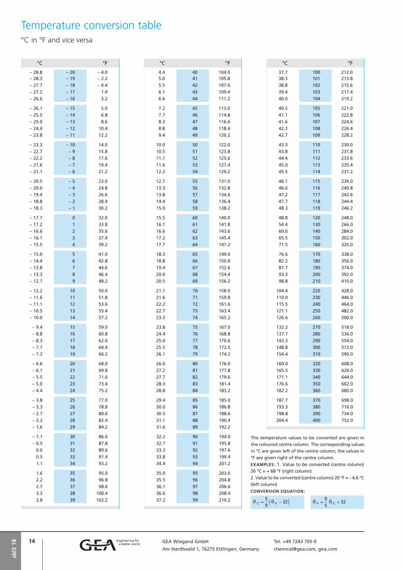
The temperature values to be converted are given in
the coloured centre column. The corresponding values
in °C are given left of the centre column, the values in
°F are given right of the centre column.
EXAMPLES: 1. Value to be converted (centre column)
20 °C = + 68 °F (right column)
2. Value to be converted (centre column) 20 °F = – 6.6 °C
(left column)
CONVERSION EQUATION:
°C °F
4.4 40 104.05.0 41 105.8
5.5 42 107.6
6.1 43 109.4
6.6 44 111.2
7.2 45 113.0
7.7 46 114.8
8.3 47 116.6
8.8 48 118.4
9.4 49 120.2
10.0 50 122.0
10.5 51 123.8
11.1 52 125.6
11.6 53 127.4
12.2 54 129.2
12.7 55 131.0
13.3 56 132.8
13.8 57 134.6
14.4 58 136.4
15.0 59 138.2
15.5 60 140.0
16.1 61 141.8
16.6 62 143.6
17.2 63 145.4
17.7 64 147.2
18.3 65 149.0
18.8 66 150.8
19.4 67 152.6
20.0 68 154.4
20.5 69 156.2
21.1 70 158.0
21.6 71 159.8
22.2 72 161.6
22.7 73 163.4
23.3 74 165.2
23.8 75 167.0
24.4 76 168.8
25.0 77 170.6
25.5 78 172.5
26.1 79 174.2
26.6 80 176.0
27.2 81 177.8
27.7 82 179.6
28.3 83 181.4
28.8 84 183.2
29.4 85 185.0
30.0 86 186.8
30.5 87 188.6
31.1 88 190.4
31.6 89 192.2
32.2 90 194.0
32.7 91 195.8
33.3 92 197.6
33.8 93 199.4
34.4 94 201.2
35.0 95 203.0
35.5 96 204.8
36.1 97 206.6
36.6 98 208.4
37.2 99 210.2
°C °F
37.7 100 212.038.3 101 213.8
38.8 102 215.6
39.4 103 217.4
40.0 104 219.2
40.5 105 221.0
41.1 106 222.8
41.6 107 224.6
42.2 108 226.4
42.7 109 228.2
43.3 110 230.0
43.8 111 231.8
44.4 112 233.6
45.0 113 235.4
45.5 114 237.2
46.1 115 239.0
46.6 116 240.8
47.2 117 242.6
47.7 118 244.4
48.3 119 246.2
48.8 120 248.0
54.4 130 266.0
60.0 140 284.0
65.5 150 302.0
71.5 160 320.0
76.6 170 338.0
82.2 180 356.0
87.7 190 374.0
93.3 200 392.0
98.8 210 410.0
104.4 220 428.0
110.0 230 446.0
115.5 240 464.0
121.1 250 482.0
126.6 260 500.0
132.2 270 518.0
137.7 280 536.0
143.3 290 554.0
148.8 300 572.0
154.4 310 590.0
160.0 320 608.0
165.5 330 626.0
171.1 340 644.0
176.6 350 662.0
182.2 360 680.0
187.7 370 698.0
193.3 380 716.0
198.8 390 734.0
204.4 400 752.0

15GEA Wiegand GmbH Tel. +49 7243 705-0
Am Hardtwald 1, 76275 Ettlingen, Germany [email protected], gea.com
Water vapor pressure table Vacuum range (saturated steam)
abl5
18
pmbar
J°C
v”m3/kg
h”kJ/kg
Δhv
kJ/kg
0.001 -76.19 909000 2344 28520.002 -71.74 465000 2355 28510.003 -69.04 314000 2361 28500.004 -67.08 238000 2365 2850
0.005 -65.53 192000 2368 28490.006 -64.25 160700 2371 28490.007 -63.15 138500 2374 28490.008 -62.19 121700 2376 28480.009 -61.34 108600 2377 2848
0.01 -60.57 98110 2379 28480.02 -55.37 50250 2390 28470.03 -52.20 33990 2397 28460.04 -49.90 25760 2402 2845
0.05 -48.08 20770 2405 28440.06 -46.57 17430 2408 28440.07 -45.28 15020 2411 28440.08 -44.14 13210 2413 28430.09 -43.14 11790 2415 2843
0.1 -42.23 10660 2417 28430.2 -36.06 5471 2430 28410.3 -32.29 3705 2437 28400.4 -29.55 2811 2442 2839
0.5 -27.38 2269 2447 28380.6 -25.57 1904 2450 28380.7 -24.02 1643 2453 28380.8 -22.67 1445 2456 28370.9 -21.46 1291 2458 2837
1 -20.36 1167 2460 28371.5 -16.07 791 2469 28362 -12.94 600 2475 28352.5 -10.45 485 2479 28343 -8.38 407 2483 2834
3.5 -6.61 351 2487 28334 -5.06 309 2490 28334.5 -3.67 276 2492 28335 -2.42 250 2495 28335.5 -1.27 228 2497 2832
6 -0.22 210 2499 28327 1.89 181 2505 24978 3.77 160 2509 24939 5.46 143 2512 2489
10 6.98 129 2515 248511 8.38 118 2517 248212 9.66 109 2519 247913 10.86 101 2522 247614 11.98 94.0 2524 2474
15 13.03 88.0 2526 247116 14.02 82.8 2527 246917 14.96 78.2 2529 246718 15.85 74.1 2531 246419 16.70 70.4 2532 2462
20 17.51 67.1 2534 246021 18.28 64.0 2535 245922 19.03 61.3 2537 245723 19.74 58.7 2538 245524 20.43 56.4 2539 2454
25 21.09 54.3 2540 245226 21.73 52.3 2542 245127 22.35 50.5 2543 244928 22.95 48.8 2544 244829 23.53 47.2 2545 2446
30 24.10 45.7 2546 244531 24.64 44.3 2547 244432 25.18 43.0 2548 244233 25.69 41.8 2549 244134 26.20 40.6 2550 2440
pmbar
J°C
v”m3/kg
h”kJ/kg
Δhv
kJ/kg
35 26.69 39.5 2551 243936 27.17 38.5 2551 243837 27.64 37.5 2552 243738 28.10 36.6 2553 243539 28.54 35.7 2554 2434
40 28.98 34.8 2555 243342 29.83 33.3 2556 243144 30.64 31.8 2558 242946 31.42 30.5 2559 242848 32.17 29.3 2560 2426
50 32.90 28.2 2562 242452 33.60 27.2 2563 242254 34.27 26.2 2564 242156 34.93 25.4 2565 241958 35.57 24.5 2567 2418
60 36.18 23.8 2568 241662 36.78 23.0 2569 241564 37.37 22.4 2570 241366 37.93 21.7 2571 241268 38.49 21.1 2572 2411
70 39.03 20.5 2573 240972 39.55 20.0 2574 240874 40.06 19.5 2575 240776 40.57 19.0 2575 240678 41.06 18.6 2576 2404
80 41.54 18.1 2577 240385 42.69 17.1 2579 240190 43.79 16.2 2581 239895 44.84 15.4 2583 2395
100 45.84 14.7 2585 2393110 47.71 13.4 2588 2388120 49.45 12.4 2591 2384130 51.06 11.5 2594 2380140 52.58 10.7 2597 2377
150 54.00 10.0 2599 2373160 55.34 9.44 2602 2370170 56.62 8.92 2604 2367180 57.83 8.45 2606 2364190 58.99 8.03 2608 2361
200 60.09 7.65 2610 2358220 62.17 7.00 2613 2353240 64.09 6.45 2617 2348260 65.88 5.98 2620 2344280 67.55 5.58 2623 2340
300 69.13 5.23 2625 2336320 70.62 4.93 2628 2332340 72.03 4.65 2630 2329360 73.38 4.41 2633 2325380 74.66 4.19 2635 2322
400 75.89 4.00 2637 2319420 77.07 3.82 2639 2316440 78.20 3.65 2641 2313460 79.29 3.51 2642 2311480 80.33 3.37 2644 2308
500 81.35 3.24 2646 2305550 83.74 2.97 2650 2299600 85.96 2.73 2653 2294650 88.02 2.54 2657 2288700 89.96 2.37 2660 2283
750 91.78 2.22 2663 2279800 93.51 2.09 2666 2274850 95.15 1.97 2668 2270900 96.71 1.87 2671 2266950 98.20 1.78 2673 2262
1000 99.63 1.70 2675 2258
Documentation:1. “Thermodynamische Diagramme” Z. Kältetechnik, 17. (1965) S. 299-3012. VDI Water vapor tables

16 GEA Wiegand GmbH Tel. +49 7243 705-0
Am Hardtwald 1, 76275 Ettlingen, Germany [email protected], gea.com
Water vapor temperature table Vacuum range (saturated steam)
abl5
18
J°C
pmbar
v”m3/kg
h”kJ/kg
Δhv
kJ/kg
-74 0.001411 651700 2349.3 2851.2-73 0.001647 561000 2351.6 2851.0-72 0.001920 483600 2353.9 2850.7-71 0.002236 417500 2356.1 2850.5-70 0.002598 361100 2358.4 2850.3
-69 0.003015 312600 2360.6 2850.0-68 0.003495 271100 2362.8 2849.8-67 0.004044 235400 2365.0 2849.6-66 0.004672 204700 2367.2 2849.3-65 0.005391 178300 2369.4 2849.1
-64 0.006212 155500 2371.6 2848.8-63 0.007149 135800 2373.8 2848.5-62 0.008215 118700 2376.0 2848.3-61 0.00929 103900 2378.1 2848.0-60 0.01080 91100 2380.3 2847.7
-59 0.01237 79900 2382.4 2847.5-58 0.01414 70300 2384.5 2847.2-57 0.01614 61600 2386.7 2846.9-56 0.01841 54500 2388.8 2846.6-55 0.02097 48000 2390.9 2846.4
-54 0.02385 42400 2393.0 2846.1-53 0.02711 37500 2395.1 2845.8-52 0.03077 33200 2397.2 2845.5-51 0.03488 29400 2399.3 2845.2-50 0.03949 26100 2401.3 2844.9
-49 0.04467 23200 2403.4 2844.6-48 0.05047 20600 2405.5 2844.4-47 0.05696 18300 2407.5 2844.1-46 0.06422 16300 2409.6 2843.8-45 0.07232 14600 2411.6 2843.5
-44 0.08136 13000 2413.6 2843.2-43 0.09144 11600 2415.7 2842.9-42 0.1026 10400 2417.7 2842.6-41 0.1151 9312 2419.7 2842.3-40 0.1289 8347 2421.7 2842.0
-39 0.1443 7489 2423.7 2841.7-38 0.1614 6726 2425.7 2841.4-37 0.1803 6046 2427.7 2841.1-36 0.2012 5441 2429.7 2840.8-35 0.2244 4900 2431.7 2840.6
-34 0.2500 4416 2433.7 2840.3-33 0.2783 3985 2435.7 2840.0-32 0.3095 3598 2437.6 2839.7-31 0.3438 3252 2439.6 2839.4-30 0.3816 2942 2441.6 2839.1
-29 0.4233 2663 2443.5 2838.8-28 0.4691 2413 2445.5 2838.6-27 0.5194 2188 2447.4 2838.3-26 0.5746 1986 2449.4 2838.0-25 0.6351 1804 2451.3 2837.7
-24 0.7014 1840 2453.3 2837.5-23 0.7741 1492 2455.2 2837.2-22 0.8536 1358 2457.1 2836.9-21 0.9407 1237 2459.1 2836.7-20 1.035 1129 2461.0 2836.4
-19 1.139 1030 2462.9 2836.2-18 1.252 940.9 2464.8 2835.9-17 1.375 859.9 2466.8 2835.7-16 1.509 786.5 2468.7 2835.4-15 1.656 719.8 2470.6 2835.2
-14 1.815 659.3 2472.5 2835.0-13 1.968 604.2 2474.4 2834.7-12 2.176 554.2 2476.3 2834.5-11 2.380 508.6 2478.3 2834.3-10 2.601 467.1 2480.2 2834.1
-9 2.841 429.3 2482.1 2833.9-8 3.101 394.8 2484.0 2833.7-7 3.363 363.3 2485.9 2833.5-6 3.688 334.5 2487.8 2833.3-5 4.017 308.2 2489.7 2833.1
-4 4.373 284.2 2491.6 2832.9-3 4.758 262.1 2493.5 2832.7-2 5.173 242.0 2495.4 2832.5-1 5.622 223.5 2497.3 2832.40 6.105 206.6 2501.6 2501.6
J°C
pmbar
v”m3/kg
h”kJ/kg
Δhv
kJ/kg
1 6.566 192.6 2503.4 2499.22 7.054 179.9 2505.2 2496.83 7.574 168.2 2507.1 2494.54 8.128 157.3 2508.9 2492.15 8.718 147.2 2510.7 2489.7 6 9.345 137.8 2512.6 2487.47 10.01 129.1 2514.4 2485.08 10.71 121.0 2516.2 2482.69 11.47 113.4 2518.1 2480.3
10 12.27 106.4 2519.9 2477.9
11 13.11 99.91 2521.7 2475.512 14.01 93.84 2523.6 2473.213 14.96 88.18 2525.4 2470.814 15.97 82.90 2527.2 2468.515 17.03 77.98 2529.1 2466.1
16 18.16 73.38 2530.9 2463.817 19.36 69.09 2532.7 2461.418 20.62 65.09 2534.5 2459.019 21.95 61.34 2536.4 2456.720 23.36 57.84 2538.2 2454.3
21 24.85 54.56 2540.0 2452.022 26.41 51.49 2541.8 2449.623 28.07 48.62 2543.6 2447.224 29.82 45.93 2545.5 2444.925 31.65 43.40 2547.3 2442.5
26 33.59 41.03 2549.1 2440.227 35.63 38.81 2550.9 2437.828 37.78 36.73 2552.7 2435.429 40.04 34.77 2554.5 2433.130 42.41 32.93 2556.4 2430.7
31 44.91 31.20 2558.2 2428.332 47.53 29.57 2560.0 2425.933 50.28 28.04 2561.8 2423.634 53.18 26.60 2563.6 2421.235 56.21 25.24 2565.4 2418.8
36 59.39 23.97 2567.2 2416.437 62.74 22.76 2569.0 2414.138 66.24 21.63 2570.8 2411.739 69.91 20.56 2572.6 2409.340 73.74 19.55 2574.4 2406.9
41 77.77 18.59 2576.2 2404.542 81.98 17.69 2577.9 2402.143 86.38 16.84 2579.7 2399.744 90.99 16.04 2581.5 2397.345 95.82 15.28 2583.3 2394.9
46 100.8 14.56 2585.1 2392.547 106.1 13.68 2586.9 2390.148 111.6 13.23 2588.6 2387.749 117.3 12.62 2590.4 2385.350 123.3 12.05 2592.2 2382.9
52 136.1 10.98 2595.7 2378.154 150.0 10.02 2599.2 2373.256 165.1 9.159 2602.7 2368.458 181.4 8.381 2606.2 2363.560 199.2 7.679 2609.7 2358.6
62 218.3 7.044 2613.2 2353.764 239.0 6.469 2616.6 2348.866 261.5 5.948 2620.1 2343.968 285.6 5.476 2623.5 2338.970 311.6 5.046 2626.9 2334.0
72 339.6 4.656 2630.3 2329.074 369.6 4.300 2633.7 2324.076 401.8 3.976 2637.1 2318.978 436.4 3.660 2840.4 2313.980 473.5 3.409 2643.8 2308.8
82 513.2 3.162 2647.1 2303.884 555.7 2.935 2650.4 2298.786 601.0 2.727 2653.6 2293.188 649.4 2.536 2656.9 2288.490 701.0 2.361 2660.1 2283.2
92 756.0 2.200 2663.4 2278.094 814.6 2.052 2666.6 2272.896 876.8 1.915 2669.7 2267.598 943.0 1.789 2672.9 2262.2
100 1013.2 1.673 2676.0 2256.9

17GEA Wiegand GmbH Tel. +49 7243 705-0
Am Hardtwald 1, 76275 Ettlingen, Germany [email protected], gea.com
Water vapor pressure tablePressure range 1-70 bar (saturated steam)
abl6
18
pabs.
bar
J°C
v”m3/kg
h”kJ/kg
Δhv
kJ/kg
1.0 99.63 1.694 2675.4 2257.9
1.1 102.32 1.549 2679.6 2250.8
1.2 104.81 1.428 2683.4 2244.1
1.3 107.13 1.325 2687.0 2237.8
1.4 109.32 1.236 2690.3 2231.9
1.5 111.37 1.159 2693.4 2226.2
1.6 113.32 1.091 2696.2 2220.9
1.7 115.17 1.031 2699.0 2215.7
1.8 116.93 0.9772 2701.5 2210.8
1.9 118.62 0.9290 2704.0 2206.1
2.0 120.23 0.8854 2706.3 2201.6
2.1 121.78 0.8459 2708.5 2197.2
2.2 123.27 0.8098 2710.6 2193.0
2.3 124.71 0.7768 2712.6 2188.9
2.4 126.09 0.7465 2714.5 2184.9
2.5 127.43 0.7184 2716.4 2181.0
2.6 128.73 0.6925 2718.2 2177.3
2.7 129.98 0.6684 2719.9 2173.6
2.8 131.20 0.6460 2721.5 2170.1
2.9 132.39 0.6251 2723.1 2166.6
3.0 133.54 0.6056 2724.7 2163.2
3.2 135.75 0.5700 2727.6 2156.7
3.4 137.86 0.5385 2730.3 2150.4
3.6 139.86 0.5103 2732.9 2144.4
3.8 141.78 0.4851 2735.3 2138.6
4.0 143.62 0.4622 2737.6 2133.0
4.2 145.39 0.4415 2739.8 2127.5
4.4 147.09 0.4226 2741.9 2122.3
4.6 148.73 0.4053 2743.9 2117.2
4.8 150.31 0.3894 2745.7 2112.2
5.0 151.84 0.3747 2747.5 2107.4
5.5 155.46 0.3425 2751.6 2096.0
6.0 158.84 0.3155 2755.5 2085.0
6.5 161.99 0.2925 2758.8 2074.7
7.0 164.96 0.2727 2762.0 2064.9
7.5 167.76 0.2555 2764.9 2055.5
8.0 170.41 0.2403 2767.5 2046.5
8.5 172.93 0.2268 2769.9 2037.8
9.0 175.36 0.2148 2772.1 2029.5
9.5 177.66 0.2040 2774.2 2021.4
10 179.88 0.1943 2776.2 2013.6
11 184.07 0.1774 2779.7 1998.5
12 187.96 0.1632 2782.7 1984.3
13 191.61 0.1511 2785.4 1970.7
14 195.04 0.1407 2787.8 1957.7
15 198.29 0.1317 2789.9 1945.2
16 201.37 0.1237 2791.7 1933.2
17 204.31 0.1166 2793.4 1921.5
18 207.11 0.1103 2794.8 1910.3
19 209.80 0.1047 2796.1 1899.3
pabs.
bar
J°C
v”m3/kg
h”kJ/kg
Δhv
kJ/kg
20 212.37 0.09954 2797.2 1888.6
21 214.85 0.09489 2798.2 1878.2
22 217.24 0.09065 2799.1 1868.1
23 219.55 0.08677 2799.8 1858.2
24 221.78 0.08320 2800.4 1848.5
25 223.94 0.07991 2800.9 1839.0
26 226.04 0.07686 2801.4 1829.6
27 228.07 0.07402 2801.7 1820.5
28 230.05 0.07139 2802.0 1811.5
29 231.97 0.06893 2802.2 1802.6
30 233.84 0.06663 2802.3 1793.9
31 235.67 0.06447 2802.3 1785.4
32 237.45 0.06244 2802.3 1776.9
33 239.18 0.06053 2802.3 1768.6
34 240.88 0.05873 2802.1 1760.3
35 242.54 0.05703 2802.0 1752.2
36 244.16 0.05541 2801.7 1744.2
37 245.75 0.05389 2801.4 1736.2
38 247.31 0.05244 2801.1 1728.4
39 248.84 0.05106 2800.8 1720.6
40 250.33 0.04975 2800.3 1712.9
41 251.80 0.04850 2799.9 1705.3
42 253.24 0.04731 2799.4 1697.8
43 254.66 0.04617 2798.9 1690.3
44 256.05 0.04508 2798.3 1682.9
45 257.41 0.04404 2797.7 1675.6
46 258.75 0.04304 2797.0 1668.3
47 260.07 0.04208 2796.4 1661.1
48 261.37 0.04116 2795.7 1653.9
49 262.65 0.04028 2794.9 1646.8
50 263.91 0.03943 2794.2 1639.7
51 265.15 0.03861 2793.4 1632.7
52 266.37 0.03782 2792.6 1625.7
53 267.58 0.03707 2791.7 1618.8
54 268.76 0.03633 2790.8 1611.9
55 269.93 0.03563 2789.9 1605.0
56 271.09 0.03495 2789.0 1598.2
57 272.22 0.03429 2788.0 1591.4
58 273.35 0.03365 2787.0 1584.7
59 274.46 0.03303 2786.0 1578.0
60 275.55 0.03244 2785.0 1571.3
61 276.63 0.03186 2784.0 1564.7
62 277.70 0.03130 2782.9 1558.0
63 278.75 0.03076 2781.8 1551.5
64 279.79 0.03023 2780.6 1544.9
65 280.82 0.02972 2779.5 1538.4
66 281.84 0.02922 2778.3 1531.9
67 282.84 0.02874 2777.1 1525.4
68 283.84 0.02827 2775.9 1518.9
69 284.82 0.02782 2774.7 1512.5
70 285.79 0.02737 2773.5 1506.0
Documentation: VDI Water vapor tables

18 GEA Wiegand GmbH Tel. +49 7243 705-0
Am Hardtwald 1, 76275 Ettlingen, Germany [email protected], gea.com
Water vapor temperature table Temperature range 100-300 °C (saturated steam)
abl6
18
J°C
T
K
pbar
v”m3/kg
h”kJ/kg
Δhv
kJ/kg
100 373.15 1.0133 1.673 2676.0 2256.9101 374.15 1.0500 1.618 2677.6 2254.3
102 375.15 1.0878 1.566 2679.1 2251.6
103 376.15 1.1267 1.515 2680.7 2248.9
104 377.15 1.1668 1.466 2682.2 2246.3
105 378.15 1.2080 1.419 2683.7 2243.6
106 379.15 1.2504 1.374 2685.3 2240.9
107 380.15 1.2941 1.331 2686.8 2238.2
108 381.15 1.3390 1.289 2688.3 2235.4
109 382.15 1.3852 1.249 2689.8 2232.7
110 383.15 1.4327 1.210 2691.3 2230.0
111 384.15 1.4815 1.173 2692.8 2227.3
112 385.15 1.5316 1.137 2694.3 2224.5
113 386.15 1.5832 1.102 2695.8 2221.8
114 387.15 1.6362 1.069 2697.2 2219.0
115 388.15 1.6906 1.036 2698.7 2216.2
116 389.15 1.7465 1.005 2700.2 2213.4
117 390.15 1.8039 0.9753 2701.6 2210.7
118 391.15 1.8628 0.9463 2703.1 2207.9
119 392.15 1.9233 0.9184 2704.5 2205.1
120 393.15 1.9854 0.8915 2706.0 2202.2
121 394.15 2.0492 0.8655 2707.4 2199.4
122 395.15 2.1145 0.8405 2708.8 2196.6
123 396.15 2.1816 0.8162 2710.2 2193.7
124 397.15 2.2504 0.7928 2711.6 2190.9
125 398.15 2.3210 0.7702 2713.0 2188.0
126 399.15 2.3933 0.7484 2714.4 2185.2
127 400.15 2.4675 0.7273 2715.8 2182.3
128 401.15 2.5435 0.7069 2717.2 2179.4
129 402.15 2.6215 0.6872 2718.5 2176.5
130 403.15 2.7013 0.6681 2719.9 2173.6
131 404.15 2.7831 0.6497 2721.3 2170.7
132 405.15 2.8670 0.6319 2722.6 2167.8
133 406.15 2.9528 0.6146 2723.9 2164.8
134 407.15 3.041 0.5980 2725.3 2161.9
135 408.15 3.131 0.5818 2726.6 2158.9
136 409.15 3.223 0.5662 2727.9 2155.9
137 410.15 3.317 0.5511 2729.2 2153.0
138 411.15 3.414 0.5364 2730.5 2150.0
139 412.15 3.513 0.5222 2731.8 2147.0
140 413.15 3.614 0.5085 2733.1 2144.0
142 415.15 3.823 0.4823 2735.6 2137.9
144 417.15 4.042 0.4577 2738.1 2131.8
146 419.15 4.271 0.4346 2740.6 2125.7
148 421.15 4.510 0.4129 2743.0 2119.5
150 423.15 4.760 0.3924 2745.4 2113.2
152 425.15 5.021 0.3732 2747.7 2106.9
154 427.15 5.293 0.3551 2750.0 2100.6
156 429.15 5.577 0.3380 2752.3 2094.2
158 431.15 5.872 0.3219 2754.5 2087.7
160 433.15 6.181 0.3068 2756.7 2081.3
162 435.15 6.502 0.2924 2758.9 2074.7
164 437.15 6.836 0.2789 2761.0 2068.1
166 439.15 7.183 0.2681 2763.1 2061.4
168 441.15 7.545 0.2540 2765.1 2054.7
J°C
T
K
pbar
v”m3/kg
h”kJ/kg
Δhv
kJ/kg
170 443.15 7.920 0.2426 2767.1 2047.9172 445.15 8.311 0.2317 2769.0 2041.1
174 447.15 8.716 0.2215 2770.9 2034.2
176 449.15 9.137 0.2117 2772.7 2027.3
178 451.15 9.574 0.2025 2774.5 2020.2
180 453.15 10.027 0.1938 2776.3 2013.1
182 455.15 10.496 0.1855 2778.0 2006.0
184 457.15 10.983 0.1776 2779.6 1998.8
186 459.15 11.488 0.1702 2781.2 1991.5
188 461.15 12.010 0.1631 2782.8 1984.2
190 463.15 12.551 0.1563 2784.3 1976.7
192 465.15 13.111 0.1499 2785.7 1969.3
194 467.15 13.690 0.1438 2787.1 1961.7
196 469.15 14.289 0.1380 2788.4 1954.1
198 471.15 14.909 0.1324 2789.7 1946.4
200 473.15 15.549 0.1272 2790.9 1938.6
202 475.15 16.210 0.1221 2792.1 1930.7
204 477.15 16.893 0.1173 2793.2 1922.8
206 479.15 17.598 0.1128 2794.3 1914.7
208 481.15 18.326 0.1084 2795.3 1906.6
210 483.15 19.077 0.1042 2796.2 1898.5
212 485.15 19.852 0.1003 2797.1 1890.2
214 487.15 20.651 0.09646 2797.9 1881.8
216 489.15 21.475 0.09283 2798.6 1873.4
218 491.15 22.324 0.08936 2799.3 1864.9
220 493.15 23.198 0.08604 2799.9 1856.2
222 495.15 24.099 0.08286 2800.5 1847.5
224 497.15 25.027 0.07982 2800.9 1838.7
226 499.15 25.982 0.07691 2801.4 1829.8
228 501.15 26.965 0.07412 2801.7 1820.8
230 503.15 27.976 0.07145 2802.0 1811.7
232 505.15 29.016 0.06889 2802.2 1802.5
234 507.15 30.086 0.06643 2802.3 1793.2
236 509.15 31.186 0.06408 2802.3 1783.8
238 511.15 32.317 0.06182 2802.3 1774.2
240 513.15 33.478 0.05965 2802.2 1764.6
242 515.15 34.672 0.05757 2802.0 1754.9
244 517.15 35.898 0.05558 2801.8 1745.0
246 519.15 37.157 0.05366 2801.4 1735.0
248 521.15 38.449 0.05181 2801.0 1724.9
250 523.15 39.776 0.05004 2800.4 1714.6
252 525.15 41.137 0.04833 2799.8 1704.3
254 527.15 42.534 0.04669 2799.1 1693.8
256 529.15 43.967 0.04511 2798.3 1683.2
258 531.15 45.437 0.04360 2797.4 1672.4
260 533.15 46.943 0.04213 2796.4 1661.5
265 538.15 50.877 0.03871 2793.5 1633.6
270 543.15 55.058 0.03559 2789.9 1604.6
275 548.15 59.496 0.03274 2785.5 1574.7
280 553.15 64.202 0.03013 2780.4 1543.6
285 558.15 69.186 0.02773 2774.5 1511.3
290 563.15 74.461 0.02554 2767.6 1477.6
295 568.15 80.037 0.02351 2759.8 1443.6
300 573.15 85.927 0.02165 2751.0 1406.0
Documentation: VDI Water vapor tables

19GEA Wiegand GmbH Tel. +49 7243 705-0
Am Hardtwald 1, 76275 Ettlingen, Germany [email protected], gea.com
If mixtures of vapors and gases are con-densed under vacuum, the gases and certain portions of non-condensed vapors will have to be drawn off by means of a vacuum pump in order to maintain the required vacuum in the condenser.The drawn-off gases (e.g. air) are saturated with the vapors of the partly condensed components.In the following it is assumed that these components are insoluble in each other in the liquid phase.
Condensation of a component of such a gas-vapor mixture will take place if this com-ponent is brought to a saturated steam con-dition (dew point) by cooling the mixture. A saturated gas-vapor mixture is, therefore, present at the condenser outlet.
The composition of such saturated gas-vapor mixtures can be calculated as follows:For example, for a mixture of 2 components - an inert gas and a condensable vapor - the following formula applies:
p = pI + pV
i.e. the total pressure = the sum of the partial pressures. pV is the saturated steam pressure of the vapor, corresponding to the tem-perature of the gas-vapor mixture at the condenser outlet. With pV and p, the partial pressure of the inert gas
pI = p – pV
can then be found. Now the general Gas Law can be applied; imagine a space with the volume of the mixture to be drawn off. On the one hand, volume V is filled with the inert gas at the partial pressure pI and on the other hand, the same volume V is filled with the vapor at partial pressure pV.
ØV Mass flow of the vapor in kg/h
ØI Mass flow of the inert gases in kg/h
øV Molecular mass of the vapor in kg/kmol
øI Molecular mass of the inert gas in kg/kmol
pV Partial pressure of the vapor in mbar
pI Partial pressure of the inert gas in mbar
The following formula applies:
1)
2)
If equation 1) is divided by equation 2), and if the mass is displaced by the mass flow, the following results:
3)or
Equation 3) also applies quite generally where “n” different condensable compo-nents are insoluble in each other in the liquid phase.
4)
for j from 1 to n
For example, if a saturated mixture of air, water vapor, and benzene vapor at a tem-perature of 30 °C is to be drawn from a con-denser at a total pressure of p = 250 mbar and if it is known that the mass flow of the air saturation quantities of water vapor and benzene vapors can be found as follows:
Vapors and gases in vacuum
abl7
18
At 30 °C we read from the steam tables:
pV water vapor = 42.4 mbar
pV benzene vapor = 160 mbar
Total = 202.4 mbar
Hence
and with equation 4) we have:
Only if more than 904 kg/h benzene vapor flow into a condenser benzene can condense under the above conditions.
As one can see, the vapor quantities satu - r ating such mixtures may be very large. This means that very often individual compo-nents cannot be condensed at all and have then to be drawn off by the vacuum pump.
Equation 4) and the example show how important it is to seal a vacuum plant prop-erly i.e. to keep air leakage as low as possible so that the saturation portion and, therefore, the suction flow for the vacuum pump is as small as possible.

20 GEA Wiegand GmbH Tel. +49 7243 705-0
Am Hardtwald 1, 76275 Ettlingen, Germany [email protected], gea.com
abl7
18
Condensers in which water vapor is con-densed under vacuum are built in large numbers. Here the vacuum is maintained by a vacuum pump extracting air or gases saturated with water vapor as described on page “Vapors and gases in vacuum”.
In addition to the air (and other inert gases) we have to know the quantity of water vapor with which it is saturated when it leaves the condenser. This saturated quan-tity is higher the closer the temperature of the mixture approaches the saturated steam temperature at the total pressure.
The graph in fig. 1 is calculated on the basis of the formulas indicated on page “Vapors and gases in vacuum” and allows easier cal-culation.
(Index A = Air)
and with pL = p – p0 we have:
Fig. 1 shows the relation between the tem-perature and the vapor content in vapor/air mixtures at constant total pressures p. For easier use, the water vapor pressures corresponding to the temperatures shown on the left hand scale of the graph have been chosen as values for p.
APPLICATION EXAMPLE
GIVEN: Every hour 2 kg of air have to be drawn off from a condenser working at 42.4 mbar at a condensation temperature of 30 °C. PARAMETERS TO BE FOUND: Which quantity in kg/h of vapor/air mixture has to be drawn if the temperature at the evacuation connec-tion is 25 °C.SOLUTION : From the graph it is 2.85 kg mixture/kg air. The suction capacity must, therefore, be approximately 5.7 kg/h. The
vapor content is approximately 65 % or mathematically:
In the water vapor table (see “Water vapor temperature table”, o | abl5) we find pv for 25 °C = 31.7 mbar. At a total pressure of p = 42.4 mbar, the par-tial pressure of air is:pA = 42.4 – 31.7 = 10.7 mbar
With the formula
you will find:
Therefore, 2 + 3.7 = 5.7 kg/h of vapor/air
mixture has to be drawn off.
If instead of 2 kg/h air, 2 kg/h hydroge with have to be drawn off under the same conditions, the saturating quantity for water vapor is found according to the formula on page “Vapors and gases in vacuum” page 17:
In this case, 2 + 53.3 = 55.3 kg/h of vapor/hydrogen mixture has to be drawn off.
Water vapor and air in vacuum
kg Mixture/kg Air
Tem
per
atu
re o
f th
e va
po
r/ai
r m
ixtu
re i
n °
C
% = % weight of vapor in mixture
p = Total pressure in condenser
FIG. 1

21GEA Wiegand GmbH Tel. +49 7243 705-0
Am Hardtwald 1, 76275 Ettlingen, Germany [email protected], gea.com
• How airtight is a vacuum plant?• Is the suction capacity of the vacuum
pump large enough?• Why does it take so long for the plant to
reach the vacuum? • Must the vacuum pump extract leak air as
well as gases from the product?You can answer all these questions if you know the air leakage in the vacuum tank.
It is determined as follows: • Evacuate the vessel to a vacuum under
500 mbar, e.g. 60 mbar. • Isolate the vacuum pump from the vessel
and completely seal off the vessel. • Measure the pressure increase in the
vessel and determine the corresponding time.
• The pressure increase in mbar divided by the time in minutes gives the vacuum loss in mbar/minute.
With this value and the volume of the vessel under vacuum the air leakage rate in kg/h can be found in the chart, fig. 1.The chart, fig. 1, is calculated from the for-mula:
Whereby:
ØA Air leakage in
Δp Change of pressure in mbar
t Corresponing time in min
V Plant volume in m3
* The exact value is 0.071289977, based on:
Universal gas constant
Absolute temperature
Mol mass for air
EXAMPLE FOR AIR LEAKAGE
A vessel of 20 m³ volume is evacuated to 60 mbar and isolated. Within 10 minutes there is a vacuum loss to 120 mbar. The pres-sure change thus amounts to 60 mbar.Therefore, the vacuum loss is
With this value, the formula results in an air leakage of
In the high-vacuum range the air leakage rate or the quantities of gases and vapors are measured in mbar · liter/s.
BUDGET VALUES REGARDING AIR LEAKAGE
IN VACUUM UNITS AND PLANTS
The following shall apply regarding the requirement to the tightness of a plant under vacuum: The lower the pressure to be maintained in the plant, the higher the requirement to the tightness of the plant, because the expenditure for generating and maintaining vacuum increases with decreas-ing pressure.Through an opening of 1 mm² approx. 0.83 kg/h of air flow into a vacuum unit, independent of the amount of vacuum, if it is only < 530 mbar. In this case, just critical conditions are prevailing.
In case of normal flanged connections with large nominal diameter the assumed air leakage amounts to 200 to 400 g per hour and meter of seal length. With specially designed flanged connections, e.g. with groove and tongue or fine machined sealing surfaces and with the use of special seals the value can be reduced to 50 to 100 g/hm. The tightness of vacuum plant can vary, depending on whether mainly welded units are concerned or whether units are con-cerned in which flanged connections, sight glasses, valves, gate valves, glands etc. have to be taken into consideration. The table on page 20 shows values which are based on experience. Depending on the overall vol-ume of the unit and of the type of connec-tions of units and ducts it shows the leakage air flow to be expected in kg/h.
Air leakage in vacuum vessels
abl8
18
FIG. 1
Vacuum loss in mbar/min
(The diagram is valid for pressures <_ 500 mbar and for air of 20 °C)
Air
lea
kag
e in
kg
/h
V = Plant volume

22 GEA Wiegand GmbH Tel. +49 7243 705-0
Am Hardtwald 1, 76275 Ettlingen, Germany [email protected], gea.com
Air leakage in vacuum vessels
abl8
18
Some measurements were compared with recommended values according to “HEI standards for steam jet ejectors”, and it was
determined that the measurements are according to those standards. Shaft through-puts are not considered in the table values.
Mark-ups of 1 to 2 kg/h of air leakage per shaft throughput are required with normal gland seals.
Unit volume to be maintained under
vacuum in m³
0.2 1 3 5 10 25 50 100 200 500
Leakage air flow in kg/h
Unit and duct connections
with normal seals, mainly flanged 0.15-0.3 0.5-1 1-2 1.5-3 2-4 4-8 6-12 10-20 16-32 30-60
partly flanged, partly welded 0.1-0.2 0.25-0.5 0.5-1 0.7-1.5 1-2 2-4 3-6 5-10 8-16 15-30
mainly welded or designed with special
seals
< 0.1 0.15-0.25 0.25-0.5 0.35-0.7 0.6-1.2 1-2 1.5-3 2.5-5 4-8 8-15
Admissible flow velocity in vacuum ducts
The admissible velocity of flow in a vacuum pipeline depends on how high the pressure loss of this pipeline is allowed to be. Higher pressure loss implies increased energy requirements for the vacuum pump. A pres-sure loss of up to 10 % of the total pressure can generally be accepted. This is shown in graph Fig. 1 and valid for air at 20 °C. It is calculated according to the formula:
Admissible flow velocity in m/s
Admissible pressure loss as portion of the total pressure
Individual gas constant in J/kg K
Universal gas constant
ø Molecular mass in kg/mol
T Temperature in K
l Duct length in m
d Duct diameter in mm
For reasons of simplification, the calculation is based on an average pipe friction coeffi-cient of l = 0.04 (this is max.) and on a free-of-loss acceleration from 0 to w m/s, i.e. with a well rounded duct inlet.
Range of application:
2 mbar # p # 1000 mbar
Furthermore, the graph contains lines for constant volume flow in m³/h. The graph is meant for rapid, rough dimensioning of a vacuum duct. An exact pressure loss calcu-lation can be made with the help of sheet o | abl9.
EXAMPLE 1
CALCULATION OF THE MASS FLOW
GIVEN:
Duct DN 100
Duct length l = 10 m
Flow medium Air, 20 °C
Total pressure p = 10 mbar
Adm. pressure loss Δp = 1 mbar
PARAMETERS TO BE FOUND:
1) Admissible velocity
2) Volume flow
3) Mass flow
SOLUTION:
With the equation results in:
1)
2)
3) Formula and
with vA = Spec. volume of air at 20°C and p = Pressure in mbar:
EXAMPLE 2
EQUIVALENT DUCT LENGTH IF PIPE BENDS AND
GATE VALVES ARE INSTALLED IN THE DUCT:
lE Equivalent duct length in m
l Duct length in m
d Pipe diameter in mm
z Resistance coefficients:
Pipe bend D/d = 3.90° z = 0.16
Gate valve with restriction z = 1.0
GIVEN:
Duct DN 600
Pipe length l = 100 m
Flowing medium air, 20 °C
Total pressure p = 10 mbar
Adm. pressure loss Δp = 1 mbar
4 tube bends 90°, 1 gate valve
PARAMETERS TO BE FOUND:
1) Equivalent pipe length lE in m
2) Admissible flow velocity
3) Volume flow
4) Mass flow
SOLUTION: The following results by way of calculation:
1)
With the equation results in:
2)
3)
4)

23GEA Wiegand GmbH Tel. +49 7243 705-0
Am Hardtwald 1, 76275 Ettlingen, Germany [email protected], gea.com
FIG. 1
Determination of the pressure loss The pressure loss with air at the same temperature is 1.6 times greater.
Pressure loss in vacuum lines with water vapor
The diagram in fig. 1, is calculat-ed from the formula:
Δp Pressure loss in mbar
Δp‘ Pressure loss in N/m²
K Total resistance coefficient
= S z = sum of individual resistance
w Flow velocity in m/s
r Density of the flowing Medium in kg/m³
Error # 10 % of Δp, if Δp · 6 # p1
CALCULATION
Pressure loss from diagram, fig. 1
abl9
18
Pip
e fr
icti
on
co
effi
cien
t
Nominal diameter in mm *) The characteristics for the determination of the pipe friction coefficient l are
based on a wall roughness of k = 0.3 mm (according to Colebrook and White).
Determination of the pipe friction coefficient l
Pressure loss Δp in mbar and Δp‘ in
Tem
per
atu
re i
n °
C
SL = Saturated line
FIG. 2
RESISTANCE COEFFICIENTS
(1) Acceleration from 0 " w 1.0
(2) Inlet contraction in the case
of angular inlet
0.4
(3) Gate valve with full cross section
Gate valve with constriction
DIN straight-way valve DN 200
0.1 – 0.2
1
4.5
(4) Pipe bend D/d = 3; 90° 0.16
(5) for pipe friction losses
l = Pipe friction coefficient according to fig. 2
l = Pipe length in m
d = Pipe diameter in m
EXAMPLE
Piping DN 200 d = 0.2 m
Velocity w =
Pressure (inlet) p1 = 50 mbar
(1) Acceleration from 0 " w
(2) Angular inlet
(3) 1 gate valve with full passage
(4) 3 pipe bends 90°
(5) Pipe length l = 13 m
CALCULATION
Total resistance coefficient K = S z
(1) for acceleration z = 1.0
(2) ) for inlet contraction z = 0.4
(3) 1 gate valve z = 1 · 0.2 = 0.2
(4) 3 pipe bends z = 3 · 0.16 = 0.48
(5) for pipe friction from fig. 2
l = 0.024
K = S z = 3.64

24 GEA Wiegand GmbH Tel. +49 7243 705-0
Am Hardtwald 1, 76275 Ettlingen, Germany [email protected], gea.com
The chart, fig. 1, is calculated from the fol-lowing formula:
Δp Pressure loss in mbar
Δp100 Pressure loss for 100 m pipeline in mbar
l Pipe length in m
d Pipe diameter in m
r Density of the flowing medium in kg/m³
w Flow velocity in m/s
The chart is valid for water at 15 °C in steel and cast iron pipes. The formula is sufficiently accurate for
and
EXAMPLE
GIVEN:
Water flow
Piping DN 80 d = 0.08 m
Pipe length l = 70 m
The following is installed in the pipe:3 tube bends 90°1 diaphragm valve
PARAMETERS TO BE FOUND: 1) Pressure loss in the pipeline2) Water velocity
SOLUTION:
1)
lE Equivalent pipe length in m for shaped pieces and valves
From diagram fig. 1:
From table:
2) From diagram fig. 1:
Pressure loss in water pipesab
l9 1
8
FIG. 1
Pip
e n
om
inal
dia
met
er d
in
mm
Velocity w in m/s
å = Water flow
EQUIVALENT PIPE LENGTH IN m FOR SHAPED PIECES AND VALVES
Nominal diameter (mm) 25 32 40 50 65 80 100 125 150 200 250
Pipe bend 90° 0.4 0.5 0.6 0.8 1.1 1.2 1.6 2.0 2.4 3.2 4.0
Free-flow valves 1.7 1.8 1.9 2.0 2.5 2.6 2.8 3.0 3.6 4.8 6.0
Diaphragm valves 1.9 2.0 4.3 5.0 9.5 10 13.6 15 24 29 –
25GEA Wiegand GmbH Tel. +49 7243 705-0
Am Hardtwald 1, 76275 Ettlingen, Germany [email protected], gea.com
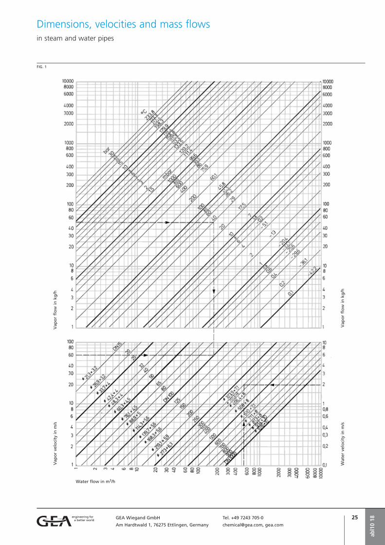
Dimensions, velocities and mass flows in steam and water pipes
abl1
0 18
Vap
or
flo
w i
n k
g/h
Vap
or
velo
city
in
m/s
Vap
or
flo
w i
n k
g/h
Wat
er v
elo
city
in
m/s
Water flow in m3/h
FIG. 1

26 GEA Wiegand GmbH Tel. +49 7243 705-0
Am Hardtwald 1, 76275 Ettlingen, Germany [email protected], gea.com
VACUUM
OVERPRESSURE
Vapor flows in pipes ab
l10
18
The tables on this sheet show the vapor flows in kg/h in relation to pressure and pipe diameter, for the usual flow velocities. In the case of air the throughput is very roughly double.
Vapor flows in kg/h at velocity
Vapor flows in kg/h at velocity
Vapor flows in kg/h at velocity
Vapor flows in kg/h at velocity
abs. pressure Internal pipe diameterin mbar 32 40 50 70 80 100 125 150 200 250 300 350 400 500
0.1 0.02 0.04 0.05 0.11 0.14 0.22 0.34 0.49 0.87 1.4 2 2.7 3.5 5.4
0.2 0.04 0.07 0.1 0.2 0.26 0.41 0.64 0.93 1.6 2.6 -3.7 5 16.6 10
0.3 0.06 0.1 0.15 0.3 0.39 0.6 0.94 1.4 2.4 3.8 5.4 7.4 9.7 15
0.4 0.08 0.13 0.2 0.39 0.51 0.8 1.3 1.8 3.2 5 7.2 9.7 13 20
0.5 0.1 0.16 0.25 0.49 0.64 1 1.6 2.3 4 6.3 9 12 16 25
0.6 0.12 0.19 0.3 0.58 0.76 1.2 1.9 2.7 4.8 7.4 11 15 19 29
0.7 0.14 0.22 0.35 0.68 0.88 1.4 2.2 3.1 5.5 8.6 12 17 22 35
0.8 0.16 0.25 0.39 0.77 1 1.6 2.4 3.5 6.3 9.8 14 19 25 39
0.9 0.18 0.28 0.44 0.85 1.1 1.7 2.7 3.9 7 11 16 21 28 44
abs. pressure Internal pipe diameterin mbar 32 40 50 70 80 100 125 150 200 250 300 350 400 500
1 0.15 0.23 0.36 0.71 0.93 1.5 2.3 3.3 5.8 9.1 13 18 23 36
2 0.29 0.45 0.71 1.4 1.8 2.8 4.4 6.4 11 18 26 35 45 70
3 0.43 0.67 1 2 2.7 4.2 6.5 9.4 17 26 37 51 67 104
5 0.7 1.1 1.7 3.3 4.3 6.8 11 15 27 42 61 83 108 170
10 1.4 2.1 3.3 6.4 8.4 13 21 30 52 82 120 160 210 330
20 2.6 4 6.3 12 16 25 40 57 100 160 230 310 400 630
30 3.8 5.9 9.3 18 24 37 58 83 150 230 335 455 595 925
50 6.2 9.7 15 30 39 61 95 136 240 380 545 740 970 1515
75 9 14 22 43 56 88 137 200 350 550 790 1075 1405 2200
100 12 19 29 57 74 120 180 260 465 725 1040 1420 1850 2900
150 17 27 42 83 108 170 265 380 670 1060 1525 2075 2710 4230
200 23 35 55 109 140 220 345 500 885 1390 1990 2720 3520 5520
300 33 52 80 160 205 325 505 725 1290 2015 2900 3950 5160 8065400 44 68 106 210 270 425 690 955 1700 2670 3820 5200 6800 10600
abs. pressure Internal pipe diameterin mbar 32 40 50 70 80 100 125 150 200 250 300 350 400 500
500 35 55 86 170 220 345 540 780 1380 2160 3110 4240 5530 8650
600 42 66 105 200 265 415 645 930 1660 2590 3730 5070 6630 10400
700 49 77 120 235 310 480 750 1080 1920 3000 4310 5870 7670 12000
800 55 87 135 270 350 540 850 1220 2200 3400 4900 6600 8600 13600
900 61 95 150 290 380 600 930 1340 2380 3720 5360 7300 9530 14900
1000 70 110 160 330 435 680 1060 1500 2700 4250 6100 8300 10850 17000
Pressure Internal pipe diameterbar 20 25 32 40 50 70 80 100
1 38 60 98 153 240 470 615 960
1,5 47 74 121 189 296 580 755 1180
2 56 88 144 224 350 690 900 1400
2,5 65 101 166 259 405 795 1035 1620
3 74 115 188 294 460 900 1175 1840
4 90 141 232 360 565 1110 1450 2260
5 108 168 275 430 675 1320 1720 2700
6 124 194 320 500 775 1520 1990 3110
8 158 245 405 630 985 1935 2530 3950
10 192 300 490 765 1200 2350 3070 4790
12 225 350 575 900 1405 2750 3600 5620
15 275 430 700 1095 1710 3350 4380 6840
18 325 505 830 1290 2020 3960 5170 8080
20 355 550 905 1415 2210 4330 5660 8840
25 440 685 1120 1750 2740 5370 7010 10960

27GEA Wiegand GmbH Tel. +49 7243 705-0
Am Hardtwald 1, 76275 Ettlingen, Germany [email protected], gea.com
According to the Law of Continuity the fol-lowing shall apply:Ø = a · w · r (1)
Ø Mass flow
a Flow cross section
w Velocity
r Density of the flowing medium
p1 Pressure upstream of the nozzle
J1 Temperature upstream of the nozzle
c Specific heat capacity
j Coefficient of loss
The aforementioned equation is valid for any point in a nozzle, when the values for a, w and r, present at this point, are filled in.
The mass flow through a nozzle is deter-mined by the narrowest cross section of the nozzle.
With the diminishing cross section, the velocity w = 0 at the condition p1, J1 and r1 increases up the narrowest point of the nozzle. At critical or over-critical pressure drops, sonic velocity is reached at this point. Supercritical pressure drops followed by a diverging nozzle section (Laval nozzle) further increase the velocity.This critical pressure ratio is only dependent on the ratio of the specific heat capacities
and therewith constant for a particular gas:
The mass flow through a nozzle whose inlet pressure is constant upstream of the noz-zle, first increases with decreasing pressure downstream of the nozzle; the mass flow reaches its maximum at the critical pressure ratio and from then on remains constant.
For the calculation of the mass flows, two cases have to be considered:a) critical or supercritical pressure drops,b) subcritical pressure drops.
In most cases steam jet pumps are operated with nozzles operating at supercritical pressure drops. Only these nozzles will be considered in the following.Assuming an adiabatic expansion in the noz-zle, the mass flow is calculated as follows:
with
Thus, the mass flow only depends on the condition of the gas upstream of the noz-zle and its properties. The coefficients of loss of well finished nozzles are today so well known that for the purpose of calculat-ing the mass flow, the motive nozzles of jet pumps supply far more accurate values than any other form of throughput measuring.Therefore, motive nozzles can be directly used for the exact calculation of the motive medium mass flow rate.
For water vapor the following values are usedk = 1.3
This value is valid for superheated steam and for saturated steam as in spite of the expansion leading in the wet steam range, the steam remains dry due to delayed con-densation.
At k = 1.3 the critical pressure drop results with p1/pcrit. = 1.83 and ycrit. = 0.473.
The diagram on page 26 was prepared with these values and with the equation for the mass flow (1).Two examples are shown:
1. 96 kg/h steam pass through the nozzle at saturated steam of p1 = 4 bar absolute pressure and a nozzle diameter of 7.5 mm.
2. Approx. 53 kg/h steam pass through a nozzle with a diameter of 4 mm at super-heated steam (JD = 300 ç) with an abso-lute pressure of p1 = 9 bar.
Depending on the condition of the steam JS either the curve for saturated steam or the corresponding temperature curve for super-heated steam JD should be used.
Literature:
1) VDMA information sheet no. 24294, sheet 1 and 2
2) DIN sheet 28430
Mass flow of gases and vapors through nozzles
abl1
1 18

28 GEA Wiegand GmbH Tel. +49 7243 705-0
Am Hardtwald 1, 76275 Ettlingen, Germany [email protected], gea.com
Water vapor flow through motive nozzles at critical pressure ratioab
l11
18
Wat
er v
apo
r fl
ow
Ø1
in k
g/h
Wat
er v
apo
r p
ress
ure
p1
in b
ar a
bs.
in
fro
nt
of
the
no
zzle
JS = Saturated steam temperature
JD = Steam temperature
d1 = Motive nozzle diameter
FIG. 1
Water vapor flow through motive nozzles at critical pressure ratio
29GEA Wiegand GmbH Tel. +49 7243 705-0
Am Hardtwald 1, 76275 Ettlingen, Germany [email protected], gea.com
In order to design a steam jet vacuum pump the suction flow must first be established.The latter is determined by operating condi-tions that are to be indicated by the custom-er. Normally the suction flow is made up of various components, partly of condensable vapors, and partly of inert gases.For more detailed indications for determin-ing the suction flows please refer to “Plan-ning a steam jet vacuum pumps”, o | gdp3.
The suction flow of a steam jet vacuum pump depends on the suction pressure, the molecular mass and the temperature of the suction medium being conveyed. The high-er the molecular mass, the more a jet pump can take in; the higher the temperature, the lower the suction flow and vice versa.
Capacity testing and acceptance tests on completed steam jet pumps should take place under exactly established and repro-ducible working conditions. Only in rare cases the original conditions regarding molecular mass and temperature can be reproduced. In general, only air or water vapor are at disposal as suction medium for such tests, particularly when they take place in the manufacturing works. For this reason, such measurements are taken with equivalent suction flows, i.e. suction flows which are converted to the air or water vapor equivalent.
The calculation of these equivalent suction flows is made in accordance with interna-tionally recognized rules which are estab-lished in VDMA work sheet no. 24294 (1), in the DIN sheet 28430 (2) or in the HEI Stan-dards (3). With correct application, these documents give same values.This work sheet gives a simplified version of the relatively complicated methods of cal-culation described in the above-mentioned literature.
The calculation for equivalent suction flows is based on the equation:
Where:
Ø01 Actual suction flow in kg/h
Ø02 Equivalent suction flow in kg/h
(air or water vapor)
f1 Suction flow factor
f2 Equivalent suction flow factor
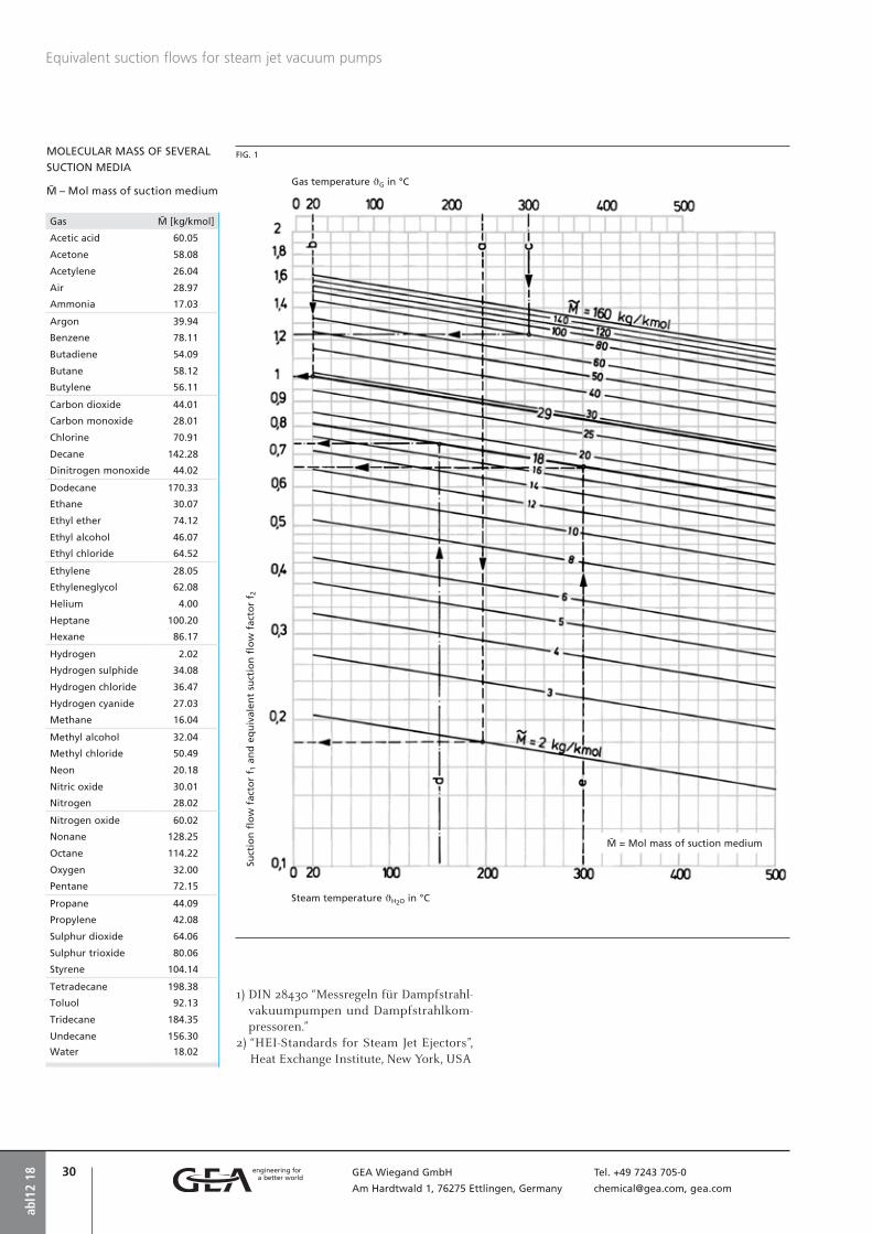
f1 and f2 can be found in diagram fig. 1.
In the application of this diagram on page 28 it is to be noted that the temperatures on the bottom scale are only valid for water vapor, whereas for all other gases and vapors the temperature should be read from the top scale.
EXAMPLE 1
OPERATING AND DESIGN DATA:
From fig. 1 the graph line “a” gives a suction flow factor f1 = 0.179.For the acceptance test in the manufacturing workshop, the actual suction medium (hydro-gen) is substituted with air, with the molec-ular mass and JG = 20 °C.From fig. 1 graph line “b” gives the equiva-lent flow factorThereby the equivalent air suction flow is
calculated:
EXAMPLE 2
OPERATING AND DESIGN DATA:
From fig. 1 the graph line “c” gives a suction flow factor f1 = 1.22.The test should be conducted using water vapor (mol mass ø02 = 18 kg/kmol) JH20 = 150 °C.From fig. 1 graph line “d” gives the equiva-lent flow factor f2 = 0.73.Thereby the equivalent steam suction flow
is calculated:
EXAMPLE 3
OPERATING AND DESIGN DATA:
Mixed suction flow
100 kg/h Water vapor
+ 200 kg/h Hydrocarbon vapor
ø = 100 kg/kmol
+ 22 kg/h Inert gases ø = 29 kg/kmol
= 322 kg/h
Temperature of the mixture JG = 300 °C
For mixtures of water vapor, other vapor and inert gases, the water vapor portion on the one hand and the vapor/inert gas por-tion on the other hand have to be converted separately.It is therefore necessary to first determine the mean mol mass for the vapor/inert gas portion (without water vapor):
The conversion shall be done in an equiva-lent water vapor flow of JH20 = 150 °C:For the water vapor portion you will find in diagram fig. 1
at JH20 = 300 °C and ø = 18 kg/kmol
f1 = 0.65 (continuous line “e”)
at JH20 = 150 °C and ø = 18 kg/kmol
f2 = 0.73 (continuous line “d”)
Hence results:
For the vapor/inert gas portion you will find in diagram fig. 1
at JG = 300 °C and ø = 80 kg/kmol
f1 = 1.22 (continuous line “c”)
and at JH20 = 150 °C and ø = 18 kg/kmol
f2 = 0.73 (continuous line “d”)
Hence results:
Thus, the total equivalent water vapor suction flow results with
Equivalent suction flows for steam jet vacuum pumps
abl1
2 18
30 GEA Wiegand GmbH Tel. +49 7243 705-0
Am Hardtwald 1, 76275 Ettlingen, Germany [email protected], gea.com
FIG. 1
Equivalent suction flows for steam jet vacuum pumps
abl1
2 18
Gas temperature JG in °C
Steam temperature JH2O in °C
Suct
ion
flo
w f
acto
r f 1
an
d e
qu
ival
ent
suct
ion
flo
w f
acto
r f 2
ø = Mol mass of suction medium
MOLECULAR MASS OF SEVERAL
SUCTION MEDIA
ø – Mol mass of suction medium
1) DIN 28430 “Messregeln für Dampfstrahl-vakuumpumpen und Dampfstrahlkom-pressoren.”
2) “HEI-Standards for Steam Jet Ejectors”, Heat Exchange Institute, New York, USA
Gas ø [kg/kmol]
Acetic acid 60.05
Acetone 58.08
Acetylene 26.04
Air 28.97
Ammonia 17.03
Argon 39.94
Benzene 78.11
Butadiene 54.09
Butane 58.12
Butylene 56.11
Carbon dioxide 44.01
Carbon monoxide 28.01
Chlorine 70.91
Decane 142.28
Dinitrogen monoxide 44.02
Dodecane 170.33
Ethane 30.07
Ethyl ether 74.12
Ethyl alcohol 46.07
Ethyl chloride 64.52
Ethylene 28.05
Ethyleneglycol 62.08
Helium 4.00
Heptane 100.20
Hexane 86.17
Hydrogen 2.02
Hydrogen sulphide 34.08
Hydrogen chloride 36.47
Hydrogen cyanide 27.03
Methane 16.04
Methyl alcohol 32.04
Methyl chloride 50.49
Neon 20.18
Nitric oxide 30.01
Nitrogen 28.02
Nitrogen oxide 60.02
Nonane 128.25
Octane 114.22
Oxygen 32.00
Pentane 72.15
Propane 44.09
Propylene 42.08
Sulphur dioxide 64.06
Sulphur trioxide 80.06
Styrene 104.14
Tetradecane 198.38
Toluol 92.13
Tridecane 184.35
Undecane 156.30
Water 18.02
31GEA Wiegand GmbH Tel. +49 7243 705-0
Am Hardtwald 1, 76275 Ettlingen, Germany [email protected], gea.com
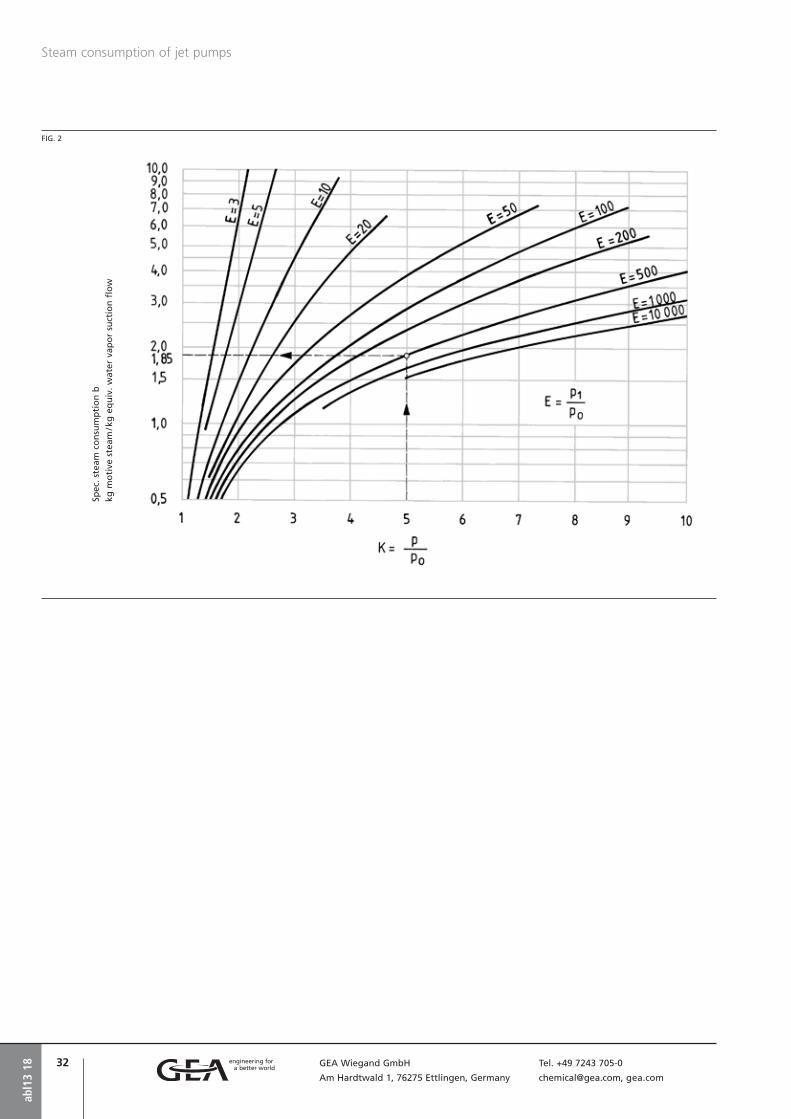
The steam consumption of a steam jet pump depends on the compression ratio K, the expansion ratio E, and the composition, mean molecular mass and temperature of the suction flow. (There are, however, some other influences which within the scope of this catalog sheet cannot be considered.)Since the steam consumption diagram fig. 2 applies for the removal of water vapor at J = 150 °C, the operating/design suction flowmust first be converted into an equivalentwater vapor suction flow at 150 °C (Ø0WE)according to DIN 28430.
The expansion ratio
and the compression ratio
are calculated on the basis of this.
The steam consumption considerably de-pends on both factors:The higher E, the less motive steam is required; but the higher K the more motive steam is required.In fig. 2 you find the specific motive steam consumption for K and E:
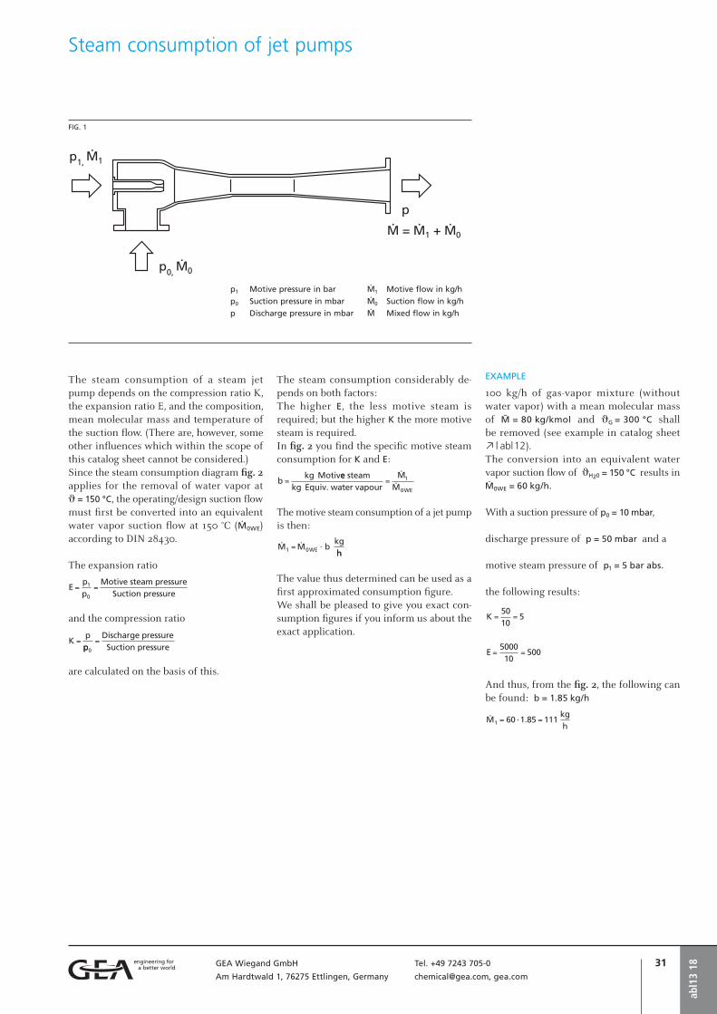
The motive steam consumption of a jet pump is then:
The value thus determined can be used as a first approximated consumption figure.We shall be pleased to give you exact con-sumption figures if you inform us about the exact application.
EXAMPLE
100 kg/h of gas-vapor mixture (without water vapor) with a mean molecular mass of ø = 80 kg/kmol and JG = 300 °C shall be removed (see example in catalog sheet o | abl12).The conversion into an equivalent water vapor suction flow of JH20 = 150 °C results in Ø0WE = 60 kg/h.
With a suction pressure of p0 = 10 mbar,
discharge pressure of p = 50 mbar and a
motive steam pressure of p1 = 5 bar abs.
the following results:
And thus, from the fig. 2, the following can be found: b = 1.85 kg/h
Steam consumption of jet pumps
abl1
3 18
FIG. 1
p1 Motive pressure in bar
p0 Suction pressure in mbar
p Discharge pressure in mbar
Ø1 Motive flow in kg/h
Ø0 Suction flow in kg/h
Ø Mixed flow in kg/h
32 GEA Wiegand GmbH Tel. +49 7243 705-0
Am Hardtwald 1, 76275 Ettlingen, Germany [email protected], gea.com
abl1
3 18
Steam consumption of jet pumps
FIG. 2
Spec
. st
eam
co
nsu
mp
tio
n b
kg m
oti
ve s
team
/ kg
eq
uiv
. w
ater
vap
or
suct
ion
flo
w
Grundlagen und Arbeitsblätter
• Liquid jet vacuum pumps, general information
• Liquid jet vacuum pumps with threaded connections
• Liquid jet vacuum pumps with fl anged connections
• Liquid jet vacuum pumps of PTFE
• Liquid jet gas compressors
• Liquid jet liquid pumps, general information
• Liquid jet liquid pumps of steel or stainless steel
• Standard liquid jet liquid pumps of PVC/PP
• Standard liquid jet liquid pumps of PTFE
• Liquid jet solids pumps
• Liquid jet mixers
• Liquid jet mixers for food applications/orbitally welded design
• Liquid jet ventilators
Grundlagen und ArbeitsblätterLiquid jet pumps

abl3
18

35GEA Wiegand GmbH Tel. +49 7243 705-0
Am Hardtwald 1, 76275 Ettlingen, Germany [email protected], gea.com
Liquid jet vacuum pumpsGeneral information
In most cases, liquid jet pumps are operated with water as motive medium. Depending on application and material, it is also possi-ble to use other liquids.The action of liquid jet pumps is based on the fact that the liquid jet coming out of the motive nozzle at high speed entrains air, gas, liquid or solid matters from the head of the jet pumps and compresses them to atmos-pheric pressure. For more detailed information on structure and mode of operation of jet pumps please refer to “General information on jet pumps”, o | abl1.
MODE OF OPERATION
Liquid jet vacuum pumps, when water is used as the motive medium, can be directly coupled to the water line. If, however, the water consumption has to be as economical as possible, the operating water may be circu l- ated. This is also the case when other liquids are used as the motive medium, instead of water.The temperature of the operating liquid may be kept low by the constant addition of a small quantity of fresh liquid. Higher
vacuum can be achieved by further cooling of the operating liquid. This is particularly expedient when the suction flow contains condensable components, e.g. solvents. In such a case the vacuum pump can be oper-ated by using the condensate as the motive medium.The lowest suction pressure which can be obtained with a suction capacity of zero (blind vacuum) corresponds to the vapor pressure of the motive liquid which depends on the temperature of the liquid. For the motive medium of water the rela-tionship between water temperature and lowest suction pressure is shown in fig. 2.
fvp
18
Stainless steel, with threaded connections
Stainless steel, with flanged connections
FIG. 1
Liquid jet vacuum pumps perform a perfect operation if the discharge pipe is below the liquid level or if a reducing piece is connect-ed to the liquid discharge (fig. 1).
A Service liquid
B Suction connection
C Fresh liquid
FIG. 2
Relation between water temperature and max. suction pressure
Abs. pressure in mbar
Wat
er t
emp
erat
ure
°C
PTFE, with flanged connections

36 GEA Wiegand GmbH Tel. +49 7243 705-0
Am Hardtwald 1, 76275 Ettlingen, Germany [email protected], gea.com
fvp
18
Questionnairefor liquid jet vacuum pumps fvp1, fvp2, fvp3
MATERIAL OF CONSTRUCTION . . . . . . . . . . . . . . . . . . . . . . . . . . . . . . . . . . . . . . . . . . . . . . . . .
CONNECTIONS:
Flanges
Thread
Others
Company . . . . . . . . . . . . . . . . . . . . . . . . . . . . .
attn. . . . . . . . . . . . . . . . . . . . . . . . . . . . . . . . .
Street/P.O. Box . . . . . . . . . . . . . . . . . . . . . . . . .
ZIP code/City . . . . . . . . . . . . . . . . . . . . . . . . . .
Country . . . . . . . . . . . . . . . . . . . . . . . . . . . . . .
YOUR ADDRESS Telephone . . . . . . . . . . . . . . . . . . . . . .
Telefax . . . . . . . . . . . . . . . . . . . . . . . . .
E-mail . . . . . . . . . . . . . . . . . . . . . . . . .
Motive medium . . . . . . . . . . . . . . . . . .
Motive flow . . . . . . . . . . . . . . . . . . . . . m³/h
Motive pressure . . . . . . . . . . . . . . . . . . bar abs.
1. MOTIVE SIDE Temperature . . . . . . . . . . . . . . . . . . . . . °C
Density . . . . . . . . . . . . . . . . . . . . . . . . kg/m³
Concentration . . . . . . . . . . . . . . . . . . . weight %
Steam pressure . . . . . . . . . . . . . . . . . . . bar abs.
Suction medium . . . . . . . . . . . . . . . . . .
Suction flow . . . . . . . . . . . . . . . . . . . . . kg/h
Suction pressure . . . . . . . . . . . . . . . . . . bar abs.
2. SUCTION SIDE Temperature . . . . . . . . . . . . . . . . . . . . . °C
Density . . . . . . . . . . . . . . . . . . . . . . . . kg/m³
Concentration . . . . . . . . . . . . . . . . . . . weight %
Required discharge pressure . . . . . . . . . . bar abs.
Mixed flow . . . . . . . . . . . . . . . . . . . . . . kg/h
3. OUTLET Concentration . . . . . . . . . . . . . . . . . . . weight %
FLANGES ACCORDING TO:
EN1092-1
ASME lbs
Others
4. FURTHER DATA
DESIGN CODE (if required):
AD-2000
ASME
Others
APPLICATION:
. . . . . . . . . . . . . . . . . . . . . . . . . . . . . .
. . . . . . . . . . . . . . . . . . . . . . . . . . . . . .
. . . . . . . . . . . . . . . . . . . . . . . . . . . . . .
DESIGN:
Temperature . . . . . . . . . . . . . . . . . . . . . °C Pressure . . . . . . . . . . . . . . . . . . . . . . . . bar g
FURTHER NOTES: . . . . . . . . . . . . . . . . . . . . . . . . . . . . . . . . . . . . . . . . . . . . . . . . . . . . . . . . . . .
. . . . . . . . . . . . . . . . . . . . . . . . . . . . . . . . . . . . . . . . . . . . . . . . . . . . . . . . . . . . . . . . . . . . . . .
. . . . . . . . . . . . . . . . . . . . . . . . . . . . . . . . . . . . . . . . . . . . . . . . . . . . . . . . . . . . . . . . . . . . . . .
Additional details, if required, are to be stated separately.
Your inquiry no. . . . . . . . . . . . . . . . . . .
Offer submitted until . . . . . . . . . . . . . .
Requested date of delivery . . . . . . . . . . .
Link to fillable PDF

37GEA Wiegand GmbH Tel. +49 7243 705-0
Am Hardtwald 1, 76275 Ettlingen, Germany [email protected], gea.com
Liquid jet vacuum pumps with threaded connections
APPLICATIONS
Liquid jet vacuum pumps with threaded connections are mainly used in chemical laboratories for the production of vacuum, for example in vacuum distillation or dry-ing.They are also used for evacuating syphon lines, suction lines of circulating pumps and condensers; for deaeration of pressure ves-sels and for producing negative pressure in Nutsch filters.
PERFORMANCE CHART FOR VACUUM PUMPS
Diagram fig. 3 gives the mass suction flow in kg/h of air in relation to the suction pres-sure at various operating water pressures for 4 pump sizes. The curves are based on an operating water temperature of 20 °C.The motive liquid consumption or the motive liquid flow (circulating water opera-tion) can be taken from diagram fig 4.
EXAMPLE
0.35 kg/h of air has to be continuously exhausted out of a plant. The suction pres-sure amounts to 100 mbar abs. A motive water pressure of 5 bar g is available. The motive water has a temperature of 20 °C.
PARAMETERS TO BE FOUND: Size of pump and motive water consumption.SOLUTION: From diagram fig. 3, for a suction pressure of 100 mbar and a motive water pressure of 5 bar g, pump size 2 with a mass suction flow of 0.38 kg/h is closest to the required suction volume.From diagram fig. 4, for a motive water pressure of 5 bar g and a suction pressure of 100 mbar a motive water consumption of 2.35 m³/h for the chosen size 2 can be found.
fvp1
18
FIG. 3
p1 = Motive water pressure
Mas
s su
ctio
n f
low
Ø0
in k
g/h
(ai
r)
FIG. 4
Mo
tive
wat
er c
on
sum
pti
on
(mo
tive
wat
er f
low
) å
1 in
m3 /
h
Size Suction pressure p0 in mbar abs. (for water at 20 °C)
N = Low pressure construction (1.5 – 2 bar)
H = High pressure construction (3 – 6 bar)
Pressure indications in bar = bar g
Size Motive water pressure p1 in bar
N = Low pressure construction (1.5 – 2 bar)
H = High pressure construction (3 – 6 bar)
Pressure indications in bar = bar g
p0 = Suction pressure in mbar abs.

38 GEA Wiegand GmbH Tel. +49 7243 705-0
Am Hardtwald 1, 76275 Ettlingen, Germany [email protected], gea.com
fvp1
18
Liquid jet vacuum pumps with threaded connections
PERFORMANCE CHART FOR PRE-EVACUATORS
EVACUATION TIME
Diagram fi g. 5 gives the time in minutes a liquid jet vacuum pump size 2 needs to evac-uate a vessel volume of 100 l to a defi ned suction pressure.The selection of other sizes is achieved by the following conversion formula:
EXAMPLE
A vessel of 400 l is to be evacuated to 400 mbar in 5 minutes. The water pressure is 3 bar.PARAMETERS TO BE FOUND: Pump sizeSOLUTION: From diagram fi g. 5, for 400 mbar and 3 bar, a time of 1.8 min/100 l is found. For the evacuation of a vessel volume of 400 l, a liquid jet vacuum pump size 2 requires 4 x 1.8 = 7.2 minutes. However,
as only 5 minutes are available the above formula is used to calculate the factor for the size of pump required:
According to the table factor 1.5 correspond-ing to pump size 3 is closest to the calculat-ed value. Pump size 3 is therefore selected.
The motive liquid consumption is in-fl uenced by the suction pressure p0. This is established by means of the curves in fi g. 4.
FIG. 5
Suct
ion
pre
ssu
re i
n m
bar
ab
s.
Specific evacuation time tspec. in min/100 l vessel volume for size 2
p1 = Motive water pressure
N = Low pressure construction (1.5 – 2 bar)
H = High pressure construction (3 – 6 bar)
Pressure indications in bar = bar g
F Factor for the selection of the pump size
tspec. Specific evacuation time in min/100 l
(from diagram fig. 5)
tevac. Expected evacuation time in minutes
V Volume of vessel to be evacuated in liter
Size 0 1 2 3
Factor F 0.44 0.68 1 1.5
Motive pressure has to be given with inquiry/order.For inquiries please use our questionnaire.
STANDARD CONSTRUCTIONS:
I Housing: steel, motive nozzle: stainless steelII Completely stainless steel
SPECIAL CONSTRUCTIONS: Hastelloy, Titanium, plastics (PVC, PP, PVDF, PTFE) etc.
CONNECTIONS, DIMENSIONS AND WEIGHTS
Size 0 1 2 3
Operating water connection A G 1/2 G 3/4 G 1 G 11/2
Suction connection B G 1/2 G 1/2 G 3/4 G 1
Pressure connection C G 1/2 G 1/2 G 3/4 G 1
Dimensions in mm a 240 260 310 405
b 65 70 80 105
c 175 190 230 300
d 35 40 45 50
Weight in kg 0.9 1.4 2.3 3.1
FIG. 6

39GEA Wiegand GmbH Tel. +49 7243 705-0
Am Hardtwald 1, 76275 Ettlingen, Germany [email protected], gea.com
Liquid jet vacuum pumps with flanged connections
APPLICATIONS
Liquid jet vacuum pumps with flanged con-nections are mainly used for the production of vacuum in laboratories and in pilot and production plants for example for vacuum distillation and vacuum drying.They are also used for evacuating syphon lines, suction lines of circulating pumps and condensers; for the deaeration of pressure vessels and for producing negative pressure in a Nutsch filter, etc.
PERFORMANCE CHART FOR
VACUUM PUMPS
Diagram fig. 7 gives the mass suction flow in kg/h of air in relation to the suction pres-sure at various operating water pressures for 8 pump sizes.The curves are based on an operating water temperature of 20 °C.The motive liquid consumption or the motive liquid flow (circulating water opera-tion) can be taken from diagram fig. 8.
EXAMPLE
6 kg/h of air has to be continuously exhaust-ed out of a plant.The suction pressure amounts to 100 mbar abs. A motive liquid pressure of 5 bar g is available. The motive water has a tempera-ture of 20 °C.PARAMETERS TO BE FOUND: Size of pump and motive water consumption. SOLUTION: From diagram fig. 7, for a suction pressure of 100 mbar and a motive water pressure of 5 bar g, pump size 7 with a mass suction flow of 6.8 kg/h is closest to the required suction volume.From diagram fig. 8, for a motive water pressure of 5 bar g and a suction pressure of 100 mbar a motive water consumption of 23.5 m³/h for the chosen size 7 can be found.
fvp2
18
FIG. 7
p1 = Motive water pressure
Mas
s su
ctio
n f
low
Ø0
in k
g/h
(ai
r)
Size Suction pressure p0 in mbar abs. (for water at 20 °C)
N = Low pressure construction (1.5 – 2 bar)
H = High pressure construction (3 – 6 bar)
Pressure indications in bar = bar g
FIG. 8
Mo
tive
wat
er c
on
sum
pti
on
(mo
tive
wat
er f
low
) å
1 in
m3 /
h
Size Motive water pressure p1 in bar
N = Low pressure construction (1.5 – 2 bar)
H = High pressure construction (3 – 6 bar)
Pressure indications in bar = bar g
p0 = Suction pressure in mbar abs.

40 GEA Wiegand GmbH Tel. +49 7243 705-0
Am Hardtwald 1, 76275 Ettlingen, Germany [email protected], gea.com
Liquid jet vacuum pumps with fl anged connections
PERFORMANCE CHART FOR PRE-EVACUATORS
EVACUATION TIME
Diagram fi g. 9 gives the time in minutes a liquid jet vacuum pump size 4 needs to evac-uate a vessel volume of 1 m³ to a defi ned suction pressure.The selection of other sizes is achieved by the following conversion formula:
EXAMPLE
A vessel of 3 m³ is to be evacuated to 400 mbar in 10 minutes. The water pressure is 3 bar.PARAMETERS TO BE FOUND: Size of the pumpSOLUTION: From diagram fi g. 9, for 400 mbar and 3 bar, a time of 8 min/m³ is found. For the evacuation of a vessel volume of 3 m³,
a liquid jet vacuum pump size 4 requires 3 x 8 = 24 minutes. However, as only 10 min-utes are available the above formula is used to calculate the factor for the size of pump required:
According to the table factor 2.5 correspond-ing to pump size 6 is closest to the calculat-ed value. Pump size 6 is therefore selected.
The motive liquid consumption is influ-enced by the suction pressure p0. This is established by means of the curves in fi g. 8.
fvp2
18
F Factor for the selection of the pump size
tspec. Specific evacuation time in min/m³
(from diagram fig. 9)
tevac. Expected evacuation time in minutes
V Volume of vessel to be evacuated in m³
Size 1 2 3 4 5 6 7 8
Factor F 0.28 0.40 0.63 1 1.6 2.5 4 6.3
Motive pressure has to be given with inquiry/order.For inquiries please use our questionnaire.
STANDARD CONSTRUCTIONS:
I Housing: steel, motive nozzle: stainless steelII Completely stainless steelFlanges according to EN1092-1
SPECIAL CONSTRUCTIONS: Hastelloy, Titanium, plastics (PVC, PP, PVDF, PTFE) etc.
CONNECTIONS, DIMENSIONS AND WEIGHTS
FIG. 10
Size 1 2 3 4 5 6 7 8
Operating water connection A 25 25 32 40 50 65 65 80
Suction connection B 20 20 25 32 40 40 50 65
Pressure connection C 15 20 25 32 40 50 65 80
Dimensions in mm a 207 267 347 407 478 608 778 963
b 60 60 65 70 80 80 80 115
c 147 207 282 337 398 528 698 848
d 85 85 100 115 125 125 135 135
Weight in kg 8 10 13 18 26 35 55 65
FIG. 9
Suct
ion
pre
ssu
re i
n m
bar
ab
s.
Specific evacuation time tspec. in min/m3 vessel volume for size 4
p1 = Motive water pressure
N = Low pressure construction (1.5 – 2 bar)
H = High pressure construction (3 – 6 bar)
Pressure indications in bar = bar g
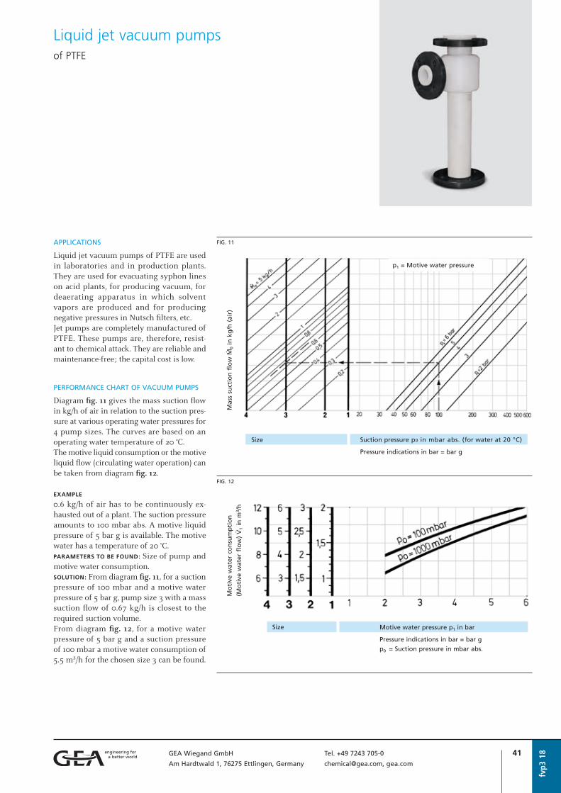
41GEA Wiegand GmbH Tel. +49 7243 705-0
Am Hardtwald 1, 76275 Ettlingen, Germany [email protected], gea.com
fvp3
18
Liquid jet vacuum pumps of PTFE
APPLICATIONS
Liquid jet vacuum pumps of PTFE are used in laboratories and in production plants. They are used for evacuating syphon lines on acid plants, for producing vacuum, for deaerating apparatus in which solvent vapors are produced and for producing negative pressures in Nutsch filters, etc.Jet pumps are completely manufactured of PTFE. These pumps are, therefore, resist-ant to chemical attack. They are reliable and maintenance-free; the capital cost is low.
PERFORMANCE CHART OF VACUUM PUMPS
Diagram fig. 11 gives the mass suction flow in kg/h of air in relation to the suction pres-sure at various operating water pressures for 4 pump sizes. The curves are based on an operating water temperature of 20 °C.The motive liquid consumption or the motive liquid flow (circulating water operation) can be taken from diagram fig. 12.
EXAMPLE
0.6 kg/h of air has to be continuously ex- hausted out of a plant. The suction pressure amounts to 100 mbar abs. A motive liquid pressure of 5 bar g is available. The motive water has a temperature of 20 °C. PARAMETERS TO BE FOUND: Size of pump and motive water consumption. SOLUTION: From diagram fig. 11, for a suction pressure of 100 mbar and a motive water pressure of 5 bar g, pump size 3 with a mass suction flow of 0.67 kg/h is closest to the required suction volume. From diagram fig. 12, for a motive water pressure of 5 bar g and a suction pressure of 100 mbar a motive water consumption of 5.5 m³/h for the chosen size 3 can be found.
Motive pressure has to be given with inquiry/order.For inquiries please use our questionnaire.
FIG. 11
p1 = Motive water pressure
Mas
s su
ctio
n f
low
Ø0
in k
g/h
(ai
r)
Size Suction pressure p0 in mbar abs. (for water at 20 °C)
Pressure indications in bar = bar g
FIG. 12
Mo
tive
wat
er c
on
sum
pti
on
(Mo
tive
wat
er f
low
) å
1 in
m3 /
h
Size Motive water pressure p1 in bar
Pressure indications in bar = bar g
p0 = Suction pressure in mbar abs.

42 GEA Wiegand GmbH Tel. +49 7243 705-0
Am Hardtwald 1, 76275 Ettlingen, Germany [email protected], gea.com
PERFORMANCE CHART FOR PRE-EVACUATORS
EVACUATION TIME
Diagram fi g. 13 gives the time in minutes a liquid jet vacuum pump size 3 needs to evac-uate a vessel volume of 1 m³ to a defi ned suction pressure.The selection of other sizes is achieved by the following conversion formula:
EXAMPLE
A vessel of 2 m³ is to be evacuated to 400 mbar in 15 minutes. The water pressure is 3 bar.PARAMETERS TO BE FOUND: Size of the pumpSOLUTION: From diagram fi g. 13, for 400 mbar and 3 bar, a time of 12 min/m³ is found. For the evacuation of a vessel volume of 2 m³, a liquid jet vacuum pump size 3 requires
2 x 12 = 24 minutes. However, as only 15 minutes are available the above formula is used to calculate the factor for the larger size of pump required:
According to the table factor 2 correspond-ing to pump size 4 is closest to the calculat-ed value. Pump size 4 is therefore selected.
The motive liquid consumption is influ-enced by the suction pressure p0. This is established by means of the curves in fi g. 12.
Liquid jet vacuum pumps of PTFE
fvp3
18
Größe 1 2 3 4
Operating water connection A 32 32 40 50
Suction connection B 25 25 25 32
Pressure connection C 32 32 50 65
Dimensions in mm a 290 290 390 500
b 90 90 95 105
c 200 200 295 395
d 90 90 100 110
Weight in kg 3 3 5 7
STANDARD CONSTRUCTION:
PTFE, loose fl ange made in GF-UPConnections according to EN1092-1
METAL AND SPECIAL CONSTRUCTIONS:
Please see “Liquid jet vacuum pumps with threaded connections”, o | fvp1, and“Liquid jet vacuum pumps with fl anged connections”, o | fvp2.
CONNECTIONS, DIMENSIONS AND WEIGHTS
FIG. 14
F Factor for the selection of the pump size
tspec. Specific evacuation time in min/m³
(from diagram fig. 13)
tevac. Expected evacuation time in minutes
V Volume of vessel to be evacuated in m³
Size 1 2 3 4
Factor F 0.33 0.5 1 2
FIG. 13
Suct
ion
pre
ssu
re i
n m
bar
ab
s.
Specific evacuation time tspec. in min/m3 vessel volume for size 3
Pressure indications in bar = bar g
p1 = Motive water pressure
For inquiries please use our questionnaire.

43GEA Wiegand GmbH Tel. +49 7243 705-0
Am Hardtwald 1, 76275 Ettlingen, Germany [email protected], gea.com
APPLICATION AND MODE OF OPERATION
Liquid jet gas compressors are jet pumps for the conveyance and compression of gases at simultaneous mixing with the motive liquid. Their operation is based on the liquid jet emerging from the motive nozzle hitting and entraining the surrounding gases and compressing them to a higher pressure (see also “General information on jet pumps”, o | abl1).
PERFORMANCE CHART
Fig. 1 shows the relation between the per-missible suction ration
of the pressure difference to be overcomeΔp = p–p0
and the effective motive liquid pressureΔp1 = p1–p0
The suction ratio j of sucked-in gas flow to the required motive liquid flow • increases with increasing motive liquid
pressure p1.• lowers with increasing compression Δp1.• is independent of type and density of the
gas to be conveyed.
EXAMPLE
for the selection of a liquid jet gas compres-sorGIVEN:
å0 = 13 m3/h of gas
p0 = –0.2 bar (= 0.8 bar abs.)
p1 = 3 bar
p = 0.7 bar
PARAMETERS TO BE FOUND:
Motive liquid flow å1 and size of the com-pressorSOLUTION:
Δp = p – p0 = 0.7 – (–0.2) = 0.9 bar
Δp1 = p1 – p0 = 3 – (–0.2) = 3.2 bar
From fig. 1 you will find for Δp = 0.9 bar and Δp1 = 3.2 bar:
This results in:
Liquid jet gas compressors
fgv1
18
FIG. 1
Pres
sure
dif
fere
nce
Δp
= p
–p0
in b
ar
Δp1 = p1–p0 = Effective motive liquid pressure
p1 = Motive liquid pressure in bar
p0 = Suction pressure in bar
p = Discharge pressure in bar
Dp = p – p0 = Total delivery pressure in bar
Dp1 = p1 – p0 = Effective motive liquid
pressure in bar
å1 = Motive liquid flow in m3/h
å0 = Gas suction flow in m3/h
å = Mixed flow in m3/h
(Pressure indications in bar = bar g)
Plastic construction, PVC, type G
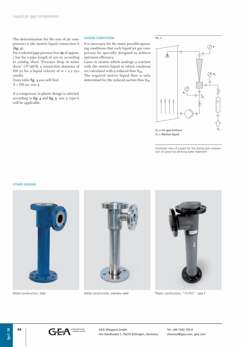
44 GEA Wiegand GmbH Tel. +49 7243 705-0
Am Hardtwald 1, 76275 Ettlingen, Germany [email protected], gea.com
DESIGN CONDITIONS
It is necessary for the many possible operat-ing conditions that each liquid jet gas com-pressor be specially designed to achieve optimum efficiency.Gases or steams which undergo a reaction with the motive liquid or which condense are calculated with a reduced flow åOR.The required motive liquid flow is only determined for the reduced suction flow åOR.
fgv1
18
Liquid jet gas compressors
Metal construction, steel Plastic construction, “75 PVC”, type FMetal construction, stainless steel
OTHER DESIGNS
FIG. 2
å0 = Air-gas-mixture
å1 = Motive liquid
Schematic view of a plant for the dosing and compres-sion of ozone for drinking water treatment
The determination for the size of jet com-pressors is the motive liquid connection A (fig. 3):For a selected pipe pressure loss Δp of approx. 1 bar for a pipe length of 100 m, according to catalog sheet “Pressure drop in water ducts” (o | abl9), a connection diameter ofDN 50 for a liquid velocity of w = 2.2 m/s results.From table fig. 3 you will findA = DN 50: size 4.
If a compressor in plastic design is selected, according to fig. 4 and fig. 5, size 5, type G will be applicable.

45GEA Wiegand GmbH Tel. +49 7243 705-0
Am Hardtwald 1, 76275 Ettlingen, Germany [email protected], gea.com
fgv1
18
Liquid jet gas compressors
STANDARD CONSTRUCTIONS:
I Housing: steel, motive nozzle: stainless steel, inlet guide vane: PVCII Housing: steel, inner surfaces lined with PFA,
motive/mixing nozzle: PVC, inlet guide vane: PVCIII Completely stainless steelFlanges according to EN1092-1
SPECIAL CONSTRUCTIONS: Hastelloy, Titanium, plastics (PP, PVDF, PTFE, PVC/GF-UP) etc.
For inquiries please use our questionnaire.
CONNECTIONS, DIMENSIONS AND WEIGHTSMETAL CONSTRUCTION
FIG. 3
Size 1 2 3 4 5 6 7 8
Liquid connection A 25 32 40 50 65 65 80 100
Suction connection B 20 25 32 40 40 50 65 80
Pressure connection C 32 40 50 65 65 80 100 125
Dimensions in mm a 270 350 410 480 480 530 730 950
b 60 65 70 80 80 80 115 150
c 210 285 340 400 400 450 615 800
d 85 100 115 125 125 135 135 165
Weight in kg 10 13 15 22 22 30 45 98
Size 1 2 3 4 5 6 7 8 9 10
Liquid connection A 20 25 32 40 50 65 80 100 125 150
Dimensions in mm dA 25 32 40 50 63
a1 38 41 43 47 55
Suction connection B 20 20 20 25 32 50 65 80 100 125
Dimensions in mm dB 25 25 25 32 40
b1 27 30 33 36 41
Pressure connection C 20 25 32 40 50 65 80 100 125 150
Dimensions in mm dC 25 32 40 50 63
c1 30 33 36 41 46
Dimensions in mm a 280 320 410 530 610 600 675 825 1050 1250
b 100 105 125 150 170 100 115 135 165 190
c 180 215 285 380 440 500 560 690 885 1060
d 115 115 120 140 160 125 146 175 215 248
Weight in kg 0.6 0.8 1.2 1.9 2.9 5.5 8.5 13 25 35
Type G G G G G F F F F F
CONNECTIONS, DIMENSIONS AND WEIGHTSPLASTIC CONSTRUCTION PVC
FIG. 4 FIG. 5
TYPE G: with screw connectionsTYPE F: Connections: loose fl ange made in GF-UPFlanges according to EN1092-1
For inquiries please use our questionnaire.
Type G Type F

46 GEA Wiegand GmbH Tel. +49 7243 705-0
Am Hardtwald 1, 76275 Ettlingen, Germany [email protected], gea.com
fgv1
18
Questionnairefor liquid jet gas compressors fgv1
MATERIAL OF CONSTRUCTION . . . . . . . . . . . . . . . . . . . . . . . . . . . . . . . . . . . . . . . . . . . . . . . . .
CONNECTIONS:
Flanges
Thread
Others
Company . . . . . . . . . . . . . . . . . . . . . . . . . . . . .
attn. . . . . . . . . . . . . . . . . . . . . . . . . . . . . . . . .
Street/P.O. Box . . . . . . . . . . . . . . . . . . . . . . . . .
ZIP code/City . . . . . . . . . . . . . . . . . . . . . . . . . .
Country . . . . . . . . . . . . . . . . . . . . . . . . . . . . . .
YOUR ADDRESS Telephone . . . . . . . . . . . . . . . . . . . . . .
Telefax . . . . . . . . . . . . . . . . . . . . . . . . .
E-mail . . . . . . . . . . . . . . . . . . . . . . . . .
Motive medium . . . . . . . . . . . . . . . . . .
Motive flow . . . . . . . . . . . . . . . . . . . . . m³/h
Motive pressure . . . . . . . . . . . . . . . . . . bar abs.
1. MOTIVE SIDE Temperature . . . . . . . . . . . . . . . . . . . . . °C
Density . . . . . . . . . . . . . . . . . . . . . . . . kg/m³
Concentration . . . . . . . . . . . . . . . . . . . weight %
Steam pressure . . . . . . . . . . . . . . . . . . . bar abs.
Suction medium . . . . . . . . . . . . . . . . . .
Suction flow . . . . . . . . . . . . . . . . . . . . . m³/h
Suction pressure . . . . . . . . . . . . . . . . . . bar abs.
2. SUCTION SIDE Temperature . . . . . . . . . . . . . . . . . . . . . °C
Density . . . . . . . . . . . . . . . . . . . . . . . . kg/m³
Concentration . . . . . . . . . . . . . . . . . . . weight %
Required discharge pressure . . . . . . . . . . bar abs.
Mixed flow . . . . . . . . . . . . . . . . . . . . . . kg/h
3. OUTLET Concentration . . . . . . . . . . . . . . . . . . . weight %
FLANGES ACCORDING TO:
EN1092-1
ASME lbs
Others
4. FURTHER DATA
DESIGN CODE (if required):
AD-2000
ASME
Others
APPLICATION:
. . . . . . . . . . . . . . . . . . . . . . . . . . . . . .
. . . . . . . . . . . . . . . . . . . . . . . . . . . . . .
. . . . . . . . . . . . . . . . . . . . . . . . . . . . . .
DESIGN:
Temperature . . . . . . . . . . . . . . . . . . . . . °C Pressure . . . . . . . . . . . . . . . . . . . . . . . . bar g
FURTHER NOTES: . . . . . . . . . . . . . . . . . . . . . . . . . . . . . . . . . . . . . . . . . . . . . . . . . . . . . . . . . . .
. . . . . . . . . . . . . . . . . . . . . . . . . . . . . . . . . . . . . . . . . . . . . . . . . . . . . . . . . . . . . . . . . . . . . . .
. . . . . . . . . . . . . . . . . . . . . . . . . . . . . . . . . . . . . . . . . . . . . . . . . . . . . . . . . . . . . . . . . . . . . . .
Additional details, if required, are to be stated separately.
Your inquiry no. . . . . . . . . . . . . . . . . . .
Offer submitted until . . . . . . . . . . . . . .
Requested date of delivery . . . . . . . . . . .
Link to fillable PDF

47GEA Wiegand GmbH Tel. +49 7243 705-0
Am Hardtwald 1, 76275 Ettlingen, Germany [email protected], gea.com
wp
18
Stainless steel
Liquid jet liquid pumpsGeneral information
CONSTRUCTION AND MODE OF OPERATION
Liquid jet liquid pumps are jet pumps which suck in a liquid Ø0 by means of a motive liquid jet Ø1, mix the motive and suction flows and convey the mixed flow Ø (fig. 1).As with all jet pumps the motive liquid has the highest pressure p1, the suction flow the lowest pressure p0, and the pressure of the mixed flow p lies between the motive pres-sure and suction pressure p1 > p > p0 (see also “General information on jet pumps”, o | abl1).In order to convey the mixture, the total conveying pressure Δp must be overcome. This is determined by the geodetic height, pipeline resistance and the resistance of installed parts, such as shut-off valves or control valves etc. (see “Pressure loss in water pipelines”, o | abl9).
APPLICATIONS
Liquid jet liquid pumps are used for convey-ing and mixing liquids such as water, acids or lyes in water and waste water treatment plants.An important range of application is for the dilution of acids or lyes to a definite final concentration such as is required in water treatment plants.The ion exchangers at times have to be regenerated with acid (cation exchanger) or caustic (anion exchanger).
The liquid jet liquid pumps suck in the concentrated acid or lye and convey it into the exchangers at the respectively required mixing ratio.
FIG. 1
PVC, construction KT, glued, form M
PVC, construction K, screwed, form M
FIG. 2
Schematic view of a demineralization plant
1, 2 Jet pumps
3 Anion exchanger
4 CO2 stripper
5 Cation exchanger
A1 Water
A2 Water
B1 HCl
B2 NaOH

48 GEA Wiegand GmbH Tel. +49 7243 705-0
Am Hardtwald 1, 76275 Ettlingen, Germany [email protected], gea.com
The size of a liquid jet liquid pump is prin-cipally determined by the mixed flow Ø in kg/h.This can be found by the calculation as fol-lows:
Ø Mixed flow in kg/h
Ø1 Suction flow in kg/h
μ Spec. liquid consumption in kg motive
liquid / kg suction liquid
The motive liquid consumption is calculat-ed as follows:
Fig. 3 shows the relation between the pres-sure ratio d, the specific liquid consumption μ and the density ratio r0/r1.
The specific liquid consumption μ in kg motive liquid/kg suction liquid is greater the higher the pressure ratio d and the smaller the density ratio r0/r1;
and is smaller the higher the effective motive liquid pressure, that means the higher the difference between motive pres-sure and suction pressure p1-p0 and the greater the density ratio r0/r1.
EXAMPLE
GIVEN:
Suction flow Ø0 = 1000 kg/h effluent
Suction liquid over pressure
p0 = –0.2 bar = 2 m WC suction height
Motive liquid overpressure p1 = 4 bar
Discharge pressure p = 1 bar g
PARAMETERS TO BE FOUND: Required motive liquid flow Ø1 and pump sizeSOLUTION:
Fig. 3 gives for a density ratio r0/r1 = 1.0 a specific liquid consumption μ = 1.37.
DETERMINING THE PUMP SIZE:
fig. 4 gives pump size 5 (max. mixed flow 3500 kg/h)
CONSTRUCTION
Depending on the application, 3 types of liquid jet liquid pumps are available.
Liquid jet liquid pumps, general information
wp
18
FIG. 3
r0/r
1 = Density ratio of the liquids
PERFORMANCE CHART
= Specific liquid consumption
= Constant mixing ratio
p1 = Motive liquid pressure in bar g
p0 = Suction liquid pressure in bar g
suction (–), inlet (+)
p = Discharge pressure in bar
Δp = p – p0 = Total delivery pressure in bar g
Δp1 = p1 – p0 = Effective motive liquid
pressure in bar g
K = Concentration by weight-%
(Pressure indications in bar = bar g)
Motive flow Mixed flow
Ø1 Ø = Ø0 + Ø1
p1 p
K1 K
Suction flow
Ø0, p0, K0

49GEA Wiegand GmbH Tel. +49 7243 705-0
Am Hardtwald 1, 76275 Ettlingen, Germany [email protected], gea.com
wp
18
Questionnairefor liquid jet liquid pumps wp1, wp2, wp3
MATERIAL OF CONSTRUCTION . . . . . . . . . . . . . . . . . . . . . . . . . . . . . . . . . . . . . . . . . . . . . . . . .
CONNECTIONS:
Flanges
Thread
Others
Company . . . . . . . . . . . . . . . . . . . . . . . . . . . . .
attn. . . . . . . . . . . . . . . . . . . . . . . . . . . . . . . . .
Street/P.O. Box . . . . . . . . . . . . . . . . . . . . . . . . .
ZIP code/City . . . . . . . . . . . . . . . . . . . . . . . . . .
Country . . . . . . . . . . . . . . . . . . . . . . . . . . . . . .
YOUR ADDRESS Telephone . . . . . . . . . . . . . . . . . . . . . .
Telefax . . . . . . . . . . . . . . . . . . . . . . . . .
E-mail . . . . . . . . . . . . . . . . . . . . . . . . .
Motive medium . . . . . . . . . . . . . . . . . .
Motive flow . . . . . . . . . . . . . . . . . . . . . m³/h
Motive pressure . . . . . . . . . . . . . . . . . . bar abs.
1. MOTIVE SIDE Temperature . . . . . . . . . . . . . . . . . . . . . °C
Density . . . . . . . . . . . . . . . . . . . . . . . . kg/m³
Concentration . . . . . . . . . . . . . . . . . . . weight %
Steam pressure . . . . . . . . . . . . . . . . . . . bar abs.
Suction medium . . . . . . . . . . . . . . . . . .
Suction flow . . . . . . . . . . . . . . . . . . . . . kg/h
Suction pressure . . . . . . . . . . . . . . . . . . bar abs.
Temperature . . . . . . . . . . . . . . . . . . . . . °C
2. SUCTION SIDE Density . . . . . . . . . . . . . . . . . . . . . . . . kg/m³
Concentration . . . . . . . . . . . . . . . . . . . weight %
Dyn. viscosity . . . . . . . . . . . . . . . . . . . . mPas
Required discharge pressure . . . . . . . . . . bar abs.
Mixed flow . . . . . . . . . . . . . . . . . . . . . . kg/h
3. OUTLET Concentration . . . . . . . . . . . . . . . . . . . weight %
FLANGES ACCORDING TO:
EN1092-1
ASME lbs
Others
4. FURTHER DATA
DESIGN CODE (if required):
AD-2000
ASME
Others
APPLICATION:
. . . . . . . . . . . . . . . . . . . . . . . . . . . . . .
. . . . . . . . . . . . . . . . . . . . . . . . . . . . . .
. . . . . . . . . . . . . . . . . . . . . . . . . . . . . .
DESIGN:
Temperature . . . . . . . . . . . . . . . . . . . . . °C Pressure . . . . . . . . . . . . . . . . . . . . . . . . bar g
FURTHER NOTES: . . . . . . . . . . . . . . . . . . . . . . . . . . . . . . . . . . . . . . . . . . . . . . . . . . . . . . . . . . .
. . . . . . . . . . . . . . . . . . . . . . . . . . . . . . . . . . . . . . . . . . . . . . . . . . . . . . . . . . . . . . . . . . . . . . .
Additional details, if required, are to be stated separately.
Your inquiry no. . . . . . . . . . . . . . . . . . .
Offer submitted until . . . . . . . . . . . . . .
Requested date of delivery . . . . . . . . . . .
Link to fillable PDF
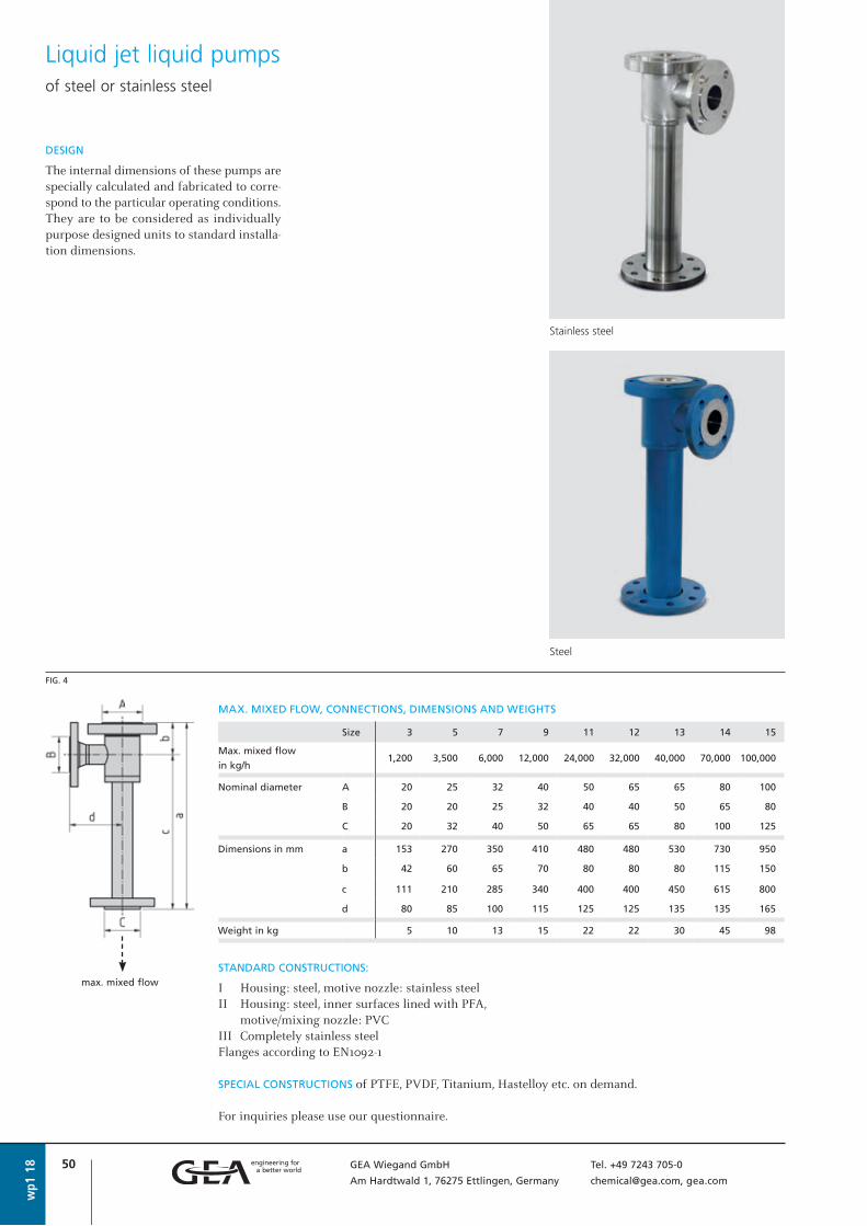
50 GEA Wiegand GmbH Tel. +49 7243 705-0
Am Hardtwald 1, 76275 Ettlingen, Germany [email protected], gea.com
wp1
18
Stainless steel
DESIGN
The internal dimensions of these pumps are specially calculated and fabricated to corre-spond to the particular operating conditions. They are to be considered as individually purpose designed units to standard installa-tion dimensions.
Liquid jet liquid pumps of steel or stainless steel
STANDARD CONSTRUCTIONS:
I Housing: steel, motive nozzle: stainless steelII Housing: steel, inner surfaces lined with PFA,
motive/mixing nozzle: PVCIII Completely stainless steelFlanges according to EN1092-1
SPECIAL CONSTRUCTIONS of PTFE, PVDF, Titanium, Hastelloy etc. on demand.
For inquiries please use our questionnaire.
MAX. MIXED FLOW, CONNECTIONS, DIMENSIONS AND WEIGHTS
FIG. 4
Size 3 5 7 9 11 12 13 14 15
Max. mixed flow
in kg/h1,200 3,500 6,000 12,000 24,000 32,000 40,000 70,000 100,000
Nominal diameter A 20 25 32 40 50 65 65 80 100
B 20 20 25 32 40 40 50 65 80
C 20 32 40 50 65 65 80 100 125
Dimensions in mm a 153 270 350 410 480 480 530 730 950
b 42 60 65 70 80 80 80 115 150
c 111 210 285 340 400 400 450 615 800
d 80 85 100 115 125 125 135 135 165
Weight in kg 5 10 13 15 22 22 30 45 98
Steel
max. mixed flow

51GEA Wiegand GmbH Tel. +49 7243 705-0
Am Hardtwald 1, 76275 Ettlingen, Germany [email protected], gea.com
PVC, construction KT, glued, form M
DESIGN AND PERFORMANCE CHART
EXAMPLE
Ø0 = 100 kg/h hydrochloric acid with K0 = 30 %
is to be diluted with the motive liquid water with a concentration of K1 = 0, to K = 4 %.Motive liquid pressure p1 = 2.5 bar g
Suction liquid pressure p0 = 0 bar g
Discharge pressure p = 0.8 bar g
SOLUTION: In the performance chart fig. 5 the horizontal from Ø0 = 100 kg/h intersects the dilution curve 30 % " 4 % giving on the abscissa Ø1 = 650 kg/h motive liquid flow.The intersection of the vertical Ø1 = 650 kg/h
with the “Type” curve 23-3 gives on the ordi-nate in the lower part of the chart en effective motive pressure of Δp1 = p1 – p0 = 2.2 bar.By multiplying this value with the d found on the dilution curve one can obtain the admissible total delivery pressure Δp = Δp1 · d = 2.2 · 0.55 = 1.21 bar.Thereby the achievable discharge pressure is p = 1.21 + p0 = 1.21 bar and the actually required motive liquid pressure isp1 = Δp1 + p0 = 2.2 bar.A liquid jet liquid pump size KT2 or K2, type 23-3 is required.
Standard liquid jet liquid pumps of PVC/PP
wp2
18
FIG. 5
Motive liquid flow (water) Ø1 in kg/h with the concentration K1 = 0
Suct
ion
liq
uid
flo
w Ø
0 in
kg
/h w
ith
th
e co
nce
ntr
atio
n K
0Ef
fect
ive
mo
tive
liq
uid
pre
ssu
re Δ
p1
= p
1–p
0 in
bar
Max. suction height: –2 m WC
Min. motive pressure: approx. 1.3 bar g
1 = Characteristic lines of usual
dilutions at K1 = 0
2 = Characteristic lines of the unit
P -Type = Pump-Type
= Specific liquid consumption
= Constant mixing ratiop1 = Motive liquid pressure in bar gp0 = Suction liquid pressure in bar g
suction (–), inlet (+)p = Discharge pressure in barΔp = p – p0 = Total delivery pressure in bar gΔp1 = p1 – p0 = Effective motive liquid pressure in bar g
K = Concentration in weight-%(Pressure indications in bar = bar g)
Motive flow Mixed flowØ1 Ø = Ø0 + Ø1
p1 pK1 K
Suction flowØ0, p0, K0

52 GEA Wiegand GmbH Tel. +49 7243 705-0
Am Hardtwald 1, 76275 Ettlingen, Germany [email protected], gea.com
wp2
18
Standard liquid jet liquid pumps of PVC/PP
Form M Form G Form F Form M Form G Form F
FIG. 6 FIG. 7
CONSTRUCTION KT CONSTRUCTION K
MAX. MIXED FLOW, CONNECTIONS, DIMENSIONS AND WEIGHTS
MAX. MIXED FLOW, CONNECTIONS, DIMENSIONS AND WEIGHTS
Size KT 1 KT 2 KT 3 KT 4 KT 5 KT 6 KT 7 KT 8
Type13-1
... 13-723-1
... 23-433-1
... 33-243-1
... 43-353-1
... 53-263-1
... 63-373-1
... 73-283-1
... 83-2
Nominal diameter A 15 20 25 32 40 50 65 80
B 15 20 25 32 40 50 65 80 C 15 20 25 32 40 50 65 80
Dimensions in mm dA 20 25 32 40 50 63 75 90 dB 20 25 32 40 50 63 75 90 dC 20 25 32 40 50 63 75 90
Dimensions in mm a 150 190 220 280 385 480 570 650 ( ) Dimensions for b 45 55 65 80 100 115 135 160
PP construction c 27 33 39 49 60 72 84 99 only (c) (28) (32) (38) (44) (51) (62) (75.5) (88)
Dimensions in mm a 208 254 290 362 481 598 680 782 ( ) Dimensions for (a) (212) (256) (290) (358) (473) (584) - -
PP construction b 74 87 100 121 148 174 190 226
only (b) (76) (88) (100) (119) (144) (167) - - c 100 115 130 150 180 210 215 245
Dimensions in mm a 156 196 226 286 391 486 576 660 ( ) Dimensions for (a) (160) (200) (230) (290) (395) (490) (580) (664)
PP construction b 48 58 68 83 103 118 138 165
only (b) (50) (60) (70) (85) (105) (120) (140) (167) c 90 100 100 115 125 145 165 185
Max. mixed flow in kg/h
500 1,200 2,000 3,500 6,000 12,000 25,000 50,000
Plastic construction KT, glued (PVC), welded (PP)
Plastic construction K, screwed
Form
MFo
rm G
Form
F
Size K 1 K 2 K 3 K 4 K 5 K 6 K 7 K 8
Typ13-1
... 13-723-1
... 23-433-1
... 33-243-1
... 43-353-1
... 53-263-1
... 63-373-1
... 73-283-1
... 83-2
Nominal diameter A 15 20 25 32 40 50 65 80
B 10 20 20 20 25 32 40 65 C 15 20 25 32 40 50 65 100
Dimensions in mm dA 20 25 32 40 50 63 75 90 dB 16 25 25 25 32 40 50 75 dC 20 25 32 40 50 63 75 110
Dimensions in mm a 155 190 200 260 385 460 520 800 b 65 70 70 85 100 110 145 210
c 30 40 40 45 60 60 80 97.5
Dimensions in mm a 213 254 270 342 481 578 650 951 ( ) Dimensions for (a) (217) (256) (270) (338) (473) (564) - -
PP construction b 94 102 105 126 148 169 210 284
only (b) (96) (103) (105) (124) (144) (162) - - c 100 115 115 120 140 160 180 200
Dimensions in mm a 161 196 206 266 391 466 526 810 ( ) Dimensions for (a) (165) (200) (210) (270) (395) (470) (530) (814)
PP construction b 68 73 73 88 103 113 148 215
only (b) (70) (75) (75) (90) (105) (115) (150) (217) c 90 100 100 100 120 140 160 180
Max. mixed flow in kg/h
500 1,200 2,000 3,500 6,000 12,000 25,000 50,000
Form
MFo
rm G
Form
F
STANDARD
Size, type, form and material must be given in all orders for standard liquid pumps, e.g. size KT1, type 13-3, form G, PP.Standard liquid jet liquid pumps of PVC/PP are available in the 6 above-mentioned constructions.
SEMI STANDARD
The inside dimensions of such pumps will be specially designed and fabricated accord-ing to the given operation con-ditions. These pumps are there-fore tailor-made constructions with standard structural dimen-sions.
SPECIAL CONSTRUCTIONS
Liquid pumps for dilutions, applications and materials other than shown in diagram fig. 5 are special constructions. Design, dimensions and connection dimensions on demand.
All connections for form M and G are provided as glued or weld-ed connections.
For inquiries please use our questionnaire.

53GEA Wiegand GmbH Tel. +49 7243 705-0
Am Hardtwald 1, 76275 Ettlingen, Germany [email protected], gea.com
wp3
18
DESIGN AND PERFORMANCE CHART
The jet pumps are completely manufactured of PTFE. The pumps are, therefore, resistant to chemical attack. They are reliable and maintenance-free; the capital cost is low.
Performance chart for a suction head of max. –0.5 m liquid column
Standard liquid jet liquid pumps of PTFE
Motive liquid flow (water) Ø1 in kg/h with the concentration K1 = 0
Suct
ion
liq
uid
flo
w Ø
0 in
kg
/h w
ith
th
e co
nce
ntr
atio
n K
0Ef
fect
ive
mo
tive
liq
uid
pre
ssu
re
Δp
1 =
p1–
p0
in b
ar
FIG. 8
Max. suction height: –0.5 m WC
1 = Characteristic lines
of usual dilutions at K1 = 0
2 = Characteristic lines of the unit
P -Type = Pump size
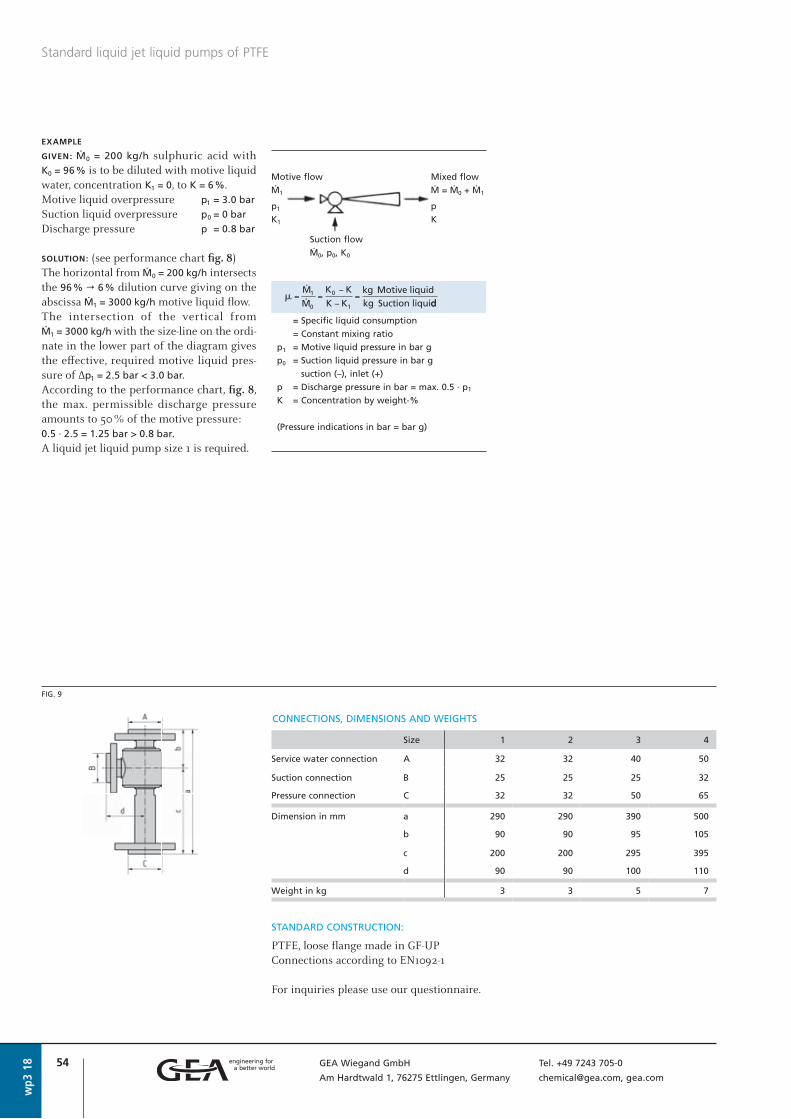
54 GEA Wiegand GmbH Tel. +49 7243 705-0
Am Hardtwald 1, 76275 Ettlingen, Germany [email protected], gea.com
wp3
18
EXAMPLE
GIVEN: Ø0 = 200 kg/h sulphuric acid with K0 = 96 % is to be diluted with motive liquid water, concentration K1 = 0, to K = 6 %.Motive liquid overpressure p1 = 3.0 bar
Suction liquid overpressure p0 = 0 bar
Discharge pressure p = 0.8 bar
SOLUTION: (see performance chart fi g. 8)The horizontal from Ø0 = 200 kg/h intersects the 96 % " 6 % dilution curve giving on the abscissa Ø1 = 3000 kg/h motive liquid fl ow.The intersection of the vertical from Ø1 = 3000 kg/h with the size-line on the ordi-nate in the lower part of the diagram gives the eff ective, required motive liquid pres-sure of Δp1 = 2.5 bar < 3.0 bar.According to the performance chart, fi g. 8, the max. permissible discharge pressure amounts to 50 % of the motive pressure: 0.5 · 2.5 = 1.25 bar > 0.8 bar.
A liquid jet liquid pump size 1 is required.
Standard liquid jet liquid pumps of PTFE
Size 1 2 3 4
Service water connection A 32 32 40 50
Suction connection B 25 25 25 32
Pressure connection C 32 32 50 65
Dimension in mm a 290 290 390 500
b 90 90 95 105
c 200 200 295 395
d 90 90 100 110
Weight in kg 3 3 5 7
STANDARD CONSTRUCTION:
PTFE, loose fl ange made in GF-UPConnections according to EN1092-1
For inquiries please use our questionnaire.
CONNECTIONS, DIMENSIONS AND WEIGHTS
FIG. 9
= Specific liquid consumption
= Constant mixing ratio
p1 = Motive liquid pressure in bar g
p0 = Suction liquid pressure in bar g
suction (–), inlet (+)
p = Discharge pressure in bar = max. 0.5 · p1
K = Concentration by weight-%
(Pressure indications in bar = bar g)
Motive flow Mixed flow
Ø1 Ø = Ø0 + Ø1
p1 p
K1 K
Suction flow
Ø0, p0, K0
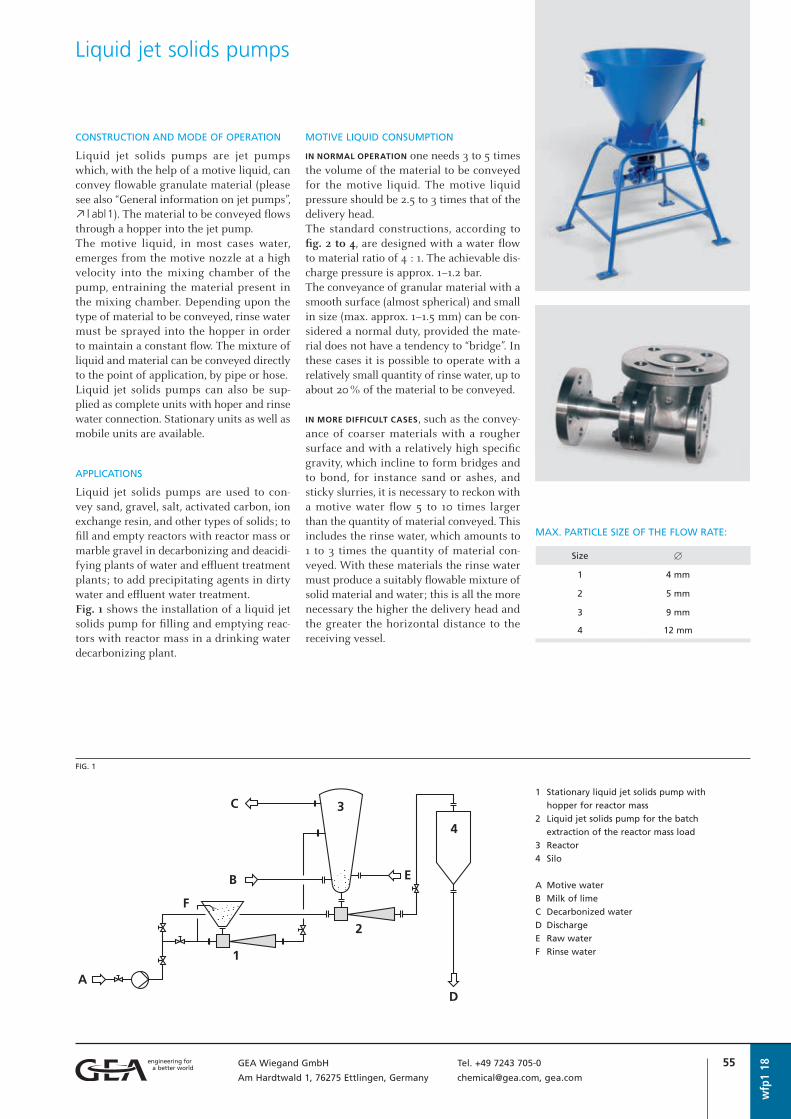
55GEA Wiegand GmbH Tel. +49 7243 705-0
Am Hardtwald 1, 76275 Ettlingen, Germany [email protected], gea.com
wfp
1 18
CONSTRUCTION AND MODE OF OPERATION
Liquid jet solids pumps are jet pumps which, with the help of a motive liquid, can convey flowable granulate material (please see also “General information on jet pumps”, o | abl1). The material to be conveyed flowsthrough a hopper into the jet pump.The motive liquid, in most cases water, emerges from the motive nozzle at a high velocity into the mixing chamber of the pump, entraining the material present in the mixing chamber. Depending upon the type of material to be conveyed, rinse water must be sprayed into the hopper in order to maintain a constant flow. The mixture of liquid and material can be conveyed directly to the point of application, by pipe or hose.Liquid jet solids pumps can also be sup-plied as complete units with hoper and rinse water connection. Stationary units as well as mobile units are available.
APPLICATIONS
Liquid jet solids pumps are used to con-vey sand, gravel, salt, activated carbon, ion exchange resin, and other types of solids; to fill and empty reactors with reactor mass or marble gravel in decarbonizing and deacidi-fying plants of water and effluent treatment plants; to add precipitating agents in dirty water and effluent water treatment.Fig. 1 shows the installation of a liquid jet solids pump for filling and emptying reac-tors with reactor mass in a drinking water decarbonizing plant.
MOTIVE LIQUID CONSUMPTION
IN NORMAL OPERATION one needs 3 to 5 times the volume of the material to be conveyed for the motive liquid. The motive liquid pressure should be 2.5 to 3 times that of the delivery head.The standard constructions, according to fig. 2 to 4, are designed with a water flow to material ratio of 4 : 1. The achievable dis-charge pressure is approx. 1–1.2 bar.The conveyance of granular material with a smooth surface (almost spherical) and small in size (max. approx. 1–1.5 mm) can be con-sidered a normal duty, provided the mate-rial does not have a tendency to “bridge”. In these cases it is possible to operate with a relatively small quantity of rinse water, up to about 20 % of the material to be conveyed.
IN MORE DIFFICULT CASES, such as the convey-ance of coarser materials with a rougher surface and with a relatively high specific gravity, which incline to form bridges and to bond, for instance sand or ashes, and sticky slurries, it is necessary to reckon with a motive water flow 5 to 10 times larger than the quantity of material conveyed. This includes the rinse water, which amounts to 1 to 3 times the quantity of material con-veyed. With these materials the rinse water must produce a suitably flowable mixture of solid material and water; this is all the more necessary the higher the delivery head and the greater the horizontal distance to the receiving vessel.
Liquid jet solids pumps
MAX. PARTICLE SIZE OF THE FLOW RATE:
Size [
1 4 mm
2 5 mm
3 9 mm
4 12 mm
FIG. 1
1 Stationary liquid jet solids pump with
hopper for reactor mass
2 Liquid jet solids pump for the batch
extraction of the reactor mass load
3 Reactor
4 Silo
A Motive water
B Milk of lime
C Decarbonized water
D Discharge
E Raw water
F Rinse water
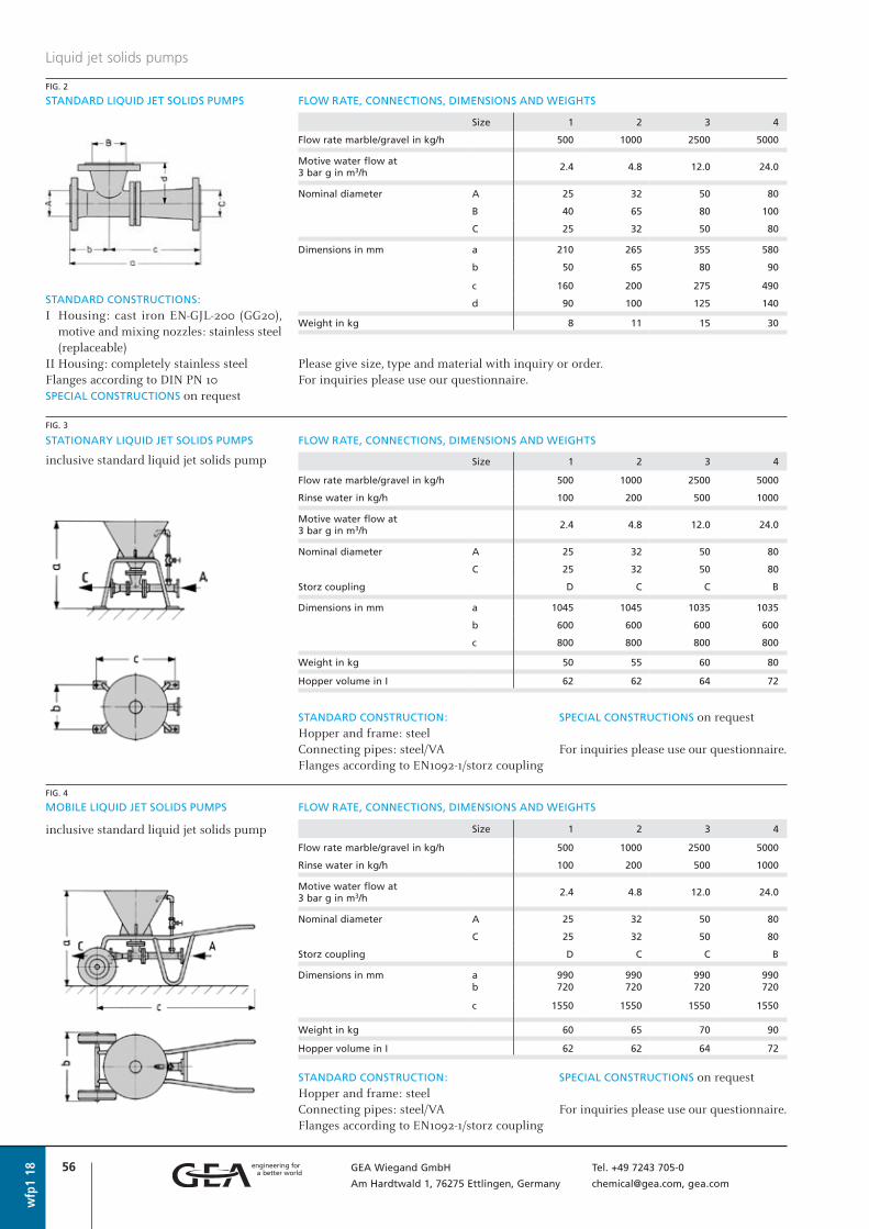
56 GEA Wiegand GmbH Tel. +49 7243 705-0
Am Hardtwald 1, 76275 Ettlingen, Germany [email protected], gea.com
STATIONARY LIQUID JET SOLIDS PUMPS FLOW RATE, CONNECTIONS, DIMENSIONS AND WEIGHTS
inclusive standard liquid jet solids pump
wfp
1 18
Liquid jet solids pumps
Size 1 2 3 4
Flow rate marble/gravel in kg/h 500 1000 2500 5000
Rinse water in kg/h 100 200 500 1000
Motive water flow at 3 bar g in m3/h
2.4 4.8 12.0 24.0
Nominal diameter A 25 32 50 80
C 25 32 50 80
Storz coupling D C C B
Dimensions in mm a 990 990 990 990 b 720 720 720 720
c 1550 1550 1550 1550
Weight in kg 60 65 70 90
Hopper volume in I 62 62 64 72
Size 1 2 3 4
Flow rate marble/gravel in kg/h 500 1000 2500 5000
Motive water flow at 3 bar g in m3/h
2.4 4.8 12.0 24.0
Nominal diameter A 25 32 50 80
B 40 65 80 100
C 25 32 50 80
Dimensions in mm a 210 265 355 580
b 50 65 80 90
c 160 200 275 490
d 90 100 125 140
Weight in kg 8 11 15 30
STANDARD CONSTRUCTIONS:
I Housing: cast iron EN-GJL-200 (GG20), motive and mixing nozzles: stainless steel (replaceable)
II Housing: completely stainless steelFlanges according to DIN PN 10SPECIAL CONSTRUCTIONS on request
Please give size, type and material with inquiry or order. For inquiries please use our questionnaire.
FIG. 2
STANDARD LIQUID JET SOLIDS PUMPS FLOW RATE, CONNECTIONS, DIMENSIONS AND WEIGHTS
Size 1 2 3 4
Flow rate marble/gravel in kg/h 500 1000 2500 5000
Rinse water in kg/h 100 200 500 1000
Motive water flow at 3 bar g in m3/h
2.4 4.8 12.0 24.0
Nominal diameter A 25 32 50 80
C 25 32 50 80
Storz coupling D C C B
Dimensions in mm a 1045 1045 1035 1035
b 600 600 600 600
c 800 800 800 800
Weight in kg 50 55 60 80
Hopper volume in I 62 62 64 72
STANDARD CONSTRUCTION:
Hopper and frame: steelConnecting pipes: steel/VAFlanges according to EN1092-1/storz coupling
SPECIAL CONSTRUCTIONS on request
For inquiries please use our questionnaire.
FIG. 4
FIG. 3
MOBILE LIQUID JET SOLIDS PUMPS FLOW RATE, CONNECTIONS, DIMENSIONS AND WEIGHTS
inclusive standard liquid jet solids pump
STANDARD CONSTRUCTION:
Hopper and frame: steelConnecting pipes: steel/VAFlanges according to EN1092-1/storz coupling
SPECIAL CONSTRUCTIONS on request
For inquiries please use our questionnaire.
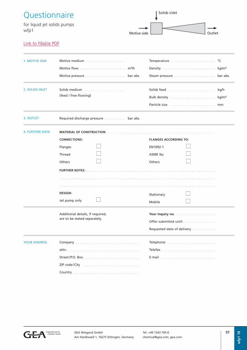
57GEA Wiegand GmbH Tel. +49 7243 705-0
Am Hardtwald 1, 76275 Ettlingen, Germany [email protected], gea.com
wfp
1 18
Questionnairefor liquid jet solids pumps wfp1
Motive medium . . . . . . . . . . . . . . . . . .
Motive flow . . . . . . . . . . . . . . . . . . . . . m³/h
Motive pressure . . . . . . . . . . . . . . . . . . bar abs.
1. MOTIVE SIDE Temperature . . . . . . . . . . . . . . . . . . . . . °C
Density . . . . . . . . . . . . . . . . . . . . . . . . kg/m³
Steam pressure . . . . . . . . . . . . . . . . . . . bar abs.
Solids medium . . . . . . . . . . . . . . . . . . .
(feed / free-flowing)
2. SOLIDS INLET Solids feed . . . . . . . . . . . . . . . . . . . . . . kg/h
Bulk density . . . . . . . . . . . . . . . . . . . . . kg/m³
Particle size . . . . . . . . . . . . . . . . . . . . . mm
MATERIAL OF CONSTRUCTION . . . . . . . . . . . . . . . . . . . . . . . . . . . . . . . . . . . . . . . . . . . . . . . . .
CONNECTIONS:
Flanges
Thread
Others
Required discharge pressure . . . . . . . . . . bar abs.3. OUTLET
FLANGES ACCORDING TO:
EN1092-1
ASME lbs
Others
4. FURTHER DATA
FURTHER NOTES: . . . . . . . . . . . . . . . . . . . . . . . . . . . . . . . . . . . . . . . . . . . . . . . . . . . . . . . . . . .
. . . . . . . . . . . . . . . . . . . . . . . . . . . . . . . . . . . . . . . . . . . . . . . . . . . . . . . . . . . . . . . . . . . . . . .
. . . . . . . . . . . . . . . . . . . . . . . . . . . . . . . . . . . . . . . . . . . . . . . . . . . . . . . . . . . . . . . . . . . . . . .
Additional details, if required, are to be stated separately.
Your inquiry no. . . . . . . . . . . . . . . . . . .
Offer submitted until . . . . . . . . . . . . . . .
Requested date of delivery . . . . . . . . . . .
Company . . . . . . . . . . . . . . . . . . . . . . . . . . . . .
attn. . . . . . . . . . . . . . . . . . . . . . . . . . . . . . . . .
Street/P.O. Box . . . . . . . . . . . . . . . . . . . . . . . . .
ZIP code/City . . . . . . . . . . . . . . . . . . . . . . . . . .
Country . . . . . . . . . . . . . . . . . . . . . . . . . . . . . .
YOUR ADDRESS Telephone . . . . . . . . . . . . . . . . . . . . . .
Telefax . . . . . . . . . . . . . . . . . . . . . . . . .
E-mail . . . . . . . . . . . . . . . . . . . . . . . . .
DESIGN:
Jet pump only
Stationary
Mobile
Link to fillable PDF

58 GEA Wiegand GmbH Tel. +49 7243 705-0
Am Hardtwald 1, 76275 Ettlingen, Germany [email protected], gea.com
wfp
1 18
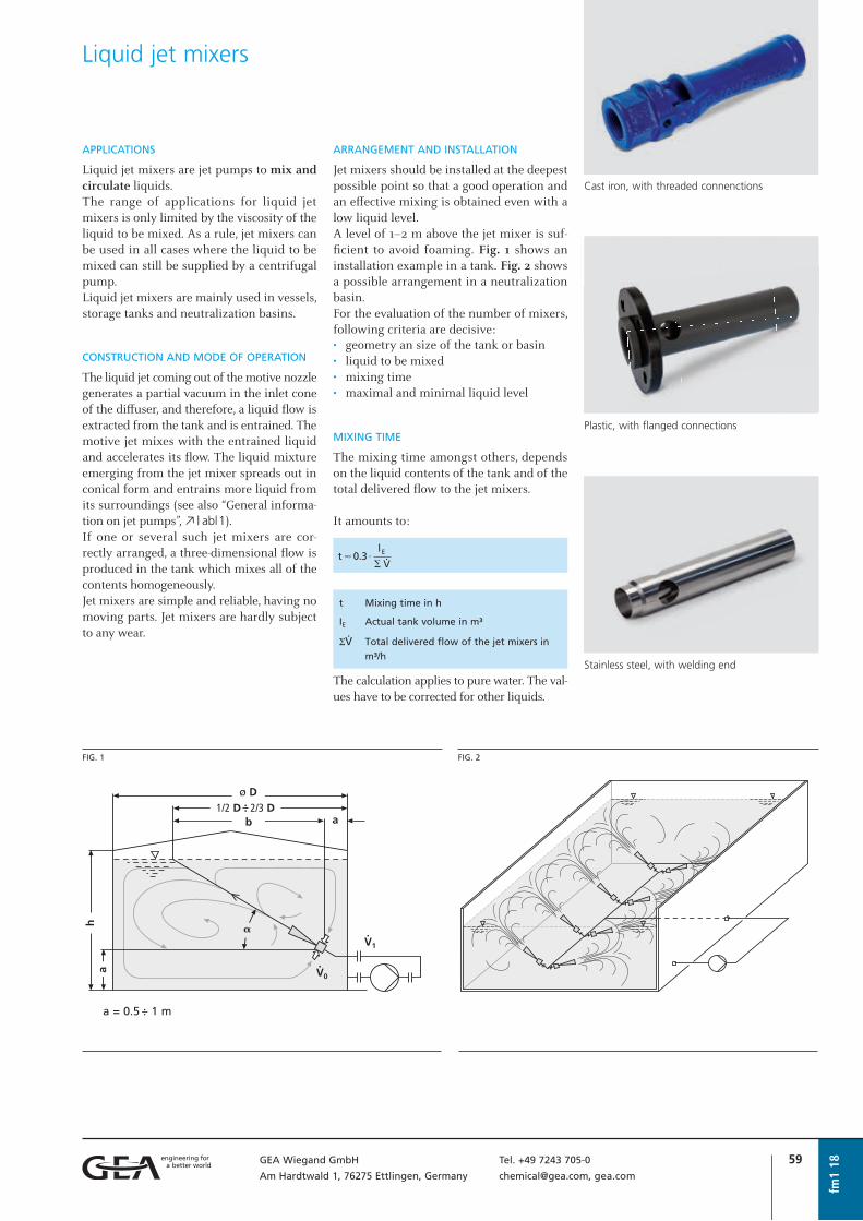
59GEA Wiegand GmbH Tel. +49 7243 705-0
Am Hardtwald 1, 76275 Ettlingen, Germany [email protected], gea.com
fm1
18
APPLICATIONS
Liquid jet mixers are jet pumps to mix and circulate liquids.The range of applications for liquid jet mixers is only limited by the viscosity of the liquid to be mixed. As a rule, jet mixers can be used in all cases where the liquid to be mixed can still be supplied by a centrifugal pump.Liquid jet mixers are mainly used in vessels, storage tanks and neutralization basins.
CONSTRUCTION AND MODE OF OPERATION
The liquid jet coming out of the motive nozzle generates a partial vacuum in the inlet cone of the diff user, and therefore, a liquid fl ow is extracted from the tank and is entrained. The motive jet mixes with the entrained liquid and accelerates its fl ow. The liquid mixture emerging from the jet mixer spreads out in conical form and entrains more liquid from its surroundings (see also “General informa-tion on jet pumps”, o | abl1).If one or several such jet mixers are cor- rectly arranged, a three-dimensional fl ow is produced in the tank which mixes all of the contents homogeneously.Jet mixers are simple and reliable, having no moving parts. Jet mixers are hardly subject to any wear.
ARRANGEMENT AND INSTALLATION
Jet mixers should be installed at the deepest possible point so that a good operation and an eff ective mixing is obtained even with a low liquid level.A level of 1–2 m above the jet mixer is suf-fi cient to avoid foaming. Fig. 1 shows an installation example in a tank. Fig. 2 shows a possible arrangement in a neutralization basin.For the evaluation of the number of mixers, following criteria are decisive:• geometry an size of the tank or basin• liquid to be mixed• mixing time• maximal and minimal liquid level
MIXING TIME
The mixing time amongst others, depends on the liquid contents of the tank and of the total delivered fl ow to the jet mixers.
It amounts to:
t Mixing time in h
IE Actual tank volume in m³
Så Total delivered flow of the jet mixers in
m³/h
The calculation applies to pure water. The val-ues have to be corrected for other liquids.
Liquid jet mixers
Cast iron, with threaded connenctions
Plastic, with fl anged connections
Stainless steel, with welding end
FIG. 2FIG. 1
a = 0.5 :– 1 m
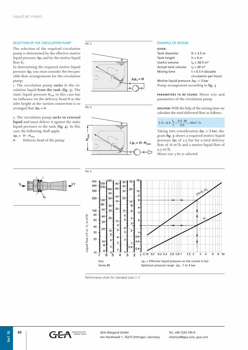
60 GEA Wiegand GmbH Tel. +49 7243 705-0
Am Hardtwald 1, 76275 Ettlingen, Germany [email protected], gea.com
fm1
18
Liquid jet mixers
SELECTION OF THE CIRCULATION PUMP
The selection of the required circulation pump is determined by the effective motive liquid pressure Δp1 and by the motive liquid flow å1.In determining the required motive liquid pressure Δp1 you must consider the two pos-sible flow arrangements for the circulation pump:1. The circulation pump sucks in the cir-culation liquid from the tank (fig. 3). Thestatic liquid pressure Hstat in this case hasno influence on the delivery head H as theinlet height at the suction connection is soarranged that Δp1 = H.
2. The circulation pump sucks in externalliquid and must deliver it against the staticliquid pressure in the tank (fig. 4). In thiscase, the following shall apply:Δp1 = H – Hstat
H Delivery head of the pump
EXAMPLE OF DESIGN
GIVEN:
Tank diameter D = 3.5 m
Tank height h = 4 m
Useful volume IN = 38.5 m3
Actual tank volume IE = 30 m3
Mixing time t = 0.5 h (double
circulation per hour)
Motive liquid pressure Δp1 # 3 bar
Pump arrangement according to fig. 3
PARAMETERS TO BE FOUND: Mixer size and parameters of the circulation pump
SOLUTION: With the help of the mixing time we calculate the total delivered flow as follows:
Taking into consideration Δp1 # 3 bar, dia-gram fig. 5 shows a required motive liquid pressure Δp1 of 2.5 bar for a total delivery flow of 18 m³/h and a motive liquid flow of 4.5 m³/h.Mixer size 3-80 is selected.
FIG. 3
FIG. 4
FIG. 5
Liq
uid
flo
w S
å o
r. å
1 in
m3 /
h
Size
Series 80
Δp1 = Effective liquid pressure on the nozzle in bar
Optimum pressure range ΔΔp1 : 1 to 4 bar
Performance chart for standard sizes 1–7

61GEA Wiegand GmbH Tel. +49 7243 705-0
Am Hardtwald 1, 76275 Ettlingen, Germany [email protected], gea.com
fm1
18
Liquid jet mixers
FIG. 8FIG. 7
Dichte – kg/m3
12701260
1240
1220
1200
1180
1160
1140
1120
1100
1080
1060
1040
1020
1000
CONNECTIONS, DIMENSIONS AND WEIGHTS
LIQUID JET MIXERS WITH THREADED CONNECTIONS TYPE 17.1 LIQUID JET MIXERS WITH FLANGED CONNECTIONS TYPE 27.1
CAST IRON Size 1-80 2-80 3-80 4-80 5-80 6-80 7-80
Motive liquid connection
A G 3/4 G 1 G11/2 G11/2 G 2 G 3 G 4
Dimensions a 170 220 265 345 400 520 610
in mm D 52 60 75 85 100 125 160
f 20 25 24 24 30 33 40
Weight in kg 1 2 3 5 7 13 24
CAST IRON Size 1-80 2-80 3-80 4-80 5-80 6-80 7-80
Motive liquid connection
A 20 25 40 40 50 80 100
Dimensions a 200 250 300 380 440 570 660
in mm D 52 60 75 85 100 125 160
Weight in kg 2 3 5 7 10 19 33
FIG. 6A FIG. 6D
FIG. 6B FIG. 6E
STAINLESS STEEL Size 1-80 2-80 3-80 4-80 5-80 6-80 7-80
Motive liquid connection
A G 3/4 G 1 G11/2 G11/2 G 2 G 3 G 4
Dimensions a 170 220 265 345 400 495 610
in mm D 45 55 55 63 79 112 140
f 20 25 24 25 30 41 50
Weight in kg 1.4 2.8 2.8 4 7 18 31
STAINLESS STEEL Size 1-80 2-80 3-80 4-80 5-80 6-80 7-80
Motive liquid connection
A 20 25 40 40 50 80 100
Dimensions a 170 220 265 345 400 495 610
in mm D 45 55 55 63 79 112 140
Weight in kg 2.2 3.5 4.5 5.5 9 22 35
PLASTICS Size 1-80 2-80 3-80 4-80 5-80 6-80 7-80
Motive liquid connection
A G 3/4 G 1 G11/2 G11/2 G 2 G 3 G 4
Dimensions a 170 220 265 345 400 495 610
in mm D 50 60 70 80 90 120 150
f 20 25 24 25 30 41 50
Weight PVC in kg 0.4 0.7 1 1.5 2 4 7.5
Weight PP in kg 0.3 0.5 0.8 1 1.6 3 5
Weight PTFE in kg 0.5 1 1.5 2.3 3 6 10
FIG. 6C FIG. 6F
PLASTICS Size 1-80 2-80 3-80 4-80 5-80 6-80 7-80
Motive liquid connection
A 20 25 40 40 50 80 100
Dimensions a 170 220 265 345 400 495 610
in mm D 50 60 60 60 76 106 130
Weight in PVC kg 0.4 0.8 0.9 1.3 1.9 3.7 5
Weight in PP kg 0.3 0.6 0.7 1 1.5 3 4
Weight in PTFE kg 0.6 1.2 1.4 2 2.7 5 7
SPECIAL CONSTRUCTIONS regarding material, connections and nominal diameter > DN100 on request.
For inquiries please use our questionnaire.
A numerical fl ow simulation (CFD) as in fi g. 7 and fi g. 8 is available on request.
STANDARD CONSTRUCTIONS: I Completely stainless steel 1.4571, II Completely stainless steel 1.4301, threaded connections according to ISO 228, fl anges according to EN1092-1
STANDARD CONSTRUCTIONS: Housing: cast iron EN-GJL-200 (GG20), nozzles: stainless steel, threaded connections according to ISO 228, fl anges according to EN1092-1
STANDARD CONSTRUCTIONS: I Completely PVC, II Completely PP, III Completely PTFE, threaded connections according to ISO 228
I Completely PVC, loose fl anges: GF-UP, II Completely PP, loose fl anges: GF-UP, III Completely PTFE, fl anges according to EN1092-1

62 GEA Wiegand GmbH Tel. +49 7243 705-0
Am Hardtwald 1, 76275 Ettlingen, Germany [email protected], gea.comfm 1
8
MATERIAL OF CONSTRUCTION . . . . . . . . . . . . . . . . . . . . . . . . . . . . . . . . . . . . . . . . . . . . . . . . .
CONNECTIONS:
Flanges
Thread
Others
FURTHER NOTES: . . . . . . . . . . . . . . . . . . . . . . . . . . . . . . . . . . . . . . . . . . . . . . . . . . . . . . . . . . . . . . . . . . . . . . . . . . . . . . . . .
. . . . . . . . . . . . . . . . . . . . . . . . . . . . . . . . . . . . . . . . . . . . . . . . . . . . . . . . . . . . . . . . . . . . . . . . . . . . . . . . . . . . . . . . . . . . . . . . . .
. . . . . . . . . . . . . . . . . . . . . . . . . . . . . . . . . . . . . . . . . . . . . . . . . . . . . . . . . . . . . . . . . . . . . . . . . . . . . . . . . . . . . . . . . . . . . . . . . .
Questionnairefor liquid jet mixers fm1, fm2
1. DIMENSIONS OF THE TANK OR BASIN
Volume of the tank or basin . . . . . . . . . . m³
Diameter . . . . . . . . . . . . . . . . . . . . . . . mm
Length . . . . . . . . . . . . . . . . . . . . . . . . . mm
Width . . . . . . . . . . . . . . . . . . . . . . . . . mm
Height . . . . . . . . . . . . . . . . . . . . . . . . . mm
Medium . . . . . . . . . . . . . . . . . . . . . . . .
Temperature . . . . . . . . . . . . . . . . . . . . . °C
Density . . . . . . . . . . . . . . . . . . . . . . . . kg/m³
2. LIQUID TO BE MIXED
Dyn. viscosity . . . . . . . . . . . . . . . . . . . . mPas
Solid content . . . . . . . . . . . . . . . . . . . . . g/l
Particle size . . . . . . . . . . . . . . . . . . . . . mm
Liquid flow . . . . . . . . . . . . . . . . . . . . . . m³/h3. CIRCULATION PUMP Pressure at mixer . . . . . . . . . . . . . . . . . bar g
Mixing time . . . . . . . . . . . . . . . . . . . . . h4. MIXING REQUIREMENTS
Further requirements . . . . . . . . . . . . . . . . . . . . . . . . . . . . . . . . . . . . . . . . . . . . . . . . . . . . . . .
. . . . . . . . . . . . . . . . . . . . . . . . . . . . . . . . . . . . . . . . . . . . . . . . . . . . . . . . . . . . . . . . . . . . . . .
. . . . . . . . . . . . . . . . . . . . . . . . . . . . . . . . . . . . . . . . . . . . . . . . . . . . . . . . . . . . . . . . . . . . . . .
Additional details, if required, are to be stated separately.
Your inquiry no. . . . . . . . . . . . . . . . . . .
Offer submitted until . . . . . . . . . . . . . .
Requested date of delivery . . . . . . . . . . .
5. FURTHER DATA
FLANGES ACCORDING TO:
EN1092-1
ASME lbs
Others
Company . . . . . . . . . . . . . . . . . . . . . . . . . . . . .
attn. . . . . . . . . . . . . . . . . . . . . . . . . . . . . . . . .
Street/P.O. Box . . . . . . . . . . . . . . . . . . . . . . . . .
ZIP code/City . . . . . . . . . . . . . . . . . . . . . . . . . .
Country . . . . . . . . . . . . . . . . . . . . . . . . . . . . . .
YOUR ADDRESS Telephone . . . . . . . . . . . . . . . . . . . . . .
Telefax . . . . . . . . . . . . . . . . . . . . . . . . .
E-mail . . . . . . . . . . . . . . . . . . . . . . . . .
Link to fillable PDF
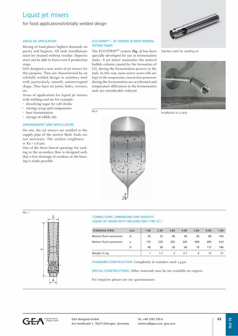
63GEA Wiegand GmbH Tel. +49 7243 705-0
Am Hardtwald 1, 76275 Ettlingen, Germany [email protected], gea.com
Liquid jet mixersfor food applications/orbitally welded design
fm2
18 STAINLESS STEEL Size 1-80 2-80 3-80 4-80 5-80 6-80 7-80
Motive fluid connection A 20 25 40 40 50 80 100
Motive fluid connection a 170 220 265 345 400 495 610
D 40 50 50 60 79 112 140
Weight in kg 1 1.7 2 2.7 6 15 27
CONNECTIONS, DIMENSIONS AND WEIGHTS
LIQUID JET MIXER WITH WELDING END TYPE 37.1
FIG. 1
STANDARD CONSTRUCTION: Completely in stainless steel 1.4301
SPECIAL CONSTRUCTIONS: Other materials may be are available on request.
For inquiries please use our questionnaire.
AREAS OF APPLICATION
Mixing of food places highest demands on purity and hygiene. All tank installations must be cleaned without residue. Deposits must not be able to form even if production stops.GEA designed a new series of jet mixers for this purpose. They are characterized by an orbitally welded design in stainless steel with particularly smooth, uninterrupted shape. They have no joints, holes, crevices, etc.Areas of application for liquid jet mixers with welding end are for example:• dissolving sugar for soft drinks• mixing syrup and components• beer fermentation• storage of edible oils
ARRANGEMENT AND INSTALLATION
On site, the jet mixers are welded to the supply pipe of the motive fl uid. Seals are not necessary. The surface roughness is Ra < 0.8 µm.One of the three lateral openings for suck-ing in the secondary fl ow is designed such that a free drainage of residues in the hous-ing is made possible.
Installation in a tank
Stainless steel for welding on
ECO-FERMTM – JET MIXERS IN BEER FERMEN-
TATION TANKS
The ECO-FERMTM system (fi g. 2) has been specially developed for use in fermentation tanks. A jet mixer maintains the natural bubble column caused by the formation of CO2 during the fermentation process in the tank. In this way, more active yeast cells are kept in the suspension, conversion processes during the fermentation are accelerated and temperature diff erences in the fermentation tank are considerably reduced.
FIG 2

64 GEA Wiegand GmbH Tel. +49 7243 705-0
Am Hardtwald 1, 76275 Ettlingen, Germany [email protected], gea.com
fm2
18

65GEA Wiegand GmbH Tel. +49 7243 705-0
Am Hardtwald 1, 76275 Ettlingen, Germany [email protected], gea.com
Liquid jet ventilators
fv1
18
APPLICATIONS
Liquid jet ventilators are used to draw off air, gases or vapor.They are designed to suck in gas flows at small pressure differences. The pressure gain (compression) which these units can archive is in the range between 1 and 20 mbar.
MODE OF OPERATION
Liquid jet ventilators operate on the jet pumps principle (“General information on jet pumps”, o | abl1). Their action is basedon the jet of motive liquid which emerges from the motive nozzle entraining and con-veying the surrounding gas.
OPERATING CHARACTERISTICS
The specific motive liquid requirement in m³ of liquid per m³ of air or gas• decreases with higher motive liquid
pressure p1
• increases with rising, requiredcompression Δp
• is independent of nature and density offthe drawn off gases
ADVANTAGES
• with correct choice of materials ofmanu facture an almost unlimited life
• no moving parts• maintenance-free• quickly and simply brought into
operation• can be fabricated from many different
materials• low capital and installation costs• low-noise operation
EXAMPLE OF DESIGN
A liquid jet ventilator has to convey approx-imately 400 m³/h air. The available motive water pressure is 3 bar g.PARAMETERS TO BE FOUND:
1. Maximum compression Δp in mbar2. Size of ventilator3. Motive liquid consumption in m³/hSOLUTION: Fig. 1 shows that a ventilator size4 produces a compression of Δp = 5 mbar.The operating point lies within the area ofbest efficiency. Therefore the ventilator issuitable for the required duty.
From fig. 2 we find a motive liquid con-sumption of 4.4 m³/h.
Co
mp
ress
ion
Δp
= p
–p0
in m
bar
Size
Air suction flow å0 in m3/h
Series 80
FIG. 1
p1 = Motive liquid pressure in bar
p0 = Suction pressure in bar
p = Discharge pressure in bar
å1 = Motive liquid flow in m3/h
å0 = Gas suction flow in m3/h
å = Mixed flow in m3/h
hmax. = Optimum working efficiency
(Pressure indications in bar = bar g)
å1
p1
å
p
å0, p0

66 GEA Wiegand GmbH Tel. +49 7243 705-0
Am Hardtwald 1, 76275 Ettlingen, Germany [email protected], gea.com
Liquid jet ventilators
fv1
18
Motive liquid pressure p1 in barSize
Mo
tive
liq
uid
co
nsu
mp
tio
n å
1 in
m3 /
h Series 80
Pressure indications
in bar = bar g
FIG. 2
CONNECTIONS, DIMENSIONS AND WEIGHTS
SERIES 80 Size 1 2 3 4 5 6 7
Motive liquid connection A 15 25 25 32 32 50 65
Suction connection B 50 65 100 125 150 200 250
Pressure connection C 50 65 100 125 150 200 250
Dimensions in mm a 1025 1300 1750 2000 2350 2750 3000
c 925 1175 1625 1875 2125 2600 2850
d 150 175 200 225 250 300 325
Weight in kg
Steel 9 14 34 50 77 148 220
Stainless steel 9 14 28 37 51 75 105
Plastic material (PP) 4 5 8 11 15 18 25
STANDARD CONSTRUCTIONS:
I Housing: steel, motive nozzle: bronze, twist piece: PVCII Completely stainless steel 1.4571III Completely stainless steel 1.4541IV Completely PVC, loose flanges: GRPV Completely PP, loose flanges: GRPFlanges according to EN1092-1
SPECIAL CONSTRUCTIONS: Titanium, Hastelloy, glass-fibre reinforced plastic (GFK) etc.
For special constructions dimensional modifications are subject to change.When ordering standard units size, type and materials of construction should be given.
For inquiries please use our questionnaire.
FIG. 3

67GEA Wiegand GmbH Tel. +49 7243 705-0
Am Hardtwald 1, 76275 Ettlingen, Germany [email protected], gea.com
fv1
18
Questionnairefor liquid jet ventilators fv1
Motive medium . . . . . . . . . . . . . . . . . .
Motive flow . . . . . . . . . . . . . . . . . . . . . m³/h
Motive pressure . . . . . . . . . . . . . . . . . . bar abs.
1. MOTIVE SIDE Temperature . . . . . . . . . . . . . . . . . . . . . °C
Density . . . . . . . . . . . . . . . . . . . . . . . . kg/m³
Concentration . . . . . . . . . . . . . . . . . . . weight %
Steam pressure . . . . . . . . . . . . . . . . . . . bar abs.
Suction medium . . . . . . . . . . . . . . . . . .
Suction flow . . . . . . . . . . . . . . . . . . . . . m³/h
Suction pressure . . . . . . . . . . . . . . . . . . bar abs.
2. SUCTION SIDE Temperature . . . . . . . . . . . . . . . . . . . . . °C
Density . . . . . . . . . . . . . . . . . . . . . . . . kg/m³
Concentration . . . . . . . . . . . . . . . . . . . weight %
Required discharge pressure . . . . . . . . . . bar abs.3. OUTLET Concentration . . . . . . . . . . . . . . . . . . . weight %
MATERIAL OF CONSTRUCTION . . . . . . . . . . . . . . . . . . . . . . . . . . . . . . . . . . . . . . . . . . . . . . . . .
CONNECTIONS:
Flanges
Thread
Others
Company . . . . . . . . . . . . . . . . . . . . . . . . . . . . .
attn. . . . . . . . . . . . . . . . . . . . . . . . . . . . . . . . .
Street/P.O. Box . . . . . . . . . . . . . . . . . . . . . . . . .
ZIP code/City . . . . . . . . . . . . . . . . . . . . . . . . . .
Country . . . . . . . . . . . . . . . . . . . . . . . . . . . . . .
YOUR ADDRESS Telephone . . . . . . . . . . . . . . . . . . . . . .
Telefax . . . . . . . . . . . . . . . . . . . . . . . . .
E-mail . . . . . . . . . . . . . . . . . . . . . . . . .
FLANGES ACCORDING TO:
EN1092-1
ASME lbs
Others
4. FURTHER DATA
DESIGN CODE (if required):
AD-2000
ASME
Others
APPLICATION:
. . . . . . . . . . . . . . . . . . . . . . . . . . . . . .
. . . . . . . . . . . . . . . . . . . . . . . . . . . . . .
. . . . . . . . . . . . . . . . . . . . . . . . . . . . . .
DESIGN:
Temperature . . . . . . . . . . . . . . . . . . . . . °C Pressure . . . . . . . . . . . . . . . . . . . . . . . . bar g
FURTHER NOTES: . . . . . . . . . . . . . . . . . . . . . . . . . . . . . . . . . . . . . . . . . . . . . . . . . . . . . . . . . . .
. . . . . . . . . . . . . . . . . . . . . . . . . . . . . . . . . . . . . . . . . . . . . . . . . . . . . . . . . . . . . . . . . . . . . . .
. . . . . . . . . . . . . . . . . . . . . . . . . . . . . . . . . . . . . . . . . . . . . . . . . . . . . . . . . . . . . . . . . . . . . . .
Additional details, if required, are to be stated separately.
Your inquiry no. . . . . . . . . . . . . . . . . . .
Offer submitted until . . . . . . . . . . . . . .
Requested date of delivery . . . . . . . . . . .
Link to fillable PDF
68 GEA Wiegand GmbH Tel. +49 7243 705-0
Am Hardtwald 1, 76275 Ettlingen, Germany [email protected], gea.com
fv1
18

Grundlagen und Arbeitsblätter
• Steam jet vacuum pumps
• Steam jet compressors (thermo compressors)
• Steam jet ventilators
• Steam jet liquid pumps, general information
• Steam jet liquid pumps class A
• Steam jet liquid pumps class B
• Steam jet heaters, general information
• Steam jet heaters for vessels
• Steam jet heaters “L” for installation in pipelines
• Steam jet heaters “H” for passage and circulation heating systems
• Steam jet heaters “System Ciba-Geigy” for passage and circulationheating systems
Grundlagen und ArbeitsblätterSteam jet pumps

fv1
18

71GEA Wiegand GmbH Tel. +49 7243 705-0
Am Hardtwald 1, 76275 Ettlingen, Germany [email protected], gea.com
dvp1
18
Steam jet pumps are particularly appropri-ate as vacuum pumps, as they can easily handle large vacuum volumes.Single stage jet pumps, which convey against atmospheric pressure are used for the production of vacuum down to a suction pressure of approx. 100 mbar.For lower suction pressures multi-stage steam jet vacuum pumps are used, with or without intermediate condensation. For more details, please refer to section “Vacuum systems”, o | gdp1.
ADVANTAGES
• no moving parts• easy handling of even very large suction
flows• low maintenance cost• long life• high reliability and safety of operation• low priced, low operating cost• manufacture from various materials of
construction
DESIGN
Steam jet vacuum pumps have a tailor-made design depending on the individual require-ments. In this way optimum efficiency is achieved.
PERFORMANCE CHART FOR VACUUM PUMPS
EXAMPLE
It is required to extract Ø0 = 50 kg/h of air at 20 °C from a suction pressure of p0 = 200 mbar. A motive steam pressure ofp1 = 10 bar g is available.From the diagrams fig. 1 and fig. 2, the required motive steam flow as well as the suction connection diameter can be ascer-tained in relation to the suction pressure and suction flow. The overall dimensions of the equipment are fixed in relation to the suction connec-tion diameter.
Fig. 1 shows a specific steam consumption of
The steam consumption is, therefore,
In fig. 2 the operating point suction flow = 50 g/h and
suction pressure = 200 mbar is between the curves for DN 40 and DN 50.
DN 50 is chosen as the curves in fig. 2 give the maximum possible suction flow for each particular size. The dimensions of the required jet pump, in various materials of construction, are given in fig. 9 and 10.
The diagrams fig. 1 and 2 are valid for a suc-tion medium of air at 20 °C. At other suction temperatures, but at the same suction pres-sure, the suction flow is calculated according to the following equation:
If water vapor, instead of air, is to be drawn off, the suction flow is approx. 80 % of the values given in diagram fig. 2. For other gases or vapors see section “Equivalent suction flows for steam jet vacuum pumps”, o | abl12.
Steam jet vacuum pump in metal
Steam jet vacuum pump in graphite
Steam jet vacuum pumpsSp
ecif
ic s
team
co
nsu
mp
tio
n μ
in k
g s
team
/ kg
air
Specific steam consumption of a single stage steam jet vacuum pump when compressing to atmosphere (1013 mbar)
Suction pressure p0 in mbar
Suction pressure p0 in mbar
Suct
ion
flow
Ø0
in k
g/h
air
*
M = Metal construction
P = Porcelain construction
*) approx. value dependent on motive steam pressure (10 bar)
Maximum possible suction flow in kg/h for air at 20 °C
FIG. 2
FIG. 1
p1 = Motive steam
pressure gauge

72 GEA Wiegand GmbH Tel. +49 7243 705-0
Am Hardtwald 1, 76275 Ettlingen, Germany [email protected], gea.com
PRE-EVACUATION
If a plant is to be evacuated within a given time, for example, during start-up, and the vacuum pump which maintains the opera-tional vacuum takes longer than the given time, a jet pump is added to speed up the evacuation. This jet pump is called pre-evac-uator or start-up jet pump.
This pump is brought into operation togeth-er with the vacuum pump, but works only until the required vacuum, or a determined intermediate vacuum is reached (see also section “Vacuum systems, Planning of a steam jet vacuum pump”, o | gdp3).
In order to determine whether a pre-evacu-ator is required, the evacuation time of the vacuum pump has to be calculated with the help of the following formulas:
in minutes.
Where:
V Volume of the plant to be evacuated in m³
p0 Required operating vacuum
(suction pressure) in mbar
ØA Air suction flow in kg/h, for which the
steam jet vacuum pump is designed
From the result obtained, it can be estimated whether a pre-evacuator is required.Single-stage start-up jet pumps can, accord-ing to the motive steam pressure, achieve a final pressure of approx. 80 mbar.For lower pressures a two-stage start-up jet pump must be used.
PERFORMANCE CHART FOR PRE-EVACUATORS
EXAMPLE
A vessel with a volume of 31 m³ is to be evacuated from 1000 mbar to 80 mbar in 15 minutes. Motive steam at 10 bar g is avail-able.From fig. 4 for 80 mbar and 10 bar g one finds a specific motive steam consumption of 2.28 kg motive steam/m³ volume to be evacuated.The steam consumption is then calculated with the aid of the following formula:
ØD Steam consumption in kg/h
Dspec. kg motive steam/m³ volume to be
evacuated
V Volume of the plant to be evacuated
in m³
t Required evacuation time in minutes
Fig. 5 gives the nominal diameter of the pre-evacuator required for this steam con-sumption. The example given requires a pre-evacuator DN 80 I.
dvp1
18
Steam jet vacuum pumps
FIG. 3
1 Steam jet vacuum pump as pre-evacuator
2 Two-stage steam jet vacuum pump
3 Column head
4 Column
I Separator
II Mixing condenser
A Motive steam
B Suction flow
C Cooling water
p1 = Motive steam pressure gauge
Spec. steam consumption Dspec. in kg motive steam/m3 of
plant volume to be evacuated
Fin
al v
acu
um
of
the
pre
-eva
cuat
or
in m
bar
No
min
al s
ize
of
the
pre
-eva
cuat
ors
Motive steam consumption in kg/h
FIG. 4
FIG. 5
Pre-evacuation of a vacuum plant
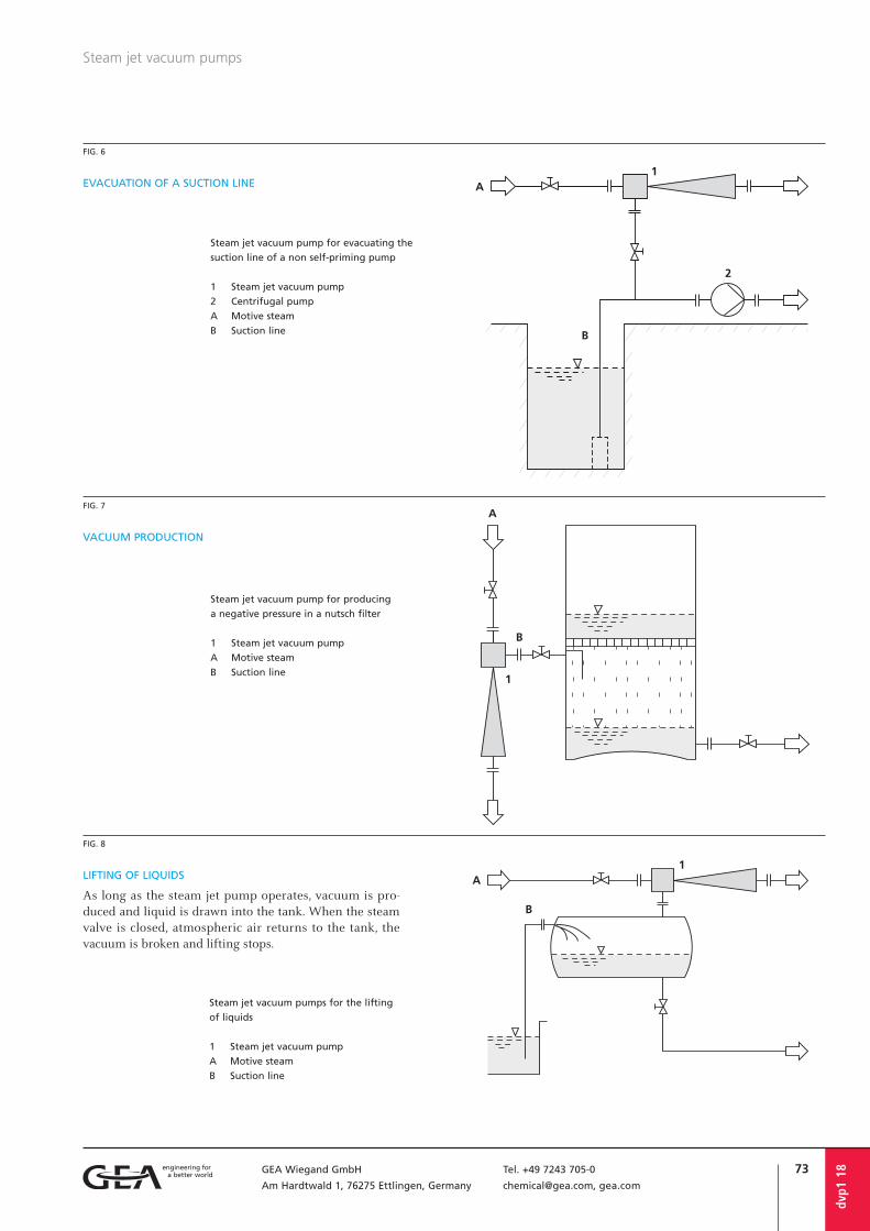
73GEA Wiegand GmbH Tel. +49 7243 705-0
Am Hardtwald 1, 76275 Ettlingen, Germany [email protected], gea.com
dvp1
18
Steam jet vacuum pumps
VACUUM PRODUCTION
LIFTING OF LIQUIDS
As long as the steam jet pump operates, vacuum is pro-duced and liquid is drawn into the tank. When the steam valve is closed, atmospheric air returns to the tank, the vacuum is broken and lifting stops.
FIG. 6
FIG. 7
FIG. 8
EVACUATION OF A SUCTION LINE
Steam jet vacuum pump for evacuating the
suction line of a non self-priming pump
1 Steam jet vacuum pump
2 Centrifugal pump
A Motive steam
B Suction line
Steam jet vacuum pump for producing
a negative pressure in a nutsch filter
1 Steam jet vacuum pump
A Motive steam
B Suction line
Steam jet vacuum pumps for the lifting
of liquids
1 Steam jet vacuum pump
A Motive steam
B Suction line

74 GEA Wiegand GmbH Tel. +49 7243 705-0
Am Hardtwald 1, 76275 Ettlingen, Germany [email protected], gea.com
dvp1
18
Steam jet vacuum pumps
DN 25 25 50 50 80 80
I II I II I II
Steam connection DN 25 25 25 25 40 40
Dimensions in mm a 210 300 440 550 750 930
b 30 30 50 50 90 90
c 100 100 110 110 175 175
d 180 270 390 500 660 840
Weight in kg (approx.) 6 7 18 21 43 46
FIG. 9
CONNECTIONS, DIMENSIONS AND WEIGHTSSTEAM JET VACUUM PUMPS,
METAL CONSTRUCTION
STANDARD CONSTRUCTIONS:
I Housing: cast iron EN-GJL-400-15 (GGG40), motive nozzle: stainless steel
II Housing: cast stainless steel (1.4581), motive nozzle: stainless steel
DN 25 und 50: housing and diff usor screwedDN 80: housing and diff usor fl anged, diff u-sor weldedFlanges according to EN1092-1 or ASME 150 lbs
If necessary the steam jet vacuum pumps can also be manufactured in other sizes, constructions and materials and fl anges of other nominal pressures and standards can be supplied. This, however, does not apply to pumps of porcelain.
The exact installation dimensions of the pumps depend on the operating conditions. For jet pumps according to the design given in fi g. 9, two diff erent dimensions for each size are given.For large nominal diameters jet pumps are designed in welded construction. The dimensions are adapted to the particular conditions.The dimensions are given in the quotation on request (see also “Steam jet compres-sors”, o | bv1)
SPECIAL CONSTRUCTIONS and larger nomi-nal bores on request.Dimensions, connection dimensions and special performance data on request.
For inquiries please use our questionnaire.
DN 32 40 50 65 80 100 125
Dimensions in mm a 320 405 510 653 810 1035 1270
b 90 100 100 130 145 160 170
c 95 110 110 120 135 150 175
d 230 305 410 523 665 875 1100
k 95 120 140 160 185 210 235
D 115 144 164 188 217 242 267
Weight in kg (approx.) 5 8 11 17 21 40 53
STANDARD CONSTRUCTION:
Housing: temperature-change resistant graphiteMotive nozzle: PTFE/GFKConnection clamps: aluminium castSteam connections: steel galvanized
SPECIAL CONSTRUCTIONS with diff erent connections, nominal pressure stages of the fl anges: materials on request.
FIG. 10
CONNECTIONS, DIMENSIONS AND WEIGHTSSTEAM JET VACUUM PUMPS,
GRAPHITE CONSTRUCTION
(Replacement for porcelain construction)
The motive nozzle connections are not given in the above overview as they depend on the operating conditions.
For inquiries please use our questionnaire.
REALIZED JET PUMP
Steam jet vacuum pump in stainless steel
(new construction with flanges acc. to EN1092) DN 25 50 80 100
Dimensions in mm a 360 600 985 1320
b 90 100 145 160
c 100 110 135 150
d 270 500 840 1150
Weight in kg (approx.) 5 11 21 40
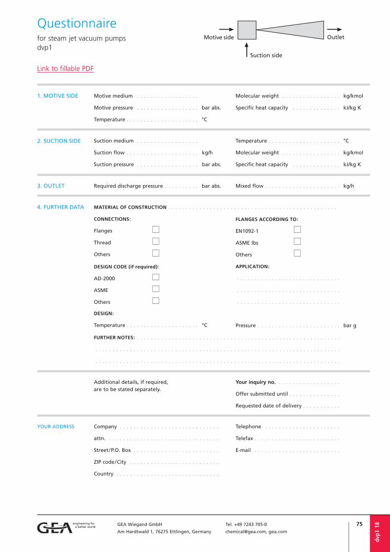
75GEA Wiegand GmbH Tel. +49 7243 705-0
Am Hardtwald 1, 76275 Ettlingen, Germany [email protected], gea.com
dvp1
18
Questionnairefor steam jet vacuum pumps dvp1
Motive medium . . . . . . . . . . . . . . . . . .
Motive pressure . . . . . . . . . . . . . . . . . . bar abs.
Temperature . . . . . . . . . . . . . . . . . . . . . °C
1. MOTIVE SIDE Molecular weight . . . . . . . . . . . . . . . . . kg/kmol
Specific heat capacity . . . . . . . . . . . . . . kJ/kg K
Suction medium . . . . . . . . . . . . . . . . . .
Suction flow . . . . . . . . . . . . . . . . . . . . . kg/h
Suction pressure . . . . . . . . . . . . . . . . . . bar abs.
2. SUCTION SIDE Temperature . . . . . . . . . . . . . . . . . . . . . °C
Molecular weight . . . . . . . . . . . . . . . . . kg/kmol
Specific heat capacity . . . . . . . . . . . . . . kJ/kg K
Required discharge pressure . . . . . . . . . . bar abs.3. OUTLET Mixed flow . . . . . . . . . . . . . . . . . . . . . . kg/h
Additional details, if required, are to be stated separately.
Your inquiry no. . . . . . . . . . . . . . . . . . .
Offer submitted until . . . . . . . . . . . . . . .
Requested date of delivery . . . . . . . . . . .
MATERIAL OF CONSTRUCTION . . . . . . . . . . . . . . . . . . . . . . . . . . . . . . . . . . . . . . . . . . . . . . . . .
CONNECTIONS:
Flanges
Thread
Others
4. FURTHER DATA
DESIGN CODE (if required):
AD-2000
ASME
Others
APPLICATION:
. . . . . . . . . . . . . . . . . . . . . . . . . . . . . .
. . . . . . . . . . . . . . . . . . . . . . . . . . . . . .
. . . . . . . . . . . . . . . . . . . . . . . . . . . . . .
DESIGN:
Temperature . . . . . . . . . . . . . . . . . . . . . °C Pressure . . . . . . . . . . . . . . . . . . . . . . . . bar g
FURTHER NOTES: . . . . . . . . . . . . . . . . . . . . . . . . . . . . . . . . . . . . . . . . . . . . . . . . . . . . . . . . . . .
. . . . . . . . . . . . . . . . . . . . . . . . . . . . . . . . . . . . . . . . . . . . . . . . . . . . . . . . . . . . . . . . . . . . . . .
. . . . . . . . . . . . . . . . . . . . . . . . . . . . . . . . . . . . . . . . . . . . . . . . . . . . . . . . . . . . . . . . . . . . . . .
FLANGES ACCORDING TO:
EN1092-1
ASME lbs
Others
Company . . . . . . . . . . . . . . . . . . . . . . . . . . . . .
attn. . . . . . . . . . . . . . . . . . . . . . . . . . . . . . . . .
Street/P.O. Box . . . . . . . . . . . . . . . . . . . . . . . . .
ZIP code/City . . . . . . . . . . . . . . . . . . . . . . . . . .
Country . . . . . . . . . . . . . . . . . . . . . . . . . . . . . .
YOUR ADDRESS Telephone . . . . . . . . . . . . . . . . . . . . . .
Telefax . . . . . . . . . . . . . . . . . . . . . . . . .
E-mail . . . . . . . . . . . . . . . . . . . . . . . . .
Link to fillable PDF

76 GEA Wiegand GmbH Tel. +49 7243 705-0
Am Hardtwald 1, 76275 Ettlingen, Germany [email protected], gea.com
bv1
18
Questionnairefor steam jet compressors (thermo compressors) bv1
Motive medium . . . . . . . . . . . . . . . . . .
Motive pressure . . . . . . . . . . . . . . . . . . bar abs.
Temperature . . . . . . . . . . . . . . . . . . . . . °C
1. MOTIVE SIDE Molecular weight . . . . . . . . . . . . . . . . . kg/kmol
Specific heat capacity . . . . . . . . . . . . . . kJ/kg K
Suction medium . . . . . . . . . . . . . . . . . .
Suction flow . . . . . . . . . . . . . . . . . . . . . kg/h
Suction pressure . . . . . . . . . . . . . . . . . . bar abs.
2. SUCTION SIDE Temperature . . . . . . . . . . . . . . . . . . . . . °C
Molecular weight . . . . . . . . . . . . . . . . . kg/kmol
Specific heat capacity . . . . . . . . . . . . . . kJ/kg K
Required discharge pressure . . . . . . . . . . bar abs.3. OUTLET Mixed flow . . . . . . . . . . . . . . . . . . . . . . kg/h
Additional details, if required, are to be stated separately.
Your inquiry no. . . . . . . . . . . . . . . . . . .
Offer submitted until . . . . . . . . . . . . . . .
Requested date of delivery . . . . . . . . . . .
MATERIAL OF CONSTRUCTION . . . . . . . . . . . . . . . . . . . . . . . . . . . . . . . . . . . . . . . . . . . . . . . . .
CONNECTIONS:
Flanges
Thread
Others
4. FURTHER DATA
DESIGN CODE (if required):
AD-2000
ASME
Others
APPLICATION:
. . . . . . . . . . . . . . . . . . . . . . . . . . . . . .
. . . . . . . . . . . . . . . . . . . . . . . . . . . . . .
. . . . . . . . . . . . . . . . . . . . . . . . . . . . . .
DESIGN:
Temperature . . . . . . . . . . . . . . . . . . . . . °C Pressure . . . . . . . . . . . . . . . . . . . . . . . . bar g
FURTHER NOTES: . . . . . . . . . . . . . . . . . . . . . . . . . . . . . . . . . . . . . . . . . . . . . . . . . . . . . . . . . . .
. . . . . . . . . . . . . . . . . . . . . . . . . . . . . . . . . . . . . . . . . . . . . . . . . . . . . . . . . . . . . . . . . . . . . . .
. . . . . . . . . . . . . . . . . . . . . . . . . . . . . . . . . . . . . . . . . . . . . . . . . . . . . . . . . . . . . . . . . . . . . . .
FLANGES ACCORDING TO:
EN1092-1
ASME lbs
Others
Company . . . . . . . . . . . . . . . . . . . . . . . . . . . . .
attn. . . . . . . . . . . . . . . . . . . . . . . . . . . . . . . . .
Street/P.O. Box . . . . . . . . . . . . . . . . . . . . . . . . .
ZIP code/City . . . . . . . . . . . . . . . . . . . . . . . . . .
Country . . . . . . . . . . . . . . . . . . . . . . . . . . . . . .
YOUR ADDRESS Telephone . . . . . . . . . . . . . . . . . . . . . .
Telefax . . . . . . . . . . . . . . . . . . . . . . . . .
E-mail . . . . . . . . . . . . . . . . . . . . . . . . .
Link to fillable PDF

77GEA Wiegand GmbH Tel. +49 7243 705-0
Am Hardtwald 1, 76275 Ettlingen, Germany [email protected], gea.com
MODE OF OPERATION
Steam jet compressors use the energy of a vapor fl ow Ø1, of a high pressure level p1 and compress a vapor fl ow Ø0 of low pressure level p0 to a medium pressure level p. Normally, such steam jet compressors are operated by water steam as motive and suction fl uid. Basically, however, steam jet compressors can be operated with any vapor.Further information can be found in chap-ter “General information on jet pumps”, o | abl1.
ADVANTAGES
• large vapor volumes, particularly in highvacuum ranges, are easily handled
• low investment cost due to the relativelysimple construction
• long operational life expectancy as steamjet compressors can always be constructedof a suitable corrosion resistant material
• high operational safety and low mainte-nance as no moving parts are involved
In relation to these advantages, the effi cien-cy does not play signifi cant role, compared to other compressors. As a result of it being custom built for a duty, with correct design and application a high operating effi ciency can be achieved.
APPLICATIONS
Steam jet compressors are used in evapo-rating, distillation, cooling, crystallisation, deodorisation, degassing and drying under vacuum.In the positive pressure range the com-pressed exhaust vapors are used for heating (heat pump).
OPERATIONAL BEHAVIOUR OF STEAM JET
COMPRESSORS
A steam jet compressor must be constructed to unite the operating conditions accurate-ly, otherwise the effi ciency will be poor or it will not work at all. Even so, for a better understanding of the method of operation of steam jet compression, it is important to consider behaviour under varying operating conditions.
BEHAVIOUR UNDER VARYING OPERATION
CONDITIONS
1. If the motive steam pressure changes, thesteam consumption changes proportion-ally to the motive steam pressure. At thenominal value of the motive steam pres-sure, the steam consumption correspondsto the calculated fi gure given in the speci-fi cation. Please also see “Steam consump-tion of jet pumps”, o | abl13.
2. Changes in a motive steam fl ow by chang-ing the motive pressure (or by insertingsteam nozzles with diff erent hole diam-eters) primarily aff ect the discharge pres-sure against which the steam jet compres-sor is able to deliver. An increase of themotive steam fl ow results in an increasein the possible discharge pressure andvice versa. Fig. 2 would show the increase of themotive steam pressure if the dotted line(discharge pressure limits) was movedfurther to the right.
3. If the discharge pressure between thesuction pressure and the discharge pres-sure limit (dotted line) changes whilst
bv1
18
Steam jet compressors (thermo compressors)
FIG. 1
the suction pressure remains constant, the suction fl ow also remains constant as shown by the horizontal curves. If the discharge pressure is raised beyond the discharge pressure limit whilst the suc-tion pressure remains constant, the suc-tion fl ow abruptly drops to zero in case of higher compression.
4. If the suction flow is changed, the jetpump will react with a change in thesuction pressure. A smaller suction fl owresults in a lower suction pressure (bettervacuum) and vice versa.
Fig. 2 shows the relationship between suction fl ow Ø0, suction pressure p0 and discharge pressure p at a constant motive steam pres-sure p1. If two of the three variables Ø0, p0 and p are fi xed variables on the compressor, the resulting third variable is in accordance with the graph.
Suction pressure p0 and discharge
pressure p in mbar
Mas
s su
ctio
n f
low
Ø0
in k
g/h p1 = Motive steam pressure
FIG. 2
The graph has only qualitative validity. The numerical values are only inserted to give a better understanding.
Thermo compressor in steel

78 GEA Wiegand GmbH Tel. +49 7243 705-0
Am Hardtwald 1, 76275 Ettlingen, Germany [email protected], gea.com
bv1
18
ADJUSTMENT OF STEAM JET COMPRESSORS
There are various possibilities to adjust steam jet compressors to suit varying oper-ating conditions:
1. CHANGING THE MOTIVE NOZZLE(S)
A limited adaptation of the steam consump-tion to a varying discharge pressure (e.g. due to a varying cooling water temperature) is possible by altering the motive steam pres-sure or by changing the motive nozzles.
2. THROTTLING THE MOTIVE STEAM
If a sufficiently high motive steam pressure is available, the steam consumption can be adjusted to suit a varying discharge pressure by throttling. This can be done by hand or by automatic control.For example, the steam jet compressor deliv-ers into a mixing condenser, operated with recycled water. A great amount of motive steam can be saved by using steam pressure control of the motive steam as the tempera-ture of the circulating water varies consider-ably in the course of the year.
3. USING NOZZLE NEEDLES
The motive flow is changed by reducing the cross section of the motive nozzle by means
of a nozzle needle. This is done pneumati-cally or by electric positioner. Controllable steam jet compressors with spindle noz-zles are used for fluctuating suction or mix-ing flow and constant or varying suction or discharge pressure. The economical use and satisfactory operation of a controlla-ble jet pump is possible for an expansion ratio under 10 up to maximum 20, where-as the expansion ratio E = p1/p0. Please also see “Steam consumption of jet pumps”, o | abl13.
The steam jet compressor must be designed for the most unfavourable conditions. If the steam jet compressor is not controlled, its steam consumption is always that which is required for the most unfavourable condi-tion. An automatic control takes care that only the amount of steam really required is in fact used. We can supply the required control equipment or offer consultancy for control techniques within the scope of our engineering services.
Steam jet compressors (thermo compressors)
Fig. 3 Variable flow jet compressor with pneumatic positioner
HEAT PUMP
A part of the drawn-off vapors are recompressed by motive steam and used to heat the evaporator. Apart from the additional saving of steam, a safer limitation in the temperature differences between the heating and boiling chambers will be achieved.
Evaporator with steam jet compressor
as heat pump
1 Steam jet compressor
2 Evaporator
A Motive steam
B Vapor
E Product
H Condensate
FIG. 4
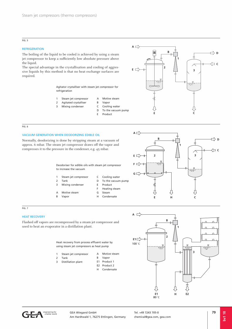
79GEA Wiegand GmbH Tel. +49 7243 705-0
Am Hardtwald 1, 76275 Ettlingen, Germany [email protected], gea.com
bv1
18
Steam jet compressors (thermo compressors)
REFRIGERATION
The boiling of the liquid to be cooled is achieved by using a steam jet compressor to keep a sufficiently low absolute pressure above the liquid.The special advantage in the crystallisation and cooling of aggres-sive liquids by this method is that no heat exchange surfaces are required.
VACUUM GENERATION WHEN DEODORIZING EDIBLE OIL
Normally, deodorizing is done by stripping steam at a vacuum of approx. 6 mbar. The steam jet compressor draws off the vapor and compresses it to the pressure in the condenser, e.g. 45 mbar.
HEAT RECOVERY
Flashed off vapors are recompressed by a steam jet compressor and used to heat an evaporator in a distillation plant.
FIG. 5
FIG. 6
FIG. 7
Deodoriser for edible oils with steam jet compressor
to increase the vacuum
1 Steam jet compressor
2 Tank
3 Mixing condenser
A Motive steam
B Vapor
C Cooling water
D To the vacuum pump
E Product
F Heating steam
G Steam
H Condensate
Agitator crystalliser with steam jet compressor for
refrigeration
1 Steam jet compressor
2 Agitated crystalliser
3 Mixing condenser
A Motive steam
B Vapor
C Cooling water
D To the vacuum pump
E Product
Heat recovery from process effluent water by
using steam jet compressors as heat pump
1 Steam jet compressor
2 Tank
3 Distillation plant
A Motive steam
B Vapor
E1 Product 1
E2 Product 2
H Condensate

80 GEA Wiegand GmbH Tel. +49 7243 705-0
Am Hardtwald 1, 76275 Ettlingen, Germany [email protected], gea.com
Steam jet compressors (thermo compressors)
bv1
18
The motive nozzle connections are not given in the above overview as they depend on the operating conditions.
STANDARD CONSTRUCTION:
Housing: temperature change resistant graphiteMotive nozzle: PTFE/GFKConnection clamps: aluminium castSteam connections: steel galvanized
SPECIAL CONSTRUCTIONS with diff erent connections, nominal pressure stages of the fl ange: materials on request.
For inquiries please use our questionnaire.
FIG. 8
CONNECTIONS, DIMENSIONS AND WEIGHTSSTEAM JET COMPRESSORS,
METAL CONSTRUCTION
FIG. 9
CONNECTIONS, DIMENSIONS AND WEIGHTSSTEAM JET COMPRESSORS,
GRAPHITE CONSTRUCTION
(Replacement for porcelain construction)
DN 25 25 50 50 80 80
I II I II I II
Steam connection DN 25 25 25 25 40 40
Dimensions in mm a 210 300 440 550 750 930
b 30 30 50 50 90 90
c 100 100 110 110 175 175
d 180 270 390 500 660 840
Weight in kg 6 7 18 21 43 46
STANDARD CONSTRUCTIONS:
I Housing: cast iron EN-GJS-400-15 (GGG40), motive nozzle: stainless steel
II Housing: cast stainless steel (1.4581), motive nozzle: stainless steel
DN 25 and 50: housing and diff user screwedDN 80: housing and diff user fl anged, dif-fuser weldedFlanges according to EN1092-1 or ASME 150 lbs
On request the steam jet compressors can be supplied in other sizes, constructions and materials. Connecting fl anges with the requested nominal pressure and according to the required standards can be off ered. The exact installation dimensions of the pumps depend on the operating conditions. Thus, fi g. 8 gives 2 constructions for each diff erent dimension.For large nominal diameters jet pumps are designed in welded construction. The
dimensions are adapted to the particular conditions.The dimensions are given in the quotation on request.
SPECIAL CONSTRUCTIONS and larger nominal diameters on request.Dimensions, connection dimensions and special performance data on request.
For inquiries please use our questionnaire.
DN 32 40 50 65 80 100 125
Dimensions in mm a 320 405 510 653 810 1035 1270
b 90 100 100 130 145 160 170
c 95 110 110 120 135 150 175
d 230 305 410 523 665 875 1100
k 95 120 140 160 185 210 235
D 115 144 164 188 217 242 267
Weight in kg (approx.) 5 8 11 17 21 40 53
(new construction with flanges acc. to EN1092) DN 25 50 80 100
Dimensions in mm a 360 600 985 1320
b 90 100 145 160
c 100 110 135 150
d 270 500 840 1150
Weight in kg (approx.) 5 11 21 40

81GEA Wiegand GmbH Tel. +49 7243 705-0
Am Hardtwald 1, 76275 Ettlingen, Germany [email protected], gea.com
APPLICATIONS
Steam jet ventilators convey air, gases and vapors against small pressure diff erences up to approximately 500 mbar and are used, e.g.:• to draw of waste air, exhaust gases and
vapor• to ventilate tanks• as forced blast blowers, or stack ventila-
tors for boiler burners• to extract and mix exhaust gases from the
thermal afterburning (fi g. 1)
The achievable pressure diff erence between the suction pressure and discharge pressure is the compression of the steam jet ventila-tor.
ADVANTAGES
• no moving parts• maintenance free• can be installed in virtually all situations• quickly and easily put into operation• almost unlimited life, when a suitable
material of construction is chosen• can be manufactured from various
materials of construction• low acquisition costs
Instead of steam, it is also possible to use compressed air or another gas as motive fl uid for jet ventilators. For more detailed information please refer to the section “Gas jet ventilators”, o | gv1.
Apart from steam, air or gas, liquids may be used as the motive medium for jet ventila-tors. For further information please refer to the section “Liquid jet ventilators”, o | fv1.
As opposed to liquid jet ventilators, steam or gas jet ventilators have the advantage that larger pressure differentials can be managed.
Steam jet ventilators operate in a range between Δp = 0 to 500 mbar. Above 500 mbar, steam jet compressors are used (see also section “Steam jet compressors”, o | bv1).
dv1
18
Steam jet ventilators
CONSTRUCTIONS
STEAM JET VENTILATORS ARE AVAILABLE IN TWO DIFFERENT CONSTRUCTIONS:
FIG. 2
Design with axial suction connection
FIG. 3
Design with lateral suction connection
FIG. 1
1, 2 Steam jet ventilators
3 Combustion chamber
A Motive steam
B1, B2 Exhaust gas
E Natural gas
Steam jet ventilators to convey exhaust gases to thermal afterburning
Steam jet ventilator in stainless steel
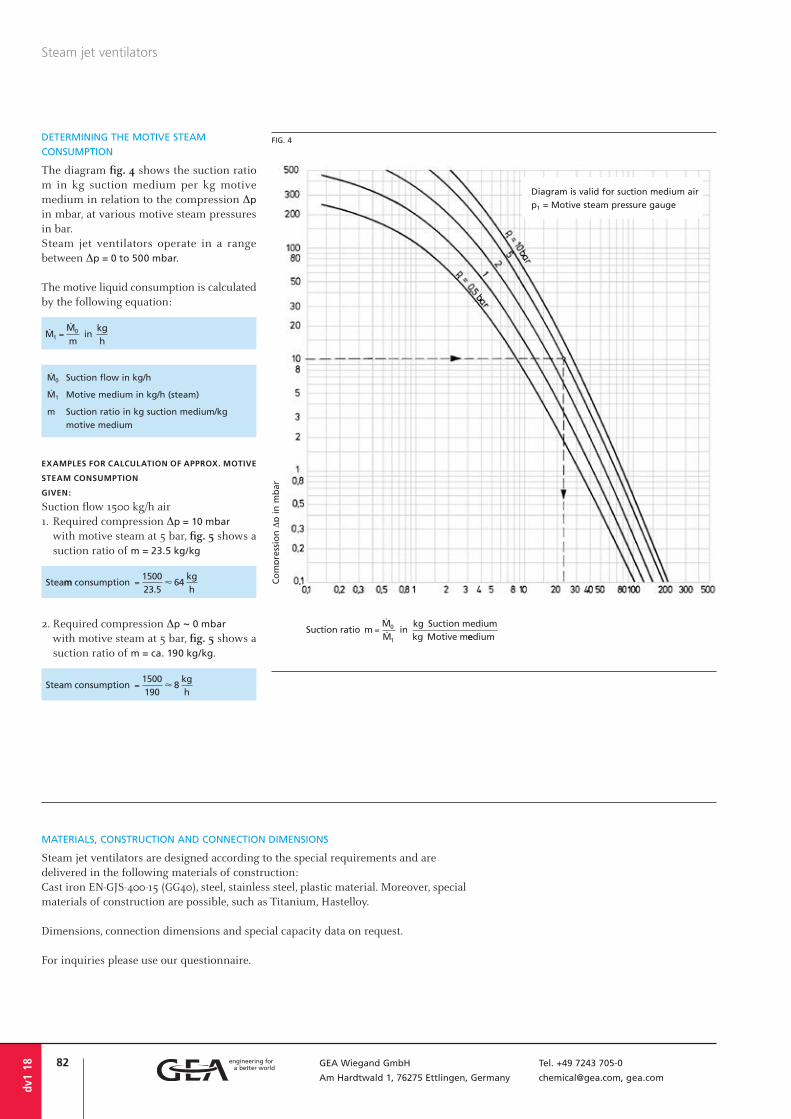
82 GEA Wiegand GmbH Tel. +49 7243 705-0
Am Hardtwald 1, 76275 Ettlingen, Germany [email protected], gea.com
MATERIALS, CONSTRUCTION AND CONNECTION DIMENSIONS
Steam jet ventilators are designed according to the special requirements and are delivered in the following materials of construction:Cast iron EN-GJS-400-15 (GG40), steel, stainless steel, plastic material. Moreover, special materials of construction are possible, such as Titanium, Hastelloy.
Dimensions, connection dimensions and special capacity data on request.
For inquiries please use our questionnaire.
Steam jet ventilators
dv1
18
Co
mp
ress
ion
Δp
in
mb
ar
Diagram is valid for suction medium air
p1 = Motive steam pressure gauge
FIG. 4DETERMINING THE MOTIVE STEAM
CONSUMPTION
The diagram fig. 4 shows the suction ratio m in kg suction medium per kg motive medium in relation to the compression Δp
in mbar, at various motive steam pressures in bar.Steam jet ventilators operate in a range between Δp = 0 to 500 mbar.
The motive liquid consumption is calculated by the following equation:
Ø0 Suction flow in kg/h
Ø1 Motive medium in kg/h (steam)
m Suction ratio in kg suction medium/kg
motive medium
EXAMPLES FOR CALCULATION OF APPROX. MOTIVE
STEAM CONSUMPTION
GIVEN:
Suction flow 1500 kg/h air1. Required compression Δp = 10 mbar
with motive steam at 5 bar, fig. 5 shows a suction ratio of m = 23.5 kg/kg
2. Required compression Δp ~ 0 mbar
with motive steam at 5 bar, fig. 5 shows a suction ratio of m = ca. 190 kg/kg.

83GEA Wiegand GmbH Tel. +49 7243 705-0
Am Hardtwald 1, 76275 Ettlingen, Germany [email protected], gea.com
dv1
18
Questionnairefor steam jet ventilators dv1
Motive medium . . . . . . . . . . . . . . . . . .
Motive pressure . . . . . . . . . . . . . . . . . . bar abs.
Temperature . . . . . . . . . . . . . . . . . . . . . °C
1. MOTIVE SIDE Molecular weight . . . . . . . . . . . . . . . . . kg/kmol
Specific heat capacity . . . . . . . . . . . . . . kJ/kg K
Suction medium . . . . . . . . . . . . . . . . . .
Suction flow . . . . . . . . . . . . . . . . . . . . . kg/h
Suction pressure . . . . . . . . . . . . . . . . . . bar abs.
2. SUCTION SIDE Temperature . . . . . . . . . . . . . . . . . . . . . °C
Molecular weight . . . . . . . . . . . . . . . . . kg/kmol
Specific heat capacity . . . . . . . . . . . . . . kJ/kg K
Required discharge pressure . . . . . . . . . . bar abs.3. OUTLET Mixed flow . . . . . . . . . . . . . . . . . . . . . . kg/h
Additional details, if required, are to be stated separately.
Your inquiry no. . . . . . . . . . . . . . . . . . .
Offer submitted until . . . . . . . . . . . . . . .
Requested date of delivery . . . . . . . . . . .
MATERIAL OF CONSTRUCTION . . . . . . . . . . . . . . . . . . . . . . . . . . . . . . . . . . . . . . . . . . . . . . . . .
CONNECTIONS:
Flanges
Thread
Others
4. FURTHER DATA
DESIGN CODE (if required):
AD-2000
ASME
Others
APPLICATION:
. . . . . . . . . . . . . . . . . . . . . . . . . . . . . .
. . . . . . . . . . . . . . . . . . . . . . . . . . . . . .
. . . . . . . . . . . . . . . . . . . . . . . . . . . . . .
DESIGN:
Temperature . . . . . . . . . . . . . . . . . . . . . °C Pressure . . . . . . . . . . . . . . . . . . . . . . . . bar g
FURTHER NOTES: . . . . . . . . . . . . . . . . . . . . . . . . . . . . . . . . . . . . . . . . . . . . . . . . . . . . . . . . . . .
. . . . . . . . . . . . . . . . . . . . . . . . . . . . . . . . . . . . . . . . . . . . . . . . . . . . . . . . . . . . . . . . . . . . . . .
. . . . . . . . . . . . . . . . . . . . . . . . . . . . . . . . . . . . . . . . . . . . . . . . . . . . . . . . . . . . . . . . . . . . . . .
FLANGES ACCORDING TO:
EN1092-1
ASME lbs
Others
Company . . . . . . . . . . . . . . . . . . . . . . . . . . . . .
attn. . . . . . . . . . . . . . . . . . . . . . . . . . . . . . . . .
Street/P.O. Box . . . . . . . . . . . . . . . . . . . . . . . . .
ZIP code/City . . . . . . . . . . . . . . . . . . . . . . . . . .
Country . . . . . . . . . . . . . . . . . . . . . . . . . . . . . .
YOUR ADDRESS Telephone . . . . . . . . . . . . . . . . . . . . . .
Telefax . . . . . . . . . . . . . . . . . . . . . . . . .
E-mail . . . . . . . . . . . . . . . . . . . . . . . . .
Link to fillable PDF

84 GEA Wiegand GmbH Tel. +49 7243 705-0
Am Hardtwald 1, 76275 Ettlingen, Germany [email protected], gea.com
dv1
18
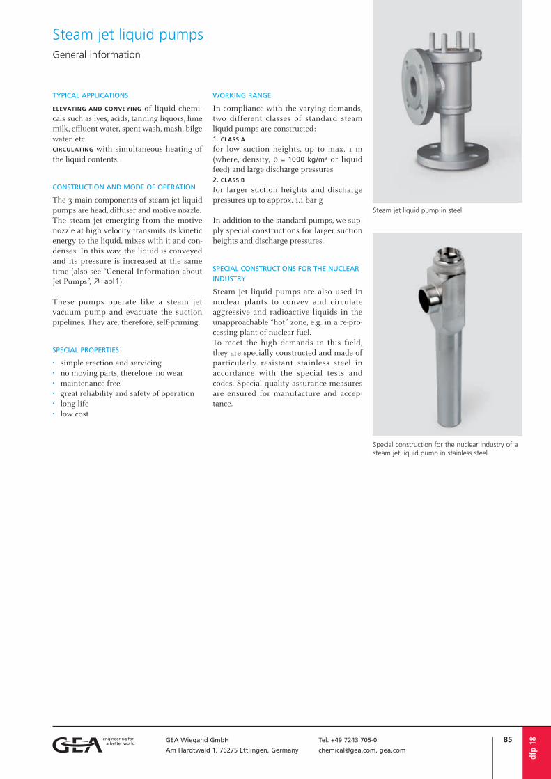
85GEA Wiegand GmbH Tel. +49 7243 705-0
Am Hardtwald 1, 76275 Ettlingen, Germany [email protected], gea.com
TYPICAL APPLICATIONS
ELEVATING AND CONVEYING of liquid chemi-cals such as lyes, acids, tanning liquors, lime milk, effluent water, spent wash, mash, bilge water, etc.CIRCULATING with simultaneous heating of the liquid contents.
CONSTRUCTION AND MODE OF OPERATION
The 3 main components of steam jet liquid pumps are head, diffuser and motive nozzle.The steam jet emerging from the motive nozzle at high velocity transmits its kinetic energy to the liquid, mixes with it and con-denses. In this way, the liquid is conveyed and its pressure is increased at the same time (also see “General Information about Jet Pumps”, o | abl1).
These pumps operate like a steam jet vacuum pump and evacuate the suction pipelines. They are, therefore, self-priming.
SPECIAL PROPERTIES
• simple erection and servicing• no moving parts, therefore, no wear• maintenance-free• great reliability and safety of operation• long life• low cost
WORKING RANGE
In compliance with the varying demands, two different classes of standard steam liquid pumps are constructed:1. CLASS A
for low suction heights, up to max. 1 m (where, density, r = 1000 kg/m³ or liquid feed) and large discharge pressures2. CLASS B
for larger suction heights and discharge pressures up to approx. 1.1 bar g
In addition to the standard pumps, we sup-ply special constructions for larger suction heights and discharge pressures.
SPECIAL CONSTRUCTIONS FOR THE NUCLEAR
INDUSTRY
Steam jet liquid pumps are also used in nuclear plants to convey and circulate aggressive and radioactive liquids in the unapproachable “hot” zone, e.g. in a re-pro-cessing plant of nuclear fuel.To meet the high demands in this field, they are specially constructed and made of particularly resistant stainless steel in accordance with the special tests and codes. Special quality assurance measures are ensured for manufacture and accep-tance.
Steam jet liquid pump in steel
Special construction for the nuclear industry of a steam jet liquid pump in stainless steel
Steam jet liquid pumpsGeneral information
dfp
18

86 GEA Wiegand GmbH Tel. +49 7243 705-0
Am Hardtwald 1, 76275 Ettlingen, Germany [email protected], gea.com
dfp
18
Questionnairefor steam jet liquid pumps dfp1, dfp2
Motive pressure . . . . . . . . . . . . . . . . . . bar abs.1. MOTIVE SIDE Temperature . . . . . . . . . . . . . . . . . . . . . °C
Suction medium . . . . . . . . . . . . . . . . . .
Suction flow . . . . . . . . . . . . . . . . . . . . . m³/h
Delivery head . . . . . . . . . . . . . . . . . . . . m WC
or suction pressure . . . . . . . . . . . . . . . . bar abs.
2. SUCTION SIDE Temperature . . . . . . . . . . . . . . . . . . . . . °C
Density . . . . . . . . . . . . . . . . . . . . . . . . kg/m³
Steam pressure . . . . . . . . . . . . . . . . . . . bar abs.
Required discharge pressure . . . . . . . . . . bar abs.3. OUTLET
MATERIAL OF CONSTRUCTION . . . . . . . . . . . . . . . . . . . . . . . . . . . . . . . . . . . . . . . . . . . . . . . . .
CONNECTIONS:
Flanges
Thread
Others
FLANGES ACCORDING TO:
EN1092-1
ASME lbs
Others
4. FURTHER DATA
DESIGN CODE (if required):
AD-2000
ASME
Others
APPLICATION:
. . . . . . . . . . . . . . . . . . . . . . . . . . . . . .
. . . . . . . . . . . . . . . . . . . . . . . . . . . . . .
. . . . . . . . . . . . . . . . . . . . . . . . . . . . . .
DESIGN:
Temperature . . . . . . . . . . . . . . . . . . . . . °C Pressure . . . . . . . . . . . . . . . . . . . . . . . . bar g
FURTHER NOTES: . . . . . . . . . . . . . . . . . . . . . . . . . . . . . . . . . . . . . . . . . . . . . . . . . . . . . . . . . . .
. . . . . . . . . . . . . . . . . . . . . . . . . . . . . . . . . . . . . . . . . . . . . . . . . . . . . . . . . . . . . . . . . . . . . . .
. . . . . . . . . . . . . . . . . . . . . . . . . . . . . . . . . . . . . . . . . . . . . . . . . . . . . . . . . . . . . . . . . . . . . . .
Additional details, if required, are to be stated separately.
Your inquiry no. . . . . . . . . . . . . . . . . . .
Offer submitted until . . . . . . . . . . . . . .
Requested date of delivery . . . . . . . . . . .
Company . . . . . . . . . . . . . . . . . . . . . . . . . . . . .
attn. . . . . . . . . . . . . . . . . . . . . . . . . . . . . . . . .
Street/P.O. Box . . . . . . . . . . . . . . . . . . . . . . . . .
ZIP code/City . . . . . . . . . . . . . . . . . . . . . . . . . .
Country . . . . . . . . . . . . . . . . . . . . . . . . . . . . . .
YOUR ADDRESS Telephone . . . . . . . . . . . . . . . . . . . . . .
Telefax . . . . . . . . . . . . . . . . . . . . . . . . .
E-mail . . . . . . . . . . . . . . . . . . . . . . . . .
Link to fillable PDF

87GEA Wiegand GmbH Tel. +49 7243 705-0
Am Hardtwald 1, 76275 Ettlingen, Germany [email protected], gea.com
PERFORMANCE CHART
Steam jet liquid pumps class A are suitable for low suction heights, up to max. 1 m(where, density, r = 1000 kg/m³ or for liquid feed) and large discharge pressure.
EXAMPLE
6 m³/h of water is to be drawn at a suction height of 1 m and conveyed to a discharge pressure of 1.6 bar g. A motive steam pressure of 3 bar g is avail-able.PARAMETERS TO BE FOUND: Pump size and motive steam consumption. SOLUTION: The diagram fig. 1 shows that for a discharge pressure of 1.6 bar g and a motive steam pressure of 3 bar g in relation to the delivery of 6 m³/h, a pump size 5 has to be used.
Fig. 2 shows a steam consumption of approx. 190 kg/h for the chosen size.
Steam jet liquid pumps Class A
dfp1
18
Discharge pressure in bar gSize
Del
iver
y in
m3 /
h
p1 = Motive steam pressure gauge
Delivery in m³/h of water at a suction height of approximately 1 m in relation to the discharge pressure at varying motive steam pressures p1. Size 1 achieves only 65-70 % of the given discharge pressures.
FIG. 1
Motive steam pressure in bar gSize
Stea
m c
on
sum
pti
on
in
kg
/h
Steam consumption in kg/h of the individual sizes in relation to the motive steam pressure.
FIG. 2
Water temperature in °C
Suct
ion
cap
acit
y in
%
The drop in % of the delivery with increasing water temperature
FIG. 3The liquid to be conveyed must not be too hot, so that the motive steam condenses in it and the total energy is available to convey the liquid (see diagram fig. 3).It must be taken into consideration that not only higher temperatures, but also higher specific gravities of the liquid to be conveyed reduce the performance of the pumps.
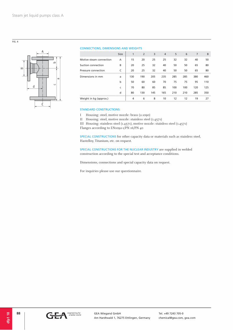
88 GEA Wiegand GmbH Tel. +49 7243 705-0
Am Hardtwald 1, 76275 Ettlingen, Germany [email protected], gea.com
CONNECTIONS, DIMENSIONS AND WEIGHTS
Steam jet liquid pumps class A
dfp1
18
Size 1 2 3 4 5 6 7 8
Motive steam connection A 15 20 25 25 32 32 40 50
Suction connection B 20 25 32 40 50 50 65 80
Pressure connection C 20 25 32 40 50 50 65 80
Dimensions in mm a 130 190 205 235 285 285 380 460
b 50 60 60 70 75 75 95 110
c 70 80 85 85 100 100 120 125
d 80 130 145 165 210 210 285 350
Weight in kg (approx.) 4 6 8 10 12 12 19 27
STANDARD CONSTRUCTIONS:
I Housing: steel, motive nozzle: brass (2.1090)II Housing: steel, motive nozzle: stainless steel (1.4571)III Housing: stainless steel (1.4571), motive nozzle: stainless steel (1.4571)Flanges according to EN1092-1/PN 16/PN 40
SPECIAL CONSTRUCTIONS for other capacity data or materials such as stainless steel, Hastelloy, Titanium, etc. on request.
SPECIAL CONSTRUCTIONS FOR THE NUCLEAR INDUSTRY are supplied in welded construction according to the special test and acceptance conditions.
Dimensions, connections and special capacity data on request.
For inquiries please use our questionnaire.
FIG. 4

89GEA Wiegand GmbH Tel. +49 7243 705-0
Am Hardtwald 1, 76275 Ettlingen, Germany [email protected], gea.com
PERFORMANCE CHART
Steam jet liquid pumps class B are constructed for suction heights larger than 1 m and dis-charge pressure up to approximately 1.1 bar g.
EXAMPLE
5 m³/h of water is to be drawn from a mano-metric suction pressure of –0.6 bar and con-veyed to a discharge pressure of 0.45 bar g.
PARAMETERS TO BE FOUND: Pump size, motive steam pressure and consumption requiredSOLUTION: The delivery and the suction pres-sure determine the size of the pump whilst the discharge pressure determines the motive steam pressure required.The example in fig. 5 gives a size 4 pump and a motive steam pressure of 4 bar.
The steam consumption of 110 kg/h is found in diagram fig. 6.
Steam jet liquid pumps operate like a steam jet vacuum pump and evacuate the suction pipelines (in start-up). They are, therefore, self-priming.It must each time be checked by means of fig. 7 whether at the motive steam pres-sure determined according to fig. 5 the maximum suction pressure (blind vacuum) is lower than the necessary manometric suction pressure.
dfp2
18
Steam jet liquid pumps Class B
p1 = Motive steam pressure gauge
Pressures in bar correspond to gauge
Max. discharge pressure plimit in bar (g)Manometric suction
pressure p0 in bar
Size
Del
iver
y in
m3 /
h
Delivery in m³/h of water at a temperature of 20 °C, depending on the suction and discharge pressure (limit discharge pressure) at different motive steam pressures p1
FIG. 5
Size Motive steam pressure in bar g
Stea
m c
on
sum
pti
on
in
kg
/h
FIG. 6
Steam consumption in kg/h of the individual sizes in relation to the motive steam pressure
Max. suction pressure (blind
vacuum) in bar abs. to be reached
Mo
tive
ste
am p
ress
ure
in
bar
g
FIG. 7
Suction behaviour (blind vacuum) of steam jet liquid pumps class B

90 GEA Wiegand GmbH Tel. +49 7243 705-0
Am Hardtwald 1, 76275 Ettlingen, Germany [email protected], gea.com
CONNECTIONS, DIMENSIONS AND WEIGHTS
The liquid to be conveyed must not be too hot, because only if the motive steam con-denses and thereby loses its volume, can the total energy available to convey the liquid become fully eff ective (see diagram fi g. 8).
With lower suction height or liquid feed, liquids with temperature up to 90 °C can be conveyed.
The theoretical suction pressure shown in fi g. 9 with the broken line, for the same delivery, changes from –0.7 bar at 20 °C to –0.4 bar at 60 °C.
dfp2
18
Steam jet liquid pumps class B
Size 1 2 3 4 5 6 7 8
Motive steam connection A 15 20 25 25 32 32 40 50
Suction connection B 20 25 32 40 50 50 65 80
Pressure connection C 20 25 32 40 50 50 65 80
Dimensions in mm a 130 190 205 235 285 285 380 460
b 50 60 60 70 75 75 95 110
c 70 80 85 85 100 100 120 125
d 80 130 145 165 210 210 285 350
Weight in kg (approx.) 4 6 8 10 12 12 19 27
STANDARD CONSTRUCTIONS:
I Housing: steel, motive nozzle: brass (2.1090)II Housing: steel, motive nozzle: stainless steel (1.4571)III Housing: stainless steel (1.4571), motive nozzle: stainless steel (1.4571)Flanges according to EN1092-1/PN 16/PN 40
SPECIAL CONSTRUCTIONS for other performance data or materials, such as for example stainless steel, Hastelloy, Titanium, etc. on request.
SPECIAL CONSTRUCTIONS FOR THE NUCLEAR INDUSTRY are supplied in welded construction according to the special test and acceptance conditions.
Dimensions, connections and special capacity data on request.
For inquiries please use our questionnaire.
Deficiency in output in %
Wat
er t
emp
erat
ure
in
°C
FIG. 8
Infl uence of the water temperature on the delivery at a constant geodetic suction height of 5 m and a constant motive steam overpressure of 5 bar.
Suction pressure p0 in bar g
Wat
er t
emp
erat
ure
in
°C
FIG. 9
Relation between the theoretical suction pressure (manometric suction height) and the water temperature.
FIG. 10

91GEA Wiegand GmbH Tel. +49 7243 705-0
Am Hardtwald 1, 76275 Ettlingen, Germany [email protected], gea.com
Steam jet heater for vessels with flanged connection, type 18.1 in cast iron
Steam jet heater for vessels with threaded connection, type 18.1 in cast stainless steel
Steam jet heaters are used to heat liquids by direct injection of heating steam. The heat-ing steam condensate mixes with the liquid being heated.Steam jet heaters are used to prepare hot water for different purposes, such as barrel rinsing water in malting plants, warm water for pickling, dyeing, and greases in tan-neries, for washrooms and bathrooms and for heating sewage sludge, boiling lyes etc.
SPECIAL FEATURES
• low noise operation• simple construction• no moving parts• low maintenance• high reliability• adjustable heating capacity
CONSTRUCTION FORMS
There are generally 2 different construction forms, according to the application• steam jet heaters for vessels• steam jet heaters for installation in pipes
and for passage and circulation heatingsystems: Type “L”, Type “H”, “System Ciba-Geigy”
Steam jet heatersGeneral information
aw
18
Steam jet heater “System Ciba-Geigy” in stainless steel
Steam jet heater “System Ciba-Geigy” in cast iron
Steam jet heater, type “H” in stainless steel
Steam jet heater, type “L” in stainless steel
Steam jet heater, type “H” in steel
Steam jet heater, type “L” in steel

92 GEA Wiegand GmbH Tel. +49 7243 705-0
Am Hardtwald 1, 76275 Ettlingen, Germany [email protected], gea.com
aw1
18
Questionnairefor steam jet heaters for vessels aw1
Volume of the tank or basin . . . . . . . . . . m³
Diameter . . . . . . . . . . . . . . . . . . . . . . . mm
Length . . . . . . . . . . . . . . . . . . . . . . . . . mm
1. DIMENSIONS OF THE TANK OR BASIN
Width . . . . . . . . . . . . . . . . . . . . . . . . . mm
Height . . . . . . . . . . . . . . . . . . . . . . . . . mm
2. REQUIREMENTS ON THE HEATING
Heating capacity . . . . . . . . . . . . . . . . . . kW
Heating steam pressure . . . . . . . . . . . . . bar abs.
Heating steam temperature . . . . . . . . . . °C
Heating time . . . . . . . . . . . . . . . . . . . . h
Initial temperature . . . . . . . . . . . . . . . . °C
Final temperature . . . . . . . . . . . . . . . . . °C
FURTHER REQUIREMENTS: . . . . . . . . . . . . . . . . . . . . . . . . . . . . . . . . . . . . . . . . . . . . . . . . . . . .
. . . . . . . . . . . . . . . . . . . . . . . . . . . . . . . . . . . . . . . . . . . . . . . . . . . . . . . . . . . . . . . . . . . . . . .
. . . . . . . . . . . . . . . . . . . . . . . . . . . . . . . . . . . . . . . . . . . . . . . . . . . . . . . . . . . . . . . . . . . . . . .
MEDIUM TO BE HEATED:
Specific heat capacity . . . . . . . . . . . . . . kJ/kg K
Vapor pressure at final temperature . . . . . . . . . . . . . . . . . . . . . . . . . . . . . . . . . . . . . . . . . . . . . bar abs.
Dyn. viscosity . . . . . . . . . . . . . . . . . . . . mPas
Density . . . . . . . . . . . . . . . . . . . . . . . . kg/m3
3. FURTHER DATA MATERIAL OF CONSTRUCTION . . . . . . . . . . . . . . . . . . . . . . . . . . . . . . . . . . . . . . . . . . . . . . . . . .
Installation according to catalog sheet aw1 Fig. 2 Fig. 4
CONNECTIONS:
Flanges
Thread
Others
FURTHER NOTES: . . . . . . . . . . . . . . . . . . . . . . . . . . . . . . . . . . . . . . . . . . . . . . . . . . . . . . . . . . .
. . . . . . . . . . . . . . . . . . . . . . . . . . . . . . . . . . . . . . . . . . . . . . . . . . . . . . . . . . . . . . . . . . . . . . .
. . . . . . . . . . . . . . . . . . . . . . . . . . . . . . . . . . . . . . . . . . . . . . . . . . . . . . . . . . . . . . . . . . . . . . .
FLANGES ACCORDING TO:
EN1092-1
ASME lbs
Others
Additional details, if required, are to be stated separately.
Your inquiry no. . . . . . . . . . . . . . . . . . .
Offer submitted until . . . . . . . . . . . . . .
Requested date of delivery . . . . . . . . . . .
Company . . . . . . . . . . . . . . . . . . . . . . . . . . . . .
attn. . . . . . . . . . . . . . . . . . . . . . . . . . . . . . . . .
Street/P.O. Box . . . . . . . . . . . . . . . . . . . . . . . . .
ZIP code/City . . . . . . . . . . . . . . . . . . . . . . . . . .
Country . . . . . . . . . . . . . . . . . . . . . . . . . . . . . .
YOUR ADDRESS Telephone . . . . . . . . . . . . . . . . . . . . . .
Telefax . . . . . . . . . . . . . . . . . . . . . . . . .
E-mail . . . . . . . . . . . . . . . . . . . . . . . . .
Link to fillable PDF

93GEA Wiegand GmbH Tel. +49 7243 705-0
Am Hardtwald 1, 76275 Ettlingen, Germany [email protected], gea.com
aw1
18
APPLICATION
Steam jet heaters are used to heat all kinds of liquids in vessels. Heating is achieved by means of direct condensation of steam. The steam condensate mixes with the liquid.
MODE OF OPERATION
The steam jet emerging from the motive nozzle accelerates the liquid present in its vicinity and in the mixing nozzle, and con-denses (see also “General information on jet pumps”, o | abl1).In this way a controlled flow is produced. Furthermore, the whole content of the ves-sel is set in motion and the heat transferred to the liquid is evenly distributed through-out the vessel.All the heaters are provided with a threaded connection for an air pipe. Normally it is not necessary to operate with air supply. How-ever, the admission of air greatly intensifies the movement of the circulating liquid; it can also assists in avoiding condensation hammers and rattling that may occur when starting with a cold liquid. If air is to be supplied, a corresponding line with installed regulation valve has to be con-nected (see fig. 2, 4, 6). Depending on the application, atmospheric air which is sucked in by the heater itself is sufficient.
Steam jet heaters for vessels
Steam jet heater type 18.1, with thread
Steam jet heater type 28.1, with flange
To operate the steam jet heater, a steam overpressure of at least 1.5 bar is necessary to overcome the static pressure of the liquid and to achieve the minimum speed at which no disturbing noise is produced.The heaters described can also be used for operating with low pressure steam (special construction).
PERFORMANCE CHART
On the bottom scale, the chart in fig. 1 gives the heat flow in kW for each size. This is the heat content of the inflowing steam. How-ever, the heat actually transferred to the liquid is less. It is reduced by the heat con-tained in the condensate.The condensate flow produced by the con-densation of the inflowing steam is given on the top scale. With the aid of this scale and the temperature J of the heated liquid, the heat flow actually transferred is calculated as follows:
Whereas:
œtr Transferred heat flow in kW
œ Heat flow in kW = Enthalpy of the
inflowing steam
ØC Condensate flow in kg/h
c Specific heat capacity of the condensate
in kJ/kg °C (water = 4.2)
J Temperature of the heated water in °C
EXAMPLE
GIVEN: A steam quantity of approx. 70 kg/h is required to heat a vessel. Steam at 2 bar g is available.SOLUTION: The chart in fig. 1 shows that size 1-80 matches the example.
Performance chart for steam jet heaters, size 1 to 7, construction series 80, for water
FIG. 1
Stea
m p
ress
ure
in
bar
g
Heat flow œ in kW ¥ Enthalpy of the inflowing steam
Steam consumption ØD or condensate ØC in kg/h or kg/s resp.
Steam jet heaters,
sizes 1–7,series 80
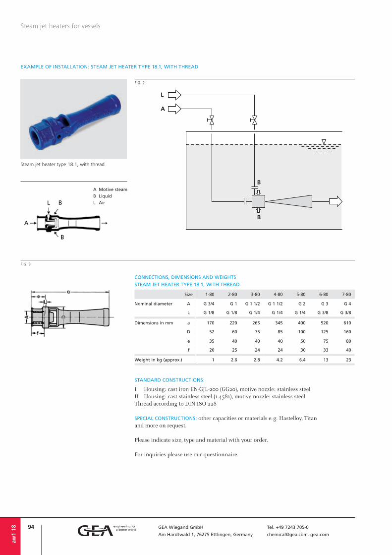
94 GEA Wiegand GmbH Tel. +49 7243 705-0
Am Hardtwald 1, 76275 Ettlingen, Germany [email protected], gea.com
aw1
18
Steam jet heaters for vessels
EXAMPLE OF INSTALLATION: STEAM JET HEATER TYPE 18.1, WITH THREAD
FIG. 2
Size 1-80 2-80 3-80 4-80 5-80 6-80 7-80
Nominal diameter A G 3/4 G 1 G 1 1/2 G 1 1/2 G 2 G 3 G 4
L G 1/8 G 1/8 G 1/4 G 1/4 G 1/4 G 3/8 G 3/8
Dimensions in mm a 170 220 265 345 400 520 610
D 52 60 75 85 100 125 160
e 35 40 40 40 50 75 80
f 20 25 24 24 30 33 40
Weight in kg (approx.) 1 2.6 2.8 4.2 6.4 13 23
CONNECTIONS, DIMENSIONS AND WEIGHTS
STEAM JET HEATER TYPE 18.1, WITH THREAD
STANDARD CONSTRUCTIONS:
I Housing: cast iron EN-GJL-200 (GG20), motive nozzle: stainless steelII Housing: cast stainless steel (1.4581), motive nozzle: stainless steelThread according to DIN ISO 228
SPECIAL CONSTRUCTIONS: other capacities or materials e. g. Hastelloy, Titan and more on request.
Please indicate size, type and material with your order.
For inquiries please use our questionnaire.
FIG. 3
Steam jet heater type 18.1, with thread
A Motive steam
B Liquid
L Air

95GEA Wiegand GmbH Tel. +49 7243 705-0
Am Hardtwald 1, 76275 Ettlingen, Germany [email protected], gea.com
aw1
18
Steam jet heaters for vessels
Size 1-80 2-80 3-80 4-80 5-80 6-80 7-80
Nominal diameter A 20 25 40 40 50 80 100
L G 1/8 G 1/8 G 1/4 G 1/4 G 1/4 G 3/8 G 3/8
Dimensions in mm a 205 255 300 380 440 570 665
e 70 75 75 75 90 125 135
Weight in kg (approx.) 2.2 3 5.2 6.6 9.3 18 30
A Motive steam
B Liquid
L Air
EXAMPLE OF INSTALLATION: STEAM JET HEATER TYPE 28.1, WITH FLANGE
FIG. 4
CONNECTIONS, DIMENSIONS AND WEIGHTS
STEAM JET HEATER TYPE 28.1, WITH FLANGE
STANDARD CONSTRUCTIONS:
I Housing: cast iron EN-GJL-200 (GG20), motive nozzle: stainless steelII Housing: cast stainless steel (1.4581), motive nozzle: stainless steelFlanges according to EN1092-1 PN 16Threads according to DIN ISO 228
SPECIAL CONSTRUCTIONS: other capacities or materials e. g. Hastelloy, Titan and more on request.
Please indicate size, type and material with your order.
For inquiries please use our questionnaire.
FIG. 5
Steam jet heater type 28.1, with flange

96 GEA Wiegand GmbH Tel. +49 7243 705-0
Am Hardtwald 1, 76275 Ettlingen, Germany [email protected], gea.com
aw1
18
Steam jet heaters for vessels
EXAMPLE OF INSTALLATION: STEAM JET HEATER WITH HOUSING, TYPE 38.1
SPECIAL CONSTRUCTIONS DESIGNED ACCORDING TO THE CUSTOMER’S SPECIFICATION
Steam jet heaters, type 38.1 must only be used for a liquid level of min. 0.5 m above the heater.
Dimensions, connection dimensions, mate-rials and special capacity data on request.
A Motive steam
B Liquid
L Air
FIG. 6

97GEA Wiegand GmbH Tel. +49 7243 705-0
Am Hardtwald 1, 76275 Ettlingen, Germany [email protected], gea.com
MODE OF OPERATION
The condensation nozzle is inside the steam jet heater. It is provided with bore holes so that the steam can pass directly into the liq-uid to be heated and condenses (fig. 7). This takes place at the point of highest velocity of the liquid, its lowest pressure and its great-est turbulence.The downstream arranged diffuser reduces the velocity of the liquid again at the same time increasing its pressure. The heaters can be installed in any position. The steam valve shall be installed directly at the steam connection, if possible. A straight smoothing and slowing-down section of at least 10 x DN is to be provided for down-stream of the heater.The heaters perform a noiseless operation and can be designed even for exhaust steam. Under defined conditions, the liquid to be heated flows through the heater without pressure loss; with sufficiently high steam pressure, a pressure boost is achieved.Fig. 8 shows the max. permissible discharge pressure p in relation to pF and pD; in start-up mode, i.e. without steam, the discharge pressure p is allowed to be max. 60 % of the water inlet pressure pF.
aw4
18
Steam jet heater type “L”
APPLICATION
Steam jet heaters are used to heat liquids by means of direct condensation of steam. The steam condensate mixes with the liquid.Steam jet heaters, type “L” are used in pas-sage and circulation heating systems.The achievable heating per pass amounts to max. 90 K.
Steam jet heaters “L” for installation in pipelines
FIG. 9
Dis
char
ge
pre
ssu
re p
in
bar
Inlet pressure pF in bar
FIG. 8
FIG. 7
1 Housing
2 Condensation nozzle
3 Diffuser
pF Liquid inlet pressure
pD Steam pressure
p Discharge pressure
A, C Liquid
B Steam
ΔJ = Temperature difference
pF = Liquid inlet pressure
Heating steam pressure pD in bar
Wat
er f
low
to
be
hea
ted
in
m3 /
h
Size
lower limit
The performance chart fig. 9 shows to which temperature a liquid can be heated, depending on the liquid flow and on the steam pressure at an inlet temperature of 20 °C

98 GEA Wiegand GmbH Tel. +49 7243 705-0
Am Hardtwald 1, 76275 Ettlingen, Germany [email protected], gea.com
CONNECTIONS, DIMENSIONS AND WEIGHTS
Steam jet heaters “L” for installation in pipelines
aw4
18
STANDARD CONSTRUCTIONS:
I Housing: steel, condensation nozzle: red brassII Housing: steel, condensation nozzle: stainless steel (1.4571)III Housing: stainless steel (1.4571), condensation nozzle: stainless steel (1.4571)Flanges: EN1092-1 PN 16
SPECIAL CONSTRUCTIONS: other capacities or materials e. g. Hastelloy, Titan and more on request.
For inquiries please use our questionnaire.
Size 0 1 2 3 4 5 6 7 8 9 10
Nominal A 25 32 40 50 65 65 80 100 125 150 150
diameter B 32 40 50 65 80 100 125 150 200 200 250
C 25 32 40 50 65 65 80 100 125 150 150
Dimensions a 230 265 310 350 380 425 650 890 975 1275 1275
in mm b 70 85 100 110 125 140 200 345 365 515 515
c 85 100 105 120 130 140 175 200 200 200 200
d 160 180 210 240 255 285 450 545 610 760 760
Weight in kg (approx.) 7 9 12 15 21 23 34 51 60 72 90
FIG. 12
Flo
w r
ate
in %
Water inlet temperature in °C
Infl uence of the liquid inlet temperature on the liquid fl ow rate
Size 0 1 2 3 4 5 6 7 8 9 10
Factor 1 1.67 3 4.6 6.75 8.6 16 23 32 49 67
Stea
m p
ress
ure
pD i
n b
ar
Steam consumption of size 0 in kg/h
Steam consumption of size 0 in function of the steam pressure
EXAMPLE
40 m³/h water is to be heated from 10 °C to 40 °C with steam between 1-2 bar.PARAMETERS TO BE FOUND: Size of the heater and steam consumption.DETERMINATION OF THE SIZE: Diagram fi g. 10 shows that the liquid fl ow rate at an inlet temperature of 10 °C = 110 %. This means that the determination of the size and of the water inlet pressure has to be based only on 36.5 m³/h instead of 40 m³/h. Thus, size 6 as well as size 7 are to be found for this in dia-gram fi g. 9.Water inlet pressure at size 6: 3.0 bar at size 7: 0.8 barDETERMINATION OF THE STEAM CONSUMPTION:
According to fi g. 11, the steam consump-tion at a steam pressure of 1.4 bar and size 0 amounts to approx. 80 kg/h.In order to determine the steam consump-tion of another size, the steam consumption of size 0 is multiplied by the factor of the size to be found.
According to the table, the factor for size 7 is 23. Thus, the steam consumption for size 7 is resulting with: 80 x 23 ≈ 1840 kg/h.
FIG. 11FIG. 10
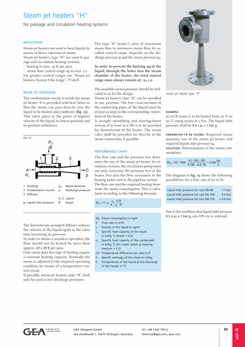
99GEA Wiegand GmbH Tel. +49 7243 705-0
Am Hardtwald 1, 76275 Ettlingen, Germany [email protected], gea.com
aw5
18
The type “H” heater’s ratio of maximum steam flow to minimum steam flow, its so-called control range, depends on the dis-charge pressure p and the steam pressure pD.
In order to prevent the backing up of the liquid, through the holes into the steam chamber of the heater, the total control range must always remain at: pD ≥ p
The available steam pressure should be indi-cated to us for the design.Steam jet heaters type “H” can be installed in any position. The free cross-sections of the connecting pipes of the liquid must be at least as large as the corresponding connec-tions of the heater.A straight smoothing and slowing-down section of at least 10 x DN is to be provided for downstream of the heater. The steam valve shall be provided for directly at the steam connection, if possible.
PERFORMANCE CHART
The flow rate and the pressure loss deter-mine the size of the steam jet heater. In cir-culation systems, the circulation pump must not only overcome the pressure loss of the heater, but also the flow resistance in the heating jacket and in the pipeline system.The flow rate and the required heating de ter - mine the steam consumption. This is calcu-lated according to the following formula:
APPLICATION
Steam jet heaters are used to heat liquids by means of direct injection of steam.Steam jet heaters, type “H”, are used in pas-sage and circulation heating systems.• heating to max. 30 K per pass• steam flow control range up to max. 5:1For greater control ranges see “Steam jetheaters, System Ciba Geigy”, o | aw6.
MODE OF OPERATION
The condensation nozzle is inside the steam jet heater. It is provided with bore holes so that the steam can pass directly into the liquid to be heated and condenses (fig. 13).This takes place at the point of highest velocity of the liquid, its lowest pressure and its greatest turbulence.
The downstream arranged diffuser reduces the velocity of the liquid again at the same time increasing its pressure.In order to obtain a noiseless operation, the flow should not be heated by more than approx. ΔJ = 30 K per pass.Only rarely does this type of heating require a constant heating capacity. Normally the steam is adjusted to the required operating condition by means of a temperature con-trol circuit.If possible, steam jet heaters, type “H”, shall only be used at low discharge pressures.
Steam jet heater type “H”
Steam jet heaters “H”for passage and circulation heating systems
FIG. 13
1 Housing
2 Condensation nozzle
3 Diffuser
pF Liquid inlet pressure
pD Steam pressure
p Discharge pressure
A, C Liquid
B Steam
EXAMPLE
50 m³/h water is to be heated from 20 °C to 50 °C using steam at 3 bar. The liquid inlet pressure shall be 0.5 ≤ pF ≤ 1 bar g.
PARAMETER TO BE FOUND: Required steam quantity, size of the steam jet heater and required liquid inlet pressure pF.SOLUTION: Determination of the steam con-sumption:
The diagram in fig. 15 shows the following possibilities for a flow rate of 50 m³/h:
Liquid inlet pressure for size DN 80: 1.1 bar
Liquid inlet pressure for size DN 100: 0.5 bar
Liquid inlet pressure for size DN 125: < 0.4 bar
Due to the condition that liquid inlet pressure 0.5 ≤ pF ≤ 1 bar g, size DN 100 is selected.
ØD Steam consumption in kg/h
å Flow rate in m³/h
r Density of the liquid in kg/m³
cL Specific heat capacity of the liquid
in kJ/kg °C (water = 4.2)
cC Specific heat capacity of the condensate
in kJ/kg °C (for water steam as heating
medium = 4.2)
ΔJ Temperature difference per pass in K
h Specific enthalpy of the steam in kJ/kg
J Temperature of the liquid at the discharge
of the heater in °C
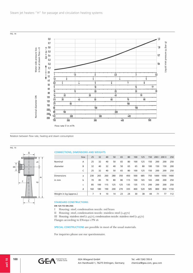
100 GEA Wiegand GmbH Tel. +49 7243 705-0
Am Hardtwald 1, 76275 Ettlingen, Germany [email protected], gea.com
Steam jet heaters “H” for passage and circulation heating systems
aw5
18
FIG. 14
Flow rate å in m3/h
Liq
uid
in
let
pre
ssu
re p
F (b
ar g
)
Wat
er-s
ide
pre
ssu
re l
oss
in b
ar a
t st
eam
flo
w =
0
No
min
al d
iam
eter
DN
Relation between fl ow rate, heating and steam consumption
STANDARD CONSTRUCTIONS:
DN 125 TO DN 250:
I Housing: steel, condensation nozzle: red brassII Housing: steel, condensation nozzle: stainless steel (1.4571)III Housing: stainless steel (1.4571), condensation nozzle: stainless steel (1.4571)Flanges according to EN1092-1 PN 16
SPECIAL CONSTRUCTIONS are possible in most of the usual materials.
For inquiries please use our questionnaire.
Size 25 32 40 50 65 80 100 125 150 200 I 200 II 250
Nominal A 25 32 40 50 65 80 100 125 150 200 200 250
diameter B 32 40 32 40 50 65 65 80 100 150 150 200
C 25 32 40 50 65 80 100 125 150 200 200 250
Dimensions a 230 265 260 280 350 450 500 685 750 1000 1050 1400
in mm b 70 85 70 80 80 115 100 165 165 200 200 250
c 85 100 115 125 125 135 135 175 200 200 200 250
d 160 180 190 200 270 335 400 520 585 800 850 1150
Weight in kg (approx.) 7 9 10 14 23 24 30 38 44 71 77 112
FIG. 15
CONNECTIONS, DIMENSIONS AND WEIGHTS
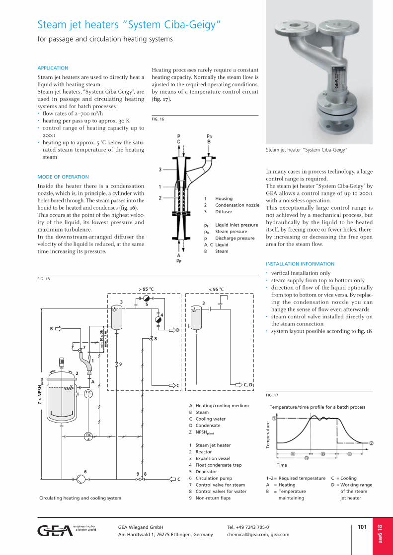
101GEA Wiegand GmbH Tel. +49 7243 705-0
Am Hardtwald 1, 76275 Ettlingen, Germany [email protected], gea.com
pD
aw6
18
APPLICATION
Steam jet heaters are used to directly heat a liquid with heating steam.Steam jet heaters, “System Ciba Geigy”, are used in passage and circulating heating systems and for batch processes:• flow rates of 2–700 m³/h• heating per pass up to approx. 30 K• control range of heating capacity up to
200:1• heating up to approx. 5 °C below the satu-
rated steam temperature of the heatingsteam
MODE OF OPERATION
Inside the heater there is a condensation nozzle, which is, in principle, a cylinder with holes bored through. The steam passes into the liquid to be heated and condenses (fig. 16).This occurs at the point of the highest veloc-ity of the liquid, its lowest pressure and maximum turbulence.In the downstream-arranged diffuser the velocity of the liquid is reduced, at the same time increasing its pressure.
Heating processes rarely require a constant heating capacity. Normally the steam flow is ajusted to the required operating con ditions, by means of a temperature control circuit (fig. 17).
In many cases in process technology, a large control range is required.The steam jet heater “System Ciba-Geigy” by GEA allows a control range of up to 200:1 with a noiseless operation.This exceptionally large control range is not achieved by a mechanical process, but hydraulically by the liquid to be heated itself, by freeing more or fewer holes, there-by increasing or decreasing the free open area for the steam flow.
INSTALLATION INFORMATION
• vertical installation only• steam supply from top to bottom only• direction of flow of the liquid optionally
from top to bottom or vice versa. By replac -ing the condensation nozzle you canhange the sense of flow even afterwards
• steam control valve installed directly onthe steam connection
• system layout possible according to fig. 18
Steam jet heater “System Ciba-Geigy”
Steam jet heaters “System Ciba-Geigy”for passage and circulation heating systems
1 Housing
2 Condensation nozzle
3 Diffuser
pF Liquid inlet pressure
pD Steam pressure
p Discharge pressure
A, C Liquid
B Steam
FIG. 16
FIG. 18
Circulating heating and cooling system
Temperature / time profile for a batch process
Tem
per
atu
re
Time
FIG. 17
1–2 = Required temperature
A = Heating
B = Temperature
maintaining
C = Cooling
D = Working range
of the steam
jet heater
A Heating / cooling medium
B Steam
C Cooling water
D Condensate
Z NPSHplant
1 Steam jet heater
2 Reactor
3 Expansion vessel
4 Float condensate trap
5 Deaerator
6 Circulation pump
7 Control valve for steam
8 Control valves for water
9 Non-return flaps

102 GEA Wiegand GmbH Tel. +49 7243 705-0
Am Hardtwald 1, 76275 Ettlingen, Germany [email protected], gea.com
aw6
18
Steam jet heaters “System Ciba-Geigy” for passage and circulation heating systems
Flow rate å in m3/h
Liq
uid
in
let
pre
ssu
re p
F (b
ar g
)
Wat
er-s
ide
pre
ssu
re l
oss
Δp
(b
ar)
at s
team
flo
w =
0
No
min
al d
iam
eter
DN
FIG. 19 PERFORMANCE CHART
The flow rate and the pressure loss deter-mine the size of the steam jet heater. In fig. 19, the pressure loss at steam flow = 0 is in relation to the circulated flow rate. At temperature differences greater than 10 °C between inlet and outlet, the pressure loss will reduce due to the conveying effect of the steam. This has the advantage that, dur-ing the heating phase the circulation pump is relieved, the circulated flow rises and a better heat transfer is achieved. The flow rate and the required heating determine the steam flow. This is calculated according to the following formula:
ØD Steam consumption in kg/h
å Flow rate in m³/h
r Density of the liquid in kg/m³
cL Special heat capacity of the liquid
in kJ/kg °C (water = 4.2)
cC Special heat capacity of the condensate
in kJ/kg °C (for water steam as heating
medium= 4.2)
ΔJ Temperature difference per pass in K
h Special enthalpy of the steam in kJ/kg
J Temperature of the liquid at the outlet
of the heater in °C
EXAMPLE
A circulating flow of 50 m³/h is to be heat-ed from 40 °C to 80 °C by means of steam at 3 bar. The heating per pass is to amount to 20 K.PARAMETERS TO BE FOUND: Required steam flow, size of the steam jet heater and liquid inlet pressure.SOLUTION: Determination of the steam con-sumption:
The diagram, fig. 20, shows a steam jet heat-er DN 100 for a circulating flow of 50 m³/h.The required liquid inlet pressure amounts to 0.7 bar g.
FIG. 20
Size 40 I 40 II 50 65 80 100 125 150 200
Nominal A 40 40 50 65 80 100 125 150 200
diameter B 40 40 40 50 65 65 80 100 150
C 40 40 50 65 80 100 125 150 200
Dimensions a 450 450 500 630 800 900 1120 1300 1700
in mm b 158 158 188 205 217 250 305 400 535
Weight in kg (approx.) 23 23 30 42 35 46 66 104 186
STANDARD CONSTRUCTION:
DN 40 TO 65:
I Housing: cast iron EN-GJS-400-18-LT (GGG40.3), condensation nozzle: brass
II Housing: cast iron EN-GJS-400-18-LT (GGG40.3), condensation nozzle: stainless steel (1.4571)
DN 40 TO 200:
III Housing: steel, condensation nozzle: brassIV Housing: steel, condensation nozzle: stainless steel (1.4571)V Housing: stainless steel (1.4571),
condensation nozzle: stainless steel (1.4571)Flanges EN1092-1 PN 16
SPECIAL CONSTRUCTIONS: other capacities or materials e. g. Hastelloy, Titan and more on request.
For inquiries please use our questionnaire.
CONNECTIONS, DIMENSIONS AND WEIGHTS

103GEA Wiegand GmbH Tel. +49 7243 705-0
Am Hardtwald 1, 76275 Ettlingen, Germany [email protected], gea.com
aw 1
8
Questionnairefor steam jet heaters, type “L”, aw4 steam jet heaters, type “H”, aw5 steam jet heaters “System Ciba-Geigy”, aw6
Medium . . . . . . . . . . . . . . . . . . . . . . . .
Rate of liquid flow . . . . . . . . . . . . . . . . m³/h
Temperature . . . . . . . . . . . . . . . . . . . . . °C
Liquid inlet pressure . . . . . . . . . . . . . . . bar abs.
1. LIQUID INLET Specific heat capacity . . . . . . . . . . . . . . kJ/kg K
Dyn. viscosity . . . . . . . . . . . . . . . . . . . . mPas
Density . . . . . . . . . . . . . . . . . . . . . . . . kg/m³
2. OUTLET Requested final temperature . . . . . . . . . . . . . . . . . . . . . . . . . . . . . . . . . . . . . . . . . . . . . . . . . . °C
Required discharge pressure . . . . . . . . . . . . . . . . . . . . . . . . . . . . . . . . . . . . . . . . . . . . . . . . . . bar abs.
Pressure . . . . . . . . . . . . . . . . . . . . . . . . bar abs.3. HEATING STEAM Temperature . . . . . . . . . . . . . . . . . . . . . °C
MATERIAL OF CONSTRUCTION . . . . . . . . . . . . . . . . . . . . . . . . . . . . . . . . . . . . . . . . . . . . . . . . .
CONNECTIONS:
Flanges
Thread
Others
FLANGES ACCORDING TO:
EN1092-1
ASME lbs
Others
4. FURTHER DATA
DESIGN CODE (if required):
AD-2000
ASME
Others
APPLICATION:
. . . . . . . . . . . . . . . . . . . . . . . . . . . . . .
. . . . . . . . . . . . . . . . . . . . . . . . . . . . . .
. . . . . . . . . . . . . . . . . . . . . . . . . . . . . .
DESIGN:
Temperature . . . . . . . . . . . . . . . . . . . . . °C Pressure . . . . . . . . . . . . . . . . . . . . . . . . bar g
FURTHER NOTES: . . . . . . . . . . . . . . . . . . . . . . . . . . . . . . . . . . . . . . . . . . . . . . . . . . . . . . . . . . .
. . . . . . . . . . . . . . . . . . . . . . . . . . . . . . . . . . . . . . . . . . . . . . . . . . . . . . . . . . . . . . . . . . . . . . .
. . . . . . . . . . . . . . . . . . . . . . . . . . . . . . . . . . . . . . . . . . . . . . . . . . . . . . . . . . . . . . . . . . . . . . .
Additional details, if required, are to be stated separately.
Your inquiry no. . . . . . . . . . . . . . . . . . .
Offer submitted until . . . . . . . . . . . . . .
Requested date of delivery . . . . . . . . . . .
Company . . . . . . . . . . . . . . . . . . . . . . . . . . . . .
attn. . . . . . . . . . . . . . . . . . . . . . . . . . . . . . . . .
Street/P.O. Box . . . . . . . . . . . . . . . . . . . . . . . . .
ZIP code/City . . . . . . . . . . . . . . . . . . . . . . . . . .
Country . . . . . . . . . . . . . . . . . . . . . . . . . . . . . .
YOUR ADDRESS Telephone . . . . . . . . . . . . . . . . . . . . . .
Telefax . . . . . . . . . . . . . . . . . . . . . . . . .
E-mail . . . . . . . . . . . . . . . . . . . . . . . . .
FOR CIRCULATION SYSTEMS:
Vapor pressure of the liquid at final temperature . . . . . . . . . . . . . . . . . . . . . . . . . . . . . . . . . . . bar abs.
Heating per pass . . . . . . . . . . . . . . . . . . °C
Link to fillable PDF

104 GEA Wiegand GmbH Tel. +49 7243 705-0
Am Hardtwald 1, 76275 Ettlingen, Germany [email protected], gea.com
aw 1
8
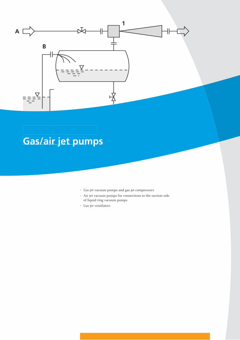
Grundlagen und Arbeitsblätter
• Gas jet vacuum pumps and gas jet compressors
• Air jet vacuum pumps for connections to the suction sideof liquid ring vacuum pumps
• Gas jet ventilators
Grundlagen und ArbeitsblätterGas/air jet pumps

aw 1
8
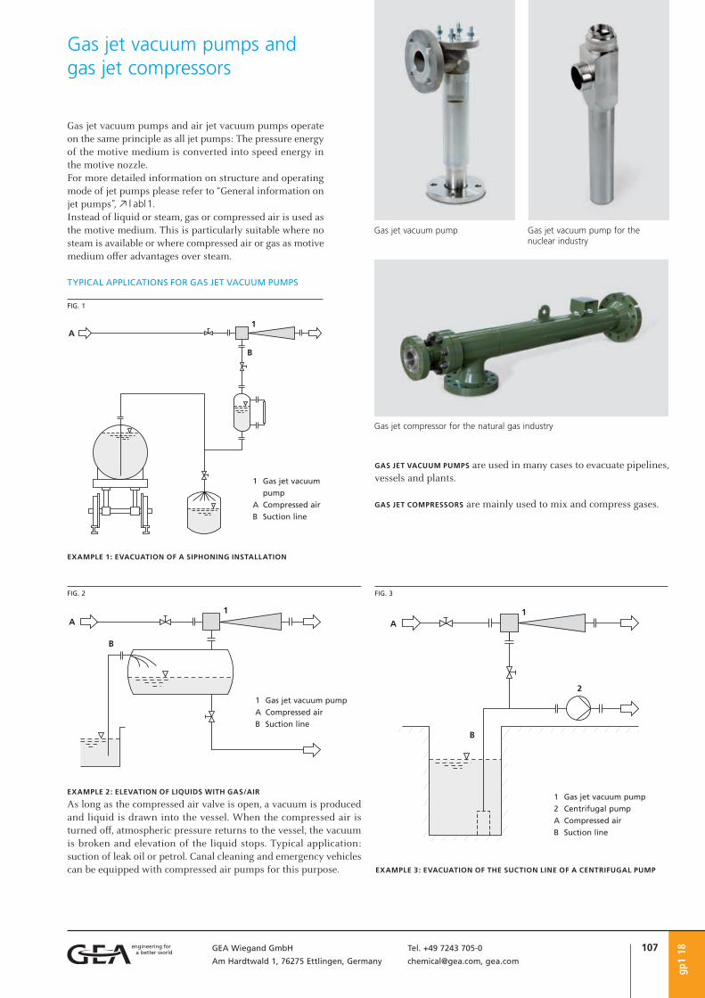
107GEA Wiegand GmbH Tel. +49 7243 705-0
Am Hardtwald 1, 76275 Ettlingen, Germany [email protected], gea.com
gp1
18
Gas jet vacuum pumps and gas jet compressors
EXAMPLE 2: ELEVATION OF LIQUIDS WITH GAS/AIR
As long as the compressed air valve is open, a vacuum is produced and liquid is drawn into the vessel. When the compressed air is turned off, atmospheric pressure returns to the vessel, the vacuum is broken and elevation of the liquid stops. Typical application: suction of leak oil or petrol. Canal cleaning and emergency vehicles can be equipped with compressed air pumps for this purpose.
TYPICAL APPLICATIONS FOR GAS JET VACUUM PUMPS
EXAMPLE 1: EVACUATION OF A SIPHONING INSTALLATION
FIG. 1
1 Gas jet vacuum
pump
A Compressed air
B Suction line
FIG. 2
1 Gas jet vacuum pump
A Compressed air
B Suction line
FIG. 3
1 Gas jet vacuum pump
2 Centrifugal pump
A Compressed air
B Suction line
EXAMPLE 3: EVACUATION OF THE SUCTION LINE OF A CENTRIFUGAL PUMP
GAS JET VACUUM PUMPS are used in many cases to evacuate pipelines, vessels and plants.
GAS JET COMPRESSORS are mainly used to mix and compress gases.
Gas jet vacuum pumps and air jet vacuum pumps operate on the same principle as all jet pumps: The pressure energy of the motive medium is converted into speed energy in the motive nozzle.For more detailed information on structure and operating mode of jet pumps please refer to “General information on jet pumps”, o | abl1.Instead of liquid or steam, gas or compressed air is used as the motive medium. This is particularly suitable where no steam is available or where compressed air or gas as motive medium offer advantages over steam.
Gas jet vacuum pump for the nuclear industry
Gas jet vacuum pump
Gas jet compressor for the natural gas industry
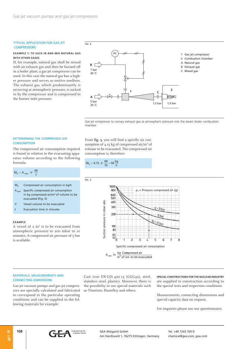
108 GEA Wiegand GmbH Tel. +49 7243 705-0
Am Hardtwald 1, 76275 Ettlingen, Germany [email protected], gea.com
Gas jet vacuum pumps and gas jet compressors
gp1
18
DETERMINING THE COMPRESSED AIR
CONSUMPTION
The compressed air consumption required is found in relation to the evacuating appa-ratus volume according to the following formula:
ØA Compressed air consumption in kg/h
A spec. Specific compressed air consumption
in kg compressed air/m³ of volume to be
evacuated (Fig. 5)
V Vessel volume to be evacuated
t Evacuation time in minutes
EXAMPLE
A vessel of 2 m³ is to be evacuated from atmospheric pressure to 200 mbar in 10 minutes. A compressed air pressure of 5 bar is available.
p1 = Pressure compressed air (g)
Suct
ion
pre
ssu
re i
n m
bar
ab
s.
Specific compressed air consumption
FIG. 5
FIG. 4
Gas jet compressor to convey exhaust gas at atmospheric pressure into the steam boiler combustion chamber
1 Gas jet compressor
2 Combustion chamber
A Natural gas
B Exhaust gas
C Mixed gas
TYPICAL APPLICATION FOR GAS JET
COMPRESSORS
EXAMPLE 1: TO SUCK IN AND MIX NATURAL GAS
WITH OTHER GASES
If, for example, natural gas shall be mixed with an exhaust gas and then be burned off in a boiler plant, a gas jet compressor can be used. In this case the natural gas has a high-er pressure and serves as motive medium. The exhaust gas, which predominantly is occurring at atmospheric pressure, is sucked in by the compressor and is compressed to the burner inlet pressure.
MATERIALS, MEASUREMENTS AND
CONNECTING DIMENSIONS
Gas jet vacuum pumps and gas jet compres-sors are specially calculated and fabricated to correspond to the particular operating conditions and can be supplied in the fol-lowing materials for example:
Cast iron EN-GJS-400-15 (GGG40), steel, stainless steel, plastics. Moreover, there is the possibility to use special materials such as Titanium, Hastelloy and others.
SPECIAL CONSTRUCTIONS FOR THE NUCLEAR INDUSTRY are supplied in construction according to the special tests and inspection conditions.
Measurements, connecting dimensions and special capacity data on request.
For inquiries please use our questionnaire.
From fig. 5, you will find a specific air con-sumption of 4.15 kg of compressed air/m³ of volume to be evacuated. The compressed air consumption is, therefore:

109GEA Wiegand GmbH Tel. +49 7243 705-0
Am Hardtwald 1, 76275 Ettlingen, Germany [email protected], gea.com
lvp1
18
Air jet vacuum pumps for connections to the suction side of liquid ring vacuum pumps
APPLICATIONS
• When no steam is available as motivemedium for a steam jet vacuum pumprequired to produce a vacuum of 40 to5 mbar.
• When a liquid ring pump is available witha suction capacity sufficient to handle themotive air of the air jet pump and whena suction pressure below 40 mbar is to beproduced.
• When a vacuum of 40 to 5 mbar is to beproduced and simple installation with lowcapital cost is important.
• When only a small suction capacity ata suction pressure of 40 to 50 mbar isrequired and cooling water at low tem-perature is available, because under thesecircumstances, the power consumption ofthe liquid ring vacuum pump is relativelylow.
Whenever it is a question of low energy con-sumption, it is better to connect a steam jet pump with condenser to the suction side of the liquid ring vacuum pump, whereby the motive medium (steam) of the jet pump is condensed and does not load the liquid ring vacuum pump as is the case with an air jet pump.
Air jet vacuum pumps use atmospheric air as motive medium. Backed by a liquid ring vacuum pump which produces an interme-diate vacuum of 50 to 100 mbar, the air jet vacuum pump can reach a suction pressure of 5 mbar, depending on design and operat-ing conditions.
FIG. 1
1 Air jet vacuum pump
2 Liquid ring vacuum pump
A Atmospheric air as motive medium
B Suction medium
C Atmosphere
p0 Suction pressure
p Discharge pressure of the air jet vacuum pump =
Suction pressure of the liquid ring vacuum pump
Method of operation of an air jet vacuum pump for connection to the suction side of a liquid ring vacuum pump
MATERIALS, CONSTRUCTION AND CONNECTING DIMENSIONS
Air jet vacuum pumps are specially calculated and fabricated to correspond to the particular operating conditions and can be supplied in the following materials: Cast iron EN-GJS-400-15 (GGG40), steel, stainless steel, plastics, porcelain. Further, special materials of construction are possible, such as Titanium, Hastelloy etc.
Dimensions, connecting dimensions and special capacity data on request.
For inquiries please use our questionnaire.
Air jet vacuum pump in stainless steel

110 GEA Wiegand GmbH Tel. +49 7243 705-0
Am Hardtwald 1, 76275 Ettlingen, Germany [email protected], gea.com
09
Questionnairefor gas jet vacuum pumps and gas jet compressors, gp1 air jet vacuum pumps , lvp1 gas jet ventilators, gv1
Company . . . . . . . . . . . . . . . . . . . . . . . . . . . . .
attn. . . . . . . . . . . . . . . . . . . . . . . . . . . . . . . . .
Street/P.O. Box . . . . . . . . . . . . . . . . . . . . . . . . .
ZIP code/City . . . . . . . . . . . . . . . . . . . . . . . . . .
Country . . . . . . . . . . . . . . . . . . . . . . . . . . . . . .
YOUR ADDRESS Telephone . . . . . . . . . . . . . . . . . . . . . .
Telefax . . . . . . . . . . . . . . . . . . . . . . . . .
E-mail . . . . . . . . . . . . . . . . . . . . . . . . .
Motive medium . . . . . . . . . . . . . . . . . .
Motive pressure . . . . . . . . . . . . . . . . . . bar abs.
Temperature . . . . . . . . . . . . . . . . . . . . . °C
1. MOTIVE SIDE Molecular weight . . . . . . . . . . . . . . . . . kg/kmol
Specific heat capacity . . . . . . . . . . . . . . kJ/kg K
Suction medium . . . . . . . . . . . . . . . . . .
Suction flow . . . . . . . . . . . . . . . . . . . . . kg/h
Suction pressure . . . . . . . . . . . . . . . . . . bar abs.
2. SUCTION SIDE Temperature . . . . . . . . . . . . . . . . . . . . . °C
Molecular weight . . . . . . . . . . . . . . . . . kg/kmol
Specific heat capacity . . . . . . . . . . . . . . kJ/kg K
Required discharge pressure . . . . . . . . . . bar abs.3. OUTLET Mixed flow . . . . . . . . . . . . . . . . . . . . . . kg/h
Additional details, if required, are to be stated separately.
Your inquiry no. . . . . . . . . . . . . . . . . . .
Offer submitted until . . . . . . . . . . . . . .
Requested date of delivery . . . . . . . . . . .
MATERIAL OF CONSTRUCTION . . . . . . . . . . . . . . . . . . . . . . . . . . . . . . . . . . . . . . . . . . . . . . . . .
CONNECTIONS:
Flanges
Thread
Others
4. FURTHER DATA
DESIGN CODE (if required):
AD-2000
ASME
Others
APPLICATION:
. . . . . . . . . . . . . . . . . . . . . . . . . . . . . .
. . . . . . . . . . . . . . . . . . . . . . . . . . . . . .
. . . . . . . . . . . . . . . . . . . . . . . . . . . . . .
DESIGN:
Temperature . . . . . . . . . . . . . . . . . . . . . °C Pressure . . . . . . . . . . . . . . . . . . . . . . . . bar g
FURTHER NOTES: . . . . . . . . . . . . . . . . . . . . . . . . . . . . . . . . . . . . . . . . . . . . . . . . . . . . . . . . . . .
. . . . . . . . . . . . . . . . . . . . . . . . . . . . . . . . . . . . . . . . . . . . . . . . . . . . . . . . . . . . . . . . . . . . . . .
. . . . . . . . . . . . . . . . . . . . . . . . . . . . . . . . . . . . . . . . . . . . . . . . . . . . . . . . . . . . . . . . . . . . . . .
FLANGES ACCORDING TO:
EN1092-1
ASME lbs
Others
Link to fillable PDF

111GEA Wiegand GmbH Tel. +49 7243 705-0
Am Hardtwald 1, 76275 Ettlingen, Germany [email protected], gea.com
gv1
18
APPLICATIONS
Gas jet ventilators convey air, gases and vapors against pressure diff erences up to approximately 500 mbar.Gas jet ventilators are used:• to draw off stale air, ill-smelling gases and
vapors from working and storage areas• to ventilate tanks, e.g. on ships• as forced blast blowers or stack ventilators
for boiler burners• for the circulation of air, in particular in
the textile, leather and tobacco industries• to deaerate reaction vessels, agitator
vessels and other items of equipment inchemical factories
The achievable pressure diff erence between the suction and discharge pressure is the compression of a gas jet ventilator.
ADVANTAGES
• no moving parts• maintenance free• installed in virtually all situations• immediately ready for operation• almost unlimited life, when a suitable
material of construction is chosen• manufactured from various materials of
construction• low acquisition costs
Steam or liquid may be used, instead of com-pressed air or gas, as the motive medium for jet ventilators; in this case, one would speak of steam jet ventilators (o | dv1) or liquid jetventilators (o | fv1).As opposed to liquid jet ventilators, gas or steam jet ventilators have the advantage that they can be installed in any installation
Gas jet ventilators
position and that larger pressure diff eren-tials can be obtained.
The characteristic lines apply to air as motive medium.In case the motive medium used is a gas other than air, the corresponding correction factors have to be considered.Gas jet ventilators operate in a range between Δp = 0 to 500 mbar. Above 500 mbar, gas jet compressors are used, o | gp1.
The motive medium consumption is calcu-lated as follows:
Ø0 Suction flow in kg/h
Ø1 Motive steam consumption in kg/h
(compressed air)
m Suction ratio in kg suction medium/
kg motive medium
EXAMPLES
Suction fl ow: 1500 kg/h air ¥ 1250 m³/h
Compressed air pressure: 2 bar (g)
1. Required compression Δp = 10 mbar
According to fi g. 1, with compressed air at2 bar, there is a suction ratiom = approx. 12.7 kg/kg.
2. Required compression Δp ~ 0 mbar According to fi g. 1, with compressed air at 2 bar, there is a suction ratio m = approx. 120 kg/kg.
Co
mp
ress
ion
Δp
in
mb
ar
p1 = Motive air pressure gauge
FIG. 1
DETERMINING THE MOTIVE MEDIUM
CONSUMPTION
Diagram fi g. 1 serves to roughly estimate the motive medium consumption. It shows the
suction ratio m in kg of suction medium per kg of motive medium in relation to the com-pression Δp in mbar, at various motive pres-sures in bar gauge.
Gas jet ventilator in stainless steel

112 GEA Wiegand GmbH Tel. +49 7243 705-0
Am Hardtwald 1, 76275 Ettlingen, Germany [email protected], gea.com
gv1
18
Gas jet ventilators
CONSTRUCTIONS OF GAS JET VENTILATORS
FIG. 3
Design with axial suction connection
FIG. 4
Design with lateral suction connection
APPLICATION SUCTION PLANT
An example for the deaeration of reaction vessels with a low-pressure gas jet ventilator.Here, air is fed into the gas jet ventilator as motive medium by a blower with low com-pression.As the blower is only in contact with atmos-pheric air, a standard design without special corrosion proofing is sufficient.The drawn off exhaust gases are heavily rar-efied by the motive air.For reasons of air pollution control the exhaust gas air mixture is usually supplied to an exhaust gas cleaning plant.
FIG. 2
Suction plant with a low-pressure gas jet
ventilator
1 Gas jet ventilator
2 Compressor
A Air
B Exhaust gas
C To exhaust gas
cleaning plant
MATERIALS, MEASUREMENTS AND CONNECTING DIMENSIONS
Gas jet ventilators are specially calculated and fabricated to correspond to the particular operating conditions and can be supplied in the following materials of construction:Cast iron EN-GJS-400-15 (GGG40), steel, stainless steel, plastics. Further, special materials of construction are possible, such as Titanium, Hastelloy etc.
Measurements, connecting dimensions and special capacity data on request.
For inquiries please use our questionnaire.

Grundlagen und Arbeitsblätter
• Vacuum systems
• Multi-stage steam jet vacuum pumps
• Multi-stage steam jet vacuum pumps in metal construction with mixing condensers
• Multi-stage steam jet vacuum pumps in metal construction with surface condensers
• Multi-stage steam jet vacuum pumps in metal construction with liquid ring vacuum pumps(hybrid system)
• Multi-stage steam jet vacuum pumps in graphite
• Arrangements of steam jet vacuum pumps
• Laboratory steam jet vacuum pumps
• Planning a steam jet vacuum pump
Grundlagen und ArbeitsblätterVacuum systems

gv1
18

115GEA Wiegand GmbH Tel. +49 7243 705-0
Am Hardtwald 1, 76275 Ettlingen, Germany [email protected], gea.com
ADVANTAGES AND OPERATION OF A STEAM
JET VACUUM PUMP
Steam jet vacuum pumps are pumps with-out moving parts. They consist of the main components head, motive nozzle and diffus-er which again consists of the inlet cone, the mixing nozzle and the discharge cone. Struc-ture and mode of operation can be divided into three main processes:• flashing the motive steam in the motive
nozzle and formation of a directed steamjet
• mixing of the steam jet with the mediumto be sucked in (air, gases and steam)
• conversion of the velocity of the mixtureinto pressure in the mixing nozzle anddischarge cone
ADVANTAGES:
• no moving parts• almost any vacuum duty can be accom-
modated including large suction flows• low maintenance costs• long equipment life• reliable operation • low operating costs if operated correctly• manufacture possible in different
materials
For further details on the mode of operation of jet pumps please refer to section “General information on jet pumps”, o | abl1.Steam jet pumps are particularly suited as vacuum pumps as the large volumes can be easily handled in the vacuum due to the very high gas velocities.
When selecting steam jet vacuum pumps, their special performance characteristics must be taken into account to ensure proper and most effective operation. This document is designed to provide general information regarding the operation of steam jet vacu-um pumps. It is not intended as a substitute for the assistance of our experienced engi-neers who are at your disposal to ensure the best equipment selection for meeting your requirements.
gdp1
18
Vacuum systems
1 Head
2 Motive nozzle
3 Inlet cone
4 Mixing nozzle
5 Discharge cone
p0 Suction pressure
p1 Motive steam
pressure
p Discharge pressure
BILD 1
Cross section of a steam jet vacuum pump

116 GEA Wiegand GmbH Tel. +49 7243 705-0
Am Hardtwald 1, 76275 Ettlingen, Germany [email protected], gea.com
Multi-stage steam jet vacuum pumps are used to produce vacuum in evaporators, driers, distillation plants, rectifying, freeze drying, poly-condensation, degassing, deo-dorizing plants etc. The compression ratio of a single stage steam jet vacuum pump is limited (1:10, max. 1:20). Therefore, for low suction pressures, several jet vacuum pumps are arranged in series. A condenser is arranged between two jet pumps in order to condense the motive steam as far as possible. In this way, the volume of the complete gas mixture and thus the energy requirement of the next stage is reduced. Such multi-stage steam jet vacuum pumps are constructed for suction pressures up to approx. 0.01 mbar.To compress process gases from a pres-sure of 0.3 mbar to a condenser pressure of 56 mbar (i.e. a compression ratio of 56 : 0.3 ≅ 187), two jet stages are just suffi-cient, each handling a compression ratio of approx. 14. For a suction pressure of 0.1 mbar, the pressure gradient is 56 : 0.1 ≅ 560, and therefore, 3 jet pumps must be arranged in series, each handling a compression ratio of 8.25 per stage. The maximum compres-sion ratio for a steam jet vacuum pump depends on the suction pressure and the pressure of the available motive steam.
The condensers used are water-cooled mix-ing condensers or surface condensers, in some individual cases, even air-cooled con-densers are used.
Steam jet vacuum pumps with mixing con-densers are used where the extracted medium is allowed to get in contact with the cooling water and where the recovery of condensate is not required.If, however, the contact with cooling water is not allowed, such as for example, if there is ammonia and chalky water, or if condensed product or motive steam condensate has to be recovered, surface condensers have to be used instead of mixing condensers.
For steam jet pumps for suction pressure of less than 6 mbar the head and the mixing nozzle are heated, depending on the instal-lation position. In this way, the formation of ice inside the pump is avoided which other-wise could lead to trouble.If steam jet vacuum pumps are required for the extraction of steams which contain any constituents with a high melting point (e.g. caprolactam, oligomers, low polymers in poly-condensation plants, etc.), heat jacketing is recommended even for higher suction pressure levels. For processes involv-ing fluids with very high melting points, the ejectors are heated by means of vaporous or liquid diphyl, high temperature resistant oils or any other heat carrier fluid.
Steam jet vacuum pumps are mainly oper-ated with water steam. Water steam is easily available in industry and proved well as motive fluid for jet pumps. In special cases in which the product condensate must not be diluted by or mixed with water steam condensate, steam jet pumps are operated on product steam.
Steam jet vacuum pumps can be manufac-tured of different materials, mainly:• for jet pumps: cast iron, steel, stainless
steel• for condensers: steel, rubberized or
enamelled steel, stainless steel, bronze orother special alloys
For applications in which metallic materials are not resistant, steam jet vacuum pumps in graphite are used.
For more detailed information on the dis-cussed topics please refer to section “Plan-ning a steam jet vacuum pump”, o | gdp3.
Multi-stage steam jet vacuum pumpsgd
p1 1
8

117GEA Wiegand GmbH Tel. +49 7243 705-0
Am Hardtwald 1, 76275 Ettlingen, Germany [email protected], gea.com
DESIGN AND MODE OF OPERATION
FIVE-STAGE STEAM JET VACUUM PUMP WITH
MIXING CONDENSERS FOR 1 mbar (FIG. 1)
STAGE 1: extracts the vapors and gases from the process to be kept under vacuum; final vacuum e.g. 2 mbarSTAGE 2: compresses both the motive steam and the extracted vapors and gases of the 1st stage to a pressure of approx. 55 mbarMIXING CONDENSER I : is designed for a con-densation pressure level which is as low as possible to keep the steam consumption as low as possible. The suction flow load of the downstream-arranged stages and their steam requirements are thereby reduced.STAGE 3: extracts all gases and vapors which were not condensed in the upstream mixing condenser I for compression to a pressure of 160 mbarMIXING CONDENSER II : reduces the suction flow in order to relieve the downstream arranged stagesSTAGE 4: compresses to a pressure of 400 mbarMIXING CONDENSER III : condenses the remain-ing suction flow and the motive steam of the upstream arranged stageSTAGE 5: compresses to atmospheric pressure for discharge to the ambient air via a scrub-ber or a mixing condenser
Mixing condensers are internally fitted with baffles or nozzles to enhance water distri-bution. They are shaped such that fouling problems are minimized. The cooling water is best drained off through barometric legs.
See also “Planning a steam jet vacuum pump”, o | gdp3.
Multi-stage steam jet vacuum pumps in metal construction with mixing condensers
dpm
1 18
A Motive steam
B Suction connection
C Cooling water
1 – 5 Steam jet vacuum pumps, stages 1 to 5
I – III Mixing condensers
5-stage steam jet vacuum pump with mixing condenser
FIG. 1
Suction capacity: 17 kg/h from 1 mbar, corresponding to 7230 m³/h and 3.6 kg/h from 2 mbar, corresponding to 1500 m³/h

118 GEA Wiegand GmbH Tel. +49 7243 705-0
Am Hardtwald 1, 76275 Ettlingen, Germany [email protected], gea.com
Fig. 2
3-stage steam jet vacuum pump with mixingcondensers
Suction capacity: 3380 kg/h steam and 225 kg/h of inert gas from 60 mbar
Fig. 3
3-stage steam jet vacuum pump with mixingcondenser and liquid jet vacuum pump in apolyester production plant
dpm
1 18
Multi-stage steam jet vacuum pumps in metal construction with mixing condensers
Fig. 4
Vacuum unit for a MED plant for sea water desalination with a capacity of 800 t/h of destillate

119GEA Wiegand GmbH Tel. +49 7243 705-0
Am Hardtwald 1, 76275 Ettlingen, Germany [email protected], gea.com
DESIGN AND MODE OF OPERATION
FOUR-STAGE STEAM JET VACUUM PUMP WITH
SURFACE CONDENSER FOR 1 mbar (FIG. 1)
STAGE 1: extracts the vapors and gases from the process to be kept under vacuum; final vacuum e.g. 2 mbarSTAGE 2: compresses both the motive steam and the extracted vapors and gases dis-charged by the 1st pump stage to a pressure of 80 mbarSURFACE CONDENSER I : is designed for a con-densation pressure level which is as low as possible to keep the steam consumption as low as possible. The suction flow load of the downstream-arranged stages and their steam requirements are thereby reduced.STAGE 3: stage extracts all gases and vapors which were not condensed in the surface condenser I for compression to a pressure of 320 mbarSURFACE CONDENSER II : reduces the suction flow in order to relieve the downstream arranged stagesSTAGE 4: compresses to atmospheric pressure for discharge to the ambient air via a scrub-ber or a surface condenserSURFACE CONDENSER III : condenses the remain-ing suction flow and the motive steam of the upstream arranged stage
See also “Planning a steam jet vacuum pump”, o | gdp3.
3-stage steam jet vacuum pump downstream of the 1st stage (pre-stage, heated), suction capacity: 3462 kg/h from 26.7 mbar abs.
dpo1
18
Multi-stage steam jet vacuum pumps in metal construction with surface condensers
IIIIII
ABCDE123451I
A Motive steam
B Suction connection
C Cooling water
1 – 4 Steam jet vacuum pumps, stages 1 to 4
I – III Surface condenser
4-stage steam jet vacuum pump with surface condensers
FIG. 1

120 GEA Wiegand GmbH Tel. +49 7243 705-0
Am Hardtwald 1, 76275 Ettlingen, Germany [email protected], gea.com
dpo1
18
Multi-stage steam jet vacuum pumps In metal construction with surface condensers
Fig. 2
3-stage steam jet vacuum pump with several lateralflows (10 jet pumps in total) for the production ofmono-ethylene glycole (plastics industries)
Total suction flow: approx. 1 050 kg from different pressure levels
Fig. 3
2-stage steam jet vacuum pump with surfacecondenser, completely in Hastelloy
Suction capacity: 110 kg/h from 35 mbar
Fig. 4
3-stage steam jet vacuum pump with surfacecondenser for the vacuum column of a refinery
Suction flow: 13 180 kg/h (436 000 m³/h)Suction pressure abs.: 4.5 kPa abs.Discharge pressure abs.: 110 kPa abs.

121GEA Wiegand GmbH Tel. +49 7243 705-0
Am Hardtwald 1, 76275 Ettlingen, Germany [email protected], gea.com
DESIGN AND MODE OF OPERATION
Steam jet liquid ring vacuum pumps are especially suited if the permissible height of the installation is limited, i.e. if a baromet-ric installation is not possible. Thanks to the combination of steam jet pumps and a liquid ring vacuum pump the steam and water consumption values are low. Compared to a steam jet vacuum pump only, the operating costs are lower.The hybrid system is delivered as compact unit in a steel frame.
TWO-STAGE PUMP FOR A NOMINAL SUCTION
PRESSURE OF 1 mbar (FIG. 1)
The 2nd stage is connected to the vacuum plant and extracts the vapors and gases or air and compresses it to approx. 13 mbar. The 2nd stage conveys it and compresses to approx. 90 mbar. The motive steam con-denses in the surface condenser. The liquid ring vacuum pump extracts all non-condens-ables and the occurring condensate from the surface condenser and conveys it to atmo-spheric pressure.
See also “Planning a steam jet vacuum pump”, o | gdp3.
dwp1
18
Multi-stage steam jet vacuum pumps in metal construction with liquid ring vacuum pumps (hybrid system)
Suction capacity: 4.5 kg/h of air/benzyl alcohol from 2 mbar
A Motive steam
B Suction connection
C Cooling water
1 – 2 Steam jet pumps,
stages 1 and 2
I Surface condenser
2-stage steam jet liquid ring vacuum pump
FIG. 1
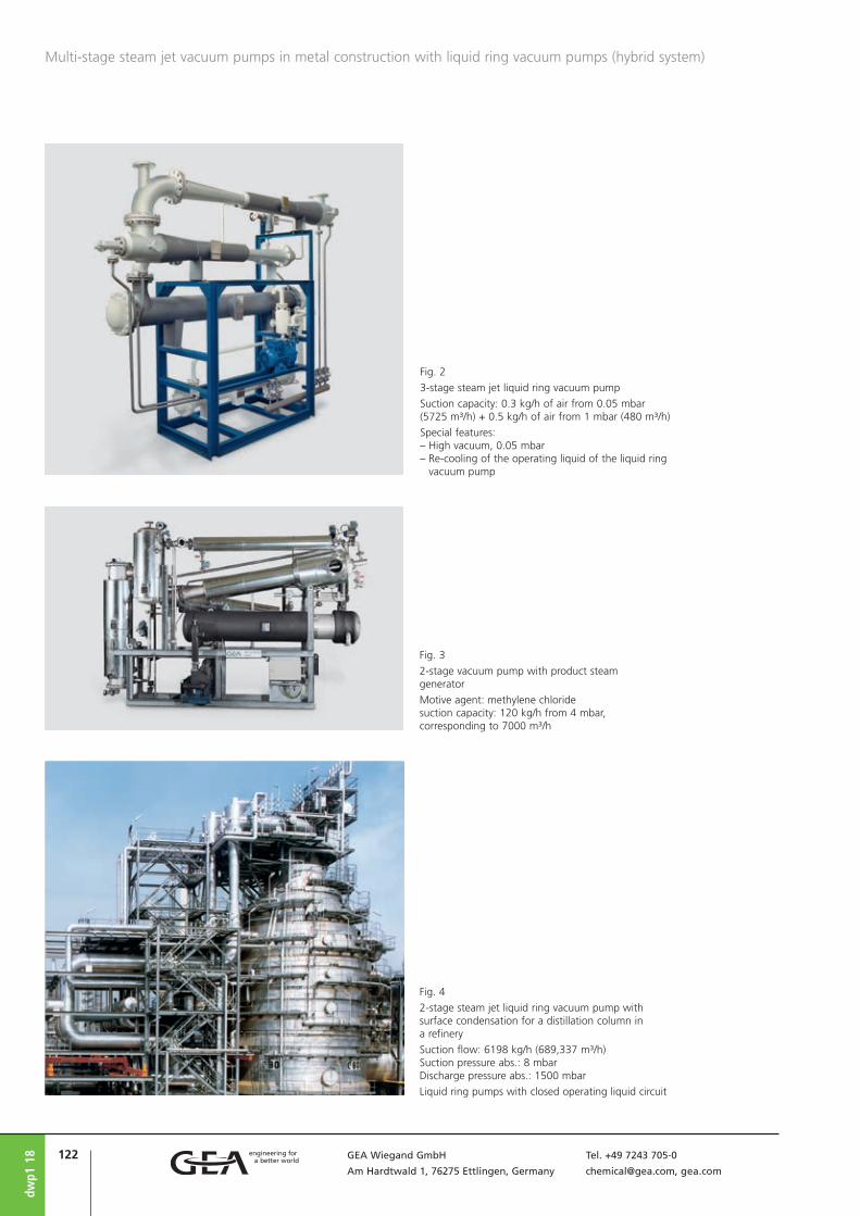
122 GEA Wiegand GmbH Tel. +49 7243 705-0
Am Hardtwald 1, 76275 Ettlingen, Germany [email protected], gea.com
dwp1
18
Multi-stage steam jet vacuum pumps in metal construction with liquid ring vacuum pumps (hybrid system)
Fig. 2
3-stage steam jet liquid ring vacuum pump
Suction capacity: 0.3 kg/h of air from 0.05 mbar (5725 m³/h) + 0.5 kg/h of air from 1 mbar (480 m³/h)
Special features: – High vacuum, 0.05 mbar – Re-cooling of the operating liquid of the liquid ring
vacuum pump
Fig. 3
2-stage vacuum pump with product steam generator
Motive agent: methylene chloridesuction capacity: 120 kg/h from 4 mbar, corresponding to 7000 m³/h
Fig. 4
2-stage steam jet liquid ring vacuum pump with surface condensation for a distillation column in a refinery
Suction flow: 6198 kg/h (689,337 m³/h)Suction pressure abs.: 8 mbarDischarge pressure abs.: 1500 mbar
Liquid ring pumps with closed operating liquid circuit

123GEA Wiegand GmbH Tel. +49 7243 705-0
Am Hardtwald 1, 76275 Ettlingen, Germany [email protected], gea.com
DESIGN AND MODE OF OPERATION
Multi-stage steam jet vacuum pumps in graphite are used to extract corrosive gases and vapors, particularly where halogen com-pounds are present, if stainless steels are not sufficiently resistant.
FOUR-STAGE STEAM JET VACUUM PUMP FOR 2 mbar,
(FIG. 1)
STAGE 1: extracts the vapors and gases from the process to be kept under vacuum; final vacuum e.g. 2 mbarSTAGE 2: compresses the motive steam and the extracted vapor and gases of stage 1 to 75 mbarSURFACE CONDENSER CHAMBER I : is designed for a condensation pressure level which is as low as possible to keep the steam consump-tion as low as possible. The suction flow load of the downstream-arranged stages and their steam requirements are thereby reduced.STAGE 3: extracts all gases and vapors which were not condensed in the upstream con-denser chamber I for compression to a pres-sure of approx. 320 mbarSURFACE CONDENSER CHAMBER II : reduces the suction flow in order to relieve the down-stream arranged stagesSTAGE 4: extracts all non-condensable gases and vapor from condenser chamber II and compresses them to atmospheric pressure.SURFACE CONDENSER CHAMBER III : will only be required if the exhaust gases are not allowed to reach the open air. The inert gases are dis-charged silently and without steam trailing.
The condensate lines can be made in plastic or graphite tubes.In the here described steam jet vacuum pump the extracted medium does not come into contact with the cooling water.If the extracted medium is allowed to get into contact with the cooling water, we recommend the use of our multi-stage steam jet vacuum pumps made of graphite, where mixing condensers of temperature-change resistant enamelled steel are used for inter-condensation (Fig. 2).
Steam jet vacuum pump with jet pumps and block condenser made of graphite
pgv1
18
Multi-stage steam jet vacuum pumps in graphite
A Motive steam
B Suction connection
C Cooling water
4-stage steam jet vacuum pump with compact block condenser
FIG. 1
1 – 4 Jet pumps, stages 1 to 4
I – II Intermediate condenser chambers
III After-condenser chamber

124 GEA Wiegand GmbH Tel. +49 7243 705-0
Am Hardtwald 1, 76275 Ettlingen, Germany [email protected], gea.com
constructed as modular units from standard elements.
SPECIAL CONSTRUCTIONS can easily be built as modular units from standard parts. By using different combinations of standard parts, most intermediate duties are attainable.
SPARE PARTS for graphite jet pumps are manu - factured on demand at short notice thanks to high standardization.
REVAMPING OF EXISTING PLANTS
Graphite jet pumps replace existing porce-lain jet pumps without any on-site modifi-cations. The installation dimensions remain unchanged.By means of graphite jet pumps, existing steam jet vacuum plants can be optimized in terms of energy consumption and perfor-mance.
MATERIALS AND CONSTRUCTION
GRAPHITE is used for the construction of sur-face condensers and jet pumps in all cases where the usual corrosion and acid proof materials are not resistant enough. On account of its excellent thermal conductiv-ity and its high resistance to temperature change, graphite is ideal for heat exchang-ers and jet pumps. Gas-tightness is achieved by means of impregnation. Jet pumps made of graphite and operated in vacuum below 3 mbar can be heated to eliminate ice formation. As surface condensers, block heat exchang-ers, shell-and-tube heat exchangers or also plate heat exchangers from graphite of all commercial makes are used which are suit-able to condense vapors under vacuum.
STANDARD CONSTRUCTIONS are supplied for suction capacities of 1 kg/h to 10 kg/h at suction pressures from 1 to 10 mbar; there-by meeting most requirements. Pumps are
pgv1
18
Multi-stage steam jet vacuum pumps in graphite
Fig. 2
5-stage steam jet vacuum pump in corrosion-resistant design
Materials: jet pumps in graphite, mixing condensers in C-steel, enamelled Suction capacity: 5 kg/h of air from 2.5 mbar abs.

125GEA Wiegand GmbH Tel. +49 7243 705-0
Am Hardtwald 1, 76275 Ettlingen, Germany [email protected], gea.com
gdp2
18
Arrangements of steam jet vacuum pumps
Single-stage steam jet vacuum pump for suction pressures down to 100 mbar at atmospheric discharge pressure. The compression ratio p/p0 is generally limited to p/p0 ≤ 10.Typical application: pre-evacuator
Two-stage steam jet vacuum pump without inter-stage condenser, for suction pressures down to approx. 40 mbar, at atmospheric discharge pressure.Typical applications: two-stage pre-evacuator or for small suction flow
FIGURES 1-2 FIGURES 3-4
FIG. 1 FIG. 3
FIG. 4
FIG. 2
A Motive steam
B Suction connection
C Cooling water
A Motive steam
B Suction connection
C Cooling water
A Motive steam
B Suction connection
C Cooling water
Three-stage steam jet vacuum pump with 2 inter-stage condensers (I, II), for suction pressures down to approx. 10 mbar.These pumps consume less steam and water than two-stage pumps with inter-stage condensers (fig. 3) sized for the same duty.
3-stage steam jet vacuum pump
Single-stage steam jet vacuum pump
2-stage steam jetvacuum pump
2-stage steam jet vacuum pump
Two-stage steam jet vacuum pump with inter-stage condenser I (mixing con-densation), for suction pressures down to approx. 40 mbar. Mainly used for the evacuation of condensers imposing low air loads.

126 GEA Wiegand GmbH Tel. +49 7243 705-0
Am Hardtwald 1, 76275 Ettlingen, Germany [email protected], gea.com
Arrangements of steam jet vacuum pumps
gdp2
18
Five-stage steam jet vacuum pump utilizes 3 pre-stages upstream of the 1st condenser and 2 inter-stage con-densers, for suction pressure up to approx. 0.01 mbar.Typical applications: The same as fig. 6. • Depending on the suction capacity and on the water
temperature, liquid ring vacuum pumps can be used in the range of 60 up to approximately 200 mbar for the air extraction and pre-evacuation of the 1st or 2nd inter-stage condenser (fig. 3 to 7). This kind of com-bination is based on the fact that it offers the opera-tional advantages over a normal steam jet pump and that there are no objections with regard to the mate-rials. See also “Planning a steam jet vacuum pump”, o | gdp3.
• Surface condensers can also be used in place of mix-ing condensers (see fig. 10) when contact between extracted process fluid and cooling water is not accept-able, or in case the condensate is to be recovered.
FIGURE 7
FIG. 7
FIGURES 5-6
FIG. 5
FIG. 6
Four-stage steam jet vacuum pump with 3 mixing condensers (I, II, III), for suction pressures ranging from 2 to 10 mbar, used to extract air, gases, and vapors from various types of vacuum plants
4-stage steam jet vacuum pump
4-stage steam jet vacuum pump
Four-stage steam jet vacuum pump utilizes 2 stages upstream of the 1st of the 3 inter-stage condensers (I, II, III), for suction pressures ranging from 0.5 to 2 mbar and suction flows of approx. 0.5 kg/h to several 1000 kg/h. A two-stage steam jet vacuum pump according to fig. 3 to de-aerate the first condenser will be sufficient if the inert gas load is low in the suction flow is low and the motive steam pressure sufficiently high.Typical applications: generation of vacuum for synthetic fibre production plants – especially polyester condensation, further, distillation, steel degassing, deodorizing, vacuum drying etc.
A Motive steam
B Suction connection
C Cooling water
A Motive steam
B Suction connection
C Cooling water
A Motive steam
B Suction connection
C Cooling water
5-stage steam jet vacuum pump
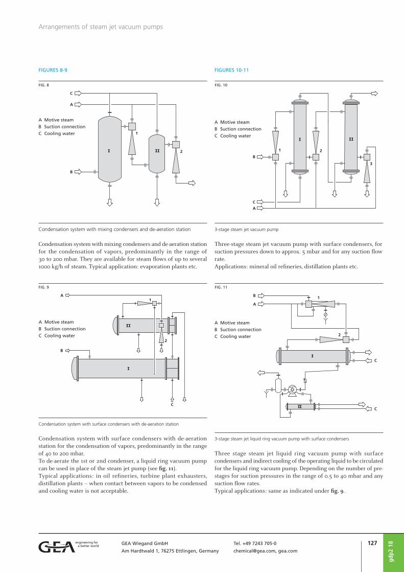
127GEA Wiegand GmbH Tel. +49 7243 705-0
Am Hardtwald 1, 76275 Ettlingen, Germany [email protected], gea.com
gdp2
18
Arrangements of steam jet vacuum pumps
Condensation system with mixing condensers and de-aeration station
Condensation system with mixing condensers and de-aeration station for the condensation of vapors, predominantly in the range of 30 to 200 mbar. They are available for steam flows of up to several 1000 kg/h of steam. Typical application: evaporation plants etc.
FIGURES 8-9
FIG. 8
A Motive steam
B Suction connection
C Cooling water
FIG. 9
Condensation system with surface condensers with de-aeration station for the condensation of vapors, predominantly in the range of 40 to 200 mbar.To de-aerate the 1st or 2nd condenser, a liquid ring vacuum pump can be used in place of the steam jet pump (see fig. 11). Typical applications: in oil refineries, turbine plant exhausters, distillation plants – when contact between vapors to be condensed and cooling water is not acceptable.
A Motive steam
B Suction connection
C Cooling water
Condensation system with surface condensers with de-aeration station
FIG. 11
Three stage steam jet liquid ring vacuum pump with surface condensers and indirect cooling of the operating liquid to be circulated for the liquid ring vacuum pump. Depending on the number of pre-stages for suction pressures in the range of 0.5 to 40 mbar and any suction flow rates.Typical applications: same as indicated under fig. 9.
A Motive steam
B Suction connection
C Cooling water
3-stage steam jet liquid ring vacuum pump with surface condensers
Three-stage steam jet vacuum pump with surface condensers, for suction pressures down to approx. 5 mbar and for any suction flow rate.Applications: mineral oil refineries, distillation plants etc.
FIGURES 10-11
FIG. 10
A Motive steam
B Suction connection
C Cooling water
3-stage steam jet vacuum pump

128 GEA Wiegand GmbH Tel. +49 7243 705-0
Am Hardtwald 1, 76275 Ettlingen, Germany [email protected], gea.com
gdp2
18
Arrangements of steam jet vacuum pumps
Multi-stage steam jet vacuum pump with surface condenser and discontinuous condensate trap, via alternately working condensate feed tanks. Used for suction pressures ranging from 0.1 to 10 mbar.
Multi-stage laboratory steam jet vacuum pump with a liquid jet vacuum pump, for suction pressures ranging from 0.05 to 5 mbar and small suction flows. Available with and without cooling water re-circulation.A water jet pump (3) will be used for condensation.
One or multi-stage steam jet liquid ring vacuum pump with surface condenser, for suction pressures ranging from 0.5 to 30 mbar and small and medium suction flows (see also fig. 11).
One or multi-stage steam jet liquid ring vacuum pump
Multi-stage steam jet vacuum pump
FIGURE 12 FIGURES 13-14
FIG. 12 FIG. 13
A Motive steam
B Suction connection
C Cooling water
A Motive steam
B Suction connection
C Cooling water
Multi-stage laboratory steam jet vacuum pump
FIG. 14
A Motive steam
B Suction connection
C Cooling water

129GEA Wiegand GmbH Tel. +49 7243 705-0
Am Hardtwald 1, 76275 Ettlingen, Germany [email protected], gea.com
Laboratory steam jet vacuum pumps are used as vacuum producers in chemical labo-ratories, for pilot plants and in small produc-tion plants. Here, they are mostly required for processes operating discontinuously or needing vacuum for short operation periods.
Laboratory steam jet vacuum pumps consist of two steam jet stages connected in series and backed by a liquid jet vacuum pump. Unlike the multi-stage steam jet vacuum pumps they do not use any drain pumps or barometric legs. The specific steam and cooling water requirements are higher in comparison to multi-stage steam jet vacuum pumps which are designed to operate continuously for longer operation periods.
Laboratory steam jet vacuum pumps are portable. The larger packages are supplied with castors unless they are required for sta-tionary use. They can be quickly connected via short suction lines to any vacuum con-sumer. This is an important feature because branched suction lines incl. shut-off valves etc. are eliminated. The possibility of leak-age air entering and consequently, the pull-down time are reduced. This is of increased significance for higher operation vacuum levels.
The water consumption of the laboratory steam jet vacuum pumps is relatively high as the jet vacuum pump does not only serve to condense but also to compress the air and gases to atmospheric pressure. The fresh water requirement can be reduced by utiliz-ing water re-circulation.
When cooling water consumption is an important factor, the laboratory steam jet vacuum pumps are supplied with a complete water recirculation system. This consists of the following: water tank, pump incl. motor, water temperature controller, automatic cooling water supply valve, thermometer and interconnecting piping between pump and jet condenser. All re-circulation system parts are protected against corrosion.The automatic cooling water supply valve ensures that the water temperature is kept within permissible limits.
If required, laboratory steam jet vacuum pumps can even be delivered without water circulation system.
ldp1
18
Laboratory steam jet vacuum pumps
As a rough guide to the selection of a pump model, the following “rule of thumb” can be applied:The volume of the system to be evacuated expressed in m³ equals the required suction capacity in kg/h.For example for an apparatur with 0.5 m3 content = suction capacity of 0.5 kg/h.
CAPACITY AND CONSUMPTION DATA
Laboratory steam jet vacuum pumps are available in several sizes and materials as standardized units.The following table lists the available models. The model designations indicate the suction capacity and suction pressure, and whether they are designed for once through or re-circulated cooling water.Model number 01.1-K denominates a labora-tory steam jet vacuum pump with a suction capacity of 0.1 kg/h of air at a suction pres-sure of 1 mbar. K means “with cooling water re-circulation”.The table indicates the design capacity and the associated suction pressure of each pump model and the suction pressure achieved with the delivery flow = 0 (so-called ead end vacuum).
Each jet pump can be turned off individually. This permits stable operation even at high-er suction pressure ranges. Alternatively, the operating suction pressures can be elevated by admitting “ballast” steam to the pump inlet.
Designation Suction flowWater
consumption
Steam
consumption
Evacuation time
for a unit volume
kg/h air from mbar m³/h m³/h from m³ minutes
01.1
0.3
0.1
0.0
1.50
1.00
0.75
3.4 25 0.2 10
01.1-K
0.3
0.1
0.0
1.50
1.00
0.75
0.6-2.5 25 0.2 10
05.30.5
0.0
2.80
1.40 3.9 40 0.5 18
05.3-K0.5
0.0
2.80
1.40 1-2.5 40 0.5 18
1.21.0
0.0
2.00
1.00 5.5 75 1.0 15
1.2-K1.0
0.0
2.00
1.00 2-4 75 1.0 15

130 GEA Wiegand GmbH Tel. +49 7243 705-0
Am Hardtwald 1, 76275 Ettlingen, Germany [email protected], gea.com
ldp1
18

131GEA Wiegand GmbH Tel. +49 7243 705-0
Am Hardtwald 1, 76275 Ettlingen, Germany [email protected], gea.com
Most important points to be considered when designing steam jet vacuum pumps:
• suction flow
• suction pressure (vacuum)
• type of condensation
• type of installation
• motive steam properties – water steamor product steam?
• cooling water properties
• materials of construction
• evacuation time
• steam jet vacuum pump versus steam jetpump /liquid ring vacuum pump com-bination
1. SUCTION FLOW
The steam consumption of a steam jet vacu-um pump depends on whether the complete suction flow is to be conveyed or only a part of it. For this reason, the max. suction flow has to be determined as precisely as possible for the design of the pump. In most of the cases, steam jet vacuum pumps are designed for and operated under a determined suction pressure. Therefore, the mass flows and the molecular weights are decisive factors for the design of a jet pump. For mechanical pumps, however, the suction flow is frequently measured as volume flow in m³/h.
1.1 GASES AND VAPORS RELEASED BY THE PRODUCT
TO BE TREATED IN THE PLANT
Generally, the non-condensable and conden-sable constituents of the suction flow must be differentiated. See also “Vapors and gases in vacuum” and “Water vapor and air in vacuum”, o | abl7.To determine the condensability of the vapors involved, their vapor pressure curves and molecular weights of the substances in question (boiling point depends on the pressure) are required. Additionally, for discontinuous processes, it is important to know at which vacuum gases or vapors are released. If, for example, for a drying process a total of 200 kg of water steam has to be extracted and if already approx. 90 % have a pressure of 1000 and 50 mbar, the energy requirement is rather low.If, however, the 200 kg of steam have to be extracted only in the range between 10 and 1 mbar, the energy requirement is much higher. Even the temperature of the gases or vapors to be extracted is very important for the design of a steam jet vacuum pump.
1.2 AIR AND GASES RELEASED FROM THE COOLING
WATER
The cooling water normally contains dis-solved air and gases. These are released under vacuum. The quantities of air in solu-tion depend on the saturation. Fig 1 illus-trates the relationship. Attention should be paid to the possibility of air bubbles and CO2 being present in the cooling water. These are released under vac-uum and, hence, to be added to the steam jet vacuum pump suction flow requirement.
1.3 LOAD SPLITTING
When the actual leakage air flow cannot be accurately determined, excessive safety margins are often applied when theoreti-cally determining the suction flow for a vacuum pump.See also “Air leakage into vacuum vessels”, o | abl8.This entails increased motive steam con-sumption rates, even if later the air leak-age amount is not as high as assumed. The steam consumption depends on whether the complete suction flow is to be conveyed or only a part of it; it remains constant.One way to avoid this is by dividing the total duty into parallel streams and the use of parallel steam jet vacuum pumps, e. g. one pump for 1/3 and the second for 2/3 of the capacity. When the real requirement is known, after plant start-up, one or the other of the jet pumps can be turned off to save motive steam and cooling water.The additional investment is in a set of shut-off valves for each suction connection and motive steam supply line to the jet pumps.
gdp3
18
Planning a steam jet vacuum pump
Water temperature in ˚C
Dis
solv
ed a
ir i
n w
ater
g/m
3
Solubility of air in water at saturation
FIG. 1
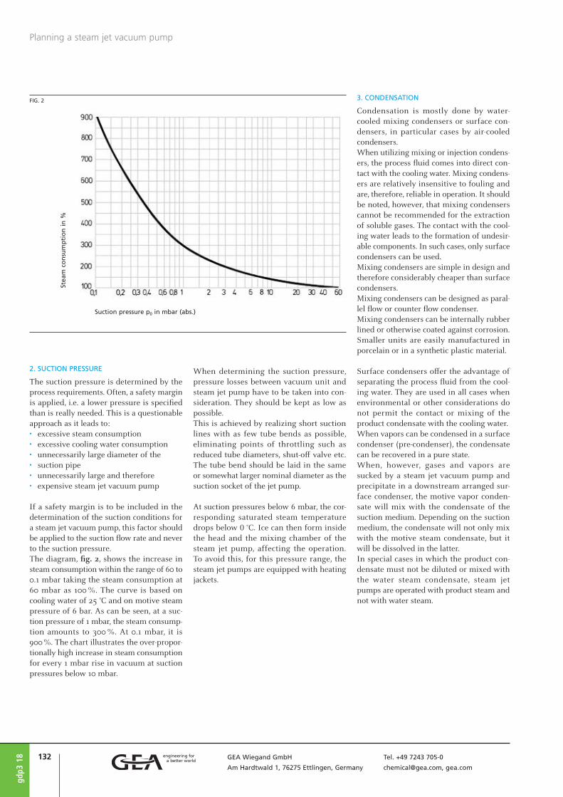
132 GEA Wiegand GmbH Tel. +49 7243 705-0
Am Hardtwald 1, 76275 Ettlingen, Germany [email protected], gea.com
gdp3
18
2. SUCTION PRESSURE
The suction pressure is determined by the process requirements. Often, a safety margin is applied, i.e. a lower pressure is specified than is really needed. This is a questionable approach as it leads to: • excessive steam consumption• excessive cooling water consumption• unnecessarily large diameter of the • suction pipe• unnecessarily large and therefore • expensive steam jet vacuum pump
If a safety margin is to be included in the determination of the suction conditions for a steam jet vacuum pump, this factor should be applied to the suction flow rate and never to the suction pressure.The diagram, fig. 2, shows the increase in steam consumption within the range of 60 to 0.1 mbar taking the steam consumption at 60 mbar as 100 %. The curve is based on cooling water of 25 °C and on motive steam pressure of 6 bar. As can be seen, at a suc-tion pressure of 1 mbar, the steam consump-tion amounts to 300 %. At 0.1 mbar, it is 900 %. The chart illustrates the over-propor-tionally high increase in steam consumption for every 1 mbar rise in vacuum at suction pressures below 10 mbar.
When determining the suction pressure, pressure losses between vacuum unit and steam jet pump have to be taken into con-sideration. They should be kept as low as possible.This is achieved by realizing short suction lines with as few tube bends as possible, eliminating points of throttling such as reduced tube diameters, shut-off valve etc. The tube bend should be laid in the same or somewhat larger nominal diameter as the suction socket of the jet pump.
At suction pressures below 6 mbar, the cor-responding saturated steam temperature drops below 0 °C. Ice can then form inside the head and the mixing chamber of the steam jet pump, affecting the operation. To avoid this, for this pressure range, the steam jet pumps are equipped with heating jackets.
3. CONDENSATION
Condensation is mostly done by water-cooled mixing condensers or surface con-densers, in particular cases by air-cooled condensers.When utilizing mixing or injection condens-ers, the process fluid comes into direct con-tact with the cooling water. Mixing condens-ers are relatively insensitive to fouling and are, therefore, reliable in operation. It should be noted, however, that mixing condensers cannot be recommended for the extraction of soluble gases. The contact with the cool-ing water leads to the formation of undesir-able components. In such cases, only surface condensers can be used.Mixing condensers are simple in design and therefore considerably cheaper than surface condensers.Mixing condensers can be designed as paral-lel flow or counter flow condenser.Mixing condensers can be internally rubber lined or otherwise coated against corrosion. Smaller units are easily manufactured in porcelain or in a synthetic plastic material.
Surface condensers offer the advantage of separating the process fluid from the cool-ing water. They are used in all cases when environmental or other considerations do not permit the contact or mixing of the product condensate with the cooling water.When vapors can be condensed in a surface condenser (pre-condenser), the condensate can be recovered in a pure state.When, however, gases and vapors are sucked by a steam jet vacuum pump and precipitate in a downstream arranged sur-face con denser, the motive vapor conden - sate will mix with the condensate of the suction medium. Depending on the suction medium, the condensate will not only mix with the motive steam condensate, but it will be dissolved in the latter.In special cases in which the product con-densate must not be diluted or mixed with the water steam condensate, steam jet pumps are operated with product steam and not with water steam.
Planning a steam jet vacuum pump
Suction pressure p0 in mbar (abs.)
Stea
m c
on
sum
pti
on
in
%
FIG. 2

133GEA Wiegand GmbH Tel. +49 7243 705-0
Am Hardtwald 1, 76275 Ettlingen, Germany [email protected], gea.com
Planning a steam jet vacuum pump
gdp3
18
In surface condensers, the condensation can take place in or around the tubes. They can be delivered with fixed or removable tube bundle. Constructions according to different design codes are possible, such as for exam-ple, internal standard, TEMA and others, with stability design according to AD-rules or ASME code etc.Condensers with fixed tube bundles can only be mechanically cleaned inside the tubes, whereas removable tube bundles can be cleaned on both the tube and the shell side.It remains to be mentioned that mixing con-densers generally require less cooling water than surface condensers. Therefore, the cooling water requirements are lower when operating with mixing condensers.
4. TYPE OF INSTALLATION
4.1 BAROMETRIC INSTALLATION
Whenever possible, steam jet vacuum pumps are installed “barometrically” per-mitting the cooling water to drain out freely through the barometric legs without pump-ing.Depending upon the individual condenser pressures of a multi-stage steam jet vacuum pump, this height less the equivalent height of the actual pressures is required to ensure free drainage of the cooling water/con-densate through the barometric legs. This height is referred to as “barometric height”. For water, the max. height is 10.3 m.Because the draining water may be carrying entrained air when passing down through the barometric legs, and to overcome any pressure losses, it is recommended to add to the theoretically required height a safety margin of approximately 0.5 m. Fig. 3 schematically shows a barometric installation. If a barometric installation is not feasible due to insufficient available room height, a semi-barometric installation should be considered.
The possible installation options shown in fig. 3 are – in analogy – also applicable to surface condensers.
4.2 SEMI-BAROMETRIC INSTALLATION
Depending on the available height there are various alternatives of installation.Fig. 4 illustrates a four-stage steam jet vacu-um pump using a closed hotwell. The pres-sure difference between the 1st and the 3rd stage condenser amounts to 400 - 40 = 360
mbar corresponding to a water column of approx. 3.6 m. The dimensions shown in the figure 2 indicate that the installation requires an overall height of 7 to 8 m. A liquid pump with corresponding NPSH is responsible to extract the condensate from the tank.In exceptional cases a siphon can be installed between two condensers. This
allows that cooling water is drawn from the condenser operating under higher pressure into the condenser with the lower pressure. From here, the liquid is extracted by means of a water pump.Caution: If for any reason, the water extraction pump fails (e.g. due to a power failure), the water level in the condensers may rise to the point of entering into the system to be evacuated. If this is to be prevented a variety of pre-cautions, e.g. shut-off valves, are at hand.
The possible installation options shown in fig. 4 and 5 are – in analogy – also applicable to surface condensers.
A Motive steam
B Suction connection
C Cooling water
FIG. 3
Barometric installation of a steam jet vacuum pump with mixing condensers

134 GEA Wiegand GmbH Tel. +49 7243 705-0
Am Hardtwald 1, 76275 Ettlingen, Germany [email protected], gea.com
Planning a steam jet vacuum pump
4.3 NON-BAROMETRIC INSTALLATION
Steam jet liquid ring vacuum pump com-binations according to fig. 6 require a total installation height of less than 2 m and can therefore be installed in nearly any room.
A multi-stage steam jet vacuum pump (with-out liquid ring pump) with surface condens-ers has the identical low installation height, if the condensate is drained off via two alter-nately working collector tanks. See fig. 7.
See also “Arrangement of steam jet vacuum pumps”, fig. 13, o | gdp2).
gdp3
18
FIG. 4
Semi-barometric installation with intermediate tank and water extraction pump
A Motive steam
B Suction connection
C Cooling water
FIG. 6
Non-barometric installation with surface condenser and liquid ring vacuum pump
A Motive steam
B Suction
connection
C Cooling water
FIG. 5
Semi-barometric installation with intermediate tank, float valve and water extraction pump
A Motive steam
B Suction connection
C Cooling water
FIG. 7
Non-barometric installation with surface condenser and condensate feed tank for batch operation, with alternately working feed tank for continuous operation
A Motive steam
B Suction connection
C Cooling water

135GEA Wiegand GmbH Tel. +49 7243 705-0
Am Hardtwald 1, 76275 Ettlingen, Germany [email protected], gea.com
5. MOTIVE STEAM PROPERTIES
Steam jet vacuum pumps are available for motive steam pressures ranging from 1 to 40 bar g. Motive steam of less than 1 bar can also be used, for instance for multi-stage jet pumps, if a liquid ring vacuum pump is used as the final stage.If designed for a low suction pressure, a steam jet vacuum pump can even be operated with below atmospheric pressure steam, drawn, for instance, from the pressure side of a downstream stage.
If a suitable source of heat is available, a special evaporator is needed to produce motive steam, e.g. in an evaporation con-denser of a distillation column. In this way the heat of condensation is recovered rather than passed onto the cooling water or the atmosphere and lost. The produce water steam can be used as motive steam for a steam jet vacuum pump.In cases when motive steam is available at different pressure levels, the question arises which pressure is the most economical and efficient to be used.A steam jet vacuum pump should always be operated with the steam pressure for which it is designed. If the steam pressure is lower than the design, the proper functioning can-not be ensured. A higher steam pressure results in higher steam consumption with-out increasing the pump performance.In case of a fluctuation in the steam supply pressure, it is advisable to install a pressure regulator. Further, it is essential to ascertain the available steam pressure at the point of the steam jet vacuum pump installation. Often this is considerably lower there than the boiler pressure. Steam jet vacuum pumps operate most effi-ciently when supplied with dry saturated or slightly superheated steam. Wet steam erodes the nozzle or diffuser and must be dried by means of an effective water sepa-rator. The steam temperature must be known for the design of a steam jet vacuum pump as a higher degree of superheating influences its geometry.
Jet vacuum pumps can be operated utilizing a motive fluid other than steam. This may be desirable for environmental reasons. In these cases, a suitable process vapor is used. The condensate of the motive vapor and product can be recycled without burdening the environment.
5.1 PRODUCT-STEAM OPERATED JET VACUUM PUMPS
Jet vacuum pumps are mainly operated with water steam. Usually, water steam is easily available in industry and is tried and tested as motive fluid for jet vacuum pumps.
As a result of condensation of the motive medium in the jet vacuum pump a conden-sate is produced which in some cases has to be considered as waste water.This can be avoided by integrating the jet vacuum pump into a closed product circuit. The product vapors occurring in the pro-cess are used as motive medium for the jet pumps. The motive steam condensate from the jet vacuum pump is further used in the process, or after evaporation it is used again as motive medium. Thanks to the lower evaporation heats of organic vapors the energy requirement for the product-steam operated jet vacuum pumps is in part much lower than for the water-steam operated jet vacuum pump.Another important application of product-steam operated jet pumps is the case when the penetration of water into the process must be absolutely avoided.
ADVANTAGES OF PRODUCT-STEAM OPERATED JET
VACUUM PUMPS
The structure and function of product-steam operated jet vacuum pumps is the same as of water-steam operated vacuum pumps. Therefore, the advantages are more or less the same:• simple structure• high operational reliability, low main-
tenance• long service life, low wear• resisting to corrosion, in case of proper
selection of material• available in all materials used in apparatus
engineering• insusceptible against fouling and, in
addition• no waste water thanks to recycling of the
condensate
Organic vapors, such as monochlorbenzole, trichlorethylene, tuluole, butanediol, ethyl-ene glycole, furan, phenol etc., can be used as motive medium for product-steam oper-ated jet pumps.
6. COOLING WATER
Steam jet vacuum pumps must be select-ed for the most unfavourable cooling water conditions, e.g. for the maximum cooling water temperature. Usually, well water tem-peratures remain constant throughout the year. River and sea temperatures, however, vary from approximately 3 to nearly 35 °C. The same applies to cooling tower water, which varies considerably between summer and winter. The motive steam and cooling water consumption of a steam jet vacuum pump is highly dependent on the cooling water temperature on which the selection is to be based. This is especially true if conden-sable vapors are to be compressed.
For example, assuming a cooling water tem-perature of 25 °C and supposing a temper-ature rise of 10 °C, the attainable condens-ing temperature is 35 °C. This corresponds to a condensing pressure of 56 mbar. A lower condensing pressure of, for instance, 42.5 mbar corresponding to 30 °C, would even reduce the practically possible heating and imply an increased cooling water con-sumption. The lowest condensing pressure therefore depends on the cooling water tem-perature and the pressure of the available cooling water flow.
Planning a steam jet vacuum pump
gdp3
18

136 GEA Wiegand GmbH Tel. +49 7243 705-0
Am Hardtwald 1, 76275 Ettlingen, Germany [email protected], gea.com
gdp3
18
Planning a steam jet vacuum pump
For example: To extract 100 kg/h of water vapor from a system at 6 mbar using 3 bar motive steam and cooling water of 15 °C, the motive steam consumption is approx. 200 kg/h. When using 28 °C cooling water, the motive steam consumption becomes 400 kg/h.It may be advisable to adjust the steam supply in relation to the changing cooling water temperatures over the year. This can be accomplished by exchanging the motive steam nozzles for new ones designed for the changed conditions or by altering the motive steam pressure. In the latter case, an automatic steam pressure control station is recommended.
The cooling water pressure should not fluctuate because this affects the suction pressure (vacuum). Mixing condensers require a relatively low supply pressure. A pressure of 0.2–0.5 bar g is sufficient. (Water jet condensers are different and require a higher water supply pressure). When using surface condensers, the water pressure must be sufficient to overcome the pressure losses of the water boxes and the tubes. Often the cooling water return temperature is limited to a maximum, for example to 45 °C, to avoid calcium carbonate fouling prob-lems. The max. return temperature must be specified for the equipment selection.
7. MATERIALS OF CONSTRUCTION
It is customary to manufacture the steam jet vacuum pump from the same or an equally resistant material as the process plant which the pump is to keep under vacuum. Frequently used materials are steel and stainless steels. When sea or brackish water are used for cooling, as a minimum require-ment, the mixing condensers are internally coated with a corrosion protecting coat or rubber lined. Surface condensers are man-ufactured in seawater-resistant bronze. If carbon steel is used, the surfaces are coated by a corrosion protecting coat.
In all cases when standard materials cannot be used, the steam jet vacuum pumps are available in materials complying with our customers’ specific requirements. The material selection does not know restric-tions. Jet Pumps can be made of Hastelloy, titanium, graphite etc.
8. EVACUATION TIME
The time required to reduce the process plant’s system pressure from atmospheric pressure to the required vacuum depends on following five variables: system space, kind and capacity of the vacuum pump used, the leakage air rates entering and the amount of gases and vapors released by the product and the cooling water.
In most cases (particularly when continuous processes are involved) the evacuation time as is reached by the chosen vacuum pump is sufficiently short. If, however, the required time is shorter, an auxiliary start-up pump is needed. Depending upon the required vacuum, single or two stage vacuum pumps are installed.Normally, the utility requirements of auxilia-ry pumps are not of any greater importance as they operate only for a short period of time. However, care must be taken to ensure that the steam pipe lines are large enough in diameter to pass the relatively high steam flow rate needed without any excessive pressure losses.Start-up pumps (pre-evacuators) are best operated with the highest pressure steam available on site. The motive steam require-ment is considerably reduced. For example, the 10 bar steam requirement amounts to only 40 % of that of 3 bar.Start-up steam jet pumps are put into oper-ation simultaneously with the vacuum pumps for normal operation. They can be shut off manually or automatically (using a pressure switch) by closing the suction and the motive steam supply line. To determine whether or not an auxiliary start-up pump is needed we require the following informa-tion:• required pull-down time• volume of the system to be evacuated• leakage air entering the system• gases and vapors in kg/h released during
the evacuation• kind and suction capacity of the vacuum
pump used
For further information refer to section “Air leakage in vacuum vessels”, o | abl8, and“Steam jet vacuum pumps”, o | dvp1.
137GEA Wiegand GmbH Tel. +49 7243 705-0
Am Hardtwald 1, 76275 Ettlingen, Germany [email protected], gea.com
gdp3
18
9. DESIGN CODES
In accordance with national and interna-tional safety rules, steam jet vacuum pumps and condensers for steam jet vacuum pumps do not require any acceptance procedures by official authorities, such as for instance TÜV, PED or U-Stamp, because they operate under vacuum.
Nevertheless, surface condensers are often required to be designed to a pressure ves-sel code to permit their later use for duties involving above atmospheric pressures. In such cases, the necessary stress calcula-tions are carried out in accordance with the requirements of various codes such as AD-Regelwerk, ASME-Code etc.
If the condensers are to be built to any other design codes such as TEMA, HEI or any Works Standard Specifications, we need to know. If the requirements are not known to us, we will offer our own standard execution which is based on the “Allgemeinen Regeln der Technik” adjusted to the latest “Stand der Technik” (State-of-the-Art). Flanges are supplied to DIN PN 10 or 16 as standard.
ASME or BS flanges are available on request. The equipment is also available with only the outside connecting flanges to ASME or BS or with all flanges to these standards i.e. including the flanges internal of thepackage.
10. STEAM JET VACUUM PUMPS VERSUS
STEAM JET / LIQUID RING PUMP COMBINATION
There are applications for which steam jet liquid ring pump combinations are advan-tageous and economical. This especially applies when:• The available motive steam pressure is
less than 1.5 bar.• The head room available for the instal-
lation of a steam jet vacuum pump withbarometric condenser is insufficient.
• A liquid ring pump is already availableand the pressure required by the processis considerably lower than can be reachedby a liquid ring pump.
• It is the specific advantage of an upstreamarranged steam jet pump, contrary to themotive gas/air of the gas jet pump, thatmotive steam is condensed upstream ofthe liquid ring vacuum thus consider ablyreducing the air load for the liquid ringpump.
• Large suction flows at suction pressuresbelow approx. 60 mbar (abs.) are to beextracted. This is the case for example inmineral oil refineries. Here, each require-ment must be examined individuallyespecially as the suction streams contain anumber of components, apart from gasesor vapors, such as for example hydrocar-bon vapors. If the suction flow containsseveral components which are partly dis-solvable one in the other or in the operat-ing liquid, such conditions can be takeninto consideration by way of calculationand applying suitable measures.
To optimise the selection of a steam jet pump/liquid ring pump combination, a variety of factors have to be taken into con-sideration. These are:• fractions of non-condensable gases and
condensable vapors• cooling water temperatures, min/max.• motive steam pressure• utility costs including costs of motive
steam• investment costs• maintenance costs• required pay-back time• required materials for construction• expected service life• spare parts requirement
Depending on these factors, the optimum inter-stage pressure from which on it is reasonable to arrange a liquid ring pump downstream of a steam jet pumps, normally turns out to be in the range between 60 and 200 mbar. For very high capacities, the inter-stage pressure might even be 300 mbar.
To avoid or significantly reduce the costs for waste water, it is advisable to circulate the liquid ring pump operating water.
The heat (condensation / compression / loss heat) absorbed by the operating liquid in the pump is removed in an intermediately arranged separator / heat exchanger.
On the basis of our extensive experience and aided by computer programmes, we are in the position to determine the most favourable steam jet/liquid ring vacuum pump combination for the specific require-ments and conditions of our customers.
Regarding the make of the liquid ring pump, we have the liberty of choice and can attend to the preferences of our customers.
Planning a steam jet vacuum pump

138 GEA Wiegand GmbH Tel. +49 7243 705-0
Am Hardtwald 1, 76275 Ettlingen, Germany [email protected], gea.com
gdp3
18
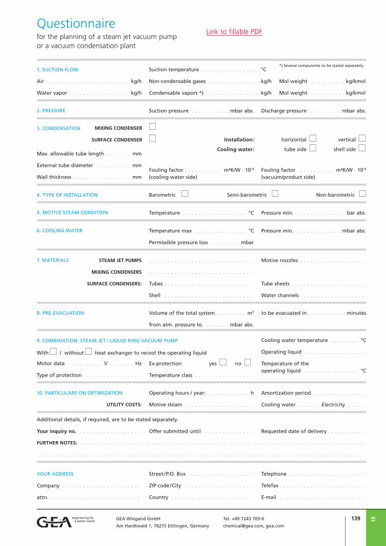
139GEA Wiegand GmbH Tel. +49 7243 705-0
Am Hardtwald 1, 76275 Ettlingen, Germany [email protected], gea.com
18
Questionnairefor the planning of a steam jet vacuum pump or a vacuum condensation plant
Street/P.O. Box . . . . . . . . . . . . . . . . . . .
ZIP code/City . . . . . . . . . . . . . . . . . . . .
Country . . . . . . . . . . . . . . . . . . . . . . . .
Company . . . . . . . . . . . . . . . . . . . . . . .
attn. . . . . . . . . . . . . . . . . . . . . . . . . . .
YOUR ADDRESS Telephone . . . . . . . . . . . . . . . . . . . . . .
Telefax . . . . . . . . . . . . . . . . . . . . . . . . .
E-mail . . . . . . . . . . . . . . . . . . . . . . . . .
Air . . . . . . . . . . . . . . . . . . . . . . . kg/h
Water vapor . . . . . . . . . . . . . . . . . kg/h
1. SUCTION FLOW Suction temperature . . . . . . . . . . . . . . . . . °C
Non-condensable gases . . . . . . . . . . . . . . . kg/h
Condensable vapors *) . . . . . . . . . . . . . . . . kg/h
Mol weight . . . . . . . . . . kg/kmol
Mol weight . . . . . . . . . . kg/kmol
Suction pressure . . . . . . . . . . . mbar abs.2. PRESSURE Discharge pressure . . . . . . . . . . mbar abs.
Barometric Semi-barometric Non-barometric 4. TYPE OF INSTALLATION
5. MOTIVE STEAM CONDITION Temperature . . . . . . . . . . . . . . . . . . °C Pressure min. . . . . . . . . . . . . . . bar abs.
6. COOLING WATER Temperature max . . . . . . . . . . . . . . . °C
Permissible pressure loss . . . . . . . . mbar
Pressure min. . . . . . . . . . . . . . mbar abs.
3. CONDENSATION MIXING CONDENSER
SURFACE CONDENSER Installation: horizontal vertical
Cooling water: tube side shell side
7. MATERIALS . . . . . . . . . . . . . . . . . . . . . . . . . . . . . .
. . . . . . . . . . . . . . . . . . . . . . . . . . . . . .
Tubes . . . . . . . . . . . . . . . . . . . . . . . . . .
Shell . . . . . . . . . . . . . . . . . . . . . . . . . .
Motive nozzles . . . . . . . . . . . . . . . . . . .
Tube sheets . . . . . . . . . . . . . . . . . . . . .
Water channels . . . . . . . . . . . . . . . . . .
STEAM JET PUMPS
MIXING CONDENSERS
SURFACE CONDENSERS:
9. COMBINATION: STEAM JET / LIQUID RING VACUUM PUMP
Motor data . . . . . . . . . . V . . . . . . . Hz
Type of protection . . . . . . . . . . . . . . . .
Ex-protection yes no
Temperature class . . . . . . . . . . . . . . . . .
Cooling water temperature . . . . . . . . °C
Operating liquid . . . . . . . . . . . . . . . . . .
Temperature of the operating liquid . . . . . . . . . . . . . . . . °C
Max. allowable tube length . . . . . . . mm
External tube diameter . . . . . . . . . . mm
Wall thickness . . . . . . . . . . . . . . . . . mmFouling factor . . . . . . . . . . . m²K/W · 10-4
(cooling water side)Fouling factor . . . . . . . . . . m²K/W · 10-4
(vacuum/product side)
With / without heat exchanger to recool the operating liquid
10. PARTICULARS ON OPTIMIZATION Operating hours / year: . . . . . . . . . . . . h
Motive steam . . . . . . . . . . . . . . . . . . . .
Amortization period . . . . . . . . . . . . . . .
Cooling water . . . . . . . Electricity . . . . .UTILITY COSTS:
FURTHER NOTES: . . . . . . . . . . . . . . . . . . . . . . . . . . . . . . . . . . . . . . . . . . . . . . . . . . . . . . . . . . . . . . . . . . . . . . . . . . . . . . . . . . .
. . . . . . . . . . . . . . . . . . . . . . . . . . . . . . . . . . . . . . . . . . . . . . . . . . . . . . . . . . . . . . . . . . . . . . . . . . . . . . . . . . . . . . . . . . . . . . .
Additional details, if required, are to be stated separately.
Your inquiry no. . . . . . . . . . . . . . . . . . . Offer submitted until . . . . . . . . . . . . . . Requested date of delivery . . . . . . . . . . .
8. PRE-EVACUATION Volume of the total system . . . . . . . . . m3
from atm. pressure to . . . . . . . mbar abs.
to be evacuated in . . . . . . . . . . . minutes
*) Several components to be stated separately.
Link to fillable PDF

18 140 GEA Wiegand GmbH Tel. +49 7243 705-0
Am Hardtwald 1, 76275 Ettlingen, Germany [email protected], gea.com


BTC
0011
-EN
041
8
© G
EA W
iega
nd G
mbH
. All
right
s re
serv
ed.
Su
bjec
t to
mod
ifica
tions
. Prin
ted
in G
erm
any.
GEA Deutschland
GEA Wiegand GmbH
Am Hardtwald 1
76275 Ettlingen
Tel +49 7243 705-0
Fax +49 7243 705-330
gea.com
GEA is a global technology company with multi-billion euro sales operations in more than 50 countries. Founded in
1881 the company is one of the largest providers of innovative equipment and process technology. GEA is listed in the
STOXX® Europe 600 Index. In addition, the company is included in selected MSCI Global Sustainability Indexes.
We live our values.Excellence • Passion • Integrity • Responsibility • GEA-versity

![Analyst Call - gea.com GEA... · 1/24/2018 · GEA Conference Call Presentation 6 preliminary numbers rounded [EUR m] Projected H2 2017 as per Q2 2017 (lower case) Sales Op. EBITDA2](https://img.pdfslide.us/doc/110x75/5f8949f6fc9bd74790530b24/analyst-call-geacom-gea-1242018-gea-conference-call-presentation-6.jpg)