Embed Size (px)
DESCRIPTION
Production for bilding Remote Terminal Systems and SCADA: ENIP-2, PMU, WAMS and other.
Citation preview

1


Dear colleagues and partners!
Thank you for your attention to the products and solutions of Engineering Center "Energoservis". We are pleased to present our new catalog. In 2015, we release upgraded devices with improved performance, enhanced functionality and renewed design.
Our flagship product is ENIP-2 which opens new possibilities for substation automation and power plants. In 2014, ENIP2 IEC61850 complience was confirmed by numerous tests. Today, ENIP-2 is the leader among multi-functional transducers in Russia. ENIP-2 provides high accuracy measurements, and integrates easily into automated systems infrastructure.
ENMV digital input/output device range welcomes a new modification that supports IEC 61850.
Remote Terminal Units ENCS-3m are ready to operate in the remote control systems at the facilities of any level.
We continue producing devices for Wide Area Measurement System (WAMS): phasor measurement unit (PMU) ENIP-2, phasor data concentrator ES PDC, analog input module ENMV-3 and diagnostic display panel ENMI-6.
We focus our attention on the quality of our products, improving the production system, and creating our new laborato-ry for testing and research. Our products are certified to comply with the standards of electrical safety and electromag-netic compatibility. Each product passes interoperability tests, climatic and mechanical tests. Each manufactured device undergoes a full cycle of acceptance tests.
The advantages of our products are based on scientific research and new developments, the continuous search for new ideas and focus on customer satisfaction. Success of our customers inspires us to new developments.
2 ENIP-2multifunctional power meters
16 ENMIdisplay panels
20 ENMVi/o modules
28 ENCS-2time sync module
30 ENCS-3Mremote terminal units
34 ENCMcommunication modules
38 ОPTIONSANDACCESSORIES

2
multifunctional power meters
ENIP-2
ENIP-2 is a series of multifunctional power meters for three-phase electrical networks. ENIP-2 is designed for metering and telecontrol in automated systems of elec-tric power substations. ENIP-2 also can serve as a basic bay control unit.
The success of ENIP-2 is the result of the following three factors: rich functionality, high quality, and reasonable price. These three factors combined together with supply terms provide great opportunities for electric power system engineers, designers and maintenance personnel.
Outlined features increase observability of electric power systems, providing Smart Grids with state of the art automated process control systems.
High quality of measurements is provided by the ap-plication of specific processing algorithms. Reliable and fast data transmission from remote facilities is imple-mented using redundant interfaces and contemporary communication protocols.
ENIP-2 is connected to three- or four-wire network directly or through current and voltage transformers. ENIP-2 may be installed in protection compartments of enclosed switchgear, in panels and cabinets. Due to wide operating temperature range, ENIP-2 can be applied in unattended and non-heated facilities.
ENMI display panels are designed to be a human inter-face of ENIP-2. ENMI is easily connected to ENIP-2 with RJ45 patch cord.
ENIP-2 supports a range of communication protocols:
Modbus RTU, Modbus TCP, IEC 60870-5-101, IEC 60870-5-104 and IEC 61850.
Equipped with four to eight digital inputs (depending on the chosen model) ENIP-2 is capable of processing the state of several switchgears and protection relays.
To control switchgears any model of ENIP-2 can be paired with an external ENMV module, or a model with three built-in digital outputs can be used.
ENIP-2 provides ease of both protocol configuration and firmware upgrade via USB-port, which can be used for measurement data transfer as well. No driver installation is needed.
Connected to USB, ENIP-2 operates without auxiliary power supply. ENIP-2 can be configured from a PC with included software or built-in web-console.
ENIP-2 is a large family of devices that can be divided into three branches:
• a series of power meters in plastic housing for DIN-Rail mounting
• a series of power meters in compact metal body
• a series of phasor measurement units in plastic hous-ing combined with a color LCD display for mounting on panels or cabinets.

3
The series of ENIP-2 in plastic case housing for DIN-rail mounting includes four models that differ in cost and capabilities.
The simplest meter comes with a single RS-485 interface to suit any low-cost solution.
The most complex model comes with 2 RS-485 interfaces, 2 Ethernet ports, up to 8 digital inputs and 3 digital outputs.
Additional communication interfaces may as well serve for pairing with external modules for extended digital I/O functionality and display.
The series of models in compact metal body is designed for use in 6–20 kV switchgear cells where only small devices can be installed.
Single ENIP-2 can be sufficiently used as a bay controller unit. Apart from measurements, it provides remote signaling with digital inputs and switchgear control with electromagnetic relay outputs.
This series has redundant data interfaces and power inputs to provide increased reliability.
This is a series of phasor measurement units (PMUs) that are used for building wide area monitoring systems (WAMS).
WAMS open new perspectives for: • monitoring power grid state
• detecting and preventing further grid instabilities
• verifying power grid model
• analysing system failures.
Time sync, which is critical for PMU devices, is provided by the global positioning systems. ENIP-2 uses a built-in GPS-receiver, or is synchronized by an external ENCS-2 module.
ENIP-2 Family
Flagship Line
Compact Design
Phasor Measurement Unit

4
Measurements
RMS and first harmonic values of: • voltages (phase, line-to-line and average)
• currents (phase and average)
• power (active, reactive and apparent: phase and total)
• And also:
• frequency
• power factor (phase and average)
• active and reactive energy in both forward and re-verse directions.
Power quality: • voltage sequences
• voltage unbalance and distortion
• current sequences
• current unbalance and distortion
• THD
ENIP-2 uses 50 ms sliding window measurement calculation method. The values are updated every 20 ms.
For monitoring purposes ENIP-2 has a set of configurable thresholds.
USB port
RS-485-1 (Modbus RTU, IEC 60870-5-101)
Power supply input
Current and voltage inputs
ENIP-2 measures the full set of three-phase electrical network parameters. Single RS-485 interface is used for data transfer.
This model is aimed for use at small substations and distribution points.
Flagship Line → minimal

5
This model is equipped with 3 RS-485 interfaces and 1 Ethernet 100Base-T.
ENIP-2 with an Ethernet 100Base-T port can be integrated into IEC 61850 digital substation infrastructure.
ENIP-2 acts as MMS server and is capable of publishing and subscribing to GOOSE messages. Combined with logic expressions evaluation, it allows ENIP-2 to be used for circuit breaker interlocking.
RS-485-3(Modbus RTU, IEC 60870-5-101)
Ethernet 100Base-T,(IEC 61850, IEC 60870-5-104,Modbus TCP, SNTP, SNMP, NETBIOS,pass-through mode to any RS-485, andweb-console for protocol configuration)
Dry contacts 24 V DC power supply
Digital inputs and outputs
RS-485-2 two RJ45 sockets are wired in parallel.ENMI panel is connected with a single patch cord to the right socket which also serves as power supply.The left socket is a regular RS-485 (Modbus RTU, IEC 60870-5-101). It may be used to connect other external modules, such as ENMV.
Flagship Line → extended
This model is equipped with 4 or 8 digital inputs, and 3 or no digital outputs. For digital inputs, both wet and dry contacts are supported. Dry contacts are powered by built-in 24 V DC supply. Digital outputs are based on solid state relays.
RS-485 interfaces operate independently.
RS-485-2 may be used to connect an ENMI display panel and up to 4 ENMV-1 I/O modules.
Flagship Line → basic

6
Flagship Line → maximum
2 x Ethernet 100Base-T,(IEC 61850, IEC 60870-5-104,Modbus TCP, SNTP, SNMP, NETBIOS,pass-through mode to any RS-485, andweb-console for protocol configuration)
This model comes with two Ethernet ports and a built-in switch that supports RSTP (Rapid Spanning Tree Protocol , IEEE 802.1D) and PRP (Parallel Redundancy Protocol, IEC 62439-3).
100Base-T or 100Base-FX (LC multi-mode) Ethernet implementations are available.
2 x Ethernet 100Base-FX,(IEC 61850, IEC 60870-5-104,Modbus TCP, SNTP, SNMP, NETBIOS,pass-through mode to any RS-485, andweb-console for protocol configuration)

7
Measurements rated current: 1 or 5 А, rated voltage: 57,7 (100) or 220 (380) V
Voltage (input range: 20–150 %) ±0,2 %
Current (input range: 1–200 %) ±0,2 %
Power (active/reactive/apparent) ±0,5 %
Frequency ±10 mHz
Power quality U0, U1, U2, K2U, KU, I0, I1, I2, K2I, KI, THD
Digital inputs/outputs
Inputs 0, 4 or 8 (dry or wet contact)
Outputs 0 or 3 (solid state relay, 300 V DC / 250 V AC, 100 mA)
Optional modules
display ENMI
digital inputs/outputs ENMV(up to 4 digital inputs and up to 12 electromagnetic relay outputs)
Communication
RS-485 1–3 ports — Modbus RTU, IEC 60870-5-101 (600–115200 bit/sec)
Ethernet 100Base-T Ethernet 100Base-FX (LC sockets, fiber multi-mode)
1 or 2 ports — IEC 61850, IEC 60870-5-104, Modbus TCP, SNTP, SNMP, NETBIOS, pass-through mode to any RS-485, web-console for protocol configuration2 port model comes with built-in switch that supports RTSP, PRP.
Real time clock
Maximum error 0,5 msec
Time synchronization Ethernet (IEC 60870-5-104 C_CS_NA_1, SNTP) or RS-485 (IEC 60870-5-101 C_CS_NA_1)
Event logging status of digital input and outputs, diagnostic messages; software update, configuration change, power supply events
Power supply
Input voltage 18–36 V DC or universal 120–370 V DC / 100–265 V AC (45–55 Hz)
Power consumption 4 VA (10 VA with ENMI powering from 24V= Port 2)
Operating conditions and design
Operating temperature from −40 to +70 °C
Design and mounting plastic housing 75х100х110 mm, DIN-rail mountingIP40
Specification

8
Ordering InformationPower supply voltage 220 – 100–265 V AC (45–55 Hz)or 120–370 V DC24 – 18–36 V DC
Interfaces and digital inputs/outputsA1E0-01 – 1 x RS-485A2E0-11 – 2 x RS-485, 4 digital inputs, 3 digital outputsA2E0-21 – 2 x RS-485, 8 digital inputsA3E4-21 – 3 x RS-485, 1 x Ethernet 100Base-T, 8 digital inputsA2E4x2-21 – 2 x RS-485, 2 x Ethernet 100Base-T, 8 digital inputsA2E4x2FX-21 – 2 x RS-485, 2 x Ethernet 100Base-FX,8 digital inputs (wet contact)
ENIP-2-4 X / X - X - X - X1
Conformance toLVS EN 61010-1:2011 (EN 61010-1:2010), EN 61000-4-3, EN 61000-4-4, EN 61000-4-5,EN 61000-4-6, EN 61000-4-8, EN 61000-4-11.
Conformanceto EU RoHS directive(№2002/95/EC).
Оptions and accessories
ES61850.enipIEC 61850-8-1 support for ENIP-2 (applies to А3Е4-21, А2Е4x2-21, А2Е4x2FX-21 only), MMS server (up to 4 clients), publish 8 GOOSE messages, subscribe to 10 GOOSE messages.
Rated voltage100 – 57,7 V (L-L 100 V)380 – 220 V (L-L 380 V)
Rated current1 – 1 А5 – 5 А

9
Compact Design → minimal
2 x RS-485, 2 x power supply inputs
Voltage inputs
3 built-in electromagnetic relay outputs
12 digital inputs (wet contact)
3 additional voltage inputs
USB port
Status LEDs (interfaces, I/O)
Compact Design → basic
ENIP-2 in metal housing combines compact design with extended functionality.
Measured parameters, metrological characteristics and processing speed are identical to those of standard ENIP-2 modification (see page 7).
Mounting brackets for installation in enclosed switchgears of different type are available.
Distinguishing features: • 3 additional voltage inputs for the detection of the
presence of voltage on voltage divider insulators in 6–20 kV networks
• 3 built-in electromagnetic relays
• Two power supply inputs
• Two independent RS-485 interfaces
Current inputs
This model is one phase, current only (only additional voltages are measured). Digital inputs and outputs are the same as of basic compact model. This model will suit any a low-cost solution.

10
Measurements See page 7
Input/output
Digital inputs 12 (dry or wet contact)
Digital outputs 3 outputs (cascade of electromagnetic relays and high power solid state relays); switching capacity; 250 V, 6A DC / AC
Analog inputs 3 additional voltage inputs (1–300 V AC)
Optional modules
see page 7
Communications
2 х RS-485 (600–115200 bit/sec) Modbus RTU, IEC 60870-5-101
Real time clock
Accuracy 0,5 msec
Time synchronization RS-485, IEC 60870-5-101 C_CS_NA_1 (103)
Event logging status of digital input and outputs, diagnostic messages; software update, configuration changing, power supply events
Power supply
Input voltage / Power consumption 18–36 V DC / 5 VA
Operating conditions and design
Operating temperatureDesign and mounting
from −40 to +70 °C130х100х58 mm metal housing, IP40DIN-rail mounting or special bracket (see Options and Accessories)
Specifications
Rated current1 — 1 А5 — 5 А
Rated voltage100 — 57,7 V (L-L 100 V)380 — 220 V (L-L 380 V)0 — no voltage inputs
Connection type 1 — one phase (minimal)4 — three phase (basic)
ENIP-2-X X / X-24-А2Е0-32Оptions and accessories
DIN-BRBracket for ENIP-2-..-32 (metal housing) for mounting on DIN-rail. Aluminum alloy
RM6-BRBracket for ENIP-2-...-32. Stainless steel 1,5 mm
Ordering Information

11
ENIP-2 family includes a series of devices with Phasor Measurement Unit (PMU) functionality.
PMUs are used in automated control systems of substations and power plants, being the key component of Wide Area Measurement Systems (WAMS). WAMS are used to monitor power grids, detect and prevent power grid instabilities.
Signal processing algorithms of ENIP-2 are implemented in accordance with IEEE C37.118.1. The accuracy of synchrophasor measurements is not influenced by electromagnetic transients free components and higher harmonics.
Time sync, which is critical for PMU devices, is provided by the global positioning systems. ENIP-2 uses a built-in GPS-receiver, or is synchronized by an external ENCS-2 module. Several devices can be synchronized by a single ENCS-2 or ENIP-2 with GPS-receiver.
ENIP-2 PMU can be installed on panels or in cabinets. Typically it is installed in special cabinets, along with other components of WAMS.
Uninterruptible power supply and redundant communication channels are critical for WAMS stability.
ENIP-2 PMU has 5 digital inputs and 3 interfaces: Ethernet 100Base-T, RS-485 (for IRIG-A synchronization), and RS-232 (service port).
The following features are optional: • built-in GPS-receiver
• TFT color touch screen display to view the measure-ment values as diagrams (synchrophasor or oscillo-scope), or in tables
ENIP-2 is one the most compact PMU devices ever. It is easy to install and connect in any environment. Current and voltage inputs are protected from unauthorized access by a cover that can be sealed.
Data link protocols IEEE C37.118.2 and IEC 60870-5-104 are supported. Datarate from 50 to 200 frames per second is supported.
Both IEEE C37.118.1 measurement classes P and M are supported, and are cofigurable by end user.
ENIP-2 with IEC 61850-9-2LE process bus input support can be used in digital substations.
4,3" TFT color touch screen display, 480х272
RS-485 (IRIG-A) combined with RS-232 (service port)
5 digital inputs
Current and voltage inputs
Ethernet 100Base-T
Power supply input
Built-in GPS-receiver
Phasor measurement unit → PMU

12
Measurements See page 7
Digital inputs/outputs
Inputs 5 (dry contact)
Communications
RS-485 time sync using IRIG-A (with ENCS-2 time sync module)or transmitting IRIG-A to another PMU if PMU have built-in GPS-receiver
RS-232 (19200 bit/sec) service port to update firmware
Ethernet 100Base-T IEC 60870-5-104 (up to 4 clients), IEEE C37.118.2-2011 (up to 4 clients)
Real time clock
Accuracy 1 µs if clock synced
If no time sync Within 10 minutes after the loss of time synchronization error in time is still 1 µs
Source of time sync ENCS-2 time sync modul, RS-485 (IRIG-A)
Options
Built-in GPS-receiver to receiving time and coordinates
Built-in display 4,3’’ TFT color touch screen , 480х272
Power supply
Voltage of power supply 18–36 V DC or universal 120–370 V DC / 100–265 V AC (45–55 Hz)
Power consumption 10 VA
Operating conditions and design
Operating temperatureDesign and mounting
from −40 to +70 °C or –10...+70°С if equiped with TFT display160х165х83 mm plastic housing,panel or cabinet mounting, IP40
Options03 – 1 x RS-485, 1 x Ethernet 100Base-T, 5 digital inputs, PMU functions13 – ... + TFT color touch screen 23 – ... + built-in GPS/GLONASS-receiver
ENIP-2 - 4X / X - X - A1E4 - XX
Ordering Information
Specifications
Power supply voltage 220 – 100–265 V AC (45–55 Hz) or 120–370 V DC24 – 18–36 V DC
Rated voltage100 – 57,7 V (L-L 100 V) - connection to potential transformer380 – 220 V (L-L 380 V) - direct connection to power line
Rated current1 – 1 А5 – 5 А

13
KVM with с 17’’ LCD monitor
UPS
ES PDC — phasor data concentrator
Terminal blocks of current and voltage
PMU ENIP-2
ENMI-6 — display panel for diagnostic messages
ENCS-2 - time sync module
PMU ENIP-2 is ideal for creating Wide Area Measurement Systems. We provide all the necessary software and hardware to create WAMS on substations and power plants.
The WAMS equipment is located usually in one or more rack cabinet. We also produce special versions cabinets on request, which are made according to customer requirements.
Phasor measurement unit → WAMS
WAMS lets solved a number of problems: • providing measurement synchrophasors in real time;
• global monitoring of transmission system conditions over large areas;
• detecting and preventing further grid instabilities.
• verifying model of power grid;
• emergency record archives and emergency events, visualization of dynamic characteristics of the system, analysis of power grid failures.
WAMS based on equipment produced Engineering centre "Energoservice" include: • ENIP-2 (PMU);
• ES PDC — phasor data concentrator;
• ENCS-2 — time sync module (IRIG-A time code se-quence);
• ENMV-3 — analog input modules for controlling the parameters of generator excitation (for power plants);
• ENMI-6 — diagnostic subsystem;
• UPS — uninterruptible power supply subsystem;
• communications equipment (switches, routers).

14
Measurements (PMU)
Number of PMU ENIP-2 1…6 in one cabinet:maximum 40.
Controlling the parameters of generator excitation
Analog input modules ENMV-3 ENMV-3 are mounted in WAMS cabinets or on panels near the primary sensors
Digital inputs
5 inputs "dry contacts" to monitoring state of the measuring circuits (cover of terminal blocks), state of cabinet door and other digital signals
Phasor data concentrator
Type ES-PDC, up to 40 inputs (PMU), up to 4 Outputs, 240/360Gb
Number of PDC 1 or 2 (redundant)
Time sync subsystem
Time sync module ENCS-2 GPS-receiver with IRIG-A time code sequence
Diagnostic subsystem
Type Display panel ENMI-6 (4,3" TFT color touch screen, 480x272) withalarm digital output.
Monitored equipments PMU, PDC, time sync subsystem, UPS, network
Power supply
Type of power supply system up to 2 power supply inputs, UPS with battery support (3000 VA)
Voltage of power supply 160...286 V AC
Power consumption 500 VA
Operating conditions and design
Operating temperature from 0 to +55 °C
Housing Enclosure cabinet, sheet steel, glass door, 2200х800х800 mm
Specifications

15
Type of power supply system 1 – 1 input + UPS2 – 2 inputs + UPS0 – 1 input, w/o UPS
Analog inputnumber of ENMV-3 PDC type
C – 1x ES PDCCR – 2 x ES PDC0 – w/o PDC
PMUnumber of PMU ENIP-2in one enclosure
Additional requirmentsD – diagnostic subsystem (ENMI-6)FXS... – number of fiber optic ports (single-mode)FXM... – number of fiber optic ports (multi-mode)T100... – number of Ethernet 100Base-T portsT1000... – number of Ethernet 1000Base-T ports
WAMS - X X - X - X .. X - X
Ordering Information
Оptions and accessories
GPS-B3.15, GPS-B3.45GPS outdoor antenna (feeder long 15 m or 45 m, SMA connector)
GPS-BR-miniCompact bracket for mounting GPS antenna. Stainless steel 1,5 mm
GPS-BR-300, GPS-BR-500, GPS-BR-1000Steel bracket for mounting GPS antenna, 300/500/1000 mm

16
display panels
ENMI
Function
ENMI displays values of main measured and calculated parameters received from ENIP-2. Also EMNI may used for displaying service data from other devices and systems.
Display panel ENMI is designed for ENIP-2 to display of measured values. Usage of ENMI as switchboard instru-ments provides identity of measurements, transmitted to SCADA and readings on the devices at the facilities.
ENMI produced in different version: LEDs, TFT color touch screen, monochrome LCD. Depending from version they have special functionality.
For example, ENMI-3 based on LEDs have a long life and extended temperature range. Its main purpose is to display measured values received from ENIP-2.
It have big and bright LED digital display segments and allow well-read values. ENMI-3 displays values of main parameters of three-phase electrical network .
ENMI-4 are based on 4", FSTN LCD displays and have extended functionality, allowing for display of different values in specific form:
• digital indicator;
• bar graph;
• diagram of switchgear device with displaying of basic nets parameters).
The color touch screen ENMI-5 has a lot of informa-tion display forms and may looks even like pointer-type instrument.
Data from one ENIP-2 may be displayed on several ENMI or one ENMI can display data from several ENIP-2.
ENMI-6 has a Ethernet port, which allows the use it for displaying data in automated systems of "digital substa-tions". Another software version lets use ENMI-6 for diagnose WAMS equipment.
ENMI may be mounted on panels in hole 110*110 mm. Also ENMI may be combined constructively with ENIP-2 and looks like one device.
Data display • connects to ENIP-2 and displays values of measured
and calculated parameters, digital inputs status;
• independent display unit for viewing equipment sta-tus, supervision of software and hardware units.
Generation of alarms
ENMI is capable of supervising the limits. When one of the parameters violates the preset limits, there is a specific indication and display visualizes this parameter on the screen.
Control
ENMI-5 provides sending control command to ENIP-2.
17
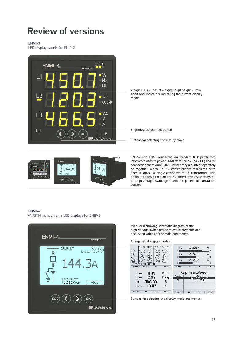
ENMI-3 LED display panels for ENIP-2
Review of versions
ENIP-2 and ENMI connected via standard UTP patch cord. Patch cord used to power ENMI from ENIP-2 (24 V DC) and for connecting them via RS-485. Devices may mounted separately or together. When ENIP-2 constructively associated with ENMI it looks like single device. We call it "transformer". This flexibility allow to mount ENIP-2 differently: inside relay cell of high-voltage switchgear and on panels in substation control.
ENMI-4 4", FSTN monochrome LCD displays for ENIP-2
Buttons for selecting the display mode
Brightness adjustment button
7-digit LED (3 lines of 4 digits), digit height 20mmAdditional indicators, indicating the current display mode
Main form showing schematic diagram of the high-voltage switchgear with active elements and displaying values of the main parameters.
Buttons for selecting the display mode and menus
A large set of display modes:

18
ENMI-54.3" TFT LCD touch screen displays for ENIP-2
ENMI-64.3" TFT LCD touch screen multipurpose displays
ENMI-6, depending on the firmware can be used in the following applications: • Panel for displaying diagnostic information about
WAMS equipment, it displays equipment status and has alarm digital output for outer systems;
• Display panel for substation control systems using IEC 61850: displaying values received over MMS or GOOSE.
ENMI-5 serve to display measured values of ENIP-2 on several screens: • as pointer-type instrument;
• set of digital indicators;
• set of graphs;
• voltage and current phasors diagram.
A large set of display modes:

19
Type of display3 – LED for ENIP-24 – LCD FSTN monochrome for ENIP-25 – LCD TFT touch screen for ENIP-26 – LCD TFT touch screen multipurpose display
ENMI - X - 24 - 2
ENMI-3 ENMI-4 ENMI-5 ENMI-6
Type of display
LED 7-digit LED (3 lines of 4 digits), digit
height 20x11 mm
4", FSTN monochrome 240х128 pix
4.3", TFTtouch screen480х272 pix
Communications
Interface
RS-485 (Modbus RTU)
RS-485 (Modbus RTU) or Ethernet (IEC 61850, SNTP,
SNMP)
Power supply
Input voltage 18–36 V DC
Power consumption 5 VA 3 VA
Operating conditions and design
Operating temperature from −40 to +55 °C from −10 to +55 °C from 0 to +55 °C
Design and mounting 120х120х49 mm plastic housing, panel or cabinet mounting,IP30 (111х111 mm square hole), ENMI constructively combines with ENIP-2.
Specifications
Ordering Information
Conformance toLVS EN 61010-1:2011 (EN 61010-1:2010), EN 61000-4-3, EN 61000-4-4, EN 61000-4-5,EN 61000-4-6, EN 61000-4-8, EN 61000-4-11.
Conformanceto EU RoHS directive(№2002/95/EC).

20
i/o modules
ENMV
ENMV is the series of i/o modules intended for use in the remote terminal units and automated systems at substations and power plants.
ENMV, ENIP-2 and ENCS-3m together allow you to create distributed systems of remote control of various power facilities.
Main purpose of ENMV is input and output digital and analog signals and data transfer via galvanically iso-lated interfaces RS-485 and Ethernet.
ENMV may transfer data directly or through ENIP-2, ENCS-3m or other automation equipment.
The series includes:
• ENMV-1 — i/o modules with 4, 12 or 24 digital inputs, 6 or 22 digital outputs based on solid state relay or 3 relay outputs;
• ENMV-2 — i/o modules with 4 digital inputs, 3 relay outputs and 4 analog inputs (3 voltages and 1 cur-rent);
• ENMV-3 — analog input modules with 2 inputs. ENMV-3 is designed for WAMS to control the param-eters of generator excitation (for power plants);
• ENMV-1W — input modules for interfacing with tem-perature sensors on the bus 1-Wire.
•
ENMV-1 and ENMV-2 equipped with relay outputs allow control switchgear.
ENMV-2 — is designed for use in electric distribution networks 6-20 kV. ENMV-2 provides remote control, digital inputs, analog inputs and allows to control the voltage on the three phases (from the capacitive divider base insulators cable lines).
ENMV real time clock is synchronized by ENCS-2 or by other time sync sources. ENMV has events log of i/o statuses. Each record of event log is marked with time stamp with 1 ms resolution.
All data from ENMV are transmitting to the upper level via RS-485 or Ethernet.

21
Review of versionDigital inputs and control
2 х RS-485 (Modbus RTU,IEC 60870-5-101)
Ethernet 100Base-T (IEC 60870-5-104, Modbus TCP, IEC 61850)LEDs input statuses
Terminal blocks of inputs
Power supply inputs
ENMV-1-24/0
Digital inputs of 24 "wet contacts" or "dry contacts".
"Dry contacts" are powered by internal power supply of ENMV (24 V DC).
ENMV-1-0/22
Digital outputs for control switchgear or other equipment.
ENMV-1-0/22 is designed to output the control commands via the 20 digital outputs (DO, low-voltage solid-state relays) and 2-speed output (TRIP, solid state relays for power applications).
2 х RS-485 (Modbus RTU,IEC 60870-5-101)
Ethernet 100Base-T (IEC 60870-5-104, Modbus TCP, IEC 61850)
LEDs output statuses
Terminal blocks of outputs
Power supply inputs
USB port
USB port

22
ENMV-1-0/3R
Digital outputs for control switchgear or other equipment. ENMV-1-0/3R independently or under the control of ENIP-2 provides remote control command execution via the built-in electromagnetic relays.
ENMV-1-4/3R
Digital inputs and outputs for control switchgear or other equipment.
ENMV-1-4/3R is same ENMV-1-0/3R but added with 4 digital inputs for "wet contact" or "dry contact" signals ("Dry contacts" are powered by internal power supply of 24 V DC).
4 digital inputs
LEDs statuses: relay outputs, power, interface
RS-485 (1 port on double RJ-45)(Modbus RTU, IEC 60870-101)
3 electromagnetic relay outputs
Digital inputs and control
Power supply inputs

23
3 relay outputs
4 digital inputs
RS-485 (Modbus RTU)
Current and voltage inputs
Power supply inputs
LEDs statuses: relay outputs, voltage inputs
ENMV-2-4/3R is the optional module for ENIP-2 and used for monitoring and control in 6-20 kV grids. ENMV-2-4/3R is connected to the ENIP-2 via RS-485-2 port. ENIP-2 transfers the parameters measured and controlled ENMV-2, together with the rest of the volume of data being processed.
Digital input
ENMV-2-4/3R complements ENIP-2 with 4 digital inputs for "wet contact" or "dry contact" signals ("dry contacts" are powered by internal power supply of 24 V DC).
Control
ENIP-2 can control the switchgear via 3 built-in electromagnetic relays of ENMV-2-4/3R.
Monitoring
ENMV-2-4/3R has current and voltage inputs to control zero sequence current (3I0) and voltage from the capacitive dividers connected to the 6-20 kV.
i/o module for distribution 6-20 kV grids

24
Temperature monitoring
USB port
1-wire terminal blocks
2 digital outputs (SSR)
TS-1w — additional temperature sensor TS-SRS — shield for temperature sensor
By default ENMV-1W is used for temperature monitoring and support up to 30 sensors. The kit ENMV-1W includes two temperature sensors. Additional temperature sensors, as well as a protective screen against rain, wind and solar radiation ordered separately and are presented below.
LEDs statuses: relay outputs, power, interface
RS-485 (1 port on double RJ-45)(Modbus RTU, IEC 60870-101)
Power supply inputs
ENMV-1W designed to interfacing a remote control units of substations and non-electrical sensors such as temperature sensors, humidity sensors, security system sensors and so on. The exchange between ENMV-1W and sensors carried on the bus 1-Wire.

25
USB port
Power supply inputs
AnaloginputsRS-485
(IRIG-A)
2 х Ethernet100Base-T
Analog inputs for WAMS
ENMV-3 has two analog inputs. ENMV-3 can be used for remote control systems and other automated systems when necessary control the parameters of the DC network.
Main purpose of ENMV-3 is control of parameters of generator excitation systems at power plants in WAMS applications. ENMV-3 converts the DC voltages (excitation voltage from the shunt and voltage set in the excitation circuit) and transmits the values to ES PDC.
Input range signal for each input is specified when ordering. Thus EMNV-3 can be used for other applications.

26
ENMV-1-24/0 ENMV-1-0/22 ENMV-2-4/3RENMV-1-0/3R
(ENMV-1-4/3R)
ENMV-1W ENMV-3
Digital signals
Inputs 24 WC — 4 WC 0 (4 WС) — —
Outputs — 20 SSR, 2 TRIP 3 EMR (~10 А) 3 EMR (~7 A) 2 SSR —
Analog signals
Inputs
— —
0,010...2 А AC; 0,050...10 А AC;
3…300 V AC. —
temperature -55 °C ...+125° C(2 sensors in kit, up to 30
sensors)
±1000 V DC;±10 V DC;
±200 mV DC;±75 mV DC;±20 mA DC;±5 mA DC.
Communications
RS-485 (600...115200 bit/sec)
2 х RS-485:Modbus RTU, IEC 60870-5-101
1 х RS-485:Modbus RTU
1 х RS-485:Modbus RTU, IEC 60870-5-101
IRIG-A
Ethernet1 х 100Base-T:
IEC 60870-5-104, Modbus TCP, IEC 61850
— — —2 х 100Base-T:IEEE C37.118.2-
2010
Event logging
i/o statuses — —
Diagnostic — —
Power supply
Voltage of power supply 18–36 V DC or universal 120–370 V DC / 100–265 V AC (45–55 Hz)
Operating conditions and design
Operating temperature–40... +70°С
Housing Plastic, IP40 75х100х110 mm, Plastic, IP40
75х70х110 mm
Metal, IP40109x188x35
mm
Mounting 35 mm DIN-rail mounting
Specifications
Designation: WC — "wet contact", DC — "dry contact", SSR — solid state relay (digital outputs — low-voltage electronic solid state switches), TRIP — digital outputs on power electronic solid state switches), EMR — electro-mechanical relay (outputs on electromechanical relays).

27
Ordering Information
ENMV - X - X - X - Xi/o set
ENMV-1: 24/0 – 24 digital inputs 0/22 – 22 digital outputs 12/6 – 12 digital inputs / 6 digital outputs 0/3R – 3 relay outputs 4/3R – 4 digital inputs / 3 relay outputs
ENMV-1W: 0/2 – 1-wire bus, 2 digital outputs
ENMV-2: 4/3R – 4 digital inputs / 3 relay outputs, 3 voltage inputs, 1 current input
ENMV-3: X/... – DC voltage input (AI-1):
A – ±1000 V B – ±10 V 0 – AI-1 not used
.../X – DC voltage or current input (AI-2):B – ±10 V C – ±200 mV D – ±75 mV E – ±20 mA F – ±5 mA 0 – AI-2 not used
Power supply voltage 220 – 100–265 V AC (45–55 Hz)or 120–370 V DC24 – 18–36 V DC
Interfaces sets
ENMV-1-0/3R, ENMV-1-4/3R: А1 – 1 х RS-485
ENMV-1-12/6: А2Е0 – 2 х RS-485 А3Е4 – 3 х RS-485, 1 х Ethernet 100Base-T
ENMV-1-24/0, ENMV-1-0/22: А2Е0 – 2 х RS-485 А2Е4 – 2 х RS-485, 1 х Ethernet 100Base-T
ENMV-2-4/3R: А1 – 1 х RS-485
ENMV-1W: А1 – 1 х RS-485
ENMV-3: А1Е4х2 – 1 х RS-485, 2 х Ethernet 100Base-T
i/o module types1 – digital input and output1W – interfacing with 1-Wire temperature sensors2 – i/o module for 6-20 kV grids3 – analog input
Оptions and accessories
ES61850.enmvIEC 61850-8-1 support for ENMV-1 I/O module
TS-1wTemperature sensor for ENMV-1W
TS-SRSshield for temperature sensor TS-1w

28
An important part of any automated control system is a time sync system. Time synchronisation is needed for any devices, servers and user workstations.
The most significant is the exact timing in remote con-trol systems: any event or value must have a time stamp.
Precision time synchronizing is main factor in WAMS applications. To get better accuracy of time sync may use global navigation systems (GPS, GLONASS). We produce ENCS-2 — device for time sync special for using in remote control systems. In 2014 we have released upgraded hardware platform to improve usability and of ENCS-2.
ENCS-2 receives GPS signals to synchronize remote terminal units, transducers, servers using standard proto-cols (NMEA 0183, SNTP).
ENCS-2 may be set up to send commands protocol IEC 60870-5-101 C_CS_NA_1 (103) to synchronize several RTU or transducers. ENCS-2 has a bright OLED dis-play, control buttons on the front panel and interfaces that provide a variety of options for sending time sync signals. To use ENCS-2 is needed install it on DIN-rail, connect GPS antenna, switch on power and configure settings of module.
To get best receiving of satellite signals, recommend to install GPS antenna outside on the south side of the building.
time sync module
ENCS-2
Function • time synchronization of the internal clock of ENIP-2;
• generate a PPS signal for time correction..
• receiving of the signals of the navigation satellite systems, the sync time of the internal clock;
• Time synchronization in remote control units accord-ing to IEC 60870-5-101;
• Time synchronization on servers, workstations, auto-mated systems by using protocols NMEA 0183, SNTP;

29
Accuracy
± 500 nsec — Relative timing error of the front of the output pulse of 1 Hz relative to UTC
± 500 nsec — absolute error of synchronization of the front label synchronization IRIG-A relative to UTC
11 nsec — the minimum quantum of time adjustment
± 0,4 sec/day — absolute timing errors in the absence of satellites
Accuracy time synchronization computer is up to 0.5 sec and deteriorating due to delay execution OS API
Reliability
MTLB / Срок службы more than 35000 hours / more than 15 years
Operating conditions and design
Interfaces RS-232-1, RS-485-1: NMEA 0183, IEC 60870-5-101;RS-232-2: NMEA 0183; RS-485-2: IRIG-A; Ethernet 100Base-T: SNTP.
Frequency of synchronization According to IEC 60870-5-101 C_CS_NA_1 (103) from 1 minute to 99 days in increments of 1 min, IRIG-A — 100 msec, SNTP — by client request
Voltage of power supply 18–36 V DC or universal 120–370 V DC / 100–265 V AC (45–55 Hz), 5 VA
Operating temperature from −40 to +70 °C
Housing/mounting plastic, 83х100х110 mm, IP40 / 35 mm DIN-rail mounting
Specifications
GPS antenna (SMA connector)PPS output (SMA connector)
Control buttons
Power supply input
Ordering Information
ENCS - 2 - X . 1 . 1 Power supply voltage 1 — 100–265 V AC (45–55 Hz)or 120–370 V DC2 — 18–36 V DC
GPS-B3.15, GPS-B3.45 GPS outdoor antenna (feeder length 15 m or 45 m, SMA connector)
GPS-BR-mini Compact bracket for mounting GPS antenna. Stainless steel 1,5 mm
GPS-BR-300, GPS-BR-500, GPS-BR-1000 Steel bracket for mounting GPS antenna, 300/500/1000 mm
Interfaces
Оptions and accessories
OLED display

30
remote terminal units
ENCS-3m
ENCS-3m - is a reliable software and hardware platform for building remote control systems for substation and power plants. This is proven by a decade of experience operating of previous generation model ENCS-3.
Remote terminal unit (RTU) ENCS-3m is designed to cre-ate geographically distributed systems:
• at the field level installed devices (ENIP-2, ENB se-ries) which support measurement parameters values, monitoring digital signals and control by digital outputs to switchgears and mechanism;
• all this devices are connected to RTU ENCS-3m via RS-485 lines or local networks;
• RTU ENCS-3m collect, consolidate and distribute necessary data to a higher level of control systems. To control data traffic from field level devices ENCS-3m uses absolute and relative apertures. Timestamps of data are assigned by field devices.
ENCS-3m build on 32bit ARM microcontroller and pro-viding continuous operation for remote control systems. To increase reliability system ENCS-3m support 2 redun-dant modes: warm standby and hot standby.
ENCS-3m use hard real-time algorithm, and thus pro-vides high performance and reliability.
ENCS-3m polls devices according IEC 60870-5-101. ENCS-3m support up to 10 ports for device polling.
ENCS-3m allows setup up to 16 channels to transmit data to upper level using 2 LAN and RS-232/RS485 ports. 2 RTUs ENCS-3m connect through CAN-bus to support warm standby in pair.
RS-485 interface, RS-232, Ethernet can be distributed by the user between data collection from field devices and transmission of information to the top level.
To communicate with the field devices are preferred protocol IEC 60870-5-101, which provides for the regu-lation of traffic between the RTU and devices, and allows you to send a data with timestamp directly from the sources of their formation.
If you need compact and reliable RTU? Use ENCS-3m.

31
Review of version
LEDs statuses
GPS antenna (SMA connector)GSM antenna (SMA connector)
SIM-card slot, USB (service port)
Interfaces
Power supply input
GT option, rear view
Front view
Base configuration
ENCS-3m in base configuration have 6 x RS-485, 4 x RS-232, 2 x Ethernet, 1 x CAN. RTU is mounted on DIN-rail. The front panel has LEDs statuses: ports, power supply, mode status.
GT option
Sometimes there is not accessible channels except GSM — then may use GT option.
GT option has built-in GSM (GPRS) module and built-in GPS-receiver. RTU synchronizes his own clock and clocks of polled devices by using built-in GPS-receiver.

32
Data amount
8192 measurement values, 4096 digital signals
Polled devices
Maximum amount 240
Supporting type devices ENIP-2, ENMV series,Modbus RTU devices, IEC 60870-5-101any device or RTU with supporting IEC 60870-5-101
Communications
6 х RS-485 (300–115200 bit/sec)
Assigned by the user to poll devices or transmit data to the upper level4 х RS-232 (300–115200 bit/sec)
2 х Ethernet 100Base-T
CAN to support "warm standby"
GSM (GPRS) supported when option GT is available
USB service port for GT option
Amount of channels data transmitting to the upper level
Up to 16 channels Asynchronous serial: RS-485/232 (up to 4 channels)TCP / IP - up to 12 channels through one port or two Ethernet ports.GPRS - up to 4 channels
Amount port to poll devices
Up to 10 ports Asynchronous serial: RS-485/232 (up to 10 ports)UDP — through one or two Ethernet port.
Time sync
Time synchronization of RTU and polled devices — from GPS-receiver (GT option),— from upper level or by ENCS-2 according IEC 60870-5-101 C_CS_NA_1 (103)
Operating conditions and design
Voltage of power supply 18–36 V DC or universal 120–370 V DC / 100–265 V AC (45–55 Hz)
Power consumption 5 VA
Operating temperature from −40 to +70 °C
Housing/mounting plastic, 83х100х110 mm, IP40 / 35 mm DIN-rail mountingoptional - installation in the wall cabinet with accessories, IP66
Specifications

33
Ordering Information
ENCS-3m . X . 0 - X . X Power supply voltage 1 – 100–265 V AC (45–55 Hz)or 120–370 V DC2 – 18–36 V DC
Version: 648 – 6xRS-485, 4xRS-232, 2xEthernet 100Base-T 648GT – ... + GT option (GPS/GLONASS-receiver, GSM-module)
Mounting type1 – 35 mm DIN-rail mounting, IP40;2 – IP66, installation in the wall cabinet with accessories.
GSM-3G.3outdoor GSM antenna on magnetic base (feeder length 3 m)
GPS-B3.15, GPS-B3.45GPS outdoor antenna (feeder length 15 m or 45 m, SMA connector)
GPS-BR-miniCompact bracket for mounting GPS antenna. Stainless steel 1,5 mm
GPS-BR-300, GPS-BR-500, GPS-BR-1000Steel bracket for mounting GPS antenna, 300/500/1000 mm
Оptions and accessories

34
communication modules
ENCM
• Creating remote control system with data transfer according IEC 60870-5-104 via GPRS.
• Supporting remote configuring
ENCM-3 modules are designed to help control distrib-uted objects energy, transport and industry.
ENCM-3 provides transmission of technological infor-mation (digital signals and measurements) over the GSM (GPRS) from various devices installed in controlled facilities. It could be multifunctional transducers, relay protection terminal units, meters, I/O modules, etc.
ENCM-3 helps to build a remote control system for geo-graphically distributed objects.
Communication modules ENCM phelps to collect data from various devices on the network GSM. ENCM series provides an implementation of communication chan-nels for specific purposes: ENCM-1 — to collect data in energy accounting system, ENCM-3 — for remote control systems.
The main feature of ENCM-1 is to provide a link from remote object to the Automatic Meter Reading (AMR) systems with minimal maintenance costs.
ENCM-1 uses the GSM network and packet data mode GPRS. Also is available CSD mode. In most applications ENCM provides a constant TCP/IP connection between the center and object. ENCM support both connec-tion type — server and client. The connection mode is depending what type of IP addresing in GPRS is used - dynamic or static IP. Also ENKC-1 can synchronize time of meters, using the built-in GPS-receiver.
Function • Provide transparent channels via GSM (CSD, GPRS).
• Synchronize devices clock

35
Review of version
4 digital inputs
1 or 2 analog inputs
RS-485-2
Power supply input
RS-485-1
GPS antenna GSM antenna (SMA connector)
Ethernet 100Base-T
SIM-card slot
For remote control system
For AMR systems
Front view
Rear view
Top view
Front view Rear view
ENCM-3-X-А2Т-402
ENCM-1-X-АЕТ
GPS antenna GSM antenna (SMA connector)
Ethernet 100Base-T
SIM-card slot
Power supply input
RS-485-1

36
SpecificationsENCM-1 ENCM-3
Type of channels
WirelessWired
GSM: GPRS, CSDEthernet 100Base-T
Interfaces to devices
RS-485 (300–115200 bit/sec) 1 2
Amount of devices to connect/poll 254 32 (if device support Modbus RTU)64 (if device support IEC 60870-5-101)
Optional features
Digital and analog inputs
—
4 digital inputs («dry contact»);
2 analog inputs 0…20 mA DCor 1 analog input –20…20 mA DC
Built-in GPS/GLONASS-receiver Synchronize clock of meters Synchronize polled devices clock
Power supply
Voltage of power supply 18–36 V DC or universal 120–370 V DC / 100–265 V AC (45–55 Hz)
Power consumption 10 VA
Operating conditions and design
Operating temperature from −40 to +70 °C
Housingmounting
plastic, 150х90х45 mm, IP4035 mm DIN-rail mounting
plastic, 150х90х45 (150х90х60) mm, IP4035 mm DIN-rail mounting

37
Ordering Information
ENCM- X - X - X Interfaces and optional featuresENCM-1:A – 1 х RS-485 AET – 1 х RS-485, Ethernet 100Base-T,built-in GPS/GLONASS-receiver
ENCM-3:A – 1 х RS-485AT – 1 х RS-485, built-in GPS/GLONASS-receiverA2T-401 – 2 х RS-485, Ethernet 100Base-T, built-in GPS/GLONASS-receiver, 4 digital inputs, 1 analog inputA2T-402 – 2 х RS-485, Ethernet 100Base-T, built-in GPS/GLONASS-receiver, 4 digital inputs, 2 analog inputs
ENCM series: 1 – for AMR systems3 – for remote control system
Power supply voltage 1 – 100–265 V ACor 120–370 V DC2 – 18–36 V DC
GSM-3G.3outdoor GSM antenna on magnetic base (feeder length 3 m)
GPS-B3.15, GPS-B3.45GPS outdoor antenna (feeder length 15 m or 45 m, SMA connector)
GPS-BR-miniCompact bracket for mounting GPS antenna. Stainless steel 1,5 mm
GPS-BR-300, GPS-BR-500, GPS-BR-1000Steel bracket for mounting GPS antenna, 300/500/1000 mm
Оptions and accessories

38
Оptions and Accessories
To simplified device installation and getting additional opportunities, we offer a number of options and acces-sories: supporting additional protocols, GSM and GPS antennas, brackets and fasteners.

39
Activate additional protocols
ES61850.enip
IEC 61850-8-1 support for ENIP-2: MMS-server, publicate/subscribe GOOSE.(for models А3Е4-21, А2Е4x2-21, А2Е4x2FX-21)
ES61850.enmv
IEC 61850-8-1 support for ENMV: MMS-server, publicate/subscribe GOOSE.(for models А2Е4)
ENIP-2 accessories
DIN-BR
Bracket for ENIP-2-..-32 for mounting on DIN-rail. Aluminum alloy
RM6-BR
Bracket for ENIP-2-...-32. Stainless steel 1,5 mm
GPS-B3.15
GPS outdoor antenna, feeder length 15 m, SMA connector
GPS-B3.45
GPS outdoor antenna, feeder length 15 m, SMA connector
GSM-3G.3
outdoor GSM antenna on magnetic base, feeder length 3 m, SMA connector
Antennas and brackets
TS-1w
additional temperature sensor
TS-SRS
shield for temperature sensor — to protect temperature sensor from solar radiation, wind and sediments
ENMV-1w accessories
GPS-BR-MINI
Compact bracket for mounting GPS antenna. Stainless steel 1,5 mm
GPS-BR-300
Steel bracket for mounting GPS antenna, 300 mm
GPS-BR-500
Steel bracket for mounting GPS antenna, 500 mm
GPS-BR-1000
Steel bracket for mounting GPS antenna, 1000 mm

40
The company's products Engineering Center "Energoservice ", Ltd. has established itself as a reliable device, trouble-free operation which is confirmed by many years of operating experience in industrial enterprises and power facilities.
We control quality of used technologies, platforms and components at all stages from development to production. It make possible to provide high level quality of all our products. Warranty for all products is 3 years.
Our customers can always get quality technical support on issues related to the use of our products.
We offer free technical seminars for introduce with our products and solutions.
We participate in exhibitions, provide consulting in the design and operation of our equipment.
Use www.enip2.com to get more information about products and solutions. Please contact us if you need more information or you want to request an offer.
WARRANTY AND SUPPORT
Engineering Center "Energoservice" [email protected] www.enip2.com

All images are presented only as an example. Actual characteristics, such as color and screen forms may differ from what is shown. Specifications and design are subject to change without notice, so ask for confirmation of the information contained in this publication.

42